JP2017206366A - Winding device of rubber tape, winding method and manufacturing apparatus of rubber tape composite - Google Patents
Winding device of rubber tape, winding method and manufacturing apparatus of rubber tape composite Download PDFInfo
- Publication number
- JP2017206366A JP2017206366A JP2016100482A JP2016100482A JP2017206366A JP 2017206366 A JP2017206366 A JP 2017206366A JP 2016100482 A JP2016100482 A JP 2016100482A JP 2016100482 A JP2016100482 A JP 2016100482A JP 2017206366 A JP2017206366 A JP 2017206366A
- Authority
- JP
- Japan
- Prior art keywords
- rubber tape
- reel
- winding
- rubber
- winding device
- Prior art date
- Legal status (The legal status is an assumption and is not a legal conclusion. Google has not performed a legal analysis and makes no representation as to the accuracy of the status listed.)
- Pending
Links
Images

Abstract
Description
本発明は、未加硫のゴムテープをリールに巻き取る技術に関する。 The present invention relates to a technique for winding an unvulcanized rubber tape around a reel.
従来、タイヤの構成部材として、種々のゴムテープが使用されている((例えば、特許文献1参照))。タイヤの製造工程では、ゴムテープは、通常、リールに巻き取られた状態で保管されている。 Conventionally, various rubber tapes have been used as constituent members of tires (see, for example, Patent Document 1). In the tire manufacturing process, the rubber tape is usually stored in a state of being wound on a reel.
近年では、タイヤの製造精度を高めるため、より厚さの小さいゴムテープが用いられる傾向にある。 In recent years, rubber tape having a smaller thickness tends to be used in order to increase the manufacturing accuracy of the tire.
しかしながら、上述した薄手のゴムテープは、曲げ剛性が小さいため、その取り扱いに注意を要する。例えば、ゴムテープをリールに巻き取る工程では、ゴムテープの先端部がリールから離間する方向にカールすることがある。この場合、カールしたゴムテープの先端部を矯正しつつ、リールに巻き付けなければならないため、作業効率の低下を招来している。 However, since the thin rubber tape described above has a low bending rigidity, it needs to be handled with care. For example, in the step of winding the rubber tape around the reel, the tip of the rubber tape may curl in a direction away from the reel. In this case, it is necessary to wind the curled rubber tape around the reel while correcting the tip portion of the curled rubber tape, resulting in a reduction in work efficiency.
ゴムテープの先端部のカールは、特に、ゴムテープのリールに対向する第1面にライナーが貼り合わされてなるゴムテープ複合体で顕著に発生する。その理由は、ライナーが貼り合わされた第1面では、ゴムテープの収縮が抑制されているためである。 The curl at the tip of the rubber tape is particularly noticeable in a rubber tape composite in which a liner is bonded to the first surface facing the reel of the rubber tape. The reason is that the shrinkage of the rubber tape is suppressed on the first surface where the liner is bonded.
本発明は、以上のような実状に鑑み案出されたもので、ゴムテープの先端部のリールから離間する方向へのカールを抑制し、巻き取りの作業効率を高めることができる巻取装置を提供することを主たる目的としている。 The present invention has been devised in view of the actual situation as described above, and provides a winding device that can suppress curling of the front end portion of the rubber tape in a direction away from the reel and increase the work efficiency of winding. The main purpose is to do.
本発明の第1発明は、ゴムテープをリールに巻き取る装置であって、前記ゴムテープを前記リールの近傍に供給する供給部と、前記ゴムテープの先端部に空気を吹き付けて、前記先端部を前記リールに近づける送風部と、前記送風部を通過した前記ゴムテープを前記リールに巻き取る巻取部とを具えたことを特徴とする。 A first aspect of the present invention is an apparatus for winding a rubber tape around a reel, wherein a supply portion that supplies the rubber tape to the vicinity of the reel, and air is blown onto a front end portion of the rubber tape, and the front end portion is moved to the reel. And a winding unit for winding the rubber tape that has passed through the blowing unit around the reel.
本発明に係る前記ゴムテープの巻取装置において、前記送風部は、前記先端部の前記リールに対向する第1面とは反対側の第2面から前記ゴムテープの厚さ方向に空気を吹き付けることが望ましい。 In the rubber tape winding device according to the present invention, the air blowing section blows air in a thickness direction of the rubber tape from a second surface opposite to the first surface facing the reel of the tip portion. desirable.
本発明に係る前記ゴムテープの巻取装置において、前記ゴムテープの前記第1面には、ライナーが貼り合わされていることが望ましい。 In the rubber tape winding device according to the present invention, it is preferable that a liner is bonded to the first surface of the rubber tape.
本発明に係る前記ゴムテープの巻取装置において、前記巻取部は、前記ゴムテープを前記リールに押圧する押圧部を含むことが望ましい。 In the rubber tape winding device according to the present invention, it is preferable that the winding portion includes a pressing portion that presses the rubber tape against the reel.
本発明に係る前記ゴムテープの巻取装置において、前記押圧部は、前記リールに対して前記送風部とは反対側に設けられていることが望ましい。 In the rubber tape winding device according to the present invention, it is preferable that the pressing portion is provided on a side opposite to the air blowing portion with respect to the reel.
本発明に係る前記ゴムテープの巻取装置において、前記押圧部は、無限軌道のベルトを含むことが望ましい。 In the rubber tape winding device according to the present invention, it is preferable that the pressing portion includes an endless belt.
本発明の第2発明は、請求項3記載のゴムテープの巻取装置と、未加硫の前記ゴムテープを連続的に押し出す押出装置と、押し出された前記ゴムテープの前記第1面にライナーを貼り合わせる貼合装置とを具えたことを特徴とする。
According to a second aspect of the present invention, there is provided a rubber tape winding device according to
本発明に係る前記ゴムテープの製造装置において、前記ゴムテープを前記ライナーと共に切断する切断装置をさらに具えたことが望ましい。 The rubber tape manufacturing apparatus according to the present invention preferably further includes a cutting device for cutting the rubber tape together with the liner.
本発明の第3発明は、未加硫のゴムテープをリールに巻き取る方法であって、前記ゴムテープを前記リールの近傍に供給する第1工程と、前記ゴムテープの先端部に空気を吹き付けて、前記先端部を前記リールに近づける第2工程と、前記第2工程を通過した前記ゴムテープを前記リールに巻き取る第3工程とを含むことを特徴とする。 A third invention of the present invention is a method of winding an unvulcanized rubber tape around a reel, the first step of supplying the rubber tape to the vicinity of the reel, and blowing air to the tip of the rubber tape, The method includes a second step of bringing the tip portion close to the reel, and a third step of winding the rubber tape that has passed the second step around the reel.
本発明の第1発明の巻取装置は、ゴムテープをリールの近傍に供給する供給部と、ゴムテープの先端部に空気を吹き付ける送風部と、送風部を通過したゴムテープをリールに巻き取る巻取部とを具える。送風部から吹き付けられた空気の風圧を受けたゴムテープの先端部は、リールの側にカールしてリールに近づく。これにより、容易にリールの外周面に巻き付けることが可能となり、巻き取りの作業効率が高められる。また、巻き取り時におけるゴムテープの折れ曲がりが抑制され、均一な厚さのゴムテープが得られる。 The winding device according to the first aspect of the present invention includes a supply unit that supplies rubber tape to the vicinity of the reel, a blowing unit that blows air onto the tip of the rubber tape, and a winding unit that winds the rubber tape that has passed through the blowing unit onto the reel. With. The tip of the rubber tape that has received the wind pressure of the air blown from the blower is curled toward the reel and approaches the reel. Thereby, it becomes possible to wind around the outer peripheral surface of a reel easily, and the work efficiency of winding is improved. Further, bending of the rubber tape during winding is suppressed, and a rubber tape having a uniform thickness can be obtained.
本発明の第2発明の製造装置は、上記ゴムテープの巻取装置と、未加硫のゴムテープを連続的に押し出す押出装置と、ゴムテープの第2面にライナーを貼り合わせる貼合装置とを具えるので、ゴムテープとライナーとが貼り合わされてなるゴムテープ複合体を効率よく製造することが可能となる。 The production apparatus of the second invention of the present invention comprises the above-mentioned rubber tape winding device, an extrusion device for continuously extruding the unvulcanized rubber tape, and a laminating device for bonding a liner to the second surface of the rubber tape. Therefore, it is possible to efficiently manufacture a rubber tape composite in which a rubber tape and a liner are bonded together.
本発明の第2発明の巻取方法は、ゴムテープをリールの近傍に供給する第1工程と、ゴムテープの先端部に空気を吹き付ける第2工程と、第2工程を経たゴムテープをリールに巻き取る第3工程とを具える。第2工程は、ゴムテープの先端部に空気を吹き付けて、先端部をリールの側にカールさせてリールに近づける。これにより、容易にリールの外周面に巻き付けることが可能となり、巻き取りの作業効率が高められる。また、巻き取り時におけるゴムテープの折れ曲がりが抑制され、均一な厚さのゴムテープが得られる。 The winding method of the second invention of the present invention includes a first step of supplying a rubber tape to the vicinity of the reel, a second step of blowing air to the tip of the rubber tape, and a step of winding the rubber tape that has passed through the second step onto the reel. 3 steps. In the second step, air is blown to the front end portion of the rubber tape, and the front end portion is curled toward the reel so as to approach the reel. Thereby, it becomes possible to wind around the outer peripheral surface of a reel easily, and the work efficiency of winding is improved. Further, bending of the rubber tape during winding is suppressed, and a rubber tape having a uniform thickness can be obtained.
以下、本発明の実施の一形態が図面に基づき説明される。
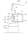
図1は、本発明の第1発明の巻取装置の一実施形態の側面図が示されている。巻取装置10は、ゴムテープGをリールRに渦巻き状に巻き取る装置である。巻取装置10は、本発明の第3発明の巻取方法に使用されうる。
Hereinafter, an embodiment of the present invention will be described with reference to the drawings.
FIG. 1 shows a side view of an embodiment of the winding device of the first invention of the present invention. The
ゴムテープGとは、例えば、タイヤの製造等に用いられる薄肉で長尺状のゴム成形体であり、その厚さ及び幅は特に限定されない。 The rubber tape G is, for example, a thin and long rubber molded body used for manufacturing tires, and the thickness and width thereof are not particularly limited.
巻取装置10は、ゴムテープGをリールRの近傍に供給する供給部11と、ゴムテープGの先端部G10に空気を吹き付ける送風部12と、送風部12を通過したゴムテープGをリールRに巻き取る巻取部13とを具える。
The
供給部11は、例えば、ゴムテープGをリールRに送り出すためのローラー11aを含む。供給部11によって第1工程が実施される。ローラー11aの回転軸は、リールRの回転軸と平行である。本実施形態では、ローラー11aは、リールRの上方に配設されている。従って、ローラー11aは、リールRの上方から鉛直下方向にゴムテープGを供給し、ローラー11aによって送り出されたゴムテープGの先端部G10は、リールRの外周面の側方に垂れ下がる。供給部11によってゴムテープGを供給する方向は、鉛直方向に限られず、水平方向又は斜め方向であってもよい。
The
ゴムテープGは、リールRの外周面に対向する第1面G11と、第1面G11とは反対側の第2面G12とを有する。 The rubber tape G has a first surface G11 facing the outer peripheral surface of the reel R, and a second surface G12 opposite to the first surface G11.
送風部12は、リールRの外周面の側方に配されている。送風部12によって、第2工程が実施される。送風部12は、ローラー11aによってリールRの外周面の側方まで送り出されたゴムテープGの先端部G10に対して、リールRとは反対側に配されている。すなわち、ゴムテープGの先端部G10は、リールRの外周面と送風部12との間に垂れ下がる。
The
送風部12は、圧縮された空気を吹き出すノズル12aと、ノズル12aに圧縮された空気を供給する配管12bとを有している。ノズル12aは、ゴムテープGの第2面G12と対向している。ノズル12aがゴムテープGの先端部G10に空気を吹き付けることにより、その風圧を受けた先端部G10がカールしてリールRに近づく。より具体的には、ノズル12aは、第2面G12からゴムテープGの厚さ方向に、空気を吹き出すことにより、先端部G10は、リールRの側にカールする。
The
配管12b内の空気の圧力は、0.5kPa以上が望ましい。配管12b内圧が0.5kPa以上に維持されることにより、先端部G10が短時間にカールしうる。
The pressure of air in the
巻取部13は、電動機等が内蔵された本体13aと、該本体13aに設けられたリールスタンド13bとを含んでいる。巻取部13によって第3工程が実施される。リールスタンド13bは、リールRの回転軸を水平に保持することができる。リールRは、交換可能である。また、リールスタンド13bは、保持されているリールRを所定の速度で回転駆動させる。即ち、本体13a電動機が駆動されることにより、リールRが回転し、供給部11から供給されるゴムテープGがリールRに連続的に巻き取られる。巻き取りスピードは、制御装置によって、供給部11の供給スピードと同期する。
The
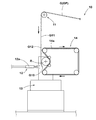
図2乃至5は、巻取装置10の動作を、時系列で示している。ゴムテープGの先端部G10がリールRの軸心よりも下方に達すると、ノズル12aは、ゴムテープGの先端部G10に、空気を吹き出す。これにより、風圧を受けたゴムテープGの先端部G10は、リールRの側にカールする。すなわち、ゴムテープGの先端部G10がリールRの外周面に沿う形状にカールすることにより、容易にリールRの外周面に巻き付けることが可能となり、巻き取りの作業効率が高められる。また、巻き取り時におけるゴムテープGの折れ曲がりが抑制され、均一な厚さのゴムテープGが得られる。このようなゴムテープGは、タイヤの製造精度の向上に寄与する。
2 to 5 show the operation of the winding
本実施形態の巻取部13は、ゴムテープGをリールRに押圧する押圧部14を含む。押圧部14は、スタンド等(図示せず)によって支持され、ゴムテープGの第2面G12をリールRの径方向内側に押圧し、第1面G11をリールRに当接させる。これにより、第1面G11とリールRとの間に摩擦力が生じ、ゴムテープGが回転駆動されるリールRに自動的に巻き取られる。
The winding
上述した巻取り初期工程は、作業者によって手動で実施される形態であってもよい。この場合、押圧部14は省略されうる。
The above-described initial winding process may be performed manually by an operator. In this case, the
押圧部14は、リールRに対して送風部12とは反対側に設けられているのが望ましい。これにより、送風部12から吹き出された空気は、押圧部14によって遮られることなく、ゴムテープGの先端部G10に吹き付けられる。
It is desirable that the
押圧部14は、リールRの外周面を含む周回軌道を無限に周回するベルト14aと、ベルト14aを周回軌道に保持する複数のローラー14bとを含む。各ローラー14bの回転軸は、リールRの回転軸と平行である。ローラー14bは、電動機等によって回転駆動され、ベルト14aを駆動する。ベルト14aは、リールRの回転方向とは逆方向に回転駆動される。
The
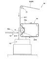
図3に示されるように、ゴムテープGの進行により先端部G10がベルト14aの外周面に達すると、先端部G10の第2面G12とベルト14aの外周面との間に摩擦が生じ、先端部G10は、ベルト14aによって駆動される。
As shown in FIG. 3, when the leading end G10 reaches the outer peripheral surface of the
その結果、図4に示されるように、ゴムテープGの先端部G10がリールRの外周面に引き込まれる。このとき、ゴムテープGの第1面G11とリールRの外周面との間に十分な摩擦力が生ずるまで、ノズル12aからの空気の吹き出しを継続するのが望ましい。そして、ゴムテープGの先端部G10がリールRの外周面に引き込まれた後は、ノズル12aからの空気の吹き出しは不要である。ゴムテープGの先端部G10とベルト14aの外周面との間で十分な摩擦が得られる場合は、先端部G10がベルト14aの外周面に達するまでノズル12aからの空気を吹き出すように構成されていてもよい。
As a result, as shown in FIG. 4, the front end G10 of the rubber tape G is drawn into the outer peripheral surface of the reel R. At this time, it is desirable to continue blowing air from the
ローラー14bの個数及び配置は、ベルト14aをリールRの外周面に沿って配置できる構成であれば、図示された形態に限られない。例えば、リールRの外周面に少なくとも1つのローラー14bを適宜配することにより、ゴムテープGの先端部G10を容易にリールRの外周面に引き込むことが可能となる。
The number and arrangement of the
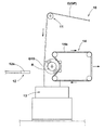
図4、5に示されるように、押圧部14は、ゴムテープGの巻取りの進行に応じて、リールRに対して後方に退避する。なお、押圧部14は、ゴムテープGの巻取りの初期段階のみ(例えば、ゴムテープGの先端部G10がリールRを一周するまで)、ゴムテープGをリールRに押圧し、その後退避するよう構成されていてもよい。
As shown in FIGS. 4 and 5, the
巻取装置10は、加硫されたゴムテープGの他、未加硫のゴムテープGの第1面G11にライナーが貼り合わせられてなるゴムテープ複合体GPの巻き取りにも適用可能である。ライナーは、第1面G11を保護すると共に、リールRに巻き取られたゴムテープGの第1面G11と第2面G12との固着を防止する。
In addition to the vulcanized rubber tape G, the winding
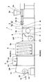
図6は、本発明の第2発明の製造装置の一実施形態の側面図が示されている。製造装置1は、ゴムテープGとライナーPとが貼り合わされてなるゴムテープ複合体GPを製造する装置である。 FIG. 6 shows a side view of an embodiment of the manufacturing apparatus of the second invention of the present invention. The production apparatus 1 is an apparatus for producing a rubber tape composite GP in which a rubber tape G and a liner P are bonded together.
製造装置1は、未加硫のゴムテープGを連続的に押し出す押出装置2と、押し出されたゴムテープGの第1面G11にライナーPを貼り合わせる貼合装置4と、巻取装置10とを具える。
The production apparatus 1 includes an
押出装置2は、例えば、未加硫の材料ゴムや各種の配合剤が投入される投入口2aが一端に設けられたシリンダ2bと、その中に収納されかつ回転駆動されるスクリュー軸2cと、スクリュー軸2cにて押し出された未加硫ゴムを断面略横長矩形状に吐出する口金を有する押出ヘッド2dとを含んで構成されている。なお、押出装置2の詳細な構成は、上記特許文献1に記載されているため、その説明は省略される。
The
貼合装置4は、本体4aと、複数のローラーrとを有する。また、貼合装置4には、樹脂材料からなるテープ状のライナーPの巻取物P1が装備されている。
The bonding apparatus 4 has a
貼合装置4の本体4aは、例えば、壁状に構成されている。本体4aには、水平な回転軸を有する多数のローラーrが片持ち状に軸支されている。
The
すなわち、本体4aには、押出装置2から押し出されたゴムテープGを下流側へと引き出すための駆動力を発生するローラーrと、引き出されたゴムテープGを冷却するクーリングドラムrcとが設けられている。
That is, the
クーリングドラムrcは、最も大きい径で形成された金属製のドラムである。該クーリングドラムrcは、押出しを経た比較的高温のゴムテープGと広い範囲で接触しかつこれを冷却する。クーリングドラムrcには、必要により、冷却水等の冷媒が循環され、その温度が低温に維持される。 The cooling drum rc is a metal drum formed with the largest diameter. The cooling drum rc contacts and cools a relatively high temperature rubber tape G that has been extruded through a wide range. If necessary, a coolant such as cooling water is circulated through the cooling drum rc, and the temperature thereof is maintained at a low temperature.
また、貼合装置4の本体4aには、樹脂材料からなるライナーPを巻き取った巻取物P1が装備されている。ライナーPは、例えば、ポリウレタン、ポリエステル、ポリエチレン、ポリ塩化ビニル又はポリスチレン等の樹脂材料からなり、薄いテープ状で形成されている。このライナーPは、予めリール等に渦巻き状に巻き取られている。この巻取物P1は、本体4aに着脱自在の軸支され、交換・再供給可能に取り付けられている。
Moreover, the
巻取物P1は、本体4aの回転自在に支持されている。巻取物P1から引き出されたライナーPは、ゴムテープGの持つ粘着力によって、第1面G11に貼り合わされる。これにより、ゴムテープGとライナーPとが貼り合わされたゴムテープ複合体GPが得られる。
The wound product P1 is rotatably supported by the
製造装置1によれば、ゴムテープ複合体GPをリールRに巻取る際の作業効率が高められ、ゴムテープ複合体GPを効率よく製造することが可能となる。 According to the manufacturing apparatus 1, the work efficiency at the time of winding the rubber tape composite GP on the reel R is enhanced, and the rubber tape composite GP can be efficiently manufactured.
製造装置1は、ゴムテープ複合体GPを切断する切断装置6をさらに具える。切断装置6は、ゴムテープ複合体GPを駆動するローラー61と、ゴムテープGをライナーPと共に切断するカッター62とを含んで構成されている。
The manufacturing apparatus 1 further includes a cutting device 6 that cuts the rubber tape composite GP. The cutting device 6 includes a
切断装置6は、リールRの交換にあたって、ゴムテープ複合体GPを切断する。切断装置6及び巻取装置10は、制御装置によって適宜同期して制御される。これにより、人手を介することなく、自動的にリールRが交換され、ゴムテープ複合体GPの生産効率が高められる。
The cutting device 6 cuts the rubber tape composite GP when replacing the reel R. The cutting device 6 and the winding
本実施形態の製造装置1は、押出装置2の先端部に設けられたカレンダーヘッド3と、貼合装置4と、切断装置6との間に設けられたフェスツーン装置5とを含んで構成されている。
The manufacturing apparatus 1 of this embodiment is configured to include a
カレンダーヘッド3は、ギャップを有して配された上下一対のカレンダーロール3a、3bを含む。各カレンダーロール3a、3bは、図示しない電動機にてそれぞれ逆向きに回動駆動可能に支持されている。押出装置2から吐出されたゴムは、連続して、カレンダーロール3a、3bのギャップを通過する。これにより、カレンダーロール3a、3bは、ゴムを圧延し、仕上げ断面形状を持ったゴムテープGを成形することができる。なお、カレンダーヘッド3の詳細な構成は、上記特許文献1に記載されているため、その説明は省略される。
The
フェスツーン装置5は、本体部5aと、ゴムテープ複合体GPの長手方向と直角かつ水平な軸心を有する複数のローラー5bとを含んで構成される。複数のローラー5bは、本体部5aの上部側に回転自在に軸支された上ローラー5b1と、本体部5aの下部側に回転自在に軸支されかつ上下に同期して移動可能な下ローラー5b2とを含んでいる。ゴムテープ複合体GPは、これらの上下のローラー5b1、5b2にジグザグ状に巻き掛けされている。
The
フェスツーン装置5は、下ローラー5b2が下方に移動することにより、ゴムテープ複合体GPを一時的に滞留させることができる。これにより、フェスツーン装置5は、例えば、リールRの交換時、連続供給されてくるゴムテープ複合体GPを吸収することができる。リールRの交換にあたって、フェスツーン装置5、切断装置6及び巻取装置10は、制御装置によって適宜同期して制御される。
The
以上、本発明の空気入りタイヤ及びその製造方法が詳細に説明されたが、本発明は上記の具体的な実施形態に限定されることなく種々の態様に変更して実施される。 As mentioned above, although the pneumatic tire of this invention and its manufacturing method were demonstrated in detail, this invention is changed and implemented in various aspects, without being limited to said specific embodiment.
1 製造装置
2 押出装置
4 貼合装置
6 切断装置
10 巻取装置
11 供給部
12 送風部
13 巻取部
14 押圧部
14a ベルト
G ゴムテープ
GP ゴムテープ複合体
G11 第1面
G12 第2面
P ライナー
R リール
DESCRIPTION OF SYMBOLS 1
Claims (9)
前記ゴムテープを前記リールの近傍に供給する供給部と、
前記ゴムテープの先端部に空気を吹き付けて、前記先端部を前記リールに近づける送風部と、
前記送風部を通過した前記ゴムテープを前記リールに巻き取る巻取部とを具えたことを特徴とするゴムテープの巻取装置。 A device for winding a rubber tape on a reel,
A supply unit for supplying the rubber tape to the vicinity of the reel;
A blower unit that blows air to the tip of the rubber tape to bring the tip close to the reel;
A rubber tape winding device comprising: a winding unit that winds the rubber tape that has passed through the blower unit around the reel.
未加硫の前記ゴムテープを連続的に押し出す押出装置と、押し出された前記ゴムテープの前記第1面にライナーを貼り合わせる貼合装置とを具えたことを特徴とするゴムテープ複合体の製造装置。 A rubber tape winding device according to claim 3;
An apparatus for producing a rubber tape composite comprising: an extrusion apparatus for continuously extruding the unvulcanized rubber tape; and a laminating apparatus for adhering a liner to the first surface of the extruded rubber tape.
前記ゴムテープを前記リールの近傍に供給する第1工程と、
前記ゴムテープの先端部に空気を吹き付けて、前記先端部を前記リールに近づける第2工程と、
前記第2工程を通過した前記ゴムテープを前記リールに巻き取る第3工程とを含むことを特徴とするゴムテープの巻取方法。 A method of winding an unvulcanized rubber tape on a reel,
A first step of supplying the rubber tape in the vicinity of the reel;
A second step of blowing air to a tip of the rubber tape to bring the tip close to the reel;
And a third step of winding the rubber tape that has passed through the second step onto the reel.
Priority Applications (1)
| Application Number | Priority Date | Filing Date | Title |
|---|---|---|---|
| JP2016100482A JP2017206366A (en) | 2016-05-19 | 2016-05-19 | Winding device of rubber tape, winding method and manufacturing apparatus of rubber tape composite |
Applications Claiming Priority (1)
| Application Number | Priority Date | Filing Date | Title |
|---|---|---|---|
| JP2016100482A JP2017206366A (en) | 2016-05-19 | 2016-05-19 | Winding device of rubber tape, winding method and manufacturing apparatus of rubber tape composite |
Publications (1)
| Publication Number | Publication Date |
|---|---|
| JP2017206366A true JP2017206366A (en) | 2017-11-24 |
Family
ID=60414701
Family Applications (1)
| Application Number | Title | Priority Date | Filing Date |
|---|---|---|---|
| JP2016100482A Pending JP2017206366A (en) | 2016-05-19 | 2016-05-19 | Winding device of rubber tape, winding method and manufacturing apparatus of rubber tape composite |
Country Status (1)
| Country | Link |
|---|---|
| JP (1) | JP2017206366A (en) |
Cited By (1)
| Publication number | Priority date | Publication date | Assignee | Title |
|---|---|---|---|---|
| JP2019182619A (en) * | 2018-04-12 | 2019-10-24 | 株式会社小林製作所 | Method and apparatus for winding substrate |
-
2016
- 2016-05-19 JP JP2016100482A patent/JP2017206366A/en active Pending
Cited By (1)
| Publication number | Priority date | Publication date | Assignee | Title |
|---|---|---|---|---|
| JP2019182619A (en) * | 2018-04-12 | 2019-10-24 | 株式会社小林製作所 | Method and apparatus for winding substrate |
Similar Documents
| Publication | Publication Date | Title |
|---|---|---|
| JP4941610B1 (en) | Rubber roll manufacturing apparatus and rubber roll manufacturing method | |
| JP5628168B2 (en) | Method and apparatus for the production of polymer films stretched at an angle to the length direction | |
| US7622013B2 (en) | Tire manufacturing method, cover rubber stamping device used therefore, tire, as well as rubber sheet member stamping method, and device | |
| JP6018868B2 (en) | Rubber strip manufacturing apparatus and manufacturing method | |
| CN109228423B (en) | Production and processing method of CPP film | |
| JP2010508172A (en) | Method and apparatus for manufacturing pneumatic tires | |
| JP6082220B2 (en) | Rubber strip sticking device | |
| JP2017206366A (en) | Winding device of rubber tape, winding method and manufacturing apparatus of rubber tape composite | |
| JP6063692B2 (en) | Rubber strip pasting device | |
| JP4205055B2 (en) | Tire component sticking apparatus and sticking method | |
| JP2004358738A (en) | Continuous molding equipment for strip rubber and continuous molding method using it | |
| JP2008126560A (en) | Rubber molding machine, method and apparatus for producing rubber member | |
| JP5210128B2 (en) | Tire manufacturing apparatus and tire manufacturing method | |
| JP2007106354A (en) | Pneumatic tire, and method and apparatus for molding tire | |
| JP2010023338A (en) | Device for forming rubber member and forming process | |
| CN206395530U (en) | A kind of Hot rolling non-woven fabrics former high-speed winding device | |
| JP2008307749A (en) | Method and apparatus for manufacturing retreaded tire | |
| JP2019051670A (en) | Bead core coating method and bead core coating apparatus | |
| JP6572554B2 (en) | Rubber strip manufacturing equipment | |
| JPH05301299A (en) | Continuous manufacture and its device of conveyor belt | |
| JP2008119993A (en) | Laminating method and laminating apparatus for ribbon-form rubber, and manufacturing apparatus for rubber member | |
| JP6741515B2 (en) | Bead core coating method and bead core coating apparatus | |
| JP2009143165A (en) | Manufacturing method and manufacturing apparatus for tire | |
| JP7218491B2 (en) | Green tire manufacturing apparatus and green tire manufacturing method | |
| JP6765996B2 (en) | Rubber member manufacturing method and manufacturing equipment |