JP2017206182A - Automatic drive support device and computer program - Google Patents
Automatic drive support device and computer program Download PDFInfo
- Publication number
- JP2017206182A JP2017206182A JP2016101235A JP2016101235A JP2017206182A JP 2017206182 A JP2017206182 A JP 2017206182A JP 2016101235 A JP2016101235 A JP 2016101235A JP 2016101235 A JP2016101235 A JP 2016101235A JP 2017206182 A JP2017206182 A JP 2017206182A
- Authority
- JP
- Japan
- Prior art keywords
- trajectory
- vehicle
- control
- automatic driving
- travel
- Prior art date
- Legal status (The legal status is an assumption and is not a legal conclusion. Google has not performed a legal analysis and makes no representation as to the accuracy of the status listed.)
- Granted
Links
Images


Abstract
Description
本発明は、車両において自動運転支援を行う自動運転支援装置及びコンピュータプログラムに関する。 The present invention relates to an automatic driving support apparatus and a computer program that perform automatic driving support in a vehicle.
近年、車両の走行形態として、ユーザの運転操作に基づいて走行する手動走行以外に、ユーザの運転操作の一部又は全てを車両側で実行することにより、ユーザによる車両の運転を補助する自動運転支援システムについて新たに提案されている。自動運転支援システムでは、例えば、車両の現在位置、車両が走行する車線、周辺の他車両の位置を随時検出し、予め設定された経路に沿って走行するようにステアリング、駆動源、ブレーキ等の車両制御が自動で行われる。 In recent years, automatic driving that assists the user in driving the vehicle by executing part or all of the user's driving operation on the vehicle side, in addition to manual driving that travels based on the user's driving operation, as the driving mode of the vehicle. A new support system has been proposed. In the automatic driving support system, for example, the current position of the vehicle, the lane in which the vehicle travels, the positions of other vehicles in the vicinity are detected at any time, and the steering, drive source, brake, etc. Vehicle control is performed automatically.
また、自動運転支援による走行は基本的に予め決められた目標走行軌道(例えば車両が走行すべき車線の中心線)にできる限り沿って車両を走行させる制御を行う。例えば、特開2013−112067号公報には、車両の走行位置が目標走行軌道である走行進路上に所定間隔で配置された目標通過点の内、自車の現在位置から所定範囲内にある目標通過点を固定目標通過点として設定し、車両の現在位置から固定目標通過点を通過する走行進路を生成する技術について提案されている。 In addition, the driving by the automatic driving support basically performs control for driving the vehicle as much as possible along a predetermined target traveling track (for example, the center line of the lane on which the vehicle should travel). For example, Japanese Patent Laid-Open No. 2013-112067 discloses a target that is within a predetermined range from the current position of the host vehicle among target passing points that are arranged at predetermined intervals on a travel route where the travel position of the vehicle is a target travel path. There has been proposed a technique for setting a passing point as a fixed target passing point and generating a traveling route that passes through the fixed target passing point from the current position of the vehicle.
ここで、車両が走行する道路上には他車両、駐車車両、歩行者等の様々な障害物が存在する。従って、自動運転支援による走行ではそれらの障害物を考慮した走行を行う必要がある。しかしながら、上記特開2013−112067号公報では、自車の現在位置から所定範囲内にある固定目標通過点を通過する軌道を走行進路としていることから、車両と固定目標通過点とを繋ぐ走行進路上に障害物を検出した場合には、障害物を回避する走行進路を新たに生成することが難しく、車両の停止制御を行っていた(特許文献1の段落0084〜0086)。 Here, there are various obstacles such as other vehicles, parked vehicles, and pedestrians on the road on which the vehicle travels. Therefore, it is necessary to travel in consideration of these obstacles when traveling with automatic driving assistance. However, in the above Japanese Patent Laid-Open No. 2013-112067, a trajectory that passes through a fixed target passing point that is within a predetermined range from the current position of the host vehicle is used as a traveling route, and therefore a traveling path that connects the vehicle and the fixed target passing point. When an obstacle is detected above, it is difficult to newly generate a traveling route that avoids the obstacle, and vehicle stop control is performed (paragraphs 0084 to 0086 of Patent Document 1).
しかしながら、自動運転支援による走行はユーザの運転に係る負担を軽減できるメリットがあるが、車両の停止制御を行うことなしにできる限り継続して走行させるのが望ましい。 However, although traveling by automatic driving assistance has an advantage that the burden on the user's driving can be reduced, it is desirable that the traveling is continued as much as possible without performing stop control of the vehicle.
本発明は前記従来における問題点を解消するためになされたものであり、自動運転支援による車両の走行が行われている場合において、障害物を回避する制御軌道を生成することが可能であり、自動運転支援を適切に継続して実施することを可能にした自動運転支援装置及びコンピュータプログラムを提供することを目的とする。 The present invention has been made to solve the problems in the prior art, it is possible to generate a control trajectory that avoids obstacles when the vehicle is running with automatic driving assistance, An object of the present invention is to provide an automatic driving support device and a computer program that can appropriately and continuously carry out automatic driving support.
前記目的を達成するため本発明に係る自動運転支援装置は、車両において実施する自動運転支援に用いる支援情報を生成する自動運転支援装置であって、車両が走行する道路に対して目標とする走行軌道である目標走行軌道を設定する走行軌道設定手段と、障害物を検出する障害物検出手段と、前記目標走行軌道上であって軌道生成開始点から進行方向前方の位置に、前記障害物を回避する制御目標地点を設定する制御目標地点設定手段と、前記軌道生成開始点から前記制御目標地点へと走行する軌道を用いて、車両に走行させる制御軌道を生成する制御軌道生成手段と、を有する。
尚、「自動運転支援」とは、運転者の車両操作の少なくとも一部を運転者に代わって行う又は補助する機能をいう。
In order to achieve the above object, an automatic driving support apparatus according to the present invention is an automatic driving support apparatus that generates support information used for automatic driving support performed in a vehicle, and is a target driving for a road on which the vehicle runs. A travel trajectory setting means for setting a target travel trajectory that is a trajectory; an obstacle detection means for detecting an obstacle; and the obstacle on the target travel trajectory and at a position ahead of the trajectory generation direction from the trajectory generation start point. Control target point setting means for setting a control target point to be avoided, and control trajectory generation means for generating a control trajectory for causing the vehicle to travel using a trajectory that travels from the trajectory generation start point to the control target point. Have.
Note that “automatic driving assistance” refers to a function of performing or assisting at least a part of the driver's vehicle operation on behalf of the driver.
また、本発明に係るコンピュータプログラムは、車両において実施する自動運転支援に用いる支援情報を生成するプログラムである。具体的には、コンピュータを、車両が走行する道路に対して目標とする走行軌道である目標走行軌道を設定する走行軌道設定手段と、障害物を検出する障害物検出手段と、前記目標走行軌道上であって軌道生成開始点から進行方向前方の位置に、前記障害物を回避する制御目標地点を設定する制御目標地点設定手段と、前記軌道生成開始点から前記制御目標地点へと走行する軌道を用いて、車両に走行させる制御軌道を生成する制御軌道生成手段と、して機能させる。 The computer program according to the present invention is a program that generates support information used for automatic driving support performed in a vehicle. Specifically, the computer sets traveling trajectory setting means for setting a target traveling trajectory that is a target traveling trajectory for a road on which the vehicle travels, obstacle detecting means for detecting an obstacle, and the target traveling trajectory. Control target point setting means for setting a control target point for avoiding the obstacle at a position ahead of the trajectory generation start point and a trajectory that travels from the trajectory generation start point to the control target point Is used as a control trajectory generating means for generating a control trajectory for the vehicle to travel.
前記構成を有する本発明に係る自動運転支援装置及びコンピュータプログラムによれば、自動運転支援による車両の走行が行われている場合において、障害物を回避する制御軌道を生成することが可能となる。従って、障害物が存在した場合であっても自動運転支援による走行を車両の停止制御を行うことなしにできる限り継続して行うことが可能である。 According to the automatic driving assistance apparatus and the computer program according to the present invention having the above-described configuration, it is possible to generate a control trajectory that avoids an obstacle when the vehicle is traveling by automatic driving assistance. Therefore, even if there is an obstacle, it is possible to continue traveling as much as possible without performing stop control of the vehicle, even if there is an obstacle.
以下、本発明に係る自動運転支援装置を、ナビゲーション装置に具体化した一実施形態に基づき図面を参照しつつ詳細に説明する。先ず、本実施形態に係るナビゲーション装置1の概略構成について図1を用いて説明する。図1は本実施形態に係るナビゲーション装置1を示したブロック図である。
Hereinafter, an automatic driving support device according to the present invention will be described in detail with reference to the drawings based on an embodiment embodied in a navigation device. First, a schematic configuration of the
図1に示すように本実施形態に係るナビゲーション装置1は、ナビゲーション装置1が搭載された車両の現在位置を検出する現在位置検出部11と、各種のデータが記録されたデータ記録部12と、入力された情報に基づいて、各種の演算処理を行うナビゲーションECU13と、ユーザからの操作を受け付ける操作部14と、ユーザに対して車両周辺の地図やナビゲーション装置1で設定されている案内経路(車両の走行予定経路)に関する情報等を表示する液晶ディスプレイ15と、経路案内に関する音声ガイダンスを出力するスピーカ16と、記憶媒体であるDVDを読み取るDVDドライブ17と、プローブセンタやVICS(登録商標:Vehicle Information and Communication System)センタ等の情報センタとの間で通信を行う通信モジュール18と、を有する。また、ナビゲーション装置1はCAN等の車載ネットワークを介して、ナビゲーション装置1の搭載された車両に対して設置された車外カメラ19や各種センサが接続されている。更に、ナビゲーション装置1の搭載された車両に対する各種制御を行う車両制御ECU20とも双方向通信可能に接続されている。また、自動運転開始ボタン等の車両に搭載された各種操作ボタン21についても接続されている。
As shown in FIG. 1, the
以下に、ナビゲーション装置1が有する各構成要素について順に説明する。
現在位置検出部11は、GPS22、車速センサ23、ステアリングセンサ24、ジャイロセンサ25等からなり、現在の車両の位置、方位、車両の走行速度、現在時刻等を検出することが可能となっている。ここで、特に車速センサ23は、車両の移動距離や車速を検出する為のセンサであり、車両の駆動輪の回転に応じてパルスを発生させ、パルス信号をナビゲーションECU13に出力する。そして、ナビゲーションECU13は発生するパルスを計数することにより駆動輪の回転速度や移動距離を算出する。尚、上記4種類のセンサをナビゲーション装置1が全て備える必要はなく、これらの内の1又は複数種類のセンサのみをナビゲーション装置1が備える構成としても良い。
Below, each component which the
The current
また、データ記録部12は、外部記憶装置及び記録媒体としてのハードディスク(図示せず)と、ハードディスクに記録された地図情報DB31や障害物情報DB32や所定のプログラム等を読み出すとともにハードディスクに所定のデータを書き込む為のドライバである記録ヘッド(図示せず)とを備えている。尚、データ記録部12をハードディスクの代わりにフラッシュメモリやメモリーカードやCDやDVD等の光ディスクを有しても良い。また、地図情報DB31は外部のサーバに格納させ、ナビゲーション装置1が通信により取得する構成としても良い。
In addition, the
ここで、地図情報DB31は、例えば、道路(リンク)に関するリンクデータ34、ノード点に関するノードデータ35、経路の探索や変更に係る処理に用いられる探索データ36、施設に関する施設データ、地図を表示するための地図表示データ、各交差点に関する交差点データ、地点を検索するための検索データ等が記憶された記憶手段である。
Here, the
また、リンクデータ34としては、道路を構成する各リンクに関してリンクの属する道路の幅員、勾(こう)配、カント、バンク、路面の状態、ノード間のリンク形状(例えばカーブ道路ではカーブの形状)を特定する為の形状補完点データ、合流区間、道路構造、道路の車線数、車線数の減少する箇所、幅員の狭くなる箇所、踏切り等を表すデータが、コーナに関して、曲率半径、交差点、T字路、コーナの入口及び出口等を表すデータが、道路属性に関して、降坂路、登坂路等を表すデータが、道路種別に関して、国道、県道、細街路等の一般道のほか、高速自動車国道、都市高速道路、自動車専用道路、一般有料道路、有料橋等の有料道路を表すデータがそれぞれ記録される。特に本実施形態では、道路の車線数に加えて、車線毎の進行方向の通行区分や道路の繋がり(具体的には、分岐においてどの車線がどの道路に接続されているか)を特定する情報についても記憶されている。更に、道路に設定されている制限速度についても記憶されている。
The
また、ノードデータ35としては、実際の道路の分岐点(交差点、T字路等も含む)や各道路に曲率半径等に応じて所定の距離毎に設定されたノード点の座標(位置)、ノードが交差点に対応するノードであるか等を表すノード属性、ノードに接続するリンクのリンク番号のリストである接続リンク番号リスト、ノードにリンクを介して隣接するノードのノード番号のリストである隣接ノード番号リスト、各ノード点の高さ(高度)等に関するデータ等が記録される。
Further, as the
また、探索データ36としては、出発地(例えば車両の現在位置)から設定された目的地までの経路を探索する経路探索処理に使用される各種データについて記録されている。具体的には、交差点に対する経路として適正の程度を数値化したコスト(以下、交差点コストという)や道路を構成するリンクに対する経路として適正の程度を数値化したコスト(以下、リンクコストという)等の探索コストを算出する為に使用するコスト算出データが記憶されている。
In addition, as the
また、障害物情報DB32は、外部のサーバによって配信された障害物に関する障害物情報が記憶される記憶手段である。また、自車両の車外カメラ19やセンサによって検出した自車両の周囲に位置する障害物に関する障害物情報についても記憶される。ここで、障害物情報DB32に障害物情報が記憶される障害物は、車両において後述のように実施される自動運転支援に影響する対象物(要因)であり、例えば周辺を走行する他車両、路上に停車する駐車車両、工事区間、渋滞車両等が該当する。また、障害物情報は例えば障害物の種類と、障害物の地図上の位置座標(範囲に跨る場合には形状(占有領域)を特定する情報)と、障害物が特に移動体である場合には移動方向や移動速度とを含む。そして、ナビゲーションECU13は、後述のように地図情報DB31に記憶された地図情報や障害物情報DB32に記憶された障害物情報を用いて自動運転支援を実施する。
The
ここで、車両の走行形態としては、ユーザの運転操作に基づいて走行する手動運転走行に加えて、ユーザの運転操作によらず車両が予め設定された経路や道なりに沿って自動的に走行を行う自動運転支援による支援走行が可能である。尚、自動運転支援における車両制御では、例えば、車両の現在位置、車両が走行する車線、周辺の障害物の位置を随時検出し、車両制御ECU20によって予め設定された経路に沿って走行するようにステアリング、駆動源、ブレーキ等の車両制御が自動で行われる。尚、本実施形態の自動運転支援による支援走行では、車線変更や右左折についても自動運転制御により行う構成とするが、車線変更や右左折の一部については自動運転制御では行わない構成としても良い。
Here, as a traveling form of the vehicle, in addition to the manual driving traveling that travels based on the user's driving operation, the vehicle automatically travels along a predetermined route or road regardless of the user's driving operation. Assisted driving with automatic driving assistance is possible. In the vehicle control in the automatic driving support, for example, the current position of the vehicle, the lane in which the vehicle travels, and the positions of surrounding obstacles are detected at any time, and the
具体的に本実施形態では、右左折、合流、分岐等の特殊な状況下を除いて基本的に以下の2種類のいずれかの自動運転支援を行う。
(1)『車線維持走行支援』・・・車両が車線を逸脱することなく車線の中心付近を走行させる制御(例えばレーン・キーピング・アシスト)。
(2)『車線変更支援』・・・現在走行する車線から異なる車線へと移動させる制御。
尚、上記(1)、(2)のいずれの支援を実施するかは、車両が走行する道路に対して設定された目標とする走行軌道である目標走行軌道に基づいて決定される。また、上記(1)、(2)の制御と平行して、前方車両との車間距離を一定距離(例えば10m)に保つ制御や一定速度(例えば制限速度の80%)で走行する制御等についても実施される。
Specifically, in the present embodiment, any one of the following two types of automatic driving assistance is basically performed except under special circumstances such as turning left and right, joining, and branching.
(1) “Lane maintenance support”: Control in which the vehicle travels near the center of the lane without departing from the lane (for example, lane keeping assist).
(2) “Lane change support”: Control for moving from the currently traveling lane to a different lane.
It should be noted that which of the above assistances (1) and (2) is to be implemented is determined based on a target travel path that is a target travel path set for a road on which the vehicle travels. In parallel with the controls (1) and (2) above, control for keeping the distance between the vehicle and the vehicle ahead is constant (for example, 10 m), control for traveling at a constant speed (for example, 80% of the limit speed), etc. Is also implemented.
また、自動運転支援は全ての道路区間に対して行っても良いし、特定の道路区間(例えば境界にゲート(有人無人、有料無料は問わない)が設けられた高速道路)を車両が走行する間のみ行う構成としても良い。以下の説明では車両の自動運転支援が行われる自動運転区間は、一般道や高速道路を含む全ての道路区間とし、車両が道路上を走行する間において基本的に上記自動運転支援が行われるとして説明する。但し、車両が自動運転区間を走行する場合には必ず自動運転支援が行われるのではなく、ユーザにより自動運転支援を行うことが選択され(例えば自動運転開始ボタンをONする)、且つ自動運転支援による走行を行わせることが可能と判定された状況でのみ行われる。尚、自動運転支援の詳細については後述する。 In addition, the automatic driving support may be performed for all road sections, or the vehicle travels on a specific road section (for example, a highway with a gate (whether manned or unpaid) regardless of whether it is manned or paid). It is good also as a structure performed only between. In the following description, it is assumed that the automatic driving section in which the automatic driving support of the vehicle is performed is all road sections including general roads and highways, and the automatic driving support is basically performed while the vehicle travels on the road. explain. However, when the vehicle travels in an automatic driving section, automatic driving support is not always performed, but automatic driving support is selected by the user (for example, an automatic driving start button is turned on), and automatic driving support is performed. It is performed only in a situation where it is determined that it is possible to cause the vehicle to travel. Details of the automatic driving support will be described later.
一方、ナビゲーションECU(エレクトロニック・コントロール・ユニット)13は、ナビゲーション装置1の全体の制御を行う電子制御ユニットであり、演算装置及び制御装置としてのCPU41、並びにCPU41が各種の演算処理を行うにあたってワーキングメモリとして使用されるとともに、経路が探索されたときの経路データ等が記憶されるRAM42、制御用のプログラムのほか、後述の自動運転支援プログラム(図2参照)等が記録されたROM43、ROM43から読み出したプログラムを記憶するフラッシュメモリ44等の内部記憶装置を備えている。尚、ナビゲーションECU13は、処理アルゴリズムとしての各種手段を有する。例えば、走行軌道設定手段は、車両が走行する道路に対して目標とする走行軌道である目標走行軌道を設定する。障害物検出手段は、障害物を検出する。制御目標地点設定手段は、目標走行軌道上であって軌道生成開始点から進行方向前方の位置に、障害物を回避する制御目標地点を設定する。制御軌道生成手段は、軌道生成開始点から制御目標地点へと走行する軌道を用いて、車両に走行させる制御軌道を生成する。
On the other hand, the navigation ECU (Electronic Control Unit) 13 is an electronic control unit that controls the
操作部14は、走行開始地点としての出発地及び走行終了地点としての目的地を入力する際等に操作され、各種のキー、ボタン等の複数の操作スイッチ(図示せず)を有する。そして、ナビゲーションECU13は、各スイッチの押下等により出力されるスイッチ信号に基づき、対応する各種の動作を実行すべく制御を行う。尚、操作部14は液晶ディスプレイ15の前面に設けたタッチパネルを有しても良い。また、マイクと音声認識装置を有しても良い。
The
また、液晶ディスプレイ15には、道路を含む地図画像、交通情報、操作案内、操作メニュー、キーの案内、案内経路に沿った案内情報、ニュース、天気予報、時刻、メール、テレビ番組等が表示される。尚、液晶ディスプレイ15の代わりに、HUDやHMDを用いても良い。
The
また、スピーカ16は、ナビゲーションECU13からの指示に基づいて案内経路に沿った走行を案内する音声ガイダンスや、交通情報の案内を出力する。
The
また、DVDドライブ17は、DVDやCD等の記録媒体に記録されたデータを読み取り可能なドライブである。そして、読み取ったデータに基づいて音楽や映像の再生、地図情報DB31の更新等が行われる。尚、DVDドライブ17に替えてメモリーカードを読み書きする為のカードスロットを設けても良い。
The
また、通信モジュール18は、交通情報センタ、例えば、VICSセンタやプローブセンタ等から送信された交通情報、プローブ情報、天候情報等を受信する為の通信装置であり、例えば携帯電話機やDCMが該当する。また、車車間で通信を行う車車間通信装置や路側機との間で通信を行う路車間通信装置も含む。
The
また、車外カメラ19は、例えばCCD等の固体撮像素子を用いたカメラにより構成され、車両のフロントバンパの上方に取り付けられるとともに光軸方向を水平より所定角度下方に向けて設置される。そして、車外カメラ19は、車両が自動運転区間を走行する場合において、車両の進行方向前方を撮像する。また、車両制御ECU20は撮像された撮像画像に対して画像処理を行うことによって、車両が走行する道路に描かれた区画線や周辺の他車両等の障害物を検出し、検出結果に基づいて車両の自動運転支援を行う。尚、車外カメラ19は車両前方以外に後方や側方に配置するように構成しても良い。また、障害物を検出する手段としてはカメラの代わりにミリ波レーダやレーザセンサ等のセンサや車車間通信や路車間通信を用いても良い。
The
また、車両制御ECU20は、ナビゲーション装置1が搭載された車両の制御を行う電子制御ユニットである。また、車両制御ECU20にはステアリング、ブレーキ、アクセル等の車両の各駆動部と接続されており、本実施形態では特に車両において自動運転支援が開始された後に、各駆動部を制御することにより車両の自動運転支援を実施する。また、自動運転支援中にユーザによってオーバーライドが行われた場合には、オーバーライドが行われたことを検出する。
The
ここで、ナビゲーションECU13は、走行開始後にCANを介して車両制御ECU20に対して自動運転支援に関する指示信号を送信する。そして、車両制御ECU20は受信した指示信号に応じて走行開始後の自動運転支援を実施する。尚、指示信号の内容は、車両が走行する軌道や走行車速等を指示する情報である。 Here, navigation ECU13 transmits the instruction | indication signal regarding automatic driving assistance with respect to vehicle control ECU20 via CAN after a driving | running | working start. And vehicle control ECU20 implements the automatic driving assistance after a driving | running | working start according to the received instruction signal. Note that the content of the instruction signal is information for instructing a track on which the vehicle travels, a traveling vehicle speed, and the like.
続いて、上記構成を有する本実施形態に係るナビゲーション装置1においてCPU41が実行する自動運転支援プログラムについて図2に基づき説明する。図2は本実施形態に係る自動運転支援プログラムのフローチャートである。ここで、自動運転支援プログラムは、車両のACC電源(accessory power supply)がONされた後であって自動運転支援による車両の走行が開始された場合に実行され、設定された目標走行軌道に沿って走行する為の車両の自動運転支援を実施するプログラムである。また、以下の図2、図5、図9、図10及び図18にフローチャートで示されるプログラムは、ナビゲーション装置1が備えているRAM42やROM43に記憶されており、CPU41により実行される。
Next, an automatic driving support program executed by the
先ず、自動運転支援プログラムではステップ(以下、Sと略記する)1において、CPU41は、車両が今後走行する予定にある経路(以下、走行予定経路という)を取得する。尚、車両の走行予定経路は、ナビゲーション装置1において案内経路が設定されている場合には、ナビゲーション装置1において現在設定されている案内経路の内、車両の現在位置から目的地までの経路を走行予定経路とする。尚、案内経路はナビゲーション装置1によって設定された出発地から目的地までの推奨経路であり、例えば公知のダイクストラ法を用いて探索される。一方、ナビゲーション装置1において案内経路が設定されていない場合には、車両の現在位置から道なりに走行する経路を走行予定経路とする。
First, in step (hereinafter abbreviated as S) 1 in the automatic driving support program, the
次に、S2においてCPU41は、地図情報DB31から走行予定経路の車線に関する車線情報を取得する。具体的には、走行予定経路を構成する道路に含まれる車線数、車線毎の進行方向の通行区分や道路の繋がり(分岐においてどの車線がどの道路に接続されているか)を特定する情報が取得される。
Next, in S <b> 2, the
続いて、S3においてCPU41は、前記S1で取得した走行予定経路と前記S2で取得した車線情報とに基づいて、今後に車両が走行する道路に対して目標とする走行軌道である目標走行軌道50を設定する。尚、目標走行軌道50は、基本的には走行予定経路を構成する道路に含まれる車線の内、走行が推奨される車線の中心線に対して車両の進行方向に沿って設定される。例えば、図3に示す例では片側2車線の道路を車両が道なりに走行する場合であり、走行が推奨される左側の車線の中心線に対して目標走行軌道50が設定される。一方で、図4に示す例では、車線が左側に新たに増加する場合であって、車両がその後に左折又は左分岐する場合であり、車線の増加地点までは左側の車線の中心線に対して目標走行軌道50が設定され、車線が増加した後は増加した車線の中心線に対して目標走行軌道50が設定される。尚、走行予定経路の全経路を対象として上記目標走行軌道を設定しても良いが、車両の現在位置から所定距離(例えば300m)以内のみを対象として上記目標走行軌道を設定しても良い。その場合には、上記S1〜S3の処理は車両が所定距離走行する度に繰り返し実施される。
Subsequently, in S3, the
次に、S4においてCPU41は、前回の除外範囲距離を示すパラメータXn−1に初期値を設定する。初期値は例えば5mとするが、その値は適宜変更可能である。車両において現在実施されている自動運転支援の支援内容に基づいて初期値を変更しても良い。ここで、除外範囲距離は後述のように車両に走行させる制御軌道を生成する際(S6)に用いられるパラメータである。詳細については後述する。尚、パラメータXn−1はRAM42等に記憶される。
Next, in S4, the
以下のS5〜S9の処理は、車両のACC電源(accessory power supply)がONされている間において一定周期(例えば100msec)毎に繰り返し実行される。そして、車両のACC電源がOFFされた後に当該自動運転支援プログラムを終了する。 The following processes of S5 to S9 are repeatedly executed at regular intervals (for example, 100 msec) while the ACC power supply (accessory power supply) of the vehicle is ON. Then, after the ACC power supply of the vehicle is turned off, the automatic driving support program ends.
先ず、S5においてCPU41は現在の車両において自動運転支援が実施されているか否かを判定する。尚、自動運転支援は例えばユーザによる自動運転開始ボタン等の操作によって実施のON/OFFを切り替えることが可能である。また、自動運転支援を実施することが困難な状況(例えば車両が走行する車線を区画する区画線が消失した場合等)となった際に実施が中止される場合もある。
First, in S5, the
そして、自動運転支援が実施されていると判定された場合(S5:YES)には、S6へと移行する。それに対して、自動運転支援が実施されていないと判定された場合(S5:NO)には、制御軌道の生成や生成された制御軌道に基づく自動運転支援を行うことなく当該自動運転支援プログラムを終了する。 And when it determines with automatic driving assistance being implemented (S5: YES), it transfers to S6. On the other hand, when it is determined that the automatic driving support is not implemented (S5: NO), the automatic driving support program is executed without generating the control trajectory or the automatic driving support based on the generated control trajectory. finish.
S6においてCPU41は、後述の制御軌道生成処理(図5)を実行する。ここで、制御軌道生成処理は、今後に車両に走行させる軌道である制御軌道を生成する処理である。尚、制御軌道は後述のように車両の現在位置から進行方向に沿って停止距離(運転者がブレーキをかけると判断してから停止するまでに必要な距離)前方までの区間を対象として生成される。また、制御軌道は前記S3で設定された目標走行軌道にできる限り沿って走行する為の軌道であり、例えば車両の現在位置が目標走行軌道上又は周辺にある場合には、継続して目標走行軌道周辺に留まる軌道となり、一方で車両の現在位置が目標走行軌道から外れていた場合には、目標走行軌道上へと向かう軌道となる。
In S6, the
続いて、S7においてCPU41は、RAM42に格納された前回の除外範囲距離を示すパラメータXn−1を読み出し、直近に実施された前記S6で制御軌道を生成するのに用いられた除外範囲距離Xnの内、特に最初(走行時刻が0)に設定された除外範囲距離Xnを代入する。
Subsequently, in S7, the
次に、S8においてCPU41は、前記S6で生成された制御軌道に沿って車両が走行する為の制御量を演算する。具体的には、アクセル、ブレーキ、ギヤ及びステアリングの制御量が夫々演算される。
Next, in S8, the
その後、S9においてCPU41は、S8において演算された制御量を反映する。具体的には、演算された制御量を、CANを介して車両制御ECU20へと送信する。車両制御ECU20では受信した制御量に基づいてアクセル、ブレーキ、ギヤ及びステアリングの各車両制御が行われる。その結果、車両が生成された制御軌道に沿って走行する走行支援制御が可能となる。
Thereafter, in S9, the
そして、一定周期(例えば100msec)毎に上記S5〜S9の処理を繰り返し実行することによって、直近に検出された車両の現在位置や方位から目標走行軌道に沿って走行させる為の最適な制御軌道の生成及び制御軌道に沿って走行させる為の自動運転支援を実施することが可能となる。 Then, by repeatedly executing the processing of S5 to S9 at regular intervals (for example, 100 msec), an optimal control trajectory for traveling along the target travel trajectory from the most recently detected vehicle current position and direction is obtained. It is possible to implement automatic driving support for traveling along the generation and control trajectory.
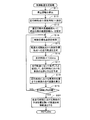
次に、前記S6において実行される制御軌道生成処理のサブ処理について図5に基づき説明する。図5は制御軌道生成処理のサブ処理プログラムのフローチャートである。 Next, the sub-process of the control trajectory generation process executed in S6 will be described with reference to FIG. FIG. 5 is a flowchart of a sub-processing program for the control trajectory generation process.
先ず、S11においてCPU41は、車両の現在の車速から現在の車両の“停止距離”を算出する。尚、“停止距離”は運転者がブレーキをかけると判断してから停止するまでに必要な距離であり、空走距離に0.2Gの減速度で停止する為の制動距離を加算した距離とする。尚、停止距離の具体的な算出方法については公知であるので詳細は省略する。
First, in S11, the
次に、S12においてCPU41は、パラメータである走行時刻tに初期値として0(0は現在時刻を意味する)を設定する。尚、走行時刻tはRAM42等に記憶される。
Next, in S <b> 12, the
続いて、S13においてCPU41は、直近の除外範囲距離を示すパラメータXt−1に前回の除外範囲距離を示すパラメータXn−1を代入する。尚、前回の除外範囲距離を示すパラメータXn−1は前記S4又はS7で設定される。尚、パラメータXt−1はRAM42等に記憶される。
Subsequently, in S13, the
その後、S14においてCPU41は、後述の制御目標地点設定処理(図9、図10)を実行する。ここで、制御目標地点設定処理は、制御軌道を生成する際の目標点である制御目標地点を設定する処理である。尚、制御目標地点は、後述のように目標走行軌道上であって軌道生成開始点から車両において実施されている自動運転支援の支援内容に基づく距離だけ進行方向前方の位置に設定される。更に、目標走行軌道の周辺に障害物が存在する場合には、障害物を回避可能な位置に設定される。また、軌道生成開始点は現時点の走行時刻t(現在時刻からt時間後)において予測される車両の位置であり、後述のS17で特定される。特に走行時刻tが初期値である0の場合は、軌道生成開始点は車両の現在位置となる。
Thereafter, in S14, the
次に、S15においてCPU41は、軌道生成開始点から前記S14で設定された制御目標地点までの軌道(以下、走行軌道という)を生成する。具体的には車両が軌道生成開始点から制御目標地点までを、現在の車速で所定の操舵角以内で走行する軌道を走行軌道として生成する。また、軌道生成開始点は現時点の走行時刻t(現在時刻からt時間後)において予測される車両の位置である。また、軌道生成開始点における車両の方位は後述のS17で特定される。
Next, in S15, the
その後、S16においてCPU41は、RAM42から走行時刻tを読み出し、100msec加算する。
Thereafter, in S16, the
続いて、S17においてCPU41は、車両が前記S15で生成された走行軌道の軌道生成開始点から走行軌道に沿って現在の車両の車速で走行したと仮定して、現時点の走行時刻t(現在時刻からt時間後)における車両の位置と方位を予測する。具体的には、軌道生成開始点から前記S15で生成された走行軌道に沿って現在の車両の車速で100ms走行した場合の走行距離だけ離れた地点を、現時点の走行時刻t(現在時刻からt時間後)における車両の位置とする。また、予測された車両の位置における走行軌道の接線方向が現時点の走行時刻t(現在時刻からt時間後)における車両の方位となる。
Subsequently, in S17, the
その後、S18においてCPU41は、走行時刻t=0(即ち現在時刻)の車両の位置から前記S17で予測された現時点の走行時刻tにおける車両の位置までの車両の走行距離を算出する。尚、車両は過去に走行時刻t毎に予測された各車両の位置を繋ぐ軌道を走行すると仮定して走行距離を算出する。
Thereafter, in S18, the
次に、S19においてCPU41は、前記S18で算出された走行距離が前記S11で算出された停止距離以上であるか否かを判定する。
Next, in S19, the
そして、前記S18で算出された走行距離が前記S11で算出された停止距離未満であると判定された場合(S19:NO)には、S14へと戻る。そして、S16で加算後の走行時刻t(現在時刻からt時間後)において予測される新たな車両の位置を軌道生成開始点として、制御目標地点の設定及び走行軌道の生成を再度行う。そして、前記S18で算出された走行距離が前記S11で算出された停止距離以上と判定されるまで、走行時刻tを100msecずつ加算して前記S14〜S18の処理を繰り返し実行する And when it determines with the travel distance calculated by said S18 being less than the stop distance calculated by said S11 (S19: NO), it returns to S14. Then, setting of the control target point and generation of the traveling trajectory are performed again with the new vehicle position predicted at the traveling time t after addition in S16 (t time after the current time) as the trajectory generation start point. Then, until it is determined that the travel distance calculated in S18 is equal to or greater than the stop distance calculated in S11, the travel time t is added by 100 msec and the processes of S14 to S18 are repeated.
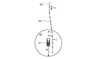
例えば、図6に示すように先ず走行時刻tが初期値である0(即ち現在時刻)の場合には、車両の現在位置を軌道生成開始点51として、目標走行軌道50上に制御目標地点52が設定される。そして、軌道生成開始点51から制御目標地点52までの走行軌道53が生成される。更に、生成された走行軌道53に沿って車両が100msec走行したと仮定して現在時刻から100msec後の車両位置54が予測される。
次に、図7に示すように100msec後の車両位置54(即ち走行時刻tが100msecの場合において予測される車両の位置)を新たな軌道生成開始点51として、目標走行軌道50上に新たな制御目標地点52が設定される。そして、同様に軌道生成開始点51から制御目標地点52までの走行軌道53が生成される。更に、生成された走行軌道53に沿って車両が100msec走行したと仮定して現在時刻から200msec後の車両の位置55が予測される。
以下同様にして現在時刻から300msec後の車両の位置、400msec後の車両の位置、・・・・が車両の走行距離が停止距離以上と判定されるまで予測される。
For example, as shown in FIG. 6, when the travel time t is 0 (that is, the current time) which is an initial value, the current position of the vehicle is set as the trajectory generation start
Next, as shown in FIG. 7, the
Similarly, the position of the vehicle after 300 msec from the current time, the position of the vehicle after 400 msec,... Are predicted until the travel distance of the vehicle is determined to be equal to or greater than the stop distance.
そして、前記S18で算出された走行距離が前記S11で算出された停止距離以上であると判定された場合(S19:YES)には、S20へと移行する。S20でCPU41は、前記S14〜S18の処理を繰り返し実行することによって特定された各走行時刻t(t=0、100msec、200msec、300msec、・・・)における車両の位置を繋いだ軌道を制御軌道として生成する。尚、各走行時刻tにおける車両の位置を繋ぐ際には、各位置における車両の方位についても考慮する。各位置における車両の方位は前記S17で特定されている。また、旋回回数が少なく旋回半径ができる限り大きくなるように繋ぐのが望ましい。
And when it determines with the travel distance calculated by said S18 being more than the stop distance calculated by said S11 (S19: YES), it transfers to S20. In S20, the
例えば、図8に示すように目標走行軌道50に対して現在時刻(走行時刻t=0)の車両の位置51、現在時刻から100msec後(走行時刻t=100msec)の車両の位置54、200msec後(走行時刻t=200msec)の車両の位置55、300msec後(走行時刻t=300msec)の車両の位置56が特定されている場合には、各車両の位置51、54、55、56を繋いだ軌道を制御軌道60として生成する。
For example, as shown in FIG. 8, the
尚、前記S15で生成された走行軌道53の一部を繋げて制御軌道60を生成しても良い。即ち、図6に示す軌道生成開始点51から予測車両位置54までの走行軌道53と、図7に示す軌道生成開始点51から予測車両位置55までの走行軌道53とを繋げた軌道を制御軌道60として生成しても良い。
Note that the
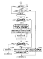
次に、前記S14において実行される制御目標地点設定処理のサブ処理について図9及び図10に基づき説明する。図9及び図10は制御目標地点設定処理のサブ処理プログラムのフローチャートである。 Next, the sub-process of the control target point setting process executed in S14 will be described with reference to FIGS. 9 and 10 are flowcharts of a sub-processing program of the control target point setting process.
先ず、S21においてCPU41は、前記S3で設定された目標走行軌道上に所定間隔で仮目標位置を設定する。仮目標位置は制御目標地点の候補となる点である。仮目標位置を狭い間隔でより多数設定すればより最適な制御目標地点を選択することが可能であるが、一方でCPU41の処理負担は増加する。仮目標位置を設定する間隔は例えば1mとする。尚、目標走行軌道の全軌道に対して仮目標位置を設定しても良いし、車両の現在位置周辺の目標走行軌道のみに対して仮目標位置を設定しても良い。
First, in S21, the
次に、S22においてCPU41は、車両において現在実施されている自動運転支援の支援内容を取得する。尚、本実施形態では、上述したように右左折、合流、分岐等の特殊な状況下を除いて基本的に『車線維持走行支援』と『車線変更支援』のいずれかの自動運転支援を行う。
Next, in S <b> 22, the
また、S23においてCPU41は、RAM42に格納された直近の除外範囲距離を示すパラメータXt−1を読み出す。尚、直近の除外範囲距離を示すパラメータXt−1は、前記S13又は後述のS31で設定される。
In S <b> 23, the
続いて、S24においてCPU41は、前記S22の取得結果に基づいて車両において現在実施されている自動運転支援の支援内容が、『車線維持走行支援』と『車線変更支援』のいずれかであるか判定する。
Subsequently, in S24, the
そして、車両において現在実施されている自動運転支援の支援内容が『車線維持走行支援』であると判定された場合(S24:YES)には、S25へと移行する。一方、車両において現在実施されている自動運転支援の支援内容が『車線変更支援』であると判定された場合(S24:NO)には、S28へと移行する。 And when it determines with the assistance content of the automatic driving assistance currently implemented in the vehicle being "lane maintenance driving assistance" (S24: YES), it transfers to S25. On the other hand, when it is determined that the support content of the automatic driving support currently being implemented in the vehicle is “lane change support” (S24: NO), the process proceeds to S28.
S25においてCPU41は、前記S23で取得された直近の除外範囲距離Xt−1が5mより大きいか否かを判定する。尚、直近の除外範囲距離Xt−1は、今回の制御軌道を生成するに際して過去に実施された制御目標地点設定処理(S14)の内、特に直近に実施された制御目標地点設定処理(S14)で設定された除外範囲距離を示す値である。但し、走行時刻tが0の場合、即ち今回の制御軌道を生成するに際して最初に制御目標地点設定処理が実行された場合には、前回の制御軌道を生成する際に設定された除外範囲距離を示す値となる(S7、S13)。また、除外範囲距離は、後述のように仮目標位置から制御目標地点を選択するに際して、制御目標地点の初期段階の選択対象から除外する範囲(以下、除外範囲という)の大きさを定義する距離であり、具体的には軌道生成開始点を中心とした除外範囲距離内の範囲を除外範囲とする。
In S25, the
そして、直近の除外範囲距離Xt−1が5mより大きいと判定された場合(S25:YES)には、S27へと移行する。それに対して、直近の除外範囲距離Xt−1が5m以下であると判定された場合(S25:NO)には、S26へと移行する。 If it is determined that the latest exclusion range distance Xt-1 is greater than 5 m (S25: YES), the process proceeds to S27. On the other hand, when it is determined that the latest exclusion range distance Xt-1 is 5 m or less (S25: NO), the process proceeds to S26.
S26においてCPU41は、今回の除外範囲距離Xtを5mに設定する。その後、S31へと移行する。
In S26, the
S27においてCPU41は、今回の除外範囲距離Xtを『Xt−1−1m』と『5m』の内、大きい方の値とする。その後、S31へと移行する。
In
一方、S28においてCPU41は、前記S23で取得された直近の除外範囲距離Xt−1が10mより大きいか否かを判定する。
On the other hand, in S28, the
そして、直近の除外範囲距離Xt−1が10mより大きいと判定された場合(S28:YES)には、S30へと移行する。それに対して、直近の除外範囲距離Xt−1が10m以下であると判定された場合(S28:NO)には、S29へと移行する。 If it is determined that the latest exclusion range distance Xt-1 is greater than 10 m (S28: YES), the process proceeds to S30. On the other hand, when it is determined that the latest exclusion range distance Xt-1 is 10 m or less (S28: NO), the process proceeds to S29.
S29においてCPU41は、今回の除外範囲距離Xtを20mに設定する。その後、S31へと移行する。
In S29, the
一方、S30においてCPU41は、今回の除外範囲距離Xtを『Xt−1−1m』と『10m』の内、大きい方の値とする。その後、S31へと移行する。
On the other hand,
上記S26、S27、S29、S30の処理を実行することによって、複数の仮目標位置から制御目標地点を選択するに際して、制御目標地点の初期段階の選択対象から除外する範囲である除外範囲が設定される。尚、除外範囲を広く設定すると、車両の現在位置が目標走行軌道から外れていた場合には軌道の修正に時間がかかるが、より緩やかで車両方位の変化の少ない旋回を描く制御軌道となる。一方で、除外範囲を狭く設定すると、車両の現在位置が目標走行軌道から外れていた場合に短時間で軌道の修正が可能となるが、急な旋回を描く制御軌道になり易い。 By executing the processes of S26, S27, S29, and S30, when selecting a control target point from a plurality of temporary target positions, an exclusion range that is a range to be excluded from selection targets at the initial stage of the control target point is set. The If the exclusion range is set wide, it takes a long time to correct the trajectory when the current position of the vehicle deviates from the target travel trajectory, but it becomes a control trajectory that draws a more gentle turn with little change in the vehicle direction. On the other hand, if the exclusion range is set narrow, the trajectory can be corrected in a short time when the current position of the vehicle deviates from the target travel trajectory, but it tends to be a control trajectory that draws a sharp turn.
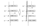
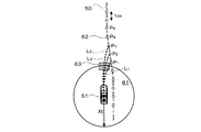
ここで、車両において『車線維持走行支援』が行われている場合には、図11に示すように基本的に狭い除外範囲61(例えば軌道生成開始点51を中心とした5m内)が設定される(S26)。車両において『車線維持走行支援』が行われている場合には、比較的機敏に走行位置を修正できた方が、車線中央からずれることが少なくなり、ふらつきを抑えることができる。従って、『車線維持走行支援』が行われている場合においては、制御目標地点を比較的近い位置に設定した方が優位になることが多い。従って、基本的に狭い除外範囲61を設定する。
Here, when “lane keeping driving support” is performed in the vehicle, a basically narrow exclusion range 61 (for example, within 5 m centering on the trajectory generation start point 51) is set as shown in FIG. (S26). When “lane keeping driving support” is being performed on the vehicle, it is less likely to deviate from the center of the lane if the driving position can be corrected relatively quickly, and fluctuations can be suppressed. Therefore, when “lane keeping driving support” is being performed, it is often advantageous to set the control target point relatively close. Therefore, basically a
但し、車両において『車線維持走行支援』が行われている場合であっても、前回の走行時刻tにおける処理で除外範囲が広く(例えば除外範囲距離>5m)設定されていた場合については、狭い除外範囲に一度に切り替えるのではなく、複数段階で徐々に除外範囲を狭く切り替える(S27)。具体的には、走行時刻tが100ms加算される毎に除外範囲距離を1mずつ短くする(但し最小は5mとする)。ここで、制御目標地点を軌道生成開始点51の遠方から近傍へと急に変化させると、生成される制御軌道の旋回半径が急に小さく(横加速度が急に大きく)なる虞がある。本実施形態では、除外範囲を狭くする場合には段階的に狭くすることによって上記問題を解消することが可能となる。尚、逆に除外範囲を広くする場合においては上記問題が生じないので複数段階で広げるのではなく1段階で広げても良い。
However, even when “lane keeping driving support” is performed in the vehicle, the case where the exclusion range is set wide (for example, the exclusion range distance> 5 m) in the process at the previous traveling time t is narrow. Instead of switching to the exclusion range at once, the exclusion range is gradually narrowed in multiple steps (S27). Specifically, every time the travel time t is added by 100 ms, the exclusion range distance is shortened by 1 m (however, the minimum is 5 m). Here, if the control target point is suddenly changed from far away to the vicinity of the trajectory generation start
一方、車両において『車線変更支援』が行われている場合には、初期段階では図12に示すように基本的に広い除外範囲(例えば軌道生成開始点51を中心とした20m内)が設定される(S29)。その後、『車線変更支援』を継続するにあたって走行時刻tが100ms加算される毎に除外範囲距離を1mずつ短くする(S30、但し最小は10mとする)。ここで、車両において『車線変更支援』が行われている場合には、急いで車線変更する必要がある場合を除いて、比較的緩やかに走行位置を変化させ、車線に対して車体の角度をつけすぎずに移動することが好ましい。従って、『車線変更支援』が行われている場合においては、制御目標地点を比較的遠い位置に設定した方が優位になることが多い。そこで、『車線維持走行支援』よりも広い除外範囲61を設定する。特に、車線変更の制御開始時は除外範囲を広くすることによって、よりスムーズな車線変更制御が可能となる。尚、除外範囲を初期段階から狭くする場合には、『車線維持走行支援』が行われている場合と同様に段階的に狭くすることによって生成される制御軌道の旋回半径が急に小さく(横加速度が急に大きく)ことを防止する。
On the other hand, when “lane change support” is being performed on the vehicle, a basically wide exclusion range (for example, within 20 m centering on the trajectory generation start point 51) is set at the initial stage as shown in FIG. (S29). Thereafter, every time the travel time t is added by 100 ms for continuing the “lane change support”, the exclusion range distance is shortened by 1 m (S30, where the minimum is 10 m). Here, when “lane change support” is performed on the vehicle, the travel position is changed relatively slowly, and the angle of the vehicle body with respect to the lane is changed, unless it is necessary to change the lane quickly. It is preferable to move without wearing too much. Therefore, when “lane change support” is being performed, it is often more advantageous to set the control target point at a relatively distant position. Therefore, an
ここで、図13は走行時刻tの変位に伴う除外範囲の具体的な設定例を示した図である。尚、図13では、走行時刻tが0(現在時刻)〜100msの間において自動運転支援として『車線維持走行支援』が実施され、走行時刻tが200ms〜1400msの間において『車線変更支援』が実施され、走行時刻tが1500ms以降において再び『車線維持走行支援』が実施される場合を例に挙げて説明する。 Here, FIG. 13 is a diagram showing a specific setting example of the exclusion range accompanying the displacement of the travel time t. In FIG. 13, “lane keeping travel support” is implemented as automatic driving support when the travel time t is 0 (current time) to 100 ms, and “lane change support” is performed when the travel time t is 200 ms to 1400 ms. A case will be described as an example where the “lane keeping travel support” is performed again after the travel time t is 1500 ms.
図13に示すように先ず自動運転支援の内容が『車線維持走行支援』が行われている走行時刻tが0(現在時刻)〜100msの間においては、除外範囲距離が5mとなり、軌道生成開始点51を中心とした5m内が除外範囲として設定される(S26)。その後に、走行時刻tが200msのタイミングで自動運転支援の内容が『車線維持走行支援』から『車線変更制御』へと切り替わると、除外範囲距離は5mから20mへと1段階で切り替わり、軌道生成開始点51を中心とした20m内が除外範囲として設定される(S29)。そして、走行時刻tが200ms〜1400msの間においては『車線変更支援』が継続して実施されるので、除外範囲距離が20mから徐々に短くなり、除外範囲も徐々に狭くなる(S30)。但し、下限は除外範囲距離が10mであるので、除外範囲距離が10mに到達した後はそれ以上短くすることなく維持される。また、走行時刻tが1500msのタイミングで自動運転支援の内容が『車線変更制御』から『車線維持走行支援』へと切り替わると、その後は除外範囲距離が10mから5mへと複数段階で段階的に切り替わる。具体的には、走行時刻tが100ms加算される毎に除外範囲距離を1mずつ短くする。それに伴って除外範囲も徐々に狭くなる(S27)。そして、除外範囲距離が5mに到達した後はそれ以上短くすることなく維持される。
As shown in FIG. 13, first, when the driving time t when the content of the automatic driving support is “lane keeping driving support” is 0 (current time) to 100 ms, the excluded range distance is 5 m, and the track generation starts. An area within 5 m centering on the
尚、本実施形態では以下に説明するように前記S21で設定された仮目標位置の内、先ず前記S26、S27、S29、S30で設定された除外範囲の外にある仮目標位置を候補として制御目標地点を設定する。但し、車両の走行する軌道周辺に障害物があって、除外範囲の外で障害物を回避する制御目標地点が設定できない場合には、除外範囲内にある仮目標位置についても候補として制御目標地点を設定する。 In the present embodiment, as will be described below, the temporary target positions that are outside the exclusion range set in S26, S27, S29, and S30 among the temporary target positions set in S21 are controlled as candidates. Set the target point. However, if there is an obstacle around the track where the vehicle is traveling and a control target point that avoids the obstacle cannot be set outside the exclusion range, the temporary target position within the exclusion range is also a candidate for the control target point. Set.
その後、S31においてCPU41は、RAM42に格納された直近の除外範囲距離を示すパラメータXt−1を読み出し、前記S26、S27、S29、S30のいずれかで設定された今回の除外範囲距離Xtを代入(更新)する。
Thereafter, in
以下のS32〜S35の処理は、前記S21で設定された仮目標位置の内、制御目標地点の候補となる仮目標位置を対象に、軌道生成開始点から近い順に仮目標位置毎に実行する。尚、S32〜S35の処理において制御目標地点の候補となる仮目標位置は、前記S26、S27、S29、S30で設定された除外範囲の外にあって、且つ軌道生成開始点51から所定距離以内(例えば300m以内)にある仮目標位置とする。例えば、図14に示す例では、目標走行軌道50に対して仮目標位置62が所定間隔(例えば1m間隔)で設定されているが、軌道生成開始点51から今回の除外範囲距離Xt以内の除外範囲61外にある仮目標位置62を制御目標地点の候補とする。そして、除外範囲61外にある仮目標位置62の内、最も軌道生成開始点51に近い地点P1を対象に先ずS32〜S35の処理が行われる。その後、P2、P3、・・・の順にS32〜S35の処理が行われる。
The following processes of S32 to S35 are executed for each temporary target position in order from the trajectory generation start point to the temporary target position that is a candidate for the control target point among the temporary target positions set in S21. Note that the temporary target position that is a candidate for the control target point in the processing of S32 to S35 is outside the exclusion range set in S26, S27, S29, and S30 and within a predetermined distance from the trajectory generation start
先ず、S32においてCPU41は、軌道生成開始点から処理対象の仮目標位置へと到達する軌道(以下、到達軌道という)を生成する。具体的には軌道生成開始点から処理対象の仮目標位置までを、最も旋回半径が大きくなるように繋いだ軌道を到達軌道として生成する。更に、前記S32においてCPU41は、生成した到達軌道に含まれる旋回の内、最小の旋回半径を算出する。即ち、前記S32では軌道生成開始点から処理対象の仮目標位置へと到達するのに必要な最小の旋回半径が算出される。尚、軌道生成開始点は現時点の走行時刻t(現在時刻からt時間後)において予測される車両の位置であり、前記S17で特定される。特に走行時刻tが初期値である0の場合は、軌道生成開始点は車両の現在位置となる。
First, in S32, the
次に、S33においてCPU41は、後述の障害物判定処理(図18)を実行する。ここで、障害物判定処理は、軌道生成開始点から処理対象の仮目標位置へと到達する到達軌道が障害物を回避できる軌道であるか否かを判定する処理である。尚、障害物は自動運転支援に影響する対象物(要因)であり、例えば周辺を走行する他車両、路上に停車する駐車車両、工事区間、渋滞車両等が該当する。
Next, in S33, the
続いて、S34においてCPU41は、前記S33の障害物判定処理の結果に基づいて、軌道生成開始点から処理対象の仮目標位置へと到達する到達軌道が障害物を回避できる軌道であるか否かを判定する。
Subsequently, in S34, based on the result of the obstacle determination processing in S33, the
そして、軌道生成開始点から処理対象の仮目標位置へと到達する到達軌道が障害物を回避できる軌道であると判定された場合(S34:YES)には、S35へと移行する。一方、軌道生成開始点から処理対象の仮目標位置へと到達する到達軌道が障害物を回避できない軌道であると判定された場合(S34:NO)には、処理対象となる仮目標位置を次に軌道生成開始点に近い他の仮目標位置へと切り替えた後にS32以降の処理を再度実行する。 When it is determined that the arrival trajectory that reaches the temporary target position to be processed from the trajectory generation start point is a trajectory that can avoid the obstacle (S34: YES), the process proceeds to S35. On the other hand, when it is determined that the arrival trajectory that reaches the temporary target position to be processed from the trajectory generation start point is a trajectory that cannot avoid the obstacle (S34: NO), the temporary target position to be processed is set to the next. After switching to another temporary target position close to the trajectory generation start point, the processes after S32 are executed again.
S35においてCPU41は、前記S32で算出された旋回半径が閾値以上であるか否かを判定する。尚、閾値は、走行する車両の自動運転支援に係る走行制御を適切に行うことができ、且つ走行中の車両の乗員に負担が生じない条件を満たす最小の旋回半径とする。例えば、横加速度が0.2G以下であることを条件とすると、閾値は以下の式(1)により算出される。
閾値=車速2/(0.2G×9.80665)・・・・(1)
In S35, the
Threshold = vehicle speed 2 /(0.2G×9.80665) (1)
そして、前記S32で算出された旋回半径が閾値以上であると判定された場合(S35:YES)には、S36へと移行する。そして、S36においてCPU41は、処理対象の仮目標位置を制御目標地点に設定する。即ち、除外範囲の外で軌道生成開始点から近い位置にある仮目標位置を優先して制御目標位置に設定することとなる。
And when it determines with the turning radius calculated by said S32 being more than a threshold value (S35: YES), it transfers to S36. In S36, the
一方、前記S32で算出された旋回半径が閾値未満であると判定された場合(S35:NO)には、処理対象となる仮目標位置を次に軌道生成開始点に近い他の仮目標位置へと切り替えた後にS32の処理を再度実行する。そして、処理対象となる全ての仮目標位置を対象として前記S32〜S35の処理を実行した結果、障害物を回避でき且つ旋回半径が閾値以上となる仮目標位置が存在しない場合には、S37へと移行する。 On the other hand, if it is determined that the turning radius calculated in S32 is less than the threshold value (S35: NO), the temporary target position to be processed is next moved to another temporary target position close to the trajectory generation start point. After switching, the process of S32 is executed again. Then, as a result of executing the processes of S32 to S35 for all the temporary target positions to be processed, if there is no temporary target position where an obstacle can be avoided and the turning radius is equal to or greater than the threshold value, the process proceeds to S37. And migrate.
S37においてCPU41は、前記S33の障害物判定処理の結果に基づいて、軌道生成開始点から前記S32〜S35において処理対象となった全ての仮目標位置へと到達する各到達軌道がいずれも障害物を回避できない軌道であったか否かを判定する。
In S37, based on the result of the obstacle determination process in S33, the
そして、軌道生成開始点から前記S32〜S35において処理対象となった全ての仮目標位置へと到達する各到達軌道がいずれも障害物を回避できない軌道であったと判定された場合(S37:YES)には、S39へと移行する。一方、障害物を回避できる仮目標位置があったと判定された場合(S37:NO)には、S38へと移行する。 Then, when it is determined that each of the arrival trajectories that reach all the temporary target positions to be processed in S32 to S35 from the trajectory generation start point is a trajectory that cannot avoid the obstacle (S37: YES). The process proceeds to S39. On the other hand, when it is determined that there is a temporary target position that can avoid the obstacle (S37: NO), the process proceeds to S38.
S38においてCPU41は、前記S32〜S35において処理対象となった仮目標位置(除外範囲の外、且つ軌道生成開始点51から所定距離以内(例えば300m以内)にある仮目標位置)であって且つ障害物を回避できる仮目標位置の内、前記S32で算出された旋回半径の最も大きい仮目標位置を制御目標地点に設定する。尚、対象が複数ある場合には該当する複数の仮目標位置の内、最も軌道生成開始点に近い仮目標位置を制御目標地点に設定する。
In S38, the
一方、S39及びS40の処理は、前記S21で設定された仮目標位置の内、制御目標地点の候補となる仮目標位置を対象に、軌道生成開始点から遠い順に仮目標位置毎に実行する。尚、S39及びS40の処理において制御目標地点の候補となる仮目標位置は、前記S26、S27、S29、S30で設定された除外範囲内にある仮目標位置とする。例えば、図15に示す例では、目標走行軌道50に対して仮目標位置62が所定間隔(例えば1m間隔)で設定されているが、軌道生成開始点51から今回の除外範囲距離Xt以内の除外範囲61内にある仮目標位置62について制御目標地点の候補とする。そして、除外範囲61内にある仮目標位置62の内、最も軌道生成開始点51に遠い地点P11を対象に先ずS39及びS40の処理が行われる。その後、P12、P13、・・・の順にS39及びS40の処理が行われる。但し、軌道生成開始点51より車両の進行方向に対して後方にある仮目標位置62については処理対象から除外する。
On the other hand, the processes of S39 and S40 are executed for each temporary target position in order of increasing distance from the trajectory generation start point, with respect to the temporary target position that is a candidate for the control target point among the temporary target positions set in S21. Note that the temporary target position that is a candidate for the control target point in the processing of S39 and S40 is the temporary target position that is within the exclusion range set in S26, S27, S29, and S30. For example, in the example shown in FIG. 15, although
先ず、S39においてCPU41は、前記S32と同様に軌道生成開始点から処理対象の仮目標位置へと到達する到達軌道を生成する。更に、前記S39においてCPU41は、生成した到達軌道に含まれる旋回の内、最小の旋回半径を算出する。即ち、前記S32では軌道生成開始点から処理対象の仮目標位置へと到達するのに必要な最小の旋回半径が算出される。
First, in S39, the
次に、S40においてCPU41は、後述の障害物判定処理(図18)を実行する。ここで、障害物判定処理は、軌道生成開始点から処理対象の仮目標位置へと到達する到達軌道が障害物を回避できる軌道であるか否かを判定する処理である。
Next, in S40, the
続いて、S41においてCPU41は、前記S40の障害物判定処理の結果に基づいて、軌道生成開始点から前記S39及びS40において処理対象となった全ての仮目標位置へと到達する各到達軌道がいずれも障害物を回避できない軌道であったか否かを判定する。
Subsequently, in S41, based on the result of the obstacle determination process in S40, the
そして、軌道生成開始点から前記S39及びS40において処理対象となった全ての仮目標位置へと到達する各到達軌道がいずれも障害物を回避できない軌道であったと判定された場合(S41:YES)には、S42へと移行する。一方、障害物を回避できる仮目標位置があったと判定された場合(S41:NO)には、S38へと移行する。 Then, when it is determined that each of the reaching trajectories that reach all the temporary target positions to be processed in S39 and S40 from the trajectory generation start point is a trajectory that cannot avoid the obstacle (S41: YES). The process proceeds to S42. On the other hand, when it is determined that there is a temporary target position that can avoid the obstacle (S41: NO), the process proceeds to S38.
S38においてCPU41は、前記S39及びS40において処理対象となった仮目標位置(除外範囲内にある仮目標位置)であって且つ障害物を回避できる仮目標位置の内、前記S39で算出された旋回半径の最も大きい仮目標位置を制御目標地点に設定する。尚、対象が複数ある場合には該当する複数の仮目標位置の内、最も軌道生成開始点から遠い仮目標位置を制御目標地点に設定する。
In S38, the
一方、S42においてCPU41は、障害物を回避するための車両の制御軌道を設定することが困難であると判定する。その結果、CPU41は障害物を回避する為の緊急の回避制御の実行指示を、CANを介して車両制御ECU20へと送信する。尚、緊急の回避制御としては例えばAEB(Autonomous Emergency. Braking)がある。
On the other hand, in S42, the
上記S32〜S42の処理を行った結果、図16に示すように目標走行軌道50に対して仮目標位置62が所定間隔で設定されている場合には、先ず除外範囲61外にある仮目標位置62の内、最も軌道生成開始点51に近い地点P1を対象に地点P1に到達する到達軌道L1が生成され、該到達軌道L1が障害物63を回避でき且つ旋回半径が閾値以上か否か判定される。そして、到達軌道L1が障害物63を回避できない或いは旋回半径が閾値未満である場合には、次に軌道生成開始点51に近い地点P2を対象に地点P2に到達する到達軌道L2が生成され、該到達軌道L2が障害物63を回避でき且つ旋回半径が閾値以上か否か判定される。更に、到達軌道L2が障害物63を回避できない或いは旋回半径が閾値未満である場合には、次に軌道生成開始点51に近い地点P3を対象に地点P3に到達する到達軌道L3が生成され、該到達軌道L3が障害物63を回避でき且つ旋回半径が閾値以上か否か判定される。以下同様にして、軌道生成開始点51に近い順に各地点へ到達する到達軌道が障害物63を回避でき且つ旋回半径が閾値以上であるか否か判定される。そして、障害物63を回避でき且つ旋回半径が閾値以上であって、軌道生成開始点51に最も近い仮目標位置62を制御目標地点に設定する。一方、旋回半径が閾値以上となる仮目標位置62が存在しない場合には、障害物63を回避できる仮目標位置62の内、最も旋回半径の大きい仮目標位置62を制御目標地点に設定する。
As a result of performing the processes of S32 to S42, when the
更に、除外範囲61外に障害物63を回避できる仮目標位置62が存在しない場合には、図17に示すように除外範囲61内にある仮目標位置62についても制御目標地点の候補とする。先ず、除外範囲61内にある仮目標位置62の内、最も軌道生成開始点51から遠い地点P11を対象に地点P11に到達する到達軌道L11が生成され、該到達軌道L11が障害物63を回避できるか否か判定される。以下同様に除外範囲61内にある他の仮目標位置62である地点P12、P13についても対象に到達軌道L12、L13が生成され、該到達軌道L12、L13が障害物63を回避できるか否か判定される。そして、障害物63を回避できる仮目標位置62の内、最も旋回半径の大きい仮目標位置62を制御目標地点に設定する。
Furthermore, when there is no
次に、前記S33及びS40において実行される障害物判定処理のサブ処理について図18に基づき説明する。図18は障害物判定処理のサブ処理プログラムのフローチャートである。 Next, the sub-process of the obstacle determination process executed in S33 and S40 will be described with reference to FIG. FIG. 18 is a flowchart of a sub-processing program for obstacle determination processing.
先ず、S51においてCPU41は、軌道生成開始点から処理対象の仮目標位置へと到達する到達軌道を読み出す。尚、軌道生成開始点から処理対象の仮目標位置へと到達する到達軌道は、前記S32又はS39で生成される。
First, in S51, the
次に、S52においてCPU41は、パラメータである判定時刻Tに初期値として0(0は現時点の走行時刻tに相当する)を設定する。尚、判定時刻TはRAM42等に記憶される。
Next, in S52, the
その後、S53においてCPU41は、RAM42から判定時刻Tを読み出し、10msec加算する。
Thereafter, in S53, the
次に、S54においてCPU41は、車両が前記S51で読み出した到達軌道の軌道生成開始点から到達軌道に沿って現在の車両の車速で走行したと仮定して、現時点の判定時刻T(走行時刻tからT時間後)における車両の位置と方位を予測する。具体的には、軌道生成開始点から前記S51で読み出した到達軌道に沿って現在の車両の車速で10ms走行した場合の走行距離だけ離れた地点を、現時点の判定時刻T(走行時刻tからT時間後)における車両の位置とする。また、予測された車両の位置における到達軌道の接線方向が現時点の判定時刻T(走行時刻tからT時間後)における車両の方位となる。
Next, in S54, the
続いて、S55においてCPU41は、前記S54で予測された車両の位置及び方位と車両情報(車両の全長、全幅)とに基づいて、車両が前記S51で読み出した到達軌道の軌道生成開始点から到達軌道に沿って現在の車両の車速で走行したと仮定して、現時点の判定時刻T(走行時刻tからT時間後)における車両の占有領域を算出する。例えば図19に示すような軌道生成開始点51から処理対象の仮目標位置62までの到達軌道65が生成されている場合には、現時点の判定時刻Tにおいて予測される車両の位置66を含み、予測される方位を進行方向とした車両の形状に対応する領域67が判定時刻Tにおける車両の占有領域となる。尚、前記S55では、誤差を考慮する為に一旦算出された車両の占有領域を所定範囲(例えば前後左右25cmずつ)広げた領域を最終的な車両の占有領域として算出する。
Subsequently, in S55, the
一方、S56においてCPU41は、障害物情報DB32に記憶された障害物情報に基づいて、現時点の判定時刻T(走行時刻tからT時間後)における障害物の占有領域を算出する。尚、障害物は、車両において後述のように実施される自動運転支援に影響する対象物(要因)であり、例えば周辺を走行する他車両、路上に停車する駐車車両、工事区間、渋滞車両等が該当する。また、障害物情報DB32には障害物の形状や、障害物が移動体である場合には移動方向や移動速度を特定する情報を含んでいる。従って、障害物が特に移動体である場合には、検出時点の障害物の占有領域に対して移動方向及び移動速度を考慮して判定時刻Tにおける障害物の占有領域を算出する。一方、障害物が移動体でない場合には、検出時点の障害物の占有領域が判定時刻Tにおける障害物の占有領域にも相当する。尚、車両の進行方向周辺に障害物が存在しない(障害物情報が無い)場合には、障害物の占有領域は存在しないと特定する。また、車両の進行方向周辺に障害物が存在しない(障害物情報が無い)場合には、S51〜S59の処理は省略しても良い。
On the other hand, in S56, the
その後、S57においてCPU41は、前記S55で算出された現時点の判定時刻T(走行時刻tからT時間後)における車両の占有領域と、前記S56で算出された現時点の判定時刻T(走行時刻tからT時間後)における障害物の占有領域とを比較し、両者の占有領域の少なくとも一部が重複するか否かを判定する。尚、重複しなくても所定距離(例えば30cm)以内まで接近する場合には重複するとみなしても良い。
Thereafter, in S57, the
そして、両者の占有領域の少なくとも一部が重複すると判定された場合(S57:YES)には、S58へと移行する。それに対して、両者の占有領域が重複しないと判定された場合(S57:NO)には、S59へと移行する。 And when it determines with at least one part of both occupation area | regions overlapping (S57: YES), it transfers to S58. On the other hand, if it is determined that the occupied areas of both do not overlap (S57: NO), the process proceeds to S59.
S58においてCPU41は、軌道生成開始点から処理対象の仮目標位置へと到達する到達軌道が障害物を回避できない軌道であると判定する。尚、判定結果はフラッシュメモリ44等に記憶される。その後、当該障害物判定処理のサブ処理を終了する。
In S <b> 58, the
一方、S59においてCPU41は、RAM42から現時点の判定時刻Tを読み出し、判定時刻Tが100msec以上であるか否かを判定する。
On the other hand, in S59, the
そして、判定時刻Tが100msec以上であると判定された場合(S59:YES)、即ち判定時刻Tが10msec〜100msecまでの間において車両の占有領域と障害物の占有領域が重複しないと判定された場合には、S60へと移行する。それに対して、判定時刻Tが100msec未満であると判定された場合(S59:NO)には、S53へと戻る。その後、判定時刻Tが10msec加算され、新たな判定時刻Tにおける車両と障害物の占有領域の比較(S54〜S57)が行われる。 If it is determined that the determination time T is 100 msec or more (S59: YES), that is, it is determined that the vehicle occupation area and the obstacle occupation area do not overlap during the determination time T from 10 msec to 100 msec. In the case, the process proceeds to S60. On the other hand, when it is determined that the determination time T is less than 100 msec (S59: NO), the process returns to S53. Thereafter, the determination time T is added by 10 msec, and the vehicle and the occupied area of the obstacle at the new determination time T are compared (S54 to S57).
S60においてCPU41は、軌道生成開始点から処理対象の仮目標位置へと到達する到達軌道が障害物を回避できる軌道であると判定する。尚、判定結果はフラッシュメモリ44等に記憶される。その後、当該障害物判定処理のサブ処理を終了する。
In S60, the
以上詳細に説明した通り、本実施形態に係るナビゲーション装置1及びナビゲーション装置1で実行されるコンピュータプログラムでは、車両が走行する道路に対して目標とする走行軌道である目標走行軌道50を設定し(S3)、目標走行軌道50上であって障害物を回避できる進行方向前方の位置に、制御目標地点52を設定し(S14)、軌道生成開始点51から制御目標地点52へと走行する軌道を用いて、車両に走行させる制御軌道60を生成する(S20)ので、自動運転支援による車両の走行が行われている場合において、障害物を回避する制御軌道を生成することが可能となる。従って、障害物が存在した場合であっても自動運転支援による走行を車両の停止制御を行うことなしにできる限り継続して行うことが可能である。
As described in detail above, the
尚、本発明は前記実施形態に限定されるものではなく、本発明の要旨を逸脱しない範囲内で種々の改良、変形が可能であることは勿論である。
例えば、本実施形態では、到達軌道が障害物を回避できる軌道であるか否かの判定(S57)を、判定時刻T毎の車両と障害物の占有領域を比較することにより行っているが、他の方法を用いても良い。例えば、障害物の移動軌道を算出し、到達軌道と障害物の移動軌道が所定距離以内に接近するか否かを判定し、所定距離以内に接近しない場合に到達軌道が障害物を回避できる軌道であると判定しても良い。
Note that the present invention is not limited to the above-described embodiment, and various improvements and modifications can be made without departing from the scope of the present invention.
For example, in the present embodiment, the determination as to whether or not the arrival trajectory is a trajectory that can avoid an obstacle (S57) is performed by comparing the vehicle and the occupied area of the obstacle at each determination time T. Other methods may be used. For example, calculate the obstacle trajectory, determine whether the arrival trajectory and the obstacle trajectory approach within a predetermined distance, and if the arrival trajectory does not approach within a predetermined distance, the trajectory that can avoid the obstacle It may be determined that
また、本実施形態では、車両に対して行われる自動運転支援として特に『車線維持走行支援』と『車線変更支援』を例に挙げて説明しているが、それ以外の自動運転支援が行われる場合においても実施可能である。例えば、前方車両との車間距離を一定距離(例えば10m)に保つ制御、一定速度(例えば制限速度の80%)で走行する制御を行う自動運転支援がある。それらの支援内容に応じて除外範囲距離を適宜設定することにより、自動運転支援の支援内容に応じた形状を有する制御軌道を生成することが可能となる。 Further, in the present embodiment, “lane maintenance support” and “lane change support” are described as examples of the automatic driving support performed on the vehicle, but other automatic driving support is performed. In some cases, it can be implemented. For example, there are automatic driving support that performs control for keeping the distance between the vehicle ahead and a vehicle at a constant distance (for example, 10 m) and control for traveling at a constant speed (for example, 80% of the speed limit). By appropriately setting the exclusion range distance according to the support content, it is possible to generate a control trajectory having a shape according to the support content of the automatic driving support.
また、本実施形態では、『車線維持走行支援』が行われている場合には除外範囲距離を基本的に5mに設定し、『車線変更支援』が行われている場合には除外範囲距離を基本的に10m〜20mに設定しているが、その距離は適宜変更可能である。例えば、障害物が近くにある場合には除外範囲距離をより短い距離(例えば2.5m)に設定しても良い。 In the present embodiment, the exclusion range distance is basically set to 5 m when “lane keeping driving support” is performed, and the exclusion range distance is set when “lane change support” is performed. The distance is basically set to 10 to 20 m, but the distance can be changed as appropriate. For example, when an obstacle is nearby, the exclusion range distance may be set to a shorter distance (for example, 2.5 m).
また、本実施形態では、『車線変更支援』が継続して実施される場合において除外範囲距離を時間経過に伴って徐々に短く設定しているが、『車線維持走行支援』が継続して実施される場合においても同様に除外範囲距離を時間経過に伴って徐々に短く設定しても良い。更に、『車線変更支援』が継続して実施された場合であっても、除外範囲距離を短くすることなく固定の距離としても良い。 In this embodiment, when “lane change support” is continuously implemented, the exclusion range distance is gradually shortened with time, but “lane maintenance travel support” is continuously implemented. Similarly, the exclusion range distance may be set to be gradually shortened with time. Furthermore, even if “lane change support” is continuously performed, the exclusion range distance may be fixed without shortening.
また、本実施形態では、車両の操作のうち、車両の挙動に関する操作である、アクセル操作、ブレーキ操作及びハンドル操作の全てを車両制御ECU20が制御することをユーザの運転操作によらずに自動的に走行を行う為の自動運転支援として説明してきた。しかし、自動運転支援を、車両の操作のうち、車両の挙動に関する操作である、アクセル操作、ブレーキ操作及びハンドル操作の少なくとも一の操作を車両制御ECU20が制御することとしても良い。一方、ユーザの運転操作による手動運転とは車両の操作のうち、車両の挙動に関する操作である、アクセル操作、ブレーキ操作及びハンドル操作の全てをユーザが行うこととして説明する。
In the present embodiment, the
また、本実施形態では、自動運転支援プログラム(図2)をナビゲーション装置1が実行する構成としているが、車両制御ECU20が実行する構成としても良い。その場合には、車両制御ECU20は車両の現在位置や地図情報等をナビゲーション装置1から取得する構成とする。
In the present embodiment, the
また、本発明はナビゲーション装置以外に、経路探索機能を有する装置に対して適用することが可能である。例えば、携帯電話機、スマートフォン、タブレット端末、パーソナルコンピュータ等(以下、携帯端末等という)に適用することも可能である。また、サーバと携帯端末等から構成されるシステムに対しても適用することが可能となる。その場合には、上述した自動運転支援プログラム(図2参照)の各ステップは、サーバと携帯端末等のいずれが実施する構成としても良い。但し、本発明を携帯端末等に適用する場合には、自動運転支援が実行可能な車両と携帯端末等が通信可能に接続(有線無線は問わない)される必要がある。 In addition to the navigation device, the present invention can be applied to a device having a route search function. For example, the present invention can be applied to a mobile phone, a smartphone, a tablet terminal, a personal computer, and the like (hereinafter referred to as a mobile terminal). Further, the present invention can be applied to a system including a server and a mobile terminal. In that case, each step of the above-described automatic driving support program (see FIG. 2) may be configured to be implemented by either a server or a portable terminal. However, when the present invention is applied to a portable terminal or the like, it is necessary that the vehicle capable of performing automatic driving support and the portable terminal or the like be connected so as to be communicable (wired wireless is not a problem).
また、本発明に係る自動運転支援装置を具体化した実施例について上記に説明したが、自動運転支援装置は以下の構成を有することも可能であり、その場合には以下の効果を奏する。 Moreover, although the embodiment which actualized the automatic driving assistance device according to the present invention has been described above, the automatic driving assistance device can also have the following configuration, and in that case, the following effects can be obtained.
例えば、第1の構成は以下のとおりである。
車両において実施する自動運転支援に用いる支援情報を生成する自動運転支援装置(1)であって、車両が走行する道路に対して目標とする走行軌道である目標走行軌道(50)を設定する走行軌道設定手段(41)と、障害物(63)を検出する障害物検出手段(41)と、前記目標走行軌道上であって軌道生成開始点(51)から進行方向前方の位置に、前記障害物を回避する制御目標地点(52)を設定する制御目標地点設定手段(41)と、前記軌道生成開始点から前記制御目標地点へと走行する軌道を用いて、車両に走行させる制御軌道(60)を生成する制御軌道生成手段(41)と、を有する。
上記構成を有する自動運転支援装置によれば、自動運転支援による車両の走行が行われている場合において、障害物を回避する制御軌道を生成することが可能となる。従って、障害物が存在した場合であっても自動運転支援による走行を車両の停止制御を行うことなしにできる限り継続して行うことが可能である。
For example, the first configuration is as follows.
An automatic driving assistance device (1) for generating assistance information used for automatic driving assistance carried out in a vehicle, in which a target traveling path (50) that is a target traveling path for a road on which the vehicle travels is set. A trajectory setting means (41), an obstacle detection means (41) for detecting an obstacle (63), and the obstacle on the target travel trajectory at a position ahead of the trajectory generation start point (51) in the traveling direction. A control trajectory (60) that causes the vehicle to travel using a control target point setting means (41) that sets a control target point (52) that avoids an object and a trajectory that travels from the trajectory generation start point to the control target point. Control trajectory generation means (41) for generating
According to the automatic driving assistance apparatus having the above-described configuration, it is possible to generate a control trajectory that avoids an obstacle when the vehicle is running with automatic driving assistance. Therefore, even if there is an obstacle, it is possible to continue traveling as much as possible without performing stop control of the vehicle, even if there is an obstacle.
また、第2の構成は以下のとおりである。
前記軌道生成開始点(51)は、車両の現在位置又は前記軌道生成開始点から前記制御目標地点(52)へと走行する軌道に沿って走行すると仮定した所定時間後の車両の予測位置である。
上記構成を有する自動運転支援装置によれば、車両の現在位置に加えて所定時間後の車両位置を開始点としてそれぞれ目標走行軌道へと向かう軌道を生成し、生成した各軌道から最終的な制御軌道を生成するので、時間経過に伴う車両の位置と目標走行軌道の位置関係を用いて目標走行軌道に沿って走行させる為のより適切な制御軌道を生成することが可能となる。
The second configuration is as follows.
The trajectory generation start point (51) is a predicted position of the vehicle after a predetermined time assumed to travel along the trajectory traveling from the current position of the vehicle or the trajectory generation start point to the control target point (52). .
According to the automatic driving support apparatus having the above-described configuration, a trajectory toward the target travel trajectory is generated starting from the vehicle position after a predetermined time in addition to the current position of the vehicle, and final control is performed from each generated trajectory. Since the trajectory is generated, it is possible to generate a more appropriate control trajectory for traveling along the target travel trajectory using the positional relationship between the position of the vehicle and the target travel trajectory over time.
また、第3の構成は以下のとおりである。
前記制御軌道生成手段(41)は、車両の現在位置及び前記軌道生成開始点(51)から前記制御目標地点へと走行する軌道に沿って走行すると仮定した所定時間後の車両の予測位置を繋いだ軌道を前記制御軌道として生成する。
上記構成を有する自動運転支援装置によれば、車両の現在位置と所定時間後の車両位置とを開始点としてそれぞれ目標走行軌道へと向かう軌道を生成し、生成した各軌道を繋げて最終的な制御軌道を生成するので、時間経過に伴う車両の位置と目標走行軌道の位置関係を用いて目標走行軌道に沿って走行させる為の適切な制御軌道を生成することが可能となる。
The third configuration is as follows.
The control trajectory generating means (41) connects the current position of the vehicle and the predicted position of the vehicle after a predetermined time assumed to travel along the trajectory traveling from the trajectory generation start point (51) to the control target point. A trajectory is generated as the control trajectory.
According to the automatic driving support apparatus having the above-described configuration, a trajectory toward the target travel trajectory is generated using the current position of the vehicle and the vehicle position after a predetermined time as starting points, and the generated trajectories are connected to form a final trajectory. Since the control trajectory is generated, it is possible to generate an appropriate control trajectory for traveling along the target travel trajectory using the positional relationship between the vehicle position and the target travel trajectory with time.
また、第4の構成は以下のとおりである。
前記軌道生成開始点(51)から所定距離内の範囲を除外範囲(61)として設定する除外範囲設定手段(41)を有し、前記制御目標地点設定手段(41)は、前記除外範囲の外で前記軌道生成開始点から近い位置を優先して前記制御目標地点(52)を設定する。
上記構成を有する自動運転支援装置によれば、制御目標地点は軌道生成開始点に対して一定距離以上離れた位置に優先的に設定されるので、制御のハンチングが生じることを防止できる。例えば、制御目標地点を軌道生成開始点に対して接近して設定すると、生成される制御軌道と実施される車両制御との間でズレが生じる虞があるが、そのような問題を解消できる。また、制御のハンチングが生じることを防止する範囲でできる限り軌道生成開始点から近い位置に制御目標地点を設定するので、できる限り目標走行軌道に沿った制御軌道を生成することが可能となる。
The fourth configuration is as follows.
There is an exclusion range setting means (41) for setting a range within a predetermined distance from the trajectory generation start point (51) as an exclusion range (61), and the control target point setting means (41) is outside the exclusion range. Thus, the control target point (52) is set with priority given to a position close to the trajectory generation start point.
According to the automatic driving support apparatus having the above-described configuration, the control target point is preferentially set at a position that is a predetermined distance or more away from the trajectory generation start point, so that control hunting can be prevented from occurring. For example, if the control target point is set close to the trajectory generation start point, there is a possibility that a deviation occurs between the generated control trajectory and the vehicle control to be performed, but such a problem can be solved. Further, since the control target point is set as close to the track generation start point as possible within a range that prevents the occurrence of control hunting, the control track along the target travel track can be generated as much as possible.
また、第5の構成は以下のとおりである。
前記制御目標地点設定手段(41)は、前記除外範囲(61)の外で前記障害物(63)を回避する前記制御目標地点(52)が設定できない場合には、前記除外範囲内で前記軌道生成開始点(51)から到達する軌道の旋回半径が大きくなる位置を優先して前記制御目標地点を設定する。
上記構成を有する自動運転支援装置によれば、制御目標地点を除外範囲の外に設定することができない場合には、除外範囲内にあってできる限り制御のハンチングを防止することが可能な位置に制御目標地点を設定することが可能となる。
The fifth configuration is as follows.
When the control target point (52) that avoids the obstacle (63) cannot be set outside the exclusion range (61), the control target point setting means (41) can set the trajectory within the exclusion range. The control target point is set with priority given to a position where the turning radius of the trajectory reaching from the generation start point (51) becomes large.
According to the automatic driving support device having the above configuration, when the control target point cannot be set outside the exclusion range, the control target point is within the exclusion range and can be prevented from being hunted as much as possible. It becomes possible to set a control target point.
また、第6の構成は以下のとおりである。
前記制御目標地点設定手段(41)は、前記軌道生成開始点(51)から前記制御目標地点(52)へと到達する軌道の最小の旋回半径が閾値以上となることを条件として前記制御目標地点を設定する。
上記構成を有する自動運転支援装置によれば、走行する車両の自動運転支援に係る走行制御を適切に行うことができ、且つ走行中の車両の乗員に負担が生じない制御軌道を生成することが可能となる。
The sixth configuration is as follows.
The control target point setting means (41) is configured so that a minimum turning radius of a trajectory reaching the control target point (52) from the trajectory generation start point (51) is equal to or greater than a threshold value. Set.
According to the automatic driving assistance device having the above-described configuration, it is possible to appropriately perform the traveling control related to the automatic driving assistance of the traveling vehicle and generate a control trajectory that does not cause a burden on the occupant of the traveling vehicle. It becomes possible.
1 ナビゲーション装置
13 ナビゲーションECU
41 CPU
42 RAM
43 ROM
50 目標走行軌道
51 軌道生成開始点
52 制御目標地点
53 走行軌道
60 制御軌道
61 除外範囲
62 仮目標位置
63 障害物
65 到達軌道
67 車両の占有領域
1
41 CPU
42 RAM
43 ROM
50
Claims (7)
車両が走行する道路に対して目標とする走行軌道である目標走行軌道を設定する走行軌道設定手段と、
障害物を検出する障害物検出手段と、
前記目標走行軌道上であって軌道生成開始点から進行方向前方の位置に、前記障害物を回避する制御目標地点を設定する制御目標地点設定手段と、
前記軌道生成開始点から前記制御目標地点へと走行する軌道を用いて、車両に走行させる制御軌道を生成する制御軌道生成手段と、を有する自動運転支援装置。 An automatic driving assistance device for generating assistance information used for automatic driving assistance performed in a vehicle,
Traveling track setting means for setting a target traveling track that is a target traveling track for a road on which the vehicle travels;
Obstacle detection means for detecting obstacles;
Control target point setting means for setting a control target point for avoiding the obstacle at a position ahead of the traveling direction from the trajectory generation start point on the target travel trajectory,
An automatic driving support apparatus, comprising: a control trajectory generating unit that generates a control trajectory for causing the vehicle to travel using a trajectory that travels from the trajectory generation start point to the control target point.
前記制御目標地点設定手段は、前記除外範囲の外で前記軌道生成開始点から近い位置を優先して前記制御目標地点を設定する請求項1乃至請求項3のいずれかに記載の自動運転支援装置。 An exclusion range setting means for setting a range within a predetermined distance from the trajectory generation start point as an exclusion range;
The automatic driving support device according to any one of claims 1 to 3, wherein the control target point setting means sets the control target point with priority given to a position near the trajectory generation start point outside the exclusion range. .
コンピュータを、
車両が走行する道路に対して目標とする走行軌道である目標走行軌道を設定する走行軌道設定手段と、
障害物を検出する障害物検出手段と、
前記目標走行軌道上であって軌道生成開始点から進行方向前方の位置に、前記障害物を回避する制御目標地点を設定する制御目標地点設定手段と、
前記軌道生成開始点から前記制御目標地点へと走行する軌道を用いて、車両に走行させる制御軌道を生成する制御軌道生成手段と、
して機能させる為のコンピュータプログラム。 A computer program for generating support information used for automatic driving support performed in a vehicle,
Computer
Traveling track setting means for setting a target traveling track that is a target traveling track for a road on which the vehicle travels;
Obstacle detection means for detecting obstacles;
Control target point setting means for setting a control target point for avoiding the obstacle at a position ahead of the traveling direction from the trajectory generation start point on the target travel trajectory,
Using a trajectory that travels from the trajectory generation start point to the control target point, a control trajectory generating means that generates a control trajectory that causes the vehicle to travel,
Computer program to make it function.
Priority Applications (1)
| Application Number | Priority Date | Filing Date | Title |
|---|---|---|---|
| JP2016101235A JP6638556B2 (en) | 2016-05-20 | 2016-05-20 | Automatic driving support device and computer program |
Applications Claiming Priority (1)
| Application Number | Priority Date | Filing Date | Title |
|---|---|---|---|
| JP2016101235A JP6638556B2 (en) | 2016-05-20 | 2016-05-20 | Automatic driving support device and computer program |
Publications (2)
| Publication Number | Publication Date |
|---|---|
| JP2017206182A true JP2017206182A (en) | 2017-11-24 |
| JP6638556B2 JP6638556B2 (en) | 2020-01-29 |
Family
ID=60416207
Family Applications (1)
| Application Number | Title | Priority Date | Filing Date |
|---|---|---|---|
| JP2016101235A Active JP6638556B2 (en) | 2016-05-20 | 2016-05-20 | Automatic driving support device and computer program |
Country Status (1)
| Country | Link |
|---|---|
| JP (1) | JP6638556B2 (en) |
Cited By (10)
| Publication number | Priority date | Publication date | Assignee | Title |
|---|---|---|---|---|
| WO2019116832A1 (en) * | 2017-12-15 | 2019-06-20 | 株式会社デンソー | Self-driving assistance device |
| JP2019138903A (en) * | 2018-02-07 | 2019-08-22 | バイドゥ ユーエスエー エルエルシーBaidu USA LLC | System and method used for accelerated curve projection |
| CN110614995A (en) * | 2018-12-29 | 2019-12-27 | 长城汽车股份有限公司 | Lane selection method and system during automatic driving of vehicle and vehicle |
| KR20200103561A (en) * | 2019-02-22 | 2020-09-02 | 바이두 온라인 네트웍 테크놀러지 (베이징) 캄파니 리미티드 | Method and apparatus for planning travelling path, and vehicle |
| JP2020163967A (en) * | 2019-03-29 | 2020-10-08 | マツダ株式会社 | Vehicle drive assisting system |
| CN111886168A (en) * | 2018-03-26 | 2020-11-03 | 三菱电机株式会社 | Route generation device, route generation method, and travel control device |
| CN113320543A (en) * | 2021-06-29 | 2021-08-31 | 东软睿驰汽车技术(沈阳)有限公司 | Driving method, device, vehicle and storage medium |
| CN113727896A (en) * | 2019-04-25 | 2021-11-30 | 株式会社爱德克斯 | Vehicle control device |
| KR102370138B1 (en) * | 2020-09-09 | 2022-03-04 | 현대자동차주식회사 | Vehicle and control method thereof |
| CN116424319A (en) * | 2023-06-12 | 2023-07-14 | 上海鉴智其迹科技有限公司 | Vehicle control method and device, electronic equipment and computer storage medium |
Citations (5)
| Publication number | Priority date | Publication date | Assignee | Title |
|---|---|---|---|---|
| JP2001141467A (en) * | 1999-11-15 | 2001-05-25 | Equos Research Co Ltd | Apparatus and method for correction of database |
| JP2008164831A (en) * | 2006-12-27 | 2008-07-17 | Aisin Aw Co Ltd | Map information generation system |
| JP2008307951A (en) * | 2007-06-12 | 2008-12-25 | Fuji Heavy Ind Ltd | Driving support apparatus of vehicle |
| JP2013112067A (en) * | 2011-11-25 | 2013-06-10 | Toyota Motor Corp | Traveling course generation device and traveling control device |
| JP2015148533A (en) * | 2014-02-07 | 2015-08-20 | 日産自動車株式会社 | Vehicle route selection apparatus and vehicle route selection method |
-
2016
- 2016-05-20 JP JP2016101235A patent/JP6638556B2/en active Active
Patent Citations (5)
| Publication number | Priority date | Publication date | Assignee | Title |
|---|---|---|---|---|
| JP2001141467A (en) * | 1999-11-15 | 2001-05-25 | Equos Research Co Ltd | Apparatus and method for correction of database |
| JP2008164831A (en) * | 2006-12-27 | 2008-07-17 | Aisin Aw Co Ltd | Map information generation system |
| JP2008307951A (en) * | 2007-06-12 | 2008-12-25 | Fuji Heavy Ind Ltd | Driving support apparatus of vehicle |
| JP2013112067A (en) * | 2011-11-25 | 2013-06-10 | Toyota Motor Corp | Traveling course generation device and traveling control device |
| JP2015148533A (en) * | 2014-02-07 | 2015-08-20 | 日産自動車株式会社 | Vehicle route selection apparatus and vehicle route selection method |
Cited By (17)
| Publication number | Priority date | Publication date | Assignee | Title |
|---|---|---|---|---|
| WO2019116832A1 (en) * | 2017-12-15 | 2019-06-20 | 株式会社デンソー | Self-driving assistance device |
| JP2019138903A (en) * | 2018-02-07 | 2019-08-22 | バイドゥ ユーエスエー エルエルシーBaidu USA LLC | System and method used for accelerated curve projection |
| CN111886168A (en) * | 2018-03-26 | 2020-11-03 | 三菱电机株式会社 | Route generation device, route generation method, and travel control device |
| CN111886168B (en) * | 2018-03-26 | 2023-04-07 | 三菱电机株式会社 | Route generation device, route generation method, and travel control device |
| CN110614995A (en) * | 2018-12-29 | 2019-12-27 | 长城汽车股份有限公司 | Lane selection method and system during automatic driving of vehicle and vehicle |
| KR20200103561A (en) * | 2019-02-22 | 2020-09-02 | 바이두 온라인 네트웍 테크놀러지 (베이징) 캄파니 리미티드 | Method and apparatus for planning travelling path, and vehicle |
| KR102398456B1 (en) * | 2019-02-22 | 2022-05-16 | 아폴로 인텔리전트 드라이빙 테크놀로지(베이징) 컴퍼니 리미티드 | Method and apparatus for planning travelling path, and vehicle |
| US11415994B2 (en) | 2019-02-22 | 2022-08-16 | Apollo Intelligent Driving Technology (Beijing) Co., Ltd. | Method and apparatus for planning travelling path, and vehicle |
| JP7312356B2 (en) | 2019-03-29 | 2023-07-21 | マツダ株式会社 | Vehicle driving support system |
| JP2020163967A (en) * | 2019-03-29 | 2020-10-08 | マツダ株式会社 | Vehicle drive assisting system |
| CN113727896B (en) * | 2019-04-25 | 2023-11-10 | 株式会社爱德克斯 | Control device for vehicle |
| CN113727896A (en) * | 2019-04-25 | 2021-11-30 | 株式会社爱德克斯 | Vehicle control device |
| KR102370138B1 (en) * | 2020-09-09 | 2022-03-04 | 현대자동차주식회사 | Vehicle and control method thereof |
| CN113320543A (en) * | 2021-06-29 | 2021-08-31 | 东软睿驰汽车技术(沈阳)有限公司 | Driving method, device, vehicle and storage medium |
| CN113320543B (en) * | 2021-06-29 | 2024-03-22 | 东软睿驰汽车技术(沈阳)有限公司 | Driving method, driving device, vehicle and storage medium |
| CN116424319A (en) * | 2023-06-12 | 2023-07-14 | 上海鉴智其迹科技有限公司 | Vehicle control method and device, electronic equipment and computer storage medium |
| CN116424319B (en) * | 2023-06-12 | 2023-08-29 | 上海鉴智其迹科技有限公司 | Vehicle control method and device, electronic equipment and computer storage medium |
Also Published As
| Publication number | Publication date |
|---|---|
| JP6638556B2 (en) | 2020-01-29 |
Similar Documents
| Publication | Publication Date | Title |
|---|---|---|
| JP6614025B2 (en) | Automatic driving support device and computer program | |
| JP6558239B2 (en) | Automatic driving support system, automatic driving support method, and computer program | |
| CN107430807B (en) | Automatic driving assistance system, automatic driving assistance method, and computer program | |
| JP6638556B2 (en) | Automatic driving support device and computer program | |
| JP6558238B2 (en) | Automatic driving support system, automatic driving support method, and computer program | |
| JP6553917B2 (en) | Automatic driving support system, automatic driving support method and computer program | |
| JP6252235B2 (en) | Automatic driving support system, automatic driving support method, and computer program | |
| JP6269104B2 (en) | Automatic driving support system, automatic driving support method, and computer program | |
| WO2016159172A1 (en) | Automatic driving assistance system, automatic driving assistance method, and computer program | |
| JP6604240B2 (en) | Automatic driving support device and computer program | |
| WO2017154674A1 (en) | Automatic operation assistance device and computer program | |
| JP7347522B2 (en) | Driving support equipment and computer programs | |
| JP7439529B2 (en) | Driving support equipment and computer programs | |
| JP2017181391A (en) | Data structure of cost calculation data | |
| WO2022259733A1 (en) | Driving assistance device | |
| JP2017181392A (en) | Route search device and computer program | |
| JP7405012B2 (en) | Driving support equipment and computer programs | |
| JP7443992B2 (en) | Driving support equipment and computer programs | |
| JP2023050431A (en) | Driving assistance device and computer program | |
| WO2024048073A1 (en) | Driving assistance device and computer program | |
| WO2024048074A1 (en) | Driving assistance device and computer program | |
| EP4318440A1 (en) | Driving assistance device and computer program | |
| JP2023080504A (en) | Driving support device and computer program | |
| JP2021157614A (en) | Drive support device and computer program |
Legal Events
| Date | Code | Title | Description |
|---|---|---|---|
| A621 | Written request for application examination |
Free format text: JAPANESE INTERMEDIATE CODE: A621 Effective date: 20181008 |
|
| A977 | Report on retrieval |
Free format text: JAPANESE INTERMEDIATE CODE: A971007 Effective date: 20190708 |
|
| A131 | Notification of reasons for refusal |
Free format text: JAPANESE INTERMEDIATE CODE: A131 Effective date: 20190716 |
|
| A521 | Request for written amendment filed |
Free format text: JAPANESE INTERMEDIATE CODE: A523 Effective date: 20190905 |
|
| TRDD | Decision of grant or rejection written | ||
| A01 | Written decision to grant a patent or to grant a registration (utility model) |
Free format text: JAPANESE INTERMEDIATE CODE: A01 Effective date: 20191126 |
|
| A61 | First payment of annual fees (during grant procedure) |
Free format text: JAPANESE INTERMEDIATE CODE: A61 Effective date: 20191209 |
|
| R150 | Certificate of patent or registration of utility model |
Ref document number: 6638556 Country of ref document: JP Free format text: JAPANESE INTERMEDIATE CODE: R150 |