JP2017205802A - Riveting device and control method thereof - Google Patents
Riveting device and control method thereof Download PDFInfo
- Publication number
- JP2017205802A JP2017205802A JP2016101942A JP2016101942A JP2017205802A JP 2017205802 A JP2017205802 A JP 2017205802A JP 2016101942 A JP2016101942 A JP 2016101942A JP 2016101942 A JP2016101942 A JP 2016101942A JP 2017205802 A JP2017205802 A JP 2017205802A
- Authority
- JP
- Japan
- Prior art keywords
- rivet
- pair
- caulking
- hole
- striking
- Prior art date
- Legal status (The legal status is an assumption and is not a legal conclusion. Google has not performed a legal analysis and makes no representation as to the accuracy of the status listed.)
- Pending
Links
Images


Classifications
-
- B—PERFORMING OPERATIONS; TRANSPORTING
- B21—MECHANICAL METAL-WORKING WITHOUT ESSENTIALLY REMOVING MATERIAL; PUNCHING METAL
- B21J—FORGING; HAMMERING; PRESSING METAL; RIVETING; FORGE FURNACES
- B21J15/00—Riveting
- B21J15/10—Riveting machines
- B21J15/28—Control devices specially adapted to riveting machines not restricted to one of the preceding subgroups
-
- B—PERFORMING OPERATIONS; TRANSPORTING
- B21—MECHANICAL METAL-WORKING WITHOUT ESSENTIALLY REMOVING MATERIAL; PUNCHING METAL
- B21J—FORGING; HAMMERING; PRESSING METAL; RIVETING; FORGE FURNACES
- B21J15/00—Riveting
- B21J15/02—Riveting procedures
-
- B—PERFORMING OPERATIONS; TRANSPORTING
- B21—MECHANICAL METAL-WORKING WITHOUT ESSENTIALLY REMOVING MATERIAL; PUNCHING METAL
- B21J—FORGING; HAMMERING; PRESSING METAL; RIVETING; FORGE FURNACES
- B21J15/00—Riveting
- B21J15/10—Riveting machines
-
- B—PERFORMING OPERATIONS; TRANSPORTING
- B21—MECHANICAL METAL-WORKING WITHOUT ESSENTIALLY REMOVING MATERIAL; PUNCHING METAL
- B21J—FORGING; HAMMERING; PRESSING METAL; RIVETING; FORGE FURNACES
- B21J15/00—Riveting
- B21J15/10—Riveting machines
- B21J15/14—Riveting machines specially adapted for riveting specific articles, e.g. brake lining machines
- B21J15/142—Aerospace structures
-
- B—PERFORMING OPERATIONS; TRANSPORTING
- B21—MECHANICAL METAL-WORKING WITHOUT ESSENTIALLY REMOVING MATERIAL; PUNCHING METAL
- B21J—FORGING; HAMMERING; PRESSING METAL; RIVETING; FORGE FURNACES
- B21J15/00—Riveting
- B21J15/10—Riveting machines
- B21J15/30—Particular elements, e.g. supports; Suspension equipment specially adapted for portable riveters
- B21J15/32—Devices for inserting or holding rivets in position with or without feeding arrangements
-
- B—PERFORMING OPERATIONS; TRANSPORTING
- B21—MECHANICAL METAL-WORKING WITHOUT ESSENTIALLY REMOVING MATERIAL; PUNCHING METAL
- B21J—FORGING; HAMMERING; PRESSING METAL; RIVETING; FORGE FURNACES
- B21J15/00—Riveting
- B21J15/10—Riveting machines
- B21J15/36—Rivet sets, i.e. tools for forming heads; Mandrels for expanding parts of hollow rivets
-
- B—PERFORMING OPERATIONS; TRANSPORTING
- B21—MECHANICAL METAL-WORKING WITHOUT ESSENTIALLY REMOVING MATERIAL; PUNCHING METAL
- B21J—FORGING; HAMMERING; PRESSING METAL; RIVETING; FORGE FURNACES
- B21J15/00—Riveting
- B21J15/38—Accessories for use in connection with riveting, e.g. pliers for upsetting; Hand tools for riveting
- B21J15/42—Special clamping devices for workpieces to be riveted together, e.g. operating through the rivet holes
-
- B—PERFORMING OPERATIONS; TRANSPORTING
- B21—MECHANICAL METAL-WORKING WITHOUT ESSENTIALLY REMOVING MATERIAL; PUNCHING METAL
- B21J—FORGING; HAMMERING; PRESSING METAL; RIVETING; FORGE FURNACES
- B21J15/00—Riveting
- B21J15/38—Accessories for use in connection with riveting, e.g. pliers for upsetting; Hand tools for riveting
- B21J15/44—Rivet hole positioners
-
- B—PERFORMING OPERATIONS; TRANSPORTING
- B21—MECHANICAL METAL-WORKING WITHOUT ESSENTIALLY REMOVING MATERIAL; PUNCHING METAL
- B21J—FORGING; HAMMERING; PRESSING METAL; RIVETING; FORGE FURNACES
- B21J15/00—Riveting
- B21J15/38—Accessories for use in connection with riveting, e.g. pliers for upsetting; Hand tools for riveting
- B21J15/48—Devices for caulking rivets
-
- B—PERFORMING OPERATIONS; TRANSPORTING
- B23—MACHINE TOOLS; METAL-WORKING NOT OTHERWISE PROVIDED FOR
- B23P—METAL-WORKING NOT OTHERWISE PROVIDED FOR; COMBINED OPERATIONS; UNIVERSAL MACHINE TOOLS
- B23P19/00—Machines for simply fitting together or separating metal parts or objects, or metal and non-metal parts, whether or not involving some deformation; Tools or devices therefor so far as not provided for in other classes
- B23P19/04—Machines for simply fitting together or separating metal parts or objects, or metal and non-metal parts, whether or not involving some deformation; Tools or devices therefor so far as not provided for in other classes for assembling or disassembling parts
Landscapes
- Engineering & Computer Science (AREA)
- Mechanical Engineering (AREA)
- Insertion Pins And Rivets (AREA)
- Automatic Assembly (AREA)
Abstract
Description
本発明は、打鋲装置およびその制御方法に関するものである。 The present invention relates to a striking device and a control method thereof.
従来から、航空機の胴体パネル等の被締結物にリベットを自動的に打鋲して被締結物を締結する自動打鋲装置が知られている(例えば、特許文献1参照。)。
特許文献1に開示される打鋲装置は、部材の角部分や部材同士の交差部分など狭隘部に存在する打鋲ポイントにて打鋲処理を行うために、開閉動作する把持部材に替えて鋲を吸着する端面を有する軸体を採用したものである。特許文献1によれば、かしめ位置への鋲の移送や装填が吸着により行われるため、軸体を収容する支持体をコンパクトなものとし、部材の角部分や部材同士の交差部分など狭隘部に存在する打鋲ポイントにも、支持体を無理なく位置させることが可能となる。
2. Description of the Related Art Conventionally, an automatic hammering device is known in which a rivet is automatically hammered on an object to be fastened such as an aircraft fuselage panel to fasten the fastened object (see, for example, Patent Document 1).
The striking device disclosed in Patent Document 1 is replaced with a gripping member that opens and closes in order to perform a striking process at a striking point existing in a narrow portion such as a corner portion of a member or a crossing portion of members. A shaft body having an end face that adsorbs is adopted. According to Patent Document 1, since the rod is transferred and loaded to the caulking position by adsorption, the support body that accommodates the shaft body is made compact, and the narrow portion such as the corner portion of the member or the intersecting portion of the members is used. It becomes possible to position the support body at the existing striking point without difficulty.
しかしながら、特許文献1においては、鋲の移送や装填に用いられる軸体が、鋲をかしめるための部材として兼用されている。そのため、鋲の頭部に接触する軸体の端面の形状は、鋲の頭部を吸着可能かつ鋲をかしめる際の位置決めとして適した形状とする必要がある。
そのため、特許文献1においては、軸体の端面の形状を特定の鋲の形状と一致させた形状とする必要がある。この場合、多品種の鋲を用いて打鋲を行う場合には、多品種の鋲の端面の形状と一致する多品種の軸体を予め用意しておき、打鋲に用いる鋲の形状と一致する軸体に交換した上で、打鋲処理を行う必要がある。
したがって、特許文献1においては、狭隘部での打鋲が可能であるものの、多品種の鋲を用いて打鋲を行う際の生産性を向上させることができない。
However, in Patent Document 1, a shaft body used for transporting or loading a ridge is also used as a member for caulking the ridge. Therefore, the shape of the end face of the shaft that contacts the head of the heel needs to be a shape that can adsorb the head of the heel and is suitable for positioning when the heel is caulked.
Therefore, in patent document 1, it is necessary to make the shape of the end surface of a shaft body into the shape matched with the shape of a specific collar. In this case, when striking with a variety of scissors, prepare a variety of shafts that match the shape of the end face of the variety of scissors and match the shape of the scissors used for striking. It is necessary to perform the hammering process after replacing the shaft body to be replaced.
Therefore, in Patent Document 1, although it is possible to hit in a narrow portion, it is not possible to improve productivity when hitting using a variety of kites.
本発明は、このような事情に鑑みてなされたものであって、狭隘部でのリベットの打鋲を可能にしつつ、多品種のリベットを用いて打鋲を行う際の生産性を向上させた打鋲装置およびその制御方法を提供することを目的とする。 The present invention was made in view of such circumstances, and improved productivity when hitting using a variety of rivets while enabling hitting of rivets in narrow spaces. An object of the present invention is to provide a striking device and a control method thereof.
上記課題を解決するために、本発明は以下の手段を採用する。
すなわち、本発明の一態様の打鋲装置は、相対位置が固定された一対の被締結部材の打鋲位置にリベットを打鋲し、軸線に沿って延びる貫通孔を有する棒状に形成されて前記一対の被締結部材の一方を前記打鋲位置で支持する第1支持体と、前記軸線に沿って延びる貫通孔を有する棒状に形成されて前記一対の被締結部材の他方を前記打鋲位置で支持する第2支持体と、前記軸線に沿って延びる円筒状に形成され、一端を前記リベットの頭部に接触させた状態で内部を負圧状態として該頭部を吸着させるリベット吸着部と、前記一対の被締結部材の前記打鋲位置に形成される貫通孔に前記リベットが挿入された状態で、前記第1支持体および前記第2支持体に一対のかしめ部材を挿入し、該一対のかしめ部材を近接させて前記リベットにより前記一対の被締結部材をかしめるかしめ部と、前記リベット吸着部および前記かしめ部を制御する制御部と、を備え、前記制御部が、前記リベットの前記頭部を吸着させた前記リベット吸着部を前記第1支持体へ移動させて前記リベットの軸部を前記打鋲位置に形成される前記貫通孔へ挿入するよう前記リベット吸着部を制御し、該リベット吸着部が前記リベットを前記貫通孔へ挿入して前記打鋲位置から退避した後に前記一対のかしめ部材を近接させて前記リベットにより前記一対の被締結部材をかしめるように前記かしめ部を制御する。
In order to solve the above problems, the present invention employs the following means.
That is, the striking device according to one aspect of the present invention is formed in a rod shape having a through hole extending along an axis by striking a rivet at a striking position of a pair of fastened members whose relative positions are fixed. A first support that supports one of the pair of fastened members at the striking position and a rod having a through hole extending along the axis, and the other of the pair of fastened members at the striking position A second supporting body for supporting, and a rivet adsorbing portion that is formed in a cylindrical shape extending along the axis, and that adsorbs the head with a negative pressure inside with one end in contact with the head of the rivet, A pair of caulking members are inserted into the first support body and the second support body in a state where the rivet is inserted into a through-hole formed at the striking position of the pair of fastened members, The caulking member is brought close to the rivet The rivet adsorbing part, comprising: a caulking part for caulking the pair of fastened members; and a control part for controlling the rivet adsorbing part and the caulking part, wherein the control part adsorbs the head of the rivet. Is moved to the first support to control the rivet suction portion so that the shaft portion of the rivet is inserted into the through hole formed at the striking position, and the rivet suction portion causes the rivet to pass through the through hole. The caulking portion is controlled so that the pair of caulking members are brought close to each other and the pair of fastened members are caulked by the rivets after being inserted into and retracted from the striking position.
本発明の一態様の打鋲装置によれば、相対位置が固定された一対の被締結部材の一方が打鋲位置で第1支持体により支持され、一対の被締結部材の他方が打鋲位置で第2支持体により支持される。第1支持体は、軸線に沿って延びる貫通孔を有する棒状に形成されており、円筒状に形成されるリベット吸着部に吸着したリベットが挿入され、一対のかしめ部材の一方が挿入される。
このように、本発明の一態様の打鋲装置によれば、第1支持体が軸線に沿って延びる貫通孔を有する棒状に形成されているため、打鋲位置が狭隘部であっても第1支持体を適切に打鋲位置へ移動させることができる。
According to the striking device of one aspect of the present invention, one of the pair of fastened members whose relative positions are fixed is supported by the first support at the striking position, and the other of the pair of fastened members is the striking position. And is supported by the second support. The first support is formed in a rod shape having a through hole extending along the axis, and a rivet adsorbed to a rivet adsorbing portion formed in a cylindrical shape is inserted, and one of a pair of caulking members is inserted.
Thus, according to the striking device of one aspect of the present invention, the first support is formed in a rod shape having a through hole extending along the axis, so that even if the striking position is a narrow portion, the first support is formed. One support can be appropriately moved to the striking position.
また、本発明の一態様の打鋲装置によれば、リベットを貫通孔へ挿入してリベット吸着部を第1支持体から退避させた後に一対のかしめ部材を近接させるため、リベットの挿入とリベットのかしめをそれぞれ独立した動作として行うことができる。そのため、リベット吸着部をリベットの吸着に適した形状とし、かつかしめ部材をかしめに適した形状とすることができる。例えば、多品種のリベットをそれぞれ吸着可能な形状のリベット吸着部とし、多品種のリベットをそれぞれかしめ可能な形状のかしめ部材とすることができる。
したがって、リベットの挿入とリベットのかしめを単一の部材を用いて行う場合に比べて、多品種のリベットを用いて打鋲を行うことが可能となり、打鋲を行う際の生産性が向上する。
According to the striking device of one aspect of the present invention, the rivet is inserted and the rivet is inserted in order to bring the pair of caulking members into close proximity after inserting the rivet into the through hole and retracting the rivet adsorbing portion from the first support. The caulking can be performed as independent operations. For this reason, the rivet adsorbing portion can have a shape suitable for rivet adsorption, and the caulking member can have a shape suitable for caulking. For example, a rivet adsorbing portion having a shape capable of adsorbing various types of rivets, and a caulking member having a shape capable of caulking the various types of rivets can be provided.
Therefore, compared to the case where rivets are inserted and rivets are caulked using a single member, it is possible to perform rivets using a variety of rivets, and productivity when performing rivets is improved. .
このように、本発明の一態様の打鋲装置によれば、狭隘部でのリベットの打鋲を可能にしつつ、多品種のリベットを用いて打鋲を行う際の生産性を向上させることができる。 As described above, according to the striking apparatus of one aspect of the present invention, it is possible to improve the productivity when performing striking using a variety of rivets while enabling the riveting of the rivet in the narrow portion. it can.
本発明の一態様の打鋲装置は、前記打鋲位置において前記一対の被締結部材に前記貫通孔の孔明けを行う孔明け部を備え、前記制御部が、前記第1支持体および前記第2支持体により前記打鋲位置で支持された前記一対の被締結部材に前記貫通孔の孔明けを行うよう前記孔明け部を制御し、前記孔明け部が前記貫通孔の孔明けを行って前記打鋲位置から退避した後に前記リベットの軸部を前記打鋲位置に形成される前記貫通孔へ挿入するよう前記リベット吸着部を制御する構成であってもよい。
このようにすることで、一対の被締結部材の打鋲位置に対して事前に他の装置で貫通孔を形成しておく必要がないため、生産性が向上する。
The striking device according to one aspect of the present invention includes a perforating portion that perforates the through hole in the pair of fastened members at the striking position, and the control unit includes the first support body and the first support member. (2) controlling the perforated part to perforate the through hole in the pair of fastened members supported by the support at the striking position, and the perforated part perforates the through hole; The configuration may be such that the rivet suction portion is controlled so that the shaft portion of the rivet is inserted into the through hole formed at the striking position after retreating from the striking position.
By doing in this way, since it is not necessary to form a through-hole with another apparatus beforehand with respect to the striking position of a pair of to-be-fastened member, productivity improves.
上記構成において、前記第1支持体には、前記孔明け部による孔明けにより生成される前記一対の被締結部材の切削屑を排出するための排出孔が形成されていてもよい。
このようにすることで、孔明け部による孔明けにより生成される切削屑を排出孔から吸引して外部へ排出し、貫通孔を良好に仕上げることができる。
上記構成において、前記孔明け部は、前記貫通孔の孔明けを行う際に前記被締結部材から受ける反力による変位量を測定する測定器を備え、前記制御部は、前記測定器が測定する前記変位量と、該変位量を得た前記貫通孔とを関連付けて記憶してもよい。
このようにすることで、打鋲位置での締結状態の検査等をする場合に、貫通孔の品質が低い可能性のある箇所を特定することができる。
The said structure WHEREIN: The discharge hole for discharging | emitting the cutting waste of the said pair of to-be-fastened member produced | generated by the drilling by the said drilling part may be formed in the said 1st support body.
By doing in this way, the cutting waste produced | generated by the drilling by a drilling part is attracted | sucked from a discharge hole, is discharged | emitted outside, and a through-hole can be finished favorable.
In the above configuration, the perforating part includes a measuring device that measures a displacement amount due to a reaction force received from the fastened member when the through hole is perforated, and the control unit measures the measuring unit. The displacement amount and the through hole from which the displacement amount is obtained may be stored in association with each other.
By doing in this way, when carrying out the inspection of the fastening state at the striking position or the like, it is possible to identify a place where the quality of the through hole may be low.
また、本発明の一態様の打鋲装置の制御方法は、相対位置が固定された一対の被締結部材の打鋲位置にリベットを打鋲する打鋲装置が、軸線に沿って延びる貫通孔を有する棒状に形成されて前記一対の被締結部材の一方を前記打鋲位置で支持する第1支持体と、前記軸線に沿って延びる貫通孔を有する棒状に形成されて前記一対の被締結部材の他方を前記打鋲位置で支持する第2支持体と、前記軸線に沿って延びる円筒状に形成され、一端を前記リベットの頭部に接触させた状態で内部を負圧状態として該頭部を吸着させるリベット吸着部と、前記一対の被締結部材の前記打鋲位置に形成される貫通孔に前記リベットが挿入された状態で、前記第1支持体および前記第2支持体に一対のかしめ部材を挿入し、該一対のかしめ部材を近接させて前記リベットにより前記一対の被締結部材をかしめるかしめ部と、を備え、前記リベットの前記頭部を吸着させた前記リベット吸着部を前記第1支持体へ移動させて前記リベットの軸部を前記打鋲位置に形成される前記貫通孔へ挿入するよう前記リベット吸着部を制御する第1制御工程と、該リベット吸着部が前記リベットを前記貫通孔へ挿入して前記打鋲位置から退避した後に前記一対のかしめ部材を近接させて前記リベットにより前記一対の被締結部材をかしめるように前記かしめ部を制御する第2制御工程と、を備える。 Further, according to another aspect of the present invention, there is provided a striking device control method in which a striking device for striking a rivet at a striking position of a pair of fastened members whose relative positions are fixed has a through hole extending along an axis. A first support body that is formed in a rod shape and supports one of the pair of fastened members at the striking position, and a rod shape that has a through hole extending along the axis, and A second support that supports the other at the striking position, and a cylindrical shape that extends along the axis, with one end in contact with the head of the rivet and the inside of the head in a negative pressure state. A pair of caulking members on the first support body and the second support body in a state where the rivet is inserted into a through-hole formed in the striking position of the rivet suction portion to be sucked and the pair of fastened members And insert the pair of caulking members close to each other. Caulking portions for caulking the pair of members to be fastened by rivets, and moving the rivet adsorbing portion adsorbing the head portion of the rivet to the first support member to displace the shaft portion of the rivet A first control step of controlling the rivet adsorbing portion to be inserted into the through hole formed in the striking position; and after the rivet adsorbing portion has inserted the rivet into the through hole and retreated from the striking position. A second control step of controlling the caulking portion so that the pair of caulking members are brought close to each other and the pair of fastened members are caulked by the rivets.
本発明の一態様の打鋲装置の制御方法によれば、リベットを貫通孔へ挿入してリベット吸着部を第1支持体から退避させた後に一対のかしめ部材を近接させるため、リベットの挿入とリベットのかしめをそれぞれ独立した動作として行うことができる。そのため、リベット吸着部をリベットの吸着に適した形状とし、かつかしめ部材をかしめに適した形状とすることができる。例えば、多品種のリベットをそれぞれ吸着可能な形状のリベット吸着部とし、多品種のリベットをそれぞれかしめ可能な形状のかしめ部材とすることができる。
したがって、リベットの挿入とリベットのかしめを単一の部材を用いて行う場合に比べて、多品種のリベットを用いて打鋲を行うことが可能となり、打鋲を行う際の生産性が向上する。
According to the control method of the striking device of one aspect of the present invention, after inserting the rivet into the through hole and retracting the rivet adsorbing portion from the first support, the pair of caulking members are brought close to each other. The rivet caulking can be performed as independent operations. For this reason, the rivet adsorbing portion can have a shape suitable for rivet adsorption, and the caulking member can have a shape suitable for caulking. For example, a rivet adsorbing portion having a shape capable of adsorbing various types of rivets, and a caulking member having a shape capable of caulking the various types of rivets can be provided.
Therefore, compared to the case where rivets are inserted and rivets are caulked using a single member, it is possible to perform rivets using a variety of rivets, and productivity when performing rivets is improved. .
本発明によれば、狭隘部でのリベットの打鋲を可能にしつつ、多品種のリベットを用いて打鋲を行う際の生産性を向上させた打鋲装置およびその制御方法を提供することができる。 According to the present invention, it is possible to provide a striking device and a method for controlling the striking device that improve the productivity when performing striking using various types of rivets while enabling rivet striking in a narrow portion. it can.
以下、本発明の一実施形態の自動打鋲装置100について、図面を参照して説明する。
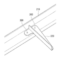
本実施形態の自動打鋲装置100は、図2に示すストリンガ210(縦通材)およびクリップ220からなる一対の被締結部材の打鋲位置P(図5等参照)にリベット300を打鋲する装置である。
ストリンガ210は、航空機の機軸方向に間隔を持って配置される長尺上の部材であり。クリップ220は、パネル状に分割された航空機の胴体を円筒状に保持するフレーム(図示略)とストリンガ210とを締結するための部材である。ストリンガ210およびクリップ220は、例えば、アルミニウム合金により形成されている。
Hereinafter, an
The
The
図2に示すように、ストリンガ210とクリップ220とは、例えばアルミニウム合金により形成されるリベット300によって締結されている。図2には、単一のクリップ220のみが示されているが、ストリンガ210には、長さ方向の複数箇所において複数のクリップ220が自動打鋲装置100によって締結される。
なお、ストリンガ210およびクリップ220は、自動打鋲装置100によって締結されるまでは、ロボットハンド等の把持装置(図示略)や仮止め用の固定器具等により相対位置が固定されるものとする。
As shown in FIG. 2, the
It is assumed that the relative positions of the
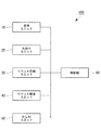
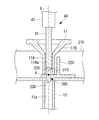
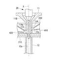
図1の概略構成に示すように、自動打鋲装置100は、支持ユニット10と、孔明けユニット20と、リベット供給ユニット30と、リベット吸着ユニット40と、かしめユニット50と、制御部60と、を備える。図1に示すように、制御部60とその他の各部とは、信号線を介して通信可能なように電気的に接続されている。
As shown in the schematic configuration of FIG. 1, the
なお、本実施形態において、図3および図4は、制御部60が実行する処理を示すフローチャートである。図5および図6は、支持ユニット10によるストリンガ210およびクリップ220を支持する動作を説明する縦断面図である。また、図7および図8は、孔明けユニット20によるストリンガ210およびクリップ220の孔明け動作を説明する縦断面図である。また、図9および図10は、リベット吸着ユニット40によるリベット300の挿入動作を説明する縦断面図である。また、図11から図14は、かしめユニット50によるリベット300のかしめ動作を説明する縦断面図である。
以下、自動打鋲装置100が備える各部について説明する。
In the present embodiment, FIGS. 3 and 4 are flowcharts showing processing executed by the
Hereinafter, each part with which the
支持ユニット10は、ストリンガ210およびクリップ220を、打鋲位置P(図5等参照)で挟むように支持する装置である。
支持ユニット10は、打鋲位置Pを通過する鉛直方向の軸線Xと同軸の位置に移動するとともに、軸線Xとは異なる軸線上に退避することが可能な移動機構(図示略)を有する。また、図5および図6に示すように、支持ユニット10は、軸線X上に同軸に配置された上側支持体(第1支持体)11および下側支持体(第2支持体)12を有する。
The
The
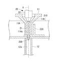
図5に示すように、上側支持体11は、軸線Xに沿って延びる貫通孔11Aaを有する棒状に形成された棒状部11Aと、棒状部11Aに連結されて棒状部11Aとの連結位置に近付くに連れて外径および内径が縮小する縮径部11Bとを備えており、クリップ220の上面を打鋲位置Pで支持する部材である。
縮径部11Bが連結位置に近付くに連れて外径及び内径が収縮する形状となっているのは、孔明けユニット20やかしめユニット50の軸受部との干渉を防止する為である。
下側支持体12は、軸線Xに沿って延びる貫通孔12aを有する棒状に形成されており、ストリンガ210の下面を打鋲位置Pで支持する部材である。
As shown in FIG. 5, the
The reason that the outer diameter and the inner diameter contract as the reduced
The
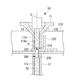
孔明けユニット20は、打鋲位置Pにおいてストリンガ210およびクリップ220に貫通孔230の孔明けを行う装置である。
図7および図8に示すように、孔明けユニット20は、先端および外周面に刃が形成されたドリル21と、ドリル21を軸線X回りに回転させるとともに軸線Xに沿って移動させる駆動部(図示略)が内蔵された本体部22とを有する。また、孔明けユニット20は、打鋲位置Pを通過する鉛直方向の軸線Xと同軸の位置に移動するとともに、軸線Xとは異なる軸線上に退避することが可能な移動機構(図示略)を有する。
The punching
As shown in FIGS. 7 and 8, the
リベット供給ユニット30は、リベット吸着ユニット40が吸着して打鋲位置Pの貫通孔230へ挿入するリベット300を供給する装置である。リベット供給ユニット30は、制御部60からの指示に従って、打鋲位置Pへ挿入するべきリベット300を多品種のリベット300の中から選択的に供給する。
The
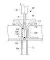
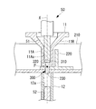
リベット吸着ユニット40は、図9および図10に示すように、軸線Xに沿って延びる円筒状に形成され、一端をリベット300の頭部310に接触させた状態で内部を負圧状態として頭部310を吸着させる装置である。リベット吸着ユニット40は、頭部310を吸着した状態でリベット300を搬送し、リベット300の軸部320を打鋲位置Pの貫通孔230へ挿入する。
As shown in FIGS. 9 and 10, the
リベット吸着ユニット40は、図9および図10に示すように、軸線Xに沿って延びる円筒状に形成されて先端側が開口した吸着軸41と、吸着軸41の基端側が取り付けられるとともに吸着軸41を軸線Xに沿って進退させる駆動機構(図示略)が内蔵されたシリンダ42と、を備える。また、リベット吸着ユニット40は、打鋲位置Pを通過する鉛直方向の軸線Xと同軸の位置に移動するとともに、軸線Xとは異なる軸線上に退避することが可能な移動機構(図示略)を有する。
As shown in FIGS. 9 and 10, the
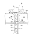
かしめユニット50は、貫通孔230にリベット300の軸部320が挿入された状態で、上側支持体11および下側支持体12に軸状の上部アンビル(かしめ部材)51および軸状の下部アンビル(かしめ部材)52を挿入し、これらを近接させてストリンガ210およびクリップ220をかしめる装置である。かしめユニット50は、打鋲位置Pを通過する鉛直方向の軸線Xと同軸の位置に移動するとともに、軸線Xとは異なる軸線上に退避することが可能な移動機構(図示略)を有する。
The
制御部60は、支持ユニット10と、孔明けユニット20と、リベット供給ユニット30と、リベット吸着ユニット40と、かしめユニット50と、を制御する装置である。
なお、制御部60は、例えば、CPU(Central Processing Unit)、RAM(Random Access Memory)、ROM(Read Only Memory)、及びコンピュータ読み取り可能な記憶媒体等から構成されている。そして、各種機能を実現するための一連の処理は、一例として、プログラムの形式で記憶媒体等に記憶されており、このプログラムをCPUがRAM等に読み出して、情報の加工・演算処理を実行することにより、各種機能が実現される。なお、プログラムは、ROMやその他の記憶媒体に予めインストールしておく形態や、コンピュータ読み取り可能な記憶媒体に記憶された状態で提供される形態、有線又は無線による通信手段を介して配信される形態等が適用されてもよい。コンピュータ読み取り可能な記憶媒体とは、磁気ディスク、光磁気ディスク、CD−ROM、DVD−ROM、半導体メモリ等である。
The
Note that the
次に、本実施形態の制御部60が実行する処理について、図3および図4を参照して説明する。
ステップS301で、制御部60は、支持ユニット10が打鋲位置Pを通過する鉛直方向の軸線Xと同軸の位置に移動するように移動機構(図示略)を制御する。ステップS301による支持ユニット10の移動が完了すると図5に示す状態となる。
Next, processing executed by the
In step S <b> 301, the
ステップS302で、制御部60は、上側支持体11および下側支持体12を互いに近接するように軸線Xに沿って移動させ、上側支持体11がクリップ220の上面を打鋲位置Pで支持し、下側支持体12がストリンガ210の下面を打鋲位置Pで支持した状態とする。ステップS302による支持動作が完了すると図6に示す状態となる。なお、支持ユニット10がストリンガ210およびクリップ220を打鋲位置Pで支持する状態は、後述するステップS312まで保持される。
In step S302, the
ステップS303で、制御部60は、孔明けユニット20が打鋲位置Pを通過する鉛直方向の軸線Xと同軸の位置に移動するように移動機構(図示略)を制御する。ステップS303による孔明けユニット20の移動が完了すると図7に示す状態となる。
In step S303, the
ステップS304で、制御部60は、孔明けユニット20を軸線Xに沿って下方に移動させてドリル21の先端を打鋲位置Pに突き当て、孔明け動作を実行する。ステップS303による孔明け動作が完了すると図8に示す状態となり、ストリンガ210およびクリップ220を貫通する貫通孔230が形成される。
ステップS305で、制御部60は、孔明けユニット20を軸線Xに沿った上方に移動させ、更に打鋲位置Pを通過する鉛直方向の軸線Xとは異なる他の軸線上の退避位置に退避するように移動機構(図示略)を制御する。
In step S304, the
In step S305, the
ステップS306で、制御部60は、リベット吸着ユニット40が打鋲位置Pを通過する鉛直方向の軸線Xと同軸の位置に移動するように移動機構(図示略)を制御する。ステップS306によるリベット吸着ユニット40の移動が完了すると図9に示す状態となる。
なお、図9に示すように、リベット吸着ユニット40は、円筒状の吸着軸41の先端にリベット300の頭部310を接触させて吸着軸41の内部を負圧状態とすることで、リベット300を吸着している。
In step S306, the
As shown in FIG. 9, the
ステップS307で、制御部60は、リベット300を吸着した状態で、吸着軸41をシリンダ42から軸線Xに沿って下方に突出させてリベット300の軸部320の先端を貫通孔230に挿入する挿入動作を実行する。ステップS307によるリベット300の挿入動作が完了すると図10に示す状態となる。
ステップS308で、制御部60は、リベット吸着ユニット40を軸線Xに沿った上方に移動させ、更に打鋲位置Pを通過する鉛直方向の軸線Xとは異なる他の軸線上の退避位置に退避するように移動機構(図示略)を制御する。
In step S307, with the
In step S308, the
ステップS309で、制御部60は、かしめユニット50が打鋲位置Pを通過する鉛直方向の軸線Xと同軸の位置に移動するように移動機構(図示略)を制御する。また、かしめユニット50の上部アンビル51を軸線Xに沿って下方に移動させ、上部アンビル51の先端部がリベット300の頭部310に突き当てられた状態とする。ステップS309によるかしめユニット50の移動が完了すると図11に示す状態となる。
In step S309, the
ステップS310で、制御部60は、かしめ動作を実行するようにかしめユニット50を制御する。
制御部60は、図12に示すように、かしめユニット50の上部アンビル51を軸線Xに沿って更に下方に移動させ、リベット300の頭部310の下面とクリップ220の上面とが接触した状態とする。なお、上部アンビル51は、後述するかしめ動作においてリベット300の頭部310の下面がクリップ220の上面から離間しないようにリベット300の頭部310の軸線X上の位置を保持する。
In step S310, the
As shown in FIG. 12, the
また、制御部60は、図13に示すように、かしめユニット50の下部アンビル52を軸線Xに沿って上方に移動させ、下部アンビル52の先端部がリベット300の軸部320の先端に突き当てられた状態とする。
また、制御部60は、図14に示すように、下部アンビル52を軸線Xに沿って更に上方に移動させ、金属製(例えば、アルミニウム合金製)のリベット300の軸部320を塑性変形させて貫通孔230の内径よりも大きい形状とする。
Further, as shown in FIG. 13, the
Further, as shown in FIG. 14, the
ステップS311で、制御部60は、上部アンビル51を軸線Xに沿って上方に移動させ、下部アンビル52を軸線Xに沿って下方に移動させ、更にこれらが打鋲位置Pを通過する鉛直方向の軸線Xとは異なる他の軸線上の退避位置に退避するように移動機構(図示略)を制御する。
In step S311, the
ステップS312で、制御部60は、かしめユニット50によるかしめ動作が終了し、ストリンガ210およびクリップ220が打鋲位置Pにおいてリベット300により締結されたため、支持ユニット10による支持を解除して支持ユニット10を退避させる。具体的には、制御部60は、上側支持体11および下側支持体12を互いに離間するように軸線Xに沿って移動させる。さらに、制御部60は、支持ユニット10が打鋲位置Pを通過する鉛直方向の軸線Xとは異なる他の軸線上の退避位置に退避するように移動機構(図示略)を制御する。
In step S312, the
ステップS313で、制御部60は、ステップS301−ステップS312による1つのリベット300の締結動作(孔明け動作、挿入動作、かしめ動作)が終了したことから、リベット300の打鋲を終了させるかどうかを判断する。
制御部60は、他のリベット300の締結動作を行う場合はNOと判断してステップS301−ステップS312の処理を他のリベット300について再び繰り返す。一方、制御部60は、他のリベット300の締結動作を行わない場合はYESと判断して本フローチャートの処理を終了させる。
In step S313, the
When performing the fastening operation of the
ここで、本実施形態の上側支持体11についてより詳細に説明する。
図15に示すように、上側支持体11には、下端側の外周面に切削屑を外部へ排出するための排出孔11aおよび排出孔11bが設けられている。
上側支持体11は、孔明けユニット20によりストリンガ210およびクリップ220の孔明け動作を行う際に、内部で生成される切削屑が排出孔11aおよび排出孔11bから外部へ排出可能となっている。切削屑を外部へ排出するためには、排出孔11a,11bの外周面にそれぞれ吸引部410,420を近づけ、吸引部410,420の内部に発生する負圧の作用によって切削屑を吸引部410,420の内部へ導く。
なお、本実施形態においては、上側支持体11に排出孔11aおよび排出孔11bを設ける態様としたが、上側支持体11に排出孔11aおよび排出孔11bを設けない態様とすることも可能である。例えば、発生した切削屑を取り除く為にドリルと貫通孔11Aaとの間に隙間を設け上側支持体11の縮径部11Bから切削屑を排出してもよい。
Here, the
As shown in FIG. 15, the
When the
In the present embodiment, the
ここで、本実施形態の自動打鋲装置100が備える検出装置70について説明する。検出装置70は、打鋲位置Pにおける法線方向を検出する装置である。検出装置70は、打鋲位置Pにおけるクリップ220の上面に対する自動打鋲装置100の各ユニット(図16に示す例は孔明けユニット20)の軸線方向を検出する装置である。図16に示す例において、孔明けユニット20が図中の破線で示す位置にある場合、検出装置70はクリップ220の上面に対する孔明けユニット20の軸線X1の角度を角度θ1として検出する。図16に示す角度θ1は、クリップ220の上面に対する法線(軸線X2)の角度である角度θ2(90°)とは一致していない。
Here, the
そこで、制御部60は、検出装置70が検出した角度θ1に基づいて、孔明けユニット20の軸線X1がクリップ220の上面に対する法線(軸線X2)と一致するように孔明けユニット20の移動機構を制御する。これにより、孔明けユニット20が図16中に実線で示す位置に移動し、孔明けユニット20の軸線X1が法線である軸線X2と一致する。このようにすることで、孔明けユニット20による孔明け動作をクリップ220の上面の法線方向から行い、法線方向に沿った貫通孔を形成することができる。
Therefore, the
なお、図16に示す例は、孔明けユニット20を法線方向に沿った位置に移動させるものであったが、支持ユニット10,リベット吸着ユニット40,かしめユニット50についても、これらを検出装置70が検出する角度に基づいて法線方向に沿った位置に移動させるようにしてもよい。
In the example shown in FIG. 16, the
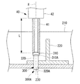
また、本実施形態のリベット吸着ユニット40がリベット300を離間させる位置について詳細に説明する。
本実施形態のリベット吸着ユニット40は、シリンダ42から吸着軸41の先端までの距離が一定のLとなった場合に、リベット300の軸部320を貫通孔230へ挿入した後に軸部320を離間させる。リベット吸着ユニット40は、シリンダ42から吸着軸41の先端までの距離が一定のLとなったことを検出する単一の着座センサ(図示略)を有しているものとする。
Further, the position where the
When the distance from the
単一の着座センサを有したリベット吸着ユニット40は、シリンダ42から吸着軸41の先端までの距離が一定のLとなったことのみを検出することができる。この場合、リベット吸着ユニット40が吸着するリベットの種類によって、貫通孔230に対するリベットの軸部の先端の位置等は異なったものとなる。例えば、図17中に実線で示すリベット300と破線で示すリベット300Aは、異なる形状となっている。そのため、リベット300Aの軸部320Aの下端の方が、リベット300の軸部320の下端よりも下方に配置される。同様に、リベット300Aの頭部310Aの下端の方が、リベット300の頭部310の下端よりも下方に配置される。
The
例えば、図17に示すリベット300とリベット300Aのように、多品種のリベットを扱う場合には、各リベットの頭部の下面がクリップ220の上面と接触した(着座した)ことを検出する着座センサを設けるのが最適である。しかしながら、この場合、多品種のリベットの複数の着座位置をそれぞれ検出するための複数の着座センサが必要となってしまう。一方、図17に示す変形例では、単一の着座センサのみで足りるため、複数の着座センサを設ける必要がない。また、単一の着座センサのみを用いる場合であっても、シリンダ42から吸着軸41の先端までの距離Lを適切に設定することにより、単一の着座センサのみを用いて、多品種のリベットをリベット吸着ユニット40から離間させる位置を適切に設定することができる。
For example, when handling a variety of rivets such as the
次に、本実施形態のかしめユニット50が備える上部アンビル51の形状について詳細に説明する。
図18に示すように、上部アンビル51の下端側の面には、凹所51aが形成されている。凹所51aの底面は平面形状となっている。一方、凹所51aに保持されるリベット300は、頭部310の上面が凹所51aの底面と接触する緩やかな凸面形状となっている。
また、凹所51aの底面は、リベット300Aの頭部310Aの上面との接触も可能となっている。ここで、リベット300Aの頭部310Aはリベット300の頭部310よりも小径である。このように、凹所51aは、異なる形状のリベット300,リベット300Aの双方に対応可能な形状となっている。このように、本実施形態のかしめユニット50が備える上部アンビル51は、多品種のリベットのかしめ動作を実行可能な形状となっている。
Next, the shape of the
As shown in FIG. 18, a
Further, the bottom surface of the
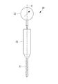
また、本実施形態の自動打鋲装置100の孔明けユニット20は、更に、孔明けユニット20が孔明けを行う際にストリンガ210およびクリップ220から受ける軸線Xの上方に向けた反力による変位量(押し戻し量の最大値)を測定する測定器23を備えるものであってもよい。
図19に示す測定器23は、孔明けユニット20による孔明け動作中に孔明けユニット20に与えられた反力による変位量(押し戻し量の最大値)を測定し、制御部60へ伝達する。変位量(押し戻し量の最大値)が大きい場合、孔明け動作により形成される貫通孔230の品質が低くなる可能性がある。これは、大きな反力によって貫通孔230の形状等に誤差が生じる可能性が高いためである。
Further, the punching
A measuring
本実施形態の自動打鋲装置100は、制御部60が、測定器23が測定する変位量(押し戻し量)と、その変位量を得た貫通孔230とを関連付けて記憶する。このようにすることで、打鋲位置Pでの締結状態の検査等をする場合に、貫通孔230の品質が低い可能性のある箇所を特定することができる。
In the
以上説明した本実施形態が奏する作用及び効果について説明する。
本実施形態の自動打鋲装置100によれば、相対位置が固定されたストリンガ210およびクリップ220のうちクリップ220が打鋲位置Pで上側支持体11により支持され、ストリンガ210が打鋲位置Pで下側支持体12により支持される。上側支持体11は、軸線Xに沿って延びる貫通孔11Aaを有する棒状に形成されており、円筒状に形成されるリベット吸着ユニット40に吸着したリベット300が挿入され、上部アンビル51が挿入される。
このように、本実施形態の自動打鋲装置100によれば、上側支持体11が軸線Xに沿って延びる貫通孔11Aaを有する棒状に形成されているため、打鋲位置Pが狭隘部であっても上側支持体11を適切に打鋲位置Pへ移動させることができる。
The operation and effects of the present embodiment described above will be described.
According to the
Thus, according to the
また、本実施形態の自動打鋲装置100によれば、リベット300を貫通孔230へ挿入してリベット吸着ユニット40を上側支持体11から退避させた後に上部アンビル51および下部アンビル52を近接させるため、リベット300の挿入とリベット300のかしめをそれぞれ独立した動作として行うことができる。そのため、リベット吸着ユニット40をリベット300の吸着に適した形状とし、かつ上部アンビル51をかしめに適した形状とすることができる。例えば、多品種のリベットをそれぞれ吸着可能な形状のリベット吸着ユニット40とし、多品種のリベットをそれぞれかしめ可能な形状の上部アンビル51とすることができる。
したがって、リベットの挿入とリベットのかしめを単一の部材を用いて行う場合に比べて、多品種のリベットを用いて打鋲を行うことが可能となり、打鋲を行う際の生産性が向上する。
Further, according to the
Therefore, compared to the case where rivets are inserted and rivets are caulked using a single member, it is possible to perform rivets using a variety of rivets, and productivity when performing rivets is improved. .
本実施形態の自動打鋲装置100は、制御部60が、ストリンガ210およびクリップ220に貫通孔230の孔明け動作を行うよう孔明けユニット20を制御し、孔明けユニット20が孔明け動作を行って打鋲位置Pから退避した後にリベット300の軸部320を打鋲位置Pに形成される貫通孔230へ挿入するようリベット吸着ユニット40を制御する。
このようにすることで、ストリンガ210およびクリップ220の打鋲位置Pに対して事前に他の装置で貫通孔230を形成しておく必要がないため、生産性が向上する。
In the
By doing in this way, since it is not necessary to form the through-
また、上側支持体11には、孔明けユニット20による孔明けにより生成される切削屑を排出するための排出孔11a,11bが形成されている。このようにすることで、孔明けユニット20による孔明け動作により生成される切削屑を排出孔11a,11bから吸引して外部へ排出し、貫通孔230を良好に仕上げることができる。
Further, the
また、本実施形態の自動打鋲装置100は、上側支持体11および下側支持体12によって相対位置が固定された被締結部材(ストリンガ210,クリップ220)が途中で分離されることなく継続的に支持された状態となる。そのため、孔明けからリベット300のかしめまでの一連の作業を、被締結部材が継続的に支持された状態で完了させることができるため、生産性が向上する。
Further, in the
10 支持ユニット
11 上側支持体(第1支持体)
11A 棒状部
11Aa 貫通孔
11B 縮径部
11a 排出孔
11b 排出孔
12 下側支持体(第2支持体)
20 孔明けユニット(孔明け部)
21 ドリル
22 本体部
23 計測器
30 リベット供給ユニット
40 リベット吸着ユニット(リベット吸着部)
41 吸着軸
42 シリンダ
50 かしめユニット(かしめ部)
51 上部アンビル(かしめ部材)
51a 凹所
52 下部アンビル(かしめ部材)
60 制御部
70 検出装置
100 自動打鋲装置
210 ストリンガ(縦通材)
220 クリップ
230 貫通孔
300 リベット
310 頭部
320 軸部
410,420 吸引部
P 打鋲位置
X,X1,X2 軸線
θ1,θ2 角度
10
11A Rod-like part 11Aa Through
20 Drilling unit (drilling part)
21
41
51 Upper anvil (caulking member)
60
220
Claims (5)
軸線に沿って延びる貫通孔を有する棒状に形成されて前記一対の被締結部材の一方を前記打鋲位置で支持する第1支持体と、
前記軸線に沿って延びる貫通孔を有する棒状に形成されて前記一対の被締結部材の他方を前記打鋲位置で支持する第2支持体と、
前記軸線に沿って延びる円筒状に形成され、一端を前記リベットの頭部に接触させた状態で内部を負圧状態として該頭部を吸着させるリベット吸着部と、
前記一対の被締結部材の前記打鋲位置に形成される貫通孔に前記リベットが挿入された状態で、前記第1支持体および前記第2支持体に一対の軸状のかしめ部材を挿入し、該一対のかしめ部材を近接させて前記リベットにより前記一対の被締結部材をかしめるかしめ部と、
前記リベット吸着部および前記かしめ部を制御する制御部と、を備え、
前記制御部が、
前記リベットの前記頭部を吸着させた前記リベット吸着部を前記第1支持体へ移動させて前記リベットの軸部を前記打鋲位置に形成される前記貫通孔へ挿入するよう前記リベット吸着部を制御し、
該リベット吸着部が前記リベットを前記貫通孔へ挿入して前記打鋲位置から退避した後に前記一対のかしめ部材を近接させて前記リベットにより前記一対の被締結部材をかしめるように前記かしめ部を制御する打鋲装置。 A striking device for striking a rivet at a striking position of a pair of fastened members whose relative positions are fixed,
A first support body that is formed in a rod shape having a through hole extending along an axis and supports one of the pair of fastened members at the striking position;
A second support formed in a rod shape having a through hole extending along the axis and supporting the other of the pair of fastened members at the striking position;
A rivet adsorbing portion that is formed in a cylindrical shape extending along the axis, and that adsorbs the head with a negative pressure inside the rivet in a state where one end is in contact with the head of the rivet;
In a state where the rivet is inserted into a through hole formed at the striking position of the pair of fastened members, a pair of shaft-shaped caulking members are inserted into the first support body and the second support body, A caulking portion that causes the pair of caulking members to approach each other and caulks the pair of fastened members with the rivets;
A control unit for controlling the rivet adsorbing unit and the caulking unit,
The control unit is
The rivet adsorbing part is moved so that the rivet adsorbing part adsorbing the head part of the rivet is moved to the first support and the shaft part of the rivet is inserted into the through hole formed at the striking position. Control
After the rivet adsorbing portion inserts the rivet into the through hole and retracts from the striking position, the pair of caulking members are brought close to each other and the caulking portion is caulked by the rivet to caulk the pair of fastened members. Striking device to control.
前記制御部が、前記第1支持体および前記第2支持体により前記打鋲位置で支持された前記一対の被締結部材に前記貫通孔の孔明けを行うよう前記孔明け部を制御し、
前記孔明け部が前記貫通孔の孔明けを行って前記打鋲位置から退避した後に前記リベットの軸部を前記打鋲位置に形成される前記貫通孔へ挿入するよう前記リベット吸着部を制御する請求項1に記載の打鋲装置。 In the striking position, provided with a drilling portion for drilling the through hole in the pair of fastened members,
The control unit controls the perforating portion to perforate the through hole in the pair of fastened members supported at the striking position by the first support body and the second support body;
The rivet adsorbing portion is controlled so that the shaft portion of the rivet is inserted into the through hole formed at the striking position after the perforating portion has perforated the retraction hole and retracted from the striking position. The striking device according to claim 1.
前記制御部は、前記測定器が測定する前記変位量と、該変位量を得た前記貫通孔とを関連付けて記憶する請求項2または請求項3に記載の打鋲装置。 The perforated part includes a measuring instrument that measures a displacement amount due to a reaction force received from the fastened member when the through hole is perforated,
The striking device according to claim 2 or 3, wherein the control unit stores the displacement amount measured by the measuring instrument in association with the through hole from which the displacement amount is obtained.
前記打鋲装置が、
軸線に沿って延びる貫通孔を有する棒状に形成されて前記一対の被締結部材の一方を前記打鋲位置で支持する第1支持体と、
前記軸線に沿って延びる貫通孔を有する棒状に形成されて前記一対の被締結部材の他方を前記打鋲位置で支持する第2支持体と、
前記軸線に沿って延びる円筒状に形成され、一端を前記リベットの頭部に接触させた状態で内部を負圧状態として該頭部を吸着させるリベット吸着部と、
前記一対の被締結部材の前記打鋲位置に形成される貫通孔に前記リベットが挿入された状態で、前記第1支持体および前記第2支持体に一対のかしめ部材を挿入し、該一対のかしめ部材を近接させて前記リベットにより前記一対の被締結部材をかしめるかしめ部と、を備え、
前記リベットの前記頭部を吸着させた前記リベット吸着部を前記第1支持体へ移動させて前記リベットの軸部を前記打鋲位置に形成される前記貫通孔へ挿入するよう前記リベット吸着部を制御する第1制御工程と、
該リベット吸着部が前記リベットを前記貫通孔へ挿入して前記打鋲位置から退避した後に前記一対のかしめ部材を近接させて前記リベットにより前記一対の被締結部材をかしめるように前記かしめ部を制御する第2制御工程と、を備える打鋲装置の制御方法。 A control method for a striking device for striking a rivet at a striking position of a pair of fastened members whose relative positions are fixed,
The striking device is
A first support body that is formed in a rod shape having a through hole extending along an axis and supports one of the pair of fastened members at the striking position;
A second support formed in a rod shape having a through hole extending along the axis and supporting the other of the pair of fastened members at the striking position;
A rivet adsorbing portion that is formed in a cylindrical shape extending along the axis, and that adsorbs the head with a negative pressure inside the rivet in a state where one end is in contact with the head of the rivet;
A pair of caulking members are inserted into the first support body and the second support body in a state where the rivet is inserted into a through-hole formed at the striking position of the pair of fastened members, A caulking portion for caulking the caulking member and caulking the pair of fastened members with the rivet,
The rivet adsorbing part is moved so that the rivet adsorbing part adsorbing the head part of the rivet is moved to the first support and the shaft part of the rivet is inserted into the through hole formed at the striking position. A first control step to control;
After the rivet adsorbing portion inserts the rivet into the through hole and retracts from the striking position, the pair of caulking members are brought close to each other and the caulking portion is caulked by the rivet to caulk the pair of fastened members. A control method of a striking device comprising: a second control step of controlling.
Priority Applications (5)
| Application Number | Priority Date | Filing Date | Title |
|---|---|---|---|
| JP2016101942A JP2017205802A (en) | 2016-05-20 | 2016-05-20 | Riveting device and control method thereof |
| EP17799528.9A EP3437755B1 (en) | 2016-05-20 | 2017-05-19 | Riveting machine and control method for same |
| CN201780026955.6A CN109070187A (en) | 2016-05-20 | 2017-05-19 | Riveting set and its control method |
| PCT/JP2017/018936 WO2017200104A1 (en) | 2016-05-20 | 2017-05-19 | Riveting machine and control method for same |
| US16/097,637 US10940525B2 (en) | 2016-05-20 | 2017-05-19 | Riveting machine and control method for same |
Applications Claiming Priority (1)
| Application Number | Priority Date | Filing Date | Title |
|---|---|---|---|
| JP2016101942A JP2017205802A (en) | 2016-05-20 | 2016-05-20 | Riveting device and control method thereof |
Publications (1)
| Publication Number | Publication Date |
|---|---|
| JP2017205802A true JP2017205802A (en) | 2017-11-24 |
Family
ID=60325449
Family Applications (1)
| Application Number | Title | Priority Date | Filing Date |
|---|---|---|---|
| JP2016101942A Pending JP2017205802A (en) | 2016-05-20 | 2016-05-20 | Riveting device and control method thereof |
Country Status (5)
| Country | Link |
|---|---|
| US (1) | US10940525B2 (en) |
| EP (1) | EP3437755B1 (en) |
| JP (1) | JP2017205802A (en) |
| CN (1) | CN109070187A (en) |
| WO (1) | WO2017200104A1 (en) |
Cited By (5)
| Publication number | Priority date | Publication date | Assignee | Title |
|---|---|---|---|---|
| WO2020105552A1 (en) * | 2018-11-22 | 2020-05-28 | 三菱重工業株式会社 | Clamping method and clamping device |
| JP2020121398A (en) * | 2018-12-21 | 2020-08-13 | ザ・ボーイング・カンパニーThe Boeing Company | Method and apparatus for single-sided clamp-up |
| JP2022121126A (en) * | 2021-02-08 | 2022-08-19 | 三菱重工業株式会社 | Support unit and riveting device |
| US11745250B2 (en) | 2020-06-05 | 2023-09-05 | Mitsubishi Heavy Industries, Ltd. | Swaging device and swaging method |
| US12397341B2 (en) | 2020-06-23 | 2025-08-26 | Mitsubishi Heavy Industries, Ltd. | Riveting device and riveting method |
Families Citing this family (6)
| Publication number | Priority date | Publication date | Assignee | Title |
|---|---|---|---|---|
| IT201800011097A1 (en) * | 2018-12-14 | 2020-06-14 | Cosberg Spa | RIVETING DEVICE FOR ASSEMBLY PLANTS |
| CA3170365A1 (en) * | 2020-02-08 | 2021-08-12 | Jr Automation Technologies, Llc | Rivet fastener apparatus |
| GB2627511B (en) * | 2023-02-24 | 2025-05-07 | Airbus Operations Ltd | Self aligning system |
| CN117259658B (en) * | 2023-10-11 | 2024-06-14 | 南通中兴轴承有限公司 | Riveting device for automobile clutch release bearing and use method |
| CN117564695A (en) * | 2023-12-12 | 2024-02-20 | 芜湖东光大华机械制造有限公司 | An automatic assembly equipment for automobile flywheel assembly |
| CN118404346A (en) * | 2024-05-21 | 2024-07-30 | 西安兴航航空科技股份有限公司 | A gantry type automatic drilling and riveting machine |
Citations (6)
| Publication number | Priority date | Publication date | Assignee | Title |
|---|---|---|---|---|
| JPH02244517A (en) * | 1989-03-17 | 1990-09-28 | Tanaka Kikinzoku Kogyo Kk | Method of transport and insertion of rivet type contact into recess in base |
| JPH03285736A (en) * | 1990-03-30 | 1991-12-16 | It Mach Tool Agency Inc | Robot-controlled multi-task type end effector |
| JPH0483549U (en) * | 1990-11-30 | 1992-07-21 | ||
| JP2002263777A (en) * | 2001-01-15 | 2002-09-17 | Emhart Inc | Method for rivet-connection or punching-out and apparatus for performing this method |
| JP2003010941A (en) * | 2001-06-29 | 2003-01-15 | Japan Aircraft Mfg Co Ltd | Riveting device |
| JP2003231042A (en) * | 2002-02-08 | 2003-08-19 | Kawasaki Heavy Ind Ltd | Hole imaging device and processing device |
Family Cites Families (13)
| Publication number | Priority date | Publication date | Assignee | Title |
|---|---|---|---|---|
| US4901431A (en) * | 1988-06-06 | 1990-02-20 | Textron Inc. | Powered fastener installation apparatus |
| US4955119A (en) * | 1989-07-11 | 1990-09-11 | Imta | Multi-task end effector for robotic machining center |
| US5213454A (en) * | 1990-12-21 | 1993-05-25 | The Boeing Company | Apparatus for chip vacuum, mist lubrication and coil cooling |
| JP2516366Y2 (en) * | 1991-05-22 | 1996-11-06 | プレス工業株式会社 | Rivet caulking device with rivet head detection mechanism |
| JPH0686838U (en) * | 1993-05-21 | 1994-12-20 | 弘之 石川 | Riveting machine |
| JP2980240B1 (en) * | 1998-07-22 | 1999-11-22 | 西松建設株式会社 | Medium pressure detector |
| JP4379656B2 (en) | 2000-03-23 | 2009-12-09 | 日本飛行機株式会社 | Crushing apparatus and crushing method |
| ATE416050T1 (en) * | 2002-01-21 | 2008-12-15 | Ms Geraetebau Gmbh | SETTING TOOL WITH MEANS FOR CONTROLLING SETTING PROCESSES |
| CN201470805U (en) * | 2009-07-16 | 2010-05-19 | 郑州航天电子技术有限公司 | Riveting machine |
| US9021677B1 (en) * | 2012-01-12 | 2015-05-05 | Gemcor Ii, Llc | Apparatus and method for improving safety and quality of automatic riveting operations |
| JP5851868B2 (en) | 2012-02-03 | 2016-02-03 | 三菱重工業株式会社 | Bar-shaped member chucking device and bar-shaped member chucking method |
| CN103567350A (en) * | 2012-07-30 | 2014-02-12 | 成都飞机工业(集团)有限责任公司 | Method for preventing automatic drilling and riveting machine from no-rivet riveting or crooked rivet riveting |
| CN104399859B (en) * | 2014-11-25 | 2016-07-06 | 眉山南车紧固件科技有限公司 | Thin plate self-locking is solidly connected method and system |
-
2016
- 2016-05-20 JP JP2016101942A patent/JP2017205802A/en active Pending
-
2017
- 2017-05-19 WO PCT/JP2017/018936 patent/WO2017200104A1/en not_active Ceased
- 2017-05-19 EP EP17799528.9A patent/EP3437755B1/en active Active
- 2017-05-19 US US16/097,637 patent/US10940525B2/en active Active
- 2017-05-19 CN CN201780026955.6A patent/CN109070187A/en active Pending
Patent Citations (6)
| Publication number | Priority date | Publication date | Assignee | Title |
|---|---|---|---|---|
| JPH02244517A (en) * | 1989-03-17 | 1990-09-28 | Tanaka Kikinzoku Kogyo Kk | Method of transport and insertion of rivet type contact into recess in base |
| JPH03285736A (en) * | 1990-03-30 | 1991-12-16 | It Mach Tool Agency Inc | Robot-controlled multi-task type end effector |
| JPH0483549U (en) * | 1990-11-30 | 1992-07-21 | ||
| JP2002263777A (en) * | 2001-01-15 | 2002-09-17 | Emhart Inc | Method for rivet-connection or punching-out and apparatus for performing this method |
| JP2003010941A (en) * | 2001-06-29 | 2003-01-15 | Japan Aircraft Mfg Co Ltd | Riveting device |
| JP2003231042A (en) * | 2002-02-08 | 2003-08-19 | Kawasaki Heavy Ind Ltd | Hole imaging device and processing device |
Cited By (10)
| Publication number | Priority date | Publication date | Assignee | Title |
|---|---|---|---|---|
| WO2020105552A1 (en) * | 2018-11-22 | 2020-05-28 | 三菱重工業株式会社 | Clamping method and clamping device |
| JP2020082260A (en) * | 2018-11-22 | 2020-06-04 | 三菱重工業株式会社 | Clamp method and clamp device |
| JP7191657B2 (en) | 2018-11-22 | 2022-12-19 | 三菱重工業株式会社 | Clamping method and clamping device |
| US12059722B2 (en) | 2018-11-22 | 2024-08-13 | Mitsubishi Heavy Industries, Ltd. | Clamping method and clamping device |
| JP2020121398A (en) * | 2018-12-21 | 2020-08-13 | ザ・ボーイング・カンパニーThe Boeing Company | Method and apparatus for single-sided clamp-up |
| JP7548695B2 (en) | 2018-12-21 | 2024-09-10 | ザ・ボーイング・カンパニー | Method and apparatus for one-sided initiated pressure welding |
| US11745250B2 (en) | 2020-06-05 | 2023-09-05 | Mitsubishi Heavy Industries, Ltd. | Swaging device and swaging method |
| US12397341B2 (en) | 2020-06-23 | 2025-08-26 | Mitsubishi Heavy Industries, Ltd. | Riveting device and riveting method |
| JP2022121126A (en) * | 2021-02-08 | 2022-08-19 | 三菱重工業株式会社 | Support unit and riveting device |
| JP7326360B2 (en) | 2021-02-08 | 2023-08-15 | 三菱重工業株式会社 | Support unit and riveting device |
Also Published As
| Publication number | Publication date |
|---|---|
| EP3437755A4 (en) | 2019-05-01 |
| EP3437755B1 (en) | 2020-04-01 |
| CN109070187A (en) | 2018-12-21 |
| WO2017200104A1 (en) | 2017-11-23 |
| US10940525B2 (en) | 2021-03-09 |
| US20190134699A1 (en) | 2019-05-09 |
| EP3437755A1 (en) | 2019-02-06 |
Similar Documents
| Publication | Publication Date | Title |
|---|---|---|
| JP2017205802A (en) | Riveting device and control method thereof | |
| US7559136B2 (en) | Press for attaching nuts to pipes | |
| JP6026340B2 (en) | Assembly apparatus and control method | |
| US8434215B2 (en) | Self-piercing rivet setting machine | |
| US11040783B2 (en) | Component manufacturing method and component manufacturing system | |
| CN111788023B (en) | Riveting machine and riveting method | |
| CN112823067B (en) | Riveting method | |
| WO2019110992A1 (en) | Nose arrangements for fastener setting machines, and related methods | |
| CN104722663A (en) | Cam assembly machine | |
| KR102378841B1 (en) | Slew-actuated piercing of radial walls | |
| US20120317767A1 (en) | Die for rivet machine | |
| JPH04256526A (en) | Position detecting method for assembly parts | |
| US9789531B2 (en) | Fastener applying apparatus and fastener applying method | |
| ES2274401T3 (en) | AUTOMATIC DEVICE TO TAKE A TOOL FROM A BATTERY OF TOOLS AND TO DEPOSIT IT IN IT. | |
| CN104505244B (en) | Automatic shaping machine applied to manufacturing of transformer | |
| TWI906478B (en) | Method for operating a machine for laser cutting of tubes and profiled sections | |
| JP3984066B2 (en) | Hole imaging device and processing device | |
| EP1329270A1 (en) | Device for riveting longitudinal reinforcing members onto aluminium panels | |
| JP7331250B2 (en) | Drilling device and drilling method | |
| JP3301290B2 (en) | Riveting tools | |
| JP2017167062A (en) | Concrete core sampling device | |
| CN101961875A (en) | Puncher | |
| JP2010075961A (en) | Consecutive riveter | |
| CN113263202A (en) | Intelligent processing equipment for inner hole of valve stem | |
| JP2001269823A (en) | Riveting apparatus and riveting method |
Legal Events
| Date | Code | Title | Description |
|---|---|---|---|
| A521 | Request for written amendment filed |
Free format text: JAPANESE INTERMEDIATE CODE: A523 Effective date: 20170914 |
|
| A711 | Notification of change in applicant |
Free format text: JAPANESE INTERMEDIATE CODE: A711 Effective date: 20170914 |
|
| A521 | Request for written amendment filed |
Free format text: JAPANESE INTERMEDIATE CODE: A821 Effective date: 20170914 |
|
| A621 | Written request for application examination |
Free format text: JAPANESE INTERMEDIATE CODE: A621 Effective date: 20190219 |
|
| A131 | Notification of reasons for refusal |
Free format text: JAPANESE INTERMEDIATE CODE: A131 Effective date: 20200204 |
|
| A521 | Request for written amendment filed |
Free format text: JAPANESE INTERMEDIATE CODE: A523 Effective date: 20200406 |
|
| A02 | Decision of refusal |
Free format text: JAPANESE INTERMEDIATE CODE: A02 Effective date: 20200428 |