JP2017204742A - Terminal device, base station device, communication method, and program - Google Patents
Terminal device, base station device, communication method, and program Download PDFInfo
- Publication number
- JP2017204742A JP2017204742A JP2016095529A JP2016095529A JP2017204742A JP 2017204742 A JP2017204742 A JP 2017204742A JP 2016095529 A JP2016095529 A JP 2016095529A JP 2016095529 A JP2016095529 A JP 2016095529A JP 2017204742 A JP2017204742 A JP 2017204742A
- Authority
- JP
- Japan
- Prior art keywords
- uplink
- physical channel
- serving cell
- uplink physical
- transmission power
- Prior art date
- Legal status (The legal status is an assumption and is not a legal conclusion. Google has not performed a legal analysis and makes no representation as to the accuracy of the status listed.)
- Granted
Links
Images


Classifications
-
- H—ELECTRICITY
- H04—ELECTRIC COMMUNICATION TECHNIQUE
- H04W—WIRELESS COMMUNICATION NETWORKS
- H04W52/00—Power management, e.g. TPC [Transmission Power Control], power saving or power classes
- H04W52/04—TPC
- H04W52/06—TPC algorithms
- H04W52/14—Separate analysis of uplink or downlink
-
- H—ELECTRICITY
- H04—ELECTRIC COMMUNICATION TECHNIQUE
- H04W—WIRELESS COMMUNICATION NETWORKS
- H04W52/00—Power management, e.g. TPC [Transmission Power Control], power saving or power classes
- H04W52/04—TPC
- H04W52/06—TPC algorithms
- H04W52/14—Separate analysis of uplink or downlink
- H04W52/146—Uplink power control
-
- H—ELECTRICITY
- H04—ELECTRIC COMMUNICATION TECHNIQUE
- H04W—WIRELESS COMMUNICATION NETWORKS
- H04W52/00—Power management, e.g. TPC [Transmission Power Control], power saving or power classes
- H04W52/04—TPC
- H04W52/18—TPC being performed according to specific parameters
-
- H—ELECTRICITY
- H04—ELECTRIC COMMUNICATION TECHNIQUE
- H04W—WIRELESS COMMUNICATION NETWORKS
- H04W52/00—Power management, e.g. TPC [Transmission Power Control], power saving or power classes
- H04W52/04—TPC
- H04W52/30—TPC using constraints in the total amount of available transmission power
-
- H—ELECTRICITY
- H04—ELECTRIC COMMUNICATION TECHNIQUE
- H04W—WIRELESS COMMUNICATION NETWORKS
- H04W52/00—Power management, e.g. TPC [Transmission Power Control], power saving or power classes
- H04W52/04—TPC
- H04W52/30—TPC using constraints in the total amount of available transmission power
- H04W52/36—TPC using constraints in the total amount of available transmission power with a discrete range or set of values, e.g. step size, ramping or offsets
- H04W52/367—Power values between minimum and maximum limits, e.g. dynamic range
-
- H—ELECTRICITY
- H04—ELECTRIC COMMUNICATION TECHNIQUE
- H04W—WIRELESS COMMUNICATION NETWORKS
- H04W52/00—Power management, e.g. TPC [Transmission Power Control], power saving or power classes
- H04W52/04—TPC
- H04W52/38—TPC being performed in particular situations
-
- H—ELECTRICITY
- H04—ELECTRIC COMMUNICATION TECHNIQUE
- H04W—WIRELESS COMMUNICATION NETWORKS
- H04W72/00—Local resource management
- H04W72/04—Wireless resource allocation
-
- H—ELECTRICITY
- H04—ELECTRIC COMMUNICATION TECHNIQUE
- H04W—WIRELESS COMMUNICATION NETWORKS
- H04W72/00—Local resource management
- H04W72/04—Wireless resource allocation
- H04W72/044—Wireless resource allocation based on the type of the allocated resource
-
- H—ELECTRICITY
- H04—ELECTRIC COMMUNICATION TECHNIQUE
- H04W—WIRELESS COMMUNICATION NETWORKS
- H04W88/00—Devices specially adapted for wireless communication networks, e.g. terminals, base stations or access point devices
- H04W88/02—Terminal devices
- H04W88/06—Terminal devices adapted for operation in multiple networks or having at least two operational modes, e.g. multi-mode terminals
Landscapes
- Engineering & Computer Science (AREA)
- Computer Networks & Wireless Communication (AREA)
- Signal Processing (AREA)
- Mobile Radio Communication Systems (AREA)
Abstract
Description
本開示は、端末装置、基地局装置、通信方法、及びプログラムに関する。 The present disclosure relates to a terminal device, a base station device, a communication method, and a program.
セルラー移動通信の無線アクセス方式および無線ネットワーク(以下、「Long Term Evolution(LTE)」、「LTE-Advanced(LTE-A)」、「LTE-Advanced Pro(LTE-A Pro)」、「New Radio(NR)」、「New Radio Access Technology(NRAT)」、「Evolved Universal Terrestrial Radio Access(EUTRA)」、または「Further EUTRA(FEUTRA)」とも称する。)が、第三世代パートナーシッププロジェクト(3rd Generation Partnership Project: 3GPP)において検討されている。なお、以下の説明において、LTEは、LTE-A、LTE-A Pro、およびEUTRAを含み、NRは、NRAT、およびFEUTRAを含む。LTEおよびNRでは、基地局装置(基地局)はeNodeB(evolved NodeB)、端末装置(移動局、移動局装置、端末)はUE(User Equipment)とも称する。LTEおよびNRは、基地局装置がカバーするエリアをセル状に複数配置するセルラー通信システムである。単一の基地局装置は複数のセルを管理してもよい。 Wireless access methods and networks for cellular mobile communications (Long Term Evolution (LTE), LTE-Advanced (LTE-A), LTE-Advanced Pro (LTE-A Pro)), New Radio ( NR), “New Radio Access Technology (NRAT)”, “Evolved Universal Terrestrial Radio Access (EUTRA)”, or “Further EUTRA (FEUTRA)”), the 3rd Generation Partnership Project: 3GPP). In the following description, LTE includes LTE-A, LTE-A Pro, and EUTRA, and NR includes NRAT and FEUTRA. In LTE and NR, a base station device (base station) is also called eNodeB (evolved NodeB), and a terminal device (mobile station, mobile station device, terminal) is also called UE (User Equipment). LTE and NR are cellular communication systems in which a plurality of areas covered by a base station apparatus are arranged in a cell shape. A single base station apparatus may manage a plurality of cells.
NRは、LTEに対する次世代の無線アクセス方式として、LTEとは異なるRAT(Radio Access Technology)である。NRは、eMBB(Enhanced mobile broadband)、mMTC(Massive machine type communications)およびURLLC(Ultra reliable and low latency communications)を含む様々なユースケースに対応できるアクセス技術である。NRは、それらのユースケースにおける利用シナリオ、要求条件、および配置シナリオなどに対応する技術フレームワークを目指して検討される。NRのシナリオや要求条件の詳細は、非特許文献1に開示されている。
NR is a radio access technology (RAT) different from LTE as a next-generation radio access scheme for LTE. NR is an access technology that can handle various use cases including eMBB (Enhanced mobile broadband), mMTC (Massive machine type communications), and URLLC (Ultra reliable and low latency communications). NR is examined with the aim of a technology framework that addresses usage scenarios, requirements, and deployment scenarios in those use cases. Details of NR scenarios and requirements are disclosed in
無線アクセス技術において、サブキャリア間隔やシンボル長のような送信信号や下りリンク物理チャネルや上りリンク物理チャネルをマップする無線フレームの定義などのパラメータ(物理パラメータ)は、ユースケースに応じて柔軟に設計されることが好ましい。そして、周波数利用効率の観点から、その柔軟に設計された複数の無線アクセス技術の多重を行うことが重要である。従来は、同一の無線リソースの定義による無線アクセス技術の多重のみ検討されていた。しかしながら、異なる無線リソースの定義による無線アクセス技術の多重は想定されていないため、異なる無線リソースの定義の無線アクセス技術を多重することが困難である。 In radio access technology, parameters (physical parameters) such as the definition of radio signals that map transmission signals, downlink physical channels, and uplink physical channels, such as subcarrier intervals and symbol length, are flexibly designed according to use cases. It is preferred that From the viewpoint of frequency utilization efficiency, it is important to multiplex a plurality of radio access technologies designed flexibly. Conventionally, only multiplexing of radio access technologies based on the same radio resource definition has been studied. However, since multiplexing of radio access technologies based on different radio resource definitions is not assumed, it is difficult to multiplex radio access technologies defined with different radio resources.
そこで、本開示では、基地局装置と端末装置が通信する通信システムにおいて、システム全体の伝送効率をより向上させることが可能な、基端末装置、基地局装置、通信方法、及びプログラムを提案する。 Therefore, the present disclosure proposes a base terminal device, a base station device, a communication method, and a program that can further improve the transmission efficiency of the entire system in a communication system in which a base station device and a terminal device communicate.
本開示によれば、無線通信を行う通信部と、サブフレーム長が互いに異なる第1のサービングセルおよび第2のサービングセルそれぞれとの間の通信のための電力を割り当てる制御部と、を備え、前記制御部は、前記第1のサービングセルで発生する第1の上りリンク物理チャネルの送信電力を、第1の時間単位に基づいて計算し、前記第2のサービングセルで発生する第2の上りリンク物理チャネルの送信電力を、第2の時間単位に基づいて計算する、端末装置が提供される。 According to the present disclosure, the control unit includes a communication unit that performs wireless communication, and a control unit that allocates power for communication between the first serving cell and the second serving cell having different subframe lengths. The unit calculates the transmission power of the first uplink physical channel generated in the first serving cell based on a first time unit, and calculates the transmission power of the second uplink physical channel generated in the second serving cell. A terminal device is provided that calculates transmission power based on a second time unit.
また、本開示によれば、無線通信を行う通信部と、サブフレーム長が互いに異なる第1のサービングセルおよび第2のサービングセルを設定する制御部と、を備え、前記制御部は、前記第1のサービングセルで発生する第1の上りリンク物理チャネルの送信電力を算出するための第1の単位時間を設定し、前記第2のサービングセルで発生する第2の上りリンク物理チャネルの送信電力を算出するための第2の単位時間を設定する、基地局装置が提供される。 In addition, according to the present disclosure, a communication unit that performs wireless communication, and a control unit that sets a first serving cell and a second serving cell that have different subframe lengths, the control unit includes the first To set a first unit time for calculating the transmission power of the first uplink physical channel generated in the serving cell and to calculate the transmission power of the second uplink physical channel generated in the second serving cell A base station apparatus for setting the second unit time is provided.
また、本開示によれば、無線通信を行うことと、プロセッサが、サブフレーム長が互いに異なる第1のサービングセルおよび第2のサービングセルそれぞれとの間の通信のための電力を割り当てることと、前記第1のサービングセルで発生する第1の上りリンク物理チャネルの送信電力を、第1の時間単位に基づいて計算することと、前記第2のサービングセルで発生する第2の上りリンク物理チャネルの送信電力を、第2の時間単位に基づいて計算することと、を含む、通信方法が提供される。 Further, according to the present disclosure, performing wireless communication, a processor allocating power for communication between each of the first serving cell and the second serving cell having different subframe lengths, and the first Calculating transmission power of a first uplink physical channel generated in one serving cell based on a first time unit; and transmitting power of a second uplink physical channel generated in the second serving cell. And calculating based on a second time unit.
また、本開示によれば、無線通信を行うことと、プロセッサが、サブフレーム長が互いに異なる第1のサービングセルおよび第2のサービングセルを設定することと、前記第1のサービングセルで発生する第1の上りリンク物理チャネルの送信電力を算出するための第1の単位時間を設定することと、前記第2のサービングセルで発生する第2の上りリンク物理チャネルの送信電力を算出するための第2の単位時間を設定することと、を含む、通信方法が提供される。 In addition, according to the present disclosure, the wireless communication, the processor sets the first serving cell and the second serving cell having different subframe lengths, and the first generated in the first serving cell. Setting a first unit time for calculating the transmission power of the uplink physical channel and a second unit for calculating the transmission power of the second uplink physical channel generated in the second serving cell Setting a time is provided.
また、本開示によれば、コンピュータに、無線通信を行うことと、サブフレーム長が互いに異なる第1のサービングセルおよび第2のサービングセルそれぞれとの間の通信のための電力を割り当てることと、前記第1のサービングセルで発生する第1の上りリンク物理チャネルの送信電力を、第1の時間単位に基づいて計算することと、前記第2のサービングセルで発生する第2の上りリンク物理チャネルの送信電力を、第2の時間単位に基づいて計算することと、を実行させる、プログラムが提供される。 According to the present disclosure, the computer performs wireless communication, allocates power for communication between each of the first serving cell and the second serving cell having different subframe lengths, and the first Calculating transmission power of a first uplink physical channel generated in one serving cell based on a first time unit; and transmitting power of a second uplink physical channel generated in the second serving cell. A program is provided for performing the calculation based on the second time unit.
また、本開示によれば、コンピュータに、無線通信を行うことと、サブフレーム長が互いに異なる第1のサービングセルおよび第2のサービングセルを設定することと、前記第1のサービングセルで発生する第1の上りリンク物理チャネルの送信電力を算出するための第1の単位時間を設定することと、前記第2のサービングセルで発生する第2の上りリンク物理チャネルの送信電力を算出するための第2の単位時間を設定することと、を実行させる、プログラムが提供される。 In addition, according to the present disclosure, the computer performs wireless communication, sets the first serving cell and the second serving cell with different subframe lengths, and the first generated in the first serving cell. Setting a first unit time for calculating the transmission power of the uplink physical channel and a second unit for calculating the transmission power of the second uplink physical channel generated in the second serving cell A program is provided for setting and executing time.
以上説明したように本開示によれば、基地局装置と端末装置が通信する通信システムにおいて、システム全体の伝送効率をより向上させることが可能な、基端末装置、基地局装置、通信方法、及びプログラムが提供される。 As described above, according to the present disclosure, in a communication system in which a base station device and a terminal device communicate, a base terminal device, a base station device, a communication method, and a communication system that can further improve the transmission efficiency of the entire system, and A program is provided.
なお、上記の効果は必ずしも限定的なものではなく、上記の効果とともに、または上記の効果に代えて、本明細書に示されたいずれかの効果、または本明細書から把握され得る他の効果が奏されてもよい。 Note that the above effects are not necessarily limited, and any of the effects shown in the present specification, or other effects that can be grasped from the present specification, together with or in place of the above effects. May be played.
以下に添付図面を参照しながら、本開示の好適な実施の形態について詳細に説明する。なお、本明細書及び図面において、実質的に同一の機能構成を有する構成要素については、同一の符号を付することにより重複説明を省略する。また、特に明記されない限り、以下で説明される技術、機能、方法、構成、手順、およびその他全ての記載は、LTEおよびNRに適用できる。 Hereinafter, preferred embodiments of the present disclosure will be described in detail with reference to the accompanying drawings. In addition, in this specification and drawing, about the component which has the substantially same function structure, duplication description is abbreviate | omitted by attaching | subjecting the same code | symbol. Also, unless otherwise specified, the techniques, functions, methods, configurations, procedures, and all other descriptions described below are applicable to LTE and NR.
なお、説明は以下の順序で行うものとする。
1.実施形態
1.1.概要
1.2.無線フレーム構成
1.3.チャネルおよび信号
1.4.構成
1.5.制御情報および制御チャネル
1.6.技術的特徴
2.応用例
2.1.基地局に関する応用例
2.2.端末装置に関する応用例
3.むすび
The description will be made in the following order.
1. Embodiment 1.1. Outline 1.2. Radio frame configuration 1.3. Channels and signals 1.4. Configuration 1.5. Control information and control channel 1.6. Technical features Application example 2.1. Application examples for base stations 2.2. 2. Application examples related to terminal devices Conclusion
<<1.実施形態>>
<1.1.概要>
<本実施形態における無線通信システム>
本実施形態において、無線通信システムは、基地局装置1および端末装置2を少なくとも具備する。基地局装置1は複数の端末装置を収容できる。基地局装置1は、他の基地局装置とX2インターフェースの手段によって互いに接続できる。また、基地局装置1は、S1インターフェースの手段によってEPC(Evolved Packet Core)に接続できる。さらに、基地局装置1は、S1−MMEインターフェースの手段によってMME(Mobility Management Entity)に接続でき、S1−Uインターフェースの手段によってS−GW(Serving Gateway)に接続できる。S1インターフェースは、MMEおよび/またはS−GWと基地局装置1との間で、多対多の接続をサポートしている。また、本実施形態において、基地局装置1および端末装置2は、それぞれLTEおよび/またはNRをサポートする。
<< 1. Embodiment >>
<1.1. Overview>
<Radio communication system in this embodiment>
In the present embodiment, the wireless communication system includes at least a
<本実施形態における無線アクセス技術>
本実施形態において、基地局装置1および端末装置2は、それぞれ1つ以上の無線アクセス技術(RAT)をサポートする。例えば、RATは、LTEおよびNRを含む。1つのRATは、1つのセル(コンポーネントキャリア)に対応する。すなわち、複数のRATがサポートされる場合、それらのRATは、それぞれ異なるセルに対応する。本実施形態において、セルは、下りリンクリソース、上りリンクリソース、および/または、サイドリンクの組み合わせである。また、以下の説明において、LTEに対応するセルはLTEセルと呼称され、NRに対応するセルはNRセルと呼称される。
<Radio access technology in this embodiment>
In the present embodiment, each of the
下りリンクの通信は、基地局装置1から端末装置2に対する通信である。下りリンク送信は、基地局装置1から端末装置2に対する送信であり、下りリンク物理チャネルおよび/または下りリンク物理信号の送信である。上りリンクの通信は、端末装置2から基地局装置1に対する通信である。上りリンク送信は、端末装置2から基地局装置1に対する送信であり、上りリンク物理チャネルおよび/または上りリンク物理信号の送信である。サイドリンクの通信は、端末装置2から別の端末装置2に対する通信である。サイドリンク送信は、端末装置2から別の端末装置2に対する送信であり、サイドリンク物理チャネルおよび/またはサイドリンク物理信号の送信である。
The downlink communication is communication from the
サイドリンクの通信は、端末装置間の近接直接検出および近接直接通信のために定義される。サイドリンクの通信は、上りリンクおよび下りリンクと同様なフレーム構成を用いることができる。また、サイドリンクの通信は、上りリンクリソースおよび/または下りリンクリソースの一部(サブセット)に制限されうる。 Side link communication is defined for proximity direct detection and proximity direct communication between terminal devices. The side link communication can use the same frame configuration as the uplink and downlink. Further, side link communication may be limited to a part (subset) of uplink resources and / or downlink resources.
基地局装置1および端末装置2は、下りリンク、上りリンクおよび/またはサイドリンクにおいて、1つ以上のセルの集合を用いる通信をサポートできる。複数のセルの集合による通信は、キャリアアグリゲーションまたはデュアルコネクティビティとも呼称される。キャリアアグリゲーションとデュアルコネクティビティの詳細は後述される。また、それぞれのセルは、所定の周波数帯域幅を用いる。所定の周波数帯域幅における最大値、最小値および設定可能な値は、予め規定できる。
The
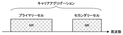
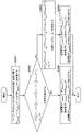
図1は、本実施形態におけるコンポーネントキャリアの設定の一例を示す図である。図1の例では、1つのLTEセルと2つのNRセルが設定される。1つのLTEセルは、プライマリーセルとして設定される。2つのNRセルは、それぞれプライマリーセカンダリーセルおよびセカンダリーセルとして設定される。2つのNRセルは、キャリアアグリゲーションにより統合される。また、LTEセルとNRセルは、デュアルコネクティビティにより統合される。なお、LTEセルとNRセルは、キャリアアグリゲーションにより統合されてもよい。図1の例では、NRは、プライマリーセルであるLTEセルにより接続をアシストされることが可能であるため、スタンドアロンで通信するための機能のような一部の機能をサポートしなくてもよい。スタンドアロンで通信するための機能は、初期接続に必要な機能を含む。 FIG. 1 is a diagram illustrating an example of component carrier settings in the present embodiment. In the example of FIG. 1, one LTE cell and two NR cells are set. One LTE cell is set as a primary cell. The two NR cells are set as a primary secondary cell and a secondary cell, respectively. The two NR cells are integrated by carrier aggregation. Further, the LTE cell and the NR cell are integrated by dual connectivity. Note that the LTE cell and the NR cell may be integrated by carrier aggregation. In the example of FIG. 1, since the NR can be assisted by the LTE cell that is the primary cell, the NR may not support some functions such as a function for performing stand-alone communication. The function for stand-alone communication includes a function necessary for initial connection.
図2は、本実施形態におけるコンポーネントキャリアの設定の一例を示す図である。図2の例では、2つのNRセルが設定される。2つのNRセルは、それぞれプライマリーセルおよびセカンダリーセルとして設定され、キャリアアグリゲーションにより統合される。この場合、NRセルがスタンドアロンで通信するための機能をサポートすることにより、LTEセルのアシストが不要になる。なお、2つのNRセルは、デュアルコネクティビティにより統合されてもよい。 FIG. 2 is a diagram illustrating an example of component carrier settings in the present embodiment. In the example of FIG. 2, two NR cells are set. The two NR cells are set as a primary cell and a secondary cell, respectively, and are integrated by carrier aggregation. In this case, the support of the LTE cell becomes unnecessary by supporting the function for the NR cell to perform stand-alone communication. Note that the two NR cells may be integrated by dual connectivity.
<1.2.無線フレーム構成>
<本実施形態における無線フレーム構成>
本実施形態において、10ms(ミリ秒)で構成される無線フレーム(radio frame)が規定される。無線フレームのそれぞれは2つのハーフフレームから構成される。ハーフフレームの時間間隔は、5msである。ハーフフレームのそれぞれは、5つのサブフレームから構成される。サブフレームの時間間隔は、1msであり、2つの連続するスロットによって定義される。スロットの時間間隔は、0.5msである。無線フレーム内のi番目のサブフレームは、(2×i)番目のスロットと(2×i+1)番目のスロットとから構成される。つまり、無線フレームのそれぞれにおいて、10個のサブフレームが規定される。
<1.2. Wireless frame configuration>
<Radio frame configuration in this embodiment>
In the present embodiment, a radio frame composed of 10 ms (milliseconds) is defined. Each radio frame is composed of two half frames. The time interval of the half frame is 5 ms. Each half frame is composed of five subframes. The subframe time interval is 1 ms and is defined by two consecutive slots. The slot time interval is 0.5 ms. The i-th subframe in the radio frame is composed of a (2 × i) th slot and a (2 × i + 1) th slot. That is, 10 subframes are defined in each radio frame.
サブフレームは、下りリンクサブフレーム、上りリンクサブフレーム、スペシャルサブフレームおよびサイドリンクサブフレームなどを含む。 The subframe includes a downlink subframe, an uplink subframe, a special subframe, a sidelink subframe, and the like.
下りリンクサブフレームは下りリンク送信のために予約されるサブフレームである。上りリンクサブフレームは上りリンク送信のために予約されるサブフレームである。スペシャルサブフレームは3つのフィールドから構成される。3つのフィールドは、DwPTS(Downlink Pilot Time Slot)、GP(Guard Period)、およびUpPTS(Uplink Pilot Time Slot)を含む。DwPTS、GP、およびUpPTSの合計の長さは1msである。DwPTSは下りリンク送信のために予約されるフィールドである。UpPTSは上りリンク送信のために予約されるフィールドである。GPは下りリンク送信および上りリンク送信が行われないフィールドである。なお、スペシャルサブフレームは、DwPTSおよびGPのみによって構成されてもよいし、GPおよびUpPTSのみによって構成されてもよい。スペシャルサブフレームは、TDDにおいて下りリンクサブフレームと上りリンクサブフレームとの間に配置され、下りリンクサブフレームから上りリンクサブフレームに切り替えるために用いられる。サイドリンクサブフレームは、サイドリンク通信のために予約または設定されるサブフレームである。サイドリンクは、端末装置間の近接直接通信および近接直接検出のために用いられる。 The downlink subframe is a subframe reserved for downlink transmission. An uplink subframe is a subframe reserved for uplink transmission. The special subframe is composed of three fields. The three fields include DwPTS (Downlink Pilot Time Slot), GP (Guard Period), and UpPTS (Uplink Pilot Time Slot). The total length of DwPTS, GP, and UpPTS is 1 ms. DwPTS is a field reserved for downlink transmission. UpPTS is a field reserved for uplink transmission. GP is a field in which downlink transmission and uplink transmission are not performed. Note that the special subframe may be configured only by DwPTS and GP, or may be configured only by GP and UpPTS. The special subframe is arranged between the downlink subframe and the uplink subframe in TDD, and is used for switching from the downlink subframe to the uplink subframe. The side link subframe is a subframe reserved or set for side link communication. The side link is used for proximity direct communication and proximity direct detection between terminal devices.
単一の無線フレームは、下りリンクサブフレーム、上りリンクサブフレーム、スペシャルサブフレームおよび/またはサイドリンクサブフレームから構成される。また、単一の無線フレームは、下りリンクサブフレーム、上りリンクサブフレーム、スペシャルサブフレームまたはサイドリンクサブフレームのみで構成されてもよい。 A single radio frame is composed of a downlink subframe, an uplink subframe, a special subframe, and / or a sidelink subframe. Also, a single radio frame may be composed of only downlink subframes, uplink subframes, special subframes, or sidelink subframes.
複数の無線フレーム構成がサポートされる。無線フレーム構成は、フレーム構成タイプで規定される。フレーム構成タイプ1は、FDDのみに適用できる。フレーム構成タイプ2は、TDDのみに適用できる。フレーム構成タイプ3は、LAA(Licensed Assisted Access)セカンダリーセルの運用のみに適用できる。
Multiple radio frame configurations are supported. The radio frame configuration is defined by the frame configuration type.
フレーム構成タイプ2において、複数の上りリンク−下りリンク構成が規定される。上りリンク−下りリンク構成において、1つの無線フレームにおける10のサブフレームのそれぞれは、下りリンクサブフレーム、上りリンクサブフレーム、およびスペシャルサブフレームのいずれかに対応する。サブフレーム0、サブフレーム5およびDwPTSは常に下りリンク送信のために予約される。UpPTSおよびそのスペシャルサブフレームの直後のサブフレームは常に上りリンク送信のために予約される。
In
フレーム構成タイプ3において、1つの無線フレーム内の10のサブフレームが下りリンク送信のために予約される。端末装置2は、PDSCHまたは検出信号が送信されないサブフレームを空のサブフレームとして扱うことができる。端末装置2は、所定の信号、チャネルおよび/または下りリンク送信があるサブフレームで検出されない限り、そのサブフレームにいかなる信号および/またはチャネルも存在しないと想定する。下りリンク送信は、1つまたは複数の連続したサブフレームで専有される。その下りリンク送信の最初のサブフレームは、そのサブフレーム内のどこからでも開始されてもよい。その下りリンク送信の最後のサブフレームは、完全に専有されるか、DwPTSで規定される時間間隔で専有されるか、のいずれかであってもよい。
In
なお、フレーム構成タイプ3において、1つの無線フレーム内の10のサブフレームが上りリンク送信のために予約されてもよい。また、1つの無線フレーム内の10のサブフレームのそれぞれが、下りリンクサブフレーム、上りリンクサブフレーム、スペシャルサブフレームおよびサイドリンクサブフレームのいずれかに対応するようにしてもよい。
In
基地局装置1は、スペシャルサブフレームのDwPTSにおいて、下りリンク物理チャネルおよび下りリンク物理信号を送信してもよい。基地局装置1は、スペシャルサブフレームのDwPTSにおいて、PBCH(Physical Broadcast Channel)の送信を制限できる。端末装置2は、スペシャルサブフレームのUpPTSにおいて、上りリンク物理チャネルおよび上りリンク物理信号を送信してもよい。端末装置2は、スペシャルサブフレームのUpPTSにおいて、一部の上りリンク物理チャネルおよび上りリンク物理信号の送信を制限できる。
The
なお、1つの送信における時間間隔はTTI(Transmission Time Interval)と呼称され、LTEにおいて、1ms(1サブフレーム)を1TTIと定義される。 Note that the time interval in one transmission is called TTI (Transmission Time Interval), and in LTE, 1 ms (1 subframe) is defined as 1 TTI.
<本実施形態におけるLTEのフレーム構成>
図3は、本実施形態におけるLTEの下りリンクサブフレームの一例を示す図である。図3に示される図は、LTEの下りリンクリソースグリッドとも呼称される。基地局装置1は、端末装置2への下りリンクサブフレームにおいて、LTEの下りリンク物理チャネルおよび/またはLTEの下りリンク物理信号を送信できる。端末装置2は、基地局装置1からの下りリンクサブフレームにおいて、LTEの下りリンク物理チャネルおよび/またはLTEの下りリンク物理信号を受信できる。
<LTE Frame Configuration in this Embodiment>
FIG. 3 is a diagram illustrating an example of an LTE downlink subframe in the present embodiment. The diagram shown in FIG. 3 is also referred to as an LTE downlink resource grid. The
図4は、本実施形態におけるLTEの上りリンクサブフレームの一例を示す図である。図4に示される図は、LTEの上りリンクリソースグリッドとも呼称される。端末装置2は、基地局装置1への上りリンクサブフレームにおいて、LTEの上りリンク物理チャネルおよび/またはLTEの上りリンク物理信号を送信できる。基地局装置1は、端末装置2からの上りリンクサブフレームにおいて、LTEの上りリンク物理チャネルおよび/またはLTEの上りリンク物理信号を受信できる。
FIG. 4 is a diagram illustrating an example of an LTE uplink subframe in the present embodiment. The diagram shown in FIG. 4 is also referred to as an LTE uplink resource grid. The
本実施形態において、LTEの物理リソースは以下のように定義されうる。1つのスロットは複数のシンボルによって定義される。スロットのそれぞれにおいて送信される物理信号または物理チャネルは、リソースグリッドによって表現される。下りリンクにおいて、リソースグリッドは、周波数方向に対する複数のサブキャリアと、時間方向に対する複数のOFDMシンボルによって定義される。上りリンクにおいて、リソースグリッドは、周波数方向に対する複数のサブキャリアと、時間方向に対する複数のSC−FDMAシンボルによって定義される。サブキャリアまたはリソースブロックの数は、セルの帯域幅に依存して決まるようにしてもよい。1つのスロットにおけるシンボルの数は、CP(Cyclic Prefix)のタイプによって決まる。CPのタイプは、ノーマルCPまたは拡張CPである。ノーマルCPにおいて、1つのスロットを構成するOFDMシンボルまたはSC−FDMAシンボルの数は7である。拡張CPにおいて、1つのスロットを構成するOFDMシンボルまたはSC−FDMAシンボルの数は6である。リソースグリッド内のエレメントのそれぞれはリソースエレメントと称される。リソースエレメントは、サブキャリアのインデックス(番号)とシンボルのインデックス(番号)とを用いて識別される。なお、本実施形態の説明において、OFDMシンボルまたはSC−FDMAシンボルは単にシンボルとも呼称される。 In the present embodiment, LTE physical resources can be defined as follows. One slot is defined by a plurality of symbols. The physical signal or physical channel transmitted in each of the slots is represented by a resource grid. In the downlink, the resource grid is defined by a plurality of subcarriers in the frequency direction and a plurality of OFDM symbols in the time direction. In the uplink, the resource grid is defined by a plurality of subcarriers in the frequency direction and a plurality of SC-FDMA symbols in the time direction. The number of subcarriers or resource blocks may be determined depending on the cell bandwidth. The number of symbols in one slot depends on the type of CP (Cyclic Prefix). The CP type is a normal CP or an extended CP. In the normal CP, the number of OFDM symbols or SC-FDMA symbols constituting one slot is seven. In the extended CP, the number of OFDM symbols or SC-FDMA symbols constituting one slot is six. Each element in the resource grid is called a resource element. The resource element is identified using a subcarrier index (number) and a symbol index (number). In the description of the present embodiment, the OFDM symbol or SC-FDMA symbol is also simply referred to as a symbol.
リソースブロックは、ある物理チャネル(PDSCHまたはPUSCHなど)をリソースエレメントにマッピングするために用いられる。リソースブロックは、仮想リソースブロックと物理リソースブロックを含む。ある物理チャネルは、仮想リソースブロックにマッピングされる。仮想リソースブロックは、物理リソースブロックにマッピングされる。1つの物理リソースブロックは、時間領域において所定数の連続するシンボルで定義される。1つの物理リソースブロックは、周波数領域において所定数の連続するサブキャリアとから定義される。1つの物理リソースブロックにおけるシンボル数およびサブキャリア数は、そのセルにおけるCPのタイプ、サブキャリア間隔および/または上位層によって設定されるパラメータなどに基づいて決まる。例えば、CPのタイプがノーマルCPであり、サブキャリア間隔が15kHzである場合、1つの物理リソースブロックにおけるシンボル数は7であり、サブキャリア数は12である。その場合、1つの物理リソースブロックは(7×12)個のリソースエレメントから構成される。物理リソースブロックは周波数領域において0から番号が付けられる。また、同一の物理リソースブロック番号が対応する、1つのサブフレーム内の2つのリソースブロックは、物理リソースブロックペア(PRBペア、RBペア)として定義される。 A resource block is used to map a certain physical channel (such as PDSCH or PUSCH) to a resource element. The resource block includes a virtual resource block and a physical resource block. A certain physical channel is mapped to a virtual resource block. A virtual resource block is mapped to a physical resource block. One physical resource block is defined by a predetermined number of consecutive symbols in the time domain. One physical resource block is defined from a predetermined number of consecutive subcarriers in the frequency domain. The number of symbols and the number of subcarriers in one physical resource block are determined based on the type of CP in the cell, the subcarrier spacing, and / or parameters set by higher layers. For example, when the CP type is normal CP and the subcarrier interval is 15 kHz, the number of symbols in one physical resource block is 7, and the number of subcarriers is 12. In that case, one physical resource block is composed of (7 × 12) resource elements. Physical resource blocks are numbered from 0 in the frequency domain. Further, two resource blocks in one subframe corresponding to the same physical resource block number are defined as physical resource block pairs (PRB pair, RB pair).
LTEセルのそれぞれにおいて、あるサブフレームでは、1つの所定のパラメータが用いられる。例えば、その所定のパラメータは、送信信号に関するパラメータ(物理パラメータ)である。送信信号に関するパラメータは、CP長、サブキャリア間隔、1つのサブフレーム(所定の時間長)におけるシンボル数、1つのリソースブロック(所定の周波数帯域)のおけるサブキャリア数、多元接続方式、および、信号波形などを含む。
すなわち、LTEセルでは、下りリンク信号および上りリンク信号は、それぞれ所定の時間長(例えば、サブフレーム)において、1つの所定のパラメータを用いて生成される。換言すると、端末装置2は、基地局装置1から送信される下りリンク信号、および、基地局装置1に送信する上りリンク信号が、それぞれ所定の時間長において、1つの所定のパラメータで生成される、と想定する。また、基地局装置1は、端末装置2に送信する下りリンク信号、および、端末装置2から送信される上りリンク信号が、それぞれ所定の時間長において、1つの所定のパラメータで生成されるように設定する。
In each LTE cell, one predetermined parameter is used in a certain subframe. For example, the predetermined parameter is a parameter (physical parameter) related to the transmission signal. Parameters related to the transmission signal include CP length, subcarrier interval, number of symbols in one subframe (predetermined time length), number of subcarriers in one resource block (predetermined frequency band), multiple access scheme, and signal Includes waveforms.
That is, in the LTE cell, the downlink signal and the uplink signal are generated using one predetermined parameter in each predetermined time length (for example, subframe). In other words, the
<本実施形態におけるNRのフレーム構成>
NRセルのそれぞれにおいて、ある所定の時間長(例えば、サブフレーム)では、1つ以上の所定のパラメータが用いられる。すなわち、NRセルでは、下りリンク信号および上りリンク信号は、それぞれ所定の時間長において、1つ以上の所定のパラメータを用いて生成される。換言すると、端末装置2は、基地局装置1から送信される下りリンク信号、および、基地局装置1に送信する上りリンク信号が、それぞれ所定の時間長において、1つ以上の所定のパラメータで生成される、と想定する。また、基地局装置1は、端末装置2に送信する下りリンク信号、および、端末装置2から送信される上りリンク信号が、それぞれ所定の時間長において、1つ以上の所定のパラメータで生成されるように設定できる。複数の所定のパラメータが用いられる場合、それらの所定のパラメータが用いられて生成される信号は、所定の方法により多重される。例えば、所定の方法は、FDM(Frequency Division Multiplexing)、TDM(Time Division Multiplexing)、CDM(Code Division Multiplexing)および/またはSDM(Spatial Division Multiplexing)などを含む。
<Frame structure of NR in this embodiment>
In each of the NR cells, one or more predetermined parameters are used in a certain predetermined time length (for example, subframe). That is, in the NR cell, the downlink signal and the uplink signal are each generated with one or more predetermined parameters in a predetermined time length. In other words, the
NRセルに設定される所定のパラメータの組み合わせは、パラメータセットとして、複数種類を予め規定できる。 A plurality of types of combinations of predetermined parameters set in the NR cell can be defined in advance as a parameter set.
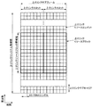
図5は、NRセルにおける送信信号に関するパラメータセットの一例を示す図である。図5の例では、パラメータセットに含まれる送信信号に関するパラメータは、サブキャリア間隔、NRセルにおけるリソースブロックあたりのサブキャリア数、サブフレームあたりのシンボル数、および、CP長タイプである。CP長タイプは、NRセルで用いられるCP長のタイプである。例えば、CP長タイプ1はLTEにおけるノーマルCPに相当し、CP長タイプ2はLTEにおける拡張CPに相当する。
FIG. 5 is a diagram illustrating an example of a parameter set regarding a transmission signal in the NR cell. In the example of FIG. 5, the parameters related to the transmission signal included in the parameter set are the subcarrier interval, the number of subcarriers per resource block in the NR cell, the number of symbols per subframe, and the CP length type. The CP length type is a CP length type used in the NR cell. For example,
NRセルにおける送信信号に関するパラメータセットは、下りリンクおよび上りリンクでそれぞれ個別に規定することができる。また、NRセルにおける送信信号に関するパラメータセットは、下りリンクおよび上りリンクでそれぞれ独立に設定できる。 Parameter sets related to transmission signals in the NR cell can be individually defined in the downlink and uplink. Also, parameter sets related to transmission signals in the NR cell can be set independently for the downlink and uplink.
図6は、本実施形態におけるNRの下りリンクサブフレームの一例を示す図である。図6の例では、パラメータセット1、パラメータセット0およびパラメータセット2を用いて生成される信号が、セル(システム帯域幅)において、FDMされる。図6に示される図は、NRの下りリンクリソースグリッドとも呼称される。基地局装置1は、端末装置2への下りリンクサブフレームにおいて、NRの下りリンク物理チャネルおよび/またはNRの下りリンク物理信号を送信できる。端末装置2は、基地局装置1からの下りリンクサブフレームにおいて、NRの下りリンク物理チャネルおよび/またはNRの下りリンク物理信号を受信できる。
FIG. 6 is a diagram illustrating an example of an NR downlink subframe in the present embodiment. In the example of FIG. 6, a signal generated using the parameter set 1, the parameter set 0, and the parameter set 2 is FDM in the cell (system bandwidth). The diagram shown in FIG. 6 is also referred to as the NR downlink resource grid. The
図7は、本実施形態におけるNRの上りリンクサブフレームの一例を示す図である。図7の例では、パラメータセット1、パラメータセット0およびパラメータセット2を用いて生成される信号が、セル(システム帯域幅)において、FDMされる。図6に示される図は、NRの上りリンクリソースグリッドとも呼称される。基地局装置1は、端末装置2への上りリンクサブフレームにおいて、NRの上りリンク物理チャネルおよび/またはNRの上りリンク物理信号を送信できる。端末装置2は、基地局装置1からの上りリンクサブフレームにおいて、NRの上りリンク物理チャネルおよび/またはNRの上りリンク物理信号を受信できる。
FIG. 7 is a diagram illustrating an example of an uplink subframe of NR in the present embodiment. In the example of FIG. 7, a signal generated using parameter set 1, parameter set 0, and parameter set 2 is FDM in a cell (system bandwidth). The diagram shown in FIG. 6 is also referred to as the NR uplink resource grid. The
このように、NRでは、サブキャリア間隔及びシンボル長を状況に応じて選択的に制御することが可能である(即ち、サブキャリア間隔及びシンボル長が可変である)。このような構成により、NRでは、例えば、所謂V2X(Vehicular−to−X(Something))と呼ばれる技術のように、信頼性が求められるような状況下においては、シンボル長を短くすることでより低遅延の通信を実現することも可能となる。 As described above, in the NR, the subcarrier interval and the symbol length can be selectively controlled according to the situation (that is, the subcarrier interval and the symbol length are variable). With such a configuration, in NR, for example, in a situation where reliability is required, such as a so-called V2X (Vehicular-to-X (Something)) technique, the symbol length can be shortened. It is also possible to realize low-latency communication.
<本実施形態におけるアンテナポート>
アンテナポートは、あるシンボルを運ぶ伝搬チャネルが、同一のアンテナポートにおける別のシンボルを運ぶ伝搬チャネルから推測できるようにするために定義される。例えば、同一のアンテナポートにおける異なる物理リソースは、同一の伝搬チャネルで送信されていると想定できる。すなわち、あるアンテナポートにおけるシンボルは、そのアンテナポートにおける参照信号により伝搬チャネルを推定し、復調することができる。また、アンテナポート毎に1つのリソースグリッドがある。アンテナポートは、参照信号によって定義される。また、それぞれの参照信号は、複数のアンテナポートを定義できる。
<Antenna port in this embodiment>
An antenna port is defined so that a propagation channel carrying one symbol can be inferred from a propagation channel carrying another symbol at the same antenna port. For example, it can be assumed that different physical resources in the same antenna port are transmitted on the same propagation channel. In other words, a symbol at a certain antenna port can be demodulated by estimating a propagation channel using a reference signal at that antenna port. There is one resource grid per antenna port. An antenna port is defined by a reference signal. Each reference signal can define a plurality of antenna ports.
アンテナポートはアンテナポート番号によって特定または識別される。例えば、アンテナポート0〜3は、CRSが送信されるアンテナポートである。すなわち、アンテナポート0〜3で送信されるPDSCHは、アンテナポート0〜3に対応するCRSで復調できる。
An antenna port is identified or identified by an antenna port number. For example,
2つのアンテナポートは所定の条件を満たす場合、準同一位置(QCL:Quasi co-location)であると表すことができる。その所定の条件は、あるアンテナポートにおけるシンボルを運ぶ伝搬チャネルの広域的特性が、別のアンテナポートにおけるシンボルを運ぶ伝搬チャネルから推測できることである。広域的特性は、遅延分散、ドップラースプレッド、ドップラーシフト、平均利得および/または平均遅延を含む。 When the two antenna ports satisfy a predetermined condition, they can be expressed as quasi-co-location (QCL). The predetermined condition is that the wide-area characteristics of a propagation channel carrying a symbol at one antenna port can be inferred from the propagation channel carrying a symbol at another antenna port. Global characteristics include delay dispersion, Doppler spread, Doppler shift, average gain and / or average delay.
本実施形態において、アンテナポート番号は、RAT毎に異なって定義されてもよいし、RAT間で共通に定義されてもよい。例えば、LTEにおけるアンテナポート0〜3は、CRSが送信されるアンテナポートである。NRにおいて、アンテナポート0〜3は、LTEと同様のCRSが送信されるアンテナポートとすることができる。また、NRにおいて、LTEと同様のCRSが送信されるアンテナポートは、アンテナポート0〜3とは異なるアンテナポート番号とすることができる。本実施形態の説明において、所定のアンテナポート番号は、LTEおよび/またはNRに対して適用できる。
In the present embodiment, the antenna port number may be defined differently for each RAT, or may be defined in common between RATs. For example,
<1.3.チャネルおよび信号>
<本実施形態における物理チャネルおよび物理信号>
本実施形態において、物理チャネルおよび物理信号が用いられる。物理チャネルは、下りリンク物理チャネル、上りリンク物理チャネルおよびサイドリンク物理チャネルを含む。物理信号は、下りリンク物理信号、上りリンク物理信号およびサイドリンク物理信号を含む。
<1.3. Channels and signals>
<Physical channel and physical signal in this embodiment>
In this embodiment, physical channels and physical signals are used. The physical channel includes a downlink physical channel, an uplink physical channel, and a side link physical channel. The physical signal includes a downlink physical signal, an uplink physical signal, and a side link physical signal.
LTEにおける物理チャネルおよび物理信号は、それぞれLTE物理チャネルおよびLTE物理信号とも呼称される。NRにおける物理チャネルおよび物理信号は、それぞれNR物理チャネルおよびNR物理信号とも呼称される。LTE物理チャネルおよびNR物理チャネルは、それぞれ異なる物理チャネルとして定義できる。LTE物理信号およびNR物理信号は、それぞれ異なる物理信号として定義できる。本実施形態の説明において、LTE物理チャネルおよびNR物理チャネルは単に物理チャネルとも呼称され、LTE物理信号およびNR物理信号は単に物理信号とも呼称される。すなわち、物理チャネルに対する説明は、LTE物理チャネルおよびNR物理チャネルのいずれに対しても適用できる。物理信号に対する説明は、LTE物理信号およびNR物理信号のいずれに対しても適用できる。 Physical channels and physical signals in LTE are also referred to as LTE physical channels and LTE physical signals, respectively. The physical channel and physical signal in NR are also referred to as NR physical channel and NR physical signal, respectively. The LTE physical channel and the NR physical channel can be defined as different physical channels. The LTE physical signal and the NR physical signal can be defined as different physical signals. In the description of this embodiment, the LTE physical channel and the NR physical channel are also simply referred to as physical channels, and the LTE physical signal and the NR physical signal are also simply referred to as physical signals. That is, the description for the physical channel can be applied to both the LTE physical channel and the NR physical channel. The description for the physical signal can be applied to both the LTE physical signal and the NR physical signal.
<本実施形態におけるNR物理チャネルおよびNR物理信号>
既に説明したように、物理チャネルおよび物理信号に対する説明は、それぞれNR物理チャネルおよびNR物理信号に対しても適用できる。NR物理チャネルおよびNR物理信号は、以下のように呼称される。
<NR physical channel and NR physical signal in this embodiment>
As already described, the description for the physical channel and the physical signal can be applied to the NR physical channel and the NR physical signal, respectively. The NR physical channel and the NR physical signal are referred to as follows.
NR下りリンク物理チャネルは、NR−PBCH、NR−PCFICH(Physical Control Format Indicator Channel)、NR−PHICH(Physical Hybrid automatic repeat request Indicator Channel)、NR−PDCCH(Physical Downlink Control Channel)、NR−EPDCCH(Enhanced PDCCH)、NR−MPDCCH(MTC PDCCH)、NR−R−PDCCH(Relay PDCCH)、NR−PDSCH(Physical Downlink Shared Channel)、および、NR−PMCH(Physical Multicast Channel)などを含む。 NR downlink physical channels are NR-PBCH, NR-PCFICH (Physical Control Format Indicator Channel), NR-PHICH (Physical Hybrid Automatic Repeat Request Indicator Channel), NR-PDCCH (Physical Downlink Control Channel), NR-EPDCCH (Enhanced PDCCH), NR-MPDCCH (MTC PDCCH), NR-R-PDCCH (Relay PDCCH), NR-PDSCH (Physical Downlink Shared Channel), NR-PMCH (Physical Multicast Channel), and the like.
NR下りリンク物理信号は、NR−SS(Synchronization signal)、NR−DL−RS(Downlink Reference Signal)およびNR−DS(Discovery signal)などを含む。NR−SSは、NR−PSS(Primary synchronization signal)およびNR−SSS(Secondary synchronization signal)などを含む。NR−RSは、NR−CRS(Cell-specific reference signal)、NR−PDSCH−DMRS(UE-specific reference signal associated with PDSCH)、NR−EPDCCH−DMRS(Demodulation reference signal associated with EPDCCH)、NR−PRS(Positioning Reference Signal)、NR−CSI−RS(Channel State Information - reference signal)、およびNR−TRS(Tracking reference signal)などを含む。 The NR downlink physical signal includes NR-SS (Synchronization signal), NR-DL-RS (Downlink Reference Signal), NR-DS (Discovery signal), and the like. NR-SS includes NR-PSS (Primary synchronization signal), NR-SSS (Secondary synchronization signal), and the like. NR-RS includes NR-CRS (Cell-specific reference signal), NR-PDSCH-DMRS (UE-specific reference signal associated with PDSCH), NR-EPDCCH-DMRS (Demodulation reference signal associated with EPDCCH), NR-PRS ( Positioning Reference Signal (NR-CSI-RS), and NR-TRS (Tracking Reference Signal).
NR上りリンク物理チャネルは、NR−PUSCH(Physical Uplink Shared Channel)、NR−PUCCH(Physical Uplink Control Channel)、およびNR−PRACH(Physical Random Access Channel)などを含む。 The NR uplink physical channel includes NR-PUSCH (Physical Uplink Shared Channel), NR-PUCCH (Physical Uplink Control Channel), NR-PRACH (Physical Random Access Channel), and the like.
NR上りリンク物理信号は、NR−UL−RS(Uplink Reference Signal)を含む。NR−UL−RSは、NR−UL−DMRS(Uplink demodulation signal)およびNR−SRS(Sounding reference signal)などを含む。 The NR uplink physical signal includes NR-UL-RS (Uplink Reference Signal). The NR-UL-RS includes an NR-UL-DMRS (Uplink demodulation signal), an NR-SRS (Sounding reference signal), and the like.
NRサイドリンク物理チャネルは、NR−PSBCH(Physical Sidelink Broadcast Channel)、NR−PSCCH(Physical Sidelink Control Channel)、NR−PSDCH(Physical Sidelink Discovery Channel)、およびNR−PSSCH(Physical Sidelink Shared Channel)などを含む。 NR side link physical channels include NR-PSBCH (Physical Sidelink Broadcast Channel), NR-PSCCH (Physical Sidelink Control Channel), NR-PSDCH (Physical Sidelink Discovery Channel), NR-PSSCH (Physical Sidelink Shared Channel), and the like. .
<本実施形態における下りリンク物理チャネル>
PBCHは、基地局装置1のサービングセルに固有の報知情報であるMIB(Master Information Block)を報知するために用いられる。PBCHは無線フレーム内のサブフレーム0のみで送信される。MIBは、40ms間隔で更新できる。PBCHは10ms周期で繰り返し送信される。具体的には、SFN(System Frame Number)を4で割った余りが0である条件を満たす無線フレームにおけるサブフレーム0においてMIBの初期送信が行なわれ、他の全ての無線フレームにおけるサブフレーム0においてMIBの再送信(repetition)が行われる。SFNは無線フレームの番号(システムフレーム番号)である。MIBはシステム情報である。例えば、MIBは、SFNを示す情報を含む。
<Downlink physical channel in this embodiment>
The PBCH is used to broadcast an MIB (Master Information Block) that is broadcast information unique to the serving cell of the
PCFICHは、PDCCHの送信に用いられるOFDMシンボルの数に関する情報を送信するために用いられる。PCFICHで示される領域は、PDCCH領域とも呼称される。PCFICHで送信される情報は、CFI(Control Format Indicator)とも呼称される。 PCFICH is used to transmit information regarding the number of OFDM symbols used for transmission of PDCCH. A region indicated by PCFICH is also referred to as a PDCCH region. Information transmitted by PCFICH is also referred to as CFI (Control Format Indicator).
PHICHは、基地局装置1が受信した上りリンクデータ(Uplink Shared Channel: UL-SCH)に対するACK(ACKnowledgement)またはNACK(Negative ACKnowledgement)を示すHARQ−ACK(HARQインディケータ、HARQフィードバック、応答情報、HARQ:Hybrid Automatic Repeat reQuest)を送信するために用いられる。例えば、端末装置2がACKを示すHARQ−ACKを受信した場合は、対応する上りリンクデータを再送しない。例えば、端末装置2がNACKを示すHARQ−ACKを受信した場合は、端末装置2は対応する上りリンクデータを所定の上りリンクサブフレームで再送する。あるPHICHは、ある上りリンクデータに対するHARQ−ACKを送信する。基地局装置1は、同一のPUSCHに含まれる複数の上りリンクデータに対するHARQ−ACKのそれぞれを複数のPHICHを用いて送信する。
The PHICH is a HARQ-ACK (HARQ indicator, HARQ feedback, response information, HARQ: indicating ACK (ACKnowledgement) or NACK (Negative ACKnowledgement) for uplink data (Uplink Shared Channel: UL-SCH) received by the
PDCCHおよびEPDCCHは、下りリンク制御情報(Downlink Control Information: DCI)を送信するために用いられる。下りリンク制御情報の情報ビットのマッピングが、DCIフォーマットとして定義される。下りリンク制御情報は、下りリンクグラント(downlink grant)および上りリンクグラント(uplink grant)を含む。下りリンクグラントは、下りリンクアサインメント(downlink assignment)または下りリンク割り当て(downlink allocation)とも称する。 PDCCH and EPDCCH are used for transmitting downlink control information (Downlink Control Information: DCI). Mapping of information bits of downlink control information is defined as a DCI format. The downlink control information includes a downlink grant (downlink grant) and an uplink grant (uplink grant). The downlink grant is also referred to as downlink assignment or downlink allocation.
PDCCHは、連続する1つまたは複数のCCE(Control Channel Element)の集合によって送信される。CCEは、9つのREG(Resource Element Group)で構成される。REGは、4つのリソースエレメントで構成される。PDCCHがn個の連続するCCEで構成される場合、そのPDCCHは、CCEのインデックス(番号)であるiをnで割った余りが0である条件を満たすCCEから始まる。 The PDCCH is transmitted by a set of one or more consecutive CCEs (Control Channel Elements). The CCE is composed of nine REGs (Resource Element Groups). The REG is composed of four resource elements. When the PDCCH is composed of n consecutive CCEs, the PDCCH starts with a CCE that satisfies the condition that a remainder obtained by dividing i, which is an index (number) of the CCE, by n is 0.
EPDCCHは、連続する1つまたは複数のECCE(Enhanced Control Channel Element)の集合によって送信される。ECCEは、複数のEREG(Enhanced Resource Element Group)で構成される。 The EPDCCH is transmitted by a set of one or a plurality of continuous enhanced control channel elements (ECCEs). The ECCE is composed of a plurality of EREG (Enhanced Resource Element Group).
下りリンクグラントは、あるセル内のPDSCHのスケジューリングに用いられる。下りリンクグラントは、その下りリンクグラントが送信されたサブフレームと同じサブフレーム内のPDSCHのスケジューリングに用いられる。上りリンクグラントは、あるセル内のPUSCHのスケジューリングに用いられる。上りリンクグラントは、その上りリンクグラントが送信されたサブフレームより4つ以上後のサブフレーム内の単一のPUSCHのスケジューリングに用いられる。 The downlink grant is used for scheduling of PDSCH in a certain cell. The downlink grant is used for scheduling the PDSCH in the same subframe as the subframe in which the downlink grant is transmitted. The uplink grant is used for scheduling the PUSCH in a certain cell. The uplink grant is used for scheduling a single PUSCH in a subframe that is four or more times after the subframe in which the uplink grant is transmitted.
DCIには、CRC(Cyclic Redundancy Check)パリティビットが付加される。CRCパリティビットは、RNTI(Radio Network Temporary Identifier)でスクランブルされる。RNTIは、DCIの目的などに応じて、規定または設定できる識別子である。RNTIは、仕様で予め規定される識別子、セルに固有の情報として設定される識別子、端末装置2に固有の情報として設定される識別子、または、端末装置2に属するグループに固有の情報として設定される識別子である。例えば、端末装置2は、PDCCHまたはEPDCCHのモニタリングにおいて、DCIに付加されたCRCパリティビットに所定のRNTIでデスクランブルし、CRCが正しいかどうかを識別する。CRCが正しい場合、そのDCIは端末装置2のためのDCIであることが分かる。
A CRC (Cyclic Redundancy Check) parity bit is added to the DCI. The CRC parity bit is scrambled with an RNTI (Radio Network Temporary Identifier). The RNTI is an identifier that can be defined or set according to the purpose of the DCI. The RNTI is set as an identifier preliminarily specified in the specification, an identifier set as information specific to a cell, an identifier set as information specific to the
PDSCHは、下りリンクデータ(Downlink Shared Channel: DL-SCH)を送信するために用いられる。また、PDSCHは、上位層の制御情報を送信するためにも用いられる。 The PDSCH is used to transmit downlink data (Downlink Shared Channel: DL-SCH). The PDSCH is also used for transmitting higher layer control information.
PMCHは、マルチキャストデータ(Multicast Channel: MCH)を送信するために用いられる。 The PMCH is used for transmitting multicast data (Multicast Channel: MCH).
PDCCH領域において、複数のPDCCHが周波数、時間、および/または、空間多重されてもよい。EPDCCH領域において、複数のEPDCCHが周波数、時間、および/または、空間多重されてもよい。PDSCH領域において、複数のPDSCHが周波数、時間、および/または、空間多重されてもよい。PDCCH、PDSCHおよび/またはEPDCCHは周波数、時間、および/または、空間多重されてもよい。 In the PDCCH region, a plurality of PDCCHs may be frequency, time, and / or spatially multiplexed. In the EPDCCH region, a plurality of EPDCCHs may be frequency, time and / or spatially multiplexed. In the PDSCH region, a plurality of PDSCHs may be frequency, time and / or spatially multiplexed. PDCCH, PDSCH and / or EPDCCH may be frequency, time and / or spatially multiplexed.
<本実施形態における下りリンク物理信号>
同期信号は、端末装置2が下りリンクの周波数領域および/または時間領域の同期をとるために用いられる。同期信号は、PSS(Primary Synchronization Signal)およびSSS(Secondary Synchronization Signal)を含む。同期信号は無線フレーム内の所定のサブフレームに配置される。例えば、TDD方式において、同期信号は無線フレーム内のサブフレーム0、1、5、および6に配置される。FDD方式において、同期信号は無線フレーム内のサブフレーム0および5に配置される。
<Downlink physical signal in this embodiment>
The synchronization signal is used for the
PSSは、粗いフレーム/シンボルタイミング同期(時間領域の同期)やセル識別グループの識別に用いられてもよい。SSSは、より正確なフレームタイミング同期やセルの識別、CP長の検出に用いられてもよい。つまり、PSSとSSSを用いることによって、フレームタイミング同期とセル識別を行うことができる。 The PSS may be used for coarse frame / symbol timing synchronization (time domain synchronization) and cell identification group identification. The SSS may be used for more accurate frame timing synchronization, cell identification, and CP length detection. That is, frame timing synchronization and cell identification can be performed by using PSS and SSS.
下りリンク参照信号は、端末装置2が下りリンク物理チャネルの伝搬路推定、伝搬路補正、下りリンクのCSI(Channel State Information、チャネル状態情報)の算出、および/または、端末装置2のポジショニングの測定を行うために用いられる。
For the downlink reference signal, the
CRSは、サブフレームの全帯域で送信される。CRSは、PBCH、PDCCH、PHICH、PCFICH、およびPDSCHの受信(復調)を行うために用いられる。CRSは、端末装置2が下りリンクのチャネル状態情報を算出するために用いられてもよい。PBCH、PDCCH、PHICH、およびPCFICHは、CRSの送信に用いられるアンテナポートで送信される。CRSは、1、2または4のアンテナポートの構成をサポートする。CRSは、アンテナポート0〜3の1つまたは複数で送信される。
The CRS is transmitted in the entire band of the subframe. CRS is used to receive (demodulate) PBCH, PDCCH, PHICH, PCFICH, and PDSCH. The CRS may be used for the
PDSCHに関連するURSは、URSが関連するPDSCHの送信に用いられるサブフレームおよび帯域で送信される。URSは、URSが関連するPDSCHの復調を行なうために用いられる。PDSCHに関連するURSは、アンテナポート5、7〜14の1つまたは複数で送信される。
The URS associated with the PDSCH is transmitted in subframes and bands used for transmission of the PDSCH associated with the URS. URS is used to demodulate the PDSCH with which the URS is associated. The URS associated with the PDSCH is transmitted on one or more of the
PDSCHは、送信モードおよびDCIフォーマットに基づいて、CRSまたはURSの送信に用いられるアンテナポートで送信される。DCIフォーマット1Aは、CRSの送信に用いられるアンテナポートで送信されるPDSCHのスケジューリングに用いられる。DCIフォーマット2Dは、URSの送信に用いられるアンテナポートで送信されるPDSCHのスケジューリングに用いられる。 The PDSCH is transmitted through an antenna port used for CRS or URS transmission based on the transmission mode and the DCI format. The DCI format 1A is used for scheduling of PDSCH transmitted through an antenna port used for CRS transmission. The DCI format 2D is used for scheduling of the PDSCH transmitted through the antenna port used for URS transmission.
EPDCCHに関連するDMRSは、DMRSが関連するEPDCCHの送信に用いられるサブフレームおよび帯域で送信される。DMRSは、DMRSが関連するEPDCCHの復調を行なうために用いられる。EPDCCHは、DMRSの送信に用いられるアンテナポートで送信される。EPDCCHに関連するDMRSは、アンテナポート107〜114の1つまたは複数で送信される。 The DMRS associated with the EPDCCH is transmitted in subframes and bands used for transmission of the EPDCCH associated with the DMRS. DMRS is used to demodulate the EPDCCH with which DMRS is associated. The EPDCCH is transmitted through an antenna port used for DMRS transmission. The DMRS associated with the EPDCCH is transmitted on one or more of the antenna ports 107-114.
CSI−RSは、設定されたサブフレームで送信される。CSI−RSが送信されるリソースは、基地局装置1によって設定される。CSI−RSは、端末装置2が下りリンクのチャネル状態情報を算出するために用いられる。端末装置2は、CSI−RSを用いて信号測定(チャネル測定)を行う。CSI−RSは、1、2、4、8、12、16、24および32の一部または全部のアンテナポートの設定をサポートする。CSI−RSは、アンテナポート15〜46の1つまたは複数で送信される。なお、サポートされるアンテナポートは、端末装置2の端末装置ケイパビリティ、RRCパラメータの設定、および/または設定される送信モードなどに基づいて決定されてもよい。
CSI-RS is transmitted in the set subframe. A resource for transmitting the CSI-RS is set by the
ZP CSI−RSのリソースは、上位層によって設定される。ZP CSI−RSのリソースはゼロ出力の電力で送信されてもよい。すなわち、ZP CSI−RSのリソースは何も送信しなくてもよい。ZP CSI−RSの設定したリソースにおいて、PDSCHおよびEPDCCHは送信されない。例えば、ZP CSI−RSのリソースは隣接セルがNZP CSI−RS(Non-Zero Power CSI-RS)の送信を行うために用いられる。また、例えば、ZP CSI−RS(Zero Power CSI-RS)のリソースはCSI−IM(Channel State Information − Interference Measurement)を測定するために用いられる。また、例えば、ZP CSI−RSのリソースはPDSCHなどの所定のチャネルが送信されないリソースである。換言すると、所定のチャネルは、ZP CSI−RSのリソースを除いて(レートマッチングして、パンクチャして)マッピングされる。 ZP CSI-RS resources are set by higher layers. ZP CSI-RS resources may be transmitted with zero output power. That is, no ZP CSI-RS resource need be transmitted. PDSCH and EPDCCH are not transmitted in the resource set by ZP CSI-RS. For example, ZP CSI-RS resources are used for neighboring cells to transmit NZP CSI-RS (Non-Zero Power CSI-RS). Further, for example, ZP CSI-RS (Zero Power CSI-RS) resources are used to measure CSI-IM (Channel State Information-Interference Measurement). Further, for example, the resource of ZP CSI-RS is a resource that does not transmit a predetermined channel such as PDSCH. In other words, a predetermined channel is mapped by excluding ZP CSI-RS resources (rate matching and puncturing).
<本実施形態における上りリンク物理チャネル>
PUCCHは、上りリンク制御情報(Uplink Control Information: UCI)を送信するために用いられる物理チャネルである。上りリンク制御情報は、下りリンクのチャネル状態情報(Channel State Information: CSI)、PUSCHリソースの要求を示すスケジューリング要求(Scheduling Request: SR)、下りリンクデータ(Transport block: TB, Downlink-Shared Channel: DL-SCH)に対するHARQ−ACKを含む。HARQ−ACKは、ACK/NACK、HARQフィードバック、または、応答情報とも称される。また、下りリンクデータに対するHARQ−ACKは、ACK、NACK、またはDTXを示す。
<Uplink physical channel in this embodiment>
The PUCCH is a physical channel used for transmitting uplink control information (UPCI). The uplink control information includes downlink channel state information (CSI), scheduling request (SR) indicating a request for PUSCH resources, downlink data (Transport block: TB, Downlink-Shared Channel: DL). -SCH) for HARQ-ACK. HARQ-ACK is also referred to as ACK / NACK, HARQ feedback, or response information. In addition, HARQ-ACK for downlink data indicates ACK, NACK, or DTX.
PUSCHは、上りリンクデータ(Uplink-Shared Channel: UL-SCH)を送信するために用いられる物理チャネルである。また、PUSCHは、上りリンクデータと共にHARQ−ACKおよび/またはチャネル状態情報を送信するために用いられてもよい。また、PUSCHは、チャネル状態情報のみ、または、HARQ−ACKおよびチャネル状態情報のみを送信するために用いられてもよい。 The PUSCH is a physical channel used for transmitting uplink data (Uplink-Shared Channel: UL-SCH). The PUSCH may also be used to transmit HARQ-ACK and / or channel state information along with uplink data. Moreover, PUSCH may be used to transmit only channel state information, or only HARQ-ACK and channel state information.
PRACHは、ランダムアクセスプリアンブルを送信するために用いられる物理チャネルである。PRACHは、端末装置2が基地局装置1と時間領域の同期をとるために用いられることができる。また、PRACHは、初期コネクション構築(initial connection establishment)手続き(処理)、ハンドオーバ手続き、コネクション再構築(connection re-establishment)手続き、上りリンク送信に対する同期(タイミング調整)、および/または、PUSCHリソースの要求を示すためにも用いられる。
PRACH is a physical channel used for transmitting a random access preamble. The PRACH can be used for the
PUCCH領域において、複数のPUCCHが周波数、時間、空間および/またはコード多重される。PUSCH領域において、複数のPUSCHが周波数、時間、空間および/またはコード多重されてもよい。PUCCHおよびPUSCHは周波数、時間、空間および/またはコード多重されてもよい。PRACHは単一のサブフレームまたは2つのサブフレームにわたって配置されてもよい。複数のPRACHが符号多重されてもよい。 In the PUCCH region, a plurality of PUCCHs are frequency, time, space and / or code multiplexed. In the PUSCH region, a plurality of PUSCHs may be frequency, time, space and / or code multiplexed. PUCCH and PUSCH may be frequency, time, space and / or code multiplexed. The PRACH may be arranged over a single subframe or two subframes. A plurality of PRACHs may be code-multiplexed.
<本実施形態における上りリンク物理信号>
UL−DMRSは、PUSCHまたはPUCCHの送信に関連する。UL−DMRSは、PUSCHまたはPUCCHと時間多重される。基地局装置1は、PUSCHまたはPUCCHの伝搬路補正を行うためにUL−DMRSを用いてもよい。本実施形態の説明において、PUSCHの送信は、PUSCHとUL−DMRSを多重して送信することも含む。本実施形態の説明において、PUCCHの送信は、PUCCHとUL−DMRSを多重して送信することも含む。
<Uplink physical signal in this embodiment>
UL-DMRS is related to transmission of PUSCH or PUCCH. UL-DMRS is time-multiplexed with PUSCH or PUCCH. The
SRSは、PUSCHまたはPUCCHの送信に関連しない。基地局装置1は、上りリンクのチャネル状態を測定するためにSRSを用いてもよい。
SRS is not related to PUSCH or PUCCH transmission. The
SRSは上りリンクサブフレーム内の最後のSC−FDMAシンボルを用いて送信される。つまり、SRSは上りリンクサブフレーム内の最後のSC−FDMAシンボルに配置される。端末装置2は、あるセルのあるSC−FDMAシンボルにおいて、SRSと、PUCCH、PUSCHおよび/またはPRACHとの同時送信を制限できる。端末装置2は、あるセルのある上りリンクサブフレームにおいて、その上りリンクサブフレーム内の最後のSC−FDMAシンボルを除くSC−FDMAシンボルを用いてPUSCHおよび/またはPUCCHを送信し、その上りリンクサブフレーム内の最後のSC−FDMAシンボルを用いてSRSを送信することができる。つまり、あるセルのある上りリンクサブフレームにおいて、端末装置2は、SRSと、PUSCHおよびPUCCHと、を送信することができる。
The SRS is transmitted using the last SC-FDMA symbol in the uplink subframe. That is, the SRS is arranged in the last SC-FDMA symbol in the uplink subframe. The
SRSにおいて、トリガータイプの異なるSRSとして、トリガータイプ0SRSおよびトリガータイプ1SRSが定義される。トリガータイプ0SRSは、上位層シグナリングによって、トリガータイプ0SRSに関するパラメータが設定される場合に送信される。トリガータイプ1SRSは、上位層シグナリングによって、トリガータイプ1SRSに関するパラメータが設定され、DCIフォーマット0、1A、2B、2C、2D、または4に含まれるSRSリクエストによって送信が要求された場合に送信される。なお、SRSリクエストは、DCIフォーマット0、1A、または4についてはFDDとTDDの両方に含まれ、DCIフォーマット2B、2C、または2DについてはTDDにのみ含まれる。同じサービングセルの同じサブフレームでトリガータイプ0SRSの送信とトリガータイプ1SRSの送信が生じる場合、トリガータイプ1SRSの送信が優先される。
In SRS,
<本実施形態における制御チャネルのための物理リソース>
リソースエレメントグループ(REG:Resource Element Group)は、リソースエレメントと制御チャネルのマッピングを定義するために用いられる。例えば、REGは、PDCCH、PHICH、またはPCFICHのマッピングに用いられる。REGは、同一のOFDMシンボル内であり、同一のリソースブロック内において、CRSのために用いられない4つの連続したリソースエレメントで構成される。また、REGは、あるサブフレーム内の1番目のスロットにおける1番目のOFDMシンボルから4番目のOFDMシンボルの中で構成される。
<Physical resource for control channel in this embodiment>
A resource element group (REG) is used to define a mapping between resource elements and control channels. For example, REG is used for mapping of PDCCH, PHICH, or PCFICH. The REG is composed of four consecutive resource elements that are not used for CRS in the same OFDM symbol and in the same resource block. The REG is configured from the first OFDM symbol to the fourth OFDM symbol in the first slot in a certain subframe.
拡張リソースエレメントグループ(EREG:Enhanced Resource Element Group)は、リソースエレメントと拡張制御チャネルのマッピングを定義するために用いられる。例えば、EREGは、EPDCCHのマッピングに用いられる。1つのリソースブロックペアは16のEREGで構成される。それぞれのEREGはリソースブロックペア毎に0から15の番号が付される。それぞれのEREGは、1つのリソースブロックペアにおいて、EPDCCHに関連付けられたDM−RSのために用いられるリソースエレメントを除いた9つのリソースエレメントで構成される。 An enhanced resource element group (EREG) is used to define the mapping between resource elements and enhanced control channels. For example, EREG is used for EPDCCH mapping. One resource block pair is composed of 16 EREGs. Each EREG is assigned a number from 0 to 15 for each resource block pair. Each EREG is composed of nine resource elements excluding resource elements used for DM-RS associated with EPDCCH in one resource block pair.
<1.4.構成>
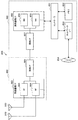
<本実施形態における基地局装置1の構成例>
図8は、本実施形態の基地局装置1の構成を示す概略ブロック図である。図示するように、基地局装置1は、上位層処理部101、制御部103、受信部105、送信部107、および、送受信アンテナ109、を含んで構成される。また、受信部105は、復号化部1051、復調部1053、多重分離部1055、無線受信部1057、およびチャネル測定部1059を含んで構成される。また、送信部107は、符号化部1071、変調部1073、多重部1075、無線送信部1077、および下りリンク参照信号生成部1079を含んで構成される。
<1.4. Configuration>
<Configuration example of
FIG. 8 is a schematic block diagram illustrating the configuration of the
既に説明したように、基地局装置1は、1つ以上のRATをサポートできる。図8に示す基地局装置1に含まれる各部の一部または全部は、RATに応じて個別に構成されうる。例えば、受信部105および送信部107は、LTEとNRとで個別に構成される。また、NRセルにおいて、図8に示す基地局装置1に含まれる各部の一部または全部は、送信信号に関するパラメータセットに応じて個別に構成されうる。例えば、あるNRセルにおいて、無線受信部1057および無線送信部1077は、送信信号に関するパラメータセットに応じて個別に構成されうる。
As already described, the
上位層処理部101は、媒体アクセス制御(MAC: Medium Access Control)層、パケットデータ統合プロトコル(Packet Data Convergence Protocol: PDCP)層、無線リンク制御(Radio Link Control: RLC)層、無線リソース制御(Radio Resource Control: RRC)層の処理を行う。また、上位層処理部101は、受信部105、および送信部107の制御を行うために制御情報を生成し、制御部103に出力する。
The upper
制御部103は、上位層処理部101からの制御情報に基づいて、受信部105および送信部107の制御を行う。制御部103は、上位層処理部101への制御情報を生成し、上位層処理部101に出力する。制御部103は、復号化部1051からの復号化された信号およびチャネル測定部1059からのチャネル推定結果を入力する。制御部103は、符号化する信号を符号化部1071へ出力する。また、制御部103は、基地局装置1の全体または一部を制御するために用いられる。
The
上位層処理部101は、RAT制御、無線リソース制御、サブフレーム設定、スケジューリング制御、および/または、CSI報告制御に関する処理および管理を行う。上位層処理部101における処理および管理は、端末装置毎、または基地局装置に接続している端末装置共通に行われる。上位層処理部101における処理および管理は、上位層処理部101のみで行われてもよいし、上位ノードまたは他の基地局装置から取得してもよい。また、上位層処理部101における処理および管理は、RATに応じて個別に行われてもよい。例えば、上位層処理部101は、LTEにおける処理および管理と、NRにおける処理および管理とを個別に行う。
The upper
上位層処理部101におけるRAT制御では、RATに関する管理が行われる。例えば、RAT制御では、LTEに関する管理および/またはNRに関する管理が行われる。NRに関する管理は、NRセルにおける送信信号に関するパラメータセットの設定および処理を含む。
In the RAT control in the upper
上位層処理部101における無線リソース制御では、下りリンクデータ(トランスポートブロック)、システムインフォメーション、RRCメッセージ(RRCパラメータ)、および/または、MAC制御エレメント(CE:Control Element)の生成および/または管理が行われる。
In radio resource control in the higher
上位層処理部101におけるサブフレーム設定では、サブフレーム設定、サブフレームパターン設定、上りリンク−下りリンク設定、上りリンク参照UL−DL設定、および/または、下りリンク参照UL−DL設定の管理が行われる。なお、上位層処理部101におけるサブフレーム設定は、基地局サブフレーム設定とも呼称される。また、上位層処理部101におけるサブフレーム設定は、上りリンクのトラフィック量および下りリンクのトラフィック量に基づいて決定できる。また、上位層処理部101におけるサブフレーム設定は、上位層処理部101におけるスケジューリング制御のスケジューリング結果に基づいて決定できる。
In the subframe setting in the higher
上位層処理部101におけるスケジューリング制御では、受信したチャネル状態情報およびチャネル測定部1059から入力された伝搬路の推定値やチャネルの品質などに基づいて、物理チャネルを割り当てる周波数およびサブフレーム、物理チャネルの符号化率および変調方式および送信電力などが決定される。例えば、制御部103は、上位層処理部101におけるスケジューリング制御のスケジューリング結果に基づいて、制御情報(DCIフォーマット)を生成する。
In the scheduling control in the upper
上位層処理部101におけるCSI報告制御では、端末装置2のCSI報告が制御される。例えば、端末装置2においてCSIを算出するために想定するためのCSI参照リソースに関する設定が制御される。
In the CSI report control in the upper
受信部105は、制御部103からの制御に従って、送受信アンテナ109を介して端末装置2から送信された信号を受信し、さらに分離、復調、復号などの受信処理を行い、受信処理された情報を制御部103に出力する。なお、受信部105における受信処理は、あらかじめ規定された設定、または基地局装置1が端末装置2に通知した設定に基づいて行われる。
The receiving
無線受信部1057は、送受信アンテナ109を介して受信された上りリンクの信号に対して、中間周波数への変換(ダウンコンバート)、不要な周波数成分の除去、信号レベルが適切に維持されるように増幅レベルの制御、受信された信号の同相成分および直交成分に基づく直交復調、アナログ信号からディジタル信号への変換、ガードインターバル(Guard Interval: GI)の除去、および/または、高速フーリエ変換(Fast Fourier Transform: FFT)による周波数領域信号の抽出を行う。
The
多重分離部1055は、無線受信部1057から入力された信号から、PUCCHまたはPUSCHなどの上りリンクチャネルおよび/または上りリンク参照信号を分離する。多重分離部1055は、上りリンク参照信号をチャネル測定部1059に出力する。多重分離部1055は、チャネル測定部1059から入力された伝搬路の推定値から、上りリンクチャネルに対する伝搬路の補償を行う。
The
復調部1053は、上りリンクチャネルの変調シンボルに対して、BPSK(Binary Phase Shift Keying)、QPSK(Quadrature Phase shift Keying)、16QAM(Quadrature Amplitude Modulation)、64QAM、256QAM等の変調方式を用いて受信信号の復調を行う。復調部1053は、MIMO多重された上りリンクチャネルの分離および復調を行う。
The
復号化部1051は、復調された上りリンクチャネルの符号化ビットに対して、復号処理を行う。復号された上りリンクデータおよび/または上りリンク制御情報は制御部103へ出力される。復号化部1051は、PUSCHに対しては、トランスポートブロック毎に復号処理を行う。
The
チャネル測定部1059は、多重分離部1055から入力された上りリンク参照信号から伝搬路の推定値および/またはチャネルの品質などを測定し、多重分離部1055および/または制御部103に出力する。例えば、チャネル測定部1059は、UL−DMRSを用いてPUCCHまたはPUSCHに対する伝搬路補償を行うための伝搬路の推定値を測定し、SRSを用いて上りリンクにおけるチャネルの品質を測定する。
送信部107は、制御部103からの制御に従って、上位層処理部101から入力された下りリンク制御情報および下りリンクデータに対して、符号化、変調および多重などの送信処理を行う。例えば、送信部107は、PHICH、PDCCH、EPDCCH、PDSCH、および下りリンク参照信号を生成および多重し、送信信号を生成する。なお、送信部107における送信処理は、あらかじめ規定された設定、基地局装置1が端末装置2に通知した設定、または、同一のサブフレームで送信されるPDCCHまたはEPDCCHを通じて通知される設定に基づいて行われる。
The
符号化部1071は、制御部103から入力されたHARQインディケータ(HARQ−ACK)、下りリンク制御情報、および下りリンクデータを、ブロック符号化、畳込み符号化、ターボ符号化等の所定の符号化方式を用いて符号化を行う。変調部1073は、符号化部1071から入力された符号化ビットをBPSK、QPSK、16QAM、64QAM、256QAM等の所定の変調方式で変調する。下りリンク参照信号生成部1079は、物理セル識別子(PCI:Physical cell identification)、端末装置2に設定されたRRCパラメータなどに基づいて、下りリンク参照信号を生成する。多重部1075は、各チャネルの変調シンボルと下りリンク参照信号を多重し、所定のリソースエレメントに配置する。
The
無線送信部1077は、多重部1075からの信号に対して、逆高速フーリエ変換(Inverse Fast Fourier Transform: IFFT)による時間領域の信号への変換、ガードインターバルの付加、ベースバンドのディジタル信号の生成、アナログ信号への変換、直交変調、中間周波数の信号から高周波数の信号への変換(アップコンバート: up convert)、余分な周波数成分の除去、電力の増幅などの処理を行い、送信信号を生成する。無線送信部1077が出力した送信信号は、送受信アンテナ109から送信される。
The
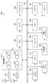
<本実施形態における端末装置2の構成例>
図9は、本実施形態の端末装置2の構成を示す概略ブロック図である。図示するように、端末装置2は、上位層処理部201、制御部203、受信部205、送信部207、および送受信アンテナ209を含んで構成される。また、受信部205は、復号化部2051、復調部2053、多重分離部2055、無線受信部2057、およびチャネル測定部2059を含んで構成される。また、送信部207は、符号化部2071、変調部2073、多重部2075、無線送信部2077、および上りリンク参照信号生成部2079を含んで構成される。
<Configuration Example of
FIG. 9 is a schematic block diagram showing the configuration of the
既に説明したように、端末装置2は、1つ以上のRATをサポートできる。図9に示す端末装置2に含まれる各部の一部または全部は、RATに応じて個別に構成されうる。例えば、受信部205および送信部207は、LTEとNRとで個別に構成される。また、NRセルにおいて、図9に示す端末装置2に含まれる各部の一部または全部は、送信信号に関するパラメータセットに応じて個別に構成されうる。例えば、あるNRセルにおいて、無線受信部2057および無線送信部2077は、送信信号に関するパラメータセットに応じて個別に構成されうる。
As already described, the
上位層処理部201は、上りリンクデータ(トランスポートブロック)を、制御部203に出力する。上位層処理部201は、媒体アクセス制御(MAC: Medium Access Control)層、パケットデータ統合プロトコル(Packet Data Convergence Protocol: PDCP)層、無線リンク制御(Radio Link Control: RLC)層、無線リソース制御(Radio Resource Control: RRC)層の処理を行なう。また、上位層処理部201は、受信部205、および送信部207の制御を行うために制御情報を生成し、制御部203に出力する。
The upper
制御部203は、上位層処理部201からの制御情報に基づいて、受信部205および送信部207の制御を行う。制御部203は、上位層処理部201への制御情報を生成し、上位層処理部201に出力する。制御部203は、復号化部2051からの復号化された信号およびチャネル測定部2059からのチャネル推定結果を入力する。制御部203は、符号化する信号を符号化部2071へ出力する。また、制御部203は、端末装置2の全体または一部を制御するために用いられてもよい。
The
上位層処理部201は、RAT制御、無線リソース制御、サブフレーム設定、スケジューリング制御、および/または、CSI報告制御に関する処理および管理を行う。上位層処理部201における処理および管理は、あらかじめ規定される設定、および/または、基地局装置1から設定または通知される制御情報に基づく設定に基づいて行われる。例えば、基地局装置1からの制御情報は、RRCパラメータ、MAC制御エレメントまたはDCIを含む。また、上位層処理部201における処理および管理は、RATに応じて個別に行われてもよい。例えば、上位層処理部201は、LTEにおける処理および管理と、NRにおける処理および管理とを個別に行う。
The upper
上位層処理部201におけるRAT制御では、RATに関する管理が行われる。例えば、RAT制御では、LTEに関する管理および/またはNRに関する管理が行われる。NRに関する管理は、NRセルにおける送信信号に関するパラメータセットの設定および処理を含む。
In the RAT control in the upper
上位層処理部201における無線リソース制御では、自装置における設定情報の管理が行われる。上位層処理部201における無線リソース制御では、上りリンクデータ(トランスポートブロック)、システムインフォメーション、RRCメッセージ(RRCパラメータ)、および/または、MAC制御エレメント(CE:Control Element)の生成および/または管理が行われる。
In the radio resource control in the upper
上位層処理部201におけるサブフレーム設定では、基地局装置1および/または基地局装置1とは異なる基地局装置におけるサブフレーム設定が管理される。サブフレーム設定は、サブフレームに対する上りリンクまたは下りリンクの設定、サブフレームパターン設定、上りリンク−下りリンク設定、上りリンク参照UL−DL設定、および/または、下りリンク参照UL−DL設定を含む。なお、上位層処理部201におけるサブフレーム設定は、端末サブフレーム設定とも呼称される。
In the subframe setting in the higher
上位層処理部201におけるスケジューリング制御では、基地局装置1からのDCI(スケジューリング情報)に基づいて、受信部205および送信部207に対するスケジューリングに関する制御を行うための制御情報が生成される。
In the scheduling control in the upper
上位層処理部201におけるCSI報告制御では、基地局装置1に対するCSIの報告に関する制御が行われる。例えば、CSI報告制御では、チャネル測定部2059でCSIを算出するために想定するためのCSI参照リソースに関する設定が制御される。CSI報告制御では、DCIおよび/またはRRCパラメータに基づいて、CSIを報告するために用いられるリソース(タイミング)を制御する。
In CSI report control in the higher
受信部205は、制御部203からの制御に従って、送受信アンテナ209を介して基地局装置1から送信された信号を受信し、さらに分離、復調、復号などの受信処理を行い、受信処理された情報を制御部203に出力する。なお、受信部205における受信処理は、あらかじめ規定された設定、または基地局装置1からの通知または設定に基づいて行われる。
The receiving
無線受信部2057は、送受信アンテナ209を介して受信された上りリンクの信号に対して、中間周波数への変換(ダウンコンバート)、不要な周波数成分の除去、信号レベルが適切に維持されるように増幅レベルの制御、受信された信号の同相成分および直交成分に基づく直交復調、アナログ信号からディジタル信号への変換、ガードインターバル(Guard Interval: GI)の除去、および/または、高速フーリエ変換(Fast Fourier Transform: FFT)による周波数領域の信号の抽出を行う。
The
多重分離部2055は、無線受信部2057から入力された信号から、PHICH、PDCCH、EPDCCHまたはPDSCHなどの下りリンクチャネル、下りリンク同期信号および/または下りリンク参照信号を分離する。多重分離部2055は、下りリンク参照信号をチャネル測定部2059に出力する。多重分離部2055は、チャネル測定部2059から入力された伝搬路の推定値から、下りリンクチャネルに対する伝搬路の補償を行う。
The
復調部2053は、下りリンクチャネルの変調シンボルに対して、BPSK、QPSK、16QAM、64QAM、256QAM等の変調方式を用いて受信信号の復調を行う。復調部2053は、MIMO多重された下りリンクチャネルの分離および復調を行う。
The
復号化部2051は、復調された下りリンクチャネルの符号化ビットに対して、復号処理を行う。復号された下りリンクデータおよび/または下りリンク制御情報は制御部203へ出力される。復号化部2051は、PDSCHに対しては、トランスポートブロック毎に復号処理を行う。
The
チャネル測定部2059は、多重分離部2055から入力された下りリンク参照信号から伝搬路の推定値および/またはチャネルの品質などを測定し、多重分離部2055および/または制御部203に出力する。チャネル測定部2059が測定に用いる下りリンク参照信号は、少なくともRRCパラメータによって設定される送信モードおよび/または他のRRCパラメータに基づいて決定されてもよい。例えば、DL−DMRSはPDSCHまたはEPDCCHに対する伝搬路補償を行うための伝搬路の推定値を測定する。CRSはPDCCHまたはPDSCHに対する伝搬路補償を行うための伝搬路の推定値、および/または、CSIを報告するための下りリンクにおけるチャネルを測定する。CSI−RSは、CSIを報告するための下りリンクにおけるチャネルを測定する。チャネル測定部2059は、CRS、CSI−RSまたは検出信号に基づいて、RSRP(Reference Signal Received Power)および/またはRSRQ(Reference Signal Received Quality)を算出し、上位層処理部201へ出力する。
送信部207は、制御部203からの制御に従って、上位層処理部201から入力された上りリンク制御情報および上りリンクデータに対して、符号化、変調および多重などの送信処理を行う。例えば、送信部207は、PUSCHまたはPUCCHなどの上りリンクチャネルおよび/または上りリンク参照信号を生成および多重し、送信信号を生成する。なお、送信部207における送信処理は、あらかじめ規定された設定、または、基地局装置1から設定または通知に基づいて行われる。
The
符号化部2071は、制御部203から入力されたHARQインディケータ(HARQ−ACK)、上りリンク制御情報、および上りリンクデータを、ブロック符号化、畳込み符号化、ターボ符号化等の所定の符号化方式を用いて符号化を行う。変調部2073は、符号化部2071から入力された符号化ビットをBPSK、QPSK、16QAM、64QAM、256QAM等の所定の変調方式で変調する。上りリンク参照信号生成部2079は、端末装置2に設定されたRRCパラメータなどに基づいて、上りリンク参照信号を生成する。多重部2075は、各チャネルの変調シンボルと上りリンク参照信号を多重し、所定のリソースエレメントに配置する。
The
無線送信部2077は、多重部2075からの信号に対して、逆高速フーリエ変換(Inverse Fast Fourier Transform: IFFT)による時間領域の信号への変換、ガードインターバルの付加、ベースバンドのディジタル信号の生成、アナログ信号への変換、直交変調、中間周波数の信号から高周波数の信号への変換(アップコンバート: up convert)、余分な周波数成分の除去、電力の増幅などの処理を行い、送信信号を生成する。無線送信部2077が出力した送信信号は、送受信アンテナ209から送信される。
The
<1.5.制御情報および制御チャネル>
<本実施形態における制御情報のシグナリング>
基地局装置1および端末装置2は、それぞれ制御情報のシグナリング(通知、報知、設定)のために、様々な方法を用いることができる。制御情報のシグナリングは、様々な層(レイヤー)で行うことができる。制御情報のシグナリングは、物理層(レイヤー)を通じたシグナリングである物理層シグナリング、RRC層を通じたシグナリングであるRRCシグナリング、および、MAC層を通じたシグナリングであるMACシグナリングなどを含む。RRCシグナリングは、端末装置2に固有の制御情報を通知する専用のRRCシグナリング(Dedicated RRC signaling)、または、基地局装置1に固有の制御情報を通知する共通のRRCシグナリング(Common RRC signaling)である。RRCシグナリングやMACシグナリングなど、物理層から見て上位の層が用いるシグナリングは上位層シグナリングとも呼称される。
<1.5. Control information and control channel>
<Signaling of control information in this embodiment>
The
RRCシグナリングは、RRCパラメータをシグナリングすることにより実現される。MACシグナリングは、MAC制御エレメントをシグナリングすることにより実現される。物理層シグナリングは、下りリンク制御情報(DCI:Downlink Control Information)または上りリンクリンク制御情報(UCI:Uplink Control Information)をシグナリングすることにより実現される。RRCパラメータおよびMAC制御エレメントは、PDSCHまたはPUSCHを用いて送信される。DCIは、PDCCHまたはEPDCCHを用いて送信される。UCIは、PUCCHまたはPUSCHを用いて送信される。RRCシグナリングおよびMACシグナリングは、準静的(semi-static)な制御情報をシグナリングするために用いられ、準静的シグナリングとも呼称される。物理層シグナリングは、動的(dynamic)な制御情報をシグナリングするために用いられ、動的シグナリングとも呼称される。DCIは、PDSCHのスケジューリングまたはPUSCHのスケジューリングなどのために用いられる。UCIは、CSI報告、HARQ−ACK報告、および/またはスケジューリング要求(SR:Scheduling Request)などのために用いられる。 RRC signaling is realized by signaling RRC parameters. MAC signaling is realized by signaling a MAC control element. Physical layer signaling is realized by signaling downlink control information (DCI) or uplink control information (UCI). The RRC parameter and the MAC control element are transmitted using PDSCH or PUSCH. DCI is transmitted using PDCCH or EPDCCH. UCI is transmitted using PUCCH or PUSCH. RRC signaling and MAC signaling are used for signaling semi-static control information and are also referred to as semi-static signaling. Physical layer signaling is used to signal dynamic control information and is also referred to as dynamic signaling. DCI is used for PDSCH scheduling or PUSCH scheduling. UCI is used for CSI reporting, HARQ-ACK reporting, and / or scheduling request (SR).
<本実施形態における下りリンク制御情報の詳細>
DCIはあらかじめ規定されるフィールドを有するDCIフォーマットを用いて通知される。DCIフォーマットに規定されるフィールドは、所定の情報ビットがマッピングされる。DCIは、下りリンクスケジューリング情報、上りリンクスケジューリング情報、サイドリンクスケジューリング情報、非周期的CSI報告の要求、または、上りリンク送信電力コマンドを通知する。
<Details of downlink control information in this embodiment>
The DCI is notified using a DCI format having a predefined field. In the field defined in the DCI format, predetermined information bits are mapped. DCI notifies downlink scheduling information, uplink scheduling information, side link scheduling information, aperiodic CSI report request, or uplink transmission power command.
端末装置2がモニタするDCIフォーマットは、サービングセル毎に設定された送信モードによって決まる。すなわち、端末装置2がモニタするDCIフォーマットの一部は、送信モードによって異なることができる。例えば、下りリンク送信モード1が設定された端末装置2は、DCIフォーマット1AとDCIフォーマット1をモニタする。例えば、下りリンク送信モード4が設定された端末装置2は、DCIフォーマット1AとDCIフォーマット2をモニタする。例えば、上りリンク送信モード1が設定された端末装置2は、DCIフォーマット0をモニタする。例えば、上りリンク送信モード2が設定された端末装置2は、DCIフォーマット0とDCIフォーマット4をモニタする。
The DCI format monitored by the
端末装置2に対するDCIを通知するPDCCHが配置される制御領域は通知されず、端末装置2は端末装置2に対するDCIをブラインドデコーディング(ブラインド検出)により検出する。具体的には、端末装置2は、サービングセルにおいて、PDCCH候補のセットをモニタする。モニタリングは、そのセットの中のPDCCHのそれぞれに対して、全てのモニタされるDCIフォーマットによって復号を試みることを意味する。例えば、端末装置2は、端末装置2宛に送信される可能性がある全てのアグリゲーションレベル、PDCCH候補、および、DCIフォーマットについてデコードを試みる。端末装置2は、デコード(検出)が成功したDCI(PDCCH)を端末装置2に対するDCI(PDCCH)として認識する。
The control region in which the PDCCH for notifying the DCI for the
DCIに対して、巡回冗長検査(CRC: Cyclic Redundancy Check)が付加される。CRCは、DCIのエラー検出およびDCIのブラインド検出のために用いられる。CRC(CRCパリティビット)は、RNTI(Radio Network Temporary Identifier)によってスクランブルされる。端末装置2は、RNTIに基づいて、端末装置2に対するDCIかどうかを検出する。具体的には、端末装置2は、CRCに対応するビットに対して、所定のRNTIでデスクランブルを行い、CRCを抽出し、対応するDCIが正しいかどうかを検出する。
A cyclic redundancy check (CRC) is added to the DCI. The CRC is used for DCI error detection and DCI blind detection. CRC (CRC parity bit) is scrambled by RNTI (Radio Network Temporary Identifier). The
RNTIは、DCIの目的や用途に応じて規定または設定される。RNTIは、C−RNTI(Cell-RNTI)、SPS C−RNTI(Semi Persistent Scheduling C-RNTI)、SI−RNTI(System Information-RNTI)、P−RNTI(Paging-RNTI)、RA−RNTI(Random Access-RNTI)、TPC−PUCCH−RNTI(Transmit Power Control-PUCCH-RNTI)、TPC−PUSCH−RNTI(Transmit Power Control-PUSCH-RNTI)、一時的C−RNTI、M−RNTI(MBMS (Multimedia Broadcast Multicast Services) -RNTI)、および、eIMTA−RNTI、CC−RNTIを含む。 The RNTI is defined or set according to the purpose and application of the DCI. RNTI includes C-RNTI (Cell-RNTI), SPS C-RNTI (Semi Persistent Scheduling C-RNTI), SI-RNTI (System Information-RNTI), P-RNTI (Paging-RNTI), RA-RNTI (Random Access). -RNTI), TPC-PUCCH-RNTI (Transmit Power Control-PUCCH-RNTI), TPC-PUSCH-RNTI (Transmit Power Control-PUSCH-RNTI), Temporary C-RNTI, M-RNTI (MBMS (Multimedia Broadcast Multicast Services) -RNTI), eIMTA-RNTI, CC-RNTI.
C−RNTIおよびSPS C−RNTIは、基地局装置1(セル)内において端末装置2に固有のRNTIであり、端末装置2を識別するための識別子である。C−RNTIは、あるサブフレームにおけるPDSCHまたはPUSCHをスケジューリングするために用いられる。SPS C−RNTIは、PDSCHまたはPUSCHのためのリソースの周期的なスケジューリングをアクティベーションまたはリリースするために用いられる。SI−RNTIでスクランブルされたCRCを有する制御チャネルは、SIB(System Information Block)をスケジューリングするために用いられる。P−RNTIでスクランブルされたCRCを有する制御チャネルは、ページングを制御するために用いられる。RA−RNTIでスクランブルされたCRCを有する制御チャネルは、RACHに対するレスポンスをスケジューリングするために用いられる。TPC−PUCCH−RNTIでスクランブルされたCRCを有する制御チャネルは、PUCCHの電力制御を行うために用いられる。TPC−PUSCH−RNTIでスクランブルされたCRCを有する制御チャネルは、PUSCHの電力制御を行うために用いられる。Temporary C−RNTIでスクランブルされたCRCを有する制御チャネルは、C−RNTIが設定または認識されていない移動局装置によって用いられる。M−RNTIでスクランブルされたCRCを有する制御チャネルは、MBMSをスケジューリングするために用いられる。eIMTA−RNTIでスクランブルされたCRCを有する制御チャネルは、動的TDD(eIMTA)において、TDDサービングセルのTDD UL/DL設定に関する情報を通知するために用いられる。CC−RNTIでスクランブルされたCRCを有する制御チャネル(DCI)は、LAAセカンダリーセルにおいて、専有OFDMシンボルの設定を通知するために用いられる。なお、上記のRNTIに限らず、新たなRNTIによってDCIフォーマットがスクランブルされてもよい。
C-RNTI and SPS C-RNTI are RNTIs specific to the
スケジューリング情報(下りリンクスケジューリング情報、上りリンクスケジューリング情報、サイドリンクスケジューリング情報)は、周波数領域のスケジューリングとして、リソースブロックまたはリソースブロックグループを単位にスケジューリングを行うための情報を含む。リソースブロックグループは、連続するリソースブロックのセットであり、スケジューリングされる端末装置に対する割り当てられるリソースを示す。リソースブロックグループのサイズは、システム帯域幅に応じて決まる。 Scheduling information (downlink scheduling information, uplink scheduling information, side link scheduling information) includes information for performing scheduling in units of resource blocks or resource block groups as frequency domain scheduling. The resource block group is a set of consecutive resource blocks, and indicates resources allocated to terminal devices to be scheduled. The size of the resource block group is determined according to the system bandwidth.
<本実施形態における下りリンク制御チャネルの詳細>
DCIはPDCCHまたはEPDCCHなどの制御チャネルを用いて送信される。端末装置2は、RRCシグナリングによって設定された1つまたは複数のアクティベートされたサービングセルのPDCCH候補のセットおよび/またはEPDCCH候補のセットをモニタする。ここで、モニタリングとは、全てのモニタされるDCIフォーマットに対応するセット内のPDCCHおよび/またはEPDCCHのデコードを試みることである。
<Details of Downlink Control Channel in this Embodiment>
DCI is transmitted using a control channel such as PDCCH or EPDCCH. The
PDCCH候補のセットまたはEPDCCH候補のセットは、サーチスペースとも呼称される。サーチスペースには、共有サーチスペース(CSS)と端末固有サーチスペース(USS)が定義される。CSSは、PDCCHに関するサーチスペースのみに対して定義されてもよい。 A set of PDCCH candidates or a set of EPDCCH candidates is also referred to as a search space. In the search space, a shared search space (CSS) and a terminal-specific search space (USS) are defined. The CSS may be defined only for the search space for PDCCH.
CSS(Common Search Space)は、基地局装置1に固有のパラメータおよび/または予め規定されたパラメータに基づいて設定されるサーチスペースである。例えば、CSSは、複数の端末装置で共通に用いられるサーチスペースである。そのため、基地局装置1が複数の端末装置で共通の制御チャネルをCSSにマッピングすることにより、制御チャネルを送信するためのリソースが低減される。
CSS (Common Search Space) is a search space set based on parameters unique to the
USS(UE-specific Search Space)は、少なくとも端末装置2に固有のパラメータを用いて設定されるサーチスペースである。そのため、USSは、端末装置2に固有のサーチスペースであり、基地局装置1はUSSによって端末装置2に固有の制御チャネルを個別に送信することができる。そのため、基地局装置1は複数の端末装置に固有の制御チャネルを効率的にマッピングできる。
The USS (UE-specific Search Space) is a search space set using at least parameters specific to the
USSは、複数の端末装置に共通に用いられるように設定されてもよい。複数の端末装置に対して共通のUSSが設定されるために、端末装置2に固有のパラメータは、複数の端末装置の間で同じ値になるように設定される。例えば、複数の端末装置の間で同じパラメータに設定される単位は、セル、送信点、または所定の端末装置のグループなどである。
The USS may be set so as to be commonly used by a plurality of terminal devices. Since a common USS is set for a plurality of terminal devices, parameters unique to the
アグリゲーションレベル毎のサーチスペースはPDCCH候補のセットによって定義される。PDCCHのそれぞれは、1つ以上のCCE(Control Channel Element)の集合を用いて送信される。1つのPDCCHに用いられるCCEの数は、アグリゲーションレベルとも呼称される。例えば、1つのPDCCHに用いられるCCEの数は、1、2、4または8である。 The search space for each aggregation level is defined by a set of PDCCH candidates. Each PDCCH is transmitted using a set of one or more CCEs (Control Channel Elements). The number of CCEs used for one PDCCH is also referred to as an aggregation level. For example, the number of CCEs used for one PDCCH is 1, 2, 4 or 8.
アグリゲーションレベル毎のサーチスペースはEPDCCH候補のセットによって定義される。EPDCCHのそれぞれは、1つ以上のECCE(Enhanced Control Channel Element)の集合を用いて送信される。1つのEPDCCHに用いられるECCEの数は、アグリゲーションレベルとも呼称される。例えば、1つのEPDCCHに用いられるECCEの数は、1、2、4、8、16または32である。 The search space for each aggregation level is defined by a set of EPDCCH candidates. Each of the EPDCCHs is transmitted using a set of one or more ECCEs (Enhanced Control Channel Elements). The number of ECCEs used for one EPDCCH is also referred to as an aggregation level. For example, the number of ECCEs used for one EPDCCH is 1, 2, 4, 8, 16, or 32.
PDCCH候補の数またはEPDCCH候補の数は、少なくともサーチスペースおよびアグリゲーションレベルに基づいて決まる。例えば、CSSにおいて、アグリゲーションレベル4および8におけるPDCCH候補の数はそれぞれ4および2である。例えば、USSにおいて、アグリゲーション1、2、4および8におけるPDCCH候補の数はそれぞれ6、6、2および2である。
The number of PDCCH candidates or the number of EPDCCH candidates is determined based on at least the search space and the aggregation level. For example, in CSS, the number of PDCCH candidates at
それぞれのECCEは、複数のEREG(Enhanced resource element group)で構成される。EREGは、EPDCCHのリソースエレメントに対するマッピングを定義するために用いられる。各RBペアにおいて、0から15に番号付けされる、16個のEREGが定義される。すなわち、各RBペアにおいて、EREG0〜EREG15が定義される。各RBペアにおいて、EREG0〜EREG15は、所定の信号および/またはチャネルがマッピングされるリソースエレメント以外のリソースエレメントに対して、周波数方向を優先して、周期的に定義される。例えば、アンテナポート107〜110で送信されるEPDCCHに関連付けられる復調用参照信号がマッピングされるリソースエレメントは、EREGとして定義されない。
Each ECCE is composed of a plurality of EREG (Enhanced resource element group). EREG is used to define the mapping of EPDCCH to resource elements. In each RB pair, 16 EREGs, numbered from 0 to 15, are defined. That is, EREG0 to EREG15 are defined in each RB pair. In each RB pair, EREG0 to EREG15 are periodically defined by giving priority to the frequency direction with respect to resource elements other than resource elements to which a predetermined signal and / or channel is mapped. For example, the resource element to which the demodulation reference signal associated with the EPDCCH transmitted through the
1つのEPDCCHに用いられるECCEの数は、EPDCCHフォーマットに依存し、他のパラメータに基づいて決定される。1つのEPDCCHに用いられるECCEの数は、アグリゲーションレベルとも呼称される。例えば、1つのEPDCCHに用いられるECCEの数は、1つのRBペアにおけるEPDCCH送信に用いることができるリソースエレメントの数、EPDCCHの送信方法などに基づいて、決定される。例えば、1つのEPDCCHに用いられるECCEの数は、1、2、4、8、16または32である。また、1つのECCEに用いられるEREGの数は、サブフレームの種類およびサイクリックプレフィックスの種類に基づいて決定され、4または8である。EPDCCHの送信方法として、分散送信(Distributed transmission)および局所送信(Localized transmission)がサポートされる。 The number of ECCEs used for one EPDCCH depends on the EPDCCH format and is determined based on other parameters. The number of ECCEs used for one EPDCCH is also referred to as an aggregation level. For example, the number of ECCEs used for one EPDCCH is determined based on the number of resource elements that can be used for EPDCCH transmission in one RB pair, the EPDCCH transmission method, and the like. For example, the number of ECCEs used for one EPDCCH is 1, 2, 4, 8, 16, or 32. The number of EREGs used for one ECCE is determined based on the type of subframe and the type of cyclic prefix, and is 4 or 8. As transmission methods of EPDCCH, distributed transmission and localized transmission are supported.
EPDCCHは、分散送信または局所送信を用いることができる。分散送信および局所送信は、EREGおよびRBペアに対するECCEのマッピングが異なる。例えば、分散送信において、1つのECCEは、複数のRBペアのEREGを用いて構成される。局所送信において、1つのECCEは、1つのRBペアのEREGを用いて構成される。 The EPDCCH can use distributed transmission or local transmission. Distributed transmission and local transmission differ in the mapping of ECCE to EREG and RB pairs. For example, in distributed transmission, one ECCE is configured using EREGs of a plurality of RB pairs. In local transmission, one ECCE is configured using one RB pair of EREGs.
基地局装置1は、端末装置2に対して、EPDCCHに関する設定を行う。端末装置2は、基地局装置1からの設定に基づいて、複数のEPDCCHをモニタリングする。端末装置2がEPDCCHをモニタリングするRBペアのセットが、設定されうる。そのRBペアのセットは、EPDCCHセットまたはEPDCCH−PRBセットとも呼称される。1つの端末装置2に対して、1つ以上のEPDCCHセットが設定できる。各EPDCCHセットは、1つ以上のRBペアで構成される。また、EPDCCHに関する設定は、EPDCCHセット毎に個別に行うことができる。
The
基地局装置1は、端末装置2に対して、所定数のEPDCCHセットを設定できる。例えば、2つまでのEPDCCHセットが、EPDCCHセット0および/またはEPDCCHセット1として、設定できる。EPDCCHセットのそれぞれは、所定数のRBペアで構成できる。各EPDCCHセットは、複数のECCEの1つのセットを構成する。1つのEPDCCHセットに構成されるECCEの数は、そのEPDCCHセットとして設定されるRBペアの数、および、1つのECCEに用いられるEREGの数に基づいて、決定される。1つのEPDCCHセットに構成されるECCEの数がNである場合、各EPDCCHセットは、0〜N−1で番号付けされたECCEを構成する。例えば、1つのECCEに用いられるEREGの数が4である場合、4つのRBペアで構成されるEPDCCHセットは16個のECCEを構成する。
The
<1.6.技術的特徴>
<本実施形態におけるCA及びDCの詳細>
端末装置2は複数のセルが設定され、マルチキャリア送信を行うことができる。端末装置2が複数のセルを用いる通信は、CA(キャリアアグリゲーション)またはDC(デュアルコネクティビティ)と称される。本実施形態に記載の内容は、端末装置2に対して設定される複数のセルのそれぞれまたは一部に適用できる。端末装置2に設定されるセルを、サービングセルとも称する。サービングセルは、端末装置2との通信が確立し、データの送受信が可能であるセルとも言える。
<1.6. Technical features>
<Details of CA and DC in this embodiment>
The
CAおよびDCは、物理層の観点では、2つ以上の異なる周波数帯のセルを用いて通信が行われる。CAおよびDCをサポートする端末装置2は、2つ以上のセルからの信号を同時に受信する機能、または、2つ以上のセルへの信号を同時に送信する機能を備える。
CAおいて、設定される複数のサービングセルは、1つのプライマリーセル(PCell: Primary Cell)と1つ以上のセカンダリーセル(SCell: Secondary Cell)とを含む。CAをサポートしている端末装置2に対して、1つのプライマリーセルと1つ以上のセカンダリーセルが設定されうる。サービングセルは、プライマリーセルまたはセカンダリーセルである。
CA and DC communicate using cells of two or more different frequency bands from the viewpoint of the physical layer. The
In CA, a plurality of serving cells to be set includes one primary cell (PCell: Primary Cell) and one or more secondary cells (SCell: Secondary Cell). One primary cell and one or more secondary cells may be set for the
CAにおいて、設定される複数のサービングセルは、時間的に同期される。そのため、設定される複数のサービングセルのサブフレームの境界は、揃っている。CAにおいて、複数のサービングセルは、異なるサービングセル間の受信タイミング差がMACに影響を及ぼさないように、時間同期される。 In CA, a plurality of configured serving cells are synchronized in time. Therefore, the boundaries of the subframes of the plurality of serving cells to be set are aligned. In CA, multiple serving cells are time-synchronized so that reception timing differences between different serving cells do not affect the MAC.
プライマリーセルは、初期コネクション構築(initial connection establishment)手続きが行なわれたサービングセル、コネクション再構築(connection re-establishment)手続きを開始したサービングセル、または、ハンドオーバ手続きにおいてプライマリーセルと指示されたセルである。プライマリーセルは、プライマリー周波数でオペレーションする。セカンダリーセルは、コネクションの構築または再構築以降に設定されうる。セカンダリーセルは、セカンダリー周波数でオペレーションする。なお、コネクションは、RRCコネクションとも称される。 The primary cell is a serving cell in which an initial connection establishment procedure has been performed, a serving cell that has started a connection re-establishment procedure, or a cell designated as a primary cell in a handover procedure. The primary cell operates at the primary frequency. The secondary cell can be set after the connection is established or reconstructed. The secondary cell operates at the secondary frequency. The connection is also referred to as an RRC connection.
DCは、少なくとも2つの異なるネットワークポイントから提供される無線リソースを所定の端末装置2が消費するオペレーションである。ネットワークポイントは、マスター基地局装置(MeNB: Master eNB)とセカンダリー基地局装置(SeNB: Secondary eNB)である。デュアルコネクティビティは、端末装置2が、少なくとも2つのネットワークポイントでRRC接続を行なうことである。デュアルコネクティビティにおいて、2つのネットワークポイントは、非理想的バックホール(non-ideal backhaul)によって接続されてもよい。
DC is an operation in which a predetermined
DCにおいて、少なくともS1−MME(Mobility Management Entity)に接続され、コアネットワークのモビリティアンカーの役割を果たす基地局装置1をマスター基地局装置と称される。また、端末装置2に対して追加の無線リソースを提供するマスター基地局装置ではない基地局装置1をセカンダリー基地局装置と称される。マスター基地局装置に関連されるサービングセルのグループは、マスターセルグループ(MCG: Master Cell Group)とも呼称される。セカンダリー基地局装置に関連されるサービングセルのグループは、セカンダリーセルグループ(SCG: Secondary Cell Group)とも呼称される。なお、サービングセルのグループを、セルグループ(CG)と呼称される。
In DC, a
DCにおいて、プライマリーセルは、MCGに属する。また、SCGにおいて、プライマリーセルに相当するセカンダリーセルをプライマリーセカンダリーセル(PSCell: Primary Secondary Cell)と称する。PSCell(pSCellを構成する基地局装置)には、PCell(PCellを構成する基地局装置)と同等の機能(能力、性能)がサポートされてもよい。また、PSCellには、PCellの一部の機能だけがサポートされてもよい。例えば、PSCellには、CSSまたはUSSとは異なるサーチスペースを用いて、PDCCH送信を行なう機能がサポートされてもよい。また、PSCellは、常にアクティベーションの状態であってもよい。また、PSCellは、PUCCHを受信できるセルである。 In DC, the primary cell belongs to MCG. In SCG, a secondary cell corresponding to a primary cell is referred to as a primary secondary cell (PSCell). The PSCell (base station apparatus constituting the pSCell) may support functions (capability, performance) equivalent to the PCell (base station apparatus constituting the PCell). In addition, only some functions of PCell may be supported by PSCell. For example, PSCell may support a function of performing PDCCH transmission using a search space different from CSS or USS. Further, the PSCell may always be in an activated state. Moreover, PSCell is a cell which can receive PUCCH.
DCにおいて、無線ベアラ(データ無線ベアラ(DRB: Date Radio Bearer)および/またはシグナリング無線ベアラ(SRB: Signaling Radio Bearer))は、MeNBとSeNBで個別に割り当てられてもよい。 In DC, radio bearers (Data Radio Bearer (DRB) and / or Signaling Radio Bearer (SRB)) may be individually allocated in MeNB and SeNB.
DCには、同期DCと非同期DCの2種類の運用が定義される。同期DCにおいて、設定される2つのCG間は時間的に同期される。そのため、設定される2つのCGのサブフレームの境界は、揃っている。同期DCにおいて、端末装置2は、最大33マイクロ秒の受信タイミング差と最大35.21マイクロ秒の送信タイミング差を許容することができる。非同期DCにおいて、設定される2つのCG間は時間的に同期されなくてもよい。そのため、設定される2つのCGのサブフレームの境界は、揃ってなくてもよい。非同期DCにおいて、端末装置2は、最大500マイクロ秒の送受信タイミング差を許容することができる。
Two types of operations are defined for DC: synchronous DC and asynchronous DC. In the synchronous DC, the two CGs to be set are synchronized in time. Therefore, the boundaries of the two CG subframes to be set are aligned. In the synchronous DC, the
MCG(PCell)とSCG(PSCell)に対して、それぞれ個別にデュプレックスモードが設定されてもよい。MCG(PCell)とSCG(PSCell)は、互いに同期されなくてもよい。すなわち、MCGのフレーム境界とSCGのフレーム境界が一致しなくてもよい。MCG(PCell)とSCG(PSCell)に対して、複数のタイミング調整のためのパラメータ(TAG: Timing Advance Group)が独立に設定されてもよい。デュアルコネクティビティにおいて、端末装置2は、MCG内のセルに対応するUCIをMeNB(PCell)のみで送信し、SCG内のセルに対応するUCIをSeNB(pSCell)のみで送信する。それぞれのUCIの送信において、PUCCHおよび/またはPUSCHを用いた送信方法はそれぞれのセルグループで適用される。
PUCCHおよびPBCH(MIB)は、PCellまたはPSCellのみで送信される。また、PRACHは、CG内のセル間で複数のTAG(Timing Advance Group)が設定されない限り、PCellまたはPSCellのみで送信される。
The duplex mode may be individually set for MCG (PCell) and SCG (PSCell). MCG (PCell) and SCG (PSCell) may not be synchronized with each other. That is, the MCG frame boundary and the SCG frame boundary do not have to coincide. A plurality of timing adjustment parameters (TAG: Timing Advance Group) may be independently set for MCG (PCell) and SCG (PSCell). In dual connectivity, the
PUCCH and PBCH (MIB) are transmitted only by PCell or PSCell. Moreover, PRACH is transmitted only by PCell or PSCell, unless several TAG (Timing Advance Group) is set between the cells in CG.
PCellまたはPSCellでは、SPS(Semi-Persistent Scheduling)やDRX(Discontinuous Transmission)を行ってもよい。セカンダリーセルでは、同じセルグループのPCellまたはPSCellと同じDRXを行ってもよい。 The PCell or PSCell may perform SPS (Semi-Persistent Scheduling) or DRX (Discontinuous Transmission). In the secondary cell, the same DRX as the PCell or PSCell in the same cell group may be performed.
セカンダリーセルにおいて、MACの設定に関する情報/パラメータは、基本的に、同じセルグループのPCellまたはPSCellと共有している。一部のパラメータは、セカンダリーセル毎に設定されてもよい。一部のタイマーやカウンタが、PCellまたはPSCellのみに対して適用されてもよい。 In the secondary cell, information / parameters related to MAC settings are basically shared with PCell or PSCell in the same cell group. Some parameters may be set for each secondary cell. Some timers and counters may be applied only to PCell or PSCell.
CAにおいて、TDD方式が適用されるセルとFDD方式が適用されるセルが集約されてもよい。TDDが適用されるセルとFDDが適用されるセルとが集約される場合に、TDDが適用されるセルおよびFDDが適用されるセルのいずれか一方に対して本開示を適用することができる。 In CA, cells to which the TDD scheme is applied and cells to which the FDD scheme is applied may be aggregated. When the cells to which TDD is applied and the cells to which FDD is applied are aggregated, the present disclosure can be applied to either a cell to which TDD is applied or a cell to which FDD is applied.
端末装置2は、端末装置2によってCAおよび/またはDCがサポートされているバンド組み合わせを示す情報(supportedBandCombination)を、基地局装置1に送信する。端末装置2は、バンド組み合わせのそれぞれに対して、異なる複数のバンドにおける前記複数のサービングセルにおける同時送信および受信をサポートしているかどうかを指示する情報を、基地局装置1に送信する。
The
1つのCGに所属する複数のサービングセルは、キャリアアグリゲーションによって通信される。第一のサービングセルと第二のサービングセルが同じセルグループに属する場合、第一のサービングセルと第二のサービングセルはキャリアアグリゲーションによって運用されていると想定することができる。一方で、複数のCGは、デュアルコネクティビティによって通信される。それぞれのサービングセルが異なるCGに所属する場合、DCによって運用されていると想定することができる。 A plurality of serving cells belonging to one CG are communicated by carrier aggregation. When the first serving cell and the second serving cell belong to the same cell group, it can be assumed that the first serving cell and the second serving cell are operated by carrier aggregation. On the other hand, a plurality of CGs are communicated by dual connectivity. If each serving cell belongs to a different CG, it can be assumed that it is operated by a DC.
<本実施形態におけるリソース割り当ての詳細>
基地局装置1は、端末装置2にPDSCHおよび/またはPUSCHのリソース割り当ての方法として、複数の方法を用いることができる。リソース割り当ての方法は、動的スケジューリング、セミパーシステントスケジューリング、マルチサブフレームスケジューリング、およびクロスサブフレームスケジューリングを含む。
<Details of resource allocation in this embodiment>
The
動的スケジューリングにおいて、1つのDCIは1つのサブフレームにおけるリソース割り当てを行う。具体的には、あるサブフレームにおけるPDCCHまたはEPDCCHは、そのサブフレームにおけるPDSCHに対するスケジューリングを行う。あるサブフレームにおけるPDCCHまたはEPDCCHは、そのサブフレームより後の所定のサブフレームにおけるPUSCHに対するスケジューリングを行う。 In dynamic scheduling, one DCI performs resource allocation in one subframe. Specifically, PDCCH or EPDCCH in a certain subframe performs scheduling for PDSCH in that subframe. PDCCH or EPDCCH in a certain subframe performs scheduling for PUSCH in a predetermined subframe after that subframe.
マルチサブフレームスケジューリングにおいて、1つのDCIは1つ以上のサブフレームにおけるリソース割り当てを行う。具体的には、あるサブフレームにおけるPDCCHまたはEPDCCHは、そのサブフレームより所定数後の1つ以上のサブフレームにおけるPDSCHに対するスケジューリングを行う。あるサブフレームにおけるPDCCHまたはEPDCCHは、そのサブフレームより所定数後の1つ以上のサブフレームにおけるPUSCHに対するスケジューリングを行う。その所定数はゼロ以上の整数にすることができる。その所定数は、あらかじめ規定されてもよいし、物理層シグナリングおよび/またはRRCシグナリングに基づいて決められてもよい。マルチサブフレームスケジューリングにおいて、連続したサブフレームがスケジューリングされてもよいし、所定の周期を有するサブフレームがスケジューリングされてもよい。スケジューリングされるサブフレームの数は、あらかじめ規定されてもよいし、物理層シグナリングおよび/またはRRCシグナリングに基づいて決められてもよい。 In multi-subframe scheduling, one DCI performs resource allocation in one or more subframes. Specifically, PDCCH or EPDCCH in a certain subframe performs scheduling for PDSCH in one or more subframes after a predetermined number of subframes. PDCCH or EPDCCH in a certain subframe performs scheduling for PUSCH in one or more subframes after a predetermined number of times from the subframe. The predetermined number can be an integer greater than or equal to zero. The predetermined number may be defined in advance or may be determined based on physical layer signaling and / or RRC signaling. In multi-subframe scheduling, consecutive subframes may be scheduled, or subframes having a predetermined period may be scheduled. The number of subframes to be scheduled may be predetermined or may be determined based on physical layer signaling and / or RRC signaling.
クロスサブフレームスケジューリングにおいて、1つのDCIは1つのサブフレームにおけるリソース割り当てを行う。具体的には、あるサブフレームにおけるPDCCHまたはEPDCCHは、そのサブフレームより所定数後の1つのサブフレームにおけるPDSCHに対するスケジューリングを行う。あるサブフレームにおけるPDCCHまたはEPDCCHは、そのサブフレームより所定数後の1つのサブフレームにおけるPUSCHに対するスケジューリングを行う。その所定数はゼロ以上の整数にすることができる。その所定数は、あらかじめ規定されてもよいし、物理層シグナリングおよび/またはRRCシグナリングに基づいて決められてもよい。クロスサブフレームスケジューリングにおいて、連続したサブフレームがスケジューリングされてもよいし、所定の周期を有するサブフレームがスケジューリングされてもよい。 In cross subframe scheduling, one DCI performs resource allocation in one subframe. Specifically, PDCCH or EPDCCH in a certain subframe performs scheduling for PDSCH in one subframe that is a predetermined number after that subframe. PDCCH or EPDCCH in a certain subframe performs scheduling for PUSCH in one subframe after a predetermined number of times from the subframe. The predetermined number can be an integer greater than or equal to zero. The predetermined number may be defined in advance or may be determined based on physical layer signaling and / or RRC signaling. In the cross subframe scheduling, continuous subframes may be scheduled, or subframes having a predetermined period may be scheduled.
セミパーシステントスケジューリング(SPS)において、1つのDCIは1つ以上のサブフレームにおけるリソース割り当てを行う。端末装置2は、RRCシグナリングによってSPSに関する情報が設定され、SPSを有効にするためのPDCCHまたはEPDCCHを検出した場合、SPSに関する処理を有効にし、SPSに関する設定に基づいて所定のPDSCHおよび/またはPUSCHを受信する。端末装置2は、SPSが有効である時にSPSをリリースするためのPDCCHまたはEPDCCHを検出した場合、SPSをリリース(無効に)し、所定のPDSCHおよび/またはPUSCHの受信を止める。SPSのリリースは、所定の条件を満たした場合に基づいて行ってもよい。例えば、所定数の空送信のデータを受信した場合に、SPSはリリースされる。SPSをリリースするためのデータの空送信は、ゼロMAC SDU(Service Data Unit)を含むMAC PDU(Protocol Data Unit)に対応する。
In semi-persistent scheduling (SPS), one DCI performs resource allocation in one or more subframes. When the
RRCシグナリングによるSPSに関する情報は、SPSのRNTIであるSPS C−RNTI、PDSCHのスケジューリングされる周期(インターバル)に関する情報、PUSCHのスケジューリングされる周期(インターバル)に関する情報、SPSをリリースするための設定に関する情報、および/または、SPSにおけるHARQプロセスの番号を含む。SPSは、プライマリーセルおよび/またはプライマリーセカンダリーセルのみにサポートされる。 The information about SPS by RRC signaling is related to SPS C-RNTI, which is the RNTI of SPS, information related to the scheduled period (interval) of PDSCH, information related to the scheduled period (interval) of PUSCH, and settings for releasing SPS. Information and / or HARQ process number in SPS. SPS is supported only for primary cells and / or primary secondary cells.
<本実施形態におけるLTEの下りリンクリソースエレメントマッピングの詳細>
図10は、本実施形態におけるLTEの下りリンクリソースエレメントマッピングの一例を示す図である。この例では、1つのリソースブロックおよび1つのスロットのOFDMシンボル数が7である場合において、1つのリソースブロックペアにおけるリソースエレメントの集合が示されている。また、リソースブロックペア内の時間方向に前半の7つのOFDMシンボルは、スロット0(第1のスロット)とも呼称される。リソースブロックペア内の時間方向に後半の7つのOFDMシンボルは、スロット1(第2のスロット)とも呼称される。また、各スロット(リソースブロック)におけるOFDMシンボルのそれぞれは、OFDMシンボル番号0〜6で示される。また、リソースブロックペアにおける周波数方向のサブキャリアのそれぞれは、サブキャリア番号0〜11で示される。なお、システム帯域幅が複数のリソースブロックで構成される場合、サブキャリア番号はそのシステム帯域幅に渡って異なるように割り当てる。例えば、システム帯域幅が6個のリソースブロックで構成される場合、サブキャリア番号0〜71が割り当てられるサブキャリアが用いられる。なお、本実施形態の説明では、リソースエレメント(k,l)は、サブキャリア番号kとOFDMシンボル番号lで示されるリソースエレメントである。
<Details of LTE Downlink Resource Element Mapping in this Embodiment>
FIG. 10 is a diagram illustrating an example of LTE downlink resource element mapping in the present embodiment. In this example, when the number of OFDM symbols in one resource block and one slot is 7, a set of resource elements in one resource block pair is shown. The first seven OFDM symbols in the time direction in the resource block pair are also referred to as slot 0 (first slot). The last seven OFDM symbols in the time direction in the resource block pair are also referred to as slot 1 (second slot). Each OFDM symbol in each slot (resource block) is indicated by
R0〜R3で示されるリソースエレメントは、それぞれアンテナポート0〜3のセル固有参照信号を示す。以下では、アンテナポート0〜3のセル固有参照信号はCRS(Cell-specific RS)とも呼称される。この例では、CRSが4つのアンテナポートの場合であるが、その数を変えることができる。例えば、CRSは、1つのアンテナポートまたは2つのアンテナポートを用いることができる。また、CRSは、セルIDに基づいて、周波数方向へシフトすることができる。例えば、CRSは、セルIDを6で割った余りに基づいて、周波数方向へシフトすることができる。
Resource elements indicated by R0 to R3 indicate cell-specific reference signals of
C1〜C4で示されるリソースエレメントは、アンテナポート15〜22の伝送路状況測定用参照信号(CSI−RS)を示す。C1〜C4で示されるリソースエレメントは、それぞれCDMグループ1〜CDMグループ4のCSI−RSを示す。CSI−RSは、Walsh符号を用いた直交系列(直交符号)と、擬似ランダム系列を用いたスクランブル符号とで構成される。また、CSI−RSは、CDMグループ内において、それぞれWalsh符号等の直交符号により符号分割多重される。また、CSI−RSは、CDMグループ間において、互いに周波数分割多重(FDM)される。
Resource elements indicated by C1 to C4 indicate transmission path condition measurement reference signals (CSI-RS) of the
アンテナポート15および16のCSI−RSはC1にマッピングされる。アンテナポート17および18のCSI−RSはC2にマッピングされる。アンテナポート19および20のCSI−RSはC3にマッピングされる。アンテナポート21および22のCSI−RSはC4にマッピングされる。
The CSI-RS of
CSI−RSのアンテナポート数は複数規定される。CSI−RSは、アンテナポート15〜22の8つのアンテナポートに対応する参照信号として設定されることができる。また、CSI−RSは、アンテナポート15〜18の4つのアンテナポートに対応する参照信号として設定されることができる。また、CSI−RSは、アンテナポート15〜16の2つのアンテナポートに対応する参照信号として設定されることができる。また、CSI−RSは、アンテナポート15の1つのアンテナポートに対応する参照信号として設定されることができる。CSI−RSは、一部のサブフレームにマッピングされることができ、例えば、複数のサブフレーム毎にマッピングされることができる。CSI−RSのリソースエレメントに対するマッピングパターンは複数規定される。また、基地局装置1は、端末装置2に対して、複数のCSI−RSを設定することができる。
A plurality of CSI-RS antenna ports are defined. CSI-RS can be set as a reference signal corresponding to eight antenna ports of antenna ports 15-22. Moreover, CSI-RS can be set as a reference signal corresponding to four antenna ports of the antenna ports 15-18. Moreover, CSI-RS can be set as a reference signal corresponding to two antenna ports of the antenna ports 15-16. The CSI-RS can be set as a reference signal corresponding to one antenna port of the
CSI−RSは、送信電力をゼロにすることができる。送信電力がゼロのCSI−RSは、ゼロパワーCSI−RSとも呼称される。ゼロパワーCSI−RSは、アンテナポート15〜22のCSI−RSとは独立に設定される。なお、アンテナポート15〜22のCSI−RSは、非ゼロパワーCSI−RSとも呼称される。
CSI-RS can make transmission power zero. CSI-RS with zero transmission power is also referred to as zero power CSI-RS. Zero power CSI-RS is set independently of CSI-RS of antenna ports 15-22. The CSI-RS of the
基地局装置1は、RRCシグナリングを通じて、端末装置2に対して固有の制御情報として、CSI−RSを設定する。端末装置2は、基地局装置1によりRRCシグナリングを通じて、CSI−RSが設定される。また、端末装置2は、干渉電力を測定するためのリソースであるCSI−IMリソースが設定されることができる。端末装置2は、基地局装置1からの設定に基づいて、CRS、CSI−RSおよび/またはCSI−IMリソースを用いて、フィードバック情報を生成する。
The
D1〜D2で示されるリソースエレメントは、それぞれCDMグループ1〜CDMグループ2のDL−DMRSを示す。DL−DMRSは、Walsh符号を用いた直交系列(直交符号)と、擬似ランダム系列によるスクランブル系列とを用いて構成される。また、DL−DMRSは、アンテナポート毎に独立であり、それぞれのリソースブロックペア内で多重できる。DL−DMRSは、CDMおよび/またはFDMにより、アンテナポート間で互いに直交関係にある。DL−DMRSは、CDMグループ内において、それぞれ直交符号によりCDMされる。DL−DMRSは、CDMグループ間において、互いにFDMされる。同じCDMグループにおけるDL−DMRSは、それぞれ同じリソースエレメントにマッピングされる。同じCDMグループにおけるDL−DMRSは、アンテナポート間でそれぞれ異なる直交系列が用いられ、それらの直交系列は互いに直交関係にある。PDSCH用のDL−DMRSは、8つのアンテナポート(アンテナポート7〜14)の一部または全部を用いることができる。つまり、DL−DMRSに関連付けられるPDSCHは、最大8ランクまでのMIMO送信ができる。EPDCCH用のDL−DMRSは、4つのアンテナポート(アンテナポート107〜110)の一部または全部を用いることができる。また、DL−DMRSは、関連付けられるチャネルのランク数に応じて、CDMの拡散符号長やマッピングされるリソースエレメントの数を変えることができる。
Resource elements indicated by D1 to D2 indicate DL-DMRSs of
アンテナポート7、8、11および13で送信するPDSCH用のDL−DMRSは、D1で示されるリソースエレメントにマッピングされる。アンテナポート9、10、12および14で送信するPDSCH用のDL−DMRSは、D2で示されるリソースエレメントにマッピングされる。また、アンテナポート107および108で送信するEPDCCH用のDL−DMRSは、D1で示されるリソースエレメントにマッピングされる。アンテナポート109および110で送信するEPDCCH用のDL−DMRSは、D2で示されるリソースエレメントにマッピングされる。
The DL-DMRS for PDSCH transmitted through the
<本実施形態におけるNRの下りリンクリソースエレメントマッピングの詳細>
図11は、本実施形態におけるNRの下りリンクリソースエレメントマッピングの一例を示す図である。図11は、パラメータセット0が用いられる場合に、所定のリソースにおけるリソースエレメントの集合を示す。図11に示される所定のリソースは、LTEにおける1つのリソースブロックペアと同じ時間長および周波数帯域幅から成るリソースである。
<Details of NR Downlink Resource Element Mapping in this Embodiment>
FIG. 11 is a diagram illustrating an example of NR downlink resource element mapping in the present embodiment. FIG. 11 shows a set of resource elements in a predetermined resource when parameter set 0 is used. The predetermined resource shown in FIG. 11 is a resource having the same time length and frequency bandwidth as one resource block pair in LTE.
NRにおいて、所定のリソースは、NR−RB(NRリソースブロック)とも呼称される。所定のリソースは、NR−PDSCHまたはNR−PDCCHの割り当ての単位、所定のチャネルまたは所定の信号のリソースエレメントに対するマッピングの定義を行う単位、または、パラメータセットが設定される単位などに用いることができる。 In NR, a predetermined resource is also referred to as NR-RB (NR resource block). The predetermined resource can be used as a unit for NR-PDSCH or NR-PDCCH allocation, a unit for defining mapping of a predetermined channel or a predetermined signal to a resource element, or a unit in which a parameter set is set. .
図11の例では、所定のリソースは、時間方向においてOFDMシンボル番号0〜13で示される14個のOFDMシンボル、および、周波数方向においてサブキャリア番号0〜11で示される12個のサブキャリアで構成される。システム帯域幅が複数の所定のリソースで構成される場合、サブキャリア番号はそのシステム帯域幅に渡って割り当てる。
C1〜C4で示されるリソースエレメントは、アンテナポート15〜22の伝送路状況測定用参照信号(CSI−RS)を示す。D1〜D2で示されるリソースエレメントは、それぞれCDMグループ1〜CDMグループ2のDL−DMRSを示す。
In the example of FIG. 11, the predetermined resource includes 14 OFDM symbols indicated by
Resource elements indicated by C1 to C4 indicate transmission path condition measurement reference signals (CSI-RS) of the
図12は、本実施形態におけるNRの下りリンクリソースエレメントマッピングの一例を示す図である。図12は、パラメータセット1が用いられる場合に、所定のリソースにおけるリソースエレメントの集合を示す。図12に示される所定のリソースは、LTEにおける1つのリソースブロックペアと同じ時間長および周波数帯域幅から成るリソースである。 FIG. 12 is a diagram illustrating an example of NR downlink resource element mapping in the present embodiment. FIG. 12 shows a set of resource elements in a predetermined resource when the parameter set 1 is used. The predetermined resource shown in FIG. 12 is a resource having the same time length and frequency bandwidth as one resource block pair in LTE.
図12の例では、所定のリソースは、時間方向においてOFDMシンボル番号0〜6で示される7個のOFDMシンボル、および、周波数方向においてサブキャリア番号0〜23で示される24個のサブキャリアで構成される。システム帯域幅が複数の所定のリソースで構成される場合、サブキャリア番号はそのシステム帯域幅に渡って割り当てる。
In the example of FIG. 12, the predetermined resource is composed of 7 OFDM symbols indicated by
C1〜C4で示されるリソースエレメントは、アンテナポート15〜22の伝送路状況測定用参照信号(CSI−RS)を示す。D1〜D2で示されるリソースエレメントは、それぞれCDMグループ1〜CDMグループ2のDL−DMRSを示す。
Resource elements indicated by C1 to C4 indicate transmission path condition measurement reference signals (CSI-RS) of the
図13は、本実施形態におけるNRの下りリンクリソースエレメントマッピングの一例を示す図である。図13は、パラメータセット1が用いられる場合に、所定のリソースにおけるリソースエレメントの集合を示す。図13に示される所定のリソースは、LTEにおける1つのリソースブロックペアと同じ時間長および周波数帯域幅から成るリソースである。 FIG. 13 is a diagram illustrating an example of NR downlink resource element mapping in the present embodiment. FIG. 13 shows a set of resource elements in a predetermined resource when the parameter set 1 is used. The predetermined resource shown in FIG. 13 is a resource having the same time length and frequency bandwidth as one resource block pair in LTE.
図13の例では、所定のリソースは、時間方向においてOFDMシンボル番号0〜27で示される28個のOFDMシンボル、および、周波数方向においてサブキャリア番号0〜6で示される6個のサブキャリアで構成される。システム帯域幅が複数の所定のリソースで構成される場合、サブキャリア番号はそのシステム帯域幅に渡って割り当てる。
C1〜C4で示されるリソースエレメントは、アンテナポート15〜22の伝送路状況測定用参照信号(CSI−RS)を示す。D1〜D2で示されるリソースエレメントは、それぞれCDMグループ1〜CDMグループ2のDL−DMRSを示す。
In the example of FIG. 13, the predetermined resource includes 28 OFDM symbols indicated by
Resource elements indicated by C1 to C4 indicate transmission path condition measurement reference signals (CSI-RS) of the
<本実施形態におけるNRの自己完結型送信の詳細>
図14に、本実施形態における自己完結型送信のフレーム構成の一例を示す。自己完結型送信(self-contained transmission)では、1つの送受信は、先頭から連続する下りリンク送信、GP、および連続する下りリンク送信の順番で構成される。連続する下りリンク送信には、少なくとも1つの下りリンク制御情報および下りリンクRS(例えば、DMRS)が含まれる。その下りリンク制御情報は、その連続する下りリンク送信に含まれる下りリンク物理チャネルの受信、またはその連続する上りリンク送信に含まれる上りリンク物理チャネルの送信を指示する。その下りリンク制御情報が下りリンク物理チャネルの受信を指示した場合、端末装置2は、その下りリンク制御情報に基づいてその下りリンク物理チャネルの受信を試みる。そして、端末装置2は、その下りリンク物理チャネルの受信成否(デコード成否)を、GP後に割り当てられる上りリンク送信に含まれる上りリンク制御チャネルによって送信する。一方で、その下りリンク制御情報が上りリンク物理チャネルの送信を指示した場合、その下りリンク制御情報に基づいて送信される上りリンク物理チャネルを上りリンク送信に含めて送信を行う。このように、下りリンク制御情報によって、上りリンクデータの送信と下りリンクデータの送信を柔軟に切り替えることで、上りリンクと下りリンクのトラヒック比率の増減に即座に対応することができる。また、下りリンクの受信成否を直後の上りリンク送信で通知することで、下りリンクの低遅延通信を実現することができる。
<Details of NR self-contained transmission in this embodiment>
FIG. 14 shows an example of a frame configuration of self-contained transmission in the present embodiment. In self-contained transmission, one transmission / reception is composed of a sequence of downlink transmission, GP, and continuous downlink transmission from the top. Continuous downlink transmission includes at least one downlink control information and downlink RS (eg, DMRS). The downlink control information instructs reception of a downlink physical channel included in the continuous downlink transmission or transmission of an uplink physical channel included in the continuous uplink transmission. When the downlink control information instructs reception of the downlink physical channel, the
単位スロット時間は、下りリンク送信、GP、または上りリンク送信を定義する最小の時間単位である。単位スロット時間は、下りリンク送信、GP、または上りリンク送信のいずれかのために予約される。単位スロット時間の中に、下りリンク送信と上りリンク送信の両方は含まれない。単位スロット時間は、その単位スロット時間に含まれるDMRSと関連付けられるチャネルの最小送信時間としてもよい。1つの単位スロット時間は、例えば、NRのサンプリング間隔(Ts)またはシンボル長の整数倍で定義される。 The unit slot time is the minimum time unit that defines downlink transmission, GP, or uplink transmission. Unit slot time is reserved for either downlink transmission, GP, or uplink transmission. The unit slot time does not include both downlink transmission and uplink transmission. The unit slot time may be the minimum transmission time of a channel associated with the DMRS included in the unit slot time. One unit slot time is defined by, for example, an NR sampling interval (T s ) or an integer multiple of a symbol length.
単位フレーム時間は、1つのスケジューリング情報によって指示される物理チャネルの送信または受信の最小時間であってもよい。単位フレーム時間は、トランスポートブロックが送信される最小時間であってもよい。単位スロット時間は、その単位スロット時間に含まれるDMRSと関連付けられるチャネルの最大送信時間としてもよい。単位フレーム時間は、端末装置2において上りリンク送信電力を決定する時間単位(上りリンク時間単位)であってもよい。単位フレーム時間は、サブフレームと称されてもよい。単位フレーム時間には、下りリンク送信のみ、上りリンク送信のみ、上りリンク送信と下りリンク送信の組み合わせの3種類のタイプが存在する。1つの単位フレーム時間は、例えば、NRのサンプリング間隔(Ts)、シンボル長、または単位スロット時間の整数倍で定義される。
The unit frame time may be the minimum time of transmission or reception of the physical channel indicated by one scheduling information. The unit frame time may be a minimum time during which the transport block is transmitted. The unit slot time may be the maximum transmission time of a channel associated with the DMRS included in the unit slot time. The unit frame time may be a time unit (uplink time unit) for determining the uplink transmission power in the
送受信時間は、1つの送受信の時間である。送受信時間は、1つの下りリンク、上りリンク、またはサイドリンクのデータのトランザクションの時間である。1つの送受信と他の送受信との間は、そのリンクにおけるどの物理チャネルおよび物理信号も送信されない時間(ギャップ)で占められてもよい。送受信時間には、下りリンク、上りリンク、またはサイドリンクのスケジューリングに関する制御情報が送信される物理チャネルを含む。送受信時間には、その送受信時間で送信された下りリンクトランスポートブロックに対するHARQ−ACKが送信される物理チャネルを含んでもよい。端末装置2は、異なる送受信時間でCSI測定を平均しない。送受信時間は、TTIと称されてもよい。1つの送受信時間は、例えば、NRのサンプリング間隔(Ts)、シンボル長、単位スロット時間、または単位フレーム時間の整数倍で定義される。
The transmission / reception time is one transmission / reception time. The transmission / reception time is a transaction time of one downlink, uplink, or side link data. Between one transmission / reception and another transmission / reception may be occupied by a time (gap) in which no physical channel and physical signal in the link are transmitted. The transmission / reception time includes a physical channel through which control information related to downlink, uplink, or side link scheduling is transmitted. The transmission / reception time may include a physical channel in which HARQ-ACK for the downlink transport block transmitted in the transmission / reception time is transmitted. The
<本実施形態における上りリンク送信電力の定義>
本実施形態において、上りリンク送信電力の計算および割り当て(設定)の時間軸における基準となる時間単位(上りリンク時間単位)が定義される。端末装置2は、上りリンク時間単位の区間において、その割り当てられた(設定された)上りリンク送信電力を用いてその所定のチャネルを送信する。上りリンク時間単位の区間において、所定のチャネルに割り当てた(設定された)上りリンク送信電力は増減しない。端末装置2は、既に所定のチャネルに割り当てた(設定された)上りリンク送信電力の一部または全てを他のチャネルの送信のために割り当てる(設定する)ことが困難である。なお、基地局装置1は、その上りリンク時間単位の区間は、端末装置2から送信されるチャネルの上りリンク送信電力が不変であると想定してもよい。
<Definition of uplink transmission power in this embodiment>
In the present embodiment, a time unit (uplink time unit) serving as a reference on the time axis of uplink transmission power calculation and allocation (setting) is defined. The
本実施形態において、上りリンク時間単位はCG個別および/またはサービングセル個別に定義される。例えば、上りリンク時間単位は第一のCGと第二のCGで個別に定義される。例えば、上りリンク時間単位はMCGとSCGで個別に定義される。例えば、上りリンク時間単位は第一のサービングセルと第二のサービングセルで個別に定義される。例えば、上りリンク時間単位はプライマリーセルとセカンダリーセルで個別に定義される。 In this embodiment, the uplink time unit is defined for each CG and / or each serving cell. For example, the uplink time unit is defined individually for the first CG and the second CG. For example, the uplink time unit is defined individually for MCG and SCG. For example, the uplink time unit is individually defined in the first serving cell and the second serving cell. For example, the uplink time unit is individually defined for a primary cell and a secondary cell.
上りリンク時間単位の一例として、上りリンク時間単位はサブフレームである。上りリンク送信電力の定義の一例として、異なるCG間および/または異なるサービングセル間で上りリンク時間単位は共通の値で定義される。例えば、第一のCGと第二のCGのサービングセルの上りリンク時間単位は、LTEのサブフレーム長(1ms)と同じ値で定義される。例えば、第一のCGと第二のCGのサービングセルの上りリンク時間単位は、LTEのスロット長(0.5ms)と同じ値で定義される。例えば、第一のCGと第二のCGのサービングセルの上りリンク時間単位は、LTEのサブフレーム長(1ms)の整数倍または整数で除算した値で定義される。例えば、第一のCGと第二のCGのサービングセルの上りリンク時間単位は、NRのサブフレーム長と同じ値で定義される。例えば、第一のCGと第二のCGのサービングセルの上りリンク時間単位は、単位フレーム時間で定義される。例えば、第一のCGと第二のCGのサービングセルの上りリンク時間単位は、設定されるサービングセルの単位フレーム時間の中で最小の単位フレーム時間で定義される。例えば、第一のCGと第二のCGのサービングセルの上りリンク時間単位は、上りリンク送信が発生するサービングセルの単位フレーム時間の中で最小の単位フレーム時間で定義される。例えば、第一のCGと第二のCGのサービングセルの上りリンク時間単位は、NRの所定の上りリンク物理チャネル(例えば、NRのPUSCH、PUCCH)の長さと同じで定義される。例えば、第一のCGと第二のCGのサービングセルの上りリンク時間単位は、RRCシグナリングなどの上位層で設定された値で定義される。例えば、第一のCGと第二のCGのサービングセルの上りリンク時間単位は、DCIなどの下りリンク制御チャネルから指示された値で定義される。例えば、第一のCGと第二のCGのサービングセルの上りリンク時間単位は、共通サーチスペースに配置された下りリンク制御チャネルから指示された値で定義される。例えば、第一のCGと第二のCGのサービングセルの上りリンク時間単位は、上りリンクグラントに含まれる情報から指定された値で定義される。例えば、第一のCGと第二のCGのサービングセルの上りリンク時間単位は、送信される上りリンク物理チャネルに紐付けられるUL−DMRSに関連して定義される。例えば、第一のCGと第二のCGのサービングセルの上りリンク時間単位は、送信される上りリンク物理チャネルに紐付けられるUL−DMRSが送信されるシンボルから所定数のシンボルまでと定義される。 As an example of the uplink time unit, the uplink time unit is a subframe. As an example of the definition of the uplink transmission power, the uplink time unit is defined as a common value between different CGs and / or between different serving cells. For example, the uplink time unit of the serving cell of the first CG and the second CG is defined by the same value as the LTE subframe length (1 ms). For example, the uplink time unit of the serving cell of the first CG and the second CG is defined by the same value as the LTE slot length (0.5 ms). For example, the uplink time unit of the serving cell of the first CG and the second CG is defined by an integer multiple of the LTE subframe length (1 ms) or a value divided by an integer. For example, the uplink time unit of the serving cell of the first CG and the second CG is defined by the same value as the subframe length of NR. For example, the uplink time unit of the serving cell of the first CG and the second CG is defined by a unit frame time. For example, the uplink time unit of the serving cell of the first CG and the second CG is defined by the minimum unit frame time among the unit frame times of the serving cell to be set. For example, the uplink time unit of the serving cell of the first CG and the second CG is defined as a minimum unit frame time among the unit frame times of the serving cell in which uplink transmission occurs. For example, the uplink time unit of the serving cell of the first CG and the second CG is defined to be the same as the length of a predetermined uplink physical channel of NR (for example, PUSCH and PUCCH of NR). For example, the uplink time unit of the serving cell of the first CG and the second CG is defined by a value set in an upper layer such as RRC signaling. For example, the uplink time unit of the serving cell of the first CG and the second CG is defined by a value instructed from a downlink control channel such as DCI. For example, the uplink time unit of the serving cell of the first CG and the second CG is defined by a value indicated by the downlink control channel arranged in the common search space. For example, the uplink time unit of the serving cell of the first CG and the second CG is defined by a value specified from information included in the uplink grant. For example, the uplink time unit of the serving cell of the first CG and the second CG is defined in relation to the UL-DMRS associated with the transmitted uplink physical channel. For example, the uplink time unit of the serving cell of the first CG and the second CG is defined from a symbol to which a UL-DMRS associated with an uplink physical channel to be transmitted is transmitted to a predetermined number of symbols.
上りリンク送信電力の定義の一例として、異なるCG間および/または異なるサービングセル間で上りリンク時間単位は異なる値で定義される。例えば、CGのサービングセルの上りリンク時間単位は、そのCGのサブフレーム長または単位フレーム時間と同じ値で定義される。例えば、CGのサービングセルの上りリンク時間単位は、そのCGで送信される所定の上りリンク物理チャネル(例えば、PUSCH、PUCCH)の長さと同じ値で定義される。例えば、CGのサービングセルの上りリンク時間単位は、RRCシグナリングなどの上位層で設定された値で定義される。例えば、CGのサービングセルの上りリンク時間単位は、DCIなどの下りリンク制御チャネルから指示された値で定義される。例えば、CGのサービングセルの上りリンク時間単位は、上りリンクグラントに含まれる情報から指定された値で定義される。例えば、CGのサービングセルの上りリンク時間単位は、そのCGのサービングセルで送信される上りリンク物理チャネルに紐付けられるUL−DMRSに関連して定義される。例えば、CGのサービングセルの上りリンク時間単位は、そのCGのサービングセルで送信される上りリンク物理チャネルに紐付けられるUL−DMRSが送信されるシンボルから所定数のシンボルまでと定義される。 As an example of the definition of uplink transmission power, uplink time units are defined with different values between different CGs and / or between different serving cells. For example, the uplink time unit of a CG serving cell is defined by the same value as the subframe length or unit frame time of the CG. For example, the uplink time unit of a CG serving cell is defined by the same value as the length of a predetermined uplink physical channel (for example, PUSCH, PUCCH) transmitted by the CG. For example, the uplink time unit of a CG serving cell is defined by a value set in an upper layer such as RRC signaling. For example, the uplink time unit of a CG serving cell is defined by a value indicated by a downlink control channel such as DCI. For example, the uplink time unit of the CG serving cell is defined by a value specified from information included in the uplink grant. For example, the uplink time unit of a CG serving cell is defined in relation to UL-DMRS associated with an uplink physical channel transmitted in the CG serving cell. For example, the uplink time unit of a CG serving cell is defined as a symbol from a UL-DMRS transmitted to the uplink physical channel transmitted in the CG serving cell to a predetermined number of symbols.
なお、端末装置2にNRのサービングセルが少なくとも1つ設定されている場合と、端末装置2にNRのサービングセルが設定されていない(LTEのサービングセルのみが設定されている)場合とで、上りリンク時間単位は異なる値が適用されてもよい。例えば、MCGとSCGのサービングセルの上りリンク時間単位は、NRのサービングセルが少なくとも1つ設定されている場合は、設定されるサービングセルのうちの最小の単位フレーム時間と同じ値で定義され、NRのサービングセルが設定されていない場合は、LTEのサブフレーム長と同じ値で定義される。例えば、MCGとSCGのサービングセルの上りリンク時間単位は、NRのサービングセルが少なくとも1つ設定されている場合は、設定されるサービングセルのうちの最小の上りリンク物理チャネルの長さと同じ値で定義され、NRのサービングセルが設定されていない場合は、LTEの上りリンク物理チャネルの長さと同じ値で定義される。
It is to be noted that the uplink time is determined when at least one NR serving cell is set in the
なお、CAの上りリンク送信電力の計算および割り当て(設定)で適用される上りリンク時間単位と、DCの上りリンク送信電力の計算および割り当て(設定)で適用される上りリンク時間単位は異なってもよく、上記の一例をDCとCAにそれぞれ適用することができる。例えば、DCで適用される上りリンク時間単位は、LTEのサブフレーム長(1ms)と同じ値で定義され、CAで適用される上りリンク時間単位は、上りリンク物理チャネルまたはSRSが発生するサービングセルのサブフレーム長または単位フレーム時間と同じ値で定義される。DCで適用される上りリンク時間単位を、CGの上りリンク時間単位、CAで適用される上りリンク時間単位を、サービングセルの上りリンク時間単位とも呼称される。 Note that the uplink time unit applied in the calculation and allocation (setting) of CA uplink transmission power is different from the uplink time unit applied in the calculation and allocation (setting) of DC uplink transmission power. Well, the above example can be applied to DC and CA respectively. For example, the uplink time unit applied in DC is defined by the same value as the LTE subframe length (1 ms), and the uplink time unit applied in CA is the uplink physical channel or the serving cell in which the SRS is generated. It is defined with the same value as the subframe length or unit frame time. The uplink time unit applied in DC is also called the CG uplink time unit, and the uplink time unit applied in CA is also called the serving cell uplink time unit.
なお、上りリンク物理チャネルの送信電力の計算および割り当て(設定)で適用される上りリンク時間単位と、上りリンク物理チャネルの送信電力の計算および割り当て(設定)で適用される上りリンク時間単位は、異なってもよい。また、上りリンク物理チャネルまたは上りリンク物理信号の種類によって、上りリンク時間単位は異なってもよい。例えば、PRACHの上りリンク時間単位は、そのPRACHの送信を指示するPDCCHオーダーで指定される値で定義され、PUSCHの上りリンク時間単位は、上りリンクグラントによって指定される値で定義され、PUCCHの上りリンク時間単位は、そのPUCCHが送信される長さで定義され、SRSの上りリンク時間単位は、サブフレーム長と同じ値で定義されてもよい。 Note that the uplink time unit applied in the calculation and allocation (setting) of the uplink physical channel transmission power and the uplink time unit applied in the calculation and allocation (setting) of the uplink physical channel are: May be different. Further, the uplink time unit may be different depending on the type of the uplink physical channel or the uplink physical signal. For example, the PRACH uplink time unit is defined by a value specified by a PDCCH order instructing transmission of the PRACH, and the PUSCH uplink time unit is defined by a value specified by an uplink grant. The uplink time unit may be defined by the length of transmission of the PUCCH, and the SRS uplink time unit may be defined by the same value as the subframe length.
なお、上りリンク時間単位は、FDDセル(FDD運用)とTDDセル(TDD運用)で異なってもよい。なお、上りリンク時間単位は、フレーム構成タイプの種類によって異なってもよい。なお、上りリンク時間単位は、ライセンスバンドで運用されるセルと、アンライセンスバンドで運用されるセルとで異なってもよい。 The uplink time unit may be different between the FDD cell (FDD operation) and the TDD cell (TDD operation). The uplink time unit may be different depending on the type of frame configuration type. The uplink time unit may be different between a cell operated in the license band and a cell operated in the unlicensed band.
なお、最大上りリンク送信電力が定義される時間単位は、上りリンク時間単位と同じ長さであってもよい。また、最大上りリンク送信電力が定義される上りリンク時間単位は、上りリンク物理チャネルおよび/または上りリンク物理信号に対する上りリンク時間単位とは個別に定義されてもよい。例えば、最大上りリンク送信電力が定義される上りリンク時間単位は、LTEのサブフレーム長(1ms)と同じ値で定義され、上りリンク物理チャネルまたはSRSに対する上りリンク送信電力の計算および割り当て(設定)で適用される上りリンク時間単位は、その上りリンク物理チャネルまたはそのSRSが発生するサービングセルのサブフレーム長または単位フレーム時間と同じ値で定義されてもよい。 Note that the time unit in which the maximum uplink transmission power is defined may be the same length as the uplink time unit. Further, the uplink time unit in which the maximum uplink transmission power is defined may be defined separately from the uplink time unit for the uplink physical channel and / or the uplink physical signal. For example, the uplink time unit in which the maximum uplink transmission power is defined is defined by the same value as the LTE subframe length (1 ms), and the calculation and allocation (setting) of the uplink transmission power for the uplink physical channel or SRS. The uplink time unit applied in (1) may be defined by the same value as the subframe length or unit frame time of the serving physical cell or the serving cell in which the SRS is generated.
なお、その上りリンク時間単位よりも長い上りリンク物理チャンネルが送信されてもよい。なお、1つの上りリンク物理チャネルが送信される場合、その上りリンク物理チャンネルが送信される複数の上りリンク時間単位のそれぞれの中に少なくとも1つのUL−DMRSが含まれることが好ましい。また、異なる上りリンク時間単位の上りリンク物理チャネルの上りリンク送信電力の計算および割り当て(設定)は、独立であることが好ましい。これにより、端末装置2は1つの上りリンク物理チャネルの送信中であっても上りリンク送信電力を柔軟に変更することができる。
Note that an uplink physical channel longer than the uplink time unit may be transmitted. In addition, when one uplink physical channel is transmitted, it is preferable that at least one UL-DMRS is included in each of a plurality of uplink time units in which the uplink physical channel is transmitted. In addition, it is preferable that the calculation and allocation (setting) of uplink transmission power of uplink physical channels in different uplink time units are independent. Thereby, the
<本実施形態におけるキャリアアグリゲーションの上りリンク送信電力制御>
キャリアアグリゲーションが設定された端末装置2は、複数のサービングセルから同時に複数の上りリンク物理チャネルおよび/または上りリンク物理信号を送信することができる。それぞれの上りリンク物理チャネルおよび/または上りリンク物理信号の送信電力は、その送信するチャネルに含まれる制御情報、そのチャネルの送信の指示に用いられたDCIに含まれる制御情報、下りリンクの伝搬路減衰値、上位層からの設定、などに基づいて計算される。
<Uplink transmission power control of carrier aggregation in this embodiment>
The
一方で、端末装置2は、上りリンク物理チャネルおよび/または上りリンク物理信号の送信可能な最大電力(最大上りリンク送信電力、PCMAX)が上りリンク時間単位ごとに定義される。その最大上りリンク送信電力を超えないように、それぞれの上りリンク物理チャネルおよび/または上りリンク物理信号の送信電力が決定される。具体的には、上りリンク物理チャネルおよび/または上りリンク物理信号が要求する電力の合計が最大上りリンク送信電力を超えた場合、0から1の間の値を取るスケーリングファクタを用いて、その最大上りリンク送信電力を超えないようにそれぞれの上りリンク物理チャネルおよび/または上りリンク物理信号の送信電力をスケーリングする。
On the other hand, in the
端末装置2に設定された全てのサービングセルの上りリンク時間単位が同じである場合の上りリンク物理チャネルおよび/または上りリンク物理信号の送信電力のスケーリング方法を示す。
The scaling method of the transmission power of an uplink physical channel and / or an uplink physical signal in case the uplink time unit of all the serving cells set to the
複数のサービングセルでPUSCHが同時に発生し、そのPUSCHが要求する送信電力の合計が最大上りリンク送信電力を超えた場合、各PUSCHに割り当てられる送信電力はサービングセル間で等割合で縮小される。PUCCHと1つ以上のサービングセルでPUSCHが同時に発生し、そのPUCCHとPUSCHが要求する送信電力の合計が最大上りリンク送信電力を超えた場合、各PUSCHに割り当てられる送信電力は、PUCCHが要求する送信電力を確保した後の余剰電力を超えない範囲内でサービングセル間で等割合で縮小される。UCIを伴うPUSCHと1つ以上のサービングセルでUCIを伴わないPUSCHが同時に発生し、PUSCHが要求する送信電力の合計が最大上りリンク送信電力を超えた場合、UCIを伴わない各PUSCHに割り当てられる送信電力は、UCIを伴うPUSCHが要求する送信電力を確保した後の余剰電力を超えない範囲内でサービングセル間で等割合で縮小される。同様に、複数のサービングセルでSRSが発生し、そのSRSが要求する送信電力の合計が最大上りリンク送信電力を超えた場合に、各SRSに割り当てられる送信電力も、サービングセル間で等割合で縮小される。なお、所定のサービングセルにおいてUCIを伴わないPUSCHの送信が発生し、上りリンク物理チャネルが要求する送信電力の合計が最大上りリンク送信電力を超えた場合、所定のサービングセルにおけるPUSCHの送信電力は割り当てられなくてもよい(0を割り当ててもよい)。 When PUSCH occurs simultaneously in a plurality of serving cells and the total transmission power required by the PUSCH exceeds the maximum uplink transmission power, the transmission power allocated to each PUSCH is reduced at an equal rate between the serving cells. When PUSCH occurs simultaneously in one or more serving cells and the total transmission power required by the PUCCH and PUSCH exceeds the maximum uplink transmission power, the transmission power allocated to each PUSCH is the transmission required by the PUCCH. It is reduced at an equal rate between the serving cells within a range not exceeding the surplus power after securing the power. When the PUSCH without UCI occurs simultaneously in one or more serving cells and the total transmission power required by the PUSCH exceeds the maximum uplink transmission power, transmission allocated to each PUSCH without UCI The power is reduced at an equal rate between the serving cells within a range that does not exceed the surplus power after securing the transmission power required by the PUSCH with UCI. Similarly, when SRS occurs in a plurality of serving cells and the total transmission power required by the SRS exceeds the maximum uplink transmission power, the transmission power allocated to each SRS is also reduced at an equal rate between the serving cells. The In addition, when transmission of PUSCH without UCI occurs in a predetermined serving cell and the total transmission power required by the uplink physical channel exceeds the maximum uplink transmission power, the transmission power of PUSCH in the predetermined serving cell is allocated. It may not be present (0 may be assigned).
端末装置2に設定された全てのサービングセルの上りリンク時間単位が同じである場合の上りリンク物理チャネルおよび/または上りリンク物理信号の送信電力のスケーリング方法の具体例を図15および図16より示す。図15および図16は、上りリンク物理チャネルがPUSCHである場合の一例である。図15は、上りリンク時間単位が同じサービングセル1とサービングセル2がCAによって運用される一例を示す。上りリンク時間単位iにおけるサービングセル1のPUSCHが必要とする送信電力をPPUSCH,1(i)とする。同様に、上りリンク時間単位iにおけるサービングセル2のPUSCHが必要とする送信電力をPPUSCH,2(i)、上りリンク時間単位iにおけるサービングセルcのPUSCHが必要とする送信電力をPPUSCH,c(i)とする。
A specific example of a method for scaling the transmission power of the uplink physical channel and / or uplink physical signal when the uplink time units of all serving cells set in the
上りリンク時間単位iの区間で、サービングセルcでPUSCHが同時に発生した場合の実際のPUSCHの送信電力の割り当て(設定)のプロシージャを図16に示す。先ず、端末装置2は、サービングセルcの上りリンク時間単位iにおける、PUSCHの送信に必要な電力PPUSCH,c(i)を計算する(S1601)。そして、そのPUSCHの送信に必要な電力をサービングセルで総和した値と、上りリンク時間単位iにおける端末装置2の最大上りリンク送信電力PCMAX(i)の値と比較する(S1602)。即ち、以下に(式1)として示す計算式に基づく比較が行われる。
FIG. 16 shows an actual PUSCH transmission power allocation (setting) procedure when PUSCHs are simultaneously generated in the serving cell c in the interval of uplink time unit i. First, the

そのPUSCHの送信に必要な電力をサービングセルで総和した値がPCMAX(i)を超えない場合は(S1602、YES)、そのPUSCHの最終的な送信電力P’PUSCH,c(i)はそのPUSCHの送信に必要な電力PPUSCH,c(i)で割り当てることができる(S1603)。一方で、そのPUSCHの送信に必要な電力をサービングセルで総和した値がPCMAX(i)を超える場合は(S1601、NO)、そのPUSCHの送信に必要な電力PPUSCH,c(i)と上りリンク時間単位iにおけるスケーリングファクタw(i)とを乗算した値をサービングセルで総和した値がPCMAX(i)を超えないように、スケーリングファクタw(i)を0から1の値となるように決定する(S1604)。即ち、スケーリングファクタw(i)は、以下に(式2)として示す条件式を満たすように決定される。 If the sum of the power required for transmission of the PUSCH in the serving cell does not exceed P CMAX (i) (S1602, YES), the final transmission power P ′ PUSCH, c (i) of the PUSCH is the PUSCH. Can be allocated with the power P PUSCH, c (i) required for transmission (S1603). On the other hand, if the sum of the power required for transmission of the PUSCH in the serving cell exceeds P CMAX (i) (S1601, NO), the power P PUSCH, c (i) required for transmission of the PUSCH and the uplink The scaling factor w (i) is set to a value between 0 and 1 so that the value obtained by multiplying the scaling factor w (i) in the link time unit i by the serving cell does not exceed P CMAX (i). Determine (S1604). That is, the scaling factor w (i) is determined so as to satisfy the conditional expression shown as (Expression 2) below.
そして、そのPUSCHの最終的な送信電力P’PUSCH,c(i)はそのPUSCHの送信に必要な電力PPUSCH,c(i)とスケーリングファクタw(i)とを乗算した値で割り当てる(S1605)。 Then, the final transmission power P ′ PUSCH, c (i) of the PUSCH is assigned by a value obtained by multiplying the power P PUSCH, c (i) necessary for transmission of the PUSCH and the scaling factor w (i) (S1605). ).
また、端末装置2に設定された少なくとも2つのサービングセルの上りリンク時間単位が異なる場合の上りリンク物理チャネルおよび/または上りリンク物理信号の送信電力のスケーリング方法の第一の例を示す。各サービングセルで発生する上りリンク物理チャネルおよび/または上りリンク物理信号の先頭が揃っている場合は、端末装置2に設定された全てのサービングセルの上りリンク時間単位が同じである場合の上りリンク物理チャネルおよび/または上りリンク物理信号の送信電力のスケーリング方法と同じ方法を用いる。一方で、各サービングセルで発生する上りリンク物理チャネルおよび/または上りリンク物理信号の先頭が揃っていない場合は、最大上りリンク送信電力から既に上りリンク物理チャネルおよび/または上りリンク物理信号に割り当てられた上りリンク送信電力を減算した余剰電力を超えない範囲内でスケーリングされる。第一の例を換言すると、上りリンク時間単位の先頭が早い順番から上りリンク送信電力を割り当て(設定)される。
Moreover, the 1st example of the scaling method of the transmission power of an uplink physical channel and / or an uplink physical signal in case the uplink time unit of the at least 2 serving cell set to the
端末装置2に設定された少なくとも2つのサービングセルの上りリンク時間単位が異なる場合の上りリンク物理チャネルおよび/または上りリンク物理信号の送信電力のスケーリング方法の第一の例の具体例を図17および図18より示す。図17は、上りリンク時間単位が異なるサービングセル1とサービングセル2、およびサービングセルcがCAによって運用される一例を示す。なお、cは任意の自然数であり、サービングセルcは設定されたいずれかのサービングセルを指す。サービングセル1とサービングセル2、サービングセルcは、時間軸で同期しているため、1つのサービングセル1の上りリンク時間単位の境界は、どれかのサービングセル2の上りリンク時間単位の境界やサービングセルcの上りリンク時間単位の境界とタイミングが揃う。また、サービングセル1の上りリンク時間単位はサービングセル2の上りリンク時間単位の整数倍である。この一例においては、サービングセル1の上りリンク時間単位は、サービングセル2の上りリンク単位時間の2倍である。サービングセル1の上りリンク時間単位を上りリンク時間単位i1と定義すると、上りリンク時間単位i1と重なるサービングセル2の1つ目の上りリンク時間単位を上りリンク時間単位i2、サービングセル2およびサービングセルcの2つ目の上りリンク時間単位を上りリンク時間単位i2+1と定義することができる。上りリンク時間単位i1におけるサービングセル1のPUSCHが必要とする送信電力をPPUSCH,1(i1)とする。同様に、上りリンク時間単位i2におけるサービングセル2のPUSCHが必要とする送信電力をPPUSCH,2(i2)、上りリンク時間単位i2におけるサービングセルcのPUSCHが必要とする送信電力をPPUSCH,c(i2)とする。さらに、上りリンク時間単位i2+1におけるサービングセル2のPUSCHが必要とする送信電力をPPUSCH,2(i2+1)、上りリンク時間単位i2+1におけるサービングセルcのPUSCHが必要とする送信電力をPPUSCH,c(i2+1)とする。
A specific example of the first example of the scaling method of the transmission power of the uplink physical channel and / or uplink physical signal when the uplink time units of at least two serving cells set in the
上りリンク時間単位i1の区間で、サービングセルcでPUSCHが同時に発生した場合の実際のPUSCHの送信電力の割り当て(設定)のプロシージャの一例を図18に示す。先ず、端末装置2は、サービングセルcにおける、PUSCHの送信に必要な電力PPUSCH,c(i1)およびPPUSCH,c(i2)を計算する(S1801)。そして、そのPUSCHの送信に必要な電力をサービングセルで総和した値と、上りリンク時間単位i1における端末装置2の最大上りリンク送信電力PCMAX(i1)の値と比較する(S1802)。即ち、以下に(式3)として示す計算式に基づく比較が行われる。
FIG. 18 shows an example of an actual PUSCH transmission power allocation (setting) procedure when PUSCHs are simultaneously generated in the serving cell c in the interval of the uplink time unit i1. First, the
ここで、C1はサービングセル1と同じ上りリンク時間単位の長さのサービングセルの集合、C2はサービングセル2と同じ上りリンク時間単位の長さのサービングセルの集合である。そのPUSCHの送信に必要な電力をサービングセルで総和した値がPCMAX(i1)を超えない場合は(S1802、YES)、そのPUSCHの最終的な送信電力P’PUSCH,c(i1)はそのPUSCHの送信に必要な電力PPUSCH,c(i1)、そのPUSCHの最終的な送信電力P’PUSCH,c(i2)はそのPUSCHの送信に必要な電力PPUSCH,c(i2)で割り当てることができる(S1803)。一方で、そのPUSCHの送信に必要な電力をサービングセルで総和した値がPCMAX(i1)を超える場合は(S1802、NO)、そのPUSCHの送信に必要な電力と上りリンク時間単位iにおけるスケーリングファクタw(i1)とを乗算した値をサービングセルで総和した値がPCMAX(i1)を超えないように、スケーリングファクタw(i1)を0から1の値となるように決定する(S1804)。即ち、スケーリングファクタw(i1)は、以下に(式4)として示す条件式を満たすように決定される。
Here, C1 is a set of serving cells having the same uplink time unit length as the serving
そして、そのPUSCHの最終的な送信電力P’PUSCH,c(i1)はそのPUSCHの送信に必要な電力PPUSCH,c(i1)とスケーリングファクタw(i1)とを乗算した値、そのPUSCHの最終的な送信電力P’PUSCH,c(i2)はそのPUSCHの送信に必要な電力PPUSCH,c(i2)とスケーリングファクタw(i1)とを乗算した値で割り当てる(S1805)。 The final transmission power P ′ PUSCH, c (i1) of the PUSCH is a value obtained by multiplying the power P PUSCH, c (i1) necessary for transmission of the PUSCH by the scaling factor w (i1), and the PUSCH The final transmission power P ′ PUSCH, c (i2) is assigned with a value obtained by multiplying the power P PUSCH, c (i2) necessary for transmission of the PUSCH by the scaling factor w (i1) (S1805).
次に、端末装置2は、サービングセルcの上りリンク時間単位i2+1における、PUSCHの送信に必要な電力PPUSCH,c(i2+1)を計算する(S1806)。そして、そのPUSCHの送信に必要な電力をサービングセルで総和した値と、上りリンク時間単位i1における端末装置2の最大上りリンク送信電力PCMAX(i1)から先ほど割り当てられたPUSCHの最終的な送信電力P’PUSCH,c(i1)の総和を減算した値と比較する(S1807)。即ち、以下に(式5)として示す計算式に基づく比較が行われる。
Next, the
そのPUSCHの送信に必要な電力をサービングセルで総和した値がPCMAX(i1)からP’PUSCH,c(i1)の総和を減算した値を超えない場合は(S1807、YES)、そのPUSCHの最終的な送信電力P’PUSCH,c(i2+1)はそのPUSCHの送信に必要な電力PPUSCH,c(i2+1)で割り当てることができる(S1808)。一方で、そのPUSCHの送信に必要な電力をサービングセルで総和した値がPCMAX(i1)からP’PUSCH,c(i1)の総和を減算した値を超える場合は(S1807、NO)、そのPUSCHの送信に必要な電力PPUSCH,c(i2+1)と上りリンク時間単位i2+1におけるスケーリングファクタw(i2+1)とを乗算した値をサービングセルで総和した値がPCMAX(i1)からP’PUSCH,c(i1)の総和を減算した値を超えないように、スケーリングファクタw(i2+1)を0から1の値となるように決定する(S1809)。即ち、スケーリングファクタw(i2+1)は、以下に(式6)として示す条件式を満たすように決定される。 If the sum of the power required for transmission of the PUSCH in the serving cell does not exceed the value obtained by subtracting the sum of P ′ PUSCH, c (i1) from P CMAX (i1) (S1807, YES), the final value of the PUSCH The typical transmission power P ′ PUSCH, c (i2 + 1) can be assigned by the power P PUSCH, c (i2 + 1) necessary for transmission of the PUSCH (S1808). On the other hand, if the sum of the power required for transmission of the PUSCH in the serving cell exceeds the value obtained by subtracting the sum of P ′ PUSCH, c (i1) from P CMAX (i1) (S1807, NO), the PUSCH The value obtained by multiplying the power P PUSCH, c (i2 + 1) required for transmission of the data by the scaling factor w (i2 + 1) in the uplink time unit i2 + 1 at the serving cell is P CMAX (i1) The scaling factor w (i2 + 1) is determined to be a value from 0 to 1 so as not to exceed the value obtained by subtracting the sum of P ′ PUSCH, c (i1) (S1809). That is, the scaling factor w (i2 + 1) is determined so as to satisfy the conditional expression shown as (Expression 6) below.
そして、そのPUSCHの最終的な送信電力P’PUSCH,c(i2+1)はそのPUSCHの送信に必要な電力PPUSCH,c(i2+1)とスケーリングファクタw(i2+1)とを乗算した値で割り当てる(S1810)。 Then, the final transmission power P ′ PUSCH, c (i2 + 1) of the PUSCH is multiplied by the power P PUSCH, c (i2 + 1) necessary for transmission of the PUSCH and the scaling factor w (i2 + 1). The assigned value is assigned (S1810).
また、端末装置2に設定された少なくとも2つのサービングセルの上りリンク時間単位が異なる場合の、上りリンク物理チャネルおよび/または上りリンク物理信号の送信電力のスケーリング方法の第二の例を示す。各サービングセルで発生する上りリンク物理チャネルおよび/または上りリンク物理信号の送信電力は、設定されたサービングセルの中で最大の上りリンク時間単位を基準として、計算または割り当て(設定)される。所定のサービングセルにおいて、その基準とした上りリンク時間単位の中で複数の上りリンク物理チャネルが発生した場合、端末装置2はその複数の上りリンク物理チャネルが要求する上りリンク送信電力の値を比較し、そのサービングセルの上りリンク物理チャネルが要求する最大送信電力を取得する。そして、サービングセルが要求する最大送信電力の総和が端末装置2の最大上りリンク送信電力を超えた場合には、その最大上りリンク送信電力を超えないようにスケーリングファクタが決定され、そのスケーリングファクタを用いて上りリンク物理チャネルおよび/または上りリンク物理信号をスケーリングする。第二の例を換言すると、上りリンク時間単位が最長のサービングセルで発生する上りリンク送信を基準に、その上りリンク送信と重なる他のサービングセルの上りリンク送信を同時に考慮して送信電力が割り当て(設定)される。
Moreover, the 2nd example of the scaling method of the transmission power of an uplink physical channel and / or an uplink physical signal in case the uplink time unit of the at least 2 serving cell set to the
端末装置2に設定された少なくとも2つのサービングセルの上りリンク時間単位が異なる場合の上りリンク物理チャネルおよび/または上りリンク物理信号の送信電力のスケーリング方法の第二の例の具体例を図19より示す。なお、2つのサービングセルの上りリンク時間単位が異なる場合は、第一の例と同様の場合を想定する。
FIG. 19 shows a specific example of the second example of the scaling method of the transmission power of the uplink physical channel and / or uplink physical signal when the uplink time units of at least two serving cells set in the
上りリンク時間単位i1の区間で、サービングセルcでPUSCHが同時に発生した場合の実際のPUSCHの送信電力の割り当て(設定)のプロシージャの一例を図19に示す。先ず、端末装置2は、サービングセルcにおける、PUSCHの送信に必要な電力PPUSCH,c(i1)、PPUSCH,c(i2)およびPPUSCH,c(i2+1)を計算する(S1901)。そして、各サービングセルの上りリンク時間単位i1の区間で発生するPUSCHの送信に必要な電力の最大値max(PPUSCH,c(i2),PPUSCH,c(i2+1))をサービングセルで総和した値と、上りリンク時間単位i1における端末装置2の最大上りリンク送信電力PCMAX(i1)の値と比較する(S1902)。即ち、以下に(式7)として示す計算式に基づく比較が行われる。
FIG. 19 shows an example of an actual PUSCH transmission power allocation (setting) procedure when PUSCHs occur simultaneously in the serving cell c in the interval of the uplink time unit i1. First, the
各サービングセルの上りリンク時間単位i1の区間で発生するPUSCHの送信に必要な電力の最大値max(PPUSCH,c(i2),PPUSCH,c(i2+1))をサービングセルで総和した値がPCMAX(i1)を超えない場合は(S1902、YES)、そのPUSCHの最終的な送信電力P’PUSCH,c(i1)、P’PUSCH,c(i2)およびP’PUSCH,c(i2+1)はそのPUSCHの送信に必要な電力PPUSCH,c(i1)、PPUSCH,c(i2)およびPPUSCH,c(i2+1)で割り当てることができる(S1903)。一方で、各サービングセルの上りリンク時間単位i1の区間で発生するPUSCHの送信に必要な電力の最大値max(PPUSCH,c(i2),PPUSCH,c(i2+1))をサービングセルで総和した値がPCMAX(i1)を超える場合は(S1902、NO)、各サービングセルのPUSCHの送信に必要な電力の最大値と上りリンク時間単位i1におけるスケーリングファクタw(i1)とを乗算した値をサービングセルで総和した値がPCMAX(i1)を超えないように、スケーリングファクタw(i1)を0から1の値となるように決定する(S1904)。即ち、スケーリングファクタw(i1)は、以下に(式8)として示す条件式を満たすように決定される。 The sum of the maximum power max (P PUSCH, c (i2), P PUSCH, c (i2 + 1)) required for PUSCH transmission generated in the interval of uplink time unit i1 of each serving cell is If P CMAX (i1) is not exceeded (S1902, YES), the final transmission power P′PUSCH, c (i1), P′PUSCH, c (i2) and P′PUSCH, c (i2 +) of that PUSCH 1) can be allocated with the powers P PUSCH, c (i1), P PUSCH, c (i2) and P PUSCH, c (i2 + 1) necessary for transmission of the PUSCH (S1903). On the other hand, the maximum power max (P PUSCH, c (i2), P PUSCH, c (i2 + 1)) required for PUSCH transmission generated in the interval of uplink time unit i1 of each serving cell is summed in the serving cell. If the calculated value exceeds P CMAX (i1) (S1902, NO), the value obtained by multiplying the maximum value of power required for PUSCH transmission of each serving cell by the scaling factor w (i1) in the uplink time unit i1 The scaling factor w (i1) is determined to be a value from 0 to 1 so that the sum total value in the serving cell does not exceed P CMAX (i1) (S1904). That is, the scaling factor w (i1) is determined so as to satisfy the conditional expression shown as (Equation 8) below.
そして、そのPUSCHの最終的な送信電力P’PUSCH,c(i1)、P’PUSCH,c(i2)およびP’PUSCH,c(i2+1)はそれぞれそのPUSCHの送信に必要な電力PPUSCH,c(i1)、電力PPUSCH,c(i2)および電力PPUSCH,c(i2+1)とスケーリングファクタw(i1)とを乗算した値で割り当てる(S1905)。 The final transmission power P ′ PUSCH, c (i1), P ′ PUSCH, c (i2) and P ′ PUSCH, c (i2 + 1) of the PUSCH is the power P PUSCH necessary for transmission of the PUSCH, respectively . , c (i1), power P PUSCH, c (i2), power P PUSCH, c (i2 + 1) and a scaling factor w (i1) are assigned (S1905).
端末装置2に設定された少なくとも2つのサービングセルの上りリンク時間単位が異なる場合の、上りリンク物理チャネルおよび/または上りリンク物理信号の送信電力のスケーリング方法の第三の例を示す。各サービングセルで発生する上りリンク物理チャネルおよび/または上りリンク物理信号の送信電力は、設定されたサービングセルの中で最大の上りリンク時間単位を基準として、計算または割り当て(設定)される。所定のタイミング(例えば、サービングセルの中で最小の上りリンク時間単位)において、端末装置2はその複数の上りリンク物理チャネルが要求する上りリンク送信電力のサービングセルでの総和の値を計算する。そして、所定の区間(例えば、サービングセルの中で最大の上りリンク時間単位)の中で最大の総和の値と最大上りリンク送信電力を比較し、その値が最大上りリンク送信電力を超えた場合には、その最大上りリンク送信電力を超えないようにスケーリングファクタが決定され、そのスケーリングファクタを用いて上りリンク物理チャネルおよび/または上りリンク物理信号をスケーリングする。
The 3rd example of the scaling method of the transmission power of an uplink physical channel and / or an uplink physical signal in case the uplink time unit of the at least 2 serving cell set as the
端末装置2に設定された少なくとも2つのサービングセルの上りリンク時間単位が異なる場合の上りリンク物理チャネルおよび/または上りリンク物理信号の送信電力のスケーリング方法の第三の例の具体例を図20より示す。なお、2つのサービングセルの上りリンク時間単位が異なる場合は、第一の例と同様の場合を想定する。
FIG. 20 shows a specific example of the third example of the scaling method of the transmission power of the uplink physical channel and / or uplink physical signal when the uplink time units of at least two serving cells set in the
上りリンク時間単位i1の区間で、サービングセルcでPUSCHが同時に発生した場合の実際のPUSCHの送信電力の割り当て(設定)のプロシージャの一例を図20に示す。先ず、端末装置2は、サービングセルcにおける、PUSCHの送信に必要な電力PPUSCH,c(i1)、PPUSCH,c(i2)、およびPPUSCH,c(i2+1)を計算する(S2001)。そして、所定のタイミング(上りリンク時間単位i2および上りリンク時間単位i2+1)におけるPUSCHの送信に必要な電力をサービングセルで総和した値の中の上りリンク時間単位i1の区間で最大の値と、上りリンク時間単位i1における端末装置2の最大上りリンク送信電力PCMAX(i1)の値と比較する(S2002)。即ち、以下に(式9)として示す計算式に基づく比較が行われる。
FIG. 20 shows an example of an actual PUSCH transmission power allocation (setting) procedure when PUSCHs are simultaneously generated in the serving cell c in the interval of the uplink time unit i1. First, the
その最大の値がPCMAX(i1)を超えない場合は(S2002、YES)、そのPUSCHの最終的な送信電力P’PUSCH,c(i1)、P’PUSCH,c(i2)およびP’PUSCH,c(i2+1)はそのPUSCHの送信に必要な電力PPUSCH,c(i1)、PPUSCH,c(i2)およびPPUSCH,c(i2+1)で割り当てることができる(S2003)。一方で、その最大の値がPCMAX(i1)を超える場合は(S2002、NO)、所定のタイミング(上りリンク時間単位i2および上りリンク時間単位i2+1)におけるPUSCHの送信に必要な電力をサービングセルで総和した値と上りリンク時間単位i1におけるスケーリングファクタw(i1)とを乗算した値の中のサブフレームi1の区間で最大の値がPCMAX(i1)を超えないように、スケーリングファクタw(i1)を0から1の値となるように決定する(S2004)。即ち、スケーリングファクタw(i1)は、以下に(式10)として示す条件式を満たすように決定される。 If the maximum value does not exceed P CMAX (i1) (S2002, YES), the final transmission power P ′ PUSCH, c (i1), P ′ PUSCH, c (i2) and P ′ PUSCH of the PUSCH , c (i2 + 1) can be allocated with the powers P PUSCH, c (i1), P PUSCH, c (i2) and P PUSCH, c (i2 + 1) necessary for transmission of the PUSCH (S2003). On the other hand, if the maximum value exceeds P CMAX (i1) (S2002, NO), the power required for PUSCH transmission at a predetermined timing (uplink time unit i2 and uplink time unit i2 + 1) is obtained. Scaling factor w so that the maximum value in the subframe i1 interval does not exceed P CMAX (i1) in the value obtained by multiplying the sum of values in the serving cell and scaling factor w (i1) in uplink time unit i1 (i1) is determined to be a value from 0 to 1 (S2004). That is, the scaling factor w (i1) is determined so as to satisfy the conditional expression shown as (Expression 10) below.
そして、そのPUSCHの最終的な送信電力P’PUSCH,c(i1)、P’PUSCH,c(i2)およびP’PUSCH,c(i2+1)はそれぞれそのPUSCHの送信に必要な電力PPUSCH,c(i1)、PPUSCH,c(i2)およびPPUSCH,c(i2+1)とスケーリングファクタw(i1)とを乗算した値で割り当てる(S2005)。 The final transmission power P ′ PUSCH, c (i1), P ′ PUSCH, c (i2) and P ′ PUSCH, c (i2 + 1) of the PUSCH is the power P PUSCH necessary for transmission of the PUSCH, respectively . , c (i1), P PUSCH, c (i2) and P PUSCH, c (i2 + 1) and a scaling factor w (i1) are assigned (S2005).
なお、上記の一例は、サービングセルが2つの場合における具体例で説明したが、サービングセルが3つ以上のCAの場合にも、上記の方法を適用することが可能である。また、サービングセルが3つ以上の場合において、上記の方法を切り替えて適用することも可能である。例えば、スケーリングする上りリンク物理チャネルおよび/または上りリンク物理信号がプライマリーセルまたはプライマリーセカンダリーセルで送信される場合は、上記の第一の例が適用され、スケーリングする上りリンク物理チャネルおよび/または上りリンク物理信号がセカンダリーセルのみで送信される場合は、上記の第三の例が適用されてもよい。 Although the above example has been described with a specific example in the case of two serving cells, the above method can also be applied to a case where the number of serving cells is three or more. Further, when there are three or more serving cells, the above method can be switched and applied. For example, when the uplink physical channel and / or the uplink physical signal to be scaled are transmitted in the primary cell or the primary secondary cell, the first example described above is applied, and the uplink physical channel and / or the uplink to be scaled is applied. When the physical signal is transmitted only by the secondary cell, the third example described above may be applied.
なお、上記の一例は、図17の無線フレーム構成に従って2種類の異なる長さの上りリンク時間単位を組み合わせた場合を説明したが、これに限らず、例えば、さらにサービングセル2の上りリンク時間単位の長さの半分の上りリンク時間単位であるサービングセルとのCAであっても上記の方法を適用することができる。 In the above example, the case where two types of uplink time units having different lengths are combined according to the radio frame configuration of FIG. 17 is described. However, the present invention is not limited to this example. The above method can be applied even for CA with a serving cell that is an uplink time unit that is half the length.
なお、上記で用いられるPCMAX(i1)は一例であり、上りリンク時間単位i2と上りリンク時間単位i2+1でPCMAXが変わってもよい。つまり、上記でPCMAX(i1)の代わりにPCMAX(i2)およびPCMAX(i2+1)が用いられてもよい。
Note that P CMAX (i1) used above is an example, and P CMAX may change in uplink time unit i2 and uplink time
<本実施形態におけるデュアルコネクティビティの上りリンク送信電力制御>
デュアルコネクティビティが設定された端末装置2は、複数のCGに所属するサービングセルから同時に複数の上りリンク物理チャネルおよび/または上りリンク物理信号を送信することができる。それぞれの上りリンク物理チャネルおよび/または上りリンク物理信号の送信電力は、その送信するチャネルに含まれる制御情報、そのチャネルの送信の指示に用いられたDCIに含まれる制御情報、下りリンクの伝搬路減衰値、上位層からの設定、などに基づいて計算される。
<Dual Connectivity Uplink Transmission Power Control in this Embodiment>
The
一方で、端末装置2は、上りリンク物理チャネルおよび/または上りリンク物理信号の送信可能な最大電力(最大上りリンク送信電力、PCMAX)が上りリンク時間単位ごとに定義される。その最大上りリンク送信電力を超えないように、それぞれの上りリンク物理チャネルおよび/または上りリンク物理信号の送信電力が決定される。具体的には、上りリンク物理チャネルおよび/または上りリンク物理信号が要求する電力の合計が最大上りリンク送信電力を超えた場合、DC電力制御モードによって決定されるCGごとの最大上りリンク送信電力に基づいて上りリンク物理チャネルおよび/または上りリンク物理信号の送信電力が縮小される。
On the other hand, in the
端末装置2に設定された2つのCGの上りリンク時間単位が同じである場合の上りリンク物理チャネルおよび/または上りリンク物理信号の送信電力のスケーリング方法を示す。
The scaling method of the transmission power of an uplink physical channel and / or an uplink physical signal in case the uplink time unit of two CG set to the
端末装置2に複数のセルグループが設定される場合、端末装置2は、DC電力制御モード1またはDC電力制御モード2を用いて、上りリンク物理チャネルおよび/または上りリンク物理信号の送信電力制御を行う。端末装置2は、送信予定の上りリンク物理チャネルおよび/または上りリンク物理信号が要求する送信電力の合計が最大上りリンク送信電力を超えない場合は、その送信電力で送ることができる。一方で、その送信電力の合計が最大上りリンク送信電力を超えた場合は、DC電力制御モード1またはDC電力制御モード2のいずれかで定められた規定に基づいて送信電力をスケールする、または、所定の上りリンク物理チャネルおよび/または上りリンク物理信号の送信を止める。
When a plurality of cell groups are set in the
DC電力制御モード1は、端末装置2が同期DCをサポートしている場合、かつ上位層からDC電力制御モード1が設定された場合に、端末装置2に設定される。DC電力制御モード1は、マスター基地局装置とセカンダリー基地局装置の間のネットワークが同期されている状態を想定しており、異なるセルグループに所属するサービングセル間の最大上りリンクタイミングの差異が所定値以下であった場合に、動作される。すなわち、MCGの上りリンク時間単位の境界とSCGの上りリンク時間単位の境界が一致している状態を前提に動作される。
The DC
DC電力制御モード1では、端末装置2は、その上りリンク物理チャネルの種類、またはその上りリンク物理チャネルで送信される情報の内容に基づいて優先付けを行い、送信電力を分配する。また、端末装置2は、CG間で優先順位が同じであった場合には、MCGに優先して電力を分配する。
In the DC
DC電力制御モード1における電力分配の優先順位および電力分配の一例を示す。端末装置2は、PRACH、HARQ−ACKおよび/またはSRを含むUCIを伴うPUCCHまたはPUSCH、HARQ−ACKもSRも含まないUCIを伴うPUCCHまたはPUSCH、UCIを伴わないPUSCH、SRSの順番に送信電力を調整して、割り当てる。さらに、2つのCGで同じ上りリンク物理チャネルを有する場合は、MCGがSCGよりも優先されて送信電力が調整され、割り当てられる。送信電力の調整の順番の具体例として、MCGおよびSCGが同じ送信タイミングでそれぞれPRACH、HARQ−ACKおよび/またはSRを含むUCIを伴うPUCCHまたはPUSCH、HARQ−ACKもSRも含まないUCIを伴うPUCCHまたはPUSCH、UCIを伴わないPUSCH、SRS送信を有していた場合、MCGのPRACH、SCGのPRACH、MCGのHARQ−ACKおよび/またはSRを含むUCIを伴うPUCCHまたはPUSCH、SCGのHARQ−ACKおよび/またはSRを含むUCIを伴うPUCCHまたはPUSCH、MCGのHARQ−ACKおよび/またはSRを含まないUCIを伴うPUCCHまたはPUSCH、SCGのHARQ−ACKおよび/またはSRを含まないUCIを伴うPUCCHまたはPUSCH、MCGのUCIを伴わないPUSCH、SCGのUCIを伴わないPUSCH、MCGのSRS、SCGのSRSの優先順位で送信電力が調整される。
An example of power distribution priority and power distribution in DC
送信電力の調整には、以下に示す(式11)が用いられる。 The following (Equation 11) is used to adjust the transmission power.
具体的には、各上りリンク物理チャネルおよびSRSの送信電力は、上記(式11)に示すS(i1)を超えない状況を満たすように、調整される。ここで、S(i1)は上りリンク時間単位i1における第一のCGの各上りリンク物理チャネルまたは上りリンク物理信号に割り当てることができる送信電力の割り当て(設定)の上限である。上記(式11)のi1はCG1のサブフレームの番号、i2はCG2の上りリンク時間単位の番号、PCMAX(i1,i2)は上りリンク時間単位i1と上りリンク時間単位i2が重なる期間の最大上りリンク送信電力、Pu(i1)は既に割り当てられたCG1の上りリンク物理チャネルの送信電力の合計、Pq(i2)は既に割り当てられたCG2の上りリンク物理チャネルおよび/またはSRSの送信電力の合計、P’q(i2)はまだ送信電力が割り当てられていないCG2の上りリンク物理チャネルおよび/またはSRSが要求する送信電力の合計、γCG2は上位層から指示されるCG2の上りリンク送信に最低限確保される保障電力の割合、である。ここで、CG1は送信電力の上限の計算の対象となるCGである。例えば、MCGの上りリンク物理チャネルまたは上りリンク物理信号の送信電力の上限を計算する場合には、CG1をMCG、CG2をSCGとする。また、例えば、SCGの上りリンク物理チャンネルまたは上りリンク物理信号の送信電力の上限を計算する場合には、CG1をSCG、CG2をMCGとする。 Specifically, the transmission power of each uplink physical channel and SRS is adjusted so as to satisfy the situation that does not exceed S (i1) shown in (Expression 11) above. Here, S (i1) is an upper limit of transmission power allocation (setting) that can be allocated to each uplink physical channel or uplink physical signal of the first CG in the uplink time unit i1. In the above (Equation 11), i1 is the number of the subframe of CG1, i2 is the number of the uplink time unit of CG2, and P CMAX (i1, i2) is the maximum period in which the uplink time unit i1 and the uplink time unit i2 overlap. Uplink transmission power, P u (i1) is the total transmission power of the uplink physical channel of CG1 already allocated, and P q (i2) is the transmission power of the uplink physical channel and / or SRS of CG2 already allocated. P ′ q (i2) is the sum of the uplink physical channels of CG2 to which transmission power is not yet allocated and / or the transmission power required by the SRS, and γ CG2 is the uplink transmission of CG2 instructed by the higher layer The ratio of guaranteed power to be secured at a minimum. Here, CG1 is a CG subject to calculation of the upper limit of transmission power. For example, when calculating the upper limit of the transmission power of the uplink physical channel or uplink physical signal of MCG, CG1 is MCG and CG2 is SCG. For example, when calculating the upper limit of the transmission power of the uplink physical channel or uplink physical signal of SCG, CG1 is SCG and CG2 is MCG.
DC電力制御モード2は、端末装置2が非同期DCをサポートしている場合、かつ上位層からDC電力制御モード1が設定されない場合に、端末装置2に設定される。DC電力制御モード2は、マスター基地局装置とセカンダリー基地局装置の間のネットワークが同期されていない状態でも動作可能である。すなわち、MCGの上りリンク時間単位の境界とSCGの上りリンク時間単位の境界が一致していない状態を前提に動作される。
The DC
DC電力制御モード2では、端末装置2は、異なるセルグループに対する保障電力を最低限確保しながら、先の上りリンク時間単位に発生した上りリンク物理チャネルおよび/または上りリンク物理信号に余剰電力を分配する。
In the DC
DC電力制御モード2における電力分配の一例を示す。CG1の上りリンク時間単位i1がCG2の上りリンク時間単位i2-1と上りリンク時間単位i2とに時間軸で重なる場合、端末装置2は、以下に示す(式12)により決定されるPCG1(i1)を上限として、CG1に割り当てられる送信電力を決定する。
An example of the power distribution in DC
具体的には、上りリンク時間単位i1で発生するPUCCH、PUSCH、および/またはSRSが要求する電力の合計がPCG1(i1)を超えた場合、そのPCG1(i1)を超えない状況を満たすように、それぞれの上りリンク物理チャネルおよび/または上りリンク物理信号の送信電力をスケールする。ここで、上記(式12)におけるPq(i1)はCG1の上りリンク物理チャネルおよび/またはSRSが要求する送信電力の合計、PCMAX(i1,i2-1)は上りリンク時間単位i1と上りリンク時間単位i2-1が重なる期間の最大上りリンク送信電力、PPRACH_CG1(i1)はCG1のサブフレームi1のPRACHの送信電力、PPRACH_CG2(i2-1)はCG2の上りリンク時間単位i2-1のPRACHの送信電力、PPRACH_CG2(i2)はCG2の上りリンク時間単位i2のPRACHの送信電力、PCG2(i2-1)はCG2の上りリンク時間単位i2-1で発生したPUCCH、PUSCH、および/またはSRSの送信電力の上限値、γCG2は上位層から指示されるCG2の上りリンク送信に最低限確保される保障電力の割合、である。 Specifically, if the PUCCH generated in the uplink time units i1, PUSCH, and / or total power of the SRS requires exceeds P CG1 the (i1), satisfying the conditions not exceeding the P CG1 (i1) Thus, the transmission power of each uplink physical channel and / or uplink physical signal is scaled. Here, P q (i1) in the above (Equation 12) is the total transmission power required by the uplink physical channel and / or SRS of CG1, and P CMAX (i1, i2-1) is the uplink time unit i1 and uplink. The maximum uplink transmission power during a period in which the link time unit i2-1 overlaps, P PRACH_CG1 (i1) is the PRACH transmission power of the subframe i1 of CG1, and P PRACH_CG2 (i2-1) is the uplink time unit i2-1 of CG2. P PRACH_CG2 (i2) is the transmission power of PRACH in CG2 uplink time unit i2, P CG2 (i2-1) is the PUCCH, PUSCH generated in uplink time unit i2-1 of CG2, and / Or the upper limit value of the transmission power of SRS, γ CG2 is the ratio of guaranteed power that is at least secured for uplink transmission of CG2 instructed by the higher layer.
次に、端末装置2に設定された2つのCGの上りリンク時間単位が異なる場合の上りリンク物理チャネルおよび/または上りリンク物理信号の送信電力のスケーリング方法を示す。
Next, the scaling method of the transmission power of an uplink physical channel and / or an uplink physical signal when the uplink time units of two CGs set in the
同期DCにおいて、端末装置2に対して上りリンク時間単位が異なる複数のCGを設定することができる。図21は、上りリンク時間単位が異なるCG1とCG2が同期DCによって運用される一例を示す。CG1とCG2は、時間軸で同期しているため、1つのCG1の上りリンク時間単位の境界は、どれかのCG2の上りリンク時間単位の境界とタイミングが揃う。また、CG1の上りリンク時間単位はCG2の上りリンク時間単位の整数倍である。この一例においては、CG1の上りリンク時間単位はCG2の上りリンク時間単位の2倍である。CG1のi1番目の上りリンク時間単位を上りリンク時間単位i1と定義すると、CG2のi2番目の上りリンク時間単位を上りリンク時間単位i2、CG2のその次の上りリンク時間単位を上りリンク時間単位i2+1と定義することができる。
In synchronous DC, a plurality of CGs having different uplink time units can be set for the
上りリンク時間単位i1の区間で、CG1の上りリンク時間単位i1とCG2の上りリンク時間単位i2および上りリンク時間単位i2+1において上りリンク送信が同時に発生した場合のS(i1)、S(i2)およびS(i2+1)の計算式の一例を、(式13)、(式14)、及び(式15)として以下に示す。 S (i1), S (i2) when uplink transmission occurs simultaneously in uplink time unit i1 of CG1 and uplink time unit i2 and uplink time unit i2 + 1 of CG2 in the interval of uplink time unit i1 ) And S (i2 + 1) are shown below as (Equation 13), (Equation 14), and (Equation 15).
上記(式13)は、上りリンク時間単位i1におけるCG1のPUCCH、PUSCHまたはSRSの送信電力の割り当て(設定)の上限S(i1)の計算式の一例である。また、上記(式14)は、上りリンク時間単位i2におけるCG2のPUCCH、PUSCHまたはSRSの送信電力の割り当て(設定)の上限S(i2)の計算式の一例である。また、上記(式15)は、上りリンク時間単位i2+1におけるCG2のPUCCH、PUSCHまたはSRSの送信電力の割り当て(設定)の上限S(i2+1)の計算式の一例である。この一例は、すなわち、上りリンク時間単位i1で発生する上りリンク送信と、上りリンク時間単位i2で発生する上りリンク送信との電力分配は、2つのCGの上りリンク時間単位が同じである場合のDC電力制御モード1に従い、先にそれらの送信電力が割り当て(設定)される。そして、上りリンク時間単位i1および上りリンク時間単位i2で発生した上りリンク送信電力の割り当て(設定)が全て確定した後に、上りリンク時間単位i2+1で発生する上りリンク送信電力が計算される。上りリンク時間単位i2+1で発生する上りリンク送信電力は、上りリンク時間単位i1および上りリンク時間単位i2+1が重なっている区間における端末装置2の最大上りリンク送信電力PCMAX(i1,i2+1)から、上りリンク時間単位i1におけるCG1に既に割り当てられた送信電力Pq(i1)を減算した余剰電力から、分配される。
The above (Formula 13) is an example of a calculation formula for the upper limit S (i1) of transmission power allocation (setting) of CG1 PUCCH, PUSCH, or SRS in uplink time unit i1. Further, the above (Equation 14) is an example of a formula for calculating the upper limit S (i2) of transmission power allocation (setting) of CG2 PUCCH, PUSCH or SRS in uplink time unit i2. Further, the above (Expression 15) is an example of an expression for calculating the upper limit S (i2 + 1) of transmission power allocation (setting) of PUCCH, PUSCH, or SRS of CG2 in uplink time
また、上りリンク時間単位i1の区間で、CG1の上りリンク時間単位i1とCG2の上りリンク時間単位i2および上りリンク時間単位i2+1において上りリンク送信が同時に発生した場合のS(i1)、S(i2)、およびS(i2+1)の計算式の別の一例を、(式16)、(式17)、及び(式18)として以下に示す。 S (i1), S (S1), S (i1), S (S) when uplink transmission occurs simultaneously in uplink time unit i1 of CG1 and uplink time unit i2 and uplink time unit i2 + 1 of CG2 in the interval of uplink time unit i1 Another example of the calculation formula of (i2) and S (i2 + 1) is shown below as (Formula 16), (Formula 17), and (Formula 18).
上記(式16)は、上りリンク時間単位i1におけるCG1のPUCCH、PUSCHまたはSRSの送信電力の割り当て(設定)の上限S(i1)の計算式の一例である。また、上記(式17)は上りリンク時間単位i2におけるCG2のPUCCH、PUSCHまたはSRSの送信電力の割り当て(設定)の上限S(i2)の計算式の一例である。また、上記(式18)は上りリンク時間単位i2+1におけるCG2のPUCCH、PUSCHまたはSRSの送信電力の割り当て(設定)の上限S(i2+1)の計算式の一例である。この一例は、上りリンク時間単位i1における上りリンク送信、上りリンク時間単位i2における上りリンク送信、および上りリンク時間単位i2+1における上りリンク送信の送信電力の割り当て(設定)が同時に行われる。具体的には、上りリンク時間単位i1におけるCG1のPUCCH、PUSCHまたはSRSの送信電力の割り当て(設定)の上限S(i1)は、上りリンク時間単位i2および上りリンク時間単位i2+1の上りリンク送信を考慮して計算される。上りリンク時間単位i2におけるCG2のPUCCH、PUSCHまたはSRSの送信電力の割り当て(設定)の上限S(i2)は、上りリンク時間単位i1の上りリンク送信を考慮して計算される。上りリンク時間単位i2+1におけるCG2のPUCCH、PUSCHまたはSRSの送信電力の割り当て(設定)の上限S(i2+1)は、上りリンク時間単位i1の上りリンク送信を考慮して計算される。
The above (Formula 16) is an example of a calculation formula for the upper limit S (i1) of the transmission power allocation (setting) of the PUCCH, PUSCH, or SRS of CG1 in the uplink time unit i1. Further, the above (Expression 17) is an example of a calculation formula for the upper limit S (i2) of transmission power allocation (setting) of CG2 PUCCH, PUSCH or SRS in uplink time unit i2. Further, the above (Equation 18) is an example of a calculation formula for the upper limit S (i2 + 1) of transmission power allocation (setting) of CG2 PUCCH, PUSCH or SRS in uplink time
非同期DCにおいても、端末装置2に対して上りリンク時間単位が異なる複数のCGを設定することができる。図22は、上りリンク時間単位が異なるCG1とCG2が非同期DCによって運用される一例を示す。CG1とCG2は、時間軸で同期していないため、1つのCG1の上りリンク時間単位の境界は、CG2の上りリンク時間単位の境界とはタイミングが揃わない。
Even in the asynchronous DC, a plurality of CGs having different uplink time units can be set for the
この場合においても、端末装置2に設定された2つのCGの上りリンク時間単位が同じである場合のDC電力制御モード2を同様に適用することができる。すなわち、端末装置2は、異なるセルグループに対する保障電力を最低限確保しながら、先の上りリンク時間単位に発生した上りリンク物理チャネルおよび/または上りリンク物理信号に余剰電力を分配する。例えば、CG1の上りリンク時間単位i1の先頭がCG2の上りリンク送信と重なる場合、端末装置2は、前述した(式12)で決定されるPCG1(i1)を上限として、CG1に割り当てられる上りリンク送信電力を決定する。
Also in this case, the DC
なお、上記の一例の全ては、LTEセルのみの組み合わせ、LTEセルとNRセルとの組み合わせ、NRセルのみの組み合わせのいずれの場合においても、適用することができる。 Note that all of the above examples can be applied to any combination of an LTE cell, a combination of an LTE cell and an NR cell, and a combination of only an NR cell.
なお、本実施形態は、サイドリンク送信にも適用することもできる。例えば、上記の一例において、サイドリンク送信電力の計算および割り当て(設定)の時間軸における基準となる時間単位も上りリンク時間単位として定義されてもよい。その場合、上記の一例は、上りリンク送信、上りリンク物理チャネルおよび上りリンク物理信号をサイドリンク送信、サイドリンク物理チャネルおよびサイドリンク物理信号に置き換えて適用することができる。 Note that this embodiment can also be applied to side link transmission. For example, in the above example, a time unit serving as a reference on the time axis for calculating and assigning (setting) side link transmission power may be defined as an uplink time unit. In that case, the above example can be applied by replacing the uplink transmission, the uplink physical channel and the uplink physical signal with the side link transmission, the side link physical channel and the side link physical signal.
<<2.応用例>>
本開示に係る技術は、様々な製品へ応用可能である。例えば、基地局装置1は、マクロeNB又はスモールeNBなどのいずれかの種類のeNB(evolved Node B)として実現されてもよい。スモールeNBは、ピコeNB、マイクロeNB又はホーム(フェムト)eNBなどの、マクロセルよりも小さいセルをカバーするeNBであってよい。その代わりに、基地局装置1は、NodeB又はBTS(Base Transceiver Station)などの他の種類の基地局として実現されてもよい。基地局装置1は、無線通信を制御する本体(基地局装置ともいう)と、本体とは別の場所に配置される1つ以上のRRH(Remote Radio Head)とを含んでもよい。また、後述する様々な種類の端末が一時的に又は半永続的に基地局機能を実行することにより、基地局装置1として動作してもよい。さらに、基地局装置1の少なくとも一部の構成要素は、基地局装置又は基地局装置のためのモジュールにおいて実現されてもよい。
<< 2. Application example >>
The technology according to the present disclosure can be applied to various products. For example, the
また、例えば、端末装置2は、スマートフォン、タブレットPC(Personal Computer)、ノートPC、携帯型ゲーム端末、携帯型/ドングル型のモバイルルータ若しくはデジタルカメラなどのモバイル端末、又はカーナビゲーション装置などの車載端末として実現されてもよい。また、端末装置2は、M2M(Machine To Machine)通信を行う端末(MTC(Machine Type Communication)端末ともいう)として実現されてもよい。さらに、端末装置2の少なくとも一部の構成要素は、これら端末に搭載されるモジュール(例えば、1つのダイで構成される集積回路モジュール)において実現されてもよい。
Further, for example, the
<2.1.基地局に関する応用例>
(第1の応用例)
図23は、本開示に係る技術が適用され得るeNBの概略的な構成の第1の例を示すブロック図である。eNB800は、1つ以上のアンテナ810、及び基地局装置820を有する。各アンテナ810及び基地局装置820は、RFケーブルを介して互いに接続され得る。
<2.1. Application examples for base stations>
(First application example)
FIG. 23 is a block diagram illustrating a first example of a schematic configuration of an eNB to which the technology according to the present disclosure may be applied. The
アンテナ810の各々は、単一の又は複数のアンテナ素子(例えば、MIMOアンテナを構成する複数のアンテナ素子)を有し、基地局装置820による無線信号の送受信のために使用される。eNB800は、図23に示したように複数のアンテナ810を有し、複数のアンテナ810は、例えばeNB800が使用する複数の周波数帯域にそれぞれ対応してもよい。なお、図23にはeNB800が複数のアンテナ810を有する例を示したが、eNB800は単一のアンテナ810を有してもよい。
Each of the
基地局装置820は、コントローラ821、メモリ822、ネットワークインタフェース823及び無線通信インタフェース825を備える。
The
コントローラ821は、例えばCPU又はDSPであってよく、基地局装置820の上位レイヤの様々な機能を動作させる。例えば、コントローラ821は、無線通信インタフェース825により処理された信号内のデータからデータパケットを生成し、生成したパケットをネットワークインタフェース823を介して転送する。コントローラ821は、複数のベースバンドプロセッサからのデータをバンドリングすることによりバンドルドパケットを生成し、生成したバンドルドパケットを転送してもよい。また、コントローラ821は、無線リソース管理(Radio Resource Control)、無線ベアラ制御(Radio Bearer Control)、移動性管理(Mobility Management)、流入制御(Admission Control)又はスケジューリング(Scheduling)などの制御を実行する論理的な機能を有してもよい。また、当該制御は、周辺のeNB又はコアネットワークノードと連携して実行されてもよい。メモリ822は、RAM及びROMを含み、コントローラ821により実行されるプログラム、及び様々な制御データ(例えば、端末リスト、送信電力データ及びスケジューリングデータなど)を記憶する。
The
ネットワークインタフェース823は、基地局装置820をコアネットワーク824に接続するための通信インタフェースである。コントローラ821は、ネットワークインタフェース823を介して、コアネットワークノード又は他のeNBと通信してもよい。その場合に、eNB800と、コアネットワークノード又は他のeNBとは、論理的なインタフェース(例えば、S1インタフェース又はX2インタフェース)により互いに接続されてもよい。ネットワークインタフェース823は、有線通信インタフェースであってもよく、又は無線バックホールのための無線通信インタフェースであってもよい。ネットワークインタフェース823が無線通信インタフェースである場合、ネットワークインタフェース823は、無線通信インタフェース825により使用される周波数帯域よりもより高い周波数帯域を無線通信に使用してもよい。
The
無線通信インタフェース825は、LTE(Long Term Evolution)又はLTE−Advancedなどのいずれかのセルラー通信方式をサポートし、アンテナ810を介して、eNB800のセル内に位置する端末に無線接続を提供する。無線通信インタフェース825は、典型的には、ベースバンド(BB)プロセッサ826及びRF回路827などを含み得る。BBプロセッサ826は、例えば、符号化/復号、変調/復調及び多重化/逆多重化などを行なってよく、各レイヤ(例えば、L1、MAC(Medium Access Control)、RLC(Radio Link Control)及びPDCP(Packet Data Convergence Protocol))の様々な信号処理を実行する。BBプロセッサ826は、コントローラ821の代わりに、上述した論理的な機能の一部又は全部を有してもよい。BBプロセッサ826は、通信制御プログラムを記憶するメモリ、当該プログラムを実行するプロセッサ及び関連する回路を含むモジュールであってもよく、BBプロセッサ826の機能は、上記プログラムのアップデートにより変更可能であってもよい。また、上記モジュールは、基地局装置820のスロットに挿入されるカード若しくはブレードであってもよく、又は上記カード若しくは上記ブレードに搭載されるチップであってもよい。一方、RF回路827は、ミキサ、フィルタ及びアンプなどを含んでもよく、アンテナ810を介して無線信号を送受信する。
The
無線通信インタフェース825は、図23に示したように複数のBBプロセッサ826を含み、複数のBBプロセッサ826は、例えばeNB800が使用する複数の周波数帯域にそれぞれ対応してもよい。また、無線通信インタフェース825は、図23に示したように複数のRF回路827を含み、複数のRF回路827は、例えば複数のアンテナ素子にそれぞれ対応してもよい。なお、図23には無線通信インタフェース825が複数のBBプロセッサ826及び複数のRF回路827を含む例を示したが、無線通信インタフェース825は単一のBBプロセッサ826又は単一のRF回路827を含んでもよい。
The
図23に示したeNB800において、図8を参照して説明した上位層処理部101及び制御部103のうち1つ以上の構成要素は、無線通信インタフェース825において実装されてもよい。あるいは、これらの構成要素の少なくとも一部は、コントローラ821において実装されてもよい。一例として、eNB800は、無線通信インタフェース825の一部(例えば、BBプロセッサ826)若しくは全部、及び/又はコントローラ821を含むモジュールを搭載し、当該モジュールにおいて上記1つ以上の構成要素が実装されてもよい。この場合に、上記モジュールは、プロセッサを上記1つ以上の構成要素として機能させるためのプログラム(換言すると、プロセッサに上記1つ以上の構成要素の動作を実行させるためのプログラム)を記憶し、当該プログラムを実行してもよい。別の例として、プロセッサを上記1つ以上の構成要素として機能させるためのプログラムがeNB800にインストールされ、無線通信インタフェース825(例えば、BBプロセッサ826)及び/又はコントローラ821が当該プログラムを実行してもよい。以上のように、上記1つ以上の構成要素を備える装置としてeNB800、基地局装置820又は上記モジュールが提供されてもよく、プロセッサを上記1つ以上の構成要素として機能させるためのプログラムが提供されてもよい。また、上記プログラムを記録した読み取り可能な記録媒体が提供されてもよい。
In the
また、図23に示したeNB800において、図8を参照して説明した受信部105及び送信部107は、無線通信インタフェース825(例えば、RF回路827)において実装されてもよい。また、送受信アンテナ109は、アンテナ810において実装されてもよい。また、ネットワーク通信部130は、コントローラ821及び/又はネットワークインタフェース823において実装されてもよい。
In addition, in the
(第2の応用例)
図24は、本開示に係る技術が適用され得るeNBの概略的な構成の第2の例を示すブロック図である。eNB830は、1つ以上のアンテナ840、基地局装置850、及びRRH860を有する。各アンテナ840及びRRH860は、RFケーブルを介して互いに接続され得る。また、基地局装置850及びRRH860は、光ファイバケーブルなどの高速回線で互いに接続され得る。
(Second application example)
FIG. 24 is a block diagram illustrating a second example of a schematic configuration of an eNB to which the technology according to the present disclosure may be applied. The
アンテナ840の各々は、単一の又は複数のアンテナ素子(例えば、MIMOアンテナを構成する複数のアンテナ素子)を有し、RRH860による無線信号の送受信のために使用される。eNB830は、図24に示したように複数のアンテナ840を有し、複数のアンテナ840は、例えばeNB830が使用する複数の周波数帯域にそれぞれ対応してもよい。なお、図24にはeNB830が複数のアンテナ840を有する例を示したが、eNB830は単一のアンテナ840を有してもよい。
Each of the
基地局装置850は、コントローラ851、メモリ852、ネットワークインタフェース853、無線通信インタフェース855及び接続インタフェース857を備える。コントローラ851、メモリ852及びネットワークインタフェース853は、図23を参照して説明したコントローラ821、メモリ822及びネットワークインタフェース823と同様のものである。
The
無線通信インタフェース855は、LTE又はLTE−Advancedなどのいずれかのセルラー通信方式をサポートし、RRH860及びアンテナ840を介して、RRH860に対応するセクタ内に位置する端末に無線接続を提供する。無線通信インタフェース855は、典型的には、BBプロセッサ856などを含み得る。BBプロセッサ856は、接続インタフェース857を介してRRH860のRF回路864と接続されることを除き、図23を参照して説明したBBプロセッサ826と同様のものである。無線通信インタフェース855は、図23に示したように複数のBBプロセッサ856を含み、複数のBBプロセッサ856は、例えばeNB830が使用する複数の周波数帯域にそれぞれ対応してもよい。なお、図24には無線通信インタフェース855が複数のBBプロセッサ856を含む例を示したが、無線通信インタフェース855は単一のBBプロセッサ856を含んでもよい。
The
接続インタフェース857は、基地局装置850(無線通信インタフェース855)をRRH860と接続するためのインタフェースである。接続インタフェース857は、基地局装置850(無線通信インタフェース855)とRRH860とを接続する上記高速回線での通信のための通信モジュールであってもよい。
The
また、RRH860は、接続インタフェース861及び無線通信インタフェース863を備える。
The
接続インタフェース861は、RRH860(無線通信インタフェース863)を基地局装置850と接続するためのインタフェースである。接続インタフェース861は、上記高速回線での通信のための通信モジュールであってもよい。
The
無線通信インタフェース863は、アンテナ840を介して無線信号を送受信する。無線通信インタフェース863は、典型的には、RF回路864などを含み得る。RF回路864は、ミキサ、フィルタ及びアンプなどを含んでもよく、アンテナ840を介して無線信号を送受信する。無線通信インタフェース863は、図24に示したように複数のRF回路864を含み、複数のRF回路864は、例えば複数のアンテナ素子にそれぞれ対応してもよい。なお、図24には無線通信インタフェース863が複数のRF回路864を含む例を示したが、無線通信インタフェース863は単一のRF回路864を含んでもよい。
The
図24に示したeNB830において、図8を参照して説明した上位層処理部101及び制御部103のうち1つ以上の構成要素は、無線通信インタフェース855及び/又は無線通信インタフェース863において実装されてもよい。あるいは、これらの構成要素の少なくとも一部は、コントローラ851において実装されてもよい。一例として、eNB830は、無線通信インタフェース855の一部(例えば、BBプロセッサ856)若しくは全部、及び/又はコントローラ851を含むモジュールを搭載し、当該モジュールにおいて上記1つ以上の構成要素が実装されてもよい。この場合に、上記モジュールは、プロセッサを上記1つ以上の構成要素として機能させるためのプログラム(換言すると、プロセッサに上記1つ以上の構成要素の動作を実行させるためのプログラム)を記憶し、当該プログラムを実行してもよい。別の例として、プロセッサを上記1つ以上の構成要素として機能させるためのプログラムがeNB830にインストールされ、無線通信インタフェース855(例えば、BBプロセッサ856)及び/又はコントローラ851が当該プログラムを実行してもよい。以上のように、上記1つ以上の構成要素を備える装置としてeNB830、基地局装置850又は上記モジュールが提供されてもよく、プロセッサを上記1つ以上の構成要素として機能させるためのプログラムが提供されてもよい。また、上記プログラムを記録した読み取り可能な記録媒体が提供されてもよい。
In the
また、図24に示したeNB830において、例えば、図8を参照して説明した受信部105及び送信部107は、無線通信インタフェース863(例えば、RF回路864)において実装されてもよい。また、送受信アンテナ109は、アンテナ840において実装されてもよい。また、ネットワーク通信部130は、コントローラ851及び/又はネットワークインタフェース853において実装されてもよい。
In the
<2.2.端末装置に関する応用例>
(第1の応用例)
図25は、本開示に係る技術が適用され得るスマートフォン900の概略的な構成の一例を示すブロック図である。スマートフォン900は、プロセッサ901、メモリ902、ストレージ903、外部接続インタフェース904、カメラ906、センサ907、マイクロフォン908、入力デバイス909、表示デバイス910、スピーカ911、無線通信インタフェース912、1つ以上のアンテナスイッチ915、1つ以上のアンテナ916、バス917、バッテリー918及び補助コントローラ919を備える。
<2.2. Application examples related to terminal devices>
(First application example)
FIG. 25 is a block diagram illustrating an example of a schematic configuration of a
プロセッサ901は、例えばCPU又はSoC(System on Chip)であってよく、スマートフォン900のアプリケーションレイヤ及びその他のレイヤの機能を制御する。メモリ902は、RAM及びROMを含み、プロセッサ901により実行されるプログラム及びデータを記憶する。ストレージ903は、半導体メモリ又はハードディスクなどの記憶媒体を含み得る。外部接続インタフェース904は、メモリーカード又はUSB(Universal Serial Bus)デバイスなどの外付けデバイスをスマートフォン900へ接続するためのインタフェースである。
The
カメラ906は、例えば、CCD(Charge Coupled Device)又はCMOS(Complementary Metal Oxide Semiconductor)などの撮像素子を有し、撮像画像を生成する。センサ907は、例えば、測位センサ、ジャイロセンサ、地磁気センサ及び加速度センサなどのセンサ群を含み得る。マイクロフォン908は、スマートフォン900へ入力される音声を音声信号へ変換する。入力デバイス909は、例えば、表示デバイス910の画面上へのタッチを検出するタッチセンサ、キーパッド、キーボード、ボタン又はスイッチなどを含み、ユーザからの操作又は情報入力を受け付ける。表示デバイス910は、液晶ディスプレイ(LCD)又は有機発光ダイオード(OLED)ディスプレイなどの画面を有し、スマートフォン900の出力画像を表示する。スピーカ911は、スマートフォン900から出力される音声信号を音声に変換する。
The
無線通信インタフェース912は、LTE又はLTE−Advancedなどのいずれかのセルラー通信方式をサポートし、無線通信を実行する。無線通信インタフェース912は、典型的には、BBプロセッサ913及びRF回路914などを含み得る。BBプロセッサ913は、例えば、符号化/復号、変調/復調及び多重化/逆多重化などを行なってよく、無線通信のための様々な信号処理を実行する。一方、RF回路914は、ミキサ、フィルタ及びアンプなどを含んでもよく、アンテナ916を介して無線信号を送受信する。無線通信インタフェース912は、BBプロセッサ913及びRF回路914を集積したワンチップのモジュールであってもよい。無線通信インタフェース912は、図25に示したように複数のBBプロセッサ913及び複数のRF回路914を含んでもよい。なお、図25には無線通信インタフェース912が複数のBBプロセッサ913及び複数のRF回路914を含む例を示したが、無線通信インタフェース912は単一のBBプロセッサ913又は単一のRF回路914を含んでもよい。
The
さらに、無線通信インタフェース912は、セルラー通信方式に加えて、近距離無線通信方式、近接無線通信方式又は無線LAN(Local Area Network)方式などの他の種類の無線通信方式をサポートしてもよく、その場合に、無線通信方式ごとのBBプロセッサ913及びRF回路914を含んでもよい。
Furthermore, in addition to the cellular communication method, the
アンテナスイッチ915の各々は、無線通信インタフェース912に含まれる複数の回路(例えば、異なる無線通信方式のための回路)の間でアンテナ916の接続先を切り替える。
Each of the
アンテナ916の各々は、単一の又は複数のアンテナ素子(例えば、MIMOアンテナを構成する複数のアンテナ素子)を有し、無線通信インタフェース912による無線信号の送受信のために使用される。スマートフォン900は、図25に示したように複数のアンテナ916を有してもよい。なお、図25にはスマートフォン900が複数のアンテナ916を有する例を示したが、スマートフォン900は単一のアンテナ916を有してもよい。
Each of the
さらに、スマートフォン900は、無線通信方式ごとにアンテナ916を備えてもよい。その場合に、アンテナスイッチ915は、スマートフォン900の構成から省略されてもよい。
Furthermore, the
バス917は、プロセッサ901、メモリ902、ストレージ903、外部接続インタフェース904、カメラ906、センサ907、マイクロフォン908、入力デバイス909、表示デバイス910、スピーカ911、無線通信インタフェース912及び補助コントローラ919を互いに接続する。バッテリー918は、図中に破線で部分的に示した給電ラインを介して、図25に示したスマートフォン900の各ブロックへ電力を供給する。補助コントローラ919は、例えば、スリープモードにおいて、スマートフォン900の必要最低限の機能を動作させる。
The
図25に示したスマートフォン900において、図9を参照して説明した図9を参照して説明した上位層処理部201及び制御部203のうち1つ以上の構成要素は、無線通信インタフェース912において実装されてもよい。あるいは、これらの構成要素の少なくとも一部は、プロセッサ901又は補助コントローラ919において実装されてもよい。一例として、スマートフォン900は、無線通信インタフェース912の一部(例えば、BBプロセッサ913)若しくは全部、プロセッサ901、及び/又は補助コントローラ919を含むモジュールを搭載し、当該モジュールにおいて上記1つ以上の構成要素が実装されてもよい。この場合に、上記モジュールは、プロセッサを上記1つ以上の構成要素として機能させるためのプログラム(換言すると、プロセッサに上記1つ以上の構成要素の動作を実行させるためのプログラム)を記憶し、当該プログラムを実行してもよい。別の例として、プロセッサを上記1つ以上の構成要素として機能させるためのプログラムがスマートフォン900にインストールされ、無線通信インタフェース912(例えば、BBプロセッサ913)、プロセッサ901、及び/又は補助コントローラ919が当該プログラムを実行してもよい。以上のように、上記1つ以上の構成要素を備える装置としてスマートフォン900又は上記モジュールが提供されてもよく、プロセッサを上記1つ以上の構成要素として機能させるためのプログラムが提供されてもよい。また、上記プログラムを記録した読み取り可能な記録媒体が提供されてもよい。
In the
また、図25に示したスマートフォン900において、例えば、図9を参照して説明した受信部205及び送信部207は、無線通信インタフェース912(例えば、RF回路914)において実装されてもよい。また、送受信アンテナ209は、アンテナ916において実装されてもよい。
25, for example, the
(第2の応用例)
図26は、本開示に係る技術が適用され得るカーナビゲーション装置920の概略的な構成の一例を示すブロック図である。カーナビゲーション装置920は、プロセッサ921、メモリ922、GPS(Global Positioning System)モジュール924、センサ925、データインタフェース926、コンテンツプレーヤ927、記憶媒体インタフェース928、入力デバイス929、表示デバイス930、スピーカ931、無線通信インタフェース933、1つ以上のアンテナスイッチ936、1つ以上のアンテナ937及びバッテリー938を備える。
(Second application example)
FIG. 26 is a block diagram illustrating an example of a schematic configuration of a
プロセッサ921は、例えばCPU又はSoCであってよく、カーナビゲーション装置920のナビゲーション機能及びその他の機能を制御する。メモリ922は、RAM及びROMを含み、プロセッサ921により実行されるプログラム及びデータを記憶する。
The
GPSモジュール924は、GPS衛星から受信されるGPS信号を用いて、カーナビゲーション装置920の位置(例えば、緯度、経度及び高度)を測定する。センサ925は、例えば、ジャイロセンサ、地磁気センサ及び気圧センサなどのセンサ群を含み得る。データインタフェース926は、例えば、図示しない端子を介して車載ネットワーク941に接続され、車速データなどの車両側で生成されるデータを取得する。
The
コンテンツプレーヤ927は、記憶媒体インタフェース928に挿入される記憶媒体(例えば、CD又はDVD)に記憶されているコンテンツを再生する。入力デバイス929は、例えば、表示デバイス930の画面上へのタッチを検出するタッチセンサ、ボタン又はスイッチなどを含み、ユーザからの操作又は情報入力を受け付ける。表示デバイス930は、LCD又はOLEDディスプレイなどの画面を有し、ナビゲーション機能又は再生されるコンテンツの画像を表示する。スピーカ931は、ナビゲーション機能又は再生されるコンテンツの音声を出力する。
The
無線通信インタフェース933は、LTE又はLTE−Advancedなどのいずれかのセルラー通信方式をサポートし、無線通信を実行する。無線通信インタフェース933は、典型的には、BBプロセッサ934及びRF回路935などを含み得る。BBプロセッサ934は、例えば、符号化/復号、変調/復調及び多重化/逆多重化などを行なってよく、無線通信のための様々な信号処理を実行する。一方、RF回路935は、ミキサ、フィルタ及びアンプなどを含んでもよく、アンテナ937を介して無線信号を送受信する。無線通信インタフェース933は、BBプロセッサ934及びRF回路935を集積したワンチップのモジュールであってもよい。無線通信インタフェース933は、図26に示したように複数のBBプロセッサ934及び複数のRF回路935を含んでもよい。なお、図26には無線通信インタフェース933が複数のBBプロセッサ934及び複数のRF回路935を含む例を示したが、無線通信インタフェース933は単一のBBプロセッサ934又は単一のRF回路935を含んでもよい。
The
さらに、無線通信インタフェース933は、セルラー通信方式に加えて、近距離無線通信方式、近接無線通信方式又は無線LAN方式などの他の種類の無線通信方式をサポートしてもよく、その場合に、無線通信方式ごとのBBプロセッサ934及びRF回路935を含んでもよい。
Further, the
アンテナスイッチ936の各々は、無線通信インタフェース933に含まれる複数の回路(例えば、異なる無線通信方式のための回路)の間でアンテナ937の接続先を切り替える。
Each of the
アンテナ937の各々は、単一の又は複数のアンテナ素子(例えば、MIMOアンテナを構成する複数のアンテナ素子)を有し、無線通信インタフェース933による無線信号の送受信のために使用される。カーナビゲーション装置920は、図26に示したように複数のアンテナ937を有してもよい。なお、図26にはカーナビゲーション装置920が複数のアンテナ937を有する例を示したが、カーナビゲーション装置920は単一のアンテナ937を有してもよい。
Each of the
さらに、カーナビゲーション装置920は、無線通信方式ごとにアンテナ937を備えてもよい。その場合に、アンテナスイッチ936は、カーナビゲーション装置920の構成から省略されてもよい。
Furthermore, the
バッテリー938は、図中に破線で部分的に示した給電ラインを介して、図26に示したカーナビゲーション装置920の各ブロックへ電力を供給する。また、バッテリー938は、車両側から給電される電力を蓄積する。
The
図26に示したカーナビゲーション装置920において、図9を参照して説明した図9を参照して説明した上位層処理部201及び制御部203のうち1つ以上の構成要素は、無線通信インタフェース933において実装されてもよい。あるいは、これらの構成要素の少なくとも一部は、プロセッサ921において実装されてもよい。一例として、カーナビゲーション装置920は、無線通信インタフェース933の一部(例えば、BBプロセッサ934)若しくは全部及び/又はプロセッサ921を含むモジュールを搭載し、当該モジュールにおいて上記1つ以上の構成要素が実装されてもよい。この場合に、上記モジュールは、プロセッサを上記1つ以上の構成要素として機能させるためのプログラム(換言すると、プロセッサに上記1つ以上の構成要素の動作を実行させるためのプログラム)を記憶し、当該プログラムを実行してもよい。別の例として、プロセッサを上記1つ以上の構成要素として機能させるためのプログラムがカーナビゲーション装置920にインストールされ、無線通信インタフェース933(例えば、BBプロセッサ934)及び/又はプロセッサ921が当該プログラムを実行してもよい。以上のように、上記1つ以上の構成要素を備える装置としてカーナビゲーション装置920又は上記モジュールが提供されてもよく、プロセッサを上記1つ以上の構成要素として機能させるためのプログラムが提供されてもよい。また、上記プログラムを記録した読み取り可能な記録媒体が提供されてもよい。
In the
また、図26に示したカーナビゲーション装置920において、例えば、図9を参照して説明した受信部205及び送信部207は、無線通信インタフェース933(例えば、RF回路935)において実装されてもよい。また、送受信アンテナ209は、アンテナ937において実装されてもよい。
In the
また、本開示に係る技術は、上述したカーナビゲーション装置920の1つ以上のブロックと、車載ネットワーク941と、車両側モジュール942とを含む車載システム(又は車両)940として実現されてもよい。即ち、上位層処理部201、制御部203、受信部205、及び送信部207のうち少なくともいずれかを備える装置として車載システム(又は車両)940が提供されてもよい。車両側モジュール942は、車速、エンジン回転数又は故障情報などの車両側データを生成し、生成したデータを車載ネットワーク941へ出力する。
In addition, the technology according to the present disclosure may be realized as an in-vehicle system (or vehicle) 940 including one or more blocks of the
<<3.むすび>>
以上、説明したように、本実施形態に係る無線通信システムにおいて、端末装置は、サブフレーム長が互いに異なる第1のサービングセルおよび第2のサービングセルそれぞれとの間の通信のための電力を割り当てる。また、このとき端末装置は、第1のサービングセルで発生する第1の上りリンク物理チャネルの送信電力を、第1の時間単位に基づいて計算し、記第2のサービングセルで発生する第2の上りリンク物理チャネルの送信電力を、第2の時間単位に基づいて計算する。このような構成により、端末装置は、多様なユースケースに応じて柔軟に設計された無線アクセス技術を複数多重することが可能となり、ひいては、システムの伝送効率をより向上させることが可能となる。
<< 3. Conclusion >>
As described above, in the wireless communication system according to the present embodiment, the terminal device allocates power for communication between the first serving cell and the second serving cell, each having a different subframe length. At this time, the terminal apparatus calculates the transmission power of the first uplink physical channel generated in the first serving cell based on the first time unit, and the second uplink generated in the second serving cell. The transmission power of the link physical channel is calculated based on the second time unit. With such a configuration, the terminal device can multiplex a plurality of radio access technologies designed flexibly according to various use cases, and as a result, the transmission efficiency of the system can be further improved.
以上、添付図面を参照しながら本開示の好適な実施形態について詳細に説明したが、本開示の技術的範囲はかかる例に限定されない。本開示の技術分野における通常の知識を有する者であれば、特許請求の範囲に記載された技術的思想の範疇内において、各種の変更例または修正例に想到し得ることは明らかであり、これらについても、当然に本開示の技術的範囲に属するものと了解される。 The preferred embodiments of the present disclosure have been described in detail above with reference to the accompanying drawings, but the technical scope of the present disclosure is not limited to such examples. It is obvious that a person having ordinary knowledge in the technical field of the present disclosure can come up with various changes or modifications within the scope of the technical idea described in the claims. Of course, it is understood that it belongs to the technical scope of the present disclosure.
また、本明細書に記載された効果は、あくまで説明的または例示的なものであって限定的ではない。つまり、本開示に係る技術は、上記の効果とともに、または上記の効果に代えて、本明細書の記載から当業者には明らかな他の効果を奏しうる。 Further, the effects described in the present specification are merely illustrative or exemplary and are not limited. That is, the technology according to the present disclosure can exhibit other effects that are apparent to those skilled in the art from the description of the present specification in addition to or instead of the above effects.
なお、以下のような構成も本開示の技術的範囲に属する。
(1)
無線通信を行う通信部と、
サブフレーム長が互いに異なる第1のサービングセルおよび第2のサービングセルそれぞれとの間の通信のための電力を割り当てる制御部と、
を備え、
前記制御部は、
前記第1のサービングセルで発生する第1の上りリンク物理チャネルの送信電力を、第1の時間単位に基づいて計算し、
前記第2のサービングセルで発生する第2の上りリンク物理チャネルの送信電力を、第2の時間単位に基づいて計算する、
端末装置。
(2)
前記第1の時間単位と、前記第2の時間単位とは、略等しい値となるように設定される、前記(1)に記載の端末装置。
(3)
前記第1の時間単位と、前記第2の時間単位とは、LTE(Long Term Evolution)のサブフレーム長と略等しくなるように設定される、前記(2)に記載の端末装置。
(4)
前記第1の時間単位と、前記第2の時間単位とは、前記第1のサービングセルにおけるサブフレーム長と、前記第2のサービングセルにおけるサブフレーム長とのうち、最大値と略等しくなるように設定される、前記(2)に記載の端末装置。
(5)
前記第1の時間単位と、前記第2の時間単位とは、互いに異なる値となるように設定される、前記(1)に記載の端末装置。
(6)
前記第1の時間単位は、前記第1のサービングセルにおけるサブフレーム長と略等しくなるように設定され、
前記第2の時間単位は、前記第2のサービングセルにおけるサブフレーム長と略等しくなるように設定される、
前記(5)に記載の端末装置。
(7)
前記第1の時間単位は、前記第1の上りリンク物理チャネルが発生する期間と略等しくなるように設定され、
前記第2の時間単位は、前記第2の上りリンク物理チャネルが発生する期間と略等しくなるように設定される、
前記(5)に記載の端末装置。
(8)
前記第2の時間単位は、前記第1の時間単位の整数倍である、前記(5)に記載の端末装置。
(9)
前記第1のサービングセルと前記第2のサービングセルとが同じセルグループに属し、
前記第1の上りリンク物理チャネルは、前記第2の上りリンク物理チャネルと時間軸で重なり、
前記第1の上りリンク物理チャネルとさらに時間軸で重なり、かつ前記第2のサービングセルで発生する第3の上りリンク物理チャネルは、前記第2の上りリンク物理チャネルの後に発生する場合に、
前記第1の上りリンク物理チャネルと前記第2の上りリンク物理チャネルに乗算される第1のスケーリングファクタと、前記第3の上りリンク物理チャネルに乗算される第2のスケーリングファクタとは個別に決定される、
前記(8)に記載の端末装置。
(10)
前記第1のスケーリングファクタは、前記第1の上りリンク物理チャネルと前記第2の上りリンク物理チャネルとの間の送信電力の合計に対して、当該第1のスケーリングファクタを乗算した値が、最大上りリンク送信電力を超えない範囲で決定される、
前記(9)に記載の端末装置。
(11)
前記第2のスケーリングファクタは、前記第3の上りリンク物理チャネルの送信電力に当該第2のスケーリングファクタを乗算した値が、最大上りリンク送信電力から、前記第1の上りリンク物理チャネルの送信電力と前記第1のスケーリングファクタとを乗算した値を減算した値を超えない範囲で決定される、
前記(9)に記載の端末装置。
(12)
前記第1のサービングセルと前記第2のサービングセルとが同じセルグループに属し、
前記第1の上りリンク物理チャネルは、前記第2の上りリンク物理チャネルと時間軸で重なり、
前記第1の上りリンク物理チャネルと時間軸で重なり、かつ前記第2のサービングセルで発生する第3の上りリンク物理チャネルが、前記第2の上りリンク物理チャネルの後に発生する場合に、
前記第1の上りリンク物理チャネル、前記第2の上りリンク物理チャネル、および前記第3の上りリンク物理チャネルそれぞれには、共通のスケーリングファクタが乗算される、前記(5)に記載の端末装置。
(13)
前記スケーリングファクタは、
前記第2の上りリンク物理チャネルの送信電力と、前記第3の上りリンク物理チャネルの送信電力と、の間の最大値と、
前記第1の上りリンク物理チャネルの送信電力と、
の合計に対して、当該スケーリングファクタを乗算した値が、最大上りリンク送信電力を超えない範囲で決定される、
前記(12)に記載の端末装置。
(14)
前記スケーリングファクタは、
前記第1の上りリンク物理チャネルの送信電力と、前記第2の上りリンク物理チャネルの送信電力との合計と、
前記第1の上りリンク物理チャネルの送信電力と、前記第3の上りリンク物理チャネルの送信電力との合計と、
の間の最大値に対して、当該スケーリングファクタを乗算した値が、最大上りリンク送信電力を超えない範囲で決定される、
前記(12)に記載の端末装置。
(15)
無線通信を行う通信部と、
サブフレーム長が互いに異なる第1のサービングセルおよび第2のサービングセルを設定する制御部と、
を備え、
前記制御部は、
前記第1のサービングセルで発生する第1の上りリンク物理チャネルの送信電力を算出するための第1の単位時間を設定し、
前記第2のサービングセルで発生する第2の上りリンク物理チャネルの送信電力を算出するための第2の単位時間を設定する、
基地局装置。
(16)
無線通信を行うことと、
プロセッサが、サブフレーム長が互いに異なる第1のサービングセルおよび第2のサービングセルそれぞれとの間の通信のための電力を割り当てることと、
前記第1のサービングセルで発生する第1の上りリンク物理チャネルの送信電力を、第1の時間単位に基づいて計算することと、
前記第2のサービングセルで発生する第2の上りリンク物理チャネルの送信電力を、第2の時間単位に基づいて計算することと、
を含む、通信方法。
(17)
無線通信を行うことと、
プロセッサが、サブフレーム長が互いに異なる第1のサービングセルおよび第2のサービングセルを設定することと、
前記第1のサービングセルで発生する第1の上りリンク物理チャネルの送信電力を算出するための第1の単位時間を設定することと、
前記第2のサービングセルで発生する第2の上りリンク物理チャネルの送信電力を算出するための第2の単位時間を設定することと、
を含む、通信方法。
(18)
コンピュータに、
無線通信を行うことと、
サブフレーム長が互いに異なる第1のサービングセルおよび第2のサービングセルそれぞれとの間の通信のための電力を割り当てることと、
前記第1のサービングセルで発生する第1の上りリンク物理チャネルの送信電力を、第1の時間単位に基づいて計算することと、
前記第2のサービングセルで発生する第2の上りリンク物理チャネルの送信電力を、第2の時間単位に基づいて計算することと、
を実行させる、プログラム。
(19)
コンピュータに、
無線通信を行うことと、
サブフレーム長が互いに異なる第1のサービングセルおよび第2のサービングセルを設定することと、
前記第1のサービングセルで発生する第1の上りリンク物理チャネルの送信電力を算出するための第1の単位時間を設定することと、
前記第2のサービングセルで発生する第2の上りリンク物理チャネルの送信電力を算出するための第2の単位時間を設定することと、
を実行させる、プログラム。
The following configurations also belong to the technical scope of the present disclosure.
(1)
A communication unit for performing wireless communication;
A controller that allocates power for communication between each of the first serving cell and the second serving cell having different subframe lengths;
With
The controller is
Calculating a transmission power of a first uplink physical channel generated in the first serving cell based on a first time unit;
Calculating transmission power of the second uplink physical channel generated in the second serving cell based on a second time unit;
Terminal device.
(2)
The terminal device according to (1), wherein the first time unit and the second time unit are set to have substantially the same value.
(3)
The terminal device according to (2), wherein the first time unit and the second time unit are set to be substantially equal to a subframe length of LTE (Long Term Evolution).
(4)
The first time unit and the second time unit are set to be approximately equal to the maximum value of the subframe length in the first serving cell and the subframe length in the second serving cell. The terminal device according to (2).
(5)
The terminal device according to (1), wherein the first time unit and the second time unit are set to have different values.
(6)
The first time unit is set to be approximately equal to a subframe length in the first serving cell;
The second time unit is set to be approximately equal to a subframe length in the second serving cell.
The terminal device according to (5).
(7)
The first time unit is set to be approximately equal to a period in which the first uplink physical channel occurs,
The second time unit is set to be approximately equal to a period in which the second uplink physical channel occurs.
The terminal device according to (5).
(8)
The terminal device according to (5), wherein the second time unit is an integer multiple of the first time unit.
(9)
The first serving cell and the second serving cell belong to the same cell group;
The first uplink physical channel overlaps with the second uplink physical channel on a time axis,
When the third uplink physical channel that overlaps with the first uplink physical channel on the time axis and occurs in the second serving cell occurs after the second uplink physical channel,
The first scaling factor multiplied by the first uplink physical channel and the second uplink physical channel and the second scaling factor multiplied by the third uplink physical channel are determined separately. To be
The terminal device according to (8).
(10)
The first scaling factor is a value obtained by multiplying the sum of transmission power between the first uplink physical channel and the second uplink physical channel by the first scaling factor. Determined in a range not exceeding the uplink transmission power,
The terminal device according to (9).
(11)
The second scaling factor is a value obtained by multiplying the transmission power of the third uplink physical channel by the second scaling factor, from the maximum uplink transmission power, and the transmission power of the first uplink physical channel. And a value obtained by subtracting a value obtained by multiplying the first scaling factor by the first scaling factor,
The terminal device according to (9).
(12)
The first serving cell and the second serving cell belong to the same cell group;
The first uplink physical channel overlaps with the second uplink physical channel on a time axis,
When the third uplink physical channel that overlaps with the first uplink physical channel in the time axis and occurs in the second serving cell occurs after the second uplink physical channel,
The terminal apparatus according to (5), wherein each of the first uplink physical channel, the second uplink physical channel, and the third uplink physical channel is multiplied by a common scaling factor.
(13)
The scaling factor is
A maximum value between the transmission power of the second uplink physical channel and the transmission power of the third uplink physical channel;
Transmission power of the first uplink physical channel;
The value obtained by multiplying the scaling factor by the total is determined in a range not exceeding the maximum uplink transmission power.
The terminal device according to (12).
(14)
The scaling factor is
The sum of the transmission power of the first uplink physical channel and the transmission power of the second uplink physical channel;
The sum of the transmission power of the first uplink physical channel and the transmission power of the third uplink physical channel;
A value obtained by multiplying the scaling factor by the scaling factor is determined in a range not exceeding the maximum uplink transmission power.
The terminal device according to (12).
(15)
A communication unit for performing wireless communication;
A control unit configured to set a first serving cell and a second serving cell having different subframe lengths;
With
The controller is
Setting a first unit time for calculating the transmission power of the first uplink physical channel generated in the first serving cell;
Setting a second unit time for calculating the transmission power of the second uplink physical channel generated in the second serving cell;
Base station device.
(16)
Doing wireless communication,
The processor allocates power for communication between each of the first serving cell and the second serving cell having different subframe lengths;
Calculating a transmission power of a first uplink physical channel generated in the first serving cell based on a first time unit;
Calculating a transmission power of a second uplink physical channel generated in the second serving cell based on a second time unit;
Including a communication method.
(17)
Doing wireless communication,
The processor sets up a first serving cell and a second serving cell with different subframe lengths;
Setting a first unit time for calculating the transmission power of the first uplink physical channel generated in the first serving cell;
Setting a second unit time for calculating the transmission power of the second uplink physical channel generated in the second serving cell;
Including a communication method.
(18)
On the computer,
Doing wireless communication,
Allocating power for communication between each of the first serving cell and the second serving cell having different subframe lengths;
Calculating a transmission power of a first uplink physical channel generated in the first serving cell based on a first time unit;
Calculating a transmission power of a second uplink physical channel generated in the second serving cell based on a second time unit;
A program that executes
(19)
On the computer,
Doing wireless communication,
Setting a first serving cell and a second serving cell having different subframe lengths;
Setting a first unit time for calculating the transmission power of the first uplink physical channel generated in the first serving cell;
Setting a second unit time for calculating the transmission power of the second uplink physical channel generated in the second serving cell;
A program that executes
1 基地局装置
101 上位層処理部
103 制御部
105 受信部
1051 復号化部
1053 復調部
1055 多重分離部
1057 無線受信部
1059 チャネル測定部
107 送信部
1071 符号化部
1073 変調部
1075 多重部
1077 無線送信部
1079 リンク参照信号生成部
109 送受信アンテナ
130 ネットワーク通信部
2 端末装置
201 上位層処理部
203 制御部
205 受信部
2051 復号化部
2053 復調部
2055 多重分離部
2057 無線受信部
2059 チャネル測定部
207 送信部
2071 符号化部
2073 変調部
2075 多重部
2077 無線送信部
2079 リンク参照信号生成部
209 送受信アンテナ
DESCRIPTION OF
Claims (19)
サブフレーム長が互いに異なる第1のサービングセルおよび第2のサービングセルそれぞれとの間の通信のための電力を割り当てる制御部と、
を備え、
前記制御部は、
前記第1のサービングセルで発生する第1の上りリンク物理チャネルの送信電力を、第1の時間単位に基づいて計算し、
前記第2のサービングセルで発生する第2の上りリンク物理チャネルの送信電力を、第2の時間単位に基づいて計算する、
端末装置。 A communication unit for performing wireless communication;
A controller that allocates power for communication between each of the first serving cell and the second serving cell having different subframe lengths;
With
The controller is
Calculating a transmission power of a first uplink physical channel generated in the first serving cell based on a first time unit;
Calculating transmission power of the second uplink physical channel generated in the second serving cell based on a second time unit;
Terminal device.
前記第2の時間単位は、前記第2のサービングセルにおけるサブフレーム長と略等しくなるように設定される、
請求項5に記載の端末装置。 The first time unit is set to be approximately equal to a subframe length in the first serving cell;
The second time unit is set to be approximately equal to a subframe length in the second serving cell.
The terminal device according to claim 5.
前記第2の時間単位は、前記第2の上りリンク物理チャネルが発生する期間と略等しくなるように設定される、
請求項5に記載の端末装置。 The first time unit is set to be approximately equal to a period in which the first uplink physical channel occurs,
The second time unit is set to be approximately equal to a period in which the second uplink physical channel occurs.
The terminal device according to claim 5.
前記第1の上りリンク物理チャネルは、前記第2の上りリンク物理チャネルと時間軸で重なり、
前記第1の上りリンク物理チャネルとさらに時間軸で重なり、かつ前記第2のサービングセルで発生する第3の上りリンク物理チャネルは、前記第2の上りリンク物理チャネルの後に発生する場合に、
前記第1の上りリンク物理チャネルと前記第2の上りリンク物理チャネルに乗算される第1のスケーリングファクタと、前記第3の上りリンク物理チャネルに乗算される第2のスケーリングファクタとは個別に決定される、
請求項8に記載の端末装置。 The first serving cell and the second serving cell belong to the same cell group;
The first uplink physical channel overlaps with the second uplink physical channel on a time axis,
When the third uplink physical channel that overlaps with the first uplink physical channel on the time axis and occurs in the second serving cell occurs after the second uplink physical channel,
The first scaling factor multiplied by the first uplink physical channel and the second uplink physical channel and the second scaling factor multiplied by the third uplink physical channel are determined separately. To be
The terminal device according to claim 8.
請求項9に記載の端末装置。 The first scaling factor is a value obtained by multiplying the sum of transmission power between the first uplink physical channel and the second uplink physical channel by the first scaling factor. Determined in a range not exceeding the uplink transmission power,
The terminal device according to claim 9.
請求項9に記載の端末装置。 The second scaling factor is a value obtained by multiplying the transmission power of the third uplink physical channel by the second scaling factor, from the maximum uplink transmission power, and the transmission power of the first uplink physical channel. And a value obtained by subtracting a value obtained by multiplying the first scaling factor by the first scaling factor,
The terminal device according to claim 9.
前記第1の上りリンク物理チャネルは、前記第2の上りリンク物理チャネルと時間軸で重なり、
前記第1の上りリンク物理チャネルと時間軸で重なり、かつ前記第2のサービングセルで発生する第3の上りリンク物理チャネルが、前記第2の上りリンク物理チャネルの後に発生する場合に、
前記第1の上りリンク物理チャネル、前記第2の上りリンク物理チャネル、および前記第3の上りリンク物理チャネルそれぞれには、共通のスケーリングファクタが乗算される、請求項5に記載の端末装置。 The first serving cell and the second serving cell belong to the same cell group;
The first uplink physical channel overlaps with the second uplink physical channel on a time axis,
When the third uplink physical channel that overlaps with the first uplink physical channel in the time axis and occurs in the second serving cell occurs after the second uplink physical channel,
The terminal apparatus according to claim 5, wherein each of the first uplink physical channel, the second uplink physical channel, and the third uplink physical channel is multiplied by a common scaling factor.
前記第2の上りリンク物理チャネルの送信電力と、前記第3の上りリンク物理チャネルの送信電力と、の間の最大値と、
前記第1の上りリンク物理チャネルの送信電力と、
の合計に対して、当該スケーリングファクタを乗算した値が、最大上りリンク送信電力を超えない範囲で決定される、
請求項12に記載の端末装置。 The scaling factor is
A maximum value between the transmission power of the second uplink physical channel and the transmission power of the third uplink physical channel;
Transmission power of the first uplink physical channel;
The value obtained by multiplying the scaling factor by the total is determined in a range not exceeding the maximum uplink transmission power.
The terminal device according to claim 12.
前記第1の上りリンク物理チャネルの送信電力と、前記第2の上りリンク物理チャネルの送信電力との合計と、
前記第1の上りリンク物理チャネルの送信電力と、前記第3の上りリンク物理チャネルの送信電力との合計と、
の間の最大値に対して、当該スケーリングファクタを乗算した値が、最大上りリンク送信電力を超えない範囲で決定される、
請求項12に記載の端末装置。 The scaling factor is
The sum of the transmission power of the first uplink physical channel and the transmission power of the second uplink physical channel;
The sum of the transmission power of the first uplink physical channel and the transmission power of the third uplink physical channel;
A value obtained by multiplying the scaling factor by the scaling factor is determined in a range not exceeding the maximum uplink transmission power.
The terminal device according to claim 12.
サブフレーム長が互いに異なる第1のサービングセルおよび第2のサービングセルを設定する制御部と、
を備え、
前記制御部は、
前記第1のサービングセルで発生する第1の上りリンク物理チャネルの送信電力を算出するための第1の単位時間を設定し、
前記第2のサービングセルで発生する第2の上りリンク物理チャネルの送信電力を算出するための第2の単位時間を設定する、
基地局装置。 A communication unit for performing wireless communication;
A control unit configured to set a first serving cell and a second serving cell having different subframe lengths;
With
The controller is
Setting a first unit time for calculating the transmission power of the first uplink physical channel generated in the first serving cell;
Setting a second unit time for calculating the transmission power of the second uplink physical channel generated in the second serving cell;
Base station device.
プロセッサが、サブフレーム長が互いに異なる第1のサービングセルおよび第2のサービングセルそれぞれとの間の通信のための電力を割り当てることと、
前記第1のサービングセルで発生する第1の上りリンク物理チャネルの送信電力を、第1の時間単位に基づいて計算することと、
前記第2のサービングセルで発生する第2の上りリンク物理チャネルの送信電力を、第2の時間単位に基づいて計算することと、
を含む、通信方法。 Doing wireless communication,
The processor allocates power for communication between each of the first serving cell and the second serving cell having different subframe lengths;
Calculating a transmission power of a first uplink physical channel generated in the first serving cell based on a first time unit;
Calculating a transmission power of a second uplink physical channel generated in the second serving cell based on a second time unit;
Including a communication method.
プロセッサが、サブフレーム長が互いに異なる第1のサービングセルおよび第2のサービングセルを設定することと、
前記第1のサービングセルで発生する第1の上りリンク物理チャネルの送信電力を算出するための第1の単位時間を設定することと、
前記第2のサービングセルで発生する第2の上りリンク物理チャネルの送信電力を算出するための第2の単位時間を設定することと、
を含む、通信方法。 Doing wireless communication,
The processor sets up a first serving cell and a second serving cell with different subframe lengths;
Setting a first unit time for calculating the transmission power of the first uplink physical channel generated in the first serving cell;
Setting a second unit time for calculating the transmission power of the second uplink physical channel generated in the second serving cell;
Including a communication method.
無線通信を行うことと、
サブフレーム長が互いに異なる第1のサービングセルおよび第2のサービングセルそれぞれとの間の通信のための電力を割り当てることと、
前記第1のサービングセルで発生する第1の上りリンク物理チャネルの送信電力を、第1の時間単位に基づいて計算することと、
前記第2のサービングセルで発生する第2の上りリンク物理チャネルの送信電力を、第2の時間単位に基づいて計算することと、
を実行させる、プログラム。 On the computer,
Doing wireless communication,
Allocating power for communication between each of the first serving cell and the second serving cell having different subframe lengths;
Calculating a transmission power of a first uplink physical channel generated in the first serving cell based on a first time unit;
Calculating a transmission power of a second uplink physical channel generated in the second serving cell based on a second time unit;
A program that executes
無線通信を行うことと、
サブフレーム長が互いに異なる第1のサービングセルおよび第2のサービングセルを設定することと、
前記第1のサービングセルで発生する第1の上りリンク物理チャネルの送信電力を算出するための第1の単位時間を設定することと、
前記第2のサービングセルで発生する第2の上りリンク物理チャネルの送信電力を算出するための第2の単位時間を設定することと、
を実行させる、プログラム。
On the computer,
Doing wireless communication,
Setting a first serving cell and a second serving cell having different subframe lengths;
Setting a first unit time for calculating the transmission power of the first uplink physical channel generated in the first serving cell;
Setting a second unit time for calculating the transmission power of the second uplink physical channel generated in the second serving cell;
A program that executes
Priority Applications (7)
| Application Number | Priority Date | Filing Date | Title |
|---|---|---|---|
| JP2016095529A JP6759695B2 (en) | 2016-05-11 | 2016-05-11 | Terminal equipment, base station equipment, communication methods, and programs |
| CN201780027370.6A CN109076465B (en) | 2016-05-11 | 2017-03-22 | Terminal device, base station device, communication method, and program |
| US16/095,700 US10893480B2 (en) | 2016-05-11 | 2017-03-22 | Terminal device, base station device, communication method, and program |
| PCT/JP2017/011540 WO2017195474A1 (en) | 2016-05-11 | 2017-03-22 | Terminal device, base station device, communication method, and program |
| CN202210274560.0A CN114630409B (en) | 2016-05-11 | 2017-03-22 | Terminal device, base station device, communication method, and program |
| EP17795835.2A EP3457769A4 (en) | 2016-05-11 | 2017-03-22 | Terminal device, base station device, communication method, and program |
| EP22181919.6A EP4087334A1 (en) | 2016-05-11 | 2017-03-22 | Radio terminal device, base station device, methods, and system |
Applications Claiming Priority (1)
| Application Number | Priority Date | Filing Date | Title |
|---|---|---|---|
| JP2016095529A JP6759695B2 (en) | 2016-05-11 | 2016-05-11 | Terminal equipment, base station equipment, communication methods, and programs |
Publications (3)
| Publication Number | Publication Date |
|---|---|
| JP2017204742A true JP2017204742A (en) | 2017-11-16 |
| JP2017204742A5 JP2017204742A5 (en) | 2019-06-06 |
| JP6759695B2 JP6759695B2 (en) | 2020-09-23 |
Family
ID=60266529
Family Applications (1)
| Application Number | Title | Priority Date | Filing Date |
|---|---|---|---|
| JP2016095529A Active JP6759695B2 (en) | 2016-05-11 | 2016-05-11 | Terminal equipment, base station equipment, communication methods, and programs |
Country Status (5)
| Country | Link |
|---|---|
| US (1) | US10893480B2 (en) |
| EP (2) | EP4087334A1 (en) |
| JP (1) | JP6759695B2 (en) |
| CN (2) | CN109076465B (en) |
| WO (1) | WO2017195474A1 (en) |
Cited By (3)
| Publication number | Priority date | Publication date | Assignee | Title |
|---|---|---|---|---|
| JP2020519152A (en) * | 2017-05-03 | 2020-06-25 | エルジー エレクトロニクス インコーポレイティド | Method and apparatus for reporting power headroom |
| WO2020144824A1 (en) * | 2019-01-10 | 2020-07-16 | 株式会社Nttドコモ | User terminal and wireless communication method |
| CN112640551A (en) * | 2018-08-29 | 2021-04-09 | 上海诺基亚贝尔股份有限公司 | Joint allocation of transmission power and time resources |
Families Citing this family (15)
| Publication number | Priority date | Publication date | Assignee | Title |
|---|---|---|---|---|
| WO2018030614A1 (en) * | 2016-08-10 | 2018-02-15 | 엘지전자 주식회사 | Signal transmission method and device using variable resource structure |
| US20180368179A1 (en) * | 2017-06-16 | 2018-12-20 | Qualcomm Incorporated | Differentiated random access in new radio |
| JP7450533B2 (en) * | 2018-05-09 | 2024-03-15 | 株式会社Nttドコモ | Base station equipment, communication method and wireless communication system |
| CN111132296B (en) * | 2018-11-01 | 2021-06-22 | 华为技术有限公司 | Method and equipment for transmitting data and determining sending power |
| US11356962B2 (en) | 2019-01-07 | 2022-06-07 | Qualcomm Incorporated | Power control in NR-NR dual connectivity |
| CN113273276B (en) * | 2019-01-11 | 2022-12-30 | 华为技术有限公司 | Method and device for sending uplink signal |
| CN111436110A (en) * | 2019-01-11 | 2020-07-21 | 华为技术有限公司 | Side link power control method and terminal |
| US11595907B2 (en) * | 2019-01-11 | 2023-02-28 | Qualcomm Incorporated | Uplink power control for dual connectivity |
| US20220191802A1 (en) * | 2019-03-29 | 2022-06-16 | Telefonaktiebolaget Lm Ericsson (Publ) | Wireless Device, First Network Node, Second Network Node, and Methods Performed Thereby, for Handling a Power of Transmission |
| CN113924791A (en) * | 2019-08-15 | 2022-01-11 | Oppo广东移动通信有限公司 | Apparatus and method for controlling side-chain communication thereof |
| EP3993516A4 (en) * | 2019-08-15 | 2022-07-13 | Huawei Technologies Co., Ltd. | Communication method, apparatus and device |
| WO2021064967A1 (en) * | 2019-10-03 | 2021-04-08 | 株式会社Nttドコモ | Terminal and base station device |
| CN113225809B (en) * | 2020-01-21 | 2023-08-01 | 大唐移动通信设备有限公司 | Uplink data receiving and sending method, network equipment and terminal |
| EP4309427A1 (en) * | 2021-03-19 | 2024-01-24 | Qualcomm Incorporated | Modifying transmit powers of uplink signals associated with different radio access technologies (rats) |
| CN114828270B (en) * | 2022-04-06 | 2024-04-12 | 中国联合网络通信集团有限公司 | Pairing scheduling method, pairing scheduling device and storage medium |
Citations (2)
| Publication number | Priority date | Publication date | Assignee | Title |
|---|---|---|---|---|
| JPH09191276A (en) * | 1995-11-09 | 1997-07-22 | N T T Ido Tsushinmo Kk | Transmitter-receiver for mobile communication system |
| WO2016040290A1 (en) * | 2014-09-08 | 2016-03-17 | Interdigital Patent Holdings, Inc. | Systems and methods of operating with different transmission time interval (tti) durations |
Family Cites Families (15)
| Publication number | Priority date | Publication date | Assignee | Title |
|---|---|---|---|---|
| CN1832378B (en) * | 2005-03-11 | 2011-05-11 | 大唐移动通信设备有限公司 | Method for radio transmission using high-efficient high performance frame structure for wide-band TDD system |
| US8665926B2 (en) * | 2008-06-26 | 2014-03-04 | Ntt Docomo, Inc. | Closed-loop transmission power control method, base station apparatus and terminal |
| US9526077B2 (en) * | 2010-08-10 | 2016-12-20 | Samsung Electronics Co., Ltd. | Method and apparatus for reporting power headroom information in mobile communication system supporting carrier aggregation |
| JP5990815B2 (en) * | 2011-11-07 | 2016-09-14 | シャープ株式会社 | Base station, terminal, communication system and communication method |
| KR20130087965A (en) | 2012-01-30 | 2013-08-07 | 주식회사 팬택 | Method and apparatus for allocating uplink power in multiple timing advance |
| EP2868020B1 (en) * | 2012-06-28 | 2018-04-25 | Telefonaktiebolaget LM Ericsson (publ) | Method and base station for link adaptation of pdcch in a radio communication system |
| KR102040883B1 (en) * | 2012-08-23 | 2019-11-05 | 인터디지탈 패튼 홀딩스, 인크 | Operating with multiple schedulers in a wireless system |
| KR101407094B1 (en) * | 2012-10-31 | 2014-06-16 | 엘지전자 주식회사 | Method and apparatus for transmitting uplink signal |
| EP2943020B1 (en) * | 2013-01-03 | 2019-05-01 | LG Electronics Inc. | Method and apparatus for transmitting uplink signals in wireless communication system |
| JP6482063B2 (en) * | 2013-01-09 | 2019-03-13 | シャープ株式会社 | Wireless communication apparatus and wireless communication method |
| KR101664876B1 (en) * | 2013-05-14 | 2016-10-12 | 삼성전자 주식회사 | Method and apparatus of interference measurement for inter-cell interference mitigation in tdd wireless communication system |
| US9357510B2 (en) * | 2014-03-31 | 2016-05-31 | Qualcomm Incorporated | Power sharing and power headroom reporting in dual connectivity scenarios |
| JP6511689B2 (en) | 2014-04-30 | 2019-05-15 | シャープ株式会社 | Terminal apparatus, base station apparatus and method |
| CN106416386B (en) * | 2014-06-05 | 2020-07-07 | 夏普株式会社 | Terminal device and method |
| JPWO2016021597A1 (en) | 2014-08-07 | 2017-06-08 | シャープ株式会社 | Terminal apparatus, base station apparatus and method |
-
2016
- 2016-05-11 JP JP2016095529A patent/JP6759695B2/en active Active
-
2017
- 2017-03-22 EP EP22181919.6A patent/EP4087334A1/en active Pending
- 2017-03-22 WO PCT/JP2017/011540 patent/WO2017195474A1/en unknown
- 2017-03-22 CN CN201780027370.6A patent/CN109076465B/en active Active
- 2017-03-22 EP EP17795835.2A patent/EP3457769A4/en active Pending
- 2017-03-22 US US16/095,700 patent/US10893480B2/en active Active
- 2017-03-22 CN CN202210274560.0A patent/CN114630409B/en active Active
Patent Citations (2)
| Publication number | Priority date | Publication date | Assignee | Title |
|---|---|---|---|---|
| JPH09191276A (en) * | 1995-11-09 | 1997-07-22 | N T T Ido Tsushinmo Kk | Transmitter-receiver for mobile communication system |
| WO2016040290A1 (en) * | 2014-09-08 | 2016-03-17 | Interdigital Patent Holdings, Inc. | Systems and methods of operating with different transmission time interval (tti) durations |
Cited By (6)
| Publication number | Priority date | Publication date | Assignee | Title |
|---|---|---|---|---|
| JP2020519152A (en) * | 2017-05-03 | 2020-06-25 | エルジー エレクトロニクス インコーポレイティド | Method and apparatus for reporting power headroom |
| US11265826B2 (en) | 2017-05-03 | 2022-03-01 | Lg Electronics Inc. | Method and apparatus for reporting power headroom |
| CN112640551A (en) * | 2018-08-29 | 2021-04-09 | 上海诺基亚贝尔股份有限公司 | Joint allocation of transmission power and time resources |
| CN112640551B (en) * | 2018-08-29 | 2023-10-24 | 上海诺基亚贝尔股份有限公司 | Joint allocation of transmission power and time resources |
| US11917609B2 (en) | 2018-08-29 | 2024-02-27 | Nokia Solutions And Networks Oy | Joint allocation of transmission power and time resource |
| WO2020144824A1 (en) * | 2019-01-10 | 2020-07-16 | 株式会社Nttドコモ | User terminal and wireless communication method |
Also Published As
| Publication number | Publication date |
|---|---|
| WO2017195474A1 (en) | 2017-11-16 |
| CN114630409B (en) | 2023-12-19 |
| CN109076465B (en) | 2022-03-04 |
| EP3457769A1 (en) | 2019-03-20 |
| US10893480B2 (en) | 2021-01-12 |
| CN109076465A (en) | 2018-12-21 |
| EP4087334A1 (en) | 2022-11-09 |
| JP6759695B2 (en) | 2020-09-23 |
| CN114630409A (en) | 2022-06-14 |
| US20190132802A1 (en) | 2019-05-02 |
| EP3457769A4 (en) | 2019-04-24 |
Similar Documents
| Publication | Publication Date | Title |
|---|---|---|
| JP6759695B2 (en) | Terminal equipment, base station equipment, communication methods, and programs | |
| US10973066B2 (en) | Terminal device, base station device, communication method, and program | |
| JP6855701B2 (en) | Communication device, communication method and recording medium | |
| US11737070B2 (en) | Communication device, communication method, and program for selectively switching between a first physical uplink channel and a second physical uplink channel | |
| JP7209456B2 (en) | BASE STATION DEVICE, TERMINAL DEVICE, COMMUNICATION METHOD, AND PROGRAM | |
| JP6911296B2 (en) | Communication equipment, communication methods, and programs | |
| WO2018030016A1 (en) | Communication device, communication method, and program | |
| JP7006586B2 (en) | Base station equipment, terminal equipment, methods and storage media | |
| WO2017183252A1 (en) | Terminal apparatus, base station apparatus, and communication method | |
| WO2018030158A1 (en) | Communication device, communication method, and program | |
| JP6930107B2 (en) | Base station equipment, terminal equipment, methods and recording media | |
| JP6753205B2 (en) | Communication device, communication method and recording medium | |
| WO2018030076A1 (en) | Communication device, communication method, and program | |
| JP2017208587A (en) | Terminal device, base station device, and communication method | |
| JPWO2019031135A1 (en) | Communication device and communication control method |
Legal Events
| Date | Code | Title | Description |
|---|---|---|---|
| RD04 | Notification of resignation of power of attorney |
Free format text: JAPANESE INTERMEDIATE CODE: A7424 Effective date: 20190208 |
|
| RD03 | Notification of appointment of power of attorney |
Free format text: JAPANESE INTERMEDIATE CODE: A7423 Effective date: 20190214 |
|
| RD04 | Notification of resignation of power of attorney |
Free format text: JAPANESE INTERMEDIATE CODE: A7424 Effective date: 20190222 |
|
| A521 | Request for written amendment filed |
Free format text: JAPANESE INTERMEDIATE CODE: A523 Effective date: 20190423 |
|
| A621 | Written request for application examination |
Free format text: JAPANESE INTERMEDIATE CODE: A621 Effective date: 20190423 |
|
| RD02 | Notification of acceptance of power of attorney |
Free format text: JAPANESE INTERMEDIATE CODE: A7422 Effective date: 20190423 |
|
| RD04 | Notification of resignation of power of attorney |
Free format text: JAPANESE INTERMEDIATE CODE: A7424 Effective date: 20190522 |
|
| A131 | Notification of reasons for refusal |
Free format text: JAPANESE INTERMEDIATE CODE: A131 Effective date: 20200428 |
|
| A521 | Request for written amendment filed |
Free format text: JAPANESE INTERMEDIATE CODE: A523 Effective date: 20200624 |
|
| TRDD | Decision of grant or rejection written | ||
| A01 | Written decision to grant a patent or to grant a registration (utility model) |
Free format text: JAPANESE INTERMEDIATE CODE: A01 Effective date: 20200804 |
|
| A61 | First payment of annual fees (during grant procedure) |
Free format text: JAPANESE INTERMEDIATE CODE: A61 Effective date: 20200817 |
|
| R151 | Written notification of patent or utility model registration |
Ref document number: 6759695 Country of ref document: JP Free format text: JAPANESE INTERMEDIATE CODE: R151 |