JP2017203575A - Electrical component cooling device, outdoor unit of air conditioning system comprising the same - Google Patents
Electrical component cooling device, outdoor unit of air conditioning system comprising the same Download PDFInfo
- Publication number
- JP2017203575A JP2017203575A JP2016094570A JP2016094570A JP2017203575A JP 2017203575 A JP2017203575 A JP 2017203575A JP 2016094570 A JP2016094570 A JP 2016094570A JP 2016094570 A JP2016094570 A JP 2016094570A JP 2017203575 A JP2017203575 A JP 2017203575A
- Authority
- JP
- Japan
- Prior art keywords
- electrical component
- heat sink
- dew condensation
- refrigerant
- heat
- Prior art date
- Legal status (The legal status is an assumption and is not a legal conclusion. Google has not performed a legal analysis and makes no representation as to the accuracy of the status listed.)
- Pending
Links
- 238000001816 cooling Methods 0.000 title claims abstract description 68
- 238000004378 air conditioning Methods 0.000 title claims description 16
- XLYOFNOQVPJJNP-UHFFFAOYSA-N water Substances O XLYOFNOQVPJJNP-UHFFFAOYSA-N 0.000 claims abstract description 108
- 239000003507 refrigerant Substances 0.000 claims abstract description 88
- 230000005494 condensation Effects 0.000 claims abstract description 83
- 238000009833 condensation Methods 0.000 claims abstract description 83
- 230000000903 blocking effect Effects 0.000 claims description 58
- 239000011810 insulating material Substances 0.000 claims description 5
- 239000003973 paint Substances 0.000 claims description 2
- 230000002411 adverse Effects 0.000 abstract description 15
- 238000009413 insulation Methods 0.000 abstract description 7
- 239000000126 substance Substances 0.000 abstract 1
- 230000000694 effects Effects 0.000 description 6
- 238000007689 inspection Methods 0.000 description 6
- 206010037660 Pyrexia Diseases 0.000 description 4
- 239000000463 material Substances 0.000 description 4
- 239000004698 Polyethylene Substances 0.000 description 2
- 239000002826 coolant Substances 0.000 description 2
- 238000009434 installation Methods 0.000 description 2
- 238000004519 manufacturing process Methods 0.000 description 2
- 230000000149 penetrating effect Effects 0.000 description 2
- 230000002093 peripheral effect Effects 0.000 description 2
- 229920001084 poly(chloroprene) Polymers 0.000 description 2
- -1 polyethylene Polymers 0.000 description 2
- 229920000573 polyethylene Polymers 0.000 description 2
- 239000000758 substrate Substances 0.000 description 2
- RYGMFSIKBFXOCR-UHFFFAOYSA-N Copper Chemical compound [Cu] RYGMFSIKBFXOCR-UHFFFAOYSA-N 0.000 description 1
- 229910052782 aluminium Inorganic materials 0.000 description 1
- XAGFODPZIPBFFR-UHFFFAOYSA-N aluminium Chemical compound [Al] XAGFODPZIPBFFR-UHFFFAOYSA-N 0.000 description 1
- 239000004020 conductor Substances 0.000 description 1
- 229910052802 copper Inorganic materials 0.000 description 1
- 239000010949 copper Substances 0.000 description 1
- 238000010586 diagram Methods 0.000 description 1
- 238000005553 drilling Methods 0.000 description 1
- 230000020169 heat generation Effects 0.000 description 1
- 239000011551 heat transfer agent Substances 0.000 description 1
- 230000006698 induction Effects 0.000 description 1
- 238000003780 insertion Methods 0.000 description 1
- 230000037431 insertion Effects 0.000 description 1
- 239000007788 liquid Substances 0.000 description 1
- 238000012423 maintenance Methods 0.000 description 1
- 239000007769 metal material Substances 0.000 description 1
- 238000000034 method Methods 0.000 description 1
- 239000011347 resin Substances 0.000 description 1
- 229920005989 resin Polymers 0.000 description 1
Images


Classifications
-
- F—MECHANICAL ENGINEERING; LIGHTING; HEATING; WEAPONS; BLASTING
- F24—HEATING; RANGES; VENTILATING
- F24F—AIR-CONDITIONING; AIR-HUMIDIFICATION; VENTILATION; USE OF AIR CURRENTS FOR SCREENING
- F24F1/00—Room units for air-conditioning, e.g. separate or self-contained units or units receiving primary air from a central station
- F24F1/06—Separate outdoor units, e.g. outdoor unit to be linked to a separate room comprising a compressor and a heat exchanger
- F24F1/20—Electric components for separate outdoor units
- F24F1/24—Cooling of electric components
-
- F—MECHANICAL ENGINEERING; LIGHTING; HEATING; WEAPONS; BLASTING
- F24—HEATING; RANGES; VENTILATING
- F24F—AIR-CONDITIONING; AIR-HUMIDIFICATION; VENTILATION; USE OF AIR CURRENTS FOR SCREENING
- F24F13/00—Details common to, or for air-conditioning, air-humidification, ventilation or use of air currents for screening
- F24F13/22—Means for preventing condensation or evacuating condensate
- F24F13/222—Means for preventing condensation or evacuating condensate for evacuating condensate
Landscapes
- Engineering & Computer Science (AREA)
- Chemical & Material Sciences (AREA)
- Combustion & Propulsion (AREA)
- Mechanical Engineering (AREA)
- General Engineering & Computer Science (AREA)
- Cooling Or The Like Of Electrical Apparatus (AREA)
- Cooling Or The Like Of Semiconductors Or Solid State Devices (AREA)
Abstract
Description
本発明は、電装部品冷却装置と、これを備えた空調システムの室外機に関するものである。 The present invention relates to an electrical component cooling device and an outdoor unit of an air conditioning system including the same.
特許文献1に開示されているように、空調システムの室外機において、高熱を発するパワー素子等の発熱性電装部品を冷却するべく、冷媒回路を構成する冷媒配管の一部を発熱性電装部品に隣接させて配置し、この冷媒配管を通過する冷媒の冷熱によって発熱性電装部品の熱を冷却し、その際に、冷媒配管や冷媒ジャケットの表面に生ずる結露水が発熱性電装部品や他の電装部品類を濡らさないように構成されたものがある。
As disclosed in
この特許文献1の室外機では、パワー素子が実装された回路基板と把持部とを有し、取り外し可能にケーシングの内部に配置される電装品モジュールと、冷媒回路を循環する冷媒が流通してパワー素子を冷却する冷媒ジャケットと、を備え、冷媒ジャケットは、ケーシングの一部を取り外すことで現れる開口に対向し、且つ前記開口から見てパワー素子よりも手前側に配置された構成となっている。
In the outdoor unit of
しかしながら、特許文献1の構成では、各電装部品を支持する箱状の主部材の構造形状が複雑になるとともに、この主部材が室外機のケーシング(筐体)に対して可動する構造になっているため、これらが室外機の製造コストを高める原因となる。
However, in the configuration of
また、電装部品類が設置される室外機の機械室内部は、その雰囲気温度が外気よりも高温になるため、冷媒配管の冷熱で発熱性電装部品を冷却する場合に、この冷媒配管が機械室内の高温な内部雰囲気の熱も吸熱してしまう可能性がある。この場合、冷媒系統における熱損失が増加し、空調システムの効率を低下させてしまう虞がある。 In addition, since the atmospheric temperature inside the outdoor unit where the electrical components are installed is higher than that of the outside air, when the heat-generating electrical parts are cooled by the cold heat of the refrigerant pipe, the refrigerant pipe is installed in the machine room. There is a possibility that the heat of the high-temperature internal atmosphere will also endotherm. In this case, heat loss in the refrigerant system may increase, and the efficiency of the air conditioning system may be reduced.
本発明は、このような事情に鑑みてなされたものであり、冷媒回路を流れる冷媒の冷熱により発熱性電装部品を冷却するにあたり、結露水によって電装部品に悪影響が及ぶことを防止し、併せて冷却対象物以外の熱を冷媒が吸熱してしまうことを防止することができる電装部品冷却装置、これを備えた空調システムの室外機を提供することを目的とする。 The present invention has been made in view of such circumstances, and prevents the electrical components from being adversely affected by condensed water when cooling the heat-generating electrical components by the cold heat of the refrigerant flowing through the refrigerant circuit. An object of the present invention is to provide an electrical component cooling device capable of preventing the refrigerant from absorbing heat other than the object to be cooled, and an outdoor unit of an air conditioning system including the same.
上記課題を解決するために、本発明は、以下の手段を採用する。
即ち、本発明の第1態様に係る電装部品冷却装置は、室外機の冷媒系統を構成する冷媒配管と、内部に前記冷媒配管が貫通し、該冷媒配管を流れる冷媒の冷熱が表面に伝達されるヒートシンクと、前記ヒートシンクの表面に設けられた、発熱性のある電装部品を固定する電装部品固定部と、前記ヒートシンクの表面における、前記電装部品固定部以外の範囲を覆うように設けられた断熱部材と、を備えてなるものである。
In order to solve the above problems, the present invention employs the following means.
That is, the electrical component cooling device according to the first aspect of the present invention includes a refrigerant pipe constituting the refrigerant system of the outdoor unit, and the refrigerant pipe passing through the refrigerant pipe, and the cold heat of the refrigerant flowing through the refrigerant pipe is transmitted to the surface. A heat sink provided on the surface of the heat sink, an electric component fixing portion for fixing an exothermic electric component, and heat insulation provided on the surface of the heat sink so as to cover a range other than the electric component fixing portion. And a member.
上記構成の電装部品冷却装置によれば、ヒートシンクの内部を貫通する冷媒配管を流れる冷媒の冷熱によってヒートシンクの表面が冷却され、ヒートシンク表面の電装部品固定部に固定された発熱性のある電装部品の熱が冷却される。その際、ヒートシンクの表面における電装部品固定部以外の範囲に空気が触れることによって結露水が発生する懸念がある。しかし、この範囲は断熱部材によって覆われているため、結露水が発生せず、結露水によって電装部品に悪影響が及ぶことを防止できる。 According to the electrical component cooling device configured as described above, the surface of the heat sink is cooled by the cold heat of the refrigerant flowing through the refrigerant pipe passing through the inside of the heat sink, and the exothermic electrical component fixed to the electrical component fixing portion on the surface of the heat sink The heat is cooled. At that time, there is a concern that dew condensation water is generated when air touches a range other than the electrical component fixing portion on the surface of the heat sink. However, since this range is covered with the heat insulating member, dew condensation water is not generated, and it is possible to prevent adverse effects on the electrical components due to the dew condensation water.
また、ヒートシンクの表面における電装部品固定部以外の範囲に空気が触れても、この空気の温度(熱)が断熱部材に遮られてヒートシンクおよび冷媒配管に伝わらない。したがって、発熱性のある電装部品のような冷却対象物以外の熱を冷媒が吸収してしまうことによる熱損失の増加、即ち、空調システムの効率低下を防止することができる。 Further, even if air touches a range other than the electrical component fixing portion on the surface of the heat sink, the temperature (heat) of the air is blocked by the heat insulating member and is not transmitted to the heat sink and the refrigerant pipe. Therefore, it is possible to prevent an increase in heat loss caused by the refrigerant absorbing heat other than the object to be cooled, such as an exothermic electrical component, that is, a reduction in efficiency of the air conditioning system.
前記構成において、前記断熱部材はシート状であり、所定の形状に切断されて前記ヒートシンクの表面に貼着されるものとしてもよい。これにより、ヒートシンクの表面に断熱部材を容易に設置することができる。 The said structure WHEREIN: The said heat insulation member is a sheet form, It is good also as what is cut | disconnected by the predetermined | prescribed shape and affixed on the surface of the said heat sink. Thereby, a heat insulation member can be easily installed in the surface of a heat sink.
前記構成において、断熱部材は塗料状であり、所定の範囲に塗布されて硬化するものとしてもよい。これにより、ヒートシンク表面の隅々まで断熱部材を設置可能にし、結露水の発生をより効果的に抑制することができる。 In the above configuration, the heat insulating member may be in the form of a paint, and may be applied and cured in a predetermined range. Thereby, a heat insulation member can be installed to every corner of the heat sink surface, and generation | occurrence | production of condensed water can be suppressed more effectively.
本発明の第2態様に係る電装部品冷却装置は、室外機の冷媒回路を構成する冷媒配管と、内部に前記冷媒配管が貫通し、該冷媒配管を流れる冷媒の冷熱が表面に伝達されるヒートシンクと、前記ヒートシンクの表面に設けられた、発熱性のある電装部品を固定する電装部品固定部と、前記ヒートシンクの表面における、前記電装部品固定部に固定された前記電装部品の上方に設けられた堰状の結露水遮断部材と、を備え、前記結露水遮断部材は、前記電装部品の上部に位置する水平部と、前記水平部の両端部から下方に向かって垂下する一対の垂下部と、を備えているものである。 The electrical component cooling device according to the second aspect of the present invention includes a refrigerant pipe constituting a refrigerant circuit of an outdoor unit, and a heat sink through which the refrigerant pipe penetrates and the cold heat of the refrigerant flowing through the refrigerant pipe is transmitted to the surface. And an electrical component fixing part provided on the surface of the heat sink for fixing an exothermic electrical component, and provided on the surface of the heat sink above the electrical component fixed to the electrical component fixing part. A weir-shaped dew condensation blocking member, and the dew condensation blocking unit is a horizontal part located at the upper part of the electrical component, a pair of hanging parts hanging downward from both ends of the horizontal part, It is equipped with.
上記構成の電装部品冷却装置によれば、ヒートシンクの内部を貫通する冷媒配管を流れる冷媒の冷熱によってヒートシンクの表面が冷却され、ヒートシンク表面の電装部品固定部に固定された発熱性のある電装部品の熱が冷却される。その際、ヒートシンクの表面における電装部品固定部以外の範囲に空気が触れることによって結露水が発生するが、この結露水は、下方に流れ落ちても堰状に形成された結露水遮断部材に遮られて電装部品には付着しない。このため、結露水によって電装部品に悪影響が及ぶことを防止できる。 According to the electrical component cooling device configured as described above, the surface of the heat sink is cooled by the cold heat of the refrigerant flowing through the refrigerant pipe passing through the inside of the heat sink, and the exothermic electrical component fixed to the electrical component fixing portion on the surface of the heat sink The heat is cooled. At that time, condensed water is generated when air touches the area other than the electrical component fixing part on the surface of the heat sink, but this condensed water is blocked by the condensed water blocking member formed in a weir shape even if it flows downward. Does not adhere to electrical components. For this reason, it can prevent that an electrical component is adversely affected by condensed water.
前記構成において、前記水平部は、その上辺を傾斜させてもよい。これにより、上方から流れて来る結露水は、水平部の上辺の傾斜に沿って流れ、結露水遮断部材の端部から下方に流れ落ちる。このため、結露水が結露水遮断部材を乗り越えて電装部品に付着することを抑制し、電装部品に悪影響が及ぶことを防止することができる。 In the above configuration, the horizontal portion may be inclined on the upper side. Thereby, the dew condensation water which flows from upper direction flows along the inclination of the upper side of a horizontal part, and flows down below from the edge part of a dew condensation water interruption | blocking member. For this reason, it can suppress that dew condensation water gets over a dew condensation water interruption | blocking member, and adheres to an electrical component, and can prevent that an electrical component is adversely affected.
前記構成において、前記垂下部は、前記電装部品の両側辺下端まで延ばしてもよい。これにより、水平部の上に流れ落ちた結露水が水平部の端部から流下する際に垂下部に遮られて電装部品には付着しない。このため、結露水によって電装部品に悪影響が及ぶことを防止できる。 The said structure WHEREIN: The said drooping part may extend to the lower end of the both sides of the said electrical component. Thereby, when the dew condensation water that has flowed down on the horizontal portion flows down from the end portion of the horizontal portion, it is blocked by the hanging portion and does not adhere to the electrical component. For this reason, it can prevent that an electrical component is adversely affected by condensed water.
前記構成において、前記ヒートシンクの表面に複数の前記電装部品が上下に、且つ水平方向にずれた位置に配置されるレイアウトの場合は、上側の前記電装部品に設けられた前記結露水遮断部材から流下する結露水が、下側の前記電装部品に設けられた前記結露水遮断部材の前記水平部の上辺に垂れるように前記各結露水遮断部材の相対位置を設定するとよい。これにより、複数の結露水遮断部材から流れ落ちる結露水を最終的に一箇所に集めることができるため、結露水の誘導処理が容易になる。 In the above configuration, in the case of a layout in which the plurality of electrical components are arranged on the surface of the heat sink vertically and horizontally displaced from each other, the water flows down from the dew condensation water blocking member provided in the upper electrical component. It is good to set the relative position of each said dew condensation water blocking member so that the dew condensation water to hang down on the upper side of the said horizontal part of the said dew condensation water blocking member provided in the said electrical component of the lower side. Thereby, the dew condensation water flowing down from the plurality of dew condensation water blocking members can be finally collected in one place, so that the dew condensation water induction process is facilitated.
本発明の第3態様に係る電装部品冷却装置は、室外機の冷媒系統を構成する冷媒配管と、内部に前記冷媒配管が貫通し、該冷媒配管を流れる冷媒の冷熱が表面に伝達されるヒートシンクと、前記ヒートシンクの表面に設けられた、発熱性のある電装部品を固定する電装部品固定部と、前記ヒートシンクの表面における、前記電装部品固定部以外の範囲を覆うように設けられた断熱部材と、前記ヒートシンクの表面における、前記電装部品固定部に固定された前記電装部品の上方に設けられた堰状の結露水遮断部材と、を備えてなり、前記結露水遮断部材は、前記電装部品の上部に位置する水平部と、前記水平部の両端部から下方に向かって垂下する一対の垂下部と、を備えているものである。 The electrical component cooling device according to the third aspect of the present invention includes a refrigerant pipe constituting a refrigerant system of an outdoor unit, and a heat sink through which the refrigerant pipe penetrates and the cold heat of the refrigerant flowing through the refrigerant pipe is transmitted to the surface. And an electrical component fixing part that fixes an exothermic electrical component provided on the surface of the heat sink, and a heat insulating member provided so as to cover a range other than the electrical component fixing part on the surface of the heat sink. A weir-like dew condensation water blocking member provided above the electric component fixed to the electric component fixing portion on the surface of the heat sink, the dew condensation water blocking member of the electric component A horizontal portion located in the upper portion and a pair of hanging portions that hang downward from both ends of the horizontal portion are provided.
上記構成の電装部品冷却装置によれば、本発明の第1態様に係る電装部品冷却装置の作用・効果と、本発明の第2態様に係る電装部品冷却装置の作用・効果の両方を奏することができる。 According to the electrical component cooling device having the above-described configuration, both the operation and effect of the electrical component cooling device according to the first aspect of the present invention and the operation and effect of the electrical component cooling device according to the second aspect of the present invention are exhibited. Can do.
前記構成において、前記結露水遮断部材は断熱材料により形成されていてもよい。これにより、結露水遮断部材自体の表面に結露水が生じることを防止することができる。 In the above configuration, the condensed water blocking member may be formed of a heat insulating material. Thereby, dew condensation water can be prevented from being generated on the surface of the dew condensation water blocking member itself.
前記構成において、前記ヒートシンクにおける前記電装部品固定部側の面の下辺に、上方から下方に向かって幅および深さが拡大する錐状の切込部を形成し、前記結露水遮断部材から流下する結露水が前記切込部に流れるように、前記結露水遮断部材と前記切込部との相対位置を設定してもよい。
上記構成によれば、結露水遮断部材から流れ落ちる結露水が切込部を経てヒートシンクの裏面側に流れるため、結露水によって電装部品に悪影響が及ぶことを防止できる。
The said structure WHEREIN: The cone-shaped notch part which a width and depth expands toward the downward direction from upper direction is formed in the lower side of the surface at the said electrical component fixing | fixed part side in the said heat sink, and it flows down from the said dew condensation water blocking member You may set the relative position of the said dew condensation water interruption | blocking member and the said notch part so that condensed water may flow into the said notch part.
According to the above configuration, the dew condensation water that flows down from the dew condensation water blocking member flows to the back surface side of the heat sink through the notch, so that it is possible to prevent adverse effects on the electrical components due to the dew condensation water.
本発明の第3態様に係る空調システムの室外機は、前記の各態様の電装部品冷却装置を備えたものである。この室外機によれば、前記の各作用・効果を得ることができる。 An outdoor unit of an air conditioning system according to a third aspect of the present invention includes the electrical component cooling device according to each aspect described above. According to this outdoor unit, it is possible to obtain the functions and effects described above.
以上のように、本発明に係る電装部品冷却装置、これを備えた空調システムの室外機によれば、冷媒回路を流れる冷媒の冷熱により発熱性電装部品を冷却するにあたり、結露水によって電装部品に悪影響が及ぶことを防止することができる。また、冷却対象物以外の熱を冷媒が吸熱してしまうことを防止し、空調システムの効率が低下することを回避ができる。 As described above, according to the electrical component cooling device according to the present invention and the outdoor unit of the air conditioning system including the same, when cooling the heat-generating electrical component by the cold heat of the refrigerant flowing through the refrigerant circuit, An adverse effect can be prevented. Moreover, it can prevent that a refrigerant | coolant absorbs heat | fever except heat | fever to-be-cooled object, and can avoid that the efficiency of an air conditioning system falls.
以下、本発明の実施形態について図面を参照しながら説明する。
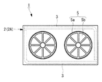
図1は本発明の実施形態に係る室外機の正面図であり、図2は図1のII矢視による平面図、図3は図1のIII−III線に沿う室外機の横断面図である。この室外機1は、例えばビル等の空調に用いられるマルチ空調システム、即ち1台の室外機に対して複数の図示しない室内機が接続される空調システムに用いられるものである。
Hereinafter, embodiments of the present invention will be described with reference to the drawings.
FIG. 1 is a front view of an outdoor unit according to an embodiment of the present invention, FIG. 2 is a plan view taken along arrow II in FIG. 1, and FIG. 3 is a cross-sectional view of the outdoor unit along line III-III in FIG. is there. The
室外機1の外殻をなす筐体2は、その上部を構成する熱交換器室2Aと、下部を構成する機械室2Bとを備えて構成されている。熱交換器室2Aは機械室2Bに対して分離可能であり、高さの異なるものに交換することもできる。熱交換器室2Aの内部には一対の熱交換器3が収容されている。これらの熱交換器3は平面視(図2参照)でL字形をしており、これら2つのL字形の熱交換器3が矩形をなすように組み合わされて熱交換器室2Aの4つの周面に沿っている。
A
また、筐体2(熱交換器室2A)の上面には、例えば2基の冷却ファン5が設置されている。これらの冷却ファン5は、筐体2の上面に形成されたベルマウス5aと、図示しないモーターに駆動されてベルマウス5aの内部で回転するファンブレード5bとを備えて構成されている。一方、機械室2Bの内部には、コントロールボックス7と、冷媒を圧縮する1基の圧縮機8と、図示しない四方弁、逆止弁、膨張弁、オイルセパレータ、レシーバ、気液分離器といった各種の空調装置構成機器類が収容されている。
For example, two cooling
機械室2Bは、その前面に開閉可能な点検蓋2L,2Rが設けられている。点検蓋2L,2Rは、図3に示すように手前側に開く両開き式、もしくはボルト等で締結される着脱式である。コントロールボックス7は、例えば向かって左側(右側でもよい)の点検蓋2Lの裏側となる機械室2Bの前面開口部に面して配置されている。
The
また、圧縮機8は、例えば向かって右側(左側でもよい)の点検蓋2Rの裏側となる機械室2Bの前面開口部に面して設置されており、コントロールボックス7に並ぶように配置されている。コントロールボックス7と圧縮機8の背面側には、それぞれオプション部品設置スペース10L,10Rが形成されている。これらのオプション部品設置スペース10L,10Rには、コントロールボックス7や圧縮機8よりもメンテナンス頻度の少ない部品群や、交換用部品(スペアパーツ)、工具類、検査器具類等が収容される。
The
以上のように構成された室外機1において、圧縮機8が作動して冷媒が圧縮されている時には、冷却ファン5が作動し、外気が熱交換器3を通過して熱交換器室2A内に吸い込まれ、冷却ファン5(ベルマウス5a)から外部に排出される。これにより熱交換器3が外気と熱交換され、熱交換器3の内部を流れる圧縮冷媒が凝縮または蒸発する。
In the
[第1実施形態]
図4は、本発明の第1実施形態を示すコントロールボックス7および電装部品冷却装置11Aの正面図であり、図5、図6、図7は、それぞれ正面図、側面図、後面図である。
[First Embodiment]
FIG. 4 is a front view of the
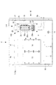
コントロールボックス7は、例えば板金材料や樹脂材料等によって形成されており、図3に示すように、機械室2Bの点検蓋2Lを開けた時に、手前側に向かって開口するボックス本体7Aと、このボックス本体7Aの開口部を閉塞する着脱可能なボックスリッド7Bとを備えている。ボックス本体7Aは図示しない固定構造によって機械室2Bの内部に固定されている。なお、図4にはボックスリッド7Bが取り外されたボックス本体7Aのみが示されている。
The
ボックス本体7Aの後面7aには、複数の基板13,14が設置されるとともに、複数の図示しない電気部品を固定するためのネジ穴15が穿設されている。なお、ボックス本体7Aの側面には、各基板13,14や各電気部品から延びる電線が束ねられた図示しないワイヤーハーネスを貫通させる防水グロメット17,18,19が嵌装されている。
A plurality of
そして、ボックス本体7Aの後面7aに電装部品冷却装置11Aが設けられている。この電装部品冷却装置11Aは、発熱性のあるパワートランジスタおよびダイオードモジュール等の電装部品21,22を冷媒の冷熱によって冷却するものであり、以下のように構成されている。
And the electrical
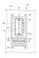
ボックス本体7Aの後面7aには、例えば縦に長い矩形の冷却用開口部24が穿設されている。この冷却用開口部24を後面7aの裏面側(外側)から塞ぐ形で、アルミニュームや銅等の良熱伝導材料から形成された、所定の厚みを有する板状のヒートシンク25が4本のビス26で固定されている。このヒートシンク25には、冷媒回路を構成する図示しない冷媒系統から延出させた冷媒配管28が貫通している。
On the
具体的には、冷媒配管28はヒートシンク25の下方から上方に貫通し、ヒートシンク25の上部でUターンして再びヒートシンク25を上方から下方に貫通している。これにより、冷媒配管28の内部を流れる冷媒の冷熱がヒートシンク25の表面に伝達され、ヒートシンク25の表面が冷却される。図6等に示すように、冷媒配管28はコントロールボックス7の外部に配置されている。
Specifically, the
図8に拡大して示すように、ヒートシンク25の正面、即ち、冷却用開口部24からコントロールボックス7(ボックス本体7A)の内部に露出する面に、例えば上下2箇所の電装部品固定部25a,25bが設けられている。これらの電装部品固定部25a,25bは、ヒートシンク25の正面に所定の間隔でビス孔(非図示)を穿設したものである。
As shown in FIG. 8 in an enlarged manner, on the front surface of the
発熱性のある電装部品21,22は、各電装部品固定部25a,25bにビス31,32で締結され、各電装部品21,22の底面がヒートシンク25に熱伝達可能に接触している。各電装部品21,22と各電装部品固定部25a,25bとの間に柔軟な熱伝達シートを介装したり、熱伝達剤を塗布する等してもよい。
The
ヒートシンク25の表面において、電装部品21,22が固定される電装部品固定部25a,25b以外の範囲を覆うように断熱部材35a〜35fが設けられている。この断熱部材35は、例えばシート状であり、所定の形状に切断されてヒートシンク25の表面に貼着されている。即ち、ヒートシンク25の正面に貼着される断熱部材35aと、後面に貼着される断熱部材35bと、両側面に貼着される断熱部材35c,35dと、上下面に貼着される断熱部材35e,35fとが設けられている。これらの断熱部材35a〜35fを分割せずに一体化して折り曲げたものとしてもよい。断熱部材35a〜35fの材質としては、発泡ポリエチレン、発泡クロロプレンゴム等を例示することができる。
On the surface of the
図8に示すように、断熱部材35aには、電装部品固定部25a,25bの面を露出させる矩形の開口部351,352が形成されている、この開口部351,352の内周輪郭形状は、電装部品21,22の外周輪郭形状に近い形状とされ、開口部351,352の内周縁部と電装部品21,22の外周輪郭との間でヒートシンク25の表面が極力露出しないようにされる。
As shown in FIG. 8,
また、このようなシート状の断熱部材35a〜35fを貼着する代わりに、図示しない塗料状の断熱部材をヒートシンク25の所定の範囲に塗布して硬化させるようにしてもよい。さらに、冷媒配管28の外周面にも、シート状、あるいは塗料状の断熱部材を設けてもよい。
Further, instead of sticking such sheet-like
以上のように構成された電装部品冷却装置11Aによれば、ヒートシンク25の内部を貫通する冷媒配管28を流れる冷媒の冷熱によってヒートシンク25の表面が冷却され、ヒートシンク25表面の電装部品固定部25a,25bに固定された発熱性のある電装部品21,22が冷却される。その際、ヒートシンク25の各面における電装部品固定部25a,25b以外の範囲に空気が触れることにより、空気中に含まれる水分が凝縮して結露水Wが発生する懸念がある。しかし、これらの範囲は断熱部材35a〜35fによって覆われているため、結露水Wが発生せず、結露水Wによって電装部品21,22に悪影響が及ぶことを防止できる。
According to the electric
また、ヒートシンク25の表面における電装部品固定部25a,25b以外の範囲に空気(コントロールボックス7内の雰囲気や外気)が触れても、この空気の温度(熱)が断熱部材35a〜35fに遮られてヒートシンク25および冷媒配管28には伝わらない。したがって、発熱性のある電装部品21,22のような冷却対象物以外の熱を冷媒が吸収してしまうことによる熱損失の増加、即ち、空調システムの効率低下を防止することができる。特に、機械室2Bの内部雰囲気は、圧縮機8等、他の装置や機器類が発する熱によって温度が高くなっているが、その熱がヒートシンク25を経て冷媒配管28に伝達されることを効果的に防止できる。
Further, even if air (atmosphere or outside air in the control box 7) touches a range other than the electrical
断熱部材35a〜35fをシート状に形成し、これをヒートシンク25の表面に貼着するようにしたことにより、ヒートシンク25の表面に断熱部材35a〜35fを容易に設置することができる。塗料状の断熱部材をヒートシンク25の表面に塗布して硬化させるようにした場合には、ヒートシンク25表面の隅々まで断熱部材を設置可能にし、結露水Wの発生をより効果的に抑制することができる。なお、シート状の断熱部材と塗料状の断熱部材とを併用してもよい。
Since the
[第2実施形態]
図9は、本発明の第2実施形態を示す電装部品冷却装置11Bの正面図である。この図9は、第1実施形態における図8に相当する図である。この電装部品冷却装置11Bは、ヒートシンク25の正面に断熱部材が貼着されておらず、その代わりに、ヒートシンク25正面の電装部品固定部25a,25bに固定された電装部品21,22の上方に堰状の結露水遮断部材41,42がそれぞれ設けられている。
[Second Embodiment]
FIG. 9 is a front view of an electrical
これらの結露水遮断部材41,42は、ヒートシンク25の正面に付着した結露水Wが流れ落ちた場合に、この結露水を電装部品21,22に対して遮断できる堰状に形成されている。即ち、各結露水遮断部材41,42は、下方に向かって開くチャンネル形状を有しており、各電装部品21,22の上部に位置する水平部41a,42aと、この水平部41a,42aの両端から下方に向かって垂下する一対の垂下部41b,42bとを備えている。
These condensed
水平部41a,42aは、その上辺が他端に向かって下方に傾斜している。本実施形態では、例えば上辺の、向かって左側の端部よりも右側の端部の方が低くなるように傾斜しており、右側の端部の角部が丸められている。また、垂下部41b,42bは、電装部品21,22の両側辺下端まで垂下し、その下端部が電装部品21,22の下縁よりも下方に位置している。
The upper sides of the
これらの結露水遮断部材41,42は、断熱材料により形成されていることが好ましい。例えば、第1実施形態で説明した断熱部材35a〜35fの材質である発泡ポリエチレン、発泡クロロプレンゴム等の材質である。
These condensed
以上のように構成された電装部品冷却装置11Bによれば、第1実施形態における電装部品冷却装置11Aと同様に、ヒートシンク25の内部を貫通する冷媒配管28を流れる冷媒の冷熱によってヒートシンク25の表面が冷却され、ヒートシンク25表面の電装部品固定部25a,25bに固定された発熱性のある電装部品21,22が冷却される。その際、ヒートシンク25の表面における電装部品固定部25a,25b以外の範囲に空気が触れることによって結露水Wが発生するが、この結露水Wが下方に流れ落ちても、堰状に形成された結露水遮断部材41,42に遮られて電装部品21,22には付着しない。このため、結露水Wによって電装部品21,22に悪影響が及ぶことを防止できる。
According to the electrical
結露水遮断部材41,42は、その水平部41a,42aの上辺が傾斜しているため、上方から流れて来る結露水Wは、結露水遮断部材41,42の上辺の傾斜に沿って流れ、結露水遮断部材41,42の端部から下方に流れ落ちる。このため、結露水Wが結露水遮断部材41,42を乗り越えて電装部品21,22に付着することを抑制し、電装部品21,22に悪影響が及ぶことを防止することができる。
The dew condensation
また、結露水遮断部材41,42の垂下部41b,42bが電装部品21,22の両側辺下端よりも下方まで延びているため、水平部41a,42aの上に流れ落ちた結露水Wが水平部41a,42aの端部から流下する際に垂下部41b,42bに遮られて電装部品21,22には付着しない。このため、結露水Wによって電装部品21,22に悪影響が及ぶことを防止できる。また、結露水遮断部材41,42を断熱材料で形成することにより、結露水遮断部材41,42自体の表面に結露水Wが生じることを防止することができる。
In addition, since the hanging
[第3実施形態]
図10は、本発明の第3実施形態を示す電装部品冷却装置11Cの正面図である。この電装部品冷却装置11Cにおいても、ヒートシンク25正面の電装部品固定部25a,25bに固定された電装部品21,22の上方に堰状の結露水遮断部材44,45がそれぞれ設けられている。これらの結露水遮断部材44,45は、第2実施形態における結露水遮断部材41,42(図9参照)と同様に、各電装部品21,22の上部に位置する水平部44a,45aと、この水平部44a,45aの両端から下方に向かって垂下する一対の垂下部44b,45bとを備えている。水平部44a,45aの上辺は第2実施形態と同様に傾斜している。
[Third Embodiment]
FIG. 10 is a front view of an electrical component cooling device 11C showing a third embodiment of the present invention. Also in this electrical component cooling device 11C, weir-shaped dew
垂下部44b,45bは、その長さが第2実施形態における結露水遮断部材41,42の垂下部41b,42bよりも短く、各電装部品21,22の両側辺下端よりも高い位置までの長さしかない。一方、垂下部44b,45bの幅は、第2実施形態における垂下部41b,42bよりも広くされ、垂下部44b,45bの下縁部は、内側(電装部品側)から外側に向かって下方に傾斜している。
The lengths of the hanging
以上のように構成された電装部品冷却装置11Cによれば、結露水遮断部材44,45の水平部44a,45a上に流れ落ちた結露水Wは、水平部44a,45aの端部から流下する際に垂下部44b,45bに遮られて電装部品21,22には付着しない。この垂下部44b,45bの長さは電装部品21,22の上下方向の長さよりも短いが、垂下部44b,45bの幅が広くされているため、垂下部44b,45bの外縁部を流れ落ちる結露水Wが電装部品21,22に付着しにくい。
また、垂下部44b,45bの下縁部が内側から外側に向かって下方に傾斜しているため、結露水Wの滴が垂下部44b,45bの下縁部を伝って電装部品21,22側に流れることはない。したがって、電装部品21,22を結露水Wから保護することができる。
According to the electrical component cooling device 11C configured as described above, the dew condensation water W that has flowed down on the
In addition, since the lower edge portions of the hanging
[第4実施形態]
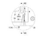
図11、図12、図13は、本発明の第4実施形態を示す電装部品冷却装置11Dの正面図である。この電装部品冷却装置11Dは、基本的に図9に示す第2実施形態の電装部品冷却装置11Bと同様な構成を備えているため、各部に同じ符号を付して説明を省略する。第2実施形態の電装部品冷却装置11Bとの相違点は、ヒートシンク25における電装部品固定部25a,25b側の面の下辺に、上方から下方に向かって幅および深さが拡大する錐状の切込部50が形成されている点である。この切込部50は角錐状でも円錐状でもよい。また、必ずしも上端が尖っていなくてもよく、例えば所定の幅を持ち、下方に向かって深くなるテーパー溝状等に形成してもよい。
[Fourth Embodiment]
11, FIG. 12, and FIG. 13 are front views of an electrical
図13に示すように、ヒートシンク25の下辺に形成された切込部50により、コントロールボックス7(後面7a)の内外が連通している。そして、図11,図12に示すように、結露水遮断部材41,42から流下する結露水Wが切込部50に流れるように、各結露水遮断部材41,42と切込部50との相対位置が設定されている。つまり、例えば下側の結露水遮断部材42における水平部42aの傾斜方向下り側に位置する垂下部42bの直下に切込部50が配置されている。
As shown in FIG. 13, the inside and outside of the control box 7 (
以上のように構成された電装部品冷却装置11Dによれば、結露水遮断部材41,42から流れ落ちる結露水Wが切込部50を経てヒートシンク25の裏面側に流れる。このため、結露水Wによって電装部品21,22に悪影響が及ぶことを防止できる。また、結露水Wがコントロールボックス7の底部に溜まることを防止することができる。
According to the electrical component cooling device 11 </ b> D configured as described above, the dew condensation water W flowing down from the dew condensation
[第5実施形態]
図14は、本発明の第5実施形態を示す電装部品冷却装置11Eの正面図である。この電装部品冷却装置11Eでは、ヒートシンク25の正面に複数の電装部品21,22が上下に、且つ水平方向にずれた位置に配置されたレイアウトとなっている。ここでは、上側の電装部品21に設けられた結露水遮断部材41から流下する結露水Wが、下側の電装部品22に設けられた前記結露水遮断部材42の水平部42aの上辺に垂れるように各結露水遮断部材41,42の相対位置が設定されている。具体的には、上側の結露水遮断部材41における水平部41aの傾斜方向下り側に位置する垂下部41bの直下に、下側の結露水遮断部材42における水平部42aの中間部が位置するように、両結露水遮断部材41,42の相対位置が設定されている。
[Fifth Embodiment]
FIG. 14 is a front view of an electrical
また、第4実施形態の電装部品冷却装置11Dと同様な切込部50がヒートシンク25の下辺に形成されている。この切込部50は、下側の結露水遮断部材42における水平部42aの傾斜方向下り側に位置する垂下部42bの直下に配置されている。
さらに、切込部50の両側には、結露水遮断部材41,42と同じく断熱材料により形成された楔形状の集水部材51,52が貼着されている。これらの集水部材51,52の上辺は、切込部50に向かって下がるように傾斜している。
Further, a
Further, wedge-shaped
以上のように構成された電装部品冷却装置11Bによれば、複数の結露水遮断部材41,42から流れ落ちる結露水Wを最終的に一箇所に集めることができるため、結露水Wの誘導処理が容易になる。また、この結露水Wは最終的に切込部50を経てヒートシンク25の裏面側に流れるため、結露水Wによって電装部品21,22に悪影響が及ぶことを防止することができる。
According to the electrical
以上説明したように、第1〜第5実施形態に係る電装部品冷却装置11A〜11E、およびこれを備えた空調システムの室外機1によれば、冷媒回路を流れる冷媒の冷熱により発熱性のある電装部品21,22を冷却するにあたり、結露水Wによって電装部品21,22に悪影響が及ぶことを防止することができる。また、冷却対象物以外の熱を冷媒が吸熱してしまうことを防止し、空調システムの効率が低下することを回避ができる。
As described above, according to the electrical
なお、本発明は上記実施形態の構成のみに限定されるものではなく、適宜変更や改良を加えることができ、このように変更や改良を加えた実施形態も本発明の権利範囲に含まれるものとする。 It should be noted that the present invention is not limited to the configuration of the above-described embodiment, and can be appropriately changed or improved. Embodiments with such changes and improvements are also included in the scope of the right of the present invention. And
例えば、上記各実施形態では、コントロールボックス7(ボックス本体7A)の後面7aに開設された冷却用開口部24に、コントロールボックス7の外部からヒートシンク25が固定され、このヒートシンク25のコントロールボックス7内部に露呈する表面に発熱性のある電装部品21,22が取り付けられた構成となっているが、必ずしもこの構成に限られることはない。
For example, in each of the above embodiments, the
また、第1実施形態の態様、即ちヒートシンク25の表面における電装部品固定部25a,25b以外の範囲を断熱部材35a〜35fの少なくとも1つを用いて覆う構成と、第2〜第5実施形態の少なくともいずれかの態様、即ちヒートシンクに固定された電装部品21,22の上方に堰状の結露水遮断部材41,42,44,45を設けたり、ヒートシンク25に切込部50および集水部材51,52を設けたりする構成とを組み合わせてもよい。
Moreover, the aspect of 1st Embodiment, ie, the structure which covers the ranges other than the electrical component fixing |
1 室外機
11A〜11E 電装部品冷却装置
21,22 電装部品
25 ヒートシンク
25a,25b 電装部品固定部
28 冷媒配管
35a〜35f 断熱部材
41,42,44,45 結露水遮断部材
41a,42a,44a,45a 水平部
41b,42b,44b,45b 垂下部
50 切込部
W 結露水
DESCRIPTION OF
Claims (11)
内部に前記冷媒配管が貫通し、該冷媒配管を流れる冷媒の冷熱が表面に伝達されるヒートシンクと、
前記ヒートシンクの表面に設けられた、発熱性のある電装部品を固定する電装部品固定部と、
前記ヒートシンクの表面における、前記電装部品固定部以外の範囲を覆うように設けられた断熱部材と、
を備えてなる電装部品冷却装置。 Refrigerant piping constituting the refrigerant system of the outdoor unit;
A heat sink through which the refrigerant pipe penetrates and the cold heat of the refrigerant flowing through the refrigerant pipe is transmitted to the surface;
An electrical component fixing part for fixing an exothermic electrical component provided on the surface of the heat sink;
A heat insulating member provided so as to cover a range other than the electric component fixing portion on the surface of the heat sink;
An electrical component cooling device comprising:
内部に前記冷媒配管が貫通し、該冷媒配管を流れる冷媒の冷熱が表面に伝達されるヒートシンクと、
前記ヒートシンクの表面に設けられた、発熱性のある電装部品を固定する電装部品固定部と、
前記ヒートシンクの表面における、前記電装部品固定部に固定された前記電装部品の上方に設けられた堰状の結露水遮断部材と、
を備え、
前記結露水遮断部材は、
前記電装部品の上部に位置する水平部と、
前記水平部の両端部から下方に向かって垂下する一対の垂下部と、を備えている電装部品冷却装置。 Refrigerant piping constituting the refrigerant circuit of the outdoor unit;
A heat sink through which the refrigerant pipe penetrates and the cold heat of the refrigerant flowing through the refrigerant pipe is transmitted to the surface;
An electrical component fixing part for fixing an exothermic electrical component provided on the surface of the heat sink;
A weir-shaped dew condensation water blocking member provided above the electric component fixed to the electric component fixing portion on the surface of the heat sink;
With
The condensed water blocking member is
A horizontal portion located at the top of the electrical component;
An electrical component cooling device comprising: a pair of hanging portions that hang downward from both ends of the horizontal portion.
内部に前記冷媒配管が貫通し、該冷媒配管を流れる冷媒の冷熱が表面に伝達されるヒートシンクと、
前記ヒートシンクの表面に設けられた、発熱性のある電装部品を固定する電装部品固定部と、
前記ヒートシンクの表面における、前記電装部品固定部以外の範囲を覆うように設けられた断熱部材と、
前記ヒートシンクの表面における、前記電装部品固定部に固定された前記電装部品の上方に設けられた堰状の結露水遮断部材と、
を備えてなり、
前記結露水遮断部材は、
前記電装部品の上部に位置する水平部と、
前記水平部の両端部から下方に向かって垂下する一対の垂下部と、を備えている電装部品冷却装置。 Refrigerant piping constituting the refrigerant system of the outdoor unit;
A heat sink through which the refrigerant pipe penetrates and the cold heat of the refrigerant flowing through the refrigerant pipe is transmitted to the surface;
An electrical component fixing part for fixing an exothermic electrical component provided on the surface of the heat sink;
A heat insulating member provided so as to cover a range other than the electric component fixing portion on the surface of the heat sink;
A weir-shaped dew condensation water blocking member provided above the electric component fixed to the electric component fixing portion on the surface of the heat sink;
With
The condensed water blocking member is
A horizontal portion located at the top of the electrical component;
An electrical component cooling device comprising: a pair of hanging portions that hang downward from both ends of the horizontal portion.
Priority Applications (4)
| Application Number | Priority Date | Filing Date | Title |
|---|---|---|---|
| JP2016094570A JP2017203575A (en) | 2016-05-10 | 2016-05-10 | Electrical component cooling device, outdoor unit of air conditioning system comprising the same |
| PCT/JP2017/017294 WO2017195712A1 (en) | 2016-05-10 | 2017-05-02 | Electrical component cooling device, and air conditioning system outdoor unit equipped with same |
| EP17796073.9A EP3401608A4 (en) | 2016-05-10 | 2017-05-02 | Electrical component cooling device, and air conditioning system outdoor unit equipped with same |
| CN201780009393.4A CN108603671A (en) | 2016-05-10 | 2017-05-02 | Electrical installation part cooling device and the outdoor unit for having its air-conditioning system |
Applications Claiming Priority (1)
| Application Number | Priority Date | Filing Date | Title |
|---|---|---|---|
| JP2016094570A JP2017203575A (en) | 2016-05-10 | 2016-05-10 | Electrical component cooling device, outdoor unit of air conditioning system comprising the same |
Publications (1)
| Publication Number | Publication Date |
|---|---|
| JP2017203575A true JP2017203575A (en) | 2017-11-16 |
Family
ID=60267248
Family Applications (1)
| Application Number | Title | Priority Date | Filing Date |
|---|---|---|---|
| JP2016094570A Pending JP2017203575A (en) | 2016-05-10 | 2016-05-10 | Electrical component cooling device, outdoor unit of air conditioning system comprising the same |
Country Status (4)
| Country | Link |
|---|---|
| EP (1) | EP3401608A4 (en) |
| JP (1) | JP2017203575A (en) |
| CN (1) | CN108603671A (en) |
| WO (1) | WO2017195712A1 (en) |
Cited By (5)
| Publication number | Priority date | Publication date | Assignee | Title |
|---|---|---|---|---|
| CN111442417A (en) * | 2020-04-09 | 2020-07-24 | 广东美的制冷设备有限公司 | Air conditioner, control method and control device thereof, and computer readable storage medium |
| JP2020148376A (en) * | 2019-03-13 | 2020-09-17 | 株式会社富士通ゼネラル | Outdoor unit |
| WO2021024410A1 (en) * | 2019-08-07 | 2021-02-11 | 三菱電機株式会社 | Chilling unit and air conditioner |
| JPWO2022038732A1 (en) * | 2020-08-20 | 2022-02-24 | ||
| CN114110913A (en) * | 2021-11-09 | 2022-03-01 | 珠海格力电器股份有限公司 | Air conditioning system, anti-condensation control method and device thereof, storage medium and processor |
Families Citing this family (1)
| Publication number | Priority date | Publication date | Assignee | Title |
|---|---|---|---|---|
| JP7313867B2 (en) * | 2019-04-02 | 2023-07-25 | 三菱重工サーマルシステムズ株式会社 | Cooling structure, electrical unit having the same, and outdoor unit |
Citations (9)
| Publication number | Priority date | Publication date | Assignee | Title |
|---|---|---|---|---|
| JPH05118672A (en) * | 1991-10-30 | 1993-05-14 | Mitsubishi Electric Corp | Electric component box of air conditioner |
| JP2001099448A (en) * | 1999-09-30 | 2001-04-13 | Toshiba Kyaria Kk | Outdoor unit of air conditioner |
| JP2008106948A (en) * | 2006-10-23 | 2008-05-08 | Daikin Ind Ltd | Drip-proof structure for terminal board of outdoor unit |
| JP2010114121A (en) * | 2008-11-04 | 2010-05-20 | Daikin Ind Ltd | Heat radiator of electrical component |
| WO2011083756A1 (en) * | 2010-01-05 | 2011-07-14 | ダイキン工業株式会社 | Refrigeration device |
| JP2011220654A (en) * | 2010-04-14 | 2011-11-04 | Daikin Industries Ltd | Refrigerating device |
| JP2013011392A (en) * | 2011-06-29 | 2013-01-17 | Panasonic Corp | Air conditioner |
| JP2015102295A (en) * | 2013-11-26 | 2015-06-04 | 三菱重工業株式会社 | Air conditioner |
| JP2015117924A (en) * | 2013-12-17 | 2015-06-25 | 株式会社ソキエ | Method of enhancing air-conditioning efficiency of air conditioner |
Family Cites Families (8)
| Publication number | Priority date | Publication date | Assignee | Title |
|---|---|---|---|---|
| JPS5126343B2 (en) | 1972-09-26 | 1976-08-05 | ||
| JPH0340007Y2 (en) * | 1986-02-28 | 1991-08-22 | ||
| JPH0350388U (en) * | 1989-09-22 | 1991-05-16 | ||
| CN2612912Y (en) * | 2003-05-07 | 2004-04-21 | 武汉凌云光电科技有限责任公司 | High power compact thermostatic device without liquid cooling |
| CN1696868A (en) * | 2005-04-25 | 2005-11-16 | 刘忠平 | Dustproof switching power supply for computer |
| WO2012081055A1 (en) * | 2010-12-16 | 2012-06-21 | パナソニック株式会社 | Cooling device and air conditioner provided therewith |
| WO2013001829A1 (en) * | 2011-06-29 | 2013-01-03 | パナソニック株式会社 | Cooling device and air conditioner with same |
| JP5941086B2 (en) * | 2014-03-25 | 2016-06-29 | ファナック株式会社 | Liquid-proof structure of electronic equipment |
-
2016
- 2016-05-10 JP JP2016094570A patent/JP2017203575A/en active Pending
-
2017
- 2017-05-02 CN CN201780009393.4A patent/CN108603671A/en active Pending
- 2017-05-02 EP EP17796073.9A patent/EP3401608A4/en not_active Withdrawn
- 2017-05-02 WO PCT/JP2017/017294 patent/WO2017195712A1/en active Application Filing
Patent Citations (9)
| Publication number | Priority date | Publication date | Assignee | Title |
|---|---|---|---|---|
| JPH05118672A (en) * | 1991-10-30 | 1993-05-14 | Mitsubishi Electric Corp | Electric component box of air conditioner |
| JP2001099448A (en) * | 1999-09-30 | 2001-04-13 | Toshiba Kyaria Kk | Outdoor unit of air conditioner |
| JP2008106948A (en) * | 2006-10-23 | 2008-05-08 | Daikin Ind Ltd | Drip-proof structure for terminal board of outdoor unit |
| JP2010114121A (en) * | 2008-11-04 | 2010-05-20 | Daikin Ind Ltd | Heat radiator of electrical component |
| WO2011083756A1 (en) * | 2010-01-05 | 2011-07-14 | ダイキン工業株式会社 | Refrigeration device |
| JP2011220654A (en) * | 2010-04-14 | 2011-11-04 | Daikin Industries Ltd | Refrigerating device |
| JP2013011392A (en) * | 2011-06-29 | 2013-01-17 | Panasonic Corp | Air conditioner |
| JP2015102295A (en) * | 2013-11-26 | 2015-06-04 | 三菱重工業株式会社 | Air conditioner |
| JP2015117924A (en) * | 2013-12-17 | 2015-06-25 | 株式会社ソキエ | Method of enhancing air-conditioning efficiency of air conditioner |
Cited By (9)
| Publication number | Priority date | Publication date | Assignee | Title |
|---|---|---|---|---|
| JP2020148376A (en) * | 2019-03-13 | 2020-09-17 | 株式会社富士通ゼネラル | Outdoor unit |
| WO2021024410A1 (en) * | 2019-08-07 | 2021-02-11 | 三菱電機株式会社 | Chilling unit and air conditioner |
| JPWO2021024410A1 (en) * | 2019-08-07 | 2021-12-23 | 三菱電機株式会社 | Chilling unit and air conditioner |
| CN111442417A (en) * | 2020-04-09 | 2020-07-24 | 广东美的制冷设备有限公司 | Air conditioner, control method and control device thereof, and computer readable storage medium |
| CN111442417B (en) * | 2020-04-09 | 2022-04-19 | 广东美的制冷设备有限公司 | Air conditioner, control method and control device thereof, and computer readable storage medium |
| JPWO2022038732A1 (en) * | 2020-08-20 | 2022-02-24 | ||
| JP7483012B2 (en) | 2020-08-20 | 2024-05-14 | 三菱電機株式会社 | Sheet member for refrigeration cycle device and method for manufacturing sheet member for refrigeration cycle device |
| CN114110913A (en) * | 2021-11-09 | 2022-03-01 | 珠海格力电器股份有限公司 | Air conditioning system, anti-condensation control method and device thereof, storage medium and processor |
| CN114110913B (en) * | 2021-11-09 | 2022-12-13 | 珠海格力电器股份有限公司 | Air conditioning system, anti-condensation control method and device thereof, storage medium and processor |
Also Published As
| Publication number | Publication date |
|---|---|
| CN108603671A (en) | 2018-09-28 |
| WO2017195712A1 (en) | 2017-11-16 |
| EP3401608A1 (en) | 2018-11-14 |
| EP3401608A4 (en) | 2019-03-06 |
Similar Documents
| Publication | Publication Date | Title |
|---|---|---|
| WO2017195712A1 (en) | Electrical component cooling device, and air conditioning system outdoor unit equipped with same | |
| EP2827691B1 (en) | Cabinet for power electronic apparatus | |
| EP2509304A1 (en) | Radiation unit of electronic device and electronic device using same | |
| EP1416230B1 (en) | Outdoor unit of air conditioner | |
| BR102013007321A2 (en) | heat exchanger for traction converters | |
| RU2362658C1 (en) | Welder inverter source | |
| JPWO2017022001A1 (en) | Air conditioner outdoor unit and air conditioner | |
| CN109915947B (en) | Air conditioner | |
| JPWO2019058472A1 (en) | Heat exchanger unit and air conditioner | |
| JP5811832B2 (en) | Air conditioner outdoor unit | |
| JP2015040673A (en) | Cooling structure of electrical component unit in outdoor unit of air conditioner | |
| JP5496697B2 (en) | Air conditioner outdoor unit | |
| JP6217969B2 (en) | Cooling structure in the machine room of an outdoor unit of an air conditioner | |
| KR100765197B1 (en) | Air conditioner | |
| US9877418B2 (en) | Motor drive device in which fan motor is exchangeable and control panel including same | |
| EP3327362B1 (en) | Outdoor unit of air conditioner | |
| JP5877359B2 (en) | Air conditioner outdoor unit | |
| JP6715858B2 (en) | Cooler that controls the temperature of the electronic enclosure | |
| JP2013015294A (en) | Cooling device and air conditioner with same | |
| US11118796B2 (en) | Outdoor unit for air conditioner | |
| JPH07277187A (en) | Control box for electric rolling stock | |
| JP6702346B2 (en) | Outdoor unit of refrigeration equipment | |
| JP3807353B2 (en) | Outdoor unit electrical unit and outdoor unit | |
| JP2014170765A (en) | Electronic device | |
| RU76271U1 (en) | WELDING INVERTER SOURCE |
Legal Events
| Date | Code | Title | Description |
|---|---|---|---|
| A711 | Notification of change in applicant |
Free format text: JAPANESE INTERMEDIATE CODE: A712 Effective date: 20170621 |
|
| A625 | Written request for application examination (by other person) |
Free format text: JAPANESE INTERMEDIATE CODE: A625 Effective date: 20190301 |
|
| A131 | Notification of reasons for refusal |
Free format text: JAPANESE INTERMEDIATE CODE: A131 Effective date: 20200303 |
|
| A02 | Decision of refusal |
Free format text: JAPANESE INTERMEDIATE CODE: A02 Effective date: 20200908 |