JP2017202147A - Heating cooker - Google Patents
Heating cooker Download PDFInfo
- Publication number
- JP2017202147A JP2017202147A JP2016096081A JP2016096081A JP2017202147A JP 2017202147 A JP2017202147 A JP 2017202147A JP 2016096081 A JP2016096081 A JP 2016096081A JP 2016096081 A JP2016096081 A JP 2016096081A JP 2017202147 A JP2017202147 A JP 2017202147A
- Authority
- JP
- Japan
- Prior art keywords
- lid
- reinforcing
- hinge
- hinge pin
- cooker
- Prior art date
- Legal status (The legal status is an assumption and is not a legal conclusion. Google has not performed a legal analysis and makes no representation as to the accuracy of the status listed.)
- Granted
Links
- 238000010438 heat treatment Methods 0.000 title claims abstract description 19
- 230000003014 reinforcing effect Effects 0.000 claims abstract description 162
- 239000002184 metal Substances 0.000 claims abstract description 40
- 229910052751 metal Inorganic materials 0.000 claims abstract description 40
- 238000010411 cooking Methods 0.000 claims description 17
- 229920003002 synthetic resin Polymers 0.000 claims description 13
- 239000000057 synthetic resin Substances 0.000 claims description 13
- 230000002787 reinforcement Effects 0.000 description 45
- 241000209094 Oryza Species 0.000 description 29
- 235000007164 Oryza sativa Nutrition 0.000 description 29
- 235000009566 rice Nutrition 0.000 description 29
- 210000000078 claw Anatomy 0.000 description 8
- 239000000463 material Substances 0.000 description 6
- 229920001971 elastomer Polymers 0.000 description 4
- 239000007788 liquid Substances 0.000 description 3
- 230000004048 modification Effects 0.000 description 3
- 238000012986 modification Methods 0.000 description 3
- 235000021329 brown rice Nutrition 0.000 description 2
- 238000005034 decoration Methods 0.000 description 2
- 239000000806 elastomer Substances 0.000 description 2
- 230000006698 induction Effects 0.000 description 2
- 230000001788 irregular Effects 0.000 description 2
- 150000002739 metals Chemical class 0.000 description 2
- 230000002093 peripheral effect Effects 0.000 description 2
- YCKRFDGAMUMZLT-UHFFFAOYSA-N Fluorine atom Chemical compound [F] YCKRFDGAMUMZLT-UHFFFAOYSA-N 0.000 description 1
- 235000010627 Phaseolus vulgaris Nutrition 0.000 description 1
- 244000046052 Phaseolus vulgaris Species 0.000 description 1
- 229920006311 Urethane elastomer Polymers 0.000 description 1
- 230000003796 beauty Effects 0.000 description 1
- 230000036760 body temperature Effects 0.000 description 1
- 238000009529 body temperature measurement Methods 0.000 description 1
- 235000008429 bread Nutrition 0.000 description 1
- 235000013339 cereals Nutrition 0.000 description 1
- 230000000295 complement effect Effects 0.000 description 1
- 235000021438 curry Nutrition 0.000 description 1
- 235000021186 dishes Nutrition 0.000 description 1
- 229910052731 fluorine Inorganic materials 0.000 description 1
- 239000011737 fluorine Substances 0.000 description 1
- 235000013305 food Nutrition 0.000 description 1
- 239000004615 ingredient Substances 0.000 description 1
- 238000003780 insertion Methods 0.000 description 1
- 230000037431 insertion Effects 0.000 description 1
- 238000009434 installation Methods 0.000 description 1
- 239000004973 liquid crystal related substance Substances 0.000 description 1
- 235000013372 meat Nutrition 0.000 description 1
- 239000007769 metal material Substances 0.000 description 1
- 229920000642 polymer Polymers 0.000 description 1
- 230000001105 regulatory effect Effects 0.000 description 1
- 229920002379 silicone rubber Polymers 0.000 description 1
- 239000004945 silicone rubber Substances 0.000 description 1
- 235000013547 stew Nutrition 0.000 description 1
- 235000013311 vegetables Nutrition 0.000 description 1
- 235000013618 yogurt Nutrition 0.000 description 1
Images


Landscapes
- Cookers (AREA)
Abstract
Description
この発明は、鍋内にセットされた調理物を加熱して調理する加熱調理器に関する。 The present invention relates to a cooking device that heats and cooks a food set in a pan.
例えば、特許文献1においては、鍋を収納する収納部が内側に設けられた調理器本体と、鍋の上面を覆う蓋体とを有する炊飯器が開示されている。蓋体は、調理器本体に対して開閉自在に構成されている。
For example, in
特許文献1の炊飯器では、蓋体を軸支するヒンジ部に設けられたヒンジバネによって、蓋体が開放方向に付勢されている。蓋体の開放動作を行うと、ヒンジバネの付勢力により、蓋体が開放方向に回動する。蓋体側の被回動係止部が調理器本体側の回動係止部に係止することにより、付勢された蓋体の回動が停止する。例えば、蓋体側の被回動係止部が蓋体の補強部材に設けられ、調理器本体側の回動係止部が調理器本体の肩部材に設けられ、蓋体側の被回動係止部が調理器本体側の回動係止部に係止される。
In the rice cooker of
蓋体の補強部材は、例えば、金属材料から構成されているため、強度的に特段の問題は無い。他方、調理器本体の肩部材は、複雑な形状に成型するために合成樹脂材から構成されているので、強度的に十分とは言えない。そこで、従来より、肩部材のストッパ部の肉厚の増加や、肩部材のストッパ部への補強リブの形成等の方策が講じられている。しかしながら、肩部材のストッパ部が合成樹脂材から構成されているため、その強度を向上させることに限界がある。そこで、開放方向に回動される蓋体を係止させる回動係止構造において、大幅な強度アップが望まれている。 Since the reinforcing member of the lid is made of, for example, a metal material, there is no particular problem in strength. On the other hand, the shoulder member of the cooker main body is made of a synthetic resin material to be molded into a complicated shape, so that it cannot be said that the strength is sufficient. Therefore, conventionally, measures such as increasing the thickness of the stopper portion of the shoulder member and forming reinforcing ribs on the stopper portion of the shoulder member have been taken. However, since the stopper portion of the shoulder member is made of a synthetic resin material, there is a limit to improving its strength. Therefore, a significant increase in strength is desired in the rotation locking structure that locks the lid that is rotated in the opening direction.
したがって、この発明の解決すべき技術的課題は、開放方向に回動された蓋体を調理器本体で係止させるのに十分な回動係止強度を有する加熱調理器を提供することである。 Therefore, the technical problem to be solved by the present invention is to provide a heating cooker having sufficient rotation locking strength to lock the lid rotated in the opening direction with the cooker body. .
上記技術的課題を解決するために、この発明によれば、以下の加熱調理器が提供される。 In order to solve the above technical problem, according to the present invention, the following cooking device is provided.
すなわち、この発明に係る加熱調理器は、
鍋を収容する調理器本体と、
ヒンジピンを中心にして前記調理器本体に回動可能に構成された蓋体と、
前記調理器本体の一部を構成する金属製の胴補強板とを備え、
前記胴補強板に配設されて前記ヒンジピンを軸支する金属製のヒンジ補強部には、回動係止部が形成されるとともに、前記蓋体の一部を構成する金属製の蓋補強板には、被回動係止部が形成され、
前記蓋体を開放方向に回動させたときに、前記被回動係止部が、前記回動係止部で係止されることを特徴とする。
That is, the cooking device according to the present invention is
A cooker body containing a pan,
A lid configured to be pivotable to the cooker body around a hinge pin;
A metal trunk reinforcing plate constituting a part of the cooker body,
The metal hinge reinforcing portion that is disposed on the trunk reinforcing plate and pivotally supports the hinge pin is formed with a rotation locking portion, and a metal lid reinforcing plate that constitutes a part of the lid body Is formed with a pivoted locking portion,
When the lid is rotated in the opening direction, the rotation locking portion is locked by the rotation locking portion.
この発明では、蓋体を開放方向に回動させたときに、金属製の蓋補強板に形成された被回動係止部が、金属製のヒンジ補強部に形成された回動係止部で係止されて、金属同士の回動係止構造になっているため、十分な回動係止強度を確保できる。したがって、加熱調理器は、開放方向に回動される蓋体を調理器本体で係止させるのに十分な回動係止強度を有する。 In this invention, when the lid body is rotated in the opening direction, the rotation locking portion formed on the metal lid reinforcing plate is the rotation locking portion formed on the metal hinge reinforcing portion. Since it has a metal-to-metal rotation locking structure, sufficient rotation locking strength can be ensured. Therefore, the heating cooker has sufficient rotation locking strength to lock the lid that is rotated in the opening direction with the cooker body.
前記回動係止部が、前記ヒンジ補強部において、前記ヒンジピンを軸支する軸受穴の上方に形成されていることが好ましい。このようにすれば、回動係止部と当接する蓋補強板の箇所と、回動軸であるヒンジピンとの距離を確保できるため、蓋体をスムーズに開けることができる。 It is preferable that the rotation locking portion is formed above a bearing hole that pivotally supports the hinge pin in the hinge reinforcing portion. In this way, the distance between the location of the lid reinforcing plate that contacts the rotation locking portion and the hinge pin that is the rotation axis can be ensured, so that the lid can be opened smoothly.
前記回動係止部と前記被回動係止部との間には、非金属製の係止受け部が配設されていることが好ましい。このようにすれば、金属製の被回動係止部が金属製の回動係止部にぶつかって金属同士の衝突音が発生するのを防止する。 It is preferable that a non-metallic engagement receiving portion is disposed between the rotation engagement portion and the rotation engagement portion. If it does in this way, it will prevent that the metal rotation latching | locking part collides with a metal rotation latching | locking part, and the collision sound of metals generate | occur | produces.
前記係止受け部が、合成樹脂製の肩部材のヒンジ接続部の上方に配設される合成樹脂製の肩カバーに形成されていることが好ましい。このようにすれば、肩カバーが肩部材のヒンジ接続部とは別部材になっているので、合成樹脂製の肩部材のヒンジ接続部において、強度低下を防止するとともに成型性を損なうことがない。 It is preferable that the latch receiving portion is formed on a synthetic resin shoulder cover disposed above the hinge connection portion of the synthetic resin shoulder member. In this way, since the shoulder cover is a separate member from the hinge connection portion of the shoulder member, the hinge connection portion of the shoulder member made of synthetic resin prevents a decrease in strength and does not impair the moldability. .
前記肩カバーが、前記鍋に向けて斜め下向きに傾斜した傾斜部を有することが好ましい。このようにすれば、蓋体を開放したときに蓋体の内面に付着していた液体が垂れてきても、鍋側に導いてヒンジ接続構造内に浸入するのを防止するとともに、ヒンジ接続構造を目隠しできる。 It is preferable that the shoulder cover has an inclined portion inclined obliquely downward toward the pan. In this way, even if the liquid adhering to the inner surface of the lid body drips when the lid body is opened, it is prevented from being introduced into the hinge connection structure by guiding it to the pan side, and the hinge connection structure Can be blindfolded.
この発明の加熱調理器では、蓋体を開放方向に回動させたときに、金属製の蓋補強板に形成された被回動係止部が、金属製のヒンジ補強部に形成された回動係止部で係止されて、金属同士の回動係止構造になっているため、十分な回動係止強度を確保できる。したがって、加熱調理器は、開放方向に回動される蓋体を調理器本体で係止させるのに十分な回動係止強度を有する。 In the heating cooker according to the present invention, when the lid is rotated in the opening direction, the rotation locking portion formed on the metal lid reinforcing plate is the rotation formed on the metal hinge reinforcing portion. Since it is locked by the dynamic locking portion and has a metal-to-metal rotation locking structure, sufficient rotation locking strength can be ensured. Therefore, the heating cooker has sufficient rotation locking strength to lock the lid that is rotated in the opening direction with the cooker body.
以下に、この発明の一実施形態に係る圧力式炊飯器1について、図1から図10を参照しながら説明する。
Below, the pressure
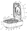
図1は、一実施形態に係る圧力式炊飯器(加熱調理器)1を示し、蓋体11の開放状態を示す斜視図である。図2は、蓋体11の閉鎖状態を示す斜視図である。
FIG. 1 is a perspective view showing a pressure rice cooker (heating cooker) 1 according to an embodiment and showing an open state of a
図1及び図2に示した圧力式炊飯器1は、例えば誘導加熱によって加熱される調理用の鍋3を着脱可能に収容する炊飯器本体(調理器本体)10と、該炊飯器本体10に対して回動可能に配設された蓋体11と、を備えている。
The pressure-
炊飯器本体10は、筒形状をなす胴体12と、該胴体12の下端開口を閉塞する底体22と、胴体12の上端開口を覆うように取り付ける肩部材32と、を有する外装体を備えている。肩部材32の上部は、装飾カバー34で部分的に覆われている。肩部材32の外周上部は、胴飾り体36で覆われている。肩部材32の下部には、鍋3の下部を加熱するヒータ(例えば、誘導加熱コイル)と、鍋3の温度を検知するための鍋温度センサとが配設されている。肩部材32の後方側には、蓋体11を回動可能に接続するためのヒンジ接続部21が設けられている。
The
肩部材32の前方側には、案内部46及び係合開口(被係合部)47を有する肩被係合部45が設けられている。案内部46は、ヒンジピン8のある後方側に斜め上向きに延びる傾斜面であり、ロック部材の一方を構成する係合爪部(係合部)23を係合開口47に案内する。ロック部材の他方を構成する係合開口47は、係合爪部23を受け入れる開口であり、係合爪部23と係合する。このように、係合開口47が炊飯器本体10に形成され、係合爪部23が蓋体11に形成されている。炊飯器本体10内には、制御基板(不図示)が配設されている。なお、胴体12の側面には、図示しないハンドルが取りつけられている。
A shoulder engaged
蓋体11は、ヒンジ接続部21のヒンジピン8を中心にして回動可能に取り付けられ、炊飯器本体10に対して閉じられたとき、炊飯器本体10の開口部を閉鎖する。蓋体11は、閉鎖状態で鍋3の側に位置する内側部材26と、内側部材26の上部外側を覆う外側部材25とを有する外装体を備える。内側部材26には、放熱板18と、蓋ヒータ(不図示)と、着脱可能に取り付けられる内蓋(不図示)とが配設されている。蓋体11が炊飯器本体10に対して閉じられたとき、蓋体11の内蓋が、鍋3の上端開口4を閉塞する。なお、内蓋が蓋体11に対して着脱可能である構成に限られず、内蓋が蓋体11に対して離脱不可である構成であってもよい。
The
蓋体11は、図2に示すように、外側部材25の後方側に排気通路の出口である蒸気排出口17を有する。蓋体11の内部には、鍋3内の温度を検知する蓋体温度センサ(不図示)が配設されている。さらに、上パネル14の前方側には、複数の入力スイッチを備える操作部19と、動作状況や操作状況を表示する液晶表示パネル等の表示部15とが配設されている。この制御基板に実装されたマイコン(制御部)によって、温度センサによる温度測定に基づいて、ヒータによる加熱(通電)が制御されている。また、操作部19や表示部15が、マイコンに接続されて、マイコンによってデータの入出力が制御されている。
As shown in FIG. 2, the
蓋体11の内側部材26は、炊飯器本体10の後方側に形成されたヒンジ接続部21に回動可能に装着されている。蓋体11は、ヒンジピン8に挿通されたヒンジバネ(不図示)によって開放方向に付勢されている。また、駆動ユニット7に組み込まれたダンパによって、蓋体11がゆっくりと開放されるように構成されている。閉鎖状態で内側部材26の鍋3への対向位置には放熱板18が配設される。そして、放熱板18の上側面には、鍋3内を加熱する蓋ヒータ(不図示)が配設されている。炊飯器本体10の後方側には、ヒンジピン8によって蓋体11を取り付けている部分を覆うヒンジカバー28が取り付けられている。
The
蓋体11の外側部材25の前方側には、蓋体11を開放するための開放操作部材16が配設されている。開放操作部材16は、その内面側に、係合開口47に対して係合ロック状態にある係合爪部23を解除方向に回動させるための押圧部を備える。開放操作部材16は、図示しないキックバネによって上向きに付勢されている。外側部材25の前方側には、蓋体11を自動的に閉鎖するためのスイッチとして働く閉鎖操作部材13が配設されている。炊飯器本体10の後方側であって、ヒンジ接続部21の下部には駆動ユニット7が設けられている。閉鎖操作部材13が押下されると、駆動ユニット7に内蔵された電動モータによって蓋体11が閉鎖方向に回動駆動され、蓋体11が自動的に閉鎖される。当該構成によれば、蓋体11の閉鎖動作を自動でスムーズに行うことができる。
An
次に、加熱調理時に発生する蒸気に起因した大きな力に抗するために、圧力式炊飯器1に配設された金属製の補強部について説明する。当該補強部は、調理器本体10の被係合部47側及びヒンジピン8側と、蓋体11とにそれぞれ配設されている。
Next, a description will be given of the metal reinforcing portion disposed in the
食材(例えば玄米)の入った鍋3内を閉塞状態で加熱すると、発生する蒸気で蓋体11を上方に押し上げる大きな力が作用する。この大きな力は、圧力式炊飯器1の被係合部47側では、係合爪部23と係合開口47とから構成されるロック部材によって支持されており、ロック部材に大きな力が作用する。大きな力は、炊飯器本体10及び蓋体11にも作用する。そのため、通常、合成樹脂材によって成型される炊飯器本体10及び蓋体11には、補強部材として働く金属製の蓋補強板40及び胴補強板50が配設されている。この発明の圧力式炊飯器1では、補強部として、新規の補強部材と、従来から使用されている補強部材を補強するための補強要素が配設されている。
When the inside of the
まず、図3を参照しながら、蓋体11に配設された補強部を説明する。
First, the reinforcement part arrange | positioned at the
蓋体11を補強するための補強部材は、従来から使用されている。この実施形態に係る蓋補強板40は、蓋体11の一部を構成して、図3に示すように、板状の蓋補強本体41を有し、該蓋補強本体41は、左右一対の側方補強部41aと、左右一対の側方補強部41aに連結される前方補強部41c及び後方補強部41dとを有する。左右一対の側方補強部41aと前方補強部41c及び後方補強部41dとで囲まれた空間には、蓋体11に必要な構成要素、例えば調圧装置、駆動機構及び蒸気ユニット等が配置される。
A reinforcing member for reinforcing the
左右一対の側方補強部41aは、係合部23側からヒンジピン8側に前後方向に延びているが、ヒンジピン8側の後側部41jの外面が係合部23側の前側部41hの外面よりも外方に位置し、ヒンジピン8側の後側部41jの内面が係合部23側の前側部41hの内面よりも外方に位置した異形形状をしている。すなわち、左右一対の側方補強部41aにおいて、係合部23側が内側寄りであり、ヒンジピン8側が外側寄りであり、両者をつなぐ中間部が幅広に構成された異形形状をしている。従来の側方補強部が、前後方向に直線状に延びているのに対して、この実施形態での側方補強部41aは、前後方向に異形に延びている。そして、左右一対の側方補強部41aと平面視で相似形状をしている金属製の左右一対の側方補強体42が、左右一対の側方補強部41aの上に装着されている。左右一対の側方補強体42においても、ヒンジピン8側の後側部42jの外面が係合部23側の前側部42hの外面よりも外方に位置し、ヒンジピン8側の後側部42jの内面が係合部23側の前側部42hの内面よりも外方に位置している。左右一対の側方補強部41aと側方補強体42とは、ネジ止めで一体化されている。
The pair of left and right
当該構成によれば、左右一対の側方補強部41a及び側方補強体42のヒンジピン8側の後側部41j,42j同士の間隔が拡大するので、蓋体11を自動で閉じるための駆動ユニット7を設置するための設置スペースを大きく確保できる。また、左右一対の側方補強部41a及び側方補強体42の係合部23側の前側部41h,42h同士の間隔が狭いので、被係合部47の周りの強度低下を抑制できる。
According to the said structure, since the space | interval of the
左右一対の側方補強部41a及び側方補強体42において、前側部41h,42hと後側部41j,42jとの間に位置する中間部41i,42iが、前側部41h,42h及び後側部41j,42jよりも幅広に構成されている。当該構成によれば、左右一対の側方補強部41aにおいて、変形しやすい中間部41i,42iを補強できる。したがって、金属製の左右一対の側方補強部41a及び側方補強体42は、蓋補強板40を補強するための補強要素として働く。
In the pair of left and right
図3に示すように、蓋補強本体41は、大きな開口を有する。蓋補強本体41の大きな開口には、蒸気排出口17に連通する蒸気ユニット27や、内側部材26の内面(上面)から上方に突出するボス等が配設される。大きな開口により、蒸気ユニット27等の設置の自由度が大きくなる。しかしながら、蓋補強本体41の大きな開口は、強度的に不利な方向に作用する。係合部23側からヒンジピン8側への前後方向は、左右一対の側方補強部41a及び側方補強体42で補強されているが、板状の前方補強部41c及び後方補強部41dでは強度的に不十分である。そのため、左右一対の側方補強部41a及び側方補強体42と直交する直交方向(左右方向)が補強される。
As shown in FIG. 3, the
前方補強部41cには、左右一対の側方補強部41aと直交する直交方向に直線状に延びる金属製の補強ピンが配設される。後方補強部41dの側では、左右一対の側方補強部41aと直交する非直線状の金属製の補強バーが、蓋補強板40上に配設されている。非直線状の補強バーは、立体的形状をした蒸気ユニット27との干渉を避けるように、クランク形状をしている。クランク形状をした補強バーの脚部は、蓋補強板40のバー取付部49にネジで固定される。上記の補強ピン及び補強バーによって、蓋補強板40において、左右一対の側方補強部41a及び側方補強体42の直交方向が補強される。したがって、金属製の補強ピン及び補強バーは、蓋補強板40を補強するための補強要素として働く。
The front reinforcing
また、左右一対の側方補強部41aのヒンジピン8側の端部には、ヒンジ受け部43がそれぞれ形成され、各ヒンジ受け部43には、蓋側係合穴44が形成されている。各蓋側係合穴44には、ヒンジピン8の左右の蓋側軸部8b(図9及び10に図示)がそれぞれ嵌挿される。左右一対の側方補強部41aのヒンジピン8側の後側部41jの内面には、被回動係止部48がそれぞれ形成されている。被回動係止部48のそれぞれは、左右一対の側方補強部41aと直交する直交方向(左右方向)に板状に延びている。各被回動係止部48は、金属製の蓋補強板40に形成された被回動係止部として働く。各被回動係止部48は、蓋体11を回動させて開放状態にしたとき、後述するヒンジ補強体70の回動係止部74に係止されて、蓋体11の回動が規制される。
In addition, a
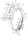
つぎに、図4から図6を参照しながら、炊飯器本体10に配設された補強部を説明する。
Below, the reinforcement part arrange | positioned at the rice cooker
図3に示す合成樹脂製の肩部材32の下部には、図4に示す金属製の胴補強板50が配設されている。肩部材32は、図3に示すように、板状で略リング形状をした肩本体と、肩本体の前方部に形成された覆い部と、肩本体の後方部に形成されたヒンジ接続部21とを有する。胴補強板50は、調理器本体10の一部を構成して炊飯器本体10を補強する補強部材として働き、図5に示すように、板状で略リング形状をした胴補強本体51と、胴補強本体51の左右の側端から下方に延びる左右の側部52とを有する。胴補強板50は、胴補強本体51の前端から上方に延びる前取付部53と、胴補強本体51の後端から上方に延びる後取付部56とを有する。前取付部53及び後取付部56は、ネジ穴を有する。前取付部53には、複数の前被係止孔54が形成されている。
A metal
胴補強板50の前方すなわち図3の係合開口47側には、胴補強板50とは別体である金属製のフック受け補強体60が配設されている。フック受け補強体60は、クランク形状に折曲されて、上板部61と脚部62と左右の下板部63と前当接部64とを有する。脚部62及び前当接部64は、それぞれ、前方に突出した前係止突起65を複数個有する。各前係止突起65が、前取付部53での対応する前被係止孔(前被係止部)54に挿入されることで、フック受け補強体60が胴補強板50の前取付部53に安定的に係止される。また、フック受け補強体60の左右の下板部63と上板部61が、それぞれ、胴補強本体51の前方部に対してネジで固定される。また、フック受け補強体60の前当接部64が、胴補強板50の前取付部53に対してネジで固定される。したがって、フック受け補強体60が、胴補強板50に容易に且つ確実に固定される。
A metal
加熱調理時に発生する蒸気で蓋体11の係合開口47側を上方に押し上げる大きな力が働いたとき、前被係止孔54への前係止突起65の係止によって、当該大きな力に抗することができる。ネジによる固定構造に加えて、前被係止孔54への前係止突起65の係止構造により、胴補強板50へのフック受け補強体60の取付が、補強されている。
When a large force that pushes the
肩部材32と一体化されたフック受け補強体60は、係合開口47の一部分を構成しており、係合ロック状態ではフック受け補強体60の上板部61が蓋体11の係合爪部23と係合する。係合開口47すなわち肩部材32の被係合部47側が、フック受け補強体60によって補強されている。したがって、フック受け補強体60は、調理器本体10の係合開口47側を補強するための補強部材として働く。また、フック受け補強体60の前被係止孔54は、フック受け補強体60を補強するための補強要素として働く。
The
上述したように、フック受け補強体60の上板部61が、胴補強本体51の前方部に対してネジで固定されるが、上板部61が下板部63よりも上方に位置するため、上板部61と胴補強本体51の前方部とを接続するための長尺の接続ネジが使用される。当該接続ネジは、側面視で視認される可能性があり、係合開口47周りの美感を損なう。また、胴補強本体51の前方部には、ネジ止め用の貫通穴が形成されており、当該貫通穴を通じて液体が調理器本体10の内部に浸入する可能性がある。そこで、係合開口47には、接続ネジを隠す目隠し部が設けられている。目隠し部は、接続ネジを挿通するための挿通穴を有する隆起段部であり、肩部材32の一部として構成されている。なお、目隠し部は、肩部材32とは別体の部材として構成することもできる。
As described above, the
また、肩部材32への胴補強板50及びフック受け補強体60の組み立ては、胴補強板50を肩部材32の肩本体に装着し、フック受け補強体60を肩部材32の覆い部に差し込み、フック受け補強体60を胴補強板50に係止し且つネジ固定することで、行われる。
Further, the
胴補強板50の後方すなわちヒンジピン8側には、胴補強板50とは別体である金属製のヒンジ補強体(ヒンジ補強部)70が配設されている。ヒンジ補強体70は、調理器本体10のヒンジピン8側を補強するための補強部材として働く。ヒンジ補強体70は、図5に示すように、クランク形状に折曲されて、本体部71と左右の軸支部72と左右の取付部75とを有する。本体部71は、平面視、U字形状をしている。本体部71と後取付部56とで囲まれたスペースには、駆動ユニット7が収納される。本体部71の両側には、左右方向に延びる板状の取付部75がそれぞれ形成されている。各取付部75の外側には、前後方向及び上下方向に延びる板状の軸支部72がそれぞれ形成されている。
A metal hinge reinforcement body (hinge reinforcement portion) 70, which is a separate body from the
左右の取付部75には、それぞれ、ネジ止め用の貫通穴が複数個形成されている。左右の取付部75は、胴補強板50の後取付部56に当接した状態でネジ止めされる。左右の取付部75の下端部には、前方に突出した後係止突起76がそれぞれ形成されている。左右の取付部75を後取付部56にネジ止めしたときに、各後係止突起76が胴補強本体51の後方部の下面51a(図6に図示)と係止するように構成されている。当該構成によれば、後係止突起76の上面及び下面51aという面同士が当接して確実に係止することができ、胴補強板50における後被係止部の加工が不要になりコストダウンを図ることができる。
A plurality of through holes for screwing are formed in the left and
加熱調理時に発生する蒸気で蓋体11のヒンジピン8側を上方に押し上げる大きな力が働いたとき、胴補強本体51の下面51aへの後係止突起76の係止によって、当該大きな力に抗することができる。胴補強本体51の後方部の下面51aは、後被係止部として働く。ネジによる固定構造に加えて、胴補強本体51の下面51aへの後係止突起76の係止構造により、胴補強板50へのヒンジ補強体70の取付が、補強されている。したがって、肩部材32のヒンジピン8側が、ヒンジ補強体70によって補強されているので、ヒンジ補強体70の後係止突起76は、調理器本体10のヒンジピン8側を補強するための補強要素として働く。
When a large force that pushes the
図8を参照しながら、ヒンジピン8周りの回動係止構造を説明する。図8は、ヒンジピン8周りの回動係止構造を後方から見た斜視図である。
The rotation locking structure around the
左右の軸支部72の上部には、回動係止部74がそれぞれ形成されている。左右の軸支部72は、軸受穴73をそれぞれ有し、各軸受穴73の上方には、回動係止部74がそれぞれ形成されている。各軸受穴73は、ヒンジピン8の本体側軸部8cを回動可能に軸支する。当該構成によれば、回動係止部74と当接する蓋補強板40の箇所(すなわち被回動係止部48)と、回動軸であるヒンジピン8との距離を確保できるため、蓋体11をスムーズに開けることができる。
On the upper portions of the left and right
ヒンジ補強体70の回動係止部74は、蓋体11を回動させて開放状態にしたとき、蓋補強板40の被回動係止部48を係止して、蓋体11の回動を約90度に規制する。このように、各回動係止部74は、金属製の胴補強板50に取り付けられるとともにヒンジピン8を軸支する金属製のヒンジ補強体70に形成されたストッパ部として働く。
The
肩部材32のヒンジ接続部21の上方には、合成樹脂製の肩カバー29が配設されて、肩カバー29がヒンジ接続部21にネジ止めされている。肩カバー29が、傾斜部29aと左右の係止受け部29bとを有する。傾斜部29aは、肩カバー29の中央部に形成されて、鍋3に向けて斜め下向きに傾斜している。肩カバー29の傾斜部29aによって、蓋体11を開放したときに蓋体11の内面に付着していた液体が垂れてきても、鍋3側に導いてヒンジ接続構造内に浸入するのを防止するとともに、ヒンジ接続構造を目隠しできる。
A synthetic
左右の係止受け部29bは、肩カバー29の左右の端部に形成されて、上方に延びている。左右の係止受け部29bを肩部材32のヒンジ接続部21とは別部材の肩カバー29に形成することにより、合成樹脂製の肩部材32のヒンジ接続部21において、強度低下を防止するとともに成型性を損なうことがない。
The left and right
左右の係止受け部29bの前部には、蓋補強板40の被回動係止部48を係止するための係止面が形成されている。左右の係止受け部29bの後部には、ヒンジ補強体70の回動係止部74を装着するための凹部が形成されている。回動係止部74が、合成樹脂製の肩カバー29の係止受け部29bの凹部に装着されている。すなわち、金属製の回動係止部74の前面には、合成樹脂製の(非金属製の)係止受け部29bが配設されている。当該構成によれば、金属製の被回動係止部48が金属製の回動係止部74にぶつかって金属同士の衝突音が発生するのを防止する。したがって、蓋補強板40の被回動係止部48は、肩カバー29の係止受け部29bを介してヒンジ補強体70の回動係止部74に係止されて、蓋体11の回動が約90度に規制される。
A locking surface for locking the pivoted locking
図8に示すように、破線で示されたヒンジピン8がヒンジブッシュ9に挿通されている。ヒンジブッシュ9の外側には、図示しないヒンジバネが装着されて、ヒンジバネによって蓋体11が開放方向に付勢されている。
As shown in FIG. 8, the
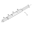
ヒンジピン8は、上述した左右一対の側方補強部41a及び側方補強体42と直交する直交方向(左右方向)に延びている。ヒンジピン8は、端部側から中央側に向けて、例えば、図9に示すように、軸本体8aと蓋側軸部8bと本体側軸部8cと駆動軸部8dとを有する。蓋側軸部8bは、断面視で非円形のトラック形状をしており、蓋補強板40に形成された相補的形状の蓋側係合穴44に係合する。本体側軸部8cは、断面視で円形形状をしており、ヒンジ補強体70に形成された円形形状の軸受穴73で軸支される。駆動軸部8dは、断面視で非円形のトラック形状をしており、駆動ユニット7内に構成された駆動出力部(不図示)に係合する。
The
蓋側軸部8b及び駆動軸部8dにおいて、トラック形状というのは、蓋側軸部8b及び駆動軸部8dが、側面視で左右の円筒状部分と上下の平面状部分とから構成されていることを指している。図9に示したヒンジピン8では、蓋側軸部8b及び駆動軸部8dの各平面状部分が、平行に延在している。
In the lid-
駆動ユニット7の電動モータからの力は、駆動出力部及び駆動軸部8dを介して、軸受穴73で軸支されたヒンジピン8に伝達される。ヒンジピン8に伝達された力は、蓋側軸部8b及び蓋側係合穴44を介して、蓋体11の蓋補強板40に伝達される。蓋体11の蓋補強板40に伝達された力によって、蓋体11が閉鎖方向に回動されて、蓋体11が閉鎖される。このように、ヒンジピン8の非円形部は、ヒンジピン8に働く力を受け入れる入力部又はヒンジピン8から外部に力を出力する出力部として使用される。
The force from the electric motor of the drive unit 7 is transmitted to the
図10は、ヒンジピン8の変形例を示す。図10のヒンジピン8は、図9に示したヒンジピン8と同様に、左右一対の側方補強部41a及び側方補強体42と直交する直交方向(左右方向)に延びて、端部側から中央側に向けて、軸本体8aと蓋側軸部8bと本体側軸部8cと駆動軸部8dとを有する。蓋側軸部8bは、断面視で非円形のトラック形状をしており、蓋補強板40に形成された円形形状の蓋側係合穴44に係合する。本体側軸部8cは、断面視で円形形状をしており、ヒンジ補強体70に形成された円形形状の軸受穴73で軸支される。駆動軸部8dは、断面視で非円形のトラック形状をしており、駆動ユニット7内に構成された駆動出力部(不図示)に係合する。図10に示したヒンジピン8では、蓋側軸部8b及び駆動軸部8dの各平面状部分が、互いに直交するように延在している。
FIG. 10 shows a modification of the
以上のように、圧力式炊飯器1では、蓋体11を開放方向に回動させたときに、金属製の蓋補強板40に形成された被回動係止部48が、金属製のヒンジ補強体70に形成された回動係止部74で係止されて、金属同士の回動係止構造になっているため、十分な回動係止強度を確保できる。したがって、加熱調理器1は、開放方向に回動される蓋体11を調理器本体10で係止させるのに十分な回動係止強度を有する。
As described above, in the
なお、この発明の理解を容易にするために、具体的な構成や数字を用いて説明したが、この発明は、上述した各実施形態の具体的な構成や数字に限定されるものではなく、特許請求の範囲に記載した内容を逸脱しない範囲で考えられる各種の変形例を含むことができる。 In order to facilitate understanding of the present invention, the description has been made using specific configurations and numbers, but the present invention is not limited to the specific configurations and numbers of the above-described embodiments, Various modifications that can be considered without departing from the scope of the claims can be included.
上記実施形態では、ヒンジ補強部70が、胴補強板50とは別体の金属製ヒンジ補強体70として構成されている。ヒンジ補強部70は、例えば、胴補強板50の胴補強本体51又は後取付部56の一部分が後方に延在して所定のヒンジ補強形状を形作ることによって、金属製の胴補強板50と一体的に形成された構成とすることもできる。
In the above-described embodiment, the
係止受け部29bは、肩カバー29を肩部材32と一体化して、一体化された肩部材32のヒンジ接続部21の上部の左右に形成される構成であってもよい。係止受け部29bは、エラストマーのような弾性体からなるキャップ状の別部材として、ヒンジ補強体70の回動係止部74又は蓋補強板40の被回動係止部48に装着して、回動係止部74と被回動係止部48との間に配設される構成とすることもできる。
The
ヒンジピン8に形成される非円形部は、対応する係合穴等と係合して力を伝達する形状であればよく、断面視で、キー溝が形成された円形形状や、正六角形状や楕円形状や正多角形状等の様々な形状とすることができる。そして、対応する係合穴等は、ヒンジピン8に形成される非円形部と相補的な形状をしている。
The non-circular portion formed on the
駆動ユニット7を蓋体11の側に配設することができる。また、ヒンジピン8が、端部側から中央側に向けて、軸本体8aと本体側軸部8cと蓋側軸部8bと駆動軸部8dとを有して、本体側軸部8c及び駆動軸部8dが、断面視で非円形部から構成され、蓋側軸部8bが、断面視で円形部から構成されてもよい。
The drive unit 7 can be disposed on the
調理器本体10の上端外周部と蓋体11の下端外周部との間の間隙には、例えば、シリコーン系ゴムやフッ素系ゴムやウレタン系ゴム等のゴム材料やエラストマー材料等の高分子弾性体から構成される可撓性のある間隙緩衝体が配設される態様であってもよい。間隙緩衝体が柔軟に且つ弾性的に折れ曲がるため、調理器本体10及び蓋体11に対する手指の意図しない干渉を防止できる。また、間隙緩衝体は着脱可能な態様や取り外し不可の固定式とする態様であってもよい。この発明は、電動モータによって蓋体11が自動的に閉鎖されるものや、蓋体11が手動で閉鎖されるものに適用することができる。
In the gap between the upper end outer peripheral portion of the
この発明は、加熱調理器として火の通りにくい玄米等を炊飯する圧力式炊飯器1を例に挙げて説明したが、他の高圧下での加熱調理(例えば、すね肉やスペアリブ、カレーやシチューなどの煮込み料理、煮豆、穀物類や根菜類の調理)を行う圧力式加熱調理器にも適用可能である。また、この発明は、お米を炊飯する圧力式又は非圧力式の炊飯器や、他の調理物(例えば、ケーキ生地、パン、ヨーグルト、蒸し物)を加熱して調理する加熱調理器にも適用可能である。
The present invention has been described by taking as an example the pressure-
1 圧力式炊飯器(加熱調理器)
3 鍋
4 上端開口
7 駆動ユニット
8 ヒンジピン
8a 軸本体
8b 蓋側軸部
8c 本体側軸部
8d 駆動軸部
9 ヒンジブッシュ
10 炊飯器本体(調理器本体)
11 蓋体
12 胴体
13 閉鎖操作部材
14 上パネル
15 表示部
16 開放操作部材
17 蒸気排出口
18 放熱板
19 操作部
21 ヒンジ接続部
22 底体
23 係合爪部(係合部)
25 外側部材
26 内側部材
28 ヒンジカバー
29 肩カバー
29a 傾斜部
29b 係止受け部
32 肩部材
34 装飾カバー
36 胴飾り体
40 蓋補強板
41 蓋補強本体
41a 側方補強部
41c 前方補強部
41d 後方補強部
41h 前側部
41i 中間部
41j 後側部
42 側方補強体
42h 前側部
42i 中間部
42j 後側部
43 ヒンジ受け部
44 蓋側係合穴
45 肩被係合部
46 案内部
47 係合開口(被係合部)
48 被回動係止部
49 バー取付部
50 胴補強板
51 胴補強本体
51a 下面(後被係止部)
52 側部
53 前取付部
54 前被係止孔(前被係止部)
56 後取付部
60 フック受け補強体
61 上板部
62 脚部
63 下板部
64 前当接部
65 前係止突起
70 ヒンジ補強体(ヒンジ補強部)
71 本体部
72 軸支部
73 軸受穴
74 回動係止部
75 取付部
76 後係止突起
1 Pressure rice cooker (heating cooker)
3 Pan 4 Upper end opening 7
DESCRIPTION OF
25
48 Rotating locking
52
56
71
Claims (5)
ヒンジピンを中心にして前記調理器本体に回動可能に構成された蓋体と、
前記調理器本体の一部を構成する金属製の胴補強板とを備え、
前記胴補強板に配設されて前記ヒンジピンを軸支する金属製のヒンジ補強部には、回動係止部が形成されるとともに、前記蓋体の一部を構成する金属製の蓋補強板には、被回動係止部が形成され、
前記蓋体を開放方向に回動させたときに、前記被回動係止部が、前記回動係止部で係止される、加熱調理器。 A cooker body containing a pan,
A lid configured to be pivotable to the cooker body around a hinge pin;
A metal trunk reinforcing plate constituting a part of the cooker body,
The metal hinge reinforcing portion that is disposed on the trunk reinforcing plate and pivotally supports the hinge pin is formed with a rotation locking portion, and a metal lid reinforcing plate that constitutes a part of the lid body Is formed with a pivoted locking portion,
A heating cooker in which the rotation locking portion is locked by the rotation locking portion when the lid is rotated in the opening direction.
Priority Applications (1)
| Application Number | Priority Date | Filing Date | Title |
|---|---|---|---|
| JP2016096081A JP6683537B2 (en) | 2016-05-12 | 2016-05-12 | Heating cooker |
Applications Claiming Priority (1)
| Application Number | Priority Date | Filing Date | Title |
|---|---|---|---|
| JP2016096081A JP6683537B2 (en) | 2016-05-12 | 2016-05-12 | Heating cooker |
Publications (2)
| Publication Number | Publication Date |
|---|---|
| JP2017202147A true JP2017202147A (en) | 2017-11-16 |
| JP6683537B2 JP6683537B2 (en) | 2020-04-22 |
Family
ID=60323047
Family Applications (1)
| Application Number | Title | Priority Date | Filing Date |
|---|---|---|---|
| JP2016096081A Active JP6683537B2 (en) | 2016-05-12 | 2016-05-12 | Heating cooker |
Country Status (1)
| Country | Link |
|---|---|
| JP (1) | JP6683537B2 (en) |
Cited By (2)
| Publication number | Priority date | Publication date | Assignee | Title |
|---|---|---|---|---|
| CN108814276A (en) * | 2018-08-09 | 2018-11-16 | 珠海格力电器股份有限公司 | Connection structure and cooking appliance |
| JP2020062241A (en) * | 2018-10-18 | 2020-04-23 | 株式会社パロマ | rice cooker |
Citations (3)
| Publication number | Priority date | Publication date | Assignee | Title |
|---|---|---|---|---|
| JPH04135222U (en) * | 1991-06-11 | 1992-12-16 | 象印マホービン株式会社 | Braking device for opening/closing lid |
| JP2002000445A (en) * | 2000-06-20 | 2002-01-08 | Zojirushi Corp | Lid of rice cooker |
| JP2007236508A (en) * | 2006-03-07 | 2007-09-20 | Zojirushi Corp | Pressure type rice cooker |
-
2016
- 2016-05-12 JP JP2016096081A patent/JP6683537B2/en active Active
Patent Citations (3)
| Publication number | Priority date | Publication date | Assignee | Title |
|---|---|---|---|---|
| JPH04135222U (en) * | 1991-06-11 | 1992-12-16 | 象印マホービン株式会社 | Braking device for opening/closing lid |
| JP2002000445A (en) * | 2000-06-20 | 2002-01-08 | Zojirushi Corp | Lid of rice cooker |
| JP2007236508A (en) * | 2006-03-07 | 2007-09-20 | Zojirushi Corp | Pressure type rice cooker |
Cited By (3)
| Publication number | Priority date | Publication date | Assignee | Title |
|---|---|---|---|---|
| CN108814276A (en) * | 2018-08-09 | 2018-11-16 | 珠海格力电器股份有限公司 | Connection structure and cooking appliance |
| JP2020062241A (en) * | 2018-10-18 | 2020-04-23 | 株式会社パロマ | rice cooker |
| JP7217502B2 (en) | 2018-10-18 | 2023-02-03 | 株式会社パロマ | rice cooker |
Also Published As
| Publication number | Publication date |
|---|---|
| JP6683537B2 (en) | 2020-04-22 |
Similar Documents
| Publication | Publication Date | Title |
|---|---|---|
| KR100878255B1 (en) | Electric pressure cooker capable of separating lid of inner pot having safety device | |
| KR20090098213A (en) | Washing machine | |
| EP3091153B1 (en) | Locking device for a door of a domestic appliance | |
| JP2017202147A (en) | Heating cooker | |
| EP0371611B1 (en) | Cabinet for cooking appliances | |
| JP6111826B2 (en) | rice cooker | |
| KR20080109427A (en) | Electric pressure cooker capable of separating lid of inner pot having safety device | |
| JP2017202124A (en) | Heating cooker | |
| JP4762931B2 (en) | rice cooker | |
| JP5426478B2 (en) | Handle mounting structure | |
| JP6538603B2 (en) | Cooker | |
| KR102132485B1 (en) | Cooking appliance | |
| JP4823792B2 (en) | Household appliances | |
| JP5201006B2 (en) | Cooker | |
| KR102065079B1 (en) | Safety device for oven locking in multi-cooker | |
| CN209846856U (en) | Cooking utensil | |
| CN210018921U (en) | Cooking appliance and cooking appliance cover | |
| JP2015213692A (en) | Heating apparatus | |
| CN217001319U (en) | Lock structure and cooking utensil | |
| CN220522281U (en) | Cooking utensil | |
| CN211722824U (en) | Lid subassembly and cooking utensil | |
| CN211324426U (en) | Cooking utensil | |
| CN116624029A (en) | Door assembly of cooking utensil and cooking utensil | |
| CN116446729A (en) | Door assembly of cooking utensil and cooking utensil | |
| JP4285436B2 (en) | Electric cooker |
Legal Events
| Date | Code | Title | Description |
|---|---|---|---|
| A621 | Written request for application examination |
Free format text: JAPANESE INTERMEDIATE CODE: A621 Effective date: 20181024 |
|
| A131 | Notification of reasons for refusal |
Free format text: JAPANESE INTERMEDIATE CODE: A131 Effective date: 20191001 |
|
| A977 | Report on retrieval |
Free format text: JAPANESE INTERMEDIATE CODE: A971007 Effective date: 20190927 |
|
| A521 | Request for written amendment filed |
Free format text: JAPANESE INTERMEDIATE CODE: A523 Effective date: 20191127 |
|
| TRDD | Decision of grant or rejection written | ||
| A01 | Written decision to grant a patent or to grant a registration (utility model) |
Free format text: JAPANESE INTERMEDIATE CODE: A01 Effective date: 20200324 |
|
| A61 | First payment of annual fees (during grant procedure) |
Free format text: JAPANESE INTERMEDIATE CODE: A61 Effective date: 20200326 |
|
| R150 | Certificate of patent or registration of utility model |
Ref document number: 6683537 Country of ref document: JP Free format text: JAPANESE INTERMEDIATE CODE: R150 |
|
| R250 | Receipt of annual fees |
Free format text: JAPANESE INTERMEDIATE CODE: R250 |