JP2017201316A - Multi-mode detection - Google Patents
Multi-mode detection Download PDFInfo
- Publication number
- JP2017201316A JP2017201316A JP2017119399A JP2017119399A JP2017201316A JP 2017201316 A JP2017201316 A JP 2017201316A JP 2017119399 A JP2017119399 A JP 2017119399A JP 2017119399 A JP2017119399 A JP 2017119399A JP 2017201316 A JP2017201316 A JP 2017201316A
- Authority
- JP
- Japan
- Prior art keywords
- detection
- particle
- particles
- smoke
- air volume
- Prior art date
- Legal status (The legal status is an assumption and is not a legal conclusion. Google has not performed a legal analysis and makes no representation as to the accuracy of the status listed.)
- Pending
Links
- 238000001514 detection method Methods 0.000 title claims abstract description 465
- 239000002245 particle Substances 0.000 claims abstract description 471
- 239000000779 smoke Substances 0.000 claims abstract description 153
- 238000000034 method Methods 0.000 claims abstract description 95
- 230000005855 radiation Effects 0.000 claims description 215
- 238000004458 analytical method Methods 0.000 claims description 53
- 238000012795 verification Methods 0.000 claims description 34
- 230000000007 visual effect Effects 0.000 claims description 26
- 238000012360 testing method Methods 0.000 claims description 22
- 230000008569 process Effects 0.000 claims description 15
- 230000003213 activating effect Effects 0.000 claims description 14
- 239000000126 substance Substances 0.000 claims description 12
- 230000004913 activation Effects 0.000 claims description 7
- 230000008859 change Effects 0.000 claims description 6
- 238000005259 measurement Methods 0.000 claims description 3
- 238000009434 installation Methods 0.000 claims description 2
- 230000003993 interaction Effects 0.000 claims description 2
- 230000002123 temporal effect Effects 0.000 claims description 2
- 238000012546 transfer Methods 0.000 claims description 2
- 238000011179 visual inspection Methods 0.000 claims description 2
- 230000002829 reductive effect Effects 0.000 abstract description 3
- 238000000354 decomposition reaction Methods 0.000 abstract 1
- 238000005070 sampling Methods 0.000 description 26
- 238000012544 monitoring process Methods 0.000 description 22
- 230000007246 mechanism Effects 0.000 description 17
- 230000001960 triggered effect Effects 0.000 description 16
- 230000000875 corresponding effect Effects 0.000 description 14
- 238000004891 communication Methods 0.000 description 13
- 230000003287 optical effect Effects 0.000 description 10
- 230000004044 response Effects 0.000 description 10
- 230000003434 inspiratory effect Effects 0.000 description 7
- 230000035945 sensitivity Effects 0.000 description 6
- 230000009471 action Effects 0.000 description 5
- 238000001994 activation Methods 0.000 description 5
- 238000010586 diagram Methods 0.000 description 5
- 238000012549 training Methods 0.000 description 5
- 230000006870 function Effects 0.000 description 4
- 230000008901 benefit Effects 0.000 description 3
- 238000003384 imaging method Methods 0.000 description 3
- 238000007689 inspection Methods 0.000 description 3
- 238000011835 investigation Methods 0.000 description 3
- 230000000670 limiting effect Effects 0.000 description 3
- 239000004509 smoke generator Substances 0.000 description 3
- 238000012790 confirmation Methods 0.000 description 2
- 230000002596 correlated effect Effects 0.000 description 2
- 238000005516 engineering process Methods 0.000 description 2
- 230000001360 synchronised effect Effects 0.000 description 2
- 238000004879 turbidimetry Methods 0.000 description 2
- 238000004378 air conditioning Methods 0.000 description 1
- 230000033228 biological regulation Effects 0.000 description 1
- 230000008878 coupling Effects 0.000 description 1
- 238000010168 coupling process Methods 0.000 description 1
- 238000005859 coupling reaction Methods 0.000 description 1
- 230000003247 decreasing effect Effects 0.000 description 1
- 238000009792 diffusion process Methods 0.000 description 1
- 230000005670 electromagnetic radiation Effects 0.000 description 1
- 230000002349 favourable effect Effects 0.000 description 1
- 238000010191 image analysis Methods 0.000 description 1
- 238000002347 injection Methods 0.000 description 1
- 239000007924 injection Substances 0.000 description 1
- 230000010354 integration Effects 0.000 description 1
- 230000002452 interceptive effect Effects 0.000 description 1
- 230000004807 localization Effects 0.000 description 1
- 230000007257 malfunction Effects 0.000 description 1
- 239000011164 primary particle Substances 0.000 description 1
- 238000012545 processing Methods 0.000 description 1
- 238000011895 specific detection Methods 0.000 description 1
- 238000001228 spectrum Methods 0.000 description 1
- 230000003068 static effect Effects 0.000 description 1
- 230000000153 supplemental effect Effects 0.000 description 1
- 230000001629 suppression Effects 0.000 description 1
- 238000010998 test method Methods 0.000 description 1
- 238000005979 thermal decomposition reaction Methods 0.000 description 1
- 238000011144 upstream manufacturing Methods 0.000 description 1
- 238000001429 visible spectrum Methods 0.000 description 1
Images


Classifications
-
- G—PHYSICS
- G08—SIGNALLING
- G08B—SIGNALLING OR CALLING SYSTEMS; ORDER TELEGRAPHS; ALARM SYSTEMS
- G08B17/00—Fire alarms; Alarms responsive to explosion
- G08B17/10—Actuation by presence of smoke or gases, e.g. automatic alarm devices for analysing flowing fluid materials by the use of optical means
-
- G—PHYSICS
- G06—COMPUTING; CALCULATING OR COUNTING
- G06T—IMAGE DATA PROCESSING OR GENERATION, IN GENERAL
- G06T7/00—Image analysis
- G06T7/40—Analysis of texture
-
- G—PHYSICS
- G08—SIGNALLING
- G08B—SIGNALLING OR CALLING SYSTEMS; ORDER TELEGRAPHS; ALARM SYSTEMS
- G08B17/00—Fire alarms; Alarms responsive to explosion
- G08B17/12—Actuation by presence of radiation or particles, e.g. of infrared radiation or of ions
- G08B17/125—Actuation by presence of radiation or particles, e.g. of infrared radiation or of ions by using a video camera to detect fire or smoke
-
- G—PHYSICS
- G08—SIGNALLING
- G08B—SIGNALLING OR CALLING SYSTEMS; ORDER TELEGRAPHS; ALARM SYSTEMS
- G08B29/00—Checking or monitoring of signalling or alarm systems; Prevention or correction of operating errors, e.g. preventing unauthorised operation
- G08B29/18—Prevention or correction of operating errors
- G08B29/183—Single detectors using dual technologies
-
- G—PHYSICS
- G06—COMPUTING; CALCULATING OR COUNTING
- G06T—IMAGE DATA PROCESSING OR GENERATION, IN GENERAL
- G06T2207/00—Indexing scheme for image analysis or image enhancement
- G06T2207/10—Image acquisition modality
- G06T2207/10016—Video; Image sequence
-
- G—PHYSICS
- G06—COMPUTING; CALCULATING OR COUNTING
- G06T—IMAGE DATA PROCESSING OR GENERATION, IN GENERAL
- G06T2207/00—Indexing scheme for image analysis or image enhancement
- G06T2207/30—Subject of image; Context of image processing
- G06T2207/30232—Surveillance
-
- G—PHYSICS
- G08—SIGNALLING
- G08B—SIGNALLING OR CALLING SYSTEMS; ORDER TELEGRAPHS; ALARM SYSTEMS
- G08B17/00—Fire alarms; Alarms responsive to explosion
- G08B17/10—Actuation by presence of smoke or gases, e.g. automatic alarm devices for analysing flowing fluid materials by the use of optical means
- G08B17/11—Actuation by presence of smoke or gases, e.g. automatic alarm devices for analysing flowing fluid materials by the use of optical means using an ionisation chamber for detecting smoke or gas
- G08B17/113—Constructional details
Abstract
Description
本発明は、空気容量中の粒子の存在を検出する粒子検出器に関し、より詳細には、マルチ検出モードを使用して、粒子の存在を検出する検出システムに関する。好ましくは、検出される粒子は、実際の火、ぼや、又は煙等の熱分解を示す粒子である。 The present invention relates to a particle detector that detects the presence of particles in an air volume, and more particularly to a detection system that detects the presence of particles using a multi-detection mode. Preferably, the particles to be detected are particles that exhibit thermal decomposition such as actual fire, haze, or smoke.
煙及び火検出システムは、多くの家庭、ビジネス、インフラ設備、及び機関において生命及び資産の保護を保証する根本要素である。 Smoke and fire detection systems are a fundamental element that ensures the protection of life and assets in many homes, businesses, infrastructure facilities, and institutions.
そのようなシステムは、検出器が、監視中のロケーションでの空気容量(空気空間)中の粒子の存在を検出することができるロケーション(位置)に、検出器を配置する。 Such a system places the detector at a location where the detector can detect the presence of particles in the air volume (air space) at the location being monitored.
イオン化チャンバ内の粒子の存在を検出するイオン化検出器、比濁計を含む光学煙検出器、及び空気サンプルを通る光ビームを用いて遮蔽度を測定することにより、解析チャンバ内の空気サンプル中の粒子の存在を検出する遮蔽度モニタを含め、様々な異なるタイプの粒子検出器を使用して、監視中の容量から引き込まれた空気サンプル内の煙を検出することができる。 An ionization detector that detects the presence of particles in the ionization chamber, an optical smoke detector that includes a nephelometer, and a light beam that passes through the air sample to measure the degree of shielding in the air sample in the analysis chamber. A variety of different types of particle detectors can be used, including occlusion monitors that detect the presence of particles, to detect smoke in an air sample drawn from the volume being monitored.
監視中のエリアから引き込まれる空気サンプルに対して動作するこれらのタイプの検出器に加えて、最近では、煙又は火に関して監視されている領域における空気容量で直接、オープンエリア粒子検出を実行することが試みられている。例えば、ビデオ煙検出は、ビデオ解析技法を使用して、煙又は火が、カメラによって撮像中のシーンに存在するか否かを判断する。ビーム検出器も知られている。このタイプの検出器は基本的に、チャンバなしで動作するが、その代わりに光ビームを、監視中の空気容量を横切って放射して、容量中の煙を直接識別する遮蔽度検出器である。 In addition to these types of detectors operating on air samples drawn from the monitored area, recently performing open area particle detection directly at the air volume in the area being monitored for smoke or fire Has been tried. For example, video smoke detection uses video analysis techniques to determine whether smoke or fire is present in the scene being imaged by the camera. Beam detectors are also known. This type of detector basically operates without a chamber, but instead is a shielding detector that directly emits a light beam across the air volume being monitored to directly identify the smoke in the volume. .
Xtralis Pty Ltd社は、比濁計と同様に動作するが、粒子検出チャンバ内の空気サンプルに対して動作する代わりに、放射線ビームを監視中の容量に伝達させ、容量の一連のビデオ画像においてビームからの散乱光を検出することを含む能動的なビデオ煙検出を含む更なる技法も開発した。Xtralis Pty Ltd社は、複数の波長の放射線及びビデオ画像捕捉を使用して、放射線ビームを遮蔽する粒子を検出する強化型ビーム検出器技法も開発した。煙粒子の検出は、ビームのビデオ画像を使用して、複数の波長での遮蔽度の比較を実行することを含む。 Xtralis Pty Ltd operates in the same way as a nephelometer, but instead of operating on an air sample in the particle detection chamber, it transmits the radiation beam to the volume being monitored and the beam in a series of video images of the volume. Additional techniques have also been developed that include active video smoke detection including detecting scattered light from. Xtralis Pty Ltd also developed an enhanced beam detector technique that uses multiple wavelengths of radiation and video image capture to detect particles that block the radiation beam. Smoke particle detection involves performing a shielding comparison at multiple wavelengths using a video image of the beam.
これらの全ての異なる技術及び技法にも拘わらず、粒子、特に煙を検出しようとする場合になお利益の相反がある。例えば、一方では、予防措置を可能にするために、又は少なくとも火が制御不可能になる前に行動をとろうとするために、早期に粒子を検出することが望ましい。これを行うためには、高感度機器が望ましい。他方、過度に感度の高い機器は、頻繁な誤検出に繋がるおそれがあり、誤検出は気を散らし、対処にコストがかかる。さらに、煙検出システムを使用して、火の厳密なロケーションを特定することが望ましい。これは、ポイント(又はスポット)検出器を使用して達成することが難しいことがあり、その理由は、監視中のエリアに多数のポイント(又はスポット)検出器を配置する必要があり、それが非現実的に高価であるためである。ビデオ煙検出システムはこれらの欠点のうちの幾つかを克服するが、煙の検出において信頼性がより低く、監視されている容量内の干渉物体に起因する誤検出をより発生させやすい。 Despite all these different technologies and techniques, there are still conflicts of interest when trying to detect particles, especially smoke. For example, on the one hand, it is desirable to detect particles early in order to allow precautionary measures or at least to take action before the fire becomes uncontrollable. In order to do this, a sensitive device is desirable. On the other hand, devices with excessively high sensitivity may lead to frequent false detections, which are distracting and costly to deal with. In addition, it is desirable to use a smoke detection system to identify the exact location of the fire. This can be difficult to achieve using point (or spot) detectors because it is necessary to place a large number of point (or spot) detectors in the area being monitored, This is because it is unrealistically expensive. Video smoke detection systems overcome some of these drawbacks, but are less reliable in detecting smoke and are more prone to false detection due to interfering objects in the volume being monitored.
粒子検出器の故障又は誤作動の結果は深刻であるため、これらのシステムは通常、使用に関する厳密な基準及び規制によっても影響される。これは、煙及び火の監視に関して敷地所有者が利用できる選択肢が通常、これらの法的に要求される基準を満たすシステムに制限されることを意味する。 Because the consequences of particle detector failures or malfunctions are severe, these systems are usually also affected by strict standards and regulations for use. This means that the options available to site owners for smoke and fire monitoring are usually limited to systems that meet these legally required standards.
したがって、煙及び他の粒子を検出するより柔軟なシステムが必要とされるとともに、エンドユーザにとってより好ましい方法で、上述したトレードオフのうちの幾つかに対処することも必要とされる。 Therefore, there is a need for a more flexible system for detecting smoke and other particles, as well as addressing some of the trade-offs described above in a manner that is more favorable to the end user.
本明細書におけるいかなる従来技術への参照も、この従来技術が、濠国又は任意の他の法域において共通一般知識の一部をなすこと、又はこの従来技術が、当業者によって関連するものとして確認され、理解され、見なされることが妥当に予期可能であることの承認又はいずれの形態での示唆ではなく、そのように解釈されるべきではない。 Reference to any prior art in this specification confirms that this prior art forms part of common general knowledge in Korea or any other jurisdiction, or that this prior art is relevant by those skilled in the art. It should not be construed as an admission or in any way suggesting that it is reasonably foreseeable, understood and considered.
本発明の第1の態様では、空気容量中の粒子を検出する粒子検出装置が提供され、この装置は、空気容量を表す空気サンプルの中の粒子の存在を検出する内部検出器と、空気容量の少なくとも一部を通して放射線ビームを投射して、容量中の粒子と相互作用し、それにより、空気容量中の粒子の存在の検出を可能にする少なくとも1つの放射線エミッタとを含む。好ましくは、粒子は煙粒子である。 In a first aspect of the invention, a particle detection device is provided for detecting particles in an air volume, the device comprising an internal detector for detecting the presence of particles in an air sample representative of the air volume, and an air volume. Including at least one radiation emitter that projects a radiation beam through at least a portion thereof to interact with particles in the volume, thereby allowing detection of the presence of particles in the air volume. Preferably the particles are smoke particles.
好ましくは、粒子検出装置は、放射線ビームの少なくとも一部からの放射線を検知するように位置決めされる少なくとも1つのセンサを含む。より好ましくは、センサは、放射線ビームの少なくとも一部の画像を捕捉するように位置決めされるカメラである。 Preferably, the particle detection device includes at least one sensor positioned to detect radiation from at least a portion of the radiation beam. More preferably, the sensor is a camera that is positioned to capture an image of at least a portion of the radiation beam.
本発明の第2の態様では、空気容量中の粒子を検出する粒子検出装置が提供され、この装置は、空気容量を表す空気サンプルの中の粒子の存在を検出する内部検出器と、空気容量を通る放射線ビームの少なくとも一部から情報を取得し、取得された相互作用を解析して、空気容量中の粒子の存在を示すように位置決めされる少なくとも1つのセンサとを含む。好ましくは、センサは、放射線ビームの少なくとも一部の画像を捕捉するように位置決めされるカメラである。 In a second aspect of the invention, a particle detection device is provided for detecting particles in an air volume, the device comprising an internal detector for detecting the presence of particles in an air sample representative of the air volume, and an air volume. And at least one sensor positioned to indicate the presence of particles in the air volume by acquiring information from at least a portion of the radiation beam passing through and analyzing the acquired interaction. Preferably, the sensor is a camera positioned to capture an image of at least a portion of the radiation beam.
本発明の第3の態様では、空気容量中の粒子を検出する粒子検出装置が提供され、この装置は、空気容量を表す空気サンプルの中の粒子の存在を検出する内部検出器と、空気容量の一連の画像を捕捉し、空気容量中の粒子の検出を可能にするように構成される少なくとも1つのカメラとを含む。好ましくは、この装置は、一連の画像を解析して、空気容量中の粒子の存在を検出するプロセッサシステムを含む。一形態では、プロセッサは、ビデオ解析技法を適用して、噴煙及び/又は炎のうちの一方又は両方が、一連の画像内に存在することを検出することができる。代替又は追加として、プロセッサは、一連の画像において、容量中に放射される放射線の存在を検出し、それにより、放射された放射線と相互作用する粒子を検出することができる。 In a third aspect of the invention, a particle detection device is provided for detecting particles in an air volume, the device comprising an internal detector for detecting the presence of particles in an air sample representative of the air volume, and an air volume. And at least one camera configured to allow detection of particles in the air volume. Preferably, the apparatus includes a processor system that analyzes a series of images to detect the presence of particles in the air volume. In one form, the processor can apply video analysis techniques to detect that one or both of the plumes and / or flames are present in the series of images. Alternatively or additionally, the processor can detect the presence of radiation emitted in the volume in a series of images, thereby detecting particles that interact with the emitted radiation.
上述した各粒子検出装置は、マルチモード粒子検出システムの構成要素として使用し得る。さらに、粒子検出への、上述したマルチモード粒子検出装置の使用が提供される。 Each of the particle detection devices described above can be used as a component of a multi-mode particle detection system. Further provided is the use of the multi-mode particle detector described above for particle detection.
本発明の第4の態様では、空気容量中の粒子を検出するマルチモード粒子検出システムが提供され、このシステムは、少なくとも1つの粒子検出装置を含み、少なくとも1つの粒子検出装置は、空気容量を表す空気サンプルの中の粒子の存在を検出する内部検出器と、空気容量の少なくとも一部を通る放射線ビームを投射する少なくとも1つの放射線エミッタとを含み、システムは、放射線ビームの少なくとも一部から情報を取得するように位置決めされる少なくとも1つのセンサと、放射線ビームの少なくとも一部からの情報を解析して、空気容量中の粒子を検出する解析手段とを更に含む。一実施形態では、少なくとも1つのセンサは、粒子検出装置の構成要素として統合し得、又は代替的には、少なくとも1つのセンサは、粒子検出装置とは別個であり得る。 In a fourth aspect of the invention, a multi-mode particle detection system for detecting particles in an air volume is provided, the system including at least one particle detection device, the at least one particle detection device having an air volume. An internal detector for detecting the presence of particles in the representing air sample and at least one radiation emitter for projecting a radiation beam through at least a portion of the air volume, wherein the system receives information from at least a portion of the radiation beam. And at least one sensor positioned to obtain the signal and analysis means for analyzing information from at least a portion of the radiation beam to detect particles in the air volume. In one embodiment, the at least one sensor may be integrated as a component of the particle detection device, or alternatively, the at least one sensor may be separate from the particle detection device.
本発明の第5の態様では、空気容量中の粒子を検出するマルチモード粒子検出システムが提供され、システムは、少なくとも1つの粒子検出装置を含み、少なくとも1つの粒子検出装置は、空気容量を表す空気サンプルの中の粒子の存在を検出する内部検出器と、放射線ビームの少なくとも一部から情報を取得するように位置決めされる少なくとも1つのセンサとを含み、システムは、空気容量の少なくとも一部を通る放射線ビームを投射する少なくとも1つの放射線エミッタと、放射線ビームの少なくとも一部からの情報を解析して、空気容量中の粒子を検出する解析手段とを更に含む。 In a fifth aspect of the invention, a multi-mode particle detection system for detecting particles in an air volume is provided, the system including at least one particle detection device, the at least one particle detection device representing an air volume. An internal detector for detecting the presence of particles in the air sample and at least one sensor positioned to obtain information from at least a portion of the radiation beam, the system comprising at least a portion of the air volume It further includes at least one radiation emitter for projecting a radiation beam therethrough, and analysis means for analyzing information from at least a portion of the radiation beam to detect particles in the air volume.
本発明の第6の態様では、空気容量中の粒子を検出するマルチモード粒子検出システムが提供され、このシステムは、空気容量中の粒子の存在を検出する内部検出器を有する粒子検出装置を含む、内部検出モードを定義する装置と、外部検出モードを定義する装置とを含み、外部検出モードを定義する装置は、空気容量の少なくとも一部を通る放射線ビームを投射する少なくとも1つの放射線エミッタと、放射線ビームの少なくとも一部から情報を取得するように位置決めされる少なくとも1つのセンサと、放射線ビームの少なくとも一部からの情報を解析して、空気容量中の粒子を検出する解析手段とを含み、内部検出モードの粒子検出装置及び外部検出モードの少なくとも1つの放射線エミッタ又は少なくとも1つのセンサのうちの両方又は一方は、一体装置を形成する。 In a sixth aspect of the invention, a multi-mode particle detection system for detecting particles in an air volume is provided, the system including a particle detection device having an internal detector that detects the presence of particles in the air volume. An apparatus for defining an internal detection mode and an apparatus for defining an external detection mode, the apparatus for defining an external detection mode comprising: at least one radiation emitter that projects a radiation beam through at least a portion of the air volume; At least one sensor positioned to obtain information from at least a portion of the radiation beam; and analyzing means for analyzing information from at least the portion of the radiation beam to detect particles in the air volume; Both the particle detection device in internal detection mode and at least one radiation emitter or at least one sensor in external detection mode Is one form an integral unit.
本発明の一実施形態では、上述した任意のシステムは、システムの構成要素として、放射線ビームを反射するか、又はリダイレクトする反射器を更に含み得る。 In one embodiment of the present invention, any of the systems described above may further include a reflector that reflects or redirects the radiation beam as a component of the system.
好ましくは、少なくとも1つの粒子検出装置及び反射器は別個の装置であるが、反射器は、粒子検出装置に統合し得る。 Preferably, the at least one particle detector and the reflector are separate devices, but the reflector can be integrated into the particle detector.
好ましくは、少なくとも1つのセンサは、放射線ビームの少なくとも一部の画像を捕捉するように位置決めされるカメラである。 Preferably, the at least one sensor is a camera that is positioned to capture an image of at least a portion of the radiation beam.
好ましくは、カメラは、粒子検出装置とは別個の装置であるが、カメラは粒子検出装置に統合し得る。 Preferably, the camera is a separate device from the particle detection device, but the camera can be integrated into the particle detection device.
好ましくは、解析手段は、画像で捕捉される散乱放射線を使用して、粒子が空気容量中に存在するか否かを判断する。この散乱放射線は、前方散乱放射線又は後方散乱放射線の何れかであり得る。本発明の別の態様では、上述したマルチモード粒子検出システムの設置が提供される。 Preferably, the analysis means uses scattered radiation captured in the image to determine whether particles are present in the air volume. This scattered radiation can be either forward scattered radiation or back scattered radiation. In another aspect of the invention, installation of the multi-mode particle detection system described above is provided.
本発明の別の態様では、粒子検出への、上述したマルチモード粒子検出システムの使用が提供される。 In another aspect of the invention, the use of the multi-mode particle detection system described above for particle detection is provided.
本発明の第7の態様では、マルチモード粒子検出システムを使用して容量中の粒子を検出する方法が提供され、この方法は、空気の容量の一部を表す空気サンプルを解析することであって、それにより、内部粒子検出器を有する粒子検出装置を使用して、第1の検出モードに従って粒子を検出する、解析することと、少なくとも1つの粒子検出基準が、第1の検出モードで満たされる場合、第2の検出モードをアクティブ化することとを含み、アクティブ化することは、空気容量の少なくとも一部を通して放射線ビームを投射することと、放射線ビームの少なくとも一部から情報を取得することと、放射線ビームの少なくとも一部からの情報を解析することであって、それにより、空気容量中の粒子を検出する、解析することとを含み、(i)放射線ビームを投射すること及び(ii)放射線ビームの少なくとも一部についての情報を取得することのうちの少なくとも一方のステップは、粒子検出装置を使用して行われる。 In a seventh aspect of the invention, a method is provided for detecting particles in a volume using a multi-mode particle detection system, the method comprising analyzing an air sample that represents a portion of the volume of air. Thereby detecting and analyzing particles according to the first detection mode using a particle detection device having an internal particle detector, and at least one particle detection criterion is met in the first detection mode. Activating a second detection mode if activated, projecting the radiation beam through at least a portion of the air volume and obtaining information from at least a portion of the radiation beam. And analyzing information from at least a portion of the radiation beam, thereby detecting and analyzing particles in the air volume, (i At least one of the steps of obtaining information about at least a portion of it and (ii) a radiation beam for projecting a radiation beam is performed using a particle detector.
本発明の第8の態様では、マルチモード粒子検出システムを使用して空気容量中の粒子を検出する方法が提供され、この方法は、第1の検出モードに従って粒子を検出することを含み、検出することは、空気容量の少なくとも一部を通して放射線ビームを投射することと、放射線ビームの少なくとも一部から情報を取得することと、放射線ビームの少なくとも一部からの情報を解析することであって、それにより、空気容量中の粒子を検出する、解析することと、少なくとも1つの粒子検出基準が、第1の検出モードにおいて満たされる場合、第2の検出モードをアクティブ化することとを含み、第2の検出モードをアクティブ化することは、空気容量の一部を表す空気サンプルを解析することであって、それにより、内部粒子検出器を有する粒子検出装置を使用して粒子を検出する、解析することを含み、(i)放射線ビームを投射すること及び(ii)放射線ビームの少なくとも一部についての情報を取得することのうちの少なくとも一方のステップは、粒子検出装置を使用して行われる。 In an eighth aspect of the invention, there is provided a method for detecting particles in an air volume using a multi-mode particle detection system, the method comprising detecting particles according to a first detection mode, To project a radiation beam through at least a portion of the air volume, to obtain information from at least a portion of the radiation beam, and to analyze information from at least a portion of the radiation beam, Thereby detecting and analyzing particles in the air volume and activating the second detection mode if at least one particle detection criterion is met in the first detection mode; Activating the two detection modes is to analyze an air sample that represents a portion of the air volume, thereby having an internal particle detector Detecting and analyzing particles using a particle detector, at least one of (i) projecting the radiation beam and (ii) obtaining information about at least a portion of the radiation beam The step is performed using a particle detector.
好ましくは、放射線ビームの少なくとも一部についての情報を取得するステップは、放射線ビームの少なくとも一部の画像を捕捉することを含む。 Preferably, obtaining information about at least a portion of the radiation beam includes capturing an image of at least a portion of the radiation beam.
好ましくは、情報を解析するステップは、粒子が、画像において捕捉される散乱放射線を使用して、空気容量中にあるか否かを判断することを含む。 Preferably, the step of analyzing the information includes determining whether the particle is in the air volume using scattered radiation captured in the image.
好ましくは、放射線ビームを投射するステップは、放射線ビームを反射器に投射することを含む。 Preferably, projecting the radiation beam includes projecting the radiation beam onto a reflector.
一態様では、上述した方法は、ビデオ解析を使用する第3の検出モードを更に含む。好ましくは、ビデオ解析を実行して、粒子の存在を検証する。最も好ましい方法では、検証はオペレータに通知される。 In one aspect, the above-described method further includes a third detection mode that uses video analysis. Preferably, video analysis is performed to verify the presence of particles. In the most preferred method, verification is notified to the operator.
一実施形態では、煙及び/又は火検出システムと、ビデオ検証システムとを含む検出システムが提供される。煙及び/又は火検出システムは、監視されている容量中の煙及び/又は火の存在を検出するように構成される。 In one embodiment, a detection system is provided that includes a smoke and / or fire detection system and a video verification system. The smoke and / or fire detection system is configured to detect the presence of smoke and / or fire in the volume being monitored.
ビデオ検証システムは、監視されている容量の少なくとも一部の画像を捕捉し、画像を解析して、画像に煙及び/又は火が見えることを判断するように構成される。画像に煙及び/又は火が見えると判断され、煙及び/又は火が煙及び/又は火検出システムによって検出される場合、アラート出力が生成される。好ましくは、検出システムは、煙及び/又は火検出システムによって検出される煙及び/又は火の存在が検証される出力を提供するように構成される。 The video verification system is configured to capture an image of at least a portion of the volume being monitored and analyze the image to determine that smoke and / or fire is visible in the image. If it is determined that smoke and / or fire is visible in the image and smoke and / or fire is detected by the smoke and / or fire detection system, an alert output is generated. Preferably, the detection system is configured to provide an output in which the presence of smoke and / or fire detected by the smoke and / or fire detection system is verified.
煙及び/又は火検出システムは、従来の煙及び/又は火検出システムであってもよく、又は本明細書の他のどこかで記載されるマルチモード検出システムであってもよい。 The smoke and / or fire detection system may be a conventional smoke and / or fire detection system or may be a multi-mode detection system as described elsewhere herein.
本発明の別の態様では、アラートシステムが提供され、このシステムは、煙及び/又は火の存在を示すセンサシステムから、検知された状況を示す信号を受信する少なくとも1つの第1の入力と、ビデオ捕捉システムから導出される信号を受信する少なくとも1つの第2の入力とを含み、アラートシステムは、少なくとも1つの第1の入力に基づいて第1のアラート状況を示し、検知される状況が、ビデオ捕捉システムから導出される信号によって検証される場合、第2のアラート状況を示すように構成される。 In another aspect of the invention, an alert system is provided, the system comprising at least one first input for receiving a signal indicative of a detected condition from a sensor system indicative of the presence of smoke and / or fire; At least one second input for receiving a signal derived from the video capture system, wherein the alert system indicates a first alert condition based on the at least one first input, and the detected condition is If verified by a signal derived from the video capture system, it is configured to indicate a second alert situation.
アラートシステムは、ビデオ捕捉システムによって捕捉される一連の画像を第2の入力で受信し、画像を処理して、煙及び/又は火が、ビデオ捕捉システムによって捕捉される一連の画像に存在するか否かを判断することができる。 The alert system receives a series of images captured by the video capture system at a second input and processes the images so that smoke and / or fire is present in the series of images captured by the video capture system. It can be determined whether or not.
代替的には、アラートシステムは、煙及び/又は火が、ビデオ捕捉システムによって捕捉される画像に存在することを示す信号をビデオ捕捉システムから受信することができる。この場合、ビデオ画像は、追加として、第2の入力で受信し得る。ビデオ画像は、画像に存在すると判断される煙及び/又は火のロケーション、容量、形状、又は他のパラメータの視覚的指示を含み得る。 Alternatively, the alert system can receive a signal from the video capture system indicating that smoke and / or fire is present in an image captured by the video capture system. In this case, the video image may additionally be received at the second input. The video image may include a visual indication of smoke and / or fire location, volume, shape, or other parameters that are determined to be present in the image.
別の態様では、本発明は、複数のアラート状況を示すインタフェース部を含むアラートシステムのインタフェースを提供し、このインタフェースは、火及び/又は煙検出に関連するアラート状況と、火及び/又は煙検出に関連するアラート状況が検証されたことを示すように構成されるインタフェース要素とを含む。好ましくは、インタフェース要素は、火及び/又は煙の検出に関連するアラート状況が、火又は煙について監視されている容量の1つ又は複数の画像に基づいて検証されたことを示すように構成される。 In another aspect, the present invention provides an interface of an alert system that includes an interface portion that indicates a plurality of alert conditions, the interface comprising alert conditions associated with fire and / or smoke detection and fire and / or smoke detection. And an interface element configured to indicate that the alert status associated with is verified. Preferably, the interface element is configured to indicate that an alert condition associated with fire and / or smoke detection has been verified based on one or more images of the capacity being monitored for fire or smoke. The
最も好ましくは、検証は、一連の画像を解析して、煙又は火の画像が捕捉画像に存在することを特定することによって自動的に実行される。 Most preferably, the verification is performed automatically by analyzing a series of images to determine that a smoke or fire image is present in the captured image.
インタフェース要素は、例えば、アイコン、印、色選択、英数字インジケータ、示されるステータスレベル、又は表示スタイル若しくは順序でのバリエーション、又はアラート状況が検証されたことを伝える別のインタフェース要素の変更若しくは変調であることができる。 An interface element can be, for example, an icon, a mark, a color selection, an alphanumeric indicator, a status level shown, or a variation in display style or order, or a change or modulation of another interface element that conveys that an alert situation has been verified. Can be.
インタフェースは、追加として、ビデオ捕捉システムによって捕捉される画像の少なくとも一部を表示して、オペレータによるアラート状況の視覚的確認を可能にする部分を含むことができる。この場合、表示される画像の少なくとも一部は、画像に存在すると特定される煙及び/又は火のロケーション、容量、形状、又は他のパラメータの視覚的指示を含み得る。 The interface may additionally include a portion that displays at least a portion of an image captured by the video capture system to allow an operator to visually confirm the alert status. In this case, at least a portion of the displayed image may include a visual indication of smoke and / or fire location, volume, shape, or other parameters identified as present in the image.
別の態様では、各ロケーションに配置される複数のセンサに対応する煙及び/又は火検出データを受信することと、各ロケーションの少なくとも1つの画像を受信することと、インタフェースを提供することであって、受信される煙及び/又は火検出データ、各ロケーションの少なくとも1つの画像の解析、ロケーションに関連する1つ又は複数の特性を記述するロケーションパラメータデータのうちの少なくとも1つに基づいて決定される優先度レベルに従って、各ロケーションの少なくとも1つの画像の表示を閲覧するインタフェースを提供することとを含む方法が提供される。 In another aspect, receiving smoke and / or fire detection data corresponding to a plurality of sensors located at each location, receiving at least one image of each location, and providing an interface. Determined based on at least one of received smoke and / or fire detection data, analysis of at least one image of each location, location parameter data describing one or more characteristics associated with the location. Providing an interface for viewing a display of at least one image at each location according to a priority level.
この方法は、受信される煙及び/又は火検出データに対応する1つ又は複数のアラートを生成することを含むことができる。 The method can include generating one or more alerts corresponding to received smoke and / or fire detection data.
受信される煙及び/又は火検出データは、検出される煙及び/又は火の容量、並びに/或いは煙及び/又は火の容量の増大速度等のパラメータを含むことができる。 The received smoke and / or fire detection data may include parameters such as the detected smoke and / or fire volume and / or the rate of increase of the smoke and / or fire capacity.
この方法は、決定される優先度レベルに基づいて、受信される煙及び/又は火検出データに対応する1つ又は複数のアラートの表示に優先度を付与することを含むことができる。 The method can include prioritizing the display of one or more alerts corresponding to the received smoke and / or fire detection data based on the determined priority level.
別の態様では、本発明は、複数のアラート状況を示すインタフェース部を含むアラートシステムのインタフェースを提供し、このインタフェースは、火及び/又は煙検出に関連するアラート状況と、火及び/又は煙検出に関連するアラート状況の優先度を示すように構成されるインタフェース要素とを含む。 In another aspect, the present invention provides an interface of an alert system that includes an interface portion that indicates a plurality of alert conditions, the interface comprising alert conditions associated with fire and / or smoke detection and fire and / or smoke detection. And an interface element configured to indicate the priority of the alert status associated with the.
好ましくは、優先度は、少なくとも部分的に、アラートが検証されたか否かに基づいて決定される。最も好ましくは、優先度は、監視されている容量の複数の画像の解析に基づく。 Preferably, the priority is determined based at least in part on whether the alert has been verified. Most preferably, the priority is based on an analysis of multiple images of the volume being monitored.
インタフェース要素は、火又は煙に関して監視されている容量の1つ又は複数の画像に基づいて、火及び/又は煙検出に関連するアラート状況が検証されたことを示すように構成することができる。 The interface element may be configured to indicate that an alert condition associated with fire and / or smoke detection has been verified based on one or more images of the capacity being monitored for fire or smoke.
インタフェースは、追加として、ビデオ捕捉システムによって捕捉される画像の少なくとも一部を表示して、オペレータによるアラート状況の視覚的確認を可能にする部分を含むことができる。この場合、表示される画像は、画像に存在すると特定される煙及び/又は火のロケーション、容量、形状、又は他のパラメータの視覚的指示を含み得る。 The interface may additionally include a portion that displays at least a portion of an image captured by the video capture system to allow an operator to visually confirm the alert status. In this case, the displayed image may include a visual indication of smoke and / or fire location, volume, shape, or other parameters identified as present in the image.
幾つかの実施形態では、火及び/又は煙検出に関連するアラート状況の優先度は、少なくとも部分的に、火、煙雲、又は粒子雲のうちの何れか1つのサイズ、強度、密度、成長度のうちの何れか1つ又は複数の自動測定に基づいて決定することができる。 In some embodiments, the alert status priority associated with fire and / or smoke detection is at least in part the size, intensity, density, growth rate of any one of fire, smoke cloud, or particle cloud. Can be determined based on any one or more automatic measurements.
この方法は、所与のアラートの場合、受信される煙及び/又は火検出データ、各ロケーションの少なくとも1つの画像の解析、ロケーションに関連する1つ又は複数の特性を記述するロケーションパラメータデータのうちの何れか1つ又は複数に基づいて調査優先度を示すことを含むことができる。 For a given alert, the method includes: received smoke and / or fire detection data, analysis of at least one image of each location, location parameter data describing one or more characteristics associated with the location Indicating a survey priority based on any one or more of:
最も好ましくは、調査優先度を示すステップは、一連のロケーションの画像を表示すべきシーケンスを順序付けることを含み、調査優先度は、ロケーションの画像の視覚的検査により、アラートの原因の発端が発見される尤度を増大させるように決定される。 Most preferably, the step of indicating the survey priority includes ordering a sequence in which images of a series of locations are to be displayed, and the survey priority is detected by visual inspection of the images of locations to find the origin of the cause of the alert Determined to increase the likelihood of being performed.
ロケーションパラメータデータは、少数を挙げれば、ロケーションの実際の位置、他のロケーションに相対する位置、ロケーションでの部屋若しくは他の物の構造、風速若しくは空気流速、方向、パターン、ロケーションの使用パターン、使用タイプ、又はHVACシステムパラメータ等のロケーションに関連する特性を記述することができる。 Location parameter data includes, to name a few, the actual location of the location, the location relative to other locations, the structure of the room or other object at the location, the wind speed or air velocity, the direction, the pattern, the usage pattern of the location Characteristics related to location, such as type, or HVAC system parameters can be described.
本発明の別の態様では、ロケーションを保護するように構成される粒子検出器にテスト物質を届ける輸送システムと、輸送システムをアクティブ化して、テスト物質を届けるアクティブ化手段と、ロケーションの画像を捕捉するように構成される画像捕捉システムが、アクティブ化を自動的に検出することができるように、輸送システムのアクティブ化を通知するインジケータとを備える装置が提供される。 In another aspect of the invention, a transport system for delivering a test substance to a particle detector configured to protect the location, an activation means for activating the transport system to deliver the test substance, and capturing an image of the location An apparatus is provided that includes an indicator that notifies activation of the transportation system so that the image capture system configured to automatically detect the activation.
この装置は、アクティブ化に関するデータを装置に入力して、それにより、記憶又は送信できるようにするインタフェースを更に含むことができる。輸送システムは、テスト物質生成器、テスト物質をテスト物質生成器から粒子検出器に輸送するダクト、テスト物質を装置を通して粒子検出器に移動させるファン、ポンプ等のうちの少なくとも1つを備えることができる。インジケータは、好ましくは、画像での捕捉のために放射線を投射するように構成される1つ又は複数の放射線エミッタを備える。装置は、同期ポートを備えることができ、それにより、装置と、粒子検出システム又はビデオ捕捉装置等の外部装置との間でのデータ転送を可能にする。 The device can further include an interface that allows activation-related data to be input to the device so that it can be stored or transmitted. The transport system may include at least one of a test substance generator, a duct for transporting the test substance from the test substance generator to the particle detector, a fan for moving the test substance through the apparatus to the particle detector, a pump, and the like. it can. The indicator preferably comprises one or more radiation emitters configured to project radiation for capture in the image. The device can include a synchronization port, thereby allowing data transfer between the device and an external device such as a particle detection system or a video capture device.
別の態様では、粒子検出システムにおける物理的なロケーションに対応するアドレスを、複数のロケーションを監視するビデオ捕捉システムで監視されているロケーションに相関付ける方法が提供され、この方法は、アドレスにおいて粒子検出システム内の粒子を検出させることと、アドレスに対応する物理的ロケーションを視覚的に示すことと、ビデオ捕捉システムによって捕捉される少なくとも1つの画像において、物理的ロケーションの視覚的指示を識別することと、アドレスを、ビデオ捕捉システムによって監視される複数のロケーションのロケーションに相関付けることとを含む。 In another aspect, a method is provided for correlating an address corresponding to a physical location in a particle detection system to a location being monitored by a video capture system that monitors a plurality of locations, the method detecting particles at the address. Detecting particles in the system; visually indicating a physical location corresponding to the address; and identifying a visual indication of the physical location in at least one image captured by the video capture system; Correlating the address to the location of multiple locations monitored by the video capture system.
方法は、好ましくは、アドレスに、視覚的指示が識別された少なくとも1つの画像を捕捉したカメラ、視覚的指示が識別された少なくとも1つの画像を捕捉したカメラのパンパラメータ、チルトパラメータ、又はズームパラメータのうちの1つ又は複数のうちの1つ又は複数を相関付けることを含む。 Preferably, the method includes, at the address, a camera that captures at least one image with a visual indication identified, a pan parameter, a tilt parameter, or a zoom parameter of the camera that has captured at least one image with a visual indication identified Correlating one or more of one or more.
方法は、相関データをビデオ捕捉システムに提供することを含むことができ、それにより、アドレスにおいて粒子検出システムによって粒子が検出される場合、粒子検出システムでのアドレスに対応して画像の選択的な捕捉、記憶、又は表示を可能にする。本明細書に記載されるように、これにより、特定の検出イベントのビデオ検証が可能になる。 The method can include providing correlation data to a video capture system so that if a particle is detected by the particle detection system at the address, the image is selectively selected in response to the address at the particle detection system. Allows capture, storage, or display. As described herein, this allows video verification of specific detection events.
アドレスに対応する物理的ロケーションを視覚的に示すステップは、ビデオ捕捉システムによって捕捉される画像において捕捉し識別することができる放射線を投射することを含むことができる。これは、放射線源を検出可能なパターンで選択的にアクティブ化することを含むことができる。例えば、光源のオンオフ変調。 Visually indicating the physical location corresponding to the address can include projecting radiation that can be captured and identified in an image captured by the video capture system. This can include selectively activating the radiation source in a detectable pattern. For example, light source on / off modulation.
粒子検出システムで粒子を検出させるステップは、物理的ロケーション又はその近傍に粒子を放射することであって、それにより、アドレスにおいて粒子検出システムに検出させる、放射することを含む。 The step of causing the particle detection system to detect the particles includes emitting the particles at or near a physical location, thereby causing the particle detection system to detect at the address.
アドレスにおいて粒子検出システムで粒子を検出させるステップ及びアドレスに対応する物理的ロケーションを視覚的に示すステップは、好ましくは、同時に実行されて、ビデオ捕捉システムによって捕捉される画像と、粒子検出システムでの粒子検出イベントとの時間的相関付けを可能にする。 The steps of causing the particle detection system to detect the particle at the address and visually indicating the physical location corresponding to the address are preferably performed simultaneously to capture the image captured by the video capture system and the particle detection system. Allows temporal correlation with particle detection events.
最も好ましくは、この方法は、本発明の先の態様の装置を使用して実行される。 Most preferably, the method is performed using the apparatus of the previous aspect of the invention.
別の態様では、本明細書に記載される何れか1つの方法の少なくとも一部を実行するようにプログラムされる容量システムが提供される。 In another aspect, a capacity system is provided that is programmed to perform at least a portion of any one of the methods described herein.
本明細書において使用される場合、文脈により他のことが要求される場合を除き、「備える」並びに「備えている」、「含む」、及び「備えた」等のその用語の変形は、更なる付加物、構成要素、整数、又はステップの除外を意図しない。 As used herein, unless the context requires otherwise, variations of that term such as “comprising” and “comprising”, “including”, and “comprising” It is not intended to exclude any additional items, components, integers, or steps.
本発明の更なる態様及び先の段落に記載される態様の更なる実施形態は、添付図面を参照し、例として与えられる以下の説明から明らかになるだろう。 Further aspects of the invention and further embodiments of the aspects described in the preceding paragraphs will become apparent from the following description, given by way of example with reference to the accompanying drawings.
本発明は粒子検出システムに関する。図示の実施形態でのシステムは、対象となる空気容量(すなわち、空気容量)中の粒子の存在を特定する複数の検出モードを含む。検出モードのうちの2つは大きく、内部粒子検出モード及び外部粒子検出モードとして言い表すことができる。これらのモードが動作する順序は、システムの特定の動作パラメータに応じて可変である。すなわち、第1のモードは内部検出モードであり、第2のモードは外部検出モードであり、又は第1のモードは外部検出モードであり、第2のモードは内部検出モードである。必要であれば、追加の検出モードを追加することができる(例えば、第3の検出モード)。 The present invention relates to a particle detection system. The system in the illustrated embodiment includes multiple detection modes that identify the presence of particles in the air volume of interest (ie, air volume). Two of the detection modes are large and can be described as an internal particle detection mode and an external particle detection mode. The order in which these modes operate is variable depending on the specific operating parameters of the system. That is, the first mode is an internal detection mode, the second mode is an external detection mode, or the first mode is an external detection mode, and the second mode is an internal detection mode. If necessary, additional detection modes can be added (eg, third detection mode).
内部検出モードは、内部粒子検出システムを有する装置の使用を通して動作する。内部検出モードには、対象となる空気容量を表す空気サンプルが提供されるか、又は内部検出モードは空気サンプルを取得する。サンプルは、空気を通しての粒子の拡散のリレー又は対流等の受動手段を通して取得することができる。代替的には、サンプルは能動的手段によって取得することができ、その場合、装置は吸引圧力をかけて、空気を内部検出器に引き込む。取得されると、空気サンプルは内部粒子検出器によって解析される。内部粒子検出器は、比濁計若しくは遮蔽度検出器のような光学粒子検出器であってもよく、又はイオン化検出器であってもよく、他の検出機構を使用することも可能である。 The internal detection mode operates through the use of a device having an internal particle detection system. The internal detection mode is provided with an air sample representing the air volume of interest, or the internal detection mode acquires an air sample. Samples can be obtained through passive means such as relay or convection of particles through air. Alternatively, the sample can be obtained by active means, in which case the device applies suction pressure and draws air into the internal detector. Once acquired, the air sample is analyzed by an internal particle detector. The internal particle detector may be an optical particle detector such as a turbidimetry or shielding degree detector, or an ionization detector, and other detection mechanisms may be used.
一実施形態では、内部検出モードは、粒子濃度を検出することが可能である。様々な粒子濃度に関連付けられた異なるアラームレベルがあり得る。例えば、様々な異なる粒子濃度をカバーする様々な粒子濃度閾値帯を設定し得る。各粒子濃度閾値は、閾値に関連付けられたアラームをトリガーする最小粒子濃度値と、次の粒子濃度閾値の最小粒子濃度に対応する最大粒子濃度とを有する。この最大濃度値(すなわち、次の濃度閾値の最小濃度値)に達すると、アラームレベルが発生する。このようにして、オペレータは、アラームの緊急性及び/又は重要性を判断することができる。 In one embodiment, the internal detection mode can detect particle concentration. There can be different alarm levels associated with various particle concentrations. For example, various particle concentration threshold bands can be set that cover various different particle concentrations. Each particle concentration threshold has a minimum particle concentration value that triggers an alarm associated with the threshold and a maximum particle concentration corresponding to the minimum particle concentration of the next particle concentration threshold. When this maximum density value (ie, the minimum density value of the next density threshold) is reached, an alarm level is generated. In this way, the operator can determine the urgency and / or importance of the alarm.
外部検出モードは、空気容量からサンプルを引き込むのではなく、光学システムを使用して直接、空気容量を監視する検出システムの使用を通して動作する。従来の遮蔽度型ビーム検出器、能動的なビデオ煙検出器、又はオープンエリア煙撮像検出器の使用等の空気容量を監視する幾つかの適する光学手段がある。これらのメカニズムの多くについては、Xtralis Technologies.Ltd社による先の出願に記載されており、例えば、国際公開出願第2004/102498号パンフレット、同第2006/050670号パンフレット、同第2009/062256号パンフレット、同第2009/149498号パンフレット、及び同第2010/124347号パンフレットを参照のこと。これらはそれぞれ、参照により本明細書に援用される。この第2の検出モードは、放射線ビームの監視と、ビームの状態又は特性の変化の結果としての粒子の検出とを含む。 The external detection mode operates through the use of a detection system that monitors the air volume directly using an optical system, rather than drawing a sample from the air volume. There are several suitable optical means for monitoring air volume, such as the use of conventional shielding-type beam detectors, active video smoke detectors, or open area smoke imaging detectors. For many of these mechanisms, see Xtralis Technologies. It is described in earlier applications by Ltd., for example, WO 2004/102498, 2006/050670, 2009/062256, 2009/149498, and See the 2010/124347 pamphlet. Each of these is hereby incorporated by reference. This second detection mode includes the monitoring of the radiation beam and the detection of particles as a result of changes in the state or characteristics of the beam.
したがって、この粒子検出システムの粒子検出器は広く、少なくとも、(i)内部粒子検出システムを有する粒子検出器と、(ii)空気容量を通して放射線ビームを投射する放射線エミッタと、(iii)放射線ビームの少なくとも一部を監視するセンサと、(iv)センサによって取得された情報を解釈し、空気容量中に粒子が存在するか否かを判断する解析手段とを含む幾つかの構成要素を備える。 Accordingly, the particle detectors of this particle detection system are broad and include at least (i) a particle detector with an internal particle detection system, (ii) a radiation emitter that projects a radiation beam through an air volume, and (iii) a radiation beam of It comprises several components including a sensor that monitors at least a portion, and (iv) an analysis means that interprets information acquired by the sensor and determines whether particles are present in the air volume.
放射線ビームは、可視スペクトルに入る放射線と、赤外線、紫外線、又はより長いか、若しくは短い波長帯等のスペクトルの不可視部分に入る放射線とを含め、電磁放射線の任意の波長を含むことができる。特定の実施形態では、使用される放射線は、狭い帯に制限されるが、他の実施形態では、放射線は広帯域幅をカバーする。ビームは、コリメート、平坦、又は発散を含め、任意のジオメトリのものであり得る。放射線ビームは、レーザ、レーザダイオード、LED、又は他の十分な強度の放射線源によって生成し得る。 The radiation beam can include any wavelength of electromagnetic radiation, including radiation that enters the visible spectrum and radiation that enters the invisible portion of the spectrum, such as infrared, ultraviolet, or longer or shorter wavelength bands. In certain embodiments, the radiation used is limited to a narrow band, while in other embodiments the radiation covers a wide bandwidth. The beam can be of any geometry, including collimating, flat, or diverging. The radiation beam may be generated by a laser, laser diode, LED, or other sufficiently intense radiation source.
一実施形態では、内部検出モードは、内部粒子検出システムとして吸気式粒子検出器を使用する。この内部検出モードは様々な外部検出モードとペアにすることができ、それらの外部検出モードの幾つかについては上述してある。潜在的な構成の非限定的な開示を以下に提供する。 In one embodiment, the internal detection mode uses an inspiratory particle detector as the internal particle detection system. This internal detection mode can be paired with various external detection modes, some of which are described above. A non-limiting disclosure of potential configurations is provided below.
一実施形態では、外部検出モードは、レーザ等の放射線ビームを使用して、部屋等の領域を監視する。この実施形態ではカメラであるセンサを使用して、レーザビームの経路を含め、部屋の部分の画像を捕捉する。粒子がレーザビームの経路に存在する場合、レーザビームからの光は散乱する。次に、プロセッサは、散乱光がカメラによって捕捉されるか否かに基づいて、粒子が存在するか否かを判断する。 In one embodiment, the external detection mode monitors a region such as a room using a radiation beam such as a laser. In this embodiment, a sensor, a camera, is used to capture an image of a portion of the room, including the path of the laser beam. If particles are present in the laser beam path, the light from the laser beam is scattered. The processor then determines whether particles are present based on whether scattered light is captured by the camera.
別の実施形態では、外部検出モードは、レーザ等の放射線ビームを使用して、部屋等の領域を監視する。この実施形態ではフォトダイオードであるセンサを使用して、レーザビームの強度を測定する。レーザビームの経路内の粒子は、レーザビームの強度を低減し、フォトダイオードによって測定される強度を低減させる。次に、プロセッサは、レーザビームの強度が低減されるか否かに基づいて、粒子が存在するか否かを判断する。 In another embodiment, the external detection mode uses a radiation beam such as a laser to monitor an area such as a room. In this embodiment, a laser sensor is used to measure the intensity of the laser beam. Particles in the laser beam path reduce the intensity of the laser beam and reduce the intensity measured by the photodiode. The processor then determines whether particles are present based on whether the intensity of the laser beam is reduced.
更なる実施形態では、外部検出モードは、放射された少なくとも2つの放射線ビームを使用して、部屋等の領域を監視する。この実施形態では、ビームは異なる波長を有し、例えば、1つのビームは紫外線放射線であり得、他方は赤外線放射線であり得る。この場合は複数のピクセルを有する撮像チップ(すなわち、デジタルカメラで使用されるような)であるセンサを使用して、各ビームの強度を監視する。次に、プロセッサは、何れかのビームの強度変化に基づいて、粒子が存在するか否かを判断する。 In a further embodiment, the external detection mode monitors an area, such as a room, using at least two emitted radiation beams. In this embodiment, the beams have different wavelengths, for example, one beam can be ultraviolet radiation and the other can be infrared radiation. In this case, the intensity of each beam is monitored using a sensor that is an imaging chip having a plurality of pixels (ie, as used in a digital camera). The processor then determines whether particles are present based on any beam intensity change.
システム内のこれらの構成要素の構成は様々であり得る。粒子検出器が上記で列挙された構成要素のうちの幾つかの組み合わせ又は全てを含み得ることが理解されるだろう。マルチモード粒子検出器装置の可能な構成を含む幾つかの異なる実施形態について後述する。これらの構成は、可能な構成を示すことを意図され、可能な構成の範囲の限定を意図されない。 The configuration of these components in the system can vary. It will be appreciated that the particle detector may include some combination or all of the components listed above. Several different embodiments are described below, including possible configurations of multi-mode particle detector devices. These configurations are intended to illustrate possible configurations and are not intended to limit the scope of possible configurations.
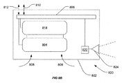
一実施形態では、(i)内部粒子検出システムを有する粒子検出器と、(ii)空気容量を通して放射線ビームを投射する放射線エミッタとを含む粒子検出装置が提供される。この装置は、本明細書全体を通して1型装置と呼ぶことにする。図8Aは1型装置800を示す。装置800は、粒子検出チャンバ804を含む筐体802を含む。検出チャンバ804は、比濁計若しくは遮蔽度検出器のような光学粒子検出器又はイオン化検出器が挙げられるが、これらに限定されない、粒子の存在を検出する任意のタイプのメカニズムを使用することができる。
In one embodiment, a particle detection device is provided that includes (i) a particle detector having an internal particle detection system and (ii) a radiation emitter that projects a radiation beam through an air volume. This device will be referred to as a Type 1 device throughout this specification. FIG. 8A shows a type 1
空気サンプルは、筐体への流入路808を通して、例えば、ダクトを介して、又は筐体802の壁を通るアパーチャを通して直接、検出チャンバ804に導入される。チャンバ804は制御システム806に接続され、制御システム806は、検出チャンバ804の出力信号を処理し、適するアラーム論理を出力信号に適用して、粒子の存在を特定するか、又は処理された出力信号を、チャンバの出力信号を処理するのに適する関連付けられた装置(例えば、ファイアパネル又は中央コントローラ)に渡す電子システムを含む。したがって、制御システム806には、データ通信インタフェース810が提供され、このインタフェースを介して、データを外部装置と交換することができる。ユーザインタフェース(図示せず)を提供することもできる。装置800は、光ビームを放射する光源814及び(任意選択的な)光学システム816も含む。放射線ビーム815は、監視されている容量を横切り、本明細書に記載のように、オープンエリア検出プロセスを実行可能なように放射される。電力は、電力接続812を介して装置800に送られる。この例では、任意選択的な吸気装置818が提供されて、監視中の容量から検出チャンバ804に空気サンプルを引き込む。
The air sample is introduced into the
制御システム806は、予め定義されるイベントの発生時、例えば、外部装置からの信号の受信時若しくは内部チャンバによる粒子の検出時等、又は何らかの他の方式に従って、例えば、周期的に、ランダム、何らかの他の関連イベントの発生時に、光源814をアクティブ化するように構成される。
The
別では、(i)内部粒子検出システムを有する粒子検出器と、(ii)放射された放射線ビームの少なくとも一部を監視するセンサとを含む粒子検出装置が提供される。この装置は、本明細書全体を通して2型装置と呼ぶことにする。
In another, a particle detection device is provided that includes (i) a particle detector having an internal particle detection system and (ii) a sensor that monitors at least a portion of the emitted radiation beam. This device will be referred to as a
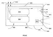
図8Bは2型装置820を示す。装置820は、図8Aの装置800と同様のものであり、共通部分は同じ参照符号で付番される。1型装置と2型装置との主な違いは、光源の代わりに、2型装置820がセンサ822と、(任意選択的な)関連付けられた光学システム824とを含むことである。光センサ822は、監視中の容量の少なくとも一部からの放射線を検出するように構成され、それにより、煙及び/又は火の存在を検出するか、又は検証することができる。好ましい形態では、センサはビデオカメラ等である。装置820は、カメラ822が領域の画像を捕捉して、ビデオ煙及び/又は炎検出を実行可能にするか、又はビーム検出器、能動的なビデオ煙検出システム、又は他のオープンエリア光学煙検出システムの一部を形成する放射線センサであり得るように構成することができる。
FIG. 8B shows a
制御システム806は、1型装置に関連して上述したように周期的に、又は連続してカメラをアクティブ化するように構成される。連続動作の利点は、センサ(センサがカメラである場合)がさらに、監視中の容量のセキュリティカメラとしても動作可能であり、さらに、より詳細に後述するようなビデオ解析プロセスの実行を支援することができることである。
The
更なる実施形態では、(i)内部粒子検出システムを有する粒子検出器と、(ii)空気容量を通して放射線ビームを投射する放射線エミッタと、(iii)放射された放射線ビームの少なくとも一部を監視するセンサとを含む粒子検出装置が提供される。この装置は、本明細書全体を通して3型装置と呼ぶことにする。
In further embodiments, (i) a particle detector having an internal particle detection system, (ii) a radiation emitter that projects a radiation beam through an air volume, and (iii) monitoring at least a portion of the emitted radiation beam. A particle detection device is provided that includes a sensor. This device will be referred to as a
図8Cは3型装置840を示す。装置840は、図8A及び図8Bの装置800及び820と同様でありを含み、共通部分は同じ参照符号で付番される。しかし、3型装置840は、送信器814及びセンサ822の両方を含む。装置820は送信器814及びセンサ822の両方を有するため、反射器を使用して、又は後方散乱ジオメトリにおいて反射器を使用せずに、反射器又はAVSD検出器を使用して単独ビーム検出器として動作することができる。装置802は、他の装置、例えば、単独式光源、カメラ、若しくはセンサ、又は他の1型、2型、若しくは3型装置と協働して、複数の外部検出器を形成することもできる。さらに、上述した各実施形態は、粒子検出器の一部として、放射線ビームからセンサによって取得される情報を解釈する解析手段を含んでもよく、又は粒子検出器から解析手段を除外してもよい。
FIG. 8C shows a
粒子検出システムは、単一の装置又は複数の装置を含み得、粒子検出装置の様々な非限定的な実施形態は、1型、2型、及び3型装置として上述されている。粒子検出システムは、少なくとも1つの粒子検出装置を含むことに加えて、追加の粒子検出器、放射線エミッタ、及び/又はセンサを含むこともできる。粒子検出システムは、粒子検出の少なくとも内部モード及び外部モードが可能なように構成される十分な構成要素を含まなければならない。
The particle detection system may include a single device or multiple devices, and various non-limiting embodiments of the particle detection device are described above as type 1,
場合によっては、粒子検出システムに、粒子検出装置の一部としてであるか、それとも粒子検出装置とは別個の構成要素としてであるかに関係なく、複数の放射線放射構成要素を含むことが望ましい。同様に、場合によっては、複数のロケーションにわたり放射線ビームを監視するか、又は複数の放射線ビームを監視する(例えば、複数のエミッタが使用される場合)複数のセンサを含むことが望ましい。追加又は補足的な構成要素の使用が、バックアップを提供してもよく、又は追加領域をカバーするか、若しくは単一のみのエミッタ若しくはセンサを用いて可能な容量よりも広い容量の空気をカバーするのを支援してもよい。 In some cases, it may be desirable to include a plurality of radiation emitting components in the particle detection system, whether as part of the particle detection device or as a separate component from the particle detection device. Similarly, in some cases it may be desirable to monitor the radiation beam across multiple locations or to include multiple sensors that monitor multiple radiation beams (eg, when multiple emitters are used). Use of additional or supplemental components may provide backup, or cover additional areas, or cover a larger volume of air than is possible with a single emitter or sensor. You may help.
幾つかの実施形態では、粒子検出システムは、追加として反射器を含み得る。反射器は、1型、2型、若しくは3型装置のうちの任意の装置の構成要素として、又は別個の装置の構成要素として含むことができる。反射器は、1つのみの反射面を有してもよく、又は複数の反射面を有してもよい。反射器は、例えば、入射ビームに対して略固定された角度で光ビームを反射するように構成される角反射器であり得る。代替的には、反射器は、入射ビーム又は反射ビームの経路を変更するように操縦可能であり得る。全体を通して引用される「放射線ビーム」という用語は、任意の入射部及び反射部を含め、放射からのビーム全体を包含することが意図される。
In some embodiments, the particle detection system may additionally include a reflector. The reflector can be included as a component of any of the type 1,
本発明は、マルチモード粒子検出システムを使用して空気容量中の粒子を検出する方法にも関する。この方法は、第1の検出モードに従って粒子を検出して、第2の検出モードに従って粒子を検出することを含む。したがって、粒子検出基準のうちの少なくとも1つが、第1の検出モードにおいて満たされる場合、第2の検出モードがアクティブ化される。 The invention also relates to a method for detecting particles in an air volume using a multi-mode particle detection system. The method includes detecting particles according to a first detection mode and detecting particles according to a second detection mode. Accordingly, if at least one of the particle detection criteria is met in the first detection mode, the second detection mode is activated.
上述したように、内部検出モードは、内部検出粒子検出器を有する装置の使用を通して粒子を検出する(上述したように)。外部検出モードは、空気容量を光学的に監視する検出システムの使用を通して粒子を検出する。外部検出モードがアクティブな場合、少なくとも1つの放射線エミッタは、空気容量の少なくとも一部を通して放射線ビームを投射する。次に、センサが、放射線ビームの少なくとも一部から情報を取得する。解析器は、情報を解析して、空気容量中の粒子の存在を検出する。 As described above, the internal detection mode detects particles through the use of a device having an internal detection particle detector (as described above). The external detection mode detects particles through the use of a detection system that optically monitors air volume. When the external detection mode is active, the at least one radiation emitter projects a radiation beam through at least a portion of the air volume. A sensor then acquires information from at least a portion of the radiation beam. The analyzer analyzes the information to detect the presence of particles in the air volume.
この方法では、(i)放射線ビームを投射すること又は(ii)放射線ビームの少なくとも一部についての情報を取得することのうちの少なくとも一方のステップが、粒子検出装置を使用して行われる。すなわち、内部検出モードによる粒子検出に加えて、粒子検出装置は、(i)放射線ビームを投射すること又は(ii)放射線ビームの少なくとも一部についての情報を取得することの何れかにより、外部検出モードによっても粒子を検出する。 In this method, at least one of (i) projecting a radiation beam or (ii) obtaining information about at least a portion of the radiation beam is performed using a particle detector. That is, in addition to particle detection in the internal detection mode, the particle detection device can detect externally by either (i) projecting a radiation beam or (ii) obtaining information about at least a portion of the radiation beam. Particles are also detected by mode.
第1の検出モードは、能動的な検出モードであり、連続して実行してもよく、又はスケジュールに従って周期的に実行してもよい。第1の検出モードは、内部検出メカニズムであってもよく、又は外部検出メカニズムであってもよい。第1の検出モードが内部検出メカニズムである場合、第2の検出モードは外部検出メカニズムである。逆に、第1の検出モードが外部検出メカニズムである場合、第2の検出モードは内部検出メカニズムである。 The first detection mode is an active detection mode and may be executed continuously or periodically according to a schedule. The first detection mode may be an internal detection mechanism or an external detection mechanism. If the first detection mode is an internal detection mechanism, the second detection mode is an external detection mechanism. Conversely, if the first detection mode is an external detection mechanism, the second detection mode is an internal detection mechanism.
一実施形態では、第1の検出モードは、非標準の承認された粒子検出モードであり得、且つ/又は粒子センサからある距離にある粒子を検出することが可能である(すなわち、外部粒子検出メカニズムを使用する)。この場合、第1の検出モードは、粒子検出時に第1のアラーム状態を提供する。この第1のアラーム状態は、第2の粒子検出モードをトリガーするプレアラームであり、第1のアラーム状態のアクティブ化の指示を電子的に通信して(例えば、火災アラーム制御パネル又は監視システムに)、第1の検出モードが粒子を検出したことを示すこともできる。第2の粒子検出モードは、標準の承認された粒子検出モードであってもよく、且つ/又は内部粒子検出メカニズムを使用して粒子を検出することができる。第2の検出モードが粒子を検出する場合、第2のアラーム状態が提供される。この第2のアラーム状態は、粒子の検出を積極的に示し、粒子が検出されたことを示すより高いレベルのアラームをオペレータに提供し得、したがって、第1のアラーム状態を検証するか、若しくはアラーム状態の重要レベルを増大させ、又はアラームをトリガーさせ得る。 In one embodiment, the first detection mode can be a non-standard approved particle detection mode and / or can detect particles at a distance from the particle sensor (ie, external particle detection). Mechanism). In this case, the first detection mode provides a first alarm condition upon particle detection. This first alarm condition is a pre-alarm that triggers a second particle detection mode and electronically communicates an instruction to activate the first alarm condition (eg, to a fire alarm control panel or monitoring system). ), Indicating that the first detection mode has detected particles. The second particle detection mode may be a standard approved particle detection mode and / or an internal particle detection mechanism may be used to detect particles. If the second detection mode detects particles, a second alarm condition is provided. This second alarm condition may positively indicate the detection of particles and provide an operator with a higher level alarm indicating that particles have been detected, thus verifying the first alarm condition or The critical level of an alarm condition can be increased or an alarm can be triggered.
別の態様では、粒子検出の第1の検出モードは、承認された粒子検出モードであり、高感度粒子検出を提供し得、且つ/又は内部粒子検出メカニズムを使用して粒子を検出する。第1の検出モードが粒子を検出する場合、第1のアラーム状態が提供される。このモードが、承認される粒子検出モードであるため、第1のアラーム状態は、粒子の検出を積極的に示し、粒子が検出されたことを示す高レベルアラームをオペレータに提供してもよく、又はアラームをトリガーしてもよい。第1のアラーム状態は、第2の粒子検出モードもトリガーし、第2のモードは、粒子のビデオ検証又は能動的なビデオ検出を提供する。この第2の粒子検出モードは、空気容量中の粒子の位置に関する位置情報を提供する。 In another aspect, the first detection mode of particle detection is an approved particle detection mode, which may provide sensitive particle detection and / or detect particles using an internal particle detection mechanism. A first alarm condition is provided when the first detection mode detects particles. Since this mode is an approved particle detection mode, the first alarm condition may actively indicate the detection of particles and provide the operator with a high level alarm indicating that particles have been detected, Or you may trigger an alarm. The first alarm condition also triggers a second particle detection mode, which provides particle video verification or active video detection. This second particle detection mode provides position information regarding the position of the particles in the air volume.
一実施形態では、第1の検出モードは外部検出モードであり、第2の検出モードは内部検出モードである。この実施形態では、第1の検出モードは、能動的なビデオ検出システム等の外部粒子検出メカニズムを使用し、第2の検出モードは、内部比濁型構成を有するポイント検出器又は吸気粒子検出器等の内部粒子検出システムを使用する。 In one embodiment, the first detection mode is an external detection mode and the second detection mode is an internal detection mode. In this embodiment, the first detection mode uses an external particle detection mechanism such as an active video detection system, and the second detection mode is a point detector or inspiratory particle detector with an internal turbidimetric configuration. Use an internal particle detection system.
アクティブな場合、第1の検出モードの方法は、監視されている空気容量中の少なくとも一部を通して放射線ビームを投射することと、放射線ビームの少なくとも一部から情報を取得することと、放射線ビームの少なくとも一部からの情報を解析して、空気容量中の粒子を検出することとを含む。粒子が検出される場合、第1のアラームがトリガーされる。第1のアラームは、スイッチボード上の光を照明して、粒子が検出されたことを示し得、且つ/又は第1のアラームは、粒子検出イベントが行われたことをオペレータに通知し得る。第1のアラームのトリガーにより、第2の粒子検出モードがアクティブ化される。 When active, the first detection mode method projects a radiation beam through at least a portion of the air volume being monitored, obtains information from at least a portion of the radiation beam, Analyzing information from at least a portion to detect particles in the air volume. If particles are detected, a first alarm is triggered. The first alarm may illuminate the light on the switch board to indicate that particles have been detected, and / or the first alarm may notify the operator that a particle detection event has occurred. The second particle detection mode is activated by the trigger of the first alarm.
アクティブな場合、第2の粒子検出モードは、空気容量の一部を表す空気サンプルを解析して、粒子を検出することと、内部粒子検出器を有する粒子検出装置を使用することと、少なくとも1つの粒子検出基準が満たされる場合、第2のアラームをアクティブ化することとを含む。 When active, the second particle detection mode analyzes an air sample representing a portion of the air volume to detect particles, uses a particle detection device with an internal particle detector, and at least one Activating a second alarm if one particle detection criterion is met.
この方法では、(i)放射線ビームを投射すること又は(ii)放射線ビームの少なくとも一部についての情報を取得することのうちの少なくとも一方は、粒子検出装置を使用して行われる。 In this method, at least one of (i) projecting a radiation beam or (ii) obtaining information about at least a portion of the radiation beam is performed using a particle detector.
必要に応じて、追加の検出モードを追加し得る。システムに応じて、第2のアラーム状態は、第3の粒子検出モードをトリガーすることもできる。第3の粒子検出モードは、別の外部粒子検出方法であり得、例えば、粒子が検出された場所に関連する位置情報を提供する。この情報は、上述したように放射線ビームから推定してもよく、又はビデオ検証モードであってもよい。この場合、第1及び第3の検出モードは、カメラ等の検出システムの同じ物理的構成要素を共有し得る。 Additional detection modes may be added as needed. Depending on the system, the second alarm condition may trigger a third particle detection mode. The third particle detection mode may be another external particle detection method, for example providing position information related to where the particle was detected. This information may be estimated from the radiation beam as described above, or may be in a video verification mode. In this case, the first and third detection modes may share the same physical components of a detection system such as a camera.
この実施形態のシステムを動作させる代替の方法では、第1の粒子検出手段(外部粒子検出手段である)を使用して、第2の粒子検出手段の感度を変更し得る。感度は、状況に応じて増減し得る。例えば、第1の検出モードは、粒子の存在を検出する場合、第2の粒子検出手段を高感度モードにして、粒子の可能な限り早期の確認を達成する信号を出力することができる。代替的には、別個の動作方法では、第1及び第2の検出モードの両方は同時に動作している。第1の検出モードにより粒子が検出されると、第2の検出モードの感度を増大させ得る。 In an alternative method of operating the system of this embodiment, the first particle detection means (which is an external particle detection means) may be used to change the sensitivity of the second particle detection means. Sensitivity can be increased or decreased depending on the situation. For example, in the first detection mode, when detecting the presence of particles, the second particle detection means can be set to a high sensitivity mode to output a signal that achieves confirmation of particles as early as possible. Alternatively, in a separate method of operation, both the first and second detection modes are operating simultaneously. When particles are detected in the first detection mode, the sensitivity of the second detection mode may be increased.
別の実施形態では、第1の検出モードは内部検出モードであり、第2の検出モードは外部検出モードである。この実施形態では、第1の検出モードは、内部比濁型構成を有するポイント検出器又は吸気粒子検出器等の内部粒子検出システムを使用し、第2の検出モードは、能動的なビデオ検出システム等の外部粒子検出メカニズムを使用する。 In another embodiment, the first detection mode is an internal detection mode and the second detection mode is an external detection mode. In this embodiment, the first detection mode uses an internal particle detection system such as a point detector or an inspiratory particle detector with an internal turbidimetric configuration, and the second detection mode is an active video detection system. Use an external particle detection mechanism such as
アクティブな場合、第1の粒子検出モードは、空気容量の一部を表す空気サンプルを解析して、粒子を検出することと、内部粒子検出器を有する粒子検出装置を使用することと、少なくとも1つの粒子検出基準が満たされる場合、第1のアラームをアクティブ化することとを含む。第1のアラームは、粒子の積極的な検出を示し、したがって、アラームがトリガーされ得、且つ/又は粒子が検出されたことをオペレータに通知され得る。第1のアラームは第2の検出モードをアクティブ化する。 When active, the first particle detection mode is to analyze an air sample representing a portion of the air volume to detect particles, to use a particle detector with an internal particle detector, and at least one Activating a first alarm if one particle detection criterion is met. The first alarm indicates an active detection of particles, so the alarm can be triggered and / or the operator can be notified that particles have been detected. The first alarm activates the second detection mode.
アクティブな場合、第2の検出モードの方法は、監視されている空気容量中の少なくとも一部を通して放射線ビームを投射することと、放射線ビームの少なくとも一部から情報を取得することと、放射線ビームの少なくとも一部からの情報を解析して、空気容量中の粒子を検出することとを含む。第2の検出モードは、空気容量中の粒子の位置に関する位置情報を取得するためのものである。この方法では、(i)放射線ビームを投射すること又は(ii)放射線ビームの少なくとも一部についての情報を取得することのうちの少なくとも一方は、粒子検出装置を使用して行われる。 When active, the second detection mode method projects a radiation beam through at least a portion of the air volume being monitored, obtains information from at least a portion of the radiation beam, Analyzing information from at least a portion to detect particles in the air volume. The second detection mode is for acquiring position information related to the position of the particles in the air volume. In this method, at least one of (i) projecting a radiation beam or (ii) obtaining information about at least a portion of the radiation beam is performed using a particle detector.
必要に応じて、追加の検出モードを追加し得る。システムに応じて、第2のアラーム状態は、第3の粒子検出モードをトリガーすることもできる。この場合、第3の粒子検出モードはビデオ検証モードである。この場合、第2及び第3の検出モードは、カメラ等の検出システムの同じ物理的構成要素を共有し得る。 Additional detection modes may be added as needed. Depending on the system, the second alarm condition may trigger a third particle detection mode. In this case, the third particle detection mode is a video verification mode. In this case, the second and third detection modes may share the same physical components of a detection system such as a camera.
更に別の実施形態では、第1又は第2の検出モードのいずれも、アラームシステムとインタフェースせず、その代わり、第1及び第2の検出モードは両方とも、制御パネル(火災制御パネル等)とインタフェースする。 In yet another embodiment, neither the first or second detection mode interfaces with the alarm system; instead, both the first and second detection modes are both control panels (such as fire control panels) and Interface.
粒子検出装置及びシステムは、システムの特定の構成に応じて幾つかの異なる方法に従って動作することができる。粒子検出システムの様々な構成のうちの幾つかを含む幾つかの異なる実施形態について、例において説明する。ここでも、これらの例は可能な構成を示すことが意図され、非限定的に意図される。 The particle detection device and system can operate according to several different methods depending on the particular configuration of the system. Several different embodiments including some of the various configurations of the particle detection system are described in the examples. Again, these examples are intended to illustrate possible configurations and are intended to be non-limiting.
図1は、1型装置(102)と、別個のセンサユニット(105)とを含むマルチモード粒子検出システムの説明のための例を提供する。部屋(101)にマルチモード粒子検出装置(102)が取り付けられる。装置(102)は、内部粒子検出器(図示せず)と、放射線エミッタ(103)とを含む。放射線エミッタは、放射線ビーム(104)を放射することができる。部屋(101)にはセンサ(105)も取り付けられ、センサは、この特定の実施形態では、カメラである。カメラ(105)は、境界線(106a)及び(106b)で示される視野を有する。 FIG. 1 provides an illustrative example of a multi-mode particle detection system that includes a type 1 device (102) and a separate sensor unit (105). A multi-mode particle detector (102) is attached to the room (101). The device (102) includes an internal particle detector (not shown) and a radiation emitter (103). The radiation emitter can emit a radiation beam (104). Also attached to the room (101) is a sensor (105), which in this particular embodiment is a camera. The camera (105) has a field of view indicated by boundaries (106a) and (106b).
この例では、装置(102)の内部検出器を使用する第1の粒子検出モードは、部屋(101)内の空気容量の一部を表す空気サンプルを解析する。粒子検出基準の少なくとも1つが、第1の検出モードで満たされる場合、第1のアラームがトリガーされ、第2の検出モードがアクティブ化される。第1のアラームは、粒子が検出されたことをオペレータに警告し、建物のアラームをアクティブ化し得る。第2の粒子検出モードでは、装置(102)は、装置(102)に統合された放射線エミッタ(103)から放射線ビーム(104)を放射する。放射線ビーム(104)の一部は、カメラ(105)の視野(106a)及び(106b)内に入る。カメラ(105)はビームの画像を捕捉する。この例では、これらの画像は、前方散乱放射線及び/又は後方散乱放射線について解析される。この散乱放射線は、空気容量中の粒子の位置情報を提供する。さらに、ビデオ解析モードをアクティブ化して、粒子の存在の視覚的なビデオ確認をオペレータに提供し得る。第2の検出モード及びビデオ解析モードは、同じカメラを共有し得る。 In this example, the first particle detection mode using the internal detector of the device (102) analyzes an air sample representing a portion of the air volume in the room (101). If at least one of the particle detection criteria is met in the first detection mode, the first alarm is triggered and the second detection mode is activated. The first alarm may alert the operator that particles have been detected and activate the building alarm. In the second particle detection mode, the device (102) emits a radiation beam (104) from a radiation emitter (103) integrated in the device (102). Part of the radiation beam (104) enters the field of view (106a) and (106b) of the camera (105). The camera (105) captures an image of the beam. In this example, these images are analyzed for forward and / or backscattered radiation. This scattered radiation provides the position information of the particles in the air volume. In addition, a video analysis mode may be activated to provide the operator with a visual video confirmation of the presence of particles. The second detection mode and the video analysis mode may share the same camera.
システムを動作させる代替の方法では、第1の粒子検出モードは、装置(102)に統合された放射線エミッタ(103)から放射線ビーム(104)を放射する1型装置(102)を使用する。放射線ビーム(104)の一部は、カメラ(105)の視野(106a)及び(106b)内に入る。カメラ(105)はビームの画像を捕捉し、前方散乱放射線及び/又は後方散乱放射線を解析し、粒子が空気容量中に存在するか否かを判断する。粒子が検出されると、第1のアラームがトリガーされ、第2の検出モードがアクティブ化される。第1のアラームは、この場合、粒子が検出されたことを示す低レベルアラームである。この第2の検出モードでは、装置(102)の内部検出器は、部屋(101)内の空気容量の一部を表す空気サンプルを解析する。粒子検出基準の少なくとも1つが、第2の検出モードにおいて満たされる場合、第2のアラームがトリガーされる。この第2のアラームは、より高い給金性レベルでの粒子の存在の指示をオペレータに提供する優先度のより高いアラームである。この第2のレベルアラームは、建物のアラームをトリガーすることもできる。さらに、第2のアラームは、ビデオ解析に基づいて第3の検出モードをトリガーし得、このモードでは、カメラをアクティブ化させて、粒子の存在の視覚的ビデオ検証をオペレータに提供し得る。第1の検出モード及び第3の検出モードは、同じカメラを共有し得る。 In an alternative method of operating the system, the first particle detection mode uses a type 1 apparatus (102) that emits a radiation beam (104) from a radiation emitter (103) integrated in the apparatus (102). Part of the radiation beam (104) enters the field of view (106a) and (106b) of the camera (105). The camera (105) captures an image of the beam and analyzes the forward and / or backscattered radiation to determine if particles are present in the air volume. When particles are detected, a first alarm is triggered and a second detection mode is activated. The first alarm is in this case a low-level alarm indicating that particles have been detected. In this second detection mode, the internal detector of the device (102) analyzes an air sample representing a portion of the air volume in the room (101). If at least one of the particle detection criteria is met in the second detection mode, a second alarm is triggered. This second alarm is a higher priority alarm that provides the operator with an indication of the presence of particles at a higher payability level. This second level alarm can also trigger a building alarm. Further, the second alarm may trigger a third detection mode based on video analysis, in which the camera may be activated to provide the operator with visual video verification of the presence of particles. The first detection mode and the third detection mode may share the same camera.
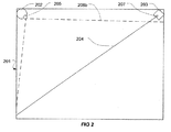
図2は、2型装置(202)と、別個の放射線放射ユニット(203)とを含むマルチモード粒子検出システムの説明のための例を提供する。部屋(201)にマルチモード粒子検出装置(202)及び放射線放射ユニット(203)が取り付けられる。装置(202)は、内部粒子検出器(図示せず)と、センサ(205)とを含み、この実施形態では、センサはカメラである。カメラは、境界線(206a)及び(206b)で示される視野を有する。放射線放射装置(203)は、放射線ビーム(204)を放射することができる放射線エミッタ(207)を有する。
FIG. 2 provides an illustrative example of a multi-mode particle detection system that includes a
この例では、装置(202)の内部検出器を使用する内部粒子検出モードは、部屋(201)内の空気容量の一部を表す空気サンプルを解析する。粒子検出基準の少なくとも1つが、この検出モードで満たされる場合、アラームがトリガーされ、適切な場合、更なる検出モードがアクティブ化される。 In this example, the internal particle detection mode using the internal detector of the device (202) analyzes an air sample that represents a portion of the air volume in the room (201). If at least one of the particle detection criteria is met in this detection mode, an alarm is triggered and, if appropriate, a further detection mode is activated.
外部粒子検出モードは、放射線ビーム(204)を放射線エミッタ(207)から放射する放射線放射ユニット(203)を使用して動作可能である。放射線ビーム(204)の一部は、カメラ(205)の視野(206a)及び(206b)内に入る。カメラ(205)は装置(202)に統合される。カメラ(205)は、放射線ビーム(204)の画像を捕捉する。この例では、これらの画像は、前方散乱放射線及び/又は後方散乱放射線について解析される。この散乱放射線は、空気容量中の粒子の位置情報を提供する。外部粒子検出モードによって粒子が検出されると、アラームがトリガーされ、適切な場合、更なる検出モードがアクティブ化される。 The external particle detection mode is operable using a radiation emitting unit (203) that emits a radiation beam (204) from a radiation emitter (207). A portion of the radiation beam (204) enters the field of view (206a) and (206b) of the camera (205). The camera (205) is integrated into the device (202). The camera (205) captures an image of the radiation beam (204). In this example, these images are analyzed for forward and / or backscattered radiation. This scattered radiation provides the position information of the particles in the air volume. When a particle is detected by the external particle detection mode, an alarm is triggered and, if appropriate, a further detection mode is activated.
図1のシステムと同様に、図2のシステムは、(i)第1の検出モードが内部検出モードであり、第2の検出モードが外部検出モードであるか、又は(ii)第1の検出モードが外部検出モードであり、第2の検出モードが内部検出モードであるように動作することができる。さらに、システムは、上述したように、第3の検出モードを含み得る。 Similar to the system of FIG. 1, the system of FIG. 2 is either (i) the first detection mode is the internal detection mode and the second detection mode is the external detection mode, or (ii) the first detection mode. It is possible to operate so that the mode is the external detection mode and the second detection mode is the internal detection mode. Further, the system may include a third detection mode as described above.
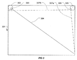
図3は、1型装置(302)と、2型装置(305)とを含むマルチモード粒子検出システムの説明のための例を提供する。部屋(301)に、第1の粒子検出装置(302)及び第2の粒子検出装置(305)という2つのマルチモード粒子検出装置が取り付けられる。第1の粒子検出装置(302)は、内部粒子検出器(図示せず)と、放射線エミッタ(303)とを含む。放射線エミッタは、放射線ビーム(304)を放射することができる。第2の粒子検出装置(305)は、内部粒子検出器(図示せず)と、センサ(306)とを含み、この実施形態では、センサはカメラである。カメラは、境界線(307a)及び(307b)で示される視野を有する。
FIG. 3 provides an illustrative example of a multi-mode particle detection system that includes a type 1 device (302) and a
この例では、第1の粒子検出モードは、第1の粒子検出装置(302)及び第2の粒子検出装置(305)の内部検出器を使用して動作する。これらの内部検出器は、部屋(301)内の空気容量の一部を表す空気サンプルを解析する。粒子検出基準の少なくとも1つが、第1の検出モードにおいて、第1の粒子検出装置(302)又は第2の粒子検出装置(305)の何れかによって満たされる場合、第1のアラームがトリガーされ、第2の検出モードがアクティブ化される。このモードでは、第1の検出装置(302)は、装置(302)に統合された放射線エミッタ(303)から放射線ビーム(304)を放射する。第2の検出装置(305)はセンサ(306)を含み、この場合、センサは、(307a)及び(307b)によって画定される視野を有するカメラである。カメラ(306)は、第2の検出装置(305)に統合される。放射線ビーム(304)の一部は、カメラ(306)の視野(307a)及び(307b)内に入る。カメラ(306)は、放射線ビーム(304)の画像を捕捉する。この例では、これらの画像は、前方散乱放射線及び/又は後方散乱放射線について解析される。この散乱放射線は、空気容量中の粒子の位置情報を提供する。 In this example, the first particle detection mode operates using the internal detectors of the first particle detection device (302) and the second particle detection device (305). These internal detectors analyze an air sample that represents a portion of the air volume in the room (301). If at least one of the particle detection criteria is met by either the first particle detection device (302) or the second particle detection device (305) in the first detection mode, a first alarm is triggered; The second detection mode is activated. In this mode, the first detection device (302) emits a radiation beam (304) from a radiation emitter (303) integrated in the device (302). The second detection device (305) includes a sensor (306), where the sensor is a camera having a field of view defined by (307a) and (307b). The camera (306) is integrated into the second detection device (305). Part of the radiation beam (304) falls within the field of view (307a) and (307b) of the camera (306). The camera (306) captures an image of the radiation beam (304). In this example, these images are analyzed for forward and / or backscattered radiation. This scattered radiation provides the position information of the particles in the air volume.
先のように、図3のシステムは、(i)第1の検出モードが内部検出モードであり、第2の検出モードが外部検出モードであるか、又は(ii)第1の検出モードが外部検出モードであり、第2の検出モードが内部検出モードであるように動作することができる。さらに、システムは、上述したように、第3の検出モードを含み得る。 As described above, in the system of FIG. 3, (i) the first detection mode is the internal detection mode and the second detection mode is the external detection mode, or (ii) the first detection mode is the external detection mode. The detection mode can be operated so that the second detection mode is the internal detection mode. Further, the system may include a third detection mode as described above.
図4は、3型装置(402)と、反射器(405)とを含むマルチモード粒子検出システムの説明のための例を提供する。部屋(401)にマルチモード粒子検出装置(402)が取り付けられる。装置(402)は、内部粒子検出器(図示せず)と、放射線エミッタ(403)と、センサ(404)とを含み、この特定の実施形態では、センサはカメラである。エミッタ(403)及びカメラ(404)は両方とも、装置(402)に統合される。カメラ(404)は、境界線(407a)及び(407b)で示される視野を有する。部屋(401)は反射器(405)も含む。放射線エミッタ(403)は放射線ビーム(406)を放射し、これは、ミラーで反射され、カメラ(404)の視野(407a)及び(407b)を通る。
FIG. 4 provides an illustrative example of a multi-mode particle detection system that includes a
この例では、内部粒子検出モードは、装置(402)の内部検出器を使用して、部屋(401)内の空気容量の一部を表す空気サンプルを解析する。粒子検出基準の少なくとも1つが、内部検出モードで満たされる場合、アラームがトリガーされ、アラームのトリガーにより、追加の検出モードをアクティブ化し得る(例えば、これが第1の検出モードである場合、粒子が検出されると、第2の検出モードがトリガーされる)。 In this example, the internal particle detection mode uses an internal detector of the device (402) to analyze an air sample that represents a portion of the air volume in the room (401). If at least one of the particle detection criteria is met in the internal detection mode, an alarm is triggered and the alarm trigger may activate an additional detection mode (eg, if this is the first detection mode, the particle is detected The second detection mode is triggered).
粒子検出システムは、外部粒子検出モードも含む。装置(402)は、装置(402)に統合された放射線エミッタ(403)から放射線ビーム(406)を放射する。装置(402)はセンサ(404)も含み、この場合、センサは、(407a)及び(407b)によって画定される視野を有するカメラである。カメラ(404)は装置(402)に統合される。放射線ビーム(406)は、部屋(401)を通して投射され、反射器(405)を使用して反射され、カメラ(404)の視野(407a)及び(407b)を通る。カメラ(404)は、放射線ビーム(406)の画像を捕捉する。この例では、これらの画像は、前方散乱放射線及び/又は後方散乱放射線について解析される。この散乱放射線は、空気容量中の粒子の位置情報を提供する。粒子が検出される場合、アラームがトリガーされ、アラームのトリガーにより、追加の検出モードをアクティブ化し得る(上述したように)。 The particle detection system also includes an external particle detection mode. The device (402) emits a radiation beam (406) from a radiation emitter (403) integrated in the device (402). The apparatus (402) also includes a sensor (404), where the sensor is a camera having a field of view defined by (407a) and (407b). The camera (404) is integrated into the device (402). The radiation beam (406) is projected through the room (401), reflected using the reflector (405), and passes through the fields of view (407a) and (407b) of the camera (404). The camera (404) captures an image of the radiation beam (406). In this example, these images are analyzed for forward and / or backscattered radiation. This scattered radiation provides the position information of the particles in the air volume. If particles are detected, an alarm is triggered, which can activate additional detection modes (as described above).
先の例と同様に、内部粒子検出モード又は外部粒子検出モードの何れかが第1又は第2のモードであり得ることが一般に理解される。ビデオ検証等の追加の粒子検出モードを利用してもよいことも一般に理解される。 As with the previous example, it is generally understood that either the internal particle detection mode or the external particle detection mode can be the first or second mode. It is also generally understood that additional particle detection modes such as video verification may be utilized.
図5は、変更された1型装置(504)、2型装置(503)、及び変更された3型装置(502)である3つのマルチモード検出器を含む粒子検出システムの説明のための例を提供する。部屋(501)に、第1の粒子検出装置(502)、第2の粒子検出装置(503)、及び第3の粒子検出装置(504)である3つのマルチモード粒子検出装置が取り付けられる。第1の粒子検出装置(502)は、内部粒子検出器(図示せず)と、幾つかの放射線エミッタ(505a)及び(505b)と、幾つかのセンサ(507a)及び(507b)とを含み、この実施形態では、センサはカメラである。放射される各放射線は、放射線ビーム(506a)及び(506b)をそれぞれ放射する。各カメラはそれぞれ、点線(508a)及び(508b)並びに(509c)及び(509b)で示される視野を有する。第2の粒子検出装置(504)は、内部粒子検出器(図示せず)と、幾つかの放射線エミッタ(510a)及び(510b)とを含む。各放射線エミッタは、線(511a)及び(511b)で示される放射線をそれぞれ放射する。第3の粒子検出装置(503)もシステムに含まれる。第3の粒子検出装置は、内部粒子検出器(図示せず)と、センサ(512)とを含み、この実施形態では、センサはカメラである。カメラ(512)は、(513a)及び(513b)で示される視野を有する。この例では、放射線ビーム(506a)及び(506b)はカメラ(512)の視野を通り、放射線ビーム(511a)はカメラ(507b)の視野を通り、放射線ビーム(511b)はカメラ(507a)の視野を通る。
FIG. 5 is an illustrative example of a particle detection system that includes three multi-mode detectors, a modified type 1 device (504), a
この例では、内部粒子検出モードは、第1の粒子検出装置(502)、第2の粒子検出装置(503)、及び第3の粒子検出装置(504)の内部検出器を使用して、部屋(501)内の空気容量の一部を表す空気サンプルを解析する。粒子検出基準の少なくとも1つが、第1の粒子検出装置(502)、第2の粒子検出装置(503)、又は第3の粒子検出装置(504)によって満たされる場合、アラームがトリガーされ、更なる粒子検出モードをアクティブ化し得る。 In this example, the internal particle detection mode is performed using the internal detectors of the first particle detection device (502), the second particle detection device (503), and the third particle detection device (504). Analyze an air sample representing a portion of the air volume within (501). If at least one of the particle detection criteria is met by the first particle detection device (502), the second particle detection device (503), or the third particle detection device (504), an alarm is triggered and further A particle detection mode may be activated.
外部検出モードでは、第1の検出装置(502)は、放射線エミッタ(505a)及び(505b)から放射線ビーム(506a)及び(506b)をそれぞれ放射し、これらのエミッタは第1の装置(502)に統合される。さらに、このモードでは、第3の検出装置(504)は、放射線エミッタ(510a)及び(510b)から放射線ビーム(511a)及び(511b)をそれぞれ放射し、これらのエミッタは第3の装置(504)に統合される。第1の検出装置(502)はセンサ(507a)及び(507b)を含み、この場合、これらのセンサは、(508a)及び(508b)並びに(509a)及び(509b)によって画定される視野を有するカメラである。カメラ(507a)及び(507b)は、第1の検出装置(502)に統合される。放射線ビーム(511a)の一部は、カメラ(507b)の視野内に入る。放射線ビーム(511b)の一部は、カメラ(507a)の視野内に入る。カメラは、各放射線ビームの画像を捕捉する。第2の検出装置(503)はセンサ(512)を含み、この場合、センサは、(513a)及び(513b)によって画定される視野を有するカメラである。カメラ(512)は、第2の検出装置(503)に統合される。放射線ビーム(506a)及び(506b)の一部は、カメラ(512)の視野内に入る。カメラは、放射線ビーム(506a)及び(506b)のそれぞれの画像を捕捉する。この例では、これらの画像は、前方散乱放射線及び/又は後方散乱放射線について解析される。この散乱放射線は、空気容量中の粒子の位置情報を提供する。粒子が検出される場合、アラームがトリガーされ、アラームのトリガーにより、追加の検出モードをアクティブ化し得る(上述したように)。 In the external detection mode, the first detection device (502) emits radiation beams (506a) and (506b) from the radiation emitters (505a) and (505b), respectively, which emitters are the first device (502). Integrated into. Further, in this mode, the third detection device (504) emits radiation beams (511a) and (511b) from the radiation emitters (510a) and (510b), respectively, and these emitters emit the third device (504). ). The first detection device (502) includes sensors (507a) and (507b), where these sensors have a field of view defined by (508a) and (508b) and (509a) and (509b). It is a camera. The cameras (507a) and (507b) are integrated into the first detection device (502). Part of the radiation beam (511a) falls within the field of view of the camera (507b). Part of the radiation beam (511b) falls within the field of view of the camera (507a). The camera captures an image of each radiation beam. The second detection device (503) includes a sensor (512), where the sensor is a camera having a field of view defined by (513a) and (513b). The camera (512) is integrated into the second detection device (503). Some of the radiation beams (506a) and (506b) fall within the field of view of the camera (512). The camera captures respective images of the radiation beams (506a) and (506b). In this example, these images are analyzed for forward and / or backscattered radiation. This scattered radiation provides the position information of the particles in the air volume. If particles are detected, an alarm is triggered, which can activate additional detection modes (as described above).
上記実施形態では、外部粒子検出モードの説明のための例は、静的、線形、又はコリメートビームを使用する。本発明は、この方法に限定されるものと見なされるべきではない。本発明の実施形態は、鉛筆様ビームではなく、2Dシート、円柱形、又は他の空間パターン等のより複雑な形状を有する放射線ビームを生成するソースを用いることができる。そのような検出モードの一実施態様は、図42、図43、及び図45に関連して米国特許出願第2011/0058167号明細書に記載されている。他の例では、レーザビームは、ホログラムを通り、シート若しくはパターンを生成するか、又はカメラのシャッタが開かれている間にレーザを素早く掃引して、シートを生成することができる。他の技法も可能である。 In the above embodiment, the illustrative example of the external particle detection mode uses a static, linear, or collimated beam. The present invention should not be regarded as limited to this method. Embodiments of the present invention can use a source that produces a radiation beam having a more complex shape, such as a 2D sheet, cylinder, or other spatial pattern, rather than a pencil-like beam. One embodiment of such a detection mode is described in US patent application 2011/0058167 in connection with FIGS. 42, 43, and 45. In other examples, the laser beam can pass through the hologram to produce a sheet or pattern, or the laser can be quickly swept while the camera shutter is open to produce a sheet. Other techniques are possible.
先の例と同様に、内部粒子検出モード又は外部粒子検出モードの何れかが第1又は第2のモードであり得ることが一般に理解される。ビデオ検証等の追加の粒子検出モードを利用してもよいことも一般に理解される。 As with the previous example, it is generally understood that either the internal particle detection mode or the external particle detection mode can be the first or second mode. It is also generally understood that additional particle detection modes such as video verification may be utilized.
図6及び図7は、図1及び図2に示されるものと同様の構成をそれぞれ提供する。これらの図を除き、外部粒子検出の方法はレーザビームの減衰の測定を通しての方法である。 6 and 7 provide a configuration similar to that shown in FIGS. 1 and 2, respectively. Except for these figures, the method of external particle detection is through the measurement of laser beam attenuation.
特に、図6は、1型装置(602)と、センサ(605)とを含む粒子検出システムを含む部屋(601)の一例を提供する。粒子検出装置(602)は、粒子を検出する内部センサ(図示せず)と、装置に統合される放射線エミッタ(603)とを有する。センサ(605)は、カメラ又はフォトダイオード等の光検出センサであり得るが、この場合、センサはカメラである。 In particular, FIG. 6 provides an example of a room (601) that includes a particle detection system that includes a type 1 device (602) and a sensor (605). The particle detector (602) has an internal sensor (not shown) for detecting particles and a radiation emitter (603) integrated into the device. The sensor (605) can be a light detection sensor such as a camera or a photodiode, in which case the sensor is a camera.
内部粒子検出モードは、装置(602)の内部センサを使用する。外部粒子検出モードは、装置(602)の光エミッタ(603)と、カメラ(605)との組み合わせを使用する。光エミッタ(603)は、空気容量を通して放射線ビーム(604)を投射する。カメラ(605)は、受け取るビーム(604)の強度を測定する。粒子の存在は、ビームの強度を減少させ、これは粒子の存在を示す。 The internal particle detection mode uses the internal sensor of the device (602). The external particle detection mode uses a combination of the light emitter (603) of the device (602) and the camera (605). The light emitter (603) projects a radiation beam (604) through the air volume. The camera (605) measures the intensity of the received beam (604). The presence of particles reduces the intensity of the beam, which indicates the presence of particles.
図7は、略同じように動作する、図6に示される構成に対する代替の構成を提供する。基本的に、図7は、2型装置(702)と、放射線エミッタ(703)とを含む粒子検出システムを含む部屋(701)の一例を提供する。粒子検出装置(702)は、粒子を検出する内部センサ(図示せず)と、装置に統合されるカメラ(705)とを有する。
FIG. 7 provides an alternative configuration to the configuration shown in FIG. 6 that operates in substantially the same manner. Basically, FIG. 7 provides an example of a room (701) that includes a particle detection system that includes a
本発明者等は、図8Bに示されるような2型装置又はセキュリティカメラ若しくは専用画像捕捉システム等の別の撮像装置の何れかを使用して、アラートの検証及び他の煙及び/又は火検出プロセスを提供して、誤検出状況を最小に抑えることができることも識別した。この点に関して、第1の動作モードでは、本明細書に記載されるような粒子検出システム又は任意の従来の粒子検出システムを使用して、初期粒子検出プロセスを実行することができる。第1の閾値レベル、例えば、プレアラームレベルで粒子が検出されると、ビデオ検証プロセスを開始することができる。ビデオ検証プロセスは、監視されている容量の複数の画像の解析を実行して、捕捉画像での煙又は火の存在を特定することを含むことができる。様々なビデオ解析技法が、画像での煙又は火の存在の特定に使用されることが分かっており、したがって、これについては本明細書において詳述しない。そのようなビデオ解析技法は通常、煙及び/又は火と同等の視覚的特性を有する画像内の特徴を検出する画像の解析並びに/或いは画像内の煙及び/又は火の程度を特定することを含む。
We use either a
幾つかの実施形態では、シーンのビデオ画像を連続して捕捉することができ、好ましくは、ビデオ解析も連続して実行される。そのようなシステムでは、第1の閾値レベル、例えば、プレアラームレベルで粒子が検出されると、ビデオ解析の現在の状態又は続く状態が使用される。これには、ビデオ解析システムが、粒子の検出前に捕捉されたビデオ画像及び他のデータへのアクセスを有するという利点があり、これはこの性能を支援することができる。 In some embodiments, video images of the scene can be captured continuously, and preferably video analysis is also performed continuously. In such a system, if a particle is detected at a first threshold level, eg, a pre-alarm level, the current state of video analysis or the subsequent state is used. This has the advantage that the video analysis system has access to video images and other data captured prior to particle detection, which can support this performance.
連続ビデオ捕捉及び解析の他の利点は、ビデオ解析を連続して実行し得、任意の1型、2型、又は3型装置に先だって粒子を検出し得ることである。この場合、ビデオ解析は、アラームをトリガーするように構成することができる。1型、2型、又は3型装置が続けて粒子を検出する場合、アラームの状態を、本明細書の他のどこかで説明されるように、検証済みアラームに変更するか、又は検出直後に検証済みとみなすことができる。
Another advantage of continuous video capture and analysis is that video analysis can be performed continuously and particles can be detected prior to any Type 1,
より高度な実施形態では、ビデオ解析検出の1つ又は複数のチャネルと、1つ又は複数の1型、2型、又は3型検出器との組み合わせは、ダブルノックのように動作し得る。この場合、アラームをトリガーするには、2つ又は3つ以上の検出器が、ユーザ定義可能な時間枠内で粒子を検出していなければならない。好ましくは、定義された時間枠内で粒子を検出した2つ(又は3つ以上)の検出器は、同じ空気容量を監視しているが、場合によっては、関連するロケーションを監視し得る。これらの例では、ビデオ解析システムは、連続して実行してもよく、又は1型、2型、又は3型検出器のうちの1つ又は複数が粒子を検出した場合、画像の捕捉又は解析を開始してもよい。
In more advanced embodiments, the combination of one or more channels of video analysis detection and one or more type 1,
一次粒子検出システムによって検出されるアラート状況が、ビデオ検証システムによって検証される場合、粒子検出出力に割り当てられるアラートレベルを上昇させることができるか、又は検出されたイベントが検証されたことの指示をシステムのユーザに与えることができる。さらに、空気容量の画像をシステムのユーザに提示して、人間による検証を支援することができる。これらの画像は、素早い手動検証の支援として、ビデオ検証システムによって画像内のどこに、煙及び/又は火が存在すると特定されたかの指示を含むように提示することができる。 If the alert status detected by the primary particle detection system is verified by the video verification system, the alert level assigned to the particle detection output can be increased, or an indication that the detected event has been verified. Can be given to users of the system. Furthermore, an air volume image can be presented to the system user to assist human verification. These images can be presented to include an indication of where in the image the smoke and / or fire has been identified as present as an aid to quick manual verification.
代替の動作モードでは、ビデオ解析プロセスを連続して(又は必要に応じて所定の期間にわたり)実行することができ、捕捉画像が煙及び/又は火の画像を含むと判断される場合、他の煙又は火検知システムの動作をトリガーするか、又は変更することができる。例えば、センサの感度を、例えば早期検出が優先されるように閾値検知レベル又はアラーム遅延時間を低減することにより、増大することができる。 In an alternative mode of operation, the video analysis process can be performed continuously (or over a predetermined period of time if necessary), and if it is determined that the captured image includes smoke and / or fire images, other The operation of the smoke or fire detection system can be triggered or changed. For example, the sensitivity of the sensor can be increased, for example, by reducing the threshold detection level or alarm delay time so that early detection is prioritized.
図9は、複数の部屋を含む建物900の間取り図である。各部屋は、各カメラによって監視されるゾーンに属するものとして示される。この点に関して、ゾーン1はカメラ901によって監視され、ゾーン2はカメラ902によって監視され、ゾーン3はカメラ903によって監視され、ゾーン4はカメラ904によって監視され、ゾーン5はカメラ905によって監視され、ゾーン6はカメラ906によって監視され、ゾーン7はカメラ907によって監視され、ゾーンnはカメラ908によって監視される。
FIG. 9 is a floor plan of a
各ゾーンは粒子検出器910.1〜910.nも含む。粒子検出器910.1〜910.nは、ポイント検出器、吸気検出器、ビーム検出器、上述したオープンエリア能動的ビデオ検出器、又は本明細書において他のどこかで説明される1型、2型、又は3型に従って作られる検出器を含む任意のタイプのものであり得る。粒子検出器910.1〜910.nはそれぞれ、FACP又は中央コントローラ912の形態の建物煙アラームシステムに接続され、そのシステムでアドレスを有するものとして個々に識別し得、それにより、建物900内の火検出ロケーションを火災アラームシステムによって特定することができる。火災アラームシステム内の煙検出のロケーションは、任意の様式で、例えば、本出願人によって出願された豪州特許出願第2012904516号明細書、同第2012904854号明細書、及び同第2013200353号明細書の何れかに記載される何れか1つの技法を使用して特定することができる。これらの技法は特に、吸気粒子検出システムで使用されるように構成される。ポイント検出器の場合、検出のロケーションは容易に特定される。各カメラ901〜908は、中央制御システム912に接続される。中央制御システム912はビデオ解析システムであり、複数のカメラからビデオフィードを受信して解析する。中央コントローラは、ビデオフィードを記憶し、リアルタイムで、又はイベントが検出される際にオンデマンドで中央監視ステーションに送信することもできる。コントローラ912は、通信チャネルを介して中央監視ステーション(CMS)914に接続され、CMSにおいて、火関連及びセキュリティ関連の両方のアラーム状況を監視することができる。代替の実施形態では、コントローラ912及びFACPの機能は、単一の装置に結合することができる。中央監視ステーション914の機能をコントローラ912において実行することもできる。同様に、カメラ、他のセキュリティシステム(図示せず)、及び火及び/又は煙検出器は、全ての監視及び解析(すなわち、コントローラ912及びFACPの機能)を直接実行するリモートCMSに直接接続することができる。
Each zone has a particle detector 910.1-910. Also includes n. Particle detector 910.1-910. n is made according to point detector, inspiration detector, beam detector, open area active video detector as described above, type 1,
これより、図9の建物900のゾーン2で火災が始まる状況を考える。この場合、部屋内に配置されるセンサシステム910.2が、噴煙911内の煙粒子の存在を検出し、アラート信号を火災アラーム制御パネル(FACP)に送信する。そのようなシステムで従来通りのように、センサ910.2の出力信号は、検出された粒子のレベル又は検出器のアラーム論理に従って決定されるアラーム状態を示すことができる。火災アラーム制御パネルは、中央コントローラ912を介してこのアラートデータを中央監視ステーション914に通信し、ステーションにおいて、スタッフは建物90内の状況を監視することができる。システムはビデオ検証機能を含むため、検出器910.2によってゾーン2において粒子が検出されると、カメラ902を使用するビデオ検証がアクティブ化される。カメラ902は、画像の捕捉(先に画像を捕捉していなかった場合)又は画像の解析の何れかを開始して、煙が画像から存在すると検証することができるか否かを判断する。カメラ902からのビデオフィードは、中央コントローラ912に提供される。中央コントローラ912は、カメラ902によって捕捉される一連のフレームに対してビデオ解析を実行して、画像内に、カメラ902の視野902.1内の煙又は炎の存在を示す視覚的特徴があるか否かを判断する。このビデオ解析は、コントローラ912又は中央監視ステーション914の何れかで実行することができる。解析が中央監視ステーション914で実行される場合、解析のために、恐らくは圧縮された形態のビデオ画像を現場コントローラ912から中央監視ステーション914に送信する必要がある。カメラ902によって捕捉される画像で煙又は火災が検出されると、中央監視ステーション914で実行中のアラートシステムが、煙検出器910.2によって示されたアラート状況がビデオ解析システムによって検証されたことを示すように、その出力を変更することができる。この検証から、ユーザは、誤検出の可能性が低いことを推測することができる。
Consider the situation where a fire starts in
中央監視ステーション914を監視中のユーザに、火災又は煙アラームが検証されたことを示すことにより、そのアラームの重要性レベルが上昇する。したがって、システムを監視している人物が、アラートに対してより迅速に行動することが促進される。図10及び図11は、本発明の実施形態により中央監視ステーションに提供することができる2つの代替のインタフェースを示す。まず図10を参照すると、インタフェースは複数のビデオ表示パネル1001、1002、1003、及び1004を含み、各パネルは、監視されている建物900内の異なるカメラから捕捉される画像を表示する。大きな表示枠1001が、アラートが発生したシーンを視覚的に検査できるように、監視システムのユーザにロケーションのより近いビューを与えるために提供される。より小さな表示枠1002〜1004は、適切な方式に従って循環し得るか、又は代替的には、対応するゾーンでのアラートレベルに従った優先順位でランク付け得る。インタフェース1000の下部はイベントリスト1007を含む。イベントごとに、イベントデータが表示され、システムのユーザに、特定の応答行動を実行する一連のボタン1009が提供される。イベントごとに、以下のデータが表示される:イベントの数値リストであるイベント番号1012、後にアクセスするためにログ記録されたイベントデータのインデックス付けに使用されるイベントのシステム全体で一意の識別子である「イベントID」1014、イベントの性質を説明するイベント説明1016、イベントの優先度ランクであるイベントレベル1018、イベントのステータス1020のインジケータ、例えば、イベントのステータスがアラームであるか、それとも誤りであるか、それとも他の特定のタイプのアラートであるかのインジケータ、一連の行動ボタン1022.1、1022.2、1022.3。
By indicating to a user monitoring
本例でのイベント番号5は、最高アラートステータスを有し、ここでより詳細に説明する。イベント番号5は、煙がゾーン2で検出されたことの指示である。この例では、煙は、アラームを発すべきことを示すレベルで、粒子検出器910.2によって検出されている。ステータス列において、ビデオ解析システムがカメラ902の出力を解析し、煙及び火が存在すると判断したため、イベントは「アラーム検証済み」として示される。検証をシステムのユーザに示すために、インタフェースは、イベント番号5に対応するステータスボックスを強調表示し、アラームが「検証済み」であることをテキスト形態で示している。さらに気付かれるように、ゾーン2の画像は、ビデオ解析システムによって検出された煙及び火のロケーションの視覚的インジケータ1008を含む。これに関して、ビデオ解析システムは、カメラ902によって捕捉された一連の画像の解析を実行しており、煙を表すと判断された画像内の領域の周りに境界又はエッジを示している。さらに、画像1010内のゾーンの指示は、火災を生じさせている炎を表すように見えるように示される。
Event number 5 in this example has the highest alert status and will now be described in more detail. Event number 5 is an indication that smoke has been detected in
図11は、図10のインタフェースに対する代替のインタフェースを示し、これらの2つの図のインタフェースの違いは、イベント番号5のステータスが「検証」されたことを単に示すのではなく、図11のインタフェースが、イベントのアラームレベル及び検証レベルに従って各イベントをイベントリストに並べることだけである。これは、システム内のその他のイベントと比較して、イベント番号5により大きな優先度を与えるべきであることを更に強調表示する。 FIG. 11 shows an alternative interface to the interface of FIG. 10, and the difference between the interfaces of these two diagrams does not simply indicate that the status of event number 5 has been “verified”, but the interface of FIG. Simply list each event in the event list according to the alarm level and verification level of the event. This further highlights that event number 5 should be given a higher priority compared to other events in the system.
イベントが、自動ビデオ検証システムによって検出されて検証されると、イベントに応答して行動をとると判断するのは、システムの人間ユーザによる。人は、イベントの却下(1022.2)を選び得るか、イベントに対応するビデオフィードの閲覧(ボタン1022.1)を選び、更に調査をし得るか、又は警察、消防隊、若しくは他の適切な緊急事態対応サービスへの通報により、外部アラームを発することを選び得る。これは、示される閲覧ボタン(1022.1)、却下ボタン(1022.2)、又は通報ボタン(1022.3)を使用して、図10及び図11のインタフェースを使用して実行することができる。 When an event is detected and verified by the automated video verification system, it is up to the human user of the system to determine to take action in response to the event. A person may choose to reject the event (1022.2), or choose to view the video feed corresponding to the event (button 1022.1) for further investigation, or police, fire brigade, or other appropriate You may choose to issue an external alarm by reporting to an emergency response service. This can be done using the interface of FIGS. 10 and 11 using the browse button (1022.1), reject button (1022.2), or notification button (1022.3) shown. .
本発明の更なる実施形態では、ビデオ解析システムが、保留中のイベントの調査においてユーザを更に支援することが有利である。この点に関して、システムのユーザは、例えば、イベントの発端となった場所を特定するか、又はイベントの真の原因が何であるか、例えば、何かに火が付いているか、又は何に火が燃え移る危険があり、煙検出イベントの原因となっているかを特定することにより、アラートの原因を調査したいことがある。そのような情報は、アラート状況に対する対応戦略を決定するに当たって特に有益であることができる。例えば、厳密に何に火が付いているかがわかっている場合、適切な鎮圧戦略を実施することができる。さらに、火を囲んでいる任意の物を視覚的に検査して、どのレベルの対応が必要かを判断することができる。例えば、重要な機器又は危険若しくは可燃性の物品が、火がある上のエリアの周囲にある場合、より迅速な対応又は全避難が必要であり得、一方、火が比較的開けたエリア又は不燃性の物品があるエリアで検出される場合、より遅い(又は少なくとも異なる)対応が無難であり得る。 In a further embodiment of the invention, it is advantageous that the video analysis system further assists the user in investigating pending events. In this regard, the user of the system may, for example, identify where the event originated, or what is the real cause of the event, for example, something is on fire or what is on fire You may want to investigate the cause of the alert by identifying whether there is a risk of burning out and causing the smoke detection event. Such information can be particularly useful in determining response strategies for alert situations. For example, if you know exactly what is on fire, you can implement an appropriate suppression strategy. In addition, any object surrounding the fire can be visually inspected to determine what level of response is required. For example, if critical equipment or dangerous or flammable items are around the upper area where there is a fire, a quicker response or total evacuation may be necessary, while the fire is relatively open area or non-flammable If a sex item is detected in an area, a slower (or at least different) response may be safe.
検査プロセスを支援するために、中央監視ステーションに、1つ又は複数のカメラ及び状況センサからのアラーム出力を解析し、イベントの原因又は性質について推奨される調査の順序についてユーザに推奨するソフトウェアを提供することができる。例えば、ソフトウェアシステムは、監視されている設備内の部屋及び物品の相対位置についてのマップ又は他の地理的データを記憶し、どの検出器がアラート状況を検知したかを表すデータを使用して、火の発端となった可能性が高い中央ポイント又は調査優先度を決定することができる。例えば、図10及び図11では、検証済みアラームがゾーン2で検知されており、未検証のアラームがゾーン3で検知されている。プレアラームもゾーン1で検知されている。炎の存在(図10において1010で示される)の検証が可能ではない状況では、中央監視ステーションは、ゾーン2、次にゾーン3、その後にゾーン1、その後にゾーンNの順序で、他のゾーンでの手動解析順を推奨する。これは、ゾーン2、3、及び1の受信アラートレベルと、ゾーン2、3、N、及び7の出入り口への近さと、ゾーン1がそれらのゾーン間の通路であることとに基づく。他の実施形態では、他の要因が、検査順の決定に役割を果たすことができ、例えば、建物の空調リターンダクトが位置920に配置される場合、検出器9140.12の出力は、他の検出ポイントよりも頻繁に煙を示す傾向を有するため、全ての「上流」検出器よりも低い優先度のものとして扱うことができる。
To assist the inspection process, the central monitoring station is provided with software that analyzes the alarm output from one or more cameras and status sensors and recommends the user with a recommended order of investigation for the cause or nature of the event can do. For example, the software system stores a map or other geographical data about the relative location of rooms and items in the facility being monitored, and uses data representing which detector has detected an alert condition, A central point or survey priority that is likely to be the start of a fire can be determined. For example, in FIGS. 10 and 11, a verified alarm is detected in
したがって、例えば、ゾーン2及びゾーン1で検出器910.22において検出される場合、ゾーン2が火災の原因である可能性が高い。逆に、検出器910.11及び910.12のみが煙を検出するが、他の検出器は検出しない場合、ゾーン1が火災状況の原因である可能性が高い。
Thus, for example, when detected by the detector 910.22 in
図10においてイベント5にビデオ検証プロセスが適用されない場合、ゾーン2及び3のアラームレベルが、その他の点では同一であることに留意することも有用である。ビデオ検証なしでは、物理的な検査なしで火災が実際にゾーン2に存在し、ゾーン3には存在しないことを判断する基となる追加情報がない。これは明らかに、本明細書に記載のビデオ検証プロセスにより、まず、火災が実際に存在するゾーン2を対応のターゲットにすることが可能な対応戦略を支援する。
It is also useful to note that if the video verification process is not applied to event 5 in FIG. 10, the alarm levels in
図示された実施形態に記載されるセンサ(例えば、カメラ)は、固定カメラであってもよく、又は視野を変更可能、例えば、パン−チルト−ズーム(PTZ)カメラであってもよい。PTZカメラが使用される場合、カメラは、アラート状況の潜在的な原因として識別されるロケーションを分離するようにパン、チルト、及びズームを行い、調査を可能にするようにプログラムすることができる。代替又は追加として、PTZカメラは、第1のビューの画像を捕捉し、次に、第2のビューに移動し、可能であれば1つ又は複数の追加のビューに連続して移動し、各ビューで指定された時間にわたり一時停止するように制御することができる。シーケンスは無制限に繰り返すことができる。 The sensor (eg, camera) described in the illustrated embodiment may be a fixed camera or a field of view changeable, eg, a pan-tilt-zoom (PTZ) camera. If a PTZ camera is used, the camera can be programmed to pan, tilt, and zoom to isolate locations that are identified as potential causes of alert conditions, allowing investigation. Alternatively or in addition, the PTZ camera captures an image of the first view and then moves to the second view, possibly moving to one or more additional views sequentially, The view can be controlled to pause for a specified time. The sequence can be repeated indefinitely.
ビデオ解析は、他のビューから独立して各ビューに対して実行することができる。一般的に言えば、これは、各PTZ設定がタイムスロットに対応した状態で、異なるPTZ設定で1台のカメラを用いて撮影された画像の時分割多重化を実行するプロセスとみなすことができる。ビデオ解析は、各PTZタイムスロットの連続したインスタンスからの一連の画像に対して実行することができる。対応するPTZタイムスロットで捕捉された画像は、「カメラ」として扱うことができ、ビデオ解析は、単一のカメラについて先の例で説明した技法を使用して実行することができる。 Video analysis can be performed for each view independently of other views. Generally speaking, this can be viewed as a process of performing time division multiplexing of images taken with one camera with different PTZ settings, with each PTZ setting corresponding to a time slot. . Video analysis can be performed on a series of images from consecutive instances of each PTZ time slot. Images captured in corresponding PTZ time slots can be treated as “cameras” and video analysis can be performed using the techniques described in the previous example for a single camera.
使用する前に、空気サンプリング流入口のロケーションを、それぞれの物理的なロケーション及びセキュリティシステムのカメラのビューに相関付ける必要があるという点で、本明細書に記載されるシステムを作動させる必要がある。いくかの場合では、特定のカメラのPTZパラメータをサンプリングポイントに相関付けることが望ましいことさえある。 Prior to use, the system described herein needs to be activated in that the air sampling inlet location needs to be correlated to the respective physical location and camera view of the security system. . In some cases, it may even be desirable to correlate a particular camera's PTZ parameters to sampling points.
物理的なロケーションに対応する粒子検出システムでのアドレスを、複数のロケーションを監視するビデオ捕捉システムにおいて監視されているロケーションに相関付ける装置及び方法について、図12に関連してこれより説明する。図12は、粒子検出システムの都合のよい作動、較正、及び/又はテストに使用することができる例示的な装置2700を示す。これは、以下の説明から明らかになるように、従来の吸気粒子検出システム等の非ビデオ対応粒子検出システムで使用することもできる。
An apparatus and method for correlating an address at a particle detection system corresponding to a physical location to a location being monitored in a video capture system that monitors multiple locations will now be described with reference to FIG. FIG. 12 shows an
この装置は、煙検出器システムにより煙のロケーションを学習することができるように煙テストを実行するメカニズムを提供するとともに、アラートのビデオ検証を用いるシステムの場合には、セキュリティシステムも同時に提供するように構成される。この装置では、オペレータは、好ましくは特定のシーケンスなしで、空気サンプリング粒子検出システム、ポイント検出器、又は他の煙検知装置の各サンプリング流入口において煙(又は他のテスト粒子)を注入し、例えば、タブレットコンピュータ等の一体型コンピュータ装置に、流入口又は検知装置の物理的なロケーションを記録することができる。データは、リアルタイムで、又は後に粒子検出器に転送することができ、それにより、粒子検出器は、どの流入口がどの物理的ロケーションにマッピングされるかを知る。好ましくは(しかし、必須ではない)、装置は、セキュリティシステムが、特定のどのカメラ(及び任意選択的にPTZパラメータ)に各流入口のアドレスロケーションが関連付けられているかを識別できるようにする。流入口又はセンサロケーションと、ビデオセキュリティでのロケーションとの関連付けは、可視手段によって達成し得る。煙の注入が行われる最、視覚的インジケータが、例えば、ある時間にわたりコードを点滅させることによってアクティブ化される。セキュリティシステムは、視覚的インジケータを検索し、様々なカメラによって捕捉された画像の中から、そのカメラの画像を識別する。次に、セキュリティシステムは、正しいカメラ及び任意選択的にPTZ位置に、空気サンプリング流入口又はセンサのロケーションを相関付けることができる。したがって、好ましい実施形態による装置2700は、
煙をサンプリング流入口に送る(とともに、好ましくは煙を生成する)機構と、
ビデオセキュリティシステムによって捕捉される画像での装置の検出を可能にする手段及び任意選択的に、この光学手段を介してデータを通信する手段と、
装置の動作を、粒子検出システム及び/又はセキュリティシステムと同期させる手段と、
を含む。
This device provides a mechanism to perform a smoke test so that the smoke location can be learned by the smoke detector system, as well as a security system for systems using video verification of alerts. Configured. In this device, an operator injects smoke (or other test particles) at each sampling inlet of an air sampling particle detection system, point detector, or other smoke detection device, preferably without a specific sequence, for example The physical location of the inlet or detector can be recorded on an integrated computer device such as a tablet computer. The data can be transferred to the particle detector in real time or later so that the particle detector knows which inlet is mapped to which physical location. Preferably (but not necessarily), the device allows the security system to identify which particular camera (and optionally the PTZ parameter) is associated with each inlet address location. The association of the inlet or sensor location with the location in video security may be achieved by visual means. When smoke injection occurs, the visual indicator is activated, for example, by flashing the code over time. The security system searches the visual indicator and identifies the camera image from among the images captured by the various cameras. The security system can then correlate the air sampling inlet or sensor location to the correct camera and optionally to the PTZ position. Accordingly, the
A mechanism for sending smoke to the sampling inlet (and preferably producing smoke);
Means for enabling detection of the device in images captured by the video security system and optionally means for communicating data via the optical means;
Means for synchronizing the operation of the apparatus with a particle detection system and / or a security system;
including.
より詳細には、例示的な装置2700は、
・デバイス装置2700の動作を制御するコントローラ2702と、
・通常は電池である電源2704と、
・必要に応じて、サンプリングポイントに導入するテスト煙を生成する煙生成器2706と、
・煙を輸送ポイントに押し出すファン2710と、
・煙生成器2706によって生成された煙を輸送ポイントまで案内するダクト2712(この例では、ダクト2712は延長可能であり、例えば、伸縮自在管であり、異なる高さにあるサンプリングポイントとの都合のよい併用及び都合のよい装置格納を可能にする。ダクト2712は、サンプリングポイント又はその周囲への容易な結合を可能にするような形状の流出ポート2714において終端する。この例では、流出ポート2714は、サンプリングポイントに入るか、又は周囲に嵌ることができる漏斗形状の流出ポートである。)と、
・1つ又は複数の制御ボタン2718と、タッチスクリーンディスプレイ2720とを含むユーザインタフェース2716と(これらは、当業者に既知のように、後述するように、装置2700の動作を制御し、データを入力するように構成することができる。)、
・外部装置、例えば、煙検出システム、ビデオセキュリティシステム、又はこれらのシステムの要素とのデータ通信を確立する有線又は無線通信手段であることができる同期ポート2722(ポート2722が無線である場合、ポート2722をリアルタイム通信に使用することができる。ポート2722が物理的接続を行うように構成される場合、通信は、リアルタイム(例えば、使用中に他のシステムに差し込まれる)又は非同期(例えば、記憶されたデータの共有及び/又は使用後の煙検出システム及びビデオセキュリティシステムのうちの一方又は両方との装置の同期)で行うことができる。)と、
・放射線エミッタ2724.1、2724.2、2724.3の構成を含む視覚的通信システム2724(視覚的通信システムを使用して、後述するように、装置2700の使用中にセキュリティシステムと通信することができる。視覚的通信システム2724は、受信でき、ビデオ監視システムに中継することができる限り、可視又は不可視の干す波線を放射し得る。最も好ましくは、放射線は、セキュリティシステムによって受信され、領域のビデオ画像において捕捉される。このようにして、装置2700の存在(及び任意選択的にはデータ)が、視覚的通信システム2724の状態によって伝達される。)と、を備える。
More particularly,
A
A
A
A
A
A
A
テスト装置2700の例示的な使用について、ビデオセキュリティシステムによって事項されるビデオ検証を有する粒子検出システムの作動に関連してこれより説明する。装置2700の目的は、煙検出システムとビデオセキュリティシステムとの統合の構成及び検証を支援し、好ましくは自動化することである。特に、このツールは、煙検出システム及びビデオセキュリティシステムが、保護されている物理的なロケーションの同じ感覚を有することを支援する。
An exemplary use of the
トレーニングプロセスの開始前に、粒子検出器システム及びビデオセキュリティシステムは「トレーニング」モードに設定される。 Prior to the start of the training process, the particle detector system and the video security system are set to a “training” mode.
粒子検出器システムの各サンプリング流入口において、煙が、装置2700を使用して技師によって生成される。トリガーされると、装置2700は、粒子検出システムが粒子を検出するのをトリガーするのに十分な量の煙を生成する。煙を生成するトリガーは、セキュリティシステムによって捕捉される画像において、バックグラウンドエンティティから区別可能な視覚的インジケータもオンに切り替える。「トレーニング」モードである間、ビデオセキュリティシステムは、システムによって撮像された画像を解析し、画像において視覚的インジケータ2724を検索する(周期的に、又は連続して)。見つけられると、装置のロケーション(カメラ及び必要な場合にはPTZ事前設定)を記録して、どのビデオカメラが、視野内のサンプリングホールを囲むエリアを有するかを識別する。
At each sampling inlet of the particle detector system, smoke is generated by a technician using the
煙を生成する時点で、技師は、例えば、タッチスクリーンディスプレイ2720上のキーボードインタフェースを使用して、物理的空間の名称(及び任意選択的に説明)も記録する。このテキストは、煙テストの開始時刻及び終了時刻と共に記憶され、任意選択的に、煙検出器及び/又はセキュリティシステムに、検出されたイベントをこれらのシステムにおいて相関付けるために送信される。システムの実際の使用中にサンプリングホールが識別される場合、通常動作中、この時点で入力されたテキストをCMSオペレータに提示することができる。
At the time of generating smoke, the technician also records the name (and optionally description) of the physical space using, for example, a keyboard interface on the
装置2700は、次にとる動作について、例えば、新しいサンプリングポイントにいつ移るか、技師が、煙をトリガーする前に待つ必要があるか否か、技師が、現在のホールで、煙生成器に留まる必要がある期間、サンプリングホールの名称についての技師へのプロンプトについて技師をガイドするように構成され、例えば、プログラムされる。
The
サンプリングポイントは通常、天井付近に配置されるが、例外がある。生成される煙は、サンプリングホールに素早く直接到達する必要がある。しかし、高く天井に取り付けられたサンプリングホールの近傍に提示されるように煙をトリガーする場合であっても、技師が常に床上に留まることが非常に望ましく、したがって、全ての制御装置は、ダクト2712の下部に配置され、ダクト2712は延長可能である。
Sampling points are usually located near the ceiling, with exceptions. The smoke generated needs to reach the sampling hole quickly and directly. However, it is highly desirable that the engineer always stay on the floor, even when triggering smoke to be presented in the vicinity of a high ceiling mounted sampling hole, so all controls are connected to
各サンプリングホールの煙生成開始及び終了イベントは、粒子検出システム及びビデオセキュリティシステムと同期される。この同期は、無線ネットワークを介してリアルタイムで行うことができる。任意選択的に、又は代替的に、装置2700は、無線ネットワークをリアルタイムで使用せずに、同じ機能をオフラインモードで提供することができる。この後者の場合、作動プロセスの完了時に、装置2700を粒子検出システム及びビデオセキュリティシステムに接続して、物理的なスペースの名称を含む記録データを同期させる必要がある。これは、USB、Ethernet(登録商標)、又はWiFiを含むが、これらに限定されない任意の通信媒体を介して実行することができる。
The smoke generation start and end events for each sampling hole are synchronized with the particle detection system and the video security system. This synchronization can be done in real time via the wireless network. Optionally or alternatively, the
図24の例では、以下の一連のデータが、テスト装置、煙検出システム、及びセキュリティシステムによってそれぞれ「トレーニング」モードで生成される。 In the example of FIG. 24, the following series of data is generated in the “training” mode by the test device, the smoke detection system, and the security system, respectively.

トレーニングデータがテスト装置2700、煙検出器システム、及びセキュリティシステムによって記録されると、実際の煙検出イベント時にビデオ検証システム及び煙検出システムが一緒に機能するために、このデータを相関付ける必要がある。分かるように、各表の開始時刻及び終了時刻を使用して、煙テストデータを煙検出器データ及びセキュリティシステムデータに相関付けることができる。
Once training data is recorded by the
使用に際して、煙が煙検出システムによって検出される場合、システムのどこで煙が検出されたかを特定する。システムが1つ又は複数のポイント検出器を含む場合、「アドレッシング」、すなわち、イベントが検出された場所の特定は比較的簡単であり、どの検出器が煙を検出したかの知識のみが必要とされる。システムが、空気サンプリングネットワークを有する吸気粒子検出システムを含むか、又はそのような吸気粒子検出システムである場合、システムは、本出願人によって出願された以下の豪州特許出願第2012904516号明細書、同第2012904854号明細書、又は同第2013200353号明細書のうちの何れか1つにおける位置特定方法のうちの1つ又は他の位置特定技法を実行して、粒子源のロケーションを識別することができる。出力は、ロケーション、名称(例えば、作動中に技師によって与えられる名称)、部屋のアドレス、又は煙位置特定パラメータ(豪州特許出願第2012904516号明細書、同第2012904854号明細書、又は同第2013200353号明細書に記載のように、煙が、どのサンプリングホールを通って煙検出システムに入ったかを識別する、位置特定フェーズ中に検出イベント間で検出器を通過した空気サンプルの容量等)であることができる。この出力はセキュリティシステムに渡される。この名称、識別子、又は位置特定パラメータに基づいて、セキュリティシステムは、システムのカメラのうちのいずれが、特定された空気サンプリングポイントのビューを提供するかを特定することが可能である。 In use, if smoke is detected by the smoke detection system, identify where in the system the smoke was detected. If the system includes one or more point detectors, "addressing", i.e. identifying where the event was detected, is relatively simple and only requires knowledge of which detector detected the smoke. Is done. If the system includes an inspiratory particle detection system with an air sampling network or is such an inspiratory particle detection system, the system is described in the following Australian Patent Application No. 2012904516, filed by the applicant. One of the location methods or any other location technique in any one of 2012904854 or 20130100353 may be performed to identify the location of the particle source . The output can be location, name (e.g., name given by technician during operation), room address, or smoke location parameter (Australian Patent Application 2012904516, 2012904854, or 20130200353). The volume of air sample that passed the detector between detection events during the localization phase, etc., as identified in the specification, identifying which sampling hole the smoke hole entered into the smoke detection system) Can do. This output is passed to the security system. Based on this name, identifier, or location parameter, the security system can identify which of the system's cameras provides a view of the identified air sampling point.
この場合、セキュリティシステムは、カメラ2405を、煙検出イベントが発生した領域のビューを示すカメラとして識別する。 In this case, the security system identifies camera 2405 as a camera that shows a view of the area where the smoke detection event occurred.
理解されるように、作動中、追加の情報を収集して、煙又は火が検出される場合に適切な行動を決定するに当たりCMSオペレータを支援することができる。 As will be appreciated, during operation, additional information can be collected to assist the CMS operator in determining appropriate behavior when smoke or fire is detected.
装置2700の幾つかの実施形態において、追加の特徴を含むこともできる。例えば、幾つかの実施形態では、他の方法を使用して、装置2700のロケーションを特定し、そのロケーション及びサンプリング流入口の自動識別を支援することができる。例えば、衛星測位(例えば、GPS若しくはDGPS)又は電磁エミッタからの三角測量を使用して、装置がどの部屋にあるかを特定することができ、それにより、データをシステムに入力する必要性をなくすか、又は最小に抑える。サンプリングポイントに短距離通信機構、例えば、RFIDタグを提供し得、ダクト2712の端部近傍に搭載されたリーダがこのタグを読み取り、各ステップでどのサンプリングポイントが作動中であるかを識別する。この通信は、サンプリングポイントのテスト手順の開始のトリガーとして使用することもできる。
In some embodiments of the
上記実施形態から分かるように、ビデオ解析技法を従来の粒子検出システム又は本明細書に記載されるマルチモード粒子検出システムと組み合わせることにより、確実性レベルの増大及び誤検出率の低減を得ることができる。さらに、そのようなハイブリッドシステムを使用して、煙及び火の原因及び拡散についての追加データを得ることができる。 As can be seen from the above embodiments, video analysis techniques can be combined with conventional particle detection systems or multi-mode particle detection systems described herein to obtain increased confidence levels and reduced false detection rates. it can. Furthermore, such hybrid systems can be used to obtain additional data on smoke and fire causes and diffusion.
全ての例と同様に、内部検出モード又は外部検出モードの何れかが第1の検出モードであり得、内部検出モード又は外部検出モードのうちの他方が第2の検出モードである。ビデオ検証等の追加の第3の検出モードを利用することもできる。 As in all examples, either the internal detection mode or the external detection mode can be the first detection mode, and the other of the internal detection mode or the external detection mode is the second detection mode. An additional third detection mode such as video verification can also be used.
本明細書において開示され定義される本発明が、述べられるか、又はテキスト若しくは図面から明らかな個々の特徴のうちの2つ又は3つ以上の代替の全ての組み合わせに拡張されることが理解されるだろう。これらの異なる組み合わせは全て、本発明の様々な代替の態様を構成する。 It is understood that the invention disclosed and defined herein extends to all combinations of two or more alternatives of the individual features described or apparent from the text or drawings. It will be. All of these different combinations constitute various alternative aspects of the invention.
Claims (69)
空気容量を表す空気サンプルの中の粒子の存在を検出する内部検出器と、
空気容量の少なくとも一部を通して放射線ビームを投射して、空気容量中の粒子と相互作用し、それにより、空気容量中の粒子の存在の検出を可能にする少なくとも1つの放射線エミッタと、
を含む、装置。 A particle detector for detecting particles in an air volume,
An internal detector that detects the presence of particles in the air sample representing the air volume;
At least one radiation emitter that projects a radiation beam through at least a portion of the air volume to interact with particles in the air volume, thereby allowing detection of the presence of particles in the air volume;
Including the device.
空気容量を表す空気サンプルの中の粒子の存在を検出する内部検出器と、
空気容量を通る放射線ビームの少なくとも一部から情報を取得し、取得された相互作用を解析して、空気容量中の粒子の存在を示すように位置決めされる少なくとも1つのセンサと、
を含む、装置。 A particle detector for detecting particles in an air volume,
An internal detector that detects the presence of particles in the air sample representing the air volume;
At least one sensor positioned to obtain information from at least a portion of the radiation beam passing through the air volume and analyze the acquired interaction to indicate the presence of particles in the air volume;
Including the device.
空気容量を表す空気サンプルの中の粒子の存在を検出する内部検出器と、
空気容量の一連の画像を捕捉し、空気容量中の粒子の検出を可能にするように構成される少なくとも1つのカメラと、
を含む、装置。 A particle detector for detecting particles in an air volume,
An internal detector that detects the presence of particles in the air sample representing the air volume;
At least one camera configured to capture a series of images of air volume and to enable detection of particles in the air volume;
Including the device.
少なくとも1つの粒子検出装置を含み、前記装置は、
空気容量を表す空気サンプルの中の粒子の存在を検出する内部検出器と、
空気容量の少なくとも一部を通る放射線ビームを投射する少なくとも1つの放射線エミッタと、
を含み、前記システムは、
前記放射線ビームの少なくとも一部から情報を取得するように位置決めされる少なくとも1つのセンサと、
前記放射線ビームの少なくとも前記一部からの前記情報を解析して、空気容量中の粒子を検出する解析手段と、
を更に含む、システム。 A multi-mode particle detection system for detecting particles in an air volume,
Including at least one particle detection device, the device comprising:
An internal detector that detects the presence of particles in the air sample representing the air volume;
At least one radiation emitter that projects a radiation beam through at least a portion of the air volume;
The system includes:
At least one sensor positioned to obtain information from at least a portion of the radiation beam;
Analyzing means for analyzing the information from at least part of the radiation beam to detect particles in an air volume;
Further comprising a system.
少なくとも1つの粒子検出装置を含み、前記装置は、
空気容量を表す空気サンプルの中の粒子の存在を検出する内部検出器と、
前記放射線ビームの少なくとも一部から情報を取得するように位置決めされる少なくとも1つのセンサと、
を含み、前記システムは、
空気容量の少なくとも一部を通る放射線ビームを投射する少なくとも1つの放射線エミッタと、
前記放射線ビームの少なくとも前記一部からの前記情報を解析して、空気容量中の粒子を検出する解析手段と、
を更に含む、システム。 A multi-mode particle detection system for detecting particles in an air volume,
Including at least one particle detection device, the device comprising:
An internal detector that detects the presence of particles in the air sample representing the air volume;
At least one sensor positioned to obtain information from at least a portion of the radiation beam;
The system includes:
At least one radiation emitter that projects a radiation beam through at least a portion of the air volume;
Analyzing means for analyzing the information from at least part of the radiation beam to detect particles in an air volume;
Further comprising a system.
空気容量中の粒子の存在を検出する内部検出器を有する粒子検出装置を含む、内部検出モードを定義する装置と、
外部検出モードを定義する装置と、
を含み、前記外部検出モードを定義する装置は、
空気容量の少なくとも一部を通る放射線ビームを投射する少なくとも1つの放射線エミッタと、
前記放射線ビームの少なくとも一部から情報を取得するように位置決めされる少なくとも1つのセンサと、
前記放射線ビームの少なくとも前記一部からの前記情報を解析して、空気容量中の粒子を検出する解析手段と、
を含み、
前記内部検出モードの粒子検出装置及び前記外部検出モードの前記少なくとも1つの放射線エミッタ又は前記少なくとも1つのセンサのうちの両方又は一方は、一体装置を形成する、システム。 A multi-mode particle detection system for detecting particles in an air volume,
An apparatus for defining an internal detection mode, comprising a particle detection apparatus having an internal detector for detecting the presence of particles in an air volume;
A device defining an external detection mode;
And an apparatus for defining the external detection mode includes:
At least one radiation emitter that projects a radiation beam through at least a portion of the air volume;
At least one sensor positioned to obtain information from at least a portion of the radiation beam;
Analyzing means for analyzing the information from at least part of the radiation beam to detect particles in an air volume;
Including
A system wherein both or one of the particle detection device in the internal detection mode and the at least one radiation emitter or the at least one sensor in the external detection mode form an integral device.
空気の前記容量の一部を表す空気サンプルを解析するステップであって、それにより、内部粒子検出器を有する粒子検出装置を使用して、第1の検出モードに従って粒子を検出する解析ステップと、
少なくとも1つの粒子検出基準が、前記第1の検出モードで満たされる場合、第2の検出モードをアクティブ化するステップと、
を含み、
前記アクティブ化するステップは、
空気容量の少なくとも一部を通して放射線ビームを投射するステップと、
前記放射線ビームの少なくとも一部から情報を取得するステップと、
前記放射線ビームの少なくとも一部からの前記情報を解析するステップであって、それにより、空気容量中の粒子を検出する解析するステップと、
を含み、
(i)前記放射線ビームを投射するステップ及び(ii)前記放射線ビームの少なくとも一部についての情報を取得するステップのうちの少なくとも一方のステップは、前記粒子検出装置を使用して行われる、方法。 A method for detecting particles in a volume, comprising:
Analyzing an air sample representative of a portion of the volume of air, thereby detecting particles according to a first detection mode using a particle detection device having an internal particle detector;
Activating a second detection mode if at least one particle detection criterion is met in the first detection mode;
Including
The activating step comprises:
Projecting a radiation beam through at least a portion of the air volume;
Obtaining information from at least a portion of the radiation beam;
Analyzing the information from at least a portion of the radiation beam, thereby detecting particles in an air volume;
Including
A method wherein at least one of (i) projecting the radiation beam and (ii) obtaining information about at least a portion of the radiation beam is performed using the particle detector.
第1の検出モードに従って粒子を検出するステップを含み、前記検出するステップは、
空気容量の少なくとも一部を通して放射線ビームを投射するステップと、
前記放射線ビームの少なくとも一部から情報を取得するステップと、
前記放射線ビームの少なくとも一部からの前記情報を解析するステップであって、それにより、空気容量中の粒子を検出する解析ステップと、
少なくとも1つの粒子検出基準が、前記第1の検出モードにおいて満たされる場合、第2の検出モードをアクティブ化するステップと、
を含み、
前記アクティブ化するステップは、空気容量の一部を表す空気サンプルを解析するステップであって、それにより、内部粒子検出器を有する粒子検出装置を使用して粒子を検出する解析ステップを含み、
(i)前記放射線ビームを投射すること及び(ii)前記放射線ビームの少なくとも一部についての情報を取得することのうちの少なくとも一方のステップは、前記粒子検出装置を使用して行われる、方法。 A method for detecting particles in an air volume, comprising:
Detecting particles according to a first detection mode, said detecting step comprising:
Projecting a radiation beam through at least a portion of the air volume;
Obtaining information from at least a portion of the radiation beam;
Analyzing the information from at least a portion of the radiation beam, thereby detecting particles in an air volume;
Activating a second detection mode if at least one particle detection criterion is met in the first detection mode;
Including
The activating step comprises analyzing an air sample representing a portion of the air volume, thereby detecting particles using a particle detection device having an internal particle detector;
The method wherein at least one of (i) projecting the radiation beam and (ii) obtaining information about at least a portion of the radiation beam is performed using the particle detector.
煙及び/又は火の存在を示すセンサシステムから、検知された状況を示す信号を受信する少なくとも1つの第1の入力と、
ビデオ捕捉システムから導出される信号を受信する少なくとも1つの第2の入力と、
を含み、
前記アラートシステムは、前記少なくとも1つの第1の入力に基づいて第1のアラート状況を示し、前記検知される状況が、前記ビデオ捕捉システムから導出される前記信号によって検証される場合、第2のアラート状況を示すように構成される、アラートシステム。 An alert system,
At least one first input for receiving a signal indicative of a detected condition from a sensor system indicative of the presence of smoke and / or fire;
At least one second input for receiving a signal derived from a video capture system;
Including
The alert system indicates a first alert status based on the at least one first input, and if the detected status is verified by the signal derived from the video capture system, a second An alert system that is configured to indicate alert status.
火及び/又は煙検出に関連するアラート状況と、
火及び/又は煙検出に関連するアラート状況が検証されたことを示すように構成されるインタフェース要素と、
を含む、インタフェース。 An alert system interface including an interface part indicating a plurality of alert conditions,
Alert conditions related to fire and / or smoke detection;
An interface element configured to indicate that an alert condition related to fire and / or smoke detection has been verified;
Including the interface.
前記各ロケーションの少なくとも1つの画像を受信するステップと、
インタフェースを提供するステップであって、
受信される煙及び/又は火検出データ、
前記各ロケーションの少なくとも1つの画像の解析、
前記ロケーションに関連する1つ又は複数の特性を記述するロケーションパラメータデータ
のうちの少なくとも1つに基づいて決定される優先度レベルに従って、前記各ロケーションの少なくとも1つの画像の表示を閲覧するインタフェースを提供するステップと、
を含む、方法。 Receiving smoke and / or fire detection data corresponding to a plurality of sensors located at each location;
Receiving at least one image of each location;
Providing an interface comprising:
Received smoke and / or fire detection data,
Analysis of at least one image of each location;
Providing an interface for viewing a display of at least one image of each location according to a priority level determined based on at least one of location parameter data describing one or more characteristics associated with the location; And steps to
Including the method.
火、煙雲、又は粒子雲のうちの何れか1つの
サイズ、強度、密度、成長度
のうちの何れか1つ又は複数の自動測定に基づいて決定することができる、請求項42〜45のいずれか1項に記載の方法。 The priority level of alert conditions related to fire and / or smoke detection is at least partially
46. Any of claims 42-45, which can be determined based on one or more automatic measurements of size, intensity, density, degree of growth of any one of a fire, smoke cloud, or particle cloud. The method according to claim 1.
受信される煙及び/又は火検出データ、
前記各ロケーションの少なくとも1つの画像の解析、
前記ロケーションに関連する1つ又は複数の特性を記述するロケーションパラメータデータ
のうちの何れか1つ又は複数に基づいて調査優先度を示すステップを含む、請求項42〜46のいずれか1項に記載の方法。 For a given alert,
Received smoke and / or fire detection data,
Analysis of at least one image of each location;
47. A method according to any one of claims 42 to 46, comprising indicating a survey priority based on any one or more of location parameter data describing one or more characteristics associated with the location. the method of.
前記輸送システムをアクティブ化して、前記テスト物質を届けるアクティブ化手段と、
前記ロケーションの画像を捕捉するように構成される画像捕捉システムが、前記アクティブ化を自動的に検出することができるように、前記輸送システムの前記アクティブ化を通知するインジケータと、
を備える、装置。 A transport system that delivers a test substance to a particle detector configured to protect the location;
Activating means for activating the transport system and delivering the test substance;
An indicator for notifying the activation of the transportation system so that an image capture system configured to capture an image of the location can automatically detect the activation;
An apparatus comprising:
テスト物質生成器、
テスト物質をテスト物質生成器から前記粒子検出器に輸送するダクト、
前記テスト物質を前記装置を通して前記粒子検出器に移動させるファン、ポンプ等、
のうちの少なくとも1つを含む、請求項57又は58に記載の装置。 The transport system is
Test substance generator,
A duct for transporting a test substance from a test substance generator to the particle detector;
A fan, a pump, etc., for moving the test substance through the device to the particle detector,
59. Apparatus according to claim 57 or 58, comprising at least one of:
前記アドレスにおいて前記粒子検出システム内の粒子を検出させるステップと、
前記アドレスに対応する物理的ロケーションを視覚的に示すステップと、
前記ビデオ捕捉システムによって捕捉される少なくとも1つの画像において、前記物理的ロケーションの前記視覚的指示を識別するステップと、
アドレスを、前記ビデオ捕捉システムによって監視される前記複数のロケーションのロケーションに相関付けるステップと、
を含む、方法。 A method of correlating an address corresponding to a physical location in a particle detection system with a location being monitored by a video capture system that monitors multiple locations, comprising:
Detecting particles in the particle detection system at the address;
Visually indicating a physical location corresponding to the address;
Identifying the visual indication of the physical location in at least one image captured by the video capture system;
Correlating addresses with locations of the plurality of locations monitored by the video capture system;
Including the method.
前記視覚的指示が識別された前記少なくとも1つの画像を捕捉したカメラ、
前記視覚的指示が識別された前記少なくとも1つの画像を捕捉したカメラのパンパラメータ、チルトパラメータ、又はズームパラメータのうちの1つ又は複数
のうちの1つ又は複数を相関付けるステップを含む、請求項62に記載の方法。 To the address,
A camera that captures the at least one image in which the visual indication is identified;
Correlating one or more of one or more of a pan parameter, a tilt parameter, or a zoom parameter of a camera that captured the at least one image in which the visual indication is identified. The method according to 62.
前記ビデオ捕捉システムによって捕捉される画像において捕捉し識別することができる放射線を投射するステップを含む、請求項62〜64のいずれか1項に記載の方法。 Visually indicating the physical location corresponding to the address comprises:
65. A method according to any one of claims 62 to 64, comprising projecting radiation that can be captured and identified in an image captured by the video capture system.
前記物理的ロケーション又はその近傍に粒子を放射するステップであって、それにより、前記アドレスにおいて前記粒子検出システムに検出させる放射ステップを含む、請求項62〜66のいずれか1項に記載の方法。 The step of detecting particles with the particle detection system comprises:
67. A method according to any one of claims 62 to 66, comprising emitting particles at or near the physical location, thereby causing the particle detection system to detect at the address.
Applications Claiming Priority (2)
| Application Number | Priority Date | Filing Date | Title |
|---|---|---|---|
| AU2012902414A AU2012902414A0 (en) | 2012-06-08 | Multi mode detection | |
| AU2012902414 | 2012-06-08 |
Related Parent Applications (1)
| Application Number | Title | Priority Date | Filing Date |
|---|---|---|---|
| JP2015515355A Division JP2015520380A (en) | 2012-06-08 | 2013-06-07 | Multi-mode detection |
Publications (1)
| Publication Number | Publication Date |
|---|---|
| JP2017201316A true JP2017201316A (en) | 2017-11-09 |
Family
ID=49711216
Family Applications (2)
| Application Number | Title | Priority Date | Filing Date |
|---|---|---|---|
| JP2015515355A Pending JP2015520380A (en) | 2012-06-08 | 2013-06-07 | Multi-mode detection |
| JP2017119399A Pending JP2017201316A (en) | 2012-06-08 | 2017-06-19 | Multi-mode detection |
Family Applications Before (1)
| Application Number | Title | Priority Date | Filing Date |
|---|---|---|---|
| JP2015515355A Pending JP2015520380A (en) | 2012-06-08 | 2013-06-07 | Multi-mode detection |
Country Status (12)
| Country | Link |
|---|---|
| US (1) | US20150213697A1 (en) |
| EP (1) | EP2859540A4 (en) |
| JP (2) | JP2015520380A (en) |
| KR (1) | KR20150027078A (en) |
| CN (2) | CN104350531B (en) |
| AU (1) | AU2013271365B2 (en) |
| CA (1) | CA2875258A1 (en) |
| HK (1) | HK1203242A1 (en) |
| IN (1) | IN2014MN02426A (en) |
| MY (1) | MY169183A (en) |
| TW (1) | TWI631534B (en) |
| WO (1) | WO2013181714A1 (en) |
Cited By (2)
| Publication number | Priority date | Publication date | Assignee | Title |
|---|---|---|---|---|
| CN111473864A (en) * | 2020-05-26 | 2020-07-31 | 中国人民解放军国防科技大学 | Flame excited state particle radiation rate measuring method based on uniform light source |
| KR102144973B1 (en) * | 2019-04-19 | 2020-08-14 | 주식회사 온오프시스템 | Apparatus and method for monitoring |
Families Citing this family (20)
| Publication number | Priority date | Publication date | Assignee | Title |
|---|---|---|---|---|
| US9856856B2 (en) * | 2014-08-21 | 2018-01-02 | Identiflight International, Llc | Imaging array for bird or bat detection and identification |
| SG10201407100PA (en) | 2014-10-30 | 2016-05-30 | Nec Asia Pacific Pte Ltd | System For Monitoring Event Related Data |
| US10067234B2 (en) * | 2015-02-17 | 2018-09-04 | Honeywell International Inc. | Projected beam detector with imaging device |
| US10600057B2 (en) * | 2016-02-10 | 2020-03-24 | Kenexis Consulting Corporation | Evaluating a placement of optical fire detector(s) based on a plume model |
| KR102474729B1 (en) * | 2016-06-28 | 2022-12-05 | 한화테크윈 주식회사 | The Apparatus For Mornitoring |
| JP6485428B2 (en) * | 2016-10-06 | 2019-03-20 | 住友電気工業株式会社 | Management system, management apparatus, management method, and management program |
| EP3531386A4 (en) * | 2016-10-24 | 2020-09-30 | Hochiki Corporation | Fire monitoring system |
| CN106846705A (en) * | 2017-03-01 | 2017-06-13 | 上海斐讯数据通信技术有限公司 | Intelligent smog alarm method and its system based on cloud management |
| WO2018226567A1 (en) | 2017-06-09 | 2018-12-13 | Carrier Corporation | Chamberless smoke detector with indoor air quality detection and monitoring |
| CN107230329B (en) * | 2017-06-15 | 2020-04-03 | 深圳市泰和安科技有限公司 | Fire detector calibration method, device and equipment |
| CN107527466A (en) * | 2017-07-31 | 2017-12-29 | 努比亚技术有限公司 | A kind of fire alarm method, terminal and computer-readable recording medium |
| US20190236922A1 (en) * | 2018-01-30 | 2019-08-01 | The Boeing Company | Optical Cabin and Cargo Smoke Detection Using Multiple Spectrum Light |
| CN108877140A (en) * | 2018-07-11 | 2018-11-23 | 宿州云宏建设安装有限公司 | A kind of freeway tunnel safe operation intelligent monitor system |
| CN108898782B (en) * | 2018-07-20 | 2020-12-11 | 湖北烽火平安智能消防科技有限公司 | Smoke detection method and system for infrared image temperature information identification for tunnel fire prevention |
| US11137331B2 (en) * | 2018-08-21 | 2021-10-05 | Viavi Solutions Inc. | Multispectral sensor based alert condition detector |
| CN109283108A (en) * | 2018-08-30 | 2019-01-29 | 安徽乐锦记食品有限公司 | A kind of bread processing anomaly alarming device |
| US10380862B1 (en) * | 2018-09-17 | 2019-08-13 | Massoud M Heidary | Fire protection system with fan shut off, including a camera and a display unit |
| CN110021135B (en) * | 2019-03-13 | 2022-01-18 | 赛特威尔电子股份有限公司 | Open fire alarm detection method and device, smoke alarm and storage medium |
| EP4018421A4 (en) * | 2019-08-21 | 2022-11-09 | Nero Endüstri Savunma Sanayi Anonim Sirketi | Shutter test device for flame/fire detectors |
| US20220148411A1 (en) * | 2020-11-06 | 2022-05-12 | Ford Global Technologies, Llc | Collective anomaly detection systems and methods |
Citations (13)
| Publication number | Priority date | Publication date | Assignee | Title |
|---|---|---|---|---|
| JPH09180074A (en) * | 1995-12-25 | 1997-07-11 | Nohmi Bosai Ltd | Fire alarming facility |
| JPH09233461A (en) * | 1996-02-28 | 1997-09-05 | Fujitsu Ltd | Infrared ray fire monitoring device |
| JPH11161874A (en) * | 1997-12-01 | 1999-06-18 | Hitachi Ltd | Fire monitoring system |
| JP2000222667A (en) * | 1999-01-28 | 2000-08-11 | Matsushita Electric Ind Co Ltd | Emergency broadcasting system |
| JP2000233029A (en) * | 1999-02-15 | 2000-08-29 | Hitachi Engineering & Services Co Ltd | Fire evacuation guide system and fire smoke detector used in the same |
| JP2000331259A (en) * | 1999-05-24 | 2000-11-30 | Nohmi Bosai Ltd | Disaster prevention display device |
| JP2001023055A (en) * | 1999-07-08 | 2001-01-26 | Mitsubishi Electric Corp | Flame detector and flame detection method |
| JP2001034864A (en) * | 1999-07-16 | 2001-02-09 | Nippon Dry Chem Co Ltd | Fire point position detector for fire |
| JP2003067855A (en) * | 2001-08-27 | 2003-03-07 | Nittan Co Ltd | Disaster prevention receiver |
| JP2004304249A (en) * | 2003-03-28 | 2004-10-28 | Nohmi Bosai Ltd | Fire detecting apparatus and disaster prevention system |
| US20050012626A1 (en) * | 2003-06-27 | 2005-01-20 | Owrutsky Jeffrey C. | Fire detection method |
| JP2006004241A (en) * | 2004-06-18 | 2006-01-05 | Nohmi Bosai Ltd | Fire display |
| JP2009237991A (en) * | 2008-03-27 | 2009-10-15 | Aiphone Co Ltd | Intercom system |
Family Cites Families (30)
| Publication number | Priority date | Publication date | Assignee | Title |
|---|---|---|---|---|
| JPS60156197A (en) * | 1984-01-25 | 1985-08-16 | 富士通株式会社 | Firm monitoring system |
| US5237308A (en) * | 1991-02-18 | 1993-08-17 | Fujitsu Limited | Supervisory system using visible ray or infrared ray |
| JP2615270B2 (en) * | 1991-04-03 | 1997-05-28 | ホーチキ株式会社 | Fire monitoring equipment |
| JP2898465B2 (en) * | 1992-03-30 | 1999-06-02 | 三菱電機株式会社 | Plant abnormality inspection device |
| US5831537A (en) * | 1997-10-27 | 1998-11-03 | Slc Technologies, Inc. | Electrical current saving combined smoke and fire detector |
| JP2000067338A (en) * | 1998-08-21 | 2000-03-03 | Nittan Co Ltd | Abnormality display device |
| JP2000348272A (en) * | 1999-06-02 | 2000-12-15 | Mitsubishi Electric Corp | Fire sensor |
| US6529137B1 (en) * | 1999-08-31 | 2003-03-04 | Compass Technologies, Inc. | Method and apparatus for displaying alarm information |
| AU3201101A (en) * | 2000-02-07 | 2001-08-14 | Intelligent Security Limited | Smoke and flame detection |
| ATE298912T1 (en) * | 2001-02-26 | 2005-07-15 | Fastcom Technology Sa | METHOD AND DEVICE FOR DETECTING FIBERS BASED ON IMAGE ANALYSIS |
| CN2492847Y (en) * | 2001-08-22 | 2002-05-22 | 浙江南望图像信息产业有限公司 | Smoke detector with image monitoring function |
| US20050275549A1 (en) * | 2004-06-14 | 2005-12-15 | Barclay Deborah L | Network support for emergency smoke detector/motion detector |
| WO2006007859A2 (en) * | 2004-07-18 | 2006-01-26 | Elshaer Ahmed Abd Elhamied Moh | Automatic fire alarm and extinguishing device |
| US7248156B2 (en) * | 2004-11-04 | 2007-07-24 | Mti Industries, Inc. | Combination airborne substance detector |
| CA2883638C (en) * | 2004-11-12 | 2017-06-20 | Xtralis Technologies Ltd | Particle detector, system and method |
| US7495573B2 (en) * | 2005-02-18 | 2009-02-24 | Honeywell International Inc. | Camera vision fire detector and system |
| JP2008022046A (en) * | 2006-07-10 | 2008-01-31 | Mitsubishi Electric Corp | Remote image monitor system and image transmitter |
| ES2410429T3 (en) * | 2007-01-16 | 2013-07-01 | Utc Fire&Security Corporation | System and method for video detection of smoke and flame |
| EP2135057A4 (en) * | 2007-03-09 | 2010-03-24 | Xtralis Technologies Ltd | Method and system for particle detection |
| JP5144146B2 (en) * | 2007-07-02 | 2013-02-13 | ホーチキ株式会社 | Disaster prevention display device and control method |
| US7609856B2 (en) * | 2007-11-13 | 2009-10-27 | Huper Laboratories Co., Ltd. | Smoke detection method based on video processing |
| CN105185026B (en) * | 2007-11-15 | 2018-09-11 | 爱克斯崔里斯科技有限公司 | Particle detection |
| EP2093733B1 (en) * | 2008-02-19 | 2011-04-27 | Siemens Aktiengesellschaft | Smoke detection through two spectrally different light scattering measurements |
| DE102008001391B4 (en) * | 2008-04-25 | 2017-06-01 | Robert Bosch Gmbh | Fire detection device and method for fire detection |
| CN101609589A (en) * | 2008-06-17 | 2009-12-23 | 侯荣琴 | Multi-frequency image fire detection system |
| US7786877B2 (en) * | 2008-06-20 | 2010-08-31 | Billy Hou | Multi-wavelength video image fire detecting system |
| CN101620763A (en) * | 2009-08-14 | 2010-01-06 | 清华大学 | Interactive type wireless fire disaster alarm system |
| CN102148692B (en) * | 2010-02-09 | 2015-02-18 | 新奥特(北京)视频技术有限公司 | Secondary filtering monitoring method and system for alarm information |
| CN201955862U (en) * | 2011-02-22 | 2011-08-31 | 黄剑锋 | Smart automatic fire alarm system for visually detecting fire information |
| US8976244B2 (en) * | 2011-09-02 | 2015-03-10 | Verizon Patent And Licensing Inc. | Personal mobile surveillance systems and methods |
-
2013
- 2013-06-07 CN CN201380029915.9A patent/CN104350531B/en active Active
- 2013-06-07 AU AU2013271365A patent/AU2013271365B2/en not_active Ceased
- 2013-06-07 IN IN2426MUN2014 patent/IN2014MN02426A/en unknown
- 2013-06-07 WO PCT/AU2013/000611 patent/WO2013181714A1/en active Application Filing
- 2013-06-07 EP EP13800532.7A patent/EP2859540A4/en not_active Withdrawn
- 2013-06-07 CN CN201610680100.2A patent/CN106169215A/en active Pending
- 2013-06-07 US US14/405,719 patent/US20150213697A1/en not_active Abandoned
- 2013-06-07 CA CA2875258A patent/CA2875258A1/en not_active Abandoned
- 2013-06-07 KR KR1020147034278A patent/KR20150027078A/en not_active Application Discontinuation
- 2013-06-07 MY MYPI2014703555A patent/MY169183A/en unknown
- 2013-06-07 JP JP2015515355A patent/JP2015520380A/en active Pending
- 2013-06-10 TW TW102120547A patent/TWI631534B/en not_active IP Right Cessation
-
2015
- 2015-04-17 HK HK15103766.9A patent/HK1203242A1/en unknown
-
2017
- 2017-06-19 JP JP2017119399A patent/JP2017201316A/en active Pending
Patent Citations (13)
| Publication number | Priority date | Publication date | Assignee | Title |
|---|---|---|---|---|
| JPH09180074A (en) * | 1995-12-25 | 1997-07-11 | Nohmi Bosai Ltd | Fire alarming facility |
| JPH09233461A (en) * | 1996-02-28 | 1997-09-05 | Fujitsu Ltd | Infrared ray fire monitoring device |
| JPH11161874A (en) * | 1997-12-01 | 1999-06-18 | Hitachi Ltd | Fire monitoring system |
| JP2000222667A (en) * | 1999-01-28 | 2000-08-11 | Matsushita Electric Ind Co Ltd | Emergency broadcasting system |
| JP2000233029A (en) * | 1999-02-15 | 2000-08-29 | Hitachi Engineering & Services Co Ltd | Fire evacuation guide system and fire smoke detector used in the same |
| JP2000331259A (en) * | 1999-05-24 | 2000-11-30 | Nohmi Bosai Ltd | Disaster prevention display device |
| JP2001023055A (en) * | 1999-07-08 | 2001-01-26 | Mitsubishi Electric Corp | Flame detector and flame detection method |
| JP2001034864A (en) * | 1999-07-16 | 2001-02-09 | Nippon Dry Chem Co Ltd | Fire point position detector for fire |
| JP2003067855A (en) * | 2001-08-27 | 2003-03-07 | Nittan Co Ltd | Disaster prevention receiver |
| JP2004304249A (en) * | 2003-03-28 | 2004-10-28 | Nohmi Bosai Ltd | Fire detecting apparatus and disaster prevention system |
| US20050012626A1 (en) * | 2003-06-27 | 2005-01-20 | Owrutsky Jeffrey C. | Fire detection method |
| JP2006004241A (en) * | 2004-06-18 | 2006-01-05 | Nohmi Bosai Ltd | Fire display |
| JP2009237991A (en) * | 2008-03-27 | 2009-10-15 | Aiphone Co Ltd | Intercom system |
Cited By (3)
| Publication number | Priority date | Publication date | Assignee | Title |
|---|---|---|---|---|
| KR102144973B1 (en) * | 2019-04-19 | 2020-08-14 | 주식회사 온오프시스템 | Apparatus and method for monitoring |
| CN111473864A (en) * | 2020-05-26 | 2020-07-31 | 中国人民解放军国防科技大学 | Flame excited state particle radiation rate measuring method based on uniform light source |
| CN111473864B (en) * | 2020-05-26 | 2021-05-28 | 中国人民解放军国防科技大学 | Flame excited state particle radiation rate measuring method based on uniform light source |
Also Published As
| Publication number | Publication date |
|---|---|
| AU2013271365A1 (en) | 2015-01-22 |
| US20150213697A1 (en) | 2015-07-30 |
| IN2014MN02426A (en) | 2015-08-14 |
| KR20150027078A (en) | 2015-03-11 |
| HK1203242A1 (en) | 2015-10-23 |
| TW201413660A (en) | 2014-04-01 |
| MY169183A (en) | 2019-02-25 |
| CN106169215A (en) | 2016-11-30 |
| EP2859540A4 (en) | 2016-01-06 |
| CN104350531B (en) | 2019-03-05 |
| WO2013181714A1 (en) | 2013-12-12 |
| TWI631534B (en) | 2018-08-01 |
| CA2875258A1 (en) | 2013-12-12 |
| JP2015520380A (en) | 2015-07-16 |
| EP2859540A1 (en) | 2015-04-15 |
| AU2013271365B2 (en) | 2017-02-02 |
| CN104350531A (en) | 2015-02-11 |
Similar Documents
| Publication | Publication Date | Title |
|---|---|---|
| JP2017201316A (en) | Multi-mode detection | |
| US10297129B2 (en) | Fire/security service system with augmented reality | |
| TWI609175B (en) | Method and apparatus for determining at least one point of entry of smoke into a smoke detection system, and smoke detector | |
| EP3792890A1 (en) | Self-testing fire sensing device | |
| US11516436B2 (en) | Method and system for object location notification in a fire alarm system | |
| US9679468B2 (en) | Device and apparatus for self-testing smoke detector baffle system | |
| KR101775463B1 (en) | Fire supervisory apparatus to be installed on building and unite management system having the same | |
| KR101993660B1 (en) | A monitoring system for fire outbreak | |
| TW201530112A (en) | Addressability in particle detection | |
| CN106448023A (en) | Fire disaster smoke alarm with storage function | |
| US20110130957A1 (en) | Systems and methods for better alarm management | |
| EP3084737A1 (en) | System and method for monitoring and suppressing fire | |
| KR20200007185A (en) | Early fire detection system, server and method based on fire, smoke and video | |
| CN111091696B (en) | Emergency notification system | |
| US20190266868A1 (en) | Smoke detector | |
| KR101391302B1 (en) | Addressable automatic fire alarm system | |
| KR101447528B1 (en) | Fire alarm controlling device using CCTV and system thereof | |
| EP4270344A1 (en) | Self-testing fire sensing device for confirming a fire | |
| JP6325287B2 (en) | Fire detection system and fire detection method | |
| JP2018136977A (en) | Fire detection system and fire detection method | |
| KR101682405B1 (en) | Cannon Control System using 3D scanning | |
| JP2012022630A (en) | Object detection sensor | |
| JP2000233029A (en) | Fire evacuation guide system and fire smoke detector used in the same | |
| KR102585768B1 (en) | Fire prevention system and method using thermal imaging camera | |
| JP2012098886A (en) | Automatic monitoring system |
Legal Events
| Date | Code | Title | Description |
|---|---|---|---|
| A977 | Report on retrieval |
Free format text: JAPANESE INTERMEDIATE CODE: A971007 Effective date: 20180530 |
|
| A131 | Notification of reasons for refusal |
Free format text: JAPANESE INTERMEDIATE CODE: A131 Effective date: 20180626 |
|
| A601 | Written request for extension of time |
Free format text: JAPANESE INTERMEDIATE CODE: A601 Effective date: 20180925 |
|
| A521 | Request for written amendment filed |
Free format text: JAPANESE INTERMEDIATE CODE: A523 Effective date: 20181226 |
|
| A02 | Decision of refusal |
Free format text: JAPANESE INTERMEDIATE CODE: A02 Effective date: 20190402 |