JP2017200791A - Occupant protection device and occupant protection method - Google Patents
Occupant protection device and occupant protection method Download PDFInfo
- Publication number
- JP2017200791A JP2017200791A JP2016092599A JP2016092599A JP2017200791A JP 2017200791 A JP2017200791 A JP 2017200791A JP 2016092599 A JP2016092599 A JP 2016092599A JP 2016092599 A JP2016092599 A JP 2016092599A JP 2017200791 A JP2017200791 A JP 2017200791A
- Authority
- JP
- Japan
- Prior art keywords
- vehicle
- collision
- automatic driving
- threshold value
- driving function
- Prior art date
- Legal status (The legal status is an assumption and is not a legal conclusion. Google has not performed a legal analysis and makes no representation as to the accuracy of the status listed.)
- Pending
Links
Images


Landscapes
- Air Bags (AREA)
- Control Of Driving Devices And Active Controlling Of Vehicle (AREA)
Abstract
Description
本発明は、乗員保護装置及び乗員保護方法に関する。 The present invention relates to an occupant protection device and an occupant protection method.
例えば、自動車等には、衝突事故発生時に搭乗者の安全を確保する、エアバッグ等の乗員保護装置が備えられる。乗員保護装置は、自動車の車体に加わる衝撃に関する指標が設定閾値以上となる場合に作動して乗員を保護する。 For example, an automobile or the like is equipped with an occupant protection device such as an air bag that ensures the safety of the passenger when a collision accident occurs. The occupant protection device operates to protect the occupant when an index related to an impact applied to the vehicle body of the automobile is equal to or greater than a set threshold.
さて、近年、自動車の自動運転技術の開発が進められており、近い将来の実用化が見込まれる。自動運転技術は、自車が周辺の車両や物体等に衝突する可能性が高いことを検知し、衝突を回避するように自車の走行を自動制御する。 In recent years, automatic driving technology for automobiles has been developed, and is expected to be put into practical use in the near future. The automatic driving technology detects that the vehicle is highly likely to collide with surrounding vehicles and objects, and automatically controls the traveling of the vehicle so as to avoid the collision.
ここで、自動運転中の自動車の運転席に搭乗する乗員は、ハンドル操作や、ブレーキ、アクセル等のペダル操作を行わないため、前方衝突の際に、四肢による身体の支えがない。このため、自動運転中の自動車の運転席に搭乗する乗員は、前方衝突の際に身体が前方へ大きく移動する傾向があることが知られている。そこで、例えば、特許文献1では、自動運転の際に、より確実にエアバッグが作動して乗員を保護できるように、エアバッグを作動させるか否かを判定する設定閾値をより小さく設定する。
Here, an occupant who rides in the driver's seat of an automobile during automatic driving does not perform steering operation, pedal operation such as braking, accelerator, and the like, and therefore does not support the body by the extremities in a forward collision. For this reason, it is known that an occupant who rides in a driver's seat of an automobile that is driving automatically tends to move greatly forward in the event of a forward collision. Therefore, for example, in
また、自動車の車体に加わる衝撃を検知するセンサにノイズが加わるため、エアバッグが過剰に作動しないように、エアバッグを作動させるか否かを判定する前述の設定閾値をより高く設定する。その一方で、設定閾値が高すぎると、衝突の際にエアバッグが展開せず、乗員の保護が適切に行われない可能性がある。そこで、例えば、特許文献2では、自車が搭載するレーダーにより推定される自車の衝突の危険性に応じてエアバッグを作動させるか否かを判定する閾値を設定する。
Further, since noise is added to the sensor that detects the impact applied to the vehicle body of the automobile, the above-described setting threshold for determining whether or not to operate the airbag is set higher so that the airbag does not operate excessively. On the other hand, if the setting threshold is too high, the airbag may not be deployed in the event of a collision, and the passenger may not be properly protected. Therefore, for example, in
しかしながら、上述の従来技術では、自車が自動運転中か否かに基づくものであり、衝突する可能性がある相手車両の自動運転による衝突回避走行の有無を考慮したものではないため、自車の乗員保護が適切に行われないという問題がある。 However, the above-described conventional technology is based on whether or not the vehicle is in automatic driving, and does not consider the presence or absence of collision avoidance traveling due to automatic driving of a partner vehicle that may collide. There is a problem that passenger protection is not performed properly.
本願の実施形態の一例は、例えば、相手車両の自動運転による衝突回避走行を考慮して、乗員保護を適切に行う乗員保護装置及び乗員保護方法を提供することを目的とする。 An example of an embodiment of the present application is to provide an occupant protection device and an occupant protection method that appropriately perform occupant protection in consideration of, for example, collision avoidance traveling by automatic driving of an opponent vehicle.
本願の実施形態の一例は、例えば、自車と他車との衝突の際の衝撃を検知する衝突検知部により検知された衝撃を示す指標を閾値と比較し、指標が閾値以上である場合に、他車との衝突の衝撃から自車の乗員を保護する乗員保護部を作動させる。そして、自車へ接近する他車を検知し、検知された他車における自動運転機能の動作の有無を判定し、判定結果に応じて閾値を変更する。 An example of the embodiment of the present application is, for example, when an index indicating an impact detected by a collision detection unit that detects an impact at the time of a collision between the host vehicle and another vehicle is compared with a threshold value, and the index is equal to or greater than the threshold value. Activating an occupant protection unit that protects the occupant of the vehicle from the impact of a collision with another vehicle. And the other vehicle which approaches the own vehicle is detected, the presence or absence of the operation of the automatic driving function in the detected other vehicle is determined, and the threshold value is changed according to the determination result.
本願の実施形態の一例によれば、例えば、相手車両の自動運転による衝突回避走行を考慮して、乗員保護を適切に行うことができる。 According to an example of the embodiment of the present application, for example, occupant protection can be appropriately performed in consideration of collision avoidance traveling by automatic driving of the opponent vehicle.
以下に添付図面を参照して開示の技術に係る乗員保護装置及び乗員保護方法の実施形態の一例について説明する。なお、以下に示す実施形態は、開示の技術に係る構成及び処理について主に示し、その他の構成及び処理の説明を省略する。また、以下に示す実施形態は、本願を限定するものではない。そして、各実施形態及び変形例は、矛盾しない範囲で適宜組み合わせてもよい。また、各実施形態において、同一の構成及び処理には同一の符号を付与し、既出の構成及び処理の説明は省略する。 Hereinafter, an example of an embodiment of an occupant protection device and an occupant protection method according to the disclosed technology will be described with reference to the accompanying drawings. Note that the embodiment described below mainly shows the configuration and processing according to the disclosed technology, and the description of the other configuration and processing is omitted. Further, the embodiment described below does not limit the present application. And each embodiment and a modification may be suitably combined in the range which does not contradict. Moreover, in each embodiment, the same code | symbol is provided to the same structure and process, and description of an existing structure and process is abbreviate | omitted.
[実施形態1]
(実施形態1に係る車載システム)
図1は、実施形態1に係る車両における車載システムの一例を示す図である。図2は、実施形態1に係る車両における車載システムの各要素の配置の一例を示す車両の平面図である。実施形態1に係る車載システム1は、車両2に搭載される各種のECU(Electric Control Unit)やセンサ類を含む各種機器を有するシステムである。なお、実施形態1に係る車両2は、自動運転機能を搭載している。
[Embodiment 1]
(In-vehicle system according to Embodiment 1)
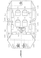
FIG. 1 is a diagram illustrating an example of an in-vehicle system in a vehicle according to the first embodiment. FIG. 2 is a plan view of the vehicle illustrating an example of an arrangement of each element of the in-vehicle system in the vehicle according to the first embodiment. The in-
車載システム1において、エアバッグECU10、衝突検知センサ21a−1〜21c−2、エアバッグ22a−1〜22c−2、車車間通信部23、監視センサ24、車両走行制御ECU25を有する。車載システム1において、エアバッグECU10は、衝突検知センサ21a−1〜21c−2、エアバッグ22a−1〜22c−2、車車間通信部23、監視センサ24、車両走行制御ECU25と接続される。
The in-
図2に示すように、(右前方)衝突検知センサ21a−1は、車両2の前方方向に向かって右前方に位置する。(左前方)衝突検知センサ21a−2は、車両2の前方方向に向かって左前方に位置する。(右側方前側)衝突検知センサ21b−1は、例えば2つのセンサを含み、車両2の前方方向に向かって右側方の前側に位置する。(左側方前側)衝突検知センサ21b−2は、例えば2つのセンサを含み、車両2の前方方向に向かって左側方の前側に位置する。(右側方後側)衝突検知センサ21c−1は、例えば2つのセンサを含み、車両2の前方方向に向かって右側方の後側に位置する。(左側方後側)衝突検知センサ21c−2は、例えば2つのセンサを含み、車両2の前方方向に向かって左側方の後側に位置する。
As shown in FIG. 2, the (right front) collision detection sensor 21 a-1 is located on the right front side in the forward direction of the
また、図2に示すように、(右前方)エアバッグ22a−1は、車両2の前方方向に向かって車両2の車室内の右前方に位置して車両2のエリア1と対応し、シート11sに着座する車両2の乗員を保護する。エリア1は、対象物と衝突しうる車両2の車体の右前方部分である。同様に、(左前方)エアバッグ22a−2は、車両2の前方方向に向かって車両2の車室内の左前方に位置して車両2のエリア2と対応し、シート12sに着座する車両2の乗員を保護する。エリア2は、対象物と衝突しうる車両2の車体の左前方部分である。
Further, as shown in FIG. 2, the (right front)
同様に、(右側方前側)エアバッグ22b−1は、車両2の前方方向に向かって車両2の車室内の右側方の前側に位置して車両2のエリア3と対応し、シート11sに着座する車両2の乗員を保護する。エリア3は、対象物と衝突しうる車両2の車体の右側方前側部分である。同様に、(左側方前側)エアバッグ22b−2は、車両2の前方方向に向かって車両2の車室内の左側方の前側に位置して車両2のエリア4と対応し、シート12sに着座する車両2の乗員を保護する。エリア4は、対象物と衝突しうる車両2の車体の左側方前側部分である。
Similarly, the (right front side)
同様に、(右側方後側)エアバッグ22c−1は、車両2の前方方向に向かって車両2の車室内の左側方の後側に位置して車両2のエリア5と対応し、シート21sに着座する車両2の乗員を保護する。エリア5は、対象物と衝突しうる車両2の車体の右側方後側部分である。同様に、(左側方後側)エアバッグ22c−2は、車両2の前方方向に向かって車両2の車室内の右側方の後側に位置して車両2のエリア6と対応し、シート22sに着座する車両2の乗員を保護する。エリア6は、対象物と衝突しうる車両2の車体の左側方後側部分である。
Similarly, the (right rear side)
また、図2に示すように、(右前方)衝突検知センサ21a−1は、(右前方)エアバッグ22a−1及び車両2のエリア1と対応し、車両2と対象物とのエリア1での衝突の際に検知した衝撃の加速度をエアバッグECU10へ出力する。この加速度と閾値との比較に基づいて、(右前方)エアバッグ22a−1が展開されるか否かが判定される。同様に、(左前方)衝突検知センサ21a−2は、(左前方)エアバッグ22a−2及び車両2のエリア2と対応し、車両2と対象物とのエリア2での衝突の際に検知した衝撃の加速度をエアバッグECU10へ出力する。この加速度と閾値との比較に基づいて、(左前方)エアバッグ22a−2が展開されるか否かが判定される。
Further, as shown in FIG. 2, the (right front)
同様に、(右側方前側)衝突検知センサ21b−1は、(右側方前側)エアバッグ22b−1及び車両2のエリア3と対応し、車両2と対象物とのエリア3での衝突の際に検知した衝撃の加速度をエアバッグECU10へ出力する。この加速度と閾値との比較に基づいて、(右側方前側)エアバッグ22b−1が展開されるか否かが判定される。同様に、(左側方前側)衝突検知センサ21b−2は、(左側方前側)エアバッグ22b−2及び車両2のエリア4と対応し、車両2と対象物とのエリア4での衝突の際に検知した衝撃の加速度をエアバッグECU10へ出力する。この加速度と閾値との比較に基づいて、(左側方前側)エアバッグ22b−2が展開されるか否かが判定される。
Similarly, the (right front side)
同様に、(右側方後側)衝突検知センサ21c−1は、(右側方後側)エアバッグ22c−1及び車両2のエリア5と対応し、車両2と対象物とのエリア5での衝突の際に検知した衝撃の加速度をエアバッグECU10へ出力する。この加速度と閾値との比較に基づいて、(右側方後側)エアバッグ22c−1が展開されるか否かが判定される。同様に、(左側方後側)衝突検知センサ21c−2は、(左側方後側)エアバッグ22c−2及び車両2のエリア6と対応し、車両2と対象物とのエリア6での衝突の際に検知した衝撃の加速度をエアバッグECU10へ出力する。この加速度と閾値との比較に基づいて、(左側方後側)エアバッグ22c−2が展開されるか否かが判定される。
Similarly, the (right rear side)
なお、車両2と衝突する対象物とは、他の車両、歩行者、物体等であり、動体及び静止物のいずれも含む。また、衝突検知センサ21a−1〜21c−2が衝撃の圧力を検知し、衝撃の圧力に応じて、対応するエアバッグが展開されるか否かが判定されるとしてもよい。あるいは、衝突検知センサ21a−1〜21c−2が衝撃を検知し、衝撃を示す指標に応じて、対応するエアバッグが展開されるか否かが判定されるとしてもよい。
In addition, the target object which collides with the
車車間通信部23は、例えばDCM(Data Communication Module)であり、車車間通信装置を搭載した他の車両との車車間通信を行う。実施形態1に関連する車車間通信では、自車が自動運転機能を搭載し、かつ自動運転機能が動作中であるか否かを他車へ送信し、また、他車が自動運転機能を搭載し、かつ自動運転機能が動作中であるか否かを他車から受信する。
The
監視センサ24は、例えばミリ波レーダーであり、A=自車を基準にした対象物の相対距離[m]及びB=自車を基準にした対象物の相対速度[m/s]を検知し、衝突予想時間TTC(Time To Collision)[s]=A/BをエアバッグECU10へ出力する。図2に示すように、監視センサ24は、前方及び側方前側監視センサならびに後方及び側方後側監視センサを含む。前方及び側方前側監視センサは、車両2の前方に取り付けられ、前方及び側方前側に位置する他の車両を相手車両とする。後方及び側方後側監視センサは、車両2の後方に取り付けられ、車両2の後方及び側方後側に位置する他の車両を相手車両とする。監視センサ24は、相手車両に関する衝突予想時間TTCをエアバッグECU10へ出力する。
The
なお、監視センサ24は、ミリ波レーダーに限らず、カメラ等の撮像装置であってもよい。また、監視センサ24の車両2への取付位置及び取付数は、車両2の全周囲を監視し、対象物が車両2と衝突する又は衝突する可能性がある衝突位置を特定できれば、図2に示す形態に限らず、いずれの取付位置及び取付数であってもよい。
The
車両走行制御ECU25は、車両2において自動運転機能が有効とされているときに、図示しないアクセル、ブレーキ、ステアリング、ギアシフト等を自動的に制御し、車両2の走行を自動制御する。
When the automatic driving function is enabled in the
また、車両走行制御ECU25は、車両2において自動運転機能が有効とされているときに、エアバッグECU10から、例えばステアリング制御及びブレーキ制御による衝突回避指示を受信する。そして、車両走行制御ECU25は、衝突回避指示を受信すると、ステアリング及びブレーキを自動制御して車両2と対象物との衝突の回避を試みる。また、車両走行制御ECU25は、車両2において自動運転機能が有効とされているときに、エアバッグECU10から、例えばブレーキ制御による衝突回避指示を受信すると、ブレーキを自動制御して車両2と対象物との衝突の回避を試みる。
Further, the vehicle
なお、車両走行制御ECU25は、車両2において自動運転機能が無効であっても、例えばステアリング制御、ブレーキ制御による衝突回避指示を受信すると、ステアリング、ブレーキを自動制御して車両2と対象物との衝突の回避を試みるとしてもよい。
Even if the automatic driving function is disabled in the
(実施形態1に係るエアバッグECU)
エアバッグECU10は、記憶装置及び処理装置が協働して処理を行う、例えばマイクロコンピュータである。エアバッグECU10は、衝突可能性判定部11、相手車両自動運転機能判定部12、衝突回避制御指示部13、衝突回避可能性判定部14、閾値変更制御部15、エアバッグ展開制御部16を有する。また、エアバッグECU10は、センサ及びエアバッグ対応関係記憶部17、エアバッグ展開閾値記憶部18を有する。以下、エアバッグECU10の各部の動作の説明は、車両2において自動運転機能が有効に動作していることを前提とする。しかし、エアバッグECU10の各部は、車両2において自動運転機能が動作していないときであっても、同様に動作してもよい。
(Airbag ECU according to Embodiment 1)
The
なお、センサ及びエアバッグ対応関係記憶部17は、図3に例示するセンサ及びエアバッグ対応関係テーブル17aを有する。センサ及びエアバッグ対応関係テーブル17aは、衝突検知センサ21a−1〜21c−2の各センサと、エアバッグ22a−1〜22c−2と、図2に示すエリア1〜エリア6の衝突位置との対応関係を示す。
The sensor and airbag
図3の例示では、(右前方)衝突検知センサ21a−1と、(右前方)エアバッグ22a−1と、エリア1とが対応することを示す。すなわち、(右前方)衝突検知センサ21a−1が検知する加速度に応じて(右前方)エアバッグ22a−1の展開が制御される。そして、推定される衝突位置がエリア1の場合、衝突検知センサ21a−1〜21c−2が検知する加速度を閾値判定する際の閾値を個別に変更する場合には、(右前方)衝突検知センサ21a−1の閾値を変更することを示す。その他の衝突検知センサ、エアバッグ、衝突位置についても同様である。
In the illustration of FIG. 3, the (right front) collision detection sensor 21 a-1, (right front) airbag 22 a-1 and the
また、エアバッグ展開閾値記憶部18は、図4に例示するエアバッグ展開閾値テーブル18aを有する。エアバッグ展開閾値テーブル18aは、衝突検知センサ21a−1〜21c−2の各センサと、各閾値との対応関係を示す。図4に示す例では、(右前方)衝突検知センサ21a−1が検知する加速度を閾値判定する場合のそれぞれの閾値1及び閾値2(閾値2<閾値1)を示す。閾値1は、デフォルト値である。
Further, the airbag deployment threshold
図4の例示では、(右前方)衝突検知センサ21a−1が検知する加速度を閾値判定する際の閾値1はTh11であり、閾値2はTh21である。その他の衝突検知センサならびに閾値1及び閾値2についても同様である。なお、各閾値1(Th11〜Th16)、各閾値2(Th21〜Th26)は、各衝突検知センサの設置位置等に応じて異なる値であってもよいし、同一の値であってもよい。
In the illustration of FIG. 4, the
衝突可能性判定部11は、例えばミリ波レーダーである監視センサ24から衝突危険性情報(TTC等)を受信し、衝突危険性情報をもとに、対象物との衝突の危険性を判定する。衝突可能性判定部11は、受信したTTCが所定値(T1)以下であるか否かを判定し、TTCが所定値以下である場合に、対象物との衝突の危険性があると判定する。なお、対象物との衝突の危険性がある場合とは、対象物が自車へ接近する場合を含む。
The collision
そして、衝突可能性判定部11は、対象物との衝突の危険性があると判定した場合には、車車間通信部23を制御して、対象物との車車間通信を開始させる。衝突可能性判定部11は、受信したTTCが所定値より大である場合に、対象物との衝突の危険性がないと判定し、車車間通信部23に車車間通信を開始させない。
When the collision
なお、車車間通信部23は、対象物が車車間通信に対応していない車両である場合、もしくは、対象物が車両以外の人や物体である場合には、対象物との車車間通信のネゴシエーションが成立しないので、車車間通信を行わない。
The
相手車両自動運転機能判定部12は、対象物との衝突の危険性があると判定された対象物である相手車両との車車間通信により、相手車両に、相手車両が自動運転機能を搭載しているか否かを問い合わせる。また、相手車両自動運転機能判定部12は、車車間通信により、相手車両が自動運転機能を搭載している場合に自動運転機能が動作中であるか否かを問合わせる。
The partner vehicle automatic driving
そして、相手車両自動運転機能判定部12は、相手車両から、問合わせに対する応答を所定時間経過後も受信しない、又は、相手車両が自動運転機能を搭載していない旨の応答を受信する、又は、相手車両が自動運転機能を搭載するが動作中でなく無効である旨の応答を受信する。すると、相手車両自動運転機能判定部12は、受信に応じて、自動運転未対応制御に切り替える。
And the partner vehicle automatic driving
他方、相手車両自動運転機能判定部12は、相手車両から、所定時間内に、相手車両が自動運転機能を搭載しており自動運転機能が動作中であり有効である旨の応答を受信すると、自動運転対応制御に切り替える。“問合わせに対する応答を所定時間経過しても受信しない”とは、対象物が人や物体である場合、もしくは、対象物が車両であっても自動運転機能を搭載していない場合である。
On the other hand, when the partner vehicle automatic driving
衝突回避制御指示部13は、相手車両自動運転機能判定部12により自動運転未対応制御に切り替えられると、車両走行制御ECU25に対して、図示しない車両2のブレーキのみを制御して対象物との衝突回避を行う第2衝突回避制御モード信号を送信する。車両走行制御ECU25は、衝突回避制御指示部13から第2衝突回避制御モード信号を受信すると、ブレーキのみを制御して対象物との衝突回避を行う。なお、自動運転未対応制御の場合に、ブレーキのみを制御して対象物との衝突回避を行うのは、対象物の動きが予測できないためである。
When the counterpart vehicle automatic driving
他方、衝突回避制御指示部13は、相手車両自動運転機能判定部12により自動運転対応制御に切り替えられると、車両走行制御ECU25に対して、図示しない車両2のステアリング及びブレーキを制御して対象物との衝突回避を行う第1衝突回避制御モード信号を送信する。車両走行制御ECU25は、衝突回避制御指示部13から第1衝突回避制御モード信号を受信すると、ステアリング及びブレーキを制御して対象物との衝突回避を行う。
On the other hand, the collision avoidance
なお、第1衝突回避制御モード及び第2衝突回避制御モードは、第1衝突回避制御モードよりも第2衝突回避制御モードが車両2の自動走行制御の度合いが低いという関係が成立すれば、どのような形態の衝突回避制御モードであってもよい。実施形態1では、第1衝突回避制御モードではステアリング及びブレーキを制御して対象物との衝突回避を行い、第2衝突回避制御モードではブレーキのみを制御して対象物との衝突回避を行う。しかし、これに限定されず、例えば第1衝突回避制御モードではステアリング、ブレーキ、及びギアシフトを制御して対象物との衝突回避を行い、第2衝突回避制御モードではブレーキのみを制御して対象物との衝突回避を行うとしてもよい。
The first collision avoidance control mode and the second collision avoidance control mode may be any if the second collision avoidance control mode has a lower degree of automatic travel control of the
衝突回避可能性判定部14は、衝突回避制御指示部13によりいずれかの衝突回避制御モード信号が送信された後、例えばミリ波レーダーである監視センサ24から衝突危険性情報(TTC等)を受信する。そして、衝突回避可能性判定部14は、衝突危険性情報をもとに、対象物との衝突が回避可能かを判定する。衝突回避可能性判定部14は、受信したTTCが所定値(T2(<T1))以下であるか否かを判定し、TTCが所定値以下である場合に、対象物との衝突が回避不可能であると判定する。
The collision avoidance
閾値変更制御部15は、衝突回避制御指示部13により自動運転未対応制御に切り替えられ、衝突回避可能性判定部14により対象物との衝突が回避不可能であると判定されると、衝突検知センサ21a−1〜21c−2が検知する加速度を閾値判定する際の各閾値を閾値2へ変更する。エアバッグ展開制御部16は、衝突検知センサ21a−1〜21c−2の閾値をエアバッグ展開閾値テーブル18aから読み出す際に、全ての衝突検知センサについて各閾値2を読み出す。
The threshold value
エアバッグ展開制御部16は、衝突検知センサ21a−1〜21c−2の各閾値が閾値2へ切り替えられることにより、エアバッグ22a−1〜22c−2を衝突に敏感に反応して展開し、想定できない衝突形態にも対応して乗員を適切に保護することができる。
The airbag
なお、閾値変更制御部15は、衝突回避制御指示部13により自動運転未対応制御に切り替えられたが、衝突回避可能性判定部14により対象物との衝突が回避可能であると判定されると、閾値の変更は行わない。
The threshold value
また、閾値変更制御部15は、衝突回避制御指示部13により自動運転対応制御に切り替えられ、衝突回避可能性判定部14により対象物との衝突が回避不可能であると判定されると、監視センサ24から受信する衝突予測位置情報をもとにセンサ及びエアバッグ対応関係テーブル17aを参照する。そして、閾値変更制御部15は、衝突位置と対応する衝突検知センサ21a−1〜21c−2を判定する。そして、閾値変更制御部15は、衝突位置と対応すると判定した衝突検知センサの閾値を閾値2へ変更する。
Further, the threshold value
例えば、監視センサ24から受信する衝突予測位置情報がエリア1を示す場合には、センサ及びエアバッグ対応関係テーブル17aから、エリア1に対応する衝突検知センサは、(右前方)衝突検知センサ21a−1である。(右前方)衝突検知センサ21a−1が、エリア1に最も近い衝突検知センサの一例である。
For example, when the predicted collision position information received from the
よって、閾値変更制御部15は、監視センサ24から受信する衝突予測位置情報がエリア1を示す場合には、(右前方)衝突検知センサ21a−1のみの閾値を閾値2へ変更する。その他のエリア及び衝突検知センサについても同様である。
Accordingly, the threshold value
エアバッグ展開制御部16は、全ての衝突検知センサ21a−1〜21c−2の閾値をエアバッグ展開閾値テーブル18aから読み出す際に、閾値2へ閾値が変更された衝突検知センサについては閾値2を読み出し、閾値が変更されず閾値1のままである衝突検知センサについては閾値1を読み出す。
When the airbag
エアバッグ展開制御部16は、衝突位置に最も近い衝突検知センサの閾値が閾値2へ切り替えられることにより、衝突位置に最も近いエアバッグ以外のエアバッグの過剰な展開を抑制することができる。
The airbag
なお、閾値変更制御部15は、衝突回避制御指示部13により自動運転対応制御に切り替えられたが、衝突回避可能性判定部14により対象物との衝突が回避可能であると判定されると、閾値の変更は行わない。
The threshold value
(実施形態1に係るエアバッグ展開閾値制御処理)
図5は、実施形態1に係るエアバッグ展開閾値制御処理の一例を示すフローチャートである。実施形態1に係るエアバッグ展開閾値制御処理は、エアバッグECU10により、所定の周期又は所定の契機で実行される。
(Airbag deployment threshold value control process according to Embodiment 1)
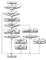
FIG. 5 is a flowchart illustrating an example of an airbag deployment threshold value control process according to the first embodiment. The airbag deployment threshold control process according to the first embodiment is executed by the
先ず、衝突可能性判定部11は、監視センサ24から衝突危険情報(例えばTTC)を受信したか否かを判定する(ステップS11)。衝突可能性判定部11は、衝突危険情報を受信した場合(ステップS11:Yes)、ステップS12へ処理を移し、衝突危険情報を受信していない場合(ステップS11:No)、ステップS11を繰り返す。
First, the collision
ステップS12では、衝突可能性判定部11は、ステップS11で受信した衝突危険情報が所定値以下(例えばTTC≦T1)、つまり衝突の可能性があるか否かを判定する。衝突可能性判定部11は、受信した衝突危険情報が所定値以下である場合(ステップS12:Yes)、ステップS13へ処理を移す。一方、衝突可能性判定部11は、受信した衝突危険情報が所定値より大である場合(ステップS12:No)、実施形態1に係るエアバッグ展開閾値制御処理を終了する。
In step S12, the collision
ステップS13では、衝突可能性判定部11は、衝突危険情報が所定値以下であるため、対象物との衝突の危険性があると判定して車車間通信部23を制御し、対象物である相手車両との車車間通信を開始させる。
In step S13, the collision
次に、相手車両自動運転機能判定部12は、車車間通信により、相手車両に、相手車両が自動運転機能を搭載しているか否か、相手車両が自動運転機能を搭載している場合に自動運転機能が動作中であるか否かを問合わせる。そして、相手車両自動運転機能判定部12は、車車間通信により、相手車両から所定時間内に受信した応答が、相手車両が自動運転機能を搭載しており自動運転機能が動作中であり有効である旨の応答であるか否かを判定する(以上、ステップS14)。
Next, the partner vehicle automatic driving
相手車両自動運転機能判定部12は、相手車両が自動運転機能を搭載しており自動運転機能が動作中であり有効である旨の応答を受信した場合(ステップS14:Yes)、自動運転対応制御に切り替え、ステップS15へ処理を移す。一方、相手車両自動運転機能判定部12は、相手車両が自動運転機能を搭載しており自動運転機能が動作中であり有効である旨の応答を受信した以外の場合(ステップS14:No)、自動運転未対応制御に切り替え、ステップS19へ処理を移す。
The partner vehicle automatic driving
ステップS15では、衝突回避制御指示部13は、相手車両自動運転機能判定部12により自動運転対応制御に切り替えられると、車両走行制御ECU25に対して、車両2のステアリング及びブレーキを制御して対象物との衝突回避を行う第1衝突回避制御モード信号を送信する。次に、衝突回避可能性判定部14は、衝突回避制御指示部13から第1衝突回避制御モード信号を受信した後、例えばミリ波レーダーである監視センサ24から衝突危険性情報(TTC等)を受信する。そして、衝突回避可能性判定部14は、受信したTTCが所定値(T2(<T1))以下であるか否かに基づき、対象物との衝突が回避可能かを判定する(ステップS16)。
In step S15, the collision avoidance
衝突回避可能性判定部14は、対象物との衝突が回避可能である場合(ステップS16:Yes)、実施形態1に係るエアバッグ展開閾値制御処理を終了し、対象物との衝突が回避可能でない場合(ステップS16:No)、ステップS17へ処理を移す。
When the collision
ステップS17では、閾値変更制御部15は、ステップS14で自動運転対応制御に切り替えられ、ステップS16で対象物との衝突が回避不可能であると判定されると、監視センサ24から受信する衝突予測位置情報をもとにセンサ及びエアバッグ対応関係テーブル17aを参照する。そして、閾値変更制御部15は、衝突位置に最も近い衝突検知センサ21a−1〜21c−2を判定する。
In step S17, the threshold value
次に、閾値変更制御部15は、ステップS17で最も近いと判定された衝突検知センサ21a−1〜21c−2の閾値を閾値2へ変更する(ステップS18)。ステップS18が終了すると、エアバッグECU10は、実施形態1に係るエアバッグ展開閾値制御処理を終了する。
Next, the threshold value
他方、ステップS19では、衝突回避制御指示部13は、相手車両自動運転機能判定部12により自動運転未対応制御に切り替えられると、車両走行制御ECU25に対して、車両2のブレーキのみを制御して対象物との衝突回避を行う第2衝突回避制御モード信号を送信する。次に、衝突回避可能性判定部14は、衝突回避制御指示部13から第2衝突回避制御モード信号を受信後、例えばミリ波レーダーである監視センサ24から衝突危険性情報(TTC等)を受信する。そして、衝突回避可能性判定部14は、受信したTTCが所定値(T2(<T1))以下であるか否かに基づき、対象物との衝突が回避可能かを判定する(ステップS20)。
On the other hand, in step S19, the collision avoidance
衝突回避可能性判定部14は、対象物との衝突が回避可能である場合(ステップS20:Yes)、実施形態1に係るエアバッグ展開閾値制御処理を終了し、対象物との衝突が回避可能でない場合(ステップS20:No)、ステップS21へ処理を移す。
When the collision
ステップS21では、閾値変更制御部15は、ステップS14で自動運転未対応制御に切り替えられ、ステップS20で対象物との衝突が回避不可能であると判定されると、全ての衝突検知センサ21a−1〜21c−2の閾値を閾値2へ変更する。ステップS21が終了すると、エアバッグECU10は、実施形態1に係るエアバッグ展開閾値制御処理を終了する。
In step S21, the threshold value changing
(実施形態1に係るエアバッグ展開制御処理)
図6は、実施形態1に係るエアバッグ展開制御処理の一例を示すフローチャートである。実施形態1に係るエアバッグ展開制御処理は、エアバッグECU10により、所定の周期又は所定の契機で実行される。
(Airbag deployment control process according to Embodiment 1)
FIG. 6 is a flowchart illustrating an example of the airbag deployment control process according to the first embodiment. The airbag deployment control process according to the first embodiment is executed by the
先ず、エアバッグ展開制御部16は、検知加速度がそれぞれの閾値以上となった衝突検知センサがあるか否かを判定する(ステップS31)。エアバッグ展開制御部16は、検知加速度がそれぞれの閾値以上となった衝突検知センサがある場合(ステップS31:Yes)、検知加速度がそれぞれの閾値以上となった衝突検知センサと対応する全てのエアバッグを展開する(ステップS32)。エアバッグ展開制御部16は、ステップS32が終了すると、実施形態1に係るエアバッグ展開制御処理を終了する。他方、エアバッグ展開制御部16は、検知加速度がそれぞれの閾値以上となった衝突検知センサがない場合(ステップS31:No)、ステップS31を繰り返す。
First, the airbag
以上の実施形態1によれば、エアバッグECU10が、相手車両の自動運転機能が有効であるか否かに応じて衝突検知センサ21a−1〜21c−2の判定閾値を変更する又は判定閾値の変更方法を切り替える。よって、相手車両の予測される動きに基づいて適切にエアバッグを作動させることができる。
According to the first embodiment described above, the
また、相手車両の自動運転機能が有効である場合に、衝突予測位置情報をもとにエアバッグ展開のための最小限の衝突検知センサの閾値を変更することで、エアバッグの過剰な展開を抑制できる。 In addition, when the automatic driving function of the partner vehicle is effective, the airbag can be excessively deployed by changing the minimum threshold of the collision detection sensor for airbag deployment based on the predicted collision position information. Can be suppressed.
[実施形態2]
実施形態1では、衝突検知センサが検知する加速度もしくは圧力と比較する、エアバッグを展開するか否かの閾値の変更又は切り替えを、エアバッグECUが行う。しかし、これに限らず、閾値の変更又は切り替えを、エアバッグECUよりも上位のECUが行ってもよい。実施形態2では、閾値の変更又は切り替えを、エアバッグECUよりも上位のECUが行う例について説明する。
[Embodiment 2]
In the first embodiment, the airbag ECU changes or switches the threshold value of whether or not to deploy the airbag, which is compared with the acceleration or pressure detected by the collision detection sensor. However, the present invention is not limited thereto, and the threshold value may be changed or switched by an ECU higher than the airbag ECU. In the second embodiment, an example will be described in which a threshold ECU is changed or switched by an ECU higher than the airbag ECU.
図7は、実施形態2に係る車両における車載システムの一例を示す図である。実施形態2に係る車載システム1Aは、車両2Aに搭載される各種のECUやセンサ類を含む各種機器を有するシステムである。
FIG. 7 is a diagram illustrating an example of an in-vehicle system in a vehicle according to the second embodiment. The in-
車載システム1Aにおいて、エアバッグECU10A、衝突検知センサ21a−1〜21c−2、エアバッグ22a−1〜22c−2、車車間通信部23、監視センサ24、車両走行制御ECU25、上位ECU30を有する。車載システム1Aにおいて、上位ECU30は、エアバッグECU10A、車車間通信部23、監視センサ24、車両走行制御ECU25と接続される。また、車載システム1Aにおいて、エアバッグECU10Aは、衝突検知センサ21a−1〜21c−2、エアバッグ22a−1〜22c−2、上位ECU30と接続される。
The in-
上位ECU30は、衝突可能性判定部11、相手車両自動運転機能判定部12、衝突回避制御指示部13、衝突回避可能性判定部14、閾値変更制御部15、センサ及びエアバッグ対応関係記憶部17を有する。また、エアバッグECU10Aは、エアバッグ展開制御部16、エアバッグ展開閾値記憶部18を有する。これら各部は、実施形態1の同一符号の各部と同様である。
The
すなわち、実施形態2では、監視センサ24により取得される衝突危険性情報、車車間通信部23を介して相手車両から受信される相手車両の自動運転機能が有効又は無効の情報、車両走行制御ECU25により衝突回避制御した場合に監視センサ24により取得される衝突回避可能性に応じて、衝突検知センサ21a−1〜21c−2の展開の閾値を切り替える処理を、上位ECU30が行う。
That is, in the second embodiment, the collision risk information acquired by the
[実施形態1〜2の変形例]
実施形態1〜2では、エアバッグを展開するか否かを判定する、衝突検知センサが検知する加速度もしくは圧力の閾値を変更する。しかし、開示の技術は、エアバッグに限定されるものではなく、シートベルト等の乗員保護装置に広く適用可能である。
[Modification of
In the first and second embodiments, the threshold value of the acceleration or pressure detected by the collision detection sensor that determines whether or not to deploy the airbag is changed. However, the disclosed technology is not limited to an airbag, and can be widely applied to an occupant protection device such as a seat belt.
例えば、シートベルトは、衝突検知センサが検知する加速度もしくは圧力を閾値判定し、加速度もしくは圧力が閾値を超えた場合にベルトをロックして乗員が座席から投げ出されないようにする。そして、監視センサ24により取得される衝突危険性情報、車車間通信部23を介して相手車両から受信される相手車両の自動運転機能が有効又は無効の情報、車両走行制御ECU25により衝突回避制御した場合に監視センサ24により取得される衝突回避可能性に応じて、シートベルトをロックする閾値を変更する。
For example, the seat belt determines the threshold value of the acceleration or pressure detected by the collision detection sensor, and locks the belt to prevent the occupant from being thrown out of the seat when the acceleration or pressure exceeds the threshold value. Then, collision risk information acquired by the
これにより、シートベルトの過剰なロックを抑制し、最小限のロックにより乗員を適切に保護することができる。このように、衝突検知センサが検知する加速度もしくは圧力を閾値判定した結果に応じて作動する乗員保護装置であれば、開示の技術は適用可能である。 As a result, excessive locking of the seat belt can be suppressed, and the occupant can be appropriately protected with the minimum lock. As described above, the disclosed technique can be applied to any occupant protection device that operates according to a result of threshold determination of acceleration or pressure detected by the collision detection sensor.
実施形態1〜2において説明した各処理のうち、自動的に行われるものとして説明した処理の全部又は一部を手動的に行うこともできる。もしくは、実施形態1〜2において説明した各処理のうち、手動的に行われるものとして説明した処理の全部又は一部を公知の方法で自動的に行うこともできる。 Of the processes described in the first and second embodiments, all or part of the processes described as being automatically performed can be manually performed. Alternatively, all or part of the processes described as being manually performed among the processes described in the first and second embodiments can be automatically performed by a known method.
また、実施形態1〜2において説明した各部の統合及び分散は、処理負荷や処理効率をもとに適宜変更することができる。この他、上述及び図示の処理手順、制御手順、具体的名称、各種のデータやパラメータを含む情報については、特記する場合を除いて適宜変更することができる。 Further, the integration and distribution of the units described in the first and second embodiments can be changed as appropriate based on the processing load and the processing efficiency. In addition, the above-described and illustrated processing procedures, control procedures, specific names, and information including various data and parameters can be changed as appropriate unless otherwise specified.
さらなる効果や変形例は、当業者によって容易に導き出すことができる。このため、開示の技術のより広範な態様は、上記のように表しかつ記述した特定の詳細及び代表的な実施形態に限定されるものではない。したがって、添付の特許請求の範囲及びその均等物によって定義される総括的な発明の概念の精神または範囲から逸脱することなく、様々な変更が可能である。 Further effects and modifications can be easily derived by those skilled in the art. Thus, the broader aspects of the disclosed technology are not limited to the specific details and representative embodiments illustrated and described above. Accordingly, various modifications can be made without departing from the spirit or scope of the general inventive concept as defined by the appended claims and their equivalents.
1、1A 車載システム
2、2A 車両
10、10A エアバッグECU
11s、12s、21s、22s シート
11 衝突可能性判定部
12 相手車両自動運転機能判定部
13 衝突回避制御指示部
14 衝突回避可能性判定部
15 閾値変更制御部
16 エアバッグ展開制御部
17 センサ及びエアバッグ対応関係記憶部
17a センサ及びエアバッグ対応関係テーブル
18 エアバッグ展開閾値記憶部
18a エアバッグ展開閾値テーブル
21a−1 (右前方)衝突検知センサ
21a−2 (左前方)衝突検知センサ
21b−1 (右側方前側)衝突検知センサ
21b−2 (左側方前側)衝突検知センサ
21c−1 (右側方後側)衝突検知センサ
21c−2 (左側方後側)衝突検知センサ
22a−1 (右前方)エアバッグ
22a−2 (左前方)エアバッグ
22b−1 (右側方前側)エアバッグ
22b−2 (左側方前側)エアバッグ
22c−1 (右側方後側)エアバッグ
22c−2 (左側方後側)エアバッグ
23 車車間通信部
24 監視センサ
25 車両走行制御ECU
30 上位ECU
1, 1A In-
11s, 12s, 21s,
30 host ECU
Claims (5)
自車へ接近する他車を検知する車両検知部により検知された他車における自動運転機能の動作の有無を判定する自動運転機能判定部と、
前記自動運転機能判定部による判定結果に応じて前記閾値を変更する閾値変更部と
を備えることを特徴とする乗員保護装置。 An index indicating an impact detected by a collision detection unit that detects an impact at the time of a collision between the host vehicle and another vehicle is compared with a threshold, and when the index is equal to or greater than the threshold, the impact of a collision with another vehicle A protection activation control unit that activates an occupant protection unit that protects the occupant of the vehicle from
An automatic driving function determination unit that determines the presence or absence of the operation of the automatic driving function in the other vehicle detected by the vehicle detection unit that detects another vehicle approaching the host vehicle;
An occupant protection device comprising: a threshold value changing unit that changes the threshold value according to a determination result by the automatic driving function determining unit.
ことを特徴とする請求項1に記載の乗員保護装置。 The occupant protection device according to claim 1, wherein the vehicle detection unit detects another vehicle approaching the host vehicle when an automatic driving function is operating in the host vehicle.
前記閾値変更部は、前記自動運転機能判定部により、他車において自動運転機能の動作ありと判定された場合には、該他車との衝突予測位置の所定近傍に位置する前記衝突検知部により検知された衝撃を示す指標と比較する前記閾値をより小さい値へ変更し、他車において自動運転機能の動作なしと判定された場合には、前記衝突検知部が前記所定近傍に位置するか否かに関わらず前記閾値をより小さい値へ変更する
ことを特徴とする請求項1又は2に記載の乗員保護装置。 The plurality of occupant protection units and the plurality of collision detection units respectively correspond,
When the automatic driving function determining unit determines that there is an automatic driving function in another vehicle, the threshold value changing unit is configured to be detected by the collision detecting unit located in a predetermined vicinity of the predicted collision position with the other vehicle. When the threshold value to be compared with the index indicating the detected impact is changed to a smaller value, and it is determined that the automatic driving function is not operating in another vehicle, whether or not the collision detection unit is positioned in the predetermined vicinity. The occupant protection device according to claim 1, wherein the threshold value is changed to a smaller value regardless of whether the threshold value is lower.
前記車両走行制御装置による前記第1の衝突回避制御又は前記第2の衝突回避制御の後に、他車との衝突が回避可能であるか否かを判定する衝突回避可能性判定部と
をさらに備え、
前記閾値変更部は、前記衝突回避可能性判定部により他車との衝突が回避不可能であると判定された場合に前記閾値を変更する
ことを特徴とする請求項1、2又は3に記載の乗員保護装置。 When it is determined by the automatic driving function determination unit that the operation of the automatic driving function is performed in another vehicle, the vehicle traveling control device is instructed to perform first collision avoidance control for avoiding a collision with the other vehicle, When it is determined that the operation of the automatic driving function is not performed in another vehicle, the vehicle traveling control device is instructed to perform the second collision avoiding control having a degree of automatic traveling control lower than that of the first collision avoiding control. An avoidance control instruction unit;
A collision avoidance possibility determination unit for determining whether or not a collision with another vehicle can be avoided after the first collision avoidance control or the second collision avoidance control by the vehicle travel control device; ,
The threshold value changing unit changes the threshold value when it is determined by the collision avoidance possibility determining unit that a collision with another vehicle cannot be avoided. Occupant protection device.
自車と他車との衝突の際の衝撃を検知する衝突検知部により検知された衝撃を示す指標と比較し、該指標が前記閾値以上である場合に、他車との衝突の衝撃から自車の乗員を保護する乗員保護部を作動させる保護作動制御ステップと、
自車へ接近する他車を検知する車両検知部により検知された他車における自動運転機能の動作の有無を判定する自動運転機能判定ステップと、
前記自動運転機能判定ステップによる判定結果に応じて前記閾値を変更する閾値変更ステップと
を含んだことを特徴とする乗員保護方法。 An occupant protection method performed by an occupant protection device,
Compared with the index indicating the impact detected by the collision detection unit that detects the impact at the time of the collision between the host vehicle and the other vehicle. A protective operation control step for activating an occupant protection unit that protects a vehicle occupant;
An automatic driving function determination step for determining the presence or absence of the operation of the automatic driving function in the other vehicle detected by the vehicle detection unit that detects another vehicle approaching the host vehicle;
And a threshold value changing step for changing the threshold value in accordance with a determination result in the automatic driving function determination step.
Priority Applications (1)
| Application Number | Priority Date | Filing Date | Title |
|---|---|---|---|
| JP2016092599A JP2017200791A (en) | 2016-05-02 | 2016-05-02 | Occupant protection device and occupant protection method |
Applications Claiming Priority (1)
| Application Number | Priority Date | Filing Date | Title |
|---|---|---|---|
| JP2016092599A JP2017200791A (en) | 2016-05-02 | 2016-05-02 | Occupant protection device and occupant protection method |
Publications (1)
| Publication Number | Publication Date |
|---|---|
| JP2017200791A true JP2017200791A (en) | 2017-11-09 |
Family
ID=60264918
Family Applications (1)
| Application Number | Title | Priority Date | Filing Date |
|---|---|---|---|
| JP2016092599A Pending JP2017200791A (en) | 2016-05-02 | 2016-05-02 | Occupant protection device and occupant protection method |
Country Status (1)
| Country | Link |
|---|---|
| JP (1) | JP2017200791A (en) |
Cited By (6)
| Publication number | Priority date | Publication date | Assignee | Title |
|---|---|---|---|---|
| JP2018118615A (en) * | 2017-01-25 | 2018-08-02 | トヨタ自動車株式会社 | Occupant protection device for vehicle and occupant protection method for vehicle |
| JP2019137263A (en) * | 2018-02-13 | 2019-08-22 | スズキ株式会社 | Driving support device |
| JP2020030806A (en) * | 2018-06-26 | 2020-02-27 | トヨタ自動車株式会社 | Detection of drowsy driver on the basis of vehicle to everything (v2x) communication |
| KR20200133855A (en) * | 2019-05-20 | 2020-12-01 | 현대모비스 주식회사 | Autonomous driving apparatus and method |
| KR20200133854A (en) * | 2019-05-20 | 2020-12-01 | 현대모비스 주식회사 | Autonomous driving apparatus and method |
| JP2021024457A (en) * | 2019-08-06 | 2021-02-22 | 株式会社Subaru | Vehicular travel control system |
-
2016
- 2016-05-02 JP JP2016092599A patent/JP2017200791A/en active Pending
Cited By (17)
| Publication number | Priority date | Publication date | Assignee | Title |
|---|---|---|---|---|
| US11338751B2 (en) | 2017-01-25 | 2022-05-24 | Toyota Jidosha Kabushiki Kaisha | Occupant protection device for vehicle and occupant protection method for vehicle |
| JP2018118615A (en) * | 2017-01-25 | 2018-08-02 | トヨタ自動車株式会社 | Occupant protection device for vehicle and occupant protection method for vehicle |
| JP2019137263A (en) * | 2018-02-13 | 2019-08-22 | スズキ株式会社 | Driving support device |
| JP7119405B2 (en) | 2018-02-13 | 2022-08-17 | スズキ株式会社 | Driving support device for straddle-type vehicle |
| JP2020030806A (en) * | 2018-06-26 | 2020-02-27 | トヨタ自動車株式会社 | Detection of drowsy driver on the basis of vehicle to everything (v2x) communication |
| JP7318360B2 (en) | 2018-06-26 | 2023-08-01 | トヨタ自動車株式会社 | Drowsy Driver Detection Based on Vehicle-to-Thing Communication |
| KR102678197B1 (en) | 2019-05-20 | 2024-06-26 | 현대모비스 주식회사 | Autonomous driving apparatus and method |
| KR20200133854A (en) * | 2019-05-20 | 2020-12-01 | 현대모비스 주식회사 | Autonomous driving apparatus and method |
| KR102678198B1 (en) * | 2019-05-20 | 2024-06-26 | 현대모비스 주식회사 | Autonomous driving apparatus and method |
| KR20200133855A (en) * | 2019-05-20 | 2020-12-01 | 현대모비스 주식회사 | Autonomous driving apparatus and method |
| KR20240107064A (en) * | 2019-05-20 | 2024-07-08 | 현대모비스 주식회사 | Autonomous driving apparatus and method |
| KR20240107065A (en) * | 2019-05-20 | 2024-07-08 | 현대모비스 주식회사 | Autonomous driving apparatus and method |
| KR102691754B1 (en) * | 2019-05-20 | 2024-08-06 | 현대모비스 주식회사 | Autonomous driving apparatus and method |
| KR102691753B1 (en) | 2019-05-20 | 2024-08-06 | 현대모비스 주식회사 | Autonomous driving apparatus and method |
| JP2021024457A (en) * | 2019-08-06 | 2021-02-22 | 株式会社Subaru | Vehicular travel control system |
| US11661080B2 (en) | 2019-08-06 | 2023-05-30 | Subaru Corporation | Vehicle traveling control system |
| JP7312054B2 (en) | 2019-08-06 | 2023-07-20 | 株式会社Subaru | Vehicle cruise control system |
Similar Documents
| Publication | Publication Date | Title |
|---|---|---|
| JP2017200791A (en) | Occupant protection device and occupant protection method | |
| CN108156822B (en) | Vehicle control device and vehicle control method | |
| US10843687B2 (en) | Arrangement and method for mitigating a forward collision between road vehicles | |
| US7138938B1 (en) | System and method for preemptively sensing an object and selectively operating both a collision countermeasure system and a parking assistance system aboard an automotive vehicle | |
| JP6760221B2 (en) | Control device | |
| JP2011037308A (en) | Vehicular occupant protection system | |
| JP6032220B2 (en) | Vehicle control apparatus and vehicle control system | |
| JP6753324B2 (en) | Vehicle occupant protection device and vehicle occupant protection method | |
| CN108602494B (en) | Vehicle control device and vehicle control method | |
| US9415737B2 (en) | Vehicle occupant protection device | |
| US8855884B1 (en) | Occupant protection system | |
| EP2262667B1 (en) | Vision system for deploying safety systems | |
| KR20190123932A (en) | Rear-side alert system and controlling method thereof | |
| US9358977B2 (en) | Vehicle control apparatus | |
| JP2010018230A (en) | Occupant crash protection device and method for changing operating condition | |
| JP2017194926A (en) | Vehicle control apparatus and vehicle control method | |
| JP2016002898A (en) | Vehicular collision control apparatus | |
| US10112588B2 (en) | Vehicle control apparatus | |
| JP2015140146A (en) | Vehicle control device and vehicle control system | |
| JP2005537986A (en) | Apparatus and method for detecting an object or occupant in an interior of a vehicle | |
| CN115520131A (en) | Alighting assistance device, alighting assistance method, and non-transitory storage medium | |
| JP4171883B2 (en) | Collision prediction controller | |
| JP2008290496A (en) | Operation control device | |
| JP2007290489A (en) | Vehicular collision determining device | |
| WO2019193916A1 (en) | Method for controlling pedestrian protection device, and protection control apparatus |