JP7318360B2 - Drowsy Driver Detection Based on Vehicle-to-Thing Communication - Google Patents
Drowsy Driver Detection Based on Vehicle-to-Thing Communication Download PDFInfo
- Publication number
- JP7318360B2 JP7318360B2 JP2019118632A JP2019118632A JP7318360B2 JP 7318360 B2 JP7318360 B2 JP 7318360B2 JP 2019118632 A JP2019118632 A JP 2019118632A JP 2019118632 A JP2019118632 A JP 2019118632A JP 7318360 B2 JP7318360 B2 JP 7318360B2
- Authority
- JP
- Japan
- Prior art keywords
- vehicle
- driver
- message
- connected vehicle
- dsrc
- Prior art date
- Legal status (The legal status is an assumption and is not a legal conclusion. Google has not performed a legal analysis and makes no representation as to the accuracy of the status listed.)
- Active
Links
Images


Classifications
-
- G—PHYSICS
- G06—COMPUTING; CALCULATING OR COUNTING
- G06V—IMAGE OR VIDEO RECOGNITION OR UNDERSTANDING
- G06V20/00—Scenes; Scene-specific elements
- G06V20/50—Context or environment of the image
- G06V20/59—Context or environment of the image inside of a vehicle, e.g. relating to seat occupancy, driver state or inner lighting conditions
- G06V20/597—Recognising the driver's state or behaviour, e.g. attention or drowsiness
-
- G—PHYSICS
- G08—SIGNALLING
- G08B—SIGNALLING OR CALLING SYSTEMS; ORDER TELEGRAPHS; ALARM SYSTEMS
- G08B21/00—Alarms responsive to a single specified undesired or abnormal condition and not otherwise provided for
- G08B21/02—Alarms for ensuring the safety of persons
- G08B21/06—Alarms for ensuring the safety of persons indicating a condition of sleep, e.g. anti-dozing alarms
-
- B—PERFORMING OPERATIONS; TRANSPORTING
- B60—VEHICLES IN GENERAL
- B60W—CONJOINT CONTROL OF VEHICLE SUB-UNITS OF DIFFERENT TYPE OR DIFFERENT FUNCTION; CONTROL SYSTEMS SPECIALLY ADAPTED FOR HYBRID VEHICLES; ROAD VEHICLE DRIVE CONTROL SYSTEMS FOR PURPOSES NOT RELATED TO THE CONTROL OF A PARTICULAR SUB-UNIT
- B60W40/00—Estimation or calculation of non-directly measurable driving parameters for road vehicle drive control systems not related to the control of a particular sub unit, e.g. by using mathematical models
- B60W40/08—Estimation or calculation of non-directly measurable driving parameters for road vehicle drive control systems not related to the control of a particular sub unit, e.g. by using mathematical models related to drivers or passengers
-
- B—PERFORMING OPERATIONS; TRANSPORTING
- B60—VEHICLES IN GENERAL
- B60K—ARRANGEMENT OR MOUNTING OF PROPULSION UNITS OR OF TRANSMISSIONS IN VEHICLES; ARRANGEMENT OR MOUNTING OF PLURAL DIVERSE PRIME-MOVERS IN VEHICLES; AUXILIARY DRIVES FOR VEHICLES; INSTRUMENTATION OR DASHBOARDS FOR VEHICLES; ARRANGEMENTS IN CONNECTION WITH COOLING, AIR INTAKE, GAS EXHAUST OR FUEL SUPPLY OF PROPULSION UNITS IN VEHICLES
- B60K28/00—Safety devices for propulsion-unit control, specially adapted for, or arranged in, vehicles, e.g. preventing fuel supply or ignition in the event of potentially dangerous conditions
- B60K28/02—Safety devices for propulsion-unit control, specially adapted for, or arranged in, vehicles, e.g. preventing fuel supply or ignition in the event of potentially dangerous conditions responsive to conditions relating to the driver
- B60K28/06—Safety devices for propulsion-unit control, specially adapted for, or arranged in, vehicles, e.g. preventing fuel supply or ignition in the event of potentially dangerous conditions responsive to conditions relating to the driver responsive to incapacity of driver
-
- B—PERFORMING OPERATIONS; TRANSPORTING
- B60—VEHICLES IN GENERAL
- B60W—CONJOINT CONTROL OF VEHICLE SUB-UNITS OF DIFFERENT TYPE OR DIFFERENT FUNCTION; CONTROL SYSTEMS SPECIALLY ADAPTED FOR HYBRID VEHICLES; ROAD VEHICLE DRIVE CONTROL SYSTEMS FOR PURPOSES NOT RELATED TO THE CONTROL OF A PARTICULAR SUB-UNIT
- B60W30/00—Purposes of road vehicle drive control systems not related to the control of a particular sub-unit, e.g. of systems using conjoint control of vehicle sub-units, or advanced driver assistance systems for ensuring comfort, stability and safety or drive control systems for propelling or retarding the vehicle
- B60W30/08—Active safety systems predicting or avoiding probable or impending collision or attempting to minimise its consequences
- B60W30/09—Taking automatic action to avoid collision, e.g. braking and steering
-
- B—PERFORMING OPERATIONS; TRANSPORTING
- B60—VEHICLES IN GENERAL
- B60W—CONJOINT CONTROL OF VEHICLE SUB-UNITS OF DIFFERENT TYPE OR DIFFERENT FUNCTION; CONTROL SYSTEMS SPECIALLY ADAPTED FOR HYBRID VEHICLES; ROAD VEHICLE DRIVE CONTROL SYSTEMS FOR PURPOSES NOT RELATED TO THE CONTROL OF A PARTICULAR SUB-UNIT
- B60W50/00—Details of control systems for road vehicle drive control not related to the control of a particular sub-unit, e.g. process diagnostic or vehicle driver interfaces
- B60W50/08—Interaction between the driver and the control system
- B60W50/14—Means for informing the driver, warning the driver or prompting a driver intervention
-
- G—PHYSICS
- G07—CHECKING-DEVICES
- G07C—TIME OR ATTENDANCE REGISTERS; REGISTERING OR INDICATING THE WORKING OF MACHINES; GENERATING RANDOM NUMBERS; VOTING OR LOTTERY APPARATUS; ARRANGEMENTS, SYSTEMS OR APPARATUS FOR CHECKING NOT PROVIDED FOR ELSEWHERE
- G07C5/00—Registering or indicating the working of vehicles
- G07C5/008—Registering or indicating the working of vehicles communicating information to a remotely located station
-
- G—PHYSICS
- G08—SIGNALLING
- G08G—TRAFFIC CONTROL SYSTEMS
- G08G1/00—Traffic control systems for road vehicles
- G08G1/09—Arrangements for giving variable traffic instructions
- G08G1/0962—Arrangements for giving variable traffic instructions having an indicator mounted inside the vehicle, e.g. giving voice messages
- G08G1/0967—Systems involving transmission of highway information, e.g. weather, speed limits
- G08G1/096708—Systems involving transmission of highway information, e.g. weather, speed limits where the received information might be used to generate an automatic action on the vehicle control
- G08G1/096716—Systems involving transmission of highway information, e.g. weather, speed limits where the received information might be used to generate an automatic action on the vehicle control where the received information does not generate an automatic action on the vehicle control
-
- G—PHYSICS
- G08—SIGNALLING
- G08G—TRAFFIC CONTROL SYSTEMS
- G08G1/00—Traffic control systems for road vehicles
- G08G1/09—Arrangements for giving variable traffic instructions
- G08G1/0962—Arrangements for giving variable traffic instructions having an indicator mounted inside the vehicle, e.g. giving voice messages
- G08G1/0967—Systems involving transmission of highway information, e.g. weather, speed limits
- G08G1/096708—Systems involving transmission of highway information, e.g. weather, speed limits where the received information might be used to generate an automatic action on the vehicle control
- G08G1/096725—Systems involving transmission of highway information, e.g. weather, speed limits where the received information might be used to generate an automatic action on the vehicle control where the received information generates an automatic action on the vehicle control
-
- G—PHYSICS
- G08—SIGNALLING
- G08G—TRAFFIC CONTROL SYSTEMS
- G08G1/00—Traffic control systems for road vehicles
- G08G1/09—Arrangements for giving variable traffic instructions
- G08G1/0962—Arrangements for giving variable traffic instructions having an indicator mounted inside the vehicle, e.g. giving voice messages
- G08G1/0967—Systems involving transmission of highway information, e.g. weather, speed limits
- G08G1/096733—Systems involving transmission of highway information, e.g. weather, speed limits where a selection of the information might take place
- G08G1/096758—Systems involving transmission of highway information, e.g. weather, speed limits where a selection of the information might take place where no selection takes place on the transmitted or the received information
-
- G—PHYSICS
- G08—SIGNALLING
- G08G—TRAFFIC CONTROL SYSTEMS
- G08G1/00—Traffic control systems for road vehicles
- G08G1/09—Arrangements for giving variable traffic instructions
- G08G1/0962—Arrangements for giving variable traffic instructions having an indicator mounted inside the vehicle, e.g. giving voice messages
- G08G1/0967—Systems involving transmission of highway information, e.g. weather, speed limits
- G08G1/096766—Systems involving transmission of highway information, e.g. weather, speed limits where the system is characterised by the origin of the information transmission
- G08G1/096791—Systems involving transmission of highway information, e.g. weather, speed limits where the system is characterised by the origin of the information transmission where the origin of the information is another vehicle
-
- G—PHYSICS
- G08—SIGNALLING
- G08G—TRAFFIC CONTROL SYSTEMS
- G08G1/00—Traffic control systems for road vehicles
- G08G1/16—Anti-collision systems
- G08G1/161—Decentralised systems, e.g. inter-vehicle communication
- G08G1/162—Decentralised systems, e.g. inter-vehicle communication event-triggered
-
- G—PHYSICS
- G08—SIGNALLING
- G08G—TRAFFIC CONTROL SYSTEMS
- G08G1/00—Traffic control systems for road vehicles
- G08G1/16—Anti-collision systems
- G08G1/161—Decentralised systems, e.g. inter-vehicle communication
- G08G1/163—Decentralised systems, e.g. inter-vehicle communication involving continuous checking
-
- H—ELECTRICITY
- H04—ELECTRIC COMMUNICATION TECHNIQUE
- H04W—WIRELESS COMMUNICATION NETWORKS
- H04W4/00—Services specially adapted for wireless communication networks; Facilities therefor
- H04W4/30—Services specially adapted for particular environments, situations or purposes
- H04W4/40—Services specially adapted for particular environments, situations or purposes for vehicles, e.g. vehicle-to-pedestrians [V2P]
-
- B—PERFORMING OPERATIONS; TRANSPORTING
- B60—VEHICLES IN GENERAL
- B60W—CONJOINT CONTROL OF VEHICLE SUB-UNITS OF DIFFERENT TYPE OR DIFFERENT FUNCTION; CONTROL SYSTEMS SPECIALLY ADAPTED FOR HYBRID VEHICLES; ROAD VEHICLE DRIVE CONTROL SYSTEMS FOR PURPOSES NOT RELATED TO THE CONTROL OF A PARTICULAR SUB-UNIT
- B60W40/00—Estimation or calculation of non-directly measurable driving parameters for road vehicle drive control systems not related to the control of a particular sub unit, e.g. by using mathematical models
- B60W40/08—Estimation or calculation of non-directly measurable driving parameters for road vehicle drive control systems not related to the control of a particular sub unit, e.g. by using mathematical models related to drivers or passengers
- B60W2040/0818—Inactivity or incapacity of driver
- B60W2040/0827—Inactivity or incapacity of driver due to sleepiness
-
- B—PERFORMING OPERATIONS; TRANSPORTING
- B60—VEHICLES IN GENERAL
- B60W—CONJOINT CONTROL OF VEHICLE SUB-UNITS OF DIFFERENT TYPE OR DIFFERENT FUNCTION; CONTROL SYSTEMS SPECIALLY ADAPTED FOR HYBRID VEHICLES; ROAD VEHICLE DRIVE CONTROL SYSTEMS FOR PURPOSES NOT RELATED TO THE CONTROL OF A PARTICULAR SUB-UNIT
- B60W2540/00—Input parameters relating to occupants
- B60W2540/30—Driving style
-
- B—PERFORMING OPERATIONS; TRANSPORTING
- B60—VEHICLES IN GENERAL
- B60W—CONJOINT CONTROL OF VEHICLE SUB-UNITS OF DIFFERENT TYPE OR DIFFERENT FUNCTION; CONTROL SYSTEMS SPECIALLY ADAPTED FOR HYBRID VEHICLES; ROAD VEHICLE DRIVE CONTROL SYSTEMS FOR PURPOSES NOT RELATED TO THE CONTROL OF A PARTICULAR SUB-UNIT
- B60W2556/00—Input parameters relating to data
- B60W2556/10—Historical data
-
- B—PERFORMING OPERATIONS; TRANSPORTING
- B60—VEHICLES IN GENERAL
- B60W—CONJOINT CONTROL OF VEHICLE SUB-UNITS OF DIFFERENT TYPE OR DIFFERENT FUNCTION; CONTROL SYSTEMS SPECIALLY ADAPTED FOR HYBRID VEHICLES; ROAD VEHICLE DRIVE CONTROL SYSTEMS FOR PURPOSES NOT RELATED TO THE CONTROL OF A PARTICULAR SUB-UNIT
- B60W2556/00—Input parameters relating to data
- B60W2556/45—External transmission of data to or from the vehicle
- B60W2556/65—Data transmitted between vehicles
-
- B—PERFORMING OPERATIONS; TRANSPORTING
- B60—VEHICLES IN GENERAL
- B60W—CONJOINT CONTROL OF VEHICLE SUB-UNITS OF DIFFERENT TYPE OR DIFFERENT FUNCTION; CONTROL SYSTEMS SPECIALLY ADAPTED FOR HYBRID VEHICLES; ROAD VEHICLE DRIVE CONTROL SYSTEMS FOR PURPOSES NOT RELATED TO THE CONTROL OF A PARTICULAR SUB-UNIT
- B60W30/00—Purposes of road vehicle drive control systems not related to the control of a particular sub-unit, e.g. of systems using conjoint control of vehicle sub-units, or advanced driver assistance systems for ensuring comfort, stability and safety or drive control systems for propelling or retarding the vehicle
- B60W30/08—Active safety systems predicting or avoiding probable or impending collision or attempting to minimise its consequences
- B60W30/095—Predicting travel path or likelihood of collision
- B60W30/0956—Predicting travel path or likelihood of collision the prediction being responsive to traffic or environmental parameters
Description
本明細書は、車両対モノ(Vehicle-to-Everything)(V2X)通信に基づく、眠気を催している車両運転者の存在の検出に関する。 The present specification relates to detecting the presence of a drowsy vehicle operator based on Vehicle-to-Everything (V2X) communication.
眠気を催しているときに車両を運転することは危険である。米国政府の国家道路交通安全局は、2009年から2013年の間に、居眠り運転が、警察報告の衝突事故が年間72,000件、年間41,000人の負傷者、そして年間800人超の死者という影響を与えると推定している。 Driving a vehicle while drowsy is dangerous. Between 2009 and 2013, the U.S. government's National Highway Traffic Safety Administration estimated that drowsy driving resulted in 72,000 police-reported crashes annually, 41,000 injuries annually, and more than 800 fatalities annually. I'm assuming it has a fatal effect.
本明細書では、コネクテッド車両(「自車両」)の車載車両コンピュータに搭載される眠気検出システムの実施形態を説明する。いくつかの実施形態では、眠気検出システムは、居眠り運転の問題に対して2つの解決策を提供するように動作可能である。 Described herein are embodiments of a drowsiness detection system that resides in the on-board vehicle computer of a connected vehicle (the "self-vehicle"). In some embodiments, the drowsiness detection system is operable to provide two solutions to the drowsy driving problem.
いくつかの実施形態による眠気検出システムによって提供される第1の解決策をここで説明する。専用狭域通信(Dedicated Shot-Range Communication:DSRC)機能を装備する車両がますます増えている。DSRC装備車両
は、複数の基本安全メッセージ(Basic Safety Messages:単数の
場合は「BSM」、複数の場合は「複数のBSMs」)を一定の間隔で(例えば、0.10秒毎に1回)送信する。複数のBSMは、とりわけ、BSMを送信する車両の経路履歴に関する情報を含む必須のペイロードを有する。リモート車両が、眠気を催している運転者によって運転される。リモート車両は、DSRCを装備しており、リモート車両の経路履歴データを含む複数のBSMを定期的に送信する。眠気検出システムは、リモート車両からの複数のBSMを受信し、経路履歴データを分析して、眠気を催している運転者の存在を識別する、自車両にインストールされたソフトウェアを含む。自車両は、自車両運転者によって運転される。眠気検出システムは、自車両運転者が、眠気を催している運転者によってもたらされる危険を軽減するための措置を講じることができるように、眠気を催している運転者の存在を自車両運転者に通知するように動作可能である。
A first solution provided by a drowsiness detection system according to some embodiments will now be described. More and more vehicles are equipped with Dedicated Shot-Range Communication (DSRC) capabilities. DSRC-equipped vehicles send multiple Basic Safety Messages ("BSM" for singular, "BSMs" for plural) at regular intervals (e.g., once every 0.10 seconds). Send. BSMs have a mandatory payload containing, among other things, information about the route history of the vehicle sending the BSM. A remote vehicle is driven by a drowsy driver. The remote vehicle is equipped with a DSRC and periodically transmits multiple BSMs containing the remote vehicle's route history data. The drowsiness detection system includes software installed on the ego vehicle that receives multiple BSMs from remote vehicles and analyzes route history data to identify the presence of drowsy drivers. The own vehicle is driven by the own vehicle driver. The drowsiness detection system alerts the vehicle driver to the presence of the drowsy driver so that the driver can take steps to mitigate the danger posed by the drowsy driver. is operable to notify the
いくつかの実施形態による眠気検出システムによって提供される第2の解決策をここで説明する。自車両が、眠気を催している運転者によって運転され、リモート車両は、遠隔運転者によって運転される。自車両とリモート車両との両方がDSRCを装備しており、両方ともそれらの車載車両コンピュータに搭載された眠気検出システムの一例を備えている。自車両は、運転者が眠気を催していることを検出する運転者監視システムを備える。いくつかの実施形態では、自車両の眠気検出システムは、運転者監視システムを動作させる電子制御ユニット(ECU)に設置される。自車両の眠気検出システムは、(1)運転者が眠気を催していることを指示する信号をECUが処理していることを識別し、(2)自車両が自動運転モードにあるか否かを判定する。自車両の眠気検出システムは、(1)自車両の運転者が眠気を催しているか否か、および(2)自車両が自動運転モードにあるか否か(すなわち、自動運転が作動している場合、運転者の眠気は問題ではないため)を表すデジタルデータを、自車両によって送信された複数のBSMに挿入する。自車両はBSMを送信する。リモート車両はBSMを受信する。リモート車両の眠気検出システムは、遠隔運転者が、眠気を催している運転者によってもたらされる危険を軽減するための措置を講じることができるように、眠気を催している運転者の存在について、リモート車両の運転者に通知する。リモート車両が自律車両である場合、リモート車両は、(例えば、自車両が運転者の既存の行動モデルに基づいて運転されると仮定しないことによって)眠
気を催している運転者によってもたらされる危険に自動的に応答する。
A second solution provided by drowsiness detection systems according to some embodiments will now be described. The ego vehicle is driven by a drowsy driver and the remote vehicle is driven by a remote driver. Both the ego vehicle and the remote vehicle are equipped with DSRCs, and both have an example of a drowsiness detection system installed in their onboard vehicle computer. The vehicle is equipped with a driver monitoring system that detects when the driver is drowsy. In some embodiments, the ego vehicle drowsiness detection system is installed in an electronic control unit (ECU) that operates the driver monitoring system. The ego-vehicle's drowsiness detection system (1) identifies that the ECU is processing a signal indicating that the driver is drowsy, and (2) determines whether the ego-vehicle is in an autonomous driving mode. judge. The drowsiness detection system of the own vehicle detects (1) whether the driver of the own vehicle is drowsy, and (2) whether the own vehicle is in automatic driving mode (i.e., whether automatic driving is in operation). (because driver drowsiness is not a problem) is inserted into the BSMs sent by the ego vehicle. The own vehicle transmits BSM. A remote vehicle receives the BSM. A remote vehicle drowsiness detection system remotely detects the presence of a drowsy driver so that the remote driver can take action to mitigate the danger posed by the drowsy driver. Notify the vehicle driver. If the remote vehicle is an autonomous vehicle, the remote vehicle is exposed to the hazards posed by a drowsy driver (e.g., by not assuming that the ego vehicle is driven based on the driver's existing behavioral model). Answer automatically.
V2X通信を使用して眠気を催している運転者を検出し、次いで、眠気を催している運転者の近くにいる他の運転者への危害を軽減するための対策を講じる、眠気を催している運転者を検出する問題に対する既存の解決策は存在しない。眠気検出システムは、有益なことに、眠気を催している運転者を回避し、眠気を催している運転者によって引き起こされるリスクを減らすようにコネクテッド車両を支援することによって、より安全な運転環境を提供し、コネクテッド車両の動作を改善する。眠気検出システムは、見通し外シナリオ、悪天候条件、悪路条件、およびローカルの車載センサの動作の妨げとなる他の変数に起因して、眠気を催している運転者によって別の車両が運転されていることをローカルの車載センサが検出しない場合でも機能する。 Using V2X communication to detect a drowsy driver and then taking steps to reduce harm to other drivers in the vicinity of the drowsy driver There are no existing solutions to the problem of detecting a driver who is on the move. Drowsiness detection systems can beneficially help connected vehicles avoid drowsy drivers and reduce risks posed by drowsy drivers, thereby creating a safer driving environment. to improve the operation of connected vehicles. The drowsiness detection system detects another vehicle being driven by a drowsy driver due to non-line-of-sight scenarios, bad weather conditions, bad road conditions, and other variables that interfere with the operation of local on-board sensors. It works even if the local on-board sensors do not detect it.
1つ以上のコンピュータのシステムは、動作中にシステムに作用を実行させるソフトウェア、ファームウェア、ハードウェア、またはそれらの組み合わせをシステムにインストールしておくことによって、特定の動作または作用を実行するように構成され得る。1つ以上のコンピュータプログラムは、データ処理装置によって実行された場合に装置に作用を実行させる命令を含むことによって、特定の動作または作用を実行するように構成され得る。1つの一般的な態様は、第1のコネクテッド車両によって、第2のコネクテッド車両の経路履歴を表すデジタルデータを含むV2Xメッセージを受信するステップと、第1のコネクテッド車両によって、V2Xメッセージに含まれるデジタルデータによって表された経路履歴に基づいて、第2のコネクテッド車両の運転者が眠気を催していると判定するステップと、第1のコネクテッド車両によって、その運転者によって引き起こされるリスクを低減するように、第2のコネクテッド車両の運転者が眠気を催していることに基づいて第1のコネクテッド車両の動作を修正するように動作可能な改善措置を実行するステップと、を含む、方法を含む。本態様の他の実施形態は、対応するコンピュータシステム、装置、および1つ以上のコンピュータ記憶装置に記録されたコンピュータプログラムを含み、それぞれが、本方法の作用を実行するように構成される。 A system of one or more computers is configured to perform a particular action or action by having software, firmware, hardware, or a combination thereof installed on the system that causes the system to perform the action during operation. can be One or more computer programs may be configured to perform specified actions or actions by including instructions that, when executed by a data processing apparatus, cause the apparatus to perform actions. One general aspect is receiving, by a first connected vehicle, a V2X message that includes digital data representing a route history of a second connected vehicle; determining that the driver of the second connected vehicle is drowsy based on the route history represented by the data; and executing remedial action operable to modify operation of the first connected vehicle based on the fact that the driver of the second connected vehicle is drowsy. Other embodiments of this aspect include corresponding computer systems, apparatus, and computer programs recorded on one or more computer storage devices, each configured to perform the acts of the method.
実装形態は、以下の特徴のうちの1つ以上を含み得る。V2Xメッセージが、専用狭域通信(DSRC)メッセージである方法。V2Xメッセージが、Wi-Fiメッセージ、3Gメッセージ、4Gメッセージ、5Gメッセージ、ロングタームエボリューション(LTE)メッセージ、ミリ波通信メッセージ、Bluetoothメッセージ、および衛星通信のうちの1つではない方法。V2Xメッセージが、基本安全メッセージである方法。デジタルデータが、第2のコネクテッド車両が走行している道路の幅の実質的に±半分の精度で第2のコネクテッド車両の位置を表す方法。改善措置が、第2のコネクテッド車両が眠気を催している運転者によって操作されていることを表す通知を提供することを含む方法。第1のコネクテッド車両が自律車両であり、改善措置は、第2のコネクテッド車両を回避するために第1のコネクテッド車両が自動的に回避行動をとることを含む方法。記載された技法の実装形態は、ハードウェア、方法もしくはプロセス、またはコンピュータアクセス可能媒体上のコンピュータソフトウェアを含み得る。 Implementations can include one or more of the following features. The method wherein the V2X message is a dedicated short range communication (DSRC) message. A method in which the V2X message is not one of a Wi-Fi message, a 3G message, a 4G message, a 5G message, a Long Term Evolution (LTE) message, a millimeter wave communication message, a Bluetooth message, and a satellite communication. A method in which the V2X message is a basic safety message. A method in which digital data represents the position of a second connected vehicle with an accuracy of substantially plus or minus half the width of the road on which the second connected vehicle is traveling. The method wherein the remedial action includes providing a notification indicating that the second connected vehicle is being operated by a drowsy driver. The method wherein the first connected vehicle is an autonomous vehicle and the remedial action includes automatically taking avoidance action by the first connected vehicle to avoid the second connected vehicle. Implementations of the described techniques may include hardware, methods or processes, or computer software on computer-accessible media.
1つの一般的な態様は、第2のコネクテッド車両の経路履歴を表すデジタルデータを含むV2Xメッセージを受信するように動作可能である、第1のコネクテッド車両のプロセッサと、プロセッサに通信可能に接続された非一時的メモリであって、非一時的メモリがコンピュータコードを記憶し、コンピュータコードが、プロセッサによって実行された場合に、V2Xメッセージに含まれるデジタルデータによって表された経路履歴に基づいて、第2のコネクテッド車両の運転者が眠気を催していると判定することと、その運転者によって引き起こされるリスクを低減するように、第2のコネクテッド車両の運転者が眠気を催していることに基づいて第1のコネクテッド車両の動作を修正するように動作可能な改善措置を実行することと、をプロセッサに行わせるように動作可能である、非一時的メ
モリと、を備える、システムを含む。本態様の他の実施形態は、対応するコンピュータシステム、装置、および1つ以上のコンピュータ記憶装置に記録されたコンピュータプログラムを含み、それぞれが、本方法の作用を実行するように構成される。
One general aspect is a processor of a first connected vehicle operable to receive a V2X message containing digital data representing a route history of a second connected vehicle; a non-transitory memory, wherein the non-transitory memory stores computer code which, when executed by the processor, generates a second based on determining that the driver of the two connected vehicles is drowsy and that the driver of the second connected vehicle is drowsy so as to reduce the risk posed by the driver. and a non-transitory memory operable to cause a processor to perform a remedial action operable to modify operation of the first connected vehicle. Other embodiments of this aspect include corresponding computer systems, apparatus, and computer programs recorded on one or more computer storage devices, each configured to perform the acts of the method.
実装形態は、以下の特徴のうちの1つ以上を含み得る。V2Xメッセージが、専用狭域通信(DSRC)メッセージであるシステム。V2Xメッセージが、Wi-Fiメッセージ、3Gメッセージ、4Gメッセージ、5Gメッセージ、ロングタームエボリューション(LTE)メッセージ、ミリ波通信メッセージ、Bluetoothメッセージ、および衛星通信のうちの1つではないシステム。V2Xメッセージが、基本安全メッセージであるシステム。デジタルデータが、コネクテッド車両が走行している道路の幅の実質的に±半分の精度でコネクテッド車両の位置を表すシステム。改善措置が、第2のコネクテッド車両が眠気を催している運転者によって操作されていることを表す通知を提供することを含むシステム。第1のコネクテッド車両が自律車両であり、改善措置は、第2のコネクテッド車両を回避するために第1のコネクテッド車両が自動的に回避行動をとることを含むシステム。記載された技法の実装形態は、ハードウェア、方法もしくはプロセス、またはコンピュータアクセス可能媒体上のコンピュータソフトウェアを含み得る。 Implementations can include one or more of the following features. A system where the V2X message is a dedicated short range communication (DSRC) message. A system where the V2X message is not one of a Wi-Fi message, a 3G message, a 4G message, a 5G message, a Long Term Evolution (LTE) message, a millimeter wave communication message, a Bluetooth message, and a satellite communication. A system where the V2X message is the basic safety message. A system in which digital data represents the position of a connected vehicle with an accuracy of virtually ± half the width of the road on which it is traveling. The system wherein the remedial action includes providing a notification indicating that the second connected vehicle is being operated by a drowsy driver. The system wherein the first connected vehicle is an autonomous vehicle and the remedial action includes automatically taking avoidance action by the first connected vehicle to avoid the second connected vehicle. Implementations of the described techniques may include hardware, methods or processes, or computer software on computer-accessible media.
1つの一般的な態様は、命令を含むコンピュータプログラム製品であって、命令が、第1のコネクテッド車両のプロセッサによって実行された場合に、第2のコネクテッド車両の経路履歴を表すデジタルデータを含むV2Xメッセージを受信することと、V2Xメッセージに含まれるデジタルデータによって表された経路履歴に基づいて、第2のコネクテッド車両の運転者が眠気を催していると判定することと、その運転者によって引き起こされるリスクを低減するように、第2のコネクテッド車両の運転者が眠気を催していることに基づいて第1のコネクテッド車両の動作を修正するように動作可能な改善措置を実行することと、を含む動作をプロセッサに行わせる、コンピュータプログラム製品を含む。本態様の他の実施形態は、対応するコンピュータシステム、装置、および1つ以上のコンピュータ記憶装置に記録されたコンピュータプログラムを含み、それぞれが、本方法の作用を実行するように構成される。 One general aspect is a computer program product that includes instructions that, when executed by a processor of a first connected vehicle, include digital data representing a route history of a second connected vehicle. receiving the message; determining, based on the route history represented by the digital data contained in the V2X message, that the driver of the second connected vehicle is drowsy; executing remedial action operable to modify behavior of the first connected vehicle based on the drowsiness of the driver of the second connected vehicle to reduce risk. It includes a computer program product that causes a processor to perform operations. Other embodiments of this aspect include corresponding computer systems, apparatus, and computer programs recorded on one or more computer storage devices, each configured to perform the acts of the method.
実装形態は、以下の特徴のうちの1つ以上を含み得る。V2Xメッセージが、専用狭域通信(DSRC)メッセージであるコンピュータプログラム製品。V2Xメッセージが、Wi-Fiメッセージ、3Gメッセージ、4Gメッセージ、5Gメッセージ、ロングタームエボリューション(LTE)メッセージ、ミリ波通信メッセージ、Bluetoothメッセージ、および衛星通信のうちの1つではないコンピュータプログラム製品。改善措置が、第1のコネクテッド車両が自律車両であるか非自律車両であるかに応じて異なるコンピュータプログラム製品。改善措置が、第2のコネクテッド車両が眠気を催している運転者によって操作されていることを表す通知を提供することを含むコンピュータプログラム製品。第1のコネクテッド車両が自律車両であり、改善措置は、第2のコネクテッド車両を回避するために第1のコネクテッド車両が自動的に回避行動をとることを含むコンピュータプログラム製品。記載された技法の実装形態は、ハードウェア、方法もしくはプロセス、またはコンピュータアクセス可能媒体上のコンピュータソフトウェアを含み得る。 Implementations can include one or more of the following features. A computer program product, wherein the V2X message is a dedicated short range communication (DSRC) message. A computer program product wherein the V2X message is not one of a Wi-Fi message, a 3G message, a 4G message, a 5G message, a Long Term Evolution (LTE) message, a millimeter wave communication message, a Bluetooth message, and a satellite communication. A computer program product in which the remedial action differs depending on whether the first connected vehicle is an autonomous vehicle or a non-autonomous vehicle. A computer program product, wherein the remedial action includes providing a notification indicative that the second connected vehicle is being operated by a drowsy driver. A computer program product wherein the first connected vehicle is an autonomous vehicle and the remedial action includes automatically taking avoidance action by the first connected vehicle to avoid the second connected vehicle. Implementations of the described techniques may include hardware, methods or processes, or computer software on computer-accessible media.
本開示は、添付の図面の各図において、限定ではなく例として示されており、図面では、類似の参照番号は類似の要素を指すために使用されている。 The present disclosure is illustrated by way of example, and not by way of limitation, in the figures of the accompanying drawings, in which like reference numerals are used to refer to like elements.
ここで、V2X通信のために隣接チャネル干渉を低減または除去するように動作可能な眠気検出システムの実施形態について説明する。V2X通信の例には、DSRC(他の種類のDSRC通信の中でもとりわけ、複数のBSMを含む)、LTE、ミリ波通信、全二重無線通信、3G、4G、5G LTE-車両対モノ(車車間・路車間等)(LTE-V2X)、LTE-車車間(LTE-V2V)、LTE-デバイス間(LTE-D2D)、ボイスオーバーLTE(VoLTE)、5G-車両対モノ(5G-V2X)などのうちの1つ以上を含む。 Embodiments of drowsiness detection systems operable to reduce or eliminate adjacent channel interference for V2X communications are now described. Examples of V2X communication include DSRC (including multiple BSMs, among other types of DSRC communication), LTE, millimeter wave communication, full duplex radio communication, 3G, 4G, 5G LTE - vehicle-to-thing (vehicle vehicle-to-vehicle, road-to-vehicle, etc.) (LTE-V2X), LTE-vehicle-to-vehicle (LTE-V2V), LTE-device-to-device (LTE-D2D), voice over LTE (VoLTE), 5G-vehicle-to-mono (5G-V2X), etc. including one or more of
いくつかの実施形態では、眠気検出システムを備えるコネクテッド車両はDSRC装備車両である。DSRC装備車両は、(1)DSRC無線機を備え、(2)DSRC準拠の全地球測位システム(GPS)ユニットを備え、(3)DSRC装備車両が位置する管轄区域内で合法的にDSRCメッセージを送信および受信するように動作可能である、車両である。DSRC無線機は、DSRC受信機とDSRC送信機とを備えるハードウェアである。DSRC無線機は、DSRCメッセージを無線で送信および受信するように動作可能である。DSRC準拠のGPSユニットは、車線レベルの精度を有する車両(またはDSRC準拠のGPSユニットを備える他の何らかのDSRC装備デバイス)の位置情報を提供するように動作可能である。DSRC準拠のGPSユニットについては、以下に、より詳細に説明する。 In some embodiments, the connected vehicle with the drowsiness detection system is a DSRC equipped vehicle. A DSRC-equipped vehicle must (1) be equipped with a DSRC radio, (2) be equipped with a DSRC-compliant Global Positioning System (GPS) unit, and (3) legally transmit DSRC messages within the jurisdiction in which the DSRC-equipped vehicle is located. A vehicle operable to transmit and receive. A DSRC radio is hardware that includes a DSRC receiver and a DSRC transmitter. The DSRC radio is operable to wirelessly transmit and receive DSRC messages. A DSRC-compliant GPS unit is operable to provide location information for a vehicle (or any other DSRC-equipped device with a DSRC-compliant GPS unit) with lane-level accuracy. DSRC compliant GPS units are described in more detail below.
「DSRC装備」デバイスは、DSRC無線機を備え、DSRC準拠のGPSユニットを備え、DSRC装備デバイスが位置する管轄区域内で合法的にDSRCメッセージを送信および受信するように動作可能である、プロセッサベースのデバイスである。例えば、路側ユニット(RSU)、スマートフォン、タブレットコンピュータ、およびDSRC無線機を備え、かつ上記のようにDSRCメッセージを合法的に送信および受信するように動作可能な任意の他のプロセッサベースのコンピューティングデバイスを含む、様々なエンドポイントが、DSRC装備デバイスであり得る。 A "DSRC-equipped" device is a processor-based device that includes a DSRC radio, includes a DSRC-compliant GPS unit, and is operable to legally transmit and receive DSRC messages within the jurisdiction in which the DSRC-equipped device is located. device. For example, roadside units (RSUs), smart phones, tablet computers, and any other processor-based computing device equipped with a DSRC radio and operable to legally transmit and receive DSRC messages as described above. Various endpoints can be DSRC-equipped devices, including:
いくつかの実施形態では、DSRC装備デバイスであるRSUは、DSRC準拠のGPSユニットを備えていないが、車線レベルの精度を有するRSUの位置情報を表すデジタルデータを記憶する非一時的メモリを備え、RSUのDSRC無線機または他の何らかのシステムは、このデジタルデータのコピーを、RSUのDSRC無線機によって送信されるBSMデータに挿入する。このようにして、RSUは、DSRC準拠のGPSユニットを備えていないが、DSRC規格の要件を満たすBSMデータを配信するように依然として動作可能である。BSMデータの詳細については、いくつかの実施形態による図4および図5を参照の上、後述する。 In some embodiments, the DSRC-equipped device RSU does not include a DSRC-compliant GPS unit, but does include non-transitory memory that stores digital data representing the RSU's location information with lane-level accuracy; The RSU's DSRC radio or some other system inserts a copy of this digital data into the BSM data transmitted by the RSU's DSRC radio. In this way, the RSU does not have a DSRC-compliant GPS unit, but is still operable to deliver BSM data that meets the requirements of the DSRC standard. Details of the BSM data are described below with reference to FIGS. 4 and 5 according to some embodiments.
DSRCメッセージは、車両などのモバイル性の高いデバイスによって送信および受信
されるように特に構成された無線メッセージであり、あらゆる派生または分岐したものを含む以下のDSRC規格、すなわち、EN 12253:2004 Dedicated
Short-Range Communication - Physical layer using microwave at 5.8 GHz (review)、EN 12795:2002 Dedicated Short-Range Communication (DSRC) - DSRC Data link layer:Medium Access and Logical Link Control (review)、EN 12834:2002 Dedicated Short-Range Communication - Application layer (review)、およびEN 13372:2004 Dedicated Short-Range Communication (DSRC) - DSRC profiles for RTTT applications (review)、ならびにEN
ISO 14906:2004 Electronic Fee Collection - Application interfaceのうちの1つ以上に準拠している。
DSRC messages are radio messages that are specifically configured to be transmitted and received by highly mobile devices such as vehicles, and comply with the following DSRC standards, including any offshoots or ramifications: EN 12253:2004 Dedicated
Short-Range Communication - Physical layer using microwave at 5.8 GHz (review), EN 12795:2002 Dedicated Short-Range Communication (DSRC) - DSRC Data link lay er: Medium Access and Logical Link Control (review), EN 12834:2002 Dedicated Short-Range Communication - Application layer (review) and EN 13372:2004 Dedicated Short-Range Communication (DSRC) - DSRC profiles for RTTT applications (review), as well as EN
Conforms to one or more of ISO 14906:2004 Electronic Fee Collection - Application interface.
米国および欧州では、DSRCメッセージは、5.9GHzで送信される。米国では、DSRCメッセージには、5.9GHz帯において75MHzの帯域幅が割り当てられている。欧州では、DSRCメッセージには、5.9GHz帯において30MHzの帯域幅が割り当てられている。日本では、DSRCメッセージは、10MHzの帯域幅を有する760MHz帯で送信される。従って、無線メッセージは、その無線メッセージが、米国および欧州においては5.9GHz帯において、または日本においては760MHz帯において動作しない限り、DSRCメッセージではない。無線メッセージはまた、その無線メッセージがDSRC無線機のDSRC送信機によって送信されない限り、DSRCメッセージではない。 In the US and Europe, DSRC messages are transmitted at 5.9 GHz. In the United States, DSRC messages are allocated 75 MHz of bandwidth in the 5.9 GHz band. In Europe, DSRC messages are allocated a bandwidth of 30 MHz in the 5.9 GHz band. In Japan, DSRC messages are transmitted on the 760 MHz band with a bandwidth of 10 MHz. A radio message is therefore not a DSRC message unless the radio message operates in the 5.9 GHz band in the United States and Europe, or in the 760 MHz band in Japan. A radio message is also not a DSRC message unless the radio message is transmitted by a DSRC transmitter of a DSRC radio.
従って、DSRCメッセージは、Wi-Fiメッセージ、3Gメッセージ、4Gメッセージ、LTEメッセージ、ミリ波通信メッセージ、Bluetoothメッセージ、衛星通信、および315MHzまたは433.92MHzにおいてキーフォブによって送信またはブロードキャストされる短距離無線メッセージのうちのいずれでもない。例えば、米国では、リモートキーレスシステム用のキーフォブは、315MHzで動作する短距離無線送信機を備え、この短距離無線送信機からの送信またはブロードキャストはDSRCメッセージではなく、それは、例えば、そのような送信またはブロードキャストはいずれのDSRC規格にも準拠せず、DSRC無線機のDSRC送信機によって送信されず、5.9GHzで送信されないからである。別の例では、欧州およびアジアでは、リモートキーレスシステム用のキーフォブは、433.92MHzで動作する短距離無線送信機を備え、この短距離無線送信機からの送信またはブロードキャストは、米国のリモートキーレスシステムについて上述された理由と同様の理由でDSRCメッセージではない。 Thus, DSRC messages are Wi-Fi messages, 3G messages, 4G messages, LTE messages, millimeter wave communications messages, Bluetooth messages, satellite communications, and short-range radio messages transmitted or broadcast by key fobs at 315 MHz or 433.92 MHz. neither of us. For example, in the United States, key fobs for remote keyless systems are equipped with short-range radio transmitters operating at 315 MHz, and transmissions or broadcasts from this short-range radio transmitter are not DSRC messages; Or because the broadcast does not conform to any DSRC standard, is not transmitted by the DSRC transmitter of the DSRC radio, and is not transmitted at 5.9 GHz. In another example, in Europe and Asia, key fobs for remote keyless systems are equipped with short-range radio transmitters operating at 433.92 MHz, and transmissions or broadcasts from this short-range radio transmitter are intended for remote keyless systems in the United States. is not a DSRC message for reasons similar to those described above for .
リモートキーレスエントリシステムの構成要素として作られたキーフォブの無線メッセージは、さらなる理由でDSRCメッセージではない。例えば、DSRCメッセージのためのペイロードは、様々な種類のデータの大量の車両データを表すデジタルデータを含むことも要求される。一般に、DSRCメッセージは、少なくとも、DSRCメッセージを送信する車両の一意の識別子と、その車両のGPSデータと、を常に含む。このデータ量は、他の種類の非DSRC無線メッセージで可能な帯域幅よりも広い帯域幅を必要とする。例えば、図4および図5は、BSMメッセージと呼ばれる特定の種類のDSRCメッセージに対する許容ペイロードの例を示している。リモートキーレスエントリシステムの構成要素としてのキーフォブの無線メッセージは、DSRC規格の下で許容されるペイロードを含まないため、DSRCメッセージではない。例えば、キーフォブは、キーフォブと対になっている車両に知られているデジタルキーを含む無線メッセージを送信するに過ぎ
ず、これらの送信に割り当てられる帯域幅が非常に小さいために、他のデータをペイロードに含めるのに十分な帯域幅はない。これに対して、DSRCメッセージには大量の帯域幅が割り当てられ、例えばDSRCメッセージを送信した車両の一意の識別子およびGPSデータなどを含む、はるかに大量のデータを含む必要がある。
Key fob wireless messages made as components of a remote keyless entry system are not DSRC messages for additional reasons. For example, payloads for DSRC messages are also required to contain digital data representing a large amount of vehicle data of various types of data. In general, DSRC messages always include at least the unique identifier of the vehicle sending the DSRC message and the GPS data for that vehicle. This amount of data requires more bandwidth than is possible with other types of non-DSRC radio messages. For example, Figures 4 and 5 show examples of allowable payloads for a particular type of DSRC message called a BSM message. Wireless messages for key fobs as components of remote keyless entry systems are not DSRC messages because they do not contain payloads allowed under the DSRC standard. For example, a key fob only transmits radio messages containing the digital key known to the vehicle it is paired with, and because the bandwidth allocated for these transmissions is so small, other data cannot be transmitted. Not enough bandwidth to include in payload. In contrast, DSRC messages are allocated a large amount of bandwidth and need to contain a much larger amount of data, including, for example, the unique identifier of the vehicle that sent the DSRC message and GPS data.
いくつかの実施形態では、DSRC装備車両は、従来の全地球測位システムユニット(「GPSユニット」)を備えず、代わりにDSRC準拠のGPSユニットを備える。従来のGPSユニットは、従来のGPSユニットの実際の位置の±10メートルの精度で、従来のGPSユニットの位置を表す位置情報を提供する。これに対して、DSRC準拠のGPSユニットは、DSRC準拠のGPSユニットの実際の位置の±1.5メートルの精度で、DSRC準拠のGPSユニットの位置を表すGPSデータを提供する。例えば、道路の車線の幅は一般に約3メートルであり、車両が道路上でどの車線を走行しているかを識別するためには±1.5メートルの精度で十分であるため、この精度の度合いは「車線レベルの精度」と呼ばれる。 In some embodiments, a DSRC-equipped vehicle does not include a conventional Global Positioning System unit (“GPS unit”), but instead includes a DSRC-compliant GPS unit. A conventional GPS unit provides position information that represents the position of the conventional GPS unit with an accuracy of ±10 meters of the actual position of the conventional GPS unit. In contrast, a DSRC-compliant GPS unit provides GPS data representing the position of the DSRC-compliant GPS unit with an accuracy of ±1.5 meters of the actual position of the DSRC-compliant GPS unit. For example, the width of a lane on a road is typically about 3 meters, and an accuracy of ±1.5 meters is sufficient to identify which lane a vehicle is traveling on the road, so this degree of accuracy is called "lane-level accuracy".
いくつかの実施形態では、DSRC準拠のGPSユニットは、空が開けた状態で68%の確率で、実際の位置から1.5メートル以内でその2次元位置を識別、監視、および追跡するように動作可能である。 In some embodiments, a DSRC-compliant GPS unit has a 68% chance of identifying, monitoring, and tracking its two-dimensional position within 1.5 meters of its actual position in open skies. It is operable.
図1を参照すると、いくつかの実施形態による、眠気検出システム199の動作環境100が示されている。図示のように、動作環境100は、以下の要素、すなわち、自車両123とリモート車両124とを含む。これらの要素は、ネットワーク105によって互いに通信可能に接続される。
Referring to FIG. 1, an operating
図1には、1つの自車両123、1つのリモート車両124、および1つのネットワーク105が描かれているが、実際には、動作環境100は、1つ以上の自車両123、1つ以上のリモート車両124、および1つ以上のネットワーク105を含むことができる。
Although one
ネットワーク105は、有線または無線の従来型のネットワークとすることができ、スター構成、トークンリング構成、または他の構成を含む多数の異なる構成を有することができる。さらに、ネットワーク105は、ローカルエリアネットワーク(LAN)、ワイドエリアネットワーク(WAN)(例えば、インターネット)、または複数のデバイスおよび/もしくはエンティティが通信し得る他の相互接続されたデータパスを含むことができる。いくつかの実施形態では、ネットワーク105は、ピアツーピアネットワークを含み得る。ネットワーク105はまた、様々な異なる通信プロトコルでデータを送信するために、電気通信ネットワークの一部に接続されてもよいし、電気通信ネットワークの一部を含んでもよい。いくつかの実施形態では、ネットワーク105は、ショートメッセージングサービス(SMS)、マルチメディアメッセージングサービス(MMS)、ハイパーテキスト転送プロトコル(HTTP)、直接データ接続、ワイヤレスアプリケーションプロトコル(WAP)、電子メール、DSRC、全二重無線通信、ミリ波、Wi-Fi(インフラストラクチャモード)、Wi-Fi(アドホックモード)、可視光通信、テレビ放送の未使用周波数帯通信、および衛星通信を介することを含む、データを送信および受信するためのBluetooth通信ネットワークまたはセルラ通信ネットワークを含む。ネットワーク105はまた、3G、4G、LTE、5G、LTE-V2V、LTE-V2X、LTE-D2D、VoLTE、5G-V2X、または任意の他のモバイルデータネットワークもしくはモバイルデータネットワークの組み合わせを含み得る、モバイルデータネットワークを含み得る。さらに、ネットワーク105は、1つ以上のIEEE 802.11無線ネットワークを含み得る。ネットワーク105は、本明細書に記載の任意の種類のV2Xネットワークを含み得る。
自車両123とリモート車両124とは、ネットワーク105のエンドポイントである。
自車両123は、任意の種類のコネクテッド車両である。例えば、自車両123は、以下の種類の車両、すなわち、自動車、トラック、スポーツユーティリティビークル、バス、セミトラック、ロボティックカー、無人機、または任意の他の道路ベースの輸送機関のうちの1つである。いくつかの実施形態では、自車両123は、DSRC装備車両である。
いくつかの実施形態では、自車両123は、自律車両または半自律車両である。例えば、自車両123は、自車両123を自律車両にするのに十分である自律機能を自車両123に提供する複数の先進運転支援システム180のセット(「複数のADASシステム180」のセット)を備える。
In some embodiments,
米国国家道路交通安全局(「NHTSA」)は、自律車両の異なる「レベル」、例えばレベル0、レベル1、レベル2、レベル3、レベル4およびレベル5を規定している。ある自律車両が別の自律車両よりも高いレベル番号を有する場合(例えば、レベル3は、レベル2または1よりも高いレベル番号である)、高いレベル番号を有する自律車両が提供する自律機能の組み合わせおよび数は、低いレベル番号を有する車両よりも多い。以下に、様々なレベルの自律車両について簡単に説明する。 The US National Highway Traffic Safety Administration (“NHTSA”) defines different “levels” of autonomous vehicles, eg, Level 0, Level 1, Level 2, Level 3, Level 4 and Level 5. If one autonomous vehicle has a higher level number than another autonomous vehicle (e.g., level 3 is a higher level number than level 2 or 1), the combination of autonomous functions provided by the autonomous vehicle with the higher level number and the number is higher than vehicles with lower level numbers. Below is a brief description of the various levels of autonomous vehicles.
レベル0:車両(例えば、自車両123)に搭載されている複数のADASシステム180のセットは、車両を制御しない。複数のADASシステム180のセットは、車両の運転者に警告を発行することができる。レベル0の車両は、自律車両や半自律車両ではない。 Level 0: The set of ADAS systems 180 installed in the vehicle (eg, ego vehicle 123) does not control the vehicle. A set of ADAS systems 180 can issue warnings to the vehicle operator. Level 0 vehicles are not autonomous or semi-autonomous vehicles.
レベル1:運転者は、いつでも自律車両を運転制御できるよう準備していなければならない。自律車両に搭載された複数のADASシステム180のセットは、適応走行制御(「ACC」)、ならびに自動ステアリング付き駐車支援および車線維持支援(「LKA」)タイプIIのうちの1つ以上などの自律機能を、任意の組み合わせで提供し得る。 Level 1: The driver must be ready to take control of the autonomous vehicle at all times. A set of multiple ADAS systems 180 installed in an autonomous vehicle are autonomous, such as Adaptive Cruise Control (“ACC”) and one or more of Autosteered Parking Assist and Lane Keeping Assist (“LKA”) Type II Functionality may be provided in any combination.
レベル2:運転者は、道路環境内の物体またはイベントを検出し、自律車両に搭載された複数のADASシステム180のセットが(運転者の主観的判断に基づいて)適切に応答しない場合、応答する義務がある。自律車両に搭載された複数のADASシステム180のセットは、加速、制動、およびステアリングを実行する。自律車両に搭載された複数のADASシステム180のセットは、運転者がテイクオーバーした直後に停止することができる。 Level 2: The driver detects an object or event in the road environment and responds if the set of ADAS systems 180 onboard the autonomous vehicle does not respond appropriately (based on the subjective judgment of the driver). have an obligation to A set of multiple ADAS systems 180 onboard the autonomous vehicle performs acceleration, braking, and steering. A set of multiple ADAS systems 180 on board an autonomous vehicle can be shut down immediately after the driver takes over.
レベル3:既知の限られた環境(高速道路など)内では、運転者は、運転作業から注意を安全に外すことができるが、それでも必要なときに自律車両を制御するように依然として準備しておかなければならない。 Level 3: Within known confined environments (such as highways), the driver can safely take their attention away from the task of driving, but still be prepared to control the autonomous vehicle when needed. I have to leave.
レベル4:自律車両に搭載された複数のADASシステム180のセットは、悪天候などの少数の環境を除けば、すべてにおいて自律車両を制御することができる。運転者は、(自車両123に搭載されている複数のADASシステム180のセットから構成される)自動化システムを、有効にしても安全である場合にのみ有効にしなければならない。自動化システムが有効である場合、自律車両が安全に動作し、許容される基準に一致するように運転者が注意を払う必要はない。 Level 4: A set of multiple ADAS systems 180 onboard an autonomous vehicle can control the autonomous vehicle in all but a few circumstances, such as severe weather. The driver should enable the automated system (consisting of a set of ADAS systems 180 installed in the host vehicle 123) only if it is safe to do so. When automated systems are effective, no driver attention is required to ensure that the autonomous vehicle operates safely and conforms to acceptable standards.
レベル5:目的地の設定およびシステムの起動以外には、人間の介入は必要ない。自動化システムは、運転が合法的であるどの場所にでも運転し、独自の決定を下すことができる(このことは、車両が位置する管轄区域によって変わり得る)。 Level 5: No human intervention is required other than setting the destination and activating the system. The automated system can drive anywhere it is legal to drive and make its own decisions (this can vary depending on the jurisdiction in which the vehicle is located).
高度自律車両(HAV)は、レベル3以上の自律車両である。 A highly autonomous vehicle (HAV) is an autonomous vehicle of level 3 or higher.
従って、いくつかの実施形態では、自車両123は、レベル1の自律車両、レベル2の自律車両、レベル3の自律車両、レベル4の自律車両、レベル5の自律車両、およびHAVのうちの1つである。
Thus, in some embodiments,
複数のADASシステム180のセットは、以下の種類の複数のADASシステム、すなわち、ACCシステム、アダプティブハイビームシステム、アダプティブライトコントロールシステム、自動駐車システム、自動車ナイトビジョンシステム、死角モニタ、衝突回避システム、横風安定化システム、運転者居眠り検出システム、運転者監視システム152、緊急時運転者支援システム、前方衝突警告システム、交差点支援システム、インテリジェントスピードアダプテーションシステム、車線逸脱警告システム(車線維持アシスタントとも呼ばれる)、歩行者保護システム、交通標識認識システム、旋回アシスト、逆走警告システム、オートパイロット、標識認識、および標識アシストのうちの1つ以上を含むことができる。これらの例示的な複数のADASシステムのそれぞれは、本明細書でそれぞれ「複数のADAS特徴」または「複数のADAS機能」と呼ばれ得るそれら自体の特徴および機能を提供する。これらの例示的な複数のADASシステムによって提供される特徴および機能はまた、本明細書ではそれぞれ「自律特徴」または「自律機能」とも呼ばれる。
The set of ADAS systems 180 includes the following types of ADAS systems: ACC system, adaptive high beam system, adaptive light control system, automatic parking system, automotive night vision system, blind spot monitor, collision avoidance system, crosswind stabilization. driver sleep detection system,
運転者監視システム152は、自車両123などの車両が眠気を催している運転者によって運転されているときを識別するADASシステムである。運転者監視システム152は、従来の運転者監視システムである。
いくつかの実施形態では、自車両123は、以下の要素、すなわち、プロセッサ125と、メモリ127と、センサセット150と、通信ユニット145と、運転者監視システム152を含む複数のADASシステム180のセットと、眠気検出システム199と、を備える。
In some embodiments, ego-
いくつかの実施形態では、プロセッサ125およびメモリ127は、(図2を参照して以下に説明されるコンピュータシステム200などの)車載車両コンピュータシステムの要素であり得る。車載車両コンピュータシステムは、自車両123の眠気検出システム199の動作を引き起こす、または制御するように動作可能であり得る。車載車両コンピュータシステムは、メモリ127に記憶されたデータにアクセスし実行して、自車両123の眠気検出システム199またはその要素に対して本明細書に記載の機能を提供するように動作可能であり得る(例えば、図2参照)。車載車両コンピュータシステムは、眠気検出システム199を実行するように動作可能であり、これにより、車載車両コンピュータシステムは、図3を参照して以下に説明される1つ以上の方法300の1つ以上のステップを実行し得る。車載車両コンピュータシステムは、眠気検出システム199を実行するように動作可能であり、これにより、車載車両コンピュータシステムは、図6Aおよび図6Bを参照して以下に説明される1つ以上の方法600の1つ以上のステップを実行し得る。
In some embodiments,
いくつかの実施形態では、プロセッサ125およびメモリ127は、車載ユニットの要素であり得る。車載ユニットは、眠気検出システム199の動作を引き起こす、または制御するように動作可能であり得る、ECUまたは車載車両コンピュータシステムを含む。
車載ユニットは、メモリ127に記憶されたデータにアクセスし実行して、眠気検出システム199またはその要素に対して本明細書に記載の機能を提供するように動作可能であり得る。車載ユニットは、眠気検出システム199を実行するように動作可能であり、これにより、車載ユニットは、図3を参照して以下に説明される1つ以上の方法300の1つ以上のステップを実行し得る。車載ユニットは、眠気検出システム199を実行するように動作可能であり、これにより、車載ユニットは、図6Aおよび図6Bを参照して以下に説明される1つ以上の方法600の1つ以上のステップを実行し得る。いくつかの実施形態では、図2に示すコンピュータシステム200は、車載ユニットの一例である。
In some embodiments,
The onboard unit may be operable to access and execute data stored in
いくつかの実施形態では、自車両123は、センサセット150を備え得る。センサセット150は、自車両123の外部の物理的環境を測定するように動作可能な1つ以上のセンサを含み得る。例えば、センサセット150は、自車両123に近接している物理的環境の1つ以上の物理的特性を記録する1つ以上のセンサを含み得る。メモリ127は、センサセット150によって記録された1つ以上の物理的特性を表すセンサデータを記憶することができる。
In some embodiments,
いくつかの実施形態では、自車両123のセンサセット150は、以下の車両センサ、すなわち、カメラ、LIDARセンサ、レーダーセンサ、レーザー高度計、赤外線検出器、動き検出器、サーモスタット、音響検出器、一酸化炭素センサ、二酸化炭素センサ、酸素センサ、質量空気流量センサ、エンジン冷却水温センサ、スロットル位置センサ、クランクシャフト位置センサ、自動車エンジンセンサ、バルブタイマ、空燃比メータ、死角メータ、カーブフィーラ、欠陥検出器、ホール効果センサ、マニホールド絶対圧力センサ、パーキングセンサ、レーダーガン、速度メータ、速度センサ、タイヤ空気圧監視センサ、トルクセンサ、トランスミッションフルード温度センサ、タービン速度センサ(TSS)、可変リラクタンスセンサ、車速センサ(VSS)、水分センサ、車輪速度センサ、および他の種類の自動車センサのうちの1つ以上を含む。
In some embodiments, the sensor set 150 of the
いくつかの実施形態では、センサセット150は、BSMデータ195に含まれる情報を記録するため、または本明細書で説明される他の機能のうちのいずれかを提供するために必要な任意のセンサを含む。
In some embodiments, sensor set 150 includes any sensors required to record information contained in
プロセッサ125は、計算を実行し、表示装置に電子表示信号を提供するために、算術論理ユニット、マイクロプロセッサ、汎用コントローラ、または他の何らかのプロセッサアレイを含む。プロセッサ125は、データ信号を処理し、複合命令セットコンピュータ(CISC)アーキテクチャ、縮小命令セットコンピュータ(RISC)アーキテクチャ、または命令セットの組み合わせを実装するアーキテクチャを含む、様々なコンピューティングアーキテクチャを含み得る。自車両123は、1つ以上のプロセッサ125を備え得る。他のプロセッサ、オペレーティングシステム、センサ、ディスプレイ、および物理的構成も可能であり得る。
メモリ127は、プロセッサ125によってアクセスされ実行され得る命令またはデータを記憶する非一時的メモリである。命令またはデータは、本明細書に記載の技法を実行するためのコードを含み得る。メモリ127は、ダイナミックランダムアクセスメモリ(DRAM)デバイス、スタティックランダムアクセスメモリ(SRAM)デバイス、フラッシュメモリ、または他の何らかのメモリデバイスとすることができる。いくつかの実施形態では、メモリ127はまた、ハードディスクドライブ、フロッピーディスクドライブ、CD-ROMデバイス、DVD-ROMデバイス、DVD-RAMデバイス、DVD-RWデバイス、フラッシュメモリデバイス、もしくはより恒久的に情報を記憶するための他の何らかの大容量記憶装置を含む、不揮発性メモリまたは類似の永久記憶装置および媒体も含む。メモリ127の一部は、バッファまたは仮想ランダムアクセスメモリ(仮想R
AM)としての使用のために予約されていてもよい。自車両123は、1つ以上のメモリ127を備え得る。
AM) may be reserved for use.
いくつかの実施形態では、メモリ127は、デジタルデータとして、本明細書に記載の任意のデータを記憶する。いくつかの実施形態では、メモリ127は、眠気検出システム199がその機能を提供するのに必要な任意のデータを記憶する。
In some embodiments,
図示のように、メモリ127は、BSMデータ195と、居眠り運転信号データ192と、自動運転信号データ193と、判定データ191と、を記憶する。
As shown, the
BSMデータ195は、DSRC無線機147または通信ユニット145によって受信されたBSMのためのペイロードとして含まれるデジタルデータである。BSMデータ195の詳細については、図4および図5を参照の上、後述する。
居眠り運転信号データ192は、車両(例えば自車両123)が眠気を催している運転者によって運転されていると運転者監視システム152が判定したか否かを表すデジタルデータである。例えば、図6Aおよび図6Bに示す方法600のステップ601を参照されたい。例えば、いくつかの実施形態では、眠気検出システム199は、自車両123が眠気を催している運転者によって操作されていると眠気監視システム152が判定したか否かを眠気検出システム199が判定できるように、眠気監視システム152を動作させる、自車両123のECUへのフックを備える。眠気検出システム199は、これらのフックを使用して、自車両123が眠気を催している運転者によって操作されていると眠気監視システム152が判定したか否かを表す、運転者監視システム152によって生成された「居眠り運転信号」を傍受する。居眠り運転信号データ192は、これらの傍受された信号を表す。
The drowsy
自動運転信号データ193は、自動運転システム(例えば、複数のADASシステム180のセット)が、自車両123が自動運転モードにあるように作動しているか否かを表すデジタルデータである。例えば、図6Aおよび図6Bに示す方法600のステップ605を参照されたい。例えば、複数のADASシステム180のセットは、自動運転システムである。眠気検出システム199は、自動運転システムが自動運転モードにあるか否かを眠気検出システム199が判定できるように、自動運転システムを動作させる、自車両123の1つ以上のECUへのフックを備える。自動運転モードは、自車両123が複数のADASシステム180のセットによってレベル3以上の自動走行車両として動作する動作モードである。眠気検出システム199は、これらのフックを使用して、自動運転システムが自動運転モードにあるか否かを表す自動運転システムによって生成された「自動運転信号」を傍受する。自動運転信号データ193は、これらの傍受された信号を表す。
Automated driving
判定データ191は、眠気検出システム199が眠気を催している運転者によって操作されていると判定した特定の車両(例えば、自車両123またはリモート車両124)を表し識別するデジタルデータである。
通信ユニット145は、データを、ネットワーク105に送信する、もしくはネットワーク105から受信する、または別の通信チャネルに送信する。いくつかの実施形態では、通信ユニット145は、DSRC送受信機、DSRC受信機、および自車両123をDSRC装備デバイスにするために必要な他のハードウェアまたはソフトウェアを備え得る。
いくつかの実施形態では、通信ユニット145は、ネットワーク105または別の通信チャネルへの直接の物理的接続のためのポートを含む。例えば、通信ユニット145は、
ネットワーク105と有線通信するためのUSB、SD、CAT-5などのポートを含む。いくつかの実施形態では、通信ユニット145は、IEEE 802.11、IEEE
802.16、BLUETOOTH、EN ISO 14906:2004 Electronic Fee Collection-Application interface、EN 12253:2004 Dedicated Short-Range Communication-Physical layer using microwave at 5.8 GHz(review)、EN 12795:2002 Dedicated Short-Range Communication(DSRC)-DSRC Data link layer:Medium Access and Logical Link Control(review)、EN 12834:2002 Dedicated Short-Range Communication-Application layer(review)、EN 13372:2004 Dedicated Short-Range Communication(DSRC)-DSRC profiles for RTTT applications(review)、2014年8月28日に出願された「Full-Duplex Coordination System」と題する米国特許出願第14/471,387号明細書に記載の通信方法、または別の適切な無線通信方法を含む1つ以上の無線通信方法を使用してネットワーク105または他の通信チャネルとデータを交換するための無線送受信機を含む。
In some embodiments,
Includes USB, SD, CAT-5, etc. ports for wired communication with
802.16, BLUETOOTH, EN ISO 14906:2004 Electronic Fee Collection-Application interface, EN 12253:2004 Dedicated Short-Range Communication-Physical layer using mic row at 5.8 GHz (review), EN 12795:2002 Dedicated Short-Range Communication (DSRC) - DSRC Data link layer: Medium Access and Logical Link Control (review), EN 12834:2002 Dedicated Short-Range Communication-Application layer (review), EN 13372:2004 Dedicated Short-Range Communication (DSRC) - DSRC profiles for RTTT applications (review), US patent application Ser. It includes a wireless transceiver for exchanging data with
いくつかの実施形態では、通信ユニット145は、2014年8月28日に出願された、「Full-Duplex Coordination System」と題する米国特許出願第14/471,387号明細書に記載されるような全二重コーディネーションシステムを含み、同明細書の内容全体が、参照により本明細書に組み込まれる。
In some embodiments, the
いくつかの実施形態では、通信ユニット145は、ショートメッセージングサービス(SMS)、マルチメディアメッセージングサービス(MMS)、ハイパーテキスト転送プロトコル(HTTP)、直接データ接続、WAP、電子メール、または別の適切な種類の電子通信を介することを含むセルラ通信ネットワークを介してデータを送信および受信するためのセルラ通信送受信機を含む。いくつかの実施形態では、通信ユニット145は、有線ポートと無線送受信機とを備える。通信ユニット145はまた、TCP/IP、HTTP、HTTPS、およびSMTP、ミリ波、DSRC、または任意の他の種類のV2X通信を含む標準的なネットワークプロトコルを使用してファイルまたはメディアオブジェクトを配信するためにネットワーク105への他の従来の接続を提供する。
In some embodiments, the
いくつかの実施形態では、通信ユニット145は、DSRC無線機147を備える。いくつかの実施形態では、DSRC無線機147は、任意のV2Xプロトコルを介して無線メッセージを送信および受信するように動作可能なV2X送信機およびV2X受信機を備える電子デバイスである。例えば、DSRC無線機147は、DSRCを介して無線メッセージを送信および受信するように動作可能である。V2X送信機は、5.9GHz帯でDSRCメッセージを送信およびブロードキャストするように動作可能である。V2X受信機は、5.9GHz帯でDSRCメッセージを受信するように動作可能である。DSRC無線機147は、7つのチャネル(例えば、DSRCチャネル番号172、174、176、178、180、182、および184)を含み、これらのチャネルのうちの少なくとも1つは、複数のBSMの送信および受信のために予約済みである(例えば、DSRCチャネル番号172は複数のBSMのために予約されている)。いくつかの実施形態では、これらのチャネルのうちの少なくとも1つは、2017年10月27日に出願された、「PSM Message-based Device Discovery for
a Vehicular Mesh Network」と題する米国特許出願第15/796,296号明細書に記載されているように、複数の歩行者安全メッセージ(複数の
PSM)を送信および受信するために予約されており、同明細書の全体が、参照により本明細書に組み込まれる。いくつかの実施形態では、DSRCチャネル番号172は、複数のPSMを送信および受信するために予約されている。いくつかの実施形態では、DSRCチャネル番号176は、複数のPSMを送信および受信するために予約されている。
In some embodiments,
reserved for transmitting and receiving multiple pedestrian safety messages (PSMs), as described in U.S. Patent Application Serial No. 15/796,296 entitled "a Vehicle Mesh Network"; The entirety of that specification is incorporated herein by reference. In some embodiments, DSRC channel number 172 is reserved for transmitting and receiving multiple PSMs. In some embodiments, DSRC channel number 176 is reserved for transmitting and receiving multiple PSMs.
いくつかの実施形態では、DSRC無線機147は、複数のBSMをブロードキャストするための周波数を制御するデジタルデータを記憶する非一時的メモリを備える。いくつかの実施形態では、非一時的メモリは、自車両123のGPSデータが、DSRC無線機147によって定期的にブロードキャストされる複数のBSMの要素として(例えば、BSMデータ195の要素として)ブロードキャストされるように、自車両123のGPSデータのバッファされたバージョンを記憶する。
In some embodiments,
いくつかの実施形態では、DSRC無線機147は、自車両123をDSRC規格に準拠させるために必要な任意のハードウェアまたはソフトウェアを含む。いくつかの実施形態では、図2に示すDSRC準拠のGPSユニット250は、DSRC無線機147の要素である。
In some embodiments,
いくつかの実施形態では、DSRC無線機147は、特定の種類の無線メッセージを送信および/または受信すること専用の単一チャネルを含む。例えば、DSRC無線機147は、複数のBSMの送信および受信専用の単一チャネルを含む。別の例では、DSRC無線機147は、複数のPSMの受信専用の単一チャネルを含む。
In some embodiments,
いくつかの実施形態では、眠気検出システム199は、ソフトウェアを含み、ソフトウェアは、プロセッサ125によって実行された場合に、図3を参照して後述する方法300の1つ以上のステップをプロセッサ125に実行させるように動作可能である。いくつかの実施形態では、眠気検出システム199は、ソフトウェアを含み、ソフトウェアは、プロセッサ125によって実行された場合に、図6Aおよび図6Bを参照して後述する方法600の1つ以上のステップをプロセッサ125に実行させるように動作可能である。眠気検出システム199の機能は、いくつかの実施形態に従って、以下により詳細に説明される。
In some embodiments,
いくつかの実施形態では、眠気検出システム199は、フィールドプログラマブルゲートアレイ(「FPGA」)または特定用途向け集積回路(「ASIC」)を含むハードウェアを使用して実装される。いくつかの他の実施形態では、眠気検出システム199は、ハードウェアとソフトウェアとの組み合わせを使用して実施される。
In some embodiments,
リモート車両124は、自車両123と同様のコネクテッド車両である。リモート車両124は、自車両123に含まれるものと同様の要素を含む。図示のように、リモート車両124は、眠気検出システム199と、DSRC無線機148を有する通信ユニット146と、を備える。通信ユニット146およびDSRC無線機148は、自車両123について上述した通信ユニット145およびDSRC無線機147と同様の機能を提供するものであり、従って、それらの説明はここでは繰り返さない。リモート車両124の眠気検出システム199は、自車両123の眠気検出システム199と同様の機能を提供するものであり、従って、ここでは説明を繰り返さない。リモート車両124は、自車両123に含まれる要素のうちのいずれかを含み得る。
The
眠気検出システム199は、DSRCに関連して本明細書で説明されるが、眠気検出システム199の機能は、DSRCに限定されるものではない。眠気検出システム199は、とりわけ、LTE-V2Xおよび5G-V2Xを含む任意のV2X通信プロトコルと共に動作する。
Although
眠気を催しているときに車両を運転することは危険である。米国政府のNHTSAは、2009年から2013年の間に、居眠り運転が、警察報告の衝突事故が年間72,000件、年間41,000人の負傷者、そして年間800人超の死者という影響を与えると推定している。本発明の目的は、V2X通信を使用して、居眠り運転によってなされる損害を減らすことである。 Driving a vehicle while drowsy is dangerous. The U.S. government's NHTSA estimated that between 2009 and 2013, drowsy driving had an impact on 72,000 police-reported crashes a year, 41,000 injuries a year, and more than 800 deaths a year. I presume to give. An object of the present invention is to use V2X communication to reduce the damage done by drowsy driving.
眠気検出システム199は、居眠り運転の問題に対して2つの解決策を提供するように動作可能である。いくつかの実施形態に従って、それぞれを以下に説明する。
第1の例示的な解決策
DSRC機能を搭載する車両がますます増えている。DSRC装備車両は、複数のBSMを一定の間隔で(例えば、0.10秒毎に1回)送信する。複数のBSMは、とりわけ、BSMを送信する車両の経路履歴に関する情報を含む必須のペイロード(「BSMデータ195」と呼ばれる)を有する。BSMデータ195によって表される情報の例は、図4および図5に示されている。この情報はまた、BSMを送信した車両のGPS位置および、その軌跡情報も含む。
First Exemplary Solution More and more vehicles are equipped with DSRC functionality. DSRC-equipped vehicles transmit multiple BSMs at regular intervals (eg, once every 0.10 seconds). BSMs have a mandatory payload (referred to as "
この例示的解決策は、リモート車両124が「眠気を催している運転者」によって運転されると仮定する。リモート車両124は、DSRCを装備しており、リモート車両124の経路履歴データを含む複数のBSMを定期的に送信する。自車両123は、リモート車両124からの複数のBSMを受信する。自車両123の眠気検出システム199は、これらの複数のBSMに含まれる経路履歴データを分析する。この分析に基づいて、眠気検出システム199は、リモート車両124を操作している、眠気を催している運転者の存在を識別する。自車両123は、自車両運転者によって運転される。眠気検出システム199は、自車両運転者が、眠気を催している運転者によってもたらされる危険を軽減するための措置を講じることができるように、眠気を催している運転者の存在を自車両運転者に通知する。
This exemplary solution assumes that the
自車両123が自律車両である場合、眠気検出システム199は、眠気を催している運転者を有するリモート車両124の識別情報について、自車両123の自律走行システムに通知して、自律走行システムが、例えば、眠気を催している運転者から遠く離れて運転し、かつ眠気を催している運転者の行動を予測するために、標準的な運転モデルを適用しないことによって、眠気を催している運転者の存在に応答するようにする。その代わりに、眠気を催している運転者の行動を予測するモデルを適用することができる。図3に示す方法300は、第1の解決策の例示的な実施形態である。
If the ego-
第2の例示的な解決策
この例示的解決策は、自車両123は、眠気を催している運転者によって運転され、リモート車両124は、「遠隔運転者」によって運転されると仮定する。自車両123とリモート車両124との両方がDSRCを装備しており、両方ともそれらの眠気検出システム199の一例を備えている。眠気検出システム199は、これらのエンドポイントに異なる機能を提供するが、それがBSMの送信機(Tx)であるか受信機(Rx)であるかに基づいて異なるモードで動作する同じソフトウェアであり得る。
Second Exemplary Solution This exemplary solution assumes that
眠気検出システム199に加えて、自車両123は、自車両運転者が眠気を催していることを検出する運転者監視システム152を備える。
In addition to
いくつかの実施形態では、自車両123の眠気検出システム199は、自車両123のための運転者監視システム152を動作させるECUに設置される。自車両123の眠気
検出システム199は、コードおよびルーチンを含み、コードおよびルーチンは、ECUによって実行された場合に、例示的なプロセスの以下のステップをECUに実行させるように動作可能である。
In some embodiments,
ステップ1において、自車両運転者が眠気を催していることを指示する信号をECUが処理しているときを識別する。いくつかの実施形態では、自車両123の眠気検出システム199は、ECU内または運転者監視システム152の外部の何らかの他の活動の信号を監視することなく眠気を催している運転者の存在を判定できるように、運転者監視システム152のコードにフックを含む。
In step 1, identify when the ECU is processing a signal indicating that the driver of the vehicle is drowsy. In some embodiments, the
ステップ2において、自車両123が自動運転モードにあるか否かを判定する。例えば、自車両123の眠気検出システム199は、自車両123が自動運転システムを備えるか否か、また備える場合、自動運転システムが現在作動しているか否かを判定する。自車両123が自動運転システムを備えていない場合、このステップは省略され得る。
In step 2, it is determined whether or not the
いくつかの実施形態では、自車両の眠気検出システム199は、(1)自車両123の自車両運転者が眠気を催しているか否か、および(2)自車両123が自動運転モードにあるか否か(すなわち、自動運転が作動している場合、運転者の眠気は問題ではないため)を表すデジタルデータを、自車両123によって送信された複数のBSMのBSMデータ195に挿入する。自車両123は、BSMを送信する。
In some embodiments, ego vehicle
リモート車両124はBSMを受信する。リモート車両124の眠気検出システム199は、BSMデータ195を分析して、自車両123が眠気を催している運転者によって操作されていることを示しているか否かを判定する。示している場合、リモート車両124の眠気検出システム199は、遠隔運転者およびリモート車両124が、眠気を催している運転者によってもたらされる危険を軽減するための措置を講じることができるように、眠気を催している運転者(自車両123の運転者)の存在について、リモート車両124の遠隔運転者に通知するように動作可能である。リモート車両124が自律車両である場合、リモート車両124は、(例えば、自車両123が運転者の既存の行動モデルに基づいて運転されると仮定しないことによって)眠気を催している運転者によってもたらされる危険に自動的に応答する。図6Aおよび図6Bに示す方法600は、第2の解決策の例示的な実施形態である。
A
第1の解決策では、リモート車両124は眠気検出システムを備える必要はないが、自車両123は眠気検出システムを備える必要がある。第2の解決策では、リモート車両124と自車両123との両方が眠気検出システム199を備える。
In the first solution, the
第1の解決策も第2の解決策も自車両123とリモート車両124とのいずれにも自動運転システムを必要としないが、眠気検出システム199は、自動運転システムと両立でき、車両に自動運転システムが存在する場合、独自の機能を有し、また車両が自動運転モードで運転されるように作動する。
Neither the first solution nor the second solution require an autonomous driving system on either the
例示的なコンピュータシステム
ここで図2を参照すると、いくつかの実施形態による、眠気検出システム199を備える例示的なコンピュータシステム200を示すブロック図が示されている。いくつかの実施形態では、コンピュータシステム200は、図3を参照して以下に説明される方法300の1つ以上のステップを実行するようにプログラムされた専用コンピュータシステムを含み得る。いくつかの実施形態では、コンピュータシステム200は、図6Aおよび図6Bを参照して以下に説明される方法600の1つ以上のステップを実行するようにプログラムされた専用コンピュータシステムを含み得る。いくつかの実施形態では、コンピュー
タシステム200は、自車両123の車載車両コンピュータである。いくつかの実施形態では、コンピュータシステム200は、自車両123の車載ユニットである。いくつかの実施形態では、コンピュータシステム200は、自車両123のECU、ヘッドユニット、または他の何らかのプロセッサベースのコンピューティングデバイスである。
Exemplary Computer System Referring now to FIG. 2, a block diagram illustrating an
コンピュータシステム200は、いくつかの例によれば、以下の要素、すなわち、眠気検出システム199と、プロセッサ125と、通信ユニット145と、メモリ127と、複数のADASシステム180のセットと、センサセット150と、運転者監視システム152と、DSRC準拠のGPSユニット250と、のうちの1つ以上を備える。コンピュータシステム200の構成要素は、バス220によって通信可能に接続されている。
図示の実施形態では、プロセッサ125は、信号線238を介してバス220に通信可能に接続されている。通信ユニット145は、信号線240を介してバス220に通信可能に接続されている。メモリ127は、信号線242を介してバス220に通信可能に接続されている。複数のADASシステム180のセットは、信号線241を介してバス220に通信可能に接続されている。センサセット150は、信号線245を介してバス220に通信可能に接続されている。運転者監視システム152は、信号線246を介してバス220に通信可能に接続されている。DSRC準拠のGPSユニット250は、信号線244を介してバス220に通信可能に接続されている。
In the illustrated embodiment,
以下の要素、すなわち、プロセッサ125、通信ユニット145、メモリ127、複数のADASシステム180のセット、センサセット150、および運転者監視システム152は、図1を参照して上述したものであり、従って、それらの説明はここでは繰り返さない。
The following elements:
メモリ127は、図1を参照して上述した、または図2~図6Bを参照して以下で説明されるデータのいずれかを記憶することができる。メモリ127は、コンピュータシステム200がその機能を提供するために必要とする任意のデータを記憶することができる。
いくつかの実施形態では、DSRC準拠のGPSユニット250は、自車両123、コンピュータシステム200、またはDSRC準拠のGPSユニット250を、あらゆる派生または分岐したものを含む以下のDSRC規格、すなわち、EN 12253:2004 Dedicated Short-Range Communication - Physical layer using microwave at 5.8 GHz (review)、EN 12795:2002 Dedicated Short-Range Communication (DSRC) - DSRC Data link layer:Medium Access and Logical Link Control (review)、EN 12834:2002 Dedicated Short-Range Communication - Application layer (review)、およびEN 13372:2004 Dedicated Short-Range Communication (DSRC) - DSRC profiles for RTTT applications (review)、ならびにEN ISO 14906:2004 Electronic Fee Collection - Application interfaceのうちの1つ以上に準拠させるために必要な任意のハードウェアおよびソフトウェアを含む。
In some embodiments, the DSRC-
いくつかの実施形態では、DSRC準拠のGPSユニット250は、車線レベルの精度で自車両123の位置を表すGPSデータを提供するように動作可能である。例えば、自車両123は、道路の車線を走行している。車線レベルの精度とは、自車両123の位置が、DSRC準拠のGPSユニット250によって提供される自車両123のGPSデー
タに基づいて、道路内の自車両123の走行車線がGPSデータによって正確に決定され得るように正確に表されることを意味する。いくつかの実施形態では、GPSデータは、BSMデータ195(例えば、図4および図5参照)の要素である。
In some embodiments, the DSRC-
いくつかの実施形態では、DSRC準拠のGPSユニット250は、DSRC規格に準拠する精度で自車両123の地理的位置を表すGPSデータを取得するためにGPS衛星と無線通信するハードウェアを備える。DSRC規格は、2つの車両(例えば、そのうちの1つが自車両123である)が隣接する走行車線に位置しているか否かを推測するのにGPSデータが十分に正確であることを要求する。いくつかの実施形態では、DSRC準拠のGPSユニット250は、空が開けた状態で68%の確率で、実際の位置から1.5メートル以内でその2次元位置を識別、監視、および追跡するように動作可能である。走行車線は通常3メートル以上の幅であるので、GPSデータの2次元誤差が1.5メートル未満であるときはいつでも、本明細書に記載の眠気検出システム199は、DSRC準拠のGPSユニット250によって提供されるGPSデータを分析し、道路上を同時に走行している異なる2つ以上の車両(例えば、そのうちの1つが自車両123である)の相対位置に基づいて、自車両123がどの車線を走行しているかを判定することができる。
In some embodiments, DSRC-
DSRC準拠のGPSユニット250と比較すると、DSRC規格に準拠していない従来のGPSユニットは、車線レベルの精度で自車両123の位置を判定することができない。例えば、一般的な道路の車線の幅は、約3メートルである。しかしながら、従来のGPSユニットは、自車両123の実際の位置に対して±10メートルの精度しか持たない。結果として、そのような従来のGPSユニットは、GPSデータのみに基づいて自車両123の走行車線を識別するのに十分に正確ではなく、従来のGPSユニットのみを有するシステムは、自車両123の走行車線を識別するために、GPSデータのみではなく、カメラなどのセンサを利用しなければならない。車両の走行車線を識別することは有益であり、なぜなら、例えば、いくつかの実施形態では、自動運転システムが眠気を催している運転者によって操作される車両をうまく回避することを可能にし得るからである。
In comparison to the DSRC
図2に示す実施形態では、眠気検出システム199は、通信モジュール202と、判定モジュール204と、を備える。
In the embodiment shown in FIG. 2,
通信モジュール202は、眠気検出システム199と、図1の動作環境100の他の構成要素と、の間の通信を処理するためのルーチンを含むソフトウェアとすることができる。
いくつかの実施形態では、通信モジュール202は、眠気検出システム199とコンピュータシステム200の他の構成要素との間の通信を処理するための後述の機能を提供するためにプロセッサ125によって実行可能な命令のセットとすることができる。いくつかの実施形態では、通信モジュール202は、コンピュータシステム200のメモリ127に記憶することができ、プロセッサ125によってアクセス可能かつ実行可能とすることができる。通信モジュール202は、信号線222を介したプロセッサ125およびコンピュータシステム200の他の構成要素との協調および通信に適合させることができる。
In some embodiments,
通信モジュール202は、通信ユニット145を介して、動作環境100の1つ以上の要素との間でデータを送受信する。例えば、通信モジュール202は、通信ユニット145を介して、メモリ127に記憶されているデジタルデータの一部または全部を受信または送信する。通信モジュール202は、通信ユニット145を介して、図1を参照して上述した、または図2~図6Bを参照して以下に説明されるデジタルデータまたはメッセージのいずれかを送信または受信することができる。
いくつかの実施形態では、通信モジュール202は、眠気検出システム199の構成要素からデータを受信し、そのデータをメモリ127(あるいはメモリ127のバッファもしくはキャッシュ、または図2には示されていないスタンドアロンのバッファもしくはキャッシュ)に記憶する。例えば、通信モジュール202は、通信ユニット145からのBSMデータ195を含むBSMメッセージを、0.1秒毎に1回などの一定の間隔でブロードキャストする。
In some embodiments,
いくつかの実施形態では、通信モジュール202は、眠気検出システム199の構成要素間の通信を処理してもよい。例えば、通信モジュール202は、メモリ127から判定モジュール204にGPSデータを送信して、判定モジュール204が、GPSデータをBSMデータ195の要素として含むBSMデータ195を形成することができるようにする。
In some embodiments,
いくつかの実施形態では、判定モジュール204は、プロセッサ125によって実行可能な命令のセットとすることができ、命令のセットは、プロセッサ125によって実行された場合に、図3を参照して以下に説明される方法300の1つ以上のステップをプロセッサ125に実行させるように動作可能である。いくつかの実施形態では、判定モジュール204は、プロセッサ125によって実行可能な命令のセットとすることができ、命令のセットは、プロセッサ125によって実行された場合に、図6Aおよび図6Bを参照して以下に説明される方法600の1つ以上のステップをプロセッサ125に実行させるように動作可能である。いくつかの実施形態では、判定モジュール204は、コンピュータシステム200のメモリ127に記憶することができ、プロセッサ125によってアクセス可能かつ実行可能とすることができる。判定モジュール204は、信号線224を介したプロセッサ125およびコンピュータシステム200の他の構成要素との協調および通信に適合させることができる。
In some embodiments, the
例示的なプロセス
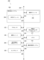
図3は、いくつかの実施形態による、眠気を催している運転者によって引き起こされるリスクを低減するために、コネクテッド車両の動作を修正するための方法300を示している。方法300のステップは、任意の順序で実行可能であり、必ずしも図3に示される順序ではない。
Exemplary Process FIG. 3 illustrates a
ステップ301において、リモート車両は、経路履歴データを含むBSMを送信する。
At
ステップ303において、自車両は、BSMを受信する。
At
ステップ305において、自車両の眠気検出システムは、BSMからBSMデータを解析する。
At
ステップ307において、眠気検出システムは、BSMデータに含まれる経路履歴データを分析する。
At
ステップ308において、眠気検出システムは、経路履歴データに示された運転パターンに基づいて、リモート車両が眠気を催している運転者によって操作されているか否かを判定するために経路履歴データを分析する。
At
ステップ309において、リモート車両が眠気を催している運転者によって操作されているとの判定に応答して、眠気検出システムは、眠気を催している運転者によって引き起こされるリスクを修正するように動作可能である改善措置(例えば、サブステップ311
またはサブステップ313)を実行する。
In
or execute sub-step 313).
サブステップ311において、自車両が非自律車両である場合、眠気検出システムは、眠気を催している運転者の存在を運転者に通知する。これは、視覚的通知(例えば、ヘッドユニットを介して)、音声通知、または視覚的通知と音声通知との組み合わせを含む。
In
サブステップ313において、自車両が自律車両である場合、眠気検出システムは、自律走行システムが、(1)自車両とリモート車両との間の距離をとること、(2)眠気を催している運転者の行動を予測するために動作可能な、異なる行動モデルをリモート車両の行動の予測に適用することと、のうちの1つ以上を含む回避行動をとることができるように、リモート車両の地理的位置(例えば、BSMデータに含まれるGPSデータに基づく。例えば図4および図5を参照)と、リモート車両の軌跡と、を表すデジタルデータを自律走行システムに提供する。眠気検出システムはまた、自車両が回避行動をとろうとしていること、およびなぜこれらの行動が生じているのかを自車両の運転者が理解できるように、自車両の運転者に視覚的通知および音声通知を提供し得る。
In
ここで図4を参照すると、いくつかの実施形態による、BSMデータ195の一例を示すブロック図が示されている。
Referring now to FIG. 4, a block diagram illustrating an example of
複数のBSMを送信するための一定の間隔は、ユーザによって設定可能であり得る。いくつかの実施形態では、この間隔のデフォルト設定は、0.1秒毎または実質的に0.1秒毎にBSMを送信することであり得る。 The regular interval for transmitting multiple BSMs may be user configurable. In some embodiments, the default setting for this interval may be to send a BSM every 0.1 seconds or substantially every 0.1 seconds.
BSMは、5.9GHzのDSRC帯域でブロードキャストされる。DSRC範囲は、実質的に1,000メートルであり得る。いくつかの実施形態では、DSRC範囲は、実質的に100メートルから実質的に1,000メートルの範囲を含み得る。DSRC範囲は、DSRC装備エンドポイント間の地形およびオクルージョンなどの変数に応じて、通常、300から500メートルである。 BSM is broadcast on the 5.9 GHz DSRC band. The DSRC range can be substantially 1,000 meters. In some embodiments, the DSRC range may include a range from substantially 100 meters to substantially 1,000 meters. The DSRC range is typically 300 to 500 meters, depending on variables such as terrain and occlusion between DSRC-equipped endpoints.
ここで図5を参照すると、いくつかの実施形態による、BSMデータ195の一例を示すブロック図が示されている。
Referring now to FIG. 5, a block diagram illustrating an example of
BSMは、2つの部分を含み得る。これら2つの部分は、図5に示すように異なるBSMデータ195を含み得る。
A BSM may include two parts. These two portions may contain
BSMデータ195のパート1は、車両のGPSデータ、車両の方位、車両の速度、車両の加速度、車両のステアリングホイール角、および車両のサイズのうちの1つ以上を表し得る。
Part 1 of
BSMデータ195のパート2は、オプションの要素のリストから引き出された可変のデータ要素セットを含むことができる。BSMのパート2に含まれるBSMデータ195のいくつかは、イベントトリガに基づいて選択され、例えば、アンチロックブレーキシステム(「ABS」)が起動されることは、車両のABSシステムに関連するBSMデータ195をトリガし得る。
Part 2 of
いくつかの実施形態では、帯域幅を節約するために、パート2のいくつかの要素は、それほど頻繁に送信されない。 In some embodiments, some elements of Part 2 are sent less frequently to conserve bandwidth.
いくつかの実施形態では、BSMに含まれるBSMデータ195は、車両の現在のスナップショットを含む。
In some embodiments, the
ここで図6Aおよび図6Bを参照すると、いくつかの実施形態による、眠気を催している運転者によって引き起こされるリスクを低減するために、コネクテッド車両の動作を修正するための方法600が示されている。
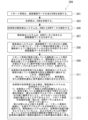
6A and 6B, a
ここで図6Aを参照すると、ステップ601において、自車両の眠気検出システムは、自車両が眠気を催している運転者によって操作されていると自車両の運転者監視システムが判定したか否かを監視する。
Referring now to FIG. 6A, at
ステップ603において、自車両の眠気検出システムは、自車両の運転者監視システムが眠気を催している運転者を検出したと判定する。
In
ステップ605において、自車両の眠気検出システムは、自車両が自動運転モードになるように、車両の自動運転システムが作動しているか否かを判定する。車両の自動運転システムが作動している場合、車両が自動運転モードであれば、眠気を催している運転者は問題にならないので、本方法はステップ601に戻る。 At step 605, the drowsiness detection system of the vehicle determines whether the vehicle's automatic driving system is operating such that the vehicle enters the automatic driving mode. If the vehicle's autonomous driving system is active, the method returns to step 601 because a drowsy driver is not a problem if the vehicle is in autonomous driving mode.
ステップ607において、自車両の眠気検出システムは、(1)自車両が眠気を催している運転者によって操作されていることと、(2)自車両が自動運転モードではないことと、を指示しているデジタルデータを、自車両によって送信されたBSMに挿入する。BSMはまた、自車両の地理的位置および自車両の軌跡を表すデジタルデータも含む。
At
ステップ608において、自車両は、BSMを送信する。
At
ステップ609において、リモート車両は、BSMを受信する。
At
ステップ611において、リモート車両の眠気検出システムは、BSMからBSMデータを解析する。
At
ステップ613において、リモート車両の眠気検出システムは、自車両が眠気を催している運転者によって操作されていると判定する。
In
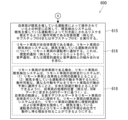
ここで図6Bを参照すると、ステップ615において、自車両が眠気を催している運転者によって操作されているとの判定に応答して、眠気検出システムは、眠気を催している運転者によって引き起こされるリスクを修正するように動作可能である改善措置(例えば、サブステップ616またはサブステップ618)を実行する。
Referring now to FIG. 6B, in
サブステップ616において、リモート車両が非自律車両である場合、リモート車両の眠気検出システムは、眠気を催している運転者の存在について、リモート車両の運転者に通知する。これは、視覚的通知(例えば、ヘッドユニットを介して)、音声通知、または視覚的通知と音声通知との組み合わせを含む。
In
サブステップ618において、リモート車両が自律車両である場合、リモート車両の眠気検出システムは、リモート車両の自律走行システムが、(1)リモート車両と自車両との間の距離をとること、(2)眠気を催している運転者の行動を予測するために動作可能な、異なる行動モデルをリモート車両の行動の予測に適用することと、を含む回避行動をとることができるように、自車両の地理的位置(例えば、BSMデータに含まれるGPSデータに基づく)と、自車両の軌跡と、を表すデジタルデータを、リモート車両の自律走行システムに提供する。リモート車両の眠気検出システムはまた、リモート車両の運転者に視覚的通知および音声通知を提供して、眠気を催している運転者の存在およびリモート
車両が予期せぬ仕方で動作し得る理由を知ることができるようにする。
In
上記の記載では、説明目的で、本明細書の完全な理解をもたらすように、多数の具体的詳細を記載した。しかし、本開示が、これらの具体的詳細なしに実施可能であることは当業者には明らかとなるだろう。幾つかの例では、説明を分かりにくくすることを避けるために、構造及びデバイスをブロック図形式で示している。例えば、本実施形態は、主にユーザインタフェース及び特定のハードウェアに関連して、上記で説明することができる。しかし、本実施形態は、データ及びコマンドを受信することができる、どのような種類のコンピュータシステムにも、及びサービスを提供するどのような周辺デバイスにも適用することができる。 In the above description, for purposes of explanation, numerous specific details are set forth in order to provide a thorough understanding of the specification. However, it will be apparent to those skilled in the art that the present disclosure may be practiced without these specific details. In some instances, structures and devices are shown in block diagram form in order to avoid obscuring the description. For example, the present embodiments may be described above primarily in terms of user interfaces and specific hardware. However, the present embodiments are applicable to any kind of computer system and any peripheral device that provides services capable of receiving data and commands.
本明細書における「幾つかの実施形態」又は「幾つかの例」への言及は、実施形態又は例に関連して記載したある特定の特徴、構造、又は特性が、記載の少なくとも1つの実施形態に含まれ得ることを意味する。本明細書の様々な箇所における「幾つかの実施形態では」というフレーズの出現は、必ずしも全て同じ実施形態に言及しているわけではない。 References herein to "some embodiments" or "some examples" mean that a particular feature, structure, or characteristic described in connection with an embodiment or example It means that it can be included in the form. The appearances of the phrase "in some embodiments" in various places in this specification are not necessarily all referring to the same embodiment.
以下の詳細な記載の幾つかの部分は、コンピュータメモリ内のデータビットに対する演算のアルゴリズム及び記号表現の観点から提示される。これらのアルゴリズム的記述及び表現は、データ処理分野の当業者によって、最も効果的に自身の研究の内容を他の当業者に伝えるために使用される手段である。アルゴリズムは、ここでは、及び一般的に、所望の結果をもたらす、セルフコンシステントな一連のステップであると考えられる。これらのステップは、物理量の物理的操作を必要とするものである。一般に、必ずではないが、これらの量は、保存、転送、結合、比較、及びその他の操作が行われることが可能な電気又は磁気信号の形をとる。時には、主に一般的な用法が理由で、ビット、値、要素、記号、文字、用語、又は数字などとして、これらの信号に言及することが便利であると分かっている。 Some portions of the detailed descriptions that follow are presented in terms of algorithms and symbolic representations of operations on data bits within a computer memory. These algorithmic descriptions and representations are the means used by those skilled in the data processing arts to most effectively convey the substance of their work to others skilled in the art. An algorithm is considered here, and generally, to be a self-consistent sequence of steps leading to a desired result. These steps are those requiring physical manipulations of physical quantities. Usually, though not necessarily, these quantities take the form of electrical or magnetic signals capable of being stored, transferred, combined, compared, and otherwise manipulated. It has proven convenient at times, principally for reasons of common usage, to refer to these signals as bits, values, elements, symbols, characters, terms, numbers, or the like.
しかし、これら及び類似の用語の全てが、適切な物理量と関連付けられるべきであること、及びこれらの量に適用される便利なラベルにすぎないことが留意されるべきである。具体的な別段の記載のない限り、以下の記述から明らかなように、記載全体を通して、「処理する」、「算出する」、「計算する」、「決定する」、又は「表示する」などを含む用語を利用した記述は、コンピュータシステムのレジスタ及びメモリ内で物理(電子)量として表されるデータを、コンピュータシステムのメモリ又はレジスタ、又は他のそのような情報ストレージ、送信、又はディスプレイデバイス内で同様に物理量として表される他のデータへと操作及び変換する、コンピュータシステム又は類似の電子コンピューティングデバイスのアクション及びプロセスを指す。 It should be noted, however, that all of these and similar terms are to be associated with the appropriate physical quantities and are merely convenient labels applied to these quantities. Unless specifically stated otherwise, words such as "process," "calculate," "calculate," "determine," or "display" are used throughout the description as will be apparent from the description below. Descriptions using terms that include data represented as physical (electronic) quantities within the registers and memory of a computer system, within the memory or registers of a computer system, or other such information storage, transmission, or display device Refers to the actions and processes of a computer system or similar electronic computing device that manipulates and transforms data into other data that are likewise represented as physical quantities.
本明細書の本実施形態はまた、本明細書における動作を行うための装置に関してもよい。この装置は、必要とされる目的のために特別に構築されてもよく、又はコンピュータに保存されたコンピュータプログラムによって選択的に作動又は再設定される汎用コンピュータを含んでいてもよい。このようなコンピュータプログラムは、限定されないが、フロッピーディスク、光ディスク、CD-ROM、及び磁気ディスクを含むあらゆる種類のディスク、読取り専用メモリ(ROM)、ランダムアクセスメモリ(RAM)、EPROM、EEPROM、磁気又は光カード、不揮発性メモリを備えたUSBキーを含むフラッシュメモリ、又はそれぞれコンピュータシステムバスに結合された電子命令を保存するのに適したあらゆる種類の媒体を含む、コンピュータ可読ストレージ媒体に保存されてもよい。 The embodiments herein may also relate to apparatus for performing the operations herein. This apparatus may be specially constructed for the required purposes, or it may comprise a general purpose computer selectively activated or reconfigured by a computer program stored in the computer. Such computer programs may be any kind of disk including, but not limited to, floppy disk, optical disk, CD-ROM and magnetic disk, read only memory (ROM), random access memory (RAM), EPROM, EEPROM, magnetic or stored on a computer readable storage medium including optical cards, flash memory including USB keys with non-volatile memory, or any type of medium suitable for storing electronic instructions each coupled to a computer system bus; good.
本明細書は、幾つかの完全なハードウェア実施形態、幾つかの完全なソフトウェア実施形態、又はハードウェア及びソフトウェア要素の両方を含有した幾つかの実施形態の形を
とり得る。幾つかの好ましい実施形態では、本明細書は、限定されないが、ファームウェア、常駐ソフトウェア、マイクロコードなどを含むソフトウェアで実施される。
This specification may take the form of some entirely hardware embodiments, some entirely software embodiments, or several embodiments containing both hardware and software elements. In some preferred embodiments, the specification is implemented in software, including but not limited to firmware, resident software, microcode, and the like.
さらに、記載は、コンピュータ又は任意の命令実行システムによって、又は関連して使用されるプログラムコードを提供するコンピュータ使用可能又はコンピュータ可読媒体からアクセス可能なコンピュータプログラム製品の形をとり得る。この記載を目的として、コンピュータ使用可能又はコンピュータ可読媒体は、命令実行システム、装置、又はデバイスによって、又は関連して使用されるプログラムの含有、保存、伝達、伝搬、又は伝送を行うことができる、どのような装置でもよい。 Furthermore, the description may take the form of a computer program product accessible from a computer-usable or computer-readable medium providing program code for use by or in connection with a computer or any instruction execution system. For the purposes of this description, any computer-usable or computer-readable medium is capable of containing, storing, transmitting, propagating, or transmitting a program for use by or in connection with an instruction execution system, apparatus, or device; Any device will do.
プログラムコードの保存又は実行に適したデータ処理システムは、システムバスによってメモリ素子と直接的又は間接的に結合された少なくとも1つのプロセッサを含む。メモリ素子は、プログラムコードの実際の実行中に用いられるローカルメモリ、大容量ストレージ、及び実行中に大容量ストレージからコードが抽出されなければならない回数を減らすために少なくとも一部のプログラムコードの一時的ストレージを提供するキャッシュメモリを含み得る。 A data processing system suitable for storing and executing program code will include at least one processor coupled directly or indirectly to memory elements through a system bus. Memory elements include local memory used during actual execution of the program code, mass storage, and temporary storage of at least a portion of the program code to reduce the number of times the code must be extracted from the mass storage during execution. A cache memory that provides storage may be included.
入出力又はI/Oデバイス(限定されないが、キーボード、ディスプレイ、ポインティングデバイスなどを含む)は、システムに直接的に、又は介在するI/Oコントローラを通して結合され得る。 Input/output or I/O devices (including but not limited to keyboards, displays, pointing devices, etc.) can be coupled to the system either directly or through intervening I/O controllers.
ネットワークアダプタは、データ処理システムが、介在する私設又は公衆ネットワークを通して他のデータ処理システム、リモートプリンタ、又はストレージデバイスに結合されることを可能にするために、システムに結合されてもよい。モデム、ケーブルモデム、及びイーサネットカードは、現在利用可能なネットワークアダプタの種類のほんの数例である。 Network adapters may be coupled to the system to enable the data processing system to become coupled to other data processing systems, remote printers, or storage devices through intervening private or public networks. Modems, cable modems, and Ethernet cards are just a few of the types of network adapters currently available.
最後に、本明細書に提示するアルゴリズム及びディスプレイは、どの特定のコンピュータ又は他の装置とも本質的に関連していない。本明細書の教示に従って、様々な汎用システムをプログラムと共に使用することができ、又は必要な方法ステップを行うように、より専門化された装置を構築することが便利であると判明する場合がある。様々なこれらのシステムのために必要な構造は、以下の記載から分かるだろう。加えて、本明細書は、特定のプログラミング言語に関連して記載されていない。様々なプログラミング言語を使用して、ここに記載される本明細書の教示を実施することができることが認識されるだろう。 Finally, the algorithms and displays presented herein are not inherently related to any particular computer or other apparatus. Various general-purpose systems may be used with programs in accordance with the teachings herein, or it may prove convenient to construct a more specialized apparatus to perform the required method steps. . The required structure for a variety of these systems will appear from the description below. Additionally, the specification is not written with reference to any particular programming language. It will be appreciated that a variety of programming languages may be used to implement the teachings described herein.
本明細書の実施形態の上記の記載は、例示及び説明を目的として提示されたものである。包括的であること、又は開示した正確な形態に本明細書を限定することを意図したものではない。上記の教示に鑑みて、多くの変更形態及び変形形態が可能である。本開示の範囲が、この詳細な説明によってではなく、本出願の特許請求の範囲によって限定されることが意図される。当該分野に精通する者には理解されるように、本明細書は、その精神又は必須の特性から逸脱することなく、他の特定の形態で具現化されてもよい。同様に、モジュール、ルーチン、特徴、属性、手法、及び他の態様の特定の命名及び区分は、義務的又は重要なものではなく、本明細書又はその特徴を実施する機構は、異なる名称、区分、又は形式を有していてもよい。さらに、関連技術の当業者には明らかとなるように、本開示のモジュール、ルーチン、特徴、属性、手法、及び他の態様は、ソフトウェア、ハードウェア、ファームウェア、又はこれら3つの任意の組み合わせとして実施することができる。また、本明細書のコンポーネント(その一例は、モジュールである)がソフトウェアとして実施される場合はいつでも、そのコンポーネントは、スタンドアロンプログラムとして、より大きなプログラムの一部として、複数の別個のプログラムとして、静的又は動
的にリンクしたライブラリとして、カーネルロード可能モジュールとして、デバイスドライバとして、又はコンピュータプログラミング分野の当業者に現在又は将来公知のあらゆる及びその他の方法で実施することができる。加えて、本開示は、どの特定のプログラミング言語の実施形態にも、又はどの特定のオペレーティングシステム又は動作環境の実施形態にも決して限定されない。従って、本開示は、以下の特許請求の範囲に記載される本明細書の範囲を説明するものであって、限定するものではないことが意図される。
The foregoing descriptions of embodiments herein have been presented for purposes of illustration and description. It is not intended to be exhaustive or to limit the specification to the precise forms disclosed. Many modifications and variations are possible in light of the above teachings. It is intended that the scope of the disclosure be limited not by this detailed description, but rather by the claims of this application. As will be understood by those skilled in the art, the specification may be embodied in other specific forms without departing from the spirit or essential characteristics thereof. Likewise, the particular naming and categorization of modules, routines, features, attributes, techniques, and other aspects is not mandatory or essential, and the specification or mechanisms implementing its features may be referred to by different names, categorizations, or , or may have the form Moreover, modules, routines, features, attributes, techniques, and other aspects of the present disclosure may be implemented as software, hardware, firmware, or any combination of the three, as will be apparent to those skilled in the relevant arts. can do. Also, whenever a component of the specification (an example of which is a module) is implemented as software, that component may be implemented as a standalone program, as part of a larger program, as multiple separate programs, or as a static program. It can be implemented as a dynamically or dynamically linked library, as a kernel loadable module, as a device driver, or in any and all other ways now or in the future known to those of ordinary skill in the computer programming arts. Additionally, this disclosure is in no way limited to any particular programming language implementation, or to any particular operating system or operating environment implementation. Accordingly, this disclosure is intended to be illustrative, not limiting, of the scope herein, which is set forth in the following claims.
Claims (7)
前記第2の運転者が眠気を催しており、かつ、前記第2のコネクテッド車両が自動運転中でない場合に、前記第2のコネクテッド車両が、前記第2の運転者の眠気を通知するV2Xメッセージを送信することと、
第1のコネクテッド車両が、前記第2のコネクテッド車両から送信されたV2Xメッセージを受信することと、
前記第1のコネクテッド車両が、自車両が自律車両であるか否かを判定することと、
前記第1のコネクテッド車両が自律車両でなく、前記第1のコネクテッド車両が前記第2の運転者の眠気を通知する前記V2Xメッセージを受信したことに応答して、前記第1のコネクテッド車両が、前記第1のコネクテッド車両の第1の運転者に通知を提供することと、
前記第1のコネクテッド車両が自律車両であり、前記第1のコネクテッド車両が前記第2の運転者の眠気を通知する前記V2Xメッセージを受信したことに応答して、前記第2の運転者によって引き起こされるリスクを低減させるため、前記第1のコネクテッド車両が前記第2のコネクテッド車両を回避するための回避操作を自動的に行うことと、
を含む、方法。 a second connected vehicle determining that a second driver of the second connected vehicle is drowsy;
A V2X message in which the second connected vehicle notifies the second driver of drowsiness when the second driver is drowsy and the second connected vehicle is not driving automatically. and
a first connected vehicle receiving a V2X message transmitted from the second connected vehicle;
determining whether the first connected vehicle is an autonomous vehicle;
In response to the first connected vehicle not being an autonomous vehicle and the first connected vehicle receiving the V2X message notifying the second driver of drowsiness, the first connected vehicle: providing a notification to a first driver of the first connected vehicle;
The first connected vehicle is an autonomous vehicle, and the first connected vehicle is triggered by the second driver in response to receiving the V2X message notifying the second driver of drowsiness. In order to reduce the risk of being caught, the first connected vehicle automatically performs an avoidance operation to avoid the second connected vehicle;
A method, including
請求項1に記載の方法。 the V2X message is a dedicated short range communication (DSRC) message;
The method of claim 1.
請求項1に記載の方法。 the V2X message is not one of a Wi-Fi message, a 3G message, a 4G message, a 5G message, a Long Term Evolution (LTE) message, a millimeter wave communication message, a Bluetooth message, and a satellite communication;
The method of claim 1.
請求項1に記載の方法。 wherein the V2X message is a basic safety message (BSM);
The method of claim 1.
くともいずれかである、
請求項1に記載の方法。 the notification is at least one of a visual notification displayed on the head unit and an audio notification;
The method of claim 1.
前記第2のコンピュータコードは、
前記第2のコネクテッド車両の第2の運転者が眠気を催していると判定することと、
前記第2の運転者が眠気を催しており、かつ、前記第2のコネクテッド車両が自動運転中でない場合に、前記第2の運転者の眠気を通知するV2Xメッセージを送信することと、
を、前記第2のプロセッサに実行させ、
前記第1のコンピュータコードは、
前記第2のコネクテッド車両から送信されたV2Xメッセージを受信することと、
自車両が自律車両であるか否かを判定することと、
前記第1のコネクテッド車両が自律車両でなく、前記第1のコネクテッド車両が前記第2の運転者の眠気を通知する前記V2Xメッセージを受信したことに応答して、前記第1のコネクテッド車両の第1の運転者に通知を提供することと、
前記第1のコネクテッド車両が自律車両であり、前記第1のコネクテッド車両が前記第2の運転者の眠気を通知する前記V2Xメッセージを受信したことに応答して、前記第2の運転者によって引き起こされるリスクを低減させるため、前記第2のコネクテッド車両を回避するための回避操作を自動的に行うことと、
を、前記第1のプロセッサに実行させる、
システム。 a first processor of a first connected vehicle; a first non-transitory memory communicatively connected to the first processor and storing a first computer code; and a second processor of a second connected vehicle. A system comprising a processor and a second non-transitory memory communicatively coupled to the second processor and storing a second computer code, comprising:
The second computer code comprises:
determining that a second driver of the second connected vehicle is drowsy;
If the second driver is drowsy and the second connected vehicle is not driving automatically, sending a V2X message notifying the second driver of drowsiness;
causing the second processor to execute
The first computer code comprises:
receiving a V2X message transmitted from the second connected vehicle;
Determining whether the own vehicle is an autonomous vehicle;
in response to the first connected vehicle not being an autonomous vehicle and the first connected vehicle receiving the V2X message notifying the second driver of drowsiness; providing a notification to a driver of 1;
The first connected vehicle is an autonomous vehicle, and the first connected vehicle is triggered by the second driver in response to receiving the V2X message notifying the second driver of drowsiness. Automatically performing an avoidance operation to avoid the second connected vehicle in order to reduce the risk of being caught;
causes the first processor to execute
system.
請求項6に記載のシステム。 the notification is at least one of a visual notification displayed on the head unit and an audio notification;
7. A system according to claim 6 .
Applications Claiming Priority (2)
| Application Number | Priority Date | Filing Date | Title |
|---|---|---|---|
| US16/018,972 | 2018-06-26 | ||
| US16/018,972 US10796175B2 (en) | 2018-06-26 | 2018-06-26 | Detection of a drowsy driver based on vehicle-to-everything communications |
Publications (3)
| Publication Number | Publication Date |
|---|---|
| JP2020030806A JP2020030806A (en) | 2020-02-27 |
| JP2020030806A5 JP2020030806A5 (en) | 2022-05-11 |
| JP7318360B2 true JP7318360B2 (en) | 2023-08-01 |
Family
ID=66857717
Family Applications (1)
| Application Number | Title | Priority Date | Filing Date |
|---|---|---|---|
| JP2019118632A Active JP7318360B2 (en) | 2018-06-26 | 2019-06-26 | Drowsy Driver Detection Based on Vehicle-to-Thing Communication |
Country Status (4)
| Country | Link |
|---|---|
| US (1) | US10796175B2 (en) |
| EP (1) | EP3588459A1 (en) |
| JP (1) | JP7318360B2 (en) |
| CN (1) | CN110712649A (en) |
Families Citing this family (10)
| Publication number | Priority date | Publication date | Assignee | Title |
|---|---|---|---|---|
| JP2020005185A (en) * | 2018-06-29 | 2020-01-09 | ルネサスエレクトロニクス株式会社 | Communication device |
| US10989554B2 (en) * | 2018-08-24 | 2021-04-27 | Honda Motor Co., Ltd. | System and method for emotion navigation routing |
| KR102529919B1 (en) * | 2018-11-28 | 2023-05-08 | 현대자동차주식회사 | Apparatus, system and method for managing drowsy driving |
| US10966068B2 (en) * | 2019-01-06 | 2021-03-30 | Palo Alto Innovation, LLC | User-configurable sensor platform |
| IT201900000133A1 (en) | 2019-01-07 | 2020-07-07 | St Microelectronics Srl | "Image processing process, corresponding system, vehicle and IT product" |
| JP7232094B2 (en) * | 2019-03-25 | 2023-03-02 | 株式会社Subaru | VEHICLE CONTROL DEVICE, VEHICLE CONTROL METHOD AND PROGRAM |
| KR20200131640A (en) * | 2019-05-14 | 2020-11-24 | 현대자동차주식회사 | Vehicle and method for controlling thereof |
| TWI737051B (en) * | 2019-11-28 | 2021-08-21 | 啓碁科技股份有限公司 | Vehicle warning method, telematics control unit and device based on vehicle (v2x) communications |
| CN112071061B (en) * | 2020-09-11 | 2021-10-15 | 武汉云上融媒科技有限公司 | Vehicle service system based on cloud computing and data analysis |
| US11767021B2 (en) | 2021-09-15 | 2023-09-26 | Toyota Research Institute, Inc. | Systems and methods for remotely assisting an operator |
Citations (4)
| Publication number | Priority date | Publication date | Assignee | Title |
|---|---|---|---|---|
| JP2004220348A (en) | 2003-01-15 | 2004-08-05 | Nissan Motor Co Ltd | Vehicle running condition detection system and vehicle running control device |
| JP2010182236A (en) | 2009-02-09 | 2010-08-19 | Toyota Motor Corp | Movement region prediction apparatus |
| JP2017200791A (en) | 2016-05-02 | 2017-11-09 | 富士通テン株式会社 | Occupant protection device and occupant protection method |
| JP2017228286A (en) | 2016-06-20 | 2017-12-28 | トヨタ自動車株式会社 | Traffic obstacle notification system based on wireless vehicle data |
Family Cites Families (18)
| Publication number | Priority date | Publication date | Assignee | Title |
|---|---|---|---|---|
| JP2008023086A (en) | 2006-07-21 | 2008-02-07 | Hino Motors Ltd | Vigilance detector |
| US20110106442A1 (en) | 2009-10-30 | 2011-05-05 | Indian Institute Of Technology Bombay | Collision avoidance system and method |
| DE112012006975T5 (en) * | 2012-10-04 | 2015-08-06 | Mitsubishi Electric Corporation | Vehicle onboard information processing device |
| US9751534B2 (en) | 2013-03-15 | 2017-09-05 | Honda Motor Co., Ltd. | System and method for responding to driver state |
| US20160321924A1 (en) * | 2015-05-01 | 2016-11-03 | Hyundai America Technical Center, Inc. | Predictive road hazard identification system |
| US10553112B2 (en) * | 2015-08-19 | 2020-02-04 | Qualcomm Incorporated | Safety event message transmission timing in dedicated short-range communication (DSRC) |
| US10358143B2 (en) * | 2015-09-01 | 2019-07-23 | Ford Global Technologies, Llc | Aberrant driver classification and reporting |
| US9959763B2 (en) | 2016-01-08 | 2018-05-01 | Ford Global Technologies, Llc | System and method for coordinating V2X and standard vehicles |
| CA3014660C (en) * | 2016-02-15 | 2021-08-17 | Allstate Insurance Company | Early notification of non-autonomous area |
| US9688288B1 (en) * | 2016-03-08 | 2017-06-27 | VOLKSWAGEN AG et al. | Geofencing for auto drive route planning |
| JP6552992B2 (en) * | 2016-03-17 | 2019-07-31 | 株式会社東芝 | Information processing apparatus, in-vehicle apparatus, and information processing method |
| US20170276504A1 (en) * | 2016-03-22 | 2017-09-28 | Toyota Jidosha Kabushiki Kaisha | Vehicular Traffic Assistance Based on Traffic Management Decisions |
| US10309789B2 (en) * | 2016-03-25 | 2019-06-04 | Qualcomm Incorporated | Automated lane assignment for vehicles |
| US9956963B2 (en) * | 2016-06-08 | 2018-05-01 | GM Global Technology Operations LLC | Apparatus for assessing, predicting, and responding to driver fatigue and drowsiness levels |
| US10269242B2 (en) * | 2016-07-12 | 2019-04-23 | Ford Global Technologies, Llc | Autonomous police vehicle |
| US10281925B2 (en) * | 2016-10-21 | 2019-05-07 | Toyota Jidosha Kabushiki Kaisha | Estimate of geographical position of a vehicle using wireless vehicle data |
| US10852728B2 (en) * | 2017-12-27 | 2020-12-01 | Intel Corporation | Remote driver state consideration for autonomous vehicles |
| US11079241B2 (en) * | 2017-12-29 | 2021-08-03 | Intel Corporation | Detection of GPS spoofing based on non-location data |
-
2018
- 2018-06-26 US US16/018,972 patent/US10796175B2/en active Active
-
2019
- 2019-06-13 EP EP19179875.0A patent/EP3588459A1/en active Pending
- 2019-06-26 CN CN201910557676.3A patent/CN110712649A/en active Pending
- 2019-06-26 JP JP2019118632A patent/JP7318360B2/en active Active
Patent Citations (4)
| Publication number | Priority date | Publication date | Assignee | Title |
|---|---|---|---|---|
| JP2004220348A (en) | 2003-01-15 | 2004-08-05 | Nissan Motor Co Ltd | Vehicle running condition detection system and vehicle running control device |
| JP2010182236A (en) | 2009-02-09 | 2010-08-19 | Toyota Motor Corp | Movement region prediction apparatus |
| JP2017200791A (en) | 2016-05-02 | 2017-11-09 | 富士通テン株式会社 | Occupant protection device and occupant protection method |
| JP2017228286A (en) | 2016-06-20 | 2017-12-28 | トヨタ自動車株式会社 | Traffic obstacle notification system based on wireless vehicle data |
Also Published As
| Publication number | Publication date |
|---|---|
| US20190392235A1 (en) | 2019-12-26 |
| US10796175B2 (en) | 2020-10-06 |
| JP2020030806A (en) | 2020-02-27 |
| CN110712649A (en) | 2020-01-21 |
| EP3588459A1 (en) | 2020-01-01 |
Similar Documents
| Publication | Publication Date | Title |
|---|---|---|
| JP7318360B2 (en) | Drowsy Driver Detection Based on Vehicle-to-Thing Communication | |
| US10789848B2 (en) | Multi-level hybrid vehicle-to-anything communications for cooperative perception | |
| JP7124816B2 (en) | Modification of vehicle components based on vehicle accident reconstruction data | |
| JP7413811B2 (en) | Modification of vehicle components based on Vehicle-to-Everything communication | |
| US10248410B2 (en) | Implementation decision to provide ADAS function update for a vehicle | |
| CN111554119B (en) | Method for a host vehicle and system for a host vehicle | |
| US11697410B2 (en) | Vehicle-to-everything communication-based lane change collision avoidance warning | |
| US10762363B2 (en) | Road sign recognition for connected vehicles | |
| JP2020021470A (en) | Selection of vehicle for improving flight range and assistance of flight drone in approaching | |
| JP7172879B2 (en) | Reduced Adjacent Channel Interference for Wireless Vehicle Messages | |
| US20190283709A1 (en) | Theft deterrent system for connected vehicles based on wireless messages | |
| US20200307580A1 (en) | Proactive message transmitter identification system | |
| JP7351164B2 (en) | V2X full-duplex localization support for V2X receivers | |
| JP7078022B2 (en) | Context system to improve understanding of V2X communication by V2X receiver | |
| EP3565286B1 (en) | Disaster mitigation system for connected vehicles having hidden vehicle functionality | |
| CN111824134A (en) | Adjustable blind spot monitor |
Legal Events
| Date | Code | Title | Description |
|---|---|---|---|
| A521 | Request for written amendment filed |
Free format text: JAPANESE INTERMEDIATE CODE: A523 Effective date: 20191025 |
|
| A521 | Request for written amendment filed |
Free format text: JAPANESE INTERMEDIATE CODE: A523 Effective date: 20220427 |
|
| A621 | Written request for application examination |
Free format text: JAPANESE INTERMEDIATE CODE: A621 Effective date: 20220427 |
|
| A977 | Report on retrieval |
Free format text: JAPANESE INTERMEDIATE CODE: A971007 Effective date: 20230215 |
|
| A131 | Notification of reasons for refusal |
Free format text: JAPANESE INTERMEDIATE CODE: A131 Effective date: 20230221 |
|
| A521 | Request for written amendment filed |
Free format text: JAPANESE INTERMEDIATE CODE: A523 Effective date: 20230417 |
|
| TRDD | Decision of grant or rejection written | ||
| A01 | Written decision to grant a patent or to grant a registration (utility model) |
Free format text: JAPANESE INTERMEDIATE CODE: A01 Effective date: 20230620 |
|
| A61 | First payment of annual fees (during grant procedure) |
Free format text: JAPANESE INTERMEDIATE CODE: A61 Effective date: 20230703 |
|
| R151 | Written notification of patent or utility model registration |
Ref document number: 7318360 Country of ref document: JP Free format text: JAPANESE INTERMEDIATE CODE: R151 |