JP2017197197A - Replenishing container and ink jet recording device having the same - Google Patents

Replenishing container and ink jet recording device having the same Download PDF

Info

Publication number
JP2017197197A
JP2017197197A JP2016086725A JP2016086725A JP2017197197A JP 2017197197 A JP2017197197 A JP 2017197197A JP 2016086725 A JP2016086725 A JP 2016086725A JP 2016086725 A JP2016086725 A JP 2016086725A JP 2017197197 A JP2017197197 A JP 2017197197A
Authority
JP
Japan
Prior art keywords
supply container
ink
cylindrical portion
hole
storage
Prior art date
Legal status (The legal status is an assumption and is not a legal conclusion. Google has not performed a legal analysis and makes no representation as to the accuracy of the status listed.)
Pending
Application number
JP2016086725A
Other languages
Japanese (ja)
Inventor
雄彦 松下
Katsuhiko Matsushita
雄彦 松下
直倫 吉田
Naomichi Yoshida
直倫 吉田
宮尾 明
Akira Miyao
明 宮尾
Current Assignee (The listed assignees may be inaccurate. Google has not performed a legal analysis and makes no representation or warranty as to the accuracy of the list.)
Hitachi Industrial Equipment Systems Co Ltd
Original Assignee
Hitachi Industrial Equipment Systems Co Ltd
Priority date (The priority date is an assumption and is not a legal conclusion. Google has not performed a legal analysis and makes no representation as to the accuracy of the date listed.)
Filing date
Publication date
Application filed by Hitachi Industrial Equipment Systems Co Ltd filed Critical Hitachi Industrial Equipment Systems Co Ltd
Priority to JP2016086725A priority Critical patent/JP2017197197A/en
Priority to CN201710203011.3A priority patent/CN107303759B/en
Publication of JP2017197197A publication Critical patent/JP2017197197A/en
Pending legal-status Critical Current

Links

Images

Classifications

    • BPERFORMING OPERATIONS; TRANSPORTING
    • B41PRINTING; LINING MACHINES; TYPEWRITERS; STAMPS
    • B41JTYPEWRITERS; SELECTIVE PRINTING MECHANISMS, i.e. MECHANISMS PRINTING OTHERWISE THAN FROM A FORME; CORRECTION OF TYPOGRAPHICAL ERRORS
    • B41J2/00Typewriters or selective printing mechanisms characterised by the printing or marking process for which they are designed
    • B41J2/005Typewriters or selective printing mechanisms characterised by the printing or marking process for which they are designed characterised by bringing liquid or particles selectively into contact with a printing material
    • B41J2/01Ink jet
    • B41J2/17Ink jet characterised by ink handling
    • B41J2/175Ink supply systems ; Circuit parts therefor
    • B41J2/17503Ink cartridges
    • B41J2/17553Outer structure

Landscapes

  • Ink Jet (AREA)
  • Closures For Containers (AREA)
  • Gasket Seals (AREA)
  • Pressure Vessels And Lids Thereof (AREA)
  • Particle Formation And Scattering Control In Inkjet Printers (AREA)
  • Wet Developing In Electrophotography (AREA)

Abstract

PROBLEM TO BE SOLVED: To solve the problem in which, because rubber such as butyl rubber or ethylene propylene rubber formed into a cylindrical shape having a through hole is used as a sealing member, in order to form a through hole, a punch for hole punching, a hole punching step, inspection of burrs generated in a punched part of the hole, a removing step thereof, and the like are required, thereby causing an increase in manufacturing cost.SOLUTION: A replenishing container comprises: a storage member having a storage chamber for storing a liquid, in which an opening is formed; a plug member for sealing the opening of the storage member; a lid member covering the plug member; and a seal member provided between the plug member and the lid member. The seal member has a cylindrical part and a bottom part closing a hole inside the cylindrical part. The lid member has a through hole formed concentrically with the cylindrical part of the seal member. The inner diameter of a part or the whole of a through hole of the seal member is smaller than the inner diameter of the through hole of the lid member.SELECTED DRAWING: Figure 1

Description

本発明は、補給容器及びこれを備えたインクジェット記録装置に関するものである。 The present invention relates to a replenishing container and an ink jet recording apparatus including the same.

本技術分野の背景技術として、特許文献1(国際公開第2015−079547号公報)がある。この公報には、「シール部材314は貫通穴361を有した円筒状であり、シール部材314の貫通穴361の内側面には2個の環状突起362、363が備えられ、環状突起362、363は貫通穴361と同心状に形成されており、また第1の蓋部材313の貫通穴353と同心状に配置されている。」と記載されている。  As background art of this technical field, there is Patent Document 1 (International Publication No. 2015-079547). According to this publication, “the seal member 314 has a cylindrical shape having a through hole 361, and two annular protrusions 362 and 363 are provided on the inner surface of the through hole 361 of the seal member 314, and the annular protrusions 362 and 363 are provided. Is formed concentrically with the through hole 361 and is arranged concentrically with the through hole 353 of the first lid member 313.

また、実施例として、「また、シール部材314には弾性体であるブチルゴムあるいはエチレンプロピレンゴムが用いられ、液体吸収材315には連続気泡のポリオレフィン系発泡体あるいはポリオレフィン不織布が用いられる。なお、上記材質は本実施例における好適なものであり、他のものを用いてもよい。」と記載されている。   As an example, “an elastic butyl rubber or ethylene propylene rubber is used for the seal member 314, and an open-cell polyolefin foam or a polyolefin nonwoven fabric is used for the liquid absorbent 315. The material is suitable for this embodiment, and other materials may be used. "

国際公開第2015−079547号公報International Publication No. 2015-0779547

特許文献1では、インクあるいは溶剤補給時にインクあるいは溶剤による汚れを低減可能な補給容器及びインクジェット記録装置を提供することを目的として、上述の構成をとるものと記載されている。しかしながら、上述の構成では、シール部材としてブチルゴムやエチレンプロピレンゴムなどのゴムが貫通穴を有した円筒状に成形されたものが用いられており、貫通穴を形成するために、通常、穴打ち抜き用のポンチや穴打ち抜き工程、穴の打ち抜き部に発生するバリの検査、除去工程などが必要となり、製造コストを高くする要因となっていた。   In Patent Document 1, it is described that the above-described configuration is taken for the purpose of providing a replenishment container and an ink jet recording apparatus capable of reducing contamination due to ink or solvent when ink or solvent is replenished. However, in the above configuration, a rubber member such as butyl rubber or ethylene propylene rubber formed into a cylindrical shape having a through hole is used as the seal member. This requires a punching and punching process, an inspection and removal process for burrs generated in the punched part of the hole, and the manufacturing cost is increased.

上記課題を解決するために、例えば特許請求の範囲に記載の構成を採用する。   In order to solve the above problems, for example, the configuration described in the claims is adopted.

本願は上記課題を解決する手段を複数含んでいるが、その一例を挙げるならば、液体を貯蔵する貯蔵室を有し、開口部が形成された貯蔵部材と、前記貯蔵部材の開口部を封止する栓部材と、前記栓部材を覆う蓋部材と、前記栓部材と前記蓋部材の間に備えられたシール部材とを有し、前記シール部材は円筒部と円筒部の内側の穴を塞ぐ底部を有し、前記蓋部材は、前記シール部材の円筒部と同心状に空けられた貫通穴を有し、前記シール部材の貫通穴の一部あるいは全部の内径は前記蓋部材の貫通穴の内径より小さいことを特徴とする。   The present application includes a plurality of means for solving the above problems. For example, a storage member having a storage chamber for storing a liquid and having an opening formed therein and the opening of the storage member are sealed. A stopper member that covers the stopper member; a sealing member provided between the stopper member and the lid member; and the sealing member closes a hole inside the cylindrical portion and the cylindrical portion. The lid member has a through hole concentrically formed with the cylindrical portion of the seal member, and the inner diameter of a part or all of the through hole of the seal member is equal to the through hole of the lid member. It is smaller than the inner diameter.

本発明によれば、インクあるいは溶剤補給時等にインクあるいは溶剤による汚れを低減可能な補給容器及びこれを備えたインクジェット記録装置を、より低コストで提供することができる。   ADVANTAGE OF THE INVENTION According to this invention, the replenishment container which can reduce the stain | pollution | contamination by an ink or a solvent at the time of ink or solvent replenishment, and an inkjet recording device provided with this can be provided at lower cost.

実施例1にかかるインク補給容器の全体構造を示す断面図である。1 is a cross-sectional view illustrating the overall structure of an ink supply container according to Example 1. FIG. 実施例1にかかる補給容器を搭載するインクジェット記録装置を示す全体図である。1 is an overall view showing an ink jet recording apparatus equipped with a supply container according to Embodiment 1. FIG. 実施例1にかかる補給容器が搭載されるインクジェット記録装置の実使用状態の一例を示す図である。It is a figure which shows an example of the actual use state of the inkjet recording device with which the supply container concerning Example 1 is mounted. 実施例1にかかる補給容器が搭載されるインクジェット記録装置の制御構成を示す図である。It is a figure which shows the control structure of the inkjet recording device with which the supply container concerning Example 1 is mounted. 実施例1にかかる補給容器が搭載されるインクジェット記録装置のインク循環システムの系統図である。1 is a system diagram of an ink circulation system of an ink jet recording apparatus on which a supply container according to Example 1 is mounted. 実施例1にかかる補給容器が搭載されるインクジェット記録装置においてインクサブ容器の液面制御フローの一例を示す図である。FIG. 5 is a diagram illustrating an example of a liquid level control flow of an ink sub-container in an ink jet recording apparatus in which a replenishing container according to Example 1 is mounted. 実施例1にかかる補給容器が搭載されるインクジェット記録装置のインク循環エリアの概観図である。1 is an overview of an ink circulation area of an ink jet recording apparatus in which a supply container according to Example 1 is mounted. 実施例1にかかる補給容器の栓部材の一例を示す図である。It is a figure which shows an example of the stopper member of the replenishment container concerning Example 1. FIG. 実施例1にかかる補給容器の第1の蓋部材の一例を示す図である。It is a figure which shows an example of the 1st cover member of the supply container concerning Example 1. FIG. 実施例1にかかる補給容器の一例を示す図である。It is a figure which shows an example of the supply container concerning Example 1. FIG. 実施例1にかかる補給容器の液吸収材の一例を示す図である。It is a figure which shows an example of the liquid absorber of the replenishment container concerning Example 1. FIG. 実施例1にかかるインク補給容器の一例を示す図である。6 is a diagram illustrating an example of an ink supply container according to Embodiment 1. FIG. 実施例1にかかる補給容器が搭載されるインクジェット記録装置のインクサブ容器の一例を示す図である。FIG. 3 is a diagram illustrating an example of an ink sub-container of an ink jet recording apparatus on which a supply container according to Example 1 is mounted. 実施例1にかかる補給容器のシール部材の製造方法の一例を示す図である。It is a figure which shows an example of the manufacturing method of the sealing member of the supply container concerning Example 1. FIG. 従来のインク補給容器の一例を示す図である。It is a figure which shows an example of the conventional ink supply container. 実施例1にかかる補給容器とインクジェット記録装置のインクサブ容器が接続された状態の一例を示す図である。FIG. 3 is a diagram illustrating an example of a state in which a supply container according to Example 1 is connected to an ink sub-container of an ink jet recording apparatus. 実施例1にかかる補給容器がインクジェット記録装置のインクサブ容器に接続される途中の状態の一例を示す図である。FIG. 3 is a diagram illustrating an example of a state where the supply container according to the first embodiment is being connected to the ink sub-container of the ink jet recording apparatus. 実施例2にかかるインク補給容器の一例を示す図である。6 is a diagram illustrating an example of an ink supply container according to Embodiment 2. FIG. 実施例3にかかるインク補給容器の一例を示す図である。FIG. 10 is a diagram illustrating an example of an ink supply container according to a third embodiment. 実施例4にかかるインク補給容器の一例を示す図である。FIG. 10 is a diagram illustrating an example of an ink supply container according to a fourth embodiment. 実施例5にかかるインク補給容器の一例を示す図である。FIG. 10 is a diagram illustrating an example of an ink supply container according to a fifth embodiment. 実施例6にかかるインク補給容器の一例を示す図である。FIG. 10 is a diagram illustrating an example of an ink supply container according to a sixth embodiment.

以下において本発明の実施例について図示例を用いて説明を行う。なお、本発明は以下の実施例に限定されるものではない。   Hereinafter, embodiments of the present invention will be described with reference to illustrated examples. In addition, this invention is not limited to a following example.

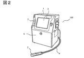
図2は、実施例1にかかる補給容器を搭載するインクジェット記録装置を示す全体図である。   FIG. 2 is an overall view showing the ink jet recording apparatus on which the supply container according to the first embodiment is mounted.

インクジェット記録装置100には、外部に操作表示部3が備えられた本体1とインク吐出ヘッド2が備えられており、本体1とインク吐出ヘッド2は導管4で接続されている。また本体1には状態表示灯5が備えられており、インクジェット記録装置100の運転状態、例えば電源通電状態、印字可能状態、警報状態、異常状態などを点灯により表示可能である。インクジェット記録装置100にはメンテナンス扉6が備えられ、ユーザーはメンテナンス扉6を開いてインクの補給などのメンテナンスを行うことができる。   The ink jet recording apparatus 100 includes a main body 1 provided with an operation display unit 3 outside and an ink discharge head 2, and the main body 1 and the ink discharge head 2 are connected by a conduit 4. Further, the main body 1 is provided with a status indicator lamp 5 and can display the operation state of the ink jet recording apparatus 100, for example, a power supply energized state, a printable state, an alarm state, an abnormal state, and the like by lighting. The inkjet recording apparatus 100 is provided with a maintenance door 6, and the user can perform maintenance such as ink replenishment by opening the maintenance door 6.

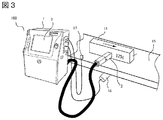
図3は、実施例1にかかる補給容器が搭載されるインクジェット記録装置の実使用状態の一例を示す図である。   FIG. 3 is a diagram illustrating an example of an actual use state of the ink jet recording apparatus on which the supply container according to the first embodiment is mounted.

インクジェット記録装置100は、例えば、食品や飲料などが生産される工場内の生産ラインに据え付けられ、本体1は使用者が操作できる位置に設置され、インク吐出ヘッド2はベルトコンベア15などの生産ライン上を搬送される印字対象物13に近接できる位置に設置される。   The ink jet recording apparatus 100 is installed on a production line in a factory where food, beverages, and the like are produced, for example, the main body 1 is installed at a position where the user can operate, and the ink discharge head 2 is a production line such as a belt conveyor 15. It is installed at a position where it can come close to the printing object 13 conveyed on the top.

ベルトコンベア15などの生産ライン上には搬送速度に係わらず同じ幅で印字するために、搬送速度に応じた信号をインクジェット記録装置100に出力するエンコーダ16や、印字対象物13を検出してインクジェット記録装置100に印字を指示する信号を出力する印字センサ17が設置されていて、それぞれは本体1内の図示しない制御部200に接続されている。   In order to print on the production line such as the belt conveyor 15 with the same width regardless of the transport speed, the encoder 16 that outputs a signal corresponding to the transport speed to the ink jet recording apparatus 100 or the print object 13 is detected and the ink jet is detected. Print sensors 17 that output signals for instructing printing to the recording apparatus 100 are installed, and each is connected to a control unit 200 (not shown) in the main body 1.

エンコーダ16や印字センサ17からの信号に応じて制御部200がノズル8から吐出されるインク粒子10への帯電量や帯電タイミングを制御し、印字対象物13がインク吐出ヘッド2近傍を通過する間に帯電、偏向されたインク粒子10を印字対象物13へ付着させて印字を行うようになっている。   While the control unit 200 controls the charge amount and timing of the ink particles 10 ejected from the nozzles 8 in accordance with signals from the encoder 16 and the print sensor 17, while the print target 13 passes near the ink ejection head 2. The ink particles 10 that have been charged and deflected are attached to the print object 13 for printing.

図4は、実施例1にかかる補給容器が搭載されるインクジェット記録装置の制御構成を示す図である。   FIG. 4 is a diagram illustrating a control configuration of the ink jet recording apparatus on which the supply container according to the first embodiment is mounted.

制御構成としては、演算機能を有しインクジェット記録装置全体を制御するMPU101が、バス120によりMPUが動作するために必要なプログラムやデータを記憶するROM102、プログラム実行中に必要なデータを一時的に記憶するRAM103、印字内容や設定値などを入力する入力装置104、入力装置104で入力された内容や状態などを表示する表示装置105、インク吐出ヘッド2内のノズル151に取り付けられた励振素子152に与える励振電圧を発生させる励振電圧発生回路111、ノズル151から吐出されたインク粒子161に電荷を与えるための帯電電極153に与える帯電電圧を発生させる帯電電圧発生回路112、帯電したインク粒子161を印字内容に合わせて偏向するための偏向電極154に与える偏向電圧を発生させる偏向電圧発生回路113、インクや溶剤の流れの開閉を行う電磁弁の制御を行う電磁弁制御回路114、インクに圧力を与えるポンプの制御を行うポンプ制御回路115、インク容器201、インクサブ容器202、溶剤サブ容器203の液面を検出する液面検出回路116に接続されている。   As a control configuration, the MPU 101 that has an arithmetic function and controls the entire inkjet recording apparatus, the ROM 102 that stores programs and data necessary for the MPU to operate by the bus 120, and the data necessary during program execution are temporarily stored. RAM 103 for storage, input device 104 for inputting print contents and setting values, display device 105 for displaying the content and state inputted by the input device 104, and excitation element 152 attached to the nozzle 151 in the ink ejection head 2 An excitation voltage generation circuit 111 for generating an excitation voltage to be applied to the charging electrode, a charging voltage generation circuit 112 for generating a charging voltage to be applied to the charging electrode 153 for applying an electric charge to the ink particles 161 ejected from the nozzles 151, and a charged ink particle 161. Provided to the deflection electrode 154 for deflecting according to the printing contents A deflection voltage generation circuit 113 that generates a deflection voltage, an electromagnetic valve control circuit 114 that controls an electromagnetic valve that opens and closes the flow of ink and solvent, a pump control circuit 115 that controls a pump that applies pressure to ink, and an ink container 201 The liquid level detection circuit 116 detects the liquid level of the ink sub container 202 and the solvent sub container 203.

インク容器、インクサブ容器、溶剤サブ容器については後で説明する。   The ink container, ink sub container, and solvent sub container will be described later.

図5は、実施例1にかかる補給容器が搭載されるインクジェット記録装置のインク循環システムの系統図である。   FIG. 5 is a system diagram of an ink circulation system of the ink jet recording apparatus on which the supply container according to the first embodiment is mounted.

本体1内には、ノズル151へ供給するインクを貯留し、またノズルへ供給したインクのうち印字に使用されなかったインクを回収し再び貯留するインク容器201、インク容器201に補給するインクを貯留するインクサブ容器202、インクの希釈や経路の洗浄に使用する溶剤を貯留する溶剤サブ容器203、インクまたは溶剤に圧力を与えるポンプ211から214、インクや溶剤の経路を開閉する電磁弁221から228、インク中のごみを捕集するフィルター231、ポンプ211により高められたインクの圧力を低減し必要な圧力に調整する減圧弁232、インクの圧力を測定する圧力計233、インクの粘度を測定する粘度計234が備えられている。インク吐出ヘッド2には、減圧弁232のOUT側、電磁弁228のOUT側へそれぞれ通じる2つのINポートとノズル151のIN側へ通じるOUTポートを持ち、2つのインポートのうちどちらかを閉じどちらかを開きOUTポートと連通させる三方電磁弁229、ノズルから吐出されたインクのうち印字に使用されないインクを捕らえるガター241が備えられている。   In the main body 1, ink to be supplied to the nozzle 151 is stored, ink among the ink supplied to the nozzle that has not been used for printing is collected and stored again, and ink to be supplied to the ink container 201 is stored. An ink sub-container 202, a solvent sub-container 203 that stores a solvent used for ink dilution and path cleaning, pumps 211 to 214 that apply pressure to the ink or the solvent, electromagnetic valves 221 to 228 that open and close the ink or solvent path, A filter 231 that collects dust in the ink, a pressure reducing valve 232 that reduces the pressure of the ink raised by the pump 211 and adjusts it to a required pressure, a pressure gauge 233 that measures the pressure of the ink, and a viscosity that measures the viscosity of the ink A total of 234 is provided. The ink discharge head 2 has two IN ports that respectively lead to the OUT side of the pressure reducing valve 232 and the OUT side of the solenoid valve 228, and an OUT port that leads to the IN side of the nozzle 151. A three-way solenoid valve 229 that opens and communicates with the OUT port, and a gutter 241 that catches ink that is not used for printing out of ink ejected from the nozzles are provided.

インクサブ容器202にはインク補給容器301が、溶剤サブ容器203には溶剤補給容器302がそれぞれ接続されている。インクサブ容器202および溶剤サブ容器203の内部のインクはそれぞれポンプ211、ポンプ214によって吸引、圧送され、インクや溶剤の経路を経てインク容器201に補給される。図は省略するが、インク容器201に接続されているポンプ212、ポンプ213、粘度計234とつながる経路をインクサブ容器202につなぎ、インク容器201から電磁弁222、および本体1の外部につながる経路を廃止して、インク容器201とインクサブ容器202を一体化とすることもできる。   An ink supply container 301 is connected to the ink sub container 202, and a solvent supply container 302 is connected to the solvent sub container 203. The ink in the ink sub-container 202 and the solvent sub-container 203 is sucked and pumped by the pump 211 and the pump 214, respectively, and replenished to the ink container 201 through the ink and solvent paths. Although illustration is omitted, a path connected to the pump 212, the pump 213, and the viscometer 234 connected to the ink container 201 is connected to the ink sub container 202, and a path connected from the ink container 201 to the electromagnetic valve 222 and the outside of the main body 1 is connected. The ink container 201 and the ink sub-container 202 may be integrated as a unit.

図7は、実施例1にかかる補給容器が搭載されるインクジェット記録装置のインク循環エリアの概観図である。   FIG. 7 is an overview of an ink circulation area of the ink jet recording apparatus in which the replenishing container according to the first embodiment is mounted.

インク循環エリア251はメンテナンス扉6を開くことでアクセスが可能である。インク循環エリア251には、ポンプ211から214や電磁弁221から228をユニット化したインク循環ユニット261やインクサブ容器202、溶剤サブ容器203が備えられており、それらの図示は省略するが、ねじなどにより固定されている。前述したように、インクサブ容器202にはインク補給容器301が、溶剤サブ容器203には溶剤補給容器302がそれぞれ接続されており、これらのインク補給容器301、溶剤補給容器302はユーザーにより着脱、交換が可能である。   The ink circulation area 251 can be accessed by opening the maintenance door 6. The ink circulation area 251 includes an ink circulation unit 261 in which pumps 211 to 214 and electromagnetic valves 221 to 228 are unitized, an ink sub-container 202, and a solvent sub-container 203. It is fixed by. As described above, the ink supply container 301 is connected to the ink sub-container 202, and the solvent supply container 302 is connected to the solvent sub-container 203, and these ink supply container 301 and solvent supply container 302 are attached, detached, and replaced by the user. Is possible.

図13は、実施例1にかかる補給容器が搭載されるインクジェット記録装置のインクサブ容器の一例を示す図である。   FIG. 13 is a diagram illustrating an example of the ink sub-container of the ink jet recording apparatus in which the supply container according to the first embodiment is mounted.

インクサブ容器の貯蔵部材501は貯蔵部511、補給口512、センサ口513を有し、補給口512にはアダプタ502がねじ503で固定されている。補給口512とアダプタ502の間にはゴム製のシール部材504が備えられ当該部分のシール性を確保している。貯蔵部材501の材質としては、ポリプロピレン樹脂や高密度ポリエチレン樹脂などが用いられる。   The ink sub-container storage member 501 includes a storage unit 511, a supply port 512, and a sensor port 513, and an adapter 502 is fixed to the supply port 512 with a screw 503. A rubber seal member 504 is provided between the replenishment port 512 and the adapter 502 to ensure the sealability of the portion. As a material of the storage member 501, a polypropylene resin, a high density polyethylene resin, or the like is used.

アダプタ502はインク補給容器301と接続するものであり、接続状態については後で説明する。アダプタ502には、その上部が鋭角形状532を形成する円筒部531と外壁部533が備えられる。アダプタ502の材質としては、ポリプロピレン樹脂やポリブチレンテレフタレート樹脂などが用いられる。   The adapter 502 is connected to the ink supply container 301, and the connection state will be described later. The adapter 502 includes a cylindrical portion 531 and an outer wall portion 533 whose upper portion forms an acute-angle shape 532. As a material of the adapter 502, polypropylene resin, polybutylene terephthalate resin, or the like is used.

貯蔵部材501のセンサ口513には、液面センサ505、吸引パイプ506、大気開放パイプ507が取り付けられたブロック508が蓋509のねじ嵌合により固定されている。吸引パイプ506の先端に吸引口522があり、この部分からインクサブ容器内の液は吸引され、経路の先へと運ばれる。   A block 508 to which a liquid level sensor 505, a suction pipe 506, and an air release pipe 507 are attached is fixed to the sensor port 513 of the storage member 501 by screwing a lid 509. There is a suction port 522 at the tip of the suction pipe 506, and the liquid in the ink sub-container is sucked from this portion and carried to the end of the path.

液面センサ505は、2本の金属棒から成り、導電性を有するインクの液面が2本の金属棒に触れる位置ではその2本が導通し、インク液面が2本の金属棒に触れない位置ではその2本は導通せず、この原理によりある1点の検出レベル521において液面が到達しているか否かを検出可能である。ここで2本の金属棒の上部には、図は省略するが導線が嵌合された端子などがねじどめなどにより固定され導線は液面検出回路116へとつながる。液面センサ505の金属棒の数を増やし複数の検出レベルをもつこともできる。   The liquid level sensor 505 is composed of two metal rods. When the liquid level of the conductive ink touches the two metal rods, the two are conducted, and the ink level touches the two metal rods. The two lines do not conduct at a position where no liquid exists, and it is possible to detect whether or not the liquid level has reached at a certain detection level 521 by this principle. Here, although not shown in the drawing, a terminal fitted with a conducting wire is fixed to the upper part of the two metal rods by screwing or the like, and the conducting wire is connected to the liquid level detection circuit 116. The number of metal bars of the liquid level sensor 505 can be increased to have a plurality of detection levels.

図6は、実施例1にかかる補給容器が搭載されるインクジェット記録装置においてインクサブ容器の液面制御フローの一例を示す図である。   FIG. 6 is a diagram illustrating an example of the liquid level control flow of the ink sub-container in the ink jet recording apparatus in which the replenishing container according to the first embodiment is mounted.

ステップ401において、インクサブ容器202に設けられた液面センサ505が検出レベル521において液面を検出しているかどうか確認する。   In step 401, it is confirmed whether the liquid level sensor 505 provided in the ink sub-container 202 has detected the liquid level at the detection level 521.

液面を検出していない場合、インクサブ容器内のインクが少なくなっていることを意味し、ステップ402においてに警報を表示する。またこのときインクサブ容器に接続されたインク補給容器は、その内部に貯留されていたインクをほとんど全てインクサブ容器内へ排出し、空の状態である。図13においてはインク補給容器の図は省略している。インク補給容器とインクサブ容器との接続状態の一例についてはあとで説明する。ステップ402における警報表示の例としては、状態表示灯5の警報ランプを点灯し、操作表示部3に警報マークおよびインク補給容器を規定時間T以内に新しいものに交換する必要がある内容のメッセージを表示する。通常、警報が解除されるまでの間は、前記警報ランプと警報マークは常時表示し、メッセージについてはユーザーが操作により消去可能である。警報が表示されたとしてもインクジェット記録装置100は通常通り印字や操作などを実行可能である。   If the liquid level is not detected, it means that the ink in the ink sub-container is low, and an alarm is displayed in step 402. At this time, the ink supply container connected to the ink sub-container discharges almost all the ink stored in the ink sub-container into the ink sub-container and is empty. In FIG. 13, the illustration of the ink supply container is omitted. An example of the connection state between the ink supply container and the ink sub-container will be described later. As an example of the alarm display in step 402, the alarm lamp of the status indicator lamp 5 is turned on, and a message indicating that it is necessary to replace the alarm mark and the ink supply container with a new one within the specified time T on the operation display unit 3. indicate. Usually, the alarm lamp and the alarm mark are always displayed until the alarm is released, and the message can be erased by the operation by the user. Even if an alarm is displayed, the inkjet recording apparatus 100 can execute printing, operation, and the like as usual.

ステップ401において液面を検出している場合は、インクサブ容器内のインクは十分残っているため警報の表示は行わない。   If the liquid level is detected in step 401, no alarm is displayed because sufficient ink remains in the ink sub-container.

ステップ403では液面を非検出となってから規定時間Tが経過したかどうかを確認する。規定時間Tが経過した場合、使用環境や印字頻度によってはインクサブ容器内のインクがほとんど残っていないことが想定され、仮にその後も印字を継続するとインク経路にインクの代わりに空気を吸い込み、ポンプ性能を低下させたり、ノズルから空気を噴出させることにより、印字乱れが発生する恐れがあるため、ステップ406にて異常状態を表示し、インクジェット記録装置100の運転を停止させる。   In step 403, it is confirmed whether the specified time T has elapsed since the liquid level was not detected. When the specified time T has elapsed, depending on the usage environment and printing frequency, it is assumed that almost no ink remains in the ink sub-container. If printing continues after that, air is sucked into the ink path instead of ink, and the pump performance In this case, an abnormal state is displayed in step 406, and the operation of the ink jet recording apparatus 100 is stopped.

規定時間Tが経過していない場合は、ステップ404において液面をいまだ検出していないかどうか確認する。ステップ404においても液面を検出していない場合はステップ403に戻る。   If the specified time T has not elapsed, it is confirmed in step 404 whether the liquid level has not yet been detected. If the liquid level is not detected in step 404, the process returns to step 403.

インク補給容器が新しいものに交換されると、インク補給容器内のインクはインクサブ容器内に排出され、インクサブ容器内の液面が上昇し液面センサが検出レベル521において液面を検出し、ステップ405に移行する。   When the ink supply container is replaced with a new one, the ink in the ink supply container is discharged into the ink sub-container, the liquid level in the ink sub-container rises, and the liquid level sensor detects the liquid level at the detection level 521. 405.

ステップ405ではステップ402において表示した警報を解除する。図6に示す液面制御フローは溶剤サブ容器についても同様であり、溶剤サブ容器の液面センサが液面を検出しない場合の、ステップ402における警報表示の例としては、溶剤補給容器を規定時間T以内に新しいものに交換する必要がある内容のメッセージを表示する。   In step 405, the alarm displayed in step 402 is canceled. The liquid level control flow shown in FIG. 6 is the same for the solvent sub-container. As an example of the alarm display in step 402 when the liquid level sensor of the solvent sub-container does not detect the liquid level, the solvent replenishment container is set to the specified time. A message indicating that it is necessary to exchange for a new one within T is displayed.

検出レベル521は吸引パイプ506の吸引口522より上方にある一定距離隔てた位置に設けられる。これにより、インクジェット記録装置100の運転中に印字などによりインクサブ容器202内のインクが減少し、液面が検出レベル521より低下し警報が発せられてから、吸引不可能になるまでに一定時間の間隔が開き、ユーザーが警報の発生を認知しインク補給容器301を交換するまでの猶予時間を設けることができる。   The detection level 521 is provided at a position spaced apart from the suction port 522 of the suction pipe 506 by a certain distance. As a result, the ink in the ink sub-container 202 is reduced due to printing or the like during the operation of the ink jet recording apparatus 100, the liquid level falls below the detection level 521, an alarm is issued, and a certain period of time is passed from when the suction becomes impossible. The interval is increased, and a grace period until the user recognizes the occurrence of the alarm and replaces the ink supply container 301 can be provided.

吸引パイプ506の上部にはフッ素樹脂チューブが圧入により接続されインク循環ユニット261へ接続され、その経路は電磁弁221を介してポンプ211へとつながる。大気開放パイプ507の上部にはフッ素樹脂チューブが圧入により接続されその経路はインクジェット記録装置100の外部の大気へとつながり、インクサブ容器内のインクが吸引パイプ506より吸引されると大気開放パイプから空気がインクサブ容器内へ流入する。溶剤サブ容器203は、内部に貯蔵する溶剤が通常導電性を有さないためインクサブ容器とは異なる方式の液面センサを用いるが、図6に示す液面制御フローは同様であり、液面センサを除けば図12に示す構造は同様である。溶剤サブ容器の液面センサとしては、フロートセンサなどが用いられる。またフロートセンサをインクサブ容器202に用いてもよい。溶剤サブ容器の構造図については省略する。   A fluororesin tube is connected to the upper portion of the suction pipe 506 by press-fitting and connected to the ink circulation unit 261, and the path is connected to the pump 211 via the electromagnetic valve 221. A fluororesin tube is connected to the upper part of the atmosphere release pipe 507 by press-fitting, and the path is connected to the atmosphere outside the inkjet recording apparatus 100. When the ink in the ink sub container is sucked from the suction pipe 506, the air is released from the atmosphere release pipe. Flows into the ink sub-container. The solvent sub-container 203 uses a liquid level sensor of a different type from that of the ink sub-container because the solvent stored therein usually does not have conductivity, but the liquid level control flow shown in FIG. Except for, the structure shown in FIG. 12 is the same. A float sensor or the like is used as the liquid level sensor of the solvent sub-container. A float sensor may be used for the ink sub container 202. A structural diagram of the solvent sub-container is omitted.

図1は、実施例1にかかるインク補給容器の全体構造を示す断面図である。   FIG. 1 is a cross-sectional view illustrating the overall structure of the ink supply container according to the first embodiment.

なお、インク補給容器301及び溶剤補給容器302は同様の構造であり、以下ではインク補給容器についてのみ説明し、溶剤補給容器についての説明は省略する。   The ink supply container 301 and the solvent supply container 302 have the same structure, and only the ink supply container will be described below, and the description of the solvent supply container will be omitted.

図1(a)は全体構造を、図1(b)はインク補給容器301の先端部を拡大して示したものである。図1(a)に示すように、インク補給容器301は、貯蔵部材311と栓部材312と第1の蓋部材313とシール部材314と液体吸収材315と第2の蓋部材316を備えている。
インク補給容器301の材質の例としては、貯蔵部材311、第1の蓋部材313、第2の蓋部材316には、高密度ポリエチレン樹脂(HDPE)や低密度ポリエチレン樹脂(LDPE)や直鎖状低密度ポリエチレン樹脂(LLDPE)やポリプロピレン樹脂(PP)が用いられ、栓部材312には、低密度ポリエチレン樹脂(LDPE)や直鎖状低密度ポリエチレン樹脂(LLDPE)が用いられる。
FIG. 1A shows the overall structure, and FIG. 1B shows an enlarged front end portion of the ink supply container 301. As shown in FIG. 1A, the ink supply container 301 includes a storage member 311, a plug member 312, a first lid member 313, a seal member 314, a liquid absorbent material 315, and a second lid member 316. .
As an example of the material of the ink supply container 301, the storage member 311, the first lid member 313, and the second lid member 316 include a high-density polyethylene resin (HDPE), a low-density polyethylene resin (LDPE), or a linear shape. Low density polyethylene resin (LLDPE) or polypropylene resin (PP) is used, and the plug member 312 is made of low density polyethylene resin (LDPE) or linear low density polyethylene resin (LLDPE).

また、シール部材314には弾性体であるブチルゴムあるいはエチレンプロピレンゴムが用いられ、液体吸収材315には連続気泡のポリオレフィン系発泡体あるいはポリオレフィン系不織布が用いられる。なお、上記材質は本実施例における好適なものであり、他のものを用いてもよい。   The sealing member 314 is made of elastic butyl rubber or ethylene propylene rubber, and the liquid absorbent material 315 is made of open-cell polyolefin foam or polyolefin nonwoven. In addition, the said material is a suitable thing in a present Example, You may use another thing.

インク補給容器301の詳細構造を説明すれば、貯蔵部材311は直方体形状の貯蔵室321を有し、貯蔵室321の一端部から延出した壁面の先端部322は円筒形状をしており、その端面は開口している。先端部322の外周縁にはねじが形成されている。貯蔵室321は直方体形状以外に円筒形状などでもよい。先端部322と貯蔵室321をつなぐ壁面は傾斜しており、インク補給容器301の開口を下に向けて内容液を排出する際に内部に液が残りにくくしている。
先端部322の開口部には、先端部322の内部に挿入されるように栓部材312が取り付けられている。栓部材312は円筒部331、鍔部332、底部333を備え、円筒部331の端部に鍔部332が形成され、他方の端部には底部333が形成されている。鍔部332が貯蔵部材311の先端部322の開口端部に掛止されて栓部材312が取り付けられ、その接触部は円周に沿って1周連続的に密接しており、当該部のシール性を確保している。また、円筒部331の外側面は貯蔵部材の先端部322の内側面に対し1周連続的に密接し、当該部のシール性を確保し、以上のように二重シール構造とすることで、信頼性の高い液漏れ防止構造となっている。
The detailed structure of the ink supply container 301 will be described. The storage member 311 has a rectangular parallelepiped storage chamber 321, and the front end 322 of the wall surface extending from one end of the storage chamber 321 has a cylindrical shape. The end face is open. A screw is formed on the outer peripheral edge of the tip portion 322. The storage chamber 321 may have a cylindrical shape in addition to the rectangular parallelepiped shape. The wall surface connecting the front end 322 and the storage chamber 321 is inclined so that the liquid does not easily remain inside when the content liquid is discharged with the opening of the ink supply container 301 facing downward.
A plug member 312 is attached to the opening of the tip 322 so as to be inserted into the tip 322. The plug member 312 includes a cylindrical portion 331, a flange portion 332, and a bottom portion 333. A flange portion 332 is formed at an end portion of the cylindrical portion 331, and a bottom portion 333 is formed at the other end portion. The hook portion 332 is hooked on the opening end portion of the tip end portion 322 of the storage member 311 and the plug member 312 is attached, and the contact portion is in close contact with one circumference continuously along the circumference. The sex is secured. In addition, the outer side surface of the cylindrical portion 331 is in close contact with the inner side surface of the tip portion 322 of the storage member for one round continuously, ensuring the sealing performance of the portion, and having a double seal structure as described above. It has a highly reliable liquid leakage prevention structure.

栓部材312の底部333には環状にその周囲より肉厚の小さい薄肉部341を有している。本実施例では、インク補給容器301と本体機側のサブインク容器202とを接続する際に、サブインク容器202に設けられた接続部突起によって、インク補給容器301の栓部材312の底部333の一部が突き破られる構成となっており、この薄肉部341はインクを補給する際に小さい操作力で突き破るためのものであり、薄肉部の肉厚は0.2から0.5mm程度が望ましい。   The bottom portion 333 of the plug member 312 has an annular thin portion 341 having a thickness smaller than that of the periphery thereof. In this embodiment, when the ink supply container 301 and the sub ink container 202 on the main body side are connected, a part of the bottom 333 of the plug member 312 of the ink supply container 301 is formed by the connection protrusion provided on the sub ink container 202. This thin portion 341 is for breaking through with a small operating force when replenishing ink, and the thickness of the thin portion is preferably about 0.2 to 0.5 mm.

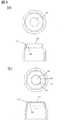
図8は、実施例1にかかる補給容器の栓部材の一例を示す図である。   FIG. 8 is a diagram illustrating an example of a plug member of the supply container according to the first embodiment.

図8(a)は環状に連続的に薄肉部341が形成され、図8(b)は環状に断続的に薄肉部341が形成されている。   In FIG. 8A, the thin portion 341 is continuously formed in an annular shape, and in FIG. 8B, the thin portion 341 is formed intermittently in an annular shape.

続いて、図1(b)で示すように、第1の蓋部材313は円筒部351、底部352を有し、円筒部351の内側面にはねじが形成され、貯蔵部材311の先端部322外側に形成されたねじと係合し固定されている。   Subsequently, as shown in FIG. 1B, the first lid member 313 has a cylindrical portion 351 and a bottom portion 352, a screw is formed on the inner side surface of the cylindrical portion 351, and the distal end portion 322 of the storage member 311. It is engaged and fixed with a screw formed on the outside.

第1の蓋部材の底部352には貫通穴353を有しており、第1の蓋部材の貫通穴353は栓部材312の環状薄肉部341と同心状に配置されている。   The bottom portion 352 of the first lid member has a through hole 353, and the through hole 353 of the first lid member is disposed concentrically with the annular thin portion 341 of the plug member 312.

図9は、実施例1にかかる補給容器の第1の蓋部材の一例を示す図である。   FIG. 9 is a diagram illustrating an example of the first lid member of the supply container according to the first embodiment.

図9(a)は貫通穴353が円形に形成され、図9(b)は貫通穴353が円354に沿った部分355とその周囲に凹である部分356で形成されている。   9A, the through-hole 353 is formed in a circular shape, and in FIG. 9B, the through-hole 353 is formed by a portion 355 along the circle 354 and a portion 356 that is concave in the periphery thereof.

さらに、図1(b)で示すように、栓部材312の底面部333には、底面部333の周縁に沿ってシール部材314が設けられている。   Further, as shown in FIG. 1B, a seal member 314 is provided on the bottom surface portion 333 of the plug member 312 along the periphery of the bottom surface portion 333.

シール部材314は、円筒部366、鍔部367、底部368を備え、円筒部366の端部に鍔部367が形成されている。円筒部366の他方の端部には底部368が形成され、円筒の内径側の穴361を塞いでいる。円筒部366の内側面には2個の環状突起362、363が備えられ、環状突起362、363は円筒部366と同心状に形成されており、また第1の蓋部材313の貫通穴353と同心状に配置されている。円筒部366は底部368に対し、貯蔵部材311のより外側に配置される。   The seal member 314 includes a cylindrical portion 366, a flange portion 367, and a bottom portion 368, and a flange portion 367 is formed at the end of the cylindrical portion 366. A bottom portion 368 is formed at the other end of the cylindrical portion 366 and closes a hole 361 on the inner diameter side of the cylinder. Two annular projections 362 and 363 are provided on the inner surface of the cylindrical portion 366, and the annular projections 362 and 363 are formed concentrically with the cylindrical portion 366, and the through hole 353 of the first lid member 313 is formed. They are arranged concentrically. The cylindrical portion 366 is disposed on the outer side of the storage member 311 with respect to the bottom portion 368.

また、環状突起362、363は底部368に対し、貯蔵部材311のより外側に配置される。ここで、少なくとも1つの環状突起が底部368に対し、貯蔵部材311のより外側に配置されるものでもよい。また底部368は円筒部366の端部でなく、円筒部366の中間位置に設けられてもよい。   Further, the annular protrusions 362 and 363 are disposed on the outer side of the storage member 311 with respect to the bottom portion 368. Here, at least one annular protrusion may be disposed on the outer side of the storage member 311 with respect to the bottom portion 368. Further, the bottom portion 368 may be provided at an intermediate position of the cylindrical portion 366 instead of the end portion of the cylindrical portion 366.

鍔部367は、液吸収材315を鍔部367と接触するように配置するときに、接触面積を広く設け、液吸収材315をより安定して配置するためのものである。液吸収部材315は鍔部367に接着剤や両面粘着テープによって接着され固定される。液吸収材315はインク補給容器301の中で多少の配置のずれがあってもインク漏れに影響がないため、接着せずに配置するだけでもよい。その際は液吸収材315の円筒形状の両端面をそれぞれ、シール部材314、第1の蓋部材と接触または近接させ、円筒形状の外径を第1の蓋部材と接触または近接させ、移動可能量を制限するのがよい。シール部材314の鍔部367はなくてもよい。   The flange portion 367 is provided to provide a wide contact area when the liquid absorbent material 315 is disposed so as to be in contact with the flange portion 367 and to arrange the liquid absorbent material 315 more stably. The liquid absorbing member 315 is bonded and fixed to the flange portion 367 with an adhesive or a double-sided adhesive tape. Since the liquid absorbing material 315 does not affect ink leakage even if there is a slight dislocation in the ink supply container 301, it may be disposed without adhering. At that time, both end surfaces of the cylindrical shape of the liquid absorbing material 315 are brought into contact with or close to the seal member 314 and the first lid member, respectively, and the cylindrical outer diameter is brought into contact with or close to the first lid member to be movable. The amount should be limited. The flange 367 of the seal member 314 may not be provided.

シール部材314の内側面の環状突起は、例えばある円筒状部材の外側面が環状突起と円周に沿って1周連続的に密接しシール部材を圧縮することで当該部のシール性を確保するためのものである。更にその円筒状部材の外側面がシール部材314の円筒部366の内面のうち、環状突起部には密接しシール部材を圧縮し、それ以外の部分を圧縮しない寸法関係にすることで、シール部材の圧縮反力を必要最低限にし、その円筒状部材がシール部材314を圧縮したまま軸方向に移動するときにシール部材の圧縮反力により生じる摩擦力を軽減する効果がある。なお、環状突起の数は2個に限定されるものではなく1個あるいは3個以上でもよく、突起を有していなくてもシール性が確保されていればよい。ここで述べた円筒状部材は、インクサブ容器202のアダプタ502の円筒部531が該当する。   The annular protrusion on the inner surface of the sealing member 314 ensures the sealing performance of the part by compressing the sealing member, for example, by bringing the outer surface of a certain cylindrical member into close contact with the annular protrusion continuously around the circumference. Is for. Further, the outer surface of the cylindrical member is in close contact with the annular projection portion of the inner surface of the cylindrical portion 366 of the seal member 314, and the seal member is compressed, and the other portions are not dimensionally compressed. This is effective in reducing the frictional force generated by the compression reaction force of the seal member when the cylindrical member moves in the axial direction while compressing the seal member 314. Note that the number of the annular protrusions is not limited to two, but may be one or three or more as long as the sealing property is ensured even if the protrusions are not provided. The cylindrical member described here corresponds to the cylindrical portion 531 of the adapter 502 of the ink sub container 202.

シール部材314の外側面には2個の環状突起364、365が形成されており、環状突起364、365は栓部材の円筒部331の内側面と円周に沿って1周連続的に密接しシール性を確保している。ここで外側面の環状突起の数は2個に限定されるものではなく1個あるいは3個以上でもよく、また突起がなくシール部材の外側面が栓部材の円筒部の内側面と円周に沿って連続的に密接する形でもよい。また、インク補給容器301がインクサブ容器202のアダプタ502と非接続のときには、シール部材の外側面の環状突起364、365と栓部材の円筒部331の内側面との間にシール性は不要であり、当該部分は密接していなくてもよく、インク補給容器301がアダプタ502と接続されているときに、円筒部531との接触によってシール部材314が変形して栓部材の円筒部の内側面と密接する形態でもよい。    Two annular protrusions 364 and 365 are formed on the outer surface of the seal member 314. The annular protrusions 364 and 365 are in close contact with the inner surface of the cylindrical portion 331 of the plug member continuously around the circumference. Sealing performance is secured. Here, the number of the annular projections on the outer surface is not limited to two, but may be one or more, and there is no projection and the outer surface of the seal member is on the inner surface and the circumference of the cylindrical portion of the plug member. It may be in the form of continuous intimate contact. Further, when the ink supply container 301 is not connected to the adapter 502 of the ink sub-container 202, no sealing property is required between the annular protrusions 364 and 365 on the outer surface of the seal member and the inner surface of the cylindrical portion 331 of the plug member. The portion does not have to be in close contact, and when the ink supply container 301 is connected to the adapter 502, the seal member 314 is deformed by contact with the cylindrical portion 531, and the inner surface of the cylindrical portion of the plug member Close form may be sufficient.

シール部材314の内側面の環状突起362、363の内径372、373は蓋部材の貫通穴353の内径371より小さくなっている。これにより蓋部材の貫通穴353の内径より小さいがほとんど同一寸法の外径であって、環状突起の内径372、373より大きい外径である本体側インク補給容器のアダプタ502の円筒部531が蓋部材の貫通穴353より同軸状に挿入されたときに、シール部材314の内側面の環状突起362、363と前記円筒部531の外側面が円周上に1周連続的に密接し、当該部分のシール性を確保することができる。   The inner diameters 372 and 373 of the annular projections 362 and 363 on the inner surface of the seal member 314 are smaller than the inner diameter 371 of the through hole 353 of the lid member. As a result, the cylindrical portion 531 of the adapter 502 of the main body side ink supply container which is smaller than the inner diameter of the through-hole 353 of the lid member but has almost the same outer diameter and larger than the inner diameters 372 and 373 of the annular protrusions is covered. When inserted coaxially through the through-hole 353 of the member, the annular projections 362 and 363 on the inner surface of the seal member 314 and the outer surface of the cylindrical portion 531 are in close contact with each other on the circumference one by one, The sealing property can be ensured.

図14は、実施例1にかかる補給容器のシール部材の製造方法の一例を示す図である。   FIG. 14 is a diagram illustrating an example of the manufacturing method of the sealing member of the supply container according to the first embodiment.

図14(a)はコンプレッション成形法において、上部金型451と下部金型452によってゴム材料453が成形される様子を示している。金型にはゴムの所望形状が複数設けられており、それにより生産性を高め製造コストを低減している。ゴムは所望形状部461とシート部462が一体につながった状態に成形され、この金型から取り出される。   FIG. 14A shows how the rubber material 453 is molded by the upper mold 451 and the lower mold 452 in the compression molding method. The mold is provided with a plurality of desired shapes of rubber, thereby increasing productivity and reducing manufacturing costs. The rubber is molded in a state where the desired shape portion 461 and the sheet portion 462 are integrally connected, and is taken out from the mold.

図14(b)は、前述の状態で金型から取出されたゴムをポンチ471とダイ472によって所望形状部461をシート部462から切り離す様子を示している。ポンチ471は図中の矢印方向に移動し、シート部462をせん断加工により切り離す。   FIG. 14B shows how the desired shape portion 461 is separated from the sheet portion 462 by the punch 471 and the die 472 of the rubber taken out from the mold in the above-described state. The punch 471 moves in the direction of the arrow in the figure and separates the sheet portion 462 by shearing.

図14(c)は、せん断加工後のゴムの所望形状部461を示している。切断箇所480には、せん断加工におけるポンチ471とダイ472のクリアランスなどにより、微小なバリ481が残る。このバリ481はシール部材314にとって不要なものであり、またシール部材314が栓部材312に挿入・組み立てされる際などに部材同士の擦れ合いによりバリ481がシール部材314から切り離され、場合によってはそれがシール部に付着しシール性を阻害する恐れがある。そのため、通常せん断加工後のゴムに対し、バリの有無や程度を検査し、バリの大きさが許容値から外れて大きい場合はバリをカッターなどで除去するか、バリの大きい完成品は廃棄するなどの処置が取られる。   FIG. 14C shows the desired shape portion 461 of the rubber after the shearing process. A minute burr 481 remains at the cut location 480 due to the clearance between the punch 471 and the die 472 in the shearing process. The burr 481 is unnecessary for the seal member 314, and when the seal member 314 is inserted and assembled into the plug member 312, the burr 481 is separated from the seal member 314 due to friction between the members. It may adhere to the seal part and hinder the sealing performance. Therefore, usually the rubber after shearing is inspected for the presence and level of burrs. If the size of the burrs is larger than the allowable value, the burrs are removed with a cutter, or the finished product with large burrs is discarded. Such actions are taken.

図15は、従来のインク補給容器の一例を示す図である。
図15(a)はインク補給容器601の先端部を示す。インク補給容器601は、貯蔵部材602、栓部材603、第1の蓋部材604、シール部材605、液吸収材606、第2の蓋部材607で構成される。ここで貯蔵部材602の一部と第2の蓋部材607の図は省略されているが、前述のインク補給容器301と同様である。図15(b)はインク補給容器601のシール部材605を示している。
FIG. 15 is a diagram illustrating an example of a conventional ink supply container.
FIG. 15A shows the tip of the ink supply container 601. The ink supply container 601 includes a storage member 602, a plug member 603, a first lid member 604, a seal member 605, a liquid absorbing material 606, and a second lid member 607. Here, the illustration of a part of the storage member 602 and the second lid member 607 is omitted, but it is the same as the ink supply container 301 described above. FIG. 15B shows the seal member 605 of the ink supply container 601.

シール部材605は円筒部611と鍔部612を備えており、円筒部611の中央には貫通穴613を有する。シール部材605の製造方法の一例としては、図は省略するがシール部材314と同様の製造方法が用いられる。   The seal member 605 includes a cylindrical portion 611 and a flange portion 612, and has a through hole 613 at the center of the cylindrical portion 611. As an example of the manufacturing method of the seal member 605, a manufacturing method similar to that of the seal member 314 is used, although not shown.

まず、図14(a)と同様にゴム材料が成形されるが、このとき円筒内側の穴にはシート形状が円筒部のいずれかの端面、もしくは円筒部の中間位置に、穴をふさぐように一体的につながって成形される。その後図14(b)と同様にポンチとダイで所望形状がシートからせん断加工により切り離される。そのとき円筒中央のシート形状も切り離される。   First, a rubber material is molded in the same manner as in FIG. 14 (a). At this time, in the hole on the inner side of the cylinder, the sheet shape is blocked at one of the end faces of the cylindrical part or the intermediate position of the cylindrical part. Molded together. Thereafter, the desired shape is separated from the sheet by shearing with a punch and a die as in FIG. At that time, the sheet shape at the center of the cylinder is also cut off.

せん断加工後は、図14(c)のようなバリが円筒部周囲の切断部と円筒部内部の切断部に発生し、その後それらのバリの検査、除去などの作業が行われる。前述した本発明の一実施例であるシール部材314は、公知のシール部材605と比較し、その製造工程において円筒部内側のシートの切断、およびその部分に発生するバリの検査、除去などの作業が不要であり、製造コストを低減することができる。   After the shearing process, burrs as shown in FIG. 14C are generated at the cutting portion around the cylindrical portion and the cutting portion inside the cylindrical portion, and thereafter, such operations as inspection and removal of these burrs are performed. Compared with the known seal member 605, the seal member 314 according to the embodiment of the present invention described above is a process of cutting the sheet inside the cylindrical portion and inspecting and removing burrs generated in the portion in the manufacturing process. Is unnecessary, and the manufacturing cost can be reduced.

公知のシール部材605の製造方法において、前述した図14(a)と同様の成形時に、円筒中央部の金型を当接させて、円筒部内側にシート形状を成形せず、円筒部内側のシート切断作業を省略することは可能であるが、その際にも円筒部中央の金型当接部にも一部ゴム材料が入り込みバリが発生するため、当該部のバリの検査、除去などの作業は結局必要となる。
インク補給容器301の先端部は図10に示すような形態であってもよい。
In the known manufacturing method of the seal member 605, at the time of molding similar to that shown in FIG. 14A, the mold at the center of the cylinder is brought into contact, and the sheet shape is not molded inside the cylinder. It is possible to omit the sheet cutting operation, but at that time, part of the rubber material enters the mold contact part at the center of the cylindrical part, and burrs are generated. Work is eventually necessary.
The tip of the ink supply container 301 may have a form as shown in FIG.

図10は、実施例1にかかる補給容器の一例を示す図である。   FIG. 10 is a diagram illustrating an example of a supply container according to the first embodiment.

本例ではシール部材314は、円形断面部411と底部412で構成され、円形断面部を概円筒形状とみなすと概円筒形状の端部に円筒内側の穴を塞ぐように底部412が形成されている。ここで底部412は概円筒形状の端部でなく中間位置であってもよい。インク補給容器301において、シール部材の概円筒形状は底部412に対し、貯蔵部材311のより外側に配置される。シール部材の概円筒形状の内径は第1の蓋部材313の貫通穴353の内径より小さくなっている。このインク補給容器では液吸収材315はシール部材314と接着せず、接触させて配置される。   In this example, the seal member 314 includes a circular cross section 411 and a bottom 412. When the circular cross section is regarded as a substantially cylindrical shape, the bottom 412 is formed so as to close the hole inside the cylinder at the end of the substantially cylindrical shape. Yes. Here, the bottom portion 412 may be an intermediate position instead of the end portion of the substantially cylindrical shape. In the ink supply container 301, the substantially cylindrical shape of the seal member is disposed on the outer side of the storage member 311 with respect to the bottom 412. The inner diameter of the substantially cylindrical shape of the seal member is smaller than the inner diameter of the through hole 353 of the first lid member 313. In this ink supply container, the liquid absorbing material 315 is disposed in contact with the seal member 314 without being bonded.

インク補給容器301の先端部の構造は図12に示すようなものでもよい。   The structure of the tip of the ink supply container 301 may be as shown in FIG.

図12は、実施例1にかかるインク補給容器の一例を示す図である。   FIG. 12 is a diagram illustrating an example of the ink supply container according to the first embodiment.

図12で示すインク補給容器301は貯蔵部材311、栓部材421、シール部材314、液吸収材315、第1の蓋部材422と第2の蓋部材316で構成される。第2の蓋部材は図1で示すインク補給容器301のものと同様でありこの図では省略する。栓部材421は、前述の栓部材312と第1の蓋部材313の円筒部351が一体的に成形された形態である。また、第1の蓋部材422は、前述の第1の蓋部材313の底部352に該当する。栓部材421と第1の蓋部材422は、それぞれに設けられた凸部426、427の係り合いによって取り付けられる。栓部材421と第1の蓋部材422の材質の例としては、栓部材421には低密度ポリエチレン樹脂(LDPE)や直鎖状低密度ポリエチレン樹脂(LLDPE)、第1の蓋部材422には高密度ポリエチレン樹脂(HDPE)や低密度ポリエチレン樹脂(LDPE)やポリプロピレン樹脂(PP)が用いられる。   An ink supply container 301 shown in FIG. 12 includes a storage member 311, a plug member 421, a seal member 314, a liquid absorbing material 315, a first lid member 422 and a second lid member 316. The second lid member is the same as that of the ink supply container 301 shown in FIG. The plug member 421 has a form in which the aforementioned plug member 312 and the cylindrical portion 351 of the first lid member 313 are integrally formed. The first lid member 422 corresponds to the bottom portion 352 of the first lid member 313 described above. The plug member 421 and the first lid member 422 are attached by engagement of convex portions 426 and 427 provided on each. Examples of the material of the plug member 421 and the first lid member 422 include a low density polyethylene resin (LDPE) or a linear low density polyethylene resin (LLDPE) for the plug member 421, and a high value for the first lid member 422. A high density polyethylene resin (HDPE), a low density polyethylene resin (LDPE), or a polypropylene resin (PP) is used.

次に吸収剤315について説明する。吸収材315の材質の例として、前述のように連続気泡のポリオレフィン発泡体やポリオレフィン不織布が用いられる。いずれにしても吸収材315の外面から内部に連続的に隙間を有しており、その隙間部に液体を吸収することができる。 また、吸収材315は貫通穴381を有しており、吸収材の貫通穴381は蓋部材の貫通穴353と同心状に配置されている。吸収材315の固定方法としては、前述しておりここでは省略する。   Next, the absorbent 315 will be described. As an example of the material of the absorbent material 315, an open-cell polyolefin foam or a polyolefin nonwoven fabric is used as described above. In any case, a gap is continuously formed from the outer surface of the absorbent 315 to the inside, and the liquid can be absorbed into the gap. The absorbent material 315 has a through hole 381, and the through hole 381 of the absorbent material is arranged concentrically with the through hole 353 of the lid member. The method for fixing the absorbent material 315 has been described above and is omitted here.

図11は、実施例1にかかる補給容器の液吸収材の一例を示す図である。    FIG. 11 is a diagram illustrating an example of the liquid absorbent material of the supply container according to the first embodiment.

図11(a)は貫通穴381が円形に形成され、図11(b)は貫通穴381が円382に沿った部分383とその周囲に凹である部分384で形成されている。   In FIG. 11A, the through hole 381 is formed in a circular shape, and in FIG. 11B, the through hole 381 is formed of a portion 383 along the circle 382 and a portion 384 that is concave in the periphery thereof.

次に第2の蓋部材316について説明する。図1に示すように第2の蓋部材316は、その一例として円筒部391と底部392を有した形状であり、蓋部材313の貫通穴353を覆うように配置され、インク補給容器301を取り扱う際や保管中に栓部材312、シール部材314、吸収材315を誤って傷つけたり、ごみが外部から侵入して付着したりすることを防いでいる。   Next, the second lid member 316 will be described. As shown in FIG. 1, the second lid member 316 has a cylindrical portion 391 and a bottom portion 392 as an example. The second lid member 316 is disposed so as to cover the through hole 353 of the lid member 313 and handles the ink supply container 301. During or during storage, the plug member 312, the seal member 314, and the absorbent material 315 are prevented from being accidentally damaged, and dust is prevented from entering and adhering from the outside.

第2の蓋部材の円筒部391の開口部周縁の内側面には環状突起393が備えられ、蓋部材313と係合し固定される。この係合は、ユーザーが手作業で第2の蓋部材を抜け方向に引っ張ると外れるものであり、インク補給容器301とアダプタとの接続は、第2の蓋部材316は取り外して行われる。   An annular protrusion 393 is provided on the inner side surface of the opening of the cylindrical portion 391 of the second lid member, and is engaged with and fixed to the lid member 313. This engagement is released when the user manually pulls the second lid member in the pulling direction, and the connection between the ink supply container 301 and the adapter is performed by removing the second lid member 316.

また、第2の蓋部材316は、ユーザーが手作業で蓋部材313と係合させることができ、使用済みのインク補給容器に第2の蓋部材316を係合させることできる。それにより、使用済みインク補給容器の内部に少量残留したインクが取り扱い時の衝撃などで外部に飛散したり、内部のインクの臭いが外部に漏れ出すことを抑止している。   The second lid member 316 can be manually engaged with the lid member 313 by the user, and the second lid member 316 can be engaged with the used ink supply container. Thereby, a small amount of ink remaining inside the used ink supply container is prevented from scattering to the outside due to an impact during handling or the like, and the smell of the ink inside is prevented from leaking to the outside.

第2の蓋部材のその他の例としては、図示は省略するが、第2の蓋部材は粘着ラベルであり、蓋部材313の貫通穴353を覆って貼り付けられたものでもよい。なお、図1に示す構造と図1に関し前述した内容は、溶剤補給容器302にも適用できる。   As another example of the second lid member, although not shown, the second lid member is an adhesive label, and may be affixed so as to cover the through hole 353 of the lid member 313. The structure shown in FIG. 1 and the contents described above with reference to FIG. 1 can also be applied to the solvent supply container 302.

以上のように本実施例のインクあるいは溶剤補給容器によれば、インクあるいは溶剤補給時等にインクあるいは溶剤による汚れを低減可能な補給容器を安価で提供することができる。   As described above, according to the ink or solvent supply container of this embodiment, it is possible to provide a supply container that can reduce contamination due to ink or solvent at the time of ink or solvent supply.

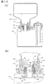
図16は、実施例1にかかる補給容器とインクジェット記録装置のインクサブ容器が接続された状態の一例を示す図である。   FIG. 16 is a diagram illustrating an example of a state where the supply container according to the first embodiment and the ink sub container of the ink jet recording apparatus are connected.

図16(a)は全体図、図16(b)は接続部の詳細図である。   FIG. 16A is an overall view, and FIG. 16B is a detailed view of a connecting portion.

インク補給容器301は貯蔵部材311の先端部322を下方に向けた状態でインクサブ容器202のアダプタ502に挿入され接続される。その接続は、インク補給容器301のシール部材314の円筒形状の内側面の環状突起362、363とアダプタ502の円筒部531の外側面の嵌合によるものであり、また、接続時にアダプタの円筒部の上部の鋭角形状532によって栓部材312は突き破られ、栓部材312は一部のつなぎ部541を残して環状に切り離される。このとき、栓部材の環状に切り離された内側の部分542は、アダプタ502の円筒部531によって押し上げられ、流路となるアダプタの円筒部531の内側を塞がない状態で維持される。シール部材314の底部368についても同様にアダプタ502の鋭角形状532によって突き破られ、一部のつなぎ部548を残して環状に切り離される。環状に切り離された内側の部分547は、アダプタ502の円筒部531によって押し上げられ、アダプタの円筒部531の内側の流路を塞がない状態を維持される。   The ink supply container 301 is inserted and connected to the adapter 502 of the ink sub-container 202 with the tip 322 of the storage member 311 facing downward. The connection is made by fitting the annular protrusions 362 and 363 on the inner surface of the cylindrical shape of the seal member 314 of the ink supply container 301 and the outer surface of the cylindrical portion 531 of the adapter 502. The plug member 312 is pierced by the acute angle shape 532 at the top of the plug member 312, and the plug member 312 is cut into an annular shape leaving a part of the connecting portion 541. At this time, the inner portion 542 of the plug member that is cut off in an annular shape is pushed up by the cylindrical portion 531 of the adapter 502 and is maintained in a state where the inner side of the cylindrical portion 531 of the adapter that becomes the flow path is not blocked. Similarly, the bottom portion 368 of the seal member 314 is also pierced by the acute angle shape 532 of the adapter 502 and is cut into an annular shape, leaving a part of the connecting portion 548. The inner portion 547 separated into the annular shape is pushed up by the cylindrical portion 531 of the adapter 502 and is maintained in a state where the flow path inside the cylindrical portion 531 of the adapter is not blocked.

接続させる操作としては、ユーザーがインク補給容器301から第2の蓋部材316を取り外した後、インク補給容器301の蓋部材313の円筒部351が、インクサブ容器202のアダプタの外壁部533の中に納まるように挿入後、インク補給容器301を下方に押し込む操作である。   As an operation to connect, after the user removes the second lid member 316 from the ink supply container 301, the cylindrical portion 351 of the lid member 313 of the ink supply container 301 enters the outer wall portion 533 of the adapter of the ink sub-container 202. This is an operation of pushing the ink supply container 301 downward after insertion so as to fit.

このとき、インクサブ容器301のアダプタの外壁部533は、その内径がインク補給容器301の蓋部材313の円筒部351の外径より大きいがその差が0.1〜1mm程度の近い寸法であり、またアダプタの円筒部531の外径は、蓋部材313の貫通穴353の内径より小さいがその差が0.1〜1mm程度の近い寸法であり、それぞれがインク補給容器301をアダプタに挿入する際の案内の役割をする。   At this time, the outer wall portion 533 of the adapter of the ink sub-container 301 has an inner diameter larger than the outer diameter of the cylindrical portion 351 of the lid member 313 of the ink supply container 301, but the difference is close to about 0.1 to 1 mm. Further, the outer diameter of the cylindrical portion 531 of the adapter is smaller than the inner diameter of the through hole 353 of the lid member 313, but the difference is close to about 0.1 to 1 mm. Each of them inserts the ink supply container 301 into the adapter. To serve as a guide.

インク補給容器301を押し込む際、インクサブ容器202のアダプタの円筒部531とインク補給容器301のシール部材314との間の摩擦力によって、またアダプタの円筒部531の鋭角部532が栓部材314を突き破るために要する力によって、ある程度の押し込み力が必要となるが、前記の操作でも押し込むことができる。   When the ink supply container 301 is pushed in, a frictional force between the cylindrical portion 531 of the adapter of the ink sub-container 202 and the seal member 314 of the ink supply container 301 causes the acute angle portion 532 of the cylindrical portion 531 of the adapter to break through the plug member 314. A certain amount of pushing force is required depending on the force required for this, but the pushing operation can also be performed by the above-described operation.

アダプタ502の円筒部531の外径は、インク補給容器の蓋部材313の貫通穴353の内径より小さいがほとんど同一寸法であり、またシール部材314の内側面の環状突起362、363の内径は、蓋部材の貫通穴353およびアダプタの円筒部531の外径より小さく、それにより前述したように当該部分のシール性が確保される。   The outer diameter of the cylindrical portion 531 of the adapter 502 is smaller than the inner diameter of the through hole 353 of the lid member 313 of the ink supply container, but is almost the same size. The inner diameters of the annular protrusions 362 and 363 on the inner surface of the seal member 314 are It is smaller than the outer diameters of the through hole 353 of the lid member and the cylindrical portion 531 of the adapter, thereby ensuring the sealing performance of the portion as described above.

これはすなわちインク補給容器301をインクサブ容器202に接続しインクを補給する際に、インクはインク補給容器の内部の環状突起362または363の部分でシールされてとどまり、インク補給容器の外面、例えば特に蓋部材313の底部352の外面546がインクで汚れないことを意味し、これによりユーザが使用済みのインク補給容器を取り扱う際に手がインク補給容器の任意の外面に触れても手をインクで汚さず作業することができる。   That is, when the ink supply container 301 is connected to the ink sub-container 202 and ink is supplied, the ink stays sealed at the portion of the annular protrusion 362 or 363 inside the ink supply container. This means that the outer surface 546 of the bottom portion 352 of the lid member 313 is not soiled with ink, so that when the user handles a used ink supply container, even if the hand touches any outer surface of the ink supply container, the hand is covered with ink. Work without getting dirty.

ここで、アダプタの円筒部531の外側面と栓部材312が突き破られてできた穴とは嵌合状態にあるが、円周の全周にわたって密接するとは限らず、当該部分のシール性は安定して確保できるものではない。接続時、アダプタの円筒部531の内側は流路となり、インク補給容器からインクサブ容器へインクをその自重で流し、同時に空気をインクサブ容器からインク補給容器へ流し、インク補給容器内部のインク流出により減少する分の体積を補う。その際、アダプタの円筒部531の内径が小さいと、インクが表面張力などの作用により流れ落ちない場合があり、アダプタの内径は約8mm以上が望ましい。   Here, the outer surface of the cylindrical portion 531 of the adapter and the hole formed by breaking through the plug member 312 are in a fitted state, but they are not necessarily in close contact over the entire circumference, and the sealing performance of the portion is It cannot be secured stably. When connecting, the inside of the cylindrical portion 531 of the adapter becomes a flow path, and the ink flows from the ink supply container to the ink sub-container by its own weight, and at the same time, air flows from the ink sub-container to the ink supply container, and decreases by the outflow of ink inside the ink supply container. Make up for the volume you want. At this time, if the inner diameter of the cylindrical portion 531 of the adapter is small, the ink may not flow down due to the action of surface tension or the like, and the inner diameter of the adapter is preferably about 8 mm or more.

また、本実施例においてはインク補給容器301の貯蔵部材311はある程度の剛性を有しており、インク補給容器301の容積はほとんど変わらないものであるが、その他の例としてインク補給容器の貯蔵部材311は剛性が小さく、内部のインクが自重で流出しようとする際発生する負圧や貯蔵部材311を加圧圧縮する外力によって容易に変形し容積が小さくなるものでもよい。   In this embodiment, the storage member 311 of the ink supply container 301 has a certain degree of rigidity, and the volume of the ink supply container 301 is almost the same. However, as another example, the storage member of the ink supply container 301 311 may have a small rigidity and may be easily deformed by a negative pressure generated when the ink inside is about to flow out by its own weight or an external force that compresses and compresses the storage member 311 to reduce the volume.

インク補給容器301は、インクサブ容器202と接続しその内部のほとんど全てのインクを流出させた後、ユーザによって引き上げられ新しいインクサブ容器と交換される。インク補給容器引き上げの際には、例えば栓部材312の上部スペース544やシール部材314の環状突起362の上部スペース545に残留していた少量のインクがシール部材314の貫通穴の内面を伝ってインク補給容器の外面に流れ出る恐れがあるが、それに対して吸収材をシール部材314と蓋部材313の間に配置したことによって、残留インクが流れ出ることを抑止している。   The ink replenishing container 301 is connected to the ink sub-container 202, and after almost all ink has flowed out, it is pulled up by the user and replaced with a new ink sub-container. When the ink supply container is pulled up, for example, a small amount of ink remaining in the upper space 544 of the plug member 312 or the upper space 545 of the annular protrusion 362 of the seal member 314 travels along the inner surface of the through hole of the seal member 314. Although there is a possibility of flowing out to the outer surface of the replenishing container, the absorbing material is disposed between the seal member 314 and the lid member 313 to prevent the residual ink from flowing out.

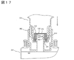
図17は、実施例1にかかる補給容器がインクジェット記録装置のインクサブ容器に接続される途中の状態の一例を示す図である。   FIG. 17 is a diagram illustrating an example of a state where the supply container according to the first embodiment is being connected to the ink sub container of the ink jet recording apparatus.

インク補給容器301は本体1内に固定されているインクサブ容器202に対し矢印方向に挿入されている途中である。このとき栓部材312とシール部材314はアダプタ502によって突破られる前であり、一方アダプタの円筒部531の外側面はシール部材314の環状突起363と円周に沿って連続的に密接しシール性を確保している。これはシール部材314の環状突起363が底部368に対し、貯蔵部材のより外側に配置されていたことによるものであり、これによってインク補給容器が接続される途中であっても外部へのインク漏れを防いでいる。   The ink supply container 301 is in the middle of being inserted in the arrow direction with respect to the ink sub container 202 fixed in the main body 1. At this time, the plug member 312 and the seal member 314 are before being pierced by the adapter 502, while the outer surface of the cylindrical portion 531 of the adapter is continuously in close contact with the annular protrusion 363 of the seal member 314 along the circumference to provide a sealing property. Secured. This is because the annular protrusion 363 of the seal member 314 is disposed on the outer side of the storage member with respect to the bottom portion 368, so that ink leakage to the outside can occur even while the ink supply container is being connected. Is preventing.

以上のことから、本実施例にかかる発明によれば、インクあるいは溶剤補給時等にインクあるいは溶剤による汚れを低減可能な補給容器を、より低コストで提供することができる。   From the above, according to the invention according to the present embodiment, it is possible to provide a replenishment container capable of reducing contamination due to ink or solvent at the time of replenishing ink or solvent at a lower cost.

図18は、実施例2にかかるインク補給容器の一例を示す図である。   FIG. 18 is a diagram illustrating an example of the ink supply container according to the second embodiment.

図18(a)はインク補給容器301の口部の構造を、図18(b)はインク補給容器301とインクサブ容器202との接続状態の一例を示している。   18A shows the structure of the mouth of the ink supply container 301, and FIG. 18B shows an example of the connection state between the ink supply container 301 and the ink sub-container 202.

インク補給容器301は貯蔵部材311、栓部材312、蓋部材313、シール部材551、吸収材552、第2の蓋部材316を備えている。本実施例は図1に関し前述した内容と同様であり、その際、シール部材314とシール部材551、吸収材315と吸収材552とがそれぞれ対応している。本実施例では、シール部材314と吸収材315の形状が一部変更されたものであり、変更部分について説明する。   The ink supply container 301 includes a storage member 311, a plug member 312, a lid member 313, a seal member 551, an absorbent material 552, and a second lid member 316. The present embodiment is the same as that described above with reference to FIG. 1, and in this case, the seal member 314 and the seal member 551 correspond to the absorbent material 315 and the absorbent material 552, respectively. In this embodiment, the shapes of the seal member 314 and the absorbent material 315 are partially changed, and the changed portions will be described.

吸収材552の貫通穴361の内径は、蓋部材313の貫通穴353の内径より小さく、インク補給容器301とインクサブ容器202との接続によって、アダプタの円筒部531が当該部分に挿入された際、アダプタの円筒部の外側面と吸収材の貫通穴の内側面が接触する関係である。   The inner diameter of the through hole 361 of the absorbent 552 is smaller than the inner diameter of the through hole 353 of the lid member 313, and when the cylindrical portion 531 of the adapter is inserted into the portion by connecting the ink supply container 301 and the ink sub container 202, The outer surface of the cylindrical portion of the adapter is in contact with the inner surface of the through hole of the absorbent material.

それによりインク補給容器301をインクサブ容器202から引き上げる過程で、シール部材551とアダプタ円筒部とのシール性を有する係合が外れ、前述のようなインク補給容器内に残留した少量のインクがインク補給容器外面に流れ出ようとした場合であっても、吸収材552により確実に該インクを捕らえることができ、また、吸収材552がアダプタの円筒部外側面と接触したまま円筒部の上方に移動することで、アダプタ円筒部の外側面に付着したインクを拭き取ることができる。シール部材551は、その貫通穴361と同心状の円形凹部561を有しており、円形凹部561は吸収材552と対面して配置される。円形凹部561の内径は、蓋部材313の貫通穴353の内径より大きく、それにより、インク補給容器301とインクサブ容器202との接続時、前述のようにアダプタ円筒部と吸収材の貫通穴の内面が密接することにより、吸収材552にめくれ部571が発生するがめくれ部571はシール部材の円形凹部561の中に収められ、めくれ部571がアダプタ円筒部とシール部材との密接部に巻き込まれることを防いでいる。吸収材552の固定方法としては、例えばシール部材551に設けられた突起部562によって吸収材552を押し込み、楔状の嵌合を形成し固定する。なお、図18に示す構造および図18に関し前述した内容は溶剤補給容器302にも適用できる。   As a result, in the process of pulling up the ink supply container 301 from the ink sub-container 202, the sealing member 551 and the adapter cylindrical portion are disengaged from each other, and a small amount of ink remaining in the ink supply container as described above is supplied. Even when it is about to flow out to the outer surface of the container, the ink can be reliably captured by the absorbent material 552, and the absorbent material 552 moves above the cylindrical portion while being in contact with the outer surface of the cylindrical portion of the adapter. Thus, the ink attached to the outer surface of the adapter cylindrical portion can be wiped off. The seal member 551 has a circular concave portion 561 concentric with the through hole 361, and the circular concave portion 561 is disposed to face the absorbent material 552. The inner diameter of the circular recess 561 is larger than the inner diameter of the through-hole 353 of the lid member 313, so that when the ink supply container 301 and the ink sub-container 202 are connected, as described above, the inner surface of the adapter cylindrical portion and the through-hole of the absorbent material Turns the absorbent member 552 to generate a turn-up portion 571. The turn-up portion 571 is housed in the circular recess 561 of the seal member, and the turn-up portion 571 is wound around the close contact portion between the adapter cylindrical portion and the seal member. It prevents that. As a method of fixing the absorbent material 552, for example, the absorbent material 552 is pushed in by a protrusion 562 provided on the seal member 551, and a wedge-shaped fitting is formed and fixed. The structure shown in FIG. 18 and the contents described above with reference to FIG. 18 can also be applied to the solvent supply container 302.

以上のことから、本実施例にかかる発明によれば、インクあるいは溶剤補給時等にインクあるいは溶剤による汚れを低減可能な補給容器を提供することができる。   From the above, according to the invention according to the present embodiment, it is possible to provide a replenishment container capable of reducing contamination due to ink or solvent when ink or solvent is replenished.

図19は、実施例3にかかるインク補給容器の一例を示す図である。    FIG. 19 is a diagram illustrating an example of the ink supply container according to the third embodiment.

図19(a)はインク補給容器651の口部の構造を、図19(b)はインク補給容器651とインクサブ容器202との接続状態の一例を示している。   FIG. 19A shows the structure of the mouth of the ink supply container 651, and FIG. 19B shows an example of the connection state between the ink supply container 651 and the ink sub-container 202.

インク補給容器651は貯蔵部材652、栓部材653、シール部材654、第1の蓋部材655、を備えている。貯蔵部材652、シール部材654、第1の蓋部材655の材質の例としては、それぞれ前述のインク補給容器301と同様のものが用いられる。栓部材653は一例として、図は省略するが、アルミ箔の層と熱可塑性樹脂層の二層からなり、熱可塑性樹脂層は貯蔵部材652の端面と結合している。結合手段としては例えば公知技術である高周波誘導加熱によるヒートシールが用いられる。シール部材654は第1の蓋部材655によって栓部材653に押し付けられ固定されている。   The ink supply container 651 includes a storage member 652, a plug member 653, a seal member 654, and a first lid member 655. Examples of the material of the storage member 652, the seal member 654, and the first lid member 655 are the same as those of the ink supply container 301 described above. As an example, the plug member 653 is not shown in the figure, but is composed of two layers of an aluminum foil layer and a thermoplastic resin layer, and the thermoplastic resin layer is bonded to the end face of the storage member 652. As the coupling means, for example, heat sealing by high frequency induction heating, which is a known technique, is used. The seal member 654 is fixed by being pressed against the plug member 653 by the first lid member 655.

インク補給容器651の栓部材653とシール部材654はインクサブ容器202との接続時にアダプタ502の円筒部531の上部の鋭角形状532によって突き破られ、それぞれ一部のつなぎ部661、662を残して環状に切り離される。このとき、栓部材とシール部材の環状に切り離された内側の部分663、664は、アダプタ502の円筒部531によって押し上げられ、流路となるアダプタの円筒部531の内側を塞がない状態で維持される。   The plug member 653 and the seal member 654 of the ink supply container 651 are pierced by the acute angle shape 532 at the upper part of the cylindrical portion 531 of the adapter 502 when connected to the ink sub-container 202, and leave the partial connection portions 661 and 662 respectively. Separated. At this time, the inner portions 663 and 664 of the plug member and the seal member which are separated in an annular shape are pushed up by the cylindrical portion 531 of the adapter 502 and are maintained without blocking the inner side of the cylindrical portion 531 of the adapter serving as the flow path. Is done.

このとき、シール部材654の突き破りによって生じた穴のとアダプタの円筒部531の外径の接触によって当該部からのインクの漏れを低減する。   At this time, the leakage of ink from the portion is reduced by the contact between the hole generated by the piercing of the seal member 654 and the outer diameter of the cylindrical portion 531 of the adapter.

本構成で用いられるシール部材654の製造方法の例としては、ゴム材料が公知技術であるカレンダー成形法によってシート状に成形された後、前述したようなポンチとダイやその他の打ち抜き型によるせん断加工が施されて所望形状に成形される。一般にこの製造方法は前述したコンプレッション成形による製造方法より生産性が高く、製造コストを抑えることができる。   As an example of the manufacturing method of the seal member 654 used in this configuration, after the rubber material is formed into a sheet shape by a known calendar molding method, the shearing process is performed by the punch and the die or other punching die as described above. Is formed into a desired shape. Generally, this manufacturing method has higher productivity than the manufacturing method by compression molding described above, and can suppress the manufacturing cost.

インク補給容器651は、栓部材653がなくてもよく、その際にはシール部材654が第1の蓋部材655によって貯蔵部材652の端面に押し付けられ、それにより貯蔵部材652からの漏れを防ぐことができる。   The ink supply container 651 may not have the stopper member 653, and in this case, the seal member 654 is pressed against the end surface of the storage member 652 by the first lid member 655, thereby preventing leakage from the storage member 652. Can do.

図20は、実施例4にかかるインク補給容器701の一例を示す図である。   FIG. 20 is a diagram illustrating an example of the ink supply container 701 according to the fourth embodiment.

図20(a)はインク補給容器701の口部の構造を、図20(b)はインク補給容器701とインクサブ容器202との接続状態の一例を示している。   20A shows the structure of the mouth of the ink supply container 701, and FIG. 20B shows an example of the connection state between the ink supply container 701 and the ink sub-container 202. FIG.

インク補給容器701は貯蔵部材702、栓部材703、第1の蓋部材704、を備えている。貯蔵部材702、、第1の蓋部材704の材質の例としては、前述のインク補給容器301と同様のものが用いられる。栓部材703は前述した栓部材653と同様の材質、固定方法が用いられる。   The ink supply container 701 includes a storage member 702, a plug member 703, and a first lid member 704. Examples of the material of the storage member 702 and the first lid member 704 are the same as those of the ink supply container 301 described above. The plug member 703 is made of the same material and fixing method as the plug member 653 described above.

貯蔵部材702の先端部711は円筒形状をしている。   The front end 711 of the storage member 702 has a cylindrical shape.

第1の蓋部材704は、第1の円筒部712、底部713、第2の円筒部714を有している。第1の円筒部712の内側にはねじが設けられており、貯蔵部材702に設けられたねじと嵌合し固定される。底部713は貯蔵部材702の端面に栓部材703を押さえつけている。第2の円筒部714は、貯蔵部材702の先端部711と同心状に配置され、第2の円筒部714の内径は貯蔵部材702の先端部711の内径より小さく、更にインクサブ容器202のアダプタ502の円筒部531の外径より小さい。また第2の円筒部714は栓部材703に対し、貯蔵部材702のより外側に配置される。   The first lid member 704 has a first cylindrical portion 712, a bottom portion 713, and a second cylindrical portion 714. A screw is provided inside the first cylindrical portion 712, and is fitted and fixed to a screw provided in the storage member 702. The bottom 713 holds the stopper member 703 against the end surface of the storage member 702. The second cylindrical portion 714 is disposed concentrically with the distal end portion 711 of the storage member 702, the inner diameter of the second cylindrical portion 714 is smaller than the inner diameter of the distal end portion 711 of the storage member 702, and the adapter 502 of the ink sub-container 202. This is smaller than the outer diameter of the cylindrical portion 531. The second cylindrical portion 714 is disposed on the outer side of the storage member 702 with respect to the plug member 703.

インク補給容器701の栓部材703はインクサブ容器202との接続時にアダプタ502の円筒部531の上部の鋭角形状532によって突き破られ、一部のつなぎ部721を残して環状に切り離される。このとき、栓部材の環状に切り離された内側の部分722は、アダプタ502の円筒部531によって押し上げられ、流路となるアダプタの円筒部531の内側を塞がない状態で維持される。   The plug member 703 of the ink supply container 701 is pierced by the acute angle shape 532 at the upper part of the cylindrical portion 531 of the adapter 502 when connected to the ink sub-container 202, and is separated into an annular shape leaving a part of the connecting portion 721. At this time, the inner portion 722 of the plug member that is cut off in an annular shape is pushed up by the cylindrical portion 531 of the adapter 502 and is maintained in a state in which the inner side of the cylindrical portion 531 of the adapter serving as the flow path is not blocked.

このとき、アダプタ502の円筒部531の外側面と第1の蓋部材704の第2の円筒部の内径は、1周連続的に密接しており、当該部からのインクの漏れを防いでいる。ここで、この密接部分の接触面圧が高いとインク補給容器652をインクサブ容器202に接続、取り外しする際に本部分の摩擦力が大きくなり、操作力が大きくなるため、第2の円筒部714の肉厚は1mm以下にすることが望ましい。また、第2の円筒部714の先端の内径は、アダプタ502の円筒部531の外径より大きくなっており、アダプタを案内しやすくなっている。   At this time, the outer surface of the cylindrical portion 531 of the adapter 502 and the inner diameter of the second cylindrical portion of the first lid member 704 are continuously in contact with each other, preventing ink leakage from the portion. . Here, when the contact surface pressure of the close contact portion is high, the friction force of the main portion increases when the ink supply container 652 is connected to or detached from the ink sub-container 202, and the operating force increases. Therefore, the second cylindrical portion 714 The wall thickness is desirably 1 mm or less. Further, the inner diameter of the tip of the second cylindrical portion 714 is larger than the outer diameter of the cylindrical portion 531 of the adapter 502, so that the adapter can be easily guided.

本構成では、前述のインク補給容器601に備えられるシール部材605の役割、すなわちインクサブ容器202にインク補給容器601を接続したにアダプタ502の円筒部531と係合してインク漏れを防ぐ機能を、第1の蓋部材704に一体的に成形された第2の円筒部714に持たせることで、ゴム製のシール部材314を不要とし、製造コストを低減している。   In this configuration, the role of the seal member 605 provided in the ink supply container 601 described above, that is, the function of preventing ink leakage by engaging with the cylindrical portion 531 of the adapter 502 when the ink supply container 601 is connected to the ink sub container 202, By providing the second cylindrical portion 714 integrally formed with the first lid member 704, the rubber seal member 314 is unnecessary, and the manufacturing cost is reduced.

図21は、実施例5にかかるインク補給容器731の一例を示す図である。   FIG. 21 is a diagram illustrating an example of the ink supply container 731 according to the fifth embodiment.

図21(a)はインク補給容器731の口部の構造を、図21(b)はインク補給容器731とインクサブ容器202との接続状態の一例を示している。   FIG. 21A shows the structure of the mouth of the ink supply container 731, and FIG. 21B shows an example of the connection state between the ink supply container 731 and the ink sub-container 202.

インク補給容器731は貯蔵部材732、栓部材733を備えている。貯蔵部材732、第1の蓋部材733の材質の例としては、それぞれ前述のインク補給容器301と同様のものが用いられる。   The ink supply container 731 includes a storage member 732 and a plug member 733. Examples of the material of the storage member 732 and the first lid member 733 are the same as those of the ink supply container 301 described above.

貯蔵部材732の先端部741は円筒形状をしている。   The distal end portion 741 of the storage member 732 has a cylindrical shape.

栓部材733は、第1の円筒部742、底部743、第2の円筒部744、円板部745、第3の円筒部746を有している。第1の円筒部742の内側にはねじが設けられており、貯蔵部材732に設けられたねじと嵌合し固定される。底部743は貯蔵部材732の端面を押さえつけている。第2の円筒部744は、貯蔵部材732の先端部741と同心状に配置され、第2の円筒部744の内径は貯蔵部材732の先端部741の内径より小さく、更にインクサブ容器202のアダプタ502の円筒部531の外径より小さい。円板部745は底部743の内側の穴を塞いでいる、第2の円筒部744は円板部745に対し、インク補給容器731のより外側に配置されている。第3の円筒部746は貯蔵部材732の先端部741の内側面と1周連続的に密接し当該部のシール性を確保している。   The plug member 733 includes a first cylindrical portion 742, a bottom portion 743, a second cylindrical portion 744, a disc portion 745, and a third cylindrical portion 746. A screw is provided inside the first cylindrical portion 742 and is fitted and fixed to a screw provided in the storage member 732. The bottom portion 743 presses the end surface of the storage member 732. The second cylindrical portion 744 is disposed concentrically with the distal end portion 741 of the storage member 732, the inner diameter of the second cylindrical portion 744 is smaller than the inner diameter of the distal end portion 741 of the storage member 732, and the adapter 502 of the ink sub-container 202. This is smaller than the outer diameter of the cylindrical portion 531. The disc portion 745 closes the inner hole of the bottom portion 743, and the second cylindrical portion 744 is disposed on the outer side of the ink supply container 731 with respect to the disc portion 745. The third cylindrical portion 746 is in close contact with the inner surface of the tip end portion 741 of the storage member 732 for one round to ensure the sealing performance of the portion.

インク補給容器731の栓部材733はインクサブ容器202との接続時にアダプタ502の円筒部531の上部の鋭角形状532によって突き破られ、一部のつなぎ部751を残して環状に切り離される。このとき、栓部材の環状に切り離された内側の部分752は、アダプタ502の円筒部531によって押し上げられ、流路となるアダプタの円筒部531の内側を塞がない状態で維持される。   The plug member 733 of the ink supply container 731 is pierced by the acute angle shape 532 at the top of the cylindrical portion 531 of the adapter 502 when connected to the ink sub-container 202, and is separated into an annular shape leaving a part of the connecting portion 751. At this time, the inner portion 752 of the plug member that is cut off in an annular shape is pushed up by the cylindrical portion 531 of the adapter 502 and is maintained in a state in which the inner side of the cylindrical portion 531 of the adapter serving as the flow path is not blocked.

このとき、アダプタ502の円筒部531の外側面と栓733の第2の円筒部744の内径は、1周連続的に密接しており、当該部からのインクの漏れを防いでいる。ここで、この密接部分の接触面圧が高いとインク補給容器731をインクサブ容器202に接続、取り外しする際に本部分の摩擦力が大きくなり、操作力が大きくなるため、第2の円筒部714の肉厚は1mm以下にすることが望ましい。また、第2の円筒部744の先端の内径は、アダプタ502の円筒部531の外径より大きくなっており、アダプタを案内しやすくなっている。   At this time, the outer surface of the cylindrical portion 531 of the adapter 502 and the inner diameter of the second cylindrical portion 744 of the plug 733 are in close contact with each other continuously to prevent ink leakage from the portion. Here, when the contact surface pressure of the close contact portion is high, the friction force of the main portion increases when the ink supply container 731 is connected to or detached from the ink sub-container 202, and the operating force increases. Therefore, the second cylindrical portion 714 The wall thickness is desirably 1 mm or less. In addition, the inner diameter of the tip of the second cylindrical portion 744 is larger than the outer diameter of the cylindrical portion 531 of the adapter 502, so that the adapter can be easily guided.

本構成では、前述のインク補給容器601に備えられるシール部材605の役割、すなわちインクサブ容器202にインク補給容器601を接続したときにアダプタ502の円筒部531と係合してインク漏れを防ぐ機能を、栓部材733に一体的に成形された第2の円筒部744に持たせることで、ゴム製のシール部材314を不要とし、製造コストを低減している。   In this configuration, the role of the sealing member 605 provided in the ink supply container 601 described above, that is, a function of preventing ink leakage by engaging with the cylindrical portion 531 of the adapter 502 when the ink supply container 601 is connected to the ink sub container 202. By providing the second cylindrical portion 744 integrally formed with the plug member 733, the rubber seal member 314 is unnecessary, and the manufacturing cost is reduced.

図22は、実施例6にかかるインク補給容器761の一例を示す図である。   FIG. 22 is a diagram illustrating an example of the ink supply container 761 according to the sixth embodiment.

図22(a)はインク補給容器761の口部の構造を、図22(b)はインク補給容器761とインクサブ容器202との接続状態の一例を示している。   FIG. 22A shows the structure of the mouth of the ink supply container 761, and FIG. 22B shows an example of the connection state between the ink supply container 761 and the ink sub-container 202.

インク補給容器761は貯蔵部材762、栓部材763、第1の蓋部材764を備えている。貯蔵部材762、栓部材763、第1の蓋部材764の材質の例としては、それぞれ前述のインク補給容器301と同様のものが用いられる。   The ink supply container 761 includes a storage member 762, a plug member 763, and a first lid member 764. Examples of the material of the storage member 762, the plug member 763, and the first lid member 764 are the same as those of the ink supply container 301 described above.

貯蔵部材762の先端部771は円筒形状をしている。   The tip 771 of the storage member 762 has a cylindrical shape.

栓部材763は、第1の円筒部772、底部773、第2の円筒部774、円板部775、環状凸形状776を有している。第1の円筒部772の内側にはねじが設けられており、貯蔵部材762に設けられたねじと嵌合し固定される。底部773は貯蔵部材762の端面を押さえつけている。第2の円筒部774は貯蔵部材762の先端部771の内側面と1周連続的に密接し、当該部のシール性を確保している。円板部775は第2の円筒部774の内側の穴を塞いでいる。環状凸形状776は、貯蔵部材762の先端部771と同心状に配置され、環状凸形状776の内径は貯蔵部材762の先端部771の内径より小さく、更にインクサブ容器202のアダプタ502の円筒部531の外径より小さい。環状凸形状776は、円板部775に対し、インク補給容器761のより外側に配置されている。   The plug member 763 has a first cylindrical portion 772, a bottom portion 773, a second cylindrical portion 774, a disc portion 775, and an annular convex shape 776. A screw is provided inside the first cylindrical portion 772, and is fitted and fixed to a screw provided on the storage member 762. The bottom 773 presses the end surface of the storage member 762. The second cylindrical portion 774 is in continuous contact with the inner surface of the tip portion 771 of the storage member 762 continuously for one round, and ensures the sealing performance of the portion. The disc part 775 closes the hole inside the second cylindrical part 774. The annular convex shape 776 is disposed concentrically with the distal end portion 771 of the storage member 762, the inner diameter of the annular convex shape 776 is smaller than the inner diameter of the distal end portion 771 of the storage member 762, and the cylindrical portion 531 of the adapter 502 of the ink sub-container 202. Is smaller than the outer diameter. The annular convex shape 776 is disposed on the outer side of the ink supply container 761 with respect to the disc portion 775.

インク補給容器761の栓部材763はインクサブ容器202との接続時にアダプタ502の円筒部531の上部の鋭角形状532によって突き破られ、一部のつなぎ部781を残して環状に切り離される。このとき、栓部材の環状に切り離された内側の部分782は、アダプタ502の円筒部531によって押し上げられ、流路となるアダプタの円筒部531の内側を塞がない状態で維持される。   The plug member 763 of the ink supply container 761 is pierced by the acute angle shape 532 at the upper part of the cylindrical portion 531 of the adapter 502 when connected to the ink sub-container 202, and is separated into an annular shape leaving a part of the connecting portion 781. At this time, the inner portion 782 of the plug member that is cut off in an annular shape is pushed up by the cylindrical portion 531 of the adapter 502 and is maintained in a state where the inner side of the cylindrical portion 531 of the adapter serving as the flow path is not blocked.

このとき、アダプタ502の円筒部531の外側面と栓733の環状凸形状776の内側面は、1周連続的に密接しており、当該部からのインクの漏れを防いでいる。   At this time, the outer surface of the cylindrical portion 531 of the adapter 502 and the inner surface of the annular convex shape 776 of the plug 733 are in close contact with each other continuously, preventing ink leakage from the portion.

本構成では、前述のインク補給容器601に備えられるシール部材605の役割、すなわちインクサブ容器202にインク補給容器601を接続したときにアダプタ502の円筒部531と係合してインク漏れを防ぐ機能を、栓部材763の環状凸形状776に持たせることで、ゴム製のシール部材314を不要とし、製造コストを低減している。   In this configuration, the role of the sealing member 605 provided in the ink supply container 601 described above, that is, a function of preventing ink leakage by engaging with the cylindrical portion 531 of the adapter 502 when the ink supply container 601 is connected to the ink sub container 202. By providing the annular convex shape 776 of the plug member 763, the rubber seal member 314 is unnecessary, and the manufacturing cost is reduced.

1…本体、2…インク吐出ヘッド、3…操作表示部、4…導管、5…状態表示灯、6…メンテナンス扉、13…印字対象物、15…ベルトコンベア、16…エンコーダ、17…印字センサ、100…インクジェット記録装置、101…MPU、102…ROM、103…RAM、104…入力装置、105…表示装置、111…励振電圧発生回路、112…帯電電圧発生回路、113…偏向電圧発生回路、114…電磁弁制御回路、115…ポンプ制御回路、116…液面制御回路、151…ノズル、152…励振素子、153…帯電電極、154…偏向電極、161…インク粒子、201…インク容器、202…インクサブ容器、203…溶剤サブ容器、211、212、213
、214…ポンプ、221、222、223、224、225、226、227、228…電磁弁、229…三方電磁弁、231…フィルター、232…減圧弁、233…圧力計、234…粘度計、241…ガター、251…インク循環エリア、261…インク循環ユニット、301…インク補給容器、302…溶剤補給容器、311…貯蔵部材、312…栓部材、313…第1の蓋部材、314…シール部材、315…吸収材、316…第2の蓋部材、321…貯蔵室、322…先端部、331…円筒部、332…鍔部、333…底部、341…薄肉部、351…円筒部、352…底部、353…貫通穴、354…円、355…円に沿った部分、356…凹である部分、361…穴、362、363…環状突起、364、365…環状突起、371…貫通穴の内径、372、373…環状突起の内径、381…貫通穴、382…円、383…凹である部分、391…円筒部、392…底部、393…環状突起、401〜406…液面制御フロー、411…円形断面部、412…底部、421…栓部材、422…第1の蓋部材、426…凸部、427…凸部、451…上部金型、452…下部金型、453…ゴム材料、461…所望形状部、462…シート部、471…ポンチ、472…ダイ、480…切断箇所、481…バリ、501…貯蔵部材、502…アダプタ、503…ねじ、504…シール部材、505…液面センサ、506…吸引パイプ、507…大気開放パイプ、508…ブロック、509…蓋、511…貯蔵部、512…補給口、513…センサ口、521…検出レベル、522…吸引口、531…円筒部、532…鋭角形状、533…外壁部、541…つなぎ部、542…環状に切り離された内側の部分、544…栓部材の上部スペース、545…環状突起の上部スペース、546…底部の外面、547…環状に切り離された内側の部分、548…つなぎ部、551…シール部材、552…吸収材、561…円形凹部、571…めくれ部、601…インク補給容器、602…貯蔵部材、603…栓部材、604…第1の蓋部材、605…シール部材、606…液吸収材、607…第2の蓋部材、651…インク補給容器、652…貯蔵部材、653…栓部材、654…シール部材、655…第1の蓋部材、661…つなぎ部、662…つなぎ部、663…環状に切り離された内側の部分、664…環状に切り離された内側の部分、701…インク補給容器、702…貯蔵部材、703…栓部材、704…第1の蓋部材、711…先端部、712…第1の円筒部、713…底部、714…第2の円筒部、721…つなぎ部、722…環状に切り離された内側の部分、731…インク補給容器、732…貯蔵部材、733…栓部材、741…先端部、742…第1の円筒部、743…底部、744…第2の円筒部、745…円板部、746…第3の円筒部、751…つなぎ部、752…環状に切り離された内側の部分、761…インク補給容器、762…貯蔵部材、763…栓部材、764…第1の蓋部材、771…先端部、772…第1の円筒部、773…底部、774…第2の円筒部、775…円板部、776…環状凸形状、781…つなぎ部、782…環状に切り離された内側の部分
DESCRIPTION OF SYMBOLS 1 ... Main body, 2 ... Ink discharge head, 3 ... Operation display part, 4 ... Conduit, 5 ... Status indicator lamp, 6 ... Maintenance door, 13 ... Print object, 15 ... Belt conveyor, 16 ... Encoder, 17 ... Print sensor , 100: inkjet recording device, 101: MPU, 102: ROM, 103: RAM, 104: input device, 105: display device, 111: excitation voltage generation circuit, 112: charging voltage generation circuit, 113 ... deflection voltage generation circuit, DESCRIPTION OF SYMBOLS 114 ... Solenoid valve control circuit, 115 ... Pump control circuit, 116 ... Liquid level control circuit, 151 ... Nozzle, 152 ... Excitation element, 153 ... Charging electrode, 154 ... Deflection electrode, 161 ... Ink particle, 201 ... Ink container, 202 ... Ink sub container, 203 ... Solvent sub container, 211, 212, 213
, 214 ... Pump, 221, 222, 223, 224, 225, 226, 227, 228 ... Solenoid valve, 229 ... Three-way solenoid valve, 231 ... Filter, 232 ... Pressure reducing valve, 233 ... Pressure gauge, 234 ... Viscometer, 241 ... Gutter, 251 ... Ink circulation area, 261 ... Ink circulation unit, 301 ... Ink supply container, 302 ... Solvent supply container, 311 ... Storage member, 312 ... Plug member, 313 ... First lid member, 314 ... Seal member, 315 ... Absorbing material, 316 ... Second lid member, 321 ... Storage chamber, 322 ... Tip, 331 ... Cylindrical part, 332 ... Gutter part, 333 ... Bottom part, 341 ... Thin wall part, 351 ... Cylindrical part, 352 ... Bottom part 353 ... Through hole, 354 ... circle, 355 ... part along the circle, 356 ... concave part, 361 ... hole, 362,363 ... annular protrusion, 364,365 ... annular protrusion 371: Inner diameter of through hole, 372, 373 ... Inner diameter of annular protrusion, 381 ... Through hole, 382 ... Circle, 383 ... Recessed part, 391 ... Cylindrical part, 392 ... Bottom part, 393 ... Annular protrusion, 401-406 ... Liquid level control flow, 411 ... circular cross section, 412 ... bottom, 421 ... plug member, 422 ... first lid member, 426 ... convex, 427 ... convex, 451 ... upper mold, 452 ... lower mold, 453 ... Rubber material, 461 ... Desired shape part, 462 ... Sheet part, 471 ... Punch, 472 ... Die, 480 ... Cutting part, 481 ... Burr, 501 ... Storage member, 502 ... Adapter, 503 ... Screw, 504 ... Seal member 505 ... Liquid level sensor, 506 ... Suction pipe, 507 ... Air release pipe, 508 ... Block, 509 ... Lid, 511 ... Storage part, 512 ... Supply port, 513 ... Sensor port, 521 ... Detection Bell, 522 ... Suction port, 531 ... Cylindrical part, 532 ... Sharp angle shape, 533 ... Outer wall part, 541 ... Linking part, 542 ... Inner part separated in an annular shape, 544 ... Upper space of the plug member, 545 ... Annular projection ,...,...,..., A crevice, 601... Ink supply Container, 602... Storage member, 603... Plug member, 604... First lid member, 605... Seal member, 606... Liquid absorbing material, 607 ... second lid member, 651. 653... Plug member, 654... Seal member, 655... First lid member, 661 .. Linking portion, 662 .. Linking portion, 663. Separated inner part, 701 ... ink supply container, 702 ... storage member, 703 ... plug member, 704 ... first lid member, 711 ... tip portion, 712 ... first cylindrical portion, 713 ... bottom portion, 714 ... Second cylindrical portion, 721... Linking portion, 722... Inner portion separated in an annular shape, 731... Ink supply container, 732... Storage member, 733 .. Plug member, 741. 743 ... bottom part, 744 ... second cylindrical part, 745 ... disc part, 746 ... third cylindrical part, 751 ... connecting part, 752 ... inner part separated in an annular shape, 761 ... ink supply container, 762 ... storage member, 763 ... plug member, 764 ... first lid member, 771 ... tip part, 772 ... first cylindrical part, 773 ... bottom part, 774 ... second cylindrical part, 775 ... disc part, 776 ... An annular convex shape, 781... 782 ... portion of the inner that is isolated to the annular

Claims (19)

液体を貯蔵する貯蔵室を有し、開口部が形成された貯蔵部材と、
前記貯蔵部材の開口部を封止する栓部材と、
前記栓部材を覆う蓋部材と、
前記栓部材と前記蓋部材の間に備えられたシール部材とを有し、
前記シール部材は円筒部と円筒部の内側の穴を塞ぐ底部を有し、
前記蓋部材は、前記シール部材の円筒部と同心状に空けられた貫通穴を有し、前記シール部材の円筒部の一部あるいは全部の内径は前記蓋部材の貫通穴の内径より小さいことを特徴とする補給容器。
A storage member having a storage chamber for storing a liquid and having an opening formed therein;
A plug member for sealing the opening of the storage member;
A lid member covering the plug member;
A seal member provided between the plug member and the lid member;
The sealing member has a cylindrical portion and a bottom portion that closes a hole inside the cylindrical portion,
The lid member has a through hole concentrically formed with the cylindrical portion of the seal member, and an inner diameter of a part or all of the cylindrical portion of the seal member is smaller than an inner diameter of the through hole of the lid member. Feature replenishment container.
請求項1に記載の補給容器であって、
前記シール部材の円筒部の内径側に凸部を有し、その凸部は内径部に沿って1周連続的につながっていることを特徴とする補給容器
The supply container according to claim 1,
A replenishing container having a convex portion on the inner diameter side of the cylindrical portion of the seal member, the convex portion being continuously connected one round along the inner diameter portion.
請求項1または2に記載の補給容器であって、
前記シール部材の円筒部の方が前記シール部材の底部よりも、前記貯蔵部材の外側に配置されることを特徴とする補給容器。
The supply container according to claim 1 or 2,
The supply container according to claim 1, wherein the cylindrical portion of the seal member is disposed outside the storage member rather than the bottom portion of the seal member.
請求項1または2に記載の補給容器であって、
前記シール部材の円筒部の内側の凸部の方が前記シール部材の底部よりも、前記貯蔵部材の外側に配置されることを特徴とする補給容器。
The supply container according to claim 1 or 2,
The replenishing container, wherein the convex portion on the inner side of the cylindrical portion of the seal member is disposed outside the storage member rather than the bottom portion of the seal member.
請求項1乃至4のいずれかに記載の補給容器であって、
前記シール部材は弾性体であることを特徴とする補給容器。
A supply container according to any one of claims 1 to 4,
The supply container, wherein the seal member is an elastic body.
請求項1乃至5のいずれかに記載の補給容器であって、
前記シール部材と前記蓋部材の間に、前記蓋部材に設けられた貫通穴と同心状の貫通穴を有する吸収材を備えることを特徴とする補給容器。
A supply container according to any one of claims 1 to 5,
A supply container comprising an absorbent having a through hole concentric with a through hole provided in the lid member between the seal member and the lid member.
請求項6に記載の補給容器であって、
前記吸収材の貫通穴の内径が前記蓋部材の貫通穴の内径より小さいことを特徴とする補給容器。
The supply container according to claim 6,
A supply container, wherein an inner diameter of the through hole of the absorbent material is smaller than an inner diameter of the through hole of the lid member.
請求項7に記載の補給容器であって、
前記シール部材と前記吸収材との間に間隙があることを特徴とする補給容器。
The supply container according to claim 7,
A supply container having a gap between the seal member and the absorbent.
請求項6乃至8のいずれかに記載の補給容器であって、
前記シール部材の一端部に突起が設けられており、前記突起が前記吸収材と接続していることを特徴とする補給容器。
A supply container according to any one of claims 6 to 8,
A supply container, wherein a protrusion is provided at one end of the seal member, and the protrusion is connected to the absorbent material.
インクまたは溶剤を貯蔵する貯蔵室を有し、開口部が形成された貯蔵部材と、
前記貯蔵部材の開口部を封止する栓部材と、
前記栓部材を覆う蓋部材を備える補給容器であって、
前記栓部材と蓋部材の間にシール部材を備え、
前記蓋部材は前記貯蔵部材の開口と同心状の貫通穴を有することを特徴とする補給容器。
A storage member having a storage chamber for storing ink or solvent and having an opening formed therein;
A plug member for sealing the opening of the storage member;
A replenishment container comprising a lid member covering the plug member,
A sealing member is provided between the plug member and the lid member,
The lid member has a through hole concentric with the opening of the storage member.
請求項10に記載の補給容器であって、
前記栓部材は熱可塑性樹脂層を有しており、前記栓部材と前記貯蔵部材の開口部は溶着により接続していることを特徴とする補給容器。
The supply container according to claim 10, wherein
The plug member has a thermoplastic resin layer, and the opening of the plug member and the storage member is connected by welding.
請求項10または11に記載の補給容器であって、
前記シール部材は弾性体であることを特徴とする補給容器。
A supply container according to claim 10 or 11,
The supply container, wherein the seal member is an elastic body.
請求項12に記載の補給容器であって、
前記シール部材はシート状ゴムであることを特徴とする補給容器。
A supply container according to claim 12,
The supply container, wherein the sealing member is a sheet-like rubber.
インクまたは溶剤を貯蔵する貯蔵室を有し、開口部が形成された貯蔵部材と、
前記貯蔵部材の開口部を封止する栓部材と、
前記栓部材を覆う蓋部材を備える補給容器であって、
前記蓋部材は前記貯蔵部材の開口と同心状の円筒部を有し、円筒部の内径の一部は貯蔵部材の開口部の内径よりも小さいことを特徴とする補給容器。
A storage member having a storage chamber for storing ink or solvent and having an opening formed therein;
A plug member for sealing the opening of the storage member;
A replenishment container comprising a lid member covering the plug member,
The lid member has a cylindrical portion concentric with the opening of the storage member, and a part of the inner diameter of the cylindrical portion is smaller than the inner diameter of the opening of the storage member.
請求項14に記載の補給容器であって、
前記蓋部材の円筒部の内側は貫通穴であることを特徴とする補給容器。
15. A supply container according to claim 14, wherein
A replenishing container, wherein the inside of the cylindrical portion of the lid member is a through hole.
請求項14に記載の補給容器であって、
前記栓部材は熱可塑性樹脂層を有しており、前記栓部材と前記貯蔵部材の開口部が溶着されていることを特徴とする補給容器。
15. A supply container according to claim 14, wherein
The plug member has a thermoplastic resin layer, and an opening of the plug member and the storage member is welded.
請求項14に記載の補給容器であって、
前記栓部材と前記蓋部材が一体的に形成され、前記栓部材が前記蓋部材の円筒部の穴を塞いでいることを特徴とする補給容器。
15. A supply container according to claim 14, wherein
The replenishing container, wherein the stopper member and the lid member are integrally formed, and the stopper member closes a hole in a cylindrical portion of the lid member.
請求項14に記載の補給容器であって、
前記栓部材に対し、貯蔵部材のより内側に配置される円筒部を有し、この円筒部は前記貯蔵部材の開口部の内側面と1周連続的に接触していることを特徴とする補給容器。
15. A supply container according to claim 14, wherein
A replenishment characterized in that the plug member has a cylindrical portion disposed on the inner side of the storage member, and the cylindrical portion is in continuous contact with the inner surface of the opening of the storage member for one round. container.
インクを噴出するノズルと、
前記ノズルから噴出されたインクを帯電する帯電電極と、
前記帯電電極により帯電されたインクを偏向する偏向電極と、を備えるインクジェット記録装置であって、
請求項1乃至18のいずれかに記載の補給容器を搭載したことを特徴とするインクジェット記録装置。
A nozzle for ejecting ink;
A charging electrode for charging ink ejected from the nozzle;
An inkjet recording apparatus comprising: a deflection electrode that deflects ink charged by the charging electrode;
An ink jet recording apparatus comprising the supply container according to claim 1.
JP2016086725A 2016-04-25 2016-04-25 Replenishing container and ink jet recording device having the same Pending JP2017197197A (en)

Priority Applications (2)

Application Number Priority Date Filing Date Title
JP2016086725A JP2017197197A (en) 2016-04-25 2016-04-25 Replenishing container and ink jet recording device having the same
CN201710203011.3A CN107303759B (en) 2016-04-25 2017-03-30 Compensation tank and the ink-jet recording apparatus for having the compensation tank

Applications Claiming Priority (1)

Application Number Priority Date Filing Date Title
JP2016086725A JP2017197197A (en) 2016-04-25 2016-04-25 Replenishing container and ink jet recording device having the same

Publications (1)

Publication Number Publication Date
JP2017197197A true JP2017197197A (en) 2017-11-02

Family

ID=60150832

Family Applications (1)

Application Number Title Priority Date Filing Date
JP2016086725A Pending JP2017197197A (en) 2016-04-25 2016-04-25 Replenishing container and ink jet recording device having the same

Country Status (2)

Country Link
JP (1) JP2017197197A (en)
CN (1) CN107303759B (en)

Cited By (3)

* Cited by examiner, † Cited by third party
Publication number Priority date Publication date Assignee Title
JP2018144230A (en) * 2017-03-01 2018-09-20 セイコーエプソン株式会社 Ink Supply Container
JP2018161887A (en) * 2017-03-27 2018-10-18 セイコーエプソン株式会社 Ink refill auxiliary device and ink refill device
JP2021130488A (en) * 2020-02-19 2021-09-09 キヤノン株式会社 Liquid storage bottle

Families Citing this family (2)

* Cited by examiner, † Cited by third party
Publication number Priority date Publication date Assignee Title
CN111936313A (en) * 2018-05-15 2020-11-13 惠普发展公司,有限责任合伙企业 Outlet mechanism for fluid container
TWI684535B (en) * 2019-04-18 2020-02-11 臺灣納米科技股份有限公司 Joint structure of ink bag

Citations (10)

* Cited by examiner, † Cited by third party
Publication number Priority date Publication date Assignee Title
JPS4926862U (en) * 1972-06-13 1974-03-07
JPS5022992U (en) * 1973-06-25 1975-03-14
JPS56166279U (en) * 1980-05-13 1981-12-09
DE29521731U1 (en) * 1995-06-22 1998-06-10 Dia Nielsen Gmbh & Co Kg Zubeh Refillable liquid container, especially ink cartridge
JP2001206419A (en) * 2000-01-31 2001-07-31 Yoshino Kogyosho Co Ltd Inner stopper
US20030099573A1 (en) * 2001-11-26 2003-05-29 Lab Vision Corporation Automated tissue staining system and reagent container
WO2010113823A1 (en) * 2009-03-30 2010-10-07 学校法人近畿大学 Container plug
US20130314475A1 (en) * 2012-05-25 2013-11-28 Franklin S. Love, III Resistor Protected Deflection Plates For Liquid Jet Printer
WO2015079547A1 (en) * 2013-11-29 2015-06-04 株式会社日立産機システム Replenishment container and inkjet recording device comprising same
WO2016038357A1 (en) * 2014-09-08 2016-03-17 Eulysis Uk Limited Container and closure

Family Cites Families (5)

* Cited by examiner, † Cited by third party
Publication number Priority date Publication date Assignee Title
CN1442306A (en) * 2002-03-02 2003-09-17 珠海天威飞马打印耗材有限公司 Special sealing ring for ink box
JP5384211B2 (en) * 2009-06-12 2014-01-08 株式会社日立産機システム Filter and ink jet recording apparatus having the same
JP5365466B2 (en) * 2009-10-21 2013-12-11 凸版印刷株式会社 Stretch blow-molded container with inner-sealed sealed outlet
CN102126351A (en) * 2011-01-05 2011-07-20 武汉镭德杰科技发展有限公司 Ink box structure of inkjet printing machine
JP6294033B2 (en) * 2013-08-30 2018-03-14 株式会社日立産機システム Liquid container and ink jet recording apparatus provided with the same

Patent Citations (10)

* Cited by examiner, † Cited by third party
Publication number Priority date Publication date Assignee Title
JPS4926862U (en) * 1972-06-13 1974-03-07
JPS5022992U (en) * 1973-06-25 1975-03-14
JPS56166279U (en) * 1980-05-13 1981-12-09
DE29521731U1 (en) * 1995-06-22 1998-06-10 Dia Nielsen Gmbh & Co Kg Zubeh Refillable liquid container, especially ink cartridge
JP2001206419A (en) * 2000-01-31 2001-07-31 Yoshino Kogyosho Co Ltd Inner stopper
US20030099573A1 (en) * 2001-11-26 2003-05-29 Lab Vision Corporation Automated tissue staining system and reagent container
WO2010113823A1 (en) * 2009-03-30 2010-10-07 学校法人近畿大学 Container plug
US20130314475A1 (en) * 2012-05-25 2013-11-28 Franklin S. Love, III Resistor Protected Deflection Plates For Liquid Jet Printer
WO2015079547A1 (en) * 2013-11-29 2015-06-04 株式会社日立産機システム Replenishment container and inkjet recording device comprising same
WO2016038357A1 (en) * 2014-09-08 2016-03-17 Eulysis Uk Limited Container and closure

Cited By (5)

* Cited by examiner, † Cited by third party
Publication number Priority date Publication date Assignee Title
JP2018144230A (en) * 2017-03-01 2018-09-20 セイコーエプソン株式会社 Ink Supply Container
JP2018161887A (en) * 2017-03-27 2018-10-18 セイコーエプソン株式会社 Ink refill auxiliary device and ink refill device
JP7147198B2 (en) 2017-03-27 2022-10-05 セイコーエプソン株式会社 Ink replenishment auxiliary device and ink replenishment device
JP2021130488A (en) * 2020-02-19 2021-09-09 キヤノン株式会社 Liquid storage bottle
US11820560B2 (en) 2020-02-19 2023-11-21 Canon Kabushiki Kaisha Liquid storage bottle

Also Published As

Publication number Publication date
CN107303759B (en) 2019-12-03
CN107303759A (en) 2017-10-31

Similar Documents

Publication Publication Date Title
JP6158346B2 (en) Supply container and ink jet recording apparatus provided with the same
JP2017197197A (en) Replenishing container and ink jet recording device having the same
US8591012B2 (en) Liquid ejection apparatus
TWI590996B (en) Spout
JP5223740B2 (en) Liquid container
US8083334B2 (en) Liquid storage container and refilling method using the same
KR20180091870A (en) Refill container
CN103448371B (en) The manufacture method of ink re-fill method, print cartridge and print cartridge
JP5830333B2 (en) Discharge container
KR102099256B1 (en) Recycling hazardous liquid storage container system
WO1999011462A1 (en) Ink cartridge having waste ink absorbing function
KR20010096615A (en) Ink cartridge for recording apparatus
US8833914B2 (en) Image recording apparatus and liquid cartridge
CN105365396A (en) Liquid cartridge
US20160059572A1 (en) Liquid cartridge
US9217342B2 (en) Collecting container for lubricants
JP6200484B2 (en) Plug systems, plugs and containers with plugs
US9308732B2 (en) Vent for a liquid container
CN203401814U (en) Regenerating ink cartridge
JP3692831B2 (en) Ink jet recording apparatus, ink bag, and ink remaining amount detection method
JP6253471B2 (en) Joining device for inkjet printer
JP6127654B2 (en) Liquid cartridge
CN108025819B (en) Filling device
JP2019107775A (en) Flow passage member, liquid injection device, and manufacturing method for flow passage member
JP2013056692A (en) Cartridge for fluid substance

Legal Events

Date Code Title Description
A521 Request for written amendment filed

Free format text: JAPANESE INTERMEDIATE CODE: A523

Effective date: 20160425

RD04 Notification of resignation of power of attorney

Free format text: JAPANESE INTERMEDIATE CODE: A7424

Effective date: 20170120

RD04 Notification of resignation of power of attorney

Free format text: JAPANESE INTERMEDIATE CODE: A7424

Effective date: 20170126

A621 Written request for application examination

Free format text: JAPANESE INTERMEDIATE CODE: A621

Effective date: 20180827

A521 Request for written amendment filed

Free format text: JAPANESE INTERMEDIATE CODE: A523

Effective date: 20180828

A977 Report on retrieval

Free format text: JAPANESE INTERMEDIATE CODE: A971007

Effective date: 20190606

A131 Notification of reasons for refusal

Free format text: JAPANESE INTERMEDIATE CODE: A131

Effective date: 20190611

A601 Written request for extension of time

Free format text: JAPANESE INTERMEDIATE CODE: A601

Effective date: 20190807

A521 Request for written amendment filed

Free format text: JAPANESE INTERMEDIATE CODE: A523

Effective date: 20190808

A02 Decision of refusal

Free format text: JAPANESE INTERMEDIATE CODE: A02

Effective date: 20200121