JP2017196650A - Pressing device - Google Patents
Pressing device Download PDFInfo
- Publication number
- JP2017196650A JP2017196650A JP2016090940A JP2016090940A JP2017196650A JP 2017196650 A JP2017196650 A JP 2017196650A JP 2016090940 A JP2016090940 A JP 2016090940A JP 2016090940 A JP2016090940 A JP 2016090940A JP 2017196650 A JP2017196650 A JP 2017196650A
- Authority
- JP
- Japan
- Prior art keywords
- lower mold
- axis
- support part
- mold support
- chip
- Prior art date
- Legal status (The legal status is an assumption and is not a legal conclusion. Google has not performed a legal analysis and makes no representation as to the accuracy of the status listed.)
- Granted
Links
Images


Classifications
-
- B—PERFORMING OPERATIONS; TRANSPORTING
- B30—PRESSES
- B30B—PRESSES IN GENERAL
- B30B15/00—Details of, or accessories for, presses; Auxiliary measures in connection with pressing
- B30B15/32—Discharging presses
-
- B—PERFORMING OPERATIONS; TRANSPORTING
- B21—MECHANICAL METAL-WORKING WITHOUT ESSENTIALLY REMOVING MATERIAL; PUNCHING METAL
- B21D—WORKING OR PROCESSING OF SHEET METAL OR METAL TUBES, RODS OR PROFILES WITHOUT ESSENTIALLY REMOVING MATERIAL; PUNCHING METAL
- B21D45/00—Ejecting or stripping-off devices arranged in machines or tools dealt with in this subclass
- B21D45/02—Ejecting devices
-
- B—PERFORMING OPERATIONS; TRANSPORTING
- B29—WORKING OF PLASTICS; WORKING OF SUBSTANCES IN A PLASTIC STATE IN GENERAL
- B29C—SHAPING OR JOINING OF PLASTICS; SHAPING OF MATERIAL IN A PLASTIC STATE, NOT OTHERWISE PROVIDED FOR; AFTER-TREATMENT OF THE SHAPED PRODUCTS, e.g. REPAIRING
- B29C43/00—Compression moulding, i.e. applying external pressure to flow the moulding material; Apparatus therefor
- B29C43/02—Compression moulding, i.e. applying external pressure to flow the moulding material; Apparatus therefor of articles of definite length, i.e. discrete articles
- B29C43/04—Compression moulding, i.e. applying external pressure to flow the moulding material; Apparatus therefor of articles of definite length, i.e. discrete articles using movable moulds
-
- B—PERFORMING OPERATIONS; TRANSPORTING
- B30—PRESSES
- B30B—PRESSES IN GENERAL
- B30B11/00—Presses specially adapted for forming shaped articles from material in particulate or plastic state, e.g. briquetting presses, tabletting presses
- B30B11/02—Presses specially adapted for forming shaped articles from material in particulate or plastic state, e.g. briquetting presses, tabletting presses using a ram exerting pressure on the material in a moulding space
- B30B11/04—Presses specially adapted for forming shaped articles from material in particulate or plastic state, e.g. briquetting presses, tabletting presses using a ram exerting pressure on the material in a moulding space co-operating with a fixed mould
-
- B—PERFORMING OPERATIONS; TRANSPORTING
- B30—PRESSES
- B30B—PRESSES IN GENERAL
- B30B15/00—Details of, or accessories for, presses; Auxiliary measures in connection with pressing
- B30B15/04—Frames; Guides
- B30B15/047—C-shaped frames
-
- B—PERFORMING OPERATIONS; TRANSPORTING
- B29—WORKING OF PLASTICS; WORKING OF SUBSTANCES IN A PLASTIC STATE IN GENERAL
- B29B—PREPARATION OR PRETREATMENT OF THE MATERIAL TO BE SHAPED; MAKING GRANULES OR PREFORMS; RECOVERY OF PLASTICS OR OTHER CONSTITUENTS OF WASTE MATERIAL CONTAINING PLASTICS
- B29B17/00—Recovery of plastics or other constituents of waste material containing plastics
-
- B—PERFORMING OPERATIONS; TRANSPORTING
- B29—WORKING OF PLASTICS; WORKING OF SUBSTANCES IN A PLASTIC STATE IN GENERAL
- B29C—SHAPING OR JOINING OF PLASTICS; SHAPING OF MATERIAL IN A PLASTIC STATE, NOT OTHERWISE PROVIDED FOR; AFTER-TREATMENT OF THE SHAPED PRODUCTS, e.g. REPAIRING
- B29C43/00—Compression moulding, i.e. applying external pressure to flow the moulding material; Apparatus therefor
- B29C43/32—Component parts, details or accessories; Auxiliary operations
- B29C2043/3272—Component parts, details or accessories; Auxiliary operations driving means
- B29C2043/3283—Component parts, details or accessories; Auxiliary operations driving means for moving moulds or mould parts
-
- B—PERFORMING OPERATIONS; TRANSPORTING
- B30—PRESSES
- B30B—PRESSES IN GENERAL
- B30B1/00—Presses, using a press ram, characterised by the features of the drive therefor, pressure being transmitted directly, or through simple thrust or tension members only, to the press ram or platen
- B30B1/18—Presses, using a press ram, characterised by the features of the drive therefor, pressure being transmitted directly, or through simple thrust or tension members only, to the press ram or platen by screw means
Landscapes
- Engineering & Computer Science (AREA)
- Mechanical Engineering (AREA)
- Press Drives And Press Lines (AREA)
- Processing Of Solid Wastes (AREA)
- Shaping Metal By Deep-Drawing, Or The Like (AREA)
- Braking Arrangements (AREA)
Abstract
Description
本発明はプレス装置に関し、より具体的には切屑排出機能を備えたプレス装置に関する。 The present invention relates to a press device, and more specifically to a press device having a chip discharging function.
この種のプレス装置の切屑排出装置として、プレス成形により生じた切屑をベルトコンベヤにより所定の切屑排出位置まで搬送するものが知られている(例えば、特許文献1参照。)。
また、加工テーブルと同一の面を形成するワークシュータの蓋と、当該蓋を支持すると共に当該蓋を水平な位置から傾斜位置まで移動させる蓋支持手段とを備え、当該蓋を傾斜させることにより切屑を所定の切屑排出位置に移動させる切屑排出装置が知られている(例えば、特許文献2参照。)。
As a chip discharge device of this type of press apparatus, one that conveys chips generated by press molding to a predetermined chip discharge position by a belt conveyor is known (for example, see Patent Document 1).
In addition, a work shooter lid that forms the same surface as the processing table, and a lid support means for supporting the lid and moving the lid from a horizontal position to an inclined position, and chipping by tilting the lid. There is known a chip discharging device that moves a chip to a predetermined chip discharging position (for example, see Patent Document 2).
型上に残った切屑を上記の切屑排出装置に移動させるために、例えば下型を前記ベルトコンベヤやワークシュータの蓋の上方に移動させ、下型を回転させることが考えられる。この場合、下型の回転角度が大きいほど下型上の切屑が落ち易くなるので有利であるが、下型のサイズや形状によってはベルトコンベヤやワークシュータと干渉するため、下型の回転角度を確保できない場合があった。 In order to move the chips remaining on the mold to the above-described chip discharge device, for example, it is conceivable to move the lower mold above the lid of the belt conveyor or the work shoe and rotate the lower mold. In this case, the larger the rotation angle of the lower mold, the easier it is for chips on the lower mold to fall off.However, depending on the size and shape of the lower mold, it interferes with the belt conveyor and work shooter. In some cases, it could not be secured.
このような状況を改善するため、切屑が滑り落ちる樋上の切屑シューターを設け、下型からベルトコンベヤやワークシュータに切屑シューターを用いて切屑を運ぶことも考えられる。切屑シューターにより前記干渉を避ける構造とすることは可能であるが、下型とベルトコンベヤやワークシュータとの距離が離れている場合は、切屑シューターに大きな傾斜角度を設けることが難しく、切屑が切屑シューター内に止まってしまう。 In order to improve such a situation, it is also conceivable to provide a chip shooter on the ridge where the chips slide down, and carry the chips from the lower mold to the belt conveyor or work shooter using the chip shooter. It is possible to use a chip shooter to avoid the interference, but when the distance between the lower mold and the belt conveyor or work shooter is long, it is difficult to provide a large tilt angle to the chip shooter, It stops in the shooter.
さらに、前記ベルトコンベヤやワークシュータを用いると、切屑を所定の切屑排出位置に移動させるために、ベルトコンベヤを回転させるモータや蓋を傾斜させる駆動手段が必要であり、切屑シューターの傾斜角度が小さい場合も切屑シューター上で切屑を移動させるための振動源等が必要となる。つまり、切屑を移動させる専用の動力源が必要になり、その制御も必要になるので、切屑排出機構の製造コストが高くつく。さらに、下型と切屑排出位置とが近い場合には、当該近距離の移動のために前記専用の動力源を用いることになり、非効率的である。 Further, when the belt conveyor or the work shooter is used, in order to move the chips to a predetermined chip discharge position, a motor for rotating the belt conveyor and a driving means for tilting the lid are necessary, and the tilt angle of the chip shooter is small. In some cases, a vibration source or the like for moving the chips on the chip shooter is required. In other words, a dedicated power source for moving the chips is required, and the control thereof is also required, which increases the manufacturing cost of the chip discharging mechanism. Furthermore, when the lower mold is close to the chip discharge position, the dedicated power source is used for the movement of the short distance, which is inefficient.
本発明は、このような事情に鑑みてなされたものであって、下型上の切屑を効率的に排出することのできるプレス装置を提供することを目的とする。 This invention is made | formed in view of such a situation, Comprising: It aims at providing the press apparatus which can discharge | emit the chip on a lower mold efficiently.
上記課題を解決するために、本発明は以下の手段を採用する。
本発明の第1の態様のプレス装置は、フレームと、該フレームに対し上下方向に移動するプレス軸と、該フレームに第1の軸線周りに回動可能に取付けられ、前記プレス軸の下端部に取付けられた上型に対応するように下型を支持する下型支持部と、該下型支持部を前記第1の軸線周りに回動させる下型支持部回動手段と、該下型支持部の回動方向に配置され、前記下型支持部回動手段によって前記下型支持部を回動させて前記下型が下方に向かって傾いた際に前記下型から落下する切屑を受ける切屑シューターと、一端部が前記下型支持部に第2の軸線周りに回動可能に連結されたリンク部材とを備え、前記切屑シューターの一端側が前記リンク部材の他端部に第3の軸線周りに回動可能に連結され、前記切屑シューターの他端側が前記フレーム又は他の支持部材に第4の軸線周りに回動可能に支持されている。
In order to solve the above problems, the present invention employs the following means.
A press device according to a first aspect of the present invention includes a frame, a press shaft that moves in the vertical direction with respect to the frame, and is attached to the frame so as to be rotatable about a first axis, and a lower end portion of the press shaft A lower mold support portion for supporting the lower mold so as to correspond to the upper mold attached to the lower mold, a lower mold support section rotating means for rotating the lower mold support section around the first axis, and the lower mold Arranged in the direction of rotation of the support part, the lower mold support part is rotated by the lower mold support part rotation means to receive chips falling from the lower mold when the lower mold is tilted downward. A chip shooter, and a link member having one end rotatably connected to the lower mold support portion around a second axis, the one end of the chip shooter being a third axis on the other end of the link member The chip shooter is connected to the other end side of the chip shooter so as to be rotatable. It is rotatably supported to the fourth axis around the over arm or other support member.
当該態様では、下型支持部回動手段により下型支持部を第1の軸線周りに回動させると、下型支持部に支持された下型が傾斜し、これにより下型に残った切屑が切屑シューター上に落下し易くなる。
また、当該態様では、リンク部材の一端が下型支持部に第1の軸線とは異なる第2の軸線周りに回動可能に連結されている。また、リンク部材と切屑シューターとは第2の軸線と第4の軸線との間の第3の軸線周りに相対的に回動可能である。このため、下型上の切屑を切屑シューターに落下させるために下型支持部を切屑シューター側に回動させると、水平方向において例えば第2の軸線が第4の軸線に対して近づく方向に移動し、リンク部材と切屑シューターとが第3の軸線周りに相対的に回動する。
In this aspect, when the lower mold support part is rotated about the first axis by the lower mold support part rotating means, the lower mold supported by the lower mold support part is inclined, and thereby the chips remaining in the lower mold Can easily fall onto the chip shooter.
Moreover, in the said aspect, the end of a link member is connected with the lower mold | type support part so that rotation around the 2nd axis line different from a 1st axis line is possible. Further, the link member and the chip shooter are relatively rotatable around a third axis between the second axis and the fourth axis. For this reason, when the lower mold support part is rotated to the chip shooter side in order to drop the chips on the lower mold onto the chip shooter, the second axis moves in a direction approaching the fourth axis in the horizontal direction. Then, the link member and the chip shooter rotate relatively around the third axis.
つまり、下型支持部の回動に応じて切屑シューターの一端側が上下方向に移動し、例えば、下型上の切屑を切屑シューターに落下させるために下型支持部を切屑シューター側に回動させた時に、切屑シューターの一端側が下方に移動し、下型支持部を下型が上型に対応するように元の位置に戻した際に、切屑シューターの一端側が上方に移動する。
このように、下型支持部の回動に連動して切屑シューターの一端側が上下方向に移動するので、切屑シューター上で切屑を移動させる専用の動力源を設けなくても、切屑シューター上に切屑が止まることを防止することが可能となり、製造コストの低減を図ることも可能となる。
That is, one end side of the chip shooter moves in the vertical direction according to the rotation of the lower mold support part.For example, the lower mold support part is rotated to the chip shooter side in order to drop the chip on the lower mold onto the chip shooter. The one end side of the chip shooter moves downward, and when the lower mold support portion is returned to the original position so that the lower mold corresponds to the upper mold, one end side of the chip shooter moves upward.
In this way, one end side of the chip shooter moves in the vertical direction in conjunction with the rotation of the lower mold support part. Therefore, even if there is no dedicated power source for moving the chips on the chip shooter, the chips on the chip shooter Can be prevented, and the manufacturing cost can be reduced.
上記態様において、前記第1、第2、第3、および第4の軸線は平行であることが好ましい。
このように構成すると、簡易な構成で下型支持部の回動と切屑シューターの一端側の上下方向の移動をスムーズに連動させることができる。
In the above aspect, the first, second, third, and fourth axes are preferably parallel.
If comprised in this way, rotation of a lower mold | type support part and the movement of the up-down direction of the one end side of a chip shooter can be smoothly interlocked with a simple structure.
上記態様において、前記プレス軸がサーボモータにより上下方向に移動し、前記下型支持部回動手段がサーボモータによって駆動されることが好ましい。
このように、プレス軸の上下方向の移動や下型支持部の回動の位置を簡易な構成で制御可能となるので、プレス軸や下型支持部を必用最小限の動作範囲で動かすことが可能となり、これはサイクルタイムの短縮に繋がる。
In the above aspect, it is preferable that the press shaft is moved in the vertical direction by a servo motor, and the lower mold support rotating means is driven by the servo motor.
As described above, since the vertical movement of the press shaft and the rotation position of the lower mold support portion can be controlled with a simple configuration, the press shaft and the lower mold support portion can be moved within the minimum necessary operating range. This is possible, leading to a reduction in cycle time.
上記態様において、前記下型支持部が、前記下型支持部回動手段によって前記下型支持部を回動させた際に前記下型から前記切屑を剥がすイジェクタを有することが好ましい。
これにより、下型支持部の回動だけでは除去し難い切屑も下型から剥がすことが可能となる。
The said aspect WHEREIN: It is preferable that the said lower mold support part has an ejector which peels off the said chip from the said lower mold, when the said lower mold support part is rotated by the said lower mold support part rotation means.
As a result, it is possible to peel off chips that are difficult to remove by only rotating the lower mold support portion from the lower mold.
上記態様において、前記イジェクタが、前記下型支持部に支持された前記下型から突出するように前記下型支持部内に配置されたイジェクタピンと、該イジェクタピンを前記下型から突出するように移動させるエアシリンダとを有することが好ましい。
これにより、除去し難い切屑を剥がす機構を小型化および軽量化することが可能となり、その分だけ下型支持部の小型化および軽量化も可能となり、下型支持部の動作性能が向上する。
In the above aspect, the ejector pin disposed in the lower mold support part so as to protrude from the lower mold supported by the lower mold support part, and the ejector pin moves so as to protrude from the lower mold It is preferable to have an air cylinder.
As a result, it is possible to reduce the size and weight of the mechanism for peeling off the chips that are difficult to remove, and to reduce the size and weight of the lower mold support portion accordingly, and to improve the operating performance of the lower mold support portion.
本発明によれば、下型上の切屑を効率的に排出することができる。 According to the present invention, chips on the lower mold can be efficiently discharged.
本発明の一実施形態に係るプレス装置を、図面を参照しながら以下に説明する。
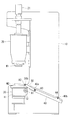
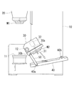
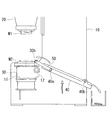
このプレス装置は、図1および図2に示すように、基部に設置されるフレーム10と、フレーム10に上下方向に移動するように設けられ、下端にプレス成形用の上型M1が取付けられたプレス軸20と、フレーム10に取付けられ、プレス軸20の下端に取付けられた上型M1に対応するように下型M2が取付けられる下型支持部30と、フレーム10に支持された切屑シューター40と、一端部が下型支持部30に連結され他端部が切屑シューター40に連結された一対のリンク部材50とを備えている。
A press apparatus according to an embodiment of the present invention will be described below with reference to the drawings.
As shown in FIG. 1 and FIG. 2, the press device is provided with a
プレス軸20はフレーム10に上下方向に移動するように支持され、プレス軸20を上下方向に移動させる機構としては、油圧シリンダによりプレス軸20を上下方向に移動させる公知の機構を用いても良く、サーボモータとボールねじ等のスクリューとを用いてプレス軸20を上下方向に移動させる公知の機構を用いても良い。また、サーボモータ、スクリュー、およびリンクを用いてプレス軸20を上下方向に移動させる公知の機構を用いても良く、モータとクランク又はカムとを用いてプレス軸20を上下方向に移動させる公知の機構を用いても良い。
The
本実施形態では、例えば、プレス軸20内にその軸方向に延びる雌ねじ穴が設けられると共に、当該雌ねじ穴にフレーム10に回転可能に支持されたボールスクリューが螺合している。また、当該ボールスクリューの上端部にプーリや歯車が固定され、当該プーリや歯車に減速機を介してサーボモータ21の回転力が伝達される。プレス軸20はフレーム10に対する回転が規制されており、ボールスクリューはフレーム10に対する上下方向の移動が規制されている。これにより、サーボモータ21を回転させると、プレス軸20が上下方向に移動する。
In the present embodiment, for example, a female screw hole extending in the axial direction is provided in the
下型支持部30はフレーム10の支持面11により下方から支持されると共に、フレーム10に第1の軸線A1周りに回動可能に取付けられている。例えば、下型支持部30の一部には水平方向に延びる支軸12が挿通すると共に固定され、支軸12がフレーム10に回動可能に支持され、これにより下型支持部30がフレーム10に支軸12の中心軸周りに回動可能に取付けられている。フレーム10と支軸12との間には好ましくはベアリング等の軸受が設けられている。
The lower
下型支持部30の上面にはプレス成形用の下型M2が取付けられている。また、下型支持部30内には図8に示すようにイジェクタピン31と、イジェクタピン31を上下方向に移動させるエアシリンダ32とが設けられている。これらはイジェクタを構成する。下型支持部30内には上下方向に延びるようにイジェクタピン用孔30aが設けられ、下型M2にもイジェクタ用孔30aに対応した位置に上下方向に延びる孔が設けられている。イジェクタピン31はイジェクタピン用孔30a内に配置されている。エアシリンダ32により、イジェクタピン31は、その先端が下型M2の孔から突出する位置と当該先端が下型M2の孔から突出しない位置とに移動する。
A lower mold M2 for press molding is attached to the upper surface of the lower
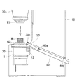
各リンク部材50の一端部は下型支持部30に第2の軸線A2周りに回動可能に連結されている。例えば、下型支持部30に水平方向に延びる一対の軸30bが設けられ、当該一対の軸にそれぞれ各リンク部材50の一端部が回動可能に連結され、これにより各リンク部材50が下型支持部30に各軸30bの中心軸周りに回動可能に連結されている。
One end portion of each
各リンク部材50の他端部は切屑シューター40の一端側に第3の軸線A3周りに回動可能に連結されている。例えば、切屑シューター40の一端側に水平方向に延びる一対の軸40aが設けられ、当該一対の軸40aにそれぞれ各リンク部材50の他端部が回動可能に連結され、これにより各リンク部材50が切屑シューター40に各軸40aの中心軸周りに回動可能に連結されている。
The other end of each
切屑シューター40の他端側はフレーム10に第4の軸線A4周りに回動可能に連結されている。例えば、切屑シューター40の他端側に水平方向に延びる一対の軸40bが設けられ、当該一対の軸40bがそれぞれフレーム10に回動可能に連結され、これにより切屑シューター40の他端側がフレーム10に各軸40bの中心軸周りに回動可能に連結されている。本実施形態では、第1〜第4の軸線A1〜A4は水平方向又は略水平方向に延びている。
The other end side of the
フレーム10にはサーボモータから成る下型支持部回動装置13が固定され、下型支持部回動装置13により支軸12が回転されるように構成されている。つまり、下型支持部30は下型支持部回動装置13により支持面11を離れて切屑シューター40側に回動し、また、下型支持部回動装置13により支持面11側にも回動する。
The
第2の軸線A2はその直交方向において第1の軸線A1と異なる位置に配置されている。このため、下型支持部30の回動に応じて、第2の軸線A2の位置が水平方向において切屑シューター40側や支持面側に移動する。
第3の軸線A3は水平方向において第2の軸線A2と第4の軸線A4との間に配置されている。また、第1の軸線A1と第4の軸線A4はフレーム10により位置が固定されているので、下型支持部30が回動しても第1の軸線A1と第4の軸線A4との間の距離は変化しない。
The second axis A2 is arranged at a position different from the first axis A1 in the orthogonal direction. For this reason, according to rotation of the lower mold |
The third axis A3 is disposed between the second axis A2 and the fourth axis A4 in the horizontal direction. In addition, since the positions of the first axis A1 and the fourth axis A4 are fixed by the
このため、下型支持部30の下面が支持面11に支持されている状態から、下型支持部30が下型支持部回動装置13により切屑シューター40側に回動すると、第2の軸線A2と第4の軸線A4との距離が短くなり、その分だけ第3の軸線A3が下方に移動する。つまり、切屑シューター40の一端側が下方に移動する。一方、下型支持部30の下面が支持面11に接触するように回動すると、第2の軸線A2と第4の軸線A4との間の距離が長くなり、その分だけ第3の軸線A3が上方に移動する。つまり、切屑シューター40の他端側が上方に移動する。
For this reason, when the lower
続いて、図を参照しながら上記プレス装置の動作を説明する。
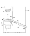
先ず、図3のように、プレス軸20が上方に位置している状態で、ロボット等のワーク搬送装置や作業者がワークWを下型M2上に載置する。そして、プレス成形動作が開始されると、図4のようにプレス軸20が下方に移動して上型M1および下型M2の間でワークWの切断、孔空け、塑性変形等の加工が行われた後、図5のようにプレス軸20が上方に移動する。ワーク搬送装置や作業者は加工されたワークWを下型M2上から他の場所に移動させる。
Subsequently, the operation of the press apparatus will be described with reference to the drawings.
First, as shown in FIG. 3, a workpiece transfer device such as a robot or an operator places the workpiece W on the lower mold M2 in a state where the
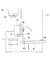
この時、下型M2上に前記加工等により生ずるワークの切屑が残る場合がある。このプレス装置は、図6のように下型支持部回動装置13が下型支持部30を切屑シューター40側に回動させる。これにより、下型支持部30上の下型M2が切屑シューター40側に傾く。支持面11に当接している位置からの下型支持部30の回動角度は特に限定されないが、好ましくは90°以上回動することが好ましい。これにより、下型M2上の切屑が落下し易い状態となる。
At this time, there may be a case where workpiece chips generated by the above processing or the like remain on the lower mold M2. In this press apparatus, as shown in FIG. 6, the lower mold support
また、図7および図8のように、下型M2が切屑シューター40上に配置されるまで下型支持部30を回動させることが好ましい。続いて、図7又は図8の状態で、エアシリンダ32によりイジェクタピン31を下型M2から突出させる。これにより、下型M2から落ちずに残っている切屑を切屑シューター40に落とすことが可能となる。
Moreover, it is preferable to rotate the lower mold |
この後、図9に示すように、エアシリンダ32によりイジェクタピン31を下型M2から突出しない状態とし、下型支持部回動装置13により下型支持部30の下面を支持面11に当接させる。これにより、前述のように第2の軸線A2と第4の軸線A4との距離が長くなり、切屑シューター40の他端側が上方に移動する。これは、切屑シューター40上に切屑がとどまることを防上する上で有利である。
Thereafter, as shown in FIG. 9, the
このように、本実施形態によれば、下型支持部回動装置13により下型支持部30を第1の軸線A1周りに回動させると、下型支持部30に支持された下型M2が傾斜し、これにより下型M2に残った切屑が切屑シューター40上に落下し易くなる。
また、本実施形態では、リンク部材50の一端が下型支持部30に第1の軸線A1とは異なる第2の軸線A2周りに回動可能に連結されている。また、リンク部材50と切屑シューター40とは第2の軸線A2と第4の軸線A4との間の第3の軸線A3周りに相対的に回動可能である。
Thus, according to this embodiment, when the lower
In the present embodiment, one end of the
このため、下型M2上の切屑を切屑シューター40に落下させるために下型支持部30を切屑シューター40側に回動させると、水平方向において第2の軸線A2が第4の軸線A4に対して近づく方向に移動し、リンク部材50と切屑シューター40とが第3の軸線A3周りに相対的に回動する。
つまり、下型支持部30の回動に応じて切屑シューター40の一端側が上下方向に移動し、例えば、下型M2上の切屑を切屑シューター40に落下させるために下型支持部30を切屑シューター40側に回動させた時に、切屑シューター40の一端側が下方に移動し、下型支持部30を下型M2が上型M1に対応するように元の位置に戻した際に、切屑シューター40の一端側が上方に移動する。
For this reason, when the lower
That is, one end side of the
このように、下型支持部30の回動に連動して切屑シューター40の一端側が上下方向に移動するので、切屑シューター40上で切屑を移動させる専用の動力源を設けなくても、切屑シューター40上に切屑が止まることを防止することが可能となり、製造コストの低減を図ることも可能となる。
As described above, the one end side of the
また、本実施形態では、軸線A1〜A4は平行である。このような構成は、下型支持部回動装置13により下型支持部30を回動させた際に、切屑シューター40を上下に円滑に移動させる上で有利である。なお、各軸線A1〜A4が平行でない場合であっても、各リンク部材50や切屑シューター40をスムーズに動かすことは可能である。
In the present embodiment, the axes A1 to A4 are parallel. Such a configuration is advantageous in smoothly moving the
また、プレス軸20はサーボモータにより上下方向に移動し、下型支持部回動装置13もサーボモータによって構成されている。このため、プレス軸20の上下方向の移動や下型支持部30の回動の位置を簡易な構成で制御可能となるので、プレス軸20や下型支持部30を必用最小限の動作範囲で動かすことが可能となり、これはサイクルタイムの短縮に繋がる。
Further, the
また、下型支持部30が、下型支持部回動装置13によって下型支持部30を回動させた際に下型M2から切屑を剥がすイジェクタ機構であるイジェクタピン31とエアシリンダ32とを有する。これにより、下型支持部30の回動だけでは除去し難い切屑も下型M2から剥がすことが可能となる。
Further, when the lower
また、下型支持部30に支持された前記下型M2から突出するように下型支持部30内に配置されたイジェクタピン31と、イジェクタピン31を下型M2から突出するように移動させるエアシリンダ32とを用いて、下型M2から切屑を剥がす機構が構成されている。このため、除去し難い切屑を剥がす機構を小型化および軽量化することが可能となり、その分だけ下型支持部30の小型化および軽量化も可能となり、下型支持部30の動作性能が向上する。
Further, an
なお、上記実施形態では、下型支持部回動装置13にサーボモータを用いたが、下型支持部30を回動させることができれば他の種類のモータ、シリンダ等の如何なる駆動手段も用いることが可能である。
また、上記実施形態では、イジェクタピン31およびエアシリンダ32を用いて下型M2上に残った切屑を除去するようにしたが、イジェクタピン31およびエアシリンダ32の代わりに圧縮空気を用いて残った切屑を除去することも可能であり、その他の方法で残った切屑に力を加えて除去することも可能である。
In the above embodiment, a servo motor is used for the lower mold support
Further, in the above embodiment, the chips remaining on the lower mold M2 are removed using the
また、切屑シューター40の他端側をフレーム10以外の支持部材、例えば基部に固定された柱等に第4の軸線A4周りに回動可能に支持することも可能であり、この場合でも上記と同様に機能する。
It is also possible to support the other end side of the
10 フレーム
11 支持面
12 支軸
13 下型支持部回動装置
20 プレス軸
21 サーボモータ
30 下型支持部
31 イジェクタピン
32 エアシリンダ
40 切屑シューター
50 リンク部材
A1 第1の軸線
A2 第2の軸線
A3 第3の軸線
A4 第4の軸線
DESCRIPTION OF
Claims (5)
該フレームに対し上下方向に移動するプレス軸と、
該フレームに第1の軸線周りに回動可能に取付けられ、前記プレス軸の下端部に取付けられた上型に対応するように下型を支持する下型支持部と、
該下型支持部を前記第1の軸線周りに回動させる下型支持部回動手段と、
該下型支持部の回動方向に配置され、前記下型支持部回動手段によって前記下型支持部を回動させて前記下型が下方に向かって傾いた際に前記下型から落下する切屑を受ける切屑シューターと、
一端部が前記下型支持部に第2の軸線周りに回動可能に連結されたリンク部材とを備え、
前記切屑シューターの一端側が前記リンク部材の他端部に第3の軸線周りに回動可能に連結され、前記切屑シューターの他端側が前記フレーム又は他の支持部材に第4の軸線周りに回動可能に支持されているプレス装置。 Frame,
A press shaft that moves vertically with respect to the frame;
A lower mold support portion attached to the frame so as to be rotatable around a first axis, and supporting a lower mold so as to correspond to an upper mold attached to a lower end portion of the press shaft;
Lower mold support part rotating means for rotating the lower mold support part around the first axis;
The lower mold support part is arranged in the rotation direction, and the lower mold support part is rotated by the lower mold support part rotating means, and when the lower mold is tilted downward, the lower mold is dropped from the lower mold. A chip shooter that receives chips,
A link member connected at one end to the lower mold support portion so as to be rotatable around a second axis;
One end of the chip shooter is connected to the other end of the link member so as to be rotatable about a third axis, and the other end of the chip shooter is rotated about the fourth axis to the frame or another support member. A pressing device supported as possible.
Priority Applications (4)
| Application Number | Priority Date | Filing Date | Title |
|---|---|---|---|
| JP2016090940A JP6342944B2 (en) | 2016-04-28 | 2016-04-28 | Press machine |
| CN201710235615.6A CN107335738B (en) | 2016-04-28 | 2017-04-12 | Stamping device |
| US15/490,195 US10166735B2 (en) | 2016-04-28 | 2017-04-18 | Press machine |
| DE102017108330.8A DE102017108330B4 (en) | 2016-04-28 | 2017-04-19 | pressing machine |
Applications Claiming Priority (1)
| Application Number | Priority Date | Filing Date | Title |
|---|---|---|---|
| JP2016090940A JP6342944B2 (en) | 2016-04-28 | 2016-04-28 | Press machine |
Publications (2)
| Publication Number | Publication Date |
|---|---|
| JP2017196650A true JP2017196650A (en) | 2017-11-02 |
| JP6342944B2 JP6342944B2 (en) | 2018-06-13 |
Family
ID=60081756
Family Applications (1)
| Application Number | Title | Priority Date | Filing Date |
|---|---|---|---|
| JP2016090940A Active JP6342944B2 (en) | 2016-04-28 | 2016-04-28 | Press machine |
Country Status (4)
| Country | Link |
|---|---|
| US (1) | US10166735B2 (en) |
| JP (1) | JP6342944B2 (en) |
| CN (1) | CN107335738B (en) |
| DE (1) | DE102017108330B4 (en) |
Cited By (1)
| Publication number | Priority date | Publication date | Assignee | Title |
|---|---|---|---|---|
| US10632705B2 (en) | 2017-11-07 | 2020-04-28 | Fanuc Corporation | Press apparatus |
Families Citing this family (5)
| Publication number | Priority date | Publication date | Assignee | Title |
|---|---|---|---|---|
| JP6922466B2 (en) * | 2017-06-20 | 2021-08-18 | トヨタ紡織株式会社 | Work piece manufacturing equipment |
| CN110394437A (en) * | 2018-04-25 | 2019-11-01 | 河南摩西机械制造有限公司 | A kind of casting iron pan die casting robot |
| CN111922165B (en) * | 2020-10-19 | 2021-07-02 | 苏州泽宇科技有限公司 | Stamping die is used in production of metal tray |
| CN117282815B (en) * | 2023-11-24 | 2024-02-02 | 烟台大兴钢结构有限公司 | A profiling machine for steel grating plate processing |
| CN118237460A (en) * | 2024-04-24 | 2024-06-25 | 威海津恒科技有限公司 | Stamping die with waste recycling function |
Citations (5)
| Publication number | Priority date | Publication date | Assignee | Title |
|---|---|---|---|---|
| JPS59180826U (en) * | 1983-05-18 | 1984-12-03 | 富士通機電株式会社 | Removal mechanism for pressed products |
| JPH0347628U (en) * | 1989-09-11 | 1991-05-02 | ||
| JPH06114466A (en) * | 1992-10-08 | 1994-04-26 | Amada Co Ltd | Turret punch press |
| JP2005262294A (en) * | 2004-03-19 | 2005-09-29 | Toyota Motor Corp | Workpiece carrying away apparatus |
| JP2015085359A (en) * | 2013-10-31 | 2015-05-07 | ダイハツ工業株式会社 | Scrap chute |
Family Cites Families (13)
| Publication number | Priority date | Publication date | Assignee | Title |
|---|---|---|---|---|
| DE3439316A1 (en) * | 1984-10-26 | 1986-04-30 | Bayrisches Druckgußwerk Thurner GmbH & Co KG, 8015 Markt Schwaben | PUNCHING DEVICE |
| US5044919A (en) * | 1988-12-09 | 1991-09-03 | Honda Giken Kogyo Kabushiki Kaisha | Synthetic resin molding apparatus |
| JP2560099Y2 (en) * | 1990-11-28 | 1998-01-21 | セントラル自動車株式会社 | Press lifter device |
| JPH08187530A (en) | 1994-12-29 | 1996-07-23 | Kanto Auto Works Ltd | Device for recovering scrap in press machine |
| US6209431B1 (en) * | 1998-10-14 | 2001-04-03 | John L. Wickham | Automated degate and trim machine |
| JP2000141159A (en) | 1998-11-12 | 2000-05-23 | Amada Eng Center Co Ltd | Work chute device |
| DE10225528A1 (en) * | 2002-06-10 | 2004-01-08 | G+K Umformtechnik Gmbh | trimming |
| KR20110042643A (en) * | 2009-10-19 | 2011-04-27 | 권병수 | Trimming press |
| KR20120034397A (en) * | 2010-10-01 | 2012-04-12 | 삼성전자주식회사 | Apparatus for discharging scrap of pressing mold |
| CN202606740U (en) * | 2012-05-03 | 2012-12-19 | 宁波信泰机械有限公司 | Unloading assembly |
| JP5998077B2 (en) * | 2013-02-13 | 2016-09-28 | 本田技研工業株式会社 | Cutting device |
| CN203664450U (en) * | 2014-01-12 | 2014-06-25 | 刘宪福 | Rotary extrusion machine |
| CN104550543B (en) * | 2015-01-23 | 2016-08-24 | 太原科技大学 | Automatization's discharging of a kind of metal sheet shearing machine, material-gathering device |
-
2016
- 2016-04-28 JP JP2016090940A patent/JP6342944B2/en active Active
-
2017
- 2017-04-12 CN CN201710235615.6A patent/CN107335738B/en active Active
- 2017-04-18 US US15/490,195 patent/US10166735B2/en active Active
- 2017-04-19 DE DE102017108330.8A patent/DE102017108330B4/en active Active
Patent Citations (5)
| Publication number | Priority date | Publication date | Assignee | Title |
|---|---|---|---|---|
| JPS59180826U (en) * | 1983-05-18 | 1984-12-03 | 富士通機電株式会社 | Removal mechanism for pressed products |
| JPH0347628U (en) * | 1989-09-11 | 1991-05-02 | ||
| JPH06114466A (en) * | 1992-10-08 | 1994-04-26 | Amada Co Ltd | Turret punch press |
| JP2005262294A (en) * | 2004-03-19 | 2005-09-29 | Toyota Motor Corp | Workpiece carrying away apparatus |
| JP2015085359A (en) * | 2013-10-31 | 2015-05-07 | ダイハツ工業株式会社 | Scrap chute |
Cited By (1)
| Publication number | Priority date | Publication date | Assignee | Title |
|---|---|---|---|---|
| US10632705B2 (en) | 2017-11-07 | 2020-04-28 | Fanuc Corporation | Press apparatus |
Also Published As
| Publication number | Publication date |
|---|---|
| US10166735B2 (en) | 2019-01-01 |
| US20170313015A1 (en) | 2017-11-02 |
| CN107335738A (en) | 2017-11-10 |
| DE102017108330B4 (en) | 2019-11-28 |
| JP6342944B2 (en) | 2018-06-13 |
| CN107335738B (en) | 2019-02-12 |
| DE102017108330A1 (en) | 2017-11-02 |
Similar Documents
| Publication | Publication Date | Title |
|---|---|---|
| JP6342944B2 (en) | Press machine | |
| JP5185941B2 (en) | Tools and machine tools for machining plate-like workpieces, especially metal sheets | |
| CN102848379A (en) | Automatic manipulator of caster support press line | |
| US7340827B2 (en) | Component mounting apparatus | |
| CN106111939A (en) | A kind of die casting many clouts removal device | |
| JP2007029960A (en) | Pressing device | |
| JP4185599B2 (en) | Work shooter device | |
| JP3987677B2 (en) | Punching and punching machine | |
| CN105621089B (en) | Load-engaging device | |
| KR100636619B1 (en) | A punching apparatus of press for slope hole | |
| JP2001170839A (en) | Pallet exchange device | |
| JP2004291083A (en) | Punch press machine | |
| JP4606047B2 (en) | Press line panel transfer device | |
| JPH10180474A (en) | Brush table work shooter device | |
| JPS594269B2 (en) | material handling equipment | |
| KR102508063B1 (en) | Hot Forged 3D Transfer | |
| KR102044850B1 (en) | Press having stripper operated by servo motor | |
| JP3801588B2 (en) | Work processing equipment | |
| JP6787276B2 (en) | Connecting mechanism | |
| JP3541195B2 (en) | header | |
| KR101241067B1 (en) | Device and method for turning over electronic components | |
| JP2009012017A (en) | Method and device for removing trailing portion | |
| JP2520637B2 (en) | Loader equipment | |
| JP2007098528A (en) | Spindle pickup lathe | |
| JP2001129625A (en) | Work chute |
Legal Events
| Date | Code | Title | Description |
|---|---|---|---|
| TRDD | Decision of grant or rejection written | ||
| A01 | Written decision to grant a patent or to grant a registration (utility model) |
Free format text: JAPANESE INTERMEDIATE CODE: A01 Effective date: 20180424 |
|
| A61 | First payment of annual fees (during grant procedure) |
Free format text: JAPANESE INTERMEDIATE CODE: A61 Effective date: 20180517 |
|
| R150 | Certificate of patent or registration of utility model |
Ref document number: 6342944 Country of ref document: JP Free format text: JAPANESE INTERMEDIATE CODE: R150 |