JP2017195078A - Ceramic heater and glow plug - Google Patents
Ceramic heater and glow plug Download PDFInfo
- Publication number
- JP2017195078A JP2017195078A JP2016084277A JP2016084277A JP2017195078A JP 2017195078 A JP2017195078 A JP 2017195078A JP 2016084277 A JP2016084277 A JP 2016084277A JP 2016084277 A JP2016084277 A JP 2016084277A JP 2017195078 A JP2017195078 A JP 2017195078A
- Authority
- JP
- Japan
- Prior art keywords
- ceramic heater
- rare earth
- earth element
- heater
- content
- Prior art date
- Legal status (The legal status is an assumption and is not a legal conclusion. Google has not performed a legal analysis and makes no representation as to the accuracy of the status listed.)
- Granted
Links
- 239000000919 ceramic Substances 0.000 title claims abstract description 67
- 229910052761 rare earth metal Inorganic materials 0.000 claims abstract description 84
- 239000002344 surface layer Substances 0.000 claims abstract description 45
- 229910052581 Si3N4 Inorganic materials 0.000 claims abstract description 11
- HQVNEWCFYHHQES-UHFFFAOYSA-N silicon nitride Chemical compound N12[Si]34N5[Si]62N3[Si]51N64 HQVNEWCFYHHQES-UHFFFAOYSA-N 0.000 claims abstract description 11
- 239000000758 substrate Substances 0.000 claims description 43
- 229910052751 metal Inorganic materials 0.000 claims description 24
- 239000002184 metal Substances 0.000 claims description 24
- 229910052769 Ytterbium Inorganic materials 0.000 claims description 12
- NAWDYIZEMPQZHO-UHFFFAOYSA-N ytterbium Chemical compound [Yb] NAWDYIZEMPQZHO-UHFFFAOYSA-N 0.000 claims description 12
- 229910052691 Erbium Inorganic materials 0.000 claims description 8
- UYAHIZSMUZPPFV-UHFFFAOYSA-N erbium Chemical compound [Er] UYAHIZSMUZPPFV-UHFFFAOYSA-N 0.000 claims description 8
- 229910052765 Lutetium Inorganic materials 0.000 claims description 5
- 229910052775 Thulium Inorganic materials 0.000 claims description 5
- OHSVLFRHMCKCQY-UHFFFAOYSA-N lutetium atom Chemical compound [Lu] OHSVLFRHMCKCQY-UHFFFAOYSA-N 0.000 claims description 5
- FRNOGLGSGLTDKL-UHFFFAOYSA-N thulium atom Chemical compound [Tm] FRNOGLGSGLTDKL-UHFFFAOYSA-N 0.000 claims description 5
- 230000003647 oxidation Effects 0.000 abstract description 75
- 238000007254 oxidation reaction Methods 0.000 abstract description 75
- 238000000034 method Methods 0.000 description 36
- 230000008569 process Effects 0.000 description 29
- 238000012360 testing method Methods 0.000 description 23
- 238000005245 sintering Methods 0.000 description 19
- 238000010304 firing Methods 0.000 description 18
- 238000011156 evaluation Methods 0.000 description 17
- 238000004519 manufacturing process Methods 0.000 description 14
- 230000002093 peripheral effect Effects 0.000 description 13
- 230000000052 comparative effect Effects 0.000 description 12
- 239000012778 molding material Substances 0.000 description 12
- 238000010438 heat treatment Methods 0.000 description 9
- 239000011230 binding agent Substances 0.000 description 6
- 238000005520 cutting process Methods 0.000 description 6
- 230000007423 decrease Effects 0.000 description 6
- 230000005484 gravity Effects 0.000 description 6
- 230000020169 heat generation Effects 0.000 description 6
- 238000012986 modification Methods 0.000 description 6
- 230000004048 modification Effects 0.000 description 6
- 238000000465 moulding Methods 0.000 description 6
- 230000006872 improvement Effects 0.000 description 5
- 239000012071 phase Substances 0.000 description 5
- 150000002910 rare earth metals Chemical class 0.000 description 5
- 229910010293 ceramic material Inorganic materials 0.000 description 4
- 230000008859 change Effects 0.000 description 4
- 238000005238 degreasing Methods 0.000 description 4
- 238000001746 injection moulding Methods 0.000 description 4
- 239000007791 liquid phase Substances 0.000 description 4
- 238000005498 polishing Methods 0.000 description 4
- 238000012545 processing Methods 0.000 description 4
- UONOETXJSWQNOL-UHFFFAOYSA-N tungsten carbide Chemical compound [W+]#[C-] UONOETXJSWQNOL-UHFFFAOYSA-N 0.000 description 4
- VYPSYNLAJGMNEJ-UHFFFAOYSA-N Silicium dioxide Chemical compound O=[Si]=O VYPSYNLAJGMNEJ-UHFFFAOYSA-N 0.000 description 3
- 239000004020 conductor Substances 0.000 description 3
- 238000002425 crystallisation Methods 0.000 description 3
- 230000008025 crystallization Effects 0.000 description 3
- IJGRMHOSHXDMSA-UHFFFAOYSA-N Atomic nitrogen Chemical compound N#N IJGRMHOSHXDMSA-UHFFFAOYSA-N 0.000 description 2
- 238000010586 diagram Methods 0.000 description 2
- 229910001873 dinitrogen Inorganic materials 0.000 description 2
- 238000004453 electron probe microanalysis Methods 0.000 description 2
- 238000002149 energy-dispersive X-ray emission spectroscopy Methods 0.000 description 2
- 238000002474 experimental method Methods 0.000 description 2
- 238000009413 insulation Methods 0.000 description 2
- 238000004898 kneading Methods 0.000 description 2
- 239000012299 nitrogen atmosphere Substances 0.000 description 2
- 239000008188 pellet Substances 0.000 description 2
- 238000005453 pelletization Methods 0.000 description 2
- -1 polypropylene Polymers 0.000 description 2
- 239000011148 porous material Substances 0.000 description 2
- 239000000843 powder Substances 0.000 description 2
- 229910001404 rare earth metal oxide Inorganic materials 0.000 description 2
- PIGFYZPCRLYGLF-UHFFFAOYSA-N Aluminum nitride Chemical compound [Al]#N PIGFYZPCRLYGLF-UHFFFAOYSA-N 0.000 description 1
- 238000007088 Archimedes method Methods 0.000 description 1
- 239000004743 Polypropylene Substances 0.000 description 1
- 229910004298 SiO 2 Inorganic materials 0.000 description 1
- PNEYBMLMFCGWSK-UHFFFAOYSA-N aluminium oxide Inorganic materials [O-2].[O-2].[O-2].[Al+3].[Al+3] PNEYBMLMFCGWSK-UHFFFAOYSA-N 0.000 description 1
- YXTPWUNVHCYOSP-UHFFFAOYSA-N bis($l^{2}-silanylidene)molybdenum Chemical compound [Si]=[Mo]=[Si] YXTPWUNVHCYOSP-UHFFFAOYSA-N 0.000 description 1
- 238000005266 casting Methods 0.000 description 1
- 239000011248 coating agent Substances 0.000 description 1
- 238000000576 coating method Methods 0.000 description 1
- 238000002485 combustion reaction Methods 0.000 description 1
- 238000001739 density measurement Methods 0.000 description 1
- 239000002270 dispersing agent Substances 0.000 description 1
- 230000000694 effects Effects 0.000 description 1
- 238000010894 electron beam technology Methods 0.000 description 1
- 238000011049 filling Methods 0.000 description 1
- 239000007789 gas Substances 0.000 description 1
- 239000011521 glass Substances 0.000 description 1
- 238000002347 injection Methods 0.000 description 1
- 239000007924 injection Substances 0.000 description 1
- 239000011810 insulating material Substances 0.000 description 1
- 239000010410 layer Substances 0.000 description 1
- 239000000463 material Substances 0.000 description 1
- 230000013011 mating Effects 0.000 description 1
- 238000005259 measurement Methods 0.000 description 1
- 229910001719 melilite Inorganic materials 0.000 description 1
- 238000002844 melting Methods 0.000 description 1
- 230000008018 melting Effects 0.000 description 1
- 239000000203 mixture Substances 0.000 description 1
- 229910021344 molybdenum silicide Inorganic materials 0.000 description 1
- JKQOBWVOAYFWKG-UHFFFAOYSA-N molybdenum trioxide Chemical compound O=[Mo](=O)=O JKQOBWVOAYFWKG-UHFFFAOYSA-N 0.000 description 1
- 239000004033 plastic Substances 0.000 description 1
- 239000004014 plasticizer Substances 0.000 description 1
- 238000007517 polishing process Methods 0.000 description 1
- 229920001155 polypropylene Polymers 0.000 description 1
- 230000009467 reduction Effects 0.000 description 1
- 229920005989 resin Polymers 0.000 description 1
- 239000011347 resin Substances 0.000 description 1
- 238000007493 shaping process Methods 0.000 description 1
- 239000000377 silicon dioxide Substances 0.000 description 1
- 235000012239 silicon dioxide Nutrition 0.000 description 1
- 230000001629 suppression Effects 0.000 description 1
- WQJQOUPTWCFRMM-UHFFFAOYSA-N tungsten disilicide Chemical compound [Si]#[W]#[Si] WQJQOUPTWCFRMM-UHFFFAOYSA-N 0.000 description 1
- 229910021342 tungsten silicide Inorganic materials 0.000 description 1
- ZNOKGRXACCSDPY-UHFFFAOYSA-N tungsten trioxide Chemical compound O=[W](=O)=O ZNOKGRXACCSDPY-UHFFFAOYSA-N 0.000 description 1
Images


Landscapes
- Resistance Heating (AREA)
Abstract
Description
本発明は、セラミックヒータおよびセラミックヒータを用いるグロープラグに関する。 The present invention relates to a ceramic heater and a glow plug using the ceramic heater.
従来から、ディーゼルエンジンの始動補助等に用いられるグロープラグとして、セラミックヒータを有するグロープラグが用いられている。セラミックヒータの構成として、導電性を有するセラミック製の発熱体が絶縁性を有するセラミック製の基体の内部に配置された構成が知られている。基体および発熱体は、窒化珪素を含むセラミック材料を焼結して作製される。窒化珪素の焼結性は低いため、一般に焼結助剤がセラミック材料に混合されて用いられることで、窒化珪素の焼結性を向上させている。また、このような焼結助剤として、希土類元素を含む焼結助剤が用いられることがある(例えば、特許文献1,2参照)。希土類元素を用いることで、窒化珪素からなる主相同士の間の粒界に存在するガラス相の融点を上昇させて、基体の耐酸化性を向上できる。 Conventionally, a glow plug having a ceramic heater has been used as a glow plug used for starting assistance of a diesel engine. As a configuration of the ceramic heater, a configuration is known in which a ceramic heating element having conductivity is arranged inside a ceramic base having insulation properties. The base and the heating element are produced by sintering a ceramic material containing silicon nitride. Since the sinterability of silicon nitride is low, the sintering aid is generally improved by using a sintering aid mixed with a ceramic material. In addition, as such a sintering aid, a sintering aid containing a rare earth element may be used (see, for example, Patent Documents 1 and 2). By using the rare earth element, the melting point of the glass phase existing at the grain boundary between the main phases made of silicon nitride can be increased, and the oxidation resistance of the substrate can be improved.
焼結助剤に希土類元素を用いたセラミック材料により作製された基体は、非常に高い温度環境下(例えば1000℃よりも高い高温環境下)では、基体表面に二酸化ケイ素(SiO2)等の皮膜が形成されるため、耐酸化性が向上する。しかしながら、相対的に低い温度環境下(例えば1000℃以下の低温環境下)においては、かかる皮膜が形成されないために基体の酸化が進行し、基体の耐酸化性が低下するという問題がある。この酸化には、例えばメリライト型希土類酸化物(Y2SI3ON4)等の酸窒化物が寄与していると考えられており、焼結助剤に含まれる希土類元素の添加量を減らすことで、この酸窒化物の生成量を抑制でき、低温環境下における基体の耐酸化性の低下を抑制できる。一方、焼結助剤に含まれる希土類元素の量を減らした場合、焼結性が低下するという問題を解決できない。このような問題は、グロープラグに用いられるセラミックヒータに限らず、着火用のヒータ装置や各種センサ装置などに用いられる任意のセラミックヒータにおいて生じ得る。このため、基体の耐酸化性の向上と焼結性の向上とを両立可能な技術が望まれている。 A substrate made of a ceramic material using a rare earth element as a sintering aid has a coating of silicon dioxide (SiO 2 ) or the like on the substrate surface under a very high temperature environment (for example, a high temperature environment higher than 1000 ° C.). As a result, oxidation resistance is improved. However, in a relatively low temperature environment (for example, in a low temperature environment of 1000 ° C. or lower), there is a problem that the oxidation of the substrate proceeds and the oxidation resistance of the substrate decreases because such a film is not formed. For this oxidation, for example, oxynitride such as melilite type rare earth oxide (Y 2 SI 3 ON 4 ) is considered to contribute, and the amount of rare earth elements contained in the sintering aid should be reduced. Thus, the amount of oxynitride produced can be suppressed, and a decrease in the oxidation resistance of the substrate in a low temperature environment can be suppressed. On the other hand, when the amount of rare earth elements contained in the sintering aid is reduced, the problem that the sinterability deteriorates cannot be solved. Such a problem may occur not only in ceramic heaters used in glow plugs but also in any ceramic heater used in ignition heater devices, various sensor devices, and the like. For this reason, there is a demand for a technique that can achieve both improvement in the oxidation resistance and sinterability of the substrate.
本発明は、上述の課題を解決するためになされたものであり、以下の形態として実現することが可能である。 The present invention has been made to solve the above-described problems, and can be realized as the following forms.
(1)本発明の一形態によれば、窒化珪素を主成分として希土類元素をさらに含有し軸線方向に延設された基体と、前記基体の内部に埋設され、互いに前記軸線方向に沿って延設された2つの延設部及び前記2つの延設部の先端部同士を接続する連結部を含む導電部と、を備えるセラミックヒータが提供される。このセラミックヒータは、前記軸線方向と直交し前記2つの延設部が現われる断面において、前記セラミックヒータの中心部の前記基体における前記希土類元素の含有率は、前記セラミックヒータの表層部の前記基体における前記希土類元素の含有率に比べて高く、前記中心部の前記基体における前記希土類元素の含有率は、0.6atm%以上2.0atm以下である、ことを特徴とする。
この形態のセラミックヒータによれば、セラミックヒータの中心部の基体における希土類元素の含有率は、セラミックヒータの表層部の基体における希土類元素の含有率に比べて高い。つまり、中心部の基体における希土類元素の含有率は相対的に高い。加えて、セラミックヒータの中心部の基体における希土類元素の含有率は0.6atm%以上である。このため、焼成時に十分な液相を供給することができ、焼結性を向上できる。なお、セラミックヒータの中心部の基体における希土類元素の含有率は2.0atm%以下であるので、低温環境下での基体の耐酸化性の低下を抑制できる。他方、表層部の基体における希土類元素の含有率は相対的に低いので、低温環境下での表層部の耐酸化性の低下を抑制できる。基体における表層部の耐酸化性は基体全体の耐酸化性に大きく影響を与えるため、上記形態のセラミックヒータによれば、低温環境下における基体全体の耐酸化性を向上できる。したがって、上記形態のセラミックヒータによれば、基体の耐酸化性の向上と焼結性の向上とを両立できる。
(1) According to an aspect of the present invention, a base body containing silicon nitride as a main component and further containing a rare earth element and extending in the axial direction, and embedded in the base body and extending along the axial direction with each other There is provided a ceramic heater provided with two extending portions provided and a conductive portion including a connecting portion that connects tip portions of the two extending portions. In the ceramic heater, in the cross section in which the two extending portions appear perpendicular to the axial direction, the content of the rare earth element in the base at the center of the ceramic heater is the surface of the base of the ceramic heater. The content of the rare earth element is higher than the content of the rare earth element, and the content of the rare earth element in the substrate at the center is 0.6 atm% or more and 2.0 atm or less.
According to the ceramic heater of this embodiment, the rare earth element content in the substrate at the center of the ceramic heater is higher than the rare earth element content in the substrate at the surface layer of the ceramic heater. That is, the rare earth element content in the central substrate is relatively high. In addition, the rare earth element content in the substrate at the center of the ceramic heater is 0.6 atm% or more. For this reason, sufficient liquid phase can be supplied at the time of baking, and sinterability can be improved. In addition, since the content rate of the rare earth element in the substrate at the center of the ceramic heater is 2.0 atm% or less, a decrease in the oxidation resistance of the substrate in a low temperature environment can be suppressed. On the other hand, since the rare earth element content in the substrate of the surface layer portion is relatively low, a reduction in oxidation resistance of the surface layer portion in a low temperature environment can be suppressed. Since the oxidation resistance of the surface layer portion of the substrate greatly affects the oxidation resistance of the entire substrate, the ceramic heater of the above embodiment can improve the oxidation resistance of the entire substrate in a low temperature environment. Therefore, according to the ceramic heater of the said form, the improvement of the oxidation resistance of a base | substrate and the improvement of sinterability can be made compatible.
(2)上記形態のセラミックヒータにおいて、前記導電部は、各前記延設部における先端側部位と前記連結部とにより形成された発熱部と、該発熱部に連なり各前記延設部における後端側部位によりそれぞれ形成された2つのリード部と、を有し、前記断面は、前記発熱部が現れる断面であってもよい。この形態のセラミックヒータによれば、発熱部が現れる断面、すなわち、基体において、他の部分に比べて高温となり得る部分において、基体の耐酸化性と焼結性とをいずれも向上できる。したがって、基体の他の部分も含めて基体全体の耐酸化性と焼結性とをいずれも向上できる。 (2) In the ceramic heater of the above aspect, the conductive portion includes a heat generating portion formed by a tip side portion and the connecting portion in each extending portion, and a rear end in each extending portion connected to the heat generating portion. Two lead portions each formed by a side portion, and the cross section may be a cross section in which the heat generating portion appears. According to the ceramic heater of this form, both the oxidation resistance and the sinterability of the substrate can be improved at the cross section where the heat generating portion appears, that is, at the portion where the substrate can be heated at a higher temperature than other portions. Therefore, it is possible to improve both the oxidation resistance and the sinterability of the entire substrate including other portions of the substrate.
(3)上記形態のセラミックヒータにおいて、前記表層部の前記基体における前記希土類元素の含有率は、前記中心部の前記基体における前記希土類元素の含有率の65%以上90%以下である、ことを特徴としてもよい。この形態のセラミックヒータによれば、表層部の基体における希土類元素の含有率は、中心部の基体における希土類元素の含有率の65%以上90%以下であるので、かかる範囲から外れた構成に比べて、基体の焼結性と耐酸化性とのバランスを向上できる。かかる相対的な希土類元素の含有率が65%よりも低い場合、焼結時に液相量が不足するために粒界部分に微細な空孔が生じ、焼結性が低下するものと推測される。一方、かかる相対的な希土類元素の含有率が90%よりも高い場合、表層部の基体において低温環境下で酸化が進んでクラックが生じ、低温環境下における耐酸化性が低下するものと推測される。 (3) In the ceramic heater of the above aspect, the rare earth element content in the substrate of the surface layer portion is 65% or more and 90% or less of the rare earth element content in the substrate of the center portion. It may be a feature. According to the ceramic heater of this embodiment, the rare earth element content in the surface layer base is 65% or more and 90% or less of the rare earth element content in the central base, so that it is out of this range. Thus, the balance between the sinterability and oxidation resistance of the substrate can be improved. When the relative rare earth element content is lower than 65%, the liquid phase amount is insufficient at the time of sintering, so fine pores are generated in the grain boundary portion, and it is assumed that the sinterability is lowered. . On the other hand, when the relative rare earth element content is higher than 90%, it is presumed that the base layer of the surface layer is oxidized and cracked in a low temperature environment, and the oxidation resistance in the low temperature environment is lowered. The
(4)上記形態のセラミックヒータにおいて、前記希土類元素は、エルビウム(Er)、ツリウム(Tm)、イッテルビウム(Yb)、ルテチウム(Lu)から選ばれる少なくとも1種である、ことを特徴としてもよい。この形態のセラミックヒータによれば、粒界相の結晶化を促進して、高温環境下での耐酸化性を向上できる。 (4) In the ceramic heater of the above aspect, the rare earth element may be at least one selected from erbium (Er), thulium (Tm), ytterbium (Yb), and lutetium (Lu). According to this form of the ceramic heater, the crystallization of the grain boundary phase can be promoted to improve the oxidation resistance under a high temperature environment.
(5)上記形態のセラミックヒータにおいて、前記希土類元素は、イッテルビウム(Yb)である、ことを特徴としてもよい。この形態のセラミックヒータによれば、粒界相の結晶化をより促進して、高温環境下での耐酸化性をより向上できる。加えて、比較的入手し易いイッテルビウム(Yb)を用いるので、セラミックヒータの製造コストを低く抑えることができる。 (5) In the ceramic heater of the above aspect, the rare earth element may be ytterbium (Yb). According to this form of the ceramic heater, the crystallization of the grain boundary phase can be further promoted, and the oxidation resistance under a high temperature environment can be further improved. In addition, since ytterbium (Yb), which is relatively easily available, is used, the manufacturing cost of the ceramic heater can be kept low.
(6)上記形態のセラミックヒータにおいて、前記表層部の前記基体における前記希土類元素の含有量は、0.5atm%以上1.05atm%以下であってもよい。この形態のセラミックヒータによれば、セラミックヒータの表層部の基体における希土類元素の含有率は0.5atm%以上1.05atm%以下であるため、低温環境下での基体の耐酸化性の低下をさらに抑制できる。 (6) In the ceramic heater of the above aspect, the rare earth element content in the substrate of the surface layer portion may be 0.5 atm% or more and 1.05 atm% or less. According to the ceramic heater of this embodiment, since the rare earth element content in the substrate of the surface layer portion of the ceramic heater is 0.5 atm% or more and 1.05 atm% or less, the oxidation resistance of the substrate in a low temperature environment is reduced. Further suppression is possible.
本発明は、セラミックヒータ以外の種々の形態で実現することも可能である。例えば、グロープラグ、セラミックヒータの製造方法、およびグロープラグの製造方法等の形態で実現することができる。 The present invention can be realized in various forms other than the ceramic heater. For example, it can be realized in the form of a glow plug, a ceramic heater manufacturing method, a glow plug manufacturing method, and the like.
A.実施形態:
A1.装置構成:
図1は、本発明の一実施形態としてのセラミックヒータを適用したグロープラグの構成を示す断面図である。図1は、グロープラグ100の軸線C1を含むグロープラグ100の断面を示している。なお、後述するセラミックヒータ4(以下、単に「ヒータ4」と呼ぶ)の断面は、図1では模式的に表わされている。グロープラグ100は、棒状の外観形状を有し、主体金具2と、中軸3と、絶縁部材5と、ピン端子8と、外筒7と、ヒータ4と、電極リング18とを主に備えている。なお、図1では、グロープラグ100の軸線C1と平行にX軸が設定され、X軸と垂直にY軸およびZ軸が設定されている。以降では、グロープラグ100において軸線C1に沿ってヒータ4が設けられている側を、「先端側」と呼び、軸線C1に沿って中軸3が配置されている側を、「後端側」と呼ぶ。
A. Embodiment:
A1. Device configuration:
FIG. 1 is a cross-sectional view showing a configuration of a glow plug to which a ceramic heater according to an embodiment of the present invention is applied. FIG. 1 shows a cross section of the
主体金具2は、軸孔9を備えた略円筒状の外観形状を有する金属製の部材である。主体金具2の外周面において、後端側に工具係合部12が、中央部分に雄ねじ部11が、それぞれ形成されている。工具係合部12は、所定の工具と係合可能な外観形状(例えば、六角形状)を有しており、グロープラグ100が図示しないエンジンのシリンダヘッド等に取り付けられる際に、所定の工具と係合される。雄ねじ部11は、グロープラグ100が図示しないエンジンのシリンダヘッドに取り付けられる際に、シリンダヘッドに形成されている雌ネジに螺合する。
The
中軸3は、金属製の丸棒状の部材であり、後端側の一部が主体金具2の後端から突出するように、主体金具2の軸孔9に収容されている。中軸3の先端側には、電極リング18の一端が嵌めこまれている。中軸3は、電極リング18を介してヒータ4と電気的に接続されている。
The
絶縁部材5は、後端側にフランジ部6を有する筒状の外観形状を有し、絶縁性材料により形成されている。絶縁部材5の先端側は、主体金具2の後端側から軸孔9に嵌め込まれており、フランジ部6は、工具係合部12の後端面に接している。絶縁部材5の軸孔には、中軸3の後端側の一部が挿入されており、絶縁部材5は、主体金具2の軸線及び中軸3の軸線がいずれもグロープラグ100の軸線C1と一致するように中軸3を固定する。フランジ部6の後端面は、ピン端子8の先端面と接している。絶縁部材5は、主体金具2と中軸3との間、および主体金具2とピン端子8との間を電気的に絶縁する。
The insulating member 5 has a cylindrical external shape having a flange portion 6 on the rear end side, and is formed of an insulating material. The front end side of the insulating member 5 is fitted into the
ピン端子8は、略円筒状の外観形状を有し、フランジ部6と接した状態で、主体金具2の後端から突出した中軸3の後端部を囲むようにかしめられている。このようにピン端子8がかしめられることにより、中軸3と主体金具2との間に嵌合された絶縁部材5が固定され、中軸3からの絶縁部材5の抜けが防止される。
The pin terminal 8 has a substantially cylindrical external shape, and is caulked so as to surround the rear end portion of the
外筒7は、軸孔10を有する略筒状の外観形状の金属製部材であり、主体金具2の先端側に接合されている。外筒7の後端側には、厚肉部15及び係合部16が形成されている。係合部16は、厚肉部15よりも後端側に配置され、外周径が厚肉部15の外周径よりも小さい。係合部16は、主体金具2の軸孔9に嵌められている。厚肉部15は、主体金具2の先端側に溶接されており、主体金具2よりも先端側に配置されている。外筒7は、ヒータ4の軸線がグロープラグ100の軸線C1と一致するように、軸孔10においてヒータ4を保持する。なお、外筒7は、請求項における「金属筒体」に相当する。
The
ヒータ4は、先端が曲面である円柱状の外観形状を有し、外筒7の軸孔10に嵌め込まれている。ヒータ4の先端側の一部は、外筒7から先端側へ突出しており、グロープラグ100が図示しないエンジンのシリンダヘッド等に取り付けられた際に図示しない燃焼室内に露出される。ヒータ4の後端側の一部は、外筒7から突出して主体金具2の軸孔9に収容されている。ヒータ4の詳細構成については後述する。ヒータ4は、窒化珪素を主成分とするセラミック系成形材料により成形されている。電極リング18は、ヒータ4の後端に嵌め込まれている。
The heater 4 has a cylindrical appearance with a curved end, and is fitted in the
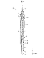
図2は、図1に示すヒータを中心としたグロープラグの部分拡大断面図である。なお、図2において図1と同じ構成部には、同じ符号を付してその説明を省略する。ヒータ4は、基体21及び導電部22を備えている。基体21は、絶縁性セラミックにより形成されている。基体21は、軸線C1に沿って延設して先端が曲面である略円柱状の外観形状を有する。基体21の内部には、導電部22が埋設されている。
FIG. 2 is a partially enlarged sectional view of the glow plug with the heater shown in FIG. 1 as the center. In FIG. 2, the same components as those in FIG. The heater 4 includes a
導電部22は、2つの延設部31,32と、連結部33と、2つの電極部27,28とを備えている。2つの延設部31,32は、それぞれ導電性セラミックからなる棒状の部材であり、基体21内部に配置されている。2つの延設部31,32は、互いに長手方向が平行となるように、また、それぞれの軸線(軸線)C11,C12がグロープラグ100の軸線C1と平行となるように配置されている。また、2つの延設部31,32は、3つの軸線C1,C11,C12が、1つの仮想平面上に位置するように配置されている。
The
延設部31は、先端側に位置する先端側部位311と、後端側に位置して先端側部位311に連なる後端側部位312とからなる。先端側部位311の直径は、後端側部位312の直径よりも小さい。後端側部位312の後端寄りの位置には、電極部27が配置されている。電極部27は、後端側部位312と一体形成され、外周方向(Y軸方向)に突出して形成されている。電極部27において、後端側部位312に連なる側とは反対側の端部は、基体21の表面に露出して電極リング18の内周面に接している。このようにして、電極リング18と延設部31とが電気的に接続される。
The extending
他方の延設部32も、延設部31と同様な構成を有する。すなわち、延設部32は、先端側部位321と後端側部位322とからなり、後端側部位322の後端寄りの位置に、電極部28を備える。電極部28において、後端側部位322に連なる側とは反対側の端部は、基体21の表面に露出して外筒7の内周面に接している。このようにして、外筒7と延設部32とが電気的に接続される。
The
連結部33は、略Y軸方向に延設し、先端側部位311の先端および先端側部位321の先端に、それぞれ連なる。連結部33の直径は、先端側部位311の直径および先端側部位321の直径と略等しい。
The connecting portion 33 extends substantially in the Y-axis direction, and is connected to the distal end of the distal
上述の延設部31、延設部32、および連結部33からなる導電部22の構成は、以下のように言い換えることができる。すなわち、導電部22は、2つの後端側部位312,322からなる直径の比較的大きな2つのリード部312,322と、2つの先端側部位311,321および連結部33からなる直径が比較的小さな発熱部35とを備える。以降では、2つのリード部を、2つの後端側部位312,322の符号を用いて、2つのリード部312,322とも呼ぶ。
The configuration of the
2つのリード部312,322は、いずれも発熱部35に連なり、発熱部35に電流を導く。上述のように発熱部35の直径は、2つのリード部312,322の直径に比べて小さいため発熱し易く、例えば、1000℃以上まで昇温する。ヒータ4は、ピン端子8、中軸3、および電極リング18を介して供給される電流を、電極部27、リード部312を介して発熱部35に導き、リード部322、電極部28を介して外筒7、主体金具2へ流すことで、発熱部35が発熱して昇温する。発熱部35は、使用時において、例えば1000℃以上の温度まで昇温する。
The two
後述するように、ヒータ4の製造の際に用いられる、基体21の基材であるセラミック材料には、希土類元素が含まれている。そのため、完成品の基体21にも希土類元素が含まれている。本実施形態のヒータ4では、ヒータ4の中心部の基体21における希土類元素の含有率と、ヒータ4の表層部の基体21における希土類元素の含有率とは、互いに異なる。以下、その含有率について、図3を用いて説明する。
As will be described later, the ceramic material which is the base material of the base 21 used in manufacturing the heater 4 contains a rare earth element. Therefore, the
図3は、ヒータ4の断面図である。図3では、図2におけるA−A断面を示す。A−A断面は、軸線C1と垂直な断面であり、発熱部35を含む断面である。ヒータ4の断面の外形形状は、略円形である。本実施形態において、ヒータ4の直径は、およそ3mm(ミリメートル)である。
FIG. 3 is a cross-sectional view of the heater 4. In FIG. 3, the AA cross section in FIG. 2 is shown. The AA cross section is a cross section that is perpendicular to the axis C <b> 1 and includes the
図3に示す断面には、発熱部35のうち、2つの先端側部位311,321が現れている。これら2つの先端側部位311,321は、ヒータ4の重心p2を挟んで互いに点対称の関係となるように配置されている。
In the cross section shown in FIG. 3, two
本実施形態のヒータ4では、ヒータ4の中心部Saの基体21における希土類元素の含有率αaは、ヒータ4の表層部Sbの基体21における希土類元素の含有率αbよりも高い。また、本実施形態において、含有率αaは、0.6atm%(原子基準濃度)以上2.0atm%以下である。なお、上記2つの含有率αb,αaは、下記式(1)に示す関係が成り立ってもよい。
0.65≦αb/αa≦0.9 ・・・(1)
In the heater 4 of this embodiment, the rare earth element content αa in the
0.65 ≦ αb / αa ≦ 0.9 (1)
また、本実施形態において、含有率αbは、0.5atm%以上1.4atm%以下であることが好ましい。含有率αbが0.5atm%以上1.4atm%以下であることで、低温環境下における耐酸化性を向上できる。さらには、含有率αbは、0.5atm%以上1.05atm%以下であることが好ましい。 In the present embodiment, the content αb is preferably 0.5 atm% or more and 1.4 atm% or less. When the content αb is 0.5 atm% or more and 1.4 atm% or less, the oxidation resistance in a low temperature environment can be improved. Furthermore, the content rate αb is preferably 0.5 atm% or more and 1.05 atm% or less.
本実施形態において、ヒータ4の中心部Saおよびヒータ4の表層部Sbとは、それぞれ図3に示す、第1領域SA内に設けられる領域Ar2および第2領域SB内に設けられる領域Ar1を意味する。領域Ar1と領域Ar2とは、いずれも円形の領域であり、互いに面積が等しい。第1領域SAは、基体21において延設部31の先端側部位311と延設部32の先端側部位321との間に位置する部位を示す。第2領域SBは、基体21において第1領域SAを除いた部位を示す。上述の領域Ar1は、自身の全範囲が第2領域SBに含まれればよく、図3に示す位置に限定されない。同様に、上述の領域Ar2は、自身の全範囲が第1領域SAに含まれればよく、図3に示す位置に限定されない。また、2つの領域Ar1,Ar2は、互いに面積が等しければ、その形状は円形に限定されるものではなく、例えば、矩形等の任意の形状であってもよい。2つの領域Ar1,Ar2の面積は、それぞれ100μm2(平方マイクロメートル)以上であることが好ましい。
In the present embodiment, the central portion Sa of the heater 4 and the surface layer portion Sb of the heater 4 mean the region Ar2 provided in the first region SA and the region Ar1 provided in the second region SB, respectively, as shown in FIG. To do. The region Ar1 and the region Ar2 are both circular regions and have the same area. The first region SA indicates a portion of the base 21 that is located between the distal
本実施形態では、ヒータ4の中心部Sa(領域Ar2)は、第1領域SAのうち、ヒータ4の重心p2を中心とした所定長さr1(25μm(マイクロメートル))を半径とする円形の領域である。また、本実施形態では、ヒータ4の表層部Sb(領域Ar1)は、第2領域SBのうち、ヒータ4の外周表面Sf1から所定の距離d1だけ内側に位置する点p1を中心とした所定長さr1を半径とする円形の領域である。本実施形態において、所定の距離d1は、100μmである。 In the present embodiment, the central portion Sa (region Ar2) of the heater 4 has a circular shape having a radius of a predetermined length r1 (25 μm (micrometer)) centered on the center of gravity p2 of the heater 4 in the first region SA. It is an area. In the present embodiment, the surface layer portion Sb (region Ar1) of the heater 4 has a predetermined length centered on a point p1 located on the inner side from the outer peripheral surface Sf1 of the heater 4 by a predetermined distance d1 in the second region SB. This is a circular region having a radius of r1. In the present embodiment, the predetermined distance d1 is 100 μm.
また、本実施形態において、基体21に含まれる希土類元素は、エルビウム(Er)、ツリウム(Tm)、イッテルビウム(Yb)、ルテチウム(Lu)から選ばれる少なくとも1種である。なお、これらの元素のうち、製造コストや安定的に入手できるという観点から、エルビウム(Er)およびイッテルビウム(Yb)が好ましい。更に、耐酸化性の観点からイッテルビウム(Yb)が更に好ましい。
In the present embodiment, the rare earth element contained in the
以下、上記構成を有するグロープラグ100の製造方法について、図4〜6を用いて説明する。
Hereinafter, a method for manufacturing the
A2.グロープラグ100の製造方法:
図4は、グロープラグ100の製造手順を示す工程表である。まず、導電部22の成形材料が作製され(工程P105)、基体21の成形材料が作製される(工程P110)。なお、これら2つの工程P105,P110は、この順序とは逆の順序で実行されてもよい。また、これら2つの工程P105,P110は、同時に実行されてもよい。本実施形態において、導電部22の成形材料は、セラミック(主に、窒化珪素、タングステンカーバイド、焼結助剤)を主成分とするペレットであり、例えば、セラミックとバインダ等を、ニーダーを用いて混練し、その後ペレット化して作製することができる。また、本実施形態では、バインダは、特に限定されるものではなく、例えば、ポリプロピレン等の可塑性樹脂、ワックス、分散剤及び可塑剤等を、1種又は2種以上を混合して用いることができる。本実施形態において、焼結助剤は、上述した希土類元素、すなわち、エルビウム(Er)、ツリウム(Tm)、イッテルビウム(Yb)、ルテチウム(Lu)から選ばれる希土類酸化物の少なくとも1種を含む。なお、焼結助剤は、希土類酸化物の他、アルミナ、窒化アルミニウム(AlN)、酸化モリブデン(MoO3)、酸化タングステン(WO3)シリカ(SiO2)等を含んでも良い。
A2. Manufacturing method of glow plug 100:
FIG. 4 is a process chart showing the manufacturing procedure of the
本実施態様において、基体21の成形材料は、セラミック(主に、窒化珪素および焼結助剤)を主成分とするペレットであり、例えば、セラミックとバインダ等を、ニーダー(混練機)を用いて混練し、その後ペレット化して作製することができる。バインダおよび焼結助剤は、上述した導電部22の焼結助剤と同様である。ここで、ステップP110における焼結助剤中の希土類元素の量は、ヒータ4が完成した段階で、ヒータ4の中心部の基体21における希土類元素の含有率が0.6atm%以上となるような含有率に調整されている。このような量は、例えば、実験により求めて設定することができる。
In this embodiment, the molding material of the
導電部の中間成形体200を、工程P105で得られた成形材料を用いて射出成形にて作製する(工程P115)。本実施形態において、「導電部の中間成形体200」とは、後述する脱脂および焼成工程を経て導電部22となる部材を意味する。なお、射出成形に代えて、粉末プレス成形、および鋳込み成形等の任意の成形方法により、導電部の中間成形体200を作製してもよい。
The intermediate molded
工程P115で得られた導電部の中間成形体200の片面側に、半割り状の基体21の中間成形体を成形する(工程P120)。導電部の中間成形体200の他方の面側に、基体21の中間成形体の残部を形成して、ヒータ4の中間成形体を得る(工程P125)。工程P120,P125では、いずれも工程P110で得られた成形材料を用いた射出成形により実行される。なお、射出成形に代えて、粉末プレス成形、および鋳込み成形等の任意の成形方法により作製してもよい。
An intermediate formed body of the half-shaped
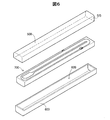
図5は、工程P120の処理内容を模式的に示す説明図である。図6は、工程P125の処理内容を模式的に示す説明図である。図5に示すように、工程P120では、まず、導電部の中間成形体200を下金型400に形成されたキャビティ420内に配置し、導電部の中間成形体200の上半分を覆うように上金型500を配置する。導電部22の中間成形体200は、導電部22とほぼ相似形の外観形状を有する。すなわち、導電部の中間成形体200は、リード部312に対応するリード対応部212と、リード部322に対応するリード対応部222と、発熱部35に対応する発熱対応部235と、2つの電極部27,28に対応する2つの電極対応部227,228とを備えている。2つのリード対応部212,222は、後述する脱脂、焼成、研磨および切断等の工程を経て2つのリード部312,322となる。同様に、発熱対応部235および2つの電極対応部227,228は、それぞれ、後述する脱脂、焼成、研磨および切断等の工程を経て、発熱部35および2つの電極部27,28になる。また、導電部の中間成形体200は、後端連結部250を備えている。後端連結部250は、導電部の中間成形体200において、発熱対応部335とは反対側において、2つのリード対応部212,222の端部同士を連結する。後端連結部250は、2つのリード対応部212,222の相対的な位置がずれることを抑制して、中間成形体200の取扱いを容易にするために設けられている。
FIG. 5 is an explanatory diagram schematically showing the processing content of the process P120. FIG. 6 is an explanatory diagram schematically showing the processing content of the process P125. As shown in FIG. 5, in the process P120, first, the intermediate molded
下金型400に形成されたキャビティ420は、導電部22の中間成形体200の下半分が収容可能な形状に形成されている。上金型500は、下金型400との合わせ面側が開口した中空の直方体状の外観形状を有する。上金型500の長手方向の一方の端面Sf5には、成形材料を上金型500の内部に充填するための射出孔が設けられている。上述のように導電部の中間成形体200、下金型400、および上金型500を配置した後、上金型500内に工程P110で得られた成形材料を射出して、半割り状の基体21の中間成形体を、導電部の中間成形体200の片側面側(図5における上方面側)に成形する。このようにして、図6に示す中間成形体700が得られる。
The
工程P125では、工程P120で得られた中間成形体700を、上下反転させて図6に示す姿勢として新たな下金型600のキャビティ620内に配置する。次に、中間成形体700の上半分を覆うように上金型500を配置する。下金型600に形成されたキャビティ620は、中間成形体700における半割り状の基体21の中間成形体の部分がちょうど収容可能な形状に形成されている。この上金型500は、図5に示す上金型500と同じである。上述のように中間成形体700、下金型600、および上金型500を配置した後、上金型500内に工程P110で得られた成形材料を射出して、中間成形体700の上半分に基体21の中間成形体の残部を形成する。このようにして、ヒータ4の中間成形体が得られる。本実施形態において、「ヒータ4の中間成形体」とは、後述する脱脂、焼成、研磨および切断等の工程を経てヒータ4となる部材を意味する。
In Step P125, the intermediate molded
図4に示すように、工程P125においてヒータ4の中間成形体が得られると、ヒータ4の中間成形体の脱脂が実行される(工程P130)。ヒータ4の中間成形体には、バインダが含まれているので、加熱(仮焼成)することにより、かかるバインダが取り除かれる。例えば、ヒータ4の中間形成体を、窒素雰囲気中にて800℃で60分加熱してもよい。工程P130の後、本焼成が実行される(工程P135)。かかる本焼成では、工程P130のいわゆる仮焼成に比べて、高温で加熱が行なわれる。例えば、最高1850℃程度まで昇温されるように加熱される。また、本焼成では、1気圧以下で焼成を行うとともに、1気圧以上7気圧以下の窒素雰囲気下で焼成を行なってもよい。 As shown in FIG. 4, when the intermediate molded body of the heater 4 is obtained in the process P125, the intermediate molded body of the heater 4 is degreased (process P130). Since the intermediate molded body of the heater 4 contains a binder, the binder is removed by heating (preliminary firing). For example, the intermediate formed body of the heater 4 may be heated at 800 ° C. for 60 minutes in a nitrogen atmosphere. After the step P130, main firing is performed (step P135). In the main baking, the heating is performed at a higher temperature than the so-called temporary baking in the process P130. For example, heating is performed so that the temperature is raised to about 1850 ° C. at the maximum. Further, in the main firing, the firing may be performed at 1 atm or less and in a nitrogen atmosphere at 1 atm or more and 7 atm or less.
ここで、本実施形態では、この本焼成(工程P135)においてヒータ4(ヒータ4の中間成形体)の表層部Sbから希土類元素を揮発させることにより、中心部Saにおける希土類元素の含有率αaが表層部Sbにおける希土類元素の含有率αbよりも高くなるように調整している。このように中心部Saにおける含有率αaが表層部Sbにおける含有率αbよりも高くなるように表層部Sbから希土類元素を揮発させるための焼成条件は、実験により求めることができる。例えば、最高温度、その最高温度を維持する時間、窒素ガスを導入した後における最高温度に達した際の炉内圧力、その窒素ガスの導入温度の維持時間などの焼成条件を適宜調整してヒータ4を作製し、かかるヒータ4の表層部Sbおよび中心部Saの希土類元素の含有率を測定する。このようにして、焼成条件の調整および希土類元素の含有率の測定を繰り返し実行して、上記式(1)を満たす焼成条件を特定することができる。 Here, in the present embodiment, the rare earth element content αa in the central portion Sa is obtained by volatilizing the rare earth element from the surface layer portion Sb of the heater 4 (intermediate molded body of the heater 4) in the main firing (process P135). It is adjusted to be higher than the rare earth element content αb in the surface layer portion Sb. Thus, the firing conditions for volatilizing the rare earth element from the surface layer portion Sb so that the content rate αa in the center portion Sa is higher than the content rate αb in the surface layer portion Sb can be obtained by experiments. For example, the heater is adjusted by appropriately adjusting the firing conditions such as the maximum temperature, the time for maintaining the maximum temperature, the pressure in the furnace when the maximum temperature is reached after nitrogen gas is introduced, and the time for maintaining the nitrogen gas introduction temperature. 4 is measured, and the content of rare earth elements in the surface layer portion Sb and the central portion Sa of the heater 4 is measured. In this way, the adjustment of the firing conditions and the measurement of the rare earth element content can be repeatedly performed to identify the firing conditions that satisfy the above formula (1).
本焼成の後、研磨加工及び切断加工が実行される(工程P140)。研磨加工により、電極部27,28が基体21の表面から露出する。また、切断加工により、工程P135により得られた焼成体の後端部、すなわち、後端連結部250に相当する部分が取り除かれる。上述した工程P105〜P140により、ヒータ4が完成する。その後、図1に示すグロープラグ100の各構成部が組みつけられ(工程P145)、グロープラグ100が完成する。なお、主体金具2等の各構成部の製造方法としては、公知の方法を採用できる。上述の工程P105〜P140は、ヒータ4の製造方法に相当する。
After the main firing, polishing and cutting are performed (process P140). The
以上説明した本実施形態のヒータ4によれば、ヒータ4の中心部Saの基体21における希土類元素の含有率αaは、ヒータ4の表層部Sbの基体21における希土類元素の含有率αbに比べて高い。加えて、ヒータ4の中心部Saの基体21における希土類元素の含有率αaは0.6atm%以上である。そのため、焼成時に十分な液相を供給でき、ヒータ4の中心部Saの基体21における焼結性を向上できる。また、ヒータ4の中心部Saの基体21における希土類元素の含有率αaは2.0atm%以下であるので、低温環境下における基体21の耐酸化性の低下を抑制できる。他方、表層部Sbの基体21における希土類元素の含有率αbは相対的に低いので、低温環境下における表層部Sbの耐酸化性の低下を抑制できる。基体21における表層部Sbの耐酸化性は基体21全体の耐酸化性に大きな影響を与えるため、本実施形態のヒータ4によれば、基体21全体の耐酸化性を向上できる。したがって、上記実施形態のヒータ4によれば、基体21の耐酸化性の向上と焼結性の向上とを両立できる。また、焼結助剤に用いられる希土類元素として、エルビウム(Er)、ツリウム(Tm)、イッテルビウム(Yb)、ルテチウム(Lu)から選ばれる少なくとも1種であるので、粒界相の結晶化を促進して、高温環境下での耐酸化性を向上できる。
According to the heater 4 of the present embodiment described above, the rare earth element content αa in the
B.実施例:
上述した実施形態のヒータ4と同一または同様なヒータを試料として作製し、これら試料について、耐酸化性試験および焼結性試験を行なった。耐酸化性試験では、1300℃(高温環境)での耐酸化性と、800℃(低温環境)での耐酸化性とを評価した。下記表1は、耐酸化性試験および焼結性試験の試験結果を示す。なお、表1では、耐酸化性および焼結性試験の結果(評価結果)に加えて、各試料についての希土類種別と、中心部Saの希土類元素の含有率αaと、表層部Sbの希土類元素の含有率αbと、これら含有率の割合αa/αbとが記載されている。
B. Example:
The same or similar heater as the heater 4 of the above-described embodiment was produced as a sample, and an oxidation resistance test and a sinterability test were performed on these samples. In the oxidation resistance test, the oxidation resistance at 1300 ° C. (high temperature environment) and the oxidation resistance at 800 ° C. (low temperature environment) were evaluated. Table 1 below shows the test results of the oxidation resistance test and the sinterability test. In Table 1, in addition to the oxidation resistance and sinterability test results (evaluation results), the rare earth type for each sample, the rare earth element content αa in the central portion Sa, and the rare earth elements in the surface layer portion Sb Content rate αb and the ratio αa / αb of these content rates are described.

B1.1300℃耐酸化性試験:
1300℃耐酸化性試験では、まず、上述した実施形態のヒータ4と同様な9つのヒータ(試料1〜9)を作製した。なお、試料1〜9のうち、試料7における希土類元素は、エルビウム(Er)であり、他の試料1〜7,8,9における希土類元素は、イッテルビウム(Yb)であった。また、試料1〜9の焼成条件をそれぞれ異ならせることで、試料1〜9の含有率αa,αbの組み合わせを互いに異ならせた。
B1.1300 ° C. oxidation resistance test:
In the 1300 ° C. oxidation resistance test, first, nine heaters (samples 1 to 9) similar to the heater 4 of the embodiment described above were produced. Among samples 1 to 9, the rare earth element in
なお、これら9つ試料1〜9は、電極部27,28を有していない点において、上述した実施形態のヒータ4と異なる。その他の構成および製造方法は、上述した実施形態のヒータ4と同じである。電極部27,28が存在する場合、ヒータ4の外周表面Sf1に露出する電極部27,28から酸化が進んで導電部22が酸化し、基体21の耐酸化性を正確に特定できない。このため、試料1〜9を、電極部27,28を省略して作製した。次に、作製した試料1〜9の重量および表面積を測定した。次に、試料1〜9を、所定の温度で所定期間加熱した。具体的には、1300℃で50時間加熱した。その後、加熱後の試料1〜9の重量を測定した。そして、加熱前後における単位面積当たりの重量の変化量に応じて耐酸化性を評価した。具体的には、単位面積当たりの重量の変化量が少ないほど耐酸化性が高いと評価し、変化量が多いほど耐酸化性が低いと評価した。窒化珪素の酸化が進むと基体21における単位面積当たりの重量は増加する。したがって、加熱前後における重量の変化が多いということは、窒化珪素の酸化がより進んでいることを意味し、それは、基体の耐酸化性が低いことを示す。上記表1では、単位面積当たりの重量の変化が0.20g/cm2以下である場合に、「○(最も高い)」と評価し、0.20g/cm2よりも大きく0.28g/cm2以下である場合に、「△(2番目に高い)」と評価し、0.28g/cm2よりも大きい場合に、「×(最も低い)」と評価した。
In addition, these nine samples 1-9 differ from the heater 4 of embodiment mentioned above in the point which does not have the
また、比較例としてのヒータ4を3種類(試料10〜12)作製し、これら試料10〜12についても耐酸化性試験および焼結性試験を実行し、各性能について評価した。比較例の試料10は、中心部Saの希土類元素の含有率αaが0.6atm%以上ではない点において、上述した実施形態のヒータ4と異なる。比較例の試料11は、中心部Saの希土類元素の含有率αaが2.0atm%以下ではない点において、上述した実施形態のヒータ4と異なる。比較例の試料12は、中心部Saの希土類元素の含有率αaが、表層部Sbの希土類元素の含有率αbよりも低い点において、上述した実施形態のヒータ4と異なる。
In addition, three types of heaters 4 (
1300℃耐酸化性試験の評価結果では、試料1〜9のうち、試料7,8を除く他の試料1〜6,9において、最も高い「○」の評価となった。また、試料7,8については、2番目に高い「△」であった。このように試料1〜9について比較的高い評価となったのは、ヒータ4の中心部Saの基体21における希土類元素の含有率αaが0.6atm%以上であったためである。なお、比較例の試料11,12についても、中心部Saの含有率αaが0.6atm%以上であるため耐酸化性評価は「○」であったものと推測される。これに対して、比較例の試料10については、中心部Saの含有率αaが0.6atm%未満である。したがって、中心部Saの希土類元素(Yb)が少量であるため、高温環境下での耐酸化性評価が「×」になったものと推測される。
In the evaluation results of the 1300 ° C. oxidation resistance test, among the samples 1 to 9, the other samples 1 to 6 and 9 other than the
ここで、試料3と試料7とに着目すると、2つの試料は、希土類種別において異なり、含有率αa,αbは、互いに等しい。耐酸化性の評価結果は、試料3が「○」であるのに対して、試料6が「△」であった。かかる評価結果から、焼結助剤に含有する希土類元素としては、エルビウム(Er)よりもイッテルビウム(Yb)が、高温環境下での耐酸化性の観点で好ましいことが理解できる。
Here, paying attention to
なお、各試料1〜12の中心部Saの希土類元素の含有率αaと、表層部Sbの希土類元素の含有率αbとは、以下のように測定した。すなわち、各試料を作成する際の焼成条件をそれぞれ同じにした12種類のヒータを、各試料1〜12とは別に作製し、これら12種類の試料を、それぞれ発熱部35において軸線C1と垂直に切断し、現れた断面における中心部Saおよび表層部Sbについて、それぞれ電子線マイクロアナライザ(EPMA)を用いて希土類元素の含有率を測定した。なお、EPMAに代えて、エネルギー分散型X線分析(EDS)により希土類元素の含有率を測定してもよい。
The rare earth element content αa in the central portion Sa and the rare earth element content αb in the surface layer portion Sb of each sample 1 to 12 were measured as follows. That is, twelve types of heaters having the same firing conditions at the time of preparing each sample are prepared separately from each sample 1 to 12, and these twelve types of samples are respectively perpendicular to the axis C1 in the
B2.800℃耐酸化性試験:
800℃耐酸化性試験では、上記1300℃耐酸化性試験に用いた試料1〜12と同様な12種類(12個)のヒータ(試料1〜12)を作製した。次に、試料1〜12を、所定の温度で所定期間加熱した。具体的には、800℃で50時間加熱した。その後、加熱後の試料1〜12の断面を観察し、耐酸化性を評価した。具体的には、表面からの酸化の進行が少ないほど耐酸化性が高いと評価し、酸化の進行が多いほど耐酸化性が低いと評価した。上記表1では、酸化の進行が表面から20μm未満である場合に「◎(最も高い)」と評価し、酸化の進行が表面から20μm以上30μm未満である場合に「○(2番目に高い)」と評価し、酸化の試行が表面から30μm以上50μm未満である場合に「△(3番目に高い)」と評価し、酸化の進行が表面から50μm以上である場合に、「×(最も低い)」と評価した。
B2.800 ° C. oxidation resistance test:
In the 800 ° C. oxidation resistance test, 12 types (12 pieces) of heaters (samples 1 to 12) similar to the samples 1 to 12 used in the 1300 ° C. oxidation resistance test were prepared. Next, samples 1 to 12 were heated at a predetermined temperature for a predetermined period. Specifically, it was heated at 800 ° C. for 50 hours. Then, the cross section of the samples 1-12 after a heating was observed and oxidation resistance was evaluated. Specifically, the smaller the progress of oxidation from the surface, the higher the oxidation resistance, and the higher the progress of oxidation, the lower the oxidation resistance. In Table 1 above, when the progress of oxidation was less than 20 μm from the surface, it was evaluated as “◎ (highest)”, and when the progress of oxidation was 20 μm or more and less than 30 μm from the surface, “◯ (second highest)” ”And evaluated as“ △ (third highest) ”when the oxidation trial is 30 μm or more and less than 50 μm from the surface, and“ × (lowest) when the progress of oxidation is 50 μm or more from the surface ) ”.
800℃耐酸化性試験の評価結果では、試料1〜9のうち、試料1〜4,6〜8において、最も高い「◎」の評価となった。また、試料5については、2番目に高い「○」であった。また、試料9については、3番目に高い「△」であった。このように試料1〜9について比較的高い評価となったのは、表層部Sbの基体21における希土類元素の含有率αbを相対的に低減させ、低温環境下での耐酸化性の低下を抑制できたためであると推測される。なお、比較例の試料10についても、中心部Saの含有率αaが表層部Sbの含有率αbよりも高いので、上記と同じ理由により、耐酸化性評価は「○」であったものと推測される。これに対して、比較例の試料12については、中心部Saの含有率αaが表層部Sbの含有率αbよりも低い。したがって、表層部Sbに希土類元素(Yb)が多量に存在するために、比較的低い温度環境下において表層部Sbの酸化が進み、耐酸化性評価が「×」になったものと推測される。
In the evaluation results of the 800 ° C. oxidation resistance test, among samples 1 to 9, samples 1 to 4 and 6 to 8 had the highest “◎” evaluation. Sample 5 was the second highest “◯”.
また、比較例の試料11については、中心部Saの含有率αaが表層部Sbの含有率αbよりも高いものの、中心部Saの含有率αaが2.0atm%を超えている。したがって、中心部Saに希土類元素(Yb)が多量に存在するために、比較的低い温度環境下において酸化が進み、耐酸化性評価が「×」になったものと推測される。
Moreover, about the
ここで、試料1〜6に着目すると、表層部Sbの含有率αbが1.05atm%以下の試料1〜4,6は、耐酸化性評価が「◎」であるのに対して、表層部Sbの含有率αbが1.3の試料5は、耐酸化性試験が「○」であった。かかる評価結果から、表層部Sbの含有率αbは、0.5atm%以上1.05atm%以下であることが好ましい。 Here, focusing on the samples 1 to 6, the samples 1 to 4 and 6 in which the content αb of the surface layer portion Sb is 1.05 atm% or less have an oxidation resistance evaluation of “◎”, whereas the surface layer portion Sample 5 in which the Sb content αb was 1.3 had an oxidation resistance test of “◯”. From the evaluation results, the content αb of the surface layer portion Sb is preferably 0.5 atm% or more and 1.05 atm% or less.
B3.焼結性試験:
焼結性試験では、まず、上述した実施形態のヒータ4の製造方法に従って9つのヒータを作製した。また、上述の耐酸化性試験の比較例と同様な3つのヒータを作製した。これら合計12個のヒータは、電極部27,28を含んでいる点において、上述した耐酸化性試験の12個の試料1〜12と異なり、その他の構成、および焼成条件を含む製造方法は、上述した試料1〜12と同じである。なお、上述のように、中心部Saの含有率αaが表層部Sbの含有率αbよりも高くなるように調整するためには、焼成条件の調整が重要なポイントとなり、導電部22を含むか否かは大きな影響を与えない。そこで、焼結性試験において、上述の試料1〜12に対応する試料についても、試料1〜12と呼ぶものとする。次に、12個の試料1〜12について、相対密度を測定した。本実施例では、アルキメデス法により密度測定を行い、かかる測定値と理論密度値とから相対密度を求めた。そして、相対密度が高いほど焼結性が高いと判断した。相対密度が高いほど、粒界部分に生じる空孔が少ないことが推測され、したがって焼結性(焼き締められた状態となる性質)が高いと評価できる。なお、本実施例では、本焼成における最高焼成温度は1850℃以下であり、そのときの炉内の圧力は7atm以下であるものとした。上記表1では、相対密度が98%以上である場合に「○(最も高い)」と評価し、97%以上98%未満である場合に「△(2番目に高い)」と評価し、97%未満である場合に「×(最も低い)」と評価した。
B3. Sinterability test:
In the sinterability test, nine heaters were first manufactured according to the method for manufacturing the heater 4 of the above-described embodiment. In addition, three heaters similar to the comparative example of the oxidation resistance test described above were produced. These 12 heaters are different from the 12 samples 1 to 12 in the oxidation resistance test described above in that the
焼結性試験の評価結果では、試料1〜12のうち、試料8,10を除く他の試料1〜7,9,11,12において、最も高い「○」の評価となった。また、試料8については、2番目に高い「△」であった。このように試料1〜9について比較的高い評価となったのは、中心部Saにおける希土類元素の含有率αaがいずれも0.6atm%以上と比較的高いためであると推測される。比較例の試料11,12についても、中心部Saにおける希土類元素の含有率αaが0.6atm%以上と比較的高いために、焼結性評価は「○」であったものと推測される。これに対して、比較例の試料10については、中心部Saにおける希土類元素の含有率αaが0.50atm%と比較的低いために、焼結性評価が「×」になったものと推測される。
In the evaluation results of the sinterability test, among the samples 1 to 12, the other samples 1 to 7, 9, 11, and 12 other than the
ここで、試料8の含有率の比(αb/αa)は、60.0%であり、他の試料1〜6の含有率の比に比べて小さい。含有率の比が60.0%と比較的低い場合、焼結時に液相量が不足するために粒界部分に微細な空孔が生じ、焼結性が低下するものと推測される。このような、試料1〜6と、試料7,8との比較からも理解できるように、2つの含有率の比(αb/αa)が上記式(1)を満たすことで、焼結性を向上させることができる。
Here, the content ratio (αb / αa) of the sample 8 is 60.0%, which is smaller than the content ratios of the other samples 1 to 6. When the content ratio is relatively low at 60.0%, the liquid phase amount is insufficient at the time of sintering, so fine pores are generated in the grain boundary portion, and it is assumed that the sinterability is lowered. As can be understood from the comparison between Samples 1 to 6 and
C.変形例:
C1.変形例1:
上記実施形態および実施例において、2つの含有率αa,αbを規定する際の中心部Saおよび表層部Sbは、発熱部35のうち、2つの先端側部位311,321が現れる断面における中心部Saおよび表層部Sbであったが、本発明はこれに限定されない。2つの先端側部位311,321に代えて、2つの後端側部位312,322が現れる断面における中心部および表層部であってもよい。すなわち、一般には、2つの延設部31,32が現れる断面における中心部Saおよび表層部Sbにより、2つの含有率αa,αbを規定してもよい。
C. Variations:
C1. Modification 1:
In the above-described embodiment and examples, the central portion Sa and the surface layer portion Sb when defining the two content ratios αa and αb are the central portion Sa in the cross section in which the two
C2.変形例2:
上記実施形態および実施例において、各延設部31,32は、それぞれ単一の部材(中間成形体)から形成されていたが、本発明はこれに限定されない。各延設部を複数種類の部材により構成してもよい。例えば、延設部31において、先端側部位311に相当する部材と、後端側部位312に相当する部材とを、互いに異なる種類の部材で構成してもよい。この構成では、例えば、先端側部位311に相当する部材におけるタングステンカーバイドの含有率を、後端側部位312に相当する部材におけるタングステンカーバイドの含有率よりも低くして、先端側部位311の比抵抗をより大きくして発熱し易くすることもできる。かかかる構成においては、先端側部位311に相当する部材と後端側部位312に相当する部材との境界から連結部33までの間は、請求項における先端側部位の下位概念に相当する。
C2. Modification 2:
In the said embodiment and Example, each
C3.変形例3:
上記実施形態および実施例において、ヒータ4の中心部Saは、ヒータ4の重心p2を中心とした所定長さr1を半径とする円形の領域Ar2であったが、本発明はこれに限定されない。ヒータ4の重心を中心とする矩形などの任意の形状の領域であってもよい。また、ヒータ4の重心を中心としない、第1領域SA内の任意の位置の領域であってもよい。
C3. Modification 3:
In the above-described embodiment and examples, the center portion Sa of the heater 4 is the circular region Ar2 having a radius of the predetermined length r1 centered on the center of gravity p2 of the heater 4, but the present invention is not limited to this. An area having an arbitrary shape such as a rectangle centered on the center of gravity of the heater 4 may be used. Moreover, the area | region of the arbitrary positions in 1st area | region SA which does not center on the gravity center of the heater 4 may be sufficient.
また、上記実施形態および実施例において、ヒータ4の表層部Sbは、ヒータ4の外周表面Sf1から所定の距離d1だけ内側に位置する点p1を中心とした所定長さr1を半径とする円形の領域Ar1であったが、本発明はこれに限定されない。外周表面Sf1から所定の距離だけ内側に入った点の集合である円周と、外周表面Sf1との間の領域であってもよい。また、外周表面Sf1を含んだ領域としてもよい。さらには、第2領域SB内の任意の位置の領域であってもよい。 Further, in the above-described embodiments and examples, the surface layer portion Sb of the heater 4 has a circular shape with a predetermined length r1 centered on a point p1 located at a predetermined distance d1 from the outer peripheral surface Sf1 of the heater 4 as a radius. Although the region is Ar1, the present invention is not limited to this. It may be a region between a circumference that is a set of points that enter a predetermined distance from the outer peripheral surface Sf1 and the outer peripheral surface Sf1. Moreover, it is good also as an area | region including outer peripheral surface Sf1. Furthermore, the area | region of the arbitrary positions in 2nd area | region SB may be sufficient.
C4.変形例4:
上記実施形態および実施例では、導電部22の成形材料における導電性材料は、タングステンカーバイドであったが、これに代えて、珪化モリブデンや珪化タングステン等の、任意の導電性材料を用いることができる。
C4. Modification 4:
In the above-described embodiment and examples, the conductive material in the molding material of the
C5.変形例5:
上記実施形態では、ヒータ4は、グロープラグ100に用いられるセラミックヒータであったが、グロープラグ100に代えて、バーナーの着火用のヒータ、ガスセンサの加熱用ヒータ、DPF(Diesel particulate filter)に使用されるセラミックヒータであってもよい。
C5. Modification 5:
In the above embodiment, the heater 4 is a ceramic heater used for the
本発明は、上述の実施形態、実施例および変形例に限られるものではなく、その趣旨を逸脱しない範囲において種々の構成で実現することができる。例えば、発明の概要の欄に記載した各形態中の技術的特徴に対応する本実施形態、変形例中の技術的特徴は、上述の課題の一部又は全部を解決するために、あるいは、上述の効果の一部又は全部を達成するために、適宜、差し替えや、組み合わせを行うことが可能である。また、その技術的特徴が本明細書中に必須なものとして説明されていなければ、適宜、削除することが可能である。 The present invention is not limited to the above-described embodiments, examples, and modifications, and can be realized with various configurations without departing from the spirit of the present invention. For example, the technical features in the present embodiment and the modified examples corresponding to the technical features in the embodiments described in the column of the summary of the invention are to solve part or all of the above-described problems, or In order to achieve part or all of the above effects, replacement or combination can be appropriately performed. Further, if the technical feature is not described as essential in the present specification, it can be deleted as appropriate.
2…主体金具
3…中軸
4…ヒータ
5…絶縁部材
6…フランジ部
7…外筒
8…ピン端子
9,10…軸孔
11…雄ねじ部
12…工具係合部
15…厚肉部
16…係合部
18…電極リング
21…基体
22…導電体
27,28…電極部
31,32…延設部
33…連結部
35…発熱部
100…グロープラグ
200…中間成形体
212,222…リード対応部
227…電極対応部
235…発熱対応部
250…後端連結部
311…先端側部位
312…後端側部位(リード部)
321…先端側部位
322…後端側部位(リード部)
335…発熱対応部
400…下金型
420…キャビティ
500…上金型
600…下金型
620…キャビティ
700…中間成形体
Ar1,Ar2…領域
C1,C11,C12…軸線
Sa…中心部
Sb…表層部
Sf1…外周表面
Sf5…端面
d1…距離
p1…点
p2…重心
DESCRIPTION OF
321 ... Front
335 ... Heat
Claims (7)
前記軸線方向と直交し前記2つの延設部が現われる断面において、前記セラミックヒータの中心部の前記基体における前記希土類元素の含有率は、前記セラミックヒータの表層部の前記基体における前記希土類元素の含有率に比べて高く、
前記中心部の前記基体における前記希土類元素の含有率は、0.6atm%以上2.0atm%以下である、
ことを特徴とする、セラミックヒータ。 A base body containing silicon nitride as a main component and further containing a rare earth element and extending in the axial direction; two extending portions embedded in the base body and extending along the axial direction; and the two A ceramic heater comprising a conductive portion including a connecting portion that connects the distal end portions of the extending portion;
In the cross section perpendicular to the axial direction and where the two extending portions appear, the content of the rare earth element in the substrate at the center of the ceramic heater is the content of the rare earth element in the substrate at the surface layer of the ceramic heater. Higher than the rate,
The rare earth element content in the substrate in the center is 0.6 atm% or more and 2.0 atm% or less.
A ceramic heater characterized by that.
前記導電部は、各前記延設部における先端側部位と前記連結部とにより形成された発熱部と、該発熱部に連なり各前記延設部における後端側部位によりそれぞれ形成された2つのリード部と、を有し、
前記断面は、前記発熱部が現れる断面である、
ことを特徴とする、セラミックヒータ。 The ceramic heater according to claim 1,
The conductive portion includes a heat generating portion formed by a front end side portion and the connecting portion in each extending portion, and two leads formed by a rear end side portion in each extending portion connected to the heat generating portion. And
The cross section is a cross section in which the heat generating portion appears.
A ceramic heater characterized by that.
前記表層部の前記基体における前記希土類元素の含有率は、前記中心部の前記基体における前記希土類元素の含有率の65%以上90%以下である、
ことを特徴とする、セラミックヒータ。 In the ceramic heater according to claim 1 or 2,
The content of the rare earth element in the substrate of the surface layer portion is 65% or more and 90% or less of the content of the rare earth element in the substrate of the center portion.
A ceramic heater characterized by that.
前記希土類元素は、エルビウム(Er)、ツリウム(Tm)、イッテルビウム(Yb)、ルテチウム(Lu)から選ばれる少なくとも1種である、
ことを特徴とする、セラミックヒータ。 In the ceramic heater according to any one of claims 1 to 3,
The rare earth element is at least one selected from erbium (Er), thulium (Tm), ytterbium (Yb), and lutetium (Lu).
A ceramic heater characterized by that.
前記希土類元素は、イッテルビウム(Yb)である、
ことを特徴とする、セラミックヒータ。 The ceramic heater according to claim 4, wherein
The rare earth element is ytterbium (Yb).
A ceramic heater characterized by that.
前記表層部の前記基体における前記希土類元素の含有量は、0.5atm%以上1.05atm%以下である、
ことを特徴とする、セラミックヒータ。 In the ceramic heater according to any one of claims 1 to 5,
The rare earth element content in the substrate of the surface layer portion is 0.5 atm% or more and 1.05 atm% or less.
A ceramic heater characterized by that.
前記セラミックヒータが、請求項1から請求項6までのいずれか一項に記載のセラミックヒータである、
ことを特徴とする、グロープラグ。 A glow plug comprising a ceramic heater and a metal cylinder holding the ceramic heater,
The ceramic heater is the ceramic heater according to any one of claims 1 to 6,
A glow plug characterized by that.
Priority Applications (1)
| Application Number | Priority Date | Filing Date | Title |
|---|---|---|---|
| JP2016084277A JP6438909B2 (en) | 2016-04-20 | 2016-04-20 | Ceramic heater and glow plug |
Applications Claiming Priority (1)
| Application Number | Priority Date | Filing Date | Title |
|---|---|---|---|
| JP2016084277A JP6438909B2 (en) | 2016-04-20 | 2016-04-20 | Ceramic heater and glow plug |
Publications (2)
| Publication Number | Publication Date |
|---|---|
| JP2017195078A true JP2017195078A (en) | 2017-10-26 |
| JP6438909B2 JP6438909B2 (en) | 2018-12-19 |
Family
ID=60156470
Family Applications (1)
| Application Number | Title | Priority Date | Filing Date |
|---|---|---|---|
| JP2016084277A Active JP6438909B2 (en) | 2016-04-20 | 2016-04-20 | Ceramic heater and glow plug |
Country Status (1)
| Country | Link |
|---|---|
| JP (1) | JP6438909B2 (en) |
Citations (4)
| Publication number | Priority date | Publication date | Assignee | Title |
|---|---|---|---|---|
| JPH02180758A (en) * | 1988-12-28 | 1990-07-13 | Kyocera Corp | Silicon nitride-based sintered body |
| JPH0971471A (en) * | 1995-09-04 | 1997-03-18 | Toshiba Corp | Silicon nitride sintered compact and its production |
| JP2007335397A (en) * | 2006-05-18 | 2007-12-27 | Ngk Spark Plug Co Ltd | Ceramic heater and glow plug |
| JP2008293804A (en) * | 2007-05-24 | 2008-12-04 | Ngk Spark Plug Co Ltd | Ceramic heater and glow plug |
-
2016
- 2016-04-20 JP JP2016084277A patent/JP6438909B2/en active Active
Patent Citations (4)
| Publication number | Priority date | Publication date | Assignee | Title |
|---|---|---|---|---|
| JPH02180758A (en) * | 1988-12-28 | 1990-07-13 | Kyocera Corp | Silicon nitride-based sintered body |
| JPH0971471A (en) * | 1995-09-04 | 1997-03-18 | Toshiba Corp | Silicon nitride sintered compact and its production |
| JP2007335397A (en) * | 2006-05-18 | 2007-12-27 | Ngk Spark Plug Co Ltd | Ceramic heater and glow plug |
| JP2008293804A (en) * | 2007-05-24 | 2008-12-04 | Ngk Spark Plug Co Ltd | Ceramic heater and glow plug |
Also Published As
| Publication number | Publication date |
|---|---|
| JP6438909B2 (en) | 2018-12-19 |
Similar Documents
| Publication | Publication Date | Title |
|---|---|---|
| JP5989896B2 (en) | Ceramic heater | |
| EP1768456B1 (en) | Ceramic heater, and glow plug using the same | |
| JPWO2007013497A1 (en) | Brazing structure, ceramic heater and glow plug | |
| JP2005315447A (en) | Ceramic heater and glow plug | |
| JP6337046B2 (en) | Heater and glow plug equipped with the same | |
| JP6291542B2 (en) | Ceramic heater and glow plug | |
| JP5876566B2 (en) | Heater and glow plug equipped with the same | |
| JP6438909B2 (en) | Ceramic heater and glow plug | |
| JP5449794B2 (en) | Ceramic heater and glow plug | |
| JP2001280640A (en) | Glow plug and production method for the same | |
| JP3601079B2 (en) | Ceramic heater | |
| JP6404854B2 (en) | Ceramic sintered body, ceramic heater and glow plug | |
| EP2869666B1 (en) | Heater and glow plug equipped with same | |
| JP6370754B2 (en) | Ceramic heater and glow plug | |
| JP2019021501A (en) | Ceramic heater and glow plug | |
| JP2018010717A (en) | Ceramic heater and glow plug | |
| JP6392271B2 (en) | Ceramic sintered body, ceramic heater and glow plug | |
| JP6812146B2 (en) | Manufacturing method of ceramic heater | |
| JP6392004B2 (en) | Heater and glow plug | |
| JP2015125947A (en) | Heater and glow plug equipped with the same | |
| JP6071426B2 (en) | Manufacturing method of ceramic heater | |
| JP3903458B2 (en) | Ceramic heater and glow plug including the same |
Legal Events
| Date | Code | Title | Description |
|---|---|---|---|
| A977 | Report on retrieval |
Free format text: JAPANESE INTERMEDIATE CODE: A971007 Effective date: 20180309 |
|
| A131 | Notification of reasons for refusal |
Free format text: JAPANESE INTERMEDIATE CODE: A131 Effective date: 20180417 |
|
| A521 | Request for written amendment filed |
Free format text: JAPANESE INTERMEDIATE CODE: A523 Effective date: 20180611 |
|
| TRDD | Decision of grant or rejection written | ||
| A01 | Written decision to grant a patent or to grant a registration (utility model) |
Free format text: JAPANESE INTERMEDIATE CODE: A01 Effective date: 20181113 |
|
| A61 | First payment of annual fees (during grant procedure) |
Free format text: JAPANESE INTERMEDIATE CODE: A61 Effective date: 20181119 |
|
| R150 | Certificate of patent or registration of utility model |
Ref document number: 6438909 Country of ref document: JP Free format text: JAPANESE INTERMEDIATE CODE: R150 |
|
| R250 | Receipt of annual fees |
Free format text: JAPANESE INTERMEDIATE CODE: R250 |
|
| S531 | Written request for registration of change of domicile |
Free format text: JAPANESE INTERMEDIATE CODE: R313531 |
|
| R350 | Written notification of registration of transfer |
Free format text: JAPANESE INTERMEDIATE CODE: R350 |
|
| R250 | Receipt of annual fees |
Free format text: JAPANESE INTERMEDIATE CODE: R250 |
|
| R250 | Receipt of annual fees |
Free format text: JAPANESE INTERMEDIATE CODE: R250 |