JP2017194664A - Stand and television apparatus - Google Patents
Stand and television apparatus Download PDFInfo
- Publication number
- JP2017194664A JP2017194664A JP2017009451A JP2017009451A JP2017194664A JP 2017194664 A JP2017194664 A JP 2017194664A JP 2017009451 A JP2017009451 A JP 2017009451A JP 2017009451 A JP2017009451 A JP 2017009451A JP 2017194664 A JP2017194664 A JP 2017194664A
- Authority
- JP
- Japan
- Prior art keywords
- display device
- gear
- drive shaft
- unit
- movable gear
- Prior art date
- Legal status (The legal status is an assumption and is not a legal conclusion. Google has not performed a legal analysis and makes no representation as to the accuracy of the status listed.)
- Granted
Links
Images


Classifications
-
- F—MECHANICAL ENGINEERING; LIGHTING; HEATING; WEAPONS; BLASTING
- F16—ENGINEERING ELEMENTS AND UNITS; GENERAL MEASURES FOR PRODUCING AND MAINTAINING EFFECTIVE FUNCTIONING OF MACHINES OR INSTALLATIONS; THERMAL INSULATION IN GENERAL
- F16M—FRAMES, CASINGS OR BEDS OF ENGINES, MACHINES OR APPARATUS, NOT SPECIFIC TO ENGINES, MACHINES OR APPARATUS PROVIDED FOR ELSEWHERE; STANDS; SUPPORTS
- F16M11/00—Stands or trestles as supports for apparatus or articles placed thereon ; Stands for scientific apparatus such as gravitational force meters
- F16M11/02—Heads
- F16M11/04—Means for attachment of apparatus; Means allowing adjustment of the apparatus relatively to the stand
- F16M11/06—Means for attachment of apparatus; Means allowing adjustment of the apparatus relatively to the stand allowing pivoting
- F16M11/08—Means for attachment of apparatus; Means allowing adjustment of the apparatus relatively to the stand allowing pivoting around a vertical axis, e.g. panoramic heads
-
- F—MECHANICAL ENGINEERING; LIGHTING; HEATING; WEAPONS; BLASTING
- F16—ENGINEERING ELEMENTS AND UNITS; GENERAL MEASURES FOR PRODUCING AND MAINTAINING EFFECTIVE FUNCTIONING OF MACHINES OR INSTALLATIONS; THERMAL INSULATION IN GENERAL
- F16M—FRAMES, CASINGS OR BEDS OF ENGINES, MACHINES OR APPARATUS, NOT SPECIFIC TO ENGINES, MACHINES OR APPARATUS PROVIDED FOR ELSEWHERE; STANDS; SUPPORTS
- F16M11/00—Stands or trestles as supports for apparatus or articles placed thereon ; Stands for scientific apparatus such as gravitational force meters
- F16M11/02—Heads
- F16M11/18—Heads with mechanism for moving the apparatus relatively to the stand
-
- G—PHYSICS
- G09—EDUCATION; CRYPTOGRAPHY; DISPLAY; ADVERTISING; SEALS
- G09F—DISPLAYING; ADVERTISING; SIGNS; LABELS OR NAME-PLATES; SEALS
- G09F9/00—Indicating arrangements for variable information in which the information is built-up on a support by selection or combination of individual elements
-
- F—MECHANICAL ENGINEERING; LIGHTING; HEATING; WEAPONS; BLASTING
- F16—ENGINEERING ELEMENTS AND UNITS; GENERAL MEASURES FOR PRODUCING AND MAINTAINING EFFECTIVE FUNCTIONING OF MACHINES OR INSTALLATIONS; THERMAL INSULATION IN GENERAL
- F16M—FRAMES, CASINGS OR BEDS OF ENGINES, MACHINES OR APPARATUS, NOT SPECIFIC TO ENGINES, MACHINES OR APPARATUS PROVIDED FOR ELSEWHERE; STANDS; SUPPORTS
- F16M2200/00—Details of stands or supports
- F16M2200/08—Foot or support base
-
- H—ELECTRICITY
- H04—ELECTRIC COMMUNICATION TECHNIQUE
- H04N—PICTORIAL COMMUNICATION, e.g. TELEVISION
- H04N5/00—Details of television systems
- H04N5/64—Constructional details of receivers, e.g. cabinets or dust covers
Landscapes
- Engineering & Computer Science (AREA)
- General Engineering & Computer Science (AREA)
- Mechanical Engineering (AREA)
- Physics & Mathematics (AREA)
- General Physics & Mathematics (AREA)
- Theoretical Computer Science (AREA)
- Devices For Indicating Variable Information By Combining Individual Elements (AREA)
- Multimedia (AREA)
- Signal Processing (AREA)
Abstract
Description
本発明は、スタンド、およびテレビジョン装置に関し、詳細には、表示装置を保持するために用いられるスタンド、およびテレビジョン装置に関する。 The present invention relates to a stand and a television device, and more particularly, to a stand and a television device used for holding a display device.
この種のスタンドは、テレビやモニターなどの薄型の表示装置の例えば下部に取り付けられ、表示装置を保持する。
また、表示装置には、表示画面を視聴者に正対させるために、表示画面の向きを例えば左右に動かす機能(スイベル機能ともいう)が、その表示画面の大小に関わらず求められており、このスイベル機能の有無が需要者の購買判断に大きく影響するともいわれている。例えば、特許文献1,2には、スイベル機能を設けたスタンドの技術が開示されている。
This type of stand is attached to, for example, a lower part of a thin display device such as a television or a monitor, and holds the display device.
In addition, the display device is required to have a function of moving the display screen to the left and right, for example, in order to make the display screen face the viewer, regardless of the size of the display screen. It is said that the presence or absence of the swivel function greatly affects the consumer's purchase decision. For example,
しかしながら、上記特許文献1,2に記載のスタンドは、表示装置の表示画面を回動させるための、モータ等を有する駆動ユニットが可動しないベース部に設けられている。このため、ベース部に対して表示画面の位置が高くなることがあり、また、ベース部に対する意匠上の制約が多くなるという問題がある。
However, the stands described in
本発明は、上述のような実情に鑑みてなされたもので、ベース部に対する意匠上の制約を少なくすることできるスタンド、およびテレビジョン装置を提供することを目的とする。 The present invention has been made in view of the above circumstances, and an object of the present invention is to provide a stand and a television device that can reduce design restrictions on a base portion.
上記課題を解決するために、本発明の第1の技術手段は、表示装置を保持するために用いられるスタンドであって、該スタンドは、ベース部と、該ベース部に対して回動するとともに、前記表示装置を保持するサポート部とを備え、該サポート部が、前記表示装置の表示画面を回動させるための駆動ユニットを有し、該駆動ユニットが、前記表示装置の表示画面の背面側に設けられていることを特徴としたものである。 In order to solve the above problems, a first technical means of the present invention is a stand used for holding a display device, and the stand rotates with respect to the base portion and the base portion. A support unit for holding the display device, and the support unit has a drive unit for rotating the display screen of the display device, and the drive unit is on the back side of the display screen of the display device. It is characterized by being provided.
第2の技術手段は、第1の技術手段において、前記駆動ユニットが電動モータを有し、該電動モータの駆動によって前記表示装置の表示画面を回動させることを特徴としたものである。 According to a second technical means, in the first technical means, the drive unit has an electric motor, and the display screen of the display device is rotated by driving the electric motor.
第3の技術手段は、第1または第2の技術手段において、前記駆動ユニットが、駆動軸と、該駆動軸とともに回動する可動ギアを有し、前記ベース部が、前記表示装置を回動支持する回動支持部材と、前記可動ギアに噛合する固定ギアとを有し、前記可動ギアが前記回動支持部材と前記固定ギアとの間に配置されることを特徴としたものである。 According to a third technical means, in the first or second technical means, the drive unit has a drive shaft and a movable gear that rotates together with the drive shaft, and the base portion rotates the display device. It has a rotation support member to support and a fixed gear meshing with the movable gear, and the movable gear is arranged between the rotation support member and the fixed gear.
第4の技術手段は、第3の技術手段において、前記可動ギアは、前記駆動ユニットから下方に延びた前記駆動軸の下端に設けられ、該可動ギアの少なくとも下端側が、前記駆動軸の回転軸線を通る断面で見て円弧状に形成されていることを特徴としたものである。 According to a fourth technical means, in the third technical means, the movable gear is provided at a lower end of the drive shaft extending downward from the drive unit, and at least a lower end side of the movable gear is a rotation axis of the drive shaft. It is characterized in that it is formed in an arc shape when viewed in a cross section passing through.
第5の技術手段は、第1または第2の技術手段において、前記駆動ユニットが、駆動軸と、該駆動軸とともに回動する可動ギアを有し、前記ベース部が、前記表示装置を回動支持する回動支持部材と、前記可動ギアに噛合する固定ギアとを有し、前記固定ギアが前記回動支持部材と前記可動ギアとの間に配置されることを特徴としたものである。 According to a fifth technical means, in the first or second technical means, the drive unit has a drive shaft and a movable gear that rotates together with the drive shaft, and the base portion rotates the display device. It has a rotation support member to support, and a fixed gear meshing with the movable gear, and the fixed gear is arranged between the rotation support member and the movable gear.
第6の技術手段は、第5の技術手段において、前記可動ギアは、前記駆動ユニットから下方に延びた前記駆動軸の下端に設けられ、該可動ギアの少なくとも上端側が、前記駆動軸の回転軸線を通る断面で見て円弧状に形成されていることを特徴としたものである。 A sixth technical means is the fifth technical means, wherein the movable gear is provided at a lower end of the drive shaft extending downward from the drive unit, and at least an upper end side of the movable gear is a rotation axis of the drive shaft. It is characterized in that it is formed in an arc shape when viewed in a cross section passing through.
第7の技術手段は、第1から第6のいずれか1の技術手段において、前記駆動ユニットが、駆動軸と、該駆動軸とともに回動する可動ギアと、前記駆動軸を配置させ、前記表示装置の表示画面を回動させるために回動可能に構成されたユニットベースとを有し、前記ベース部が、前記可動ギアに噛合する固定ギアと、前記可動ギアおよび前記固定ギアを収容する防塵ボックスとを有しており、前記ユニットベースの回動にそれぞれ連動可能な2つのスライドカバーをさらに有し、一方の前記スライドカバーが前記ユニットベースの回動に連動して前記防塵ボックスを覆う際に、他方の前記スライドカバーは、前記ユニットベースの回動に連動せずに、前記防塵ボックスを覆うことを特徴としたものである。 A seventh technical means is the display device according to any one of the first to sixth technical means, wherein the drive unit includes a drive shaft, a movable gear that rotates together with the drive shaft, and the drive shaft. A unit base configured to be rotatable so as to rotate the display screen of the apparatus, and the base portion meshes with the movable gear, and the dust-proof housing the movable gear and the fixed gear. When the unit base covers the dust-proof box in conjunction with the rotation of the unit base. In addition, the other slide cover covers the dust-proof box without being interlocked with the rotation of the unit base.
第8の技術手段は、第1から第7のいずれか1の技術手段を備えたテレビジョン装置であることを特徴としたものである。 The eighth technical means is a television apparatus including any one of the first to seventh technical means.
本発明によれば、駆動ユニットをサポート部に設けたため、ベース部に対する意匠上の制約を少なくすることできる。また、駆動ユニットを表示装置の背面側に設ければ、駆動ユニットが表示装置の正面側からは見えにくくなることから、設計を含むデザイン性の高いスタンド付きの表示装置の提供に貢献する。 According to the present invention, since the drive unit is provided in the support portion, design restrictions on the base portion can be reduced. Further, if the drive unit is provided on the back side of the display device, the drive unit is difficult to see from the front side of the display device, which contributes to the provision of a display device with a stand with high design including design.
(実施形態1)
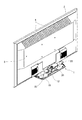
図1は、本発明の一実施形態のスタンドを設置した表示装置の斜視図である。本実施形態のスタンド1は1本脚構造であり、表示装置(例えば薄型のテレビ)2の中央(パネルセンタともいう)の下部に取り付けられている。なお、図1では表示装置2を左斜め後方から見ており、表示装置2の背面3には例えば放熱用の穴4が複数設けられている。
(Embodiment 1)
FIG. 1 is a perspective view of a display device provided with a stand according to an embodiment of the present invention. The
表示装置2は、スタンド1のスイベル機構によって水平方向に回動することにより、表示画面の向きを変更することができる。スタンド1の構成と動作を以下に詳細に説明する。
The
図2は、スタンドの分解斜視図である。スタンド1は、ベース部(スタンドベースともいう)10と、サポート部(スタンドサポートともいう)20とからなる。ベース部10やサポート部20は例えば樹脂製である。
ベース部10は、上記パネルセンタに相当する位置に回動支持部材11を有し、表示装置の正面側、つまり、回動支持部材11の前方は例えば開口されて枠状に形成され、回動支持部材11の後方は閉塞されて板状に形成されている。
FIG. 2 is an exploded perspective view of the stand. The
The
回動支持部材11は、例えば円筒状の金属製であり、例えばベース部10に対して回転できる。なお、図示の回動支持部材11は、ベース部10に対して直立して設けられているが、ベース部10に対して傾斜して設けられていてもよい。また、回動支持部材11は、表示装置を回動支持可能であれば、固定軸であってもよいし、回動軸を支持する部材であってもよい。
また、ベース部10は、回動支持部材11の後方に後述の固定ギア12を有している。固定ギア12は、例えば炭素鋼製であり、回動支持部材11に対向する面に歯形が形成されている。また、固定ギア12はベース部10に例えばネジで固定される。
The
In addition, the
サポート部20は、例えば細長い板状に形成され、回動支持部材11と一体的に回転できる。サポート部20には、例えば、回動支持部材11の回動中心に対してベース部10の奥行き方向(表示装置の前後方向)で見たやや前寄りに、図4に示すような支持台21が設置され、表示装置2を保持可能に構成されている。
また、サポート部20は駆動ユニット30を有している。詳しくは、駆動ユニット30は、支持台21の後方に配置されており、設置板22を介してサポート部20に例えばネジで固定されている。
The
In addition, the
このように、駆動ユニット30を、ベース部10ではなく、サポート部20に設けたため、ベース部10に対する意匠上の制約を少なくすることできる。また、駆動ユニット30を表示装置の背面側に設ければ、駆動ユニット30が表示装置の正面側からは見えにくくなることから、設計を含むデザイン性の高いスタンド付きの表示装置の提供に貢献する。
As described above, since the
図3(A)は駆動ユニットの斜視図、図3(B)は駆動ユニットの平面図である。また、図4は、スタンドの部分断面図である。
なお、図3(A)は駆動ユニットを表示装置の正面側から見た図であり、図3(B)では図示の下側が表示装置の正面側に相当する。この図3(B)では、駆動ユニットの内部構造を説明するために、後述のユニットカバー32を省略している。また、図4では、ベース部10の固定ギア12や駆動ユニット30を断面で示している。
3A is a perspective view of the drive unit, and FIG. 3B is a plan view of the drive unit. FIG. 4 is a partial cross-sectional view of the stand.
3A is a diagram of the drive unit as viewed from the front side of the display device. In FIG. 3B, the lower side of the drawing corresponds to the front side of the display device. In FIG. 3B, a
図3(A)に示すように、駆動ユニット30は、カップ状のユニットベース31を有し、後述の電動モータ33、歯車列や駆動軸39を収納し、板状のユニットカバー32で覆われている。なお、ユニットベース31やユニットカバー32は例えばアルミニウム製である。また、図示のユニットベース31は設置板22と一体形成されているが、別個に形成してもよい。
As shown in FIG. 3A, the
図3(B)に示すように、電動モータ33は、例えばアルミニウム製のモータホルダ33aを介してユニットベース31に例えばネジで固定されている。電動モータ33は、その回転量・回転方向・回転速度が制御可能な例えばACサーボモータなどであり、制御部(図示省略)からの駆動信号に基づいて、電動モータ33の回転軸に設置された例えば樹脂製のウオームギア34を正逆転可能である。
As shown in FIG. 3B, the
電動モータ33の近傍には、例えば炭素鋼製の第1ギア35が設けられている。第1ギア35は、ウオームギア34に噛み合う第1大径ギア35a、および、第1大径ギア35aの上側で一体形成された第1小径ギア35bで構成され、ユニットベース31やユニットカバー32に対して回転自在に支持される。
第1ギア35の近傍には、例えば炭素鋼製の第2ギア36が設けられている。第2ギア36は、第1小径ギア35bに噛み合う第2大径ギア36a、および、図4に示すような第2大径ギア36aの下側で一体形成された第2小径ギア36bで構成され、ユニットベース31などに対して回転自在に支持されている。
In the vicinity of the
In the vicinity of the
駆動軸39は、例えば炭素鋼で形成され、第2ギア36の近傍に設けられている。具体的には、駆動軸39は、図4に示すように、ユニットカバー32の上方に突出するとともに、ユニットベース31の下方にも突出しており、軸受40,41を介してユニットベース31などに対して回転自在に支持されている。
なお、軸受40は、ユニットカバー32に設置された例えばアルミニウム製の軸受ホルダ42で保持され、例えば炭素鋼製のカラー43で固定されている。また、軸受41は、ユニットベース31に設置されている。
The
The
また、駆動軸39には、例えば炭素鋼製の第3ギア37や同じく例えば炭素鋼製の可動ギア38が設けられており、第3ギア37や可動ギア38は、駆動軸39と一体的に回転できる。
第3ギア37は、ユニットベース31に収納され、図4で説明した第2小径ギア36bに噛み合っている。
The
The
一方、可動ギア38は、第3ギア37と同心で駆動軸39に設けられているが、駆動軸39の下端に設けられており、ユニットベース31の下方、つまり、駆動ユニット30の外部で、ベース部10の固定ギア12に噛み合っている。
そして、図4に示すように、可動ギア38は、回動支持部材11と固定ギア12との間に配置されている。
On the other hand, the
As shown in FIG. 4, the
このように、可動ギア38を回動支持部材11と固定ギア12との間に配置すれば、固定ギアを回動支持部材と可動ギアとの間に配置した場合に比べて、ベース部10の奥行きに要するスペースを小さくすることができる。
また、可動ギア38は、その下端側が、図4に示すような駆動軸39の回転軸線を通る断面で見て円弧状(面取り部R1ともいう)に形成されている。
As described above, when the
Further, the lower end side of the
上記のように、例えば、支持台21を回動支持部材11の回動中心よりも前寄りに配置したため、表示装置は前方へ傾きやすくなる。しかし、可動ギア38の下端側を円弧状に形成すれば、表示装置の前方への傾斜とともに、駆動軸39の上端も前方へ傾斜しても、可動ギア38と固定ギア12との滑らかな噛合を維持できるので、スイベル機能の信頼性を高めることができる。
As described above, for example, since the
図5は、スタンドの動作を説明するための図である。なお、図5では、ベース部10の固定ギア12と駆動ユニット30の可動ギア38との関係を説明するために、表示装置などを省略している。
例えば図5(A)に示すように、可動ギア38は固定ギア12のほぼ中央に位置しており、表示装置の表示画面は真正面を向く。
FIG. 5 is a diagram for explaining the operation of the stand. In FIG. 5, a display device and the like are omitted in order to explain the relationship between the fixed
For example, as shown in FIG. 5 (A), the
そして、図3(B)で説明した電動モータ33の駆動に伴って第1ギア35、第2ギア36、第3ギア37の順に回転し、駆動軸39が平面視で例えば反時計回りに回転すると、図5(B)に示すように、可動ギア38は固定ギア12の歯形の形成範囲で回動し、サポート部20の一端(図5(B)で見たサポート部20の右端)が前方に向けて移動するので、表示画面の向きが左向きに変更される。
Then, the
このように電動スイベル機能が実現されると、例えばIoT(Internet of Things)などの普及により、表示装置の表示画面を遠隔操作で回動させることも可能になる。 When the electric swivel function is realized as described above, for example, with the spread of IoT (Internet of Things), the display screen of the display device can be rotated remotely.
(実施形態2)
図6は、スタンドの他の実施形態を説明する図である。この図6でも、図4と同様に、ベース部10の固定ギア12と駆動ユニット30を断面で示している。
この実施形態2でも上記実施形態1と同様に、ベース部10が、回動支持部材11の後方に固定ギア12を有しているが、実施形態2で説明する固定ギア12は、図6に示すように、回動支持部材11と駆動ユニット30の可動ギア38との間に配置されている。
(Embodiment 2)
FIG. 6 is a diagram for explaining another embodiment of the stand. Also in FIG. 6, the fixed
In the second embodiment, as in the first embodiment, the
このように、固定ギア12を回動支持部材11と可動ギア38との間に配置すれば、可動ギアを回動支持部材と固定ギアとの間に配置した場合に比べて、ベース部10の奥行きで見て表示装置の背面から駆動ユニットまでの距離が長くなるので、表示装置の安定性が向上する。
この場合、可動ギア38は、その上端側が、図6に示すような駆動軸39の回転軸線を通る断面で見て円弧状(面取り部R2ともいう)に形成されている。
As described above, if the fixed
In this case, the upper end side of the
この結果、表示装置が前方へ傾きやすくなったとしても、可動ギア38の上端側を円弧状に形成すれば、可動ギア38と固定ギア12との滑らかな噛合を維持でき、スイベル機能の信頼性の高めることができる。
As a result, even if the display device easily tilts forward, if the upper end side of the
(実施形態3)
上記実施形態1では、可動ギア38の下端側を円弧状に形成し、上記実施形態2では、可動ギア38の上端側を円弧状に形成した例を挙げて説明したが、可動ギアは、その上端側および下端側の双方を側面視で円弧状に形成することも可能である。
(Embodiment 3)
In the first embodiment, the lower end side of the
(実施形態4)
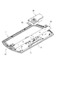
ところで、防塵構造のスタンドであってもよい。図7は、実施形態4におけるサポート部およびベース部の外観斜視図であり、図8は、サポート部およびベース部の分解斜視図である。また、図9は、第1スライドカバーおよび第2スライドカバーの外観斜視図であり、図10は、サポート部の背面図である。
(Embodiment 4)
By the way, a stand having a dustproof structure may be used. FIG. 7 is an external perspective view of a support portion and a base portion in
図7(A)はサポート部20やベース部10を左斜め後方から見ており、ベース部10は図8に示す可動ギア38、固定ギア12や位置検出板14を収納可能な防塵ボックス13を有し、防塵ボックス13は図2で説明した回動支持部材11の後方に配置される。図8に示すように、防塵ボックス13は、例えばカップ状で形成され、上方に可動ギア38や固定ギア12を受容する上方開口13cを有し、その周囲に側面13bが立設されている。側面13bの下端には、固定ギア12の脚部12aを挿通可能な下面13aが設けられている。
7A shows the
固定ギア12は脚部12aの上方に台状部12bを有し、台状部12bの側面には、可動ギア38に噛み合う歯形が形成されている。台状部12bの上面には位置検出板14が設置される。位置検出板14には、例えば中央位置、左15°の位置、右15°の位置に相当する位置に、白色や銀色のマークが設けられている。
The fixed
サポート部20の駆動ユニット30は、平板状のユニットベース31を有している。ユニットベース31は、図7(B)に示した下面47が回転支持部材11の上面に例えば直に連結されており、回転支持部材11と一体的に回転できる。一方、ユニットベース31の上面45には、図4で説明した支持台21を固定できる。
図7(A),(B)や図10に示すように、ユニットベース31には、上面45と下面47を貫通して設けられた曲線状のスライドカバー用の開口46が設けられ、図8や図9に示す第1スライドカバー60の上向き突起64、第2スライドカバー70の上向き突起74を例えば下方から受け入れ可能である。
The
As shown in FIGS. 7A and 7B and FIG. 10, the
図10に示すように、ユニットベース31は、スライドカバー用の開口46の後側に、矩形状のフォトセンサ用の開口47aを有している。この開口47aも上面45と下面47を貫通して形成されている。また、フォトセンサ用の開口47aの左右両側には、ハーフパンチ部48、49が設けられる。ハーフパンチ部48は、図10で見てフォトセンサ用の開口47aの右側に位置し、ユニットベース31の下面47から下方に向けて突出しており、第1スライドカバー60の開口63の端部に当接可能である。ハーフパンチ部49は、図10で見てフォトセンサ用の開口47aの左側に位置し、ユニットベース31の下面47から下方に向けて突出し、第2スライドカバー70の開口73の端部に当接可能である。
As shown in FIG. 10, the
図8に示すように、駆動軸39は電動モータ33に対して回転自在に支持されている。駆動軸39の下端には可動ギア38が設けられ、ユニットベース31の下方で固定ギア12に噛み合っている。電動モータ33は、略筒状のばねガイドリング50を用いてユニットベース31の上面45に固定される。
ばねガイドリング50は、内面で電動モータ33を案内し、外面で引張りばね55を案内する案内部53を有し、案内部53の中央には、駆動軸39を挿通させる中央孔(図示省略)が形成されている。案内部53の前側には、ユニットベース31の上面45に例えばネジで固定するための固定部52が設けられ、案内部53の後側には、プリント基板56を下方に押える押圧部54が設けられている。
As shown in FIG. 8, the
The
引張りばね55は、2分割された第1,2スライドカバー60,70の位置を戻すためのものであり、引張りばね55の一端は第1スライドカバー60の上向き突起64に、他端は第2スライドカバー70の上向き突起74にそれぞれ取り付けられる。
プリント基板56は、裏面の中央にフォトセンサ57を設置し、ばねガイドリング50の押圧部54に上方から押さえられて、ユニットベース31の上面45に固定される。
The
The printed
フォトセンサ57は下方に位置する位置検出板14に向けて光を照射でき、位置検出板14の白色や銀色の各マークで反射した光をフォトセンサ57で検出することにより、駆動ユニット30の回動位置を得ることができる。
第1スライドカバー60は平面視で左側に、第2スライドカバー70は平面視で右側にそれぞれ配置され、ユニットベース31の回動にそれぞれ連動可能である。
The
The
図9(A)に示すように、第1スライドカバー60は、図8で説明した防塵ボックス13の上方開口13cに覆い被さる水平面部61を有し、上向き突起64は水平面部61の上面から上方に向けて突出し、引張りばね55の端部を保持できる。上向き突起64の前側には、駆動軸39を受容するための駆動軸用の開口62が曲線状で設けられ、上向き突起64の後側には、フォトセンサ57を受容するためのフォトセンサ用の開口63が曲線状で設けられている。
As shown in FIG. 9A, the
第1スライドカバー60はユニットベース31の下方に配置され、上向き突起64を、ユニットベース31の下方からスライドカバー用の開口46に遊嵌させて、ユニットベース31の上方に突出させる。
また、図9(B)に示すように、第1スライドカバー60はL字状の下向き突片65を有している。下向き突片65は、水平面部61の前端から側端にかけて形成され、水平面部61から下方に突出しており、図7(B)に示したように、防塵ボックス13の側面13bに接触可能に形成されている。
The
As shown in FIG. 9B, the
第2スライドカバー70も、第1スライドカバー60と同様に、防塵ボックス13の上方開口13cに覆い被さる水平面部71を有する。上向き突起74は水平面部71の上面から上方に向けて突出している。上向き突起74の前側には、駆動軸39を通すための駆動軸用の開口72が曲線状で設けられ、上向き突起74の後側には、フォトセンサ57を受容するためのフォトセンサ用の開口73が曲線状で設けられている。第2スライドカバー70もユニットベース31の下方に配置され、上向き突起74はスライドカバー用の開口46に遊嵌する。
Similarly to the
また、図9(B)に示すように、第2スライドカバー70も、水平面部71の前端から側端にかけて形成されたL字状の下向き突片75を有し、防塵ボックス13の側面13bに接触可能である。
Further, as shown in FIG. 9B, the
図11は、スタンドの動作を説明するための図である。なお、図11では、ユニットベース31と第1,2スライドカバー60,70との関係を説明するために、表示装置や防塵ボックス13、引張りばね55などを省略している。
可動ギア38が固定ギア12のほぼ中央に位置し、表示装置の表示画面が真正面を向いていた状態において、電動モータ33の駆動に伴って駆動軸39が平面視で例えば時計回りに回転し始めると、ユニットベース31の一端(図11(A)で見たユニットベース31の左端)が前方に向けて移動(回動)を開始する。
FIG. 11 is a diagram for explaining the operation of the stand. In FIG. 11, in order to explain the relationship between the
In a state where the
ユニットベース31の一端が回動を開始した後、図11(B)に示すように、ユニットベース31のハーフパンチ部48が第1スライドカバー60のフォトセンサ用の開口63の端部に接触すると、第1スライドカバー60の下向き突片65と防塵ボックス13の側面13bとの接触が解かれる。そして、第1スライドカバー60は、引張りばね55の付勢力に抗して、防塵ボックス13の上方開口13cを覆いつつ、ユニットベース31と共に回動を開始する。
After one end of the
一方、第1スライドカバー60がユニットベース31の回動に連動して防塵ボックス13の上方開口13cを覆う際に、第2スライドカバー70の下向き突片75と防塵ボックス13の側面13bとの接触は解かれないため、図11(B)に示すように第1スライドカバー60がユニットベース31と共に回動しても、第2スライドカバー70は、回動せずに、防塵ボックス13の上方開口13cを覆い続ける。
そして、駆動軸39が平面視で例えば時計回りに回転すると、図11(A)に示すように、ユニットベース31の左端が回動するので、表示画面の向きが左向きに変更される。
On the other hand, when the
Then, when the
その後、フォトセンサ57の検出結果に基づき、駆動軸39が平面視で例えば反時計回りに回転した場合、ユニットベース31の一端(図11(A)で見たユニットベース31の右端)が前方に向けて移動(回動)を開始する。
ユニットベース31の一端が回動を開始した後、ハーフパンチ部48とフォトセンサ用の開口63の端部との接触が解かれると、第1スライドカバー60は、引張りばね55の付勢力によって、防塵ボックス13の上方開口13cを覆いつつ、下向き突片65が防塵ボックス13の側面13bに接触するまで、第2スライドカバー70に向けて移動する。
Thereafter, based on the detection result of the
After the one end of the
これに対して図示は省略するが、可動ギア38が固定ギア12のほぼ中央に位置し、表示装置の表示画面が真正面を向いていた状態において、電動モータ33の駆動に伴って駆動軸39が平面視で例えば反時計回りに回転し始めると、ユニットベース31の一端(図11(A)で見たユニットベース31の右端)が前方に向けて移動(回動)を開始する。
ユニットベース31の一端が回動を開始した後、ユニットベース31のハーフパンチ部49が第2スライドカバー70のフォトセンサ用の開口73の端部に接触すると、第2スライドカバー70の下向き突片75と防塵ボックス13の側面13bとの接触が解かれる。そして、第2スライドカバー70は、引張りばね55の付勢力に抗して、防塵ボックス13の上方開口13cを覆いつつ、ユニットベース31と共に回動を開始する。
On the other hand, although illustration is omitted, in the state where the
After one end of the
一方、第2スライドカバー70がユニットベース31の回動に連動して防塵ボックス13の上方開口13cを覆う際に、第1スライドカバー60の下向き突片65と防塵ボックス13の側面13bとの接触は解かれないため、第2スライドカバー70がユニットベース31と共に回動しても、第1スライドカバー60は、回動せずに、防塵ボックス13の上方開口13cを覆い続ける。
そして、駆動軸39が平面視で例えば反時計回りに回転すると、ユニットベース31の右端が回動するので、表示画面の向きが右向きに変更される。
On the other hand, when the
When the
その後、フォトセンサ57の検出結果に基づき、駆動軸39が平面視で例えば時計回りに回転した場合、ユニットベース31の一端(図11(A)で見たユニットベース31の左端)が前方に向けて移動(回動)を開始する。
ユニットベース31の一端が回動を開始した後、ハーフパンチ部49とフォトセンサ用の開口73の端部との接触が解かれると、第2スライドカバー70は、引張りばね55の付勢力によって、防塵ボックス13の上方開口13cを覆いつつ、下向き突片75が防塵ボックス13の側面13bに接触するまで、第1スライドカバー60に向けて移動する。
Thereafter, based on the detection result of the
After the one end of the
このように、ユニットベース31には、防塵ボックス13の上方開口13cを覆う第1,2スライドカバー60,70が設置されているので、防塵ボックス13内への塵埃の侵入を防止することができる。
また、図11に示した動作で説明すれば、ユニットベース31の回動に遅れて連動する第1スライドカバー60と、ユニットベース31の回動に連動しない第2スライドカバー70とに分割されていることから、第1,2スライドカバー60,70を一体形成した場合に比べてユニットベース31の幅(左右方向の長さ)を短くすることができ、駆動ユニット30の小型化を達成することができる。
As described above, the
11, the operation is divided into a
1…スタンド、2…表示装置、3…背面、4…穴、10…ベース部、11…回動支持部材、12…固定ギア、12a…脚部、12b…台状部、13…防塵ボックス、13a…下面、13b…側面、13c…上方開口、14…位置検出板、20…サポート部、21…支持台、22…設置板、30…駆動ユニット、31…ユニットベース、32…ユニットカバー、33…電動モータ、33a…モータホルダ、34…ウオームギア、35…第1ギア、35a…第1大径ギア、35b…第1小径ギア、36…第2ギア、36a…第2大径ギア、36b…第2小径ギア、37…第3ギア、38…可動ギア、39…駆動軸、40,41…軸受、42…軸受ホルダ、43…カラー、45…上面、46…スライドカバー用の開口、47…下面、47a…フォトセンサ用の開口、48,49…ハーフパンチ部、50…ばねガイドリング、52…固定部、53…案内部、54…押圧部、55…引張りばね、56…プリント基板、57…フォトセンサ、60…第1スライドカバー、61,71…水平面部、62,72…駆動軸用の開口、63,73…フォトセンサ用の開口、64,74…上向き突起、65,75…下向き突片、70…第2スライドカバー。
DESCRIPTION OF
上記課題を解決するために、本発明の第1の技術手段は、表示装置を保持するために用いられるスタンドであって、該スタンドは、ベース部と、該ベース部に対して回動するとともに、前記表示装置を保持するサポート部とを備え、該サポート部が、前記表示装置の表示画面を回動させるための駆動ユニットを有し、該駆動ユニットが、前記表示装置の表示画面の背面側に設けられ、駆動軸と、該駆動軸とともに回動する可動ギアを有し、前記ベース部が、前記表示装置を回動支持する回動支持部材と、前記可動ギアに噛合する固定ギアとを有し、前記可動ギアが前記回動支持部材と前記固定ギアとの間に配置され、前記可動ギアは、前記駆動ユニットから下方に延びた前記駆動軸の下端に設けられ、該可動ギアの少なくとも下端側が、前記駆動軸の回転軸線を通る断面で見て円弧状に形成されていることを特徴としたものである。 In order to solve the above problems, a first technical means of the present invention is a stand used for holding a display device, and the stand rotates with respect to the base portion and the base portion. A support unit for holding the display device, and the support unit has a drive unit for rotating the display screen of the display device, and the drive unit is on the back side of the display screen of the display device. A drive shaft, a movable gear that rotates with the drive shaft, and a rotation support member that supports the display device to rotate, and a fixed gear that meshes with the movable gear. The movable gear is disposed between the rotation support member and the fixed gear, and the movable gear is provided at a lower end of the drive shaft extending downward from the drive unit, and at least of the movable gear The lower end side is It is obtained by said that viewed in cross-section through the shaft axis of rotation are formed in an arc shape.
第2の技術手段は、表示装置を保持するために用いられるスタンドであって、該スタンドは、ベース部と、該ベース部に対して回動するとともに、前記表示装置を保持するサポート部とを備え、該サポート部が、前記表示装置の表示画面を回動させるための駆動ユニットを有し、該駆動ユニットが、前記表示装置の表示画面の背面側に設けられ、駆動軸と、該駆動軸とともに回動する可動ギアを有し、前記ベース部が、前記表示装置を回動支持する回動支持部材と、前記可動ギアに噛合する固定ギアとを有し、前記固定ギアが前記回動支持部材と前記可動ギアとの間に配置され、前記可動ギアは、前記駆動ユニットから下方に延びた前記駆動軸の下端に設けられ、該可動ギアの少なくとも上端側が、前記駆動軸の回転軸線を通る断面で見て円弧状に形成されていることを特徴としたものである。 The second technical means is a stand used for holding the display device, and the stand includes a base portion and a support portion that rotates with respect to the base portion and holds the display device. The support unit has a drive unit for rotating the display screen of the display device, and the drive unit is provided on the back side of the display screen of the display device. And the base portion includes a rotation support member that rotatably supports the display device, and a fixed gear that meshes with the movable gear, and the fixed gear supports the rotation. The movable gear is disposed between a member and the movable gear, and the movable gear is provided at a lower end of the drive shaft extending downward from the drive unit, and at least an upper end side of the movable gear passes through a rotation axis of the drive shaft. Circle seen in cross section It is obtained by said formed in Jo.
第3の技術手段は、表示装置を保持するために用いられるスタンドであって、該スタンドは、ベース部と、該ベース部に対して回動するとともに、前記表示装置を保持するサポート部とを備え、該サポート部が、前記表示装置の表示画面を回動させるための駆動ユニットを有し、該駆動ユニットが、前記表示装置の表示画面の背面側に設けられ、駆動軸と、該駆動軸とともに回動する可動ギアと、前記駆動軸を配置させ、前記表示装置の表示画面を回動させるために回動可能に構成されたユニットベースとを有し、前記ベース部が、前記可動ギアに噛合する固定ギアと、前記可動ギアおよび前記固定ギアを収容する防塵ボックスとを有しており、前記ユニットベースの回動にそれぞれ連動可能な2つのスライドカバーをさらに有し、一方の前記スライドカバーが前記ユニットベースの回動に連動して前記防塵ボックスを覆う際に、他方の前記スライドカバーは、前記ユニットベースの回動に連動せずに、前記防塵ボックスを覆うことを特徴としたものである。 A third technical means is a stand used for holding the display device, and the stand includes a base portion and a support portion that rotates with respect to the base portion and holds the display device. with, the support unit has a drive unit for rotating the display screen of the display device, the drive unit is provided on the back side of the display screen of the display device, and shaft drive, the drive A movable gear that rotates together with the shaft; and a unit base that is arranged to rotate the display screen of the display device by disposing the drive shaft, and the base portion includes the movable gear. A fixed gear that meshes with the movable base, and a dust-proof box that houses the movable gear and the fixed gear, and further includes two slide covers that can be interlocked with the rotation of the unit base. When the slide cover covers the dustproof box in conjunction with the rotation of the unit base, the other slide cover covers the dustproof box without being interlocked with the rotation of the unit base. Is.
第4の技術手段は、第1から第3のいずれか1の技術手段において、前記駆動ユニットが電動モータを有し、該電動モータの駆動によって前記表示装置の表示画面を回動させることを特徴としたものである。
第5の技術手段は、第1から第4のいずれか1の技術手段を備えたテレビジョン装置であることを特徴としたものである。
According to a fourth technical means, in any one of the first to third technical means, the drive unit includes an electric motor, and the display screen of the display device is rotated by driving the electric motor. It is what.
The fifth technical means is a television apparatus including any one of the first to fourth technical means.
Claims (8)
該スタンドは、ベース部と、該ベース部に対して回動するとともに、前記表示装置を保持するサポート部とを備え、
該サポート部が、前記表示装置の表示画面を回動させるための駆動ユニットを有し、
該駆動ユニットが、前記表示装置の表示画面の背面側に設けられていることを特徴とするスタンド。 A stand used to hold a display device,
The stand includes a base portion and a support portion that rotates relative to the base portion and holds the display device.
The support unit has a drive unit for rotating the display screen of the display device,
A stand characterized in that the drive unit is provided on the back side of the display screen of the display device.
前記ベース部が、前記表示装置を回動支持する回動支持部材と、前記可動ギアに噛合する固定ギアとを有し、
前記可動ギアが前記回動支持部材と前記固定ギアとの間に配置されることを特徴とする請求項1または2に記載のスタンド。 The drive unit has a drive shaft and a movable gear that rotates with the drive shaft;
The base portion includes a rotation support member that rotatably supports the display device, and a fixed gear that meshes with the movable gear,
The stand according to claim 1 or 2, wherein the movable gear is disposed between the rotation support member and the fixed gear.
前記ベース部が、前記表示装置を回動支持する回動支持部材と、前記可動ギアに噛合する固定ギアとを有し、
前記固定ギアが前記回動支持部材と前記可動ギアとの間に配置されることを特徴とする請求項1または2に記載のスタンド。 The drive unit has a drive shaft and a movable gear that rotates with the drive shaft;
The base portion includes a rotation support member that rotatably supports the display device, and a fixed gear that meshes with the movable gear,
The stand according to claim 1 or 2, wherein the fixed gear is disposed between the rotation support member and the movable gear.
前記ベース部が、前記可動ギアに噛合する固定ギアと、前記可動ギアおよび前記固定ギアを収容する防塵ボックスとを有しており、
前記ユニットベースの回動にそれぞれ連動可能な2つのスライドカバーをさらに有し、
一方の前記スライドカバーが前記ユニットベースの回動に連動して前記防塵ボックスを覆う際に、他方の前記スライドカバーは、前記ユニットベースの回動に連動せずに、前記防塵ボックスを覆うことを特徴とする請求項1から6のいずれか一項に記載のスタンド。 The drive unit includes a drive shaft, a movable gear that rotates together with the drive shaft, and a unit base that is configured to rotate to dispose the drive shaft and rotate the display screen of the display device. Have
The base portion includes a fixed gear that meshes with the movable gear, and a dustproof box that houses the movable gear and the fixed gear,
And further comprising two slide covers that can be linked to the rotation of the unit base,
When one of the slide covers covers the dustproof box in conjunction with the rotation of the unit base, the other slide cover covers the dustproof box without being interlocked with the rotation of the unit base. The stand according to any one of claims 1 to 6, characterized in that:
A television apparatus comprising the stand according to any one of claims 1 to 7.
Priority Applications (3)
| Application Number | Priority Date | Filing Date | Title |
|---|---|---|---|
| CN201780010455.3A CN109076184A (en) | 2016-04-15 | 2017-02-07 | Stands and TV installations |
| US16/079,062 US10634277B2 (en) | 2016-04-15 | 2017-02-07 | Stand and television apparatus |
| PCT/JP2017/004438 WO2017179275A1 (en) | 2016-04-15 | 2017-02-07 | Stand and television apparatus |
Applications Claiming Priority (2)
| Application Number | Priority Date | Filing Date | Title |
|---|---|---|---|
| JP2016082024 | 2016-04-15 | ||
| JP2016082024 | 2016-04-15 |
Publications (2)
| Publication Number | Publication Date |
|---|---|
| JP6178935B1 JP6178935B1 (en) | 2017-08-09 |
| JP2017194664A true JP2017194664A (en) | 2017-10-26 |
Family
ID=59559177
Family Applications (1)
| Application Number | Title | Priority Date | Filing Date |
|---|---|---|---|
| JP2017009451A Expired - Fee Related JP6178935B1 (en) | 2016-04-15 | 2017-01-23 | Stand and television apparatus |
Country Status (4)
| Country | Link |
|---|---|
| US (1) | US10634277B2 (en) |
| JP (1) | JP6178935B1 (en) |
| CN (1) | CN109076184A (en) |
| WO (1) | WO2017179275A1 (en) |
Families Citing this family (1)
| Publication number | Priority date | Publication date | Assignee | Title |
|---|---|---|---|---|
| KR102373510B1 (en) * | 2017-08-11 | 2022-03-11 | 삼성전자주식회사 | Display device for visualizing contents as the display is rotated and control method thereof |
Citations (4)
| Publication number | Priority date | Publication date | Assignee | Title |
|---|---|---|---|---|
| JPH06341395A (en) * | 1993-06-02 | 1994-12-13 | I Towanii:Kk | Neck oscillating structure of electric fan |
| JP2007171355A (en) * | 2005-12-20 | 2007-07-05 | Sanyo Electric Co Ltd | Display device |
| JP2008109407A (en) * | 2006-10-25 | 2008-05-08 | Toyo Vending Kk | Television set with remote control for headboard |
| JP2010243871A (en) * | 2009-04-08 | 2010-10-28 | Mitsubishi Electric Corp | Turntable for display device |
Family Cites Families (8)
| Publication number | Priority date | Publication date | Assignee | Title |
|---|---|---|---|---|
| WO2004028151A1 (en) * | 2002-09-17 | 2004-04-01 | Sharp Kabushiki Kaisha | Thin display device |
| JP4873228B2 (en) * | 2006-03-31 | 2012-02-08 | 下西技研工業株式会社 | Rotating device for flat display |
| JP2007295379A (en) * | 2006-04-26 | 2007-11-08 | Funai Electric Co Ltd | Thin-screen television receiver |
| CN2924962Y (en) * | 2006-07-05 | 2007-07-18 | 四川长虹电器股份有限公司 | Flat panel television receiver body rotation driving device |
| US7854415B2 (en) * | 2006-12-04 | 2010-12-21 | Peerless Industries, Inc. | Motorized support for a television or other electronic display |
| JP5128994B2 (en) | 2008-03-31 | 2013-01-23 | 株式会社村上開明堂 | Rotating stand |
| JP5241308B2 (en) * | 2008-05-02 | 2013-07-17 | 三菱電機株式会社 | Turntable for display device |
| CN101446378A (en) * | 2008-11-21 | 2009-06-03 | 宁波丽晶时代电子线缆有限公司 | LCD television hanging frame with adjustable motor angle |
-
2017
- 2017-01-23 JP JP2017009451A patent/JP6178935B1/en not_active Expired - Fee Related
- 2017-02-07 CN CN201780010455.3A patent/CN109076184A/en active Pending
- 2017-02-07 US US16/079,062 patent/US10634277B2/en active Active
- 2017-02-07 WO PCT/JP2017/004438 patent/WO2017179275A1/en not_active Ceased
Patent Citations (4)
| Publication number | Priority date | Publication date | Assignee | Title |
|---|---|---|---|---|
| JPH06341395A (en) * | 1993-06-02 | 1994-12-13 | I Towanii:Kk | Neck oscillating structure of electric fan |
| JP2007171355A (en) * | 2005-12-20 | 2007-07-05 | Sanyo Electric Co Ltd | Display device |
| JP2008109407A (en) * | 2006-10-25 | 2008-05-08 | Toyo Vending Kk | Television set with remote control for headboard |
| JP2010243871A (en) * | 2009-04-08 | 2010-10-28 | Mitsubishi Electric Corp | Turntable for display device |
Also Published As
| Publication number | Publication date |
|---|---|
| US10634277B2 (en) | 2020-04-28 |
| US20190040992A1 (en) | 2019-02-07 |
| CN109076184A (en) | 2018-12-21 |
| JP6178935B1 (en) | 2017-08-09 |
| WO2017179275A1 (en) | 2017-10-19 |
Similar Documents
| Publication | Publication Date | Title |
|---|---|---|
| US10492607B2 (en) | Image sound device having display portion that can appear/disappear | |
| JP5106672B1 (en) | Electronics | |
| JP6178935B1 (en) | Stand and television apparatus | |
| JP5700198B2 (en) | Rotating display device | |
| JP5669653B2 (en) | Document imaging device | |
| US20160058190A1 (en) | Video display unit and mounting unit | |
| JP2007295379A (en) | Thin-screen television receiver | |
| JP2014191089A (en) | Display device | |
| JP5988605B2 (en) | Video projection device | |
| JP5377700B2 (en) | Rotation mechanism of automatic induction laser irradiator | |
| JP6167828B2 (en) | Image reading device | |
| JP2019028103A (en) | Stand and television device | |
| JP2019028104A (en) | Stand and television apparatus | |
| JP2004212465A (en) | Camera for remote control | |
| JP4555245B2 (en) | Lens shift mechanism and projection display device | |
| JP2014115459A (en) | Rotation mechanism for display device | |
| JP5803230B2 (en) | Operating device | |
| JP5930936B2 (en) | Automotive electronics | |
| JP2008219539A (en) | Display device turntable and display device provided with it | |
| CN102590980A (en) | Lens focusing device | |
| JP6715664B2 (en) | Rotation mechanism and display device | |
| KR20140126036A (en) | Display apparatus | |
| JP6273775B2 (en) | Light emitting device and image display system | |
| JP2014096713A (en) | Image reading apparatus, and method of manufacturing the same | |
| JP2005302569A (en) | Input device |
Legal Events
| Date | Code | Title | Description |
|---|---|---|---|
| A131 | Notification of reasons for refusal |
Free format text: JAPANESE INTERMEDIATE CODE: A131 Effective date: 20170502 |
|
| A521 | Written amendment |
Free format text: JAPANESE INTERMEDIATE CODE: A523 Effective date: 20170623 |
|
| TRDD | Decision of grant or rejection written | ||
| A01 | Written decision to grant a patent or to grant a registration (utility model) |
Free format text: JAPANESE INTERMEDIATE CODE: A01 Effective date: 20170711 |
|
| A61 | First payment of annual fees (during grant procedure) |
Free format text: JAPANESE INTERMEDIATE CODE: A61 Effective date: 20170714 |
|
| R150 | Certificate of patent or registration of utility model |
Ref document number: 6178935 Country of ref document: JP Free format text: JAPANESE INTERMEDIATE CODE: R150 |
|
| LAPS | Cancellation because of no payment of annual fees |