JP2017193855A - Partition unit - Google Patents
Partition unit Download PDFInfo
- Publication number
- JP2017193855A JP2017193855A JP2016084078A JP2016084078A JP2017193855A JP 2017193855 A JP2017193855 A JP 2017193855A JP 2016084078 A JP2016084078 A JP 2016084078A JP 2016084078 A JP2016084078 A JP 2016084078A JP 2017193855 A JP2017193855 A JP 2017193855A
- Authority
- JP
- Japan
- Prior art keywords
- partition
- vertical
- partition unit
- partition wall
- door
- Prior art date
- Legal status (The legal status is an assumption and is not a legal conclusion. Google has not performed a legal analysis and makes no representation as to the accuracy of the status listed.)
- Granted
Links
- 238000005192 partition Methods 0.000 title claims abstract description 59
- 239000000463 material Substances 0.000 claims abstract description 7
- 239000011521 glass Substances 0.000 claims description 10
- 239000002184 metal Substances 0.000 abstract description 2
- 238000010586 diagram Methods 0.000 description 2
- 238000000034 method Methods 0.000 description 2
- 238000004378 air conditioning Methods 0.000 description 1
- 238000010276 construction Methods 0.000 description 1
- 238000009434 installation Methods 0.000 description 1
- 238000012856 packing Methods 0.000 description 1
- 239000007787 solid Substances 0.000 description 1
- 239000002023 wood Substances 0.000 description 1
Images


Landscapes
- Wing Frames And Configurations (AREA)
- Assembled Shelves (AREA)
Abstract
Description
本発明は、ドア部分の縦枠が容易に交換できる間仕切ユニットに関するものである。 The present invention relates to a partition unit in which a vertical frame of a door portion can be easily replaced.
従来、学校等の建物内において、廊下と教室を間仕切る間仕切壁は、出入り口、窓部、壁面、収納棚を一体化したユニットが用いられている。
Conventionally, in a building such as a school, a unit that integrates an entrance / exit, a window, a wall, and a storage shelf is used as a partition wall that partitions a hallway and a classroom.
しかし、これらのユニットは、金属製建具を主体とするものであって、機能性だけの殺風景なものであったが、近年、ぬくもりを感じる木質材料を用いた間仕切ユニットが用いられるようになった。 However, these units are mainly made of metal fittings and have only been killed by functionality. In recent years, partition units using wood materials that feel warmth have come to be used. .
例えば、特許文献1には、天井面と床面に木治具レールを敷設し、サッシュ窓や木製パネルを嵌込んだ門型の木製間仕切壁を木治具レール間に嵌込み、あるいは、床面の木治具レールを敷居レールとして引戸を嵌め込んだ門型の木製間仕切壁によって、迅速かつ容易に木製の間仕切ユニットを形成することができる。
For example, in
しかし、多くの子供が走り回る学校施設では、教室や廊下の壁や戸が破損する場合も多く、特に出入り口の引戸は頻繁かつ乱暴に開け閉めされたり、物をぶつけたりすることで、木製の縦枠が傷付き、著しくはひびが入ったり割れたりする場合もある。 However, in school facilities where many children run around, the walls and doors of classrooms and corridors are often damaged.In particular, the sliding doors at the entrance and exit are frequently opened and closed wildly, and the wooden vertical The frame may be scratched and cracked or cracked.
このような場合、特許文献1の各図面を見ればわかるように、木製間仕切壁は、枠が縦勝ち(縦枠で横枠を挟み込む)に形成されており、衝突し易く破損の可能性が極めて高い縦枠を交換するには、木製間仕切壁(引戸の枠部分)全体を取り外し分解して交換するため、手間と費用が極めてかかる。
In such a case, as can be seen from the drawings of
本発明は、特に学校施設のように破損の可能性の高いドア部分の縦枠を容易に補修交換できないという問題点に鑑みてなされた発明であり、その目的は、ドア部分の縦枠を容易に交換することができ、付随的には施工性を高めることができる間仕切ユニットに関するものである。 The present invention has been made in view of the problem that the vertical frame of a door part, which is highly likely to be damaged, such as a school facility, cannot be easily repaired and replaced. The purpose of the present invention is to facilitate the vertical frame of a door part. It is related with the partition unit which can be replaced | exchanged and can improve workability incidentally.
第1の発明は、天井躯体に固定した天井固定桟と壁躯体に固定した縦柱固定桟からなる下地材に、両端の縦柱とそれをつなぐ複数本の横柱からなる枠組の柱間に内装設備を設けた間仕切壁を複数横方向に並設し固定して得られる間仕切ユニットに関するもので、間仕切ユニットを構成する一部の間仕切壁の内装設備は縦柱と横柱と床面で形成される開口部にドアが設けられたドア設備であって、当該間仕切壁の縦柱の表面を被覆するように縦枠が固定されていることを特徴とする。 In the first invention, a base material composed of a ceiling fixing bar fixed to a ceiling frame and a vertical column fixing bar fixed to a wall frame, between vertical columns at both ends and a plurality of horizontal columns connecting the column columns. This is related to a partition unit obtained by arranging and fixing a plurality of partition walls provided with interior equipment in the horizontal direction. The interior equipment of some partition walls constituting the partition unit is formed by vertical columns, horizontal columns, and the floor surface. The door is provided with a door in the opening, and the vertical frame is fixed so as to cover the surface of the vertical column of the partition wall.
第1の発明では、間仕切ユニットの一部に設けられたドア設備の開口部の縦柱にその表面を被覆するように縦枠が固定されているので、縦枠の交換が容易に行える。 In the first invention, since the vertical frame is fixed so as to cover the surface of the vertical column of the opening of the door facility provided in a part of the partition unit, the vertical frame can be easily replaced.
第2の発明は、請求項1に記載の間仕切ユニットの一部の内装設備が収納棚であることを特徴とする。
The second invention is characterized in that a part of the interior equipment of the partition unit according to
第2の発明では、間仕切ユニットに最初から収納棚が組み込まれるので、後から収納工事を行う必要がない。 In the second invention, since the storage shelf is built into the partition unit from the beginning, it is not necessary to perform the storage work later.
第3の発明は、請求項2に記載の収納棚の背面側にガラスが嵌め込まれたことを特徴とする。 The third invention is characterized in that glass is fitted on the back side of the storage shelf according to claim 2.
第3の発明では、収納棚を設けても採光を得ることができ、通路側に向けて陳列棚にもなる。 In the third aspect of the invention, lighting can be obtained even if a storage shelf is provided, and the display shelf also becomes a display shelf toward the passage side.
本発明によると、縦柱の表面を被覆するように縦枠を固定することで、表面に出ている縦枠が傷付き、ひびが入ったり割れたりした際に縦枠の交換が容易に行える。また、縦枠は目に見える表面部分だけなので、交換のコストも安くなる。さらに、間仕切壁を立てた後に縦枠を現場の寸法に合わせて調整できるので縦柱を床面まで正確にカバーできるので、意匠性が良くなる。 According to the present invention, by fixing the vertical frame so as to cover the surface of the vertical column, the vertical frame can be easily replaced when the vertical frame on the surface is damaged, cracked or cracked. . Moreover, since the vertical frame is only a visible surface portion, the replacement cost is also reduced. Furthermore, since the vertical frame can be adjusted according to the field size after the partition wall is erected, the vertical column can be accurately covered to the floor surface, so that the design is improved.
また、従来は窓のあった部分の有効活用として、収納棚を設けることで、収納スペースを増やすことができ、間仕切ユニットに最初から収納棚が組み込まれるので、後から別に収納工事を行う必要がない。 In addition, the storage space can be increased by providing a storage shelf as an effective use of the part where there was a window in the past, and since the storage shelf is built into the partition unit from the beginning, it is necessary to perform separate storage work later. Absent.
さらに、収納棚の背面にガラスを設け嵌め込めば、室内の空調を快適に調整でき、廊下側からの採光を得ることができ、通路側に向けて生徒の作品等の陳列棚にもなる。また、通路側からいたずらされたり盗られたりすることを防止できる。 Furthermore, if glass is provided and fitted on the back of the storage shelf, the air conditioning in the room can be adjusted comfortably, the lighting from the corridor side can be obtained, and it becomes a display shelf for student's work and the like toward the passage side. Moreover, it can prevent being tampered with or stolen from the passage side.
以下、本発明の実施形態を図面に基づいて詳細に説明する。なお、以下の実施形態は、本質的に好ましい例示であって、本発明、その適用物、あるいはその用途の範囲を制限することを意図するものではない。 Hereinafter, embodiments of the present invention will be described in detail with reference to the drawings. The following embodiments are essentially preferable examples, and are not intended to limit the scope of the present invention, its application, or its use.
図1は、本発明の間仕切壁Wを複数横方向に並設し躯体に固定して得られる間仕切ユニットUの正面図である。図1では、間仕切ユニットUの骨組み(縦柱、横柱)が明確にわかるように、枠組の柱間に設ける内装設備を省略した。両端の縦柱1を横柱(上枠2、中鴨居3、3‘)でビス等を用いて接合した間仕切壁Wの柱間の空間に後述する内装設備を設けた後立設させ、上枠2を天井躯体に固定した天井固定桟4に天井固定金具21で固定すると共に、床面の不陸を縦柱1の下端に設けたアジャスター13で高さ調整のうえ、床固定金具12で床面に固定する。
FIG. 1 is a front view of a partition unit U obtained by arranging a plurality of partition walls W in the horizontal direction and fixing the partition walls W to a housing. In FIG. 1, the interior equipment provided between the columns of the frame is omitted so that the framework (vertical columns, horizontal columns) of the partition unit U can be clearly seen. The
間仕切壁Wは、複数(図1、2では4台)立設するが、端部にもうける間仕切壁Wの端部側の縦枠1を壁躯体に固定した縦柱固定桟5に壁固定金具11で固定すると共に、他方側の縦枠1を隣接する間仕切壁Wの縦枠1とをやとい実等で接合し、同様の作業を残り2台の間仕切壁Wに施すことで、図1に記載の間仕切ユニットUにより部屋と廊下を仕切ることができる。
A plurality of partition walls W (four in FIGS. 1 and 2) are erected, but wall fixing brackets are attached to the vertical column fixing bar 5 in which the
図2は、間仕切壁Wにおいて、間仕切壁Wを構成する両端の縦柱1とそれをつなぐ上枠2と中鴨居3、3‘からなる枠組の柱間に内装設備を設けた状態の図であり、最終完成した間仕切ユニットUの正面図である。ここで内装設備とは、ドア設備D、収納棚S、上窓Mが示されるが、その他普通の壁部分や腰壁と窓部分等、種々の設備が考えられる。
FIG. 2 is a diagram of the partition wall W in which interior equipment is provided between the columns of the frame made up of the
図3は、間仕切壁Wでドア設備Dを形成する場合を示すが、図面を見易くするため。内装設備(引戸)を省略して縦柱と横柱だけを示し、長尺部分を省略して一つの図面に収まるようにして間仕切壁Wの正面図を表した。以後、図6までは同様の方法で記載しており、その部分については説明を省略する。 Although FIG. 3 shows the case where the door installation D is formed with the partition wall W, in order to make drawing easy to see. The front view of the partition wall W was represented by omitting the interior equipment (sliding doors) and showing only the vertical and horizontal pillars, omitting the long portion, and fitting into one drawing. Hereinafter, the description up to FIG. 6 is performed in the same manner, and the description thereof is omitted.
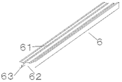
図4は、図3において、縦柱1に化粧柱としての縦枠6を被覆した状態の正面図である。図5は、図3のA−A線断面図であり、図6は、図5において、縦柱1に化粧柱としての縦枠6を被覆したものである。図7は、ここで使用する縦枠6の詳細を示したものであり、縦枠6の裏面側には、縦柱1を被覆するための略同形状の凹部を設けている。表面側には細溝63が設けられており、図4、図6に示すように縦柱1に縦枠6を被覆した後、細溝63からビス等を打ち込んで固定し、細溝部分63にカバー材(パッキン)61を充填することで、ビスを隠すと共に施工後の引戸の戸当りとしても使用ができる。縦枠6の下端部で、縦柱1を床面に固定している床固定金具12やアジャスター13が隠れるので、意匠性に優れた間仕切ユニットUが得られる。
FIG. 4 is a front view showing a state in which the
図8は収納棚Sの展示棚部分の背面(廊下側)にガラスを嵌め込む。ガラスの固定方法としては種々考えられるが、例えば、展示棚部分の廊下側端部に溝を設けてガラスを矢印のように一方からスライドさせ、定位置に配置した後、図9に示すように側板部押さえ部材92で横方向の溝を押さえ、天板裏側に天板部押さえ部材91で押さえることで、ガラスを固定する。なお、展示棚部分の棚板、仕切り板の位置に合わせて裏面のガラス上から飾り棒を両面テープで貼り付けることで、廊下側からでも見栄えよく展示物を見ることができる。
In FIG. 8, glass is fitted on the back surface (hallway side) of the display shelf portion of the storage shelf S. There are various methods for fixing the glass. For example, a groove is provided at the end of the hallway side of the display shelf, and the glass is slid from one side as shown by the arrow and placed at a fixed position, as shown in FIG. The glass is fixed by pressing the lateral groove with the side
以上説明したように、本発明は、ドア部分の縦枠を容易に交換することができる間仕切ユニットに関して有用である。 As described above, the present invention is useful for a partition unit in which the vertical frame of the door portion can be easily replaced.
U 床下空間
W 床上空間
D ドア設備
S 収納棚
1 縦柱
2 横柱(上枠)
3、3‘ 横柱(中鴨居)
4 天井固定桟
5 縦柱固定桟
6 縦枠
63 カバー材
U Underfloor space W Overfloor space D Door equipment
3, 3 'horizontal pillar (Nakamomoi)
4 Ceiling fixing bar 5 Vertical
Claims (3)
Priority Applications (1)
| Application Number | Priority Date | Filing Date | Title |
|---|---|---|---|
| JP2016084078A JP6875072B2 (en) | 2016-04-19 | 2016-04-19 | Partition unit |
Applications Claiming Priority (1)
| Application Number | Priority Date | Filing Date | Title |
|---|---|---|---|
| JP2016084078A JP6875072B2 (en) | 2016-04-19 | 2016-04-19 | Partition unit |
Publications (2)
| Publication Number | Publication Date |
|---|---|
| JP2017193855A true JP2017193855A (en) | 2017-10-26 |
| JP6875072B2 JP6875072B2 (en) | 2021-05-19 |
Family
ID=60154717
Family Applications (1)
| Application Number | Title | Priority Date | Filing Date |
|---|---|---|---|
| JP2016084078A Active JP6875072B2 (en) | 2016-04-19 | 2016-04-19 | Partition unit |
Country Status (1)
| Country | Link |
|---|---|
| JP (1) | JP6875072B2 (en) |
Cited By (4)
| Publication number | Priority date | Publication date | Assignee | Title |
|---|---|---|---|---|
| CN110872886A (en) * | 2018-08-30 | 2020-03-10 | 北新集团建材股份有限公司 | Buckle type keel assembly and wall body thereof |
| CN110872888A (en) * | 2018-08-30 | 2020-03-10 | 北新集团建材股份有限公司 | Clamping hook type keel assembly and wall thereof |
| CN110872880A (en) * | 2018-08-30 | 2020-03-10 | 北新集团建材股份有限公司 | Assembled wall body that trip was connected |
| CN110872887A (en) * | 2018-08-30 | 2020-03-10 | 北新集团建材股份有限公司 | Assembled wall body connected by buckling type keels |
Citations (3)
| Publication number | Priority date | Publication date | Assignee | Title |
|---|---|---|---|---|
| JPH0748889A (en) * | 1993-08-06 | 1995-02-21 | Hokuei:Kk | Wooden partition unit |
| JP2005009258A (en) * | 2003-06-20 | 2005-01-13 | Daiken Trade & Ind Co Ltd | Partition device |
| JP2005336972A (en) * | 2004-05-25 | 2005-12-08 | Morisuke Kodama | Opening frame |
-
2016
- 2016-04-19 JP JP2016084078A patent/JP6875072B2/en active Active
Patent Citations (3)
| Publication number | Priority date | Publication date | Assignee | Title |
|---|---|---|---|---|
| JPH0748889A (en) * | 1993-08-06 | 1995-02-21 | Hokuei:Kk | Wooden partition unit |
| JP2005009258A (en) * | 2003-06-20 | 2005-01-13 | Daiken Trade & Ind Co Ltd | Partition device |
| JP2005336972A (en) * | 2004-05-25 | 2005-12-08 | Morisuke Kodama | Opening frame |
Cited By (8)
| Publication number | Priority date | Publication date | Assignee | Title |
|---|---|---|---|---|
| CN110872886A (en) * | 2018-08-30 | 2020-03-10 | 北新集团建材股份有限公司 | Buckle type keel assembly and wall body thereof |
| CN110872888A (en) * | 2018-08-30 | 2020-03-10 | 北新集团建材股份有限公司 | Clamping hook type keel assembly and wall thereof |
| CN110872880A (en) * | 2018-08-30 | 2020-03-10 | 北新集团建材股份有限公司 | Assembled wall body that trip was connected |
| CN110872887A (en) * | 2018-08-30 | 2020-03-10 | 北新集团建材股份有限公司 | Assembled wall body connected by buckling type keels |
| CN110872886B (en) * | 2018-08-30 | 2021-12-28 | 北新集团建材股份有限公司 | Buckle type keel assembly and wall body thereof |
| CN110872888B (en) * | 2018-08-30 | 2021-12-28 | 北新集团建材股份有限公司 | Clamping hook type keel assembly and wall thereof |
| CN110872887B (en) * | 2018-08-30 | 2021-12-28 | 北新集团建材股份有限公司 | Assembled wall body connected by buckling type keels |
| CN110872880B (en) * | 2018-08-30 | 2022-01-07 | 北新集团建材股份有限公司 | Assembled wall body that trip was connected |
Also Published As
| Publication number | Publication date |
|---|---|
| JP6875072B2 (en) | 2021-05-19 |
Similar Documents
| Publication | Publication Date | Title |
|---|---|---|
| US6761004B2 (en) | Reconfigurable room partitioning system | |
| JP2017193855A (en) | Partition unit | |
| JP6902741B2 (en) | Joinery construction structure | |
| KR102493408B1 (en) | Blackboard assistant and Screen board system for writing installation method | |
| JP7025891B2 (en) | Moving partition device | |
| JP6837807B2 (en) | Partition panel device | |
| KR20170106850A (en) | Folding door structure | |
| US2660269A (en) | Closet and wall construction | |
| JP2016037750A (en) | Door device of earthquake-resistant partition device | |
| JP6873658B2 (en) | Partition panel device | |
| JP2014070370A (en) | Opening structure, and method for constructing opening | |
| RU188402U1 (en) | FACING COMMUNICATION MINE | |
| JP6425151B2 (en) | Joiner construction structure | |
| JP2017071947A (en) | Interior structure of sliding door fitting part | |
| JP2006161316A (en) | Slide material for mounting article and article mounting structure using the same | |
| WO2020158147A1 (en) | Frame device and installation structure therefor | |
| US2490259A (en) | Wall structure | |
| JP6751889B2 (en) | Mounting structure of frame for fittings | |
| JP2021055502A (en) | Panel device for partition and door device for partition using the same | |
| JP6269785B2 (en) | Opening structure and opening construction method | |
| US20190150613A1 (en) | Modular counter and cabinet system | |
| ES2328542B1 (en) | DOOR SHEET OF REMOVABLE PANELS FRAMED IN ALUMINUM PROFILE AND WITH INSULATION. | |
| JP4220437B2 (en) | Partition panel | |
| JP2020169556A (en) | Construction method of fitting | |
| JP2004324326A (en) | Wooden movable wall |
Legal Events
| Date | Code | Title | Description |
|---|---|---|---|
| A621 | Written request for application examination |
Free format text: JAPANESE INTERMEDIATE CODE: A621 Effective date: 20190228 |
|
| A977 | Report on retrieval |
Free format text: JAPANESE INTERMEDIATE CODE: A971007 Effective date: 20191226 |
|
| A131 | Notification of reasons for refusal |
Free format text: JAPANESE INTERMEDIATE CODE: A131 Effective date: 20200107 |
|
| A521 | Request for written amendment filed |
Free format text: JAPANESE INTERMEDIATE CODE: A523 Effective date: 20200305 |
|
| RD02 | Notification of acceptance of power of attorney |
Free format text: JAPANESE INTERMEDIATE CODE: A7422 Effective date: 20200305 |
|
| A131 | Notification of reasons for refusal |
Free format text: JAPANESE INTERMEDIATE CODE: A131 Effective date: 20200915 |
|
| A521 | Request for written amendment filed |
Free format text: JAPANESE INTERMEDIATE CODE: A523 Effective date: 20201110 |
|
| TRDD | Decision of grant or rejection written | ||
| A01 | Written decision to grant a patent or to grant a registration (utility model) |
Free format text: JAPANESE INTERMEDIATE CODE: A01 Effective date: 20210413 |
|
| A61 | First payment of annual fees (during grant procedure) |
Free format text: JAPANESE INTERMEDIATE CODE: A61 Effective date: 20210422 |
|
| R150 | Certificate of patent or registration of utility model |
Ref document number: 6875072 Country of ref document: JP Free format text: JAPANESE INTERMEDIATE CODE: R150 |
|
| R250 | Receipt of annual fees |
Free format text: JAPANESE INTERMEDIATE CODE: R250 |