JP2017193802A - Engagement tool for mask - Google Patents
Engagement tool for mask Download PDFInfo
- Publication number
- JP2017193802A JP2017193802A JP2016085601A JP2016085601A JP2017193802A JP 2017193802 A JP2017193802 A JP 2017193802A JP 2016085601 A JP2016085601 A JP 2016085601A JP 2016085601 A JP2016085601 A JP 2016085601A JP 2017193802 A JP2017193802 A JP 2017193802A
- Authority
- JP
- Japan
- Prior art keywords
- locking
- mask
- hole
- string
- tightening
- Prior art date
- Legal status (The legal status is an assumption and is not a legal conclusion. Google has not performed a legal analysis and makes no representation as to the accuracy of the status listed.)
- Granted
Links
Images


Classifications
-
- A—HUMAN NECESSITIES
- A41—WEARING APPAREL
- A41D—OUTERWEAR; PROTECTIVE GARMENTS; ACCESSORIES
- A41D13/00—Professional, industrial or sporting protective garments, e.g. surgeons' gowns or garments protecting against blows or punches
- A41D13/05—Professional, industrial or sporting protective garments, e.g. surgeons' gowns or garments protecting against blows or punches protecting only a particular body part
- A41D13/11—Protective face masks, e.g. for surgical use, or for use in foul atmospheres
- A41D13/1161—Means for fastening to the user's head
-
- A—HUMAN NECESSITIES
- A41—WEARING APPAREL
- A41D—OUTERWEAR; PROTECTIVE GARMENTS; ACCESSORIES
- A41D13/00—Professional, industrial or sporting protective garments, e.g. surgeons' gowns or garments protecting against blows or punches
- A41D13/05—Professional, industrial or sporting protective garments, e.g. surgeons' gowns or garments protecting against blows or punches protecting only a particular body part
- A41D13/11—Protective face masks, e.g. for surgical use, or for use in foul atmospheres
- A41D13/1107—Protective face masks, e.g. for surgical use, or for use in foul atmospheres characterised by their shape
- A41D13/1138—Protective face masks, e.g. for surgical use, or for use in foul atmospheres characterised by their shape with a cup configuration
-
- A—HUMAN NECESSITIES
- A62—LIFE-SAVING; FIRE-FIGHTING
- A62B—DEVICES, APPARATUS OR METHODS FOR LIFE-SAVING
- A62B18/00—Breathing masks or helmets, e.g. affording protection against chemical agents or for use at high altitudes or incorporating a pump or compressor for reducing the inhalation effort
- A62B18/02—Masks
-
- A—HUMAN NECESSITIES
- A62—LIFE-SAVING; FIRE-FIGHTING
- A62B—DEVICES, APPARATUS OR METHODS FOR LIFE-SAVING
- A62B18/00—Breathing masks or helmets, e.g. affording protection against chemical agents or for use at high altitudes or incorporating a pump or compressor for reducing the inhalation effort
- A62B18/08—Component parts for gas-masks or gas-helmets, e.g. windows, straps, speech transmitters, signal-devices
- A62B18/084—Means for fastening gas-masks to heads or helmets
Abstract
Description
本発明は、マスク用の係止具に関する。 The present invention relates to a locking device for a mask.
従来、マスクの締紐を係止するための係止具は、公知である。例えば、特許文献1には、横長矩形状であって、長さ方向において対向する両端部において、上下に位置する一対のフック部(上フック部と下フック部)が配置された係止具が開示されている。上下フック部は、締紐の上側部分と下側部分とが係止される係止孔と、それらを係止孔に案内するための案内溝とを有する。 Conventionally, a locking tool for locking a mask string is known. For example, Patent Document 1 discloses a locking tool having a horizontally long rectangular shape in which a pair of upper and lower hook portions (upper hook portion and lower hook portion) are arranged at both ends facing each other in the length direction. It is disclosed. The upper and lower hook portions have a locking hole in which the upper part and the lower part of the tightening string are locked, and a guide groove for guiding them to the locking hole.
特許文献1に開示のマスク用の係止具によれば、着用者の頭部の背面側に係止具を配置し、上下フック部の案内溝から案内して係止孔に締紐の上下側部分をそれぞれ係止させることによって、締紐の上下側部分が互いに分岐した状態が維持されるので、マスク本体の接顔部を着用者の顔面にフィットさせることができる。 According to the mask locking tool disclosed in Patent Document 1, the locking tool is disposed on the back side of the wearer's head, guided from the guide groove of the upper and lower hook portions, and the upper and lower ends of the laces in the locking hole. By locking the side portions, the state in which the upper and lower side portions of the laces are branched from each other is maintained, so that the face contact portion of the mask body can be fitted to the wearer's face.
しかしながら、ゴム紐状の締紐を上下フック部に係止したのみであるから、マスクの着用状態において、着用者が口を動かしたとき等において、締紐が上下フック部内において下方へ摺動して、位置ずれしてしまうおそれがある。一方、かかる位置ずれを防止するために、締紐の上方部分の引張力を比較的に大きくした場合には、該上方部分に当接する着用者の耳部の上側が擦れて違和感や痛みを感じるおそれがある。また、案内溝は、締紐が進入、退出可能な大きさであるので、締紐が上下フック部の係止孔に係止された状態において、その長さ調整をするために締紐を引っ張ったときに、案内溝を通って外部に抜け出てしまうおそれがある。 However, since the rubber string-like tightening string is only locked to the upper and lower hook parts, the tightening string slides downward in the upper and lower hook parts when the wearer moves his / her mouth while wearing the mask. May be displaced. On the other hand, in order to prevent such displacement, when the tensile force of the upper part of the lace is relatively large, the upper side of the wearer's ear that comes into contact with the upper part rubs and feels uncomfortable or painful. There is a fear. In addition, the guide groove has a size that allows the strap to enter and exit, so that when the strap is locked in the locking hole of the upper and lower hooks, the strap is pulled to adjust its length. There is a risk of slipping outside through the guide groove.
本発明は、従来の発明の改良であって、マスクの着用状態において、締紐の係止状態が維持され、かつ、位置ずれを抑制することのできるマスク用の係止具の提供を課題としている。 It is an object of the present invention to provide a mask locking device that is an improvement of the conventional invention and that can maintain the locked state of the tightening string and can suppress displacement when the mask is worn. Yes.
本発明は、縦方向と横方向とを有し、前記横方向へ延びる第1及び第2側縁と、前記縦方向へ延びる第1及び第2端縁とを含む横長薄板状のマスク用の係止具に関する。 The present invention is for a horizontally long thin plate-shaped mask having a vertical direction and a horizontal direction, and including first and second side edges extending in the horizontal direction and first and second end edges extending in the vertical direction. It relates to a locking tool.
本発明のマスク用の係止具は、前記マスクの一方の締紐を係脱可能に係止するための第1係止部と、前記第1係止部の前記第2端縁側に位置する、前記マスクの他方の締紐を予め挿通しておくための挿通孔を有する第2係止部とを含み、前記第1係止部は、前記第1側縁から延びる案内溝と、前記案内溝につながる第1係止孔とを有し、前記第2係止部は、前記挿通孔に連なりそれよりも外形の小さな第2係止孔を有し、前記第1係止孔と前記第2係止孔とが、前記横方向において互いに相反する方向へ向いている。 The locking device for a mask according to the present invention is positioned on the second end side of the first locking portion, and a first locking portion for locking one of the fastening straps of the mask so as to be detachable. A second locking portion having an insertion hole for inserting the other fastening string of the mask in advance, the first locking portion extending from the first side edge, and the guide A first locking hole connected to the groove, and the second locking portion includes a second locking hole that is continuous with the insertion hole and has a smaller outer shape than the first locking hole. The two locking holes face in directions opposite to each other in the lateral direction.
本発明の少なくとも一つの実施形態に係るマスク用の係止具は、第1係止部が第1側縁から延びる案内溝と、案内溝につながる第1係止孔とを有し、第2係止部が挿通孔に連なりそれよりも外形の小さな第2係止孔を有し、第1係止孔と第2係止孔とが、横方向において互いに相反する方向へ向いていることから、マスクの着用状態において、締紐が所要の締め付け強度を発揮してマスク本体を顔面に密接させるとともに、締紐が係止具から外れることなく、その位置が上下にずれるのを抑制することができる。 The locking device for a mask according to at least one embodiment of the present invention has a guide groove in which the first locking portion extends from the first side edge, a first locking hole connected to the guide groove, and a second The locking portion is connected to the insertion hole and has a second locking hole having a smaller outer shape, and the first locking hole and the second locking hole are oriented in directions opposite to each other in the lateral direction. In the wearing state of the mask, the tightening string exhibits the required tightening strength to bring the mask body into close contact with the face, and the position of the tightening string is prevented from shifting up and down without coming off the locking tool. it can.
図面は、本発明の特定の実施の形態を示し、発明の不可欠な構成ばかりでなく、選択的及び好ましい実施の形態を含む。
下記の実施の形態は、図1〜図7に示す係止具10に関し、発明の不可欠な構成ばかりでなく、選択的及び好ましい構成を含む。
The following embodiment relates to the
<第1実施形態>
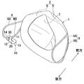
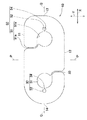
図1〜3を参照すると、マスク1は、マスク本体2とマスク本体2の両側縁から延出する環状の締紐3,4とを有し、係止具10は一対の締紐3,4を着用者の頭部の背面において互いに連結するために使用される。マスク本体2は、内部空間7を画成するようにカップ状に賦型された被覆部5と、被覆部5の外周縁部の後面側に接合された接顔部(接顔パッド)6とを有する。締紐3,4は、両端部がバックル8を介してマスク本体2の両側縁部に固定され、着用状態において、上下に分岐する上側部分3A,4Aと下側部分3B,4Bとを有する。
<First Embodiment>
1 to 3, the mask 1 has a
締紐3,4には、ストランド状のゴム紐等からなる紐状弾性体や平ゴム等の所要の厚さ寸法を有する帯状弾性体を使用することができる。マスク1の着用状態において、所要のフィット性やシール性が発揮される限りにおいて、マスク本体2は被覆部5のみから形成されていてもよいし、被覆部5は、カップ状に成型せずに、フィルター機能を有する複数の布や不織布を平面的又はそれらをプリーツ状に折り重ねて立体的に形成したものであってもよい。
The
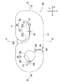
図2を参照すると、係止具10は、縦方向Y及び横方向Xと、縦方向Yの寸法を2等分する横断中心線Qと横方向Xの寸法を2等分する縦断中心線Pとを有する横長薄板状であって、横方向Xへ延びる第1及び第2側縁11,12と、縦方向Yへ延びる第1及び第2端縁13,14とを含む。第1及び第2側縁11、12とは、横方向Xへ直状に延びており、第1及び第2端縁13,14は、横方向Xの外側へ向かって凸曲した形状を有し、両側縁11,12及び両端縁13,14が互いに交差する隅部は、曲状を有する。また、第2端縁14の曲率は第1端縁13のそれよりも大きく、より大きく円弧状にカーブした形状を有する。ただし、後記の本願発明の効果を奏する限りにおいて、第1及び第2端縁13,14の曲率は同じであってもよいし、第1端縁13の曲率が第2端縁14のそれよりも大きくてもよく、それらの曲率は図示された態様に限定されるものではない。
Referring to FIG. 2, the locking
係止具10は、マスク1の一方の締紐3を係止するための第1係止部20と、第1係止部20の第2端縁14側に位置する、マスク1の他方の締紐4を予め挿通しておくための挿通孔31を有する第2係止部30とをさらに有する。第1係止部20は、第1側縁11から内方へ向かって延びる案内溝21と、案内溝につながる第1係止孔22とを有する。
The
第1係止部20の案内溝21は、第1側縁11から第1端縁13へ向かってカーブして延びる曲状部位21aと、曲状部位21aの終端から連なるように横断中心線Qに沿って横方向Xへ直状に延びる直状部位21bとを有する。案内溝21の曲状部位21aは内方へ向かうにつれて次第に幅狭となっており、第1側縁11その終端近傍(直状部位21bとの境界近傍)において最も幅狭となっている。直状部位21bの幅寸法W1は、曲状部位21aの終端の幅寸法と同じであって、ほぼ一定である。曲状部位21aのカーブの度合いや案内溝21の幅寸法は、係止具10の大きさや締紐3,4の幅寸法等によって適宜変更することができる。本実施形態において、案内溝21のうちの最も幅広部分、すなわち、第1側縁11を分離する離間部分の幅寸法(曲状部位21aの第1側縁11側の幅寸法)W5は、直状部位21bの幅寸法W1の少なくとも3倍以上である。
The
第2係止部30は、第2側縁12から内方へ延びて挿通孔31に連通する切り込み部33をさらに有する。切り込み部33は、第2側縁12側から内方へ向かって幅狭となり、挿通孔31側において僅かに第2端縁14側へカーブしている。挿通孔31は、第2端縁14側において頸部34を介して第2係止孔32に連通している。第2係止孔32は、円形であって、その直径は、挿通孔31よりも小さく、かつ、第1係止孔22とほぼ同じ大きさである。第1及び第2係止孔22,32は、締紐3,4が弾性変形された状態で係止される限りにおいて、楕円形、三角形、多角形等の各種公知の形状を有するものであってもよい。また、挿通孔31についても、締紐4が予め挿通される大きさを有する限りにおいて、楕円形、三角形、多角形等の各種公知の形状を採用することができる。
The
また、頸部34の幅寸法W2は、第2係止孔32の直径よりも小さくて、係止部20の案内溝21の直状部位21bの幅寸法W1とほぼ同じである。直状部位21bの幅寸法W1と頸部34の幅寸法W2とは、帯状弾性体からなる締紐3,4の幅寸法又は紐状弾性体からなる締紐3,4の直径よりも小さくて、締紐3,4が弾性変形しながら第1及び第2係止孔22,32へ向かって通過できる程度の大きさである。
Further, the width dimension W2 of the
第1係止部20の第1係止孔22は、直状部位21bと連通する円形の小孔であって、その直径は、直状部位21bの幅寸法W1よりも大きくなっている。また、第2係止孔32の直径は、第1係止孔22とほぼ同じであって、第1係止孔22と第2係止孔32とは、横断中心線Qに沿って、横方向において互いに相反する方向へ向いている。ここで、「第1係止孔22と第2係止孔32とが横方向Xにおいて相反する方向へ向いている」とは、第1及び第2係止部20,30において、第1及び第2係止孔22,32よりも幅狭の部分(第1係止部20においては直状部位21b、第2係止部30においては頸部34)から第1及び第2係止孔22,32へ向かう方向ベクトルF1,F2が横方向Xにおいて互いに相反することをいう。したがって、第1係止孔22と第2係止孔32とが横断中心線Q上ではなく、第1又は第2側縁11,12側へずれて位置している場合や案内溝21及び/又は頸部34の形状が図示している態様と異なるものであっても、第1係止孔22と第2係止孔32に関する方向ベクトルF1,F2が相反する限りにおいて、第1係止孔22と第2係止孔32とは横方向Xにおいて互いに相反するといえる。よって、例えば、第1係止部20の案内溝21が曲状部分21aを有さずに、縦断中心線Pに関して傾斜して第1側縁11から第1係止孔22まで延びる直状ラインであってもよいし、第2係止部30の切り込み部33が、第2側縁12から挿通孔31まで縦中心線Pへ向かって延びる直状ラインであってもよい。さらに、第2係止部30の切り込み部33は、第2側縁12からではなく、第1係止部20の案内溝21から挿通孔31へ直状又は曲状に延びていてもよい。
The
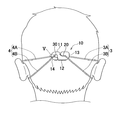
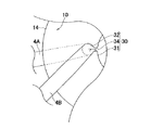
一方の締紐4は、マスク1の製造時において第2係止部30の挿通孔31に予め挿通されている。このように、予め締紐4が挿通孔31に挿通されていることによって、製造工程及び個包装袋からマスク1を取り出したときに、係止具10がマスク1から分離されることはなく、開封して使用する前に、係止具10を紛失してしまうおそれはない。図4及び図5を参照して、マスク1の着用操作について説明すると、まず、着用者はマスク本体2の接顔部6を顔面に宛がって、かかる状態を維持したまま一方の手で締紐4が挿通された係止具10を把持して頭部の背面側へ引っ張り、他方の手で締紐3を把持して頭部の背面側へ引っ張る。次に、締紐3を第1係止部20の案内溝21をガイドとして第1係止孔22へと誘導するように引っ張って、第1係止孔22へ係止させるとともに、挿通孔31に挿通された締紐4を第2端縁14側へ頸部34内をスライドさせるように移動させて第2係止孔32に係止させる。第1係止部20に案内溝21が形成されていることによって、締紐3を第1係止孔22へ容易に移動させることができ、また、第2係止部30において挿通孔31と第2係止孔32との間に幅狭の頸部34が位置することによって、それに沿って締紐4をスライドさせるだけで容易に第2係止孔32へ移動させることができるので、着用者が直接目視しなくても一連の操作を容易に行うことができる。締紐3,4が、それそれ、第1及び第2係止孔22、32に係止されて折り返されていることによって、上側部分3A,4Aと下側部分3B,4Bとに分岐される。このように、環状の締紐3,4を上下に分岐させて、上側部分3A,4Aを耳部の上側に引っ掛けるように引っ張り上げることによって、締紐3,4を安定的に耳部に掛け回すことができる。
One
例えば、第1係止孔22及び/又は第2係止孔32の方向ベクトルF1,F2が、縦方向Yへ向かう場合には、締紐3,4の引張力によるマスク本体2を顔面に密着させようとする力が十分に作用せずに、着用中にマスク本体2が顔面からずれ落ちてしまうおそれがある。本実施形態においては、第1係止孔22と第2係止孔32とは、横方向Xにおいて互いに相反する方向へ向いていることから、係止具10を介して締紐3,4どうしが横方向Xに引っ張り合って、所要の締め付け強度を発揮させることができる。
For example, when the direction vectors F1 and F2 of the
図6(a)は、帯状弾性体を使用した締紐を第1係止孔に係止させた状態における図、図6(b)は、帯状弾性体を使用した締紐の断面図、図6(c)は、紐状弾性体を使用した締紐3を第2係止孔22に係止させた状態における図、図6(d)は、紐状弾性体を使用した締紐3の断面図である。図6(a)〜(d)は、第1係止孔22に締紐3を係止させた状態を示しているが、本実施形態において、第1係止孔22と第2係止孔32とは同形同大であるので、第2係止孔32においても締紐4の係止態様は同様である。
FIG. 6A is a diagram showing a state in which a tightening string using a band-shaped elastic body is locked in the first locking hole. FIG. 6B is a cross-sectional view of the tightening string using the band-shaped elastic body. 6 (c) is a diagram in a state in which the tightening
図6(a),(b)を参照すると、締紐3(締紐4も同じ)として所定の幅寸法Rを有する平ゴム等の帯状弾性体を使用した場合において、第1係止孔22の内周囲長L1は、締紐3の幅寸法R1よりも小さくなっている。マスク1の着用時において、締紐3を第1係止部20に係止させるためには、第1側縁11側から案内溝21をガイドとして第1係止孔22へ向かって移動させる。このとき、第1係止孔22内において平ゴムからなる締紐3が丸められた状態で配置され、かつ、その幅寸法R1が内周囲長L1よりも大きいので、その一部が弾性変形して直状部位21bへ進入している。締紐3の幅寸法R1が第1係止孔22の内周囲長L1より小さい場合には、着用状態において、締紐3が丸められた状態で配置されても前後方向(紙面と直交する方向)へ移動してしまうおそれがあるが、幅寸法R1が内周囲長L1よりも大きくその一部が直状部位21bへ進入していることから、かかる移動が規制される。
Referring to FIGS. 6A and 6B, when a belt-like elastic body such as a flat rubber having a predetermined width R is used as the fastening string 3 (the
図6(c),(d)を参照すると、締紐3(締紐4も同じ)としてストランド状の紐ゴム等の紐状弾性体を使用した場合において、第1係止孔22の内周囲長L1は、締紐3の円形断面の外周寸法(外周囲長)R2よりも小さくなっている。したがって、マスク1を着用するために第1係止孔22に締紐3を配置した状態において、締紐3の一部が弾性変形して直状部位21bに進入するので、図6(a)の態様と同様に、締紐3の前後方向における移動が規制される。このように、締紐3,4が平ゴム等の帯状弾性体から形成されている場合にはその幅寸法R1、ゴム紐等の紐状弾性体から形成されている場合にはその外周寸法R2が、第1及び第2係止孔22,32の内周囲長L1よりも大きいことによって、マスク1を着用したときに、締紐3,4の移動が規制されて、締紐3,4が位置ずれするのを抑制することができる。また、着用状態において、締紐3,4の上側部分3A,4Aと下側部分3B,4Bとが同じ張力を有する場合には、上側部分3A,4Aが耳部に比較的に強く当たって刺激を与えるおそれがあるところ、締紐3,4が弾性変形されて適度な抵抗が生じることによって、上側部分3A,4Aと下側部分3B,4Bとが同じ張力にならないように、すなわち、上側部分3A,4Aの張力(テンション)を下側部分3B,4Bの張力よりも小さくなるようにすることができる。
6 (c) and 6 (d), when a string-like elastic body such as a strand-like string rubber is used as the tightening string 3 (the same as the tightening string 4), the inner periphery of the
本実施形態に係るマスク1のように、締紐3,4を上下に折り返して耳部に掛け回す場合には、通常、マスク1を着用する前に、頭部の寸法に合わせて上側部分3A,4Aと下側部分3B,4Bとの長さ調整を行った状態で着用する。すなわち、上側部分3A,4Aの長さ寸法が比較的に短いと、それを引張上げて耳部に引っ掛けたときに擦れて着用者が痛みを感じることがあるので、上側部分3A,4Aを下側部分3B,4Bに対して相対的に長くなるように事前に調整した状態で着用する。また、既述のとおり、上側部分3A,4Aの張力が下側部分3B,4Bと同じ場合には耳部に痛みを感じることあるので、上側部分3A,4Aの張力が小さくなるように調整して着用しても、着用している間に上側部分3A,4Aの張力と下側部分3B,4Bの張力とが同じ大きさになってしまうことがある。
When the
本実施形態に係るマスク1では、締紐3,4が帯状弾性体と紐状弾性体とのいずれかから形成されている場合であっても、第1及び第2係止孔22,32に係止されたときに、その一部が弾性変形して幅狭部分に進入するので、一旦係止されてしまえば、不用意に前後方向へ移動することはない。したがって、予め調整していた締紐3,4の長さ寸法が、着用中に変化することを抑制することができる。ただし、締紐3,4の移動が完全に規制される場合には、着用後に、着用者自らが上側部分3A,4Aと下側部分3B,4Bとの長さ寸法を微調整することができない。したがって、締紐3,4を所要の力で上方又は下方へ引っ張ることによって締紐3,4が移動できるだけの緩みのある状態で係止されていることが好ましい。かかる係止を実現するために、締紐3,4が帯状弾性体から形成されている場合には幅寸法R1又は紐状弾性体から形成されている場合には外周寸法がR2、第1及び第2係止孔22,32の内周囲長L1の150%の大きさであることが好ましい。このように、本実施形態に係る係止具10によれば、締紐3,4に所要の抵抗が負荷されることによって前後方向への移動が規制されるので、会話のときの口部の動き程度では、調整した上下側部分3A,3B,4A,4Bの張力が変更されることはない。また、着用者が自らの手で操作することによって自由に上下側部分3A,3B,4A,4Bの長さを容易に調整することができるので、仮に着用中にそれらの張力が変更されたとしても、適度な張力に戻すことができる。
In the mask 1 according to the present embodiment, the first and second locking holes 22 and 32 are formed even when the
再び、図2を参照すると、第2係止部30の切り込み部33の挿通孔31の近傍に位置する部分の幅寸法W4は、頸部34の幅寸法W2よりも小さく、また、案内溝21の直状部位21bの幅寸法W1よりも小さくなっている。また、直状部位21bの幅寸法W1と頸部34の幅寸法W2とは、帯状弾性体又は紐状弾性体からなる締紐3,4を弾性変形させながら第1係止孔22へ向かって通過させることができる程度の大きさであるのに対し、切り込み部33の幅寸法W4は、弾性変形させても締紐3,4が通過できない大きさであることが好ましい。締紐3は、予め挿通孔31に挿通されていることから、切り込み部33の幅寸法W4をこのように比較的に小さくすることによって、締紐3が係止具10から外れるのを防止することができる。一方、第1係止部20では、案内溝21が締紐4が通過できる程度の大きさを有しているが、切り込み部33に比して第2係止孔22へ向かって大きくカーブしていることから、第1係止孔22の係止が解除されて締紐4が第1側縁側へ移動しても、簡単に係止具10から外れにくくなっている。
Referring to FIG. 2 again, the width dimension W4 of the portion located in the vicinity of the
<第2実施形態>
図7は、第2実施形態に係る係止具10の平面図である。本実施形態に係る係止具10は、第1実施形態に係る係止具10と基本的構成が同じであって、相違する点についてのみ以下に説明する。
Second Embodiment
FIG. 7 is a plan view of the
図7を参照すると、本実施形態に係る係止具10においては、第1係止部50が第2係止部30と同形であって、第1係止部50の案内溝51は、第1側縁11から内方へ延びる第1部分51aと連通する、第2係止部30の挿通孔31と同形同大の第2部分51bとを有する。第1部分51aは、第2部分51b側において僅かに第1端縁13側へカーブしている。第2部分51bは、第1端縁13側において頸部54を介して第1係止孔22に連通している。かかる形状を有する係止具10においては、マスク1の使用前に、第2係止部30に締紐3が予め挿通されるとともに、第1係止部50の第2部分51bに締紐4が予め挿通されていてもよい。また、着用するときに、第1係止部50の第1部分51aをガイドとして締紐4を通過させてもよい。
Referring to FIG. 7, in the
係止具10は、軟質又は硬質の合成樹脂から形成されるほかに、所要の弾性を発揮する限りにおいて、紙製又は金属製であってもよい。また、その外形についても、第1係止部20,50と第2係止部30とが横方向Xにおいて並んで位置する限りにおいて、隅部が曲状ではなく先鋭状であってもよく、使用するマスク1の大きさに合わせて、縦方向Y及び横方向Xの寸法や厚さ寸法を適宜調整することができる。さらに、係止具10に意匠性を付与するために、有彩色に着色されていてもよいし、絵柄、記号、文字、商品ロゴ等の各種の意匠要素が配置されていてもよい。
In addition to being formed of a soft or hard synthetic resin, the locking
以上に記載した本発明に関する開示は、以下の事項に整理することができる。 The disclosure related to the present invention described above can be summarized as follows.
縦方向と横方向とを有し、前記横方向へ延びる第1及び第2側縁と、前記縦方向へ延びる第1及び第2端縁とを含む横長薄板状のマスク用の係止具であって、前記マスクの一方の締紐を係脱可能に係止するための第1係止部と、前記第1係止部の前記第2端縁側に位置する、前記マスクの他方の締紐を予め挿通しておくための挿通孔を有する第2係止部とを含み、前記第1係止部は、前記第1側縁から延びる案内溝と、前記案内溝につながる第1係止孔とを有し、前記第2係止部は、前記挿通孔に連なりそれよりも外形の小さな第2係止孔を有し、前記第1係止孔と前記第2係止孔とが、前記横方向において互いに相反する方向へ向いている。 A locking device for a horizontally long thin plate-like mask having a vertical direction and a horizontal direction, and including first and second side edges extending in the horizontal direction and first and second end edges extending in the vertical direction. A first locking portion for releasably locking one of the fastening straps of the mask, and the other fastening strap of the mask positioned on the second end edge side of the first locking portion. A second locking portion having an insertion hole for inserting the first locking portion in advance, the first locking portion extending from the first side edge, and a first locking hole connected to the guide groove The second locking portion has a second locking hole that is continuous with the insertion hole and has a smaller outer shape, and the first locking hole and the second locking hole are In the lateral direction, the directions are opposite to each other.
上記段落0032に開示の本発明は、少なくとも下記の実施の形態を含むことができる。該実施の形態は、分離して又は互いに組み合わせて採択することができる。
(1)前記第1係止部の前記案内溝は、前記第1側縁から内方へ延びる第1部分と、前記第1係止孔に連なる、前記第1係止孔よりも外形の大きい円形状の第2部分とを有する。
(2)前記締紐が、帯状弾性体から形成されており、前記締紐の幅寸法が前記第1及び第2係止孔の内周囲長よりも大きい。
(3)前記締紐は、紐状弾性体から形成されており、前記締紐の外周寸法が前記第1及び第2係止孔の内周囲長よりも大きい。
(4) 前記第2係止部は、前記挿通孔へつながる切り込み部を有し、前記切り込み部の前記挿通孔の近傍に位置する部分の幅寸法は、前記頸部の幅寸法よりも小さい。
The present invention disclosed in the above paragraph 0032 can include at least the following embodiments. The embodiments can be adopted separately or in combination with each other.
(1) The guide groove of the first locking portion has a first portion extending inward from the first side edge and a larger outer shape than the first locking hole, which is continuous with the first locking hole. A second portion having a circular shape.
(2) The tightening string is formed of a belt-like elastic body, and the width dimension of the tightening string is larger than the inner peripheral lengths of the first and second locking holes.
(3) The tightening string is formed of a string-like elastic body, and an outer peripheral dimension of the tightening string is larger than inner peripheries of the first and second locking holes.
(4) The second locking portion has a cut portion connected to the insertion hole, and a width dimension of a portion of the cut portion located in the vicinity of the insertion hole is smaller than a width dimension of the neck portion.
1 マスク
3 締紐
4 締紐
10 係止具
11 第1側縁
12 第2側縁
13 第1端縁
14 第2端縁
20 第1係止部
21 案内溝
22 第1係止孔
30 第2係止部
31 挿通孔
32 第2係止孔
33 切り込み部
50 第1係止部
51 案内溝
51a 第1部分
51b 第2部分
L1 第1及び第2係止孔の内周囲長
R1 帯状弾性体からなる締紐の幅寸法
R2 紐状弾性体からなる締紐の外周囲長
X 横方向
Y 縦方向
DESCRIPTION OF SYMBOLS 1
Claims (5)
マスクの一方の締紐を係脱可能に係止するための第1係止部と、前記第1係止部の前記第2端縁側に位置する、前記マスクの他方の締紐を予め挿通しておくための挿通孔を有する第2係止部とを含み、
前記第1係止部は、前記第1側縁から延びる案内溝と、前記案内溝につながる第1係止孔とを有し、
前記第2係止部は、前記挿通孔に連なりそれよりも外形の小さな第2係止孔を有し、前記第1係止孔と前記第2係止孔とが、前記横方向において互いに相反する方向へ向いていることを特徴とする係止具。 A mask for a horizontally long thin plate having a vertical direction and a horizontal direction and including first and second side edges extending in the horizontal direction and first and second end edges extending in the vertical direction. And
A first locking portion for releasably locking one of the tightening straps of the mask, and the other tightening strap of the mask positioned on the second end edge side of the first locking portion are inserted in advance. A second locking portion having an insertion hole for keeping
The first locking portion has a guide groove extending from the first side edge, and a first locking hole connected to the guide groove,
The second locking portion has a second locking hole that is continuous with the insertion hole and has a smaller outer shape, and the first locking hole and the second locking hole are mutually opposite in the lateral direction. A locking tool characterized by being directed in a direction to perform.
The said 2nd latching | locking part has a notch part connected to the said penetration hole, The width dimension of the part located in the vicinity of the said penetration hole of the said notch part is smaller than the width dimension of the said neck part. 4. The locking tool according to any one of 4 above.
Priority Applications (8)
| Application Number | Priority Date | Filing Date | Title |
|---|---|---|---|
| JP2016085601A JP6344802B2 (en) | 2016-04-21 | 2016-04-21 | Mask with locking tool |
| KR1020187030565A KR102037020B1 (en) | 2016-04-21 | 2017-04-13 | Mask with gutter |
| US16/095,343 US10638802B2 (en) | 2016-04-21 | 2017-04-13 | Mask provided with latch |
| MYPI2018703773A MY170359A (en) | 2016-04-21 | 2017-04-13 | Mask provided with latch |
| CN201780024042.0A CN109068773B (en) | 2016-04-21 | 2017-04-13 | Mask with locking piece |
| CA3020674A CA3020674C (en) | 2016-04-21 | 2017-04-13 | Mask provided with latch |
| EP17785884.2A EP3446582B1 (en) | 2016-04-21 | 2017-04-13 | Mask provided with latch |
| PCT/JP2017/015059 WO2017183545A1 (en) | 2016-04-21 | 2017-04-13 | Mask provided with latch |
Applications Claiming Priority (1)
| Application Number | Priority Date | Filing Date | Title |
|---|---|---|---|
| JP2016085601A JP6344802B2 (en) | 2016-04-21 | 2016-04-21 | Mask with locking tool |
Publications (3)
| Publication Number | Publication Date |
|---|---|
| JP2017193802A true JP2017193802A (en) | 2017-10-26 |
| JP2017193802A5 JP2017193802A5 (en) | 2018-06-07 |
| JP6344802B2 JP6344802B2 (en) | 2018-06-20 |
Family
ID=60116063
Family Applications (1)
| Application Number | Title | Priority Date | Filing Date |
|---|---|---|---|
| JP2016085601A Active JP6344802B2 (en) | 2016-04-21 | 2016-04-21 | Mask with locking tool |
Country Status (8)
| Country | Link |
|---|---|
| US (1) | US10638802B2 (en) |
| EP (1) | EP3446582B1 (en) |
| JP (1) | JP6344802B2 (en) |
| KR (1) | KR102037020B1 (en) |
| CN (1) | CN109068773B (en) |
| CA (1) | CA3020674C (en) |
| MY (1) | MY170359A (en) |
| WO (1) | WO2017183545A1 (en) |
Cited By (3)
| Publication number | Priority date | Publication date | Assignee | Title |
|---|---|---|---|---|
| JP6955289B1 (en) * | 2020-12-14 | 2021-10-27 | 尚宏 篠本 | Mask strap |
| KR20220008002A (en) * | 2020-07-13 | 2022-01-20 | 왕용진 | Lamp structure for facial protective guard |
| JP2022102019A (en) * | 2020-12-25 | 2022-07-07 | 直大 杉山 | Mask attachment support band |
Families Citing this family (12)
| Publication number | Priority date | Publication date | Assignee | Title |
|---|---|---|---|---|
| KR102121619B1 (en) * | 2018-04-10 | 2020-06-10 | 김회철 | Children's wearable earring straps for mask |
| KR20210119813A (en) | 2020-03-25 | 2021-10-06 | 주식회사 엠팩플러스 | strap band for mask |
| DE102020108414B4 (en) | 2020-03-26 | 2023-02-16 | Pfanner Schutzbekleidung Gmbh | protective face mask |
| USD928304S1 (en) | 2020-05-07 | 2021-08-17 | Chi Wai Philip Yu | Face mask with adjustable ear loops |
| IT202000011122A1 (en) * | 2020-05-18 | 2020-08-18 | Luca Giacomino | Elastic stretchers for mask protect mouth and nose |
| US11564426B2 (en) | 2020-06-18 | 2023-01-31 | Jmdm Holdings Llc | Facial covering system |
| KR102232316B1 (en) | 2020-07-25 | 2021-03-25 | 박동열 | Hook band for mask |
| KR102291330B1 (en) * | 2020-12-31 | 2021-08-18 | 서한나 | Disposable mask |
| US20220211124A1 (en) * | 2021-01-07 | 2022-07-07 | Mark Hunter | Sanitary Face Mask Assembly |
| USD997345S1 (en) * | 2021-01-27 | 2023-08-29 | Katharos Laboratories, Llc | Tensioning device for a face mask |
| USD957633S1 (en) * | 2021-03-01 | 2022-07-12 | DFund Limited | Head support for a face mask |
| USD1004074S1 (en) * | 2021-03-31 | 2023-11-07 | Honeywell International Inc. | Strap tab |
Citations (5)
| Publication number | Priority date | Publication date | Assignee | Title |
|---|---|---|---|---|
| JP2003320041A (en) * | 2002-05-02 | 2003-11-11 | Shigematsu Works Co Ltd | Mask |
| JP2005152229A (en) * | 2003-11-25 | 2005-06-16 | Msa Japan Kk | Clip for mask |
| JP2008049194A (en) * | 2007-11-09 | 2008-03-06 | Koken Ltd | Disposable type dust mask |
| JP2012090682A (en) * | 2010-10-25 | 2012-05-17 | Morito Co Ltd | Cord adjuster |
| JP2013252339A (en) * | 2012-06-08 | 2013-12-19 | Planet:Kk | Fastening implement for mask |
Family Cites Families (13)
| Publication number | Priority date | Publication date | Assignee | Title |
|---|---|---|---|---|
| US696196A (en) * | 1901-12-19 | 1902-03-25 | Max Rubin | Suspension-clasp. |
| JP3413585B2 (en) | 1997-01-22 | 2003-06-03 | 山本光学株式会社 | Length adjustment member of mask lace |
| JP2000140139A (en) | 1998-11-04 | 2000-05-23 | Takehara Nobuaki | Disposable simplified mask and mask frame |
| JP3200050B2 (en) | 1999-07-09 | 2001-08-20 | 博 安永 | Surgical suture stapler |
| KR200249515Y1 (en) | 2001-07-03 | 2001-11-16 | 이상원 | Mask |
| KR100844203B1 (en) | 2007-11-01 | 2008-07-04 | 이상원 | Mask for possible to control of length |
| JP5555058B2 (en) * | 2010-06-04 | 2014-07-23 | ミドリ安全株式会社 | Mask string length adjuster and mask |
| JP2012016516A (en) * | 2010-07-09 | 2012-01-26 | Midori Anzen Co Ltd | Mask tightening string length adjuster, and mask |
| KR20130000250U (en) * | 2011-07-01 | 2013-01-09 | (주)이지스 | The Dust Respirator |
| US9408424B2 (en) * | 2013-01-10 | 2016-08-09 | 3M Innovative Properties Company | Filtering face-piece respirator having a face seal comprising a water-vapor-breathable layer |
| JP2015093036A (en) | 2013-11-12 | 2015-05-18 | 也人 竹内 | Mask stopper |
| CN106794366A (en) | 2014-09-25 | 2017-05-31 | 北村光造 | Health gauze mask |
| JP3200050U (en) * | 2015-07-10 | 2015-10-01 | ホークアイ株式会社 | Mask holder |
-
2016
- 2016-04-21 JP JP2016085601A patent/JP6344802B2/en active Active
-
2017
- 2017-04-13 EP EP17785884.2A patent/EP3446582B1/en active Active
- 2017-04-13 CN CN201780024042.0A patent/CN109068773B/en active Active
- 2017-04-13 KR KR1020187030565A patent/KR102037020B1/en active IP Right Grant
- 2017-04-13 WO PCT/JP2017/015059 patent/WO2017183545A1/en active Application Filing
- 2017-04-13 US US16/095,343 patent/US10638802B2/en active Active
- 2017-04-13 MY MYPI2018703773A patent/MY170359A/en unknown
- 2017-04-13 CA CA3020674A patent/CA3020674C/en active Active
Patent Citations (5)
| Publication number | Priority date | Publication date | Assignee | Title |
|---|---|---|---|---|
| JP2003320041A (en) * | 2002-05-02 | 2003-11-11 | Shigematsu Works Co Ltd | Mask |
| JP2005152229A (en) * | 2003-11-25 | 2005-06-16 | Msa Japan Kk | Clip for mask |
| JP2008049194A (en) * | 2007-11-09 | 2008-03-06 | Koken Ltd | Disposable type dust mask |
| JP2012090682A (en) * | 2010-10-25 | 2012-05-17 | Morito Co Ltd | Cord adjuster |
| JP2013252339A (en) * | 2012-06-08 | 2013-12-19 | Planet:Kk | Fastening implement for mask |
Cited By (4)
| Publication number | Priority date | Publication date | Assignee | Title |
|---|---|---|---|---|
| KR20220008002A (en) * | 2020-07-13 | 2022-01-20 | 왕용진 | Lamp structure for facial protective guard |
| KR102444564B1 (en) * | 2020-07-13 | 2022-09-19 | 왕용진 | Lamp structure for facial protective guard |
| JP6955289B1 (en) * | 2020-12-14 | 2021-10-27 | 尚宏 篠本 | Mask strap |
| JP2022102019A (en) * | 2020-12-25 | 2022-07-07 | 直大 杉山 | Mask attachment support band |
Also Published As
| Publication number | Publication date |
|---|---|
| US10638802B2 (en) | 2020-05-05 |
| KR102037020B1 (en) | 2019-10-25 |
| CN109068773A (en) | 2018-12-21 |
| JP6344802B2 (en) | 2018-06-20 |
| EP3446582A1 (en) | 2019-02-27 |
| CA3020674A1 (en) | 2017-10-26 |
| WO2017183545A1 (en) | 2017-10-26 |
| EP3446582A4 (en) | 2019-02-27 |
| EP3446582B1 (en) | 2020-05-20 |
| US20190133219A1 (en) | 2019-05-09 |
| KR20180121659A (en) | 2018-11-07 |
| CA3020674C (en) | 2019-11-12 |
| CN109068773B (en) | 2019-12-31 |
| MY170359A (en) | 2019-07-24 |
Similar Documents
| Publication | Publication Date | Title |
|---|---|---|
| JP6344802B2 (en) | Mask with locking tool | |
| JP2017193802A5 (en) | ||
| CN107105803A (en) | For adjust band length buckle and including the buckled respirator | |
| KR20070071962A (en) | A mask with the length-control ear protector | |
| JP2012016516A (en) | Mask tightening string length adjuster, and mask | |
| JPH11206896A (en) | Face mask with wearing bands and its manufacturing | |
| KR200442308Y1 (en) | Necktie | |
| TWM544812U (en) | Rope tail positioning buckle | |
| US10716719B2 (en) | Diaper fastener | |
| JP2010000113A (en) | Golf glove | |
| JP6957124B1 (en) | Face shield | |
| JP3231255U (en) | Mask with neck strap | |
| CN215270736U (en) | Mask structure | |
| JP2018172837A (en) | Simply attachable obi | |
| JP3139188U (en) | Safety hood clasp | |
| JP3191923U (en) | Without crest | |
| JP2022113088A (en) | Mask strap fastener and mask strap | |
| JP3204893U (en) | Clothing with shoulder strap | |
| JP3112774U (en) | Facial muscle training equipment | |
| JP5121507B2 (en) | Swimwear waistband end member, waistband and swimsuit for swimming | |
| JP2021001412A (en) | belt | |
| JP2022120302A (en) | Posture correction implement | |
| JP3141348U (en) | Loop tie | |
| JP3120589U (en) | Jewelery locking structure, yukata belt and bellows using this | |
| JP5762178B2 (en) | Buckle with belt and helmet |
Legal Events
| Date | Code | Title | Description |
|---|---|---|---|
| A521 | Request for written amendment filed |
Free format text: JAPANESE INTERMEDIATE CODE: A523 Effective date: 20180416 |
|
| A621 | Written request for application examination |
Free format text: JAPANESE INTERMEDIATE CODE: A621 Effective date: 20180416 |
|
| A871 | Explanation of circumstances concerning accelerated examination |
Free format text: JAPANESE INTERMEDIATE CODE: A871 Effective date: 20180416 |
|
| A975 | Report on accelerated examination |
Free format text: JAPANESE INTERMEDIATE CODE: A971005 Effective date: 20180420 |
|
| TRDD | Decision of grant or rejection written | ||
| A01 | Written decision to grant a patent or to grant a registration (utility model) |
Free format text: JAPANESE INTERMEDIATE CODE: A01 Effective date: 20180516 |
|
| A61 | First payment of annual fees (during grant procedure) |
Free format text: JAPANESE INTERMEDIATE CODE: A61 Effective date: 20180517 |
|
| R150 | Certificate of patent or registration of utility model |
Ref document number: 6344802 Country of ref document: JP Free format text: JAPANESE INTERMEDIATE CODE: R150 |
|
| R250 | Receipt of annual fees |
Free format text: JAPANESE INTERMEDIATE CODE: R250 |
|
| R250 | Receipt of annual fees |
Free format text: JAPANESE INTERMEDIATE CODE: R250 |
|
| R250 | Receipt of annual fees |
Free format text: JAPANESE INTERMEDIATE CODE: R250 |