JP3141348U - Loop tie - Google Patents

Loop tie Download PDF

Info

Publication number
JP3141348U
JP3141348U JP2008000828U JP2008000828U JP3141348U JP 3141348 U JP3141348 U JP 3141348U JP 2008000828 U JP2008000828 U JP 2008000828U JP 2008000828 U JP2008000828 U JP 2008000828U JP 3141348 U JP3141348 U JP 3141348U
Authority
JP
Japan
Prior art keywords
loop
screw
decorative fastener
main body
decorative
Prior art date
Legal status (The legal status is an assumption and is not a legal conclusion. Google has not performed a legal analysis and makes no representation as to the accuracy of the status listed.)
Expired - Fee Related
Application number
JP2008000828U
Other languages
Japanese (ja)
Inventor
忠彦 徳永
Original Assignee
株式会社シーティー三愛
Priority date (The priority date is an assumption and is not a legal conclusion. Google has not performed a legal analysis and makes no representation as to the accuracy of the date listed.)
Filing date
Publication date
Application filed by 株式会社シーティー三愛 filed Critical 株式会社シーティー三愛
Priority to JP2008000828U priority Critical patent/JP3141348U/en
Application granted granted Critical
Publication of JP3141348U publication Critical patent/JP3141348U/en
Anticipated expiration legal-status Critical
Expired - Fee Related legal-status Critical Current

Links

Images

Abstract

【課題】ループタイとして、金属製の索体でも確実に装飾留め具に固定でき、その固定と解除の操作を極めて簡単に行え、構造的に簡素で製作容易なものを提供する。
【解決手段】首掛け用のループL1を形成する索体1と、索体1を挿通してループL1を拡縮する装飾留め具2とからなり、装飾留め具2の本体20の裏面側にネジ軸3が突設され、ネジ軸3に螺合するネジ板4の締め付けにより、ネジ板4と本体20との間で索体1を挟着固定するように構成されてなる。
【選択図】図2
Provided is a loop tie that can be securely fixed to a decorative fastener even with a metal cable body, and can be fixed and released very easily, and is structurally simple and easy to manufacture.
SOLUTION: A rope body 1 that forms a loop L1 for hanging around a neck and a decorative fastener 2 that is inserted through the rope body 1 and expands and contracts the loop L1, and a screw on the back side of a main body 20 of the decorative fastener 2. The shaft 3 is provided so as to be clamped and fixed between the screw plate 4 and the main body 20 by tightening the screw plate 4 screwed to the screw shaft 3.
[Selection] Figure 2

Description

本考案は、首掛け用のループを形成する索体と、この索体を挿通して前記ループを拡縮する装飾留め具とからなるループタイに関する。   The present invention relates to a loop tie comprising a rope forming a loop for hanging around the neck, and a decorative fastener that extends through the rope through the rope.

ループタイは、旧来では主として年配の男性がワイシャツ等の着用時にネクタイ代わりに使用していたが、近年では老若男女を問わず、またワイシャツ等に限らず、タートルネックのセーターに合わせたり、ネックレスのように直に首に掛けたり、お洒落な装飾として多用されつつある。   Loop ties have traditionally been used mainly by older men instead of ties when wearing shirts, etc. It can be hung directly on the neck or used as a stylish decoration.

しかして、通常のループタイでは、首掛け用のループを形成する索体として糸で編んだ紐を用い、この紐を種々の装飾形状及び材質の装飾留め具に挿通しており、そのループを一定サイズに保つ手段として、挿通部の摩擦抵抗を利用する方式(特許文献1)や、該装飾留め具の裏面側に設けたバネ式の挟着金具を利用する方式(特許文献2)が一般的に採用されている。
実用新案登録第3043618号 特開平10−5012号公報
Thus, in a normal loop tie, a string knitted with a thread is used as a rope forming a loop for a neck, and the string is inserted into decorative fasteners of various decorative shapes and materials, and the loop is fixed. As means for maintaining the size, a method using the frictional resistance of the insertion portion (Patent Document 1) and a method using a spring-type clamping metal fitting provided on the back side of the decorative fastener (Patent Document 2) are common. Has been adopted.
Utility model registration No. 3043618 Japanese Patent Laid-Open No. 10-5012

ところで、近年のループタイでは、その装飾性をより高めるために、ループを形成する索体として、一般的な糸で編んだ紐に代えて様々な形態のチェーン等の金属製のものを用いることが多くなっている。しかるに、このような金属製の索体は圧縮性がない上に硬く滑り易いため、従来の挿通部の摩擦抵抗による係止方式やバネ式の挟着金具による係止方式では、装飾留め具に確実に固定できず、使用中に加わる僅かな引張力や振動によって簡単に係止位置がずれてしまい、ループの緩みで体裁が悪くなるという難点があった。   By the way, in recent loop ties, in order to further enhance the decoration, it is possible to use metal items such as chains of various forms instead of the string knitted with a general thread as the rope forming the loop. It is increasing. However, such a metal cable body is not compressible and hard and slippery. Therefore, the conventional locking method using frictional resistance of the insertion portion and the locking method using spring-type clamps are used for decorative fasteners. There is a problem in that it cannot be fixed securely, and the locking position is easily shifted by a slight tensile force or vibration applied during use, and the appearance is deteriorated due to looseness of the loop.

本考案は、上述の情況に鑑み、ループタイとして、金属製の索体を用いたものでも確実に装飾留め具に固定できると共に、その固定と解除の操作を極めて簡単に行え、且つ構造的に簡素で製作容易なものを提供することを目的としている。   In view of the above situation, the present invention can reliably fix a loop tie using a metal cable body to a decorative fastener, and can perform fixing and releasing operations very easily and structurally simple. The purpose is to provide an easy-to-manufacture product.

上記課題を解決するための手段を、後述する実施形態の参照符号を付して説明すると、請求項1の考案に係るループタイは、首掛け用のループL1を形成する索体1と、この索体1を挿通してループL1を拡縮する装飾留め具2とからなり、該装飾留め具2の本体20の裏面側にネジ軸3が突設されると共に、該ネジ軸3に螺合するネジ板4を有し、このネジ板4の締め付けによって当該ネジ板4と本体20との間で前記挿通した索体1を挟着固定するように構成されてなる。   Means for solving the above problems will be described with reference numerals in the embodiments described later. A loop tie according to the invention of claim 1 includes a cable body 1 that forms a loop L1 for necking, and this cable tie. A decorative fastener 2 that extends through the body 1 and expands and contracts the loop L1 is provided. A screw shaft 3 projects from the back side of the main body 20 of the decorative fastener 2 and is screwed into the screw shaft 3 It has a plate 4, and is configured to clamp and fix the inserted cable body 1 between the screw plate 4 and the main body 20 by tightening the screw plate 4.

請求項2の考案は、上記請求項1のループタイにおいて、装飾留め具2の本体20とネジ板4の互いの対向面の少なくとも一方側に、軟質ないし半硬質の高分子層5A,5Bが形成されてなる構成としている。   The invention of claim 2 is the loop tie of claim 1, wherein soft or semi-rigid polymer layers 5A and 5B are formed on at least one side of the opposing surfaces of the main body 20 and the screw plate 4 of the decorative fastener 2. It is set as the structure which is made.

請求項3の考案は、上記請求項1又は2のループタイにおいて、索体1が金属製である構成としている。   The invention of claim 3 is the loop tie of claim 1 or 2, wherein the cord body 1 is made of metal.

請求項4の考案は、上記請求項1〜3のいずれかのループタイにおいて、装飾留め具2の本体20の裏面側の上下部に2条の索体1を並行して挿通させる挿通ガイド部6A,6Bが形成され、両挿通ガイド部6A,6Bの中間で且つ並行する2条の索体1、1の間にネジ軸3が突出し、ネジ板4が並行する2条の索体1,1にかかる径を有する円板状をなす構成としている。   The invention of claim 4 is the insertion guide portion 6A for inserting the two ropes 1 in parallel with the upper and lower portions of the back surface side of the main body 20 of the decorative fastener 2 in the loop tie of any one of claims 1 to 3. , 6B are formed, and between the two parallel ropes 1, 1 between the two insertion guide portions 6A, 6B, the screw shaft 3 protrudes between the two ropes 1, 1 and the screw plate 4 is parallel. It is set as the structure which makes the disk shape which has a diameter concerning.

上記解決手段による考案の効果を、後述する実施形態の参照符号を付して説明すると、請求項1の考案のループタイでは、装飾留め具2の本体20の裏面側にネジ軸3が突設され、該ネジ軸3に螺合するネジ板4の締め付けにより、装飾留め具2に挿通した索体1を当該ネジ板4と本体20との間で強く挟着固定できるため、使用状態で索体1や装飾留め具2に引張力や振動が加わっても係止位置のずれを生じず、しかもネジ板4を捻回するだけで簡単に締付け固定と固定解除を行え、固定解除によって索体1をスムーズにスライドできるから、その装着及び取外しが極めて簡易であると共に、装着状態でのループL1の拡縮操作も容易に行える。また、装飾留め具2は、索体1の挟着固定用として本体20裏面側にネジ軸3を突設するだけでよいから、その製作が非常に容易になる。   The effect of the invention by the above solution will be described with reference numerals of the embodiments described later. In the loop tie of the invention of claim 1, the screw shaft 3 projects from the back side of the main body 20 of the decorative fastener 2. The cable body 1 inserted through the decorative fastener 2 can be strongly clamped and fixed between the screw plate 4 and the main body 20 by tightening the screw plate 4 screwed onto the screw shaft 3. Even if a tensile force or vibration is applied to 1 or the decorative fastener 2, the locking position does not shift, and the screw plate 4 can be easily twisted and fixed simply by twisting. Can be smoothly slid and mounted and removed, and the loop L1 can be easily expanded and contracted in the mounted state. In addition, the decorative fastener 2 is very easy to manufacture because it is only necessary to project the screw shaft 3 on the back surface side of the main body 20 for clamping and fixing the rope body 1.

請求項2の考案によれば、装飾留め具2の本体20とネジ板4の互いの対向面の少なくとも一方側に軟質ないし半硬質の高分子層5A,5Bが形成され、ネジ板4の締め付けによって該ネジ板4と本体20との間で索体1を挟着した際、該索体1が高分子層5A,5Bに喰い込む形になるため、その挟着位置での滑りが確実に阻止され、特に該索体1が金属製であっても強固に挟着固定されると共に、金属同士の圧接による損傷や歪みも回避される。   According to the second aspect of the present invention, the soft or semi-rigid polymer layers 5A and 5B are formed on at least one side of the opposing surfaces of the main body 20 and the screw plate 4 of the decorative fastener 2, and the screw plate 4 is tightened. When the cord body 1 is sandwiched between the screw plate 4 and the main body 20 by the above, the cord body 1 is in a shape to bite into the polymer layers 5A and 5B, so that slippage at the sandwiching position is ensured. In particular, even if the cord body 1 is made of metal, it is firmly clamped and fixed, and damage and distortion due to pressure welding of metals are avoided.

請求項3の考案によれば、索体1が金属製であるため、金属独特の重厚感と光沢によって高級感をかもし出すことができる上、材質的に硬く滑り易いにも拘らず装飾留め具2での挟着固定を確実に行える。   According to the invention of claim 3, since the cable body 1 is made of metal, it is possible to bring out a high-class feeling due to the heavy feeling and luster unique to the metal, and the decorative fastener 2 although it is hard and slippery in material. Can be securely clamped.

請求項4の考案によれば、装飾留め具2の本体20の裏面側において、上下の挿通ガイド部6A,6B間で2条の索体1,1が並行配置させ、これら並行する2条の索体1、1を円板状のネジ板4によって該本体20との間で挟着できるから、該装飾留め具2による挟着固定の確実性が増す。   According to the invention of claim 4, on the back side of the main body 20 of the decorative fastener 2, the two cords 1, 1 are arranged in parallel between the upper and lower insertion guide parts 6 </ b> A, 6 </ b> B. Since the cords 1 and 1 can be sandwiched between the main body 20 by the disk-shaped screw plate 4, the certainty of the clamping and fixing by the decorative fastener 2 is increased.

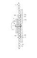
以下、本考案の実施形態について図面を参照して具体的に説明する。図1は本考案に係るループタイの全体正面、図2は該ループタイにおける装飾留め具による索体の挟着状態、図3は該挟着状態の縦断面、をそれぞれ示す。   Hereinafter, embodiments of the present invention will be specifically described with reference to the drawings. FIG. 1 is an overall front view of a loop tie according to the present invention, FIG. 2 is a state in which a cord body is clamped by a decorative fastener in the loop tie, and FIG. 3 is a longitudinal section in the clamped state.

この実施形態のループタイは、図1に示す用に、首掛け用のループL1を形成するボールチェーンからなる1本の索体1と、この索体1を並行状態で挿通する装飾留め具2とからなり、索体1の両端が留め金11によって連結されて下部側でもループL2を形成している。そして、装飾留め具2の楕円形厚板状の本体20の表面には、凹凸の装飾模様D(例えば、図示の斜線領域が金色の凸面部、無地領域が白銀色の凹面部をなす)が施されている。また、索体1のボールチェーンと装飾留め具2の本体20は、金、白金、銀、ホワイトゴールドの如き貴金属製か、銅等の一般金属に貴金属のメッキを施したものからなる。   The loop tie of this embodiment includes, as shown in FIG. 1, a single rope body 1 made of a ball chain that forms a loop L1 for necking, and a decorative fastener 2 that passes through the rope body 1 in a parallel state. Both ends of the cable body 1 are connected by a clasp 11 to form a loop L2 on the lower side. Then, on the surface of the oval thick plate-like main body 20 of the decorative fastener 2, there is an uneven decorative pattern D (for example, the shaded area shown in the figure forms a gold convex surface and the plain area forms a white silver concave surface). It has been subjected. The ball chain of the rope body 1 and the main body 20 of the decorative fastener 2 are made of a noble metal such as gold, platinum, silver, white gold, or a general metal such as copper plated with a noble metal.

図2(A)〜(C)で示すように、装飾留め具2の本体20の裏面側には、その楕円の長軸方向を使用時の上下方向として、上下部に挿通ガイド部6A,6Bが形成されると共に、中央部にネジ軸3が根元側の溶接によって垂直に立設されており、このネジ軸3に円板状のネジ板4が螺着されている。しかして、本体20の裏面側とネジ板4の内面側には、相互に対向して、ゴム又は合成樹脂からなる軟質ないし半硬質の円形の高分子層5A,5Bが形成されている。なお、ネジ軸3、ネジ板4、挿通ガイド部6A,6Bは、いずれも金属(貴金属を含む)製である。   As shown in FIGS. 2 (A) to 2 (C), on the back side of the main body 20 of the decorative fastener 2, the insertion guide portions 6 </ b> A and 6 </ b> B are formed on the upper and lower portions with the major axis direction of the ellipse as the vertical direction when used. Is formed, and a screw shaft 3 is erected vertically by welding at the base side, and a disk-shaped screw plate 4 is screwed to the screw shaft 3. Thus, soft or semi-rigid circular polymer layers 5A and 5B made of rubber or synthetic resin are formed on the back surface side of the main body 20 and the inner surface side of the screw plate 4 so as to face each other. The screw shaft 3, the screw plate 4, and the insertion guide portions 6A and 6B are all made of metal (including noble metal).

また、上下の挿通ガイド部6A,6Bは共に、金属帯板の両端側を円弧状に折り返して、左右一対の開環状の挿通部60,60を設けたもので、その中空平坦部で装飾留め具2の本体20の裏面側に溶接固着されている。   Both the upper and lower insertion guide portions 6A and 6B are provided with a pair of left and right open annular insertion portions 60 and 60 by folding both ends of the metal strip into an arc shape. It is welded and fixed to the back side of the main body 20 of the tool 2.

ループL1,L2を構成する索体1は、装飾留め具2の本体20の裏面側において、その2条が各々上下の挿通ガイド部6A,6Bの左右一方側の挿通部60を通して並行配置している。そして、この並行配置した2条の索体1,1の間にネジ軸3が突出すると共に、該ネジ軸3に螺合するネジ板4が並行配置した2条の索体1,1に被さる直径を有している。   The ropes 1 constituting the loops L1 and L2 are arranged in parallel on the back side of the main body 20 of the decorative fastener 2 through the insertion portions 60 on the left and right sides of the upper and lower insertion guide portions 6A and 6B. Yes. The screw shaft 3 projects between the two cords 1 and 1 arranged in parallel, and the screw plate 4 screwed to the screw shaft 3 covers the two cords 1 and 1 arranged in parallel. It has a diameter.

上記構成のループタイの使用に際しては、索体1のループL1を予め大きめに設定しておき、このループL1を使用者が頭から首部に通してワイシャツアの襟裏等に周回させ、この状態でネジ板4の螺合を緩め、索体1に対して装飾留め具2を上方へスライドさせながらループL1を縮め、該装飾留め具2の位置を決めた後、ネジ板4を捻回して締め付ければよい。これにより、装飾留め具2の本体20の裏面側で並行配置した2条の索体1,1は、図3に示すように、該本体20とネジ板4との間で挟み付けられ、そのボール部1a…が両側の高分子層5A,5Bに一部めり込む形で、当該本体20に対して移動不能に強く挟着固定される。   When using the loop tie having the above configuration, the loop L1 of the cord body 1 is set to be large in advance, and the user loops the loop L1 from the head to the neck and wraps around the shirt collar, etc. The screw plate 4 is loosened, the loop L1 is contracted while the decorative fastener 2 is slid upward with respect to the cord body 1, the position of the decorative fastener 2 is determined, and then the screw plate 4 is twisted and tightened Just do it. Thereby, the two cords 1, 1 arranged in parallel on the back side of the main body 20 of the decorative fastener 2 are sandwiched between the main body 20 and the screw plate 4, as shown in FIG. The ball portions 1a... Are firmly clamped and fixed to the main body 20 so as not to move in such a manner that the ball portions 1a.

従って、上記の挟着固定後のループタイでは、索体1及び装飾留め具2が金属製でかなりの重さになるが、索体1着用者の歩行や姿勢転換等で振動を受けたり、装飾留め具2や索体1の下側ループL2が手や衣服等に接触して多少引っ張られたりしても、装飾留め具2がずり下がって不体裁になることはなく、お洒落で良好な装着状態を維持できる。また、装飾留め具2のネジ板4を離脱方向に捻回すれば、装飾留め具2が索体1に対して移動自在になるから、該ループタイを取り外したり、首筋の締め付けを緩めたりする場合にも、非常に簡単な操作で済む。   Therefore, in the loop tie after the pinching and fixing, the cord body 1 and the decorative fastener 2 are made of metal and have a considerable weight. Even if the lower loop L2 of the fastener 2 or the cable body 1 comes into contact with a hand or clothes and is pulled slightly, the decorative fastener 2 does not slide down and becomes uncomfortable, and it is stylish and has a good wearing The state can be maintained. Further, if the screw plate 4 of the decorative fastener 2 is twisted in the direction of disengagement, the decorative fastener 2 becomes movable with respect to the cable body 1, so that the loop tie is removed or the tightening of the neck is loosened However, it is very easy.

一方、このようなループタイにあっては、索体1の挟着固定のために装飾留め具2の本体20裏面側にネジ軸3及び挿通ガイド部6A,6Bを設けるだけでよいから、索体1の固定用としての材料コスト及び加工コストの負担は僅かで済む。   On the other hand, in such a loop tie, it is only necessary to provide the screw shaft 3 and the insertion guide portions 6A and 6B on the back surface side of the main body 20 of the decorative fastener 2 in order to fix the cord body 1 so that the cord body 1 The burden of material cost and processing cost for fixing 1 is small.

なお、本考案のループタイにおける索体1は、上記の実施形態ではボール部1aと軸部1bとが交互に連結したボールチェーンを例示したが、小判鎖、喜平鎖、丸カン鎖、バーチェーン等の様々な金属製のものを好適に使用できると共に、糸で編んだ一般的な紐、革紐等の金属以外のものも使用可能である。ただし、本考案は、既述の優れた挟着固定作用から、特に硬く滑り易い金属製の索体を使用する場合に適用効果が大きい。また、索体1の両端は実施形態のように連結せずに分離した状態でもよいし、この分離した両端に適当な装飾部品を取り付けるようにしてもよい。   The rope 1 in the loop tie of the present invention is exemplified by a ball chain in which the ball portions 1a and the shaft portions 1b are alternately connected in the above embodiment, but an oval chain, a Kihei chain, a round can chain, a bar chain, etc. These can be suitably used, and other than metals such as general strings knitted with yarn and leather straps can also be used. However, the present invention has a large application effect especially when using a hard and slippery metal cable body because of the excellent clamping and fixing action described above. Further, the ends of the cable body 1 may be separated without being connected as in the embodiment, or appropriate decorative parts may be attached to the separated ends.

更に、本考案のループタイにおける装飾留め具2としては、実施形態で例示した楕円形のものに限らず、多種多様な形態及び材質のものを使用できる。また、実施形態では本体20とネジ板4の両方の対向面に高分子層6A,6Bを設けているが、その一方側のみに高分子層を設けてもよい。   Furthermore, the decorative fastener 2 in the loop tie of the present invention is not limited to the elliptical shape exemplified in the embodiment, and a variety of forms and materials can be used. In the embodiment, the polymer layers 6A and 6B are provided on the opposing surfaces of both the main body 20 and the screw plate 4, but the polymer layer may be provided only on one side thereof.

本考案の一実施形態に係るループタイの全体正面図である。1 is an overall front view of a loop tie according to an embodiment of the present invention. 同ループタイにおける装飾留め具による索体の挟着状態を示し、(A)は背面図、(B)は側面図、(C)は平面図である。The cord body is clamped by the decorative tie in the loop tie, (A) is a rear view, (B) is a side view, and (C) is a plan view. 同装飾留め具による索体の挟着状態を示す縦断側面図である。It is a vertical side view which shows the clamped state of the cable body by the same decorative fastener.

符号の説明Explanation of symbols

1 索体
2 装飾留め具
20 本体
3 ネジ軸
4 ネジ板
5A,5B 高分子層
6A,6B 挿通ガイド部
60 挿通部
D 装飾
L1 ループ
DESCRIPTION OF SYMBOLS 1 Cable body 2 Decoration fastener 20 Main body 3 Screw shaft 4 Screw board 5A, 5B Polymer layer 6A, 6B Insertion guide part 60 Insertion part D Decoration L1 Loop

Claims (4)

首掛け用のループを形成する索体と、この索体を挿通して前記ループを拡縮する装飾留め具とからなり、該装飾留め具の本体の裏面側にネジ軸が突設されると共に、該ネジ軸に螺合するネジ板を有し、このネジ板の締め付けによって当該ネジ板と本体との間で前記挿通した索体を挟着固定するように構成されてなるループタイ。   It comprises a cord forming a loop for hanging around the neck, and a decorative fastener that extends and contracts the loop through the cord, and a screw shaft projects from the back side of the main body of the decorative fastener, A loop tie having a screw plate that is screwed onto the screw shaft and configured to clamp and fix the inserted cable body between the screw plate and the main body by tightening the screw plate. 装飾留め具の本体とネジ板の互いの対向面の少なくとも一方側に、軟質ないし半硬質の高分子層が形成されてなる請求項1に記載のループタイ。   The loop tie according to claim 1, wherein a soft or semi-rigid polymer layer is formed on at least one side of the opposing surfaces of the decorative fastener body and the screw plate. 前記索体が金属製である請求項1又は2に記載のループタイ。   The loop tie according to claim 1 or 2, wherein the cable body is made of metal. 装飾留め具の本体の裏面側の上下部に2条の索体を並行して挿通させる挿通ガイド部が形成され、両挿通ガイド部の中間で且つ並行する2条の索体の間に前記ネジ軸が突出し、前記ネジ板が並行する2条の索体にかかる径を有する円板状をなす請求項1〜3のいずれかに記載のループタイ。   An insertion guide portion is formed in the upper and lower portions of the back surface side of the decorative fastener to allow the two cords to be inserted in parallel, and the screw is interposed between the two cords parallel to each other between the two insertion guide portions. The loop tie according to any one of claims 1 to 3, wherein the loop tie has a disk shape with a diameter protruding on two cords parallel to each other, the shaft protruding.
JP2008000828U 2008-02-18 2008-02-18 Loop tie Expired - Fee Related JP3141348U (en)

Priority Applications (1)

Application Number Priority Date Filing Date Title
JP2008000828U JP3141348U (en) 2008-02-18 2008-02-18 Loop tie

Applications Claiming Priority (1)

Application Number Priority Date Filing Date Title
JP2008000828U JP3141348U (en) 2008-02-18 2008-02-18 Loop tie

Publications (1)

Publication Number Publication Date
JP3141348U true JP3141348U (en) 2008-05-01

Family

ID=43291409

Family Applications (1)

Application Number Title Priority Date Filing Date
JP2008000828U Expired - Fee Related JP3141348U (en) 2008-02-18 2008-02-18 Loop tie

Country Status (1)

Country Link
JP (1) JP3141348U (en)

Similar Documents

Publication Publication Date Title
WO2017183545A1 (en) Mask provided with latch
JP2017193802A5 (en)
CN102469861A (en) Cord lock
US5440787A (en) Clasp for cloth neckwear and the like
JP3141348U (en) Loop tie
JP2009102772A (en) Cuff and method for producing the same
JP2006204511A (en) Pendant
JP3210422U (en) Head jewelry support
JP2010111971A (en) Necktie fastener, and detachable necktie equipped with the same
KR200471785Y1 (en) Fixing member for hairband
CN211379761U (en) Decorative structure for trousers with draw rope
JP2003247111A (en) Strap-adjusting tool
JP2002000312A (en) Fixing tool
US20180092436A1 (en) Fabric fastener
JP3157453U (en) Shoelace fastening device
US20090113604A1 (en) Attachment clip or support for a garment
JP3127432U (en) Accessories for fasteners
JP2007247125A (en) Necktie
CN206380803U (en) One moves position to fastens woven belt reed head without shelves difference
US494953A (en) Joseph s
JP3191883U (en) Sleeve folding holder
JPH0512249Y2 (en)
JP2013044068A (en) Decoration for jacket and jacket set
JP3128104U (en) Loop tie pendant
JP3196736U (en) Fastener for string connection

Legal Events

Date Code Title Description
R150 Certificate of patent (=grant) or registration of utility model

Free format text: JAPANESE INTERMEDIATE CODE: R150

FPAY Renewal fee payment (prs date is renewal date of database)

Free format text: PAYMENT UNTIL: 20110409

Year of fee payment: 3

LAPS Cancellation because of no payment of annual fees