JP2017193084A - Liquid ejection device and short circuit detection method - Google Patents
Liquid ejection device and short circuit detection method Download PDFInfo
- Publication number
- JP2017193084A JP2017193084A JP2016083676A JP2016083676A JP2017193084A JP 2017193084 A JP2017193084 A JP 2017193084A JP 2016083676 A JP2016083676 A JP 2016083676A JP 2016083676 A JP2016083676 A JP 2016083676A JP 2017193084 A JP2017193084 A JP 2017193084A
- Authority
- JP
- Japan
- Prior art keywords
- drive voltage
- ejection
- discharge
- liquid
- short circuit
- Prior art date
- Legal status (The legal status is an assumption and is not a legal conclusion. Google has not performed a legal analysis and makes no representation as to the accuracy of the status listed.)
- Granted
Links
Images


Classifications
-
- B—PERFORMING OPERATIONS; TRANSPORTING
- B41—PRINTING; LINING MACHINES; TYPEWRITERS; STAMPS
- B41J—TYPEWRITERS; SELECTIVE PRINTING MECHANISMS, i.e. MECHANISMS PRINTING OTHERWISE THAN FROM A FORME; CORRECTION OF TYPOGRAPHICAL ERRORS
- B41J2/00—Typewriters or selective printing mechanisms characterised by the printing or marking process for which they are designed
- B41J2/005—Typewriters or selective printing mechanisms characterised by the printing or marking process for which they are designed characterised by bringing liquid or particles selectively into contact with a printing material
- B41J2/01—Ink jet
- B41J2/015—Ink jet characterised by the jet generation process
- B41J2/04—Ink jet characterised by the jet generation process generating single droplets or particles on demand
- B41J2/045—Ink jet characterised by the jet generation process generating single droplets or particles on demand by pressure, e.g. electromechanical transducers
- B41J2/04501—Control methods or devices therefor, e.g. driver circuits, control circuits
- B41J2/04541—Specific driving circuit
-
- B—PERFORMING OPERATIONS; TRANSPORTING
- B41—PRINTING; LINING MACHINES; TYPEWRITERS; STAMPS
- B41J—TYPEWRITERS; SELECTIVE PRINTING MECHANISMS, i.e. MECHANISMS PRINTING OTHERWISE THAN FROM A FORME; CORRECTION OF TYPOGRAPHICAL ERRORS
- B41J2/00—Typewriters or selective printing mechanisms characterised by the printing or marking process for which they are designed
- B41J2/005—Typewriters or selective printing mechanisms characterised by the printing or marking process for which they are designed characterised by bringing liquid or particles selectively into contact with a printing material
- B41J2/01—Ink jet
- B41J2/015—Ink jet characterised by the jet generation process
- B41J2/04—Ink jet characterised by the jet generation process generating single droplets or particles on demand
- B41J2/045—Ink jet characterised by the jet generation process generating single droplets or particles on demand by pressure, e.g. electromechanical transducers
- B41J2/04501—Control methods or devices therefor, e.g. driver circuits, control circuits
- B41J2/0451—Control methods or devices therefor, e.g. driver circuits, control circuits for detecting failure, e.g. clogging, malfunctioning actuator
-
- B—PERFORMING OPERATIONS; TRANSPORTING
- B41—PRINTING; LINING MACHINES; TYPEWRITERS; STAMPS
- B41J—TYPEWRITERS; SELECTIVE PRINTING MECHANISMS, i.e. MECHANISMS PRINTING OTHERWISE THAN FROM A FORME; CORRECTION OF TYPOGRAPHICAL ERRORS
- B41J2/00—Typewriters or selective printing mechanisms characterised by the printing or marking process for which they are designed
- B41J2/005—Typewriters or selective printing mechanisms characterised by the printing or marking process for which they are designed characterised by bringing liquid or particles selectively into contact with a printing material
- B41J2/01—Ink jet
- B41J2/015—Ink jet characterised by the jet generation process
- B41J2/04—Ink jet characterised by the jet generation process generating single droplets or particles on demand
- B41J2/045—Ink jet characterised by the jet generation process generating single droplets or particles on demand by pressure, e.g. electromechanical transducers
- B41J2/04501—Control methods or devices therefor, e.g. driver circuits, control circuits
- B41J2/0458—Control methods or devices therefor, e.g. driver circuits, control circuits controlling heads based on heating elements forming bubbles
-
- B—PERFORMING OPERATIONS; TRANSPORTING
- B41—PRINTING; LINING MACHINES; TYPEWRITERS; STAMPS
- B41J—TYPEWRITERS; SELECTIVE PRINTING MECHANISMS, i.e. MECHANISMS PRINTING OTHERWISE THAN FROM A FORME; CORRECTION OF TYPOGRAPHICAL ERRORS
- B41J2/00—Typewriters or selective printing mechanisms characterised by the printing or marking process for which they are designed
- B41J2/005—Typewriters or selective printing mechanisms characterised by the printing or marking process for which they are designed characterised by bringing liquid or particles selectively into contact with a printing material
- B41J2/01—Ink jet
- B41J2/015—Ink jet characterised by the jet generation process
- B41J2/04—Ink jet characterised by the jet generation process generating single droplets or particles on demand
- B41J2/045—Ink jet characterised by the jet generation process generating single droplets or particles on demand by pressure, e.g. electromechanical transducers
- B41J2/04501—Control methods or devices therefor, e.g. driver circuits, control circuits
- B41J2/04581—Control methods or devices therefor, e.g. driver circuits, control circuits controlling heads based on piezoelectric elements
-
- B—PERFORMING OPERATIONS; TRANSPORTING
- B41—PRINTING; LINING MACHINES; TYPEWRITERS; STAMPS
- B41J—TYPEWRITERS; SELECTIVE PRINTING MECHANISMS, i.e. MECHANISMS PRINTING OTHERWISE THAN FROM A FORME; CORRECTION OF TYPOGRAPHICAL ERRORS
- B41J2/00—Typewriters or selective printing mechanisms characterised by the printing or marking process for which they are designed
- B41J2/005—Typewriters or selective printing mechanisms characterised by the printing or marking process for which they are designed characterised by bringing liquid or particles selectively into contact with a printing material
- B41J2/01—Ink jet
- B41J2/015—Ink jet characterised by the jet generation process
- B41J2/04—Ink jet characterised by the jet generation process generating single droplets or particles on demand
- B41J2/045—Ink jet characterised by the jet generation process generating single droplets or particles on demand by pressure, e.g. electromechanical transducers
- B41J2/04501—Control methods or devices therefor, e.g. driver circuits, control circuits
- B41J2/04586—Control methods or devices therefor, e.g. driver circuits, control circuits controlling heads of a type not covered by groups B41J2/04575 - B41J2/04585, or of an undefined type
-
- B—PERFORMING OPERATIONS; TRANSPORTING
- B41—PRINTING; LINING MACHINES; TYPEWRITERS; STAMPS
- B41J—TYPEWRITERS; SELECTIVE PRINTING MECHANISMS, i.e. MECHANISMS PRINTING OTHERWISE THAN FROM A FORME; CORRECTION OF TYPOGRAPHICAL ERRORS
- B41J2/00—Typewriters or selective printing mechanisms characterised by the printing or marking process for which they are designed
- B41J2/005—Typewriters or selective printing mechanisms characterised by the printing or marking process for which they are designed characterised by bringing liquid or particles selectively into contact with a printing material
- B41J2/01—Ink jet
- B41J2/015—Ink jet characterised by the jet generation process
- B41J2/04—Ink jet characterised by the jet generation process generating single droplets or particles on demand
- B41J2/045—Ink jet characterised by the jet generation process generating single droplets or particles on demand by pressure, e.g. electromechanical transducers
- B41J2/04501—Control methods or devices therefor, e.g. driver circuits, control circuits
- B41J2/04588—Control methods or devices therefor, e.g. driver circuits, control circuits using a specific waveform
Landscapes
- Ink Jet (AREA)
- Particle Formation And Scattering Control In Inkjet Printers (AREA)
Abstract
Description
本発明は液体吐出装置、及び短絡検出方法に係り、特に液体吐出ヘッドにおける短絡検出技術に関する。 The present invention relates to a liquid ejection device and a short circuit detection method, and more particularly to a short circuit detection technique in a liquid ejection head.
特許文献1は、複数の吐出素子が備えられた液体吐出ヘッドが搭載される液体吐出装置が記載されている。特許文献1に記載の液体吐出装置は、液体吐出ヘッドに具備される吐出素子間の短絡を検出している。 Japanese Patent Application Laid-Open No. 2004-228561 describes a liquid discharge apparatus on which a liquid discharge head provided with a plurality of discharge elements is mounted. The liquid ejection device described in Patent Document 1 detects a short circuit between ejection elements included in a liquid ejection head.
吐出素子間の短絡の検出には、キャパシタンス測定、又は漏洩電流測定などの電気的測定、若しくは光学顕微鏡が用いられる配線の観察、又は電気的刺激を与えている間の赤外線画像の観察などの配線の観察が適用される。 For detection of short circuit between discharge elements, electrical measurement such as capacitance measurement or leakage current measurement, wiring observation using optical microscope, or wiring such as observation of infrared image while applying electrical stimulus The observations apply.
なお、本明細書における吐出素子の用語は、特許文献1における流体吐出部の用語に相当する。本明細書における液体吐出ヘッドの用語は、特許文献1におけるプリントヘッドの用語に相当する。本明細書における液体吐出装置の用語は、特許文献1における流体吐出装置の用語に相当する。 The term “ejection element” in the present specification corresponds to the term “fluid ejection unit” in Patent Document 1. The term “liquid ejection head” in the present specification corresponds to the term “print head” in Patent Document 1. The term “liquid ejection device” in this specification corresponds to the term “fluid ejection device” in Patent Document 1.
特許文献2は、吐出素子の駆動電極部と電気接続される検出電極部を備えた液体吐出ヘッドが記載されている。特許文献2に記載の液体吐出ヘッドは、検出モードにおいて、駆動電極部に検出用駆動電圧が印加される。検出電極部に検出電圧が現れると、検出電極部から電圧検出回路に検出信号が入力される。
電圧検出回路が用いられて、検出電極部に現れた電圧から、液体吐出ヘッドの各種部品の電気接続状態が検出される。なお、本明細書における吐出素子の用語は、特許文献2における圧電部の用語に相当する。
A voltage detection circuit is used to detect the electrical connection state of various components of the liquid ejection head from the voltage appearing at the detection electrode portion. The term “ejection element” in this specification corresponds to the term “piezoelectric part” in
また、本明細書における液体吐出ヘッドの用語は、特許文献2におけるインクジェットヘッドの用語に相当する。本明細書における検出の用語は、特許文献2における検査の用語に相当する。
Further, the term “liquid ejection head” in this specification corresponds to the term “inkjet head” in
特許文献3は、吐出駆動用の主波形部と、主波形部との組み合わせにより吐出を抑制する副波形部とを組み合わせて、回路制御素子の故障など制御不良が発生した場合でも常時吐出が防止される液体吐出装置が記載されている。 Patent Document 3 discloses a combination of a main waveform section for ejection driving and a sub-waveform section that suppresses ejection by combining the main waveform section to prevent constant ejection even when a control failure such as a failure of a circuit control element occurs. A liquid ejection device is described.
液体吐出ヘッドが液体吐出装置へ搭載された後に、吐出素子と電気接続される電気配線間に短絡が発生した場合、いずれの吐出素子と電気接続される電気配線にショートが発生しているかの判断が可能であれば、液体吐出ヘッドの交換の要否の判断が可能である。 If a short circuit occurs between the electrical wirings that are electrically connected to the ejection elements after the liquid ejection head is mounted on the liquid ejection device, a determination is made as to which ejection element is electrically connected to the electrical wiring. If it is possible, it is possible to determine whether or not the liquid discharge head needs to be replaced.
また、該当する吐出素子を非使用化させることで、液体吐出ヘッドが交換されることなく、継続した使用が可能である。 Further, by disabling the corresponding ejection element, the liquid ejection head can be continuously used without being replaced.
特許文献1、及び特許文献2には、液体吐出ヘッドの吐出の有無により吐出素子の短絡の有無を検出することに関する記載、又は示唆はない。また、特許文献3に記載の構成では、吐出素子間の短絡を検出することは困難である。
Patent Document 1 and
本発明はこのような事情に鑑みてなされたもので、液体吐出ヘッドの吐出有無を用いて吐出素子間の短絡検出が可能とされる液体吐出装置、及び短絡検出方法を提供することを目的とする。 The present invention has been made in view of such circumstances, and an object of the present invention is to provide a liquid ejection apparatus and a short-circuit detection method capable of detecting a short circuit between ejection elements using the presence or absence of ejection of a liquid ejection head. To do.
上記目的を達成するために、次の発明態様を提供する。 In order to achieve the above object, the following invention aspects are provided.
第1態様の液体吐出装置は、複数の吐出素子を備えた液体吐出ヘッドと、複数の吐出素子の短絡検出の際に使用される第一駆動電圧、及び複数の吐出素子の短絡検出の際に使用される第二駆動電圧を生成する駆動電圧生成部と、吐出素子間の短絡検出対象の第一吐出素子に対して第一駆動電圧を供給し、第一吐出素子との短絡が疑われる第二吐出素子に対して第二駆動電圧を供給する駆動電圧供給部と、を備え、駆動電圧生成部は、第一吐出素子に対して第一駆動電圧が単独で印加された場合の第一吐出素子からの液体の吐出の有無と、第一吐出素子に対して第一駆動電圧、及び第二駆動電圧が印加された場合の第一吐出素子からの液体の吐出の有無とが異なる第一駆動電圧、及び第二駆動電圧を生成する液体吐出装置である。 The liquid ejection apparatus according to the first aspect includes a liquid ejection head including a plurality of ejection elements, a first drive voltage used when detecting a short circuit of the plurality of ejection elements, and a short circuit detection of the plurality of ejection elements. A first drive voltage is supplied to a drive voltage generation unit that generates a second drive voltage to be used and a first discharge element that is a short-circuit detection target between discharge elements, and a short circuit with the first discharge element is suspected. A driving voltage supply unit that supplies a second driving voltage to the two ejection elements, and the driving voltage generation unit is configured to perform the first ejection when the first driving voltage is independently applied to the first ejection element. The first drive in which the presence / absence of liquid discharge from the element is different from the presence / absence of liquid discharge from the first discharge element when the first drive voltage and the second drive voltage are applied to the first discharge element The liquid ejection device generates a voltage and a second drive voltage.
第1態様によれば、短絡検出対象の第一吐出素子と、第一吐出素子との短絡が疑われる第二吐出素子とが短絡している場合と、第一吐出素子と第二吐出素子とが短絡していない場合とは、少なくとも第一吐出素子からの吐出の有無が異なるので、第一吐出素子からの吐出の有無に応じた第一吐出素子と第二吐出素子との短絡検出が可能である。 According to the first aspect, when the first discharge element subject to short circuit detection and the second discharge element suspected of being short-circuited with the first discharge element are short-circuited, the first discharge element and the second discharge element Since there is at least the presence or absence of discharge from the first discharge element, the short-circuit between the first discharge element and the second discharge element can be detected according to the presence or absence of discharge from the first discharge element. It is.
吐出素子とは、液体を吐出させる最小単位である。吐出素子の構成例として、液体を吐出させるノズル部、及びノズル部の液体を加圧する加圧素子を備える構成が挙げられる。 An ejection element is a minimum unit for ejecting liquid. Examples of the configuration of the ejection element include a configuration including a nozzle unit that ejects liquid and a pressurizing element that pressurizes the liquid in the nozzle unit.
また、ノズル部の構成例として、ノズル開口、圧力室、及び圧力室と連通される供給口を備える構成が挙げられる。 Further, as a configuration example of the nozzle portion, a configuration including a nozzle opening, a pressure chamber, and a supply port communicating with the pressure chamber can be given.
吐出素子間の短絡には、各吐出素子と電気接続される電気配線、電極、及び駆動電圧の出力端子の少なくともいずれかの短絡が含まれる。 The short circuit between the discharge elements includes a short circuit of at least one of the electrical wiring, the electrode, and the output terminal of the drive voltage that are electrically connected to each discharge element.
第一吐出素子と短絡が疑われる第二吐出素子の例として、第一吐出素子と隣接する位置に配置される吐出素子が挙げられる。第一吐出素子と隣接する位置は、第一方向の隣接位置でもよいし、第一方向と直交する第二方向の隣接位置でもよい。第一吐出素子と隣接する位置は、第一方向、又は第二方向と斜めに交差する第三方向の隣接位置でもよい。 As an example of the second discharge element suspected of being short-circuited with the first discharge element, there is a discharge element disposed at a position adjacent to the first discharge element. The position adjacent to the first ejection element may be an adjacent position in the first direction or an adjacent position in the second direction perpendicular to the first direction. The position adjacent to the first ejection element may be an adjacent position in the first direction or a third direction that obliquely intersects the second direction.
駆動電圧の供給とは駆動電圧供給部の動作を表している。駆動電圧の印加とは吐出素子から見た駆動電圧の供給の結果を表している。各吐出素子と電気接続される電気配線に短絡、又は開放等の電気的異常は発生している場合は、駆動電圧供給部から供給されていない駆動電圧が印加されること、又は駆動電圧供給部から供給されるべき駆動電圧が印加されないことがあり得る。 The supply of drive voltage represents the operation of the drive voltage supply unit. The application of the drive voltage represents the result of supplying the drive voltage as viewed from the ejection element. When an electrical abnormality such as a short circuit or an open circuit has occurred in the electrical wiring electrically connected to each ejection element, a drive voltage not supplied from the drive voltage supply unit is applied, or the drive voltage supply unit It is possible that the drive voltage to be supplied from is not applied.
第一吐出素子に対する第一駆動電圧の供給の後に、第二吐出素子に対する第二駆動電圧の供給がされてもよい。第二吐出素子に対する第二駆動電圧の供給の後に、第一吐出素子に対する第一駆動電圧の供給がされてもよい。 The second drive voltage may be supplied to the second discharge element after the first drive voltage is supplied to the first discharge element. The first drive voltage may be supplied to the first discharge element after the second drive voltage is supplied to the second discharge element.
第一駆動電圧の第一駆動波形、及び第二駆動電圧の第二駆動波形を取得する駆動波形取得部を備え、駆動電圧生成部は、取得された第一駆動波形に基づく第一駆動電圧、及び第二駆動波形に基づく第二駆動電圧を生成することが可能である。 A drive waveform acquisition unit that acquires a first drive waveform of the first drive voltage and a second drive waveform of the second drive voltage, and the drive voltage generation unit includes a first drive voltage based on the acquired first drive waveform, And a second drive voltage based on the second drive waveform can be generated.
第一駆動波形、及び第二駆動波形が記憶される波形記憶部を備え、駆動波形取得部は、波形記憶部から第一駆動波形、及び第二駆動波形を読み出すことで、第一駆動波形、及び第二駆動波形を取得してもよい。 A waveform storage unit for storing the first drive waveform and the second drive waveform is provided, and the drive waveform acquisition unit reads the first drive waveform and the second drive waveform from the waveform storage unit, whereby the first drive waveform, The second drive waveform may be acquired.
第2態様は、第1態様の液体吐出装置において、第一吐出素子と電気接続される第一電気配線と、第二吐出素子と電気接続される第二電気配線とは隣り合う位置に配置される構成としてもよい。 According to a second aspect, in the liquid ejection device according to the first aspect, the first electrical wiring electrically connected to the first ejection element and the second electrical wiring electrically coupled to the second ejection element are arranged at adjacent positions. It is good also as a structure to be.
第2態様によれば、第一吐出素子と電気接続される第一電気配線と、第二吐出素子と電気接続される第二電気配線との短絡が発生しやすい場合について、第一吐出素子と第二吐出素子との短絡検出が可能である。 According to the second aspect, in the case where a short circuit between the first electrical wiring electrically connected to the first ejection element and the second electrical wiring electrically coupled to the second ejection element is likely to occur, Short-circuit detection with the second ejection element is possible.
第一電気配線、及び第二電気配線は、液体吐出ヘッドの内部の電気配線でもよいし、液体吐出ヘッドと電気接続される配線部材に形成された電気配線、及び配線部材と電気接続される電気回路基板に形成された電気配線の少なくともいずれかでもよい。 The first electrical wiring and the second electrical wiring may be electrical wiring inside the liquid ejection head, electrical wiring formed on a wiring member that is electrically connected to the liquid ejection head, and electrical that is electrically connected to the wiring member. It may be at least one of the electrical wirings formed on the circuit board.
第3態様は、第1態様又は第2態様の液体吐出装置において、第一吐出素子に供給される第一駆動電圧が出力される第一駆動電圧出力端子と、第二吐出素子に供給される第二駆動電圧が出力される第二駆動電圧出力端子とは、隣り合う位置に配置される構成としてもよい。 According to a third aspect, in the liquid ejection device according to the first aspect or the second aspect, the first drive voltage output terminal that outputs the first drive voltage supplied to the first ejection element and the second ejection element are supplied. The second drive voltage output terminal from which the second drive voltage is output may be arranged at an adjacent position.
第3態様によれば、第一吐出素子に供給される第一駆動電圧が出力される第一駆動電圧出力端子と、第二吐出素子に供給される第二駆動電圧が出力される第二駆動電圧出力端子との短絡が発生しやすい場合について、第一吐出素子と第二吐出素子との短絡検出が可能である。 According to the third aspect, the first drive voltage output terminal from which the first drive voltage supplied to the first discharge element is output, and the second drive from which the second drive voltage supplied to the second discharge element is output. When a short circuit with the voltage output terminal is likely to occur, it is possible to detect a short circuit between the first discharge element and the second discharge element.
第4態様は、第1態様から第3態様のいずれか一態様の液体吐出装置において、駆動電圧供給部は、第一吐出素子と短絡の可能性がある全ての吐出素子を第二吐出素子として、第二駆動電圧を供給する構成としてもよい。 According to a fourth aspect, in the liquid ejection device according to any one of the first to third aspects, the drive voltage supply unit uses all ejection elements that may be short-circuited with the first ejection element as the second ejection elements. The second drive voltage may be supplied.
第4態様によれば、第一吐出素子と短絡の可能性がある全ての吐出素子について、第一吐出素子との短絡検出が可能である。 According to the fourth aspect, it is possible to detect a short circuit with the first discharge element for all the discharge elements that may be short-circuited with the first discharge element.
第二吐出素子が複数存在する場合は、複数の第二吐出素子のそれぞれについて、順に第一吐出素子との短絡検出を実行してもよい。第二吐出素子が複数存在する場合は、複数の第二吐出素子の一部、又は全部をまとめて、第一吐出素子との短絡検出を実行してもよい。 When there are a plurality of second ejection elements, short-circuit detection with the first ejection elements may be sequentially performed for each of the plurality of second ejection elements. When there are a plurality of second ejection elements, a part or all of the plurality of second ejection elements may be collected to detect a short circuit with the first ejection element.
第5態様は、第1態様から第4態様のいずれか一態様の液体吐出装置において、駆動電圧供給部から第一吐出素子へ第一駆動電圧が供給される期間、及び駆動電圧供給部から第二吐出素子へ第二駆動電圧が供給される期間において、複数の吐出素子から吐出される液体が通過する液体通過領域を撮像する撮像装置を用いて得られた撮像データを取得する撮像データ取得部を備えた構成としてもよい。 According to a fifth aspect, in the liquid ejection device according to any one of the first aspect to the fourth aspect, the period during which the first drive voltage is supplied from the drive voltage supply unit to the first ejection element, and the first from the drive voltage supply unit An imaging data acquisition unit that acquires imaging data obtained using an imaging device that images a liquid passage region through which liquid ejected from a plurality of ejection elements passes during a period in which the second drive voltage is supplied to the two ejection elements It is good also as a structure provided with.
第5態様によれば、撮像装置を用いて得られた撮像データに基づき、第一吐出素子からの吐出の有無が判断可能である。 According to the fifth aspect, it is possible to determine the presence / absence of ejection from the first ejection element based on imaging data obtained using the imaging device.
第6態様は、第1態様から第4態様のいずれか一態様の液体吐出装置において、駆動電圧供給部から第一吐出素子へ第一駆動電圧が供給された期間の後であり、駆動電圧供給部から第二吐出素子へ第二駆動電圧が供給された期間の後に、媒体におけるドットの有無を観察した観察結果を取得する観察結果情報取得部を備えた構成としてもよい。 A sixth aspect is the liquid discharge apparatus according to any one of the first aspect to the fourth aspect, after the period during which the first drive voltage is supplied from the drive voltage supply unit to the first discharge element, and the drive voltage supply It is good also as a structure provided with the observation result information acquisition part which acquires the observation result which observed the presence or absence of the dot in a medium after the period when the 2nd drive voltage was supplied to the 2nd discharge element from the part.
第6態様によれば、媒体の観察結果を表す観察データに基づき、第一吐出素子からの吐出の有無が判断可能である。 According to the sixth aspect, it is possible to determine the presence / absence of ejection from the first ejection element based on the observation data representing the observation result of the medium.
第7態様は、第1態様から第6態様のいずれか一態様の液体吐出装置において、駆動電圧生成部は、第一吐出素子に対して単独で印加された場合に、第一吐出素子から液体を吐出させない第一駆動電圧、及び第二吐出素子に対して単独で印加された場合に、第二吐出素子から液体を吐出させない第二駆動電圧を生成し、第一駆動電圧、及び第二駆動電圧は、第一吐出素子、及び第二吐出素子に対して第一駆動電圧、及び第二駆動電圧が印加された場合に、第一吐出素子、及び第二吐出素子から液体を吐出させる駆動電圧である構成としてもよい。 According to a seventh aspect, in the liquid ejection device according to any one of the first aspect to the sixth aspect, when the drive voltage generation unit is applied alone to the first ejection element, the liquid is discharged from the first ejection element. The first drive voltage that does not discharge the liquid and the second drive voltage that does not discharge the liquid from the second discharge element when applied alone to the second discharge element, the first drive voltage and the second drive The voltage is a drive voltage for discharging liquid from the first discharge element and the second discharge element when the first drive voltage and the second drive voltage are applied to the first discharge element and the second discharge element. It is good also as composition which is.
第7態様によれば、第一吐出素子に対する第一駆動電圧の供給、及び第二吐出素子に対する第二駆動電圧の供給がされた場合に第一吐出素子、及び第二吐出素子から液体が吐出されると、第一吐出素子と第二吐出素子との短絡が発生していると判断可能である。 According to the seventh aspect, liquid is discharged from the first discharge element and the second discharge element when the first drive voltage is supplied to the first discharge element and the second drive voltage is supplied to the second discharge element. Then, it can be determined that a short circuit has occurred between the first ejection element and the second ejection element.
第7態様において、第一吐出素子に対する第一駆動電圧の供給の後に、第二吐出素子に対する第二駆動電圧の供給がされてもよい。第二吐出素子に対する第二駆動電圧の供給の後に、第一吐出素子に対する第一駆動電圧の供給がされてもよい。 In the seventh aspect, the second drive voltage may be supplied to the second discharge element after the first drive voltage is supplied to the first discharge element. The first drive voltage may be supplied to the first discharge element after the second drive voltage is supplied to the second discharge element.
第8態様は、第7態様の液体吐出装置において、駆動電圧供給部は、第一駆動電圧を第一吐出素子へ供給した後に、第一駆動電圧の始期から第二駆動電圧の始期までの期間が吐出素子の共振周期を含む予め決められた範囲の範囲内となる第二駆動電圧を第二吐出素子へ供給する構成としてもよい。 According to an eighth aspect, in the liquid ejection device according to the seventh aspect, the drive voltage supply unit supplies the first drive voltage to the first ejection element and then the period from the start of the first drive voltage to the start of the second drive voltage. May be configured to supply the second ejection voltage to the second ejection element within a predetermined range including the resonance period of the ejection element.
第8態様によれば、第一駆動電圧の始期から第二駆動電圧の始期までの期間が吐出素子の共振周期を含む予め決められた範囲の範囲内とされることで、第一吐出素子と第二吐出素子とが短絡している場合に第一吐出素子、及び第二吐出素子へ第一駆動電圧、及び第二駆動電圧が印加された際に、第一吐出素子、及び第二吐出素子から液体が吐出し易くなる。 According to the eighth aspect, the period from the start of the first drive voltage to the start of the second drive voltage is within a predetermined range including the resonance period of the discharge element, whereby the first discharge element and When the first drive voltage and the second drive voltage are applied to the first discharge element and the second discharge element when the second discharge element is short-circuited, the first discharge element and the second discharge element From this, it becomes easy to discharge the liquid.
共振周期を含む予め決められた範囲は、上限値、及び下限値を共振周期に定数を乗算して算出することができる。定数は第一吐出素子から液体を吐出させることが可能であるという条件から決められる。 The predetermined range including the resonance period can be calculated by multiplying the resonance period by a constant with the upper limit value and the lower limit value. The constant is determined from the condition that the liquid can be discharged from the first discharge element.
第9態様は、第1態様から第6態様のいずれか一態様の液体吐出装置において、駆動電圧生成部は、第一吐出素子に対して単独で印加された場合に、第一吐出素子から液体を吐出させない第一駆動電圧、及び第二吐出素子に対して単独で印加された場合に、第二吐出素子から液体を吐出させない第二駆動電圧を生成し、第一駆動電圧、及び第二駆動電圧は、第一吐出素子に対して第一駆動電圧、及び第二駆動電圧が印加された場合に、第一吐出素子から液体を吐出させる駆動電圧であり、第二吐出素子に対して第一駆動電圧、及び第二駆動電圧が印加された場合に、第二吐出素子から液体を吐出させない駆動電圧である構成としてもよい。 According to a ninth aspect, in the liquid ejection device according to any one of the first aspect to the sixth aspect, when the drive voltage generation unit is applied alone to the first ejection element, the liquid is discharged from the first ejection element. The first drive voltage that does not discharge the liquid and the second drive voltage that does not discharge the liquid from the second discharge element when applied alone to the second discharge element, the first drive voltage and the second drive The voltage is a drive voltage for discharging liquid from the first discharge element when the first drive voltage and the second drive voltage are applied to the first discharge element. A configuration may be employed in which the liquid is not ejected from the second ejection element when the driving voltage and the second driving voltage are applied.
第9態様によれば、第一吐出素子に対する第一駆動電圧の供給、及び第二吐出素子に対する第二駆動電圧の供給された場合に第一吐出素子から液体が吐出されると、第一吐出素子と第二吐出素子との短絡が発生していると判断可能である。 According to the ninth aspect, when the liquid is discharged from the first discharge element when the first drive voltage is supplied to the first discharge element and the second drive voltage is supplied to the second discharge element, the first discharge voltage is discharged. It can be determined that a short circuit has occurred between the element and the second ejection element.
第10態様は、第9態様の液体吐出装置において、駆動電圧供給部は、第二駆動電圧を第二吐出素子へ供給した後に、第二駆動電圧の始期から第一駆動電圧の始期までの期間が吐出素子の共振周期を含む予め決められた範囲の範囲内となる第一駆動電圧を第一吐出素子へ供給する構成としてもよい。 According to a tenth aspect, in the liquid ejection device according to the ninth aspect, the drive voltage supply unit supplies the second drive voltage to the second ejection element and then the period from the start of the second drive voltage to the start of the first drive voltage. May be configured to supply a first drive voltage that falls within a predetermined range including the resonance period of the ejection element to the first ejection element.
第10態様によれば、第二駆動電圧の始期から第一駆動電圧の始期までの期間が吐出素子の共振周期の二分の一を含む予め決められた範囲の範囲内とされることで、第一吐出素子と第二吐出素子とが短絡している場合に第一吐出素子へ第一駆動電圧、及び第二駆動電圧が印加されると第一吐出素子から液体が吐出しにくくなる。 According to the tenth aspect, the period from the start of the second drive voltage to the start of the first drive voltage is set within a predetermined range including one half of the resonance period of the ejection element. When the first ejection element and the second ejection element are short-circuited, if the first drive voltage and the second drive voltage are applied to the first ejection element, it becomes difficult to eject liquid from the first ejection element.
第11態様の短絡検出方法は、複数の吐出素子を備えた液体吐出ヘッドにおける吐出素子間の短絡を検出する短絡検出方法であって、複数の吐出素子の短絡検出の際に使用される第一駆動電圧、及び複数の吐出素子の短絡検出の際に使用される第二駆動電圧を生成する駆動電圧生成工程と、吐出素子間の短絡検出対象の第一吐出素子に対して第一駆動電圧を供給し、第一吐出素子との短絡が疑われる第二吐出素子に対して第二駆動電圧を供給する駆動電圧供給工程と、第一吐出素子の吐出の有無に基づき、第一吐出素子と第二吐出素子との短絡の有無を検出する検出工程と、を含み、駆動電圧生成工程は、第一吐出素子に対して第一駆動電圧が単独で印加された場合の第一吐出素子からの液体の吐出の有無と、第一吐出素子に対して第一駆動電圧、及び第二駆動電圧が印加された場合の第一吐出素子からの液体の吐出の有無とが異なる第一駆動電圧、及び第二駆動電圧を生成する短絡検出方法である。 A short circuit detection method according to an eleventh aspect is a short circuit detection method for detecting a short circuit between ejection elements in a liquid ejection head having a plurality of ejection elements, and is a first method used for detecting a short circuit between a plurality of ejection elements. A driving voltage generating step for generating a driving voltage and a second driving voltage used in detecting a short circuit of the plurality of ejection elements; and a first driving voltage for the first ejection element to be detected for a short circuit between the ejection elements. A supply voltage supply step for supplying a second drive voltage to the second discharge element that is suspected of being short-circuited with the first discharge element, and whether or not the first discharge element is discharged. A detection step for detecting the presence or absence of a short circuit with the two discharge elements, and the drive voltage generation step includes a liquid from the first discharge element when the first drive voltage is applied alone to the first discharge element. The first drive for the first ejection element Pressure, and the presence of the ejection of the liquid from the first discharge element is a short circuit detecting method for generating different first driving voltage, and the second driving voltage when the second driving voltage is applied.
第11態様によれば、第1態様と同様の効果を得ることができる。 According to the eleventh aspect, the same effect as in the first aspect can be obtained.
第11態様において、第2態様から第10態様で特定した事項と同様の事項を適宜組み合わせることができる。その場合、液体吐出装置において特定される処理や機能を担う構成要素は、これに対応する処理や機能を担う短絡検出方法の構成要素として把握することができる。 In the eleventh aspect, matters similar to the matters specified in the second aspect to the tenth aspect can be appropriately combined. In that case, the component responsible for the process or function specified in the liquid ejection apparatus can be grasped as the component of the short-circuit detection method responsible for the process or function corresponding thereto.
本発明によれば、短絡検出対象の第一吐出素子と、第一吐出素子との短絡が疑われる第二吐出素子とが短絡している場合と、第一吐出素子と第二吐出素子とが短絡していない場合とは、少なくとも第一吐出素子からの吐出の有無が異なるので、第一吐出素子からの吐出の有無に応じた第一吐出素子と第二吐出素子との短絡検出が可能である。 According to the present invention, when the first discharge element subject to short circuit detection and the second discharge element suspected of short-circuiting with the first discharge element are short-circuited, the first discharge element and the second discharge element are Since there is at least whether or not discharge from the first discharge element is different from the case where there is no short circuit, it is possible to detect short circuit between the first discharge element and the second discharge element according to the presence or absence of discharge from the first discharge element. is there.
以下、添付図面に従って本発明の好ましい実施の形態について詳説する。本明細書では、既に説明された構成には同一の符号を付して、説明が適宜省略されることとする。 Hereinafter, preferred embodiments of the present invention will be described in detail with reference to the accompanying drawings. In the present specification, the components already described are denoted by the same reference numerals, and description thereof will be omitted as appropriate.
[液体吐出装置の説明]
<全体構成>
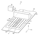
図1は液体吐出装置の全体構成図である。図1に示されたインクジェット記録装置10は、複数の吐出素子が備えられたインクジェットヘッド12が備えられている。インクジェットヘッド12はチューブ14を介してインクタンク16からインクが供給される。なお、図1では吐出素子の図示は省略される。
[Description of Liquid Discharge Device]
<Overall configuration>
FIG. 1 is an overall configuration diagram of the liquid ejection apparatus. An ink
吐出素子は図4において符号68が付されて図示される。以下、吐出素子は、図4に示される吐出素子68を表している。インクジェットヘッド12は液体吐出ヘッドの一態様である。インクは液体の一態様である。
The discharge element is shown in FIG. Hereinafter, the ejection element represents the
図1に示されたインクジェット記録装置10は、用紙18を搬送する用紙搬送部20が備えられている。図1に示される用紙搬送部20は、用紙18の裏側面を支持する搬送ベルト22が備えられている。
The ink
搬送ベルト22は、無端状であり、二つのローラに巻き掛けられている。搬送ベルト22は、用紙18を支持する用紙支持領域に複数の吸着穴が設けられている。搬送ベルト22が巻き掛けられる二つのローラ、及び複数の吸着穴の図示は省略される。
The
図1では、符号Xが用いられて用紙幅方向が表されている。また、符号Yが用いられて用紙搬送方向が表されている。更に、符号Zが用いられて上方向が表されている。用紙幅方向は用紙搬送方向と直交する方向である。 In FIG. 1, the sheet width direction is expressed by using the symbol X. Further, the symbol Y is used to indicate the sheet conveyance direction. Furthermore, the upper direction is represented using the symbol Z. The paper width direction is a direction orthogonal to the paper transport direction.
用紙搬送方向は用紙搬送部20が用いられて用紙18が搬送される方向である。上方向は重力方向と反対方向である。用紙幅方向、及び用紙搬送方向が水平方向と平行な方向の場合、上方向は用紙幅方向、及び用紙搬送方向の両者と直交する。
The paper transport direction is a direction in which the
本明細書における直交、又は垂直の用語は、90度を超える角度で交差する場合、又は90度未満の角度で交差する場合のうち、90度で交差する場合と同一の作用効果を奏する実質的な直交、又は垂直が含まれる。 In the present specification, the terms orthogonal or vertical are substantially the same as the case of crossing at 90 degrees out of the case of crossing at an angle of more than 90 degrees or of less than 90 degrees. Orthogonal or vertical.
また、本明細書における平行の用語は、二方向が非平行であるものの、平行と同一の作用効果を奏する実質的な平行が含まれる。更に、本明細書における同一の用語は、相違があるものの、同一と同様の作用効果を得ることができる実質的な同一が含まれる。 In addition, the term “parallel” in this specification includes substantial parallelism having the same effect as parallel, although the two directions are not parallel. Furthermore, the same term in this specification includes the substantially same thing which can obtain the effect similar to the same though there is a difference.
図1に示されたインクジェットヘッド12は、用紙幅方向について、用紙18の全長以上の長さに渡って複数の吐出素子が配置されたライン型液体吐出ヘッドである。
The
インクジェットヘッド12は、ヘッド支持部材が用いられて、用紙幅方向の両端が支持されている。ヘッド支持部材の図示は省略される。インクジェットヘッド12を上下方向に移動させるヘッド昇降機構と兼用されてもよい。
The
図1に示された用紙18は、インクジェットヘッド12から吐出させたインクが用いられたドット24が形成されている。
The
本実施形態では、インクジェットヘッド12と用紙18とを相対的に搬送させる相対搬送部の例として、固定配置されたインクジェットヘッド12に対して用紙18を搬送させる用紙搬送部20が適用される態様が例示されている。図1に示された符号が付与されていない矢印線は用紙18の搬送方向である搬送ベルト22の走行方向を表している。
In the present embodiment, as an example of a relative conveyance unit that relatively conveys the
インクジェットヘッド12と用紙18とを相対的に搬送させる相対搬送部は、固定配置された用紙18に対してインクジェットヘッド12を移動させるヘッド移動部であり、図示されないがヘッド移動部に適用されてもよい。また、図示されないヘッド移動部が用いられてインクジェットヘッド12を移動させ、かつ、用紙搬送部20が用いられて用紙18を搬送させてもよい。
The relative conveyance unit that relatively conveys the
<制御系>
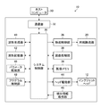
図2は制御系の概略構成が示されるブロック図である。図2に示されたインクジェット記録装置10は、システム制御部30が備えられている。
<Control system>
FIG. 2 is a block diagram showing a schematic configuration of the control system. The ink
システム制御部30は、CPU、ROM、及びRAMが備えられる構成が適用可能である。なお、CPUはCentral Processing Unitの省略語である。ROMはRead Only Memoryの省略語である。RAMはRandom Access Memoryの省略語である。
The
システム制御部30は、インクジェット記録装置10の各部を統括的に制御する全体制御部として機能する。また、システム制御部30は、各種演算処理を行う演算部として機能する。
The
更に、システム制御部30は、インクジェット記録装置10に具備される記憶装置へのデータの書き込み、及び記憶装置からのデータの読み出しを制御するメモリーコントローラとして機能する。
Further, the
図2に示されたインクジェット記録装置10は、通信部32が備えられている。通信部32は、図示されない通信インターフェースが備えられている。通信部32は通信インターフェースと接続されたホストコンピュータ33との間でデータの送受信を行うことができる。
The ink
画像メモリ34は、入力画像データを含む各種データの一時記憶部として機能する。画像メモリ34は、システム制御部30を通じてデータの読み書きが行われる。通信部32を介してホストコンピュータ33から取り込まれた画像データは、一旦画像メモリ34に格納される。
The
図2に示されたインクジェット記録装置10は、搬送制御部36が備えられている。搬送制御部36は、用紙搬送部20の動作を制御する。搬送制御部36は、図1に示された用紙18の搬送開始、用紙18の搬送停止、及び用紙18の搬送速度を制御する。
The ink
図2に示されたインクジェット記録装置10は、画像処理部38が備えられている。画像処理部38は、通信部32を介して取得された入力画像データに対して、色分解処理、色変換処理、補正処理、及びハーフトーン処理を施してドットデータを生成する。
The ink
すなわち、画像処理部38は、色分解処理部、色変換処理部、補正処理部、及びハーフトーン処理部が備えられている。なお、色分解処理部、色変換処理部、補正処理部、及びハーフトーン処理部の図示は省略される。
That is, the
色分解処理部では、入力画像データに対して色分解処理が施される。例えば、入力画像データがRGBで表されている場合、入力画像データがR、G、及びBの色ごとのデータに分解される。ここで、Rは赤を表す。Gは緑を表す。Bは青を表す。 In the color separation processing unit, color separation processing is performed on the input image data. For example, when the input image data is expressed in RGB, the input image data is decomposed into data for each of R, G, and B colors. Here, R represents red. G represents green. B represents blue.
色変換処理部では、R、G、及びBに分解された色ごとの画像データを、インク色に対応するC、M、Y、Kに変換される。ここで、Cはシアンを表す。Mはマゼンタを表す。Yはイエローを表す。Kはブラックを表す。 The color conversion processing unit converts the image data for each color separated into R, G, and B into C, M, Y, and K corresponding to the ink colors. Here, C represents cyan. M represents magenta. Y represents yellow. K represents black.
補正処理部では、C、M、Y、及びKに変換された色ごとの画像データに対して補正処理が施される。補正処理の例として、ガンマ補正処理、濃度むら補正処理、又は異常記録素子補正処理などが挙げられる。 In the correction processing unit, correction processing is performed on the image data for each color converted into C, M, Y, and K. Examples of the correction processing include gamma correction processing, density unevenness correction processing, abnormal recording element correction processing, and the like.
ハーフトーン処理部では、例えば、0から255といった多階調数で表された画像データが、二値、又は入力画像データの階調数未満の三値以上の多値で表されるドットデータに変換される。 In the halftone processing unit, for example, image data represented by a multi-gradation number such as 0 to 255 is converted into dot data represented by a binary or multi-value of three or more values less than the number of gradations of the input image data. Converted.
ハーフトーン処理部では、予め決められたハーフトーン処理規則が適用される。ハーフトーン処理規則の例として、ディザ法、又は誤差拡散法などが挙げられる。ハーフトーン処理規則は、画像記録条件、又は画像データの内容等に応じて変更されてもよい。 In the halftone processing unit, a predetermined halftone processing rule is applied. Examples of the halftone processing rule include a dither method or an error diffusion method. The halftone processing rule may be changed according to image recording conditions, the contents of image data, or the like.
図2に示されたインクジェット記録装置10は、波形生成部40、波形記憶部42、及びヘッド駆動部44が備えられている。波形生成部40は、インクジェットヘッド12に具備される吐出素子に供給される駆動電圧の波形である駆動波形を生成する。波形生成部40が用いられて生成された駆動波形は波形記憶部42に記憶される。なお、図2では吐出素子の図示は省略される。
The ink
図2に示された波形生成部40に代わり、装置外部で生成された駆動波形が入力される波形入力部を備えてもよい。波形入力部が用いられて入力された駆動波形は、波形記憶部42に記憶される。
Instead of the
波形記憶部42からの駆動波形を表す駆動波形データの読み出しは、駆動波形取得部が用いられた駆動波形取得の一態様である。
Reading of drive waveform data representing a drive waveform from the
ヘッド駆動部44は、インクジェットヘッド12に具備される複数の吐出素子のそれぞれに対して供給される駆動電圧を生成する駆動電圧生成部として機能する。また、ヘッド駆動部44は、インクジェットヘッド12に具備される複数の吐出素子のそれぞれに対して駆動電圧を供給する駆動電圧供給部として機能する。
The
ここで、駆動電圧の供給とはヘッド駆動部44の動作を表している。ヘッド駆動部44の詳細は後述される。
Here, the supply of the drive voltage represents the operation of the
図2に示されたインクジェット記録装置10は、パラメータ記憶部46、及びプログラム格納部48が備えられている。
The ink
パラメータ記憶部46は、インクジェット記録装置10に使用される各種パラメータが記憶される。パラメータ記憶部46に記憶されている各種パラメータは、システム制御部30を介して読み出され、装置各部に設定される。
The
プログラム格納部48は、インクジェット記録装置10の各部に使用されるプログラムが格納される。プログラム格納部48に格納されている各種プログラムは、システム制御部30を介して読み出され、装置各部において実行される。
The program storage unit 48 stores a program used for each unit of the
図2に示されたインクジェット記録装置10は、検出情報取得部49が備えられている。検出情報取得部49は、短絡検出における検出情報を取得する。短絡検出における検出情報の取得には、公知のデータ通信が適用可能である。
The
公知のデータ通信の例として、有線形式のデータ通信、及び無線形式のデータ通信が挙げられる。検出情報が記憶される記憶素子が用いられる態様も可能である。 Examples of known data communication include wired data communication and wireless data communication. A mode in which a storage element in which detection information is stored is also possible.
なお、図2には機能ごとに各部が列挙されている。図2に示された各部は適宜、統合、分離、兼用、又は省略が可能である。また、図2に示された各部はハードウエアとソフトウエアとを適宜組み合わせて構成することができる。 In FIG. 2, each part is listed for each function. Each part shown in FIG. 2 can be appropriately integrated, separated, combined, or omitted. Further, each unit shown in FIG. 2 can be configured by appropriately combining hardware and software.
<ヘッド駆動部の説明>
図3はヘッド駆動部の概略構成が示されるブロック図である。図3に示されたヘッド駆動部44は、ヘッドコントローラ50、デジタルアナログ変換回路52、増幅回路54、シフトレジスタ56、ラッチ回路58、及びレベル変換回路60が備えられている。なお、図3に示されたデジタルアナログ変換回路52のDAのDはデジタルを表している。また、DAのAはアナログを表している。
<Description of head drive unit>
FIG. 3 is a block diagram showing a schematic configuration of the head driving unit. The
ヘッドコントローラ50は、図2に示された波形記憶部42に記憶されている駆動波形を読み出し、駆動波形を表すデジタル信号をデジタルアナログ変換回路52へ送出する。
The
デジタルアナログ変換回路52は、デジタル信号の駆動波形をアナログ信号の駆動波形へ変換する。アナログ信号に変換された駆動波形は、増幅回路54へ送出される。
The digital-
増幅回路54は、アナログ形式の駆動波形を電圧増幅し、かつ、電流増幅して駆動電圧を生成する。増幅回路54において、電圧増幅、及び電流増幅されて生成された駆動電圧は、各吐出素子68の駆動電極に電気接続される各スイッチ素子62の駆動電圧入力端子へ送出される。
The amplifying
また、ヘッドコントローラ50は、シリアル形式の印字信号をクロック信号と同期してシフトレジスタ56へ送出する。更に、ヘッドコントローラ50は、ラッチ信号をラッチ回路58へ送出する。
The
シフトレジスタ56は、ヘッドコントローラ50から送出された印字信号であり、駆動波形に含まれる複数の波形要素の中から一つ以上の波形要素を選択する際に使用される印字信号が記憶される。シフトレジスタ56に記憶された印字信号は、ラッチ信号に基づいてラッチ回路58へ読み出される。
The
ラッチ回路58は、シフトレジスタ56から読み出された印字信号をレベル変換回路60へ送出する。レベル変換回路60は、ラッチ回路58から送出された印字信号をスイッチ素子62に適用可能な電圧に変換する。
The
レベル変換回路60が用いられて変換された印字信号に基づき、駆動波形に含まれる複数の波形要素の中から一つ以上の波形要素が選択される。複数の波形要素は、インクの吐出量に対応している。例えば、駆動波形に三種類の波形要素が含まれる場合、インクの吐出量を三段階に変化させることが可能である。
One or more waveform elements are selected from a plurality of waveform elements included in the drive waveform based on the print signal converted by using the
スイッチ素子集積回路64は、複数のスイッチ素子62が備えられている。スイッチ素子集積回路64は、ヘッドコントローラ50から送出されるイネーブル信号、及びセレクト信号が用いられて各スイッチ素子62のオンオフが切り替えられる。
The switch element integrated
図3に示されたヘッド駆動部44は、各吐出素子68のそれぞれと電気接続される複数のスイッチ素子62に対して各吐出素子68に共通の駆動電圧を送出する。各スイッチ素子62は、電気接続される吐出素子68の吐出タイミングを表す駆動信号、及びインク吐出量に対応する駆動信号に基づいてオンとされることで、各吐出素子68へそれぞれの吐出タイミングにおいて、各吐出素子68のそれぞれのインク吐出量に対応する駆動電圧が供給される。
The
なお、図3が用いられて説明されたインクジェットヘッド12の駆動方式は一例であり、例えば、吐出素子数が比較的少ないインクジェットヘッドでは、吐出素子ごとに駆動電圧が生成される方式が適用可能である。
Note that the driving method of the
図3には機能ごとに各部が列挙されている。図3に示された各部は適宜、統合、分離、兼用、又は省略が可能である。また、図3に示された各部はハードウエアとソフトウエアとを適宜組み合わせて構成することができる。 In FIG. 3, each part is listed for each function. Each part shown in FIG. 3 can be integrated, separated, combined, or omitted as appropriate. Each unit shown in FIG. 3 can be configured by appropriately combining hardware and software.
<吐出素子の説明>
図4は吐出素子の構成例が示される断面図である。図4は、インク吐出の最小単位である吐出素子68の立体構造が示される断面図である。図4に示された吐出素子68は、ノズル部、及び圧電素子88が備えられている。ノズル部は、ノズル開口80、圧力室84、振動板86、及び供給口90が含まれる。
<Description of ejection element>
FIG. 4 is a cross-sectional view showing a configuration example of the ejection element. FIG. 4 is a cross-sectional view showing a three-dimensional structure of the
ノズル開口80はノズルプレート82に形成される。ノズルプレート82の振動板86と反対側の面は液体吐出面である。ノズル開口80は圧力室84と連通される。圧力室84はノズル開口80から吐出させるインクが一時的に貯留される。
The
圧力室84は、供給口90を介して共通流路92と連通される。供給口90は、圧力室84と共通流路92とを連通させる流路であり、圧力室84のノズル開口80側の流出口の直径未満の直径を有している。
The
供給口90は圧力室84の供給側の絞りとして機能している。共通流路92は図示されないインク流路を介して、図1に示されたチューブ14と連通される。圧力室84のノズル開口80と反対側の面には振動板86が接合される。振動板86の圧力室84と反対側の面には圧電素子88が接合される。
The
圧電素子88は、上部電極94、圧電体98、及び下部電極96が備えられている。圧電素子88は、上部電極94と下部電極96との間に圧電体98が挟まれた構造を有している。下部電極96は振動板86と兼用可能である。圧電素子は圧力発生素子の一態様である。
The
図示は省略されるが、各ノズル開口80に対応して設けられている圧力室84は、その平面形状が概略正方形となっており、対角線上の両隅部の一方にノズル開口80への流出口が設けられ、他方に供給インクの流入口である供給口90が設けられている。
Although not shown, the
なお、圧力室84の平面形状は、正方形に限定されない。圧力室84の平面形状は、菱形、長方形などの四角形、五角形、六角形その他の多角形、円形、楕円形など、多様な形態が適用可能である。
The planar shape of the
吐出素子68は、入力画像データから生成されるドットデータに応じて各ノズル開口80に対応した圧電素子88の駆動を制御することにより、ノズル開口80から液滴状のインクを吐出させることができる。
The
図1に示された用紙18を一定の速度で用紙搬送方向に搬送させながら、用紙18の搬送速度に合わせて、図4に示された各ノズル開口80からの液滴状のインクの吐出タイミングを制御することによって、用紙18の上に所望の画像が形成される。
While ejecting the
図4に示された吐出素子68は、複数のキャビティプレートを積層させた構造が適用可能である。図4に示された吐出素子68は、ノズル開口80が形成されるノズルプレート82、圧力室84、供給口90、共通流路92等が形成される流路プレート99、振動板86、及び圧電素子88を、ノズルプレート82、流路プレート99、振動板86、及び圧電素子88の順に積層させた構造を有している。流路プレート99は更に細分化されていてもよい。
The
本実施形態では、圧力室84に貯留されるインクを加圧する手段として圧電素子88が適用される圧電方式が例示されているが、圧力室84の内部にインクを加熱するヒータを備え、インクの膜沸騰現象を利用してインクを加圧するサーマル方式が適用可能である。なお、ヒータは圧力発生素子の一態様である。
In the present embodiment, a piezoelectric method in which the
[第一実施形態に係る短絡検出の説明]
次に、第一実施形態に係る短絡検出について説明する。
[Description of short circuit detection according to first embodiment]
Next, short circuit detection according to the first embodiment will be described.
<インクジェットヘッドの構造例>
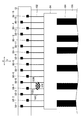
図5はインクジェットヘッドの液体吐出面の透視平面図である。説明を簡単にするために、図5には、複数の吐出素子68のうち十六個の吐出素子68が示されている。
<Example structure of inkjet head>
FIG. 5 is a perspective plan view of the liquid ejection surface of the inkjet head. For ease of explanation, FIG. 5 shows sixteen
吐出素子を表す符号68に付された副番号は、十六個の吐出素子68の識別番号であり、用紙幅方向における配置順に対応している。なお、以下の説明において、図5に示された吐出素子68−1から吐出素子68−16を区別する必要がない場合は、吐出素子68と記載される。また、図5に示された吐出素子68は、図4に示されたノズル開口80、又は圧電素子88と読み替えが可能である。
The sub-number given to the
図5に示されたインクジェットヘッド12は、複数の吐出素子68が用紙搬送方向について二列に配置されている。一方の列に属する吐出素子68と、他方の列に属する吐出素子68とは、それぞれ用紙搬送方向について等間隔に配置されている。
In the
例えば、一方の列に属する吐出素子68は、吐出素子68−1、吐出素子68−3、吐出素子68−5、吐出素子68−7、吐出素子68−9、吐出素子68−11、吐出素子68−13、及び吐出素子68−15である。
For example, the
また、他方の列に属する吐出素子68は、吐出素子68−2、吐出素子68−4、吐出素子68−6、吐出素子68−8、吐出素子68−10、吐出素子68−12、吐出素子68−14、及び吐出素子68−16である。
The
図5に示された吐出素子68−1から吐出素子68−16を用紙幅方向について投影させた場合の用紙幅方向における吐出素子68の配置間隔PNX1は等間隔である。また、吐出素子68−1から吐出素子68−16を用紙幅方向について投影させた場合の吐出素子68の配置間隔PNX1は、用紙幅方向における各列の吐出素子68の配置間隔PNX2の二分の一である。
Arrangement interval P NX1 discharge device 68 the ejection elements 68-16 from the discharge device 68 - shown in FIG. 5 in the paper width direction when is projected for the sheet width direction is equally spaced. The arrangement interval P NX1 of
画像の最大解像度が600ドット毎インチの場合、用紙幅方向における各列の吐出素子の配置間隔PNX2は84マイクロメートルである。また、図5に示された吐出素子68−1から吐出素子68−16を用紙幅方向について投影させた場合の用紙幅方向における吐出素子68の配置間隔PNX1は42マイクロメートルである。
When the maximum resolution of the image is 600 dots per inch, the arrangement interval P NX2 of the ejection elements in each row in the paper width direction is 84 micrometers. Further, when the ejection elements 68-1 to 68-16 shown in FIG. 5 are projected in the paper width direction, the arrangement interval P NX1 of the
用紙搬送方向における吐出素子68の配置間隔PNYは84マイクロメートルである。なお、この配置間隔PNX1、配置間隔PNX2、及び配置間隔PNYを表す数値は、小数点第一位が四捨五入された数値である。
The arrangement interval P NY of the
図5に示された複数の吐出素子68の配置は、マトリクス配置の一態様である。複数の吐出素子68がマトリクス配置される他の例として、インクジェットヘッド12の長手方向に沿う行方向、及びインクジェットヘッド12の長手方向と交差する斜めの列方向に沿って複数の吐出素子68が配置される例が挙げられる。
The arrangement of the plurality of
なお、インクジェットヘッド12の長手方向は、インクジェットヘッド12の使用状態における用紙幅方向に相当する。インクジェットヘッド12の短手方向は、インクジェットヘッド12の使用状態における用紙搬送方向に相当する。
The longitudinal direction of the
以下の説明についても同様である。以下の説明において、便宜上、インクジェットヘッド12の長手方向は符号Xが付される。また、インクジェットヘッド12の短手方向は符号Yが付される。図6から図8についても同様である。
The same applies to the following description. In the following description, for the sake of convenience, the longitudinal direction of the
複数のヘッドモジュールを備え、複数のヘッドモジュールがインクジェットヘッドの長手方向について並べられた構造を有するインクジェットヘッドが適用されてもよい。複数のヘッドモジュールは一列に並べられてもよいし、二列以上に並べられてもよい。 An inkjet head including a plurality of head modules and having a structure in which a plurality of head modules are arranged in the longitudinal direction of the inkjet head may be applied. The plurality of head modules may be arranged in a line, or may be arranged in two or more lines.
ヘッドモジュールは、インクジェットヘッド12の長手方向に対して傾きを有する方向に沿った長辺側の端面と、インクジェットヘッド12の短手方向に対して傾きを有する方向に沿った短辺側の端面とを有する平行四辺形の平面形状が適用可能である。
The head module has a long side end surface along a direction inclined with respect to the longitudinal direction of the
複数の吐出素子68がマトリクス配置される他の例として、長辺側の端面の向に沿う行方向、及び短辺側の端面の方向に沿う列方向について、複数のノズル開口80が配置される例が挙げられる。
As another example in which the plurality of
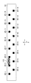
図6は吐出素子への電気配線が模式的に示された説明図である。図6では図5に示された吐出素子68−1から吐出素子68−16に代わり、吐出素子68−1から吐出素子68−16のそれぞれに対応する圧電素子88−1から圧電素子88−16が示されている。 FIG. 6 is an explanatory diagram schematically showing electrical wiring to the ejection elements. In FIG. 6, instead of the ejection elements 68-1 to 68-16 shown in FIG. 5, the piezoelectric elements 88-1 to 88-16 corresponding to the ejection elements 68-1 to 68-16 respectively. It is shown.
なお、圧電素子を表す符号88に付された副番号は、図5に示された吐出素子を表す符号68に付された副番号と同様に、圧電素子88の識別番号であり、用紙幅方向における配置順に対応している。なお、以下の説明において、図6に示された圧電素子88−1から圧電素子88−16を区別する必要がない場合は、圧電素子88と記載される。電気配線には、電極、パッド、又はスルーホールなどが含まれていてもよい。
Note that the sub-number assigned to the
インクジェットヘッド12は、フレキシブル基板100が用いられて、図2、及び図3に示されたヘッド駆動部44が搭載される電気回路基板と電気接続される。フレキシブル基板100は、図3に示されたスイッチ素子集積回路64が搭載されている。なお、電気回路基板の図示は省略される。
The
図6に示されたフレキシブル基板100は、スイッチ素子集積回路64の駆動電圧出力端子と電気接続され、かつ、スイッチ素子集積回路64の駆動電圧出力端子と機械的に接合される電極と、各圧電素子88の上部電極とを電気接続させる電気配線102が形成されている。図6では、各圧電素子88の上部電極の図示は省略される。圧電素子88の上部電極は図4に符号94が付されて図示される。
The
なお、図6では、図示された複数の電気配線102のうち一本のみに符号が付されている。また、図6ではスイッチ素子集積回路64の駆動電圧出力端子の図示は省略される。スイッチ素子集積回路64の駆動電圧出力端子は図8に符号65−1から65−16が付されて図示される。
In FIG. 6, only one of the plurality of
図6に示されたフレキシブル基板100は、図3に示されたヘッド駆動部44からスイッチ素子集積回路64へ伝送される駆動電圧の電気配線104が形成されている。なお、図6では、図示された複数の電気配線104のうち一本のみに符号が付されている。
The
<吐出素子の短絡の説明>
図7は電気配線が短絡している場合が模式的に示された説明図である。図7に示されるインクジェットヘッド12は、圧電素子88−4に電気接続される電気配線102A、及び圧電素子88−5に電気接続される電気配線102Bに導電物110が接触することで短絡している。各吐出素子68と電気接続される電気配線102の短絡は、吐出素子68の短絡と同義である。
<Explanation of short circuit of discharge element>
FIG. 7 is an explanatory view schematically showing a case where the electrical wiring is short-circuited. The
図7に示されるように、圧電素子88−4に電気接続される電気配線102Aと、圧電素子88−5に電気接続される電気配線102Bとが短絡していると、圧電素子88−4を駆動させたタイミングにおいて、圧電素子88−5も駆動させてしまう。
As shown in FIG. 7, when the
そうすると、圧電素子88−4が具備される吐出素子68−4からインクを吐出させるタイミングにおいて、圧電素子88−5が具備される吐出素子68−5からもインクを吐出させてしまう。 Then, at the timing when ink is ejected from the ejection element 68-4 provided with the piezoelectric element 88-4, ink is also ejected from the ejection element 68-5 provided with the piezoelectric element 88-5.
また、圧電素子88−5を駆動させた場合にも、圧電素子88−5が具備される吐出素子68−5からインクを吐出させるタイミングにおいて、圧電素子88−4が具備される吐出素子68−4からもインクを吐出させてしまう。このような状態では、本来形成されるべき画像とは異なる画像が形成されてしまう。 Further, even when the piezoelectric element 88-5 is driven, the ejection element 68- provided with the piezoelectric element 88-4 is ejected from the ejection element 68-5 provided with the piezoelectric element 88-5. Ink is ejected from 4 as well. In such a state, an image different from the image that should originally be formed is formed.
図8はスイッチ素子集積回路の駆動電圧出力端子が短絡している場合が模式的に示された説明図である。図8はスイッチ素子集積回路64を透視して駆動電圧出力端子65−1から駆動電圧出力端子65−16を見た図である。なお、以下の説明において、図8に示された駆動電圧出力端子65−1から駆動電圧出力端子65−16を区別する必要がない場合は、駆動電圧出力端子65と記載される。
FIG. 8 is an explanatory diagram schematically showing the case where the drive voltage output terminal of the switch element integrated circuit is short-circuited. FIG. 8 is a diagram of the drive voltage output terminal 65-16 viewed from the drive voltage output terminal 65-1 through the switch element integrated
図8に示されたスイッチ素子集積回路64は、駆動電圧出力端子65−3、及び駆動電圧出力端子65−5に導電物112が付着することで短絡している。各吐出素子68と電気接続される駆動電圧出力端子65の短絡は、吐出素子68の短絡と同義である。
The switch element integrated
図8に示されたスイッチ素子集積回路64において、駆動電圧出力端子65−3と、駆動電圧出力端子65−5とが短絡している場合にも、本来形成されるべき画像とは異なる画像が形成されてしまう。
In the switch element integrated
本実施形態に示されるように、電気配線、及び駆動電圧出力端子が高密度に配置されている場合は、隣接する電気配線間、又は隣接する駆動電圧出力端子間の短絡が発生しやすい。 As shown in the present embodiment, when the electrical wiring and the drive voltage output terminals are arranged at high density, a short circuit is likely to occur between adjacent electrical wirings or between adjacent drive voltage output terminals.
図8に示された駆動電圧出力端子65の例として、ASIC化されたスイッチ素子集積回路64のボンディング部が挙げられる。なお、ASICは、Application Specific Integrated Circuitの省略語である。
As an example of the drive voltage output terminal 65 shown in FIG. 8, there is a bonding portion of the ASIC switch element integrated
駆動電圧出力端子65と同様に、駆動電圧出力端子65と電気的に接続され、かつ、機械的に接合される電極もまた、短絡が発生しやすい。隣接する電極が短絡している場合も、本来形成されるべき画像とは異なる画像が形成されてしまう。 Similarly to the drive voltage output terminal 65, an electrode that is electrically connected to the drive voltage output terminal 65 and mechanically joined is also likely to cause a short circuit. Even when adjacent electrodes are short-circuited, an image different from the image that should be originally formed is formed.
ここで、隣接する電気配線には、図7に示された圧電素子88−3に電気接続される電気配線102Cと圧電素子88−5に電気接続される電気配線102Bとのように、フレキシブル基板100において非隣接であっても、インクジェットヘッド12の内部で隣接している場合が含まれる。
Here, the adjacent electrical wiring includes flexible boards such as the
また、隣接する駆動電圧出力端子には、図8に示された駆動電圧出力端子65−3と駆動電圧出力端子65−4のように、インクジェットヘッド12の長手方向と直交する方向、又はインクジェットヘッド12の長手方向と交差する斜め方向に隣接する場合が含まれる。
Further, adjacent drive voltage output terminals include a direction orthogonal to the longitudinal direction of the
本来形成されるべき画像が形成されていない場合に、形成された画像を許容しないとする対応が可能である。一方、短絡が発生している吐出素子が特定されれば、吐出素子間の短絡の対処のレベルを上げることが可能である。 When the image that should originally be formed is not formed, it is possible to cope with not allowing the formed image. On the other hand, if a discharge element in which a short circuit has occurred is identified, it is possible to increase the level of countermeasures against a short circuit between the discharge elements.
短絡の対処のレベルを上げる例として、短絡が発生している吐出素子に対して非使用処理がされることが挙げられる。短絡が発生している吐出素子に対して非使用処理がされることで、インクジェットヘッドの使用が可能である。また、短絡が発生している吐出素子の数に応じて、インクジェットヘッドの交換が必要であるか否かの判断が可能である。 As an example of raising the level of countermeasures against a short circuit, a non-use process may be performed on a discharge element in which a short circuit has occurred. The inkjet head can be used by performing non-use processing on the ejection element in which a short circuit has occurred. Further, it is possible to determine whether or not the ink jet head needs to be replaced depending on the number of ejection elements in which a short circuit has occurred.
更に、短絡の位置が特定されることにより、インクジェットヘッドの生産プロセスの改善を図ることが可能となる。以下に、短絡検出について詳細に説明する。 Furthermore, by specifying the position of the short circuit, it is possible to improve the production process of the inkjet head. Hereinafter, the short circuit detection will be described in detail.
<第一実施形態に係る短絡検出用駆動電圧の説明>
図9は第一実施形態に係る短絡検出用駆動電圧の説明図である。なお、図9における横軸は期間である。期間の単位はマイクロ秒である。マイクロは10−6を表している。また、図9の縦系列は電圧である。電圧の単位はボルトである。図10、図11、図16、及び図17についても同様である。また、以下の説明における図示されない吐出素子は、図4に示された吐出素子68である。
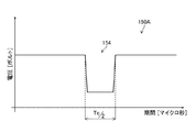
<Description of Drive Voltage for Short Circuit Detection According to First Embodiment>
FIG. 9 is an explanatory diagram of a short-circuit detection drive voltage according to the first embodiment. In addition, the horizontal axis in FIG. 9 is a period. The unit of period is microseconds. Micro represents 10 −6 . The vertical series in FIG. 9 is voltage. The unit of voltage is volts. The same applies to FIG. 10, FIG. 11, FIG. 16, and FIG. In the following description, an ejection element (not shown) is the
図9に示された駆動波形120は、第一波形要素122、及び第二波形要素124が含まれている。駆動波形120において、第一波形要素122、及び第二波形要素124は、時間的に重ならない。
The
また、駆動波形120は、第一波形要素122の始期から第二波形要素124の始期までの期間は吐出素子の共振周期Tcとされる。また、第一波形要素122のパルス幅は吐出素子の共振周期Tcの二分の一とされる。
In the
ここで、第一波形要素122のパルス幅は、第一波形要素122の始期から第一波形要素122の終期までの期間が適用可能である。
Here, as the pulse width of the
図10は第一波形要素の説明図である。図10に示された第一波形要素122から成る駆動波形120Aを有する第一駆動電圧は、単独で各吐出素子に印加されても各吐出素子からインクを吐出させることができない駆動電圧である。
FIG. 10 is an explanatory diagram of the first waveform element. The first drive voltage having the
駆動電圧の印加とは、吐出素子から見た駆動電圧の供給の結果を表している。各吐出素子と電気接続される電気配線に短絡、又は開放等の電気的異常は発生している場合は、図2に示されたヘッド駆動部44から供給されていない駆動電圧が印加されること、又はヘッド駆動部44から供給されるべき駆動電圧が印加されないことがあり得る。
The application of the drive voltage represents the result of supplying the drive voltage as viewed from the ejection element. When an electrical abnormality such as a short circuit or an open circuit has occurred in the electrical wiring electrically connected to each ejection element, a drive voltage not supplied from the
図11は第二波形要素の説明図である。図11に示された第二波形要素124から成る駆動波形120Bを有する第二駆動電圧は、単独で各吐出素子に印加されても各吐出素子からインクを吐出させることができない駆動電圧である。
FIG. 11 is an explanatory diagram of the second waveform element. The second drive voltage having the
吐出素子からインクを吐出させることができない駆動電圧の例として、吐出素子からインクを吐出させるために必要な電位差未満の電位差を有する駆動電圧が挙げられる。 As an example of the drive voltage in which ink cannot be ejected from the ejection element, there is a drive voltage having a potential difference less than the potential difference necessary for ejecting ink from the ejection element.
図9に示された駆動波形120を有する駆動電圧を用意しておく。短絡検出対象の吐出素子に対して、図10に示された第一波形要素122から成る駆動波形120Aを有する第一駆動電圧が供給される。
A drive voltage having the
また、短絡検出対象の吐出素子と短絡が疑われる吐出素子に対して、図11に示された第二波形要素124から成る駆動波形120Bを有する第二駆動電圧が供給される。以下、短絡検出対象の吐出素子は第一吐出素子と記載される。また、短絡検出対象の吐出素子と短絡が疑われる吐出素子は第二吐出素子と記載される。
Further, a second drive voltage having a
短絡検出対象の吐出素子と短絡が疑われる吐出素子は、短絡検出対象の吐出素子の隣接位置に配置される吐出素子が適用可能である。短絡検出対象の吐出素子の隣接位置は、インクジェットヘッド12の長手方向における隣接位置でもよい。
As the ejection element suspected of being short-circuited with the ejection element to be detected as a short circuit, an ejection element disposed at a position adjacent to the ejection element to be detected as a short circuit can be applied. The adjacent position of the ejection element to be detected as a short circuit may be an adjacent position in the longitudinal direction of the
短絡検出対象の吐出素子の隣接位置は、インクジェットヘッド12の長手方向と直交する方向であるインクジェットヘッド12の短手方向における隣接位置でもよいし、インクジェットヘッド12の長手方向、及びインクジェットヘッド12の短手方向と交差する斜め方向の隣接位置でもよい。
The adjacent position of the ejection element subject to short circuit detection may be the adjacent position in the short direction of the
第一吐出素子と第二吐出素子との短絡が発生していない場合は、第一吐出素子、及び第二吐出素子のいずれからもインクが吐出されない。一方、第一吐出素子と第二吐出素子との短絡が発生している場合は、第一吐出素子、及び第二吐出素子のいずれからもインクが吐出される。 When the short circuit between the first ejection element and the second ejection element does not occur, ink is not ejected from either the first ejection element or the second ejection element. On the other hand, when a short circuit occurs between the first ejection element and the second ejection element, ink is ejected from both the first ejection element and the second ejection element.
第一吐出素子と第二吐出素子との短絡が発生していない場合の第一吐出素子、及び第二吐出素子の吐出の有無、並びに第一吐出素子と第二吐出素子との短絡が発生している場合の第一吐出素子、及び第二吐出素子の吐出の有無が[表1]に示される。 When the first discharge element and the second discharge element are not short-circuited, the first discharge element and the presence or absence of discharge of the second discharge element, and the first discharge element and the second discharge element are short-circuited. Table 1 shows whether the first ejection element and the second ejection element are ejected or not.

[表1]における任意の正常吐出素子は、第一吐出素子と第二吐出素子との短絡が発生していない場合の第一吐出素子である。また、[表1]における他の正常吐出素子は、第一吐出素子と第二吐出素子との短絡が発生していない場合の第二吐出素子である。 The arbitrary normal ejection elements in [Table 1] are the first ejection elements when the first ejection element and the second ejection element are not short-circuited. Further, the other normal ejection elements in [Table 1] are the second ejection elements when the first ejection element and the second ejection element are not short-circuited.
[表1]における短絡が発生している吐出素子は、第一吐出素子と第二吐出素子との短絡が発生している場合の第一吐出素子、及び第二吐出素子である。 The ejection elements in which the short circuit occurs in [Table 1] are the first ejection element and the second ejection element when the first ejection element and the second ejection element are short-circuited.
図9に示されるように、第一波形要素122の始期から第二波形要素124の始期までの期間が吐出素子の共振周期Tcとされることで、第一吐出素子と第二吐出素子との短絡が発生している場合に、第一吐出素子、及び第二吐出素子から吐出をさせ易くなる。
As shown in FIG. 9, the period from the start of the
すなわち、第一波形要素122から成る駆動波形120Aを有する第一駆動電圧が印加されることで、吐出されない程度にインクが加圧される。そして、第一波形要素122の始期から吐出素子の共振周期Tc経過の後に第二波形要素124から成る駆動波形120Bを有する第二駆動電圧が印加されることで、インクが吐出しやすいタイミングにおいてインクが加圧されるので、第一吐出素子、及び第二吐出素子からインクを吐出させ易くなる。
That is, by applying a first drive voltage having a
図9に示された第一波形要素122の始期から第二波形要素124の始期までの期間は、吐出素子の共振周期Tcに定数α1を乗算して算出される下限値、吐出素子の共振周期Tcに定数α2を乗算して算出される上限値を有する期間とすることが可能である。
The period from the beginning of the
第一波形要素122の始期から第二波形要素124の始期までの期間は、第一駆動電圧の始期から第二駆動電圧の始期までの期間に相当する。
A period from the start of the
定数α1、及び定数α2は、第一吐出素子と第二吐出素子との短絡が発生している場合に、第一吐出素子、及び第二吐出素子からインクを吐出させることができるという条件から決められる。 The constant α 1 and the constant α 2 are conditions that ink can be ejected from the first ejection element and the second ejection element when a short circuit occurs between the first ejection element and the second ejection element. It is decided from.
なお、定数α1<定数α2の関係を有している。例えば、定数α1、及び定数α2は、0.5<α1<1.0、かつ、1.0<α2<1.5としてもよい。 It should be noted that there is a relationship of constant α 1 <constant α 2 . For example, the constant α 1 and the constant α 2 may be 0.5 <α 1 <1.0 and 1.0 <α 2 <1.5.
<インクの吐出状態の観察>
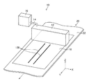
図12は第一実施形態に係るインクの吐出状態の観察の一例の説明図である。図12に示される例では、第一吐出素子に対して第一駆動電圧が供給され、第二吐出素子に第二駆動電圧が供給される期間において、撮像装置130、及び光源132が用いられて、インクジェットヘッド12から吐出させた液滴状のインク134が通過する液体通過領域136が撮像される。
<Observation of ink discharge state>
FIG. 12 is an explanatory diagram of an example of observation of the ink ejection state according to the first embodiment. In the example shown in FIG. 12, the
撮像装置130の一例として、イメージセンサを備えた撮像装置が挙げられる。イメージセンサは、CCDイメージセンサ、又はCMOSイメージセンサを適用することが可能である。なお、CCDはCharge Coupled Deviceの省略語である。CMOSはComplementary Metal-Oxide Semiconductorの省略語である。
An example of the
光源は、液体通過領域136に対して照明光を照射させる。照明光は撮像装置130の撮像条件を満たしていればよく、照明光の種類は限定されない。
The light source irradiates the
撮像装置130が用いられて液滴状のインク134が撮像されている場合は、第一吐出素子と第二吐出素子との短絡が発生していると判断することが可能である。一方、撮像装置130が用いられて液滴状のインク134が撮像されていない場合は、第一吐出素子と第二吐出素子との短絡が発生していないと判断することが可能である。
When the
撮像装置130が用いられて取得された撮像データは、図2に示された検出情報取得部49が用いられて取得される。図12に示された撮像装置130から図2に示された検出情報取得部49への撮像データの通信は、公知のデータ通信を適用することが可能である。検出情報取得部49は、撮像データ取得部の一態様である。
The imaging data acquired using the
図12に示されたインクの吐出状態の観察は、インクジェットヘッド12を描画の際の配置よりも上方向に移動させて、液体通過領域136をより広げた状態で実行されるとよい。
The observation of the ink ejection state shown in FIG. 12 may be performed in a state where the
図13は第一実施形態に係るインクの吐出状態の観察の他の例の説明図である。図13に示される例では、用紙18を用紙搬送方向へ搬送させて、第一吐出素子に対して第一駆動電圧が供給され、第二吐出素子に対して第二駆動電圧が供給される。
FIG. 13 is an explanatory diagram of another example of observation of the ink ejection state according to the first embodiment. In the example shown in FIG. 13, the
第一吐出素子と第二吐出素子との短絡が発生している場合は、図13に示されるドット列138が形成される。一方、第一吐出素子と第二吐出素子との短絡が発生していない場合は、図13に示されるドット列138が形成されない。
When a short circuit occurs between the first ejection element and the second ejection element, the
すなわち、用紙18にドット列138が形成されるか否かが観察されることで、第一吐出素子と第二吐出素子との短絡が発生しているか否かの判断が可能である。
That is, by observing whether or not the
用紙18に形成されたドット列138の有無の観察は、作業者の目視が適用可能である。作業者の目視が用いられて、用紙18に形成されたドット列138の有無が観察される場合は、作業者が入力した観察情報が図2に示された検出情報取得部49が用いられて取得される。検出情報取得部49は観察結果情報取得部の一態様である。
The operator's visual observation can be applied to the observation of the presence or absence of the
用紙18に形成されたドット列138の有無の観察は、撮像装置による撮像が適用可能である。撮像装置が用いられて用紙18に形成されたドット列138の有無が観察される場合は、撮像装置が用いられて得られた撮像データが、図2に示された検出情報取得部49が用いられて取得される。撮像装置には、先に説明された撮像装置130と同様の撮像装置が適用可能である。
For observation of the presence or absence of the
図14は図13に示されたインクの吐出状態の観察の変形例の説明図である。図14に示される変形例では、図13に示されたインクの吐出状態の観察に対して、第一吐出素子、及び第二吐出素子以外の正常な吐出素子が用いられた複数のドット列140の形成が追加されている。
FIG. 14 is an explanatory diagram of a modification of the observation of the ink ejection state shown in FIG. In the modification shown in FIG. 14, a plurality of
図14に示された複数のドット列140は、用紙幅方向について等間隔に形成される。例えば、百個の吐出素子が備えられるインクジェットヘッドの短絡検出では、十個の吐出素子ごとにドット列140が形成される駆動電圧が供給される。
The plurality of
すなわち、図14に示された複数のドット列140は、用紙18における目盛りとして機能する。複数のドット列140が形成されることで、第一吐出素子、及び第二吐出素子の位置の特定が容易とされる。
That is, the plurality of
以上説明したインクの吐出状態の観察では、第一吐出素子、及び第二吐出素子について吐出の有無が観察される態様が例示されているが、少なくとも第一吐出素子の吐出の有無が観察されることで、第一吐出素子と第二吐出素子との間の短絡検出が可能である。 In the above-described observation of the ink ejection state, the mode in which the presence or absence of ejection is observed for the first ejection element and the second ejection element is exemplified, but at least the presence or absence of ejection of the first ejection element is observed. Thus, a short circuit between the first ejection element and the second ejection element can be detected.
<短絡検出方法の手順>
図15は第一実施形態に係る短絡検出方法の手順の流れが示されたフローチャートである。短絡検出が開始されると、第一吐出素子設定工程S10において、第一吐出素子が設定される。また、第二吐出素子設定工程S12において、第二吐出素子が設定される。
<Short circuit detection procedure>
FIG. 15 is a flowchart showing the flow of the procedure of the short circuit detection method according to the first embodiment. When the short circuit detection is started, the first discharge element is set in the first discharge element setting step S10. In the second ejection element setting step S12, the second ejection element is set.
第一吐出素子設定工程S10において第一吐出素子が設定され、かつ、第二吐出素子設定工程S12において第二吐出素子が設定された後に、短絡検出用駆動電圧供給工程S14へ進む。 After the first discharge element is set in the first discharge element setting step S10 and the second discharge element is set in the second discharge element setting step S12, the process proceeds to the short-circuit detection drive voltage supply step S14.
短絡検出用駆動電圧供給工程S14では、図10に示された第一波形要素122から成る駆動波形120Aを有する第一駆動電圧が生成される。また、図15に示された短絡検出用駆動電圧供給工程S14では、図11に示された第二波形要素124から成る駆動波形120Bを有する第二駆動電圧が生成される。
In the short-circuit detection drive voltage supply step S14, a first drive voltage having a
図15に示された短絡検出用駆動電圧供給工程S14において、第一吐出素子に対して図10に示された第一波形要素122から成る駆動波形120Aを有する第一駆動電圧が供給される。また、図15に示された短絡検出用駆動電圧供給工程S14において、第二吐出素子に対して図11に示された第二波形要素124から成る駆動波形120Bを有する第二駆動電圧が供給された後に、図15に示された吐出状態観察工程S16へ進む。
In the short-circuit detection drive voltage supply step S14 shown in FIG. 15, the first drive voltage having the
第一吐出素子への第一駆動電圧の供給、及び第二吐出素子への第二駆動電圧の供給の順序は限定されない、第一吐出素子への第一駆動電圧の供給の後に第二吐出素子への第二駆動電圧の供給がされてもよい。一方、第二吐出素子への第二駆動電圧の供給の後に第一吐出素子への第一駆動電圧の供給がされてもよい。 The order of the supply of the first drive voltage to the first discharge element and the supply of the second drive voltage to the second discharge element is not limited, and the second discharge element after the supply of the first drive voltage to the first discharge element The second drive voltage may be supplied to the. On the other hand, the first drive voltage may be supplied to the first discharge element after the second drive voltage is supplied to the second discharge element.
吐出状態観察工程S16では、インクの吐出状態が観察される。吐出状態観察工程S16において、インクが吐出されないことを表す観察結果が取得された場合はNo判定となる。No判定の場合は終了判断工程S20へ進む。No判定の場合に、検出結果記憶工程S18に進む態様も可能である。 In the discharge state observation step S16, the ink discharge state is observed. In the ejection state observation step S16, if an observation result indicating that ink is not ejected is acquired, the determination is No. In the case of No determination, the process proceeds to the end determination step S20. In the case of No determination, a mode of proceeding to the detection result storing step S18 is also possible.
一方、吐出状態観察工程S16において、インクが吐出されたことを表す観察結果が取得された場合はYes判定となる。Yes判定の場合は検出結果記憶工程S18へ進む。 On the other hand, in the ejection state observation step S16, if an observation result indicating that ink has been ejected is acquired, a Yes determination is made. In the case of Yes determination, the process proceeds to the detection result storing step S18.
吐出状態観察工程S16において、図12に示された吐出状態の観察が適用される場合は、図15に示された短絡検出用駆動電圧供給工程S14において、第一吐出素子に対して図10に示された第一波形要素122から成る駆動波形120Aを有する第一駆動電圧が供給され、かつ、第二吐出素子に対して図11に示された第二波形要素124から成る駆動波形120Bを有する第二駆動電圧が供給される期間中に、図15に示された吐出状態観察工程S16へ進む。
In the discharge state observation step S16, when the observation of the discharge state shown in FIG. 12 is applied, in the short-circuit detection drive voltage supply step S14 shown in FIG. A first drive voltage having a
検出結果記憶工程S18では、第一吐出素子、及び第二吐出素子の識別情報が記憶される。検出結果記憶工程S18において、第一吐出素子、及び第二吐出素子の識別情報が記憶された後に、終了判断工程S20へ進む。 In the detection result storage step S18, identification information of the first ejection element and the second ejection element is stored. In the detection result storage step S18, after the identification information of the first discharge element and the second discharge element is stored, the process proceeds to the end determination step S20.
終了判断工程S20では、全ての第一吐出素子について短絡検出が終了しているか否かが判断される。終了判断工程S20において、全ての短絡検出対象の吐出素子について短絡検出が終了していると判断された場合は、短絡検出方法は終了される。 In the end determination step S20, it is determined whether or not the short circuit detection has been completed for all the first ejection elements. In the end determination step S20, when it is determined that the short circuit detection has been completed for all the discharge elements to be detected as a short circuit, the short circuit detection method is ended.
一方、終了判断工程S20において、全ての第一吐出素子について短絡検出が終了していないと判断された場合は、第一吐出素子設定工程S10へ進む。以下、全ての第一吐出素子について短絡検出が終了するまで、第一吐出素子設定工程S10から終了判断工程S20までの工程が繰り返し実行される。 On the other hand, if it is determined in the end determination step S20 that the short circuit detection has not been completed for all the first discharge elements, the process proceeds to the first discharge element setting step S10. Hereinafter, the processes from the first discharge element setting step S10 to the end determination step S20 are repeatedly performed until the short circuit detection is completed for all the first discharge elements.
検出結果記憶工程S18の後に、検出結果記憶工程S18において短絡が発生している吐出素子として記憶された第一吐出素子、及び第二吐出素子に対して非使用処理が施される非使用処理工程が追加されてもよい。 Non-use processing step in which non-use processing is performed on the first discharge element and the second discharge element stored as the discharge element in which a short circuit has occurred in the detection result storage step S18 after the detection result storage step S18. May be added.
非使用処理とは、処理対象の吐出素子がインクを吐出させない吐出素子とされる処理である。非使用処理の例として、処理対象の吐出素子が用いられて形成される画素に対して、最大階調値、又は最小階調値が固定値として入力される処理が挙げられる。 The non-use process is a process in which an ejection element to be processed is an ejection element that does not eject ink. As an example of the non-use process, there is a process in which the maximum gradation value or the minimum gradation value is input as a fixed value for a pixel formed by using the ejection element to be processed.
一つの第一吐出素子に対して複数の第二吐出素子が設定可能な場合は、第二吐出素子設定工程S12において、複数の第二吐出素子が設定されてもよい。一つの第一吐出素子に対して複数の第二吐出素子が設定可能な場合は、複数の第二吐出素子について一つずつ、第二吐出素子設定工程S12から終了判断工程S20までの工程が実行されてもよい。 When a plurality of second ejection elements can be set for one first ejection element, a plurality of second ejection elements may be set in the second ejection element setting step S12. When a plurality of second ejection elements can be set for one first ejection element, the processes from the second ejection element setting step S12 to the end determination step S20 are performed one by one for the plurality of second ejection elements. May be.
複数の第一吐出素子が存在する場合は、複数の第一吐出素子の一部、又は全部について、図15に示された短絡検出方法の手順が同一の期間に平行して実行されてもよい。 When there are a plurality of first ejection elements, the procedure of the short circuit detection method shown in FIG. 15 may be executed in parallel with the same period for some or all of the plurality of first ejection elements. .
例えば、吐出素子68−1、吐出素子68−5、吐出素子68−9、及び吐出素子68−13は同一の期間において短絡検出の実施が可能である。第一吐出素子として吐出素子68−1が設定された場合、第二吐出素子として、吐出素子68−2、及び吐出素子68−3が設定される。 For example, the ejection element 68-1, the ejection element 68-5, the ejection element 68-9, and the ejection element 68-13 can detect a short circuit in the same period. When the discharge element 68-1 is set as the first discharge element, the discharge element 68-2 and the discharge element 68-3 are set as the second discharge elements.
また、第一吐出素子として吐出素子68−5が設定された場合、第二吐出素子として、吐出素子68−3、吐出素子68−4、及び吐出素子68−6が設定される。吐出素子68−3は、第一吐出素子として吐出素子68−1が設定された場合、及び第一吐出素子として吐出素子68−5が設定された場合の両者において第二吐出素子として設定されるものの、吐出素子68−3からインクが吐出された場合に、吐出素子68−1からもインクが吐出されれば、吐出素子68−1と吐出素子68−3との短絡が発生していると判断可能である。 When the ejection element 68-5 is set as the first ejection element, the ejection element 68-3, the ejection element 68-4, and the ejection element 68-6 are set as the second ejection elements. The ejection element 68-3 is set as the second ejection element both when the ejection element 68-1 is set as the first ejection element and when the ejection element 68-5 is set as the first ejection element. However, if ink is ejected from the ejection element 68-1 when ink is ejected from the ejection element 68-3, a short circuit between the ejection element 68-1 and the ejection element 68-3 occurs. Judgment is possible.
同様に、吐出素子68−3からインクが吐出された場合に、吐出素子68−5からもインクが吐出されれば、吐出素子68−3と吐出素子68−5との短絡が発生していると判断可能である。 Similarly, when ink is ejected from the ejection element 68-3, if ink is ejected from the ejection element 68-5, a short circuit between the ejection element 68-3 and the ejection element 68-5 occurs. It can be judged.
すなわち、互いに非隣接の位置に配置される複数の吐出素子は、同一の期間に平行して短絡検出の実行が可能である。吐出素子68−1と吐出素子68−7のように、二つ以上の吐出素子が間に配置される互いに非隣接の位置に配置される複数の吐出素子について、同一の期間に平行して短絡検出が実行される態様が好ましい。 In other words, a plurality of ejection elements arranged at non-adjacent positions can perform short circuit detection in parallel with the same period. Like a discharge element 68-1 and a discharge element 68-7, a plurality of discharge elements arranged at non-adjacent positions in which two or more discharge elements are arranged are short-circuited in parallel during the same period. A mode in which detection is performed is preferred.
図15に示された短絡検出用駆動電圧供給工程S14は、駆動電圧生成工程、及び駆動電圧供給工程が構成要素に含まれている。吐出状態観察工程S16は検出工程の一態様である。 The drive voltage supply process S14 for detecting a short circuit shown in FIG. 15 includes a drive voltage generation process and a drive voltage supply process. The discharge state observation step S16 is an aspect of the detection step.
予め検出された異常吐出素子の識別情報が記憶される異常素子記憶部を備え、図2に示されたヘッド駆動部44、及び図15に示された短絡検出用駆動電圧供給工程S14において、異常吐出素子に対して第一駆動電圧を非印加として、短絡検出の対象から異常吐出素子が除外される態様が好ましい。異常吐出素子とは、吐出がされない不吐出、及び吐出状態が不安定な吐出素子の少なくともいずれか一方が発生している吐出素子である。
An abnormal element storage unit that stores pre-detected abnormal discharge element identification information is stored. In the
[第一実施形態の作用効果の説明]
上記の如く構成されたインクジェット記録装置、及び短絡検出方法によれば、以下の作用効果を奏することが可能である。
[Description of Effects of First Embodiment]
According to the ink jet recording apparatus and the short circuit detection method configured as described above, the following effects can be obtained.
<第一効果>
短絡検出対象の第一吐出素子と、第一吐出素子との短絡が疑われる第二吐出素子とが短絡している場合は、第一吐出素子、及び第二吐出素子からインクが吐出され、第一吐出素子と第二吐出素子が短絡していない場合は、第一吐出素子、及び第二吐出素子からインクが吐出されない。
<First effect>
When the first ejection element to be detected as a short circuit and the second ejection element suspected of being short-circuited with the first ejection element, ink is ejected from the first ejection element and the second ejection element, When the one ejection element and the second ejection element are not short-circuited, ink is not ejected from the first ejection element and the second ejection element.
したがって、第一吐出素子、及び第二吐出素子の吐出の有無に応じて、第一吐出素子と第二吐出素子との短絡検出が可能である。 Therefore, it is possible to detect a short circuit between the first discharge element and the second discharge element depending on whether the first discharge element and the second discharge element are discharged.
<第二効果>
第一吐出素子との短絡が疑われる第二吐出素子は、第一吐出素子の位置と隣接する位置に配置される吐出素子が適用可能である。したがって、短絡が発生しやすい隣接する位置に配置される二つの吐出素子について短絡の検出が可能である。
<Second effect>
A discharge element arranged at a position adjacent to the position of the first discharge element can be applied to the second discharge element suspected of being short-circuited with the first discharge element. Therefore, it is possible to detect a short circuit between two ejection elements arranged at adjacent positions where a short circuit is likely to occur.
<第三効果>
隣接する二つの吐出素子のそれぞれと電気接続される電気配線は、互いに隣接する位置に配置されることが多い。短絡が発生しやすい隣接する位置に配置される電気配線の短絡に起因する隣接する二つの吐出素子の短絡検出が可能である。
<Third effect>
In many cases, the electrical wirings that are electrically connected to each of the two adjacent ejection elements are arranged at positions adjacent to each other. It is possible to detect a short circuit between two adjacent ejection elements due to a short circuit between electrical wires arranged at adjacent positions where a short circuit is likely to occur.
隣接する二つの吐出素子のうち、第一吐出素子と電気接続される電気配線は第一電気配線の一態様である。また、隣接する二つの吐出素子のうち、第二吐出素子と電気接続される電気配線は第二電気配線の一態様である。 Of the two adjacent ejection elements, the electrical wiring electrically connected to the first ejection element is an aspect of the first electrical wiring. Of the two adjacent ejection elements, the electrical wiring electrically connected to the second ejection element is an aspect of the second electrical wiring.
<第四効果>
隣接する二つの吐出素子のそれぞれと電気接続される駆動電圧出力端子は、互いに隣接する位置に配置されることが多い。短絡が発生し易い隣接する位置に配置される駆動電圧出力端子の短絡に起因する隣接する二つの吐出素子の短絡検出が可能である。
<Fourth effect>
The drive voltage output terminals that are electrically connected to each of the two adjacent ejection elements are often arranged at positions adjacent to each other. It is possible to detect a short circuit between two adjacent ejection elements caused by a short circuit between drive voltage output terminals arranged at adjacent positions where a short circuit is likely to occur.
隣接する二つの吐出素子のそれぞれと電気接続される駆動電圧出力端子のうち、第一吐出素子へ供給される第一駆動電圧が出力される駆動電圧出力端子は第一駆動電圧出力端子の一態様である。また、隣接する二つの吐出素子のそれぞれと電気接続される駆動電圧出力端子のうち、第二吐出素子へ供給される第二駆動電圧が出力される駆動電圧出力端子は第二駆動電圧出力端子の一態様である。 Of the drive voltage output terminals electrically connected to each of the two adjacent discharge elements, the drive voltage output terminal from which the first drive voltage supplied to the first discharge element is output is an aspect of the first drive voltage output terminal. It is. Of the drive voltage output terminals electrically connected to each of the two adjacent discharge elements, the drive voltage output terminal from which the second drive voltage supplied to the second discharge element is output is the second drive voltage output terminal. It is one mode.
<第五効果>
第一吐出素子との短絡が疑われる第二吐出素子が複数存在する場合は、複数の第二吐出素子のそれぞれについて、第一吐出素子との短絡検出が可能である。
<Fifth effect>
When there are a plurality of second ejection elements suspected of being short-circuited with the first ejection elements, it is possible to detect a short circuit with the first ejection element for each of the plurality of second ejection elements.
<第六効果>
第一波形要素122の始期から吐出素子の共振周期Tc経過の後に第二波形要素124から成る駆動波形120Bを有する第二駆動電圧が印加されることで、インクが吐出しやすいタイミングにおいてインクが加圧されるので、第一吐出素子、及び第二吐出素子からインクを吐出させ易くなる。
<Sixth effect>
When the second driving voltage having the driving
[第二実施形態に係る短絡検出の説明]
次に、第二実施形態に係る短絡検出について説明する。
[Description of Short Circuit Detection According to Second Embodiment]
Next, short circuit detection according to the second embodiment will be described.
<インクジェットヘッドの構造例>
第二実施形態に係る短絡検出では、第一実施形態と同様の構造を有するインクジェットヘッドが適用可能である。ここでは、インクジェットヘッドの構造例の説明は省略される。
<Example structure of inkjet head>
In the short circuit detection according to the second embodiment, an inkjet head having the same structure as that of the first embodiment can be applied. Here, the description of the structure example of the inkjet head is omitted.
<短絡の説明>
第二実施形態に係る短絡検出では、第一実施形態において説明された短絡の検出が可能である。ここでは、短絡の説明は省略される。
<Description of short circuit>
In the short circuit detection according to the second embodiment, the short circuit described in the first embodiment can be detected. Here, the description of the short circuit is omitted.
<第二実施形態に係る短絡検出用駆動電圧の説明>
図16は第二実施形態に係る短絡検出用駆動電圧の説明図である。第二実施形態の説明では、第一実施形態と異なる構成について説明される。第一実施形態と同様の構成についての説明は適宜省略される。
<Description of the short-circuit detection drive voltage according to the second embodiment>
FIG. 16 is an explanatory diagram of a short-circuit detection drive voltage according to the second embodiment. In the description of the second embodiment, a configuration different from the first embodiment will be described. A description of the same configuration as that of the first embodiment is omitted as appropriate.
図16に示された駆動波形150は、第三波形要素152、及び第四波形要素154が含まれている。第三波形要素152の始期から第四波形要素154の始期までの期間は吐出素子の共振周期Tcの二分の一とされる。また、第四波形要素154のパルス幅は吐出素子の共振周期Tcの二分の一とされる。
The
ここで、第四波形要素154のパルス幅は、第四波形要素154の始期から第四波形要素154の終期までの期間が適用可能である。
Here, as the pulse width of the
図17は第四駆動電圧の説明図である。図17に示された第四波形要素154から成る駆動波形150Aを有する第一駆動電圧は、単独で各吐出素子に印加されると各吐出素子から液体を吐出させることができる駆動電圧である。
FIG. 17 is an explanatory diagram of the fourth drive voltage. The first drive voltage having the
図示は省略されるが、図16に示された第三波形要素152から成る駆動波形を有する第二駆動電圧は、単独で各吐出素子に印加されても各吐出素子から液体を吐出させることができない駆動電圧である。
Although not shown, the second drive voltage having the drive waveform composed of the
図16に示された駆動波形150を有する駆動電圧を用意しておく。第一吐出素子に対して、図17に示された第四波形要素154から成る駆動波形150Aを有する駆動電圧が供給される。
A drive voltage having the
また、第二吐出素子に対して、図16に示された第三波形要素152から成る駆動波形を有する駆動電圧が供給される。
Further, a drive voltage having a drive waveform composed of the
第一吐出素子と第二吐出素子との短絡が発生していない場合は、第一吐出素子からインクが吐出される。第二吐出素子からはインクが吐出されない。一方、第一吐出素子と第二吐出素子との短絡が発生している場合は、第一吐出素子、及び第二吐出素子のいずれからもインクが吐出されない。 In the case where a short circuit between the first ejection element and the second ejection element has not occurred, ink is ejected from the first ejection element. Ink is not ejected from the second ejection element. On the other hand, when a short circuit occurs between the first ejection element and the second ejection element, ink is not ejected from either the first ejection element or the second ejection element.
第一吐出素子と第二吐出素子との短絡が発生していない場合の第一吐出素子、及び第二吐出素子の吐出の有無、並びに第一吐出素子と第二吐出素子との短絡が発生している場合の第一吐出素子、及び第二吐出素子の吐出の有無が[表2]に示される。 When the first discharge element and the second discharge element are not short-circuited, the first discharge element and the presence or absence of discharge of the second discharge element, and the first discharge element and the second discharge element are short-circuited. Table 2 shows whether the first ejection element and the second ejection element are ejected or not.
[表2]における任意の正常吐出素子は、第一吐出素子と第二吐出素子との短絡が発生していない場合の第一吐出素子である。また、[表2]における他の正常吐出素子は、第一吐出素子と第二吐出素子との短絡が発生していない場合の第二吐出素子である。 The arbitrary normal ejection elements in [Table 2] are the first ejection elements when the first ejection element and the second ejection element are not short-circuited. Further, the other normal ejection elements in [Table 2] are the second ejection elements in the case where a short circuit between the first ejection element and the second ejection element does not occur.
短絡が発生している可能性がある吐出素子が二組以上存在する可能性がある場合は、第一吐出素子と第二吐出素子との組み合わせを変えて、第一駆動電圧、及び第二駆動電圧の供給を繰り返し行えばよい。 If there is a possibility that there are two or more discharge elements that may cause a short circuit, change the combination of the first discharge element and the second discharge element to change the first drive voltage and the second drive What is necessary is just to supply voltage repeatedly.
図16に示されたタイミングにおいて、第四波形要素154から成る駆動波形を有する第一駆動電圧が印加される前に、第三波形要素152から成る駆動波形を有する第二駆動電圧が印加されると、第一駆動電圧の始期の吐出素子の共振周期Tcの二分の一期間だけ前に吐出素子内のインクメニスカスが動かされることになる。
At the timing shown in FIG. 16, before the first drive voltage having the drive waveform composed of the
そして、第二駆動電圧が印加されたことで発生する吐出素子内のインクメニスカスの動きが発生する。第一駆動電圧が印加されたことで発生する吐出素子内のインクメニスカスの動きと、第二駆動電圧が印加されたことで発生する吐出素子内のインクメニスカスの動きとは互いにキャンセルされる。 Then, the movement of the ink meniscus in the ejection element that occurs when the second drive voltage is applied occurs. The movement of the ink meniscus in the ejection element that occurs when the first drive voltage is applied and the movement of the ink meniscus in the ejection element that occurs when the second drive voltage is applied are cancelled.
したがって、第一駆動電圧、及び第二駆動電圧の両者が第一吐出素子に印加されると、第一吐出素子から液体を吐出させることができない。なお、ここでいう第一駆動電圧の始期とは、図16に示された第四波形要素154の始期である。
Therefore, when both the first drive voltage and the second drive voltage are applied to the first ejection element, it is not possible to eject liquid from the first ejection element. Here, the start of the first drive voltage is the start of the
第三波形要素152の始期から第四波形要素154の始期までの期間は、吐出素子の共振周期Tcの二分の一に定数β1を乗算して算出された下限値、吐出素子の共振周期Tcの二分の一に定数β2乗算して算出された上限値を有する期間とすることが可能である。
Period from the beginning of the
定数β1、及び定数β2は、第一吐出素子と第二吐出素子との短絡が発生している場合に、第一吐出素子からインクを吐出させることができないという条件から決められる。なお、定数β1<定数β2の関係を有している。 The constants β 1 and β 2 are determined from the condition that ink cannot be ejected from the first ejection element when a short circuit occurs between the first ejection element and the second ejection element. Note that the relation β 1 <constant β 2 is satisfied.
<インクの吐出状態の観察>
図18は第二実施形態に係る媒体に形成されたドット観察が模式的に示された説明図である。図18に示される例では、用紙18を用紙搬送方向へ搬送させて、第一吐出素子に対して第一駆動電圧が供給され、第二吐出素子に対して第二駆動電圧が供給される。
<Observation of ink discharge state>
FIG. 18 is an explanatory diagram schematically showing the observation of dots formed on the medium according to the second embodiment. In the example shown in FIG. 18, the
第一吐出素子と第二吐出素子との短絡が発生している場合は、図18に示されるドット列168が形成されない欠落領域170が発生する。図18に示された符号172が付された一点破線は、欠落領域170に本来形成されるドット列である。
When a short circuit occurs between the first ejection element and the second ejection element, a
一方、第一吐出素子と第二吐出素子との短絡が発生していない場合は、図18に示されるドット列168が形成されない欠落領域170が発生しない。
On the other hand, when the short circuit between the first ejection element and the second ejection element does not occur, the
すなわち、用紙18におけるドット列168の欠落領域170が形成されるか否かが観察されることで、第一吐出素子と第二吐出素子との短絡が発生しているか否かの判断が可能である。
That is, by observing whether or not the
用紙18におけるドット列168の欠落領域170の有無の観察は、作業者の目視が適用可能である。作業者の目視が用いられて、用紙18におけるドット列168の欠落領域170の有無が観察される場合は、作業者が入力した観察情報が図2に示された検出情報取得部49が用いられて取得される。検出情報取得部49は観察結果情報取得部の一態様である。
The operator's visual observation can be applied to the observation of the presence or absence of the
用紙18におけるドット列168の欠落領域170の有無の観察は、撮像装置が用いられた撮像が適用可能である。撮像装置が用いられて用紙18におけるドット列168の欠落領域170の有無の観察される場合は、撮像装置が用いられて得られた撮像データが、図2に示された検出情報取得部49が用いられて取得される。撮像装置には、図12に示された撮像装置130と同様の撮像装置が適用可能である。
Imaging using an imaging device can be applied to the observation of the presence or absence of the missing
<短絡検出方法の手順>
図19は第二実施形態に係る短絡検出方法の手順の流れが示されたフローチャートである。図19に示された第一吐出素子設定工程S100、及び第二吐出素子設定工程S102は、図15に示された第一吐出素子設定工程S10、及び第二吐出素子設定工程S12と同様の処理が実行されるので、ここでの説明は省略される。
<Short circuit detection procedure>
FIG. 19 is a flowchart showing the flow of the procedure of the short circuit detection method according to the second embodiment. The first discharge element setting step S100 and the second discharge element setting step S102 shown in FIG. 19 are the same processes as the first discharge element setting step S10 and the second discharge element setting step S12 shown in FIG. Will be omitted, so the description here is omitted.
図19に示された短絡検出用駆動電圧供給工程S104では、図17に示された第四波形要素154から成る駆動波形150Aを有する第一駆動電圧が生成される。また、図19に示された短絡検出用駆動電圧供給工程S104では、図16に示された第三波形要素152から成る駆動波形を有する第二駆動電圧が生成される。
In the short-circuit detection drive voltage supply step S104 shown in FIG. 19, a first drive voltage having a
図19に示された短絡検出用駆動電圧供給工程S104において、第一吐出素子に対して図17に示された第四波形要素154から成る駆動波形150Aを有する第一駆動電圧が供給され、かつ、第二吐出素子に対して図16に示された第三波形要素152から成る駆動波形を有する第二駆動電圧が供給された後に、図19に示された吐出状態観察工程S106へ進む。
In the short-circuit detection drive voltage supply step S104 shown in FIG. 19, the first drive voltage having the
吐出状態観察工程S106では、インクの吐出状態が観察される。吐出状態観察工程S106において、第一吐出素子からインクが吐出されないことを表す観察結果が取得された場合はNo判定となる。No判定の場合検出結果記憶工程S108へ進む。 In the discharge state observation step S106, the ink discharge state is observed. In the ejection state observation step S106, if an observation result indicating that ink is not ejected from the first ejection element is acquired, a No determination is made. In the case of No determination, the process proceeds to the detection result storing step S108.
検出結果記憶工程S108では、第一吐出素子、及び第二吐出素子の識別情報が記憶される。検出結果記憶工程S108において、第一吐出素子、及び第二吐出素子の識別情報が記憶された後に、終了判断工程S110へ進む。 In the detection result storage step S108, identification information of the first ejection element and the second ejection element is stored. In the detection result storage step S108, after the identification information of the first discharge element and the second discharge element is stored, the process proceeds to the end determination step S110.
一方、吐出状態観察工程S106において、第一吐出素子からインクが吐出されたことを表す観察結果が取得された場合はYes判定となる。Yes判定の場合は終了判断工程S110へ進む。 On the other hand, in the ejection state observation step S106, if an observation result indicating that ink has been ejected from the first ejection element is acquired, a Yes determination is made. In the case of Yes determination, the process proceeds to the end determination step S110.
終了判断工程S110では、全ての第一吐出素子について短絡検出が終了しているか否かが判断される。終了判断工程S110において、全ての第一吐出素子について短絡検出が終了していると判断された場合はYes判定となる。Yes判定の場合は、短絡検出方法は終了される。 In the end determination step S110, it is determined whether or not the short circuit detection has been completed for all the first ejection elements. In the end determination step S110, if it is determined that the short circuit detection has been completed for all the first ejection elements, the determination is Yes. In the case of Yes determination, the short circuit detection method is terminated.
一方、終了判断工程S110において、全ての第一吐出素子について短絡検出が終了していないと判断された場合はNo判定となる。No判定の場合は、第一吐出素子設定工程S100へ進む。以下、全ての第一吐出素子について短絡検出が終了するまで、第一吐出素子設定工程S100から終了判断工程S110までの工程が繰り返し実行される。 On the other hand, if it is determined in the end determination step S110 that the short circuit detection has not been completed for all the first ejection elements, the determination is No. In the case of No determination, the process proceeds to the first ejection element setting step S100. Hereinafter, the steps from the first discharge element setting step S100 to the end determination step S110 are repeatedly performed until the short circuit detection is completed for all the first discharge elements.
図19に示された短絡検出用駆動電圧供給工程S104は、駆動電圧生成工程、及び駆動電圧供給工程が構成要素として含まれている。吐出状態観察工程S106は検出工程の一態様である。 The short-circuit detection drive voltage supply step S104 shown in FIG. 19 includes a drive voltage generation step and a drive voltage supply step as components. The discharge state observation step S106 is an aspect of the detection step.
[第二実施形態の作用効果の説明]
第二実施形態に係る短絡検出方法によれば、第一実施形態と同様の効果を得ることが可能である。
[Description of Effects of Second Embodiment]
According to the short circuit detection method according to the second embodiment, it is possible to obtain the same effect as that of the first embodiment.
第一実施形態、及び第二実施形態では、インクジェットヘッド12を一つだけ備えるインクジェット記録装置10が例示されているが、画像形成に使用される色ごとに少なくとも一つのインクジェットヘッド12が備えられていてもよい。
In the first embodiment and the second embodiment, the ink
複数の色のそれぞれに対応するインクジェットヘッドを備える例として、シアンインクを吐出させるインクジェットヘッド、マゼンタインクを吐出させるインクジェットヘッド、イエローインクを吐出させるインクジェットヘッド、及びブラックインクを吐出させるインクジェットヘッドを備える態様が挙げられる。 As an example including an inkjet head corresponding to each of a plurality of colors, an aspect including an inkjet head that ejects cyan ink, an inkjet head that ejects magenta ink, an inkjet head that ejects yellow ink, and an inkjet head that ejects black ink Is mentioned.
画像には、電気配線のパターン、又はマスクのパターンなど、グラフィック用途以外の画像が含まれる。例えば、電気配線パターンが形成されるパターン形成装置、又はマスクパターンが形成されるマスクパターン形成装置は、液体吐出装置の一態様である。 The image includes an image other than a graphic use such as an electric wiring pattern or a mask pattern. For example, a pattern forming apparatus in which an electrical wiring pattern is formed or a mask pattern forming apparatus in which a mask pattern is formed is an embodiment of a liquid ejection apparatus.
インクとして、金属粒子が含有されたインク、又は樹脂粒子が含有されたインクなど、インクジェットヘッドが適用されて、液滴状態で吐出させることが可能なインクが適用可能である。 As the ink, an ink that can be ejected in a droplet state by applying an inkjet head, such as an ink containing metal particles or an ink containing resin particles, can be applied.
以上説明した本発明の実施形態は、本発明の趣旨を逸脱しない範囲で、適宜構成要件を変更、追加、削除することが可能である。本発明は以上説明した実施形態に限定されるものではなく、本発明の技術的思想内で当該分野の通常の知識を有するものにより、多くの変形が可能である。 In the embodiment of the present invention described above, the configuration requirements can be appropriately changed, added, and deleted without departing from the spirit of the present invention. The present invention is not limited to the embodiments described above, and many modifications can be made by those having ordinary knowledge in the field within the technical idea of the present invention.
10 インクジェット記録装置
12 インクジェットヘッド
14 チューブ
16 インクタンク
18 用紙
20 用紙搬送部
22 搬送ベルト
24 ドット
30 システム制御部
32 通信部
33 ホストコンピュータ
34 画像メモリ
36 搬送制御部
38 画像処理部
40 波形生成部
42 波形記憶部
44 ヘッド駆動部
46 パラメータ記憶部
48 プログラム格納部
49 検出情報取得部
50 ヘッドコントローラ
52 デジタルアナログ変換回路
54 増幅回路
56 シフトレジスタ
58 ラッチ回路
60 レベル変換回路
62 スイッチ素子
64 スイッチ素子集積回路
65−1、65−2、65−3、65−4、65−5、65−6、65−7、65−8、65−9、65−10、65−11、65−12、65−13、65−14、65−15、65−16 駆動電圧出力端子
68、68−1、68−2、68−3、68−4、68−5、68−6、68−7、68−8、68−9、68−10、68−11、68−12、68−13、68−14、68−15、68−16 吐出素子
80 ノズル開口
82 ノズルプレート
84 圧力室
86 振動板
88、88−1、88−2、88−3、88−4、88−5、88−6、88−7、88−8、88−9、88−10、88−11、88−12、88−13、88−14、88−15、88−16 圧電素子
90 供給口
92 共通流路
94 上部電極
96 下部電極
98 圧電体
99 流路プレート
100 フレキシブル基板
102、102A、102B、102C、104 電気配線
110、112 導電物
120、120A、120B、150、150A 駆動波形
122 第一波形要素
124 第二波形要素
130 撮像装置
132 光源
134 液滴状のインク
136 液体通過領域
138、140、168、172 ドット列
152 第三波形要素
154 第四波形要素
170 欠落領域
PNX1、PNX2、PNY 配置間隔
S10〜S20、S100〜S110 短絡検出方法の各工程
DESCRIPTION OF SYMBOLS 10 Inkjet recording apparatus 12 Inkjet head 14 Tube 16 Ink tank 18 Paper 20 Paper transport part 22 Transport belt 24 Dot 30 System control part 32 Communication part 33 Host computer 34 Image memory 36 Transport control part 38 Image processing part 40 Waveform generation part 42 Waveform Storage unit 44 Head drive unit 46 Parameter storage unit 48 Program storage unit 49 Detection information acquisition unit 50 Head controller 52 Digital-analog conversion circuit 54 Amplification circuit 56 Shift register 58 Latch circuit 60 Level conversion circuit 62 Switch element 64 Switch element integrated circuit 65- 1, 65-2, 65-3, 65-4, 65-5, 65-6, 65-7, 65-8, 65-9, 65-10, 65-11, 65-12, 65-13, 65-14, 65-15, 65-16 drive Pressure output terminals 68, 68-1, 68-2, 68-3, 68-4, 68-5, 68-6, 68-7, 68-8, 68-9, 68-10, 68-11, 68 -12, 68-13, 68-14, 68-15, 68-16 Discharge element 80 Nozzle opening 82 Nozzle plate 84 Pressure chamber 86 Diaphragm 88, 88-1, 88-2, 88-3, 88-4, 88-5, 88-6, 88-7, 88-8, 88-9, 88-10, 88-11, 88-12, 88-13, 88-14, 88-15, 88-16 Piezoelectric element 90 Supply port 92 Common flow path 94 Upper electrode 96 Lower electrode 98 Piezoelectric body 99 Flow path plate 100 Flexible substrate 102, 102A, 102B, 102C, 104 Electrical wiring 110, 112 Conductor 120, 120A, 120B, 150, 150A Drive waveform 1 2 first waveform element 124 second waveform element 130 imaging device 132 light source 134 drops like ink 136 liquid passage regions 138,140,168,172 dot row 152 third waveform element 154 fourth waveform element 170 missing region P NX1, P NX2 , P NY arrangement intervals S10 to S20, S100 to S110 Each step of the short circuit detection method
Claims (11)
前記複数の吐出素子の短絡検出の際に使用される第一駆動電圧、及び前記複数の吐出素子の短絡検出の際に使用される第二駆動電圧を生成する駆動電圧生成部と、
吐出素子間の短絡検出対象の第一吐出素子に対して前記第一駆動電圧を供給し、前記第一吐出素子との短絡が疑われる第二吐出素子に対して前記第二駆動電圧を供給する駆動電圧供給部と、
を備え、
前記駆動電圧生成部は、前記第一吐出素子に対して前記第一駆動電圧が単独で印加された場合の前記第一吐出素子からの液体の吐出の有無と、前記第一吐出素子に対して前記第一駆動電圧、及び前記第二駆動電圧が印加された場合の前記第一吐出素子からの液体の吐出の有無とが異なる前記第一駆動電圧、及び前記第二駆動電圧を生成する液体吐出装置。 A liquid ejection head comprising a plurality of ejection elements;
A drive voltage generator for generating a first drive voltage used in detecting a short circuit of the plurality of ejection elements, and a second drive voltage used in detecting a short circuit of the plurality of ejection elements;
The first drive voltage is supplied to the first discharge element to be detected as a short circuit between the discharge elements, and the second drive voltage is supplied to the second discharge element suspected of being short-circuited with the first discharge element. A drive voltage supply unit;
With
The drive voltage generator is configured to detect whether or not liquid is discharged from the first discharge element when the first drive voltage is applied to the first discharge element alone, and to the first discharge element. Liquid discharge for generating the first drive voltage and the second drive voltage that are different from the presence or absence of liquid discharge from the first discharge element when the first drive voltage and the second drive voltage are applied. apparatus.
前記第一駆動電圧、及び前記第二駆動電圧は、前記第一吐出素子、及び前記第二吐出素子に対して前記第一駆動電圧、及び前記第二駆動電圧が印加された場合に、前記第一吐出素子、及び前記第二吐出素子から液体を吐出させる駆動電圧である請求項1から6のいずれか一項に記載の液体吐出装置。 The drive voltage generation unit is independent of the first drive voltage that does not cause liquid to be ejected from the first ejection element and the second ejection element when applied alone to the first ejection element. When applied, generates the second drive voltage that does not cause liquid to be ejected from the second ejection element;
The first drive voltage and the second drive voltage are the first drive voltage and the second drive voltage when the first drive voltage and the second drive voltage are applied to the first discharge element and the second discharge element, respectively. The liquid ejection apparatus according to any one of claims 1 to 6, wherein the liquid ejection device is a driving voltage for ejecting liquid from the one ejection element and the second ejection element.
前記第一駆動電圧、及び前記第二駆動電圧は、前記第一吐出素子に対して前記第一駆動電圧、及び前記第二駆動電圧が印加された場合に、前記第一吐出素子から液体を吐出させる駆動電圧であり、前記第二吐出素子に対して前記第一駆動電圧、及び前記第二駆動電圧が印加された場合に、前記第二吐出素子から液体を吐出させない駆動電圧である請求項1から6のいずれか一項に記載の液体吐出装置。 The drive voltage generation unit is independent of the first drive voltage that does not cause liquid to be ejected from the first ejection element and the second ejection element when applied alone to the first ejection element. When applied, generates the second drive voltage that does not cause liquid to be ejected from the second ejection element;
The first drive voltage and the second drive voltage eject liquid from the first ejection element when the first drive voltage and the second drive voltage are applied to the first ejection element. 2. The drive voltage that causes the liquid to be discharged from the second discharge element when the first drive voltage and the second drive voltage are applied to the second discharge element. 7. The liquid ejection device according to any one of items 1 to 6.
前記複数の吐出素子の短絡検出の際に使用される第一駆動電圧、及び前記複数の吐出素子の短絡検出の際に使用される第二駆動電圧を生成する駆動電圧生成工程と、
吐出素子間の短絡検出対象の第一吐出素子に対して前記第一駆動電圧を供給し、前記第一吐出素子との短絡が疑われる第二吐出素子に対して前記第二駆動電圧を供給する駆動電圧供給工程と、
前記第一吐出素子の吐出の有無に基づき、前記第一吐出素子と前記第二吐出素子との短絡の有無を検出する検出工程と、
を含み、
前記駆動電圧生成工程は、前記第一吐出素子に対して前記第一駆動電圧が単独で印加された場合の前記第一吐出素子からの液体の吐出の有無と、前記第一吐出素子に対して前記第一駆動電圧、及び前記第二駆動電圧が印加された場合の前記第一吐出素子からの液体の吐出の有無とが異なる前記第一駆動電圧、及び前記第二駆動電圧を生成する短絡検出方法。 A short-circuit detection method for detecting a short circuit between discharge elements in a liquid discharge head including a plurality of discharge elements,
A drive voltage generating step for generating a first drive voltage used in detecting a short circuit of the plurality of ejection elements and a second drive voltage used in detecting a short circuit of the plurality of ejection elements;
The first drive voltage is supplied to the first discharge element to be detected as a short circuit between the discharge elements, and the second drive voltage is supplied to the second discharge element suspected of being short-circuited with the first discharge element. A drive voltage supply process;
A detection step of detecting the presence or absence of a short circuit between the first ejection element and the second ejection element based on the presence or absence of ejection of the first ejection element;
Including
In the drive voltage generation step, whether or not liquid is discharged from the first discharge element when the first drive voltage is applied alone to the first discharge element, and the first discharge element Short-circuit detection for generating the first drive voltage and the second drive voltage that are different from the presence or absence of liquid ejection from the first ejection element when the first drive voltage and the second drive voltage are applied. Method.
Priority Applications (2)
| Application Number | Priority Date | Filing Date | Title |
|---|---|---|---|
| JP2016083676A JP6584998B2 (en) | 2016-04-19 | 2016-04-19 | Liquid ejection device and short circuit detection method |
| US15/490,908 US9956768B2 (en) | 2016-04-19 | 2017-04-19 | Liquid ejection device and short-circuit detection method |
Applications Claiming Priority (1)
| Application Number | Priority Date | Filing Date | Title |
|---|---|---|---|
| JP2016083676A JP6584998B2 (en) | 2016-04-19 | 2016-04-19 | Liquid ejection device and short circuit detection method |
Publications (3)
| Publication Number | Publication Date |
|---|---|
| JP2017193084A true JP2017193084A (en) | 2017-10-26 |
| JP2017193084A5 JP2017193084A5 (en) | 2018-11-08 |
| JP6584998B2 JP6584998B2 (en) | 2019-10-02 |
Family
ID=60039921
Family Applications (1)
| Application Number | Title | Priority Date | Filing Date |
|---|---|---|---|
| JP2016083676A Active JP6584998B2 (en) | 2016-04-19 | 2016-04-19 | Liquid ejection device and short circuit detection method |
Country Status (2)
| Country | Link |
|---|---|
| US (1) | US9956768B2 (en) |
| JP (1) | JP6584998B2 (en) |
Citations (4)
| Publication number | Priority date | Publication date | Assignee | Title |
|---|---|---|---|---|
| JP2012071568A (en) * | 2009-10-08 | 2012-04-12 | Fujifilm Corp | Inkjet recording apparatus and method, and abnormal nozzle detection method |
| JP2014172303A (en) * | 2013-03-11 | 2014-09-22 | Seiko Epson Corp | Liquid jet apparatus and method for controlling the same |
| US20140375718A1 (en) * | 2013-06-24 | 2014-12-25 | Hwelett-Packard Development Company, L.P. | Detecting defective nozzles |
| JP2015061744A (en) * | 2012-10-18 | 2015-04-02 | 株式会社リコー | Droplet discharge state inspection method and droplet discharge apparatus |
Family Cites Families (7)
| Publication number | Priority date | Publication date | Assignee | Title |
|---|---|---|---|---|
| WO2000023279A1 (en) * | 1998-10-16 | 2000-04-27 | Silverbrook Research Pty. Limited | Improvements relating to inkjet printers |
| US6502914B2 (en) * | 2000-04-18 | 2003-01-07 | Seiko Epson Corporation | Ink-jet recording apparatus and method for driving ink-jet recording head |
| KR20060122180A (en) * | 2005-05-25 | 2006-11-30 | 삼성전자주식회사 | Inkjet Image Forming Device and Defective Nozzle Compensation Method |
| US8034401B2 (en) * | 2005-06-22 | 2011-10-11 | Canon Kabushiki Kaisha | Pattern forming method and pattern forming apparatus |
| JP2008230222A (en) | 2007-02-21 | 2008-10-02 | Sii Printek Inc | Inkjet head, inkjet recording device, and inspection method and program for inkjet head |
| US8251483B2 (en) | 2009-02-13 | 2012-08-28 | Fujifilm Corporation | Mitigation of shorted fluid ejector units |
| JP5285742B2 (en) | 2011-05-19 | 2013-09-11 | 富士フイルム株式会社 | Liquid ejection apparatus, ejection control method thereof, and inkjet apparatus |
-
2016
- 2016-04-19 JP JP2016083676A patent/JP6584998B2/en active Active
-
2017
- 2017-04-19 US US15/490,908 patent/US9956768B2/en active Active
Patent Citations (4)
| Publication number | Priority date | Publication date | Assignee | Title |
|---|---|---|---|---|
| JP2012071568A (en) * | 2009-10-08 | 2012-04-12 | Fujifilm Corp | Inkjet recording apparatus and method, and abnormal nozzle detection method |
| JP2015061744A (en) * | 2012-10-18 | 2015-04-02 | 株式会社リコー | Droplet discharge state inspection method and droplet discharge apparatus |
| JP2014172303A (en) * | 2013-03-11 | 2014-09-22 | Seiko Epson Corp | Liquid jet apparatus and method for controlling the same |
| US20140375718A1 (en) * | 2013-06-24 | 2014-12-25 | Hwelett-Packard Development Company, L.P. | Detecting defective nozzles |
Also Published As
| Publication number | Publication date |
|---|---|
| JP6584998B2 (en) | 2019-10-02 |
| US9956768B2 (en) | 2018-05-01 |
| US20170297327A1 (en) | 2017-10-19 |
Similar Documents
| Publication | Publication Date | Title |
|---|---|---|
| US8888217B2 (en) | Inkjet recording apparatus and method, and abnormal nozzle determination method | |
| US8322814B2 (en) | Inkjet recording apparatus and method, and abnormal nozzle detection method | |
| US8740339B2 (en) | Defective recording element detecting apparatus, defective recording element detecting method, and image forming apparatus | |
| JP7216185B2 (en) | Image processing method and apparatus, program and image forming apparatus | |
| US20130187970A1 (en) | Method and apparatus for detecting discharge defect, image processing apparatus, computer-readable recording medium, and printing system | |
| JP2012006349A (en) | Inkjet printer and printing method thereof | |
| JP6005616B2 (en) | Inkjet head correction method and inkjet recording apparatus | |
| JP6422405B2 (en) | Image processing apparatus and image processing method | |
| US9956764B2 (en) | Pattern formation device, liquid ejection device, and electrical fault detection method | |
| JP2017013513A (en) | Inkjet printing system and correction method for non-ejection in the same, and program | |
| JP2017177626A (en) | Production method of head unit | |
| JP2013169756A (en) | Inkjet printer and correction value acquisition method | |
| JP6018994B2 (en) | Inkjet printing system, undischarge correction method and program thereof | |
| JP6046313B2 (en) | Prediction information providing apparatus, prediction information providing method, prediction information providing program, recording control apparatus, recording control method, and recording control program | |
| JP2020069670A (en) | Image formation device and white correction method | |
| JP2009234210A (en) | Image processing method and image forming device | |
| JP6584998B2 (en) | Liquid ejection device and short circuit detection method | |
| JP2010042634A (en) | Printed image inspecting device and printing method | |
| JP2019111693A (en) | Relative position detection method and ink jet recording device | |
| JP2011224874A (en) | Inspection method of inkjet recording head | |
| US11548281B2 (en) | Printing method and printing apparatus | |
| JP2020049741A (en) | Image recording method, method for creation of data for correction, ink jet recording device, and program | |
| JP2011245666A (en) | Method for adjusting fluid ejection apparatus and method for manufacturing fluid ejection apparatus | |
| JP6878157B2 (en) | Manufacturing method of droplet ejection head, manufacturing method of image forming apparatus, droplet ejection head and image forming apparatus | |
| JP2017170862A (en) | Image forming device and image forming method |
Legal Events
| Date | Code | Title | Description |
|---|---|---|---|
| A621 | Written request for application examination |
Free format text: JAPANESE INTERMEDIATE CODE: A621 Effective date: 20180806 |
|
| A521 | Request for written amendment filed |
Free format text: JAPANESE INTERMEDIATE CODE: A523 Effective date: 20180926 |
|
| A977 | Report on retrieval |
Free format text: JAPANESE INTERMEDIATE CODE: A971007 Effective date: 20190411 |
|
| A131 | Notification of reasons for refusal |
Free format text: JAPANESE INTERMEDIATE CODE: A131 Effective date: 20190513 |
|
| A521 | Request for written amendment filed |
Free format text: JAPANESE INTERMEDIATE CODE: A523 Effective date: 20190710 |
|
| TRDD | Decision of grant or rejection written | ||
| A01 | Written decision to grant a patent or to grant a registration (utility model) |
Free format text: JAPANESE INTERMEDIATE CODE: A01 Effective date: 20190830 |
|
| A61 | First payment of annual fees (during grant procedure) |
Free format text: JAPANESE INTERMEDIATE CODE: A61 Effective date: 20190904 |
|
| R150 | Certificate of patent or registration of utility model |
Ref document number: 6584998 Country of ref document: JP Free format text: JAPANESE INTERMEDIATE CODE: R150 |
|
| R250 | Receipt of annual fees |
Free format text: JAPANESE INTERMEDIATE CODE: R250 |
|
| R250 | Receipt of annual fees |
Free format text: JAPANESE INTERMEDIATE CODE: R250 |
|
| R250 | Receipt of annual fees |
Free format text: JAPANESE INTERMEDIATE CODE: R250 |