JP5285742B2 - Liquid ejection apparatus, ejection control method thereof, and inkjet apparatus - Google Patents
Liquid ejection apparatus, ejection control method thereof, and inkjet apparatus Download PDFInfo
- Publication number
- JP5285742B2 JP5285742B2 JP2011112522A JP2011112522A JP5285742B2 JP 5285742 B2 JP5285742 B2 JP 5285742B2 JP 2011112522 A JP2011112522 A JP 2011112522A JP 2011112522 A JP2011112522 A JP 2011112522A JP 5285742 B2 JP5285742 B2 JP 5285742B2
- Authority
- JP
- Japan
- Prior art keywords
- waveform
- voltage
- sub
- liquid
- main
- Prior art date
- Legal status (The legal status is an assumption and is not a legal conclusion. Google has not performed a legal analysis and makes no representation as to the accuracy of the status listed.)
- Expired - Fee Related
Links
Images


Classifications
-
- B—PERFORMING OPERATIONS; TRANSPORTING
- B41—PRINTING; LINING MACHINES; TYPEWRITERS; STAMPS
- B41J—TYPEWRITERS; SELECTIVE PRINTING MECHANISMS, i.e. MECHANISMS PRINTING OTHERWISE THAN FROM A FORME; CORRECTION OF TYPOGRAPHICAL ERRORS
- B41J2/00—Typewriters or selective printing mechanisms characterised by the printing or marking process for which they are designed
- B41J2/005—Typewriters or selective printing mechanisms characterised by the printing or marking process for which they are designed characterised by bringing liquid or particles selectively into contact with a printing material
- B41J2/01—Ink jet
- B41J2/015—Ink jet characterised by the jet generation process
- B41J2/04—Ink jet characterised by the jet generation process generating single droplets or particles on demand
- B41J2/045—Ink jet characterised by the jet generation process generating single droplets or particles on demand by pressure, e.g. electromechanical transducers
- B41J2/04501—Control methods or devices therefor, e.g. driver circuits, control circuits
- B41J2/04581—Control methods or devices therefor, e.g. driver circuits, control circuits controlling heads based on piezoelectric elements
-
- B—PERFORMING OPERATIONS; TRANSPORTING
- B41—PRINTING; LINING MACHINES; TYPEWRITERS; STAMPS
- B41J—TYPEWRITERS; SELECTIVE PRINTING MECHANISMS, i.e. MECHANISMS PRINTING OTHERWISE THAN FROM A FORME; CORRECTION OF TYPOGRAPHICAL ERRORS
- B41J2/00—Typewriters or selective printing mechanisms characterised by the printing or marking process for which they are designed
- B41J2/005—Typewriters or selective printing mechanisms characterised by the printing or marking process for which they are designed characterised by bringing liquid or particles selectively into contact with a printing material
- B41J2/01—Ink jet
- B41J2/015—Ink jet characterised by the jet generation process
- B41J2/04—Ink jet characterised by the jet generation process generating single droplets or particles on demand
- B41J2/045—Ink jet characterised by the jet generation process generating single droplets or particles on demand by pressure, e.g. electromechanical transducers
- B41J2/04501—Control methods or devices therefor, e.g. driver circuits, control circuits
- B41J2/04588—Control methods or devices therefor, e.g. driver circuits, control circuits using a specific waveform
Description
本発明は液体吐出装置及びその吐出制御方法並びにインクジェット装置に係り、特に、回路制御素子の故障等により制御不良となったイジェクタ(液滴吐出機構)からの常時吐出を防止するために好適な技術に関する。 The present invention relates to a liquid discharge apparatus, a discharge control method thereof, and an ink jet apparatus, and in particular, a technique suitable for preventing constant discharge from an ejector (droplet discharge mechanism) that has failed to be controlled due to a failure of a circuit control element or the like. About.
インクジェットプリントヘッドに代表される液滴吐出ヘッドは、液滴を吐出する複数のイジェクタを備える。各イジェクタは吐出口となるノズルと、ノズルに連通する圧力室と、圧力室内に充填された液体に吐出力(圧力)を付与する圧力発生素子と、を含んで構成される。各イジェクタに対応して設けられた複数の圧力発生素子は、回路制御素子と電気配線で接続される。回路制御素子内には、外部からの信号によりON/OFFを切り替えることができる複数のスイッチを有する。各圧力発生素子はそれぞれスイッチを介して駆動回路に接続される。圧力発生素子に繋がるスイッチのON/OFFを制御することで、圧力発生素子への駆動電圧の印加を制御し、ノズルからの液滴の吐出を制御している。 A droplet discharge head typified by an ink jet print head includes a plurality of ejectors that discharge droplets. Each ejector includes a nozzle serving as a discharge port, a pressure chamber communicating with the nozzle, and a pressure generating element that applies a discharge force (pressure) to the liquid filled in the pressure chamber. The plurality of pressure generating elements provided corresponding to the respective ejectors are connected to the circuit control element by electric wiring. The circuit control element has a plurality of switches that can be switched ON / OFF by an external signal. Each pressure generating element is connected to a drive circuit via a switch. By controlling ON / OFF of a switch connected to the pressure generating element, application of a driving voltage to the pressure generating element is controlled, and ejection of droplets from the nozzle is controlled.
このような構成において、何らかの理由で回路制御素子の一部が故障し、複数のイジェクタの一部が制御不能になる場合がある。例えば、圧力発生素子に繋がるスイッチをOFF状態とする制御信号を外部から与えているにもかかわらず、そのスイッチが常時ON状態になるという故障が起こりうる。この場合、その故障したスイッチに繋がるイジェクタから不必要な吐出が行われてしまい、出力画像の品質が損なわれる。 In such a configuration, some of the circuit control elements may fail for some reason, and some of the plurality of ejectors may become uncontrollable. For example, a failure may occur in which the switch is always in the ON state even though a control signal for turning off the switch connected to the pressure generating element is given from the outside. In this case, unnecessary ejection is performed from the ejector connected to the failed switch, and the quality of the output image is impaired.
このような問題に対処するため、特許文献1には、吐出異常があるイジェクタに繋がる配線を切断することで不吐出化する方法が記載されている。その具体的な手段として、ヘッドのノズル面側からレーザを用い、その配線を切断するという方法が示されている。
In order to cope with such a problem,
しかし、特許文献1に記載の方法では、吐出異常があるイジェクタに繋がる配線がノズルプレート近くにある場合にしか適用できない。また、プリントヘッドを搭載したインクジェット装置上で吐出異常が発生した場合、装置からプリントヘッドを取り外さないと適用できない。仮に、インクジェット装置にレーザ発生装置を付加する構成を採用するとその分コストアップになる。
However, the method described in
本発明はこのような事情に鑑みてなされたものであり、回路制御素子(ASIC)の故障など制御不良が発生した場合でも常時吐出を防止し、ヘッドを交換修理することなく、ヘッドの使用を継続することができる液体吐出装置及びその吐出制御方法並びにインクジェット装置を提供することを目的とする。 The present invention has been made in view of such circumstances, and even when a control failure such as a failure of a circuit control element (ASIC) occurs, the ejection is always prevented, and the use of the head is possible without replacing and repairing the head. It is an object of the present invention to provide a liquid discharge device, a discharge control method thereof, and an ink jet device that can be continued.
本発明は前記目的を達成するために、液滴を吐出する吐出口となる複数のノズルと、前記複数の前記ノズルから液滴を吐出させる吐出エネルギーを発生させる手段として各ノズルのそれぞれに対応して設けられている圧力発生素子と、前記各ノズルに対応する複数の前記圧力発生素子のそれぞれに接続される複数のスイッチを含んだ回路制御素子と、前記各圧力発生素子に繋がる前記複数のスイッチの一端に供給する電圧波形を出力する電圧波形生成手段と、前記複数のスイッチの開閉を制御する制御信号を出力するスイッチ制御手段と、を備え、前記電圧波形生成手段で生成される前記電圧波形は、前記制御信号に基づく前記スイッチの開閉制御によって当該電圧波形の一部が前記圧力発生素子に印加された場合に、当該一部の波形部分が印加された圧力発生素子に対応するノズルから液体が吐出される一方、前記電圧波形の全体が前記圧力発生素子に印加された場合に、当該電圧波形全体が印加された圧力発生素子に対応するノズルから液体が吐出されない波形であることを特徴とする液体吐出装置を提供する。 In order to achieve the above object, the present invention corresponds to each of the nozzles as a plurality of nozzles serving as discharge ports for discharging droplets and means for generating discharge energy for discharging droplets from the plurality of nozzles. A circuit control element including a plurality of switches connected to each of the plurality of pressure generating elements corresponding to the nozzles, and the plurality of switches connected to the pressure generating elements. Voltage waveform generating means for outputting a voltage waveform to be supplied to one end of the switch, and switch control means for outputting a control signal for controlling the opening and closing of the plurality of switches, and the voltage waveform generated by the voltage waveform generating means When a part of the voltage waveform is applied to the pressure generating element by the opening / closing control of the switch based on the control signal, the part of the waveform part is When liquid is discharged from the nozzle corresponding to the applied pressure generating element, and the entire voltage waveform is applied to the pressure generating element, the nozzle corresponding to the pressure generating element to which the entire voltage waveform is applied A liquid discharge apparatus having a waveform in which no liquid is discharged from the liquid is provided.
本発明の他の態様については、本明細書及び図面の記載により明らかにする。 Other aspects of the present invention will become apparent from the description of the present specification and the drawings.
本発明によれば、圧力発生素子に繋がるスイッチの故障等により、スイッチの開閉を制御できない状態に陥り、当該スイッチが常時オンの状態になった場合であっても、ノズルから液滴が吐出しない。したがって、制御不能イジェクタの常時吐出を防止することができる。 According to the present invention, even when a switch connected to the pressure generating element fails or the like, the switch cannot be opened and closed, and even when the switch is always on, no liquid droplets are ejected from the nozzle. . Therefore, it is possible to prevent the uncontrollable ejector from being always discharged.
以下、添付図面に従って本発明の実施形態について詳細に説明する。 Hereinafter, embodiments of the present invention will be described in detail with reference to the accompanying drawings.
〔液滴吐出装置の構成例〕
ここでは、圧力発生素子として圧電素子を用いるインクジェットヘッド及びこれを搭載したインクジェット装置について説明する。図1は実施形態に係るインクジェットヘッド10(「液体吐出ヘッド」に相当)の内部構造を示す断面図である。同図では1つのイジェクタ20のみを図示するが、インクジェットヘッド10は複数のイジェクタ20を有する。イジェクタ20は、液滴の吐出口としてのノズル22と、ノズル22に連通する圧力室24と、圧力室24内の液体(本例の場合、インク)に吐出エネルギーを与えるための圧力変化を発生させる圧力発生素子30と、を含んで構成される。
[Configuration example of droplet discharge device]
Here, an inkjet head using a piezoelectric element as a pressure generating element and an inkjet apparatus equipped with the inkjet head will be described. FIG. 1 is a cross-sectional view showing the internal structure of an inkjet head 10 (corresponding to a “liquid ejection head”) according to an embodiment. Although only one
本例の圧力室24は、その平面形状が概略六角形となっており(図2参照)、対角線上の両隅部の一方にはノズル22に繋がるノズル流路23が設けられ、他方の隅部に当該圧力室24へのインク流入口となる供給口25が設けられている。圧力室24の形状は、本例の構成に限定されず、平面形状が四角形(菱形、長方形など)、五角形、その他の多角形、円形、楕円形など、多様な形態があり得る。
The
各圧力室24は供給口25を介して共通流路28に接続されている。共通流路28は図示せぬ流路を介してインクタンク(不図示のインク供給源)と接続されている。インクタンクから供給されるインクは共通流路28を介して各圧力室24に供給される。
Each
本例の圧力発生素子30は、下部電極(共通電極)32、圧電体33、上部電極(個別電極)34が順に積層された構造を有する圧電素子である。圧力室24の一部の面(図1において天面)を構成する振動板36は、圧力発生素子30の下部電極32に相当する共通電極として機能する金属層(導電層)付きのシリコン(Si)から成る。振動板36の材質はシリコンに限らず、樹脂などの非導電性材料によって形成する態様も可能であり、この場合は、振動板部材の表面に金属などの導電材料による共通電極層が形成される。また、ステンレス鋼(SUS)など、金属(導電性材料)によって共通電極を兼ねる振動板を構成してもよい。
The
振動板36に圧力発生素子30が積層された構造により、圧電ユニモルフアクチュエータが構成される。圧力発生素子30の電極(32,34)間に電圧を印加することによって圧電体33を変形させ、振動板36を撓ませることで圧力室24の容積を変化させる。この容積変化に伴う圧力変化により、ノズル22からインクが吐出される。インク吐出後に圧力発生素子30が元の状態に戻る際に、共通流路28から供給口25を通って新しいインクが圧力室24に充填(リフィル)される。本例では圧電体のd31モードの歪み変形を利用して振動板36を撓ませる構成を例示しているが、d33モードを利用する形態やシェアモード(せん断変形)を利用して吐出を行う形態も可能である。
A piezoelectric unimorph actuator is configured by the structure in which the
図1のような構成のインクジェットヘッド10は、ノズル22が形成されたノズルプレート40と、各ノズル22に対応する圧力室24や共通流路28等の流路が形成された流路板42等を積層接合することにより作製することができる。ノズルプレート40に複数のノズル22が二次元配列により形成され、インク吐出面(ノズル面)40Aには撥液性を有する撥液膜44が形成されている。
1 includes a
流路板42は、圧力室24の側壁部を構成するとともに、共通流路28から圧力室24にインクを導く個別供給路の絞り部(最狭窄部)としての供給口25を形成する流路形成部材である。図1では簡略的に図示しているが、流路板42は一枚又は複数の基板を積層した構造である。ノズルプレート40及び流路板42は、シリコンを材料として半導体製造プロセスによって所要の形状に加工することが可能である。
The
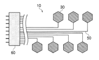
図2は本実施形態による液体吐出装置の要部構成を模式的に示した平面図である。図2に示すように、複数の圧力発生素子30は、ヘッド内におけるイジェクタ(図1の符号20)の配列形態に対応して配置されている。各圧力発生素子30は、それぞれ電気配線50によって回路制御素子60と接続されている。
FIG. 2 is a plan view schematically showing the main configuration of the liquid ejection apparatus according to the present embodiment. As shown in FIG. 2, the plurality of
図3は本実施形態に係る液体吐出装置の簡易回路図である。図3では図示の便宜上、圧力発生素子30の個数を減らして示した。図3に示すように、回路制御素子60内には複数のスイッチ62が含まれる。各スイッチ62はそれぞれ圧力発生素子30と接続されている。これらスイッチ62は、外部から与えられる制御信号(スイッチ選択信号)に応じて開閉制御される。回路制御素子60は、入力されるスイッチ選択信号にしたがい、対応するスイッチ62の開閉を行う制御回路が組み込まれている。このような回路制御素子60はASIC(Application Specific Integrated Circuit)で構成される。
FIG. 3 is a simplified circuit diagram of the liquid ejection apparatus according to the present embodiment. In FIG. 3, the number of the
インクジェットヘッド制御回路基板64は、ヘッド内の各圧力発生素子30を駆動して吐出を実行するための駆動制御手段(ヘッド駆動装置)として機能する。インクジェットヘッド制御回路基板64は、スイッチ62の開閉を制御するスイッチ選択信号の出力回路(図示せず)を含んでいる。スイッチ選択信号は、回路制御素子60内のスイッチ62のON/OFFを制御するための信号である。スイッチ選択信号にしたがって、スイッチ62の状態(ON/OFF)が切り替わる。
The inkjet head
また、インクジェットヘッド制御回路基板64は、圧力発生素子30に印加する電圧波形(駆動波形)のデータを記憶する波形メモリと、波形データに対応した駆動波形の信号(駆動信号)を出力する駆動電圧出力回路(図示せず)を含んでいる。詳細は後述するが、波形メモリには、記録解像度から規定される1画素(1打滴点)の記録を担う1印字周期の駆動波形のデータが格納される(図5、図7、図8、図10〜図14参照)。
The inkjet head
図3のように、インクジェットヘッド制御回路基板64から出力される駆動波形(電圧波形)は、各圧力発生素子30に繋がる複数のスイッチ62の一端に対して並列に供給される。回路制御素子60は、インクジェットヘッド制御回路基板64から供給されるスイッチ選択信号を使って、各圧力発生素子30に繋がるスイッチ62のON(閉)/OFF(開)を切り替える。スイッチ62のON/OFFによって、圧力発生素子30への駆動電圧の印加/非印加が制御される。
As shown in FIG. 3, the drive waveform (voltage waveform) output from the inkjet head
また、駆動波形の全体(以下、一記録周期の駆動波形の単位を「1駆動波形」と言う。)のうち、必要な部分だけを圧力発生素子30に印加するように、1駆動波形内でスイッチ62のON/OFFを切り換えることが可能である。1駆動波形内でスイッチをON/OFFする制御信号のことを「ラッチ信号」と呼ぶ。ラッチ信号はスイッチ選択信号に含まれている。
Further, in the entire drive waveform (hereinafter, the unit of the drive waveform in one recording period is referred to as “one drive waveform”), only a necessary portion is applied to the
(技術課題の整理)
図4は回路制御素子60が故障した場合の説明図である。図4のように、回路制御素子60内に故障したスイッチ62Bがあると、このスイッチ62Bに繋がる圧力発生素子30Bは、吐出を望まない場合でも動作し続けてしまう。
(Organization of technical issues)
FIG. 4 is an explanatory diagram when the
このように、インクジェットヘッド制御回路基板64から与えられるスイッチ選択信号によらず、ある特定のスイッチ62Bが閉じたままになってしまう場合がある。そうなると、そのスイッチ62Bに繋がる圧力発生素子30Bに対して駆動波形の全体が常に印加されてしまうので、用紙上に望ましくない画像ができてしまう。
Thus, a specific switch 62B may remain closed regardless of the switch selection signal given from the inkjet head
かかる課題を次の手段により解決する。 This problem is solved by the following means.
<第1実施例l;波形例1>
図5は第1実施例に係る駆動波形の例である。この駆動波形は、記録媒体上における1画素のドット記録を担う一記録周期の波形である。なお、「一記録周期」という用語は、当該分野において「一印字周期」、「一印刷周期」と呼ばれる場合がある。
<First embodiment l; waveform example 1>
FIG. 5 is an example of drive waveforms according to the first embodiment. This driving waveform is a waveform of one recording period that is responsible for dot recording of one pixel on the recording medium. Note that the term “one recording cycle” may be referred to as “one printing cycle” or “one printing cycle” in this field.
図5に示すような駆動波形の波形データをインクジェットヘッド制御回路基板64上の波形メモリに記憶させる。図5において横軸は時間(単位[μs])、縦軸は電圧(単位[V])を示す。同図に示す駆動波形は、符号Aで示した波形部(時間0.0〜2.0[μs]の範囲、「波形部A」という。)と、これに続く符号Bで示した波形部(時間2.0〜10.0[μs]の範囲、「波形部B」という。)の2領域を含んで構成されている。波形部Aを「副波形」と呼び、波形部Bを「主波形」と呼ぶ。明細書中、「副波形A」、「主波形B」と表記する場合がある。主波形は吐出駆動用の波形部に相当する。副波形は主波形と組み合わされることで吐出を抑制する吐出抑制用の波形部に相当する。
The waveform data of the drive waveform as shown in FIG. 5 is stored in the waveform memory on the inkjet head
図5の波形部Aは、基準電位Vref(=15V)から電位Va(=2V)まで電位を下げる立ち下がりの波形要素a1と、波形要素a1に続いて電位Va(=2V)から基準電位Vref(=15V)まで電位を上昇させる立ち上がりの波形要素a2とを含んで構成される。 5 includes a falling waveform element a1 that lowers the potential from the reference potential Vref (= 15V) to the potential Va (= 2V), and the reference potential Vref from the potential Va (= 2V) following the waveform element a1. And a rising waveform element a2 that raises the potential to (= 15V).
波形部Bは、波形要素a2に続いて基準電位Vref(=15V)から電位Vb(=4V)まで電位を下げる立ち下がりの波形要素b1と、波形要素b1に続いて電位Vb(=4V)を保持する波形要素b2と、波形要素b2に続いて電位Vbから基準電位Vref(=15V)まで電位を上昇させる立ち上がりの波形要素b3と、波形要素b3に続いて基準電位Vref=15Vを保持する波形要素b4とを含んで構成される。 The waveform section B applies a falling waveform element b1 that lowers the potential from the reference potential Vref (= 15V) to the potential Vb (= 4V) following the waveform element a2, and a potential Vb (= 4V) following the waveform element b1. The waveform element b2 to be held, the rising waveform element b3 for increasing the potential from the potential Vb to the reference potential Vref (= 15V) following the waveform element b2, and the waveform for holding the reference potential Vref = 15V following the waveform element b3 Element b4.
波形要素b1、b2、b3からなるパルスは、いわゆる引き-押し(pull-push)型の波形である。すなわち、波形要素b1は、圧力室の体積(容積)を拡張させる方向に圧電素子(図1の圧力発生素子30)を変形させる「引き(pull)」動作の駆動を行う。波形要素b2は、波形要素b1の引き動作で圧力室を拡張させた状態を維持(保持)する。波形要素b3は、圧力室を収縮させる方向に圧電素子を変形させる「押し(push)」動作の駆動を行う。
The pulse composed of the waveform elements b1, b2, and b3 is a so-called pull-push type waveform. That is, the waveform element b1 drives a “pull” operation that deforms the piezoelectric element (the
図5における副波形の波形要素a1は「引き」動作、波形要素a2は「押し」動作に対応している。なお、本例の場合、インクジェットヘッド10の圧力系の固有周期(共振周期)Tcは4μsであり、各波形要素(a1、a2、b1、b2、b3、b4)の境界(始点、終点)に対応する時間([μs]を単位とする時間軸の値)は「0.0」、「0.5」、「2.0」、「2.5」、「4.0」、「4.5」、「32.1」である。
The waveform element a1 of the sub waveform in FIG. 5 corresponds to the “pull” operation, and the waveform element a2 corresponds to the “push” operation. In the case of this example, the natural period (resonance period) Tc of the pressure system of the
図中の黒三角印「▼」は、ラッチタイミングを表している。このラッチタイミングでスイッチ(図3の符号62)の開閉を制御し、圧力発生素子(図3の符号30)に対して電圧を印加するか、しないかを選択する。図5に示した2つの「▼」が示すラッチタイミングのうち、先行する波形部Aの手前のラッチタイミングを「ラッチ1」、後続に係る波形部Bの手前のラッチタイミングを「ラッチ2」と呼ぶ。
The black triangle mark “▼” in the figure represents the latch timing. The opening / closing of the switch (
副波形(波形部A)を圧力発生素子に印加するか否かは、副波形(波形部A)の前のラッチ1により、スイッチを開閉して選択する。主波形(波形部B)を圧力発生素子に印加するか否かは、主波形(波形部B)の前のラッチ2により、スイッチを開閉して選択する。
Whether or not to apply the sub waveform (waveform portion A) to the pressure generating element is selected by opening and closing the switch by the
印刷すべき画像ファイル(PDF、TIFFなど)にRIP(Raster Image Processor)などの画像処理をかけることで、インクジェットヘッド10に複数個存在するノズルのうち、どのノズルからどのタイミングで液滴を吐出するかが決定される。
By applying image processing such as RIP (Raster Image Processor) to an image file (PDF, TIFF, etc.) to be printed, droplets are ejected from which nozzle at which timing among a plurality of nozzles existing in the
吐出させたいノズルの場合、ラッチ1で副波形をOFFにし、ラッチ2で主波形をONにする。吐出させたくないノズルの場合、ラッチ1で副波形をOFFにし、ラッチ2で主波形をOFFにする。回路制御素子60に故障がなければ、上記の制御によって正常に吐出の制御が行われる。
In the case of a nozzle to be ejected, the sub waveform is turned off by
何らかの原因で回路制御素子60内の一部のスイッチ62Bが故障している場合(図4参照)、ラッチ1、ラッチ2によるスイッチ62Bの開閉を制御できず、この制御不能なスイッチ62Bに繋がる圧力発生素子30Bに副波形も主波形もともに印加される。
When a part of the switches 62B in the
しかしながら、図5に示した駆動波形は、副波形と主波形が連続して圧力発生素子に印加されると液滴が吐出しないものとなっている。 However, the drive waveform shown in FIG. 5 is such that when the sub-waveform and the main waveform are applied to the pressure generating element in succession, droplets are not ejected.
これは、副波形によって作られる圧力波が、主波形が作る圧力波の少なくとも一部をキャンセルするように、副波形を設計しているからである。図5の波形で具体的に説明すると、副波形の立ち下げ部分(波形要素a1)によって作られる圧力波が、主波形の立ち下げ部分(波形要素b1)による圧力波をキャンセルする。この効果により、副波形と主波形が連続して圧力発生素子に印加されると液滴は吐出しない。 This is because the sub waveform is designed so that the pressure wave generated by the sub waveform cancels at least a part of the pressure wave generated by the main waveform. More specifically, referring to the waveform of FIG. 5, the pressure wave generated by the falling portion (waveform element a1) of the sub-waveform cancels the pressure wave generated by the falling portion (waveform element b1) of the main waveform. Due to this effect, when the sub waveform and the main waveform are continuously applied to the pressure generating element, the droplet is not ejected.
このように圧力波をキャンセルさせるためには、圧力室系の固有周期(「ヘッド共振周期」と呼ばれる場合もある。)を考慮して駆動波形を設計することが効果的である。圧力室系の固有周期(ヘルムホルツ固有振動周期)Tcは、インク流路系、インク(音響要素)、圧電素子の寸法、材料、物性値等から定まる振動系全体の固有周期である。固有周期Tcは、ヘッドの設計値(使用するインクの物性値を含む)から音響回路を計算することによって求めることができる。また、ヘッド設計値から推定する方法に限らず、実験によってTcを測定する方法もある。 In order to cancel the pressure wave in this way, it is effective to design the drive waveform in consideration of the natural period of the pressure chamber system (sometimes referred to as “head resonance period”). The natural period (Helmholtz natural vibration period) Tc of the pressure chamber system is a natural period of the entire vibration system determined from the ink flow path system, ink (acoustic element), dimensions, materials, physical property values, and the like of the piezoelectric element. The natural period Tc can be obtained by calculating the acoustic circuit from the design value of the head (including the physical property value of the ink to be used). In addition to the method of estimating from the head design value, there is also a method of measuring Tc by experiment.
例えば、単純な矩形波をつかって液滴の吐出状況を調べる実験を行う。矩形波のパルス幅を徐々に変化させて滴速と滴量を調べると、パルス幅の変化に対して、滴速度、滴量はともに、山なりに変化し、それぞれ増加から減少に転じるピークが現れる。滴速度がピーク(極大値)となるパルス幅と、滴量がピークとなるパルス幅とは必ずしも一致せず、両者に若干のずれが生じうるが、これらの測定結果からピーク位置の約2倍がTcとして計算される。 For example, an experiment is conducted to examine the discharge state of droplets using a simple rectangular wave. When the drop speed and drop volume are examined by gradually changing the pulse width of the rectangular wave, both the drop speed and drop volume change in a mountain with respect to the change in the pulse width, and there are peaks that increase and decrease respectively. appear. The pulse width at which the drop velocity reaches a peak (maximum value) and the pulse width at which the drop amount reaches a peak do not necessarily coincide with each other, and a slight deviation may occur between them. Is calculated as Tc.
本実施例のインクジェットヘッド10における圧力室系の固有周期Tcは4μsとしている。この場合、半固有周期(Tc/2)は2μsである。図5に示す駆動波形は、主波形に先行する副波形を印加することによって、主波形印加時の吐出効率を低下させる観点から、副波形の立ち下げ部分(波形要素a1)と、主波形の立ち下げ部分(波形要素b1)とを約2μs(半固有周期)だけ離して波形が設計されている。
The natural period Tc of the pressure chamber system in the
これにより、波形要素a1で発生する圧力波と波形要素b1で発生する圧力波とが打ち消し合い、圧力波を効果的にキャンセルさせることができる。 Thereby, the pressure wave generated in the waveform element a1 and the pressure wave generated in the waveform element b1 cancel each other, and the pressure wave can be effectively canceled.
<主波形の好ましい条件について>
ピエゾジェット方式のインクジェットヘッドの場合、1ノズルの吐出機構(イジェクタ20)は、ノズル孔(吐出口)に連通する圧力室に圧電素子が設けられ、この圧電素子を駆動して圧力室内の液に圧力変動を与え、ノズル孔から液滴の吐出を行う仕組みとなっている。図5に示す主波形は、基準電位から電圧を下げると、圧力室が膨張するため、圧力は低下し、ノズル内のメニスカスは圧力室の方向(吐出方向と反対向きの方向)に引き込まれる。この「引き」波形要素b1の印加によりメニスカスの引き込み動作が開始された後、引き電圧を一定に維持すると(波形要素b2)、振動系の固有振動周期でメニスカスが振動する。このメニスカス振動によって丁度吐出方向の速度が最大となるときに、圧力室を収縮させれば(波形要素b3)、最も加速されるところで、液滴を吐出することができる。このようなメニスカスの動きと、駆動波形による引き押しのサイクルを合わせることで効率的な吐出が可能である。
<Preferred conditions for main waveform>
In the case of a piezo jet type ink jet head, a one-nozzle ejection mechanism (ejector 20) is provided with a piezoelectric element in a pressure chamber communicating with a nozzle hole (ejection port). It is a mechanism for applying pressure fluctuations and discharging droplets from the nozzle holes. In the main waveform shown in FIG. 5, when the voltage is lowered from the reference potential, the pressure chamber expands, so the pressure decreases, and the meniscus in the nozzle is drawn in the direction of the pressure chamber (the direction opposite to the discharge direction). When the pulling operation is started by applying the “pulling” waveform element b1, and then the pulling voltage is kept constant (waveform element b2), the meniscus vibrates at the natural vibration period of the vibration system. If the pressure chamber is contracted (waveform element b3) when the velocity in the discharge direction is just maximized by this meniscus vibration, the droplet can be discharged at the most accelerated position. Efficient ejection is possible by combining the movement of the meniscus and the pulling and pushing cycle based on the drive waveform.
メニスカス振動の1周期が1共振周期Tcになるため、その約半分(Tc/2)でパルス幅を区切ると最も効率がよい。図5に例示した駆動波形10は、パルス幅をTc/2とほぼ一致させた例となっている。
Since one period of meniscus vibration is one resonance period Tc, it is most efficient to divide the pulse width by about half (Tc / 2). The
図5で説明したように、主波形の前に副波形を入れている場合、副波形部分で吐出しないように波形が設計される。図5で示した波形要素a1、a2から成る三角波形の場合、これだけが圧力発生素子30に印加されても、ノズルからインクが吐出されることはない。図5の副波形は、圧力室系の固有振動(共振)に適合したパルス幅となっておらず、吐出に必要な圧力波が効率的に発生しないためである。
As described with reference to FIG. 5, when a sub waveform is inserted before the main waveform, the waveform is designed so as not to discharge at the sub waveform portion. In the case of the triangular waveform composed of the waveform elements a1 and a2 shown in FIG. 5, even if only this is applied to the
主波形に先行する副波形は、当該副波形部分が圧力発生素子30に印加されても吐出が行われず、かつ、これに続く主波形の印加による吐出を抑制する(圧力波を打ち消す)ことが求められる。実験によれば、副波形(図5では三角波形)の最低電圧(Va)は、主波形(図5では矩形波)部分の最低電圧以下であることが好まく、副波形の最低電圧(Va)は、主波形の最低電圧よりも低い方がより好ましい。
The sub-waveform preceding the main waveform does not discharge even when the sub-waveform portion is applied to the
図5では、副波形の最低電圧(電位Va=2V)が、主波形の最低電圧(電位Vb=4V)よりも低く設定されている。本願の発明者らが実験やシミュレーションを実施したところ、Va≦Vbとなる条件を満たす構成の方が圧力波をキャンセルする(吐出効率を抑制する)効果が高いことが明らかになったためである。 In FIG. 5, the minimum voltage (potential Va = 2V) of the sub waveform is set lower than the minimum voltage (potential Vb = 4V) of the main waveform. This is because the inventors of the present application conducted experiments and simulations and found that the configuration satisfying the condition of Va ≦ Vb has a higher effect of canceling the pressure wave (suppressing the discharge efficiency).
副波形の最低電圧(電位Va)の条件を変えて吐出状態を調べた結果、副波形の最低電圧(電位Va)を、主波形の電圧振幅(基準電位Vrefと、最低電位Vbとの電位差、図5の例において11V)から0%〜30%低めに設定することが望ましい。図5の例では、主波形の電圧振幅(11V)に対して18%低めの「2V」を副波形の最低電圧とした。 As a result of examining the discharge state by changing the condition of the minimum voltage (potential Va) of the sub waveform, the minimum voltage (potential Va) of the sub waveform is changed to the voltage amplitude of the main waveform (potential difference between the reference potential Vref and the minimum potential Vb, It is desirable to set 0% to 30% lower than 11V) in the example of FIG. In the example of FIG. 5, “2V”, which is 18% lower than the voltage amplitude (11V) of the main waveform, is set as the minimum voltage of the sub waveform.
本例では、電圧の立ち下げによって圧力室を膨張させ、電圧の立ち上げによって圧力室を収縮させる構成としたため、上記の関係となっているが、逆に、電圧の立ち上げによって圧力室を膨張させ、電圧の立ち下げによって圧力室を収縮させるような駆動方式を採用することも可能である。この場合、基準電位に対するパルス(波形部)の電位差を電圧振幅とすると、副波形の電圧振幅を主波形の電圧振幅以上とする構成が好ましい。 In this example, the pressure chamber is expanded by lowering the voltage, and the pressure chamber is contracted by rising the voltage. Therefore, the relationship is as described above. Conversely, the pressure chamber is expanded by rising the voltage. It is also possible to adopt a driving method in which the pressure chamber is contracted by a voltage drop. In this case, when the potential difference of the pulse (waveform portion) with respect to the reference potential is a voltage amplitude, a configuration in which the voltage amplitude of the sub waveform is equal to or larger than the voltage amplitude of the main waveform is preferable.
なお、図5のように、ラッチを入れてスイッチ62を開閉するには、通常、0.1〜1μs等の時間が必要である。この時間の長さは、駆動回路やASIC性能に依存する。スイッチ62の開閉動作を安定的に行う場合には、ラッチ(▼)の部分に平坦電圧部分を設けることが望ましい。図5に示した第1実施例では、スイッチ62の安定動作を確保する時間長さの平坦電圧部分を省略して記載している。このような平坦電圧部分は、動作の安定性を向上させる点で有益な構成であるが、発明の実施に際して不可欠な要素ではない。
As shown in FIG. 5, in order to open and close the
<圧力発生素子への印加波形と吐出状態の関係>
図6は、図5に例示した駆動波形を用いた場合における副波形、主波形の選択パターンと吐出状態(吐出する/しない)の関係をパターン分けして表にまとめたものである。図6に示すように、印刷すべき画像内容において、ノズルに対応する画像情報がない場合には、ラッチ1、2で副波形及び主波形をともにオフにする。これにより、当該ノズルから液滴が吐出しない状態となる。
<Relationship between waveform applied to pressure generating element and discharge state>
FIG. 6 is a table in which the relationship between the sub-waveform and main waveform selection patterns and the discharge state (discharge / non-discharge) when the drive waveform illustrated in FIG. 5 is used is divided into patterns. As shown in FIG. 6, when there is no image information corresponding to the nozzle in the image content to be printed, both the sub waveform and the main waveform are turned off by the
ノズルに対応する画像情報がある場合には、ラッチ1で副波形をオフ、ラッチ2で主波形をオンにする。回路制御素子60のスイッチ62が正常に機能している場合には、ラッチ1、2による制御が有効に働き、圧力発生素子30には主波形のみが印加される。副波形がオフされ、主波形のみが独立して印加されることにより、当該ノズルから液滴が吐出される。
When there is image information corresponding to the nozzle, the sub waveform is turned off by
上記のような吐出制御方法を採用した場合、回路制御素子(ASIC)60の故障等によって、常時オンとなったスイッチに繋がる圧力発生素子に対しては、ラッチ1、2によるスイッチの開閉制御が不能となる。このため、副波形及び主波形がともにオンとなって、駆動波形の全体が当該圧力発生素子に印加される。このとき、ノズルから液滴は吐出しない。
When the discharge control method as described above is adopted, the opening / closing control of the switch by the
<「不吐出」、「吐出しない」という用語の概念について>
本明細書内で使用する「不吐出」、「吐出しない」という用語は、装置の用途に応じて
次の3つのいずれかの状態を意味するものとして解釈する必要がある。
<About the concept of the terms “non-ejection” and “no ejection”>
The terms “non-ejection” and “non-ejection” used in this specification should be interpreted as meaning any one of the following three states depending on the application of the apparatus.
(1)液滴がノズルから離れない。 (1) The droplet does not leave the nozzle.
(2)液滴はノズルから離れるが、用紙などの記録媒体(ベース)には着弾しない。 (2) The droplets leave the nozzle but do not land on the recording medium (base) such as paper.
例えば、滴量が非常に小さく、ベースまで到達できずに、どこかへ飛んでいってしまう場合、或いは、ファンなどによって回収されてしまうような場合がこれに該当する。 For example, this is the case when the amount of droplets is very small and it cannot reach the base and flies away, or is collected by a fan or the like.
(3)液滴がベースに着弾はするが、記録ドットとして機能しない。例えば、次のような例を挙げることができる。 (3) Although the droplets land on the base, they do not function as recording dots. For example, the following examples can be given.
<例1>:ベースに着弾しても、人間の目には判別できないレベルの小さい滴である。吐出効率が悪く、着弾滴が「ドット」として視認できないほど小さい。 <Example 1>: A small drop with a level that cannot be discerned by human eyes even when it hits the base. The ejection efficiency is poor and the landing droplet is so small that it cannot be visually recognized as a “dot”.
<例2>:マテリアルデポジションに拡張した場合、例えば、銅配線のパターンを作ろうとしている場合に、液滴が小さすぎて、着弾液滴が繋がらずに配線として機能しない。 <Example 2>: When expanding to material deposition, for example, when trying to make a copper wiring pattern, the droplets are too small and the landing droplets are not connected and do not function as wiring.
上記のように、液滴吐出装置の用途によって「不吐出」或いは「吐出しない」という用語の意味(許容範囲)が若干異なる。 As described above, the meaning (allowable range) of the term “non-ejection” or “no ejection” differs slightly depending on the application of the droplet ejection device.
高精細画像をプリントするインクジェット印刷機の場合には、ベース(記録媒体)に液滴が着弾しないことが望まれるので、(1)か(2)の概念で解釈し、銅配線を形成する配線描画装置の場合で、導通/非導通が重視されるような場合には(3)を含む概念に拡げることができる。 In the case of an ink jet printer that prints high-definition images, it is desirable that droplets do not land on the base (recording medium), so the wiring that forms the copper wiring is interpreted based on the concept (1) or (2). In the case of a drawing apparatus, when conduction / non-conduction is important, the concept can be extended to (3).
<第2実施例;波形例2>
第1実施例の技術思想をより一般的に記述すると、同じ方向の電圧変化を(2n+1)×(Tc/2)だけ離せば、圧力波はキャンセルする(ただし、nは0以上の整数)。図5は、副波形の波形要素a1と、主波形の波形要素b1は、同じ形の電圧変化であり、n=0の場合に該当する。
<Second Embodiment; Waveform Example 2>
To describe the technical idea of the first embodiment more generally, if the voltage change in the same direction is separated by (2n + 1) × (Tc / 2), the pressure wave is canceled (where n is an integer of 0 or more). In FIG. 5, the waveform element a <b> 1 of the sub waveform and the waveform element b <b> 1 of the main waveform have the same voltage change and correspond to the case of n = 0.
図7は、第2実施例に係る駆動波形の例である。図7に示す駆動波形は、n=1の場合に相当する。図7中、図5の例と同一又は類似する要素には同一の符号を付し、その説明は省略する。図7の駆動波形は、副波形の立ち上げ(波形要素a2)の後に、基準電位を保持する波形要素a3がある。この波形要素a3に続いて主波形の立ち下げ(波形要素b1)が入る。 FIG. 7 is an example of drive waveforms according to the second embodiment. The drive waveform shown in FIG. 7 corresponds to the case where n = 1. 7, elements that are the same as or similar to those in the example of FIG. 5 are given the same reference numerals, and descriptions thereof are omitted. The drive waveform of FIG. 7 has a waveform element a3 that holds the reference potential after the start of the sub waveform (waveform element a2). Following this waveform element a3, the main waveform falls (waveform element b1).
各波形要素(a1、a2、a3、b1、b2、b3、b4)の境界(始点、終点)に対応する時間([μs]を単位とする時間軸の値)は「0.0」、「0.5」、「2.0」、「6.0」、「6.5」、「8.0」、「8.5」、「32.1」である。 The time corresponding to the boundary (start point, end point) of each waveform element (a1, a2, a3, b1, b2, b3, b4) (time axis value in [μs]) is “0.0”, “0.5”. , “2.0”, “6.0”, “6.5”, “8.0”, “8.5”, “32.1”.
図7において、副波形の立ち下げ(波形要素a1)と主波形の立ち下げ(波形要素b1)の間の時間間隔が6μs、すなわち、3×(Tc/2)だけ離れている。これにより、副波形(波形部A)の立ち下げ(波形要素a1)で発生する圧力波と主波形(波形部B)の立ち下げ(波形要素b1)で発生する圧力波とが打ち消し合う。 In FIG. 7, the time interval between the fall of the sub waveform (waveform element a1) and the fall of the main waveform (waveform element b1) is 6 μs, that is , 3 × (Tc / 2) apart. As a result, the pressure wave generated by the fall of the sub waveform (waveform portion A) (waveform element a1) and the pressure wave generated by the fall of the main waveform (waveform portion B) (waveform element b1) cancel each other.
図7に示す駆動波形における副波形、主波形の選択パターンと吐出状態(吐出する/しない)の関係のパターン分けは、図6と同様であるため、記載を省略する。 The pattern division of the relationship between the sub waveform and the main waveform selection pattern and the ejection state (ejection / non-ejection) in the drive waveform shown in FIG. 7 is the same as in FIG.
<第3実施例;波形例3>
第1実施例(図5)及び第2実施例(図7)では、主波形が1パルスのみの構成であったが、本発明はマルチパルスにも適用することができる。図8にその例を示す。図8は、第3実施例に係る駆動波形の例である。図8の例において、図5の例と同一又は類似する要素には同一の符号を付し、その説明は省略する。また、圧力室系の固有周期Tcは、4μsであるとする。
<Third Example; Waveform Example 3>
In the first embodiment (FIG. 5) and the second embodiment (FIG. 7), the main waveform has only one pulse. However, the present invention can also be applied to multipulses. An example is shown in FIG. FIG. 8 is an example of a drive waveform according to the third embodiment. In the example of FIG. 8, the same or similar elements as those in the example of FIG. Further, it is assumed that the natural period Tc of the pressure chamber system is 4 μs.
図8に示す駆動波形は、符号A、C、Eで示した各波形部がそれぞれ副波形に相当し、符号B、D、Fで示した各波形部がそれぞれ主波形に相当する。 In the drive waveform shown in FIG. 8, each waveform portion indicated by reference signs A, C, and E corresponds to a sub waveform, and each waveform portion indicated by reference signs B, D, and F corresponds to a main waveform.
副波形Aと主波形Bの関係は図5で説明した例と同様である。また、図8における副波形Cと主波形Dの関係、副波形Eと主波形Fの関係も、副波形Aと主波形Bの関係と同様である。すなわち、副波形Cの波形要素C1で発生する圧力波と主波形Dの波形要素d1で発生する圧力波が打ち消し合う。副波形Eの波形要素e1で発生する圧力波と主波形Fの波形要素f1で発生する圧力波が打ち消し合う。 The relationship between the sub waveform A and the main waveform B is the same as the example described in FIG. In addition, the relationship between the sub waveform C and the main waveform D and the relationship between the sub waveform E and the main waveform F in FIG. 8 are the same as the relationship between the sub waveform A and the main waveform B. That is, the pressure wave generated in the waveform element C1 of the sub-waveform C and the pressure wave generated in the waveform element d1 of the main waveform D cancel each other. The pressure wave generated in the waveform element e1 of the sub-waveform E and the pressure wave generated in the waveform element f1 of the main waveform F cancel each other.
波形要素C1、C2からなる副波形Cのパルスの手前にラッチのタイミング(「ラッチ3」という。)がある。波形要素d1、d2、d3、d4からなる主波形のパルスの手前にラッチのタイミング(「ラッチ4」という。)がある。波形要素e1、e2からなる副波形Eのパルスの手前にラッチのタイミング(「ラッチ5」という。)がある。波形要素f1、f2、f3、f4からなる主波形のパルスの手前にラッチのタイミング(「ラッチ6」という。)がある。このように、各パルスの前にラッチ1〜6があり、スイッチ62の開閉を制御する。
There is a latch timing (referred to as “
各波形要素(a1、a2、b1、b2、b3、b4、c1、c2、d1、d2、d3、d4、e1、e2、f1、f2、f3、f4)の境界(始点、終点)に対応する時間([μs]を単位とする時間軸の値)は「0.0」、「0.5」、「2.0」、「2.5」、「4.0」、「4.5」、「5.0」、「5.5」、「7.0」、「7.5」「9.0」、「9.5」、「10.0」、「10.5」、「12.0」、「12.5」、「14.0」、「14.5」「32.1」である。 Corresponds to the boundary (start point, end point) of each waveform element (a1, a2, b1, b2, b3, b4, c1, c2, d1, d2, d3, d4, e1, e2, f1, f2, f3, f4) Time (time axis value in [μs]) is “0.0”, “0.5”, “2.0”, “2.5”, “4.0”, “4.5”, “5.0”, “5.5”, “7.0” , “7.5”, “9.0”, “9.5”, “10.0”, “10.5”, “12.0”, “12.5”, “14.0”, “14.5”, “32.1”.
図8のようなマルチパルスを利用するメリットは、印加する主波形の組み合わせによって、吐出液滴の体積を変化させることができることである。例えば、主波形Bのみを印加すると小滴、主波形Bと主波形Dを印加すると中滴、主波形Bと主波形D及び主波形Fを印加すると大滴、という具合に滴サイズを変更することができる。 The advantage of using the multi-pulse as shown in FIG. 8 is that the volume of the ejected droplets can be changed by a combination of main waveforms to be applied. For example, the droplet size is changed such that a small droplet is applied when only the main waveform B is applied, a medium droplet is applied when the main waveform B and the main waveform D are applied, and a large droplet is applied when the main waveform B, the main waveform D and the main waveform F are applied. be able to.
図8の駆動波形を用いた場合における副波形、主波形の選択パターンと吐出状態(吐出する/しない)の関係をパターン分けして図9の表にまとめた。記録を行わない場合には、全てのラッチ1〜6でオフを指令し、副波形A、C、E、主波形B、D、Fを全てオフにする。これにより、ノズルから液滴は吐出されない。
The relationship between the sub-waveform and main waveform selection pattern and the discharge state (discharge / non-discharge) when the drive waveform of FIG. 8 is used is divided into patterns and summarized in the table of FIG. When recording is not performed, all the
小滴を吐出させるノズルに対しては、副波形A、C、Eをオフ、主波形Bをオン、他の主波形D、Fをオフにする。 For nozzles that eject droplets, the sub-waveforms A, C, and E are turned off, the main waveform B is turned on, and the other main waveforms D and F are turned off.
中滴を吐出させるノズルに対しては、副波形A、C、Eをオフ、主波形B、Dをオン、他の主波形Fをオフにする。これにより、当該ノズルの圧力発生素子には、主波形B、Dが連続的に印加され、2発の連射によって中滴のドットが記録される。 For nozzles that eject medium drops, the sub-waveforms A, C, and E are turned off, the main waveforms B and D are turned on, and the other main waveforms F are turned off. As a result, the main waveforms B and D are continuously applied to the pressure generating element of the nozzle, and a medium dot is recorded by two consecutive shots.
大滴を吐出させるノズルに対しては、副波形A、C、Eをオフ、主波形B、Dをオン、他の主波形Fをオンにする。これにより、当該ノズルの圧力発生素子には、主波形B、D、Fが連続的に印加され、3発の連射によって大滴のドットが記録される。 For nozzles that eject large droplets, the sub waveforms A, C, and E are turned off, the main waveforms B and D are turned on, and the other main waveforms F are turned on. As a result, the main waveforms B, D, and F are continuously applied to the pressure generating element of the nozzle, and large dots are recorded by three consecutive shots.
回路制御素子60内のスイッチが故障して常時オンの状態になると、ラッチ1〜6による制御が不能となり、駆動波形の全体(副波形A、C、E、主波形B、D、F)が圧力発生素子に印加される。この場合、図6で説明した例と同様に、ノズルから液は吐出されない。
When a switch in the
なお、図9では、駆動波形の前側から主波形を選択して、主波形Bのみで小滴、主波形B+Dで中滴、主波形B+D+Fで大滴としたが、滴サイズの変更に際して、パルスの選択方法はこれに限定されない。例えば、駆動波形の後ろ側から主波形を選択して、主波形Fのみで小滴、主波形D+Fで中滴、主波形B+D+Fで大滴とする構成も可能である。 In FIG. 9, the main waveform is selected from the front side of the drive waveform, the main waveform B alone is a small droplet, the main waveform B + D is a medium droplet, and the main waveform B + D + F is a large droplet. The selection method is not limited to this. For example, a configuration in which a main waveform is selected from the rear side of the drive waveform and a main waveform F alone is a small droplet, a main waveform D + F is a medium droplet, and a main waveform B + D + F is a large droplet is possible.
<第4実施例;波形例4>
第1実施例〜第3実施例で例示したように、主波形の前に副波形を入れている場合、副波形部分で吐出しないように構成する。図5、図7、図8で示した三角波形による副波形の場合、副波形単独で圧力発生素子30に印加されても、吐出することはない。これは、三角波のパルス幅と圧力室系の共振の周期との関係から、圧力波が効率的に発生しないためである。圧力波が効率的に発生しない波形として、三角波形以外の手段も可能である。
<Fourth Example; Waveform Example 4>
As illustrated in the first to third embodiments, when the sub waveform is inserted before the main waveform, the sub waveform is not discharged. In the case of the sub waveform with the triangular waveform shown in FIGS. 5, 7, and 8, even if the sub waveform alone is applied to the
図10は第4実施例に係る駆動波形の波形図である。図10の駆動波形は、副波形Aの立ち上げ部分で、電圧を段階的に(ステップ状に)上昇させる構成となっている。すなわち、図10の副波形Aは、立ち下げの波形要素a1、電圧保持の波形要素a12、立ち上げの波形要素a21、電圧保持の波形要素a22、立ち上げの波形要素a23、電圧保持の波形要素a24、立ち上げの波形要素a25、電圧保持の波形要素a3から構成されている。主波形Bの構成は図5の例と同様である。各波形要素(a1、a12、a21、a22、a23、a24、a25、a3、b1、b2、b3、b4)の境界(始点、終点)に対応する時間([μs]を単位とする時間軸の値)は「0.0」、「0.5」、「0.7」、「0.9」、「1.1」、「1.3」、「1.7」、「2.0」、「2.5」、「4.0」、「4.5」、「32.1」である。 FIG. 10 is a waveform diagram of drive waveforms according to the fourth embodiment. The drive waveform in FIG. 10 is configured to increase the voltage stepwise (stepwise) at the rising portion of the sub-waveform A. That is, the sub-waveform A in FIG. 10 includes a falling waveform element a1, a voltage holding waveform element a12, a rising waveform element a21, a voltage holding waveform element a22, a rising waveform element a23, and a voltage holding waveform element. a24, a rising waveform element a25, and a voltage holding waveform element a3. The configuration of the main waveform B is the same as in the example of FIG. On the time axis in units of [μs] corresponding to the boundaries (start point, end point) of each waveform element (a1, a12, a21, a22, a23, a24, a25, a3, b1, b2, b3, b4) Value) is "0.0", "0.5", "0.7", "0.9", "1.1", "1.3", "1.7", "2.0", "2.5", "4.0", "4.5", "32.1" It is.
電圧の立ち上げ部分(波形要素a21〜a25)において、段階的に電圧を上げていく波形を採用することにより、吐出効率は低下する。このため、副波形Aが単独で印加されても吐出しない。 By adopting a waveform in which the voltage is increased step by step in the voltage rising portion (waveform elements a21 to a25), the discharge efficiency is lowered. For this reason, even if the sub waveform A is applied alone, it does not discharge.
また、副波形Aの立ち下げ部分(波形要素a1)と主波形Bの立ち下げ部分(波形要素b1)との間の時間間隔を半固有周期(Tc/2)の奇数倍とする構成により、副波形Aと主波形Bを組み合わせて印加した場合に圧力波をキャンセルする効果が得られる。図10の例では、圧力室系の固有周期Tc=4μsのヘッドに対して、波形要素a1と波形要素b1が2μsだけ離れている。よって、図10の駆動波形全体が圧力発生素子に印加された場合、液滴は吐出しない。 Further, the time interval between the falling portion (waveform element a1) of the sub-waveform A and the falling portion (waveform element b1) of the main waveform B is set to an odd multiple of the semi-natural period (Tc / 2). When the sub-waveform A and the main waveform B are applied in combination, the effect of canceling the pressure wave is obtained. In the example of FIG. 10, the waveform element a1 and the waveform element b1 are separated by 2 μs from the head having the natural period Tc = 4 μs of the pressure chamber system. Therefore, when the entire drive waveform of FIG. 10 is applied to the pressure generating element, no droplet is ejected.
図10に示す駆動波形における副波形、主波形の選択パターンと吐出状態(吐出する/しない)の関係のパターン分けは、図6と同様であるため、記載を省略する。 The pattern classification of the relationship between the sub-waveform and main waveform selection patterns in the drive waveform shown in FIG. 10 and the discharge state (discharge / non-discharge) is the same as in FIG.
<第5実施例;波形例5>
図11は第5実施例に係る駆動波形の波形図である。図11において、図10の構成例と同一の要素には同一の符号を付した。図11の駆動波形は、副波形Aの立ち上げ部分がS字カーブに沿う構成となっている。このような構成を採用しても、圧力波の発生効率を下げることができる。
<Fifth embodiment; waveform example 5>
FIG. 11 is a waveform diagram of drive waveforms according to the fifth embodiment. In FIG. 11, the same elements as those in the configuration example of FIG. The drive waveform of FIG. 11 has a configuration in which the rising portion of the sub-waveform A follows an S-shaped curve. Even if such a configuration is adopted, the generation efficiency of the pressure wave can be lowered.
このため、副波形Aが単独で印加されても吐出しない。また、副波形Aの立ち下げ部分(波形要素a1)と主波形Bの立ち下げ部分(波形要素b1)との間の時間間隔を半固有周期(Tc/2)の奇数倍とする構成により、副波形Aと主波形Bを組み合わせて印加した場合に圧力波をキャンセルする効果が得られる。図11の例では、圧力室系の固有周期Tc=4μsのヘッドに対して、波形要素a1と波形要素b1が2μsだけ離れている。よって、図11の駆動波形全体が圧力発生素子に印加された場合、液滴は吐出しない。 For this reason, even if the sub waveform A is applied alone, it does not discharge. Further, the time interval between the falling portion (waveform element a1) of the sub-waveform A and the falling portion (waveform element b1) of the main waveform B is set to an odd multiple of the semi-natural period (Tc / 2). When the sub-waveform A and the main waveform B are applied in combination, the effect of canceling the pressure wave is obtained. In the example of FIG. 11, the waveform element a1 and the waveform element b1 are separated by 2 μs with respect to the head having the natural period Tc = 4 μs of the pressure chamber system. Therefore, when the entire drive waveform of FIG. 11 is applied to the pressure generating element, no droplet is ejected.
<第6実施例;波形例6>
図12は第6実施例に係る駆動波形の波形図である。図12の例では、副波形Aの電圧立ち上げ部分(波形要素a2)で、主波形Bの電圧立ち上げ部分(波形要素b3)の圧力波をキャンセルするように波形が設計されている。なお、ヘッドの圧力室系の固有周期Tcは4μsとしている。
<Sixth embodiment; waveform example 6>
FIG. 12 is a waveform diagram of drive waveforms according to the sixth embodiment. In the example of FIG. 12, the waveform is designed so as to cancel the pressure wave of the voltage rising portion (waveform element b3) of the main waveform B at the voltage rising portion (waveform element a2) of the sub-waveform A. The natural period Tc of the pressure chamber system of the head is 4 μs.
図12の副波形Aは、波形要素a1と波形要素a2からなる三角波形で構成され、これに続く主波形Bは、波形要素b1、b2、b3、b4の矩形波形(台形波形)で構成される。図12において各波形要素(a1、a2、b1、b2、b3、b4)の境界(始点、終点)に対応する時間([μs]を単位とする時間軸の値)は「0.0」、「1.5」、「2.0」、「2.5」、「3.5」、「4.0」、「32.1」である。 The sub-waveform A in FIG. 12 is composed of a triangular waveform composed of a waveform element a1 and a waveform element a2, and the main waveform B following this is composed of rectangular waveforms (trapezoidal waveforms) of waveform elements b1, b2, b3, and b4. The In FIG. 12, the time corresponding to the boundary (start point, end point) of each waveform element (a1, a2, b1, b2, b3, b4) (time axis value in [μs]) is “0.0”, “1.5”. ”,“ 2.0 ”,“ 2.5 ”,“ 3.5 ”,“ 4.0 ”,“ 32.1 ”.
また、副波形Aの立ち上げ部分(波形要素a2)と主波形Bの立ち上げ部分(波形要素b3)との間の時間間隔を半固有周期(Tc/2)の奇数倍とする構成により、副波形Aと主波形Bを組み合わせて印加した場合に圧力波をキャンセルする効果が得られる。図12の例では、圧力室系の固有周期Tc=4μsのヘッドに対して、波形要素a2と波形要素b3が2μsだけ離れている。よって、図12の駆動波形全体が圧力発生素子に印加された場合、液滴は吐出しない。 Further, the time interval between the rising portion of the sub-waveform A (waveform element a2) and the rising portion of the main waveform B (waveform element b3) is an odd multiple of the semi-natural period (Tc / 2), When the sub-waveform A and the main waveform B are applied in combination, the effect of canceling the pressure wave is obtained. In the example of FIG. 12, the waveform element a2 and the waveform element b3 are separated from each other by 2 μs with respect to the head having the natural period Tc = 4 μs of the pressure chamber system. Therefore, when the entire drive waveform of FIG. 12 is applied to the pressure generating element, no droplet is ejected.
図12に示す駆動波形における副波形、主波形の選択パターンと吐出状態(吐出する/しない)の関係のパターン分けは、図6と同様であるため、記載を省略する。 The pattern division of the relationship between the sub-waveform and main waveform selection patterns in the drive waveform shown in FIG. 12 and the discharge state (discharge / non-discharge) is the same as in FIG.
<第7実施例;波形例7>
図13は第7実施例に係る駆動波形の波形図である。図13に示す駆動波形は、副波形Aのパルスを主波形Bのパルスと反対方向の電圧変化とし、主波形Bに対して副波形Aを固有周期Tc分手前に置く構成となっている。なお、固有周期Tc=4μsとしている。
<Seventh embodiment; waveform example 7>
FIG. 13 is a waveform diagram of drive waveforms according to the seventh embodiment. The drive waveform shown in FIG. 13 has a configuration in which the pulse of the sub waveform A is changed in voltage in the opposite direction to the pulse of the main waveform B, and the sub waveform A is placed in front of the main waveform B by the natural period Tc. Note that the natural period Tc = 4 μs.
図13における副波形Aは、基準電位Vref(=15V)から電位Va(=28V)まで電位を上昇させる立ち上げの波形要素a5と、波形要素a5に続いて電位Va(=28V)を保持する波形要素a6と、波形要素a6に続いて電位Va(=28V)から基準電位Vref(=15V)まで電位を下げる立ち下げの波形要素a7と、波形要素a7に続いて基準電位Vref(=15V)を保持する波形要素a8とを含んで構成される。 The sub-waveform A in FIG. 13 holds the rising waveform element a5 that raises the potential from the reference potential Vref (= 15V) to the potential Va (= 28V), and the potential Va (= 28V) following the waveform element a5. The waveform element a6, the falling waveform element a7 that lowers the potential from the potential Va (= 28V) to the reference potential Vref (= 15V) following the waveform element a6, and the reference potential Vref (= 15V) following the waveform element a7 And a waveform element a8 that holds the waveform.
主波形Bは、波形要素a8に続いて基準電位Vref(=15V)から電位Vb(=2V)まで電位を下げる立ち下がりの波形要素b1と、波形要素b1に続いて電位Vb(=2V)を保持する波形要素b2と、波形要素b2に続いて電位Vbから基準電位Vref(=15V)まで電位を上昇させる立ち上がりの波形要素b3と、波形要素b3に続いて基準電位Vre(f=15V)を保持する波形要素b4とを含んで構成される。図13の各波形要素(a5、a6、a7、a8、b1、b2、b3、b4)の境界(始点、終点)に対応する時間([μs]を単位とする時間軸の値)は「0.0」、「0.5」、「2.0」、「2.5」、「4.0」、「4.5」、「6.0」、「6.5」、「32.1」である。 The main waveform B is the fall of the waveform element b1 lowering the potential from subsequently the reference potential Vref to the waveform element a 8 (= 15V) to the potential Vb (= 2V), following the waveform element b1 potential Vb (= 2V) , The waveform element b2 that rises from the potential Vb to the reference potential Vref (= 15V) following the waveform element b2, and the reference potential Vre (f = 15V) following the waveform element b3. And a waveform element b4 that holds The time corresponding to the boundary (start point, end point) of each waveform element (a5, a6, a7, a8, b1, b2, b3, b4) in FIG. 13 (time axis value in units of [μs]) is “0.0. ”,“ 0.5 ”,“ 2.0 ”,“ 2.5 ”,“ 4.0 ”,“ 4.5 ”,“ 6.0 ”,“ 6.5 ”,“ 32.1 ”.
このような駆動波形によれば、主波形Bが作る圧力波を副波形Aが作る圧力波でキャンセルさせることができる。 According to such a drive waveform, the pressure wave produced by the main waveform B can be canceled by the pressure wave produced by the sub waveform A.
副波形Aの立ち上げ部分(波形要素a5)と主波形Bの立ち下げ部分(波形要素b1)の間の時間間隔は、固有周期Tcだけ離れている。また、副波形Aの立ち下げ部分(波形要素a7)と主波形の立ち上げ部分(波形要素b3)の間の時間間隔は固有周期Tcだけ離れている。このように副波形Aの立ち上げ/立ち下げの波形要素と、主波形Bの立ち下げ/立ち上げの波形要素が印加される時間がTcだけ離れていることから、副波形Aが作る圧力波が、主波形Bの作る圧力波を打ち消す。これにより、副波形Aと主波形Bが連続して圧力発生素子に印加されると(図13の駆動波形の全体が印加されると)、ノズルから液は吐出しない。 The time interval between the rising portion (waveform element a5) of the sub-waveform A and the falling portion (waveform element b1) of the main waveform B is separated by the natural period Tc. Further, the time interval between the falling portion of the sub-waveform A (waveform element a7) and the rising portion of the main waveform (waveform element b3) is separated by the natural period Tc. As described above, since the time for applying the rising / falling waveform element of the sub-waveform A and the falling / starting-up waveform element of the main waveform B are separated by Tc, the pressure wave generated by the sub-waveform A However, the pressure wave created by the main waveform B is canceled. Thus, when the sub waveform A and the main waveform B are continuously applied to the pressure generating element (when the entire driving waveform of FIG. 13 is applied), the liquid is not discharged from the nozzle.
また、図示の副波形Aのように、押し波形(波形要素a5)だけで吐出させようとすると、非効率であるため、この副波形Aを印加しただけでは吐出しない。 Further, as shown in the illustrated sub-waveform A, if it is attempted to eject only by the push waveform (waveform element a5), it is inefficient, so that the sub-waveform A is not ejected only by application.
第7実施例の技術思想を一般化すると、副波形の電圧立ち上げ部分と主波形の電圧立ち下げ部分、或いは、副波形の電圧立ち下げ部分と主波形の電圧立ち上げ部分、のように、互いに反対方向の電圧変化の波形要素をTcの整数倍だけ、時間を離す。つまり、逆方向の電圧変化をもたらす波形要素が(n+1)×Tcだけ時間的に離れて印加される波形とする(ただし、nは0以上の整数)。このような構成を採用することにより、これら波形要素の印加によって生じる圧力波をキャンセルする効果が得られる。 Generalizing the technical idea of the seventh embodiment, the voltage rising part of the sub waveform and the voltage falling part of the main waveform, or the voltage falling part of the sub waveform and the voltage rising part of the main waveform, The waveform elements of voltage changes in opposite directions are separated by an integer multiple of Tc. That is, a waveform element that causes a voltage change in the reverse direction is applied with a time interval of (n + 1) × Tc (where n is an integer of 0 or more). By adopting such a configuration, an effect of canceling the pressure wave generated by the application of these waveform elements can be obtained.
図13の例では、副波形Aの電圧振幅(|Va−Vref|=13V)と、主波形Bの電圧振幅(|Vref−Vb|=13V)が等しい場合を例示しているが、副波形Aの電圧振幅と主波形Bの電圧振幅は異なる値であってもよい。 In the example of FIG. 13, the voltage amplitude of the sub waveform A (| Va−Vref | = 13 V) and the voltage amplitude of the main waveform B (| Vref−Vb | = 13 V) are illustrated. The voltage amplitude of A and the voltage amplitude of the main waveform B may be different values.
図5で説明したように、主波形に先行する副波形は、当該副波形部分が圧力発生素子30に印加されても吐出が行われず、かつ、これに続く主波形の印加による吐出を効果的に抑制する(圧力波を打ち消す)ことが求められる。具体的な波形は種々の設計が可能であるが、副波形Aの電圧振幅を主波形Bの電圧振幅以上とする構成が好ましい。
As described with reference to FIG. 5, the sub-waveform preceding the main waveform does not discharge even when the sub-waveform portion is applied to the
<第8実施例;波形例8>
図14は第8実施例に係る駆動波形の波形図である。図14に示す駆動波形は、主波形Bが印加される前に、副波形Aが存在する。この副波形Aは、基準電位Vref(=15V)から電位Va1(=28V)に電圧を上昇させる立ち上げの波形要素a5と、波形要素a5に続いて電位Va(=28V)を保持する波形要素a6と、波形要素a6に続いて電位Va1から電位Va2(=4V)まで電圧を下げる立ち下げの波形要素a7と、波形要素a7に続いて電位Va2から基準電位Vrefまで電圧を上昇させる波形要素a8と、基準電位Vref(=15V)を保持する波形要素a9とを含んで構成される。
<Eighth Example; Waveform Example 8>
FIG. 14 is a waveform diagram of drive waveforms according to the eighth embodiment. The drive waveform shown in FIG. 14 has a sub waveform A before the main waveform B is applied. The sub-waveform A includes a rising waveform element a5 that raises the voltage from the reference potential Vref (= 15V) to the potential Va1 (= 28V), and a waveform element that holds the potential Va (= 28V) following the waveform element a5. a6, a falling waveform element a7 that lowers the voltage from the potential Va1 to the potential Va2 (= 4V) following the waveform element a6, and a waveform element a8 that increases the voltage from the potential Va2 to the reference potential Vref following the waveform element a7. And a waveform element a9 that holds the reference potential Vref (= 15 V).
主波形Bは、波形要素a9に続いて基準電位Vref(=15V)から電位Vb(=2V)まで電位を下げる立ち下がりの波形要素b1と、波形要素b1に続いて電位Vb(=2V)を保持する波形要素b2と、波形要素b2に続いて電位Vbから基準電位Vref(=15V)まで電位を上昇させる立ち上がりの波形要素b3と、波形要素b3に続いて基準電位Vref=15Vを保持する波形要素b4とを含んで構成される。図14の各波形要素(a5、a6、a7、a8、a9、b1、b2、b3、b4)の境界(始点、終点)に対応する時間([μs]を単位とする時間軸の値)は「0.0」、「0.5」、「1.5」、「2.0」、「2.5」、「4.0」、「4.5」、「6.0」、「6.5」、「32.1」である。 The main waveform B is the fall of the waveform element b1 lowering the potential from subsequently the reference potential Vref to the waveform element a 9 (= 15V) to the potential Vb (= 2V), following the waveform element b1 potential Vb (= 2V) Is held, the rising waveform element b3 for raising the potential from the potential Vb to the reference potential Vref (= 15V) following the waveform element b2, and the reference potential Vref = 15V following the waveform element b3. And a waveform element b4. The time corresponding to the boundary (start point, end point) of each waveform element (a5, a6, a7, a8, a9, b1, b2, b3, b4) in FIG. 14 (time axis value in [μs] as a unit) is “0.0”, “0.5”, “1.5”, “2.0”, “2.5”, “4.0”, “4.5”, “6.0”, “6.5”, “32.1”.
このような駆動波形を圧力発生素子に印加すると、副波形Aの引き部分(28Vから4Vへ電圧を急激に低下させる波形要素a7によって圧力室が拡張される駆動部分)によって、メニスカスがノズル内部に一気に引き込まれ、メニスカスが破壊される。その結果、ノズル内に気泡が巻き込まれる。このため、副波形Aに続いて主波形Bが印加されても、ノズルから液滴を吐出することができない。 When such a drive waveform is applied to the pressure generating element, the meniscus is brought into the nozzle by the pulling portion of the sub-waveform A (the drive portion in which the pressure chamber is expanded by the waveform element a7 that rapidly reduces the voltage from 28 V to 4 V). At a stretch, the meniscus is destroyed. As a result, bubbles are caught in the nozzle. For this reason, even if the main waveform B is applied subsequent to the sub-waveform A, droplets cannot be ejected from the nozzle.
図15は、図14に示す駆動波形における副波形、主波形の選択パターンと吐出状態(吐出する/しない)の関係をパターン分けして表にまとめたものである。図15に示すように、記録を行わない場合(画像なしの場合)には、ラッチ1、2でオフを指令し、副波形A、主波形Bをともにオフにする。これにより、ノズルから液滴は吐出されない状態となる。
FIG. 15 is a table in which the relationship between the sub-waveform and main waveform selection patterns in the drive waveform shown in FIG. 14 and the discharge state (discharge / non-discharge) is divided into patterns. As shown in FIG. 15, when recording is not performed (when there is no image), the
記録を行うノズルに対しては、ラッチ1で副波形Aをオフし、ラッチ2で主波形Bをオンにする。これにより、主波形Bのみが印加され、ノズルから液滴が吐出される。
For the nozzle for recording, the sub waveform A is turned off by the
回路制御素子60内のスイッチが故障して常時オンの状態になると、ラッチ1、2による制御が不能となり、駆動波形の全体(副波形A、主波形B)が圧力発生素子に印加される。この場合、先行する副波形Aの印加によりノズル内部に気泡が巻き込まれた後に、後続の主波形Bが印加されるため、ノズルから液滴は吐出されない。
When a switch in the
<実施例の組み合わせについて>
第1実施例〜第8実施例で説明した技術思想を必要に応じて適宜組み合わせる構成も可能である。例えば、図7、図8、図12で説明した駆動波形の副波形の電圧立ち上がり部分に図10や図11のような構成を適用することができる。また、図12〜図14で説明した副波形と主波形の組み合わせを、図8のように複数組み繋ぎ合わせる構成も可能である。
<Combination of Examples>
A configuration in which the technical ideas described in the first to eighth embodiments are appropriately combined as necessary is also possible. For example, the configuration as shown in FIG. 10 or FIG. 11 can be applied to the voltage rising portion of the sub waveform of the drive waveform described in FIG. 7, FIG. 8, and FIG. Further, a configuration in which a plurality of combinations of the sub waveform and the main waveform described in FIGS. 12 to 14 are connected as shown in FIG. 8 is also possible.
<インクジェット記録装置の構成例>
図16は、本発明の実施形態に係る液体吐出ヘッドの駆動装置が適用されたインクジェット記録装置の構成例を示すブロック図である。インクジェットヘッド10は、複数個のヘッドモジュール12a、12bを組み合わせて構成される。ここでは、説明を簡単にするために、2つのヘッドモジュール12a、12bを図示したが、1つのプリントヘッドを構成するヘッドモジュールの数は特に限定されない。
<Configuration example of inkjet recording apparatus>
FIG. 16 is a block diagram illustrating a configuration example of an ink jet recording apparatus to which the liquid ejection head driving device according to the embodiment of the present invention is applied. The
ヘッドモジュール12a、12bのインク吐出面には、複数のノズル(図1の符号22参照)が高密度で二次元配置されている。また、ヘッドモジュール12a、12bには、各ノズルに対応した圧力発生素子(図1の符号30)が設けられている。図2で説明した回路制御素子60はヘッドモジュール12a、12bに搭載されている。
A plurality of nozzles (see
被描画媒体としての用紙(図示せず)の幅方向に対して、複数個のヘッドモジュール12a、12bを繋ぎ合わせることにより、紙幅方向の全記録可能範囲(描画可能幅の全域)について所定の記録解像度(例えば、1200dpi)で描画可能なノズル列を有する長尺のラインヘッド(シングルパス印字が可能なページワイドヘッド)が構成される。
By connecting a plurality of
インクジェットヘッド10に接続されているヘッド制御部70(「液体吐出ヘッドの駆動装置」に相当)は、ヘッドモジュール12a、12bの各ノズルに対応する圧電素子の駆動を制御し、ノズルからのインク吐出動作(吐出の有無、液滴吐出量)を制御するための制御手段として機能する。
A head control unit 70 (corresponding to a “liquid ejection head driving device”) connected to the
ヘッド制御部70は、画像データメモリ72、画像データ転送制御回路74、吐出タイミング制御部75、波形メモリ76、駆動電圧制御回路78、D/A変換器79a、79bを含んで構成される。なお、本例では、画像データ転送制御回路74が「ラッチ信号送信回路」を含んでおり、画像データ転送制御回路74から各ヘッドモジュール12a、12bに適宜のタイミングでデータラッチ信号が出力される。
The
画像データメモリ72には、印刷用イメージデータ(ドットデータ)に展開された画像データが記憶される。波形メモリ76には、圧電素子を作動させるための駆動信号の電圧波形(駆動波形)を示すデジタルデータが記憶される。例えば、図5、図7、図8、図10〜図14で説明した駆動波形のデータ及びパルスの区切りを示すデータなどが波形メモリ76に格納される。画像データメモリ72に入力される画像データや、波形メモリ76に入力される波形データは、上位データ制御部80(「上位制御装置」に相当)にて管理される。上位データ制御部80は、例えば、パソコンやホストコンピュータで構成することができる。ヘッド制御部70は、上位データ制御部80からデータを受け取るためのデータ通信手段として、USB(Universal SerialBus)その他の通信インターフェースを備えている。
The
図16では、説明を簡単にするために、1つのインクジェットヘッド10(1色分)のみを示しているが、複数色のインクの各色に対応した複数本の(色別の)プリントヘッドを備えるインクジェット記録装置の場合、各色のインクジェットヘッド10について個別に(ヘッド単位で)ヘッド制御部70が設けられる。例えば、シアン(C)、マゼンタ(M)、イエロー(Y)、黒(K)の4色に対応した色別のプリントヘッドを備える構成では、CMYK各色のプリントヘッドにそれぞれヘッド制御部70が設けられ、これら各色のヘッド制御部を1つの上位データ制御部80が管理する構成が採用される。
In FIG. 16, for the sake of simplicity, only one inkjet head 10 (for one color) is shown. However, a plurality of (by color) print heads corresponding to each color of a plurality of colors of ink are provided. In the case of an ink jet recording apparatus, a
システム起動時に、上位データ制御部80から各色のヘッド制御部70に対して波形データや画像データが転送される。なお、画像データについては、印刷実行時の用紙搬送と同期して、データ転送が行われる場合もある。そして、プリント動作時には、各色の吐出タイミング制御部75が用紙搬送部82からの吐出トリガー信号を受信し、画像データ転送制御回路74及び駆動電圧制御回路78へ、吐出動作開始のスタートトリガーを出力する。画像データ転送制御回路74及び駆動電圧制御回路78は、このスタートトリガーを受けて画像データ転送制御回路74及び駆動電圧制御回路78からヘッドモジュール12a、12bに解像度単位に波形データ及び画像データ転送を行うことで、画像データに応じた選択的な吐出動作(ドロップオンデマンドの吐出駆動制御)を行い、ページワイドの印刷を実現する。
When the system is activated, waveform data and image data are transferred from the upper
外部から入力されるプリントタイミング信号(吐出トリガー信号)に合わせて駆動電圧制御回路78からD/A変換器79a、79bへ駆動電圧波形データが出力されることにより、D/A変換器79a、79bにて波形データからアナログ電圧波形へと変換される。D/A変換器79a、79bの出力波形(アナログ電圧波形)は図示せぬアンプ回路(電力増幅回路)によって圧電素子の駆動に適した所定の電流・電圧に増幅された後にヘッドモジュール12a、12bに供給される。
Drive voltage waveform data is output from the drive
画像データ転送制御回路74は、CPU(central processing unit)やFPGA(Field Programmable Gate Array)によって構成することができる。画像データ転送制御回路74は、画像データメモリ72に記憶したデータを基に、各ヘッドモジュール12a、12bのノズル制御データ(ここでは、記録解像度のドット配置に対応した画像データ)を各ヘッドモジュール12a、12bに転送する制御を行う。ノズル制御データは、ノズルのON(吐出駆動)/OFF(非駆動)を決定する画像データ(ドットデータ)である。画像データ転送制御回路74は、このノズル制御データを各ヘッドモジュール12a、12bに転送することで、ノズルごとの開閉(ON/OFF)を制御する。
The image data
画像データ転送制御回路74から出力されるノズル制御データを各ヘッドモジュール12a、12bに伝送する画像データ伝送路(符号92a、92b)は、複数の信号線(n本)で構成されている(n≧2)。画像データ伝送路(データバス)92a、92bの一端は画像データ転送制御回路74の出力端子(ICピン)に接続され、他端は各ヘッドモジュール12a、12bに対応したコネクタ94a、94bを介してヘッドモジュール12a、12bに接続される。
An image data transmission path (
データバス92a、92bは、画像データ転送制御回路74や駆動電圧制御回路78等を実装した電気回路基板(図2のインクジェットヘッド制御回路基板64に相当)の銅線パターンによって構成してもよいし、ワイヤーハーネスで構成してもよく、或いは、これらの組み合わせであってもよい。
The
各ヘッドモジュール12a、12bに対応したデータラッチ信号の信号線96a、96bは、ヘッドモジュール12a、12b毎に設けられている。データラッチ信号は、データバス92a、92b経由で転送したデータ信号を各ヘッドモジュール12a、12bのノズルデータとして設定するために、画像データ転送制御回路74から各ヘッドモジュール12a、12bに対し、必要なタイミングで送信される。画像データ転送制御回路74から画像データバス92a、92bを介してヘッドモジュール12a、12bに一定量の画像データを送信した時点で、データラッチと呼ばれる信号(ラッチ信号)をヘッドモジュール12a、12bに送信する。このデータラッチ信号のタイミングで各モジュールにおける圧電素子の変位のオン(ON)/オフ(OFF)のデータが確定される。その後、ヘッドモジュール12a、12bにそれぞれ駆動電圧a、bを印加することで、ON設定に係る圧電素子を微小変位させ、インク滴を吐出させる。
Data latch
こうして吐出したインク滴を用紙に付着(着弾)させることで、所望の解像度(例えば、1200dpi)の印刷が行われる。なお、OFF設定した圧電素子は駆動電圧を印加しても変位が起こらず、液滴が吐出されない。 Printing with a desired resolution (eg, 1200 dpi) is performed by attaching (landing) the ejected ink droplets to the paper. Note that the piezoelectric element set to OFF does not displace even when a drive voltage is applied, and no droplets are ejected.
波形メモリ76、駆動電圧制御回路78、D/A変換器79a、79bの組合せが「電圧波形生成手段」に相当する。
A combination of the
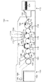
図17は、本発明の実施形態に係るインクジェット記録装置の構成例を示す全体構成図である。本例のインクジェット記録装置100は、主として、給紙部112、処理液付与部114、描画部116、乾燥部118、定着部120、及び排紙部122から構成されている。インクジェット記録装置100は、描画部116のドラム(描画ドラム170)に保持された記録媒体124(「被描画媒体」に相当、以下、便宜上「用紙」と呼ぶ場合がある。)にインクジェットヘッド172M,172K,172C,172Yから複数色のインクを打滴して所望のカラー画像を形成するシングルパス方式のインクジェット記録装置であり、インクの打滴前に記録媒体124上に処理液(ここでは凝集処理液)を付与し、処理液とインク液を反応させて記録媒体124上に画像形成を行う2液反応(凝集)方式が適用されたドロップオンデマンドタイプの画像形成装置である。
FIG. 17 is an overall configuration diagram illustrating a configuration example of the ink jet recording apparatus according to the embodiment of the present invention. The ink
(給紙部)
給紙部112には、枚葉紙である記録媒体124が積層されており、給紙部112の給紙トレイ150から記録媒体124が一枚ずつ処理液付与部114に給紙される。本例では、記録媒体124として、枚葉紙(カット紙)を用いるが、連続用紙(ロール紙)から必要なサイズに切断して給紙する構成も可能である。
(Paper Feeder)
A
(処理液付与部)
処理液付与部114は、記録媒体124の記録面に処理液を付与する機構である。処理液は、描画部116で付与されるインク中の色材(本例では顔料)を凝集させる色材凝集剤を含んでおり、この処理液とインクとが接触することによって、インクは色材と溶媒との分離が促進される。
(Processing liquid application part)
The processing
処理液付与部114は、給紙胴152、処理液ドラム(「プレコート胴」とも言う)154、及び処理液塗布装置156を備えている。処理液ドラム154は、記録媒体124を保持し、回転搬送させるドラムである。処理液ドラム154は、その外周面に爪形状の保持手段(グリッパー)155を備え、この保持手段155の爪と処理液ドラム154の周面の間に記録媒体124を挟み込むことによって記録媒体124の先端を保持できるようになっている。処理液ドラム154は、その外周面に吸引孔を設けるとともに、吸引孔から吸引を行う吸引手段を接続してもよい。これにより記録媒体124を処理液ドラム154の周面に密着保持することができる。
The processing
処理液塗布装置156は、処理液が貯留された処理液容器と、この処理液容器の処理液に一部が浸漬されたアニックスローラ(計量ローラ)と、該アニックスローラと処理液ドラム154上の記録媒体124に圧接されて計量後の処理液を記録媒体124に転移するゴムローラとで構成される。本実施形態では、ローラによる塗布方式を適用した構成を例示したが、これに限定されず、例えば、スプレー方式、インクジェット方式などの各種方式を適用することも可能である。
The processing
処理液付与部114で処理液が付与された記録媒体124は、処理液ドラム154から中間搬送部126を介して描画部116の描画ドラム170へ受け渡される。
The
(描画部)
描画部116は、描画ドラム(「描画胴」或いは「ジェッティング胴」とも言う)170、用紙抑えローラ174、及びインクジェットヘッド172M,172K,172C,172Yを備えている。各色のインクジェットヘッド172M,172K,172C,172Y及びその制御装置として、図1で説明したインクジェットヘッド10の構成と図16で説明したヘッド制御部70の構成が採用されている。
(Drawing part)
The
描画ドラム170は、処理液ドラム154と同様に、その外周面に爪形状の保持手段(グリッパー)171を備える。描画ドラム170の周面には、図示しない吸着穴が所定のパターンで多数形成されており、この吸着穴からエアが吸引されることにより、記録媒体124が描画ドラム170の周面に吸着保持される。なお、負圧吸引によって記録媒体124を吸引吸着する構成に限らず、例えば、静電吸着により、記録媒体124を吸着保持する構成とすることもできる。
Similar to the treatment liquid drum 154, the drawing
インクジェットヘッド172M,172K,172C,172Yはそれぞれ、記録媒体124における画像形成領域の最大幅に対応する長さを有するフルライン型のインクジェット方式の記録ヘッドであり、そのインク吐出面には、画像形成領域の全幅にわたってインク吐出用のノズルが複数配列されたノズル列(2次元配列ノズル)が形成されている。各インクジェットヘッド172M,172K,172C,172Yは、記録媒体124の搬送方向(描画ドラム170の回転方向)と直交する方向に延在するように設置される。
Each of the inkjet heads 172M, 172K, 172C, and 172Y is a full-line inkjet recording head having a length corresponding to the maximum width of the image forming area in the
各インクジェットヘッド172M,172K,172C,172Yには、対応する色インクのカセット(インクカートリッジ)が取り付けられる。インクジェットヘッド172M,172K,172C,172Yから、描画ドラム170の外周面に保持された記録媒体124の記録面に向かってインク滴が吐出される。
A corresponding color ink cassette (ink cartridge) is attached to each of the inkjet heads 172M, 172K, 172C, and 172Y. Ink droplets are ejected from the inkjet heads 172M, 172K, 172C, and 172Y toward the recording surface of the
これにより、予め記録面に付与された処理液にインクが接触し、インク中に分散する色材(顔料)が凝集され、色材凝集体が形成される。インクと処理液の反応の一例として、本実施形態では、処理液に酸を含有させPHダウンにより顔料分散を破壊し凝集するメカニズムを用い、色材滲み、各色インク間の混色、インク滴の着弾時の液合一による打滴干渉を回避する。こうして、記録媒体124上での色材流れなどが防止され、記録媒体124の記録面に画像が形成される。
As a result, the ink comes into contact with the treatment liquid previously applied to the recording surface, and the color material (pigment) dispersed in the ink is aggregated to form a color material aggregate. As an example of the reaction between the ink and the treatment liquid, in this embodiment, an acid is contained in the treatment liquid, and the pigment dispersion is destroyed and aggregated by the PH down. Avoids droplet ejection interference due to liquid coalescence. Thus, the color material flow on the
各インクジェットヘッド172M,172K,172C,172Yの打滴タイミングは、描画ドラム170に配置された回転速度を検出するエンコーダ(図17中不図示、図18の符号294)に同期させる。このエンコーダの検出信号に基づいて吐出トリガー信号(画素トリガー)が発せされる。これにより、高精度に着弾位置を決定することができる。また、予め描画ドラム170のフレなどによる速度変動を学習し、エンコーダで得られた打滴タイミングを補正して、描画ドラム170のフレ、回転軸の精度、描画ドラム170の外周面の速度に依存せずに打滴ムラを低減させることができる。更に、各インクジェットヘッド172M,172K,172C,172Yのノズル面の清掃、増粘インク排出などのメンテナンス動作は、ヘッドユニットを描画ドラム170から退避させて実施するとよい。
The droplet ejection timing of each
本例では、CMYKの標準色(4色)の構成を例示したが、インク色や色数の組み合わせについては本実施形態に限定されず、必要に応じて淡インク、濃インク、特別色インクを追加してもよい。例えば、ライトシアン、ライトマゼンタなどのライト系インクを吐出するインクジェットヘッドを追加する構成も可能であり、各色ヘッドの配置順序も特に限定はない。 In this example, the configuration of CMYK standard colors (four colors) is illustrated, but the combination of ink colors and the number of colors is not limited to this embodiment, and light ink, dark ink, and special color ink are used as necessary. May be added. For example, it is possible to add an inkjet head that discharges light-colored ink such as light cyan and light magenta, and the arrangement order of the color heads is not particularly limited.
描画部116で画像が形成された記録媒体124は、描画ドラム170から中間搬送部128を介して乾燥部118の乾燥ドラム176へ受け渡される。
The
(乾燥部)
乾燥部118は、色材凝集作用により分離された溶媒に含まれる水分を乾燥させる機構であり、乾燥ドラム(「乾燥胴」とも言う)176、及び溶媒乾燥装置178を備えている。乾燥ドラム176は、処理液ドラム154と同様に、その外周面に爪形状の保持手段(グリッパー)177を備え、この保持手段177によって記録媒体124の先端を保持できるようになっている。
(Drying part)
The drying
溶媒乾燥装置178は、乾燥ドラム176の外周面に対向する位置に配置され、複数のハロゲンヒータ180と、各ハロゲンヒータ180の間にそれぞれ配置された温風噴出しノズル182とで構成される。各温風噴出しノズル182から記録媒体124に向けて吹き付けられる温風の温度と風量、各ハロゲンヒータ180の温度を適宜調節することにより、様々な乾燥条件を実現することができる。乾燥部118で乾燥処理が行われた記録媒体124は、乾燥ドラム176から中間搬送部130を介して定着部120の定着ドラム184へ受け渡される。
The
(定着部)
定着部120は、定着ドラム(「定着胴」とも言う)184、ハロゲンヒータ186、定着ローラ188、及びインラインセンサ190で構成される。定着ドラム184は、処理液ドラム154と同様に、その外周面に爪形状の保持手段(グリッパー)185を備え、この保持手段185によって記録媒体124の先端を保持できるようになっている。
(Fixing part)
The fixing
定着ドラム184の回転により、記録媒体124は記録面が外側を向くようにして搬送され、この記録面に対して、ハロゲンヒータ186による予備加熱と、定着ローラ188による定着処理と、インラインセンサ190による検査が行われる。
With the rotation of the fixing
定着ローラ188は、乾燥させたインクを加熱加圧することによってインク中の自己分散性ポリマー微粒子を溶着し、インクを被膜化させるためのローラ部材であり、記録媒体124を加熱加圧するように構成される。記録媒体124は、定着ローラ188と定着ドラム184との間に挟まれ、所定のニップ圧(例えば、0.15MPa)でニップされ、定着処理が行われる。
The fixing
また、定着ローラ188は、熱伝導性の良いアルミなどの金属パイプ内にハロゲンランプを組み込んだ加熱ローラによって構成され、所定の温度(例えば60〜80℃)に制御される。この加熱ローラで記録媒体124を加熱することによって、インクに含まれるラテックスのTg温度(ガラス転移点温度)以上の熱エネルギーが付与され、ラテックス粒子が溶融される。これにより、記録媒体124の凹凸に押し込み定着が行われるとともに、画像表面の凹凸がレベリングされ、光沢性が得られる。
The fixing
インラインセンサ190は、記録媒体124に記録された画像(テストパターンなども含む)について、吐出不良チェックパターンや画像の濃度、画像の欠陥などを計測するための読取手段であり、CCDラインセンサなどが適用される。
The
上記の如く構成された定着部120によれば、乾燥部118で形成された薄層の画像層内のラテックス粒子が定着ローラ188によって加熱加圧されて溶融されるので、記録媒体124に固定定着させることができる。
According to the fixing
なお、高沸点溶媒及びポリマー微粒子(熱可塑性樹脂粒子)を含んだインクに代えて、紫外線(UV)露光にて重合硬化可能なモノマー成分を含有していてもよい。この場合、インクジェット記録装置100は、ヒートローラによる熱圧定着部(定着ローラ188)の代わりに、記録媒体124上のインクにUV光を露光するUV露光部を備える。このように、UV硬化性樹脂などの活性光線硬化性樹脂を含んだインクを用いる場合には、加熱定着の定着ローラ188に代えて、UVランプや紫外線LD(レーザダイオード)アレイなど、活性光線を照射する手段が設けられる。
In addition, instead of the ink containing the high boiling point solvent and the polymer fine particles (thermoplastic resin particles), a monomer component that can be polymerized and cured by ultraviolet (UV) exposure may be contained. In this case, the
(排紙部)
定着部120に続いて排紙部122が設けられている。排紙部122は、排出トレイ192を備えており、この排出トレイ192と定着部120の定着ドラム184との間に、これらに対接するように渡し胴194、搬送ベルト196、張架ローラ198が設けられている。記録媒体124は、渡し胴194により搬送ベルト196に送られ、排出トレイ192に排出される。搬送ベルト196による用紙搬送機構の詳細は図示しないが、印刷後の記録媒体124は無端状の搬送ベルト196間に渡されたバー(不図示)のグリッパーによって用紙先端部が保持され、搬送ベルト196の回転によって排出トレイ192の上方に運ばれてくる。
(Output section)
Subsequent to the fixing
また、図17には示されていないが、本例のインクジェット記録装置100には、上記構成の他、各インクジェットヘッド172M,172K,172C,172Yにインクを供給するインク貯蔵/装填部、処理液付与部114に対して処理液を供給する手段を備えるとともに、各インクジェットヘッド172M,172K,172C,172Yのクリーニング(ノズル面のワイピング、パージ、ノズル吸引等)を行うヘッドメンテナンス部や、用紙搬送路上における記録媒体124の位置を検出する位置検出センサ、装置各部の温度を検出する温度センサなどを備えている。
Although not shown in FIG. 17, in addition to the above-described configuration, the ink
<制御系の説明>
図18は、インクジェット記録装置100のシステム構成を示す要部ブロック図である。インクジェット記録装置100は、通信インターフェース270、システムコントローラ272、プリント制御部274、画像バッファメモリ276、ヘッドドライバ278、モータドライバ280、ヒータドライバ282、処理液付与制御部284、乾燥制御部286、定着制御部288、メモリ290、ROM292、エンコーダ294等を備えている。
<Description of control system>
FIG. 18 is a principal block diagram showing the system configuration of the
通信インターフェース270は、ホストコンピュータ350から送られてくる画像データを受信するインターフェース部である。通信インターフェース270にはUSB(Universal Serial Bus)、IEEE1394、イーサネット(登録商標)、無線ネットワークなどのシリアルインターフェースやセントロニクスなどのパラレルインターフェースを適用することができる。この部分には、通信を高速化するためのバッファメモリ(不図示)を搭載してもよい。ホストコンピュータ350から送出された画像データは通信インターフェース270を介してインクジェット記録装置100に取り込まれ、一旦メモリ290に記憶される。
The
メモリ290は、通信インターフェース270を介して入力された画像を一旦格納する記憶手段であり、システムコントローラ272を通じてデータの読み書きが行われる。メモリ290は、半導体素子からなるメモリに限らず、ハードディスクなど磁気媒体を用いてもよい。
The
システムコントローラ272は、中央演算処理装置(CPU)及びその周辺回路等から構成され、所定のプログラムに従ってインクジェット記録装置100の全体を制御する制御装置として機能するとともに、各種演算を行う演算装置として機能する。即ち、システムコントローラ272は、通信インターフェース270、プリント制御部274、モータドライバ280、ヒータドライバ282、処理液付与制御部284等の各部を制御し、ホストコンピュータ350との間の通信制御、メモリ290の読み書き制御等を行うとともに、搬送系のモータ296やヒータ298を制御する制御信号を生成する。
The
ROM292にはシステムコントローラ272のCPUが実行するプログラム及び制御に必要な各種データなどが格納されている。ROM292は、書換不能な記憶手段であってもよいし、EEPROMのような書換可能な記憶手段であってもよい。メモリ290は、画像データの一時記憶領域として利用されるとともに、プログラムの展開領域及びCPUの演算作業領域としても利用される。
The
モータドライバ280は、システムコントローラ272からの指示に従ってモータ296を駆動するドライバである。図18では、装置内の各部に配置される様々なモータを代表して符号296で図示している。例えば、モータ296には、図17の給紙胴152、処理液ドラム154、描画ドラム170、乾燥ドラム176、定着ドラム184、渡し胴194などの回転を駆動するモータ、描画ドラム170の吸引孔から負圧吸引するためのポンプの駆動モータ、インクジェットヘッド172M,172K,172C,172Yのヘッドユニットを、描画ドラム170外のメンテナンスエリアに移動させる退避機構のモータ、などが含まれている。
The
ヒータドライバ282は、システムコントローラ272からの指示に従って、ヒータ298を駆動するドライバである。図18では、装置内の各部に配置される様々なヒータを代表して符号298で図示している。例えば、ヒータ298には、給紙部112において記録媒体124を予め適温に加熱しておくための不図示のプレヒータ、などが含まれている。
The
プリント制御部274は、システムコントローラ272の制御にしたがい、メモリ290内の画像データから印字制御用の信号を生成するための各種加工、補正などの処理を行う信号処理機能を有し、生成した印字データ(ドットデータ)をヘッドドライバ278に供給する制御部である。
The
ドットデータは、一般に多階調の画像データに対して色変換処理、ハーフトーン処理を行って生成される。色変換処理は、sRGBなどで表現された画像データ(例えば、RGB各色について8ビットの画像データ)をインクジェット記録装置100で使用するインクの各色の色データ(本例では、KCMYの色データ)に変換する処理である。 The dot data is generally generated by performing color conversion processing and halftone processing on multi-tone image data. In the color conversion process, image data expressed in sRGB or the like (for example, 8-bit image data for each color of RGB) is converted into color data for each color of ink used in the inkjet recording apparatus 100 (in this example, color data of KCMY). It is a process to convert.
ハーフトーン処理は、色変換処理により生成された各色の色データに対して誤差拡散法や閾値マトリクス等の処理で各色のドットデータ(本例では、KCMYのドットデータ)に変換する処理である。 The halftone process is a process of converting the color data of each color generated by the color conversion process into dot data of each color (KCMY dot data in this example) by processes such as an error diffusion method and a threshold matrix.
プリント制御部274において所要の信号処理が施され、得られたドットデータに基づいて、ヘッドドライバ278を介してヘッド250(各色のインクジェットヘッド172M,172K,172C,172Yを包括して符号250と記載)のインク液滴の吐出量や吐出タイミングの制御が行われる。これにより、所望のドットサイズやドット配置が実現される。ここで言うドットデータは、「ノズル制御データ」に相当している。
Necessary signal processing is performed in the
プリント制御部274には画像バッファメモリ(不図示)が備えられており、プリント制御部274における画像データ処理時に画像データやパラメータなどのデータが画像バッファメモリに一時的に格納される。また、プリント制御部274とシステムコントローラ272とを統合して1つのプロセッサで構成する態様も可能である。
The
画像入力から印字出力までの処理の流れを概説すると、印刷すべき画像のデータは、通信インターフェース270を介して外部から入力され、メモリ290に蓄えられる。この段階では、例えば、RGBの画像データがメモリ290に記憶される。インクジェット記録装置100では、インク(色材) による微細なドットの打滴密度やドットサイズを変えることによって、人の目に疑似的な連続階調の画像を形成するため、入力されたデジタル画像の階調(画像の濃淡)をできるだけ忠実に再現するようなドットパターンに変換する必要がある。そのため、メモリ290に蓄えられた元画像(RGB)のデータは、システムコントローラ272を介してプリント制御部274に送られ、該プリント制御部274において閾値マトリクスや誤差拡散法などを用いたハーフトーニング処理によってインク色ごとのドットデータに変換される。即ち、プリント制御部274は、入力されたRGB画像データをK,C,M,Yの4色のドットデータに変換する処理を行う。こうして、プリント制御部274で生成されたドットデータは、画像バッファメモリ(不図示)に蓄えられる。
An overview of the flow of processing from image input to print output is as follows. Image data to be printed is input from the outside via the
ヘッドドライバ278は、プリント制御部274から与えられる印字データ(即ち、画像バッファメモリ276に記憶されたドットデータ)に基づき、ヘッド250の各ノズルに対応する圧力発生素子30を駆動するための駆動信号を出力する。ヘッドドライバ278にはヘッドの駆動条件を一定に保つためのフィードバック制御系を含んでいてもよい。
The
ヘッドドライバ278から出力された駆動信号がヘッド250に加えられることによって、該当するノズルからインクが吐出される。記録媒体124を所定の速度で搬送しながらヘッド250からのインク吐出を制御することにより、記録媒体124上に画像が形成される。なお、本例に示すインクジェット記録装置100は、ヘッド250(ヘッドモジュール)に対して、モジュール単位で共通の駆動電力波形信号を印加し、各ノズル22の吐出タイミングに応じて各圧力発生素子30の個別電極に接続されたスイッチ(図2の符号62)のオンオフを切り換えることで、各圧力発生素子30に対応するノズル22からインクを吐出させる駆動方式が採用されている。
When the drive signal output from the
このヘッドドライバ278、プリント制御部274(画像バッファメモリ内蔵)の部分が図16で説明したヘッド制御部70に相当する。また、図18のシステムコントローラ272が図16で説明した上位データ制御部80に相当する。
The
処理液付与制御部284は、システムコントローラ272からの指示にしたがい、処理液塗布装置156(図16参照)の動作を制御する。乾燥制御部286は、システムコントローラ272からの指示にしたがい、溶媒乾燥装置178(図16参照)の動作を制御する。
The treatment
定着制御部288は、システムコントローラ272からの指示にしたがい、定着部120のハロゲンヒータ186や定着ローラ188(図16参照)から成る定着加圧部299の動作を制御する。
The fixing
インラインセンサ190は、図16で説明したように、イメージセンサを含むブロックであり、記録媒体124に印字された画像を読み取り、所要の信号処理などを行って印字状況(吐出の有無、打滴のばらつき、光学濃度など)を検出し、その検出結果をシステムコントローラ272及びプリント制御部274に提供する。
As described with reference to FIG. 16, the in-
プリント制御部274は、インラインセンサ190から得られる情報に基づいてヘッド250に対する各種補正(不吐出補正や濃度補正など)を行うとともに、必要に応じて予備吐出や吸引、ワイピング等のクリーニング動作(ノズル回復動作)を実施する制御を行う。
The
<変形例1>
上記実施形態では、記録媒体124に直接インク滴を打滴して画像を形成する方式(直接記録方式)のインクジェット記録装置を説明したが、本発明の適用範囲はこれに限定されず、一旦、中間転写体上に画像(一次画像)を形成し、その画像を転写部において記録紙に対して転写することで最終的な画像形成を行う中間転写型の画像形成装置についても本発明を適用することができる。
<
In the above embodiment, an ink jet recording apparatus of a method (direct recording method) in which an ink droplet is directly formed on the
また、上記実施形態では、記録媒体の全幅に対応する長さのノズル列を有するページワイドのフルライン型ヘッドを用いたインクジェット記録装置(1回の副走査によって画像を完成させるシングルパス方式の画像形成装置)を説明したが、本発明の適用範囲はこれに限定されず、シリアル型(シャトルスキャン型)ヘッドなど、短尺の記録ヘッドを移動させながら、複数回のヘッド走査により画像記録を行うインクジェット記録装置についても本発明を適用できる。 Further, in the above embodiment, an inkjet recording apparatus using a page-wide full-line head having a nozzle row having a length corresponding to the entire width of the recording medium (single-pass image for completing an image by one sub-scanning). However, the scope of application of the present invention is not limited to this, and an inkjet that performs image recording by scanning a plurality of heads while moving a short recording head such as a serial (shuttle scan) head. The present invention can also be applied to a recording apparatus.
<ヘッドと用紙を相対移動させる手段について>
上述の実施形態では、停止したヘッドに対して記録媒体を搬送する構成を例示したが、本発明の実施に際しては、停止した記録媒体(被描画媒体)に対してヘッドを移動させる構成も可能である。
<Means for moving the head and paper relative to each other>
In the above-described embodiment, the configuration in which the recording medium is transported to the stopped head is exemplified. However, in the implementation of the present invention, a configuration in which the head is moved with respect to the stopped recording medium (the drawing medium) is also possible. is there.
<記録媒体について>
「記録媒体」は、インクジェットヘッドから吐出された液滴によってドットが記録される媒体の総称であり、印字媒体、被記録媒体、被画像形成媒体、受像媒体、被吐出媒体など様々な用語で呼ばれるものが含まれる。本発明の実施に際して、記録媒体の材質や形状等は、特に限定されず、連続用紙、カット紙、シール用紙、OHPシート等の樹脂シート、フィルム、布、不織布、配線パターン等が形成されるプリント基板、ゴムシート、その他材質や形状を問わず、様々な媒体に適用できる。
<About recording media>
“Recording medium” is a general term for media on which dots are recorded by droplets ejected from an inkjet head, and is called by various terms such as a printing medium, a recording medium, an image forming medium, an image receiving medium, and a discharging medium. Things are included. In the practice of the present invention, the material, shape, etc. of the recording medium are not particularly limited, and a print on which a resin sheet such as continuous paper, cut paper, seal paper, OHP sheet, film, cloth, nonwoven fabric, wiring pattern, or the like is formed. It can be applied to various media regardless of the substrate, rubber sheet, and other materials and shapes.
<吐出方式について>
なお、インクジェットヘッドにおける各ノズルから液滴を吐出させるための吐出用の圧力(吐出エネルギー)を発生させる手段は、ピエゾアクチュエータ(圧電素子)に限らない。圧電素子の他、静電アクチュエータ、サーマル方式(ヒータの加熱による膜沸騰の圧力を利用してインクを吐出させる方式)におけるヒータ(加熱素子)や他の方式による各種アクチュエータなど様々な圧力発生素子(吐出エネルギー発生素子)を適用し得る。ヘッドの吐出方式に応じて、相応のエネルギー発生素子が流路構造体に設けられる。
<Discharge method>
The means for generating discharge pressure (discharge energy) for discharging droplets from each nozzle in the inkjet head is not limited to a piezo actuator (piezoelectric element). In addition to piezoelectric elements, various pressure generating elements (such as heaters (heating elements) in electrostatic actuators, thermal methods (methods that eject ink using the pressure of film boiling by heating of the heaters), and various other actuators) A discharge energy generating element) can be applied. Corresponding energy generating elements are provided in the flow path structure according to the ejection method of the head.
<サーマル方式への適応例>
サーマル方式のイジェクタを備えた液体吐出ヘッドの場合、実際の吐出を行う駆動用の波形部(主波形)を印加する前に、吐出しない程度の副波形を与えることで、後続の主波形を印加しても吐出しない構成を実現できる。
<Application example to thermal method>
In the case of a liquid ejection head equipped with a thermal ejector, the subsequent main waveform is applied by giving a sub-waveform that does not eject before applying the drive waveform section (main waveform) for actual ejection. Even if it does not discharge, the structure can be realized.
これは次の原理による。すなわち、サーマ方式の吐出原理は、ヒータ(発熱素子)に電流を流し、表面に接するインク液が蒸発して(沸騰させて)、その勢いで滴が飛ぶ、というものである。この加熱沸騰による吐出効率を低下させるような、駆動制御(電流)処理を行うことにより、吐出を抑制することができる。 This is based on the following principle. That is, the therma-type ejection principle is such that an electric current is passed through a heater (heat generating element), the ink liquid in contact with the surface evaporates (boils), and droplets fly at that momentum. Discharge can be suppressed by performing drive control (current) processing that lowers the discharge efficiency due to heating and boiling.
例えば、主波形に先行して、最初に微弱な電流を流したときに、インクはヒータの界面から離れているので、後続の主波形の印加で発生する熱はインク液に伝わりにくくなる。 For example, when a weak current is first applied prior to the main waveform, the ink is separated from the heater interface, so that heat generated by the application of the subsequent main waveform is less likely to be transmitted to the ink liquid.
このように、主波形の印加に先立ち、副波形の印加で液が吐出されない程度に、僅かにヒータの表面から液(インク)を離す(浮かす)ような、電流を与える。その後、主波形が印加される構成として、主波形印加による熱がインクに伝わりにくくする。 Thus, prior to the application of the main waveform, an electric current that slightly separates (floats) the liquid (ink) from the surface of the heater is applied to the extent that the liquid is not discharged by the application of the sub waveform. Thereafter, as a configuration in which the main waveform is applied, heat due to the application of the main waveform is hardly transmitted to the ink.
こうして、副波形Aと主波形が連続して印加されたときに、インクが吐出されない状態を実現できる。 In this way, it is possible to realize a state in which ink is not ejected when the sub waveform A and the main waveform are continuously applied.
<装置応用例>
上記の実施形態では、グラフィック印刷用のインクジェット記録装置への適用を例に説明したが、本発明の適用範囲はこの例に限定されない。例えば、電子回路の配線パターンを描画する配線描画装置、各種デバイスの製造装置、吐出用の機能性液体として樹脂液を用いるレジスト印刷装置、カラーフィルター製造装置、マテリアルデポジション用の材料を用いて微細構造物を形成する微細構造物形成装置など、液状機能性材料を用いて様々な形状やパターンを描画するインクジェット装置に広く適用できる。
<Device application example>
In the above embodiment, application to an inkjet recording apparatus for graphic printing has been described as an example, but the scope of application of the present invention is not limited to this example. For example, a wiring drawing apparatus for drawing a wiring pattern of an electronic circuit, a manufacturing apparatus for various devices, a resist printing apparatus that uses a resin liquid as a functional liquid for ejection, a color filter manufacturing apparatus, and a material deposition material. The present invention can be widely applied to an inkjet apparatus that draws various shapes and patterns using a liquid functional material, such as a fine structure forming apparatus that forms a structure.
なお、本発明は以上説明した実施形態に限定されるものではなく、本発明の技術的思想内で当該分野の通常の知識を有するものにより、多くの変形が可能である。 The present invention is not limited to the embodiments described above, and many modifications can be made by those having ordinary knowledge in the field within the technical idea of the present invention.
<付記;開示する発明の態様について>
上記に詳述した発明の実施形態についての記載から把握されるとおり、本明細書は少なくとも以下に示す発明を含む多様な技術思想の開示を含んでいる。
<Appendix; Aspects of Disclosure of Invention>
As will be understood from the description of the embodiments of the invention described in detail above, the present specification includes disclosure of various technical ideas including at least the invention described below.
(発明1):液滴を吐出する吐出口となる複数のノズルと、前記複数の前記ノズルから液滴を吐出させる吐出エネルギーを発生させる手段として各ノズルのそれぞれに対応して設けられている圧力発生素子と、前記各ノズルに対応する複数の前記圧力発生素子のそれぞれに接続される複数のスイッチを含んだ回路制御素子と、前記各圧力発生素子に繋がる前記複数のスイッチの一端に供給する電圧波形を出力する電圧波形生成手段と、前記複数のスイッチの開閉を制御する制御信号を出力するスイッチ制御手段と、を備え、前記電圧波形生成手段で生成される前記電圧波形は、前記制御信号に基づく前記スイッチの開閉制御によって当該電圧波形の一部が前記圧力発生素子に印加された場合に、当該一部の波形部分が印加された圧力発生素子に対応するノズルから液体が吐出される一方、前記電圧波形の全体が前記圧力発生素子に印加された場合に、当該電圧波形全体が印加された圧力発生素子に対応するノズルから液体が吐出されない波形であることを特徴とする液体吐出装置。 (Invention 1): A plurality of nozzles serving as ejection openings for ejecting droplets, and pressures provided for each nozzle as means for generating ejection energy for ejecting droplets from the plurality of nozzles A voltage supplied to one end of the plurality of switches connected to each of the pressure generating elements, and a circuit control element including a plurality of switches connected to each of the plurality of pressure generating elements corresponding to each of the nozzles Voltage waveform generating means for outputting a waveform, and switch control means for outputting a control signal for controlling opening and closing of the plurality of switches, and the voltage waveform generated by the voltage waveform generating means is added to the control signal. When a part of the voltage waveform is applied to the pressure generating element by the opening / closing control of the switch based on, the pressure generating element to which the part of the waveform is applied While the liquid is discharged from the corresponding nozzle, when the entire voltage waveform is applied to the pressure generating element, the liquid is not discharged from the nozzle corresponding to the pressure generating element to which the entire voltage waveform is applied. A liquid ejecting apparatus comprising:
発明1によれば、圧力発生素子に繋がるスイッチの開閉を制御して、圧力発生素子に対して電圧波形の一部を印加するとノズルから液滴の吐出が行われる。スイッチが制御不能に陥り、常時オン(常時閉)となったような場合、このスイッチにつがなる圧力発生素子には電圧波形の全体が印加されることになる。このとき対応するノズルから液は吐出しない。 According to the first aspect of the present invention, when a part of the voltage waveform is applied to the pressure generating element by controlling the opening and closing of the switch connected to the pressure generating element, the droplet is ejected from the nozzle. When the switch becomes uncontrollable and is normally on (normally closed), the entire voltage waveform is applied to the pressure generating element connected to the switch. At this time, no liquid is discharged from the corresponding nozzle.
(発明2):発明1に記載の液体吐出装置において、前記電圧波形は、前記ノズルから液体を吐出させる吐出駆動用の主波形部と、前記主波形部との組み合わせによって吐出を抑制する吐出抑制用の副波形部と、を含むことを特徴とする。
(Invention 2): The liquid ejection device according to
主波形部と副波形部とが時分割で組み合わされた電圧波形を用いる構成を採用する態様である。この態様によれば、主波形部のみを圧力発生素子に印加すると吐出を行うことができる。また、主波形部と副波形部とをともに印加した場合には、吐出が行われない。 In this aspect, a configuration using a voltage waveform in which a main waveform portion and a sub waveform portion are combined in a time division manner is employed. According to this aspect, when only the main waveform portion is applied to the pressure generating element, ejection can be performed. Further, when both the main waveform portion and the sub waveform portion are applied, ejection is not performed.
(発明3):発明2に記載の液体吐出装置において、前記副波形部は、前記主波形部に先行する波形部分であることを特徴とする。
(Invention 3): In the liquid ejection device according to
主波形部による吐出を抑制するための副波形部は、主波形部の前、或いは、後ろ、若しくは、前後両方に配置する構成が考えられる。 The sub waveform part for suppressing the discharge by the main waveform part can be considered to be arranged in front of, behind, or both before and after the main waveform part.
発明3のように主波形部の手前に副波形部を付加した構成の電圧波形を採用する構成が好ましい。 A configuration in which a voltage waveform having a configuration in which a sub-waveform portion is added before the main waveform portion as in the third aspect is preferable.
(発明4):発明2又は3に記載の液体吐出装置において、前記副波形部の印加によって発生する圧力波が、前記主波形部の印加によって発生する圧力波の少なくとも一部を打ち消すように、前記副波形部と前記主波形部とが組み合わされて前記電圧波形が形成されていることを特徴とする。
(Invention 4): In the liquid ejection device according to
かかる態様によれば、主波形部の印加による吐出効率を低下させることができ、主波形部と副波形部とがともに印加された場合に、吐出しない状態とすることができる。 According to such an aspect, the ejection efficiency due to the application of the main waveform portion can be reduced, and when both the main waveform portion and the sub waveform portion are applied, it is possible to make a state in which ejection is not performed.
(発明5):発明4に記載の液体吐出装置において、前記ノズルと、前記ノズルに連通する圧力室と、前記圧力室に対応して設けられた前記圧力発生素子と、を含んで構成されるイジェクタを複数備えた液体吐出ヘッドを有し、前記圧力室内に充填される液体を含んだ圧力室系の固有周期をTcとするとき、前記副波形部を構成する波形要素のうち電圧の立ち下げ、又は立ち上げのいずれかの電圧変化をもたらす第1波形要素と、前記主波形部を構成する波形要素のうち前記第1波形要素と同じ方向の電圧変化をもたらす第2波形要素とが、(2n+1)×(Tc/2)の時間間隔だけ離れていること(ただし、nは0以上の整数)を特徴とする。
(Invention 5): The liquid ejection device according to
副波形部と主波形部の立ち下げ部同士、或いは、立ち上げ部同士のように、同じ方向の電圧変化部分を半固有周期(Tc/2)の奇数倍だけ離した波形構成とする態様である。この態様により、圧力波を効果的にキャンセルすることができる。 In a mode in which the voltage change portions in the same direction are separated by an odd multiple of the semi-natural period (Tc / 2), such as between the falling portions of the sub waveform portion and the main waveform portion, or between the rising portions. is there. By this aspect, a pressure wave can be canceled effectively.
(発明6):発明2から5のいずれか1項に記載の液体吐出装置において、前記副波形部の電圧振幅は、前記主波形部の電圧振幅以上であることを特徴とする。
(Invention 6): In the liquid ejection device according to any one of
かかる態様によれば、主波形部の吐出効率を副波形部で効果的に低下させることができる。 According to this aspect, the discharge efficiency of the main waveform portion can be effectively reduced at the sub waveform portion.
(発明7):発明2から6のいずれか1項に記載の液体吐出装置において、前記副波形部の最低電圧は、前記主波形部の最低電圧以下であることを特徴とする。
(Invention 7): In the liquid ejection device according to any one of
かかる態様によれば、主波形部の吐出効率を副波形部で効果的に低下させることができる。 According to this aspect, the discharge efficiency of the main waveform portion can be effectively reduced at the sub waveform portion.
(発明8):発明4に記載の液体吐出装置において、前記ノズルと、前記ノズルに連通する圧力室と、前記圧力室に対応して設けられた前記圧力発生素子と、を含んで構成されるイジェクタを複数備えた液体吐出ヘッドを有し、前記圧力室内に充填される液体を含んだ圧力室系の固有周期をTcとするとき、前記副波形部を構成する波形要素のうち電圧の立ち下げ、又は立ち上げのいずれかの電圧変化をもたらす第1波形要素と、前記主波形部を構成する波形要素のうち前記第1波形要素と逆方向の電圧変化をもたらす第2波形要素とが、(n+1)×Tcの時間間隔だけ離れていること(ただし、nは0以上の整数)を特徴とする。
(Invention 8): The liquid ejection device according to
副波形部の立ち上げ部と主波形部の立ち下げ部、或いは、副波形部の立ち下げ部と主波形部の立ち上げ部のように、逆方向の電圧変化部を固有周期Tcの整数倍だけ離した波形構成とする態様である。 The voltage changing part in the reverse direction is an integral multiple of the natural period Tc, such as the rising part of the sub waveform part and the falling part of the main waveform part, or the rising part of the sub waveform part and the rising part of the main waveform part. This is a mode in which the waveforms are separated by a distance.
この態様により、圧力波を効果的にキャンセルすることができる。 By this aspect, a pressure wave can be canceled effectively.
(発明9):発明2から8のいずれか1項に記載の液体吐出装置において、前記電圧波形は、1記録周期内に複数の前記主波形部と、複数の前記副波形部と、を含んでいることを特徴とする。
(Invention 9): In the liquid ejecting apparatus according to any one of
副波形と主波形の組み合わせを複数組つなげ合わせた波形構成を採用することもできる。 It is also possible to adopt a waveform configuration in which a plurality of combinations of sub waveforms and main waveforms are combined.
これら複数の主波形のうち、圧力発生素子に印加する主波形の個数を変更することによって、吐出液滴量を変更することができる。 By changing the number of main waveforms applied to the pressure generating element among the plurality of main waveforms, the amount of ejected droplets can be changed.
(発明10):発明2から9のいずれか1項に記載の液体吐出装置において、前記副波形部の電圧立ち上げ部分は、ステップ状に電圧を段階的に上昇させる波形要素で構成されていることを特徴とする。
(Invention 10): In the liquid ejection device according to any one of
かかる態様によれば、副波形部の吐出効率が下がり、副波形部印加時の吐出を効果的に抑止することができる。 According to such an aspect, the discharge efficiency of the sub-waveform portion is lowered, and discharge during application of the sub-waveform portion can be effectively suppressed.
(発明11):発明2から9のいずれか1項に記載の液体吐出装置において、前記副波形部の電圧立ち上げ部分は、S字カーブに沿うように電圧を変化させる波形要素で構成されていることを特徴とする。
(Invention 11): In the liquid ejection device according to any one of
かかる態様によれば、副波形部の吐出効率が下がり、副波形部印加時の吐出を効果的に抑止することができる。 According to such an aspect, the discharge efficiency of the sub-waveform portion is lowered, and discharge during application of the sub-waveform portion can be effectively suppressed.
(発明12):発明3に記載の液体吐出装置において、前記副波形部が前記圧力発生素子に印加されると、当該圧力発生素子に対応するノズル内部に気泡が巻き込まれ、当該気泡によって、後続の前記主波形部の印加による吐出を抑止することを特徴とする。
(Invention 12): In the liquid ejection device according to
かかる態様によれば、主波形部と副波形部とがともに印加された場合に、吐出しない状態を実現することができる。 According to this aspect, when both the main waveform portion and the sub waveform portion are applied, it is possible to realize a state in which ejection is not performed.
(発明13):発明1から12のいずれか1項に記載の液体吐出装置と、前記ノズルから吐出された液滴を付着させる媒体を搬送する媒体搬送手段と、備えたことを特徴とするインクジェット装置。
(Invention 13): Inkjet comprising: the liquid ejection device according to any one of
(発明14):液滴を吐出する吐出口となる複数のノズルと、前記複数の前記ノズルから液滴を吐出させる吐出エネルギーを発生させる手段として各ノズルのそれぞれに対応して設けられている圧力発生素子と、前記各ノズルに対応する複数の前記圧力発生素子のそれぞれに接続される複数のスイッチを含んだ回路制御素子と、前記回路制御素子に接続され、前記圧力発生素子に繋がる前記スイッチの一端に供給する電圧波形を出力する電圧波形生成手段と、前記複数のスイッチの開閉を制御する制御信号を出力するスイッチ制御手段と、を備えた液体吐出装置の吐出制御方法であって、前記電圧波形の全体が前記圧力発生素子に印加された場合に、前記ノズルから液体が吐出されないように構成された前記電圧波形を前記スイッチの一端に供給し、前記制御信号により前記スイッチの開閉制御を行うことによって前記電圧波形の一部を前記圧力発生素子に印加し、当該一部の波形部分が印加された圧力発生素子に対応するノズルから液体の吐出を行うことを特徴とする液体吐出装置の吐出制御方法。 (Invention 14): A plurality of nozzles serving as discharge ports for discharging droplets, and pressures provided corresponding to the respective nozzles as means for generating discharge energy for discharging droplets from the plurality of nozzles A generation element, a circuit control element including a plurality of switches connected to each of the plurality of pressure generation elements corresponding to each of the nozzles, and a switch connected to the circuit control element and connected to the pressure generation element A discharge control method for a liquid discharge apparatus, comprising: a voltage waveform generation unit that outputs a voltage waveform supplied to one end; and a switch control unit that outputs a control signal for controlling opening and closing of the plurality of switches. When the entire waveform is applied to the pressure generating element, the voltage waveform configured to prevent liquid from being discharged from the nozzle is applied to one end of the switch. A part of the voltage waveform is applied to the pressure generating element by performing opening / closing control of the switch by the control signal, and liquid is supplied from the nozzle corresponding to the pressure generating element to which the part of the waveform part is applied. A discharge control method for a liquid discharge apparatus, wherein the discharge is performed.
発明14において、発明2から12の特徴を適宜組み合わせる態様も可能である。また、発明14のインクジェット記録方法を実施することによって、印刷物や回路基板、デバイス、微細構造物などを製造することができる。したがって、発明14の方法発明は、これら印刷物等の製造方法という観点で把握することも可能である。
In the
10…インクジェットヘッド、12a、12b…ヘッドモジュール、20…イジェクタ、22…ノズル、24…圧力室、30…圧力発生素子、60…回路制御素子、62…スイッチ、64…インクジェットヘッド制御回路基板、70…ヘッド制御部、76…波形メモリ、78…駆動電圧制御回路、100…インクジェット記録装置、124…記録媒体、170…描画ドラム、172M,172K,172C,172Y…インクジェットヘッド、272…システムコントローラ、280…プリント制御部
DESCRIPTION OF
Claims (14)
前記複数の前記ノズルから液滴を吐出させる吐出エネルギーを発生させる手段として各ノズルのそれぞれに対応して設けられている圧力発生素子と、
前記各ノズルに対応する複数の前記圧力発生素子のそれぞれに接続される複数のスイッチを含んだ回路制御素子と、
前記各圧力発生素子に繋がる前記複数のスイッチの一端に供給する電圧波形を出力する電圧波形生成手段と、
前記複数のスイッチの開閉を制御する制御信号を出力するスイッチ制御手段と、
を備え、
前記電圧波形生成手段で生成される前記電圧波形は、前記制御信号に基づく前記スイッチの開閉制御によって当該電圧波形の一部が前記圧力発生素子に印加された場合に、当該一部の波形部分が印加された圧力発生素子に対応するノズルから液体が吐出される一方、前記電圧波形の全体が前記圧力発生素子に印加された場合に、当該電圧波形全体が印加された圧力発生素子に対応するノズルから液体が吐出されない波形であることを特徴とする液体吐出装置。 A plurality of nozzles serving as ejection openings for ejecting droplets;
A pressure generating element provided corresponding to each of the nozzles as means for generating discharge energy for discharging droplets from the plurality of nozzles;
A circuit control element including a plurality of switches connected to each of the plurality of pressure generating elements corresponding to the nozzles;
Voltage waveform generating means for outputting a voltage waveform to be supplied to one end of the plurality of switches connected to the pressure generating elements;
Switch control means for outputting a control signal for controlling opening and closing of the plurality of switches;
With
The voltage waveform generated by the voltage waveform generation means is such that when a part of the voltage waveform is applied to the pressure generating element by opening / closing control of the switch based on the control signal, When liquid is discharged from the nozzle corresponding to the applied pressure generating element, and the entire voltage waveform is applied to the pressure generating element, the nozzle corresponding to the pressure generating element to which the entire voltage waveform is applied A liquid discharge apparatus having a waveform in which liquid is not discharged from
前記圧力室内に充填される液体を含んだ圧力室系の固有周期をTcとするとき、
前記副波形部を構成する波形要素のうち電圧の立ち下げ、又は立ち上げのいずれかの電圧変化をもたらす第1波形要素と、前記主波形部を構成する波形要素のうち前記第1波形要素と同じ方向の電圧変化をもたらす第2波形要素とが、(2n+1)×(Tc/2)の時間間隔だけ離れていること(ただし、nは0以上の整数)を特徴とする請求項4に記載の液体吐出装置。 A liquid ejection head comprising a plurality of ejectors configured to include the nozzle, a pressure chamber communicating with the nozzle, and the pressure generating element provided corresponding to the pressure chamber;
When the natural period of the pressure chamber system including the liquid filled in the pressure chamber is Tc,
Of the waveform elements constituting the sub-waveform portion, a first waveform element that causes a voltage change of either falling or rising of the voltage, and among the waveform elements constituting the main waveform portion, the first waveform element 5. The second waveform element that causes a voltage change in the same direction is separated by a time interval of (2n + 1) × (Tc / 2) (where n is an integer of 0 or more). Liquid discharge device.
前記圧力室内に充填される液体を含んだ圧力室系の固有周期をTcとするとき、
前記副波形部を構成する波形要素のうち電圧の立ち下げ、又は立ち上げのいずれかの電圧変化をもたらす第1波形要素と、前記主波形部を構成する波形要素のうち前記第1波形要素と逆方向の電圧変化をもたらす第2波形要素とが、(n+1)×Tcの時間間隔だけ離れていること(ただし、nは0以上の整数)を特徴とする請求項4に記載の液体吐出装置。 A liquid ejection head comprising a plurality of ejectors configured to include the nozzle, a pressure chamber communicating with the nozzle, and the pressure generating element provided corresponding to the pressure chamber;
When the natural period of the pressure chamber system including the liquid filled in the pressure chamber is Tc,
Of the waveform elements constituting the sub-waveform portion, a first waveform element that causes a voltage change of either falling or rising of the voltage, and among the waveform elements constituting the main waveform portion, the first waveform element 5. The liquid ejecting apparatus according to claim 4, wherein the second waveform element that causes a voltage change in the reverse direction is separated by a time interval of (n + 1) × Tc (where n is an integer of 0 or more). .
前記ノズルから吐出された液滴を付着させる媒体を搬送する媒体搬送手段と、
を備えたことを特徴とするインクジェット装置。 A liquid ejection device according to any one of claims 1 to 12,
Medium conveying means for conveying a medium to which droplets ejected from the nozzle are attached;
An inkjet apparatus comprising:
前記電圧波形の全体が前記圧力発生素子に印加された場合に、前記ノズルから液体が吐出されないように構成された前記電圧波形を前記スイッチの一端に供給し、
前記制御信号により前記スイッチの開閉制御を行うことによって前記電圧波形の一部を前記圧力発生素子に印加し、当該一部の波形部分が印加された圧力発生素子に対応するノズルから液体の吐出を行うことを特徴とする液体吐出装置の吐出制御方法。 A plurality of nozzles serving as ejection openings for ejecting liquid droplets, pressure generating elements provided corresponding to the respective nozzles as means for generating ejection energy for ejecting liquid droplets from the plurality of nozzles, A circuit control element including a plurality of switches connected to each of the plurality of pressure generating elements corresponding to each nozzle, and a voltage supplied to one end of the switch connected to the circuit control element and connected to the pressure generating element A discharge control method for a liquid discharge apparatus, comprising: voltage waveform generation means for outputting a waveform; and switch control means for outputting a control signal for controlling opening and closing of the plurality of switches.
When the entire voltage waveform is applied to the pressure generating element, the voltage waveform configured to prevent liquid from being discharged from the nozzle is supplied to one end of the switch,
A part of the voltage waveform is applied to the pressure generating element by performing opening / closing control of the switch by the control signal, and liquid is discharged from a nozzle corresponding to the pressure generating element to which the part of the waveform part is applied. A discharge control method for a liquid discharge apparatus.
Priority Applications (3)
| Application Number | Priority Date | Filing Date | Title |
|---|---|---|---|
| JP2011112522A JP5285742B2 (en) | 2011-05-19 | 2011-05-19 | Liquid ejection apparatus, ejection control method thereof, and inkjet apparatus |
| US13/474,385 US8622499B2 (en) | 2011-05-19 | 2012-05-17 | Liquid ejection apparatus and ejection control method for same, and inkjet apparatus |
| CN201210157175.4A CN102785477B (en) | 2011-05-19 | 2012-05-18 | Liquid injection device and ejection control method thereof and ink-jet apparatus |
Applications Claiming Priority (1)
| Application Number | Priority Date | Filing Date | Title |
|---|---|---|---|
| JP2011112522A JP5285742B2 (en) | 2011-05-19 | 2011-05-19 | Liquid ejection apparatus, ejection control method thereof, and inkjet apparatus |
Publications (3)
| Publication Number | Publication Date |
|---|---|
| JP2012240305A JP2012240305A (en) | 2012-12-10 |
| JP2012240305A5 JP2012240305A5 (en) | 2013-04-25 |
| JP5285742B2 true JP5285742B2 (en) | 2013-09-11 |
Family
ID=47151146
Family Applications (1)
| Application Number | Title | Priority Date | Filing Date |
|---|---|---|---|
| JP2011112522A Expired - Fee Related JP5285742B2 (en) | 2011-05-19 | 2011-05-19 | Liquid ejection apparatus, ejection control method thereof, and inkjet apparatus |
Country Status (3)
| Country | Link |
|---|---|
| US (1) | US8622499B2 (en) |
| JP (1) | JP5285742B2 (en) |
| CN (1) | CN102785477B (en) |
Families Citing this family (10)
| Publication number | Priority date | Publication date | Assignee | Title |
|---|---|---|---|---|
| WO2014050604A1 (en) * | 2012-09-27 | 2014-04-03 | 富士フイルム株式会社 | Ink composition, ink set, and image forming method |
| EP3322589B1 (en) * | 2015-07-13 | 2020-09-23 | Jan Franck | Method for controlling a printhead |
| JP6387955B2 (en) * | 2015-12-25 | 2018-09-12 | セイコーエプソン株式会社 | Head unit control circuit |
| JP6584998B2 (en) | 2016-04-19 | 2019-10-02 | 富士フイルム株式会社 | Liquid ejection device and short circuit detection method |
| JP6969170B2 (en) * | 2017-06-16 | 2021-11-24 | セイコーエプソン株式会社 | Liquid discharge head, liquid discharge device, drive control circuit of liquid discharge device, drive method of liquid discharge device |
| EP3720719B1 (en) | 2017-12-05 | 2022-09-21 | Jan Franck | Printing method for a digital printing device |
| CN109094232B (en) * | 2018-08-07 | 2021-09-10 | 北京美科艺数码科技发展有限公司 | Ink-jet printing method |
| US11433664B2 (en) | 2019-02-06 | 2022-09-06 | Hewlett-Packard Development Company, L.P. | Writing a nonvolatile memory to programmed levels |
| DE102019001579B3 (en) | 2019-03-06 | 2020-01-30 | Physik Instrumente (Pi) Gmbh & Co. Kg | Method for operating an electromechanical element, actuator, drive device and motor |
| EP4303008A1 (en) * | 2022-07-08 | 2024-01-10 | Canon Production Printing Holding B.V. | Electric circuit for parallel ejection element failure detection |
Family Cites Families (9)
| Publication number | Priority date | Publication date | Assignee | Title |
|---|---|---|---|---|
| JP3294756B2 (en) * | 1995-08-09 | 2002-06-24 | ブラザー工業株式会社 | Ink jet device |
| US6629741B1 (en) * | 1999-03-11 | 2003-10-07 | Fuji Xerox Co., Ltd. | Ink jet recording head drive method and ink jet recording apparatus |
| JP3687486B2 (en) * | 1999-07-21 | 2005-08-24 | ブラザー工業株式会社 | Ink droplet ejection method and apparatus and storage medium |
| EP1120255A3 (en) * | 2000-01-28 | 2002-01-30 | Seiko Epson Corporation | Generation of driving waveforms to actuate driving elements of print head |
| JP2002127405A (en) * | 2000-10-20 | 2002-05-08 | Hitachi Koki Co Ltd | Ink jet printer and method for detecting failure |
| US6478396B1 (en) * | 2001-03-02 | 2002-11-12 | Hewlett-Packard Company | Programmable nozzle firing order for printhead assembly |
| JP2002337334A (en) * | 2001-05-14 | 2002-11-27 | Seiko Epson Corp | Ink jet recorder and its driving method |
| JP4251912B2 (en) * | 2003-05-02 | 2009-04-08 | 株式会社リコー | Image forming apparatus |
| JP2006142504A (en) | 2004-11-16 | 2006-06-08 | Canon Inc | Ink jet print head |
-
2011
- 2011-05-19 JP JP2011112522A patent/JP5285742B2/en not_active Expired - Fee Related
-
2012
- 2012-05-17 US US13/474,385 patent/US8622499B2/en not_active Expired - Fee Related
- 2012-05-18 CN CN201210157175.4A patent/CN102785477B/en not_active Expired - Fee Related
Also Published As
| Publication number | Publication date |
|---|---|
| US20120293577A1 (en) | 2012-11-22 |
| CN102785477B (en) | 2015-11-18 |
| JP2012240305A (en) | 2012-12-10 |
| US8622499B2 (en) | 2014-01-07 |
| CN102785477A (en) | 2012-11-21 |
Similar Documents
| Publication | Publication Date | Title |
|---|---|---|
| JP5285742B2 (en) | Liquid ejection apparatus, ejection control method thereof, and inkjet apparatus | |
| JP5425246B2 (en) | Liquid ejection head drive device, liquid ejection device, and ink jet recording apparatus | |
| JP5334271B2 (en) | Liquid ejection head drive device, liquid ejection device, and ink jet recording apparatus | |
| JP5410490B2 (en) | LIQUID DISCHARGE HEAD DRIVING DEVICE AND DRIVE METHOD, LIQUID DISCHARGE DEVICE, AND INK JET DEVICE | |
| JP5334321B2 (en) | Inkjet ejection apparatus, inkjet ejection method, and inkjet recording apparatus | |
| JP5625332B2 (en) | Image forming method, image forming apparatus, and program | |
| JP5473704B2 (en) | Test pattern printing method and inkjet recording apparatus | |
| JP5740935B2 (en) | Image forming apparatus and image forming method | |
| JP5591032B2 (en) | Inkjet head drive apparatus and drive method, and inkjet recording apparatus | |
| JP5952704B2 (en) | Head driving method, head driving device, and ink jet recording apparatus | |
| JP2008254199A (en) | Ink jet recorder | |
| JP5968797B2 (en) | Head adjustment method, head drive device, and image forming apparatus | |
| JP5354801B2 (en) | Head control apparatus and inkjet recording apparatus | |
| JP2010214880A (en) | Image forming apparatus and mist catching method | |
| JP2011183550A (en) | Inkjet ejecting apparatus, inkjet ejecting method and inkjet recording apparatus | |
| JP2009231777A (en) | Piezoelectric actuator, liquid discharge head, liquid discharge device, and method of driving piezoelectric actuator | |
| JP2012250472A (en) | State monitoring device of inkjet recording head and inkjet recording apparatus | |
| JP5293408B2 (en) | Image forming apparatus | |
| JP5611117B2 (en) | Inkjet head drive apparatus and drive method, and inkjet recording apparatus | |
| JP2008254201A (en) | Nozzle plate and ink ejection head, image forming apparatus | |
| JP2015058582A (en) | Droplet discharge device | |
| JP2012240306A (en) | Liquid discharge apparatus, discharge control method for same, and inkjet apparatus | |
| JP6828388B2 (en) | Image forming device, image forming method, and program | |
| JP5281881B2 (en) | Image recording apparatus and control method of image recording apparatus | |
| JP2012187894A (en) | Image forming apparatus, image forming method, program, and recording medium |
Legal Events
| Date | Code | Title | Description |
|---|---|---|---|
| A621 | Written request for application examination |
Free format text: JAPANESE INTERMEDIATE CODE: A621 Effective date: 20130129 |
|
| A521 | Request for written amendment filed |
Free format text: JAPANESE INTERMEDIATE CODE: A523 Effective date: 20130308 |
|
| A977 | Report on retrieval |
Free format text: JAPANESE INTERMEDIATE CODE: A971007 Effective date: 20130516 |
|
| TRDD | Decision of grant or rejection written | ||
| A01 | Written decision to grant a patent or to grant a registration (utility model) |
Free format text: JAPANESE INTERMEDIATE CODE: A01 Effective date: 20130521 |
|
| A61 | First payment of annual fees (during grant procedure) |
Free format text: JAPANESE INTERMEDIATE CODE: A61 Effective date: 20130531 |
|
| R150 | Certificate of patent or registration of utility model |
Ref document number: 5285742 Country of ref document: JP Free format text: JAPANESE INTERMEDIATE CODE: R150 |
|
| R250 | Receipt of annual fees |
Free format text: JAPANESE INTERMEDIATE CODE: R250 |
|
| R250 | Receipt of annual fees |
Free format text: JAPANESE INTERMEDIATE CODE: R250 |
|
| R250 | Receipt of annual fees |
Free format text: JAPANESE INTERMEDIATE CODE: R250 |
|
| R250 | Receipt of annual fees |
Free format text: JAPANESE INTERMEDIATE CODE: R250 |
|
| R250 | Receipt of annual fees |
Free format text: JAPANESE INTERMEDIATE CODE: R250 |
|
| R250 | Receipt of annual fees |
Free format text: JAPANESE INTERMEDIATE CODE: R250 |
|
| S533 | Written request for registration of change of name |
Free format text: JAPANESE INTERMEDIATE CODE: R313533 |
|
| R350 | Written notification of registration of transfer |
Free format text: JAPANESE INTERMEDIATE CODE: R350 |
|
| LAPS | Cancellation because of no payment of annual fees |