JP2017192976A - Shim adjustment device and method for die cushion device - Google Patents
Shim adjustment device and method for die cushion device Download PDFInfo
- Publication number
- JP2017192976A JP2017192976A JP2016086075A JP2016086075A JP2017192976A JP 2017192976 A JP2017192976 A JP 2017192976A JP 2016086075 A JP2016086075 A JP 2016086075A JP 2016086075 A JP2016086075 A JP 2016086075A JP 2017192976 A JP2017192976 A JP 2017192976A
- Authority
- JP
- Japan
- Prior art keywords
- die cushion
- shim
- hydraulic
- thickness setting
- pressure
- Prior art date
- Legal status (The legal status is an assumption and is not a legal conclusion. Google has not performed a legal analysis and makes no representation as to the accuracy of the status listed.)
- Granted
Links
Images


Classifications
-
- B—PERFORMING OPERATIONS; TRANSPORTING
- B21—MECHANICAL METAL-WORKING WITHOUT ESSENTIALLY REMOVING MATERIAL; PUNCHING METAL
- B21D—WORKING OR PROCESSING OF SHEET METAL OR METAL TUBES, RODS OR PROFILES WITHOUT ESSENTIALLY REMOVING MATERIAL; PUNCHING METAL
- B21D37/00—Tools as parts of machines covered by this subclass
- B21D37/10—Die sets; Pillar guides
-
- B—PERFORMING OPERATIONS; TRANSPORTING
- B21—MECHANICAL METAL-WORKING WITHOUT ESSENTIALLY REMOVING MATERIAL; PUNCHING METAL
- B21D—WORKING OR PROCESSING OF SHEET METAL OR METAL TUBES, RODS OR PROFILES WITHOUT ESSENTIALLY REMOVING MATERIAL; PUNCHING METAL
- B21D24/00—Special deep-drawing arrangements in, or in connection with, presses
- B21D24/02—Die-cushions
-
- B—PERFORMING OPERATIONS; TRANSPORTING
- B21—MECHANICAL METAL-WORKING WITHOUT ESSENTIALLY REMOVING MATERIAL; PUNCHING METAL
- B21D—WORKING OR PROCESSING OF SHEET METAL OR METAL TUBES, RODS OR PROFILES WITHOUT ESSENTIALLY REMOVING MATERIAL; PUNCHING METAL
- B21D24/00—Special deep-drawing arrangements in, or in connection with, presses
- B21D24/10—Devices controlling or operating blank holders independently, or in conjunction with dies
- B21D24/14—Devices controlling or operating blank holders independently, or in conjunction with dies pneumatically or hydraulically
-
- B—PERFORMING OPERATIONS; TRANSPORTING
- B21—MECHANICAL METAL-WORKING WITHOUT ESSENTIALLY REMOVING MATERIAL; PUNCHING METAL
- B21D—WORKING OR PROCESSING OF SHEET METAL OR METAL TUBES, RODS OR PROFILES WITHOUT ESSENTIALLY REMOVING MATERIAL; PUNCHING METAL
- B21D37/00—Tools as parts of machines covered by this subclass
- B21D37/10—Die sets; Pillar guides
- B21D37/12—Particular guiding equipment, e.g. pliers; Special arrangements for interconnection or cooperation of dies
-
- B—PERFORMING OPERATIONS; TRANSPORTING
- B21—MECHANICAL METAL-WORKING WITHOUT ESSENTIALLY REMOVING MATERIAL; PUNCHING METAL
- B21D—WORKING OR PROCESSING OF SHEET METAL OR METAL TUBES, RODS OR PROFILES WITHOUT ESSENTIALLY REMOVING MATERIAL; PUNCHING METAL
- B21D53/00—Making other particular articles
- B21D53/88—Making other particular articles other parts for vehicles, e.g. cowlings, mudguards
Landscapes
- Engineering & Computer Science (AREA)
- Mechanical Engineering (AREA)
- Shaping Metal By Deep-Drawing, Or The Like (AREA)
- Presses And Accessory Devices Thereof (AREA)
- Control Of Presses (AREA)
Abstract
Description
本発明はダイクッション装置のシム調整装置及び方法に係り、特にダイクッション装置におけるシム調整を効率よく行う技術に関する。 The present invention relates to a shim adjusting device and method for a die cushion device, and more particularly to a technique for efficiently performing shim adjustment in a die cushion device.
ダイクッション装置は、上型と下型(ブランクホルダ)とが材料を介して密着した状態で、ダイクッション待機位置からプレス下死点に至るダイクッションストローク間にクッションパッド(即ち、ブランクホルダ)に対してダイクッション力を付与する。 The die cushion device has a cushion pad (that is, a blank holder) between the die cushion standby position and the press bottom dead center from the die cushion standby position in a state where the upper die and the lower die (blank holder) are in close contact with each other through the material. A die cushion force is applied to the die cushion.
この種のダイクッション装置では、金型毎にブランクホルダによる皺抑え具合を、各部位毎のダイクッションピン−ブランクホルダ間にそれぞれの厚みの金属薄板製シムを手動で挿入する形態で、試行錯誤しながら(成形トライを行い、成形結果を確認しながら、シムの脱/着、厚みの増減等を繰り返し)“シム調整”している。 With this type of die cushion device, trials and errors are carried out by manually inserting a thin sheet metal shim of each thickness between the die cushion pin and the blank holder for each part in order to suppress wrinkles by the blank holder for each die. (Simulation is performed) while repeating the molding try / removal of the shim and the increase / decrease of the thickness while confirming the molding result.
これに対し、ダイクッションパッド上に配設され、ダイクッションピンを支持する複数の油圧シリンダを複数のグループに分割し、その分割された各グループの油圧シリンダ毎に独立して圧力制御を行なうようにしたダイクッションピンの圧力制御装置が提案されている(特許文献1)。 In contrast, a plurality of hydraulic cylinders disposed on the die cushion pad and supporting the die cushion pins are divided into a plurality of groups, and pressure control is performed independently for each of the divided hydraulic cylinders. A die cushion pin pressure control device has been proposed (Patent Document 1).
特許文献1に記載の発明には、2つの目的があり、1つ目は、長期の使用に伴うダイクッションピンの永久変形によるダイクッションピンの長さの偏差に対して、ダイクッション圧力を均等に作用させることにあり、2つ目は鉄板等のプレス絞り成形を行なう場合、被形成物の形状によって適当な成形を行う為に、複数の油圧シリンダのグループ毎にダイクッション圧力を調整可能にすることである。
The invention described in
自動車のボディ生産用ラインの第1工程で使用されるダイクッション装置は、ブランクホルダを支持するダイクッションピンが200本前後存在し、これらのダイクッションピン−ブランクホルダ間の200本前後の各部位毎に任意の厚みの金属薄板製シムを手作業で挿入して行う“シム調整”は、特に新規の金型を使用する場合、金型毎に半日から1日、あるいはそれ以上の期間を要す大変な作業である。 The die cushion device used in the first step of the automobile body production line has around 200 die cushion pins that support the blank holder, and around 200 parts between these die cushion pins and the blank holder. “Shim adjustment”, in which a sheet metal shim with an arbitrary thickness is manually inserted every time, especially when using a new mold, requires half a day to one day or more. It is a tough work.
また、“シム調整”の実績のある金型を使用する場合、“シム調整”の実績が記録されたシム表を見ながら、適宜の厚みの金属薄板製シムを適所に手作業で挿入することになるが、間違った箇所等に金属薄板製シムを挿入したり、挿入する金属薄板製シムの厚みを間違えるという人為的なミスが発生するという問題がある。 In addition, when using a mold with a track record of “shim adjustment”, insert a sheet metal shim of appropriate thickness manually into place while looking at the shim table that records the results of “shim adjustment”. However, there is a problem that an artificial mistake occurs such as inserting a thin sheet metal shim in the wrong place or the wrong thickness of the inserted thin sheet metal shim.
更にプレス機械では、一定数(例えば、8000〜10000)の生産毎に金型が交換され、金型の交換毎に“シム調整”を行う必要があり、シム調整の効率化が要望されているが、現在、“シム調整”の効率化を図ったシム調整装置は存在しない。 Furthermore, in a press machine, it is necessary to change the die every time a certain number (for example, 800 to 10,000) is produced, and it is necessary to perform “shim adjustment” every time the die is changed. However, at present, there is no shim adjusting device for improving the efficiency of “shim adjustment”.
一方、特許文献1に記載のダイクッションピンの圧力制御装置は、油圧シリンダを複数のグループに分割して圧力制御を行っている為、ダイクッションピン毎にダイクッション力を調整することができず、ダイクッション力の調整が不十分である。即ち、複雑な形状の成形品に対して、特定形状部位にダイクッション力作用の強弱を作用させることが難しく、的確なダイクッション力の分布を与え難いという問題がある。
On the other hand, since the pressure control device for the die cushion pin described in
尚、ダイクッションピン毎に油圧シリンダを配置し、各油圧シリンダの圧力を個々に調整しようとする場合は、ダイクッション力を担うダイクッション圧力を、ダイクッションピン数分個々に調整しなければならず、調整(制御)する機器数が膨大化し、装置全体を構成する上で、装置や制御が煩雑化するという問題がある。また、調整機構の数に比例して装置が大型化し、圧力制御はサイクル毎に成形中随時機能させなくてはならず、少なくとも価格が膨大化する為、現実的ではない。従って、特許文献1に記載の発明は、圧力制御する油圧シリンダを、複数に(制約して)グループ化したものと考えられる。
If a hydraulic cylinder is arranged for each die cushion pin and the pressure of each hydraulic cylinder is to be adjusted individually, the die cushion pressure responsible for the die cushion force must be adjusted individually for the number of die cushion pins. However, the number of devices to be adjusted (controlled) becomes enormous, and there is a problem that the device and control become complicated in configuring the entire device. Further, the apparatus becomes larger in proportion to the number of adjusting mechanisms, and the pressure control must be functioned at any time during molding for each cycle, and at least the price increases, so it is not practical. Therefore, it can be considered that the invention described in
本発明はこのような事情に鑑みてなされたもので、シム調整を効率よく行うことができるダイクッション装置のシム調整装置及び方法を提供することを目的とする。 This invention is made | formed in view of such a situation, and it aims at providing the shim adjustment apparatus and method of the die cushion apparatus which can perform shim adjustment efficiently.
上記目的を達成するために本発明の一の態様に係るダイクッション装置のシム調整装置は、ブランクホルダを複数のダイクッションピンを介して支持するクッションパッドと、前記クッションパッドを支持し、プレス機械のスライドの下降時にダイクッション力を発生させるクッションパッド昇降機構とを有するダイクッション装置において、前記クッションパッドに配設された複数の液圧シリンダであって、前記プレス機械のボルスタに形成された複数のダイクッションピン穴に対向する位置に配設され、前記ダイクッションピン穴に挿入されるダイクッションピンの下端が、ピストンロッドに当接する複数の液圧シリンダと、前記複数の液圧シリンダの上昇側加圧室にそれぞれ独立して作動液を供給し、又は前記上昇側加圧室から作動液を排出させる液圧装置と、前記複数のダイクッションピン穴に挿入される複数のダイクッションピンのうちの、前記ブランクホルダにダイクッション力を伝達する使用ダイクッションピンにそれぞれ対応する前記液圧シリンダの上昇側加圧室に、前記液圧装置からそれぞれ独立して作動液を供給させ、各液圧シリンダのピストンロッドの高さ方向位置をそれぞれ独立して調整するシム調整制御装置と、を備える。 In order to achieve the above object, a shim adjusting device for a die cushion device according to an aspect of the present invention includes a cushion pad that supports a blank holder via a plurality of die cushion pins, and supports the cushion pad. In a die cushion device having a cushion pad raising / lowering mechanism for generating a die cushion force when the slide is lowered, a plurality of hydraulic cylinders disposed on the cushion pad, the plurality of hydraulic cylinders formed on the bolster of the press machine A plurality of hydraulic cylinders disposed at positions opposed to the die cushion pin holes and having the lower ends of the die cushion pins inserted into the die cushion pin holes abutting on the piston rod, and the plurality of hydraulic cylinders rising Supply the hydraulic fluid to the side pressurizing chambers independently or from the ascending side pressurization chamber Among the hydraulic cylinders to be discharged and the hydraulic cylinders respectively corresponding to the used die cushion pins that transmit the die cushion force to the blank holder among the plurality of die cushion pins inserted into the plurality of die cushion pin holes. A shim adjustment control device for supplying hydraulic fluid to the ascending-side pressurizing chamber independently from the hydraulic device, and independently adjusting the position of the piston rod of each hydraulic cylinder in the height direction.
本発明の一の態様によれば、ボルスタに形成された複数のダイクッションピン穴に挿入される複数のダイクッションピンの高さ方向位置を、それぞれ調整可能な複数の液圧シリンダをクッションパッドに配設し、各液圧シリンダのピストンロッドの高さ方向位置をそれぞれ独立して調整することにより、各液圧シリンダのピストンロッドに当接するダイクッションピンの高さ方向位置をそれぞれ調整できるようにしている。従来のシム調整は、金属薄板製シムの厚み(0.2mm,0.4mmなど)×枚数による有段階調整式であるのに対し、本発明では無段階調整式になり、調整精度が向上する。また、従来のシム調整は、ダイクッションピン−ブランクホルダ間への金属薄板製シムの挿抜、厚みの調整作業を手動で行うため、一回一箇所のシム調整作業に5分程度かかっていたが、本発明では30秒程度に短縮することができ、トータルで半日要していた一連のシム調整作業を30分程度で完了させること、あるいはシム調整作業時間が短縮された分、製品の成形性の確認や、より微調整に時間を費やすことが可能になり、製品精度を向上させることができる。 According to one aspect of the present invention, a plurality of hydraulic cylinders each capable of adjusting the height direction positions of a plurality of die cushion pins inserted into a plurality of die cushion pin holes formed in a bolster are used as cushion pads. By arranging and independently adjusting the height direction position of the piston rod of each hydraulic cylinder, the height direction position of the die cushion pin contacting the piston rod of each hydraulic cylinder can be adjusted. ing. The conventional shim adjustment is a stepped adjustment type based on the thickness (0.2 mm, 0.4 mm, etc.) of the sheet metal shim × the number of sheets, whereas in the present invention, it is a stepless adjustment type and the adjustment accuracy is improved. In addition, the conventional shim adjustment manually inserts and removes the metal sheet shim between the die cushion pin and the blank holder and adjusts the thickness manually. In the present invention, it can be shortened to about 30 seconds, and a series of shim adjustment operations, which required half a day in total, can be completed in about 30 minutes, or the formability of the product can be reduced by shortening the shim adjustment operation time. It is possible to spend time for confirmation and fine-tuning, and the product accuracy can be improved.
本発明の他の態様に係るダイクッション装置のシム調整装置において、前記シム調整制御装置は、前記複数のダイクッションピン穴に挿入される複数のダイクッションピンのうちの使用ダイクッションピンを選択するダイクッションピン選択器と、前記ダイクッションピン選択器により選択された複数の使用ダイクッションピンに対応する複数のシム厚設定値であって、前記使用ダイクッションピン毎にそれぞれ任意のシム厚設定値を設定するシム厚設定器とからなるシム厚設定装置を備え、前記シム厚設定装置により設定された前記使用ダイクッションピン毎のシム厚設定値に基づいて、前記複数の使用ダイクッションピンにそれぞれ対応する液圧シリンダの上昇側加圧室に、前記液圧装置からそれぞれ独立して作動液を供給し、各液圧シリンダのピストンロッドの高さ方向位置をそれぞれ独立して調整することが好ましい。 In the shim adjustment device for a die cushion device according to another aspect of the present invention, the shim adjustment control device selects a use die cushion pin among a plurality of die cushion pins inserted into the plurality of die cushion pin holes. A plurality of shim thickness setting values corresponding to a plurality of used die cushion pins selected by the die cushion pin selector and the die cushion pin selector, and each shim thickness setting value for each of the used die cushion pins A shim thickness setting device comprising a shim thickness setting device, and based on the shim thickness setting value for each of the used die cushion pins set by the shim thickness setting device, each of the plurality of used die cushion pins. The hydraulic fluid is supplied independently from the hydraulic device to the upward pressure chamber of the corresponding hydraulic cylinder, and It is preferable to adjust Sunda of the piston rod in the height direction position independently.
プレス機械にセットされる金型に応じて、実際に使用されるダイクッションピン(ブランクホルダにダイクッション力を伝達する使用ダイクッションピン)の数及び配置が異なるため、ダイクッションピン選択器により複数のダイクッションピン穴に挿入されるダイクッションピンのうちの、実際に使用される使用ダイクッションピンを選択できるようにしている。そして、シム厚設定器により、選択された複数の使用ダイクッションピンに対応する複数のシム厚設定値を、使用ダイクッションピン毎にそれぞれ任意に設定可能にしている。シム調整制御装置は、使用ダイクッションピン毎のシム厚設定値に基づいて、複数の使用ダイクッションピンにそれぞれ対応する液圧シリンダの上昇側加圧室に、液圧装置からそれぞれ独立して作動液を供給させ、各液圧シリンダのピストンロッドの高さ方向位置をそれぞれ独立して調整する。このようにシム厚設定装置により、実際に使用される使用ダイクッションピン毎のシム厚設定値を、簡単に(短時間に)設定することができる。 Depending on the mold set in the press machine, the number and arrangement of die cushion pins (used die cushion pins that transmit the die cushion force to the blank holder) that are actually used differ. Of the die cushion pins inserted into the die cushion pin holes, the actually used die cushion pins can be selected. A plurality of shim thickness setting values corresponding to the selected plurality of used die cushion pins can be arbitrarily set for each used die cushion pin by the shim thickness setting device. The shim adjustment control device operates independently from the hydraulic device in the upward pressure chamber of the hydraulic cylinder corresponding to each of the used die cushion pins based on the shim thickness setting value for each used die cushion pin. Liquid is supplied, and the height direction position of the piston rod of each hydraulic cylinder is adjusted independently. In this manner, the shim thickness setting device can easily (in a short time) set the shim thickness setting value for each used die cushion pin that is actually used.
本発明の更に他の態様に係るダイクッション装置のシム調整装置において、前記プレス機械に使用される金型に関連付けて少なくとも前記使用ダイクッションピン毎のシム厚設定値を記憶部に記憶させる記憶指示を出力し、又は前記プレス機械に使用される金型に関連付けて前記使用ダイクッションピン毎のシム厚設定値を前記記憶部から読み出す読出指示を出力する記憶操作部と、前記記憶操作部から前記記憶指示を入力すると、前記プレス機械に使用される金型に関連付けて、少なくとも前記シム厚設定装置により設定された前記使用ダイクッションピン毎のシム厚設定値を前記記憶部に記憶させ、前記記憶操作部から前記読出指示を入力すると、前記プレス機械に使用される金型に関連付けて記憶された前記使用ダイクッションピン毎のシム厚設定値を前記記憶部から読み出す記憶制御部と、前記シム調整制御装置は、前記記憶操作部での操作に基づいて前記記憶制御部により前記記憶部から前記プレス機械に使用される金型に関連付けて記憶された前記使用ダイクッションピン毎のシム厚設定値が読み出されると、前記読み出された前記使用ダイクッションピン毎のシム厚設定値に基づいて、前記複数の使用ダイクッションピンにそれぞれ対応する液圧シリンダの上昇側加圧室に、前記液圧装置からそれぞれ独立して作動液を供給させ、各液圧シリンダのピストンロッドの高さ方向位置をそれぞれ独立して調整することが好ましい。 In the shim adjustment device for a die cushion device according to still another aspect of the present invention, a storage instruction for storing in a storage unit at least a shim thickness setting value for each die cushion pin used in association with a mold used in the press machine Or a storage operation unit that outputs a read instruction to read a shim thickness setting value for each of the used die cushion pins from the storage unit in association with a mold used in the press machine, and from the storage operation unit When a storage instruction is input, at least the shim thickness setting value for each used die cushion pin set by the shim thickness setting device is stored in the storage unit in association with the mold used in the press machine, and the storage When the reading instruction is input from the operation unit, each die cushion pin used stored in association with a die used in the press machine A storage control unit that reads a shim thickness setting value from the storage unit, and the shim adjustment control device is a mold that is used in the press machine from the storage unit by the storage control unit based on an operation in the storage operation unit. When the shim thickness setting value for each used die cushion pin stored in association with is read out, the plurality of used die cushion pins are set based on the read shim thickness setting value for each used die cushion pin. The hydraulic fluid can be independently supplied from the hydraulic device to the upward pressure chambers of the corresponding hydraulic cylinders, and the height direction positions of the piston rods of the hydraulic cylinders can be independently adjusted. preferable.
プレス機械に使用される金型に関連付けて、少なくともシム厚設定装置により設定された使用ダイクッションピン毎のシム厚設定値を記憶部に記憶させるようにしたため、過去に“シム調整”の実績のある金型を使用する場合には、その金型に関連付けて記憶された使用ダイクッションピン毎のシム厚設定値を前記記憶部から読み出し、読み出した使用ダイクッションピン毎のシム厚設定値に基づいて各液圧シリンダのピストンロッドの高さ方向位置をそれぞれ独立して調整することができ、これにより自動的にシム調整を行うことができる。 The shim thickness setting value for each die cushion pin used at least set by the shim thickness setting device is stored in the storage unit in association with the mold used in the press machine. When using a certain mold, the shim thickness setting value for each used die cushion pin stored in association with the mold is read from the storage unit, and based on the read shim thickness setting value for each used die cushion pin. Thus, the position in the height direction of the piston rod of each hydraulic cylinder can be adjusted independently, thereby enabling automatic shim adjustment.
本発明の更に他の態様に係るダイクッション装置のシム調整装置において、前記液圧シリンダは、片ロッド式液圧シリンダであることが好ましい。 In the shim adjustment device for a die cushion device according to still another aspect of the present invention, the hydraulic cylinder is preferably a single rod hydraulic cylinder.
本発明の更に他の態様に係るダイクッション装置のシム調整装置において、前記液圧装置は、液圧源と、前記液圧源から作動液が供給される加圧ラインと、タンクに接続されたタンクラインと、前記複数の液圧シリンダの上昇側加圧室と前記加圧ラインとを接続する複数のラインにそれぞれ配設された複数の第1の電磁弁と、前記複数の液圧シリンダの上昇側加圧室と前記タンクラインとを接続する複数のラインにそれぞれ配設された複数の第2の電磁弁と、から構成されることが好ましい。 In the shim adjustment device for a die cushion device according to still another aspect of the present invention, the hydraulic device is connected to a hydraulic pressure source, a pressurization line to which hydraulic fluid is supplied from the hydraulic pressure source, and a tank. A plurality of first solenoid valves respectively disposed in a plurality of lines connecting the tank line, the ascending-side pressurization chambers of the plurality of hydraulic cylinders, and the pressurization line; and the plurality of hydraulic cylinders A plurality of second electromagnetic valves respectively disposed in a plurality of lines connecting the ascending pressure chamber and the tank line are preferable.
複数の第1の電磁弁及び複数の第2の電磁弁のON/OFFを制御することにより、使用ダイクッションピンのうちのいずれか1つの使用ダイクッションピン(調整対象の使用ダイクッションピン)に対応する液圧シリンダの上昇側加圧室への作動液の供給及び排出(即ち、ピストンロッドの高さ方向位置の調整)を可能にし、かつ液圧装置を単純な構成にして安価な装置にしている。 By controlling ON / OFF of the plurality of first solenoid valves and the plurality of second solenoid valves, any one of the used die cushion pins can be used as a used die cushion pin (used die cushion pin to be adjusted). The hydraulic fluid can be supplied to and discharged from the ascending pressure chamber of the corresponding hydraulic cylinder (that is, the position of the piston rod in the height direction can be adjusted), and the hydraulic device can be made simple and inexpensive. ing.
本発明の更に他の態様に係るダイクッション装置のシム調整装置において、前記複数の第1の電磁弁及び前記複数の第2の電磁弁は、それぞれノンリーク形電磁弁であることが好ましい。各液圧シリンダのピストンロッドの高さ方向位置が調整されると、調整された液圧シリンダに対応する第1の電磁弁及び第2の電磁弁はOFFされるが、調整された液圧シリンダのピストンロッドの高さ方向位置が、作動液の漏れにより変化しないようにするためである。 In the shim adjusting device for a die cushion device according to still another aspect of the present invention, it is preferable that the plurality of first electromagnetic valves and the plurality of second electromagnetic valves are non-leak type electromagnetic valves, respectively. When the height direction position of the piston rod of each hydraulic cylinder is adjusted, the first solenoid valve and the second solenoid valve corresponding to the adjusted hydraulic cylinder are turned off, but the adjusted hydraulic cylinder This is to prevent the position of the piston rod in the height direction from changing due to leakage of the hydraulic fluid.
本発明の更に他の態様に係るダイクッション装置のシム調整装置において、前記シム調整制御装置は、前記複数のダイクッションピン穴の識別情報又は前記複数のダイクッションピン穴に挿入されるダイクッションピンの識別情報と、少なくとも前記使用ダイクッションピン毎のシム厚設定値とに基づいて、前記第1の電磁弁及び前記第2の電磁弁と前記液圧源とを制御し、前記使用ダイクッションピン毎にそれぞれ対応する前記液圧シリンダの上昇側加圧室に、前記液圧源からそれぞれ独立して作動液を供給し、各液圧シリンダのピストンロッドの高さ方向位置をそれぞれ独立して調整することが好ましい。 In the shim adjustment device for a die cushion device according to still another aspect of the present invention, the shim adjustment control device includes identification information of the plurality of die cushion pin holes or a die cushion pin inserted into the plurality of die cushion pin holes. The first solenoid valve, the second solenoid valve, and the hydraulic pressure source are controlled based on the identification information and at least the shim thickness setting value for each used die cushion pin, and the used die cushion pin The hydraulic fluid is supplied independently from the fluid pressure source to the corresponding upward pressure chamber of the fluid pressure cylinder, and the height direction position of the piston rod of each fluid pressure cylinder is independently adjusted. It is preferable to do.
本発明の更に他の態様に係るダイクッション装置のシム調整装置において、前記シム調整制御装置は、前記識別情報に基づいて前記使用ダイクッションピンのうちのいずれか1つの使用ダイクッションピンを調整対象として選択し、前記選択した前記調整対象の使用ダイクッションピンに対応して設定されたシム厚設定値に基づいて前記調整対象の使用ダイクッションピンに対応する前記液圧シリンダのピストンロッドの高さ方向位置を調整し、前記調整対象の使用ダイクッションピンを順次切り換えて、前記使用ダイクッションピンに対応する全ての前記液圧シリンダのピストンロッドの高さ方向位置を調整することが好ましい。 In the shim adjustment device for a die cushion device according to still another aspect of the present invention, the shim adjustment control device adjusts any one of the used die cushion pins based on the identification information. The height of the piston rod of the hydraulic cylinder corresponding to the used die cushion pin to be adjusted based on the shim thickness setting value set corresponding to the selected used die cushion pin to be adjusted It is preferable to adjust the position of the piston rods of all the hydraulic cylinders corresponding to the used die cushion pins by adjusting the direction position and sequentially switching the used die cushion pins to be adjusted.
本発明の更に他の態様に係るダイクッション装置のシム調整装置において、前記液圧シリンダは、ピストンロッドを下降方向に付勢するバネを備え、前記シム調整制御装置は、前記液圧装置から前記液圧シリンダの上昇側加圧室に供給する作動液の圧力を制御することにより、該液圧シリンダのピストンロッドの高さ方向位置を調整することが好ましい。 In the shim adjustment device for a die cushion device according to still another aspect of the present invention, the hydraulic cylinder includes a spring that urges a piston rod in a downward direction, and the shim adjustment control device includes It is preferable to adjust the position in the height direction of the piston rod of the hydraulic cylinder by controlling the pressure of the hydraulic fluid supplied to the ascending pressure chamber of the hydraulic cylinder.
本発明の更に他の態様に係るダイクッション装置のシム調整装置において、前記液圧シリンダの上昇側加圧室に作用させる前記作動液の圧力に対する、ピストンロッドの高さ位置の変位定数をKP/Xとすると、前記変位定数KP/Xは、KP/X=0.3[MPa/mm]〜30[MPa/mm]であることが好ましい。液圧シリンダの上昇側加圧室に作用させる作動液の圧力及びその変動量に対してピストンロッドの高さ位置を感度よく制御するためである。 In the shim adjustment device for a die cushion device according to still another aspect of the present invention, the displacement constant of the height position of the piston rod with respect to the pressure of the hydraulic fluid acting on the ascending pressure chamber of the hydraulic cylinder is expressed as K P Assuming / X , the displacement constant K P / X is preferably K P / X = 0.3 [MPa / mm] to 30 [MPa / mm]. This is because the height position of the piston rod is controlled with high sensitivity with respect to the pressure of the hydraulic fluid acting on the ascending-side pressurizing chamber of the hydraulic cylinder and its fluctuation amount.
本発明の更に他の態様に係るダイクッション装置のシム調整装置において、前記バネは、前記液圧シリンダの下降側加圧室に配設された皿バネであることが好ましい。皿バネは、市販の皿バネの組合せ(積み重ね)の方法により所望のバネ定数に調整可能だからである。 In the shim adjustment device for a die cushion device according to still another aspect of the present invention, it is preferable that the spring is a disc spring disposed in a lowering pressure chamber of the hydraulic cylinder. This is because the disc spring can be adjusted to a desired spring constant by a combination (stacking) method of commercially available disc springs.
本発明の更に他の態様に係るダイクッション装置のシム調整装置において、前記シム調整制御装置は、前記使用ダイクッションピン毎に設定されたシム設定値に基づいて演算された前記液圧シリンダの上昇側加圧室の圧力指令と、前記液圧シリンダの上昇側加圧室の圧力とに基づいて前記液圧装置から前記液圧シリンダの上昇側加圧室に供給する作動液を制御することが好ましい。前記液圧シリンダの上昇側加圧室の圧力指令は、シム設定値に略比例した圧力指令として演算することができ、液圧シリンダの上昇側加圧室の圧力を圧力指令に対応する圧力に制御することで、液圧シリンダのピストンロッドの高さ方向位置(シム設定値に対応するダイクッションピンの上昇量)を調整することができる。 In the shim adjustment device for a die cushion device according to still another aspect of the present invention, the shim adjustment control device is configured to increase the hydraulic cylinder calculated based on a shim setting value set for each of the used die cushion pins. Controlling the hydraulic fluid supplied from the hydraulic device to the upward pressure chamber of the hydraulic cylinder based on the pressure command of the upward pressure chamber and the pressure of the upward pressure chamber of the hydraulic cylinder. preferable. The pressure command for the upward pressure chamber of the hydraulic cylinder can be calculated as a pressure command that is substantially proportional to the shim set value, and the pressure of the upward pressure chamber of the hydraulic cylinder is set to a pressure corresponding to the pressure command. By controlling, the height direction position of the piston rod of the hydraulic cylinder (the amount of rise of the die cushion pin corresponding to the shim setting value) can be adjusted.
本発明の更に他の態様に係るダイクッション装置のシム調整装置において、前記加圧ラインに発生する圧力を検出する圧力検出器を備え、前記シム調整制御装置は、前記使用ダイクッションピン毎に設定されたシム設定値に基づいて演算された前記液圧シリンダの上昇側加圧室の圧力指令と、前記圧力検出器により検出された圧力とに基づいて、前記液圧源から前記加圧ラインに供給される作動液の圧力を制御し、前記複数の第1の電磁弁のうちのON制御された第1の電磁弁に対応する前記液圧シリンダの上昇側加圧室の圧力を、前記圧力指令に対応する圧力にすることが好ましい。 The shim adjustment device for a die cushion device according to still another aspect of the present invention includes a pressure detector that detects pressure generated in the pressurization line, and the shim adjustment control device is set for each die cushion pin used. From the hydraulic pressure source to the pressurization line based on the pressure command of the ascending pressure chamber of the hydraulic cylinder calculated based on the shim set value and the pressure detected by the pressure detector. The pressure of the hydraulic fluid to be supplied is controlled, and the pressure of the rising side pressurizing chamber of the hydraulic cylinder corresponding to the ON-controlled first electromagnetic valve among the plurality of first electromagnetic valves is set to the pressure Preferably, the pressure corresponds to the command.
これによれば、各液圧シリンダのピストンロッドの高さ方向位置をそれぞれ独立して調整する際に、圧力検出器を1個のみにすることができ、安価に装置を構成することができる。 According to this, when the height direction position of the piston rod of each hydraulic cylinder is adjusted independently, only one pressure detector can be provided, and the apparatus can be configured at low cost.
本発明の更に他の態様に係るダイクッション装置のシム調整装置において、前記複数の液圧シリンダのピストンロッドの高さ方向位置をそれぞれ検出する複数の位置検出器を備え、前記シム調整制御装置は、シム厚設定値と前記位置検出器により検出された前記ピストンロッドの高さ方向位置とに基づいて前記液圧装置から前記液圧シリンダの上昇側加圧室に供給する作動液を制御することが好ましい。 In the shim adjustment device for a die cushion device according to still another aspect of the present invention, the shim adjustment control device includes a plurality of position detectors that respectively detect height positions of piston rods of the plurality of hydraulic cylinders. Controlling the hydraulic fluid supplied from the hydraulic device to the ascending pressure chamber of the hydraulic cylinder based on the shim thickness setting value and the height direction position of the piston rod detected by the position detector. Is preferred.
これによれば、各液圧シリンダのピストンロッドの高さ方向位置をそれぞれ位置制御することができ、シム調整の精度を向上させることができる。 According to this, the position in the height direction of the piston rod of each hydraulic cylinder can be controlled, and the accuracy of shim adjustment can be improved.
本発明の更に他の態様に係るダイクッション装置のシム調整装置において、前記ダイクッションピン選択器は、表示器と、少なくとも前記表示器の画面上に、前記複数のダイクッションピン穴又は前記複数のダイクッションピン穴に挿入される複数のダイクッションピンの配置を示す第1の配置図と、前記使用ダイクッションピンが挿入されるダイクッションピン穴又は前記使用ダイクッションピンの配置を示す第2の配置図とを表示させる第1の表示制御部と、前記表示器の画面上に表示される前記第1の配置図及び前記第2の配置図を見ながら、対話式で前記第2の配置図を編集するための第1の操作部と、を備え、前記第1の表示制御部は、前記第1の操作部からの操作入力に応じて前記第2の配置図を前記表示器の表示画面に表示させ、前記ダイクッションピン選択器は、前記表示器の表示画面に表示された前記第2の配置図に基づいて前記使用ダイクッションピンを選択することが好ましい。 In the shim adjustment device for a die cushion device according to still another aspect of the present invention, the die cushion pin selector includes the display and at least the plurality of die cushion pin holes or the plurality of die cushion pins on the screen of the display. A first layout showing the arrangement of a plurality of die cushion pins inserted into the die cushion pin holes, and a second layout showing the arrangement of the die cushion pin holes into which the used die cushion pins are inserted or the used die cushion pins. The second layout map interactively while viewing the first layout control section for displaying the layout map, and the first layout map and the second layout map displayed on the display screen. A first operation unit for editing the display, wherein the first display control unit displays the second layout diagram in accordance with an operation input from the first operation unit. Displayed on , The die cushion pin selector preferably selects the use die cushion pin based on the second layout displayed on the display screen of the display unit.
これによれば、表示器の画面上に表示される第1の配置図及び第2の配置図を見ながら、第1の操作部を操作することにより対話式で第2の配置図を編集することができ、編集後の第2の配置図に基づいて使用ダイクッションピンを選択することができ、使用ダイクッションピンの選択を効率良く行うことができ、かつ使用ダイクッションピンの数及び配置も分かりやすい。 According to this, the second layout map is interactively edited by operating the first operation unit while viewing the first layout map and the second layout map displayed on the display screen. The die cushion pin to be used can be selected based on the second layout diagram after editing, the die cushion pin to be used can be selected efficiently, and the number and layout of the die cushion pins to be used can also be selected. Easy to understand.
本発明の更に他の態様に係るダイクッション装置のシム調整装置において、前記シム厚設定器は、前記表示器と、前記表示器の画面上に表示された前記第2の配置図に関連づけて使用ダイクッションピン毎にそれぞれシム厚設定値を表示させる第2の表示制御部と、前記表示器の画面上に表示される前記シム厚設定値を見ながら、対話式で前記使用ダイクッションピン毎のシム厚設定値をそれぞれ任意のシム厚設定値に編集するための第2の操作部と、を備え、前記第2の表示制御部は、前記第2の操作部からの操作入力に応じて編集された前記任意のシム厚設定値を前記表示器の表示画面に表示させ、前記シム厚設定器は、前記表示器の画面上に表示される前記シム厚設定値を、前記使用ダイクッションピン毎のシム厚設定値として設定することが好ましい。 In the shim adjustment device for a die cushion device according to still another aspect of the present invention, the shim thickness setting device is used in association with the display and the second layout diagram displayed on the screen of the display. The second display control unit for displaying the shim thickness setting value for each die cushion pin and the shim thickness setting value displayed on the screen of the display unit interactively for each die cushion pin used A second operation unit for editing each shim thickness setting value to an arbitrary shim thickness setting value, and the second display control unit edits according to an operation input from the second operation unit The arbitrary shim thickness set value thus displayed is displayed on the display screen of the display, and the shim thickness setter displays the shim thickness set value displayed on the screen of the display for each die cushion pin used. Set as the shim thickness setting value It is preferable.
これによれば、表示器の画面上に表示される第2の配置図及び使用ダイクッションピン毎に設定されるシム厚設定値を見ながら、第2の操作部を操作することにより対話式で使用ダイクッションピン毎のシム厚設定値を編集することができ、使用ダイクッションピン毎のシム厚設定値の設定を効率良く行うことができる。 According to this, while looking at the second layout diagram displayed on the display screen and the shim thickness setting value set for each die cushion pin used, it is possible to interactively operate the second operation unit. The shim thickness setting value for each used die cushion pin can be edited, and the shim thickness setting value for each used die cushion pin can be set efficiently.
本発明の更に他の態様に係るダイクッション装置のシム調整装置において、前記第2の操作部は、前記使用ダイクッションピンを複数同時に選択し、複数同時に選択した使用ダイクッションピンのシム厚設定値を、それぞれ同一のシム厚設定値に編集する機能を有することが好ましい。これによれば、同じシム厚設定値に設定する使用ダイクッションピンが多い場合、これらの使用ダイクッションピンについて、まとめて同一のシム厚設定値に設定することができ、使用ダイクッションピン毎のシム厚設定値の設定をより効率良く行うことができる。 In the shim adjustment device for a die cushion device according to still another aspect of the present invention, the second operation unit selects a plurality of the used die cushion pins simultaneously, and a shim thickness setting value of the used die cushion pins selected simultaneously. Are preferably edited to the same shim thickness setting value. According to this, when there are many used die cushion pins to be set to the same shim thickness setting value, these used die cushion pins can be collectively set to the same shim thickness setting value. The shim thickness setting value can be set more efficiently.
本発明の更に他の態様は、上記のいずれかのダイクッション装置のシム調整装置を用いたダイクッション装置のシム調整方法であって、前記複数のダイクッションピン穴に挿入される複数のダイクッションピンのうちの使用ダイクッションピンを選択する第1のステップと、前記第1のステップにより選択された複数の使用ダイクッションピンに対応する複数のシム厚設定値であって、前記使用ダイクッションピン毎にそれぞれ任意のシム厚設定値を設定する第2のステップと、前記第2のステップにより設定された前記使用ダイクッションピン毎のシム厚設定値に基づいて、前記複数の使用ダイクッションピンにそれぞれ対応する液圧シリンダの上昇側加圧室に、前記液圧装置からそれぞれ独立して作動液を供給させ、各液圧シリンダのピストンロッドの高さ方向位置をそれぞれ独立して調整する第3のステップと、前記第3のステップによる調整後に前記プレス機械のスライドを駆動し、試し打ちを行う第4のステップと、を含み、前記第4のステップによる試し打ちにより良品が成形できるまで、前記第2のステップから前記第4のステップの処理を繰り返し実行させることが好ましい。 Still another aspect of the present invention provides a shim adjustment method for a die cushion device using the shim adjustment device for any of the above-described die cushion devices, wherein the die cushions are inserted into the plurality of die cushion pin holes. A first step of selecting a use die cushion pin among the pins, and a plurality of shim thickness setting values corresponding to the plurality of use die cushion pins selected in the first step, wherein the use die cushion pin A second step of setting an arbitrary shim thickness setting value for each of the plurality of used die cushion pins based on the shim thickness setting value for each of the used die cushion pins set by the second step. Each of the hydraulic cylinders is supplied with hydraulic fluid independently from the hydraulic device to the corresponding upward pressure chamber of the hydraulic cylinder. A third step of independently adjusting the height direction position of each of the ton rods, and a fourth step of driving the slide of the press machine after adjustment by the third step and performing test hitting, It is preferable to repeatedly execute the processes from the second step to the fourth step until a good product can be formed by trial punching in the fourth step.
前記試し打ち(成形トライ)による成形品の成形結果を参考にして、使用ダイクッションピン毎のシム厚設定値を再設定(修正)し、修正後のシム厚設定値に基づいて各液圧シリンダのピストンロッドの高さ方向位置をそれぞれ調整し、再度成形トライを行う。これを繰り返し行うことで、良品の成形を行うことができる各液圧シリンダのピストンロッドの高さ方向位置(使用ダイクッションピン毎の上昇量)の調整を行うようにしている。 Referring to the molding result of the molded product by trial strike (molding trial), the shim thickness setting value for each die cushion pin used is reset (corrected), and each hydraulic cylinder is based on the corrected shim thickness setting value. Adjust the position of the piston rod in the height direction, and try again. By repeating this, the position in the height direction of the piston rod of each hydraulic cylinder capable of forming a non-defective product (the amount of increase for each used die cushion pin) is adjusted.
本発明によれば、ブランクホルダを支持する複数の使用ダイクッションピンの各使用ダイクッションピンと一対一に対応する液圧シリンダのピストンロッドの高さ方向位置をそれぞれ独立して調整可能にし、シム厚に相当する使用ダイクッションピン毎の上昇量を調整するようにしたため、従来の手動により行われる金属薄板製シムの挿抜によるシム調整と比較してシム調整を効率よく行うことができ、かつシム調整が無段階調整式になるため、金属薄板製シムの挿抜による有段階調整式に比べて調整精度を向上させることができる。 According to the present invention, the height direction position of the piston rod of the hydraulic cylinder corresponding to each used die cushion pin of the plurality of used die cushion pins supporting the blank holder can be adjusted independently, and the shim thickness Since the amount of lift for each die cushion pin used is adjusted, shim adjustment can be performed more efficiently compared to conventional shim adjustment by inserting and removing a thin metal sheet shim. Since it becomes a stepless adjustment type, the adjustment accuracy can be improved as compared with a stepped adjustment type by inserting and removing a metal sheet shim.
以下添付図面に従って本発明に係るダイクッション装置のシム調整装置及び方法の好ましい実施形態について詳説する。 A preferred embodiment of a shim adjusting device and method for a die cushion device according to the present invention will be described below in detail with reference to the accompanying drawings.
[プレス機械とダイクッション装置の概略構成]
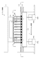
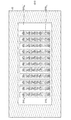
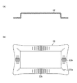
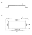
図1は、プレス機械10の要部と本発明に係るダイクッション装置のシム調整装置を含むダイクッション装置とを示す概略構成図である。また、図2は、図1の矢印2の方向から見たダイクッション装置100の要部平面図である。
[Schematic configuration of press machine and die cushion device]
FIG. 1 is a schematic configuration diagram showing a main part of a
図1及び図2において、11は、プレス機械10のスライドであり、12はプレス機械10のベッドである。
1 and 2, reference numeral 11 denotes a slide of the
スライド11は、プレス機械10のフレーム(図示せず)により鉛直方向に移動自在に案内されており、サーボモータやフライホイールによって回転駆動力が伝達されるクランク軸を含むクランク機構(図示せず)によって、図1上で上下方向に移動させられる。
The slide 11 is guided by a frame (not shown) of the
プレス機械10のベッド12上には、複数のダイクッションピン穴(以下、「C穴」という)を有するボルスタ13が配設されている。本例のボルスタ13には、格子状に配列された55(11×5)個のC穴が形成されている。
A bolster 13 having a plurality of die cushion pin holes (hereinafter referred to as “C holes”) is disposed on the
スライド11の下面には、上金型14が配設され、ボルスタ13の上面には、下金型15が配設される。本例の上金型14は、凹部を有するダイス型であり、下金型15は、上金型14の凹部に対応する凸部を有するパンチ型である。
An
上金型14と下金型15の間には、ブランクホルダ(皺押え板)16が配置され、ブランクホルダ16の下側が、ボルスタ13のC穴に挿通されている複数のダイクッションピン102により支持され、ブランクホルダ16の上側に材料20がセットされる(接触する)。
Between the
プレス機械10は、スライド11を下降させることにより、上金型14と下金型15との間で材料20をプレス成形する。また、ダイクッション装置100は、プレス成形中に材料20の周縁を下側から押圧するものである。
The
ダイクッションピン102の本数は、ボルスタ13に形成されたC穴の数と同数の55本設けられているが、55本のダイクッションピン102のうちのブランクホルダ16の投影面下に位置するダイクッションピン102が、ブランクホルダ16にダイクッション力を伝達するダイクッションピン102(以下、「使用ダイクッションピン」という)となる。また、55本のダイクッションピン102のうちの使用ダイクッションピン以外のダイクッションピンは、本例ではブランクホルダ16に挿入したままの状態になっているが、ブランクホルダ16にダイクッション力を伝達するダイクッションピン(皺押え)として機能しない。
The number of die cushion pins 102 is 55, which is the same as the number of C holes formed in the bolster 13. Of the 55 die cushion pins 102, a die located below the projection surface of the
ダイクッション装置100は、主としてクッションパッド110と、ダイクッション力を発生させるクッションパッド昇降機構として機能する左右2基の空気圧シリンダ120L,120Rと、シム厚発生装置として機能する複数の液圧シリンダ(油圧シリンダ)210を有するシム調整装置200(図3)とから構成されている。
The die cushion device 100 mainly includes a
クッションパッド110は、空気圧シリンダ120L,120Rによって支持され、空気圧シリンダ120L,120Rのクッション圧発生側加圧室120aには、図示しない公知の圧力制御回路が接続されている。
The
圧力制御回路は、ダイクッション作用時に空気圧シリンダ120L,120Rのクッション圧発生側加圧室120aに発生する圧力(クッション圧発生側加圧室120aに通じるエアタンクの圧力)を所望の圧力に調整することで、ダイクッション力を制御する。
The pressure control circuit adjusts the pressure generated in the cushion pressure generation
尚、ダイクッション力を発生させるクッションパッド昇降機構は、空気圧シリンダ120L,120Rを使用したものに限らず、油圧シリンダとこの油圧シリンダを駆動する油圧モータ及びサーボモータにより構成されたもの、クッションパッドを昇降させるスクリューナット機構と、このスクリューナット機構を駆動するサーボモータ、及び油圧ダンパを用いた機構等、種々のものが適用可能である。
The cushion pad raising / lowering mechanism for generating the die cushion force is not limited to the one using the
複数の油圧シリンダ210は、シム厚発生装置として機能するもので、クッションパッド110に配設されている。即ち、複数の油圧シリンダ210は、ボルスタ13に形成された複数のC穴に対向する位置(C穴の投影面下)に配設され、C穴に挿入されるダイクッションピン102の下端が、油圧シリンダ210のピストンロッドに当接するように配設されている。
The plurality of
図2には、クッションパッド110に格子状に配列された55(11×5)個の油圧シリンダ210(No.1からNo.55で示した55個の油圧シリンダ2101〜21055)が示されている。尚、図1には、55個の油圧シリンダ210のうちの一列の11個の油圧シリンダ210が示されており、11個の油圧シリンダ210、及び11個の油圧シリンダ210のピストンロッドに当接する11本のダイクッションピン102のうち、丸で囲んだ油圧シリンダ210及びダイクッションピン102が、それぞれシム厚調整に使用される油圧シリンダ210及び使用ダイクッションピン102である。
FIG. 2 shows 55 (11 × 5) hydraulic cylinders 210 (55
[ダイクッション装置のシム調整装置の第1の実施形態]
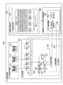
図3は、本発明に係るダイクッション装置のシム調整装置の第1の実施形態を示す要部ブロック図である。
[First embodiment of shim adjusting device of die cushion device]
FIG. 3 is a principal block diagram showing a first embodiment of a shim adjusting device for a die cushion device according to the present invention.
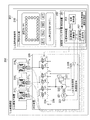
図3に示す第1の実施形態のシム調整装置200は、シム厚発生装置として機能する複数(55個)の油圧シリンダ210(2101、2102、…210N=55)と、液圧装置として機能する油圧装置220と、シム調整制御装置230とから構成されている。
The
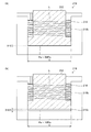
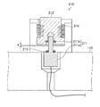
図4は、油圧シリンダ210の構成を示す縦断面図である。
FIG. 4 is a longitudinal sectional view showing the configuration of the
図4に示すように油圧シリンダ210は、ピストンロッド212が片ロッドの片ロッド式油圧シリンダ(片ロッド式液圧シリンダ)であり、ピストンロッド212を下降方向に付勢するバネ214を備えている。
As shown in FIG. 4, the
バネ214は、油圧シリンダ210の下降側加圧室210bに配設された皿バネであることが好ましい。皿バネは、市販の皿バネの組合せ(複数個の直列及び/又は並列の積み重ね)の方法により所望のバネ定数kに調整可能だからである。
The
各油圧シリンダ210の上昇側加圧室210aには、それぞれ油圧装置220から圧力制御された作動油(作動液)が供給できるようになっている。
Each of the
ここで、油圧シリンダ210のピストンロッド212の高さ方向位置は、油圧シリンダ210の上昇側加圧室210aに供給する作動油の圧力を制御することで、調整することができる。
Here, the height direction position of the
いま、バネ214のバネ定数、油圧シリンダの上昇側加圧室210aの断面積、油膜厚(シム厚)、油圧(圧力)、及びプリロードを、下記の記号で表すと、油膜厚Xは、[数1]式により表すことができる。
Now, when the spring constant of the
k:バネ定数[kN/mm]
S:油圧シリンダの上昇側加圧室210aの断面積[cm2]
X:油膜厚(シム厚)[mm]
Pa:油圧(MPa)
Fo:プリロード[kN]
[数1]
X=(Pa×S/10−Fo)/k
但し、[数1]式において、X<0の場合、X=0である。
k: Spring constant [kN / mm]
S: Cross-sectional area [cm 2 ] of ascending
X: Oil film thickness (shim thickness) [mm]
P a: hydraulic pressure (MPa)
F o : Preload [kN]
[Equation 1]
X = (P a × S / 10−F o ) / k
However, in the formula [1], when X <0, X = 0.
次に、油圧装置220について説明する。
Next, the
油圧装置220は、主として油圧源(液圧源)として機能するサーボモータ221により駆動される油圧ポンプ222と、サーボモータ221の角速度を検出するエンコーダ223と、油圧ポンプ222から作動油が供給される加圧ライン224と、タンク225に接続されたタンクライン226と、各油圧シリンダ210に対応して設けられた複数の第1の電磁弁VP(VP1、VP2、…、VPN=55)、及び複数の第2の電磁弁VT(VT1、VT2、…、VTN=55)と、リリーフ弁227と、加圧ライン224の圧力を検出する圧力検出器228とから構成されている。
The
複数の第1の電磁弁VPは、各油圧シリンダ210の上昇側加圧室210aと加圧ライン224とを接続するラインにそれぞれ配設され、また、複数の第2の電磁弁VTは、各油圧シリンダ210の上昇側加圧室210aとタンクライン226とを接続するラインにそれぞれ配設されている。
The plurality of first solenoid valves VP are respectively disposed on lines connecting the ascending
また、複数の第1の電磁弁VP及び複数の第2の電磁弁VTは、それぞれソレノイドが励磁(ON)されると開き、ソレノイドが消磁(OFF)されると閉じるノンリーク形電磁弁である。 The plurality of first solenoid valves VP and the plurality of second solenoid valves VT are non-leakage solenoid valves that open when the solenoid is energized (ON) and close when the solenoid is demagnetized (OFF).
複数の第1の電磁弁VP及び複数の第2の電磁弁VTは、通常OFFされているが、後述するシム調整制御装置230(油膜厚制御装置250)により複数の第1の電磁弁VP及び複数の第2の電磁弁VTのうちのいずれか1つの第1の電磁弁VP及び第2の電磁弁VTがON/OFFされる。そして、ON/OFF制御される第1の電磁弁VP及び第2の電磁弁に対応する1つの油圧シリンダ210が、複数の油圧シリンダ210のうちの調整対象の油圧シリンダ210となる(選択される)。
The plurality of first solenoid valves VP and the plurality of second solenoid valves VT are normally OFF, but the plurality of first solenoid valves VP and VP are controlled by a shim adjustment control device 230 (oil film thickness control device 250) described later. Any one of the plurality of second solenoid valves VT is turned ON / OFF. Then, one
油圧装置220は、選択された1つの調整対象の油圧シリンダ210の上昇側加圧室210aに所要の圧力の作動油を供給し、油圧シリンダ210のピストンロッド212の高さ方向位置(油膜厚)を調整する。
The
例えば、油圧シリンダ2101の油膜厚を調整する場合、油膜厚制御装置250からの第1の電磁弁VP及び第2の電磁弁VTへのON/OFF制御信号により、油圧シリンダ2101に対応する第2の電磁弁VT1のみがONにされ、他の第1の電磁弁VP及び第2の電磁弁VTがOFFにされる。この場合、油圧シリンダ2101の上昇側加圧室210a内の作動油は、バネ214によるプリロード(例えば、1kN)により第2の電磁弁VT1及びタンクライン226を介してタンク225に排出され、これにより油膜厚は0mmになる。
For example, when adjusting the oil film thickness of the
続いて、油膜厚制御装置250により第2の電磁弁VT1がOFFにされた後、第1の電磁弁VP1がONにされる。これにより、油圧ポンプ222から加圧ライン224及び第1の電磁弁VP1を介して油圧シリンダ2101のみに圧力制御された圧油を供給することができる。
Subsequently, after the second electromagnetic valve VT 1 is turned OFF by the oil
ここで、油圧シリンダ2101の上昇側加圧室210aに供給される作動油の油膜厚Xは、[数1]式に示したように油圧Paを制御することにより調整することができる。
Here, the oil film thickness X of the hydraulic fluid supplied to the raised
尚、圧力検出器228は、加圧ライン224の圧力を検出するもので、検出した圧力を示す圧力信号を、油圧Paを制御する際の圧力フィードバック信号として油膜厚制御装置250(圧力制御装置252の圧力制御演算器256)に出力する。また、エンコーダ223は、サーボモータ221の駆動軸の角速度を示す角速度信号を、油圧Paを制御する際の動的安定性を確保するための角速度フィードバック信号として、圧力制御演算器256に出力する。また、リリーフ弁227は、異常圧力発生時(突発的な異常圧力発生時)に動作し、油圧機器の破損を防止する手段として設けられている。
The
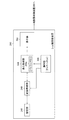
次に、シム調整制御装置230について説明する。
Next, the shim
シム調整制御装置230は、主としてシム厚設定装置240と、油膜厚制御装置250とから構成されている。
The shim
図5は、シム厚設定装置240の構成を示すブロック図である。
FIG. 5 is a block diagram showing the configuration of the shim
図5に示すようにシム厚設定装置240は、主としてタッチパネル付きの液晶表示器等の表示器242、第1の表示制御部及び第2の表示制御部として機能する表示制御部244、第1の操作部及び第2の操作部として機能する操作部246、記憶制御部248、及び記憶部249から構成されている。
As shown in FIG. 5, the shim
操作部246は、表示器242の表示画面上に設けられたタッチパネルの各種のアイコンボタン(図8に示した設定ボタン242c、確認ボタン242d、及び実行ボタン242e等)を含み、ユーザのタッチ操作による入力を受け付け、入力情報を表示制御部244に出力する。
The
ここで、操作部246により入力される入力情報は、複数のダイクッションピン102のうちの実際の皺押えに使用する使用ダイクッションピン102を選択する選択情報、選択した使用ダイクッションピン102毎の油膜厚(シム厚)を示すシム厚設定値、及びシム厚設定値を編集するための情報、プレス機械10にセットされた金型(上金型14、下金型15)を示す金型の識別情報(金型No.)等である。
Here, the input information input by the
表示制御部244は、操作部246から入力する各種の入力情報に基づいてその入力情報に対応する表示用画像を生成し、生成した表示用画像を表示器242に出力し、また、入力情報(ダイクッションピン毎の使用/未使用の選択情報、及び使用ダイクッションピン毎のシム厚設定値)をバッファメモリ244aに一時保持する。
The
表示器242には、表示制御部244から入力する表示用画像に基づいて、後述する図8から図11、図14及び図15等に示すように55(=11×5)本のダイクッションピン102の配置を示す配置図(ピン配置図)等を示す画面242aと、操作部246の一部として機能するアイコンボタンである選択ボタン242b、設定ボタン242c、確認ボタン242d、及び実行ボタン242eと、シム厚設定操作を支援するメッセージが表示される画面242fとが表示される。
The
シム厚設定装置240により設定され、バッファメモリ244aに一時保持されたダイクッションピン毎の使用/未使用の選択情報、及び使用ダイクッションピン毎のシム厚設定値は、油膜厚制御装置250に出力される。
The used / unused selection information for each die cushion pin set by the shim
このようにシム厚設定装置240は、ボルスタ13に形成された複数のC穴に挿入される複数のダイクッションピン102のうちの使用ダイクッションピンを選択するダイクッションピン選択器としての機能と、ダイクッションピン選択器により選択された複数の使用ダイクッションピンに対応する複数のシム厚設定値であって、使用ダイクッションピン毎にそれぞれ任意のシム厚設定値を設定するシム厚設定器としての機能を備えている。
As described above, the shim
また、記憶部249は、プレス機械10に使用される金型(金型No.)に関連付けて少なくとも使用ダイクッションピン毎のシム厚設定値を記憶するもので、本例では、図17に示すように金型No.毎にボルスタ13に形成された複数のC穴(C1〜C55:C穴の識別情報)に挿入される複数のダイクッションピンのうちのシム調整に使用する使用ダイクッションピン(使用“1”)、使用しない未使用ダイクッションピン(未使用“0”)を示す情報(即ち、ダイクッションピン毎の使用/未使用の選択情報)と、図18に示すように金型No.毎にボルスタ13に形成された複数のC穴(C1〜C55)に挿入される複数のダイクッションピン毎のシム厚設定値と、を記憶している。
The
シム厚設定装置240により適宜設定された少なくとも使用ダイクッションピン毎のシム厚設定値により使用ダイクッションピン毎に油膜厚(シム厚)が調整され、その後、試し打ち(成形トライ)による成形品の成形結果を参考にして、使用ダイクッションピン毎のシム厚設定値が再設定(修正)される。そして、記憶制御部248は、記憶操作部として機能する操作部246から記憶指示を入力すると、良品が成形されたときに使用された使用ダイクッションピン毎のシム厚設定値をバッファメモリ244aから取得し、成形トライした金型に関連付けて記憶部249に記憶させる。
The oil film thickness (shim thickness) is adjusted for each used die cushion pin by at least the shim thickness setting value for each used die cushion pin that is appropriately set by the shim
一方、プレス機械10にセットされた金型(金型No.)に対応する使用ダイクッションピン毎のシム厚設定値が、記憶部249に記憶されている場合、記憶制御部248は、記憶操作部として機能する操作部246から読出指示を入力すると、記憶部249からプレス機械10にセットされた金型に関連付けて記憶された使用ダイクッションピン毎のシム厚設定値を読み出し、表示制御部244に出力する(バッファメモリ244aに一時記憶させる)。
On the other hand, when the shim thickness setting value for each used die cushion pin corresponding to the die (die number) set in the
これにより、シム調整装置200によりシム調整の実績がある金型がプレス機械10にセットされた場合、自動的にシム調整を行うことができる。また、プレス機械10の金型の交換は、自動金型交換装置により行うことができるが、自動金型交換装置の自動金型交換シーケンス制御の一環として、自動金型交換時の金型搬入時(後)に、金型の金型No.を取得することで、自動金型交換シーケンス制御の一環として、自動金型交換時の金型搬入時(後)に、交換後の金型に対して自動的にシム調整を行うことができる。
Thereby, when the metal mold | die with the track record of shim adjustment with the
尚、記憶部249は、100型〜400型分の金型に対応するシム厚設定値を記憶することが可能である。また、記憶部249は、シム調整装置200(シム厚設定装置240)内に設けられたものに限らず、例えばプレス機械10やダイクッション装置100のPLC(Programmable Logic Controller)内に設けられた記憶部(データバンク)を使用することができる。
The
図3に戻って、油膜厚制御装置250は、各油圧シリンダ210の上昇側加圧室210aの圧力を制御することにより油膜厚(シム厚)を制御するもので、圧力制御装置252を含んで構成されている。
Returning to FIG. 3, the oil film
油膜厚制御装置250は、前述したようにシム厚設定装置240からダイクッションピン毎の使用/未使用の選択情報、及び使用ダイクッションピン毎のシム厚設定値を入力し、これらの入力情報に基づいて全てのダイクッションピン102を対象に、1つずつ順番に油膜厚の調整(シム調整)を行う。前述したように油膜厚制御装置250は、第1の電磁弁VP及び第2の電磁弁VTのON/OFFを制御することにより、調整対象の1つのダイクッションピン102に対応する油圧シリンダ210の上昇側加圧室210a内の作動油の油膜厚Xの調整を可能にし、調整しようとする油膜厚X(即ち、シム厚設定値)から、[数1]式に基づいて油膜厚Xに対応する圧力指令を演算する。
As described above, the oil film
圧力制御装置252は、圧力指令器254と圧力制御演算器256とから構成されている。圧力指令器254には、油膜厚制御装置250により調整対象のダイクッションピン毎に演算された圧力指令がセットされ、圧力指令器254は、セットされた圧力指令を圧力制御演算器256に出力する。
The
圧力制御演算器256の他の入力には、圧力検出器228により検出された加圧ライン224の圧力を示す圧力信号と、エンコーダ223により検出されたサーボモータ221の駆動軸の角速度を示す角速度信号とが加えられており、圧力制御演算器256は、圧力指令器254から入力する圧力指令と、圧力検出器228から入力する圧力信号とに基づいて、サーボモータ221のトルクを制御するためのトルク指令信号を演算する。この演算したトルク指令信号をサーボアンプ229を介してサーボモータ221に出力し、サーボモータ221により駆動される油圧ポンプ222から吐出される作動油の圧力(即ち、圧力検出器228により検出される圧力)が、圧力指令に対応する圧力になるようにサーボモータ221の駆動トルクを制御する。尚、サーボモータ221の駆動軸の角速度をそれぞれ検出するエンコーダ223から入力する角速度信号は、作動油の圧力を安定に制御するための補償に用いられる。
The other inputs of the
上記のように圧力制御装置252により油圧ポンプ222から吐出される作動油の圧力が制御されると、油圧ポンプ222から加圧ライン224及び第1の電磁弁VPを介して調整対象の油圧シリンダ210の上昇側加圧室210aに供給される作動油の油圧Paが、圧力指令に対応する圧力になり、油圧シリンダの上昇側加圧室210aの油膜厚X(シム厚)がシム厚設定値に調整される。
When the pressure of the hydraulic oil discharged from the
調整対象の油圧シリンダ210の油膜厚制御が終了すると、調整対象の油圧シリンダ210に対応する第1の電磁弁VPはOFFにされ、油圧シリンダ210のピストンロッド212の高さ方向位置(油膜厚)が保持される。
When the oil film thickness control of the
調整対象の油圧シリンダ210を順次切り換えて、上記の油膜厚制御を行うことにより、油膜厚の調整(シム調整)が行われる。
Oil film thickness adjustment (shim adjustment) is performed by sequentially switching the
[シム調整]
次に、上記構成のシム調整装置200を使用したシム調整について説明する。
[Shim adjustment]
Next, shim adjustment using the
本例で使用する金型(図1に示した上金型14、下金型15)は、横方向に長い材料(ブランク)20から断面が長方形状の角筒製品を絞り成形するものである。尚、本例では、初めて使用する金型の初期設定時を想定している。
The molds used in this example (
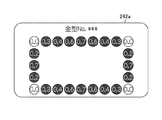
図6は、図1に示した矢印6の方向から見たダイクッション装置100の要部平面図である。
FIG. 6 is a plan view of the main part of the die cushion device 100 as seen from the direction of the
図6において、ボルスタ13には、No.1〜No.55で示した55箇所にC穴が形成されており、各C穴にはダイクッションピン(合計55本のダイクッションピン)が使用可能に挿入されている。 In FIG. 6, the bolster 13 has C holes formed at 55 locations indicated by No. 1 to No. 55, and die cushion pins (a total of 55 die cushion pins) can be used for each C hole. Has been inserted.
本金型を使用する場合、55本のダイクッションピンのうちの、No.2〜No.10、No.13、No.21、No.24、No.32、No.35、No43、No.46〜No.54の、ブランクホルダ16を押す(皺抑えとして機能する)部分に位置する、グレーで塗りつぶした二点鎖線の円で示した計24本のダイクッションピンが、ブランクホルダ16にダイクッション力を伝達する使用ダイクッションピンであり、実線の円で示したダイクッション及び白抜きの二点鎖線の円で示した他のダイクッションピンは、ブランクホルダ16に挿入されたままの状態であるが、皺抑えとして機能しない。
When using this mold, out of 55 die cushion pins, No.2 to No.10, No.13, No.21, No.24, No.32, No.35, No43, No. A total of 24 die-cushion pins, indicated by a two-dot chain line circled in gray, located in the
図7(A)及び(B)は、シム調整装置200を機能させなかった場合の成形品22の断面図及び平面図である。
7A and 7B are a sectional view and a plan view of the molded
シム調整装置200を機能させなかった場合、図13(A)に示すように油圧シリンダ210の上昇側加圧室には、油圧が作用しておらず、ピストンロッド212はバネ214に押されて最下限に位置する。従って、各油圧シリンダ210は、油膜厚が形成されていない状態(油膜厚X=0の状態)になっている。
When the
シム調整装置200を機能させなかった場合(あるいは、シム調整装置200がダイクッション装置に未装着な場合で、かつ各ダイクッションピンのシム調整を行わなかった場合)は、このような角筒絞りにおいて、作用させたダイクッション力は、基本的に各ダイクッションピン間で均一に(分散)作用する。その結果、基本的に(そもそも)材料が流動し難い成形品22の角部は、より強く皺抑え機能が作用し、亀裂22aが生じ(易くな)る。基本的に(そもそも)材料が流動し易い前後及び(特に距離が長い)左右の成形品22の角部間の中央部は、より弱く皺抑え機能が作用し、絞り皺22bが生じ(易くな)る。
When the
そこで、シム調整装置200を機能させ、各油圧シリンダ210の油膜厚を個別に制御し、シム調整を行う。
Therefore, the
図8から図11は、それぞれシム厚設定装置240を示す図であり、特にシム厚設定時のシム厚設定装置240(表示器242)の画面(操作画面等)の遷移図である。
FIGS. 8 to 11 are diagrams showing the shim
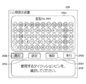
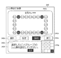
図8は、55本のダイクッションピンのうちの実際の皺押えに使用する使用ダイクッションピンを選択するときの操作画面を示している。図8に示すように、シム厚設定装置240の画面242aには、55本のダイクッションピンの配置を示すピン配置図(第1の配置図)、金型No.等が表示され、シム厚設定装置240の画面242fには、「使用するダイクッションピンを選択してください。」というメッセージが表示される。
FIG. 8 shows an operation screen when selecting a die cushion pin to be used for actual heel presser among 55 die cushion pins. As shown in FIG. 8, on the
ユーザは、シム厚設定装置240の操作画面で、ダイクッションピンを選択する操作を受け付ける選択ボタン242bを押し(タッチし)、続いて画面242aに表示されている55本のダイクッションピンの第1の配置図のうちから、使用ダイクッションピンの位置番号をタッチし、使用ダイクッションピンを選択する。尚、画面242aに表示された第1の配置図のうち、タッチにより選択された使用ダイクッションピンの配置を示すピン配置図(第2の配置図)は、未使用のダイクッションピンを含む第1の配置図とは識別可能に表示される。
On the operation screen of the shim
図9は、選択した使用ダイクッションピンに対してシム厚を設定する操作画面を示している。図9に示すように、シム厚設定装置240の画面242aには、選択した24本の使用ダイクッションピンの第2の配置図が表示され、シム厚設定装置240の画面242fには、「No.35=「 」のシム厚を設定してください。」というメッセージと、テンキー242gが表示される。
FIG. 9 shows an operation screen for setting the shim thickness for the selected use die cushion pin. As shown in FIG. 9, the
ユーザは、シム厚設定装置240の操作画面で、シム厚を設定するための設定ボタン242cを押し、選択した使用ダイクッションピンに対して、順次(ダイクッションピン位置番号順に)シム厚をテンキー242gにより入力(設定)する。
The user presses the
本例では、4個所の角部のダイクッションピン位置のシム厚設定値を0mm、その他のシム厚設定値を0.5mmに設定する。 In this example, the shim thickness setting values at the die cushion pin positions at the four corners are set to 0 mm, and the other shim thickness setting values are set to 0.5 mm.
尚、図9では、24本の使用ダイクッションピンのうちの13本の使用ダイクッションピンのシム厚の設定が完了した状態に関して示している。また、同じシム厚を設定する場合、纏まったクッションピン位置番号範囲を指定し、纏めて(一斉に)シム厚を設定することもできる。 FIG. 9 shows a state in which the shim thickness setting of 13 used die cushion pins out of 24 used die cushion pins is completed. Further, when setting the same shim thickness, it is also possible to specify a collective cushion pin position number range and collectively (simultaneously) set the shim thickness.
図10は、選択した使用ダイクッションピン全てにおける、シム厚設定値の確認及び部分的なダイクッションピンのシム厚設定値の変更を行う操作画面を示している。 FIG. 10 shows an operation screen for confirming the shim thickness setting value and changing the partial shim thickness setting value of the die cushion pin in all selected use die cushion pins.
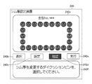
図10に示すように、シム厚設定装置240の画面242aには、24本の使用ダイクッションピンのピン配置図が表示され、かつ各ダイクッションピンのピン表示部にシム厚設定値が表示されている。また、シム厚設定装置240の画面242fには、「シム厚を変更するダイクッションピンを選択してください。」というメッセージが表示される。
As shown in FIG. 10, on the
ユーザは、シム厚設定装置240の操作画面で、シム厚設定値を確認する確認ボタン242dを押し、選択した使用ダイクッションピン全てに対して、設定したシム厚設定値を一覧表示させる。
The user presses a
そして、設定したシム厚設定値を部分的に変更する場合、ユーザは、操作画面上で変更したいピン表示部をタッチし、シム厚設定値を再入力することで変更させる。本例では、確認ボタン242dが、シム厚設定値を変更させる変更ボタンを兼ねているため、変更ボタンが設けられていないが、別途、変更ボタンを設けるようにしてもよい。
And when changing the set shim thickness setting value partially, a user touches the pin display part to change on an operation screen, and makes it change by re-inputting a shim thickness setting value. In this example, the
図11は、選択した使用ダイクッションピンに対するシム厚設定の実行時の操作画面を示している。 FIG. 11 shows an operation screen when executing shim thickness setting for the selected used die cushion pin.
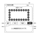
ユーザは、シム厚設定装置240の操作画面で、シム調整の実行ボタン242eを押し、選択した使用ダイクッションピン全てに対して、設定したシム厚設定値に基づくシム厚調整を実行させる。
The user presses a shim
この場合、シム厚設定装置240の画面242fには、「シム厚調整を実行中です。」というメッセージが表示される。また、シム厚設定装置240は、ダイクッションピン毎の使用/未使用の選択情報、及び設定した使用ダイクッションピン毎のシム厚設定値を、油膜厚制御装置250に出力する。
In this case, a message “Sim thickness adjustment is in progress” is displayed on the
本例のシム厚設定装置240によれば、シム厚設定装置240の操作画面を見ながら、対話式で操作部246を操作(タッチパネルをタッチ)して、使用ダイクッションピン毎のシム厚設定値を設定することができる。
According to the shim
油膜厚制御装置250は、シム厚設定装置240により設定された使用ダイクッションピン毎のシム厚設定値に基づいて、前述したように全てのダイクッションピン102を対象に、1つずつ順番に油膜厚の調整(シム調整)を行う。
Based on the shim thickness setting value for each used die cushion pin set by the shim
本例の油圧シリンダ210の下降側加圧室に配設されるバネ214は、複数の皿バネを組み合わせて(比較的弱い)バネ定数k(=3.66[kN/mm])を有し、また、油圧シリンダ210の上昇側加圧室210aの断面積Sは、28.27[cm2]である。
The
図13(A)に示すように、油圧シリンダ210の上昇側加圧室210aの油膜厚Xが0mmの場合、バネ214を約0.27mm圧縮させることで、1kNのプリロードを作用させ、安定したシム厚量“0”を確保している。尚、この時の油圧Paは、タンクライン226を介してタンク225に開放されたときの圧力であり、0Pa(大気圧)になっている。
As shown in FIG. 13 (A), when the oil film thickness X of the ascending
一方、図13(B)に示すように、シム厚設定値(油膜厚X)が0.5mmの場合、ダイクッション作用前に油圧シリンダ210の上昇側加圧室210aに作用させる油圧Paは、1MPaである。この油圧Pa(=1MPa)は、[数1]式に油膜厚X(=0.5mm)、断面積S(=28.27cm2)、プリロードFo(=1kN)、及びバネ定数k(=3.66[kN/mm])を代入することにより算出することができる。
On the other hand, as shown in FIG. 13 (B), when the shim thickness setting value (oil film thickness X) is 0.5 mm, the hydraulic pressure P a to be applied to the raised
そして、油膜厚制御装置250及び油圧装置220により、油圧シリンダ210の上昇側加圧室210aの油圧が1MPaになるように制御すると、油圧シリンダ210のピストンロッド212は、プリロードを相殺した上で、更にバネ214を0.5mm圧縮する位置(即ち、1MPaの油圧によりピストンロッド212を上昇させる力と、ピストンロッド212の上昇に伴って圧縮されたバネ214による付勢力とが釣り合う位置)まで上昇して停止する。
Then, when the oil film
ここで、バネ214を比較的弱く構成している理由は、油圧シリンダ210の上昇側加圧室210aに作用させる作動油の圧力に対して、上昇側加圧室210aに発生する油膜厚の調整の感度を高める為である。
Here, the reason why the
油圧シリンダ210の上昇側加圧室210aに作用する作動油の圧力P[MPa]に対する、ピストンロッド212の高さ位置の変位量X[mm]により、次式に示す変位定数KP/Xを定義すると、変位定数KP/Xは、KP/X=0.3[MPa/mm]〜30[MPa/mm]の範囲内であることが好ましい。
[数2]
KP/X=10×k/S
本例では、変位定数KP/Xは、[数1]より、バネ定数k(3.66[kN/mm])を油圧シリンダの上昇側加圧室断面積S(28.27[mm])で除した値に、単位合わせの10を乗じた値で約1.295[MPa/mm]である。
The displacement constant K P / X shown in the following equation is obtained by the displacement amount X [mm] of the height position of the
[Equation 2]
K P / X = 10 × k / S
In this example, the displacement constant K P / X is obtained by dividing the spring constant k (3.66 [kN / mm]) by the rising side cross-sectional area S (28.27 [mm]) of the hydraulic cylinder from [Equation 1]. The value obtained by multiplying the unit alignment by 10 is about 1.295 [MPa / mm].
上記のようにシム調整装置200を機能させ、全てのダイクッションピン102に対するシム調整が終了すると、ユーザは、プレス機械10を動作させ、初回の成形トライ(試し打ち)を行う。
When the
初回の成形トライ時には、図10等に示したように4個所の角部の使用ダイクッションピンのシム厚は0mmに調整され、他の使用ダイクッションピンのシム厚は0.5mmに調整されている。 At the first molding try, as shown in FIG. 10 and the like, the shim thickness of the used die cushion pins at the four corners is adjusted to 0 mm, and the shim thickness of the other used die cushion pins is adjusted to 0.5 mm. .
図12(A)及び(B)は、シム調整装置200を機能させた初回の成形トライによる成形品24の断面図及び平面図である。
FIGS. 12A and 12B are a cross-sectional view and a plan view of a molded
図12(B)に示すように成形品24の形状は、シム調整装置200を機能させなかった場合の成形品22(図7)の形状と未だ類似傾向を示しているが、材料が流動し難い成形品24の角部の亀裂24aの寸法は縮小し、材料が流動し易い前後及び(特に距離が長い)左右の成形品24の角部間の中央部の絞り皺24bは減少した。
As shown in FIG. 12 (B), the shape of the molded
<シム厚発生装置のシム厚維持性能の証明>
次に、シム厚発生装置として機能する油圧シリンダ210の、ダイクッション作用時のシム厚維持性能について説明する。
<Proof of shim thickness maintenance performance of shim thickness generator>
Next, the shim thickness maintenance performance at the time of the die cushion action of the
本例では、ダイクッション作用時のダイクッション力は、1200kN作用している。使用ダイクッションピン102は24本であるから、ダイクッションピン1本当りに約50kN作用する。尚、シム厚が0.5mmに調整された20本のダイクッションピンには、シム厚が0mmに調整された4本のダイクッションピンに比べて大きなダイクッション力が作用するが、以下、説明を簡単にするため、シム厚が0.5mmに調整されたダイクッションピン1本当りに50kNが作用しているものとする。 In this example, the die cushion force during the die cushion action is 1200 kN. Since there are 24 die cushion pins 102 used, about 50 kN acts per die cushion pin. The 20 die cushion pins whose shim thickness is adjusted to 0.5 mm have a larger die cushion force than the 4 die cushion pins whose shim thickness is adjusted to 0 mm. For simplicity, it is assumed that 50 kN is acting per die cushion pin whose shim thickness is adjusted to 0.5 mm.
したがって、プレス成形時に油圧シリンダ210の上昇側加圧室210aに発生する圧力をPa’とすると、圧力Pa’は、17.69MPa(=(50/28.7)×10)になる。
Therefore, when the pressure generated in the
一方、前述したようにシム厚を0.5mmに調整した油圧シリンダ210には、予めシム厚に相当する油圧(本例では、1MPa)が作用している為、プレス成形前後の油圧シリンダ210の上昇側加圧室210aの圧力変化をΔPaとすると、圧力変化ΔPaは、ΔPa=Pa’−Pa=17.69−1=16.69MPaになる。
On the other hand, as described above, the
この時、油膜厚(シム厚)に比例する油圧シリンダ210の上昇側加圧室210aの容積は、圧力変化ΔPa(増圧)分だけ圧縮されて収縮する。ここで、作動油の体積弾性係数Kを1200(MPa)、収縮量をΔX[mm]とすると、次式に示すように収縮量ΔXは、約0.007mmとなる。
At this time, the volume of the ascending
[数3]
ΔX=(ΔPa/K)×X=(16.69/1200)×0.5≒0.007[mm]
結局、成形中(収縮後)の油膜厚(シム厚)は、0.493(=0.5-0.007)mmとなり、殆ど当初設定した0.5mmが維持される。
[Equation 3]
ΔX = (ΔP a /K)×X=(16.69/1200)×0.5≈0.007 [mm]
Eventually, the oil film thickness (shim thickness) during molding (after shrinkage) is 0.493 (= 0.5-0.007) mm, and the initially set 0.5 mm is maintained.
さて、図12に示した初回の成形トライによる成形品24の結果から、成形品を更に良くする(成形品の亀裂と絞り皺を抑制する)為に、初回の成形トライ時に設定されたシム厚設定値を部分的に変更(修正)する。
Now, from the result of the molded
図14は、シム厚設定装置240の操作画面を示す図であり、特にシム厚設定値の変更状態を示している。
FIG. 14 is a diagram showing an operation screen of the shim
ユーザは、シム厚設定装置240の操作画面で、シム厚設定値を確認する確認ボタン242dを押し、選択した使用ダイクッションピン全てに対して、現在設定したシム厚設定値を一覧表示させる。
The user presses a
続いて、ユーザは、24本の使用ダイクッションピンのうちのシム厚を変更する使用ダイクッションピンのピン表示部を(同じシム厚に変更する分を纏めて)タッチする。図14に示すシム厚設定装置240の画面242aでは、タッチされた4箇所の使用ダイクッションピンのピン表示部が、他の使用ダイクッションピンのピン表示部と識別可能に表示されている。また、シム厚設定装置240の画面242fには、「選択したピン(グループ)のシム厚を設定してください。」というメッセージと、テンキー242gとが表示される。
Subsequently, the user touches the pin display portion of the used die cushion pin that changes the shim thickness among the 24 used die cushion pins (collectively changing the shim thickness). On the
ユーザは、タッチしたピン表示部に対応する使用ダイクッションピンのシム厚設定値を変更すべく、テンキー242gによりシム厚設定値を再入力する。本例では、図12(B)に示すように初回の成形トライ時に、成形品24の角部に亀裂24aを生じた為、角部の近傍のシム厚設定値を0.5mmから0.3mmに変更する。これは、角部近傍の皺抑え力(圧)をより低下させ、亀裂が発生しないようにするためである。
The user re-enters the shim thickness setting value with the
図15は、2回目のシム厚調整後のシム厚設定値の確認画面を示している。最終的に、シム厚設定装置240の画面242aに示すように、初回のシム厚設定値に対して、成形品の4つの角部近傍のシム厚設定値を亀裂防止の為に低下させ、左右前後の角部間の中央部の絞り皺を抑制する為に(連続的に)増加させる。
FIG. 15 shows a confirmation screen for the shim thickness setting value after the second shim thickness adjustment. Finally, as shown in the
そして、1回目のシム調整と同様に、ユーザは、実行ボタン242eを押すことにより、2回目のシム調整を実行させる。この場合、シム調整装置200は、シム厚設定値を変更した使用ダイクッションピンに対するシム調整のみを行うことが好ましい。
Similarly to the first shim adjustment, the user presses the
シム調整装置200により2回目のシム調整が終了すると、ユーザは、プレス機械10を動作させ、2回目の成形トライを行う。
When the second shim adjustment is completed by the
図16(A)及び(B)は、シム調整装置200を機能させた2回目の成形トライによる成形品26の断面図及び平面図である。
FIGS. 16A and 16B are a cross-sectional view and a plan view of a molded
図16(B)に示す成形品26は、シム調整が適正に行われた結果、成形品の角部の亀裂が消滅し、かつ前後左右の成形品の角部間の中央部の絞り皺が消滅した良品となる。
In the molded
このようにして、良品が成形された場合、ユーザは、記憶操作部として機能する操作部246を操作し、良品が成形されたときにシム厚設定装置240により設定されたダイクッションピン毎の使用/未使用の選択情報、及びダイクッションピン毎のシム厚設定値を、金型(金型No.)に関連付けて記憶部249に記憶させる記憶指示を、操作部246から記憶制御部248に出力させる。
In this way, when a non-defective product is molded, the user operates the
記憶制御部248は、操作部246から記憶指示を入力すると、バッファメモリ244aに保持されているダイクッションピン毎の使用/未使用の選択情報、及びダイクッションピン毎のシム厚設定値をバッファメモリ244aから取得し、成形トライした金型No.に関連付けて記憶部249に記憶させる。
When the
図17及び図18は、それぞれ金型No.に関連付けて記憶部249に記憶されたダイクッションピン毎の使用/未使用の選択情報、及びシム厚設定値を示す図表である。
FIGS. 17 and 18 are charts showing used / unused selection information and shim thickness setting values for each die cushion pin stored in the
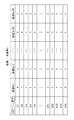
図17に示したダイクッションピン毎の使用/未使用の選択情報は、金型毎、かつ55本のダイクッションピンが挿入されるボルスタ13に形成されたC穴の位置情報(C1〜C55)に対応する情報であって、55本のダイクッションピンのうちの実際の皺押えに使用する使用ダイクッションピンを“1”、皺押えに使用しない未使用ダイクッションピンを“0”とする情報である。 The used / unused selection information for each die cushion pin shown in FIG. 17 is the position information (C1 to C55) of the C hole formed in the bolster 13 into which 55 die cushion pins are inserted for each die. Of the 55 die cushion pins, the used die cushion pin that is used for the actual heel presser is “1”, and the unused die cushion pin that is not used for the heel presser is “0”. It is.
このダイクッションピン毎の使用/未使用の選択情報によれば、全てのダイクッションピンについて、各ダイクッションピンが使用ダイクッションピンか、又は未使用ダイクッションピンかを判別することができる。尚、未使用ダイクッションピンについては、シム調整は不要(シム厚=0)とすることができる。 According to the used / unused selection information for each die cushion pin, it is possible to determine whether each die cushion pin is a used die cushion pin or an unused die cushion pin for all die cushion pins. It should be noted that shim adjustment is not necessary for the unused die cushion pin (shim thickness = 0).
図18に示したダイクッションピン毎のシム厚設定値は、金型毎、かつ55本のダイクッションピンが挿入されるボルスタ13に形成されたC穴の位置情報(C1〜C55)に対応する情報であって、各ダイクッションピンに対して設定されるダイクッションピン毎のシム厚設定値である。 The shim thickness setting value for each die cushion pin shown in FIG. 18 corresponds to position information (C1 to C55) of the C hole formed in the bolster 13 into which each die die and 55 die cushion pins are inserted. It is information and is a shim thickness setting value for each die cushion pin set for each die cushion pin.
尚、図18に示す例では、全てのダイクッションピンに対してシム厚設定値(シム厚設定値=0を含む)が設定されているが、図17に示すようなダイクッションピン毎の使用/未使用の選択情報がある場合には、少なくても使用ダイクッションピンに対してシム厚設定値が設定されていればよい。 In the example shown in FIG. 18, shim thickness setting values (including shim thickness setting value = 0) are set for all the die cushion pins, but the use for each die cushion pin as shown in FIG. / If there is unused selection information, it is sufficient that a shim thickness setting value is set for at least the used die cushion pin.
また、図17及び図18には、55型の金型(金型No.1〜No.55)に対応するダイクッションピン毎の使用/未使用の選択情報、及びシム厚設定値が示されているが、記憶部249には数100型分の金型に対応するシム厚設定値を記憶することが可能である。
17 and 18 show used / unused selection information and shim thickness setting values for each die cushion pin corresponding to 55 molds (molds No. 1 to No. 55). However, the
このように金型に関連付けてシム厚設定値を記憶部249に記憶させるようにしたため、シム調整装置200によりシム調整の実績がある金型がプレス機械10にセットされた場合、シム調整装置200は、セットされた金型に関連付けて記憶されたシム厚設定値を記憶部249から読み出し、読み出したシム厚設定値に基づいてダイクッションピン毎にシム厚調整を行うことにより自動的にシム調整を行うことができる。
Since the shim thickness setting value is stored in the
[シム調整方法]
図19及び図20は、本発明に係るシム調整装置200を使用したシム調整方法の実施形態を示すフローチャートである。
[Shim adjustment method]
19 and 20 are flowcharts showing an embodiment of a shim adjustment method using the
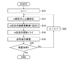
図19はシム調整方法の全体の流れを示すフローチャートである。 FIG. 19 is a flowchart showing the overall flow of the shim adjustment method.
図19において、mは、シム調整の回数を示すパラメータであり、初回のシム調整は、m=1である(ステップS10)。 In FIG. 19, m is a parameter indicating the number of times of shim adjustment, and m = 1 in the first shim adjustment (step S10).
ユーザは、シム調整装置200のシム厚設定装置240を操作し、m回目(初回はm=1)のシム厚の設定を行う(ステップS12)。
The user operates the shim
m回目のシム厚設定が行われると、油膜厚制御装置250は、シム厚設定されたダイクッションピン毎のシム厚設定値に基づいて各油圧シリンダ210の上昇側加圧室210aの油膜厚(シリンダ内圧)を制御する(ステップS14)。
When the mth shim thickness setting is performed, the oil
図20は、図19に示したステップS14の処理内容の一例を示すフローチャートであり、特にシム調整装置200の油膜厚制御装置250の動作を示すフローチャートである。
FIG. 20 is a flowchart showing an example of the processing content of step S14 shown in FIG. 19, and particularly a flowchart showing the operation of the oil film
図20において、パラメータnを、n=1にセットする(ステップS100)。ここで、パラメータnは、1番目から55番目の55本のダイクッションピンのうちのいずれか1つのダイクッションピンの位置番号を示し、n=1は、1番目のダイクッションピンを示す。 In FIG. 20, the parameter n is set to n = 1 (step S100). Here, the parameter n indicates the position number of any one of the 55 die cushion pins from the first to the 55th, and n = 1 indicates the first die cushion pin.
油膜厚制御装置250は、シム厚設定装置240から入力したダイクッションピン毎の使用/未使用の選択情報(図17参照)に基づいて、n番目のダイクッションピンは、皺押えに使用する使用ダイクッションピンか否かを判別する(ステップS102)。n番目のダイクッションピンが未使用ダイクッションピンと判別されると(「No」の場合)、ステップS104に遷移させる。
The oil film
ステップS104では、n番目のダイクッションピン102nの高さ方向位置を制御する油圧シリンダ210nに対応して設けられた第2の電磁弁VTnをON/OFF制御する。即ち、第2の電磁弁VTnをONにし、油圧シリンダ210nの上昇側加圧室210aの圧力を脱圧する。これにより、油圧シリンダ210nの上昇側加圧室210aの油膜厚は、0になる。脱圧後は第2の電磁弁VTnをOFFにし、OFF遅延タイマをカウントする(ステップS106)。OFF遅延タイマは、第2の電磁弁VTnで確実に脱圧するために用いられる。
In step S104, n-th
続いて、次の順番のダイクッションピンを調整対象とすべく、ダイクッションピンの位置番号を示すパラメータnを1だけインクリメントし(ステップS108)、ステップS102に遷移させる。 Subsequently, the parameter n indicating the position number of the die cushion pin is incremented by 1 (step S108) and the process proceeds to step S102 in order to set the die cushion pin in the next order as the adjustment target.
一方、ステップS102において、n番目のダイクッションピンが使用ダイクッションピンであると判別されると(「Yes」の場合)、ステップS110に遷移させる。尚、この場合のn番目のダイクッションピン102nに対向する油圧シリンダ210nは、調整対象の油圧シリンダ210となる。
On the other hand, if it is determined in step S102 that the nth die cushion pin is a used die cushion pin (in the case of “Yes”), the process proceeds to step S110. In this case, the
ステップS110では、シム厚設定装置240から入力したダイクッションピン毎のシム厚設定値(図18参照)のうちから、n番目のダイクッションピン102nに対応して設定されたシム厚設定値MRnを取得し、取得したシム厚設定値MRnから圧力指令PRnを演算する。この圧力指令PRnは、前述した[数1]式において、油膜厚Xとしてシム厚設定値MRnを代入することにより算出することができる。
In step S110, the shim thickness setting value MRn set corresponding to the nth die cushion pin 102n from among the shim thickness setting values (see FIG. 18) for each die cushion pin input from the shim
次に、n番目のダイクッションピン102nの高さ方向位置を制御する油圧シリンダ210nに対応して設けられた第2の電磁弁VTnをON/OFF制御し(ステップS112)、油圧シリンダ210nの脱圧後に第2の電磁弁VTnをOFFにし、OFF遅延タイマをカウントする(ステップS114)。OFF遅延タイマは、第2の電磁弁VTnを確実にOFFさせてから次の処理(後述する第1の電磁弁VPnのON制御)に遷移させる。
Next, the second solenoid valve VTn provided corresponding to the
続いて、ステップS112及びS114により脱圧され、油膜厚が0とされた調整対象の油圧シリンダ210nに対応して設けられた第1の電磁弁VPnをONにし(ステップS116)、ON遅延タイマをカウントする(ステップS118)。ON遅延タイマは、第1の電磁弁VPnを確実にONさせてから次の処理(圧力制御)に遷移させるために用いられる。
Subsequently, depressurized by steps S112 and S114, the ON of the first solenoid valve VPn provided corresponding to the
ON遅延タイマの経過後、ステップS110で演算した圧力指令PRnを、圧力制御装置252の圧力指令器254にセットする(ステップS120)。
After elapse of the ON delay timer, the pressure command PRn calculated in step S110 is set in the
圧力制御装置252は、圧力指令器254にセットされた圧力指令PRnに基づいて油圧装置220を介して調整対象の油圧シリンダ210nの上昇側加圧室210aの圧力が、圧力指令PRnに対応する圧力になるように油圧装置220を制御し(ステップS122〜S130)、これにより調整対象の油圧シリンダ210nの上昇側加圧室210aの油膜厚を調整する。
In the
即ち、圧力制御装置252は、圧力指令器254にセットされた圧力指令PRnと圧力検出器228から入力する圧力信号とに基づいて、サーボモータ221のトルクを制御するためのトルク指令信号を演算し、演算したトルク指令信号をサーボアンプ229を介してサーボモータ221に出力し、圧力検出器228により検出された圧力が圧力指令PRnに対応した圧力に達すると(ステップS126)、ステップS116でONにした第1の電磁弁VPnをOFFにして調整対象の油圧シリンダ210nに対する圧力制御(油膜厚制御)を終了させる(ステップS130)。
That is, the
調整対象の油圧シリンダ210nに対する圧力制御が終了すると、パラメータnがN(=55)に達したか否か(即ち、55本の全てのダイクッションピンに対する圧力制御(脱圧制御を含む)が終了したか否か)を判別し(ステップS132)、n=Nの場合(「No」の場合)、ステップS108によりパラメータnを1だけインクリメントした後、ステップS102に遷移させる。
When the pressure control for the
一方、ステップS132において、n=Nと判別されると(「Yes」の場合)、全てのダイクッションピンに対する圧力制御(油膜厚制御)が終了したことになり、m回目の油膜厚制御を終了させる。 On the other hand, if it is determined in step S132 that n = N (in the case of “Yes”), pressure control (oil film thickness control) for all the die cushion pins is completed, and the m-th oil film thickness control is terminated. Let
図19に戻って、m回目の油膜厚制御が終了すると、ユーザは、プレス機械10を動作させ、m回目の成形トライ(m=1の場合は、初回の成形トライ)を行う(ステップS16)。
Returning to FIG. 19, when the m-th oil film thickness control is completed, the user operates the
ユーザは、m回目の成形トライによりプレス成形された成形品の検査を行う(ステップS18)。成形品の検査は、成形品のどの箇所にどの程度の亀裂が発生しているか、又は成形品のどの箇所にどの程度の絞り皺が発生しているか等を調べる検査である。 The user inspects the molded product press-molded by the m-th molding try (step S18). The inspection of the molded product is an inspection for checking how many cracks have occurred in which part of the molded product, how much squeezing has occurred in which part of the molded product, and the like.
ユーザは、成形品の成形結果(検査結果)により成形トライによりプレス成形された成形品が所望の品質の成形品か否かを判別し(ステップS20)、所望の品質の成形品ではない(検査不合格)と判別すると(「No」の場合)、mを1だけインクリメントし(ステップS22)、ステップS12に戻り、成形品の成形結果を参考にして、mがインクリメントされた「m回目のシム厚設定」等を行う。 The user discriminates whether or not the molded product press-molded by the molding trie is a molded product of a desired quality based on the molded result (inspection result) of the molded product (step S20), and is not a molded product of the desired quality (inspection). If “No” is determined (in the case of “No”), m is incremented by 1 (step S22), the process returns to step S12, and m is incremented with reference to the molding result of the molded product. Thickness setting "is performed.
このようにして、所望の品質の成形品がプレス成形されるまで、シム調整と成形トライとを繰り返し実行する。 In this manner, shim adjustment and molding try are repeatedly performed until a molded product of a desired quality is press-molded.
本発明によれば、一回一箇所に5分程度のシム調整作業時間を費やしていた従来の手動(手作業)によるシム調整を30秒程度に短縮することができ、トータルで半日要していた一連のシム調整作業を30分程度で完了させることができ、あるいはシム調整作業時間が短縮された分、成形性の確認やより微調整に時間を費やすこと(調整回数を増やすこと)が可能になり、製品精度を向上させることができる。 According to the present invention, the conventional manual (manual) shim adjustment, which took about 5 minutes of shim adjustment work time at one place, can be shortened to about 30 seconds, which takes a total of half a day. A series of shim adjustment operations can be completed in about 30 minutes, or it is possible to spend more time on confirmation of formability and fine adjustment (increase the number of adjustments) as the shim adjustment operation time is shortened. Thus, product accuracy can be improved.
また、シム厚は、従来は板(断片)材を用いることによる(例えば、0.2mm材で不足な場合は0.4mm材を用いる等)有段階調整式であるのに対して、シム調整装置200では無段階調整式になり、調整精度が向上する。
Further, the shim thickness is conventionally a step-adjustable type by using a plate (piece) material (for example, a 0.4 mm material is used when the 0.2 mm material is insufficient), whereas the
更に、シム調整装置200は、装置が単純(油圧装置220が単純、圧力検出器228も1個のみ使用)な為、安価に構成することができる。
Furthermore, since the
更にまた、従来の手動(手作業)によるシム調整は、設定したシム厚を確認することが困難である。例えば、シムが脱落した場合でも、手間をかけて確認しない限りそのことが分からない。作業者は、シムを装着したつもりで、その後の結果を評価しようとするが、実際にはシムが所定の位置に無いことが多々生じ得る。シム調整装置200によれば、このような問題は発生しない。
Furthermore, in the conventional manual (manual) shim adjustment, it is difficult to confirm the set shim thickness. For example, even if a shim falls off, it is not known unless it is confirmed with time and effort. The operator intends to wear the shim and tries to evaluate the subsequent results, but in actuality, the shim may often not be in place. According to the
[ダイクッション装置のシム調整装置の第2の実施形態]
図21は、本発明に係るダイクッション装置のシム調整装置の第2の実施形態を示す要部ブロック図である。尚、図3に示した第1の実施形態のシム調整装置200と共通する部分には同一の符号を付し、その詳細な説明は省略する。
[Second Embodiment of Shim Adjustment Device for Die Cushion Device]
FIG. 21 is a principal block diagram showing a second embodiment of a shim adjusting device for a die cushion device according to the present invention. In addition, the same code | symbol is attached | subjected to the part which is common in the
図21に示す第2の実施形態のシム調整装置200’は、シム厚発生装置として機能する複数(55個)の油圧シリンダ210’(2101’、2102’、…210N=55’)が、第1の実施形態に使用されている油圧シリンダ210と異なるとともに、油膜厚制御装置250’が異なる。
The
図22に示すように第2の実施形態のシム調整装置200’に使用される油圧シリンダ210’は、ピストンロッド212’の高さ方向位置を検出する位置検出器211を内蔵している点で、図4に示した第1の実施形態のシム調整装置200に使用される油圧シリンダ210と相違する。
As shown in FIG. 22, the
本例の位置検出器211は、油圧シリンダ210’のピストンロッド212’とシリンダ本体との相対的な変位を検出する磁歪式変位センサであり、センサロッド部を有するセンサ本体211aと、リング状の磁石211bとから構成される。
The
センサ本体211aは、油圧シリンダ本体の底部に配設され、ロッド部が油圧シリンダ本体内に挿入されている。油圧シリンダ本体とロッド部との間には、シール部材(Oリング)213が配設され、油圧シリンダ210’の作動油が漏れないようになっている。
The
磁石211bは、ロッド部が挿入される態様でピストンロッド212’の下部に形成された中空部に配置されている。
The
磁歪式変位センサである位置検出器211は、油圧シリンダ210’のピストンロッド212’の位置を検出するもので、センサ本体211aからロッド部の磁歪線に励起パルスを送出し、励起パルスに磁石211bの外部磁場が作用することによって発生する歪みパルス戻ってくるまでの時間に基づいてセンサ本体211aと磁石211bとの距離を算出する。即ち、位置検出器211は、油圧シリンダ210’の上昇側加圧室の油膜厚Xを検出する。
The
図21に戻って、55個の油圧シリンダ210’(2101’、2102’、…、210N’)に配設された55個の位置検出器211(2111’、2112’、…、211N’)によりそれぞれ検出された油圧シリンダ210’の上昇側加圧室の油膜厚Xを示す位置検出信号は、油膜厚制御装置250’の位置制御装置251(位置信号選択器257)に加えられる。
Returning to FIG. 21, 55 position detectors 211 (211 1 ′, 211 2 ′,...) Disposed in 55
第1の実施形態の油膜厚制御装置250が各油圧シリンダ210の上昇側加圧室210aの圧力を制御することにより、上昇側加圧室210aの油膜厚(シム厚)を制御するのに対し、第2の実施形態の油膜厚制御装置250’は、各油圧シリンダ210’のシリンダ位置(ピストンロッド位置)を制御することにより、上昇側加圧室の油膜厚(シム厚)を制御する点で、第1の実施形態の油膜厚制御装置250と相違する。
Whereas the oil film
したがって、第2の実施形態の油膜厚制御装置250’は、位置制御装置251を備えている。
Therefore, the oil film
位置制御装置251は、主として位置指令器253と、位置制御演算器255と、位置信号選択器257とから構成されている。
The position controller 251 mainly includes a
位置指令器253には、シム厚設定装置240から入力したダイクッションピン毎のシム厚設定値のうちの、調整対象のダイクッションピンに対応するシム厚設定値が、位置指令としてセットされ、位置指令器253は、セットされた位置指令を位置制御演算器255に出力する。
Of the shim thickness setting value for each die cushion pin input from the shim
位置制御演算器255の他の入力には、位置信号選択器257により選択された位置検出信号と、エンコーダ223により検出されたサーボモータ221の駆動軸の角速度を示す角速度信号とが加えられている。
As other inputs of the
位置信号選択器257は、55個の位置検出器211から入力する位置検出信号のうちの、調整対象のダイクッションピンに対向する油圧シリンダ210’に配設された位置検出器211から入力する位置検出信号を選択し、選択した位置検出信号を位置制御演算器255に出力する。
The
位置制御演算器255は、位置指令器253から入力する位置指令と、位置信号選択器257から入力する位置検出信号とに基づいて、サーボモータ221のトルクを制御するためのトルク指令信号を演算する。この演算したトルク指令信号をサーボアンプ229を介してサーボモータ221に出力し、サーボモータ221により駆動される油圧ポンプ222から吐出される作動油を制御することにより、調整対象の油圧シリンダ210’のピストンロッド212’の位置が、位置指令に対応する位置になるように位置制御する。尚、エンコーダ223から入力する角速度信号は、作動油を安定に制御するための補償に用いられる。
The
第2の実施形態のシム調整装置200’は、上記のようにして複数(55本)の油圧シリンダ210’の位置を1つずつ個別に制御することで、シム調整を行うため、圧力検出器は不要になるが、油圧シリンダ210’毎に位置検出器211を設ける必要がある。
Since the
また、第2の実施形態のシム調整装置200’は、調整対象であるシム厚(油膜厚)を直接制御する位置制御方式である点で、圧力制御方式の第1の実施形態のシム調整装置200と比較して油膜厚の制御精度が向上する。
Further, the
反面、位置検出器を多数要し、信号線数も増加し(これらは、可動させる必要があり)、位置制御装置251に入力するチャンネル数も増加する為、装置が複雑化し、コスト高を招く。 On the other hand, a large number of position detectors are required, the number of signal lines increases (they need to be moved), and the number of channels input to the position control device 251 also increases, which complicates the device and increases costs. .
[その他]
本実施形態では、クッションパッドに55個の油圧シリンダが設けられている場合について説明したが、油圧シリンダの個数はこの実施形態に限らない。
[Others]
In this embodiment, the case where 55 hydraulic cylinders are provided in the cushion pad has been described, but the number of hydraulic cylinders is not limited to this embodiment.
また、本実施形態では、シム調整装置の作動液として油を使用した場合について説明したが、これに限らず、水やその他の液体を使用してもよい。 Moreover, although this embodiment demonstrated the case where oil was used as a hydraulic fluid of a shim adjustment apparatus, not only this but water and another liquid may be used.
更に、本発明はダイクッション装置の構成には限定されず、あらゆる種類のダイクッション装置のシム調整装置として適用することができる。 Furthermore, this invention is not limited to the structure of a die cushion apparatus, It can apply as a shim adjustment apparatus of all kinds of die cushion apparatuses.
また、本発明は、上述した実施形態に限定されず、本発明の要旨を逸脱しない範囲において、各種の改良や変形を行ってもよいことは言うまでもない。 It goes without saying that the present invention is not limited to the above-described embodiments, and various improvements and modifications may be made without departing from the scope of the present invention.
10…プレス機械、11…スライド、12…ベッド、13…ボルスタ、14…上金型、15…下金型、16…ブランクホルダ、20…材料、22,24,26…成形品、100…ダイクッション装置、110…クッションパッド、120L,120R…空気圧シリンダ、200,200’…シム調整装置、210,2101〜210N,210’ ,2101’〜210N’…油圧シリンダ、211,2111〜211N…位置検出器、212…ピストンロッド、214…バネ、220…油圧装置、221…サーボモータ、222…油圧ポンプ、223…エンコーダ、224…加圧ライン、226…タンクライン、228…圧力検出器、230…シム調整制御装置、240…シム厚設定装置、242…表示器、244…表示制御部、246…操作部、248…記憶制御部、249…記憶部、250、250’…油膜厚制御装置、251…位置制御装置、252…圧力制御装置、253…位置指令器、254…圧力指令器、255…位置制御演算器、256…圧力制御演算器、257…位置信号選択器、VP,VP1〜VPN…第1の電磁弁、VT,VT1〜VTN…第2の電磁弁
DESCRIPTION OF
Claims (18)
前記クッションパッドに配設された複数の液圧シリンダであって、前記プレス機械のボルスタに形成された複数のダイクッションピン穴に対向する位置に配設され、前記ダイクッションピン穴に挿入されるダイクッションピンの下端が、ピストンロッドに当接する複数の液圧シリンダと、
前記複数の液圧シリンダの上昇側加圧室にそれぞれ独立して作動液を供給し、又は前記上昇側加圧室から作動液を排出させる液圧装置と、
前記複数のダイクッションピン穴に挿入される複数のダイクッションピンのうちの、前記ブランクホルダにダイクッション力を伝達する使用ダイクッションピンにそれぞれ対応する前記液圧シリンダの上昇側加圧室に、前記液圧装置からそれぞれ独立して作動液を供給させ、各液圧シリンダのピストンロッドの高さ方向位置をそれぞれ独立して調整するシム調整制御装置と、
を備えたダイクッション装置のシム調整装置。 In a die cushion device having a cushion pad that supports a blank holder via a plurality of die cushion pins, and a cushion pad lifting mechanism that supports the cushion pad and generates a die cushion force when the press machine slides down.
A plurality of hydraulic cylinders disposed on the cushion pad, disposed at positions facing a plurality of die cushion pin holes formed in the bolster of the press machine, and inserted into the die cushion pin holes. A plurality of hydraulic cylinders whose lower ends of the die cushion pins are in contact with the piston rod;
A hydraulic device that independently supplies hydraulic fluid to the rising side pressurization chambers of the plurality of hydraulic cylinders, or discharges the hydraulic fluid from the ascending side pressurization chambers;
Among the plurality of die cushion pins inserted into the plurality of die cushion pin holes, in the ascending side pressurizing chamber of the hydraulic cylinder respectively corresponding to the use die cushion pin that transmits the die cushion force to the blank holder, Shim adjustment control devices for independently supplying hydraulic fluid from the hydraulic devices and independently adjusting the height direction positions of the piston rods of the hydraulic cylinders;
Shim adjustment device for die cushion device comprising:
前記複数のダイクッションピン穴に挿入される複数のダイクッションピンのうちの使用ダイクッションピンを選択するダイクッションピン選択器と、前記ダイクッションピン選択器により選択された複数の使用ダイクッションピンに対応する複数のシム厚設定値であって、前記使用ダイクッションピン毎にそれぞれ任意のシム厚設定値を設定するシム厚設定器とからなるシム厚設定装置を備え、
前記シム厚設定装置により設定された前記使用ダイクッションピン毎のシム厚設定値に基づいて、前記複数の使用ダイクッションピンにそれぞれ対応する液圧シリンダの上昇側加圧室に、前記液圧装置からそれぞれ独立して作動液を供給させ、各液圧シリンダのピストンロッドの高さ方向位置をそれぞれ独立して調整する請求項1に記載のダイクッション装置のシム調整装置。 The shim adjustment control device
A die cushion pin selector for selecting a die cushion pin to be used among a plurality of die cushion pins to be inserted into the plurality of die cushion pin holes, and a plurality of die cushion pins selected by the die cushion pin selector. A plurality of corresponding shim thickness setting values, comprising a shim thickness setting device comprising a shim thickness setting device for setting an arbitrary shim thickness setting value for each of the used die cushion pins,
Based on the shim thickness setting value for each of the used die cushion pins set by the shim thickness setting device, the hydraulic device is provided in the ascending pressure chamber of the hydraulic cylinder corresponding to each of the plurality of used die cushion pins. The shim adjusting device for a die cushion device according to claim 1, wherein the hydraulic fluid is supplied independently from each other to adjust the position in the height direction of the piston rod of each hydraulic cylinder independently.
前記記憶操作部から前記記憶指示を入力すると、前記プレス機械に使用される金型に関連付けて、少なくとも前記シム厚設定装置により設定された前記使用ダイクッションピン毎のシム厚設定値を前記記憶部に記憶させ、前記記憶操作部から前記読出指示を入力すると、前記プレス機械に使用される金型に関連付けて記憶された前記使用ダイクッションピン毎のシム厚設定値を前記記憶部から読み出す記憶制御部と、
前記シム調整制御装置は、
前記記憶操作部での操作に基づいて前記記憶制御部により前記記憶部から前記プレス機械に使用される金型に関連付けて記憶された前記使用ダイクッションピン毎のシム厚設定値が読み出されると、前記読み出された前記使用ダイクッションピン毎のシム厚設定値に基づいて、前記複数の使用ダイクッションピンにそれぞれ対応する液圧シリンダの上昇側加圧室に、前記液圧装置からそれぞれ独立して作動液を供給させ、各液圧シリンダのピストンロッドの高さ方向位置をそれぞれ独立して調整する請求項2に記載のダイクッション装置のシム調整装置。 Outputs a storage instruction for storing at least a shim thickness setting value for each used die cushion pin in a storage unit in association with a mold used in the press machine, or in association with a mold used in the press machine A storage operation unit for outputting a readout instruction for reading a shim thickness setting value for each die cushion pin used from the storage unit;
When the storage instruction is input from the storage operation unit, at least the shim thickness setting value for each used die cushion pin set by the shim thickness setting device in association with the mold used in the press machine is stored in the storage unit. Storage control for reading out the shim thickness setting value for each of the used die cushion pins stored in association with the die used in the press machine when the reading instruction is input from the storage operation unit And
The shim adjustment control device
When the shim thickness setting value for each of the used die cushion pins stored in association with the mold used in the press machine is read from the storage unit by the storage control unit based on the operation in the storage operation unit, Based on the read shim thickness setting value for each of the used die cushion pins, the ascending pressure chambers of the hydraulic cylinders respectively corresponding to the plurality of used die cushion pins are independent of the hydraulic device. The shim adjustment device for a die cushion device according to claim 2, wherein hydraulic fluid is supplied to adjust the height direction position of the piston rod of each hydraulic cylinder independently.
前記シム調整制御装置は、前記液圧装置から前記液圧シリンダの上昇側加圧室に供給する作動液の圧力を制御することにより、該液圧シリンダのピストンロッドの高さ方向位置を調整する請求項5から8のいずれか1項に記載のダイクッション装置のシム調整装置。 The hydraulic cylinder includes a spring that urges the piston rod in a downward direction,
The shim adjustment control device adjusts the height direction position of the piston rod of the hydraulic cylinder by controlling the pressure of the hydraulic fluid supplied from the hydraulic device to the pressurizing chamber of the hydraulic cylinder. The shim adjustment apparatus of the die cushion apparatus of any one of Claim 5 to 8.
前記使用ダイクッションピン毎に設定されたシム設定値に基づいて演算された前記液圧シリンダの上昇側加圧室の圧力指令と、前記液圧シリンダの上昇側加圧室の圧力とに基づいて前記液圧装置から前記液圧シリンダの上昇側加圧室に供給する作動液を制御する請求項9から11のいずれか1項に記載のダイクッション装置のシム調整装置。 The shim adjustment control device
Based on the pressure command of the rising side pressurizing chamber of the hydraulic cylinder calculated based on the shim set value set for each of the used die cushion pins, and the pressure of the rising side pressurizing chamber of the hydraulic cylinder The shim adjustment device for a die cushion device according to any one of claims 9 to 11, wherein the hydraulic fluid supplied from the hydraulic device to the ascending pressure chamber of the hydraulic cylinder is controlled.
前記シム調整制御装置は、
前記使用ダイクッションピン毎に設定されたシム設定値に基づいて演算された前記液圧シリンダの上昇側加圧室の圧力指令と、前記圧力検出器により検出された圧力とに基づいて、前記液圧源から前記加圧ラインに供給される作動液の圧力を制御し、前記複数の第1の電磁弁のうちのON制御された第1の電磁弁に対応する前記液圧シリンダの上昇側加圧室の圧力を、前記圧力指令に対応する圧力にする請求項12に記載のダイクッション装置のシム調整装置。 A pressure detector for detecting the pressure generated in the pressure line;
The shim adjustment control device
Based on the pressure command of the ascending pressure chamber of the hydraulic cylinder calculated based on the shim set value set for each of the used die cushion pins, and the pressure detected by the pressure detector, the liquid The pressure of the hydraulic fluid supplied from the pressure source to the pressurization line is controlled, and the rising side addition of the hydraulic cylinder corresponding to the first solenoid valve that is ON-controlled among the plurality of first solenoid valves. The shim adjustment device for a die cushion device according to claim 12, wherein the pressure in the pressure chamber is set to a pressure corresponding to the pressure command.
前記シム調整制御装置は、シム厚設定値と前記位置検出器により検出された前記ピストンロッドの高さ方向位置とに基づいて前記液圧装置から前記液圧シリンダの上昇側加圧室に供給する作動液を制御する請求項1から8のいずれか1項に記載のダイクッション装置のシム調整装置。 A plurality of position detectors for respectively detecting height direction positions of piston rods of the plurality of hydraulic cylinders;
The shim adjustment control device supplies the pressure-side pressure chamber of the hydraulic cylinder from the hydraulic device based on the shim thickness setting value and the position in the height direction of the piston rod detected by the position detector. The shim adjustment device for a die cushion device according to any one of claims 1 to 8, which controls the hydraulic fluid.
前記第1の表示制御部は、前記第1の操作部からの操作入力に応じて前記第2の配置図を前記表示器の表示画面に表示させ、
前記ダイクッションピン選択器は、前記表示器の表示画面に表示された前記第2の配置図に基づいて前記使用ダイクッションピンを選択する請求項2又は3に記載のダイクッション装置のシム調整装置。 The die cushion pin selector includes a display and a plurality of die cushion pin holes inserted into the plurality of die cushion pin holes or the plurality of die cushion pin holes on at least a screen of the display. A first display control unit for displaying a layout diagram of 1 and a second layout diagram showing a layout of a die cushion pin hole into which the used die cushion pin is inserted or the used die cushion pin; A first operation unit for interactively editing the second layout map while viewing the first layout map and the second layout map displayed on the screen,
The first display control unit causes the second layout diagram to be displayed on the display screen of the display unit in response to an operation input from the first operation unit,
The shim adjustment device for a die cushion device according to claim 2 or 3, wherein the die cushion pin selector selects the used die cushion pin based on the second layout diagram displayed on a display screen of the display. .
前記第2の表示制御部は、前記第2の操作部からの操作入力に応じて編集された前記任意のシム厚設定値を前記表示器の表示画面に表示させ、
前記シム厚設定器は、前記表示器の画面上に表示される前記シム厚設定値を、前記使用ダイクッションピン毎のシム厚設定値として設定する請求項15に記載のダイクッション装置のシム調整装置。 The shim thickness setting device is configured to display a shim thickness setting value for each die cushion pin used in association with the display and the second layout diagram displayed on the display screen. And a shim thickness setting value for each die cushion pin used interactively while editing the shim thickness setting value displayed on the screen of the display unit and the display unit. 2 operation units,
The second display control unit displays the arbitrary shim thickness setting value edited in response to an operation input from the second operation unit on a display screen of the display unit,
16. The shim adjustment of the die cushion device according to claim 15, wherein the shim thickness setting device sets the shim thickness setting value displayed on the screen of the display as a shim thickness setting value for each of the used die cushion pins. apparatus.
前記複数のダイクッションピン穴に挿入される複数のダイクッションピンのうちの使用ダイクッションピンを選択する第1のステップと、
前記第1のステップにより選択された複数の使用ダイクッションピンに対応する複数のシム厚設定値であって、前記使用ダイクッションピン毎にそれぞれ任意のシム厚設定値を設定する第2のステップと、
前記第2のステップにより設定された前記使用ダイクッションピン毎のシム厚設定値に基づいて、前記複数の使用ダイクッションピンにそれぞれ対応する液圧シリンダの上昇側加圧室に、前記液圧装置からそれぞれ独立して作動液を供給させ、各液圧シリンダのピストンロッドの高さ方向位置をそれぞれ独立して調整する第3のステップと、
前記第3のステップによる調整後に前記プレス機械のスライドを駆動し、試し打ちを行う第4のステップと、を含み、
前記第4のステップによる試し打ちにより良品が成形できるまで、前記第2のステップから前記第4のステップの処理を繰り返し実行させるダイクッション装置のシム調整方法。 A shim adjustment method for a die cushion device using the shim adjustment device for a die cushion device according to any one of claims 1 to 17,
A first step of selecting a use die cushion pin among a plurality of die cushion pins inserted into the plurality of die cushion pin holes;
A plurality of shim thickness setting values corresponding to the plurality of used die cushion pins selected in the first step, wherein an arbitrary shim thickness setting value is set for each of the used die cushion pins; ,
Based on the shim thickness setting value for each of the used die cushion pins set in the second step, the hydraulic device is installed in the ascending pressure chamber of the hydraulic cylinder corresponding to each of the plurality of used die cushion pins. A third step in which the hydraulic fluid is supplied independently from each other, and the height direction position of the piston rod of each hydraulic cylinder is independently adjusted;
A fourth step of driving the slide of the press machine after adjustment by the third step and performing a test hit,
A shim adjustment method for a die cushion apparatus, in which the processes from the second step to the fourth step are repeatedly executed until a non-defective product can be formed by trial punching in the fourth step.
Priority Applications (4)
| Application Number | Priority Date | Filing Date | Title |
|---|---|---|---|
| JP2016086075A JP6227702B2 (en) | 2016-04-22 | 2016-04-22 | Shim adjusting device and method for die cushion device |
| US15/492,837 US10675668B2 (en) | 2016-04-22 | 2017-04-20 | Device and method of shim adjusting of die-cushion device |
| CN201710261346.0A CN107303594B (en) | 2016-04-22 | 2017-04-20 | Shim adjustment apparatus and method for die cushion apparatus |
| DE102017206753.5A DE102017206753A1 (en) | 2016-04-22 | 2017-04-21 | Apparatus and method for shims adjustment of a die cushion device |
Applications Claiming Priority (1)
| Application Number | Priority Date | Filing Date | Title |
|---|---|---|---|
| JP2016086075A JP6227702B2 (en) | 2016-04-22 | 2016-04-22 | Shim adjusting device and method for die cushion device |
Publications (2)
| Publication Number | Publication Date |
|---|---|
| JP2017192976A true JP2017192976A (en) | 2017-10-26 |
| JP6227702B2 JP6227702B2 (en) | 2017-11-08 |
Family
ID=60021301
Family Applications (1)
| Application Number | Title | Priority Date | Filing Date |
|---|---|---|---|
| JP2016086075A Active JP6227702B2 (en) | 2016-04-22 | 2016-04-22 | Shim adjusting device and method for die cushion device |
Country Status (4)
| Country | Link |
|---|---|
| US (1) | US10675668B2 (en) |
| JP (1) | JP6227702B2 (en) |
| CN (1) | CN107303594B (en) |
| DE (1) | DE102017206753A1 (en) |
Families Citing this family (7)
| Publication number | Priority date | Publication date | Assignee | Title |
|---|---|---|---|---|
| JP6646637B2 (en) * | 2017-09-12 | 2020-02-14 | アイダエンジニアリング株式会社 | Wrinkle occurrence detection device, die cushion device and die protection device, wrinkle occurrence detection method, die cushion force automatic setting method and die protection method |
| JP6646697B2 (en) * | 2018-03-05 | 2020-02-14 | アイダエンジニアリング株式会社 | Cushion pin equalization device, die cushion device with cushion pin equalization function, and cushion pin equalization method |
| CN108580637B (en) * | 2018-07-18 | 2019-09-10 | 广东永基电力器材厂有限公司 | A kind of stamping device with buffer protection function |
| CN109261809B (en) * | 2018-09-21 | 2024-04-26 | 宜兴市佳信数控科技有限公司 | Temperature-resistant pressure-resistant large-scale oil cylinder die |
| CN109127848A (en) * | 2018-09-28 | 2019-01-04 | 南通市腾达锻压机床厂 | The upper hydraulic pad device of hydraulic sheet metal drawing press |
| US11724300B2 (en) | 2021-02-19 | 2023-08-15 | Wilson Tool International Inc. | Die shoe assemblies configured for shimless adjustment |
| DE102021125551B4 (en) | 2021-10-01 | 2023-05-04 | Schuler Pressen Gmbh | Press element of a press, press table and press |
Citations (4)
| Publication number | Priority date | Publication date | Assignee | Title |
|---|---|---|---|---|
| JPH06246499A (en) * | 1993-03-01 | 1994-09-06 | Toyota Motor Corp | Method and device for setting press work condition of press |
| JPH08300058A (en) * | 1995-05-01 | 1996-11-19 | Toyota Motor Corp | Pressing method, pressing device and pin transmission load detecting device |
| JP2005297021A (en) * | 2004-04-13 | 2005-10-27 | Komatsu Ltd | Die cushion equipment |
| JP2015000410A (en) * | 2013-06-14 | 2015-01-05 | アイダエンジニアリング株式会社 | Die cushion force setter |
Family Cites Families (8)
| Publication number | Priority date | Publication date | Assignee | Title |
|---|---|---|---|---|
| JPH0666822A (en) | 1992-08-20 | 1994-03-11 | Nippon Steel Corp | Method of measuring surface flow rate of in-mold molten steel in continuous casting |
| JPH0666822U (en) | 1993-03-01 | 1994-09-20 | トヨタ車体株式会社 | Pressure control device for die cushion pin |
| JP2812201B2 (en) * | 1994-07-15 | 1998-10-22 | トヨタ自動車株式会社 | Press equipment |
| AU2003296062A1 (en) * | 2003-01-20 | 2004-08-13 | Kosmek Ltd. | Hydraulic system for die cushion device for press machine |
| JP4704047B2 (en) * | 2005-01-14 | 2011-06-15 | 株式会社小松製作所 | Die cushion device |
| JP2008114229A (en) * | 2006-10-31 | 2008-05-22 | Toyota Motor Corp | Press molding method and press molding machine |
| JP5086651B2 (en) * | 2007-01-22 | 2012-11-28 | 本田技研工業株式会社 | Press forming equipment |
| JP5552789B2 (en) * | 2009-10-13 | 2014-07-16 | 株式会社Ihi | Die cushion device for press machine |
-
2016
- 2016-04-22 JP JP2016086075A patent/JP6227702B2/en active Active
-
2017
- 2017-04-20 US US15/492,837 patent/US10675668B2/en active Active
- 2017-04-20 CN CN201710261346.0A patent/CN107303594B/en active Active
- 2017-04-21 DE DE102017206753.5A patent/DE102017206753A1/en not_active Withdrawn
Patent Citations (4)
| Publication number | Priority date | Publication date | Assignee | Title |
|---|---|---|---|---|
| JPH06246499A (en) * | 1993-03-01 | 1994-09-06 | Toyota Motor Corp | Method and device for setting press work condition of press |
| JPH08300058A (en) * | 1995-05-01 | 1996-11-19 | Toyota Motor Corp | Pressing method, pressing device and pin transmission load detecting device |
| JP2005297021A (en) * | 2004-04-13 | 2005-10-27 | Komatsu Ltd | Die cushion equipment |
| JP2015000410A (en) * | 2013-06-14 | 2015-01-05 | アイダエンジニアリング株式会社 | Die cushion force setter |
Also Published As
| Publication number | Publication date |
|---|---|
| CN107303594A (en) | 2017-10-31 |
| US20170304887A1 (en) | 2017-10-26 |
| US10675668B2 (en) | 2020-06-09 |
| JP6227702B2 (en) | 2017-11-08 |
| CN107303594B (en) | 2020-05-08 |
| DE102017206753A1 (en) | 2017-10-26 |
Similar Documents
| Publication | Publication Date | Title |
|---|---|---|
| JP6227702B2 (en) | Shim adjusting device and method for die cushion device | |
| JP2722937B2 (en) | Wrinkle press load measuring device for press machine | |
| KR0180523B1 (en) | Method and apparatus for optimizing press operating condition based operating environment and/or physical condition of blank | |
| JP6002205B2 (en) | Cushion pad tilt confirmation device and method | |
| KR101791401B1 (en) | Method for operating electric stamping machine | |
| KR20040090438A (en) | Press forming machine | |
| JPH07266100A (en) | Method and device for setting pressing condition | |
| JP4885827B2 (en) | Screen printing machine | |
| JP2776250B2 (en) | Adjusting method and device for equalizing cushion device | |
| KR20100021917A (en) | Device for adjusting pressure of cushion pin of press | |
| KR102259731B1 (en) | Apparatus for testing seismic isolation devices | |
| JP3189476B2 (en) | Press working condition setting method and apparatus for press machine | |
| JP3791995B2 (en) | Apparatus and method for controlling drawing process of direct acting press | |
| JP2020110837A (en) | Distance block adjustment height presentation device and distance block adjustment height presentation method | |
| JP2924562B2 (en) | Press machine load setting method | |
| JP2921342B2 (en) | Adjustment method of slide height of press machine | |
| KR100961503B1 (en) | Numerical control apparatus system for molding pipe | |
| JP2013141680A (en) | Press machine | |
| JP5796710B2 (en) | Press machine | |
| KR20080023386A (en) | Drawing mild device | |
| JP5440838B2 (en) | Hydraulic die cushion device and its position control method | |
| JP2009101391A (en) | Press for simulating machine difference and rigid adjusting method therefor | |
| JP2003225799A (en) | Press machine test method, test system, test apparatus used therefor, test program, and test program recording medium | |
| JP2009113096A (en) | Press-pressure correcting device for transfer press and correcting method thereof | |
| KR20160134901A (en) | A Servo die cushion apparatus have the control accuracy improvement function |
Legal Events
| Date | Code | Title | Description |
|---|---|---|---|
| TRDD | Decision of grant or rejection written | ||
| A01 | Written decision to grant a patent or to grant a registration (utility model) |
Free format text: JAPANESE INTERMEDIATE CODE: A01 Effective date: 20170929 |
|
| A61 | First payment of annual fees (during grant procedure) |
Free format text: JAPANESE INTERMEDIATE CODE: A61 Effective date: 20171011 |
|
| R150 | Certificate of patent or registration of utility model |
Ref document number: 6227702 Country of ref document: JP Free format text: JAPANESE INTERMEDIATE CODE: R150 |
|
| R250 | Receipt of annual fees |
Free format text: JAPANESE INTERMEDIATE CODE: R250 |
|
| R250 | Receipt of annual fees |
Free format text: JAPANESE INTERMEDIATE CODE: R250 |