JP2017192864A - Game machine - Google Patents
Game machine Download PDFInfo
- Publication number
- JP2017192864A JP2017192864A JP2017152577A JP2017152577A JP2017192864A JP 2017192864 A JP2017192864 A JP 2017192864A JP 2017152577 A JP2017152577 A JP 2017152577A JP 2017152577 A JP2017152577 A JP 2017152577A JP 2017192864 A JP2017192864 A JP 2017192864A
- Authority
- JP
- Japan
- Prior art keywords
- display
- state
- displayed
- initial
- rotating
- Prior art date
- Legal status (The legal status is an assumption and is not a legal conclusion. Google has not performed a legal analysis and makes no representation as to the accuracy of the status listed.)
- Granted
Links
Images


Abstract
Description
本発明は、パチンコ機などの遊技機に関するものである。 The present invention relates to a gaming machine such as a pachinko machine.
従来より、遊技機においては、液晶表示装置等の表示装置に様々な演出画像を表示して遊技の興趣向上が図られている。 2. Description of the Related Art Conventionally, in gaming machines, various effect images are displayed on a display device such as a liquid crystal display device to improve the interest of the game.
しかしながら、上述した遊技機は、さらに制御負荷の抑制が求められていた。 However, the above-described gaming machine has been required to further reduce the control load.
本発明は、上記例示した問題点を解決するためになされたものであり、さらに制御負荷を抑制できる遊技機を提供することを目的とする。 The present invention has been made to solve the above-described problems, and an object of the present invention is to provide a gaming machine that can further suppress a control load.
この目的を達成するために請求項1記載の遊技機は、所定の表示態様を表示可能な表示手段と、前記表示手段に前記表示態様を表示させる表示制御手段と、その表示制御手段により表示される前記表示態様に対応した表示データが記憶された記憶手段と、その記憶手段より前記表示データを読み出して、前記表示制御手段により前記表示手段に表示される表示データとして設定する設定手段と、を有し、前記記憶手段には、遊技の初期設定が実行されている場合に表示する初期画像に対応した初期表示データが記憶され、前記設定手段は、前記初期設定において前記初期表示データを前記記憶手段より読み出して、前記表示手段に表示させる表示データとして設定するものであり、前記初期設定の完了後に実行される演出において、前記初期設定で読み出した前記初期表示データを前記表示手段に表示させる表示データとして使用するものである。
In order to achieve this object, the gaming machine according to
請求項2記載の遊技機は、請求項1記載の遊技機において、前記表示手段は、第1表示手段と、その第1表示手段とは異なる第2表示手段とで構成され、前記表示制御手段は、前記第1表示手段または前記第2表示手段に前記表示態様を表示させるものであり、前記設定手段は、前記初期設定において前記初期表示データを前記記憶手段より読み出して、前記第1表示手段と前記第2表示手段とに表示させる表示データとして設定するものであり、前記初期設定後に実行される演出において、前記初期設定で読み出した前記初期表示データを前記第1表示手段と前記第2表示手段とのどちらか一方に表示させる表示データとして設定するものである。
The gaming machine according to
請求項3記載の遊技機は、請求項2記載の遊技機において、前記初期表示データは、前記第1表示手段と前記第2表示手段との表示領域を一つの表示領域として設定されているものである。
A gaming machine according to
請求項4記載の遊技機は、請求項1から3のいずれかに記載の遊技機において、取得条件の成立に基づいて、情報を取得する取得手段と、その取得手段により取得した情報を判別する判別手段と、その判別手段により判別した判別結果を示す識別情報を動的表示することが可能な動的表示手段と、を有し、前記識別情報は、前記初期画像で表示される初期識別情報と前記初期設定完了後の動的表示で表示される通常識別情報とで構成されているものである。
The gaming machine according to
請求項5記載の遊技機は、請求項4記載の遊技機において、前記初期画像は、第1表示手段に対して表示される前記初期識別情報を含む表示画像と前記第2表示手段に対して表示される遊技内容を示す遊技情報画像を含む表示画像とで少なくとも構成されている。
The gaming machine according to
請求項6記載の遊技機は、請求項4または5記載の遊技機において、前記第1表示手段に前記初期設定中に表示される前記初期識別情報は、前記通常識別情報より少ないデータ量で構成されているものである。
The gaming machine according to
請求項1記載の遊技機によれば、所定の表示態様を表示可能な表示手段と、前記表示手段に前記表示態様を表示させる表示制御手段と、その表示制御手段により表示される前記表示態様に対応した表示データが記憶された記憶手段と、その記憶手段より前記表示データを読み出して、前記表示制御手段により前記表示手段に表示される表示データとして設定する設定手段と、を有し、前記記憶手段には、遊技の初期設定が実行されている場合に表示する初期画像に対応した初期表示データが記憶され、前記設定手段は、前記初期設定において前記初期表示データを前記記憶手段より読み出して、前記表示手段に表示させる表示データとして設定するものであり、前記初期設定の完了後に実行される演出において、前記初期設定で読み出した前記初期表示データを前記表示手段に表示させる表示データとして使用するものであるので、制御負荷を抑制できるという効果がある。
According to the gaming machine of
請求項2によれば、請求項1記載の遊技機の奏する効果に加え、前記表示手段は、第1表示手段と、その第1表示手段とは異なる第2表示手段とで構成され、前記表示制御手段は、前記第1表示手段または前記第2表示手段に前記表示態様を表示させるものであり、前記設定手段は、前記初期設定において前記初期表示データを前記記憶手段より読み出して、前記第1表示手段と前記第2表示手段とに表示させる表示データとして設定するものであり、前記初期設定後に実行される演出において、前記初期設定で読み出した前記初期表示データを前記第1表示手段と前記第2表示手段とのどちらか一方に表示させる表示データとして設定するものであるので、第1表示手段と第2表示手段とに表示する場合にも制御負荷を抑制できるという効果がある。
According to
請求項3記載の遊技機によれば、請求項2記載の遊技機の奏する効果に加え、前記初期表示データは、前記第1表示手段と前記第2表示手段との表示領域を一つの表示領域として設定されているものであるので、表示データを削減できるという効果がある。
According to the gaming machine according to
請求項4記載の遊技機によれば、請求項1から3のいずれかに記載の遊技機の奏する効果に加え、取得条件の成立に基づいて、情報を取得する取得手段と、その取得手段により取得した情報を判別する判別手段と、その判別手段により判別した判別結果を示す識別情報を動的表示することが可能な動的表示手段と、を有し、前記識別情報は、前記初期画像で表示される初期識別情報と前記初期設定完了後の動的表示で表示される通常識別情報とで構成されているものであるので、初期設定であることを初期識別情報によっても認識できるという効果がある。
According to the gaming machine according to
請求項5記載の遊技機によれば、請求項4記載の遊技機の奏する効果に加え、前記初期画像は、第1表示手段に対して表示される前記初期識別情報を含む表示画像と前記第2表示手段に対して表示される遊技内容を示す遊技情報画像を含む表示画像とで少なくとも構成されているので、遊技内容を初期設定時に報知できるという効果がある。
According to the gaming machine of
請求項6記載の遊技機によれば、請求項4または5記載の遊技機の奏する効果に加え、前記第1表示手段に前記初期設定中に表示される前記初期識別情報は、前記通常識別情報より少ないデータ量で構成されているものであるので、初期設定時の制御負荷を抑制できるという効果がある。
According to the gaming machine of
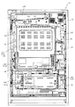
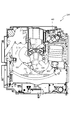
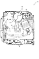
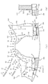
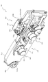
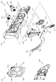
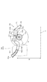
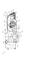
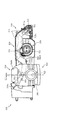
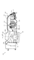
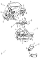
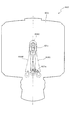
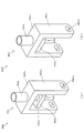
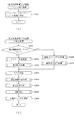
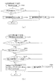
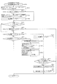
以下、本発明の実施形態について、添付図面を参照して説明する。まず、図1から図57を参照し、第1実施形態として、本発明をパチンコ遊技機(以下、単に「パチンコ機」という)10に適用した場合の一実施形態について説明する。図1は、第1実施形態におけるパチンコ機10の正面図であり、図2はパチンコ機10の遊技盤13の正面図であり、図3はパチンコ機10の後面図である。
Embodiments of the present invention will be described below with reference to the accompanying drawings. First, with reference to FIG. 1 to FIG. 57, an embodiment in which the present invention is applied to a pachinko gaming machine (hereinafter simply referred to as “pachinko machine”) 10 will be described as a first embodiment. FIG. 1 is a front view of a
図1に示すように、パチンコ機10は、略矩形状に組み合わせた木枠により外殻が形成される外枠11と、その外枠11と略同一の外形形状に形成され外枠11に対して開閉可能に支持された内枠12とを備えている。外枠11には、内枠12を支持するために正面視(図1参照)左側の上下2カ所に金属製のヒンジ18が取り付けられ、そのヒンジ18が設けられた側を開閉の軸として内枠12が正面手前側へ開閉可能に支持されている。
As shown in FIG. 1, the
内枠12には、多数の釘や入賞口63,64等を有する遊技盤13(図2参照)が裏面側から着脱可能に装着される。この遊技盤13の正面を球(遊技球)が流下することにより弾球遊技が行われる。なお、内枠12には、球を遊技盤13の正面領域に発射する球発射ユニット112a(図4参照)やその球発射ユニット112aから発射された球を遊技盤13の正面領域まで誘導する発射レール(図示せず)等が取り付けられている。
A game board 13 (see FIG. 2) having a large number of nails, winning
内枠12の正面側には、その正面上側を覆う正面枠14と、その下側を覆う下皿ユニット15とが設けられている。正面枠14及び下皿ユニット15を支持するために正面視(図1参照)左側の上下2カ所に金属製のヒンジ19が取り付けられ、そのヒンジ19が設けられた側を開閉の軸として正面枠14及び下皿ユニット15が正面手前側へ開閉可能に支持されている。なお、内枠12の施錠と正面枠14の施錠とは、シリンダ錠20の鍵穴21に専用の鍵を差し込んで所定の操作を行うことでそれぞれ解除される。
On the front side of the
正面枠14は、装飾用の樹脂部品や電気部品等を組み付けたものであり、その略中央部には略楕円形状に開口形成された窓部14cが設けられている。正面枠14の裏面側には2枚の板ガラスを有するガラスユニット16が配設され、そのガラスユニット16を介して遊技盤13の正面がパチンコ機10の正面側に視認可能となっている。
The
正面枠14には、球を貯留する上皿17が正面側へ張り出して上面を開放した略箱状に形成されており、この上皿17に賞球や貸出球などが排出される。上皿17の底面は正面視(図1参照)右側に下降傾斜して形成され、その傾斜により上皿17に投入された球が球発射ユニット112a(図4参照)へと案内される。また、上皿17の上面には、枠ボタン22が設けられている。この枠ボタン22は、例えば、第3図柄表示装置81(図2参照)で表示される演出のステージを変更したり、スーパーリーチの演出内容を変更したりする場合などに、遊技者により操作される。
On the
正面枠14には、その周囲(例えばコーナー部分)に各種ランプ等の発光手段が設けられている。これら発光手段は、大当たり時や所定のリーチ時等における遊技状態の変化に応じて、点灯又は点滅することにより発光態様が変更制御され、遊技中の演出効果を高める役割を果たす。窓部14cの周縁には、LED等の発光手段を内蔵した電飾部29〜33が設けられている。パチンコ機10においては、これら電飾部29〜33が大当たりランプ等の演出ランプとして機能し、大当たり時やリーチ演出時等には内蔵するLEDの点灯や点滅によって各電飾部29〜33が点灯または点滅して、大当たり中である旨、或いは大当たり一歩手前のリーチ中である旨が報知される。また、正面枠14の正面視(図1参照)左上部には、LED等の発光手段が内蔵され賞球の払い出し中とエラー発生時とを表示可能な表示ランプ34が設けられている。
The
また、右側の電飾部32下側には、正面枠14の裏面側を視認できるように裏面側より透明樹脂を取り付けて小窓35が形成され、遊技盤13正面の貼着スペースK1(図2参照)に貼付される証紙等がパチンコ機10の正面から視認可能とされている。また、パチンコ機10においては、より煌びやかさを醸し出すために、電飾部29〜33の周りの領域にクロムメッキを施したABS樹脂製のメッキ部材36が取り付けられている。
In addition, a
窓部14cの下方には、貸球操作部40が配設されている。貸球操作部40には、度数表示部41と、球貸しボタン42と、返却ボタン43とが設けられている。パチンコ機10の側方に配置されるカードユニット(球貸しユニット)(図示せず)に紙幣やカード等を投入した状態で貸球操作部40が操作されると、その操作に応じて球の貸出が行われる。具体的には、度数表示部41はカード等の残額情報が表示される領域であり、内蔵されたLEDが点灯して残額情報として残額が数字で表示される。球貸しボタン42は、カード等(記録媒体)に記録された情報に基づいて貸出球を得るために操作されるものであり、カード等に残額が存在する限りにおいて貸出球が上皿17に供給される。返却ボタン43は、カードユニットに挿入されたカード等の返却を求める際に操作される。なお、カードユニットを介さずに球貸し装置等から上皿17に球が直接貸し出されるパチンコ機、いわゆる現金機では貸球操作部40が不要となるが、この場合には、貸球操作部40の設置部分に飾りシール等を付加して部品構成は共通のものとしても良い。カードユニットを用いたパチンコ機と現金機との共通化を図ることができる。
A ball
上皿17の下側に位置する下皿ユニット15には、その中央部に上皿17に貯留しきれなかった球を貯留するための下皿50が上面を開放した略箱状に形成されている。下皿50の右側には、球を遊技盤13の正面へ打ち込むために遊技者によって操作される操作ハンドル51が配設される。
In the
操作ハンドル51の内部には、球発射ユニット112aの駆動を許可するためのタッチセンサ51aと、押下操作している期間中には球の発射を停止する発射停止スイッチ51bと、操作ハンドル51の回動操作量(回動位置)を電気抵抗の変化により検出する可変抵抗器(図示せず)などが内蔵されている。操作ハンドル51が遊技者によって右回りに回動操作されると、タッチセンサ51aがオンされると共に可変抵抗器の抵抗値が回動操作量に対応して変化し、その可変抵抗器の抵抗値に対応した強さ(発射強度)で球が発射され、これにより遊技者の操作に対応した飛び量で遊技盤13の正面へ球が打ち込まれる。また、操作ハンドル51が遊技者により操作されていない状態においては、タッチセンサ51aおよび発射停止スイッチ51bがオフとなっている。
Inside the
下皿50の正面下方部には、下皿50に貯留された球を下方へ排出する際に操作するための球抜きレバー52が設けられている。この球抜きレバー52は、常時、右方向に付勢されており、その付勢に抗して左方向へスライドさせることにより、下皿50の底面に形成された底面口が開口して、その底面口から球が自然落下して排出される。この球抜きレバー52の操作は、通常、下皿50の下方に下皿50から排出された球を受け取る箱(一般に「千両箱」と称される)を置いた状態で行われる。下皿50の右方には、上述したように操作ハンドル51が配設され、下皿50の左方には灰皿53が取り付けられている。
In the lower part of the front of the
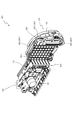
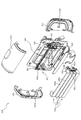
図2に示すように、遊技盤13は、正面視略正方形状に切削加工したベース板60に、球案内用の多数の釘(図示せず)や風車の他、レール61,62、一般入賞口63、第1入賞口64、第2入賞口640、第一可変入賞装置65、第2可変入賞装置650、スルーゲート67、可変表示装置ユニット80等を組み付けて構成され、その周縁部が内枠12(図1参照)の裏面側に取り付けられる。ベース板60は光透過性の樹脂材料からなり、その正面側からベース板60の後面側に配設された各種構造体を遊技者に視認させることが可能に形成される。一般入賞口63、第1入賞口64、第2入賞口640、第2可変入賞装置650、可変表示装置ユニット80は、ルータ加工によってベース板60に形成された貫通穴に配設され、遊技盤13の正面側からタッピングネジ等により固定されている。
As shown in FIG. 2, the
遊技盤13の正面中央部分は、正面枠14の窓部14c(図1参照)を通じて内枠12の正面側から視認することができる。以下に、主に図2を参照して、遊技盤13の構成について説明する。また、第1可変入賞装置65は、ルータ加工によって盤面下部ユニット300のベース部材310に形成された貫通穴に配設され、遊技盤13の正面側からタッピングネジ等により固定されている。
The front center portion of the
遊技盤13の正面には、帯状の金属板を略円弧状に屈曲加工して形成した外レール62が植立され、その外レール62の内側位置には外レール62と同様に帯状の金属板で形成した円弧状の内レール61が植立される。この内レール61と外レール62とにより遊技盤13の正面外周が囲まれ、遊技盤13とガラスユニット16(図1参照)とにより前後が囲まれることにより、遊技盤13の正面には、球の挙動により遊技が行われる遊技領域が形成される。遊技領域は、遊技盤13の正面であって2本のレール61,62とレール間を繋ぐ樹脂製の外縁部材73とにより区画して形成される領域(入賞口等が配設され、発射された球が流下する領域)である。
An
2本のレール61,62は、球発射ユニット112a(図4参照)から発射された球を遊技盤13上部へ案内するために設けられたものである。内レール61の先端部分(図2の左上部)には戻り球防止部材68が取り付けられ、一旦、遊技盤13の上部へ案内された球が再度球案内通路内に戻ってしまうといった事態が防止される。外レール62の先端部(図2の右上部)には、球の最大飛翔部分に対応する位置に返しゴム69が取り付けられ、所定以上の勢いで発射された球は、返しゴム69に当たって、勢いが減衰されつつ中央部側へ跳ね返される。
The two
遊技領域の正面視左側下部(図2の左側下部)には、発光手段である複数のLED及び7セグメント表示器を備える第1図柄表示装置37A,37Bが配設されている。第1図柄表示装置37A,37Bは、主制御装置110(図4参照)で行われる各制御に応じた表示がなされるものであり、主にパチンコ機10の遊技状態の表示が行われる。本実施形態では、第1図柄表示装置37A,37Bは、球が、第1入賞口64へ入賞したか、第2入賞口640へ入賞したかに応じて使い分けられるように構成されている。具体的には、球が、第1入賞口64へ入賞した場合には、第1図柄表示装置37Aが作動し、一方で、球が、第2入賞口640へ入賞した場合には、第1図柄表示装置37Bが作動するように構成されている。
First
また、第1図柄表示装置37A,37Bは、LEDにより、パチンコ機10が確変中か時短中か通常中であるかを点灯状態により示したり、変動中であるか否かを点灯状態により示したり、停止図柄が確変大当たりに対応した図柄か普通大当たりに対応した図柄か外れ図柄であるかを点灯状態により示したり、保留球数を点灯状態により示すと共に、7セグメント表示装置により、大当たり中のラウンド数やエラー表示を行う。なお、複数のLEDは、それぞれのLEDの発光色(例えば、赤、緑、青)が異なるよう構成され、その発光色の組み合わせにより、少ないLEDでパチンコ機10の各種遊技状態を示唆することができる。
In addition, the first
尚、本パチンコ機10では、第1入賞口64及び第2入賞口640へ入賞があったことを契機として抽選が行われる。パチンコ機10は、その抽選において、大当たりか否かの当否判定(大当たり抽選)を行うと共に、大当たりと判定した場合はその大当たり種別の判定も行う。ここで判定される大当たり種別としては、16R確変大当たり、16R時短大当たり、2R確変有時短無大当たり、が用意されている。第1図柄表示装置37A,37Bには、変動終了後の停止図柄として抽選の結果が大当たりであるか否かが示されるだけでなく、大当たりである場合はその大当たり種別に応じた図柄が示される。
In the
ここで、「16R確変大当たり」とは、最大ラウンド数が16ラウンドの大当たりの後に高確率状態へ移行するとともに時短状態となる大当たりのことであり、「2R確変有時短無大当たり」とは、最大ラウンド数が2ラウンドの大当たりの後に高確率状態へ移行するものの時短遊技は付与されない大当たりのことである。また、「16R時短大当たり」は、最大ラウンド数が16ラウンドの大当たりの後に、低確率状態へ移行すると共に、所定の変動回数の間(本実施形態では、100変動回数)は時短状態となる大当たりのことである。 Here, “16R probability variable jackpot” is a jackpot that shifts to a high-probability state after the maximum number of rounds is 16 round jackpot, and becomes a short-time state. Although the number of rounds shifts to a high probability state after a jackpot of two rounds, it is a jackpot that does not give a short-time game. In addition, “16R short-time jackpot” is a jackpot where the maximum number of rounds shifts to a low-probability state after a jackpot of 16 rounds, and during a predetermined number of fluctuations (in this embodiment, 100 fluctuations) That is.
また、「高確率状態」とは、大当たり終了後に付加価値としてその後の大当たり確率がアップした状態、いわゆる確率変動中(確変中)の時をいい、換言すれば、特別遊技状態へ移行し易い遊技の状態のことである。本実施形態における高確率状態(確変中)は、後述する第2図柄の当たり確率がアップして第2入賞口640へ球が入賞し易い遊技の状態を含む。「低確率状態」とは、確変中でない時をいい、大当たり確率が通常の状態、即ち、確変の時より大当たり確率が低い状態をいう。また、「低確率状態」のうちの時短状態(時短中)とは、大当たり確率が通常の状態であると共に、大当たり確率がそのままで第2図柄の当たり確率のみがアップして第2入賞口640へ球が入賞し易い遊技の状態のことをいう。一方、パチンコ機10が通常中とは、確変中でも時短中でもない遊技の状態(大当たり確率も第2図柄の当たり確率もアップしていない状態)である。
In addition, the “high probability state” means a state in which the jackpot probability thereafter increases as an added value after the jackpot ends, that is, when the probability change is in progress (probability change), in other words, a game that easily shifts to the special game state. It is a state of. The high probability state (during probability change) in the present embodiment includes a game state in which the hit probability of the second symbol, which will be described later, is increased and the ball is likely to win the second winning
確変中や時短中は、第2図柄の当たり確率がアップするだけではなく、第2入賞口640に付随する電動役物640aが開放される時間も変更され、通常中と比して長い時間が設定される。電動役物640aが開放された状態(開放状態)にある場合は、その電動役物640aが閉鎖された状態(閉鎖状態)にある場合と比して、第2入賞口640へ球が入賞しやすい状態となる。よって、確変中や時短中は、第2入賞口640へ球が入賞し易い状態となり、大当たり抽選が行われる回数を増やすことができる。
During probability change and time reduction, not only does the probability of winning the second symbol increase, but also the time for opening the
なお、確変中や時短中において、第2入賞口640に付随する電動役物640aの開放時間を変更するのではなく、または、その開放時間を変更することに加えて、1回の当たりで電動役物640aが開放する回数を通常中よりも増やす変更を行うものとしてもよい。また、確変中や時短中において、第2図柄の当たり確率は変更せず、第2入賞口640に付随する電動役物640aが開放される時間および1回の当たりで電動役物640aが開放する回数の少なくとも一方を変更するものとしてもよい。また、確変中や時短中において、第2入賞口640に付随する電動役物640aが開放される時間や、1回の当たりで電動役物640aを開放する回数はせず、第2図柄の当たり確率だけを、通常中と比してアップするよう変更するものであってもよい。
In addition, during the probability change or during the short time, it is not necessary to change the opening time of the
遊技領域には、球が入賞することにより5個から15個の球が賞球として払い出される複数の一般入賞口63が配設されている。また、遊技領域の中央部分には、可変表示装置ユニット80が配設されている。可変表示装置ユニット80には、第1入賞口64及び第2入賞口640への入賞(始動入賞)をトリガとして、第1図柄表示装置37A,37Bにおける変動表示と同期させながら、第3図柄の変動表示を行う液晶ディスプレイ(以下単に「表示装置」と略す)で構成された第3図柄表示装置81と、スルーゲート67の球の通過をトリガとして第2図柄を変動表示するLEDで構成される第2図柄表示装置(図示せず)とが設けられている。また、可変表示装置ユニット80には、第3図柄表示装置81の外周を囲むようにして、センターフレーム86が配設されている。
The game area is provided with a plurality of general winning
第3図柄表示装置81は9インチサイズの大型の液晶ディスプレイで構成されるものであり、表示制御装置114(図4参照)によって表示内容が制御されることにより、例えば上、中及び下の3つの図柄列が表示される。各図柄列は複数の図柄(第3図柄)によって構成され、これらの第3図柄が図柄列毎に横スクロールして第3図柄表示装置81の表示画面上にて第3図柄が可変表示されるようになっている。本実施形態の第3図柄表示装置81は、主制御装置110(図4参照)の制御に伴った遊技状態の表示が第1図柄表示装置37A,37Bで行われるのに対して、その第1図柄表示装置37A,37Bの表示に応じた装飾的な表示を行うものである。なお、表示装置に代えて、例えばリール等を用いて第3図柄表示装置81を構成するようにしても良い。
The third
第2図柄表示装置は、球がスルーゲート67を通過する毎に表示図柄(第2図柄(図示せず))としての「○」の図柄と「×」の図柄とを所定時間交互に点灯させる変動表示を行うものである。パチンコ機10では、球がスルーゲート67を通過したことが検出されると、当たり抽選が行われる。その当たり抽選の結果、当たりであれば、第2図柄表示装置において、第2図柄の変動表示後に「○」の図柄が停止表示される。また、当たり抽選の結果、外れであれば、第2図柄表示装置において、第3図柄の変動表示後に「×」の図柄が停止表示される。
Each time the sphere passes through the through
パチンコ機10は、第2図柄表示装置における変動表示が所定図柄(本実施形態においては「○」の図柄)で停止した場合に、第2入賞口640に付随された電動役物640aが所定時間だけ作動状態となる(開放される)よう構成されている。
In the
第2図柄の変動表示にかかる時間は、遊技状態が通常中の場合よりも、確変中または時短中の方が短くなるように設定される。これにより、確変中および時短中は、第2図柄の変動表示が短い時間で行われるので、当たり抽選を通常中よりも多く行うことができる。よって、当たり抽選において当たりとなる機会が増えるので、第2入賞口640の電動役物640aが開放状態となる機会を遊技者に多く与えることができる。よって、確変中および時短中は、第2入賞口640へ球が入賞しやすい状態とすることができる。
The time required for the variable display of the second symbol is set to be shorter during the probability change or during the shorter time than when the game state is normal. As a result, during the probability change and during the time reduction, since the variation display of the second symbol is performed in a short time, the winning lottery can be performed more than during normal. Therefore, since the chance of winning in the winning lottery increases, it is possible to give the player a lot of opportunities for the
なお、確変中または時短中において、当たり確率を高める、1回に当たりに対する電動役物640aの開放時間や開放回数を増やすなど、その他の方法によっても、確変中または時短中に第2入賞口640へ球が入賞しやすい状態としている場合は、第2図柄の変動表示にかかる時間を遊技状態にかかわらず一定としてもよい。一方、第2図柄の変動表示にかかる時間を、確変中または時短中において通常中よりも短く設定する場合は、当たり確率を遊技状態にかかわらず一定にしてもよいし、また、1回の当たりに対する電動役物640aの開放時間や開放回数を遊技状態にかかわらず一定にしてもよい。
It is to be noted that the probability of winning is increased during probability change or time reduction, and other methods such as increasing the opening time and the number of times of opening of the
スルーゲート67は、可変表示装置ユニット80の下側の領域における右方において遊技盤に組み付けられ、遊技盤に発射された球のうち、遊技盤の右方を流下する球の一部が通過可能に構成されている。スルーゲート67を球が通過すると、第2図柄の当たり抽選が行われる。当たり抽選の後、第2図柄表示装置にて変動表示を行い、当たり抽選の結果が当たりであれば、変動表示の停止図柄として「○」の図柄を表示し、当たり抽選の結果が外れであれば、変動表示の停止図柄として「×」の図柄を表示する。
The through
球のスルーゲート67の通過回数は、合計で最大4回まで保留され、その保留球数が上述した第1図柄表示装置37A,37Bにより表示されると共に第2図柄保留ランプ(図示せず)においても点灯表示される。第2図柄保留ランプは、最大保留数分の4つ設けられ、第3図柄表示装置81の下方に左右対称に配設されている。
The total number of passes through the through-gate 67 of the sphere is held up to a maximum of 4 times, and the number of held balls is displayed by the above-described first
なお、第2図柄の変動表示は、本実施形態のように、第2図柄表示装置において複数のランプの点灯と非点灯を切り換えることにより行うものの他、第1図柄表示装置37A,37B及び第3図柄表示装置81の一部を使用して行うようにしても良い。同様に、第2図柄保留ランプの点灯を第3図柄表示装置81の一部で行うようにしても良い。また、スルーゲート67の球の通過に対する最大保留球数は4回に限定されるものでなく、3回以下、又は、5回以上の回数(例えば、8回)に設定しても良い。また、スルーゲート67の組み付け数は1つに限定されるものではなく、複数(例えば、2つ)であっても良い。また、スルーゲート67の組み付け位置は可変表示装置ユニット80の右方に限定されるものではなく、例えば、可変表示装置ユニット80の左方でも良い。また、第1図柄表示装置37A,37Bにより保留球数が示されるので、第2図柄保留ランプにより点灯表示を行わないものとしてもよい。
Note that the variable display of the second symbol is performed by switching between lighting and non-lighting of a plurality of lamps in the second symbol display device as in the present embodiment, as well as the first
可変表示装置ユニット80の下方には、球が入賞し得る第1入賞口64が配設されている。この第1入賞口64へ球が入賞すると遊技盤13の裏面側に設けられる第1入賞口スイッチ(図示せず)がオンとなり、その第1入賞口スイッチのオンに起因して主制御装置110(図4参照)で大当たりの抽選がなされ、その抽選結果に応じた表示が第1図柄表示装置37Aで示される。
Below the
一方、第1入賞口64の正面視右方には、球が入賞し得る第2入賞口640が配設されている。この第2入賞口640へ球が入賞すると遊技盤13の裏面側に設けられる第2入賞口スイッチ(図示せず)がオンとなり、その第2入賞口スイッチのオンに起因して主制御装置110(図4参照)で大当たりの抽選がなされ、その抽選結果に応じた表示が第1図柄表示装置37Bで示される。
On the other hand, a second winning
また、第1入賞口64および第2入賞口640は、それぞれ、球が入賞すると5個の球が賞球として払い出される入賞口の1つにもなっている。なお、本実施形態においては、第1入賞口64へ球が入賞した場合に払い出される賞球数と第2入賞口640へ球が入賞した場合に払い出される賞球数とを同じに構成したが、第1入賞口64へ球が入賞した場合に払い出される賞球数と第2入賞口640へ球が入賞した場合に払い出される賞球数とを異なる数、例えば、第1入賞口64へ球が入賞した場合に払い出される賞球数を3個とし、第2入賞口640へ球が入賞した場合に払い出される賞球数を5個として構成してもよい。
Each of the first winning
第2入賞口640には電動役物640aが付随されている。この電動役物640aは開閉可能に構成されており、通常は電動役物640aが閉鎖状態(縮小状態)となって、球が第2入賞口640へ入賞しにくい状態となっている。一方、スルーゲート67への球の通過を契機として行われる第2図柄の変動表示の結果、「○」の図柄が第2図柄表示装置に表示された場合、電動役物640aが開放状態(拡大状態)となり、球が第2入賞口640へ入賞しやすい状態となる。
The second winning
上述した通り、確変中および時短中は、通常中と比して第2図柄の当たり確率が高く、また、第2図柄の変動表示にかかる時間も短いので、第2図柄の変動表示において「○」の図柄が表示され易くなって、電動役物640aが開放状態(拡大状態)となる回数が増える。更に、確変中および時短中は、電動役物640aが開放される時間も、通常中より長くなる。よって、確変中および時短中は、通常時と比して、第2入賞口640へ球が入賞しやすい状態を作ることができる。
As described above, the probability of hitting the second symbol is higher than that during normal change during the probability change and the short time, and the time required for the variation display of the second symbol is short. "Is easily displayed, and the number of times that the
ここで、第1入賞口64は、第2入賞口640にあるような電動役物は有しておらず、球が常時入賞可能な状態となっている。一方、第2入賞口640には電動役物640aが設けられており、通常時(時短中でない場合)は電動役物640aが開放され難く、第2入賞口640へ遊技球を入球させることが困難な状態となっている。
Here, the first winning
よって、通常中においては、第2入賞口640に付随する電動役物が閉鎖状態にある場合が多く、第2入賞口640に入賞しづらいので、電動役物のない第1入賞口64へ向けて、可変表示装置ユニット80の左方を球が通過するように球を発射し(所謂「左打ち」)、第1入賞口64への入賞によって大当たり抽選の機会を多く得て、大当たりとなることを狙った方が、遊技者にとって有利となる。
Therefore, during normal times, the electric winnings associated with the second winning
一方、確変中や時短中は、スルーゲート67に球を通過させることで、第2入賞口640に付随する電動役物640aが開放状態となりやすく、第2入賞口640に入賞しやすい状態であるので、第2入賞口640へ向けて、可変表示装置80の右方を球が通過するように球を発射し(所謂「右打ち」)、スルーゲート67を通過させて電動役物を開放状態にすると共に、第2入賞口640への入賞によって大当たり抽選の機会を多く得て、大当たりとなることを狙った方が、遊技者にとって有利となる。
On the other hand, during the probability change or during the short time, passing the ball through the through
このように、本実施形態のパチンコ機10は、パチンコ機10の遊技状態(確変中であるか、時短中であるか、通常中であるか)に応じて、遊技者に対し、球の発射の仕方を「左打ち」と「右打ち」とに変えさせることができる。よって、遊技者に対して、球の打ち方に変化をもたらすことができるので、遊技を楽しませることができる。
As described above, the
第1入賞口64の下方右側には第1可変入賞装置65が配設されており、その略中央部分に第1特定入賞口65aが設けられている。また、可変表示装置80の左側には第2可変入賞装置650が配設されており、その略中央部分に他の入賞口63,64,640と同程度の大きさの円形形状からなる第2特定入賞口650aが設けられている。パチンコ機10においては、第1入賞口64又は第2入賞口640への入賞に起因して行われた大当たり抽選が大当たりとなると、所定時間(変動時間)が経過した後に、大当たりの停止図柄となるよう第1図柄表示装置37A又は第1図柄表示装置37Bを点灯させると共に、その大当たりに対応した停止図柄を第3図柄表示装置81に表示させて、大当たりの発生が示される。その後、球が入賞し易い特別遊技状態(大当たり)に遊技状態が遷移する。この特別遊技状態として、通常時には閉鎖されている特定入賞口65a,650aが、所定時間(例えば、30秒経過するまで、或いは、球が10個入賞するまで)開放される。
A first variable winning
この特定入賞口65a,650aは、所定時間が経過すると閉鎖され、その閉鎖後、再度、その特定入賞口65a,650aが所定時間開放される。この特定入賞口65a,650aの開閉動作は、最高で例えば16回(16ラウンド)繰り返し可能にされている。この開閉動作が行われている状態が、遊技者にとって有利な特別遊技状態の一形態であり、遊技者には、遊技上の価値(遊技価値)の付与として通常時より多量の賞球の払い出しが行われる。
The specific winning
第1可変入賞装置65は、具体的には、第1特定入賞口65aを覆う横長矩形状の開閉板と、その開閉板の下辺を軸として右側に開閉駆動するための大開放口ソレノイド65b(図15参照、外形のみが図示される)とを備えている。第1特定入賞口65aは、通常時は、球が入賞できないか又は入賞し難い閉状態になっている。大当たりの際には大開放口ソレノイド65bを駆動して開閉板を正面側に傾倒し、球が第1特定入賞口65aに入賞しやすい開状態を一時的に形成し、その開状態と通常時の閉状態との状態を交互に繰り返すように作動する。
Specifically, the first variable winning
第2可変入賞装置650は、具体的には、第2特定入賞口650aの左方に配設される正面視三角形状の開閉板と、その開閉板の下辺を軸として左側に開閉駆動するための大開放口ソレノイド(図示せず)とを備えている。第2特定入賞口650aは、通常時は、球が入賞できないか又は入賞し難い閉状態になっている。大当たりの際には小開放口ソレノイドを駆動して開閉板を左方に傾倒し、球が第2特定入賞口650aに入賞しやすい開状態を一時的に形成し、その開状態と通常時の閉状態との状態を交互に繰り返すように作動する。
Specifically, the second variable prize-winning
本実施形態では、左打ちを行うことで第2可変入賞装置650に球を入賞させることが可能であるので、遊技状態が変化するごとに左打ちと、右打ちと、を切り替える煩わしさを解消することができる。
In this embodiment, it is possible to cause the second variable prize-winning
なお、上記した形態に特別遊技状態は限定されるものではない。特定入賞口65a,650aとは別に開閉される大開放口を遊技領域に設け、第1図柄表示装置37A,37Bにおいて大当たりに対応したLEDが点灯した場合に、特定入賞口65a,650aが所定時間開放され、その特定入賞口65a,650aの開放中に、球が特定入賞口65a,650a内へ入賞することを契機として特定入賞口65a,650aとは別に設けられた大開放口が所定時間、所定回数開放される遊技状態を特別遊技状態として形成するようにしても良い。また、特定入賞口65a,650aは1つに限るものではなく、1つ若しくは2以上の複数(例えば3つ)を配置しても良く、また配置位置も第1入賞口64の下方右側や、可変表示装置80の左側に限らず、例えば、第1入賞口64の下方でも良い。
Note that the special gaming state is not limited to the above-described form. When the game area is provided with a large opening that can be opened and closed separately from the
遊技盤13の下側における右隅部には、証紙や識別ラベル等を貼着するための貼着スペースK1が設けられ、貼着スペースK1に貼られた証紙等は、正面枠14の小窓35(図1参照)を通じて視認することができる。
A sticking space K1 for sticking a certificate paper, an identification label or the like is provided at the lower right corner of the
遊技盤13には、第1アウト口314及び第2アウト口315が設けられている。遊技領域を流下する球であって、いずれの入賞口63,64,65a,640,650aにも入賞しなかった球は、第1アウト口314又は第2アウト口315を通って図示しない球排出路へと案内される。第1アウト口314は、第1入賞口64の左側下方に配設される一方、第2アウト口315は、第1入賞口64の右側下方に配設される。即ち、第2アウト口315は、第1入賞口64を挟んで第1アウト口314の反対側に配設される。
The
よって、遊技領域を流下する球であって、第1入賞口64よりも正面視右側(図2右側)において遊技領域の下端(内レール61又は外縁部材73)に達した球は、内レール61又は外縁部材73の傾斜に沿って流下され、第2アウト口315を通って球排出路へ案内される一方、第1入賞口64よりも正面視左側において遊技領域の下端(内レール61)に達した球は、内レール61の傾斜(湾曲)に沿って流下され、第1アウト口314を通って球排出路へ案内される。
Therefore, a sphere that flows down the game area and reaches the lower end (the
遊技盤13には、球の落下方向を適宜分散、調整等するために多数の釘が植設されているとともに、風車等の各種部材(役物)とが配設されている。
A number of nails are planted on the
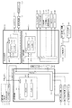
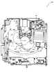
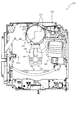
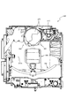
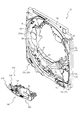
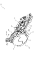
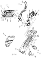
図3に示すように、パチンコ機10の後面側には、制御基板ユニット90,91と、裏パックユニット94とが主に備えられている。制御基板ユニット90は、主基板(主制御装置110)と音声ランプ制御基板(音声ランプ制御装置113)と表示制御基板(表示制御装置114)とが搭載されてユニット化されている。制御基板ユニット91は、払出制御基板(払出制御装置111)と発射制御基板(発射制御装置112)と電源基板(電源装置115)とカードユニット接続基板116とが搭載されてユニット化されている。
As shown in FIG. 3,
裏パックユニット94は、保護カバー部を形成する裏パック92と払出ユニット93とがユニット化されている。また、各制御基板には、各制御を司る1チップマイコンとしてのMPU、各種機器との連絡をとるポート、各種抽選の際に用いられる乱数発生器、時間計数や同期を図る場合などに使用されるクロックパルス発生回路等が、必要に応じて搭載されている。
The
なお、主制御装置110、音声ランプ制御装置113及び表示制御装置114、払出制御装置111及び発射制御装置112、電源装置115、カードユニット接続基板116は、それぞれ基板ボックス100〜104に収納されている。基板ボックス100〜104は、ボックスベースと該ボックスベースの開口部を覆うボックスカバーとを備えており、そのボックスベースとボックスカバーとが互いに連結されて、各制御装置や各基板が収納される。
The
また、基板ボックス100(主制御装置110)及び基板ボックス102(払出制御装置111及び発射制御装置112)は、ボックスベースとボックスカバーとを封印ユニット(図示せず)によって開封不能に連結(かしめ構造による連結)している。また、ボックスベースとボックスカバーとの連結部には、ボックスベースとボックスカバーとに亘って封印シール(図示せず)が貼着されている。この封印シールは、脆性な素材で構成されており、基板ボックス100,102を開封するために封印シールを剥がそうとしたり、基板ボックス100,102を無理に開封しようとすると、ボックスベース側とボックスカバー側とに切断される。よって、封印ユニット又は封印シールを確認することで、基板ボックス100,102が開封されたかどうかを知ることができる。
Further, the substrate box 100 (main control device 110) and the substrate box 102 (dispensing
払出ユニット93は、裏パックユニット94の最上部に位置して上方に開口したタンク130と、タンク130の下方に連結され下流側に向けて緩やかに傾斜するタンクレール131と、タンクレール131の下流側に縦向きに連結されるケースレール132と、ケースレール132の最下流部に設けられ、払出モータ216(図4参照)の所定の電気的構成により球の払出を行う払出装置133とを備えている。タンク130には、遊技ホールの島設備から供給される球が逐次補給され、払出装置133により必要個数の球の払い出しが適宜行われる。タンクレール131には、当該タンクレール131に振動を付加するためのバイブレータ134が取り付けられている。
The
また、払出制御装置111には状態復帰スイッチ120が設けられ、発射制御装置112には可変抵抗器の操作つまみ121が設けられ、電源装置115にはRAM消去スイッチ122が設けられている。状態復帰スイッチ120は、例えば、払出モータ216(図4参照)部の球詰まり等、払出エラーの発生時に球詰まりを解消(正常状態への復帰)するために操作される。操作つまみ121は、発射ソレノイドの発射力を調整するために操作される。RAM消去スイッチ122は、パチンコ機10を初期状態に戻したい場合に電源投入時に操作される。
The
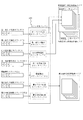
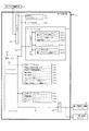
次に、図4を参照して、本パチンコ機10の電気的構成について説明する。図4は、パチンコ機10の電気的構成を示すブロック図である。
Next, the electrical configuration of the
主制御装置110には、演算装置である1チップマイコンとしてのMPU201が搭載されている。MPU201には、該MPU201により実行される各種の制御プログラムや固定値データを記憶したROM202と、そのROM202内に記憶される制御プログラムの実行に際して各種のデータ等を一時的に記憶するためのメモリであるRAM203と、そのほか、割込回路やタイマ回路、データ送受信回路などの各種回路が内蔵されている。主制御装置110では、MPU201によって、大当たり抽選や第1図柄表示装置37A,37B及び第3図柄表示装置81における表示の設定、第2図柄表示装置における表示結果の抽選といったパチンコ機10の主要な処理を実行する。
The
なお、払出制御装置111や音声ランプ制御装置113などのサブ制御装置に対して動作を指示するために、主制御装置110から該サブ制御装置へ各種のコマンドがデータ送受信回路によって送信されるが、かかるコマンドは、主制御装置110からサブ制御装置へ一方向にのみ送信される。
Various commands are transmitted from the
RAM203は、各種エリア、カウンタ、フラグのほか、MPU201の内部レジスタの内容やMPU201により実行される制御プログラムの戻り先番地などが記憶されるスタックエリアと、各種のフラグおよびカウンタ、I/O等の値が記憶される作業エリア(作業領域)とを有している。なお、RAM203は、パチンコ機10の電源の遮断後においても電源装置115からバックアップ電圧が供給されてデータを保持(バックアップ)できる構成となっており、RAM203に記憶されるデータは、すべてバックアップされる。
The
停電などの発生により電源が遮断されると、その電源遮断時(停電発生時を含む。以下同様)のスタックポインタや、各レジスタの値がRAM203に記憶される。一方、電源投入時(停電解消による電源投入を含む。以下同様)には、RAM203に記憶される情報に基づいて、パチンコ機10の状態が電源遮断前の状態に復帰される。RAM203への書き込みはメイン処理(図102参照)によって電源遮断時に実行され、RAM203に書き込まれた各値の復帰は電源投入時の立ち上げ処理(図101参照)において実行される。なお、MPU201のNMI端子(ノンマスカブル割込端子)には、停電等の発生による電源遮断時に、停電監視回路252からの停電信号SG1が入力されるように構成されており、その停電信号SG1がMPU201へ入力されると、停電時処理としてのNMI割込処理(図100)が即座に実行される。
When the power is shut down due to the occurrence of a power failure or the like, the stack pointer and the value of each register when the power is shut off (including when the power failure occurs, the same applies hereinafter) are stored in the
主制御装置110のMPU201には、アドレスバス及びデータバスで構成されるバスライン204を介して入出力ポート205が接続されている。入出力ポート205には、払出制御装置111、音声ランプ制御装置113、第1図柄表示装置37A,37B、第2図柄表示装置、第2図柄保留ランプ、特定入賞口65aの開閉板の下辺を軸として正面側に開閉駆動するための大開放口ソレノイドや電動役物を駆動するためのソレノイドなどからなるソレノイド209が接続され、MPU201は、入出力ポート205を介してこれらに対し各種コマンドや制御信号を送信する。
An input /
また、入出力ポート205には、図示しないスイッチ群およびスライド位置検出センサSや回転位置検出センサRを含むセンサ群などからなる各種スイッチ208、電源装置115に設けられた後述のRAM消去スイッチ回路253が接続され、MPU201は各種スイッチ208から出力される信号や、RAM消去スイッチ回路253より出力されるRAM消去信号SG2に基づいて各種処理を実行する。
The input /
払出制御装置111は、払出モータ216を駆動させて賞球や貸出球の払出制御を行うものである。演算装置であるMPU211は、そのMPU211により実行される制御プログラムや固定値データ等を記憶したROM212と、ワークメモリ等として使用されるRAM213とを有している。
The
払出制御装置111のRAM213は、主制御装置110のRAM203と同様に、MPU211の内部レジスタの内容やMPU211により実行される制御プログラムの戻り先番地などが記憶されるスタックエリアと、各種のフラグおよびカウンタ、I/O等の値が記憶される作業エリア(作業領域)とを有している。RAM213は、パチンコ機10の電源の遮断後においても電源装置115からバックアップ電圧が供給されてデータを保持(バックアップ)できる構成となっており、RAM213に記憶されるデータは、すべてバックアップされる。なお、主制御装置110のMPU201と同様、MPU211のNMI端子にも、停電等の発生による電源遮断時に停電監視回路252から停電信号SG1が入力されるように構成されており、その停電信号SG1がMPU211へ入力されると、停電時処理としてのNMI割込処理(図示せず)が即座に実行される。
The
払出制御装置111のMPU211には、アドレスバス及びデータバスで構成されるバスライン214を介して入出力ポート215が接続されている。入出力ポート215には、主制御装置110や払出モータ216、発射制御装置112などがそれぞれ接続されている。また、図示はしないが、払出制御装置111には、払い出された賞球を検出するための賞球検出スイッチが接続されている。なお、該賞球検出スイッチは、払出制御装置111に接続されるが、主制御装置110には接続されていない。
An input /
発射制御装置112は、主制御装置110により球の発射の指示がなされた場合に、操作ハンドル51の回動操作量に応じた球の打ち出し強さとなるよう球発射ユニット112aを制御するものである。球発射ユニット112aは、図示しない発射ソレノイドおよび電磁石を備えており、その発射ソレノイドおよび電磁石は、所定条件が整っている場合に駆動が許可される。具体的には、遊技者が操作ハンドル51に触れていることをタッチセンサ51aにより検出し、球の発射を停止させるための発射停止スイッチ51bがオフ(操作されていないこと)を条件に、操作ハンドル51の回動操作量(回動位置)に対応して発射ソレノイドが励磁され、操作ハンドル51の操作量に応じた強さで球が発射される。
The
音声ランプ制御装置113は、音声出力装置(図示しないスピーカなど)226における音声の出力、ランプ表示装置(電飾部29〜33、表示ランプ34など)227における点灯および消灯の出力、変動演出(変動表示)や予告演出といった表示制御装置114で行われる第3図柄表示装置81の表示態様の設定などを制御するものである。演算装置であるMPU221は、そのMPU221により実行される制御プログラムや固定値データ等を記憶したROM222と、ワークメモリ等として使用されるRAM223とを有している。
The sound
音声ランプ制御装置113のMPU221には、アドレスバス及びデータバスで構成されるバスライン224を介して入出力ポート225が接続されている。入出力ポート225には、主制御装置110、表示制御装置114、音声出力装置226、ランプ表示装置227、その他装置228、枠ボタン22などがそれぞれ接続されている。その他装置228には上下用駆動モータ431、開閉用駆動モータ466、その他駆動モータ531,561,631,661,751が含まれる。
An input /
ここで、各種駆動モータ(上下用駆動モータ431、開閉用駆動モータ466、その他駆動モータ531,561,631,661,751)について説明する。これらの各種駆動モータは、例えば、公知のステッピングモータで構成され、パチンコ機10に搭載されている各役物を動作させるために、各役物に対応付けて複数設けられている。この各種駆動モータは、対応するモータ制御用IC(モータドライバ)によって駆動される。具体的には、音声ランプ制御装置113のMPU221からモータ制御用IC(モータドライバ)に対して、回転のステップ数と、回転方向(正方向、または負方向)と、回転速度とを少なくとも含むコマンドを出力する。制御用IC(モータドライバ)は、出力されたコマンドに基づいて、対応する各種駆動モータを駆動する。なお、モータ制御用IC(モータドライバ)は、単一のICで複数の駆動モータに対して動作を設定可能なものを採用してもよいし、複数のモータ制御用IC(モータドライバ)を設けて別々の役物に対応する駆動モータをそれぞれ動作させるように構成してもよい。複数の駆動モータに対して動作を設定可能なモータ制御用IC(モータドライバ)を採用する場合は、回転ステップ数等を送信するためのコマンドに、駆動モータの種別を特定するための情報を含ませて出力すればよい。
Here, various drive motors (
ここで、上下用駆動モータ431を例に挙げて、駆動モータの動作について説明する。設定されたコマンドに基づいて、制御用IC(モータドライバ)が上下用駆動モータ431を動作させる場合は、1ステップの動作を実行させる毎に、音声ランプ制御装置113のMPU221に対して動作を実行させたことを通知するための信号(実行信号)が出力される。この実行信号により、MPU221は、設定した動作の進捗を把握することができる。なお、音声ランプ制御装置113のRAM223には、図示しないステップカウンタが設けられている。このステップカウンタは、役物毎に設けられており、各役物が原点(退避)位置から何ステップ分動作したのかをカウントするカウンタである。即ち、原点(退避)位置を0ステップの位置として、制御用ICからの実行信号を受信する度にその値が1ずつ更新される。より具体的には、役物が原点(退避)位置から終点(張出)位置へと向かう方向(正方向)へ1ステップ動作する毎にその値が1ずつ加算される。また、終点(張出)位置から原点(退避)位置へと向かう方向(負方向)へ1ステップ動作する毎にその値が1ずつ減算される。よって、ステップカウンタの値に基づいて各役物の動作位置を容易に把握することができる。
Here, the operation of the drive motor will be described using the
ここで、原点位置とは、役物毎に設定されている特定の配置を指し、電源投入に基づく原点復帰において移行する位置のことである。具体的には、各役物には、原点位置か否かを検出するための原点センサ(図示せず)が設けられており、電源投入時に原点センサがオンでなければ、原点センサがオンを検出するまで役物を可変させる(即ち、各種駆動モータを駆動する)。この原点位置が、各役物の動作の基準位置となる。なお、上述したステップカウンタは、原点復帰により役物が原点位置となった場合(即ち、原点センサがオンを検出した場合)に、0にリセットされる。そして、上述した通り、モータ制御用ICより出力される実行信号に基づいて、ステップカウンタの値が1ずつ更新される。 Here, the origin position refers to a specific arrangement that is set for each accessory, and is a position that shifts in origin return based on power-on. Specifically, each accessory is provided with an origin sensor (not shown) for detecting whether or not it is the origin position. If the origin sensor is not on when the power is turned on, the origin sensor is turned on. The accessory is varied until it is detected (that is, various drive motors are driven). This origin position becomes the reference position for the operation of each accessory. Note that the above-described step counter is reset to 0 when the accessory reaches the origin position by the origin return (that is, when the origin sensor detects ON). As described above, the value of the step counter is updated one by one based on the execution signal output from the motor control IC.
次いで、モータ制御用IC(モータドライバ)による各種駆動モータ(ここでは上下用駆動モータ431)の制御の一例について、図135を参照して説明する。なお、説明を分かり易くするために、1ステップで90度回転する(即ち、4ステップで1周する)ステッピングモータを例に取って説明するが、実際の上下用駆動モータ431は、1ステップの回転角度をより細かく設定できるように構成されている。具体的には、1ステップで1度回転するように構成されている。
Next, an example of control of various drive motors (here, the vertical drive motor 431) by the motor control IC (motor driver) will be described with reference to FIG. In order to make the explanation easy to understand, a stepping motor that rotates 90 degrees in one step (that is, rotates once in four steps) will be described as an example. However, an actual
まず、図135(a)は、ステッピングモータで構成される上下用駆動モータ431の概要を示す図である。この上下用駆動モータ431は、対応するモータ制御用ICに対して音声ランプ制御装置113から励磁制御データを送ることにより、その励磁制御データに対応した部位が励磁されるように構成されている。具体的には、図135(a)に示す「A,B,C,D」に対応した4桁の2進数で構成された励磁制御データによって、モータ制御用ICにより励磁される。具体的には、上下用駆動モータ431の各部位(即ち、A,B,C,Dのいずれか)に対応する励磁制御データが「1」であれば励磁され、励磁制御データが「0」であれば励磁されない。例えば、励磁制御のデータが「1100」であれば、A及びBが励磁され、CおよびDは励磁されない。この励磁制御データは、音声ランプ制御装置113のROM222に設けられている励磁テーブル(図135(b)参照)に規定されている。
First, FIG. 135 (a) is a diagram showing an outline of a
また、音声ランプ制御装置113には、励磁テーブル(図135(b)参照)に規定された複数の励磁制御データの中から1の励磁制御データを選択して設定するために用いられる励磁カウンタが設けられている。この励磁カウンタは、「0」を起点として正方向に1ずつ更新することができ、励磁カウンタの値が「3」となってから値が更新されると値が「0」に戻るループカウンタとなっている。この励磁カウンタ値が更新される度に、対応する励磁制御データが読み出されて設定される。励磁制御データが設定されると、励磁制御データに基づく各部位の励磁が即座に行われる(即ち、励磁制御データの設定からタイムラグなく上下用駆動モータ431が動作する)。更に、励磁カウンタは、負の方向にも更新することができる。つまり、値が「0」を起点として、「0」→「3」→「2」→「1」→「0」の順番に更新することができる。負方向に更新する場合は、正方向に更新した場合と上下用駆動モータ431の回転方向が逆向きになる。励磁カウンタを更新する方向(正方向であるか、負方向であるか)と、励磁カウンタの更新頻度とは、動作を設定する役物の種別毎に予め定められている。なお、この励磁カウンタの最大値は、駆動モータのステップ数に応じて変化する。具体的には、例えば、1ステップで1度回転する(即ち、モータが1回転するのに360ステップを要する)駆動モータの場合、励磁カウンタは「0」〜「359」の範囲で更新されるループカウンタとなる。
In addition, the sound
次いで、上下用駆動モータ431の各部位を励磁するための励磁制御データの具体例について、図135(b)を参照して説明する。図135(b)は、励磁制御データを規定した励磁テーブルと、その励磁テーブルに規定された励磁制御データに基づいて励磁された上下用駆動モータ431の状態との対応関係を示す図である。なお、図135(b)に示した通り、励磁テーブルには、励磁カウンタの値毎に励磁制御データが規定されている。
Next, a specific example of excitation control data for exciting each part of the
具体的には、図135(b)に示した通り、上下用駆動モータ431に対応するシーケンスデータとして、励磁カウンタ「0」〜「3」の順に「1100,0110,0011,1001」の励磁制御データがそれぞれ規定されている。また、励磁カウンタ値「0」に対応するシーケンスデータである「1100」が設定されると、上下用駆動モータ431のA、およびBの各位置が励磁される。また、励磁カウンタ値「1」に対応するシーケンスデータである「0110」が設定されると、上下用駆動モータ431のB、およびCの各位置が励磁されるので、励磁カウンタ値が「0」の状態から時計回りに90度回転する。また、励磁カウンタ値「2」に対応するシーケンスデータである「0011」が設定されると、上下用駆動モータ431のC、およびDの各位置が励磁され、励磁カウンタ値が「1」の状態から時計回りに90度回転する。また、励磁カウンタ値「3」に対応するシーケンスデータである「1001」が設定されると、上下用駆動モータ431のA、およびDの各位置が励磁されるので、励磁カウンタ値が「2」の状態から時計回りに90度回転する。このように、図135に示した例では、励磁カウンタの値が正方向に1更新される毎に、上下用駆動モータ431が時計回りに90度ずつ回転する。なお、上述した通り、励磁カウンタの値が負方向に更新される場合は、上下用駆動モータ431が反時計回りに90度ずつ回転する。
Specifically, as shown in FIG. 135 (b), excitation control of “1100, 0110, 0011, 1001” in the order of excitation counters “0” to “3” as sequence data corresponding to the
以上のように、上下用駆動モータ431の制御を、簡略化した動作モデルで説明したが、本実施形態で実際に用いられる上下用駆動モータ431では、1ステップ毎に(即ち、励磁カウンタを1更新する毎に)1度ずつ回転させることができる。即ち、各役物を可変させる場合は、可変させるステップ数に応じた回数だけ励磁カウンタの値を1ずつ更新し、励磁カウンタの更新毎に励磁カウンタに対応する励磁制御データを設定することで、正確に各役物を可変させることができる。
As described above, the control of the
このように、本実施形態では、モータドライバに対してコマンドを設定することにより、コマンドで指定した回転速度、回転方向、および回転ステップ数で各種駆動モータを駆動させることができる。よって、役物を用いた多彩な演出動作を実現することができる。 As described above, in this embodiment, by setting a command to the motor driver, various drive motors can be driven at the rotation speed, the rotation direction, and the number of rotation steps specified by the command. Therefore, it is possible to realize a variety of performance operations using an accessory.
なお、各役物には、演出に応じた固有の動作パターンが設定されている。この動作パターンは、上述したモータ制御用IC(モータドライバ)に対して設定するコマンドを、経過時間毎に規定したものである。 Note that a unique operation pattern corresponding to the production is set for each accessory. This operation pattern defines a command to be set for the motor control IC (motor driver) described above for each elapsed time.
また、本実施形態では、モータドライバに対して設定したコマンドに基づいて各種駆動モータが動作完了したか否かを、各種駆動モータが動作したステップ数に基づいて判断している。即ち、コマンドにより設定したステップ数と、モータドライバにより1ステップの動作が設定される度にモータドライバから出力される実行信号の受信回数とに基づいて、各種駆動モータに設定した動作が完了したか否かを判断しているが、これに限られるものではない。例えば、各種駆動モータを動作させるためのコマンドを設定してからの経過時間を計測し、その経過時間に基づいて各種駆動モータの動作が完了したか否かを判別するように構成してもよい。 In the present embodiment, whether or not the various drive motors have been operated is determined based on the number of steps in which the various drive motors are operated based on a command set for the motor driver. That is, based on the number of steps set by the command and the number of times the execution signal received from the motor driver is received each time one step of operation is set by the motor driver, has the operation set for each drive motor been completed? It is determined whether or not, but is not limited to this. For example, an elapsed time after setting a command for operating various drive motors may be measured, and it may be configured to determine whether the operation of the various drive motors has been completed based on the elapsed time. .
ここで、本実施形態において協調して制御される上下用駆動モータ431と開閉用駆動モータ466との制御について説明する。詳細は後述の第1制御例において説明するが、本実施形態では、上下動作ユニット装置(落下役物)400が可動する演出(落下役物シナリオ)として、上下動作ユニット装置(落下役物)400のレンズ部材460と扉部材470とが上下用駆動モータ431の駆動により、落下方向へ可動される演出が設けられている。当該演出(落下役物シナリオ)では、レンズ部材460と扉部材470とが落下方向へ可動された後、扉部材470が開閉用駆動モータ466により開放される演出と、開放されない演出とが設けられている。
Here, control of the
本実施形態における音声ランプ制御装置113は、当該演出(落下役物シナリオ)において扉部材470が開放される演出が実行されている場合に、扉部材470を開閉するための開閉用駆動モータ466に対して、AからDの全ての位置に対する励磁がオフとなるように制御(通電停止制御)する(図108のS1706参照)。全ての位置に対する励磁がオフである場合は、開閉用駆動モータ466の静止トルク(所謂、ディテントルク)、即ち、扉部材470を閉状態で維持するトルクは最小となる。この場合に、上下用駆動モータ431が駆動し、スライド部材450が落下方向へ可動されると、扉部材470へ慣性力が発生する。
In the present embodiment, the sound
ここで、本実施形態では、上述した扉部材470を閉状態で維持するトルク(静止トルク)が、扉部材470へと発生する慣性力よりも小さくなるように構成されている。これにより、扉部材470を開放するために開閉用駆動モータ466を駆動せずともスライド部材450が落下方向へ可動される際に、扉部材470に発生する慣性力によって、扉部材470を閉状態から開状態へと開放することができる。よって、開閉用モータ466を駆動するための消費電力を低減することができる。
Here, in the present embodiment, the above-described torque for maintaining the
なお、スライド部材450の移動に伴い扉部材470に発生する慣性力が、扉部材470を開放するのに充分でない場合には、開閉用駆動モータ466を駆動して開放するようにしてもよい。この場合においては、スライド部材450の移動に伴い扉部材470に発生する慣性力を用いることで、開閉用駆動モータ466の駆動トルクを低減することができ、消費電力の低減や、開閉用駆動モータ466の小型化を図ることができる。
If the inertial force generated in the
また、演出パターンに応じて、開閉用モータ466を駆動して扉部材470を開放する場合と、開閉用モータ466を駆動せずに扉部材470を開放する場合とを切り替えても良い。例えば、期待度の高い演出パターンの実行時には、扉部材470を確実に開放するために開閉用モータ466を駆動して扉部材470を開放し、一方、期待度の低い演出パターンの実行時には、開閉用モータ466を駆動せずに扉部材470を開放するようにする。これにより、期待度の高い演出パターンにも関わらず、扉部材470が開放されないとの不具合を抑制することができる。
Further, the case where the
さらに、上下用駆動モータ431が駆動し、スライド部材450が落下方向へ可動されない場合、即ち、扉部材470に慣性力が働かない場合には、扉部材470を閉状態で維持するトルク(静止トルク)が扉部材470を閉状態で維持するのに充分なトルクとなるように構成されている。このため、落下役物シナリオが実行されない期間においても、開閉用駆動モータ466を励磁して扉部材470を閉状態で維持する必要がなく、消費電力の低減を図ることができる。なお、扉部材470を閉状態で維持するトルク(静止トルク)が扉部材470を閉状態で維持するのに必要なトルクが不足している場合は、例えば、扉部材470の先端部分に磁石を設けることで、扉部材470を閉状態で維持するのに必要なトルクが少なくなるように構成してもよい。
Further, when the
一方、演出(落下役物シナリオ)として扉部材470が開放されない演出が実行されている場合は、扉部材を開閉するための開閉用駆動モータ466が回転しないように励磁制御される。具体的には、上述した励磁テーブル(図135(b)のうち、現在の励磁カウンタに基づいて該当する部位(AからD)を一定時間励磁し続けることで、開閉用駆動モータ466には停止位置を保とうとするトルク(所謂、ホールディングトルク)が発生し、扉部材470が閉状態で維持されることになる。これにより、扉部材470が開放されない演出であるにも関わらず、スライド部材450が落下方向へ可動される際の勢い(慣性力)によって、扉部材470が開放されてしまうことを確実に防止できる。
On the other hand, when an effect in which the
なお、上述した扉部材470の開閉制御とその開閉制御によって制御された扉部材470の開閉状態とが一致しない場合は、その後に実行される演出を変更するようにしてもよい。
In addition, when the opening / closing control of the
具体的には、扉部材470が開放される落下役物シナリオに基づく演出が実行されている場合に、開閉用駆動モータ466が通電停止制御され、その後、扉部材470が開放されることで、扉部材470の背面側に位置するレンズ部材460が視認可能となる。そして、遊技者はそのレンズ部材460を通して第3図柄表示装置81に表示される「激アツ」との文字を視認することができる。レンズ部材460を通して第3図柄表示装置81の表示を視認することで、当該表示が拡大されて表示されることとなり、遊技者に対して当該表示をより印象的に感じさせることができる。
Specifically, when an effect based on a dropped actor scenario in which the
一方、開閉用駆動モータ466が通電停止制御されたものの、扉部材470が開放されなかった場合には、第3図柄表示装置81に「激アツ」との文字が表示されているにも関わらず、扉部材470が開放され、レンズ部材460が視認できる演出であるにも関わらず、扉部材470が開放されないとの不具合が発生したとの印象を与えてしまうことになる。そこで、当該演出において、開閉用駆動モータ466が通電停止制御されたものの、扉部材470が開放されなかったことを扉部材470が状態を検知可能な原点センサなどにより検出し、その場合には、その後に第3図柄表示装置81に「激アツ」との文字が表示されないように演出を変更する。これにより、扉部材470が開放されずとも、第3図柄表示装置81に「激アツ」との文字が表示されないため、扉部材470が開放されない演出が実行されたと遊技者に認識させることができ、上述した不具合が発生したとの印象を与えることがないようにできる。この場合において、特定のLEDを点灯させたり、外部出力端子を通してホールコンピュータへ通知することで、当該不具合が発生したことを従業員に対して報知するようにしてもよい。
On the other hand, when the opening /
また、上下動作ユニット装置(落下役物)400のレンズ部材460と扉部材470とを落下させるシナリオとして、一度の動作で退避位置から張出位置まで移動させるシナリオと、複数の動作(例えば、2度)で退避位置から張出位置まで移動させるシナリオとを設けるようにしてもよい。これにより、開閉用駆動モータ466が通電停止制御されているにも関わらず、その後、扉部材470が開放されなかった場合に、2度目の動作で扉部材470を開放したとしても、2度の動作によって扉部材470が退避位置から張出位置へと移動する演出であると感じさせることができ、遊技者に対して違和感を与えることがないようにできる。
Further, as a scenario in which the
さらに、扉部材470が開放される落下役物シナリオと、扉部材470が開放されない落下役物シナリオとで、上下用駆動モータ431の駆動速度を変更し、扉部材470に働く慣性力を変化するように構成してもよい。具体的には、扉部材470が開放される落下役物シナリオでは、上下用駆動モータ431の駆動速度を速くし、扉部材470に働く慣性力が大きくなるようにし、一方、扉部材470が開放されない落下役物シナリオでは、上下用駆動モータ431の駆動速度を遅くし、扉部材470に働く慣性力が小さくなるようにする。これにより、扉部材470の開閉を精度よく制御することができる。落下役物のシナリオに応じて上下用駆動モータ431の駆動速度を変更するものには限られず、同一の落下役物シナリオにおいても、例えば、上方向へ移動させる場合と、下方向へ移動させる場合とで上下用駆動モータ431の駆動速度を変更するようにしてもよい。
Further, the inertial force acting on the
また、演出パターンに応じて、開閉用モータ466を駆動して扉部材470を開放する場合と、開閉用モータ466を駆動せずに扉部材470を開放する場合とを切り替えても良い。例えば、期待度の高い演出パターンの実行時には、扉部材470を確実に開放するために開閉用モータ466を駆動して扉部材470を開放し、一方、期待度の低い演出パターンの実行時には、開閉用モータ466を駆動せずに扉部材470を開放するようにする。これにより、期待度の高い演出パターンにも関わらず、扉部材470が開放されないとの不具合を抑制することができる。
Further, the case where the
次いで、本実施形態では、入出力ポート225にRTC(リアルタイムクロック)292が接続されている。このRTC292は、時間を計時するための計時手段であり、専用の内部電源(本実施形態では、電池)が備えられているので、パチンコ機10に電源が供給されていない状態においても計時を継続することができる。ここで、パチンコ機10を製造する場合に、計時手段に同じ時刻(例えば、現在時刻)を設定して製造することで、複数のパチンコ機10において同一の時刻情報を取得することが可能となる。このように構成することで、時間演出を複数のパチンコ機10間で同期して実行することができる。この時間演出の詳細については、後述の第1制御例において具体的に説明する。なお、計時手段(RTC)による計時の精度を向上させるために、外部から時刻情報を補正するための補正手段(GPSや電波時計など)を設けても良い。
Next, in this embodiment, an RTC (real time clock) 292 is connected to the input /
また、外部から時刻情報を補正するための補正手段(例えば、GPSや電波時計など)により、パチンコ機10に電源が供給される度(立ち上げられる度)に、時刻情報を補正するようにしてもよい。これにより、専用の内部電源(本実施形態では、電池)を設けなくとも、パチンコ機10に電源が供給される度(立ち上げられる度)に、計時手段による時刻情報を更新することができるため、計時手段の製造コストやメンテナンスコスト(内部電源の劣化による交換費用など)を低減することができる。なお、補正手段による時刻情報の補正は、パチンコ機10に電源が供給される度(立ち上げられる度)に限られず、定期的(例えば、1時間毎)に実行するようにしてもよい。 Further, every time power is supplied to the pachinko machine 10 (every time it is started up), the time information is corrected by a correction means for correcting the time information from the outside (for example, a GPS or a radio clock). Also good. Thereby, the time information by the time measuring means can be updated every time power is supplied to the pachinko machine 10 (every time it is started up) without providing a dedicated internal power supply (battery in this embodiment). In addition, it is possible to reduce manufacturing costs and maintenance costs (such as replacement costs due to deterioration of the internal power supply) of the time measuring means. The correction of the time information by the correction means is not limited to every time power is supplied to the pachinko machine 10 (every time it is started up), but may be executed periodically (for example, every hour).
音声ランプ制御装置113は、主制御装置110から受信した各種のコマンド(変動パターンコマンド、停止種別コマンド等)に基づいて、第3図柄表示装置81の表示態様を決定し、決定した表示態様をコマンド(表示用変動パターンコマンド、表示用停止種別コマンド等)によって表示制御装置114へ通知する。また、音声ランプ制御装置113は、枠ボタン22からの入力を監視し、遊技者によって枠ボタン22が操作された場合は、第3図柄表示装置81で表示されるステージを変更したり、スーパーリーチ時の演出内容を変更したりするように、表示制御装置114へ指示する。ステージが変更される場合は、変更後のステージに応じた後面画像を第3図柄表示装置81に表示させるべく、変更後のステージに関する情報を含めた後面画像変更コマンドを表示制御装置114へ送信する。ここで、後面画像とは、第3図柄表示装置81に表示させる主要な画像である第3図柄の後面側に表示される画像のことである。表示制御装置114は、この音声ランプ制御装置113から送信されるコマンドに従って、第3図柄表示装置81に各種の画像を表示する。
The sound
また、音声ランプ制御装置113は、表示制御装置114から第3図柄表示装置81の表示内容を表すコマンド(表示コマンド)を受信する。音声ランプ制御装置113では、表示制御装置114から受信した表示コマンドに基づき、第3図柄表示装置81の表示内容に合わせて、その表示内容に対応する音声を音声出力装置226から出力し、また、その表示内容に対応させてランプ表示装置227の点灯および消灯を制御する。
Further, the sound
表示制御装置114は、音声ランプ制御装置113及び第3図柄表示装置81が接続され、音声ランプ制御装置113より受信したコマンドに基づいて、第3図柄表示装置81における第3図柄の変動演出などの表示を制御するものである。また、表示制御装置114は、第3図柄表示装置81の表示内容を通知する表示コマンドを適宜音声ランプ制御装置113へ送信する。音声ランプ制御装置113は、この表示コマンドによって示される表示内容にあわせて音声出力装置226から音声を出力することで、第3図柄表示装置81の表示と音声出力装置226からの音声出力とをあわせることができる。
The
ここで、表示制御装置114により第3図柄表示装置81に表示される表示内容について説明する。第3図柄は、「0」から「9」の数字の主図柄により構成されている。また、本実施形態のパチンコ機10においては、後述する主制御装置110により行われる特別図柄の抽選結果が大当たりであった場合に、同一の主図柄が揃う変動表示が行われ、その変動表示が終わった後に大当たりが発生するよう構成されている。一方、特別図柄の抽選結果が外れであった場合は、同一の主図柄が揃わない変動表示が行われる。
Here, the display content displayed on the 3rd
例えば、特別図柄の抽選結果が「大当たりA」または「大当たりC」であれば、奇数番号である「1,3,4,7,9」の主図柄が揃って停止表示される変動表示が行われる。また、「大当たりB」であれば、偶数番号である「0,2,4,6,8」の主図柄が揃う変動表示が行われる。 For example, if the special symbol lottery result is “big hit A” or “big hit C”, a variable display is displayed in which the main symbols of “1, 3, 4, 7, 9”, which are odd numbers, are aligned and stopped. Is called. Further, if “big hit B”, the variable display in which the main symbols of “0, 2, 4, 6, 8” which are even numbers are aligned is performed.
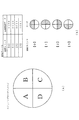
第3図柄表示装置81の表示画面は、大きくは上下に2分割され、上側の2/3が第3図柄を変動表示する主表示領域Dm、それ以外の下側の1/3が予告演出、キャラクタおよび保留球数などを表示する副表示領域Dsとなっている。
The display screen of the third
主表示領域Dmは、左・中・右の3つの表示領域Dm1〜Dm3に区分けされており、その3つの表示領域Dm1〜Dm3に、それぞれ3つの図柄列Z1,Z2,Z3が表示される。各図柄列Z1〜Z3には、上述した第3図柄が規定の順序で表示される。即ち、各図柄列Z1〜Z3には、数字の昇順に主図柄が配列され、各図柄列Z1〜Z3毎に周期性をもって上から下へとスクロールして変動表示が行われる。この主表示領域Dmの略中央が有効ラインL1として設定されており、毎回の遊技に際して、左図柄列Z1→右図柄列Z3→中図柄列Z2の順に、有効ラインL1上に第3図柄が停止表示される。その第3図柄の停止時に有効ラインL1上に大当たり図柄の組合せ(本実施形態では、同一の主図柄の組合せ)で揃えば大当たりとして大当たり動画が表示される。 The main display area Dm is divided into three display areas Dm1 to Dm3 of left, middle, and right, and three symbol rows Z1, Z2, and Z3 are displayed in the three display areas Dm1 to Dm3, respectively. In each symbol row Z1 to Z3, the above-described third symbols are displayed in a prescribed order. That is, the main symbols are arranged in ascending numerical order in the symbol rows Z1 to Z3, and the symbols are scrolled from top to bottom with periodicity for each symbol row Z1 to Z3. The approximate center of the main display area Dm is set as the active line L1, and in each game, the third symbol is stopped on the active line L1 in the order of the left symbol row Z1, the right symbol row Z3, and the middle symbol row Z2. Is displayed. If the combination of jackpot symbols (the same main symbol combination in this embodiment) is arranged on the effective line L1 when the third symbol is stopped, a jackpot moving image is displayed as a jackpot.
一方、副表示領域Dsは、主表示領域Dmよりも下方に横長に設けられており、さらに左右方向に3つの小領域Ds1〜Ds3に等区分されている。このうち、小領域Ds1は、第1入賞口64に入球された球のうち変動が未実行である球(保留球)の数である保留球数を表示する領域であり、小領域Ds2は、予告演出画像を表示する領域であり、小領域Ds3は、第2入賞口640に入球した球のうち変動が未実行である球(保留球)の数である保留球数を表示する領域である。
On the other hand, the sub display area Ds is horizontally long below the main display area Dm, and is further equally divided into three small areas Ds1 to Ds3 in the left-right direction. Among these, the small area Ds1 is an area for displaying the number of reserved balls, which is the number of balls that have not been changed among the balls that have entered the first winning opening 64 (reserved balls), and the small area Ds2 is The area for displaying the notice effect image, and the small area Ds3 is the area for displaying the number of reserved balls, which is the number of balls (reserved balls) that have not been changed among the balls that have entered the second winning
実際の表示画面では、主表示領域Dmに第3図柄の主図柄が合計3個停止表示される。なお、変動表示される場合には、中央部に表示される主図柄以外にも、その前後に配置された主図柄が視認可能に表示されるので、最大で合計9個主図柄が表示される場合もある。副表示領域Dsにおいては、保留球1つに対して「●」図柄が一つ表示されて、特別図柄1、特別図柄2に対してそれぞれ最大4個までの保留球に対応して保留図柄が表示される。即ち、副表示領域Dsには、最大で8個の保留図柄が表示される。
On the actual display screen, a total of three main symbols of the third symbol are stopped and displayed in the main display area Dm. In the case of variable display, in addition to the main symbols displayed at the center, the main symbols arranged before and after the main symbol are displayed so as to be visible, so a total of nine main symbols are displayed at the maximum. In some cases. In the sub display area Ds, one “●” symbol is displayed for one reserved ball, and the reserved symbols corresponding to up to four reserved balls for each of the
なお、本実施形態では、特別図柄1と特別図柄2とで同じ保留図柄(デザイン)としたが、それに限らず、異なる図柄(例えば、特別図柄1に対しては、「●」図柄として、特別図柄2に対しては、「□」図柄)で表示するように構成してもよい。
In the present embodiment, the same reserved symbol (design) is used for the
これにより、第1入賞口64と第2入賞口640との保留球、即ち、特別図柄1と特別図柄2との保留球をそれぞれ識別し易く表示することができる。また、普通図柄の当たり種別により第2入賞口640へ入球した保留球の表示態様を異なるように表示したので、遊技者に、長時間当たりで発生した保留球であることを容易に判別させることができる。
Thereby, the reserved balls of the first winning
なお、本実施形態では、第3図柄表示装置81の主表示領域Dm、副表示領域Dsには、上記した、主図柄、保留図柄等以外にも文字表示やキャラクタ等の予告演出表示や、総変動回数の表示等が適宜表示される。また、保留図柄が表示されていない場合は、保留球数が0球である、即ち、保留球が存在しないことを示す。
In the present embodiment, the main display area Dm and the sub display area Ds of the third
なお、本実施形態においては、第1入賞口64への入球は、最大4回まで保留されるように構成したが、最大保留球数は4回に限定されるものでなく、3回以下、又は、5回以上の回数(例えば、8回)に設定しても良い。また、小領域Ds1または小領域Ds3における保留球数図柄の表示に代えて、保留球数を第3図柄表示装置81の一部に数字で、或いは、4つに区画された領域を保留球数分だけ異なる態様(例えば、色や点灯パターン)にして表示するようにしても良い。また、第1図柄表示装置37により保留球数が示されるので、第3図柄表示装置81に保留球数を表示させないものとしてもよい。更に、可変表示装置ユニット80に、保留球数を示す保留ランプを最大保留数分の4つ設け、点灯状態の保留ランプの数に応じて、保留球数を表示するものとしてもよい。
In the present embodiment, the ball entering the first winning
また、表示制御装置114には、サブ表示装置690が接続されている。このサブ表示装置690は、第3図柄表示装置81と解像度が異なる表示装置(例えば、液晶パネル)となっている。具体的には、第3図柄表示装置81の解像度は(横800×縦600)となっており、サブ表示装置690の解像度は(横400×縦300)となっている(図82参照)。なお、第3図柄表示装置81とサブ表示装置690との解像度はそれぞれ上述したものと異なるものであってもよいし、サブ表示装置690の解像度と第3図柄表示装置81とは同一の解像度であってもよいし、第3図柄表示装置81よりもサブ表示装置690の解像度が高いものであってもよい。
Further, a
詳細は図81を参照して後述するが、本実施形態における表示制御装置114は、第3図柄表示装置81とサブ表示装置690とに対して第3図柄表示装置81とサブ表示装置690とのそれぞれに表示する画像を包含する一の画像データ(本実施形態では横1200×縦600の解像度の画像データ)を用いて表示制御を行う。その一の画像データのうち第3図柄表示装置81の解像度に該当する部分の画像データ(横800×縦600の領域)が第3図柄表示装置81に表示され、残りの部分におけるサブ表示装置690の解像度に該当する部分の画像データ(横400×縦300の領域)がサブ表示装置690に表示される。なお、残りのデータ(横400×縦300の領域)は未使用となる。
The details will be described later with reference to FIG. 81, but the
これにより、第3図柄表示装置81とサブ表示装置690とに表示する表示内容の同期をとることが容易となり、第3図柄表示装置81とサブ表示装置690とに表示される表示内容とがずれてしまう不具合を抑制することができる。
This makes it easy to synchronize the display contents displayed on the third
電源装置115は、パチンコ機10の各部に電源を供給するための電源部251と、停電等による電源遮断を監視する停電監視回路252と、RAM消去スイッチ122(図3参照)が設けられたRAM消去スイッチ回路253とを有している。電源部251は、図示しない電源経路を通じて、各制御装置110〜114等に対して各々に必要な動作電圧を供給する装置である。その概要としては、電源部251は、外部より供給される交流24ボルトの電圧を取り込み、各種スイッチ208などの各種スイッチや、ソレノイド209などのソレノイド、モータ等を駆動するための12ボルトの電圧、ロジック用の5ボルトの電圧、RAMバックアップ用のバックアップ電圧などを生成し、これら12ボルトの電圧、5ボルトの電圧及びバックアップ電圧を各制御装置110〜114等に対して必要な電圧を供給する。
The
停電監視回路252は、停電等の発生による電源遮断時に、主制御装置110のMPU201及び払出制御装置111のMPU211の各NMI端子へ停電信号SG1を出力するための回路である。停電監視回路252は、電源部251から出力される最大電圧である直流安定24ボルトの電圧を監視し、この電圧が22ボルト未満になった場合に停電(電源断、電源遮断)の発生と判断して、停電信号SG1を主制御装置110及び払出制御装置111へ出力する。停電信号SG1の出力によって、主制御装置110及び払出制御装置111は、停電の発生を認識し、NMI割込処理を実行する。なお、電源部251は、直流安定24ボルトの電圧が22ボルト未満になった後においても、NMI割込処理の実行に充分な時間の間、制御系の駆動電圧である5ボルトの電圧の出力を正常値に維持するように構成されている。よって、主制御装置110及び払出制御装置111は、NMI割込処理(図示せず)を正常に実行し完了することができる。
The power
RAM消去スイッチ回路253は、RAM消去スイッチ122(図3参照)が押下された場合に、主制御装置110へ、バックアップデータをクリアさせるためのRAM消去信号SG2を出力するための回路である。主制御装置110は、パチンコ機10の電源投入時に、RAM消去信号SG2を入力した場合に、バックアップデータをクリアすると共に、払出制御装置111においてバックアップデータをクリアさせるための払出初期化コマンドを払出制御装置111に対して送信する。
The RAM erase
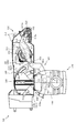
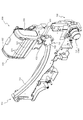
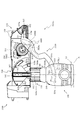
次いで、図5から図12を参照して、遊技盤13及び動作ユニット200について説明する。まず、図5から図7を参照して、背面ケース210への各ユニット300〜700の収容構造について説明する。
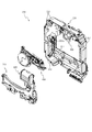
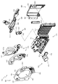
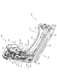
Next, the
図5は、遊技盤13及び動作ユニット200の分解正面斜視図であり、図6及び図7は、分解した動作ユニット200を正面視した動作ユニット200の分解正面斜視図である。なお、図7では、複合動作ユニット500が背面ケース210に装着された状態が図示される。
FIG. 5 is an exploded front perspective view of the
図5から図7に示すように、動作ユニット200は、底壁部211と、その底壁部211の外縁から立設される外壁部212とから一面側(図6紙面手前側)が開放された箱状に形成される背面ケース210を備える。背面ケース210は、その底壁部211の中央に矩形状の開口211aが開口形成されることで、正面視矩形の枠状に形成される。開口211aは、第3図柄表示装置81(図2参照)の外形に対応した(即ち、第3図柄表示装置81を配設可能な)大きさに形成される。
As shown in FIGS. 5 to 7, the
動作ユニット200は、背面ケース210の内部空間に、上下動作ユニット400、複合動作ユニット500、傾倒動作ユニット600及びスライド動作ユニット700がそれぞれ収容され、これを1ユニットとして構成される。
The
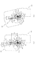
具体的には、複合動作ユニット500は、背面ケース210の外壁部212の内側面が形成する領域の右上部に配設される(図7参照)。この図7に示す状態に対し、傾倒動作ユニット600及びスライド動作ユニット700が背面ケース210の外壁部212の内側面が形成する領域の下部に配設される。また、この図7に示す状態に対し、上下動作ユニット400は複合動作ユニット500の正面側に、重ね合わされた積層状態で配設され、背面ケース210に収容される(図5参照)。
Specifically, the
このように、本実施形態では、所定の動作ユニット(例えば、複合動作ユニット500)に対し、他の動作ユニット(例えば、上下動作ユニット400)が正面側に重ね合わされた積層状態で配設されるので、正面視において、所定の動作ユニットを、他の動作ユニットによって遮蔽することができる。 As described above, in the present embodiment, a predetermined operation unit (for example, the combined operation unit 500) is disposed in a stacked state in which another operation unit (for example, the vertical operation unit 400) is superimposed on the front side. Therefore, the predetermined operation unit can be shielded by another operation unit in the front view.
言い換えれば、遊技盤13(図2参照)が光透過性材料から形成され、その遊技盤13の背面側に配設される動作ユニットを遊技者が視認可能とされる場合に、所定の動作ユニットの必要な部分のみを遊技者に視認させ、他の部分を他の動作ユニットにより遊技者から遮蔽することができる。これにより、他の動作ユニットによって遮蔽される所定の演出部材については、その全体が遊技者から視認されることを前提として設計する必要がないので、その設計の自由度の向上を図ることができる。
In other words, when the game board 13 (see FIG. 2) is formed of a light-transmitting material and the player can visually recognize the operation unit disposed on the back side of the
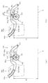
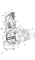
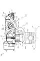
次いで、図8から図10を参照して、上下動作ユニット400、複合動作ユニット500、傾倒動作ユニット600及びスライド動作ユニット700の動作態様の概略について説明する。なお、図8から図10の説明においては、図5から図7を適宜参照する。
Next, with reference to FIGS. 8 to 10, an outline of operation modes of the
図8から図10は、動作ユニット200の正面図である。なお、図8では上下動作ユニット400のアーム部材440(図18参照)が張出位置に配置された状態が、図9では複合動作ユニット500の伸縮演出装置540(図26参照)が伸張状態を形成された状態が、図10では傾倒動作ユニット600が幅方向略中央に配置された状態が、それぞれ図示される。
8 to 10 are front views of the
図8に示すように、上下動作ユニット400は、アーム部材440(図18参照)を、図5に示す退避位置と図8に示す張出位置との間で動作させる。図5に示す退避位置では、アーム部材440は、背面ケース210の開口211aの上方に退避され、遊技者から視認不能とされる(図2参照)。一方、図8に示す張出位置では、アーム部材440が下降され、レンズ部材460(図18参照)が背面ケース210の開口211aの中央(即ち、第3図柄表示装置81の正面、図2参照)に配置される。
As shown in FIG. 8, the
図9に示すように、複合動作ユニット500は、回動アーム部材550(図22参照)が下方へ張り出す張出位置へ配置され前板部材546が背面ケース210の開口211aの中央(即ち、第3図柄表示装置81の正面、図2参照)に配設される伸張状態と、回動アーム部材550が上方へ退避される退避位置へ配置され前板部材546が背面ケース210の開口211aの上方に退避される縮小状態(図5参照)と、を形成可能とされる。図5に示す縮小状態では、前板部材546は、背面ケース210の開口211aの上方に退避され、遊技者から視認不能とされる(図2参照)。
As shown in FIG. 9, the
図10に示すように、傾倒動作ユニット600は、スライド動作ユニット700の支柱部材720(図47参照)が左右にスライド移動されることで、図5に示す退避位置と、図10に示す張出位置との間で移動可能とされる。図5に示す退避位置では、傾倒動作ユニット600は、背面ケース210の開口211aの右外方に退避され、センターフレーム86の内側において遊技者から視認される(図2参照)。一方、図10に示す張出位置では、傾倒動作ユニット600が背面ケース210の開口211aの中央(即ち、第3図柄表示装置81の正面、図2参照)に配置される。
As shown in FIG. 10, the tilting
なお、図10では、第1カーテン部材624及び第2カーテン部材625(図46参照)が開放され、内部の液晶装置が視認される状態が図示される。即ち、図10の状態に傾倒動作ユニット600が配置されると、開口211aを通して視認される第3図柄表示装置81(図2参照)に表示される演出と、傾倒動作ユニット600の内部の液晶装置に表示される演出との両方を遊技者に視認させることができる。
FIG. 10 illustrates a state in which the
これら各動作ユニット400〜700は、それぞれ独立して動作可能に形成されると共に、上述したように、重ね合わされた(積層された)状態で配設されるので、各動作ユニット400〜700のうちの層を違えて配設されるものについては、例え動作部材が背面ケース210の開口211aの内方に張り出す態様のものであっても同時に動作させることができる。即ち、図8から図10で例示したように、各動作ユニット400〜700をそれぞれ単体で動作させるだけでなく、これらの動作を組み合わせることができるので、その演出効果を高めることができる。
Each of these
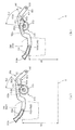
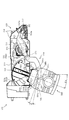
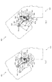
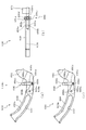
図11は、動作ユニット200の正面図である。なお、図11では、複合動作ユニット500の伸縮演出装置540(図22参照)が伸張状態とされ、上下動作ユニット400のアーム部材440及びレンズ部材460が張出位置に配置されると共に扉部材470が開放状態を形成される。
FIG. 11 is a front view of the
図11に示すように、上下動作ユニット400のレンズ部材460を通して、複合動作ユニット500の前板部材546が視認される。レンズ部材460には、後述するように、拡大レンズ加工が形成されるので、前板部材546が拡大視される。
As shown in FIG. 11, the
即ち、図11に示す状態から、複合動作ユニット500の回転板520(図24参照)が第1軸部512(図24参照)を中心に揺動動作され、前板部材546が上下動作ユニット400のレンズ部材470から正面視で離間する位置(図39参照)まで移動されると、前板部材546は通常の大きさで視認される。これにより、前板部材546が通常の大きさで視認される状態と、拡大視される状態(図11参照)とを切り替えることができ、演出効果を向上させることができる。
That is, from the state shown in FIG. 11, the rotary plate 520 (see FIG. 24) of the combined
図12は、動作ユニット200の正面図である。なお、図12では、複合動作ユニット500の伸縮演出装置540(図22参照)が伸張状態とされ、傾倒動作ユニット600が退避位置に配置され傾倒状態とされ、傾倒動作ユニット600と前板部材546とが当接する直前の状態が図示される。傾倒動作ユニット600が更に傾倒されることで、傾倒動作ユニット600と前板部材546とは当接される。この場合に、複合動作ユニット500を正面視時計回りに揺動させることで(図39参照)、あたかも、傾倒動作ユニット600から複合動作ユニット500に力が加えられるように見せる演出を行うことができる(ユニット同士の動作を関連付け、より複雑な演出を行うことができる)。これにより、演出効果を向上させることができる。
FIG. 12 is a front view of the
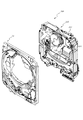
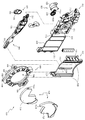
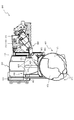
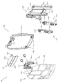
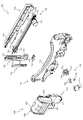
次いで、図13から図15を参照して、盤面下部ユニット300について説明する。図13は、盤面13と盤面下部ユニット300との正面分解斜視図である。図13に示すように、遊技盤13の下部には、内レール61の下縁に沿って開口され盤面下部ユニット300が挿通される受け入れ開口13aが形成される。
Next, the panel surface
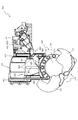
図14は、盤面下部ユニット300の正面分解斜視図である。図14に示すように、盤面下部ユニット300は、遊技盤13の受け入れ開口13aに内嵌固定されるベース部材310と、そのベース部材310の正面視左下方に配設され球を第1アウト口314へ案内する左下板部材320と、ベース部材310の正面視右下方に配設され球を第2アウト口315へ案内する右下板部材330と、正面からベース部材310に締結固定され左下板部材320及び右下板部材330が挿通軸343で軸支される前蓋部材340と、を主に備える。
FIG. 14 is a front exploded perspective view of the board surface
ベース部材310は、遊技盤13の受け入れ開口13aの形状と略同等の形状であり受け入れ開口13aよりも若干小さな断面形状に形成される板状の本体部311と、その本体部311の正面側を覆う態様で薄板状に形成される装飾前板部312と、その装飾前板部312の幅方向略中央部に取り付けられる可動演出部材313と、その可動演出部材313の正面視左方に形成される矩形状孔である第1アウト口314と、可動演出部材313の正面視右方に形成される矩形状孔である第2アウト口315と、を主に備える。
The
可動演出部材313は、遊技盤13の幅方向中心下縁に配設され、図示しない駆動装置により回転される回転演出部材313aを備える。ここで、遊技盤13の幅方向中心下縁にアウト口が配設される場合、可動演出部材313を遊技盤13の幅方向中心下縁に配置することはできない。本実施形態では、遊技盤13の幅方向中心下縁にアウト口を配設せず、遊技盤13の中心から左右に離間した位置に第1アウト口314及び第2アウト口315を配設することで、可動演出部材313を遊技盤13の幅方向中心下縁に配設するスペースを確保することができる。
The
図15を参照して、第1アウト口314、第2アウト口315、左下板部材320及び右下板部材330の形状について説明する。図15(a)は、ベース部材310、第1アウト口314、第2アウト口315、左下板部材320及び右下板部材330の正面図であり、図15(b)は、図15(a)のXVb−XVb線におけるベース部材310及び左下板部材320の断面図である。なお、図15(a)では、ベース部材310に締結固定される前蓋部材340の外形と、第1アウト口314及び第2アウト口315の上方に形成される釘とが図示される。
With reference to FIG. 15, the shape of the 1st out
第1アウト口314及び第2アウト口315は、遊技領域から球が排出される開口である。第1アウト口314に比較して第2アウト口315は幅方向の形成長さが短くされる。その理由については後述する。また、第2アウト口315の上内側面に前後方向へ延設される案内リブ315aが形成される。その案内リブ315aにより、第2アウト口315へ流入する球が高くはね、第2アウト口315の上底面に衝突する場合に球に加えられる抵抗を抑制することができる。また、第2アウト口315から排出される球の流れを前後方向に整えることができ、排出される球の方向のばらつきを抑制することができる。
The first out
また、後述する左下板部材320の緩衝リブ322は、遊技盤13(図13参照)の幅方向中央へ向かうほど高く形成される(図15(a)参照)。これにより、遊技盤13の幅方向中央へ向かうほど遊技領域の上下幅が大きくなる本実施形態においても、左下板部材320に落下する球の跳ね返りを抑制する効果を損ねることがない。即ち、遊技盤13の幅方向中央に近いほど、球の落下高さは高くなるので、落下した球が左下板部材320に衝突した場合の衝撃が大きくなる恐れがある。これに対し、緩衝リブ322は遊技盤13の幅方向中央へ向かうほど高く形成されるので、遊技盤13の幅方向中央に近いほど緩衝リブ322が撓むことで落下の衝撃を和らげるクッション効果の度合いを大きくすることができる。
Further, a
ここで、緩衝リブ322,332の縦横比と、落下する球の着地頻度との関係について説明する。例えば、緩衝リブ322,332に着地する球の落下高さは高いが、その位置に球が到達する頻度が極端に低い場合、わざわざ球の跳ね返りを抑制せずとも、他の球の排出の障害にならない場合がある。この場合にまで緩衝リブ322,332の縦横比を大きく形成すると、遊技領域のスペースを不必要に抑制することになる。従って、緩衝リブ322,332の縦横比は、球の落下高さのみでなく、落下高さと、その位置に球が着地する頻度との関係で設定されることが好ましい。
Here, the relationship between the aspect ratio of the
図15に示すように、緩衝リブ322,332の上方を流下する球は経路c1,c2で流下開始され、その後複数の分岐b1〜b10を経て、着地領域z0〜z4に到達する。なお、以下の説明では、球が流下する確率が経路c1とc2とで等しく(1/2)、分岐b1〜b10での左右への分岐の確率がそれぞれ左右均等(1/2)である場合を説明する。なお、右上方から球が流下されることは無いものと仮定する。
As shown in FIG. 15, the sphere flowing down above the
着地領域z0に球が到達する確率について説明する。着地領域z0に到達するためには、分岐b5で左側を流下して経路c11に到達する必要がある。分岐b5までは、経路c1から分岐b1を経て到達する場合と、経路c2から到達する場合とが考えられる。そのため、球が経路c11に到達して、着地領域z0に球が到達する確率は、経路c1から流下される球の確率1/8(=1/2×(1/2)^2)と、経路c2から流下される球の確率1/4(=1/2×1/2)との総和で表されるので、3/8である(「^」はべき乗を意味する)。即ち、それぞれの確率は、経路c1,c2を球が流下する確率1/2と、着地領域z0に到達するまでに球が通る分岐b1〜b10の数だけ1/2を累乗した数との積で表される。
The probability that a sphere will reach the landing area z0 will be described. In order to reach the landing area z0, it is necessary to flow down the left side at the branch b5 and reach the path c11. It can be considered that the branch b5 is reached from the route c1 via the branch b1 and the route c2 is reached. Therefore, the probability that the sphere reaches the path c11 and the sphere reaches the landing area z0 is the probability of the sphere flowing down from the
着地領域z1に球が到達する確率について説明する。着地領域z1に到達するためには、分岐b3で左側を流下して経路c15に到達するか、分岐b4で左側を流下して経路c16に到達するか、分岐b6で右側を流下して経路c14に到達するか、分岐b7で右側を流下して経路c13に到達する必要がある。 The probability that a sphere will reach the landing area z1 will be described. In order to reach the landing area z1, the branch b3 flows down the left side to reach the path c15, the branch b4 flows down the left side and reaches the path c16, or the branch b6 flows down the right side to reach the path c14. Or it is necessary to flow down the right side at the branch b7 to reach the path c13.
分岐b3までは、経路c1から球が流下される場合のみが考えられ、球が経路c15に到達するまでに分岐が3つ存在するので、球が経路c15に到達する確率は1/16(=1/2×(1×2)^3)である。また、分岐b4までは、経路c1から球が流下される場合のみが考えられ、球が経路c16に到達するまでに分岐が4つ存在するので、球が経路c16に到達する確率は1/32(=1/2×(1×2)^4)である。また、分岐b6までは、経路c1から球が流下される場合のみが考えられ、球が経路c14に到達するまでに分岐が3つ存在するので、球が経路c14に到達する確率は1/16(=1/2×(1×2)^3)である。 Up to the branch b3, only the case where the sphere flows down from the path c1 can be considered. Since there are three branches before the sphere reaches the path c15, the probability that the sphere reaches the path c15 is 1/16 (= 1/2 × (1 × 2) ^ 3). Also, until the branch b4, only the case where the sphere flows down from the path c1 can be considered, and there are four branches until the sphere reaches the path c16, so the probability that the sphere reaches the path c16 is 1/32 (= 1/2 × (1 × 2) ^ 4). Further, until the branch b6, only the case where the sphere flows down from the path c1 can be considered. Since there are three branches before the sphere reaches the path c14, the probability that the sphere reaches the path c14 is 1/16. (= 1/2 × (1 × 2) ^ 3).
分岐b7までは、経路c1及び経路c2から球が流下される場合の両方が考えられ、経路c1から流下した球が経路c13に到達するまでに分岐が4つ存在する場合と、分岐が3つ存在する場合がある。経路c2から流下した球が経路c13に到達するまでに分岐が2つ存在する。そのため、球が経路c13に到達する確率は、経路c1から流下される球の確率3/32(=1/2×(1/2)^4+1/2×(1/2)^3)と、経路c2から流下される球の確率1/8(=1/2×(1/2)^2)との総和で表されるので、7/32である。 Up to the branch b7, both cases where the sphere flows down from the path c1 and the path c2 are conceivable. There are four branches and three branches before the sphere flowing down from the path c1 reaches the path c13. May exist. There are two branches until the sphere flowing down from the path c2 reaches the path c13. Therefore, the probability that the sphere reaches the path c13 is 3/32 (= 1/2 × (1/2) ^ 4 + 1/2 × (1/2) ^ 3), which is the probability of the sphere flowing down from the path c1. This is 7/32 because it is expressed by the sum of the probability of the sphere flowing down from the path c2 and 1/8 (= 1/2 × (1/2) ^ 2).
ここで、着地領域z1に球が到達する確率は、上述した経路c13〜c16に球が到達する確率の総和であるので、12/32である。 Here, the probability that the sphere reaches the landing region z1 is 12/32 because it is the sum of the probability that the sphere reaches the paths c13 to c16 described above.
着地領域z2に球が到達する確率について説明する。着地領域z2に球が到達する確率は、経路c12に球が到達する確率で表せ、これは、分岐b7に到達した球が経路c13に到達する確率と等しくなる。そのため、着地領域z2に球が到達する確率は7/32である。 The probability that a sphere will reach the landing area z2 will be described. The probability that the sphere reaches the landing area z2 can be expressed by the probability that the sphere reaches the route c12, which is equal to the probability that the sphere that reaches the branch b7 reaches the route c13. Therefore, the probability that the sphere reaches the landing area z2 is 7/32.
着地領域z3に球が到達する確率について説明する。着地領域z3に到達するためには、分岐b9で左側を流下して経路c17に到達するか、分岐b10で左側を流下して経路c18に到達する必要がある。 The probability that a sphere will reach the landing area z3 will be described. In order to reach the landing area z3, it is necessary to flow down the left side at the branch b9 to reach the path c17, or flow down the left side at the branch b10 to reach the path c18.
分岐b9までは、経路c1から球が流下される場合のみが考えられ、球が経路c17に到達するまでに分岐が6つ存在するので、球が経路c17に到達する確率は1/128(=1/2×(1×2)^6)である。また、分岐b10までは、経路c1から球が流下される場合のみが考えられ、球が経路c18に到達するまでに分岐が7つ存在するので、球が経路c18に到達する確率は1/256(=1/2×(1×2)^7)である。 Up to the branch b9, only the case where the sphere flows down from the path c1 can be considered. Since there are six branches before the sphere reaches the path c17, the probability that the sphere reaches the path c17 is 1/128 (= 1/2 × (1 × 2) ^ 6). Further, until the branch b10, only the case where the sphere flows down from the path c1 is considered. Since there are seven branches before the sphere reaches the path c18, the probability that the sphere reaches the path c18 is 1/256. (= 1/2 × (1 × 2) ^ 7).
着地領域z3に球が到達する確率は、上述した経路c17及びc18に球が到達する確率の総和であるので、3/256である。 The probability of the sphere reaching the landing area z3 is 3/256 because it is the sum of the probability of the sphere reaching the paths c17 and c18 described above.
着地領域z4に球が到達する確率について説明する。着地領域z4に到達するためには、分岐b10で右側を流下して経路c19に到達する必要がある。なお、分岐b10の右側を流下した球は全て経路c19で流下するものとする。経路c19に球が到達する確率は、分岐b10に到達した球が経路c18に到達する確率と等しくなる。そのため、着地領域z4に球が到達する確率は1/256(=1/2×(1×2)^7)である。 The probability that a sphere will reach the landing area z4 will be described. In order to reach the landing area z4, it is necessary to flow down the right side at the branch b10 to reach the path c19. It is assumed that all the spheres that have flowed down on the right side of the branch b10 flow down along the path c19. The probability that the sphere reaches the path c19 is equal to the probability that the sphere that reaches the branch b10 reaches the path c18. Therefore, the probability that the sphere reaches the landing area z4 is 1/256 (= 1/2 × (1 × 2) ^ 7).
これらのことから、各着地領域z0〜z4へ球が到達する割合は、(z0:z1:z2:z3:z4)=(96:96:56:3:1)となる。この割合は、緩衝リブ322,332と相関関係を有する。
From these facts, the rate at which the sphere reaches each landing area z0 to z4 is (z0: z1: z2: z3: z4) = (96: 96: 56: 3: 1). This ratio has a correlation with the
例えば、着地領域z1と着地領域z3とを比較すると、各着地領域z1,z3に落下する球の高さは同等であるのに緩衝リブ322,332の縦横比は着地領域z3の方が着地領域z1より小さい。これは、着地領域z3に球が到達する割合が、着地領域z1に球が到達する割合の1/32であるためである。即ち、落下する球のバウンドを着地領域z1ほどに抑制せずとも、着地領域z3においては球の排出が滞るおそれが小さい。そこで、着地領域z3においては、着地領域z1に比較して緩衝リブ332の縦横比を小さくすることで、第2アウト口315の配設位置を下方へ下げることができる。
For example, when comparing the landing area z1 and the landing area z3, the heights of the spheres falling on the landing areas z1 and z3 are the same, but the aspect ratio of the
例えば、着地領域z2と着地領域z4とを比較すると、着地領域z2への球の落下距離よりも着地領域z4への球の落下距離の方が長いのに、緩衝リブ322,332の縦横比は着地領域z2の方が着地領域z4より大きい。これは、着地領域z4に球が到達する割合が、着地領域z2に球が到達する割合の1/56であるためである。即ち、落下する球のバウンドを着地領域z2ほどに抑制せずとも、着地領域z4においては球の排出が滞るおそれが小さい。そこで、着地領域z4においては、着地領域z2に比較して緩衝リブ332の縦横比を小さくすることで、第2アウト口315の配設位置を下方へ下げることができる。
For example, when comparing the landing area z2 and the landing area z4, the aspect ratio of the
なお、上述した説明では、分岐b1〜b10の球の分岐の確率は、左右均等(1/2)である場合を説明したが、釘の幅を変化させることで、分岐b1〜b10で球が分岐する確率を調整することが可能である。例えば、分岐b1の左側の矢印が通る流路の釘の間隔を球の直径と同程度に小さくすることで、分岐b1で球が右側の矢印に沿って流下する確率を1/2よりも大きくすることができる。他の分岐b2〜b10においても、同様に球の分岐の確率を調整することができる。 In the above description, the probability of branching of the spheres of the branches b1 to b10 is equal to the left and right (1/2). However, by changing the width of the nail, the spheres at the branches b1 to b10 are changed. It is possible to adjust the probability of branching. For example, by reducing the distance between the nails in the flow path through which the left arrow of the branch b1 passes to the same extent as the diameter of the sphere, the probability of the sphere flowing down along the right arrow at the branch b1 is greater than ½. can do. In the other branches b2 to b10, the probability of branching of the sphere can be adjusted similarly.
これにより、経路c11〜c19に球が到達する頻度を調整することができ、緩衝リブ322の縦横比の設計自由度を向上させることができる。
Thereby, the frequency with which a sphere reaches the paths c11 to c19 can be adjusted, and the degree of freedom in designing the aspect ratio of the
また、緩衝リブ322は上面が後方へ向かうにつれて下降傾斜して形成される(図15(b)参照)。これにより、第1アウト口314への球流れを速くすることができる。
Further, the
図14に戻って説明する。左下板部材320は、長尺板状の本体部321と、その本体部321の上面において左右方向に連設される薄厚の板がそれぞれ前後方向に延設される緩衝リブ322と、その緩衝リブ322の前面を連結する態様で形成される連結前板323と、本体部321の正面視左端において上方へ隆起して形成される段部324と、その段部324から正面視左方へ延設される球流れレール部325と、本体部321の正面視右端部において前後方向に穿設される軸支孔326と、を主に備える。
Returning to FIG. The lower
緩衝リブ322は、第1アウト口314へ向かう球が通過する部分であり、上下方向に落下する球の上下方向への跳ね返りを抑制する。即ち、緩衝リブ322は左右方向に連設される薄厚の板から形成されるので、落下する球に衝突される際に、厚み方向に撓むことで、その衝突の衝撃を和らげることができる。また、球が緩衝リブ322の上面を左右方向に移動する際には、球が緩衝リブ322の間にはまり込むことで、球が制動される。また、緩衝リブ322は、正面視右方(遊技盤13(図2参照)の幅方向内側へ向かうほど、形成高さ及び縦横比が大きくされる。
The
連結前板323は、緩衝リブ322を連結することで、緩衝リブ322の強度を向上させる。
The
段部324は、球流れレール部325から流下された球を上下方向に落下させるための嵩上げ部である。これにより、球流れレール部325を流下する球から緩衝リブ322へ左右方向の荷重が負荷されることを抑制することができる。これにより、緩衝リブ322が左右方向の荷重を受けて左右方向に折れることを防止することができる。
The stepped
即ち、緩衝リブ322は前後方向に延設される薄厚の壁部から形成されるので、左右方向の荷重が負荷されることで折れる恐れがある。一方、本実施形態では、左右方向の速度を備え、左右方向の荷重を緩衝リブ322に負荷する恐れのある球流れレール325の上面を転動する球が、段部324から緩衝リブ322へ上下方向に落下する態様で形成される。これにより、球が緩衝リブ322へ着地する位置を、球の左右方向の速度が速いほど、幅方向右方へ寄せることができる。
That is, since the
従って、球が緩衝リブ322に着地する際に緩衝リブ322に左右方向で与えられる負荷を、幅方向左方(外側)へ向かうほど小さくすることができる。そのため、緩衝リブ322の幅方向左方へいくほど球の左右方向の荷重による折れが発生するおそれが低くなり、幅方向右方に比較して緩衝リブ322の縦横比を小さく形成することができる。この場合、遊技盤13の下面に形成される曲面に沿って緩衝リブ322の下面を形成できるので、緩衝リブ322が幅方向で同じ長さである場合に比較して緩衝リブ322を配設する位置を下方に下げることができる。
Accordingly, the load applied to the
ここで、緩衝リブ322の縦横比を幅方向左右の位置で一定に保ったまま(緩衝リブ322の上面が緩衝リブ322の下面と同一の曲線で形成される状態で)、遊技盤13の下面に形成される曲面に沿って緩衝リブ322の下面を形成することも考えられる。しかし、この場合、段部324の配設位置が高くなり、その段部324に向けて下降傾斜して形成される球流れレール部325の配設位置も高くなる。この場合、球流れレール部325と内レール61(図13参照)との間のデッドスペースが大きくなり、遊技領域が抑制される。
Here, with the aspect ratio of the
一方で、緩衝リブ322の縦横比は大きい方が、球の勢いを落とす作用(減速作用)は大きくなる。従って、緩衝リブ322は、段部324付近から遊技領域の中央へ向けて縦横比を大きくする態様で形成される。
On the other hand, when the aspect ratio of the
なお、段部324の形成高さに影響しないように段部324の手前まで緩衝リブ322の上面を緩衝リブ322の下面の曲線と同一の曲線で形成する(緩衝リブ322の左右方向の途中で高さが最大に形成される)ことも考えられる。しかし、この場合、着地領域z1に到達した球が左方に転動することが妨げられる。そのため、着地領域z1に球が滞留し易くなり、球の排出をスムーズに行いにくくなる。
The upper surface of the
これに対し、本実施形態では、緩衝リブ322の幅方向における緩衝リブ322の上面の高さの変動が少ないので、着地領域z1に到達した球が左方(着地領域z2側)に容易に転動する。従って、着地領域z1に球が滞留する前に球を着地領域z2に流すことができるので、球の排出をスムーズにすることができる。
On the other hand, in the present embodiment, since the height of the upper surface of the
また、段部324は、緩衝リブ322の上方を流下し左方へ流れる球をせき止める機能を有する。これにより、球が前蓋部材340(図13参照)に衝突した後で第1アウト口314の横幅以上に跳ね返ることを防止することができる。
Further, the
軸支孔326は、前蓋部材340の挿通軸343が挿通され、軸支される部分である。
The
右下板部材330は、長尺板状の本体部331と、その本体部331の上面において左右方向に連設される薄厚の壁部がそれぞれ前後方向に延設される緩衝リブ332と、その緩衝リブ332の前面を連結する態様で形成される連結前板333と、本体部331の正面視右端において下方へ窪んで形成される凹設部324と、その凹設部324から正面視右方へ延設される球流れレール部335と、本体部331の正面視左端部において前後方向に穿設される軸支孔336と、を主に備える。
The lower
なお、右下板部材330の構成と左下板部材320の構成とは多くの部分で共通する。即ち、本体部331は本体部321と、緩衝リブ332は緩衝リブ322と、連結前板333は連結前板323と、球流れレール部335は球流れレール部325と、軸支孔336は軸支孔326と、それぞれ技術的思想が共通するので、共通部分については説明を省略する。
The configuration of the lower
緩衝リブ332は、緩衝リブ322に比較して左右の形成幅が短く形成される。これにより、第2アウト口315の左右の形成幅を短くでき、第2アウト口315の配設位置を第1アウト口314に比較して下方へ下げることができるので、その分、第1可変入賞装置65の大開放口ソレノイド65bの配設スペースを確保することができる(第1可変入賞装置65の配設位置を下方へ下げることができる)。
The
ここで、緩衝リブ332の形成幅を緩衝リブ322に比較して短くできるのは、第2アウト口315への球の流下経路を規制していることによる。即ち、図14に示すように、第2アウト口315の正面視右上に第1可変入賞装置65が配設されることで、開閉板の開放時には球は第1特定入賞口65aへ流入され、開閉板の閉鎖時には球は第1可変入賞装置65の正面側を鉛直下方へ落下される。これにより、第2アウト口315に正面視右上から球が流下することを防止することができる。換言すると、第2アウト口315の右上部に球の流下が規制される非流下領域が形成される。
Here, the reason why the formation width of the
そのため、右下板部材330への球の流下方向は、鉛直方向の落下と幅方向から(球流れレール部335から)の流下のみに限定される(斜め右上方からの流下が規制される)。従って、斜め右上方からの球の流入が無いので球が跳ねる方向を制限でき、緩衝リブ332の形成幅を狭めることができると共に第2アウト口315の形成幅を狭めることができる。結果として第1可変入賞装置65の配設スペースを確保することができる。
Therefore, the flow direction of the sphere to the lower
凹設部334は、球流れレール部335を流下した球を跳ねさせるための窪みである。そのため、凹設部334の形成幅は、隣接する緩衝リブ332に当接されずに球を載置可能な幅とされる。
The recessed
球流れレール部335を流下した球は凹設部334に落下され、凹設部334の上面に当接されることで跳ね返り、緩衝リブ332に落下する。これにより、緩衝リブ332に幅方向から荷重が負荷されることが防止され、緩衝リブ332が折れることを防止することができる。
The sphere that has flowed down the ball
なお、凹設部334は、ベース部材310を遊技盤13に締結固定する締結ネジが挿通される締結孔Bの正面に形成される。これにより、盤面下部ユニット300を遊技盤13に締結固定するために締結孔Bに締結ネジをねじ込む際にドライバー等の締結工具を使用しやすくすることができる。即ち、凹設部334は、緩衝リブ332が折れることを防止する効果と、ベース部材310の締結固定を容易にする効果との両方を備える。
The recessed
前蓋部材340は、最上部に第1入賞口64が形成される板状の本体部341と、その本体部341の中心に開口形成され回転演出部材313aを視認可能とする開口部342と、軸支孔326,336に挿通される一対の挿通軸343と、を主に備える。
The
本体部341は遊技領域の下縁に当接して形成され、側壁部により球の流下方向が限定される。即ち、右方から本体部341に衝突した球は左方へ貫通することはできず、一方で左方から本体部341に衝突した球は右方へ貫通することはできない。
The
挿通軸343は、軸支孔326,336に挿通される部分である。そのため、挿通軸343の直径は軸支孔326,336よりも若干小さく形成される。
The
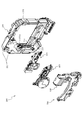
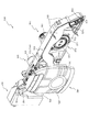
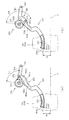
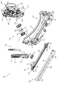
次いで、図16から図21を参照して、上下動作ユニット400について説明する。図16は、上下動作ユニット400の正面斜視図であり、図17は、上下動作ユニット400の背面斜視図である。なお、図16及び図17では、上下動作ユニット400のアーム部材440が退避位置に配置された状態が図示される。
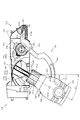
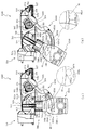
Next, the
図18は、上下動作ユニット400の正面分解斜視図であり、図19は、上下動作ユニット400の背面分解斜視図である。図18及び図19に示すように、上下動作ユニット400は、背面視右側に背面側から正面側へ向けて窪むと共にその窪みが上下方向に延設される上下溝部414を備えるベース部材410と、そのベース部材410の連結孔413を中心に回転される回転クランク部材420と、その回転クランク部材420の駆動力を発生させる駆動装置430と、回転クランク部材420から駆動力が伝達されベース部材410の軸部412を中心に揺動されるアーム部材440と、ベース部材410の上下溝部414の反対側に配設されアーム部材440の揺動に連動して上下方向にスライド移動可能に形成されるスライド部材450と、アーム部材440の先端に形成される摺動孔443に吊り下げられアーム部材440の揺動に連動して上下方向にスライド移動可能に形成されるレンズ部材460と、そのレンズ部材460にそれぞれ軸支される一対の扉部材470と、を主に備える。
18 is a front exploded perspective view of the
ベース部材410は、左右に長尺の板状に形成される本体部411と、その本体部411の右端部から正面側へ向けて円柱状に突設されアーム部材440の軸支孔442が軸支される軸部412と、前後方向に円形に穿設され回転クランク部材420と伝達ギア432が連結される連結孔413と、本体部411の背面視右側で背面側から正面側へ向けて形成される窪みが上下方向に延設される上下溝部414と、その上下溝部414の左右両外側において正面から背面側へ向けて窪む凹設部415と、を主に備える。
The
上下溝部414は、組立状態(図2参照)において、背面側に複合動作ユニット500の伸縮演出装置540が収容される部分である。複合動作ユニット500は、後述するように、伸縮演出装置540が縮小状態へ向かうほど伸縮演出装置540の揺動角度が抑制されるため、伸縮演出装置540が揺動されることで上下溝部414の左右内側面に衝突することが防止される。凹設部415は、スライド部材450のスライド案内部452が案内される部分である。
The upper and
回転クランク部材420は、板状の本体部421と、その本体部421の一方の端部から正面側に円柱状に突設されアーム部材440の挿通部444に挿通される摺動突起部422と、伝達ギア432の嵌合部432aに係合され伝達ギア432と回転クランク部材420との相対回転を不能とする係合部423と、を主に備える。
The rotating crank
摺動突起部422がアーム部材440の挿通部444に挿通され回転されることで、アーム部材440に駆動装置430の駆動力が伝達され、アーム部材440が軸部412を中心に揺動される。
When the sliding
駆動装置430は、ベース部材410に締結固定される上下用駆動モータ431と、その上下用駆動モータ431により回転駆動される駆動ギア431aと、その駆動ギア431aと歯合される伝達ギア432と、その伝達ギア432の正面側に連結孔413の内径より若干小さな外径で形成されると共に内側側面が回転クランク部材420の係合部423に嵌合される嵌合部432aと、を主に備える。
The
嵌合部432aは、三角形の各頂点に円形状が配置された断面形状からなる窪みを備える部分であって、ベース部材410の連結孔413に挿通されると共に、その先端側で回転クランク部材420の係合部423が相対回転不能に嵌合される。これにより、ベース部材410の本体部411を伝達ギア432と回転クランク部材420とで板挟みする態様で形成され、上述したように、伝達ギア432と回転クランク部材420の相対回転が不能とされるので、伝達ギア432と回転クランク部材420とは同期して回転する。即ち、上下用駆動モータ431の駆動力が伝達ギア432を介して回転クランク部材420へ伝達される。
The
アーム部材440は、長尺棒状に形成される本体部441と、基端側(正面視右側)に穿設され軸部412に揺動可能に軸支される軸支孔442と、基端側の反対側の端部である揺動端側に長孔として穿設されレンズ部材460の摺動突起部463が挿通される摺動孔443と、回転クランク部材420の摺動突起部422が挿通される有底孔状の挿通部444と、を主に備える。
The
なお、摺動突起部422を挿通部444に挿通させた状態で回転クランク部材420が一回転可能な形状に挿通部444の形状が設定される。そのため、回転クランク部材420の回転方向によらず、アーム部材440は揺動動作を行うことができる。
The shape of the
スライド部材450は、矩形板状の本体部451と、その本体部451の左右両端部から後方へ延設されると共に凹設部415に上下スライド可能に案内されるスライド案内部452と、本体部451の幅方向中心部において正面に形成される上下方向に延設される窪みであると共にレンズ部材460の摺動突起部463が挿通される中央案内凹設部453と、本体部451の左右両端部において正面に形成され上下方向に延設される窪みであると共にレンズ部材460の安定スライド部464が案内される両端案内凹設部454と、を主に備える。
The
レンズ部材460は、中央に円形の開口が形成される板状の本体部461と、その本体部461の開口に嵌め込まれる拡大レンズ加工が形成された拡大レンズ462と、本体部461の幅方向中央上端部において背面側へ突設されると共にアーム部材440の摺動孔443に上下スライド可能に挿通される摺動突起部463と、本体部461の幅方向両端部において背面側へ突設されスライド部材450の両端案内凹設部454に上下スライド可能に挿通される安定スライド部464と、本体部461の正面視左下方に軸回転可能に配設され扉部材470の下側軸部473及び上側軸部474が挿通される一対の回転筒465と、その一対の回転筒465を図示しない伝達機構により互いに逆方向に回転させる開閉用駆動モータ466と、を主に備える。
The
図20を参照して、上下動作ユニット400の移動動作について説明する。図20は、上下動作ユニット400の正面図である。なお、図20では、上下動作ユニット400のアーム部材440が張出位置へ配置された場合の扉部材470の閉鎖状態が図示される。
With reference to FIG. 20, the moving operation of the
アーム部材440が退避位置(図16参照)から張出位置(図20参照)へ揺動されると、アーム部材440の揺動端側の摺動孔443に軸支されるレンズ部材460の摺動突起部463(図18参照)が、スライド部材450の中央案内凹設部453をスライド移動される。レンズ部材460はスライド部材450の両端案内凹設部454に上下方向に案内され、スライド部材450はベース部材410の凹設部415に上下方向に案内されるので、アーム部材440の揺動によりレンズ部材460は上下方向にスライド移動される。
When the
図18及び図19に戻って説明する。扉部材470は、円形状板を上下2分割して構成され、下側に形成される下側本体部471と、その下側本体部471の上側に形成される上側本体部472と、下側本体部471の下端部において背面側に円柱状に突設されレンズ部材460の回転筒465に相対回転不能に挿通される下側軸部473と、上側本体部472の下端部において背面側に円柱状に突設されレンズ部材460の回転筒465に相対回転不能に挿通される上側軸部474と、を主に備える。
Returning to FIG. 18 and FIG. The
下側本体部471は、上側本体部472と当接される側の側面に突設される案内突起部471aを備え、上側本体部472は、下側本体部471と当接される側の側面に凹設される受け入れ凹設部472aを備える。これらの案内突起部471a及び受け入れ凹設部472aが嵌合されることで、閉鎖状態における下側本体部471と上側本体部472との相対的な位置合わせを行うことができる。なお、本実施形態では、案内突起部471aが先細り形状で突設されるので、案内突起部471aを受け入れ凹設部472aに確実に嵌合させることができる。
The lower
図21を参照して、扉部材470の動作について説明する。図21は、上下動作ユニット400の正面図である。なお、図21では、上下動作ユニット400のアーム部材440が張出位置へ配置された場合の扉部材470の開放状態が図示される。
The operation of the
下側軸部473及び上側軸部474(図19参照)は、レンズ部材460の回転筒465(図18参照)の回転により回転される。一対の回転筒465は、開閉用駆動モータ466(図19参照)の駆動力により互いに逆方向に回転されるので、扉部材470を、閉鎖状態(図20参照)から開放状態(図21参照)にする場合に、下側本体部471と上側本体部472とを互いに外側(反対方向)に揺動させることができる。また、扉部材470を、開放状態(図21参照)から閉鎖状態(図20参照)にする場合に、下側本体部471と上側本体部472とを互いに内側に揺動させることができる。
The
これにより、レンズ部材460の正面側を単一のカバー部材を揺動させて覆う場合に比較して、下側本体部471及び上側本体部472を揺動させる時間を半分とすることができる。
Thereby, compared with the case where a single cover member is swung to cover the front side of the
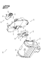
次いで、図22から図45を参照して、複合動作ユニット500について説明する。複合動作ユニット500は回動アーム部材550を退避位置(図22参照)から張出位置(図9参照)へ揺動させることで伸縮演出装置540を第3図柄表示装置81の正面側へ配置させるユニットである。また、伸縮演出装置540は、ベース部材510の第1軸部512(図24参照)を中心に揺動可能に形成される。
Next, the combined
図22は、複合動作ユニット500の正面斜視図であり、図23は、複合動作ユニット500の背面斜視図である。なお、図22及び図23では、回動アーム部材550が第3図柄表示装置81(図2参照)の外側に形成される終端位置である退避位置に配置される状態が図示される。
22 is a front perspective view of the combined
図24は、複合動作ユニット500の正面分解斜視図であり、図25は、複合動作ユニット500の背面分解斜視図である。
FIG. 24 is a front exploded perspective view of the
図24及び図25に示すように、複合動作ユニット500は、伸縮演出装置540をスライド動作および揺動動作させることで演出を行うユニットであり、骨格を形成するベース部材510と、そのベース部材510の第1軸部512を中心に回転可能に形成される回転板520と、ベース部材510に締結固定され回転板520の駆動力を発生させる第1駆動装置530と、回転板520の正面に締結固定され回転板520の径方向へ伸縮可能に形成される伸縮演出装置540と、その伸縮演出装置540に一方の端部が連結され反対側の他方の端部がベース部材510に軸支されると共に揺動動作により伸縮演出装置540の伸縮動作を形成する回動アーム部材550と、ベース部材510に締結固定され回動アーム部材550の駆動力を発生させる第2駆動装置560と、その第2駆動装置560の駆動力を回動アーム部材550へ伝達する回転クランク部材570と、ベース部材510の前方から締結固定され回動アーム部材550や回動クランク部材570等の回転軸側の機構部分を目隠しする前カバー580と、を主に備える。
As shown in FIGS. 24 and 25, the combined
ベース部材510は、矩形板形状の本体部511と、その本体部511の幅方向略中央下部から前方へ向けて突設される円柱状の第1軸部512と、その第1軸部512を中心とした円弧に沿って穿設される3列の円弧状孔513と、その3列の円弧状孔513の内の第2円弧状孔513bに隣接して穿設される第1貫通孔514と、軸部512と本体部511の右端部との略中間位置で本体部511から前方へ向けて突設される円柱状の第2軸部515と、その第2軸部515に隣接して穿設される第2貫通孔516と、本体部511の正面視右下端部から前方へ向けて突設される円柱状の第3軸部517と、本体部511の縁から前方へ折曲形成される折曲壁部518と、を主に備えて構成される。
The
第1軸部512は、回転板520の軸支孔522に挿通され、回転板520の回転軸となる部分である。そのため、第1軸部512の直径は回転板520の軸支孔522の内径よりも若干小さく形成される。
The
円弧状孔513は、第1軸部512に近い側から、第1円弧状孔513a、第2円弧状孔513b及び第3円弧状孔513cを備える。
The arc-shaped
第1円弧状孔513a及び第3円弧状孔513cは、回転板520の挿通軸525が挿通され、回転板520の回転を案内する長孔である。これにより、回転板520が回転される際に第1軸部512が受ける負荷を軽減することができ、回転板520の耐久性の向上を図ることができる。なお、図24及び図25には、挿通軸525の先端にカラーが締結された状態が図示されるが、第1円弧状孔513a及び第3円弧状孔513cは、カラーと本体部521との間に配置される(カラーの締結前に挿通される)。
The first arc-shaped
第2円弧状孔513bは、回転板520の円弧状ラック526が配置され移動される長孔である。略中央部の上側が開放され、その開放された部分に第1駆動装置530の駆動ギア532が配置される。これにより、本体部511の板厚部分に、第1駆動装置530の駆動モータ531と回転板520の円弧状ラック526との歯合部分を配設することができるので、複合動作ユニット500の厚さ方向の寸法(図22前後方向の寸法)を抑制することができる。
The second arc-shaped
第1貫通孔514及び第2貫通孔516は、それぞれ第1駆動装置530の駆動ギア532及び第2駆動装置560の駆動ギア562が挿通される貫通孔である。
The first through
第2軸部515は、正面側に回動クランク部材570の蓋部575が締結固定され、本体部571の回転の中心軸となる円柱状部である。そのため、第2軸部515の直径は回動クランク部材570の本体部571の内周径よりも若干小さな寸法で形成される。
The
第3軸部517は、回動アーム部材550の軸支孔552に挿通され、回動アーム部材550の回動の中心軸となる部分である。そのため、第3軸部517の直径は、回動アーム部材550の軸支孔552の内径よりも若干小さな寸法で形成される。第3軸部517の周囲には回動アーム部材550を退避位置へ向けて移動させる付勢力を発生させるねじりバネ517aが巻き付けられる。
The
ねじりバネ517aは、第3軸部517に巻き付けられるコイル部分の両端から腕部がそれぞれ延設される態様で形成される。一方の腕部は、折曲壁部518の正面視右下部(第1ストッパ部518a付近)に固定され、その一方の腕部の反対側の他方の腕部は、回動アーム部材550の係止部555に係止される。
The
折曲壁部518は、第3軸部517に隣接される第1ストッパ部518aと、第1軸部512の右方に形成される第2ストッパ部518bと、第1軸部512の左方に形成される第3ストッパ部518cと、を主に備える。
The
第1ストッパ部518aは、回動アーム部材550の回動を規制する部分である。即ち、回動アーム部材550は張出位置(図9参照)まで下降されると第1ストッパ部518aに当接され、下降が停止される。
The
図24に示すように、第2ストッパ部518bの方が第3ストッパ部518cよりも下方に配設される。回転板520の下面は軸支孔522を基準に左右対称に形成されるので(図37参照)、回転板520は、第2ストッパ部512bへ向かう回転方向の方が大きな回転角度で回転することができる。即ち、後述する伸縮演出装置540は、正面視反時計回りの揺動よりも、正面視時計回りの揺動の最大角度が大きく形成される。
As shown in FIG. 24, the
回転板520は、扇形板状の本体部521と、その本体部521の根本部分で厚み方向に円形に穿設される軸支孔522と、その軸支孔522の内径より若干大きな幅で本体部521の前面において直線的に凹設されるレール受け溝523と、そのレール受け溝523の下端部両側において前方へ張り出して形成される一対の伸縮ストッパ524と、本体部521の背面から突設される複数(本実施形態では3本)の挿通軸525と、本体部521の背面から軸支孔522を中心とする円弧状に突設され外周部にギア歯が刻設される円弧状ラック526と、を主に備える。
The
軸支孔522は、ベース部材510の第1軸部512が挿通される。そのため、回転板520は第1軸部512を中心に揺動される。
The
レール受け溝523は、伸縮演出装置540のスライドレール545が締結固定される部分であり、伸縮演出装置540はレール受け溝523の延設方向に沿って伸縮動作をする。そのため、回転板520の姿勢により、伸縮演出装置540の移動方向が変化される。
The
伸縮ストッパ524は、伸縮演出装置540のスライド板544の内側面に上下方向で当接され、スライド板544の移動幅を規制する部分である。レール受け溝523の両側に形成され、その両側においてスライド板544の内側面と当接されることで、スライドレール545が伸縮方向と直交する方向に負荷を受けることを抑制し、耐久性の向上を図ることができる。
The expansion /
挿通軸525は、ベース部材510の第1円弧状孔513a及び第3円弧状孔513cに挿通され回転板520の回転を案内する部分であって、直径が第1円弧状孔513a及び第3円弧状孔513cの幅寸法よりも若干小さく形成される。また、先端に第1円弧状孔513a及び第3円弧状孔513cの幅寸法よりも大径のカラー部材が締結固定されることで、回転板520がベース部材510に引き抜き不能に連結される。
The
円弧状ラック526は、ベース部材510の第2円弧状孔513bに挿通され、第1駆動装置530の駆動ギア532と歯合される。円弧状ラック526と第1駆動装置530との歯合部分がベース部材510の厚み部分を含んだ領域で形成されるので、複合動作ユニット500の厚み方向の寸法を抑制することができる。
The arc-shaped
第1駆動装置530は、ベース部材510に締結固定される駆動モータ531と、ベース部材510の第1貫通孔514に挿通され駆動モータ531により軸回転される駆動ギア532と、を主に備える。
The
次いで、図26及び図27を参照して伸縮演出装置540について説明する。図26は、伸縮演出装置540の正面分解斜視図であり、図27は、伸縮演出装置540の背面分解斜視図である。
Next, the expansion /
図26及び図27に示すように、伸縮演出装置540は、骨格を成す本体部材541と、その本体部材541の背面に一対が締結固定され本体部材541との間に回動アーム部材550の本体部551が挿通される第1案内部材542及び第2案内部材543と、その第1案内部材542及び第2案内部材543の挿通孔542d,543dの延設方向に沿って軸スライド可能に配設されるスライド板544と、そのスライド板544及び回転板520とを連結し一方の端部がレール受け溝523に内嵌され締結固定されるスライドレール545と、本体部材541の正面側に嵩上げされて締結固定される前板部材546と、その前板部材546の軸支部546cに摺動可能に軸支される連結摺動部材547と、その連結摺動部材547に締結固定されると共に前垂れ部548bが本体部材541の前方で移動可能に形成される装飾部材548と、を主に備える。
As shown in FIGS. 26 and 27, the expansion /
本体部材541は、骨格を形成する板状の本体部541aと、その本体部541aの幅方向中央部において背面側へ向けて突設される円柱状の突起部541bと、その突起部541bの背面視左側に上下一対で突設される第1嵩上げ締結部541cと、突起部541bの背面視右側に上下一対で突設される第2嵩上げ締結部541dと、本体部541aの背面視左上部に突設される案内締結部541eと、本体部541aの正面側に複数(本実施形態では3箇所)形成され前板部材546が締結固定される締結孔541fと、を主に備える。
The
突起部541bは、回動アーム部材550の円弧状孔554に挿通される部分である。そのため、突起部541bの直径は、円弧状孔554の内周面の幅寸法より若干小さく形成される。また、突起部541bが円弧状孔554に挿通されるので、回動アーム部材550を揺動させると、本体部材541を連動させることができる。
The protruding
第1嵩上げ締結部541cは、第1案内部材542を締結固定する部分であり、第2嵩上げ締結部541dは、第2案内部材543を締結固定する部分である。第1嵩上げ締結部541cよりも第2嵩上げ締結部541dの方が縦方向に離れる距離が長いのは、回動アーム部材550に干渉しない位置を選択して配設されるためである。ここで、本実施形態において、回動アーム部材は、その回動軌跡において、本体部材541の正面視左下方を通過しない(図37、図40及び図44参照)。そのため、一対の第2嵩上げ締結部541dの配設間隔を第1嵩上げ締結部541cに比較して広げることが可能となり、第2嵩上げ締結部541dの剛性を向上させることができる。
The first raised
案内締結部541eは、第1案内部材542の補助締結部542eが締結固定される部分であり、伸縮演出装置540の伸張状態において、回動アーム部材550の上面が案内される部分である。即ち、突起部541bが回動アーム部材550の円弧状孔554に案内されていなくとも、回動アーム部材550の上方への回動には案内締結部541eが回動アーム部材550の上面に案内されるので、回動アーム部材550と伸縮演出部材540とが連動して動作される。
The
締結孔541fは、前板部材546の締結部546bが締結固定される貫通孔である。
The
第1案内部材542は、第1嵩上げ締結部541cに締結固定される締結板部542aと、その締結板部542aの上面に背面側へ一段乗り上げた位置から上方向へ延設される背面規制部542bと、その背面規制部542bの左右両側から背面へ壁状に突設される案内レール部542cと、背面規制部542bの上端部において背面側へ突設された部分に上下方向へ貫通形成される挿通孔542dと、背面規制部542bから延設され案内締結部541eに締結固定される補助締結部542eと、を主に備える。
The
背面規制部542bは、回動アーム部材550の背面に配設される部分であって、回動アーム部材550が背面へ移動し円弧状孔554から突起部541bが脱落することを防止する部分である。
The back
案内レール部542cは、伸縮演出装置540が伸縮動作する場合にスライド板544のレール受け部544dの移動を案内し、スライド板544の第1案内部材542に対する姿勢のずれを抑制する部分である。
The
挿通孔542dは、スライド板544のスライド棒544eが挿通される孔である。挿通孔542dの内径はスライド棒544eの直径より若干大きく形成されるので、スライド板544は第1案内部材542に対してスライド移動可能に形成される。
The
第2案内部材543は、第2嵩上げ締結部541dに締結固定される締結板部543aと、その締結板部543aの上面に背面側へ一段乗り上げた位置から上方向へ延設される背面規制部543bと、その背面規制部543bの左右両側から背面へ壁状に突設される案内レール部543cと、背面規制部543bの上端部において背面側へ突設された部分に上下方向へ貫通形成される挿通孔543dと、を主に備える。
The
背面規制部543bは、回動アーム部材550の背面に配設される部分であって、回動アーム部材550が背面へ移動し円弧状孔554から突起部541bが脱落することを防止する部分である。
The back
案内レール部543cは、伸縮演出装置540が伸縮動作する場合にスライド板544のレール受け部544dの移動を案内し、スライド板544の第1案内部材543に対する姿勢のずれを抑制する部分である。
The
挿通孔543dは、スライド板544のスライド棒544eが挿通される孔である。挿通孔543dの内径はスライド棒544eの直径より若干大きく形成されるので、スライド板544は第1案内部材543に対してスライド移動可能に形成される。
The
スライド板544は、矩形板状に形成される本体部544aと、その本体部544aの背面において上下方向へ延設される幅広の窪みが形成される凹設部544bと、その凹設部544bの左右両側の正面において上下方向へ延設される窪みが形成される両端凹設部544cと、その両端凹設部544cの上下端部において正面側へ向けて半円状に突設されるレール受け部544dと、両端凹設部544cの内側で上下方向に延設される円柱状のスライド棒544eと、本体部544aの上下方向略中央に正面へ向けて突設される演出補助壁544fと、凹設部544bの上下端において左右両端で背面へ向けて突設されるストッパ部544gと、を主に備える。
The
凹設部544bは、回転板520の伸縮ストッパ524に対してスライド板544を案内する部分である。そのため、凹設部544bの内側面の幅は、伸縮ストッパ524の幅寸法よりも若干大きく形成される。
The recessed
両端凹設部544cは、案内部材542,543の挿通孔542d,543dが穿設される突起部を収容する部分である。これにより、案内部材542,543の挿通孔542d,543dが穿設される突起部を外側から案内することができる。
The both-end recessed
レール受け部544dは、案内部材542,543の案内レール部542c,543cに収容される部分である。これにより、案内部材542,543のスライド板544に対するぐらつきを抑制することができる。
The
スライド棒544eは、案内部材542,543の挿通孔542d,543dに挿通される円柱状の棒である。これにより、案内部材542,543はスライド棒544eの延設方向(図26上下方向)にスライド移動可能に形成される。
The
演出補助部544fは、伸縮演出装置540が伸張状態の時に装飾部材548の後ろ垂れ部548cに当接され、装飾部材548を移動させる部分である。これにより、伸縮演出装置540の外観を変化させることができる。
The
ストッパ部544gは、回転板520の伸縮ストッパ524に当接され、スライド板544の上下移動端を規定する部分である。
The
スライドレール545は、市販のミニレール部材である。一方の端部が回転板520のレール受け溝523に沿って締結固定され、その一方の端部の反対側の他方の端部がスライド板544の凹設部544bに締結固定される。
The
前板部材546は、遊技者から視認可能な演出部分であって、本体部材541と正面視において略同形状に形成される板状の本体部546aと、その本体部546aから背面側へ向けて締結孔541fの形成位置に合わせて突設される締結部546bと、本体部546aの上端部から背面側へ向けて突設される一対の軸支部546cと、を主に備える。
The
締結部546bは、本体部材541に前板部材546を固定する部分であって、締結孔541fを通してネジ止めすることで締結部546bが締結固定される。
The
軸支部546cは、連結摺動部材547を摺動可能に軸支する部分である。そのため、軸支部546cの直径は連結摺動部材547の摺動長孔547bの内周面の幅よりも若干小さく形成される。
The
連結摺動部材547は、板状に形成される本体部547aと、上下に延びる長孔状に形成され前後方向に穿設される一対の摺動長孔547bと、上下方向に穿設される一対の挿通孔547cと、を主に備える。
The connecting sliding
摺動長孔547bは、前板部材546の軸支部546cが挿通される部分である。そのため、摺動長孔547bの内周面の幅は軸支部546cより若干大きく形成される。摺動長孔547bの内周面の幅より外形の大きいカラー部材が軸支部546cの先端部に締結固定されることで、連結摺動部材547は、前板部材546に引き抜き不能に軸支される。挿通孔547cは、装飾部材548を締結固定する締結ネジが挿通される円形孔である。
The sliding
装飾部材548は、板状に形成され連結摺動部材547が下方から締結固定される本体部548aと、その本体部548aの前側で下方へ垂下して形成される前垂れ部548bと、本体部548aの後ろ側で下方へ垂下して形成される後ろ垂れ部548cと、を主に備える。
The
前垂れ部548bは、連結摺動部材547が前板部材546に対して移動すると、前板部材546に被さる状態(図43参照)と、前板部材546とは離間して視認される状態(図37参照)とを形成可能である。これにより、伸縮演出部材540の外観を変化させることができ、演出効果を向上させることができる。
When the connecting sliding
後ろ垂れ部548cは、伸縮演出装置540の伸縮動作によりスライド板544の演出補助壁544fに当接される部分であり、後ろ垂れ部548cが演出補助壁544fに当接されることで装飾部材548が前板部材546に対して移動される。
The back
図24及び図25に戻って説明する。回動アーム部材550は、長尺に棒状に形成される本体部551と、その本体部551の一方の端部に前後方向に穿設される軸支孔552と、その軸支孔552に近接して本体部551の背面側に形成される特殊形状の有底長孔である異形長孔553と、一方の端部の反対側の端部である他方の端部の正面側に形成される円弧状の有底長孔である円弧状孔554と、本体部551の軸支孔552付近において背面側へ突設され先端が鉤状に折り曲げられると共にねじりバネ517aの他方の腕部が係止される係止部555と、を主に備える。
Returning to FIG. 24 and FIG. The
軸支孔552は、ベース部材510の第3軸部517が挿通される円形孔である。そのため、軸支孔552の内径は、第3軸部517の直径より若干大きく形成され、それにより回動アーム部材550が第3軸部517を中心に回動可能に形成される。
The
異形長孔553は、回動クランク部材570の摺動突起部574が挿通される部分である。異形長孔553の形状については後述する。
The odd-shaped
円弧状孔554は、伸縮演出装置540の突起部541bが挿通される長孔である。そのため、円弧状孔554の幅寸法は突起部541bの直径より若干大きく形成される。また、円弧状孔554の形成する円弧は、伸縮演出装置540が伸張状態で第1軸部512を中心に揺動された場合に突起部541bが形成する円弧と一致する(図37から図39まで参照)。
The arc-shaped
また、円弧状孔554は、回転アーム部材550の他方の端部の先端部に開放され、先端部において幅が広がる口先部554aを備える。
The arc-shaped
第2駆動装置560は、回動クランク部材570を回転させる駆動力を発生させる装置であって、ベース部材510に締結固定される駆動モータ561と、ベース部材510の第2貫通孔516に挿通され駆動モータ561により軸回転される駆動ギア562と、を主に備える。
The
駆動ギア562は、回動クランク部材570の伝達ギア歯572に歯合される。これにより、駆動ギア562が回転されると、それに伴い回動クランク部材570が回転される。
The
回動クランク部材570は、回動アーム部材550に駆動力を伝達する部材であって、第2軸部515に軸支されるリング状の本体部571と、その本体部571の外周面に刻設される伝達ギア歯572と、その伝達ギア歯572の正面側に被さる態様で形成される規制傘部573と、本体部571の中心とは偏心した位置で正面側に突設される摺動突起部574と、本体部571の内周径よりも大きな直径で形成され第2軸部515の正面側に締結固定される蓋部575と、を主に備える。
The rotating crank
伝達ギア歯572は、第2駆動装置560の駆動ギア562と歯合される。これにより、駆動モータ561の駆動力が回動クランク部材570に伝達される。
The
規制傘部573は、駆動ギア532が伝達ギア歯572の正面側に位置ずれすることを抑制する。これにより、駆動ギア532と伝達ギア歯572との歯合関係を適正化することができる。
The restricting
摺動突起部574は、回動アーム部材550の異形長孔553に挿通される部分である。即ち、摺動突起部574と回動アーム部材550の形状との関係により、駆動力の伝達が形成されるか否かが決定される。
The sliding
蓋部575は、本体部571をベース部材510に引き抜き不能に配設するための部分である。
The
図28から図31を参照して、回動アーム部材550の揺動と回動クランク部材570の回転との関係について説明する。まず、図28(a)及び図29(a)を参照して、回動アーム部材550の異形長孔553の形状について説明する。
With reference to FIGS. 28 to 31, the relationship between the swing of the
図28(a)及び図29(a)は、回動アーム部材550及び回動クランク部材570の正面図である。なお、図28(a)では、回動アーム部材550が退避位置に配置された状態が図示され、図29(a)では、回動アーム部材550が張出位置に配置された状態が図示され、図28(a)及び図29(a)において、異形長孔553と摺動突起部574とが隠れ線で図示されると共に伸縮演出装置540の前板部材546及び突起部541bが想像線で図示される。
FIGS. 28A and 29A are front views of the
図28(a)に示すように、回動アーム部材550が退避位置に配置された状態において、回動クランク部材570の回転軸および摺動突起部574を結ぶ直線と、回動クランク部材570の回転軸および軸支孔552を結ぶ直線と、が直交される上向き直交状態が形成される。
As shown in FIG. 28A, in a state where the
図29(a)に示すように、回動アーム部材550が張出位置に配置された状態において、回動クランク部材570の回転軸および摺動突起部574を結ぶ直線と、回動クランク部材570の回転軸および軸支孔552を結ぶ直線と、が直交される下向き直交状態を形成可能とされる。なお、図29(a)では、上述した下向き直交状態から回動クランク部材570が正面視反時計回りに所定角度回転された状態が図示される。
As shown in FIG. 29A, in a state where the
異形長孔553は、摺動突起部574が移動することで駆動力が回動アーム部材550に伝達される伝達溝部553aと、その伝達溝部553aの上端部から連結される第1非伝達壁部553bと伝達溝部553aの下端部から連結される第2非伝達壁部553cと、それら第1非伝達壁部553bと第2非伝達壁部553cとを連結する選択壁部553dと、を主に備える。
The deformed
伝達溝部553aは、図28(a)に示すように、上向き直交状態において回動クランク部材570の摺動突起部574を起点として、左方に直線的に延設される凹設溝である。伝達溝部553aは、回転クランク部材570の摺動突起部574が上向き直交状態から下向き直交状態へ移動可能な長さで形成され、その内周面の形成幅は摺動突起部574の直径より若干大きく形成される。そのため、摺動突起部574が伝達溝部553aを移動する間、回動クランク部材570から駆動力が回動アーム部材550へ伝達される。
As shown in FIG. 28A, the
第1非伝達壁部553bは、図28(a)に示すように、上向き直交状態において、伝達溝部553aの右端部の上側壁面から、回動クランク部材570の回転軸を中心とした摺動突起部574の外接円に沿って形成される壁部である。即ち、上向き直交状態から回転クランク部材570が正面視時計回りに回転される場合、回動クランク部材570が回動アーム部材550に対して空回りし、回動クランク部材570から駆動力は回動アーム部材550へ伝達されない。
As shown in FIG. 28A, the first
なお、回動アーム部材550が退避位置に配置された状態(図28(a)参照)から回動アーム部材550が正面視反時計回りに回転されるとき、第1非伝達壁部553bの移動方向は回動クランク部材570の回転軸へ向けられる。そのため、摺動突起部574が第1非伝達壁部553bと対向配置される場合、回動アーム部材550が回転されることで摺動突起部574へ与えられる負荷は回動クランク部材570の回転軸へ向けられる。そのため、摺動突起部574が第1非伝達壁部553bに対向配置される場合、回動アーム部材550の回転が防止される。
When the
第2非伝達壁部553cは、図29(a)に示すように、回動アーム部材550が張出位置に配置された状態において、伝達溝部553aの右端部の下側壁面から、回動クランク部材570の回転軸を中心とした摺動突起部574の外接円に沿って形成される壁部である。即ち、下向き直交状態(図29(a)の状態から回動クランク部材570が正面視時計回りに所定量回転された状態)から回動クランク部材570が正面視反時計回りに回転される場合、回動クランク部材570が回動アーム部材550に対して空回りし、回動クランク部材570から駆動力は回動アーム部材550へ伝達されない。
As shown in FIG. 29 (a), the second
なお、図29(a)に図示される状態から回動アーム部材550が正面視時計回りに回転されるとき、第2非伝達壁部553bの移動方向は回動クランク部材570の回転軸へ向けられる。そのため、摺動突起部574が第2非伝達壁部553cと対向配置される場合(図29(b)参照)、回動アーム部材550が回転されることで摺動突起部574へ与えられる負荷は回動クランク部材570の回転軸へ向けられる。そのため、摺動突起部574が第2非伝達壁部553cに対向配置される場合、回動アーム部材550の回転が防止される。
Note that when the
選択壁部553dは、第1非伝達壁部553bの正面視右端部と、第2非伝達壁部553cの正面視右端部とを結ぶ滑らかな曲面から形成される壁部であり、第1非伝達壁部553bを延長させた曲線よりも上側に形成される。
The
選択壁部553dは、第2非伝達壁部553cの右側部分と対向配置され、選択壁部553dの左端部へ向かうほど第2非伝達壁部553cとの距離が離される態様で形成される。そのため、例えば上向き直交状態(図28(a)参照)から、回動クランク部材570を正面視時計回りに回転させる場合、摺動突起部574が第1非伝達壁部553bを越え第2非伝達壁部553cに到達するまでの間の余裕部D(図32(b)参照)では、回動アーム部材550には駆動力が伝達されず、かつ回転の規制も生じない。即ち、回動クランク部材570から回動アーム部材550へ駆動力が伝達されず、かつ摺動突起部574による回動アーム部材550の回転の規制も生じない。
The
第2非伝達壁部553cの右端部は、軸支孔552を中心とした円弧S1に沿って形成される(円弧S1との形成角度が小さい)一方で、選択壁部553dの右端部は、第2非伝達壁部553cの右端部と円弧S1との形成角度よりも大きな角度で軸支孔552を中心とした円弧S2と交差する態様で形成される。
The right end portion of the second
この場合、摺動突起部574と軸支孔552との距離が変化する場合に、その変化量に対応するため必要となる回動アーム部材550の揺動量が変化する。即ち、摺動突起部574と選択壁部553dの右端部が当接した状態で摺動突起部574と軸支孔552との間隔が所定量変化する場合の回動アーム部材550の揺動量は、摺動突起部574と第2非伝達壁部553cの右端部が当接した状態で所定量変化する場合の回動アーム部材550の揺動量に比較して小さくなる。従って、摺動突起部574が第2非伝達壁部553cに沿って回転するか、選択壁部553dに沿って回転するかで、回動クランク部材570の速度に対する回動アーム部材550の揺動速度を変化させることができる。
In this case, when the distance between the sliding
図28から図31に戻って説明する。図28から図31は、回動アーム部材550の揺動および回動クランク部材570の回転を時系列で図示した回動アーム部材550及び回動クランク部材570の正面図である。なお、図28(a)では、上述した上向き直交状態が形成され(回動アーム部材550が退避位置に配置され)、図28から図31では、回動クランク部材570が正面視反時計回りに回転される状態が順に図示され、異形長孔553と回動クランク部材570の一部とが隠れ線で図示されると共に伸縮演出装置540の前板部材546及び突起部541bが想像線で図示される。
Returning to FIG. FIGS. 28 to 31 are front views of the
なお、図28から図31までにおいて、伸縮演出装置540は上下方向に伸縮する姿勢を位置検出センサ(図示せず)で検出され、その姿勢で揺動を停止される。即ち、図28から図31までにおいて、突起部541bは上下方向にのみ移動する。この場合、伸縮演出装置540の揺動は第1駆動装置530(図25参照)の駆動ギア532との間の抵抗により防止される。
28 to 31, the expansion /
図28(a)の状態では、回動クランク部材570が上向き直交状態とされる。この場合において、突起部541bから鉛直下方に距離h1だけ下がった位置に基準水平線Oを設定する。即ち、回動クランク部材570が上向き直交状態とされる場合、突起部541bは基準水平線Oから鉛直上方に距離h1だけ離間した位置に配置される。
In the state of FIG. 28A, the rotating crank
図28(a)の状態から、回動クランク部材570が正面視反時計回りに回転される(上向き直交状態(図28(a)参照)から反時計回りに角度T1だけ回転される)と、摺動突起部574が異形長孔553の伝達溝部553aを移動され、突起部541が基準水平線Oから鉛直上方に距離h2(h2<h1)だけ離間した位置に配置される状態(図28(b)参照)に到達する。この間、摺動突起部574の移動方向に異形長孔553の内周面が配置され互いに当接されるので、摺動突起部574から回動アーム部材550へ駆動力が伝達される(伝達領域)。即ち、回動アーム部材550が揺動される。
From the state of FIG. 28 (a), the rotating crank
図28(b)の状態から、回動クランク部材570が正面視反時計回りに回転される(上向き直交状態(図28(a)参照)から反時計回りに角度T2(T2≒180度>T1)だけ回転される)と、摺動突起部574が異形長孔553の伝達溝部553aを移動され(伝達領域)、第2非伝達壁部553cに対面する領域に侵入し、突起部541が基準水平線Oから鉛直上方に距離h3(h3<h2)だけ離間した位置に配置される状態(図29(a)参照)の状態に到達する。即ち、回動アーム部材550が揺動される。
From the state of FIG. 28 (b), the rotating crank
図28(c)の状態から、回動クランク部材570が正面視反時計回りに回転される(上向き直交状態(図28(a)参照)から反時計回りに角度T3(T3>T2)だけ回転される)と、摺動突起部574が異形長孔553の第2非伝達壁部553cに摺動され、図29(b)の状態に到達する。この間、摺動突起部574の移動方向に異形長孔553の内周面が配置されないので、摺動突起部574は回動アーム部材550に対して空転され、摺動突起部574から回動アーム部材550へ駆動力が伝達されず(非伝達領域)、突起部541は基準水平線Oから鉛直上方へ距離h3だけ離間した位置に維持される。
From the state of FIG. 28C, the rotating crank
なお、図29(a)及び図29(b)の状態から回動アーム部材550を正面視時計回りに回転させる場合、摺動突起部574が回動クランク部材570の回転軸へ向けて第2非伝達壁部553cにより押される。この場合、摺動突起部574は移動を規制され、それにより、回動アーム部材550の揺動が規制される。そのため、回動アーム部材550は、図29(a)及び図29(b)の状態からの正面視時計回りの回転を防止される。
29A and 29B, when the
ここで、回動アーム部材550の回転を図29(a)の状態で停止させる方法としては、回動クランク部材570を停止させることが考えられる。しかし、回動アーム部材550の演出速度を張出位置へ到達する直前まで高速とし回動クランク部材570を急停止させると第2駆動装置560に負荷がかかり、回動クランク部材570の速度低下を緩やかにすると演出効果を向上させることができなくなる。
Here, as a method of stopping the rotation of the
一方、本実施形態では、図28及び図29に示すように、回動クランク部材570を図29(a)の状態で停止させず図29(b)の状態まで回転させることで、回動アーム部材550の回転を図29(a)の状態で停止させることができる(突起部541を基準水平線Oから鉛直上方へ距離h3だけ離間した位置に停止させることができる)。これにより、回動アーム部材550を張出位置に到達させるまで回動クランク部材570の速度を維持し、その後、図29(a)の状態から図29(b)の状態までに回動クランク部材570を減速させることができる。そのため、回動クランク部材570を急停止させる必要がない。従って、回動アーム部材550の演出効果の向上と、第2駆動装置560の耐久性の向上との両立を図ることができる。
On the other hand, in the present embodiment, as shown in FIGS. 28 and 29, the rotating crank
図29(b)の状態から、回動クランク部材570が正面視反時計回りに回転される(上向き直交状態(図28(a)参照)から反時計回りに角度T4(T4≒270度>T3)だけ回転される)と、摺動突起部574が異形長孔553の第2非伝達壁部553cに摺動され、図30(a)の状態に到達する。この間、摺動突起部574の移動方向に異形長孔553の内周面が配置されないので、摺動突起部574は回動アーム部材550に対して空転され、摺動突起部574から回動アーム部材550へ駆動力が伝達されず(非伝達領域)、突起部541は基準水平線Oから鉛直上方へ距離h3だけ離間した位置に維持される。
From the state of FIG. 29B, the rotating crank
即ち、回動クランク部材570が図29(a)に示す状態から、反時計回りに1/4周回転される間、回動アーム部材550が同じ姿勢に維持され、突起部541bが同じ位置に維持される。なお、回動アーム部材550が同じ姿勢に維持され、突起部541bが同じ位置に維持される長さは本実施形態では回動クランク部材570が1/4周回転される間とされたが、それに限定される必要はない。前板部材546が下方位置に配置され続ける長さは、異形長孔553の第2非伝達壁部553c(図28(a)参照)の長さを変えることで変化させることができる。例えば、第2非伝達壁部553cを本実施形態より長くすることで、前板部材546が下方位置に配置され続ける長さを本実施形態より長くすることができる。
That is, while the rotating crank
図30(a)の状態から、回動クランク部材570が正面視反時計回りに回転される(上向き直交状態(図28(a)参照)から反時計回りに角度T5(T5>T4)だけ回転される)と、摺動突起部574が異形長孔553の選択壁部553dを押し上げ、突起部541が基準水平線Oから鉛直上方に距離h2(h2>h3)だけ離間した位置に配置される状態(図30(b)参照)に到達する。この間、摺動突起部574の移動方向に異形長孔553の内周面が配置され互いに当接されるので、摺動突起部574から回動アーム部材550へ駆動力が伝達される(伝達領域)。
From the state of FIG. 30A, the rotating crank
即ち、回動アーム部材550及び回動クランク部材570が正面視反時計回りに回転される場合には、選択壁部553dと摺動突起部574とが当接されることで、回動アーム部材550へ駆動力が伝達される(伝達領域)。
That is, when the turning
図30(b)の状態から、回動クランク部材570が正面視反時計回りに回転される(上向き直交状態(図28(a)参照)から反時計回りに角度T6(T6>T5)だけ回転される)と、摺動突起部574が異形長孔553の第1非伝達壁部553bに対面する領域に侵入し、突起部541が基準水平線Oから鉛直上方に距離h1(h1>h2)だけ離間した位置に配置される状態(図31参照)に到達する。この間、摺動突起部574の移動方向に異形長孔553の内周面が配置され互いに当接されるので、摺動突起部574から回動アーム部材550へ駆動力が伝達される(伝達領域)。
From the state of FIG. 30 (b), the rotating crank
図31の状態から、回動クランク部材570が正面視反時計回りに回転されると、摺動突起部574が異形長孔553の第1非伝達壁部553bに対面する領域を移動され、図28(a)の状態に到達する。この間、摺動突起部574の移動方向に異形長孔553の内周面が配置されないので、摺動突起部574は回動アーム部材550に対して空転され、摺動突起部574から回動アーム部材550へ駆動力が伝達されない(非伝達領域)。
31, when the rotating crank
なお、図31の状態から回動アーム部材550を正面視反時計回りに回転させる場合、摺動突起部574が回動クランク部材570の回転軸へ向けて第2非伝達壁部553cにより押される。この場合、摺動突起部574は移動を規制され、それにより、回動アーム部材550の揺動が規制される。そのため、回動アーム部材550は、図31の状態からの正面視反時計回りの回転を防止される。
When the
ここで、回動アーム部材550の回転を図31の状態で停止させる方法としては、回動クランク部材570を停止させることが考えられる。しかし、回動アーム部材550の演出速度を退避位置へ到達する直前まで高速とし回動クランク部材570を急停止させると第2駆動装置560に負荷がかかり、回動クランク部材570の速度低下を緩やかにすると演出効果を向上させることができなくなる。
Here, as a method of stopping the rotation of the
一方、本実施形態では、回動クランク部材570を図31の状態で停止させず図28(a)の状態まで回転させることで、回動アーム部材550の回転を図31の状態で停止させることができる。これにより、回動アーム部材550を張出位置に到達させるまで回動クランク部材570の速度を維持し、その後、図31の状態から図28(a)の状態までに回動クランク部材570を減速させることができる。そのため、回動クランク部材570を急停止させる必要がない。従って、回動アーム部材550に連動される伸縮演出装置540の演出効果の向上と、第2駆動装置560の耐久性の向上との両立を図ることができる。
On the other hand, in this embodiment, the rotation of the
図28から図31に示すように、回動クランク部材570を同じ方向へ1回転させることで、回動アーム部材550を退避位置から張出位置の間を往復で揺動させることができる。
As shown in FIGS. 28 to 31, by rotating the rotating crank
これらのことから、図28から図31に示すように回動クランク部材570を反時計回りに等速で回転させる場合、回動クランク部材570の回転周期の半分の期間で突起部541bが基準水平線Oから鉛直上方に距離h1だけ離間した位置から、距離h3(h3<h1)だけ離間した位置まで下降移動される。それに続く回転周期の1/4の期間で突起部541bが基準水平線Oから鉛直上方に距離h3だけ離間した位置に維持され、それに続く回転周期の1/4の期間で突起部541bが基準水平線Oから鉛直上方に距離h3だけ離間した位置から、距離h1(h1>h3)だけ離間した位置まで上昇移動される。これにより、回動クランク部材570が等速で移動される場合であっても突起部541bの移動速度(伸縮演出装置540の伸縮方向への移動速度)を2倍に変化させることができる。
For these reasons, when the rotating crank
ここで、回動アーム部材550の退避位置において、回動アーム部材550及び回動クランク部材570は上向き直交状態を形成可能とされ(図28(a)参照)、回動アーム部材550の張出位置において、回動アーム部材550及び回動クランク部材570は下向き直交状態を形成可能とされる(図29(a)参照)。なお、図29(a)の状態から、回動クランク部材570を正面視時計回りに所定量回転させることで下向き直交状態を形成可能である。
Here, at the retracted position of the
そのため、本実施形態において、回動アーム部材550を退避位置から張出位置に揺動させるために、回動クランク部材570が半周(180度)回転される。そのため、回動クランク部材570が等速で回転される場合、回動アーム部材550が退避位置から張出位置まで揺動されるのに要する時間(図28(a)から図29(a)まで参照)と、張出位置から退避位置まで揺動されるのに要する時間(図29(a)から図31を経て図28(a)まで参照)とを同等にすることができる。
Therefore, in this embodiment, the rotating crank
図32から図35を参照して、回動アーム部材550の揺動と回動クランク部材570の回転との関係について説明する。図32から図35は、回動アーム部材550の揺動および回動クランク部材570の回転を時系列で図示した回動アーム部材550及び回動クランク部材570の正面図である。なお、図32から図35では、回動クランク部材570が正面視時計回りに回転される状態が図示され、異形長孔553と回動クランク部材570の一部とが隠れ線で図示されると共に伸縮演出装置540の前板部材546及び突起部541bが想像線で図示される。
With reference to FIGS. 32 to 35, the relationship between the swinging of the
なお、図32(a)では、上述した上向き直交状態が形成され(回動アーム部材550が退避位置に配置され)、図32(b)から図35では、図32(a)から回動アーム部材550及び回動クランク部材570が所定量回転された状態が時系列に沿って順に図示される。
32A, the above-described upward orthogonal state is formed (the
図32(a)の状態では、回動クランク部材570が上向き直交状態とされる。この場合において、突起部541bは基準水平線Oから鉛直上方に距離h1だけ離間した位置に配置される。
In the state of FIG. 32A, the rotating crank
図32(a)の状態から、回動クランク部材570が正面視時計回りに回転される(上向き直交状態(図32(a)参照)から時計回りに角度T11だけ回転される)と、摺動突起部574が異形長孔553の第1非伝達壁部553bに対面する領域を移動され、図32(b)の状態に到達する。この間、摺動突起部574の移動方向に異形長孔553の内周面が配置されないので、摺動突起部574は回動アーム部材550に対して空転され、摺動突起部574から回動アーム部材550へ駆動力が伝達されず(非伝達領域)、突起部541は基準水平線Oから鉛直上方へ距離h1だけ離間した位置に維持される。
From the state of FIG. 32 (a), the rotating crank
なお、図32(b)の状態から回動アーム部材550を正面視反時計回りに回転させる場合、摺動突起部574は移動を規制されるので、回動アーム部材550の揺動が規制される。そのため、回動アーム部材550は、図32(b)の状態からの正面視反時計回りの回転を防止される。
Note that, when the
図32(b)の状態から、回動クランク部材570が正面視時計回りに回転される(上向き直交状態(図32(a)参照)から時計回りに角度T12(T12>T11)だけ回転される)と、図33(a)に示すように、摺動突起部574が異形長孔553の内周面と若干離間され、回動アーム部材550は重力の作用により下方へ揺動される。この場合、図32(b)の状態から摺動突起部574が第1非伝達壁部553bを越え第2非伝達壁部553cに到達するまでの間の余裕部Dでは、回動アーム部材550には駆動力が伝達されず(非伝達領域)、突起部541は基準水平線Oから鉛直上方へ距離h4(h4<h1)だけ離間した位置に配置される。
From the state of FIG. 32 (b), the rotating crank
図33(a)の状態から、回動クランク部材570が正面視時計回りに回転される(上向き直交状態(図32(a)参照)から時計回りに角度T13(T13>T12)だけ回転される)と、図33(b)に示すように、重力の作用で下方へ揺動する回動アーム部材550の異形長孔553の第2非伝達壁部553cに摺動突起部574が当接される。即ち、図33(b)の状態から、図34(a)の状態までは、回動アーム部材550に駆動力が伝達される(伝達領域)。図33(b)の状態では、突起部541は基準水平線Oから鉛直上方へ距離h5(h5<h4)だけ離間した位置に配置される。
From the state shown in FIG. 33 (a), the rotating crank
図33(b)の状態から、回動クランク部材570が正面視時計回りに回転される(上向き直交状態(図32(a)参照)から時計回りに角度T14(T14≒90度>T13)だけ回転される)と、摺動突起部574が異形長孔553の第2非伝達壁部553cの右端部に収容され、突起部541が基準水平線Oから鉛直上方に距離h3だけ離間した位置に配置される状態(図34(a)参照)に到達する。この間、摺動突起部574の移動方向に異形長孔553の内周面が当接され、回動アーム部材550へ駆動力が伝達される(伝達領域)。
From the state of FIG. 33 (b), the rotating crank
ここで、図32(b)から図34(a)までに示される回動クランク部材570の回転と、図30(a)から図31までに示される回動クランク部材570の回転とは、回動クランク部材570の回転方向が異なるが、回動クランク部材570の回転領域(位相)は同じである。
Here, the rotation of the rotating crank
この場合に、図32(b)から図34(a)までに示される回動クランク部材570の回転では、回動クランク部材570の摺動突起部574の移動方向に異形長孔553の内周面が当接されない間は回動アーム部材550に駆動力が伝達されず(非伝達領域)、一方で、図30(a)から図31までに示される回動クランク部材570の回転では、常時、回動アーム部材550に駆動力が伝達される(伝達領域)。
In this case, in the rotation of the rotating crank
従って、回動クランク部材570の回転方向により、回動アーム部材550への駆動力の伝達の態様を変化させることができる。これにより、回動クランク部材570の回転方向を反転させることで、回動アーム部材550の演出態様を2通り形成することができる。
Therefore, the mode of transmission of the driving force to the
即ち、本実施形態では、回動クランク部材570の摺動突起部574が図32(a)と図34(a)との間を回転する場合に、回動クランク部材570が正面視時計回りに回転されると、回動アーム部材550は、摺動突起部574が異形長孔553の内周面と当接するまでは、重力加速度に依存した自由落下で揺動される(非伝達領域)。一方で、回動クランク部材570が正面視反時計回りに回転されると、回動アーム部材550は回転クランク部材570の回転速度に依存した速度で揺動される(伝達領域)。
That is, in this embodiment, when the sliding
これにより、回動クランク部材570の回転速度が等速とされる場合でも、回動クランク部材570の回転方向を反転させることで、回動クランク部材570が同一位相に配置される場合の回動アーム部材550の揺動速度のバリエーションを増やすことができる。
Thereby, even when the rotation speed of the rotation crank
また、回動アーム部材550の揺動速度のバリエーションの増加は、異形長孔553の形状(余裕部Dの形成)により達成されるので、回動アーム部材550への駆動力の伝達の態様を変化させるための切換スイッチなど他の部材を不要とでき、部材コストを低減することができる。
Further, the increase in the variation of the swinging speed of the
本実施形態では、余裕部Dが回動アーム部材550の軸支孔552側に形成される。そのため、余裕部Dが回動クランク部材570の回転軸に対して軸支孔552の反対側に形成される場合に比較して、摺動突起部574が余裕部Dを所定距離通過する間に突起部541bが下方へ移動する距離を長くすることができる。そのため、回動クランク部材570の余裕部Dの形成範囲を抑制しつつ、回動クランク部材570の回転方向を異ならせた場合の回動アーム部材550の動作の変化を顕著にすることができる。
In the present embodiment, the margin portion D is formed on the
図34(a)の状態から、回動クランク部材570が正面視時計回りに回転される(上向き直交状態(図32(a)参照)から時計回りに角度T15(T15>T14)だけ回転される)と、摺動突起部574が異形長孔553の第2非伝達壁部553cに摺動され、図34(b)の状態に到達する。この間、摺動突起部574の移動方向に異形長孔553の内周面が配置されないので、摺動突起部574は回動アーム部材550に対して空転され、摺動突起部574から回動アーム部材550へ駆動力が伝達されず(非伝達領域)、突起部541は基準水平線Oから鉛直上方へ距離h3だけ離間した位置に維持される。
From the state of FIG. 34 (a), the rotating crank
なお、図34(b)の状態から回動アーム部材550を正面視時計回りに回転させる場合、摺動突起部574が回動クランク部材570の回転軸へ向けて第2非伝達壁部553cにより押される。この場合、摺動突起部574は移動を規制されるので、回動アーム部材550の揺動が規制される。そのため、回動アーム部材550は、図34(b)の状態からの正面視時計回りの回転を防止される。
When the
図34(b)の状態から、回動クランク部材570が正面視時計回りに回転される(上向き直交状態(図32(a)参照)から時計回りに角度T16(T16≒180度>T15)だけ回転される)と、摺動突起部574が異形長孔553の第2非伝達壁部553cに摺動され、図35(a)の状態に到達する。この間、摺動突起部574の移動方向に異形長孔553の内周面が配置されないので、摺動突起部574は回動アーム部材550に対して空転され、摺動突起部574から回動アーム部材550へ駆動力が伝達されず(非伝達領域)、突起部541は基準水平線Oから鉛直上方へ距離h3だけ離間した位置に維持される。
From the state of FIG. 34 (b), the rotating crank
図35(a)の状態から、回動クランク部材570が正面視時計回りに回転される(上向き直交状態(図32(a)参照)から時計回りに角度T17(T17>T16)だけ回転される)と、摺動突起部574が伝達溝部553aを移動され(伝達領域)、突起部541が基準水平線Oから鉛直上方に距離h2(h2>h3)だけ離間した位置に配置される状態(図35(b)参照)に到達する。即ち、回動アーム部材550が揺動される。
From the state of FIG. 35 (a), the rotating crank
ここで、回動クランク部材570の回転と回動アーム部材550の揺動とが常時連動する場合、回動クランク部材570と回動アーム部材550との始動のタイミングをずらすことが困難であった。そのため、回動クランク部材570と回動アーム部材550とを始動させる際には、各部材の慣性に打ち勝つ力の剛性分の大きな力を発生させることが必要となる。そのため、駆動力の大きな駆動装置が必要となり、駆動装置が大型化する恐れがあった。
Here, when the rotation of the rotation crank
一方、本実施形態では、回動クランク部材570と回動アーム部材550との始動のタイミングをずらすことができる。即ち、例えば、図34(b)の状態から図35(a)の状態までは回動クランク部材570のみを回転させ、図35(a)の状態から図35(b)の状態に到達するまでに回動クランク部材570に連動させることで回動アーム部材550を始動させることができる。
On the other hand, in this embodiment, the starting timing of the rotating crank
これにより、回動アーム部材550の始動には回動クランク部材570の勢いを利用することができるので、第2駆動装置560に必要な駆動力を抑制することができる。従って、第2駆動装置560を小型化することができる。
Thereby, since the momentum of the rotating crank
図35(b)の状態から、回動クランク部材570が正面視時計回りに回転されると、摺動突起部574が伝達溝部553aを移動され、図32(a)の状態に到達する。この間、摺動突起部574の移動方向に異形長孔553の内周面が配置され互いに当接されるので、摺動突起部574から回動アーム部材550へ駆動力が伝達される(伝達領域)。即ち、回動アーム部材550が揺動される。
When the rotating crank
これらのことから、図32から図35に示すように回動クランク部材570を時計回りに等速で回転させる場合、回動クランク部材570の回転周期の1/4の期間で突起部541bが基準水平線Oから鉛直上方に距離h1だけ離間した位置から、距離h3(h3<h1)だけ離間した位置まで下降移動される。それに続く回転周期の1/4の期間で突起部541bが基準水平線Oから鉛直上方に距離h3だけ離間した位置に維持され、それに続く回転周期の半分の期間で突起部541bが基準水平線Oから鉛直上方に距離h3だけ離間した位置から、距離h1(h1>h3)だけ離間した位置まで上昇移動される。これにより、回動クランク部材570が等速で移動される場合であっても突起部541bの移動速度(伸縮演出装置540の伸縮方向への移動速度)を2倍に変化させることができる。
For these reasons, when the rotating crank
また、回動アーム部材550の移動速度は、下降移動する場合は部分的に重力加速度で増速され、その一方で、上昇移動する場合は常時回動クランク部材570の回転速度に沿った速度とされる。これにより、突起部541b(伸縮演出装置540)の速度変化の態様を突起部541b(伸縮演出装置540)の移動の向きにより変化させることができる。
Further, the moving speed of the
図36を参照して、回動クランク部材570が時計回り又は反時計回りに回転される場合の突起部541b(伸縮演出装置540)の基準水平線Oからの距離の変化について説明する。
With reference to FIG. 36, a description will be given of a change in the distance from the reference horizontal line O of the
図36は、突起部541b(図28(a)参照)の基準水平線Oからの距離を表すグラフである。図36に示すグラフは、横軸に、回動クランク部材570の上側直交状態(図28(a)参照)を左端として、そこから右方へ増大する態様で揺動角度が示され、縦軸に、突起部541bの基準水平線Oからの距離が示される。
FIG. 36 is a graph showing the distance from the reference horizontal line O of the
図36では、回動クランク部材570が反時計周りに回転される場合の突起部541bの基準水平線Oからの距離が曲線CC1で示され、回動クランク部材570が時計周りに回転される場合の突起部541bの基準水平線Oからの距離が曲線CW1で示される。なお、曲線CC1,CW1は、それぞれ図28から図35までの突起部541bの状態と対応しており、各曲線の、回動クランク部材570が同一位相に配置される場合の比較のために、曲線CC1を左右反転させた曲線が曲線CC2として想像線で図示される。曲線CC1,CW1の比較により、上述したように、回動クランク部材570の回転方向が反転することで、回動アーム部材550により上下移動される突起部541bの上昇速度および下降速度を変化させることができる。
In FIG. 36, the distance from the reference horizontal line O of the
なお、曲線CW1の比較対象として、回動クランク部材570が時計回りに回転する場合に摺動突起部574が第2非伝達壁部553c(図28(a)参照)に当接するまでは回動アーム部材550(図28(a)参照)が退避位置に配置される場合を曲線CW2として破線で図示する。なお、これは、ねじりバネ517a(図23参照)が回動アーム部材550を上向きに揺動させる付勢力が大きく設定される場合に対応する。この場合、回動アーム部材550が退避位置に配置される期間をより長くすることができる。
In addition, as a comparison target of the curve CW1, when the rotating crank
曲線CC1,CW1において、突起部541b(図28(a)参照)の水平基準線Oからの距離が変化されずに維持される角度範囲N1において、回動クランク部材570と回動アーム部材550(図28(a)参照)との間で駆動力が伝達されない非伝達領域が形成される。なお、この角度範囲N1の幅は、第2非伝達壁部553c(図28(a)参照)の形成幅により調整することができる。
In the curves CC1 and CW1, the rotation crank
また、曲線CW1において、回動クランク部材570(図28(a)参照)の摺動突起部574が回動アーム部材550の異形長孔553(図28(a)参照)に当接するまでの角度範囲N2では、回動クランク部材570と回動アーム部材550との間で駆動力が伝達されない非伝達領域が形成される。なお、この角度範囲N2の幅は、第1非伝達壁部553b(図28(a)参照)の形成幅により調整することができる。
In addition, in the curve CW1, an angle until the sliding
図36に示すように、回動クランク部材570(図28(a)参照)が同一位相に配置される場合である角度T11から角度T14までと、角度T4から角度T6までとの間において、曲線CW1と曲線CC1との形状が異なっている(曲線CW1と曲線CC1を左右反転させた曲線CC2とが重ならない)。 As shown in FIG. 36, a curve between the angle T11 to the angle T14 and the angle T4 to the angle T6, which are cases where the rotating crank member 570 (see FIG. 28A) is arranged in the same phase. The shapes of CW1 and CC1 are different (curve CW1 and curve CC2 obtained by horizontally inverting curve CC1 do not overlap).
即ち、角度T4から角度T6までの間を回動クランク部材570(図28(a)参照)が回動アーム部材550(図28(a)参照)を持ち上げる態様で回転する場合の方が、角度11から角度T14までの間を回動クランク部材570が回動アーム部材550を押し下げる態様で回転する場合に比較して緩やかな曲線となる。
That is, when the rotating crank member 570 (see FIG. 28A) rotates in a manner of lifting the rotating arm member 550 (see FIG. 28A) between the angle T4 and the angle T6, the angle is greater. Compared to the case where the rotating crank
これは、曲線CW1では摺動突起部574(図28(a)参照)が異形長孔553の第2非伝達壁部553c(図28(a)参照)に当接して回動アーム部材550(図28(a)参照)が回転され、曲線CC1では、摺動突起部574が異形長孔553の選択壁部553d(図28(a)参照)に当接して回動アーム部材550が回転されることによる。
This is because, in the curve CW1, the sliding protrusion 574 (see FIG. 28A) abuts on the second
図28(a)に戻って説明する。上述したように、異形長孔553において、第2非伝達壁部553cの右端部は、軸支孔552を中心とした円弧S1に沿って形成される(円弧S1との形成角度が小さい)一方で、選択壁部553dの右端部は、第2非伝達壁部553cの右端部と円弧S1との形成角度よりも大きな角度で軸支孔552を中心とした円弧S2と交差する態様で形成される。
Returning to FIG. As described above, in the deformed
この場合、摺動突起部574と軸支孔552との距離が変化する場合に、その変化量に対応するため必要となる回動アーム部材550の揺動量が変化する。即ち、摺動突起部574と選択壁部553dの右端部が当接した状態で摺動突起部574と軸支孔552との間隔が所定量変化する場合の回動アーム部材550の揺動量は、摺動突起部574と第2非伝達壁部553cの右端部が当接した状態で所定量変化する場合の回動アーム部材550の揺動量に比較して小さくなる。
In this case, when the distance between the sliding
従って、図36に示すように、回動クランク部材570を等速で回転させる場合であっても、回動クランク部材570の回転方向によって、回動クランク部材570が同一位相に配置される場合の突起部541bの移動速度を変化させることができる。
Therefore, as shown in FIG. 36, even when the rotating crank
図28から図35では、回動クランク部材570が一方向に回転される場合を説明したが、回動クランク部材570の回転方向を途中で反転させることも可能である。回動クランク部材570の回転方向を反転させるタイミングとしては、摺動突起部574が第1非伝達壁部553bに対向配置される状態(例えば図28(a)、図31、図32(a)及び図32(b)参照、回動アーム部材550は退避位置に配置される)や、摺動突起部574が第2非伝達壁部553cに対向配置される状態(例えば図29(a)、図29(b)、図34(b)及び図35(a)参照、回動アーム部材550は張出位置に配置される)が好ましい。
In FIG. 28 to FIG. 35, the case where the rotating crank
この場合、回動クランク部材570の回転方向に回動アーム部材550が当接されないので、回動クランク部材570の回転方向反転時に回動アーム部材550から回動クランク部材570に負荷される抵抗を抑制することができる。また、本実施形態では、回動アーム部材550が退避位置に配置される状態と、張出位置に配置される状態とを検出する位置検出センサ(図示せず)が配設されるので、回動アーム部材550が退避位置または張出位置に配置された状態で回動クランク部材570の回転方向を反転する制御を容易とすることができる。
In this case, since the
回転クランク部材570の回転方向を反転させることで、伸縮演出装置540の上下方向への往復動作のバリエーションを増やすことができる。
By reversing the rotation direction of the rotating crank
例えば、回動アーム部材550が退避位置に配置される状態(図28(a)参照)から、回動クランク部材570が反時計回りに半周回転され(図29(a)参照)、次いで、回動クランク部材570の回転の向きが反転され、時計回りに半周回転されることで、回動アーム部材550が退避位置に配置される場合が例示される(図28(a)参照)。即ち、摺動突起部574が軸支孔552の反対側を移動される場合である。
For example, from the state in which the
この場合、伸縮演出装置540の突起部541bは、回転クランク部材570の回転周期の半分の期間で基準水平線Oから鉛直上方に距離h1だけ離間した位置から、基準水平線Oから距離h3(h3<h1)だけ離間した位置まで下降移動する。この場合、突起部541bは、横軸が0度から180度までの曲線CC1(図36参照)にそって下降移動する。次いで、突起部541bは、回転クランク部材570の回転周期の半分の期間で基準水平線Oから鉛直上方に距離h3だけ離間した位置から、基準水平線Oから距離h1(h1>h3)だけ離間した位置まで上昇移動する。この場合、突起部541bは、横軸が180度から360度までの曲線CW1(図36参照)にそって上昇移動する。
In this case, the
これにより、回動クランク部材570が等速で回転する場合、伸縮演出装置540の突起部541bが所定距離(h1−h3)だけ下降移動する期間と、所定距離(h1−h3)だけ上昇移動される期間とを同じにすることができる。
Accordingly, when the rotating crank
また、例えば、回動アーム部材550が退避位置に配置される状態(図32(a)参照)から、回動クランク部材570が時計回りに1/4周回転され(図34(a)参照)、次いで、回動クランク部材570の回転の向きが反転され、反時計回りに1/4周回転されることで、回動アーム部材550が退避位置に配置される場合が例示される(図32(a)参照)。即ち、摺動突起部574が軸支孔552に近接される側を移動する場合である。
Further, for example, from the state in which the
この場合、伸縮演出装置540の突起部541bは、回転クランク部材570の回転周期の1/4の期間で基準水平線Oから鉛直上方に距離h1だけ離間した位置から、基準水平線Oから距離h3(h3<h1)だけ離間した位置まで下降移動する。この場合、突起部541bは、横軸が0度から90度までの曲線CW1(図36参照)にそって下降移動する。次いで、突起部541bは、回転クランク部材570の回転周期の1/4の期間で基準水平線Oから鉛直上方に距離h3だけ離間した位置から、基準水平線Oから距離h1(h1>h3)だけ離間した位置まで上昇移動する。この場合、突起部541bは、横軸が270度から360度までの曲線CC1(図36参照)にそって上昇移動する。
In this case, the
これにより、回動クランク部材570が等速で回転される場合、伸縮演出装置540の突起部541bが所定距離(h1−h3)だけ下降移動される期間と、所定距離(h1−h3)だけ上昇移動される期間とを同じにすることができると共に、その所定期間を摺動突起部574が軸支孔552の反対側を移動される場合に比較して短くすることができる。
Accordingly, when the rotating crank
また、伸縮演出装置540の突起部541bが下降移動する場合は部分的に(角度T11から角度T13まで)自由落下とすることができ、その一方で、伸縮演出装置540の突起部541bが上昇移動する場合は常時回動クランク部材570の回転速度に沿った速度で移動される。そのため、回動クランク部材570の回転速度が同じ場合でも、伸縮演出装置540の突起部541bの移動方向によって、回動クランク部材570が同一位相に配置される場合の伸縮演出装置540の移動態様(速度変化の度合い)を変化させることができる。換言すれば、図36の角度T11から角度T13までの範囲における曲線CW1と曲線CC2とを異ならせることができる。
In addition, when the
次いで、伸縮演出装置540の伸縮状態の違いによる揺動角度の違いについて説明する。まず、伸縮演出装置540が伸張状態を形成する場合の揺動角度について説明する。
Next, the difference in swing angle due to the difference in the expansion / contraction state of the expansion /
図37から図39は、複合動作ユニット500の正面図である。なお、図37から図39では、伸縮演出装置540が伸張状態を形成する場合(回動アーム部材550が張出位置に配置される場合)が図示される。また、図37では、ベース部材510の第1軸部512の鉛直線上に伸縮演出装置540の突起部541bが配置される状態が図示され、図38では、図37の状態から突起部541が正面視反時計回りに移動される状態が図示され、図39では、図37の状態から突起部541が正面視時計回りに移動される状態が図示される。なお、図37から図39に図示される回動アーム部材550の姿勢は、図29(a)に図示される回動アーム部材550の姿勢と同じである。そのため、図37から図39において、前板部材546は、基準水平線Oから上方に距離h3だけ離間した位置に配置される。
37 to 39 are front views of the combined
図37から図39に図示されるように、伸縮演出装置540が伸張状態を形成する場合の突起部541bの揺動軌跡は、第1軸部512を中心とした円弧状に形成され、回動アーム部材550の円弧状孔554の延設方向に沿う。換言すれば、突起部541bの揺動軌跡に沿って円弧状孔554が延設される。そのため、突起部541bの揺動方向に対面して円弧状孔554の内側面が配置されることはなく、円弧状孔554が突起部541bの揺動を停止させるストッパとして働くことは無い。従って、突起部541bの揺動角度は、回転板520の揺動の規制の仕方に依存する。即ち、回転板520が第3ストッパ部518cに当接されるまで揺動可能であり、突起部541bは正面視反時計回りに揺動角度θ1まで揺動可能とされ、回転板520が第2ストッパ部518bに当接されるまで揺動可能であり、突起部541bは正面視時計回りに揺動角度θ2まで揺動可能とされる。
As shown in FIGS. 37 to 39, the swing locus of the
ここで、図39に示すように、突起部541bが正面視左側に揺動角度θ2で揺動されると、突起部541bが回動アーム部材550の円弧状孔554から離間する。この場合、伸縮演出装置540は回動アーム部材550から独立して伸縮方向へ移動され、突起部541bが円弧状孔554へ復帰できなくなり、動作不良をおこす恐れがある。
Here, as shown in FIG. 39, when the
これに対し、本実施形態では、突起部541bが回動アーム部材550の円弧状孔554から離間した状態でも、伸縮演出装置540の第1嵩上げ締結部541c及び案内締結部541eが回動アーム部材550と係合可能に配設されることで、突起部541bと円弧状孔554との位置合わせを行うことができる。即ち、伸縮演出装置540が回動アーム部材550と独立して伸縮方向へ移動されることを防止することができる。
On the other hand, in the present embodiment, the first raised
これにより、突起部541bが円弧状孔554へ復帰できなくなる不良を解消しながら、回動アーム部材550の長さを短くすることができる。これにより、回動アーム部材550の配設領域を抑制し、その分、他の可動部材の配設領域を確保することができる。また、回動アーム部材550の材料コストを削減することができる。
Thereby, the length of the
また、突起部541bが円弧状孔554から離間した状態(図39参照)で回動アーム部材550が揺動すると、突起部541bと円弧状孔554との位置関係がずれ、突起部541bが円弧状孔554へ復帰することが困難となり、動作不良を起こす恐れがある。これに対し、本実施形態では、摺動突起部574が異形長孔553に当接することで、回動アーム部材550の揺動が防止される(図39参照)。
Further, when the
それに加えて、摺動突起部574の回転軸から遠い側の点(回転軸から最も遠い点)の移動軌跡が、摺動突起部574と当接される異形長孔553の側面に沿って形成される(図39参照)ので、回動アーム部材550の姿勢を維持したまま、回動クランク部材570を図39の状態から反時計回りに回転させることができる。
In addition, the movement trajectory of the point farthest from the rotation axis of the sliding protrusion 574 (the point farthest from the rotation axis) is formed along the side surface of the deformed
ここで、例えば、図28から図31までに示すように、回動クランク部材570が反時計回りに回転する場合において、回動アーム部材550が張出位置に配置された直後(図29(a)参照)に突起部541bが円弧状孔554から離間され、次いで、回動クランク部材570が図30(a)に示す状態に配置されるまでに突起部541bが円弧状孔554に復帰する場合を考える。突起部541bが円弧状孔554に復帰した後であれば、回動クランク部材570が更に回転され、図30(b)に示す状態まで回動アーム部材550が揺動しても、突起部541bが円弧状孔554に復帰できなくなるという動作不良が起きることはない。
Here, for example, as shown in FIGS. 28 to 31, when the rotating crank
この場合、回動アーム部材550と伸縮演出装置540とをそれぞれ揺動動作させる場合に、突起部541bと円弧状孔554との位置関係に合わせて回動クランク部材570を停止制御または始動制御する必要は無く、回動クランク部材570の回転を継続できる。換言すれば、制御する必要があるのは伸縮演出装置540の揺動のタイミングのみで、回動クランク部材570は制御の必要はなく、回転を継続させたままとしておけば良い。そのため、伸縮演出装置540と回動アーム部材550とを異なったタイミングでそれぞれ揺動させる複雑な動作の制御負担を抑制することができる。
In this case, when the
なお、本実施形態では、円弧状孔554の開口端部(図39左端部)へ向かうほど、円弧状孔554の幅を広げられる口先部554aが形成される。これにより、突起部541bが円弧状孔554へ復帰する場合の位置ずれ(伸縮演出装置540の伸縮方向の位置ずれ)を大きく許容することができ、第1嵩上げ締結部541c及び案内締結部541eの回動アーム部材550とのクリアランスを大きく確保することができる。
In the present embodiment, a
次いで、伸縮演出装置540が伸張状態と縮小状態との間の状態である中間状態を形成する場合の揺動角度について説明する。伸縮演出装置540が伸張状態とされる状態(図37参照)から、回動アーム部材550を時計回りに揺動させることで、突起部541bが円弧状孔554に対応して移動し、伸縮演出装置540が中間状態を形成する。
Next, the swing angle in the case where the expansion /
図40から図42は、複合動作ユニット500の正面図である。なお、図40から図42では、伸縮演出装置540が中間状態を形成する場合(回動アーム部材550が張出位置と退避位置との中間に配置される場合)が図示される。この場合、突起部541bの揺動軌跡が形成する半径は、伸縮演出装置540が伸張状態を形成する場合(図37から図39参照)より短い。即ち、突起部541bの揺動軌跡が伸縮演出装置540の伸縮方向の状態により変化される。
40 to 42 are front views of the combined
また、図40では、ベース部材510の第1軸部512の鉛直線上に伸縮演出装置540の突起部541bが配置される状態が図示され、図41では、図40の状態から突起部541が正面視反時計回りに移動される状態が図示され、図42では、図40の状態から突起部541が正面視時計回りに移動される状態が図示される。
40 shows a state in which the protruding
なお、図40から図42に図示される回動アーム部材550の姿勢は、図28(b)に図示される回動アーム部材550の姿勢と同じである。そのため、図40から図42において、前板部材546は、基準水平線Oから上方に距離h2だけ離間した位置に配置される。
The posture of the
このとき、前板部材546は、回動アーム部材550が揺動することで円弧状孔554が上方に移動するのに連動して従動する。そのため、円弧状孔554には、後述するように突起部541bの揺動角度を変化させる機能と、回動アーム部材550及び前板部材546を連動させる機能とを合わせ持つ。これにより、機能の集約化を図ることができる。
At this time, the
図40から図42に図示されるように、伸縮演出装置540が中間状態を形成する場合の突起部541bの揺動軌跡と、回動アーム部材550の円弧状孔554の形状とは、曲率半径の中心軸は共に上側で一致するものの、曲率半径や姿勢が互いに異なる。突起部541bの揺動軌跡と円弧状孔554とは、形成角度α1(図42参照)で交差するので、円弧状孔554が突起部541bの揺動を停止させるストッパとして働く(図42参照)。
As shown in FIGS. 40 to 42, the swing locus of the
図41に示すように、回転板520が正面視反時計回りに回転される場合、突起部541bは円弧状孔554とは当接されない。即ち、回転板520が第3ストッパ部518cに当接されるまで揺動可能とされるので、突起部541bは正面視反時計回りに揺動角度θ3まで揺動可能とされる(角度θ3=角度θ1)。
As shown in FIG. 41, when the
図42に示すように、回転板520が正面視時計回りに回転される場合、突起部541bは円弧状孔554の第1ストッパ面554bで当接される。この状態において、案内締結部541eが回動アーム部材550の上側面に当接され、伸縮演出装置540の伸縮方向への状態変化が防止されるので、図42の状態において伸縮演出装置540の揺動が停止される。
As shown in FIG. 42, when the
即ち、回転板520は第3ストッパ部518cに当接されるまでは揺動されず、突起部541bは正面視時計回りに揺動角度θ4まで揺動可能とされる(角度θ4<角度θ2)。従って、伸縮演出装置540の伸縮方向の状態により、突起部541bの揺動角度を変化させることができる。これにより、伸縮演出装置540の伸縮状態を異ならせることで、伸縮演出装置540の揺動角度のバリエーションを増やすことができる。なお、図42の状態において、案内締結部541eが回動アーム部材550の本体部551に当接される。
That is, the
次いで、伸縮演出装置540が縮小状態を形成する場合の揺動角度について説明する。伸縮演出装置540が中間状態とされる状態(図40参照)から、回動アーム部材550を時計回りに揺動させることで、突起部541bが円弧状孔554に対応して移動し、伸縮演出装置540が縮小状態を形成する。
Next, the swing angle when the expansion /
図43から図45は、複合動作ユニット500の正面図である。なお、図43から図45では、伸縮演出装置540が縮小状態を形成する場合(回動アーム部材550が退避位置に配置される場合)が図示される。この場合、突起部541bの揺動軌跡が形成する半径は、伸縮演出装置540が中間状態を形成する場合(図40から図42参照)より短い。即ち、突起部541bの揺動軌跡が伸縮演出装置540の伸縮方向の状態により変化される。
43 to 45 are front views of the combined
また、図43では、ベース部材510の第1軸部512の鉛直線上に伸縮演出装置540の突起部541bが配置される状態が図示され、図44では、図43の状態から突起部541が正面視反時計回りに移動される状態が図示され、図45では、図43の状態から突起部541が正面視時計回りに移動される状態が図示される。なお、図43から図45に図示される回動アーム部材550の姿勢は、図28(a)に図示される回動アーム部材550の姿勢と同じである。そのため、図43から図45において、前板部材546は、基準水平線Oから上方に距離h1だけ離間した位置に配置される。
43 shows a state in which the protruding
このとき、前板部材546は、回動アーム部材550が揺動することで円弧状孔554が上方に移動するのに連動して従動する。そのため、円弧状孔554には、突起部541bの揺動角度を変化させる機能と、回動アーム部材550及び前板部材546を連動させる機能とを合わせ持つ。これにより、機能の集約化を図ることができる。
At this time, the
図43から図45に図示されるように、伸縮演出装置540が縮小状態を形成する場合の突起部541bの揺動軌跡と、回動アーム部材550の円弧状孔554の形状とが互いに異なり、曲率半径の中心軸は反転する。即ち、突起部541bの揺動軌跡の曲率半径の中心軸は突起部541bの下方にあり、円弧状孔554の曲率半径の中心軸は円弧状孔554の上方に配置される。この場合、突起部541bの揺動軌跡と円弧状孔554とが、形成角度α2(角度α2>角度α1)で交差し、円弧状孔554が突起部541bの揺動を停止させるストッパとして働く(図44及び図45参照)。
As shown in FIGS. 43 to 45, the swinging locus of the
図44に示すように、回転板520が正面視反時計回りに回転される場合、突起部541bが円弧状孔554の第2ストッパ面554cで当接される。この場合、回転板520は第3ストッパ部518c(図41参照)に当接されるまでは揺動されず、突起部541bは正面視反時計回りに揺動角度θ5まで揺動可能とされる(角度θ5<角度θ1=角度θ3)。
As shown in FIG. 44, when the
図45に示すように、回転板520が正面視時計回りに回転される場合、突起部541bが円弧状孔554の第3ストッパ面554dで当接される。この場合、回転板520は第3ストッパ部518cに当接されるまでは揺動されず、突起部541bは正面視時計回りに揺動角度θ6まで揺動可能とされる(角度θ6<角度θ4<角度θ2)。従って、伸縮演出装置540の伸縮方向の状態により、突起部541bの揺動角度を変化させることができる。これにより、伸縮演出装置540の揺動幅のバリエーションを増やすことができる。
As shown in FIG. 45, when the
ここで、中間状態における突起部541bの移動軌跡と円弧状孔554との形成角度α1よりも、縮小状態における突起部541bの移動軌跡と円弧状孔554との形成角度α2の方が大きく形成される。
Here, the formation angle α2 between the movement locus of the
突起部541bの揺動軌跡と円弧状孔554との関係において、形成角度が90度であれば、突起部541bが円弧状孔554を横断する態様で揺動されることになり、突起部541bの揺動角度は最小とされる。一方、突起部541bの揺動軌跡と円弧状孔554との関係において、形成角度が0度(図37から図39参照)であれば、突起部541bが円弧状孔554の延設方向に沿って揺動されることになり、突起部541bの揺動角度は最大とされる。そのため、縮小状態(形成角度α2)における突起部541bの揺動角度を中間状態(形成角度α1)における突起部541bの揺動角度に比較して小さくすることができる(形成角度α1<形成角度α2)。
In the relationship between the swinging locus of the
上述したように、伸縮演出装置540の伸縮状態が変化されることで、突起部541bの揺動角度が変化され、その際、円弧状孔554の内周面(第1ストッパ面554b、第2ストッパ面554c及び第3ストッパ面554d)が、伸縮演出装置540の揺動角度を規制するストッパとして機能する。これにより、円弧状孔554の内周面を、伸縮演出装置540の伸縮状態が異なる各場合において、突起部541bの揺動角度を規制する部分として兼用することができる。そのため、突起部541bの揺動角度を規制するストッパを配設するスペースを抑制することができる。
As described above, by changing the expansion / contraction state of the expansion /
また、伸縮演出装置540の揺動角度を規制するストッパは、回動アーム部材550が退避位置に配置されることで第3図柄表示装置81の正面側からは退避される。従って、第3図柄表示装置81の正面側に固定のストッパを配設する場合と異なり、回動アーム部材550が退避位置に配置されてもストッパが第3図柄表示装置81の前面に残留することを防止することができる。これにより、回動アーム部材550が退避位置に配置される場合には、他の部材を第3図柄表示装置81の前面に配置させることができるので、他の可動部材(例えば、スライド動作ユニット700の支柱部材720)の張出スペースを確保することができる。
In addition, the stopper that regulates the swing angle of the expansion /
また、回動アーム部材550の円弧状孔554は、伸縮演出装置540の揺動角度を規制するストッパとしての機能と、回動アーム部材550を揺動させることで伸縮演出装置540に第2駆動装置560の駆動力を伝達し、伸縮演出装置540に伸縮動作をさせる伝達装置としての機能と、を備える。これにより、機能の集約化を図ることができ、部品点数を減少させることができる。
In addition, the arc-shaped
図46から図57を参照して、傾倒動作ユニット600及びスライド動作ユニット700について説明する。傾倒動作ユニット600は演出部材620を首振り動作(傾倒動作)させるユニットであり(図12参照)、スライド動作ユニット700は傾倒動作ユニット600を左右方向へスライド移動させるユニットである。図46は、傾倒動作ユニット600及びスライド動作ユニット700の正面斜視図であり、図47は、傾倒動作ユニット600及びスライド動作ユニット700の背面斜視図である。なお、図46及び図47では、傾倒動作ユニット600及びスライド動作ユニット700の支柱部材720(図47参照)が退避位置に配置された状態が図示される。
The tilting
図48は、スライド動作ユニット700の正面分解斜視図であり、図49は、スライド動作ユニット700の背面分解斜視図である。なお、図48及び図49では、理解を容易とするために傾倒動作ユニット600が分解されずに図示される。
48 is a front exploded perspective view of the
スライド動作ユニット700は、左右方向に長尺の板状に形成されるベース部材710と、そのベース部材710のスライド板711に一方の端部が締結固定され左右方向にスライド移動可能に形成される支柱部材720と、その支柱部材720に一方の端部が締結固定され傾倒動作ユニット600のベース部材610が締結固定される他方の端部が上下方向に伸縮可能に形成されるスライドレール730と、本体部710の背面レール部716を摺動可能に形成され傾倒動作ユニット600の軸支突部612に軸支される連結部材740と、支柱部材720の左右方向への移動の駆動力を発生させる駆動装置750と、その駆動装置750の背面側に形成されベース部材710に締結固定される背面カバー部材760と、を主に備える。
The
ベース部材710は、スライド動作ユニット700の骨格を形成する部材であって、左右方向にスライド移動可能に形成され背面側から支柱部材720が締結固定されるスライド板711と、ベース部材710の背面視左下部に断面円形で凹設され固定軸部753aが軸支される軸支孔712と、ベース部材710の背面視右下部に左右方向へ延設される長孔状に凹設され軸支孔712と上下位置が一致されると共に移動軸部754aがスライド可能に軸支されるスライド軸支孔713と、ソレノイドにより上下に揺動可能に形成され支柱部材720の係止部725の左右方向への移動を規制するレバー部材714と、ベース部材710の上端部において正面側へ断面下向き円弧状に突設され連結部材740の上側転動部材742が転動される正面レール部715と、その正面レール部715に背面側から断面円弧状に凹設され連結部材740の挿通板部741bが挿通される背面レール部716と、を主に備える。
The
レバー部材714がスライド板711に締結固定される支柱部材720の左右方向へのスライド移動を規制するので、傾倒動作ユニット600を退避位置に維持する場合の駆動装置750の駆動力を不要とすることができる。
Since the
ここで、本実施形態では、傾倒動作ユニット600が正面レール部715及び背面レール部716の形成方向(円弧軌道)に沿って移動されるので、傾倒動作ユニット600に連結される支柱部材720の左右方向へのスライド移動が傾倒動作ユニット600に負荷される重力の作用で生じ得る。例えば、傾倒動作ユニット600が退避位置に配置される場合(図46参照)、傾倒動作ユニット600の移動方向は、正面レール部715の形状に沿って斜め下方向へ向けられる。そのため、傾倒動作ユニット600に連結される支柱部材720の移動方向がスライド板711の移動方向に沿った左右方向であっても、支柱部材720が重力により移動される恐れがある。本実施形態では、レバー部材714が下方へ揺動されることで支柱部材720の係止部725とかみ合わせられ、左右方向への支柱部材720の移動が規制されるので、駆動装置750の駆動力を不要としても、支柱部材720を退避位置に維持することができる。従って、駆動装置750の耐久性向上を図ることができる。
Here, in the present embodiment, since the tilting
支柱部材720は、上下方向に長尺の板状に形成される本体部721と、その本体部721の下端部に左右方向に連設して前後方向に穿設されベース部材710のスライド板711に締結固定されるネジが挿通される第1締結部722と、本体部721の正面視左端部に上下方向に連設して前後方向に穿設されスライドレール730が締結固定される第2締結部723と、その第2締結部723の連設方向と平行な方向に延設される長孔であって本体部721の正面視右側部に形成されるスライド孔724と、本体部721の右下端部から上向きに突設されレバー部材714とかみ合う鉤状の係止部725と、本体部721の下面に締結固定され本体部721との間に駆動装置750のベルト755が挟み込まれる下蓋部726と、本体部721の下端部背面側から突設され背面カバー部材760のスライド凹設部764の内周面を転動可能に形成される転動部727と、本体部721の上端部から下前方へ吊り下げられ下方の端部においてベース部材610の鉤状部617に連結されるコイルスプリング728と、を主に備える。
The
スライドレール730は、第2締結部723の連設方向に伸縮可能な姿勢で支柱部材720に締結固定される。
The
スライド孔724は、第2締結部723の連設方向と平行な方向に延設される長孔であって、傾倒動作ユニット600の補助部材615が挿通される長孔である。そのため、スライド孔724により、上下移動する傾倒動作ユニット600の左右方向への姿勢のずれ(傾倒動作ユニット600の支柱部材720に対する相対回転)を抑制することができる。
The
下蓋部726は、上面側に前後方向に延設される歯形が形成される。この歯形は、駆動装置750のベルト755の内周面に形成される歯形と歯合される形状とされる。これにより、支柱部材720が駆動装置750のベルト755に対して滑ることを抑制することができる。
The
転動部727は、背面カバー760のスライド凹設部764に転動可能に挿通されることで摩擦抵抗を抑制しつつ、支柱部材720の下端部を軸とした前後方向への傾きを抑制することができる。
The rolling
コイルスプリング728は、傾倒動作ユニット600を上方へ移動させる付勢力である。傾倒動作ユニット600にはコイルスプリング728からの付勢力が常時負荷されるので、傾倒動作ユニット600が重力により下方へ落下されることが抑制される。
The coil spring 728 is a biasing force that moves the tilting
連結部材740は、傾倒動作ユニット600の軸支突部612に回転可能に軸支される三角形板状の本体部材741と、その本体部材741から突設される転動軸741cに軸支されベース部材710の正面レール部715の上面を転動される一対の筒状の上側転動部材742と、本体部材741の転動軸741cに正面側から締結固定され正面レール部715の正面側を覆う態様で配設される前カバー部材743と、その前カバー部材743の背面側下部に配設され下半部を前カバー部材743に外嵌保持され上半部が正面レール部715の下面を転動される筒状の下側転動部材744と、を主に備える。
The connecting
本体部材741は、三角形板状に形成される部材であって、上端部に背面から凹設される円形の窪みであり傾倒動作ユニット600の軸支突部612に回転可能に軸支される軸支部741aと、下端部に正面側へ突設される板状の部材であってベース部材710の背面レール部716にスライド移動可能に挿通される挿通板部741bと、軸支部741aから挿通板部741bへ引かれた垂線に対し線対称な位置から正面側へ円柱状に突設され上側転動部材742が回転可能に軸支される一対の転動軸741cと、を主に備える。
The
挿通板部741bは、ベース部材710の背面レール部716に挿通されるので、連結部材740が背面レール部716に沿って移動可能に形成される。そのため、軸支部741aで軸支される傾倒動作ユニット600も、背面レール部716に沿って移動可能に形成される。
Since the
転動軸741cは、軸支部741aから挿通板部741bへ引かれた垂線に対して線対称な位置に一対で形成される。そのため、一対の転動軸741cが上側転動部742を介して円弧状に形成される正面レール部715に当接される場合に、正面レール部715の上面から連結部材740へかけられる負荷(円弧の法線方向の力)は、軸支部741aを通る。従って、連結部材740により傾倒動作ユニット600の軸支突部612を安定して保持することができる。
A pair of rolling
上側転動部材742は、軸支部741aに回転可能に軸支され、正面レール部715の上面に当接される。即ち、連結部材740が正面レール部715に沿ってスライド移動されると、上側転動部742は正面レール部715の上面を転動される。これにより、連結部材740のスライド移動時に生じる摩擦抵抗を減らし、スライド移動に必要な駆動力を抑制することができる。
The upper rolling
下側転動部材744は、前カバ−部材743の下部に下半部が回転可能に外嵌され正面レール部715の下面に上端部が当接される。即ち、連結部材740が正面レール部715に沿ってスライド移動されると、下側転動部744は正面レール部715の下面を転動される。これにより、連結部材740のスライド移動時に正面レール部715との間で生じる摩擦抵抗を減らし、スライド移動に必要な駆動力を抑制することができる。
The
このように、本実施形態では、正面レール部715の上面とは上側転動部材742が転動し、正面レール部715の下面とは下側転動部材744が転動する。これにより、摩擦抵抗を抑制しながら、連結部材740の上側転動部材742と下側転動部材744とにより正面レール部715の上下面を挟んだ状態を維持することができる。
Thus, in this embodiment, the upper rolling
ここで、傾倒動作ユニット600は、後述するように重心が上方に形成されるため、前後方向へ傾く恐れがある。この場合に、連結部材740は、上側転動部材742と下側転動部材744とにより正面レール部715の上下面を挟んでいるので、傾倒動作ユニット600の前後の両方向への傾きに対して、抵抗力を発生させることができる。これにより、傾倒動作ユニット600の姿勢維持をしやすくすることができる。
Here, since the center of gravity is formed upward as described later, the tilting
前カバー部材743は、連結部材740の転動軸741cの正面側から軸支されることで上側転動部材742を引き抜き不能に軸支する。
The
駆動装置750は、ベース部材710に締結固定されると共に支柱部材720をスライド移動させる駆動力を発生させる駆動モータ751と、その駆動モータ751に軸支される駆動ギア752と、その駆動ギア752に歯合されると共にベルト755が巻き付けられる軸固定ギア753と、その軸固定ギア753と離間して配設されベルト755が巻き付けられると共に回転軸754aがスライド移動可能に形成される軸移動ギア754と、軸固定ギア753と軸移動ギア754とに巻き付けられ軸固定ギア753の回転により移動されるベルト755と、軸移動ギア754を軸固定ギア753から離反する方向へ移動させる付勢力を発生させるコイルスプリング756と、を主に備える。
The
軸固定ギア753は、回転軸としての円柱部材であってベース部材710の軸支孔712に挿通される固定軸部753aを備える。また、軸移動ギア754は、回転軸としての円柱部材であってベース部材710のスライド軸支孔713に挿通される移動軸部754aを備える。
The
軸固定ギア753及び軸移動ギア754は、同形状のギアとして形成される。ベルト755の内周面には軸固定ギア753及び軸移動ギア754のギア歯と噛み合う歯形が形成される。これにより、ベルト755と軸固定ギア753及び軸移動ギア754との間の滑りを抑制し、軸固定ギア753の回転量を確実にベルト755に伝達することができる。
The
コイルスプリング756は、一方の端部がベース部材710のスライド軸支孔713n背面視右方に形成される鉤状部に固定され、他方の端部が軸移動ギア754を覆うケースに固定される。これにより、軸移動ギア754を軸支孔712の反対側に移動させる付勢力を発生させることができ、ベルト755に適切な張力を与えることができるので、ベルト755が軸固定ギア753及び軸移動ギア754から脱落することを防止することができる。
One end of the
背面カバー部材760は、ベース部材710の背面において駆動装置750を覆う部材であって、正面側が開かれた箱状に形成される本体部761と、その本体部761の底面において固定軸部753aを受け入れる窪みである凹設部762と、スライド軸支孔713と同形状に延設され移動軸部754aを受け入れる窪みである移動凹設部763と、左右方向に延設され転動部727を受け入れる窪みであるスライド凹設部764と、を主に備える。
The
スライド凹設部764は、その上下内側面を転動部727が転動される窪みである。支柱部材720のスライド移動の摩擦抵抗を抑制すると共に、支柱部材720が前後方向に傾くことを抑制する。即ち、支柱部材720が前後方向に傾くと、転動部727がスライド凹設部764の上内側面か下内側面のどちらか一方に当接される。これにより、支柱部材720の前後方向への傾きを抑制することができる。
The slide recessed
次いで、図50及び図51を参照して、傾倒動作ユニット600について説明する。図50は、傾倒動作ユニット600の正面分解斜視図であり、図51は、傾倒動作ユニット600の背面分解斜視図である。
Next, the tilting
傾倒動作ユニット600は、スライドレール730の他方の端部に締結固定される板状のベース部材610と、下端部がベース部材610に揺動可能に軸支される箱状の演出部材620と、その演出部材620の揺動の駆動力を発生させる第1駆動装置630と、その第1駆動装置630の駆動力を演出部材620へ伝達する伝達部材640と、その伝達部材640に当接され伝達部材640を移動させる付勢力を生じさせるねじりバネ650と、演出部材620の第1カーテン部材624及び第2カーテン部材625を開閉動作させる駆動力を発生させる第2駆動装置660と、を主に備える。
The tilting
ベース部材610は、スライドレール730が締結固定されると共に縦に長尺の板状に形成される本体部611と、その本体部611の正面側から円柱状に突設され連結部材740の軸支部741aが軸支される軸支突部612と、その軸支突部612の鉛直上方で前後方向に穿設される円形孔であり演出部材620の揺動軸部626が揺動可能に軸支される第1軸支孔613と、その第1軸支孔613の鉛直上方で前後方向に穿設される円形孔であり伝達部材640の筒状部642が揺動可能に軸支される第2軸支孔614と、本体部611の背面に形成され支柱部材720のスライド孔724に上下スライド移動可能に挿通される補助部材615と、第1駆動装置630の駆動軸が挿通される挿通孔616と、本体部611の下端部から背面側へ向けて延設される鉤形状の鉤状部617と、を主に備える。
The
第2軸支孔614は、その下縁から正面側へ断面円弧状で突設される下受け板部614aを備える。下受け板部614aにより、伝達部材640の筒状部642の回転が案内される。なお、下受け板部614aは、筒状部642の外径と略同等の長さの左右幅で形成される(図53(a)参照)。
The second
補助部材615がスライド孔724に挿通されることで、ベース部材610の左右方向の傾きを抑制できるので、ベース部材610を上下方向にスムーズにスライド移動させることができる。
Since the
鉤状部617は、コイルスプリング728の一端が掛けられ、付勢力が負荷される部分である。 The hook-shaped portion 617 is a portion on which one end of the coil spring 728 is hooked and a biasing force is applied.
図52を参照して、演出部材620及び第2駆動装置660について説明する。図52は、演出部材620及び第2駆動装置660の正面分解斜視図である。なお演出部材620の内部に配設される液晶装置が想像線で図示され、演出部材620及び第2駆動装置660の説明には図50及び図51を適宜参照する。
With reference to FIG. 52, the
演出部材620は、液晶装置が内部に配設される箱状の部材であって、矩形板状の本体部材621と、その本体部材621の上下から前方へ延設され本体部材621に被さる態様で曲げられる上下カバー部材622と、その上下カバー部材622の両側面から取り付けられる板状部材であって上下カバー部材622と共に前方が開口された矩形の箱形状を形成する左右カバー部材623と、前方の開口を開閉する部材であって第2駆動装置660の嵌合孔665aに連結され移動される第1カーテン部材624と、その第1カーテン部材624と共に前方の開口を開閉する部材であって第1カーテン部材624に引かれることで移動される第2カーテン部材625と、本体部材621の背面下部から突設される円柱形状の揺動軸部626と、を主に備え、重心位置G(図53参照)が揺動軸部626よりも上方(高い位置)に形成される。なお、その重心位置Gは、倒立状態(図53参照)において摺動軸部621a及び揺動軸部626(図53参照)を通る直線上に形成される。
The
本体部材621は、揺動軸部626の鉛直上方で背面側に突設される円柱状の摺動軸部621a(図51参照)を備える。摺動軸部621aは、伝達部材640(図51参照)の摺動孔643に摺動可能に挿通される。
The
上下カバー部材622は、第1カーテン部材624及び第2カーテン部材625が駆動装置660の駆動力により開放された状態において、第1カーテン部材624及び第2カーテン部材625を内側に収容する部材である。
The upper and
左右カバー部材623は、内側面に溝状に形成され第2カーテン部材625のスライド突部625cが摺動可能とされるスライド溝623aを備える。
The left and
スライド溝623aは、上下に延設される直線状の溝の上下端に円弧状に形成させる曲線状の溝が連結される。これにより、第2カーテン部材625は、スライド溝623aの形状に沿って直線移動と曲線移動とが順に生じる態様でスライド移動される。
The
第1カーテン部材624は、第2駆動装置660の開閉軸664を軸に上下方向へ揺動される部材であり、断面C字に板材が折曲された形状の本体部624aと、その本体部624aの端部から左右方向に突設され第2駆動装置660の嵌合孔665aに相対回転不能に嵌合される嵌合部624bと、その嵌合部624b付近で一方の端部が本体部624に揺動可能に軸支され他方の端部が第2カーテン部材625の連結突部625bに連結される連結部材624cと、を主に備える。
The
第2カーテン部材625は、第1カーテン部材624に引かれて上下方向へ移動される部材であり、断面C字の板状に形成される本体部625aと、その本体部624aの断面C字の端部から左右方向に突設され連結部材624cの他方の端部と連結される連結突部625bと、本体部625aの折曲部付近から左右方向外側へ突設され左右カバー部材623のスライド溝623aに挿通されるスライド突部625cと、を主に備える。
The
第2駆動装置660は、演出部材620の背面側に締結固定される駆動モータ661と、その駆動モータ661に軸支される駆動ギア662と、その駆動ギア662に一方のギアが歯合され互いに反対方向に回転される一対の伝達ギア663と、その伝達ギア663に相対回転不能に挿通され図示しない軸支機構により演出部材620の本体部材621の正面側に回転可能に軸支される開閉軸664と、その一対の開閉軸664の両端に相対回転不能に固定される伝達部材665と、を主に備える。
The
伝達部材665は、第1カーテン部材624の嵌合部624bが相対回転不能に嵌合される嵌合孔665aを備える。これにより、第1カーテン部材624は、開閉軸664を軸として上下に揺動される。
The
図50及び図51に戻って説明する。第1駆動装置630は、ベース部材610の挿通孔616に駆動軸が挿通されベース部材に締結固定される駆動モータ631と、その駆動モータ631の駆動軸に固定されるネジ歯車形状のウォーム632と、そのウォーム632と噛み合うはす歯歯車形状のウォームホイール633と、を主に備える。
Returning to FIG. 50 and FIG. The
ウォーム632は、2条ねじで形成される。本実施形態では、ウォーム632と噛み合うウォームホイール633の歯数が約20とされるので、ウォーム632が10回転する間にウォームホイール633は1回転する。これにより、駆動モータ631が制御の分解能の最小単位で動作される場合の、ウォームホイール633及び伝達部材640の回転角度を大幅に低減することができる。
The
ウォームホイール633は、回転軸中心から突設されベース部材610の第2軸支孔614に挿通されると共に伝達部材640の筒状部643に相対回転不能に係止される係止突部633aを備える。なお、ウォーム632とウォームホイール633との間の駆動力の伝達は、構造上、ウォーム632からウォームホイール633への一方向に限定される(ウォームホイール633が能動的に回転すると、その力はウォーム632の軸方向にかかる)。これにより、ウォームホイール633を停止させる際に駆動モータ631が受ける負荷を低減することができる。また、駆動モータ631の動力を断った状態においてウォームホイール633及び伝達部材640を停止させておくことができ、駆動モータ631の電力消費量を抑制することができる。
The
図53を参照して、伝達部材640及びねじりバネ650について説明する。図53(a)及び図53(b)は、伝達部材640及びねじりバネ650の正面図である。なお、図53(a)及び図53(b)では、ベース部材610及び演出部材620の外形が想像線で図示され、伝達部材640及びねじりバネ650の説明には図50及び図51を適宜参照する。また、図53(a)では、伝達部材640の摺動孔643が筒状部642の鉛直上方に配置される倒立状態が図示され、この状態において、ねじりバネ650の付勢力は伝達部材640の揺動方向で釣り合っている。図53(b)では、図53(a)の倒立状態から伝達部材640が正面視反時計回りに所定量揺動され演出部材620が所定量揺動された状態が図示される。
The
伝達部材640は、ウォームホイール633(図50参照)の回転により揺動される部材であって、長尺矩形の棒状に形成される本体部641と、その本体部641の一方の端部において前後方向に延設され第1駆動装置630の係止突部633aが係止される筒状部642と、本体部641の他方の端部に筒状部642の軸径方向に延設される長孔として穿設される摺動孔643と、本体部641の揺動方向両側に離間して配設される当接部644と、その当接部644と本体部641の正面側側面とを連結する幅のある円弧形状の正面円弧板部645と、当接部644と本体部641の背面側側面とを連結する幅のある円弧形状の背面円弧板部646と、を主に備える。
The
図53に示すように、当接部644、正面円弧板部645及び背面円弧板部646は、ねじりバネ650の付勢腕部652を取り囲む態様で配設される。これにより、ねじりバネ650が伝達部材640から脱落する(外れる)ことを防止することができる。
As shown in FIG. 53, the
筒状部642は、ベース部材610の第2軸支孔614(図50参照)に軸支され、第1駆動装置630の係止突部633a(図50参照)に相対回転不能に係止される。
The
摺動孔643は、演出部材620の摺動軸部621aが挿通される。これにより、伝達部材640が第1駆動装置630(図50参照)の駆動力により第2軸支孔614(図50参照)を中心に揺動されると、演出部材620の摺動軸部621aが摺動孔643を摺動され(軸径方向にスライド移動され)ながら、演出部材620が第1軸支孔613を中心に揺動される。
The sliding
このように演出部材620を揺動させることで、駆動装置の制御の分解能の最小単位で駆動モータ631を回転させる場合の演出部材620の揺動角度を抑制することができる。例えば、演出部材620を揺動させる方法として、演出部材620の揺動軸部626にギアを直結して、そのギアに駆動モータの駆動力を伝達する方法も考えられる。しかし、この場合、駆動モータを制御の分解能の最小単位の角度P0(図53(a)参照、なお、理解を容易にするために、実際の角度P0に対して角度を数倍に大きく図示している)で回転させる場合に演出部材620の重心が倒立状態から左右方向にずれる移動量X1は、演出部材620の重心が揺動軸部626から離間するほど大きくなる。そのため、演出部材620の重心が揺動軸部626から離間するほど、演出部材620の重心の位置調整が困難になり、演出部材620の重心が揺動軸部626の真上に配置される倒立状態に演出部材620を静止させることが困難となる。
By swinging the
これに対し、本実施形態では、駆動モータ631の駆動力を演出部材620に伝達する伝達部材640が演出部材620の摺動軸部621aに連結される。この摺動軸部621aから伝達部材640の揺動軸である筒状部642までの長さが、摺動軸部621aから演出部材620の揺動軸である揺動軸部626までの長さに比較して短く形成される。
On the other hand, in this embodiment, the
そのため、演出部材620が揺動軸部626の径方向に長尺な場合であっても、駆動装置の制御の分解能の最小単位の角度P0(図53(a)参照、なお、理解を容易にするために、実際の角度P0に対して角度を数倍に大きく図示している)で駆動装置を動作させる場合の演出部材620の重心の移動量X2を抑制することができる。そのため、可動部材の重心が第1軸の真上に配置される倒立状態に可動部材を静止させることを容易とすることができる。
Therefore, even when the
また、演出部材620を揺動させる方法として、演出部材620に揺動軸部626を中心とした円弧上にギア歯を形成し、そのギア歯に歯合するギアを駆動モータで回転させることで演出部材620を揺動させる方法が考えられる。しかし、この場合、演出部材620の揺動範囲が大きくなるほど、円弧上のギア歯を形成する範囲が演出部材620の左右方向に大きく必要となる。そのため、演出部材620を揺動方向に細い形状で形成する場合には、円弧上のギア歯が演出部材620からはみ出ししてしまうため、演出効果の妨げとなる。そのため、演出部材620の設計自由度が低くなる。
Further, as a method of swinging the
一方で、本実施形態では、演出部材620に駆動モータ631の駆動力を伝達する伝達部材640は、揺動軸である筒状部642が演出部材620の揺動軸である揺動軸部626の鉛直上方に配置されると共に、演出部材620の左右方向中心で揺動軸部621aと連結される。伝達部材640に追従して演出部材620は揺動するので、演出部材620の揺動範囲に対する伝達部材640の形成範囲を演出部材620の左右方向中央付近に抑えることができる。これにより、演出部材620を左右方向に細いものとしても、演出部材620から伝達部材640がはみ出すことを抑制することができ、演出部材620の設計自由度を向上させることができる。
On the other hand, in the present embodiment, the
演出部材620の摺動軸部621aの下面は伝達部材640の摺動孔643の内周面に当接される。これにより、演出部材620の重さが揺動軸部626だけでなく、伝達部材640へも負荷される。即ち、演出部材620の重さに対向する力を、揺動軸部626だけでなく伝達部材640の筒状部642からも生じさせることができる。そのため、演出部材640を揺動軸部626及び筒状部642の2点で支持することができ、揺動軸部626及び筒状部642に負荷される径方向の力を抑制することができる。
The lower surface of the
ここで、演出部材620は、図53(a)に示す倒立状態が平常状態とされるので、伝達部材640が揺動され倒立状態から所定量揺動された後で、素早く倒立状態に復帰できることが望ましい。
Here, since the inverted state shown in FIG. 53A is the normal state, the
本実施形態では、図53(b)に示すように、伝達部材640が図53(a)に図示される状態から正面視反時計回りに揺動角度φ1で揺動されると、演出部材620は揺動角度φ2で揺動される(φ2<φ1)。
In this embodiment, as shown in FIG. 53 (b), when the
即ち、第1駆動装置630(図50参照)の駆動力で揺動される伝達部材640の揺動角度に比較して演出部材620の揺動角度の方が小さくされる。そのため、演出部材620を倒立状態(図53(a)参照)に復帰しやすくすることができる。
That is, the swing angle of the
また、本実施形態では、伝達部材640の軸径方向に長孔状の摺動孔643が形成され、その摺動孔643に演出部材620の摺動軸部621aが挿通される。そして、伝達部材640と演出部材620の揺動軸が異なり、伝達部材640の摺動孔643の方が演出部材620の摺動軸部621aに比較して揺動半径が短いため、伝達部材640が揺動されるほど、摺動軸部621aが伝達部材640の揺動軸から遠ざかる。そのため、倒立状態(図53(a)参照)における演出部材620の摺動軸部621aから伝達部材640の筒状部642までの腕長さR1が、倒立状態から所定量揺動された状態(図54(b)参照)における演出部材620の摺動軸部621aから伝達部材640の筒状部642までの腕長さR2に比較して短くされる。
In the present embodiment, a long-sliding
即ち、倒立状態に近づくほど伝達部材640の腕長さが短くされることになり、伝達部材640が所定角度揺動される場合の演出部材620の揺動角度を伝達部材640の腕長さが一定の場合に比較して、倒立状態に近づくほど小さくすることができる。そのため、駆動モータ631の回転速度を変化させずとも、所定の停止位置付近では演出部材620の動作速度を増加させる一方、倒立状態付近では演出部材620の動作速度を減少させ、演出部材620を倒立状態で静止しやすくすることができる(演出部材620の重心が第1軸支孔613の鉛直上方に配置された状態で演出部材620を停止制御することを容易にすることができる)。
That is, the arm length of the
図55を参照して、演出部材620の摺動軸部621aから伝達部材640の筒状部642までの腕長さを変化させることによる、伝達部材640の揺動角度に対する演出部材620の揺動角度の変化について説明する。
Referring to FIG. 55, the
図55は、伝達部材640(図53(a)参照)の揺動角度に対する演出部材620(図53(a)参照)の揺動角度を模式的に示す模式図である。図55において、回転軸M1が演出部材620の回転軸である揺動軸部626(図53(a)参照)に対応し、回転軸M2が伝達部材640の揺動軸である筒状部642(図53(a)参照)に対応する。直線a1〜a4は、伝達部材640の配置を模式化したものであり、回転軸M2から放射状に描かれる直線であって、直線a1は回転軸M1を通り、直線a2〜a4は、直線a1との形成角度を順に15度ずつ加算する態様で形成される。即ち、直線a1〜a4の隣り合う直線どうしの形成する角度は15度ずつとされる。
FIG. 55 is a schematic diagram schematically showing the swing angle of the effect member 620 (see FIG. 53A) with respect to the swing angle of the transmission member 640 (see FIG. 53A). 55, the rotation axis M1 corresponds to the swinging shaft portion 626 (see FIG. 53A) that is the rotation shaft of the
回転軸M2を中心として腕長さR1(図53(a)参照)と等しい半径で描かれる円弧が円弧SR1で図示され、回転軸M2を中心として腕長さR2(図54(b)参照)と等しい半径で描かれる円弧が円弧SR2で図示される。なお、円弧SR0は、回転軸M1を中心として描かれる円弧であり、腕長さR1に回転軸M1及び回転軸M2の間の距離を加えた長さの半径の円弧である。 An arc drawn with a radius equal to the arm length R1 (see FIG. 53A) around the rotation axis M2 is shown as an arc SR1, and the arm length R2 around the rotation axis M2 (see FIG. 54B) An arc drawn with a radius equal to is shown as arc SR2. The arc SR0 is an arc drawn with the rotation axis M1 as the center, and is an arc having a radius of a length obtained by adding the distance between the rotation axis M1 and the rotation axis M2 to the arm length R1.
これらの円弧は、演出部材620と伝達部材640(図53(a)参照)との連結位置の軌跡を仮定するものである。本実施形態では、連結位置としての摺動軸部621a(図53(a)参照)が演出部材620から突設され、演出部材620と伝達部材640との連結位置は円弧SR0に沿って移動する。なお、演出部材620と伝達部材640との連結位置が円弧SR1や円弧SR2に沿って移動する場合としては、演出部材620に軸径方向に長尺の長孔が形成され、伝達部材640からその長孔に挿通される軸が突設される場合が想定される。
These arcs assume the locus of the connection position between the
また、図55に示すように、直線a1と円弧SR0との交点が交点P10で図示され、直線a1と円弧SR1との交点が交点P11で図示され、直線a1と円弧SR2との交点が交点P12で図示される。 As shown in FIG. 55, the intersection point of the straight line a1 and the arc SR0 is shown by the intersection point P10, the intersection point of the straight line a1 and the arc SR1 is shown by the intersection point P11, and the intersection point of the straight line a1 and the arc SR2 is the intersection point P12. Is illustrated.
同様に、直線a2と円弧SR0との交点が交点P20で図示され、直線a2と円弧SR1との交点が交点P21で図示され、直線a2と円弧SR2との交点が交点P22で図示される。直線a3と円弧SR0との交点が交点P30で図示され、直線a3と円弧SR1との交点が交点P31で図示され、直線a3と円弧SR2との交点が交点P32で図示される。直線a4と円弧SR0との交点が交点P40で図示され、直線a4と円弧SR1との交点が交点P41で図示され、直線a4と円弧SR2との交点が交点P42で図示される。なお、交点P10及び交点P11は同じ位置に配置され、交点P40及び交点P42は同じ位置に配置される。 Similarly, an intersection point between the straight line a2 and the arc SR0 is illustrated as an intersection point P20, an intersection point between the straight line a2 and the arc SR1 is illustrated as an intersection point P21, and an intersection point between the straight line a2 and the arc SR2 is illustrated as an intersection point P22. An intersection point between the straight line a3 and the arc SR0 is illustrated as an intersection point P30, an intersection point between the straight line a3 and the arc SR1 is illustrated as an intersection point P31, and an intersection point between the straight line a3 and the arc SR2 is illustrated as an intersection point P32. An intersection point between the straight line a4 and the arc SR0 is illustrated as an intersection point P40, an intersection point between the straight line a4 and the arc SR1 is illustrated as an intersection point P41, and an intersection point between the straight line a4 and the arc SR2 is illustrated as an intersection point P42. The intersection point P10 and the intersection point P11 are arranged at the same position, and the intersection point P40 and the intersection point P42 are arranged at the same position.
また、図55に示すように、回転軸M1及び交点P10を通る直線と回転軸M1及び交点P20を通る直線とが形成する角度が角度A10で図示され、回転軸M1及び交点P11を通る直線と回転軸M1及び交点P21を通る直線とが形成する角度が角度A11で図示され、回転軸M1及び交点P12を通る直線と回転軸M1及び交点P22を通る直線とが形成する角度が角度A12で図示される。 As shown in FIG. 55, an angle formed by a straight line passing through the rotation axis M1 and the intersection point P10 and a straight line passing through the rotation axis M1 and the intersection point P20 is shown as an angle A10, and a straight line passing through the rotation axis M1 and the intersection point P11. The angle formed by the straight line passing through the rotation axis M1 and the intersection point P21 is shown as an angle A11, and the angle formed by the straight line passing through the rotation axis M1 and the intersection point P12 and a straight line passing through the rotation axis M1 and the intersection point P22 is shown as an angle A12. Is done.
同様に、回転軸M1及び交点P20を通る直線と回転軸M1及び交点P30を通る直線とが形成する角度が角度A20で図示され、回転軸M1及び交点P21を通る直線と回転軸M1及び交点P31を通る直線とが形成する角度が角度A21で図示され、回転軸M1及び交点P22を通る直線と回転軸M1及び交点P32を通る直線とが形成する角度が角度A22で図示される。回転軸M1及び交点P30を通る直線と回転軸M1及び交点P40を通る直線とが形成する角度が角度A30で図示され、回転軸M1及び交点P31を通る直線と回転軸M1及び交点P41を通る直線とが形成する角度が角度A31で図示され、回転軸M1及び交点P32を通る直線と回転軸M1及び交点P42を通る直線とが形成する角度が角度A32で図示される。なお、これらの角度は、演出部材620の揺動角度に対応する。
Similarly, an angle formed by a straight line passing through the rotation axis M1 and the intersection point P20 and a straight line passing through the rotation axis M1 and the intersection point P30 is shown as an angle A20, and a straight line passing through the rotation axis M1 and the intersection point P21, the rotation axis M1 and the intersection point P31. An angle formed by a straight line passing through the rotation axis M1 is illustrated by an angle A21, and an angle formed by a straight line passing through the rotation axis M1 and the intersection point P22 and a straight line passing through the rotation axis M1 and the intersection point P32 is illustrated by an angle A22. An angle formed by a straight line passing through the rotation axis M1 and the intersection point P30 and a straight line passing through the rotation axis M1 and the intersection point P40 is shown as an angle A30, and a straight line passing through the rotation axis M1 and the intersection point P31 and a straight line passing through the rotation axis M1 and the intersection point P41. Are formed as an angle A31, and an angle formed by a straight line passing through the rotation axis M1 and the intersection point P32 and a straight line passing through the rotation axis M1 and the intersection point P42 is shown as an angle A32. Note that these angles correspond to the swing angle of the
ここで、(回転軸M1及び回転軸M2の距離:腕長さR1:腕長さR2)の比率は、本実施形態では、(1:2.32:2.54)とされる。角度を実測すると、角度A32は11.07度であり、角度A31は10.77度であり、角度A30は11.37度である。即ち、直線a4から直線a3までの間を伝達部材640を揺動させる場合において、円弧SR0に沿って伝達部材640と演出部材620とが連結される場合が最も演出部材640の揺動角度が大きく、円弧SR2に沿って伝達部材640と演出部材620とが連結される場合以上で形成される(角度A30は角度A31よりも角度A32に近い)。
Here, the ratio of (distance between the rotation axis M1 and the rotation axis M2: arm length R1: arm length R2) is (1: 2.32: 2.54) in the present embodiment. When the angle is measured, the angle A32 is 11.07 degrees, the angle A31 is 10.77 degrees, and the angle A30 is 11.37 degrees. That is, when the
角度A22は10.87度であり、角度A21は10.59度であり、角度A20は10.82度である。即ち、直線a3から直線a2までの間を伝達部材640を揺動させる場合において、円弧SR0に沿って伝達部材640と演出部材620とが連結される場合の揺動角度は、円弧SR2に沿って伝達部材640と演出部材620とが連結される場合を下回る。この場合には、角度A22と角度A20との差は、角度A20と角度A21との差よりも小さい(角度A20は角度A21よりも角度A22に近い)。
The angle A22 is 10.87 degrees, the angle A21 is 10.59 degrees, and the angle A20 is 10.82 degrees. That is, when the
角度A12は10.78度であり、角度A11は10.50度であり、角度A10は10.53度である。即ち、直線a2から直線a1までの間を伝達部材640を揺動させる場合において、円弧SR0に沿って伝達部材640と演出部材620とが連結される場合の揺動角度は、円弧SR1に沿って伝達部材640と演出部材620とが連結される場合を上回る。この場合には、角度A12と角度A10との差は、角度A10と角度A11との差よりも大きい(角度A10は角度A12よりも角度A11に近い)。
The angle A12 is 10.78 degrees, the angle A11 is 10.50 degrees, and the angle A10 is 10.53 degrees. That is, when the
これらから、伝達部材640と演出部材620(図53(a)参照)との連結位置の軌跡を円弧SR0とすることで、例えば、伝達部材640が等速で揺動される場合に、演出部材620の角速度の調整自由度を向上させることができることがわかる。即ち、直線a4に伝達部材640が配置される時の角速度は伝達部材640と演出部材620との連結位置の軌跡が円弧SR2の場合の角速度(高速側)に寄せ、直線a1に伝達部材640が配置される時の角速度は伝達部材640と演出部材620との連結位置の軌跡が円弧SR1の場合の角速度(低速側)に寄せることができる。
From these, by setting the locus of the connection position between the
また、それぞれの角度の比を計算すると、角度A22/角度A32は、0.98であり、角度A12/角度A22は、0.99である。角度A21/角度A31は、0.98であり、角度A11/角度A21は、0.99である。即ち、伝達部材640と演出部材620(図53(a)参照)との連結位置の軌跡が円弧SR1,SR2である場合には、伝達部材640が等速で倒立状態へ向けて揺動される場合の演出部材620の角速度の減速比率は1〜2%と小さい。
Further, when the ratio of the respective angles is calculated, the angle A22 / angle A32 is 0.98, and the angle A12 / angle A22 is 0.99. The angle A21 / angle A31 is 0.98, and the angle A11 / angle A21 is 0.99. That is, when the locus of the connection position between the
一方、角度A20/角度A30は、0.95であり、角度A10/角度A20は、0.97である。即ち、伝達部材640と演出部材620(図53(a)参照)との連結位置の軌跡が円弧SR0(回転軸M1を中心とした円弧)である場合には、伝達部材640が等速で倒立状態へ向けて揺動される場合の演出部材620の角速度の減速比率を3〜5%とすることができる。即ち、連結位置の軌跡が円弧SR1,SR2(回転軸M2を中心とした円弧)である場合に比較して、演出部材620の角速度の減速比率を大きくすることができる。
On the other hand, the angle A20 / angle A30 is 0.95, and the angle A10 / angle A20 is 0.97. That is, when the locus of the coupling position between the
図53(a)に示すように、倒立状態において演出部材620の摺動軸部621aは伝達部材640の摺動孔643の下端部に当接される。倒立状態において、演出部材620の重心Gは演出部材620の揺動軸部626及び伝達部材640の筒状部642の鉛直上方に形成されるので、演出部材620の重力Gによる力が揺動軸部626及び筒状部642に対し鉛直下方へかけられる。そのため、演出部材620の重力により演出部材620を揺動される方向の成分の力が発生しないので、第1駆動装置630の動力を遮断しても演出部材620の姿勢を倒立状態で維持することができる。これにより、第1駆動装置630の耐久性向上を図ることができる。
As shown in FIG. 53A, the sliding
また、演出部材620の重力Gによる力が揺動軸部626及び筒状部642に対し鉛直下方へかけられることから、揺動軸部626及び筒状部642の回転抵抗を上昇させることができ、演出部材620の倒立状態での姿勢維持をしやすくすることができる。
Further, since the force due to the gravity G of the
ねじりバネ650は、伝達部材640の揺動に伴いコイル部651を巻き戻す方向(伝達部材640を押し戻す方向)に付勢力が発生される弾性バネであり、演出部材620の揺動軸部626の周囲に巻かれるコイル部651と、伝達部材640の本体部641の揺動方向両側面に沿って延設される付勢腕部652と、コイル部651の端部および付勢腕部652の端部を筒状部642及び揺動軸部626の間を通って連結する連結腕部653と、を主に備える。
The
コイル部651は、演出部材620の揺動軸部626の直径の約3倍の内径で形成される。そのため、付勢腕部652が揺動されコイル部651を縮径変形させる負荷が生じる場合に、コイル部651の変形量を確保することができ、付勢腕部652や連結腕部653に変形が集中することを抑制することができる。
The
付勢腕部652は、伝達部材640の本体部641、当接部644、正面円弧板部645及び背面円弧板部646により囲われる。これにより、付勢腕部652が伝達部材640から脱落する(外れる)ことを防止することができる。
The urging
また、付勢腕部652は伝達部材640の揺動する平面上で下受け板部614aと当接可能に形成される。そのため、伝達部材640の揺動方向に配置される付勢腕部652からは、伝達部材640を押し戻す付勢力が発生され、伝達部材640の揺動方向の反対側に配置される付勢腕部652は、下受け板部614aに移動を防止される。これにより、ねじりバネ650は、伝達部材640の揺動方向によらず伝達部材640を押し戻す方向への付勢力を発生可能に形成される。
Further, the urging
付勢腕部652及び連結腕部653の連結部分において、伝達部材640の反対側に屈曲される屈曲部653aが形成される。この場合、後述するように伝達部材640の当接部644が、ねじりバネ650の屈曲部653aに押し付けられることで、屈曲部653aが伸張される(図54(b)参照)。これにより、ねじりバネ650の付勢腕部652と伝達部材640の本体部641との当接位置が筒状部642から遠くなり、伝達部材640にねじりバネ650から負荷されるモーメントを増大させることができる。
A
図54を参照して、ねじりバネ650から発生され伝達部材640を押し戻す付勢力の変化について説明する。図54(a)及び図54(b)は、伝達部材640及びねじりバネ650の正面図である。なお、図54(a)及び図54(b)では、ベース部材610及び演出部材620の外形が想像線で図示され、ねじりバネ650から発生される付勢力の変化の説明には図53を適宜参照する。
With reference to FIG. 54, the change in the urging force generated from the
また、図54(a)では、図53(b)の状態から、更に伝達部材640が正面視反時計回りに回転され正面視左側の付勢腕部652が伝達部材640の当接部644の内側面に押し付けられ始める状態が図示され、図54(b)では、図54(a)の状態から、更に伝達部材640が正面視反時計回りに回転され、ねじりバネ650の屈曲部653aが引き延ばされた状態が図示される。
Further, in FIG. 54A, from the state of FIG. 53B, the
図54(a)の状態では、ねじりバネ650の正面視左側の付勢腕部652には、伝達部材640を押し返す付勢力が生じる。この付勢力は、コイル部651を起点として生じる付勢力と、屈曲部653aを起点として生じる付勢力との総和となる。
In the state of FIG. 54A, a biasing force that pushes back the
即ち、図53(b)の状態では、一対の屈曲部653aの内、正面視左側に配置される屈曲部653aに伝達部材640が押し付けられないため、ねじりバネ650の正面視左側の付勢腕部652には、伝達部材640を押し返す付勢力として、コイル部651を起点とした付勢力のみが生じる。
That is, in the state of FIG. 53 (b), the
一方、図54(a)の状態では、コイル部651を起点とした付勢力に加え、屈曲部653aを起点とした付勢腕部652の変形により付勢力が生じる。そのため、付勢腕部652のバネ定数を増大させることができる。なお、屈曲部653aを起点とした付勢腕部652の変形は、コイル部651を起点とした変形に比較して、変形を受ける部分の長さが短くなるので、伝達部材640の単位変形量当たりで生じる付勢力をより大きくすることができる。
On the other hand, in the state of FIG. 54A, in addition to the urging force starting from the
図54(b)の状態では、ねじりバネ650の屈曲部653aが伝達部材640の当接部644により押されることで、付勢腕部652及び連結腕部653の成す角度が広げられる。これにより、図54(a)の状態における伝達部材640の本体部641及びねじりバネ650の付勢腕部652の当接位置と筒状部642との間の距離である当接位置長さL1に比較して、図54(b)の状態における同様の当接位置長さL2が伝達部材640の筒状部642から離反される。即ち、当接位置長さが伸張される。これにより、伝達部材640を押し戻すねじりバネ650の腕長さが長くされるので、ねじりバネ650から伝達部材640へ負荷されるモーメントを増大させることができる。
In the state of FIG. 54 (b), the angle formed by the urging
従って、例えば、図54(a)の状態と図54(b)の状態とで、ねじりバネ650が発生させる付勢力が略同等である場合、図54(b)において、より伝達部材640へ負荷されるモーメントを大きくすることができる。そのため、伝達部材640及び演出部材620をより押し戻し易くすることができる。
Therefore, for example, when the urging force generated by the
図53及び図54に示すように、伝達部材640を押し戻すねじりバネ650の付勢力は、伝達部材640(演出部材620)の退避位置からの揺動角度が小さい内は小さく、揺動角度が大きくなるほど弾性的に増加され、図54(a)の状態を境に弾性的な増加分以上に増加される。そのため、演出部材620が最大揺動角度(図54(b)参照)とされた場合に必要なねじりバネ650の付勢力が決定されている場合に、ねじりバネが弾性的な増加のみを行う場合に比較して、揺動角度が小さい場合の付勢力をより小さく設定することができる(柔らかいバネを使用することができる)。
As shown in FIGS. 53 and 54, the urging force of the
これにより、演出部材620の揺動開始時の動作速度がねじりバネ650の付勢力に減速される度合いを低減することができ、演出部材620の動作開始時の動作速度を高速化することができる。
Thereby, the degree to which the operation speed at the start of the swing of the
また、図54(a)の状態を境に付勢力が弾性的な増加分以上に増加されることから、演出部材620の揺動角度が図54(a)の状態以上とされる場合の、演出部材620の減速加速度を上げることができる。これにより、演出部材620の揺動動作の間で、演出部材620を減速させ始めるタイミングを遅らせることができる。従って、演出部材620を高速状態で揺動させられる揺動角度を拡大することができ、傾倒動作ユニット600の演出効果を向上させることができる。
Further, since the urging force is increased beyond the elastic increase with the state of FIG. 54 (a) as a boundary, the swing angle of the
次いで、図56を参照して、傾倒動作ユニット600及びスライド動作ユニット700のスライド動作について説明する。図56は、傾倒動作ユニット600及びスライド動作ユニット700の正面図である。なお、図56では、傾倒動作ユニット600が退避位置に配置された状態が想像線で図示され、傾倒動作ユニット600が退避位置から所定量スライド移動された状態が実線で図示される。
Next, with reference to FIG. 56, the sliding operation of the tilting
図56に示すように、上下方向にスライド移動可能に形成される傾倒動作ユニット600とスライド動作ユニット700とを連結する連結部材740は、正面レール部715の延設方向に移動可能に形成される。ここで、傾倒動作ユニット600の重さは連結部材740に負荷されるので、傾倒動作ユニット600が退避位置に配置されると、傾倒動作ユニット600が重力により正面レール部715に沿って正面視左方に付勢される。そのため、傾倒動作ユニット600を退避位置に維持するために、駆動装置750を固定することが考えられる。
As shown in FIG. 56, the connecting
これに対し本実施形態では、レバー部材714が上下に揺動可能に形成され、レバー部材714が下方へ揺動されると、支柱部材720の係止部725と噛み合わされ、支柱部材720の左右方向へのスライド移動が規制される。
On the other hand, in the present embodiment, the
これにより、傾倒動作ユニット600を退避位置に機械的に維持することが可能となるので、傾倒動作ユニット600が退避位置に配置される場合に駆動装置750を停止させた状態で傾倒動作ユニット600を退避位置に維持できる。従って、駆動装置750の耐久性を向上させることができる。
As a result, the tilting
なお、傾倒動作ユニット600が退避位置に配置された状態から、レバー部材714を上方へ揺動させ、駆動装置750を動作させることで、支柱部材720を移動可能となり、傾倒動作ユニット600を左右方向にスライド移動させることができる。
From the state where the tilting
図56に示すように、傾倒動作ユニット600が倒立状態で退避位置に配置されると、傾倒動作ユニット600の重心Gの鉛直下方に連結部材740の軸支部741aが配置される。
As shown in FIG. 56, when the tilting
ここで、傾倒動作ユニット600のスライド移動の方向は正面レール部715に沿うため、図56において、退避位置(図56の想像線参照)から所定量スライド移動される間において傾倒動作ユニット600の移動は、常時、上下方向成分を備える。
Here, since the direction of the sliding movement of the tilting
そのため、傾倒動作ユニット600の重心Gと連結部材740の軸支部741aとが鉛直方向でずれていると、連結部材740から傾倒動作ユニット600を回転させる方向に負荷がかけられる恐れがある。これは、逆方向へ傾倒動作ユニット600がスライド移動される場合も同様である。
Therefore, if the center of gravity G of the tilting
これに対し、本実施形態では、重心Gの鉛直下方に連結部材740の軸支部741aが配置されるので、連結部材740から傾倒動作ユニット600に負荷される力の上下方向成分と重心Gとが同一線上に形成される。これにより、連結部材740から傾倒動作ユニット600を回転させる方向に負荷がかけられることを抑制することができ、傾倒動作ユニット600の姿勢を安定させることができる。
On the other hand, in this embodiment, since the
次いで、図57を参照して、傾倒動作ユニット600の傾倒動作(首振り動作)が、スライド動作ユニット700のスライド動作に与える影響について説明する。図57は、傾倒動作ユニット600及びスライド動作ユニット700の正面図である。なお、図57では、傾倒動作ユニット600の演出部材620が図54(b)の状態まで揺動された状態が図示される。
Next, with reference to FIG. 57, the influence of the tilting motion (swinging motion) of the
図57に示すように、演出部材620が正面視反時計回りに揺動された状態において、演出部材620の重心Gは、連結部材740よりも正面視左側に配置される。そのため、連結部材740に負荷される正面視左向きの加速度が増大される。
As shown in FIG. 57, the center of gravity G of the
この場合、傾倒動作ユニット600を退避位置からスライド動作させるために必要な駆動力を抑制することができるので、駆動装置750の駆動モータ751を小型化することができる。
In this case, since the driving force necessary for sliding the
次いで、図58及び図59を参照して、第2実施形態における傾倒動作ユニット2600について説明する。
Next, with reference to FIGS. 58 and 59, a tilting
第1実施形態では、伝達部材640の本体部641のねじりバネ650との当接面が平坦面である場合を説明したが、第2実施形態における傾倒動作ユニット2600は、伝達部材2640の本体部2641が、ねじりバネ650の付勢腕部652の先端部に当接される突き当て部2641aを備える。なお、上述した各実施形態と同一の部分には同一の符号を付して、その説明は省略する。
In the first embodiment, the case where the contact surface of the
図58(a)、図58(b)及び図59は、第2実施形態における伝達部材2640及びねじりバネ650の正面図である。なお、図58(a)、図58(b)及び図59では、ベース部材610及び演出部材620の外形が想像線で図示される。また、図58(a)では、伝達部材2640の摺動孔643が筒状部642の鉛直上方に配置される倒立状態が図示され、図58(b)では、図58(a)の倒立状態から伝達部材2640が正面視反時計回りに所定量揺動され、ねじりバネ650の付勢腕部652の先端部に突き当て部2641aの下面が当接された状態が図示され、図59では、図58(b)の状態から更に伝達部材2640が正面視反時計回りに揺動された状態が図示される。
58 (a), 58 (b), and 59 are front views of the
図58に示すように、伝達部材2640が倒立状態(図58(a)参照)から揺動されると、本体部2641がねじりバネ650の付勢腕部652に押し当てられ、本体部2641を倒立状態に復帰させる方向へ揺動させる付勢力を、ねじりバネ650が発生させる。伝達部材2640が揺動され付勢腕部652が変形されると、コイル部651は、変形を受けた側の付勢腕部652に連結される連結腕部653により縮径変形される。即ち、コイル部651が縮径される程、伝達部材2640を倒立状態に復帰させる方向へ揺動させる付勢力が増大される。
As shown in FIG. 58, when the
また、図58に示すように、ねじりバネ650の付勢腕部652と伝達部材2640との揺動角度の違いから、伝達部材2640の本体部2641と付勢腕部652との当接位置(付勢腕部652の先端位置)は、伝達部材2640の揺動により変化される。即ち、伝達部材2640が揺動される程、付勢腕部652の先端部は本体部2641の先端側(摺動孔643へ近接する側)へ移動される。
As shown in FIG. 58, the contact position between the
従って、図58(b)に示すように、突き当て部2641aの下面が付勢腕部642の先端部に当接される状態において、さらに伝達部材2640が正面視反時計回りに回転されると、付勢腕部642は付き当て部2641aに本体部2641の先端側への移動を規制される。
Accordingly, as shown in FIG. 58B, when the
図59に示すように、付移腕部642が付き当て部2641aに移動を規制される状態で伝達部材2640が揺動されると、ねじりバネ650が全体として変形される。即ち、付勢腕部642が本体部2641の先端側への移動を規制される分、付勢腕部642の根本側(屈曲部653a側)が、下方へ移動される。これにより、コイル部651を縮径させる方向(ねじりバネ650の付勢力が増大する方向)へ連結腕部653が移動される。
As shown in FIG. 59, when the
即ち、付き当て部2641aの無い場合に比較して、伝達部材2640を図59の状態まで揺動させた場合のねじりバネ650の付勢力を増大させることができる。これにより、ねじりバネ650が発生させる付勢力の変化の度合い(伝達部材2640の揺動角度に対する付勢力の増加割合)を、図59に示す状態において図58に示す状態に比較して増大させることができる。従って、伝達部材2640の揺動角度が小さい場合には、ねじりバネ650の付勢力を抑制し、伝達部材2640の始動速度を高速化しながら、揺動角度が大きい場合(図59参照)には、ねじりバネ650の付勢力を非線形(弾性的な変化以上)に増大させ、伝達部材2640を倒立状態に復帰させるのに十分な付勢力を得ることができる。
That is, as compared with the case where the abutting
次いで、図60を参照して、第3実施形態における傾倒動作ユニット3600について説明する。
Next, a tilting
第1実施形態では、伝達部材640の本体部641のねじりバネ650との当接面が一定幅である場合を説明したが、第3実施形態における傾倒動作ユニット3600は、伝達部材3640の本体部3641が、ねじりバネ650の先端部と当接される側面に、先端側へ近づくほど幅広となる態様で傾斜される傾斜側面3641aを備える。なお、上述した各実施形態と同一の部分には同一の符号を付して、その説明は省略する。
In the first embodiment, the case where the contact surface of the
図60(a)及び図60(b)は、第3実施形態における伝達部材3640及びねじりバネ650の正面図である。なお、図60(a)及び図60(b)では、ベース部材610及び演出部材620の外形が想像線で図示される。また、図60(a)では、伝達部材3640の摺動孔643が筒状部642の鉛直上方に配置される倒立状態が図示され、図60(b)では、図60(a)の倒立状態から伝達部材3640が正面視反時計回りに所定量揺動された状態が図示される。
FIGS. 60A and 60B are front views of the
図60に示すように、伝達部材3640が倒立状態(図60(a)参照)から揺動されると、本体部3641がねじりバネ650の付勢腕部652に押し当てられ、本体部3641を倒立状態に復帰させる方向へ揺動させる付勢力を、ねじりバネ650が発生させる。
As shown in FIG. 60, when the
図60(a)に示す状態から、図60(b)に示す状態に伝達部材3640が揺動されると、ねじりバネ650の付勢腕部652と伝達部材3640との揺動角度の違いから、伝達部材3640の本体部3641と付勢腕部652との当接位置(付勢腕部652の先端位置)は、伝達部材3640の揺動により変化される。即ち、伝達部材3640の倒立状態(図60(a)参照)からの揺動角度が大きくなる程、付勢腕部652の先端部は本体部3641の先端側(摺動孔643へ近接する側)へ移動される。
When the
そのため、付勢腕部652の先端部は、本体部3641の傾斜側面3641aに沿って摺動する。即ち、ねじりバネ650には、伝達部材3640が揺動されると、その伝達部材3640の揺動角度により生じる変形に加え、傾斜側面3641aにより伝達部材3640の幅が拡大されることによる変形が生じる。この場合、伝達部材3640の先端部へ向かうほど伝達部材3640の幅はより拡大されるので、伝達部材3640の倒立状態(図60(a)参照)からの揺動角度が大きくなるほど、傾斜側面3641aにより伝達部材3640の幅が拡大されることによるねじりバネ650の変形が大きくなる。そのため、伝達部材3640の揺動角度が大きくなるに従って、ねじりバネ650が発生させる付勢力の増大割合(伝達部材3640の揺動角度に対するねじりバネ650の付勢力の変化)を大きくすることができる。
Therefore, the distal end portion of the urging
次いで、図61から図64を参照して、第4実施形態における傾倒動作ユニット4600について説明する。
Next, with reference to FIGS. 61 to 64, a tilting
第1実施形態では、伝達部材640の当接部644が固定される場合を説明したが、第4実施形態における傾倒動作ユニット4600は、伝達部材4640が、当接部644に加え、その当接部644よりも幅の短い移動当接部材4647を備える。なお、上述した各実施形態と同一の部分には同一の符号を付して、その説明は省略する。
In the first embodiment, the case where the
図61(a)は、第4実施形態における伝達部材4640の背面斜視図であり、図61(b)は、移動当接部材4647の背面斜視図である。なお、図61(a)では、移動当接部材4647の図示が省略される。
61A is a rear perspective view of the
図61(a)に示すように、伝達部材4640の正面円弧板部4645は、当接部644の配設間隔よりも短い間隔で左右対称に配置され前後方向に穿設される案内孔4645aを備える。案内孔4645aは、移動当接部材4647の一対の背面突起部4647bを前後方向に移動可能に案内する貫通孔である。
As shown in FIG. 61 (a), the front circular
図61(b)に示すように、移動当接部材4647は、長尺の板状に形成される本体部4647aと、その本体部4647aの両端部から背面側に突設される一対の背面突起部4647bと、本体部4647の略中央から正面側に先端半球状に突設される正面突起部4647cと、を主に備える。
As shown in FIG. 61 (b), the moving
なお、本体部4647aの正面突起部4647cの反対側にコイルスプリング4648の一方の端部が固着され、そのコイルスプリング4648の他方の端部が本体部641bに固着される(図62(c)及び図62(d)参照)。また、理解を容易とするため、図61(a)、図61(b)、図62(a)及び図62(b)ではコイルスプリング4648の図示を省略する。
One end of the
背面突起部4647bは、伝達部材4640の案内孔4645aに正面側から挿通される部分であり、その挿通時に正面円弧板部4645から十分な長さ(ねじりバネ650の付勢腕部652と当接可能な長さ)が突き出される態様で形成される。なお、背面突起部4647bは、ねじりバネ650の付勢腕部652と面(線)で当接(図64(b)参照)する角度に傾斜して形成される。これにより、付勢腕部652と背面突起部4647bが点で当接される場合に比較して付勢腕部652に加えられる負荷が軽減され(応力集中が抑制され)、付勢腕部652の耐久性を向上させることができる。
The
正面突起部4647cは、演出部材4620の本体部材4621(図63参照)に当接される部分であって、本体部材4621に形成される逃げ開口部4621aとの関係から、移動当接部材4647が正面円弧板部4645から離反されたり(図62(c)参照)、移動当接部材4647が正面円弧板部4645に近接されたりする(図62(d)参照)。なお、正面突起部4647cの先端が半球状に形成されるため、逃げ開口部4621aから本体部材4621の表面上に正面突起部4647cを乗り上げさせやすくすることができる。
The
図62(a)及び図62(b)は、伝達部材4640の背面斜視図であり、図62(c)及び図62(d)は、伝達部材4640の上面図である。なお、図62(a)及び図62(c)では、移動当接部材4647が正面円弧板部4645から離反された状態が、図62(b)及び図62(d)では、移動当接部材4647が正面円弧板部4645に近接された状態が、それぞれ図示される。
62 (a) and 62 (b) are rear perspective views of the
図63は、演出部材4620の本体部材4621を模式的に図示した正面模式図である。なお、本体部材4621に対して倒立状態を形成する伝達部材4640が中心状態4640Cとして、伝達部材4640が正面視反時計回りに揺動された状態が反時計揺動状態4640Lとして、伝達部材4640が正面視時計回りに揺動された状態が時計揺動状態4640Rとして、それぞれ想像線で図示される。また、中心状態4640C、反時計揺動状態4640L及び時計揺動状態4640Rにおいて、理解を容易とするために、当接部644、正面円弧板部4645及び背面円弧板部646の図示が省略される。
FIG. 63 is a schematic front view schematically showing the
本体部材4621は、前後方向に穿設される逃げ開口部4621aを備える。図63に示すように、逃げ開口部4621aは、伝達部材4640が正面視反時計回りに揺動される場合に正面突起部4647c(図62参照)が移動する領域(中心状態4640Cと反時計揺動状態4640Lとの間)で形成される。
The
伝達部材4640の正面突起部4647cが逃げ開口部4621aと正面視で重なる場合は、正面突起部4647cが逃げ開口部4621aに挿通され、移動当接部材4647がコイルスプリング4648の弾性力により伝達部材4640の本体部641から離反される(図62(c)参照)。一方、正面突起部4647cが逃げ開口部4621aと重ならない(本体部材4621と重なる)場合は、正面突起部4647cが演出部材4620の本体部材4621の背面側の側面に当接され、移動当接部材4647が伝達部材4640の本体部641に近接される(図62(d)参照)。
When the
即ち、移動当接部材4647の背面突起部4647bは、伝達部材4640が倒立状態から正面視時計回りに揺動される場合にねじりバネ650の付勢腕部652と当接可能な位置まで張り出される。よって、伝達部材4640が倒立状態から正面視時計回りに揺動される場合の方が、正面視反時計回りに揺動される場合に比較して、ねじりバネ650の付勢腕部652が発生する付勢力の増大割合(揺動角度に対する付勢力の上昇の度合い)を上昇させることができる。
That is, the
図64(a)及び図64(b)は、伝達部材4640及びねじりバネ650の正面図である。なお、図64(a)及び図64(b)では、ベース部材610及び演出部材4620の外形が想像線で図示されると共に、理解を容易とするために移動当接部材4647の本体部4647aの図示が省略される。また、図64(a)では、伝達部材4640の摺動孔643が筒状部642の鉛直上方に配置される倒立状態が図示され、図64(b)では、図64(a)の倒立状態から伝達部材4640が正面視時計回りに所定量揺動され正面視左側の付勢腕部652が背面突起部4647bに当接された状態が図示される。
FIGS. 64A and 64B are front views of the
図64(b)に示すように、伝達部材4640の揺動角度が小さいうちに、付勢腕部652に伝達部材4640の本体部641の反対側(当接部644側)から当接可能とすることで、伝達部材4640が正面視時計回りに回転される場合にねじりバネ650が生じる付勢力を増大させることができる。
As shown in FIG. 64 (b), while the swinging angle of the
これにより、伝達部材4640が正面視反時計回りに揺動される場合の始動速度を高速化させたまま、伝達部材4640が正面視時計回りに揺動される場合の付勢力の向上を図ることができる。従って、演出部材4620が、背面ケース210の内側面に衝突することを抑制することができる。
Thus, the urging force when the
即ち、傾倒動作ユニット4600が退避位置に配置される状態において、演出部材4620が倒立状態とされると、背面ケース210の内側面は演出部材620と近接される(図5参照)。ここで、演出部材4620が、正面視反時計回りに揺動された状態(図57参照)から、倒立状態へむけて勢いよく揺動されると、演出部材4620を減速しきれず、背面ケース210の内側面に演出部材4620が衝突される恐れがある。
That is, in the state where the tilting
これに対し、本実施形態では、演出部材4620が倒立状態から正面視時計回りに揺動されるタイミングで背面突起部4647bが突き出され(図62(d)参照)、ねじりバネ650の付勢力を増大させることができる。これにより、演出部材4620が倒立状態から正面視反時計回りに傾倒する場合の動作速度を高速に維持したまま、演出部材4620が倒立状態から正面視時計回りに傾倒する場合に演出部材4620を十分に減速させることができる。
On the other hand, in the present embodiment, the
また、伝達部材4640の揺動方向の反対側に配設される背面突起部4647bと付勢腕部652との当接点で背面突起部4647bを押し戻す方向(図64(b)正面視反時計回り)に付勢力が生じる。これにより、伝達部材4640に近接される側(図64(b)右側)に配置される付勢腕部652のみで伝達部材4640を押し戻す場合に比較して、より大きな付勢力で伝達部材4640を押し戻すことができる。一方で、伝達部材4640に近接される側に配置される付勢腕部652が発生させる付勢力の向上も図ることができる。
Also, the direction in which the
即ち、図64に示すように、伝達部材4640に近接される側の反対側に配置される当接部644と付勢腕部652とが当接される位置から下受け板部614aまでの距離に比較して、その下受け板部614aから屈曲部653aまでの距離は短い。この場合、下受け板部614を支点として、当接部644からの力で屈曲部653aを移動させることは容易であるが、その逆は困難である(支点から作用点までの距離に差があるため)。
That is, as shown in FIG. 64, the distance from the position where the abutting
そのため、当接部644と付勢腕部652とが当接されることで生じる正面視左側の付勢腕部652の変形によって生じる付勢力は、ねじりバネ650全体の変形で生じる。即ち、正面視左側の付勢腕部652と背面突起部4647bとが当接されることで下受け板部641aを支点に正面視左側の屈曲部653aが正面視左方(コイル部651の内径を狭める方向)に移動される変形は、連結腕部653、コイル部651及び正面視右方の付勢腕部652の変形を生じさせる。この場合、コイル部651が内径を縮小される変形を受けるため、コイル部651及び連結腕部653にはコイル部651の内径を大きくする側への付勢力が生じ、正面視右方(伝達部材4640の揺動方向側)の付勢腕部652が伝達部材640を押し返す付勢力を向上させることができる。
Therefore, the urging force generated by the deformation of the urging
次いで、図65から図68を参照して、第5実施形態における複合動作ユニット5500について説明する。
Next, the combined
第1実施形態では、回動アーム部材550が張出位置に配置された場合に、第2非伝達壁部553cが回動クランク部材570の回転軸を中心とした円に沿った形状となる場合を説明したが、第5実施形態における回動アーム部材5550は、非伝達壁部5553cが、回動クランク部材570から離反する方向へ凹設される凹設部5556を備える。なお、上述した各実施形態と同一の部分には同一の符号を付して、その説明は省略する。
In the first embodiment, when the
図65から図68は、第5実施形態における複合動作ユニット5500の正面図である。なお、図65では、回動アーム部材5550が張出位置に配置され回動クランク部材570の摺動突起部574が第2非伝達壁部5553cの左端部付近に配置された状態が、図66では、図65の状態から回動クランク部材570が正面視反時計回りに回転され摺動突起部574が第2非伝達壁部5553cの左端から一つ目の凹設部5556に収容された状態が、図67では、図66の状態から摺動突起部574が凹設部5556から外れる位置まで回動クランク部材570が正面視反時計回りに回転された状態が、図68では、図67の状態から回動クランク部材570が正面視反時計回りに回転され摺動突起部574が第2非伝達壁部5553cの左端から二つ面の凹設部5556に収容された状態が、それぞれ図示される。
65 to 68 are front views of the combined
図65から図68に示すように、複合動作ユニット5550の第2非伝達壁部5553cは、回動クランク部材570から離反する方向へ凹設される凹設部5556を備える。
As shown in FIGS. 65 to 68, the second
凹設部5556は、正面視左側に形成される円弧形状(円形状の約1/4)の第1壁部5556aと、正面視右側に形成される円弧形状(円形状の約1/4)の第2壁部5556bと、を主に備え、回動クランク部材570の摺動突起部574の摺動を可能にする形状とされる。即ち、凹設部5556の第2非伝達壁部5553cからの凹設深さは摺動突起部574の半径以下とされ、凹設部5556及び第2非伝達壁部5553cの連結部は滑らかな曲面から形成される。
The recessed
図65に示す状態から回動クランク部材570が図66に示す状態まで正面視反時計回りに回転されると、摺動突起部574と第2非伝達壁部5553cとの間に隙間が生じ、回動アーム部材5550が、ねじりバネ517aの生じる付勢力により摺動突起部574と当接されるまで揺動される。この場合、回動クランク部材570が回転されるに従って、第2非伝達壁部5553cの左端から一つ目の凹設部5556の第1壁部5556aが摺動突起部574に摺動されながら回動アーム部材5550が揺動される。
When the rotating crank
即ち、図65に示す状態から図66に示す状態までの間は、回動アーム部材5550がねじりバネ517aの付勢力により揺動されているに過ぎず、第2駆動装置560の駆動力で回動アーム部材5550が揺動されるわけではない。そのため、回動クランク部材570が正面視反時計回りに回転され、回動クランク部材570の摺動突起部574が第1壁部5556aと対向配置される場合において、回動アーム部材5550及び回動クランク部材570は非伝達状態を形成する。
That is, between the state shown in FIG. 65 and the state shown in FIG. 66, the
図66に示す状態から回動クランク部材570が図67に示す状態まで正面視反時計回りに回転されると、摺動突起部574が第2非伝達壁部5553cの左端から一つ目の凹設部5556の第2壁部5556bに押し当てられ、回動アーム部材5550が再び張出位置まで揺動される(押し下げられる)。即ち、図66に示す状態から図67に示す状態までの間は、第2壁部5556bが摺動突起部574に押進され移動されることにより回動アーム部材5550が揺動されるので、回動クランク部材570を介して第2駆動装置560の駆動力が回動アーム部材5550に伝達される。
When the rotating crank
そのため、回動クランク部材570が正面視反時計回りに回転され、回動クランク部材570の摺動突起部574が第2壁部5556bと対向配置される場合において、回動アーム部材5550及び回動クランク部材570は伝達状態を形成する。
Therefore, when the rotating crank
図67に示す状態から回動クランク部材570が図68に示す状態まで正面視反時計回りに回転されると、摺動突起部574と第2非伝達壁部5553cとの間に隙間が生じ、回動アーム部材5550が、ねじりバネ517aの生じる付勢力により摺動突起部574と当接されるまで揺動される。この場合、回動クランク部材570が回転されるに従って、第2非伝達壁部5553cの左端から二つ目の凹設部5556の第1壁部5556aが摺動突起部574に摺動されながら回動アーム部材5550が揺動される。
When the rotating crank
即ち、図67に示す状態から図68に示す状態までの間は、回動アーム部材5550がねじりバネ517aの付勢力により揺動されているに過ぎず、第2駆動装置560の駆動力で回動アーム部材5550が揺動されるわけではない。そのため、回動クランク部材570が正面視反時計回りに回転され、回動クランク部材570の摺動突起部574が第1壁部5556aと対向配置される場合において、回動アーム部材5550及び回動クランク部材570は非伝達状態を形成する。
That is, between the state shown in FIG. 67 and the state shown in FIG. 68, the
図65から図68に図示されるように、回動クランク部材570が正面視反時計回りに回転される状態において、摺動突起部574が第1壁部5556aと対向配置される場合には回動クランク部材570と回動アーム部材5550との間で非伝達状態が形成され、摺動突起部574が第2壁部5556bと対向配置される場合には回動クランク部材570と回動アーム部材5550との間で伝達状態が形成される。
As shown in FIGS. 65 to 68, when the rotating crank
なお、回動クランク部材570の回転方向が逆転すれば、第1壁部5556aと第2壁部5556bとの関係は逆転する。即ち、回動クランク部材570が正面視時計回りに回転される場合には、摺動突起部574が第1壁部5556aと対向配置される場合には回動クランク部材570と回動アーム部材5550との間で伝達状態が形成され、摺動突起部574が第2壁部5556bと対向配置される場合には回動クランク部材570と回動アーム部材5550との間で非伝達状態が形成される。
If the rotation direction of the rotating crank
図65から図68に図示されるように、本実施形態では、回動クランク部材570の揺動方向を切り替えることなく、回動アーム部材5550が退避位置(図22参照)と張出位置との間を揺動される揺動動作に加え、回動アーム部材5550が張出位置付近で幅の小さな態様(前板部材546の下端が位置U1と位置U2との間で移動される態様)で揺動される揺動動作を形成することができる。
As shown in FIGS. 65 to 68, in this embodiment, the
これにより、駆動装置560の駆動方向を切り替えることでは形成困難な揺動動作を回動アーム部材5550に生じさせることができる。すなわち、回動アーム部材5550に張出位置付近で幅の小さな揺動動作を行わせることは、駆動装置560の駆動方向を短い間隔で繰り返し切り替えることでも形成可能である。しかし、この場合、揺動動作の幅は、駆動装置560の駆動方向の切り替え速度に依存する。また、回動アーム部材5550の揺動動作の速度が大きな状態で駆動装置560の駆動方向を切り替えたとしても、駆動装置560及び回動アーム部材5550の慣性が大きく瞬時に駆動方向を切り替えられず、駆動方向の切り替えに要する時間が長くなる恐れがあった。
Thus, the
これに対し、本実施形態における回動アーム部材5550の張出位置付近での揺動動作では、回動クランク部材570の回転方向を切り替える必要がないので、駆動方向の切り替えに要する時間を不要とすることができる。
On the other hand, in the swinging operation in the vicinity of the extended position of the
また、回動アーム部材5550が正面視時計回りに揺動される動作(上向きの揺動動作)の動作速度は、ねじりバネ517aが生じる付勢力に依存し、回動アーム部材5550が正面視反時計回りに揺動される動作(下向きの揺動動作)の動作速度は、回動クランク部材570の回転速度に依存する。そのため、ねじりバネ517aの付勢力を増大させ、回動クランク部材570の回転速度を高速化することにより、回動アーム部材5550の張出位置付近での揺動速度を高速化することができる。
Further, the operation speed of the operation of swinging the
これにより、回動アーム部材5550の張出位置付近での揺動動作の高速化と、揺動方向の切り替え時間の短縮と、を両立させることができる。
Accordingly, it is possible to achieve both speeding up of the swinging operation in the vicinity of the protruding position of the
次いで、図69から図71を参照して、第6実施形態における複合動作ユニット6500について説明する。
Next, with reference to FIG. 69 to FIG. 71, a combined
第1実施形態では、複合動作ユニット500の回動アーム部材550が一体成型される場合を説明したが、第6実施形態における回動アーム部材6550は、二部材が連結されることで形成される。その二部材が相対的に揺動されることで、他方の端部に形成される円弧状孔554の姿勢が変化される。なお、上述した各実施形態と同一の部分には同一の符号を付して、その説明は省略する。
In the first embodiment, the case where the turning
図69(a)及び図69(c)は、第6実施形態における回動アーム部材6550の部分正面図であり、図69(b)は、図69(a)の矢印LXIXb方向視における回動アーム部材6550の部分上面図である。なお、図69(a)では、先端揺動部材6556の先端が上方へ向けられる第1姿勢が形成される状態が図示され、図69(b)では、先端揺動部材6556の先端が下方へ向けられる第2姿勢が形成される状態が図示される。
69 (a) and 69 (c) are partial front views of the turning
図69(a)に示すように、回動アーム部材6550は、第3軸部517(図71参照)に軸支される本体部6551と、その本体部6551の他方の端部に連結される先端揺動部材6556と、本体部6551の他方の端部の上面に固定され先端揺動部材6556の姿勢を切り替える切替装置6590と、を主に備える。なお、先端揺動部材6556に円弧状孔6554が形成される。
As shown in FIG. 69 (a), the
本体部6551は、他方の端部に前後方向に穿設され先端揺動部材6556の揺動中心となる軸支孔6551aを備える。
The
先端揺動部材6556は、本体部6551と連結される側の端部が本体部6551を前後で挟む態様で形成され、先端揺動部材6556の揺動中心として穿設される軸支孔6556aと、その軸支孔6556a及び先端揺動部材6556の軸支孔6551aに挿通される棒材である軸支棒6556bと、軸支孔6556aから円弧状孔6554の反対側へ延設される延設部の端部から前後方向に突設され切替装置6590の案内長孔6591dに連結される摺動軸6556cと、を主に備える。
The
円弧状孔6554は、上側の内側面に突設される返し部6554aを備える。返し部6554aは、伸縮演出部材6540の突起部541bに摺動される部分であって、円弧状孔6554の先端側から摺動される場合には抵抗が抑制される一方で、反対方向で摺動される場合には摺動抵抗が増大される左右非対称形状の突部である。
The arc-shaped
図70(a)及び図70(b)は、切替装置6590の正面斜視図である。なお、図70(a)では、C字状部材6591がスイッチ部材6592から押し上げられる押し上げ状態が図示され、図70(b)では、C字状部材6591がスイッチ部材6592に対して押し下げられる押し下げ状態が図示される。また、押し上げ状態が、図69(c)の状態に対応し、押し下げ状態が、図69(a)の状態に対応する。
70 (a) and 70 (b) are front perspective views of the
C字状部材6591は、中央に移動円柱部6592aが挿通可能な内径の孔が穿設される長尺板状の本体部6591aと、その本体部6591aに穿設される孔の内径と同じ内径の筒状に突設され内周面に溝加工が形成される筒状案内部6591bと、本体部6591aの長尺方向の両端部から下方へ延設され本体部6551の前後方向に対向配置される一対の腕部6591cと、その腕部6591cの先端側に穿設され先端揺動部材6556の摺動軸6556cが案内される長孔である案内長孔6591dと、を主に備える。
The C-shaped
筒状案内部6591bの内周面に形成される溝加工は、スイッチ部材6592の移動円柱部6592aとの関係でノック機構を形成するための溝加工である。C字状部材6591は、この溝加工により、スイッチ部材6592に押し付けられる方向に押進されるたびに押し上げ状態と押し下げ状態とが切り替えられる。なお、ノック機構を形成するために必要な付勢力を形成するバネ部材等の他の部材の図示は省略され、本実施形態では、筒状案内部6591bが伸縮演出装置6540の押し込み部6541a(図71参照)に押進される。
The groove process formed on the inner peripheral surface of the
スイッチ部材6592は、筒状案内部6591aに挿通され筒状案内部6591aの内周面の溝を移動可能な突起が外周面から突設される移動円柱部6592aと、その移動円柱部6592aが軸回転可能に連結され回動アーム部材6550の本体部6551の上面に固定される固定板部6592bと、を主に備える。
The
ここで、ノック機構では、筒状部材と、その筒状部材の内周側を案内される円柱部材とが相対回転しながら、軸方向の互いの相対位置が切り替えられる。即ち、筒状部材と円柱部材とが相対回転しない場合、軸方向の相対位置を切り替えることが困難となる。 Here, in the knock mechanism, the relative positions in the axial direction are switched while the cylindrical member and the columnar member guided on the inner peripheral side of the cylindrical member are relatively rotated. That is, when the cylindrical member and the columnar member do not rotate relative to each other, it is difficult to switch the relative position in the axial direction.
これに対し、スイッチ部材6592の移動円柱部6592aは、固定板部6592bに対して軸回転可能に連結される。そのため、C字状部材6591がスイッチ部材6592に近接する方向へ移動されるとき(図70(a)下方へ押し下げられるとき)、筒状案内部6591bに対して移動円柱部6592aが相対回転可能とされ、ノック機構が機能する。
On the other hand, the moving
そのため、回動アーム部材6550の本体部6551に固定される固定板部6592bと、C字状部材6591とを相対回転させることなく押し上げ状態と押し下げ状態とを切り替えることができる。従って、先端揺動部材6556の摺動軸6556cがC字状部材6591の案内長穴6591dに挿通された状態を維持したまま、切替装置6590の状態を、押し上げ状態と押し下げ状態とで切り替えることができる。
Therefore, it is possible to switch between the pushed-up state and the pushed-down state without relatively rotating the
図71(a)及び図71(b)は、複合動作ユニット6500の正面図である。図71(a)では、回動アーム部材6550が張出位置に配置され切替装置6590が押し上げ状態とされる状態が図示され、図K4では、回動アーム部材6550が張出位置に配置され切替装置6590が押し下げ状態とされる状態が図示される。なお、図71(a)及び図71(b)において、伸縮演出装置6540は、揺動可能範囲の左端まで揺動された位置に配置される。
71 (a) and 71 (b) are front views of the combined
図71(a)及び図71(b)に示すように、回動アーム部材6550が張出位置に配置された状態において、切替装置6590の状態を切り替えることで、伸縮演出装置540の正面視時計回りの最大揺動角度を切り替えることができる。
71 (a) and 71 (b), the front view clock of the expansion /
即ち、切替装置6590が押し上げ状態を形成する場合(図71(a)参照)は、円弧状孔6554の上側の内側面に伸縮演出部材6540の突起部541bが当接され、伸縮演出装置6540の揺動角度が制限される。
That is, when the
この位置において円弧状孔6554の内側面および返し部6554aがストッパとして機能し、伸縮演出装置6540の揺動速度が高速な場合でも、図71(a)に図示される配置で伸縮演出装置6540を急停止させることができる(突起部541bの移動軌跡RIが返し部6554aに当接される)。
At this position, the inner surface of the
これに対し、切替装置6590が押し下げ状態を形成する場合(図71(b)参照)は、伸縮演出装置6540の突起部541bは円弧状孔6554及び返し部6554aには衝突されない(突起部541bの移動軌跡RIが返し部6554aに当接されない)。そのため、円弧状孔6554に沿って伸縮演出装置6540の突起部541bが移動され、その突起部541bは円弧状孔6554の口先部554aから外側へ放出される。
On the other hand, when the
そのため、回転板520が第2ストッパ部518bに当接されるまで伸縮演出装置6540は正面視時計回りに揺動される(図71(b)参照)。この位置において第2ストッパ部518bがストッパとして機能し、伸縮演出装置6540の揺動速度が高速な場合でも、伸縮演出装置540を急停止させることができる。
Therefore, the expansion /
これにより、伸縮演出装置6540を正面視時計回りに揺動させ、伸縮演出装置6540を急停止させる演出をさせる場合の揺動角度を複数(本実施形態では2種類)形成することができ、演出のバリエーションを増加させることができる。なお、切替装置6590の状態の切り替えは、伸縮演出部材6540が正面視反時計回りに揺動されることで、切替装置6590の筒状案内部6591bが、本体部材6541aの正面視右上部から右方へ延設される押し込み部6541aによって押進されることで生じる。そのため、先端揺動部材6556を揺動させる駆動装置として、伸縮演出部材6540の揺動を生じさせる第2駆動装置560が兼用されるので、駆動装置の配設個数を削減することができる。
Thereby, a plurality of swing angles (two types in the present embodiment) can be formed when the expansion /
また、図71(a)及び図71(b)では、先端揺動部材6556が僅かに揺動されることで伸縮演出装置6540の揺動範囲を変化させることができる。この場合、揺動角度が僅かなので、遊技者にとってその変化を気付きにくくさせることができる。
71 (a) and 71 (b), the swing range of the expansion /
ここで、回動アーム部材6550を遊技者が視認可能な状態である場合に(図71参照)、回動アーム部材6550の状態の変化から伸縮演出装置6540の揺動角度が把握できるとすると、伸縮演出装置6540の動作への期待感が薄れ、伸縮演出装置6540の注目度が低下される。
Here, when the turning
これに対し、本実施形態では、伸縮演出装置6540の揺動角度を変化させるために先端揺動部材6556が揺動される角度が小さく、その変化に遊技者が気付くことを困難とすることができる。これにより、伸縮演出装置6540の動作への期待感を高めることができ、伸縮演出装置6540の注目度を向上させることができる。
In contrast, in the present embodiment, the angle at which the
次いで、図72を参照して、第7実施形態における傾倒動作ユニット7600について説明する。
Next, a tilting
第1実施形態では、伝達部材640の端部に長孔形状の摺動孔643が形成され、その摺動孔643に演出部材620が案内可能に支持される場合を説明したが、第7実施形態における傾倒動作ユニット7600は、伝達部材7600の端部に軸支孔7643が形成され、その軸支孔7643に演出部材620が軸支される。なお、上述した各実施形態と同一の部分には同一の符号を付して、その説明は省略する。
In the first embodiment, the case where the long hole-shaped sliding
図72(a)及び図72(b)は、第7実施形態における傾倒動作ユニット7600の正面図である。図72(a)では、伝達部材7640の軸支孔7643が筒状部642の鉛直上方に配置される倒立状態が図示され、図72(b)では、図72(b)では、倒立状態から伝達部材7640が反時計回りに所定角度揺動された状態が図示される。なお、図72(a)及び図72(b)では、理解を容易にするために、演出部材620の外形が想像線で図示され、その背面側の伝達部材7640及びベース部材7610が視認可能とされると共にねじりバネ650及び軸支突部612の図示が省略される。
72 (a) and 72 (b) are front views of the tilting
図72(a)に図示されるように、ベース部材7610は、本体部611の第2軸支孔614の鉛直下方に、前後方向に穿設される摺動孔7613を備える。摺動孔7613は、演出部材620の揺動軸部626が挿通される長孔であって、その長孔の長手方向が上下方向に沿って形成される。揺動軸部626は摺動孔7613にスライド移動可能に支持される。
As shown in FIG. 72A, the
伝達部材7640は、本体部641の筒状部642が形成される端部の反対側の端部に軸支孔7643が穿設される。軸支孔7643は、演出部材620の摺動軸部621aを揺動可能に軸支する部分であり、摺動軸部621aの直径より若干大きな内径で穿設される。
The
演出部材620の揺動動作は、第1駆動装置630(図51参照)の駆動モータ631の回転により伝達部材7640が第2軸支孔614を中心に揺動することにより生じる。
The swinging motion of the
本実施形態では、摺動軸部621aは軸支孔7643に軸支されるので、伝達部材7640が揺動すると、演出部材620の摺動軸部621aが、伝達部材7640の揺動軌跡に沿って移動する(摺動軸部621aが本体部641の長手方向に移動することは無い)。一方で、揺動軸部626は摺動孔7613に挿通されているので、伝達部材7640が揺動すると、揺動軸部626はベース部材7610に対して相対的にスライド移動する。
In the present embodiment, since the sliding
ここで、伝達部材7640の揺動角度と、演出部材620の揺動角度の違いについて説明する。図72(b)に示すように、伝達部材7640が倒立状態から伝達揺動角度φ71だけ揺動する場合、演出部材620が演出揺動角度φ72だけ揺動する(演出揺動角度φ72<伝達揺動角度φ71)。そのため、駆動モータ631の分解能の最小単位で伝達部材7640を揺動させる場合に演出部材620の揺動角度を伝達部材7640の揺動角度よりも小さくすることができる。これにより、演出部材620の揺動角度の調整の精度を向上させることができる。
Here, the difference between the swing angle of the
さらに、本実施形態では、伝達部材7640が倒立状態から伝達揺動角度φ71だけ揺動する場合の演出部材620の揺動角度を、第1実施形態の場合に比較して小さくすることができることを説明する。
Furthermore, in the present embodiment, the swing angle of the
図72(b)に図示される連結線J1は、摺動軸部621aから揺動軸部626まで引かれた線である。仮想連結線J2は、連結線J1と等しい長さとされ、筒状部642を通り本体部641の長手方向に引かれた線から摺動孔7613の上部に揺動軸部626が配置された場合(図72(a)参照)の揺動軸部626の中心まで引かれた線である。なお、仮想連結線J2の揺動角度である仮想角度φ73は、第1実施形態の第1軸支孔613が、摺動孔7613の上部に形成されるとした場合に、第1実施形態の伝達部材640が伝達揺動角度φ71だけ揺動することに伴い揺動される演出部材620の揺動角度に対応する。
A connecting line J1 illustrated in FIG. 72B is a line drawn from the sliding
図72(b)に示すように、演出揺動角度φ72は、仮想角度φ73よりも小さくされ、第7実施形態の傾倒動作ユニット7600によれば、伝達部材7640を所定角度揺動させる場合の演出部材620の揺動角度を、第1実施形態の場合に比較して小さくすることができる。従って、駆動モータ631(図51参照)の分解能の最小単位で伝達部材7640を揺動させる場合に演出部材620の揺動量をそれよりも小さくすることができ、演出部材620の揺動角度の調整の精度を向上させることができる。
As shown in FIG. 72 (b), the effect swing angle φ72 is smaller than the virtual angle φ73, and according to the
<第1制御例>
次いで、上述した各実施形態における制御例について、図73から図134を参照して説明する。本第1制御例では、第1実施形態で説明したパチンコ機10で実行される制御処理(表示演出等の遊技の制御に関わる処理)について説明する。本制御例では、電源投入時に用いられる表示画像を通常演出時などに補正して用いるように制御している。これにより、電源投入時と通常演出時とで共通の表示画像を利用できるため、ROMの容量を節約することができる。
<First control example>
Next, control examples in the above-described embodiments will be described with reference to FIGS. 73 to 134. In the first control example, a control process (a process related to game control such as display effects) executed by the
また、本制御例では、特定の役物(伸縮演出装置540(図9参照)や傾倒動作ユニット600(図9参照))が可動する演出において、第3図柄表示装置81とサブ表示装置690とに表示される演出の内容を補正するように制御している。これにより、特定の役物が可動する演出において、例えば、第3図柄表示装置81が視認困難となる場合に、第3図柄表示装置81にて表示していた表示内容をサブ表示装置690に表示することで、遊技者に対して表示内容を視認しやすい遊技機とすることができる。
Further, in the present control example, the third
さらに、上下動作ユニット400が可動し、扉部材470が開放する演出において、扉部材470が落下移動される際に、扉部材470を閉状態に維持している開閉用駆動モータ466を励磁しないよう制御(通電停止制御)している。具体的には、開閉用駆動モータ466の全ての位置(AからD)に対する励磁がオフ(通電停止)である場合は(図135(a)参照)、開閉用駆動モータ466の静止トルク(所謂、ディテントルク)、即ち、扉部材470を閉状態で維持するトルクは最小となる。この場合に、上下用駆動モータ431が駆動し、スライド部材450が落下方向へ可動されると、扉部材470へ発生する慣性力により扉部材470が開放される。これにより、開閉用駆動モータを駆動せずとも、扉部材470が落下移動される際に扉部材470に働く慣性力によって扉部材470が開放されるので、消費電力を低減することができる。
Further, in the effect that the
また、本パチンコ機10において、定期的に実行される時間演出期間において、入賞口への入球に基づいて特定の予告演出が実行される場合に、その時間演出期間において実行される演出を制限するように制御している。これにより特定の予告演出であるカウントダウン演出が実行される場合に、時間演出期間において実行されるカウントダウン演出が制限することができる。その結果、時間演出期間において、カウントダウン演出が重複して行われることで、遊技者を困惑させてしまうとの不具合を抑制することができる。
Further, in the
さらに、入賞口への入球に基づいて表示される入球演出を第3図柄表示領域の第1領域81aから第4領域81dまでの各領域に順に表示するようにしている。これにより、入賞口へ遊技球が入球する間隔が短い場合においても、当該入球演出を表示する期間を長くすることができ、遊技者に対して入球演出を視認しやすい遊技機とすることができる。
In addition, the pitching effect displayed based on the winning ball entering the winning opening is sequentially displayed in each area from the
なお、本制御例は第1実施形態で説明したパチンコ機10に限られず、上述した各実施形態のいずれかのパチンコ機10で実行するようにしてもよいし、上述した各実施形態を組み合わせたパチンコ機10で実行するようにしてもよい。
The present control example is not limited to the
<第1制御例におけるパチンコ機10の電気的構成>
まず、図73から図76を参照し、主制御装置110に設けられているRAM203について説明する。主制御装置110では、特別図柄の抽選、普通図柄の抽選、第1図柄表示装置37における表示の設定、第2図柄表示装置83における表示の設定、および、第3図柄表示装置81における表示の設定といったパチンコ機10の主要な処理を実行する。そして、RAM203には、これらの処理を制御するための各種カウンタが設けられている。
<Electric Configuration of
First, the
ここで、図73を参照して、主制御装置110のRAM203内に設けられるカウンタ等について説明する。これらのカウンタ等は、特別図柄の抽選、普通図柄の抽選、第1図柄表示装置37における表示の設定、第2図柄表示装置83における表示の設定、および、第3図柄表示装置81における表示の設定などを行うために、主制御装置110のMPU201で使用される。
Here, with reference to FIG. 73, a counter and the like provided in the
特別図柄の抽選や、第1図柄表示装置37および第3図柄表示装置81の表示の設定には、特別図柄の抽選に使用する第1当たり乱数カウンタC1と、特別図柄の大当たり種別を選択するために使用する第1当たり種別カウンタC2と、特別図柄における外れの停止種別を選択するために使用する停止種別選択カウンタC3と、第1当たり乱数カウンタC1の初期値設定に使用する第1初期値乱数カウンタCINI1と、変動パターン選択に使用する変動種別カウンタCS1とが用いられる。また、普通図柄の抽選には、第2当たり乱数カウンタC4が用いられ、第2当たり乱数カウンタC4の初期値設定には第2初期値乱数カウンタCINI2が用いられる。これら各カウンタは、更新の都度、前回値に1が加算され、最大値に達した後0に戻るループカウンタとなっている。
In order to select a special symbol lottery and the first symbol random number counter C1 used for the special symbol lottery and the special symbol lottery for setting the display of the first
各カウンタは、例えば、タイマ割込処理(図92参照)の実行間隔である2ミリ秒間隔で更新され、また、一部のカウンタは、メイン処理(図102参照)の中で不定期に更新されて、その更新値がRAM203のカウンタ用バッファ203yに適宜格納される。RAM203には、1つの実行エリアと4つの保留エリア(保留第1〜第4エリア)とからなる特別図柄1保留球格納エリア203aと特別図柄2保留球格納エリア203bとがそれぞれ設けられており、これらの各エリアには、第1入賞口64と第2入賞口640とへの入球タイミングに合わせて、第1当たり乱数カウンタC1、第1当たり種別カウンタC2及び停止種別選択カウンタC3の各値がそれぞれ格納される。また、RAM203には、1つの実行エリアと4つの保留エリア(保留第1〜第4エリア)とからなる普通図柄保留球格納エリア203cが設けられており、これらの各エリアには、球が普通入球口(スルーゲート)67を通過したタイミングに合わせて、第2当たり乱数カウンタC4の値が格納される。
Each counter is updated, for example, at intervals of 2 milliseconds, which is the execution interval of the timer interrupt process (see FIG. 92), and some counters are updated irregularly in the main process (see FIG. 102). Then, the updated value is appropriately stored in the counter buffer 203y of the
各カウンタについて詳しく説明する。第1当たり乱数カウンタC1は、所定の範囲(例えば、0〜399)内で順に1ずつ加算され、最大値(例えば、0〜399の値を取り得るカウンタの場合は399)に達した後0に戻る構成となっている。特に、第1当たり乱数カウンタC1が1周した場合、その時点の第1初期値乱数カウンタCINI1の値が当該第1当たり乱数カウンタC1の初期値として読み込まれる。 Each counter will be described in detail. The first random number counter C1 is incremented one by one within a predetermined range (for example, 0 to 399) and reaches 0 after reaching the maximum value (for example, 399 in the case of a counter that can take a value of 0 to 399). It is the composition which returns to. In particular, when the first random number counter C1 makes one round, the value of the first initial value random number counter CINI1 at that time is read as the initial value of the first random number counter C1.
また、第1初期値乱数カウンタCINI1は、第1当たり乱数カウンタC1と同一範囲で更新されるループカウンタとして構成される。即ち、例えば、第1当たり乱数カウンタC1が0〜399の値を取り得るループカウンタである場合には、第1初期値乱数カウンタCINI1もまた、0〜399の範囲のループカウンタである。この第1初期値乱数カウンタCINI1は、タイマ割込処理(図92参照)の実行毎に1回更新されると共に、メイン処理(図102参照)の残余時間内で繰り返し更新される。 The first initial value random number counter CINI1 is configured as a loop counter that is updated in the same range as the first random number counter C1. That is, for example, when the first random number counter C1 is a loop counter that can take a value of 0 to 399, the first initial value random number counter CINI1 is also a loop counter in the range of 0 to 399. The first initial value random number counter CINI1 is updated once every time the timer interrupt process (see FIG. 92) is executed, and is repeatedly updated within the remaining time of the main process (see FIG. 102).
第1当たり乱数カウンタC1の値は、例えば定期的に(本実施形態ではタイマ割込処理毎に1回)更新され、球が第1入賞口64または第2入賞口640に入賞したタイミングでRAM203の特別図柄1保留球格納エリア203aまたは特別図柄2保留球格納エリア203bに格納される。そして、特別図柄の大当たりとなる乱数の値は、主制御装置110のROM202に格納される第1当たり乱数テーブル202a(図75(a)参照)によって設定されており、第1当たり乱数カウンタC1の値が、第1当たり乱数テーブル202aによって設定された大当たりとなる乱数の値と一致する場合に、特別図柄の大当たりと判定する。また、この第1当たり乱数テーブル202aは、特別図柄の低確率時(特別図柄の低確率状態である期間)用と、その低確率時より特別図柄の大当たりとなる確率の高い高確率時(特別図柄の高確率状態である期間)用との2種類に分けられる。即ち、第1当たり乱数テーブル202a(図75(a)参照)は、低確率時用の第1当たり乱数テーブルと、高確率時用の第1当たり乱数テーブルとで構成され、それぞれのテーブルに含まれる大当たりとなる乱数の個数が異なっている。このように、大当たりとなる乱数の個数を異ならせることにより、特別図柄の低確率時と特別図柄の高確率時とで、大当たりとなる確率が変更される。なお、特別図柄の低確率時用の第1当たり乱数テーブル202aと、特別図柄の高確率時用の第1当たり乱数テーブル202aとは、主制御装置110のROM202内に設けられている。
The value of the first random number counter C1 is updated, for example, periodically (in this embodiment, once for each timer interrupt process), and the
第1当たり種別カウンタC2は、特別図柄の大当たりとなった場合に、第1図柄表示装置37の表示態様を決定するものであり、所定の範囲(例えば、0〜99)内で順に1ずつ加算され、最大値(例えば、0〜99の値を取り得るカウンタの場合は99)に達した後0に戻る構成となっている。第1当たり種別カウンタC2の値は、例えば、定期的に(本実施形態ではタイマ割込処理毎に1回)更新され、球が第1入賞口64または第2入賞口640に入賞したタイミングでRAM203の特別図柄1保留球格納エリア203aまたは特別図柄2保留球格納エリア203bに格納される。
The first hit type counter C2 determines the display mode of the first
ここで、特別図柄1保留球格納エリア203aまたは特別図柄2保留球格納エリア203bに格納された第1当たり乱数カウンタC1の値が、特別図柄の大当たりとなる乱数でなければ、即ち、特別図柄の外れとなる乱数であれば、第1図柄表示装置37に表示される停止図柄に対応した表示態様は、特別図柄の外れ時のものとなる。
Here, the value of the first random number counter C1 stored in the
一方で、特別図柄1保留球格納エリア203aまたは特別図柄2保留球格納エリア203bに格納された第1当たり乱数カウンタC1の値が、特別図柄の大当たりとなる乱数であれば、第1図柄表示装置37に表示される停止図柄に対応した表示態様は、特別図柄の大当たり時のものとなる。この場合、その大当たり時の具体的な表示態様は、同じ特別図柄1保留球格納エリア203aまたは特別図柄2保留球格納エリア203bに格納されている第1当たり種別カウンタC2の値が示す表示態様となる。
On the other hand, if the value of the first random number counter C1 stored in the
本実施形態のパチンコ機10における第1当たり乱数カウンタC1は、0〜399の範囲の2バイトのループカウンタとして構成されている。この第1当たり乱数カウンタC1において、特別図柄の低確率時に、特別図柄の大当たりとなる乱数値は1個あり、その乱数値である「0」は、低確率時用の第1当たり乱数テーブル202a(図75(a)参照)に格納されている。このように特別図柄の低確率時には、乱数値の総数が400ある中で、大当たりとなる乱数値の総数が1なので、特別図柄の大当たりとなる確率は、「1/400」となる。また、小当たりとなる乱数値の総数は2であるので、第1特別図柄の小当たりとなる確率は「2/400」となる。
The first random number counter C1 in the
一方で、特別図柄の高確率時に、特別図柄の大当たりとなる乱数値は10個あり、その値である「0〜9」は、高確率時用の第1当たり乱数テーブル202a(図75(a)参照)に格納されている。このように特別図柄の高確率時には、乱数値の総数が400ある中で、大当たりとなる乱数値の総数が10なので、特別図柄の大当たりとなる確率は、「1/40」となる。また、小当たりとなる乱数値の総数は1であるので、第1特別図柄の小当たりとなる確率は「1/400」となる。 On the other hand, when the special symbol has a high probability, there are 10 random numbers that are jackpots of the special symbol, and the values “0-9” are the first random number table 202a (FIG. 75 (a) for high probability. ))). Thus, when the special symbol has a high probability, the total number of random numbers that are jackpots is 10 among the total number of random number values, so the probability that the special symbol is jackpot is “1/40”. In addition, since the total number of random numbers that will be a small hit is 1, the probability that the first special symbol will be a small hit is “1/400”.
また、本実施形態のパチンコ機10における第1当たり種別カウンタC2の値は、0〜99の範囲のループカウンタとして構成されており、この第1当たり種別カウンタC2の値と、ROM202内に設けられている第1当たり種別選択テーブル202b(図75(b)参照)とに基づいて大当たり種別が決定される。具体的には、第1当たり種別カウンタC2の値が、「0〜39」である場合には大当たりA(16R確変大当たり)が選択され、「40〜79」である場合には大当たりB(16R時短大当たり)が選択され、「80〜99」である場合には大当たりC(2R確変有時短無大当たり)が選択される。
Further, the value of the first hit type counter C2 in the
本実施形態では、第1当たり種別選択テーブル202b(図75(b)参照)に設定されている大当たり種別は、大当たりA、大当たりB、大当たりCの3種類としたが、それに限らず、4種類以上の大当たり種別が選択されるように構成してもよいし、2種類以下、例えば、1種類の大当たり種別のみが選択されるようにしてもよい。また、特別図柄1の大当たりと、特別図柄2の大当たりとでそれぞれ選択される大当たり種別の種類や、割合が異なるように設定してもよい。
In the present embodiment, the jackpot type set in the first hit type selection table 202b (see FIG. 75B) is three jackpots, jackpot A, jackpot B, and jackpot C. The above jackpot type may be selected, or two or less types, for example, only one type of jackpot type may be selected. Further, the types and ratios of jackpot types selected for the jackpot of the
停止種別選択カウンタC3は、例えば0〜99の範囲内で順に1ずつ加算され、最大値(つまり99)に達した後0に戻る構成となっている。本実施形態では、停止種別選択カウンタC3によって、第3図柄表示装置81で表示される外れ時の停止種別が選択され、リーチが発生した後、最終停止図柄がリーチ図柄以外で停止する「外れリーチ」(例えば90〜99の範囲)と、リーチ発生しない「完全外れ」(例えば0〜89の範囲)との2つの停止(演出)パターンが選択される。停止種別選択カウンタC3の値は、例えば定期的に(本実施形態ではタイマ割込処理毎に1回)更新され、球が第1入賞口64または第2入賞口640に入賞したタイミングでRAM203の特別図柄1保留球格納エリア203aまたは特別図柄2保留球格納エリア203bに格納される。
For example, the stop type selection counter C3 is incremented by 1 within a range of 0 to 99, for example, and reaches a maximum value (that is, 99) and then returns to 0. In the present embodiment, the stop type at the time of release displayed on the third
尚、停止種別選択カウンタC3の値(乱数値)から、特別図柄の停止種別を決定するための乱数値は、停止種別選択テーブル(図示せず)により設定されており、このテーブルは、主制御装置110のROM202内に設けられている。また、本実施形態ではこのテーブルを、特別図柄の高確率時用と、特別図柄の低確率時用とに分けており、テーブルに応じて、外れの停止種別ごとに設定される乱数値の範囲を変えている。これは、パチンコ機10が特別図柄の高確率状態であるか、特別図柄の低確率状態であるか等に応じて、停止種別の選択比率を変更するためである。
The random value for determining the stop type of the special symbol from the value (random number value) of the stop type selection counter C3 is set by a stop type selection table (not shown). It is provided in the
例えば、高確率状態では、大当たりが発生し易いため必要以上にリーチ演出が選択されないように、「完全外れ」の停止種別に対応した乱数値の範囲が0〜89と広い高確率時用のテーブルが選択され、「完全外れ」が選択され易くなる。また、低確率状態であれば、第1入賞口64への球の入球時間を確保するために「完全外れ」の停止種別に対応した乱数値の範囲が0〜79と狭い低確率時用のテーブルが選択され、「完全外れ」が選択され難くなる。
For example, in a high-probability state, a table for a high-probability time with a wide range of random values from 0 to 89 corresponding to the stop type “completely out” is selected so that a reach effect is not selected more than necessary because a big hit is likely to occur. Is selected, and “completely off” is easily selected. In the low probability state, the random value range corresponding to the stop type “completely out” is 0 to 79 and the probability range is low, in order to secure the time for the ball to enter the first winning
変動種別カウンタCS1は、例えば0〜198の範囲内で順に1ずつ加算され、最大値(つまり198)に達した後0に戻る構成となっている。変動種別カウンタCS1によって、いわゆるノーマルリーチ、スーパーリーチ等の大まかな表示態様が決定される。表示態様の決定は、具体的には、図柄変動の変動時間の決定である。変動種別カウンタCS1により決定された変動時間に基づいて、音声ランプ制御装置113や表示制御装置114により第3図柄表示装置81で表示される第3図柄のリーチ種別や細かな図柄変動態様が決定される。変動種別カウンタCS1の値は、後述するメイン処理(図102参照)が1回実行される毎に1回更新され、当該メイン処理内の残余時間内でも繰り返し更新される。尚、変動種別カウンタCS1の値(乱数値)から、図柄変動の変動時間を一つ決定する乱数値を格納した変動パターンテーブル(図76参照)は、主制御装置110のROM202内に設けられている。
The variation type counter CS1 is, for example, incremented by 1 within a range of 0 to 198, and returns to 0 after reaching the maximum value (that is, 198). Rough display modes such as so-called normal reach and super reach are determined by the variation type counter CS1. Specifically, the display mode is determined by determining the variation time of the symbol variation. Based on the fluctuation time determined by the fluctuation type counter CS1, the voice
ここで、図76を参照して変動パターンテーブル202dについて説明する。この変動パターンテーブル202dは、図76(a)に示すように、大当たり用変動パターンテーブル202d1(図76(b)参照)と、外れ用(通常)変動パターンテーブル202d2(図76(c)参照)と、外れ用(確変)変動パターンテーブル202d3(図76(d)参照)とが少なくとも設定されている。なお、図示は省略したが、このほかにも、時短遊技状態における変動パターンテーブル等が設定されている。 Here, the variation pattern table 202d will be described with reference to FIG. As shown in FIG. 76 (a), the variation pattern table 202d includes a jackpot variation pattern table 202d1 (see FIG. 76 (b)) and an out (normal) variation pattern table 202d2 (see FIG. 76 (c)). And at least a deviation (probability variation) variation pattern table 202d3 (see FIG. 76D) is set. Although not shown in the figure, a variation pattern table or the like in the short-time gaming state is also set.
まず、図76(b)を参照して、大当たり用変動パターンテーブル202d1について説明する。図76(b)は、この大当たり用変動パターンテーブル202d1の内容を模式的に示した模式図である。大当たり用変動パターンテーブル202d1は、特別図柄の抽選結果が大当たりである場合に、選択される変動パターンの種別(変動時間)が設定されたデータテーブルである。大当たりの変動パターンとしては、ノーマルリーチ各種(30秒)、スーパーリーチ各種(60秒)、スペシャルリーチ(90秒)がそれぞれ設定されている。各変動パターンに対して、それぞれ変動種別カウンタCS1の値が判定値として設定されている。 First, the jackpot variation pattern table 202d1 will be described with reference to FIG. FIG. 76B is a schematic diagram schematically showing the contents of the jackpot variation pattern table 202d1. The jackpot variation pattern table 202d1 is a data table in which the type (variation time) of the variation pattern to be selected when the lottery result of the special symbol is a jackpot. As the jackpot variation pattern, various types of normal reach (30 seconds), various types of super reach (60 seconds), and special reach (90 seconds) are set. The value of the variation type counter CS1 is set as the determination value for each variation pattern.
具体的には、ノーマルリーチ各種(30秒)の変動パターンについては、「0〜50」が、スーパーリーチ各種(60秒)の変動パターンについては、「51〜179」が、スペシャルリーチ各種(90秒)の変動パターンについては、「180〜198」がそれぞれ変動種別カウンタCS1の判定値として設定される。主制御装置110のMPU201は、特別図柄の抽選結果が大当たりとなる場合の変動パターンを選択する時には、取得している変動種別カウンタCS1の値に対応する判定値が設定されている変動パターンを大当たり用変動パターンテーブル202d1より選択する。
Specifically, “0-50” for the fluctuation patterns of various normal reach (30 seconds), “51-179” for the fluctuation patterns of various super reach (60 seconds), various special reach (90 seconds). ) Is set as a determination value of the variation type counter CS1. When the
図76(c)は、外れ用(通常)変動パターンテーブル202d2の内容を模式的に示した模式図である。外れ用(通常)変動パターンテーブル202d2は、特別図柄の抽選結果が外れである場合に、選択される変動パターンの種別(変動時間)が設定されたデータテーブルである。特別図柄の抽選結果が外れである場合には、上述したように、図示しない停止種別選択テーブルより停止種別が完全外れ(非リーチ)であるか、リーチ外れ(リーチ共通)であるかが停止種別選択カウンタC3の値によって決定される。具体的には、停止種別選択カウンタC3の値が「0〜79」の範囲にあれば、完全外れを設定し、「80〜99」の範囲にあれば外れリーチを設定する。 FIG. 76C is a schematic diagram schematically showing the contents of the deviation (normal) variation pattern table 202d2. The deviation (normal) fluctuation pattern table 202d2 is a data table in which the type (fluctuation time) of the fluctuation pattern to be selected when the lottery result of the special symbol is out of place is set. If the special symbol lottery result is out of place, as described above, whether the stop type is completely out (non-reach) or out of reach (reach common) from the stop type selection table (not shown) It is determined by the value of the selection counter C3. Specifically, if the value of the stop type selection counter C3 is in the range of “0 to 79”, complete outage is set, and if in the range of “80 to 99”, outlier reach is set.
ここで、変動パターン種別が、完全外れである場合には、変動時間の比較的に短い短外れ(7秒)と変動時間の長い長外れ(10秒)が設定されている。短外れ(7秒)に対しては、「0〜98」が、長外れ(10秒)に対しては、「99〜198」が変動種別カウンタCS1の判定値として設定されている。 Here, when the variation pattern type is a complete deviation, a short deviation (7 seconds) with a relatively short fluctuation time and a long deviation (10 seconds) with a long fluctuation time are set. “0 to 98” is set as the judgment value for the short deviation (7 seconds), and “99 to 198” is set as the judgment value for the fluctuation type counter CS1 for the long deviation (10 seconds).
また、外れリーチに対しては、外れのノーマルリーチ各種(30秒)に対して「0〜149」が、外れのスーパーリーチ各種(60秒)に対して「150〜197」が、外れのスペシャルリーチ各種(90秒)に対して「198」が、変動種別カウンタCS1の判定値として設定されている。 For outreach, “0 to 149” for various types of normal reach (30 seconds) and “150 to 197” for various types of superreach (60 seconds). For various types (90 seconds), “198” is set as the determination value of the variation type counter CS1.
このように、主制御装置110のMPU201は、通常遊技状態時に特別図柄の抽選結果が外れである場合には、停止種別が決定され、外れ用(通常)変動パターン選択テーブル202d2より取得している変動種別選択カウンタCS1の値に基づいて、外れ用(通常)変動パターン選択テーブル202d2より変動パターンを選択する。
As described above, the
図76(d)は、外れ用(確変)変動パターン選択テーブル202d3の内容を模式的に示した模式図である。この外れ用(確変)変動パターン選択テーブル202d3は、遊技状態が確変遊技状態である場合に、外れとなる特別図柄の変動パターンを選択するためのデータテーブルである。この外れ用(確変)変動パターン選択テーブル202d3では、設定されている変動種別選択カウンタCS1の値が、上述した外れ用(通常)変動パターン選択テーブル202d2とは異なる点で相違する。 FIG. 76D is a schematic diagram schematically showing the contents of the deviation (probability variation) variation pattern selection table 202d3. This deviation (probability change) variation pattern selection table 202d3 is a data table for selecting a variation pattern of a special symbol to be removed when the game state is a probability variation game state. This deviation (probable variation) variation pattern selection table 202d3 is different in that the set value of the variation type selection counter CS1 is different from the aforementioned variation (normal) variation pattern selection table 202d2.
なお、上述したように、遊技状態が確変遊技状態である場合には、図示しない停止種別選択テーブルにより停止種別選択カウンタC3の値が「0〜89」の範囲にあれば、完全外れが決定され、「90〜99」の範囲にあれば外れリーチが決定される。 As described above, when the gaming state is the probability variation gaming state, if the value of the stop type selection counter C3 is in the range of “0 to 89” based on the stop type selection table (not shown), complete losing is determined. , The outreach reach is determined in the range of “90 to 99”.
このように、通常遊技状態よりも確変遊技状態である場合には、外れである場合にリーチとなる確率が低く設定されている。よって、確変時に外れの変動時間が長くなってしまい、大当たりとなるまでの期間が長くなってしまうことを抑制できる。よって、大当たりし易い確変遊技状態時に遊技が間延びしてしまい、遊技者が退屈に感じる不具合を抑制できる。 In this way, when the probability variation gaming state is higher than the normal gaming state, the probability of reaching when the player is out of play is set lower. Therefore, it is possible to prevent the deviation fluctuation time from becoming longer at the time of probability change and the period until the big hit from being prolonged. Therefore, it is possible to suppress a problem that the game is bored during the probability-changing game state where it is easy to make a big hit and the player feels bored.
図73に戻り、説明を続ける。第2当たり乱数カウンタC4は、例えば0〜239の範囲内で順に1ずつ加算され、最大値(つまり239)に達した後0に戻るループカウンタとして構成されている。また、第2当たり乱数カウンタC4が1周した場合、その時点の第2初期値乱数カウンタCINI2の値が当該第2当たり乱数カウンタC4の初期値として読み込まれる。第2当たり乱数カウンタC4の値は、本実施形態ではタイマ割込処理毎に、例えば定期的に更新され、球が普通入球口(スルーゲート)67を通過したことが検知された時に取得され、RAM203の普通図柄保留球格納エリア203cに格納される。
Returning to FIG. 73, the description will be continued. The second random number counter C4 is configured as a loop counter that is incremented one by one within a range of, for example, 0 to 239 and returns to 0 after reaching the maximum value (that is, 239). Further, when the second random number counter C4 makes one round, the value of the second initial value random number counter CINI2 at that time is read as the initial value of the second random number counter C4. In the present embodiment, the value of the second random number counter C4 is updated periodically, for example, every timer interrupt process, and is acquired when it is detected that the ball has passed through the normal entrance (through gate) 67. , Stored in the normal symbol holding
そして、普通図柄の当たりとなる乱数の値は、主制御装置のROM202に格納される第2当たり乱数テーブル(図75(d)参照)によって設定されており、第2当たり乱数カウンタC4の値が、第2当たり乱数テーブル(図75(d)参照)によって設定された当たりとなる乱数の値と一致する場合に、普通図柄の当たりと判定する。また、この第2当たり乱数テーブルは、普通図柄の低確率時(普通図柄の通常状態である期間)用と、その低確率時より普通図柄の当たりとなる確率の高い高確率時(普通図柄の時短状態である期間)用との2種類に分けられ、それぞれに含まれる大当たりとなる乱数の個数が異なって設定されている。このように、当たりとなる乱数の個数を異ならせることにより、普通図柄の低確率時と普通図柄の高確率時とで、当たりとなる確率が変更される。
The random number value that is a normal symbol is set by a second random number table (see FIG. 75 (d)) stored in the
図75(d)に示すように、普通図柄の低確率時に、普通図柄の当たりとなる乱数値は24個あり、その範囲は「5〜28」となっている。これら乱数値は、低確率時用の第2当たり乱数テーブルに格納されている。このように普通図柄の低確率時には、乱数値の総数が240ある中で、大当たりとなる乱数値の総数が24なので、特別図柄の大当たりとなる確率は、「1/10」となる。 As shown in FIG. 75 (d), there are 24 random numbers that are hit by the normal symbol at the low probability of the normal symbol, and the range is “5-28”. These random number values are stored in the second random number table for low probability. Thus, when the probability of a normal symbol is low, the total number of random numbers that are jackpots is 24 among the total number of random number values, and therefore the probability of jacking a special symbol is “1/10”.
パチンコ機10が普通図柄の低確率時である場合に、球が普通入球口67を通過すると、第2当たり乱数カウンタC4の値が取得されると共に、第2図柄表示装置83において普通図柄の変動表示が30秒間実行される。そして、取得された第2当たり乱数カウンタC4の値が「5〜28」の範囲であれば当選と判定されて、第2図柄表示装置83における変動表示が終了した後に、停止図柄(第2図柄)として「○」の図柄が点灯表示されると共に、第2入賞口640が「0.2秒間×1回」だけ開放される。なお、本実施形態では、パチンコ機10が普通図柄の低確率時である場合に、普通図柄の当たりとなったら第2入賞口640が「0.2秒間×1回」だけ開放されるが、開放時間や回数は任意に設定すれば良い。例えば、「0.5秒間×2回」開放しても良い。
When the
一方で、普通図柄の高確率時に、普通図柄の大当たりとなる乱数値は200個あり、その範囲は「5〜204」となっている。これらの乱数値は、高確率時用の第2当たり乱数テーブルに格納されている。このように特別図柄の低確率時には、乱数値の総数が240ある中で、大当たりとなる乱数値の総数が200なので、特別図柄の大当たりとなる確率は、「1/1.2」となる。 On the other hand, when there is a high probability of a normal symbol, there are 200 random values that are jackpots of the normal symbol, and the range is “5-204”. These random number values are stored in the second random number table for high probability. Thus, when the special symbol has a low probability, the total number of random numbers that are jackpots is 200 among the total number of random number values, and therefore, the probability that the special symbol is jackpot is “1 / 1.2”.
パチンコ機10が普通図柄の高確率時である場合に、球が普通入球口67を通過すると、第2当たり乱数カウンタC4の値が取得されると共に、第2図柄表示装置83において普通図柄の変動表示が3秒間実行される。そして、取得された第2当たり乱数カウンタC4の値が「5〜204」の範囲であれば当選と判定されて、第2図柄表示装置83における変動表示が終了した後に、停止図柄(第2図柄)として「○」の図柄が点灯表示されると共に、第2入賞口640が「1秒間×2回」開放される。このように、普通図柄の高確率時には、普通図柄の低確率時と比較して、変動表示の時間が「30秒→3秒」と非常に短くなり、更に、第2入賞口640の解放期間が「0.2秒×1回→1秒間×2回」と非常に長くなるので、第1入賞口64へ球が入球し易い状態となる。なお、第2当たり乱数カウンタC4の値(乱数値)から、普通図柄の当たりか否かを判定する乱数値を格納したテーブル(図示せず)は、ROM202内に設けられている。尚、本実施形態では、パチンコ機10が普通図柄の高確率時である場合に、普通図柄の当たりとなったら第2入賞口640が「1秒間×2回」だけ開放されるが、開放時間や回数は任意に設定すれば良い。例えば、「3秒間×3回」開放しても良い。
When the
第2初期値乱数カウンタCINI2は、第2当たり乱数カウンタC4と同一範囲で更新されるループカウンタとして構成され(値=0〜239)、タイマ割込処理(図92参照)毎に1回更新されると共に、メイン処理(図102参照)の残余時間内で繰り返し更新される。 The second initial value random number counter CINI2 is configured as a loop counter that is updated in the same range as the second random number counter C4 (value = 0 to 239), and is updated once every timer interrupt process (see FIG. 92). And repeatedly updated within the remaining time of the main process (see FIG. 102).
このように、RAM203には種々のカウンタ等が設けられており、主制御装置110では、このカウンタ等の値に応じて大当たり抽選や第1図柄表示装置37および第3図柄表示装置81における表示の設定、第2図柄表示装置83における表示結果の抽選といったパチンコ機10の主要な処理を実行することができる。
As described above, the
次いで、図74を参照して、主制御装置110に設けられるROM202とRAM203の内容について説明する。ROM202は、上述したように、第1当たり乱数テーブル202a、第1当たり種別選択テーブル202b、第2当たり乱数テーブル205c、変動パターンテーブル202dが少なくとも設けられている。ROM202に設けられた各テーブルの内容は、上述した通りであるため、その詳細な説明を省略する。
Next, the contents of the
また、RAM203は、図74に示すように、特別図柄1保留球格納エリア203aと、特別図柄2保留球格納エリア203bと、普通図柄保留球格納エリア203cと、特別図柄1保留球数カウンタ203dと、特別図柄2保留球数カウンタ203eと、普通図柄保留球数カウンタ203fと、確変フラグ203gと、時短中カウンタ203hと、大当たりフラグ203iと、カウンタ用バッファ203yと、その他メモリエリア203zとを少なくとも有している。
As shown in FIG. 74, the
特別図柄1保留球格納エリア203aは、第1入賞口64(特別図柄1)専用の記憶エリアであり、1つの実行エリアと、4つの保留エリア(保留第1エリア〜保留第4エリア)とを有しており、これらの各エリアには、第1当たり乱数カウンタC1、第1当たり種別カウンタC2、及び停止種別選択カウンタC3の各値がそれぞれ格納される。
The
より具体的には、球が第1入賞口64へ入賞(始動入賞)したタイミングで、各カウンタC1〜C3の各値が取得され、その取得されたデータが、4つの保留エリア(保留第1エリア〜保留第4エリア)の空いているエリアの中で、エリア番号(第1〜第4)の小さいエリアから順番に記憶される。つまり、エリア番号の小さいエリアほど、時間的に古い入賞に対応するデータが記憶され、保留第1エリアには、時間的に最も古い入賞に対応するデータが記憶される。なお、4つの保留エリアの全てにデータが記憶されている場合には、新たに何も記憶されない。
More specifically, each value of each of the counters C1 to C3 is acquired at the timing when the ball has won (start winning) at the first winning
その後、主制御装置110において、特別図柄の抽選が行われる場合には、特別図柄1保留球格納エリア203aの保留第1エリアに記憶されている各カウンタC1〜C3の各値が、実行エリアへシフトされ(移動させられ)、その実行エリアに記憶された各カウンタC1〜C3の各値に基づいて、特別図柄の抽選などの判定が行われる。
Thereafter, when the special control lottery is performed in the
なお、保留第1エリアから実行エリアへデータをシフトすると、保留第1エリアが空き状態となる。そこで、他の保留エリア(保留第2エリア〜保留第4エリア)に記憶されている入賞のデータを、エリア番号の1小さい保留エリア(保留第1エリア〜保留第3エリア)に詰めるシフト処理が行われる。本実施形態では、特別図柄1保留球格納エリア203aにおいて、入賞のデータが記憶されている保留エリア(第2保留エリア〜第4保留エリア)についてのみデータのシフトが行われる。
Note that when data is shifted from the reserved first area to the execution area, the reserved first area becomes empty. Therefore, a shift process is performed in which winning data stored in other reserved areas (holding second area to holding fourth area) is packed into a holding area having a smaller area number (holding first area to holding third area). Done. In the present embodiment, in the
本パチンコ機10では、球が第1入賞口64へ入賞(始動入賞)し、その始動入賞に応じて各カウンタC1〜C3の各値が取得されると直ちに、本来の特別図柄の大当たり抽選とは別に、その取得された各カウンタC1〜C3の各値から、本来の抽選が行われた場合に得られる各種情報が予測(推定)される。このように、本来の特別図柄の抽選が行われる前に、始動入賞に対応するデータ(各カウンタC1〜C3の各値)に基づいて、本来の抽選が行われた場合に得られる各種情報を予測することを、以後、特別図柄の抽選結果を先読みすると記載する。なお、各種情報としては、当否、停止種別、変動パターンなどが該当する。
In the
そして、先読みが終了すると、先読みにより得られた各種情報(当否、停止種別、変動パターン)を含む入賞情報コマンドが音声ランプ制御装置113へ送信される。入賞情報コマンドが音声ランプ制御装置113によって受信されると、音声ランプ制御装置113は、入賞情報コマンドから、当否、停止種別、および変動パターンを抽出し、それらを入賞情報としてRAM233の特別図柄1または特別図柄2のうち該当する特別図柄の入賞情報格納エリア223aに格納する。
When the prefetching is completed, a winning information command including various types of information (presence / absence, stop type, variation pattern) obtained by the prefetching is transmitted to the sound
本パチンコ機10では、主制御装置110において始動入賞となった場合に、その始動入賞に応じて取得された第1当たり乱数カウンタC1、第1当たり種別カウンタC2及び停止種別選択カウンタC3の各値から、その始動入賞に対応する特別図柄の抽選により得られる各種情報(当否、停止種別、変動パターン)を予測する。なお、この予測(先読み)は、当該始動入賞に対応する変動が開始される時点での、遊技状態(通常遊技状態または確変遊技状態)に応じた大当たり判定値を参照するように構成している。これにより、その始動入賞に対応する特別図柄の抽選結果を正確に予測することができる。
In the
特別図柄2保留球格納エリア203bは、第2入賞口640(特別図柄2)専用の記憶エリアであり、上述した特別図柄1保留球格納エリア203aに対して、第1入賞口64(特別図柄1)が第2入賞口640(特別図柄2)に変更される点で相違するのみであるので、その詳細な説明は省略する。
The
普通図柄保留球格納エリア203cは、特別図柄1保留球格納エリア203aと同様に、1つの実行エリアと、4つの保留エリア(保留第1エリア〜保留第4エリア)とを有している。これらの各エリアには、第2当たり乱数カウンタC4が格納される。
Similarly to the
より具体的には、球が普通入球口67を通過したタイミングで、カウンタC4の値が取得され、その取得されたデータが、4つの保留エリア(保留第1エリア〜保留第4エリア)の空いているエリアの中で、エリア番号(第1〜第4)の小さいエリアから順番に記憶される。つまり、特別図柄1保留球格納エリア203aと同様に、入賞した順序が保持されつつ、入賞に対応するデータが格納される。尚、4つの保留エリアの全てにデータが記憶されている場合には、新たに何も記憶されない。
More specifically, the value of the counter C4 is acquired at the timing when the ball has passed through the
その後、主制御装置110において、普通図柄の当たりの抽選が行われる場合には、普通図柄保留球格納エリア203cの保留第1エリアに記憶されているカウンタC4の値が、実行エリアへシフトされ(移動させられ)、その実行エリアに記憶されたカウンタC4の値に基づいて、普通図柄の当たりの抽選などの判定が行われる。
Thereafter, when the
なお、保留第1エリアから実行エリアへデータをシフトすると、保留第1エリアが空き状態となるので、特別図柄1保留球格納エリア203aの場合と同様に、他の保留エリアに記憶されている入賞のデータを、エリア番号の1小さい保留エリアに詰めるシフト処理が行われる。また、データのシフトも、入賞のデータが記憶されている保留エリアについてのみ行われる。
Note that when the data is shifted from the reserved first area to the execution area, the reserved first area becomes empty. As in the case of the
特別図柄1保留球数カウンタ203dは、第1入賞口64への入球(始動入賞)に基づいて第1図柄表示装置37で行われる特別図柄(第1図柄)の変動表示(第3図柄表示装置81で行われる変動表示)の保留球数(待機回数)を最大4回まで計数するカウンタである。この特別図柄1保留球数カウンタ203dは、初期値がゼロに設定されており、第1入賞口64へ球が入球して変動表示の保留球数が増加する毎に、最大値4まで1加算される(図96のS504参照)。一方、特別図柄1保留球数カウンタ203dは、新たに特別図柄の変動表示が実行される毎に、1減算される(図93のS210参照)。
The
この特別図柄1保留球数カウンタ203dの値(特別図柄1における変動表示の保留回数N1)は、保留球数コマンドによって音声ランプ制御装置113に通知される(図93のS211、図96のS505参照)。保留球数コマンドは、特別図柄1保留球数カウンタ203dの値が変更される度に、主制御装置110から音声ランプ制御装置113に対して送信されるコマンドである。
The value of the
音声ランプ制御装置113は、特別図柄1保留球数カウンタ203dの値が変更される度に、主制御装置110より送信される保留球数コマンドによって、主制御装置110に保留された変動表示の保留球数そのものの値を取得することができる。これにより、音声ランプ制御装置113の特別図柄1保留球数カウンタ223bによって管理される変動表示の保留球数が、ノイズ等の影響によって、主制御装置110に保留された実際の変動表示の保留球数からずれてしまった場合であっても、次に受信する保留球数コマンドによって、そのずれを修正することができる。
The voice
なお、音声ランプ制御装置113は、保留球数コマンドに基づいて保留球数を管理し、保留球数が変化する度に表示制御装置114に対して、保留球数を通知するための表示用保留球数コマンドを送信する。表示制御装置114は、この表示用保留球数コマンドによって通知された保留球数を基に、第3図柄表示装置81に保留球数図柄を表示する。
The voice
特別図柄2保留球数カウンタ203eは、第2入賞口640(特別図柄2)の保留球数をカウントするためのカウンタである。この特別図柄2保留球数カウンタ203eは、特別図柄1保留球数カウンタ203dに対して、第1入賞口(特別図柄1)が第2入賞口640(特別図柄2)に変わる点で相違するのみでありその他の点については同一であるので詳細な説明については省略する。なお、特別図柄2保留球数カウンタ203eは、図96のS510の処理により1ずつ加算され、新たに特別図柄の変動表示が実行される毎に、1減算される(図93のS205参照)。また、特別図柄2保留球数カウンタ203eの値(特別図柄2における変動表示の保留回数N2)は、保留球数コマンドによって音声ランプ制御装置113に通知される(図93のS206、図96のS511参照)。
The
普通図柄保留球数カウンタ203fは、普通入球口67における球の通過に基づいて第2図柄表示装置83で行われる普通図柄(第2図柄)の変動表示の保留球数(待機回数)を最大4回まで計数するカウンタである。この普通図柄保留球数カウンタ203fは、初期値がゼロに設定されており、球が普通入球口67を通過して変動表示の保留球数が増加する毎に、最大値4まで1加算される(図99のS804参照)。一方、普通図柄保留球数カウンタ203fは、新たに普通図柄(第2図柄)の変動表示が実行される毎に、1減算される(図98のS705参照)。
The normal symbol reserved
球が普通入球口67を通過した場合に、この普通図柄保留球数カウンタ203fの値(普通図柄における変動表示の保留回数M)が4未満であれば、第2当たり乱数カウンタC4の値が取得され、その取得されたデータが、普通図柄保留球格納エリア203cに記憶される(図99のS805)。一方、球が普通入球口67を通過した場合に、この普通図柄保留球数カウンタ203fの値が4であれば、普通図柄保留球格納エリア203cには新たに何も記憶されない(図99のS803:No)。
When the ball passes through the
確変フラグ203gは、パチンコ機10が特別図柄の確変状態(特別図柄の高確率状態)であるか否かを示すフラグであり、確変フラグ203gの値がオンであれば、パチンコ機10が特別図柄の確変状態であることを示し、確変フラグ203gの値がオフであれば、パチンコ機10が特別図柄の通常状態(特別図柄の低確率状態)であることを示す。この確変フラグ203gは、初期値がオフに設定されており、大当たり制御処理において、大当たりA(16R確変大当たり)または大当たりC(2R確変有時短無大当たり)に基づくエンディング演出の開始タイミング(大当たり遊技の終了タイミング)であると判別された場合に、オンに設定される(図103のS1214参照)。そして、特別図柄1変動開始処理(図95参照)や特別図柄2変動開始処理(図94参照)において遊技状態が確変状態であるか否かを判別するために参照され(図95のS403、図94のS303参照)、次の大当たり遊技が開始される場合にオフに設定される(図103のS1202参照)。
The
具体的には、特別図柄1変動開始処理(図95、S213)または特別図柄2変動開始処理(図94、S208)が実行されると、特別図柄の抽選が行われる。特別図柄1変動開始処理(図95、S213)または特別図柄2変動開始処理(図94、S208)では、確変フラグ203gの値が参照され、その値がオンであれば、高確率時用の第1当たり乱数テーブル202aに基づいて、特別図柄の抽選が行われる一方、確変フラグ203gの値がオフであれば、低確率時用の第1当たり乱数テーブル202aに基づいて、特別図柄の抽選が行われる。
Specifically, when the
時短中カウンタ203hは、パチンコ機10が特別図柄の時短状態であるか否かを示すカウンタであり、時短中カウンタ203hの値が0より大きい場合は、パチンコ機10が特別図柄の時短状態であることを示し、時短中カウンタ203hの値が0であれば、パチンコ機10が特別図柄の通常状態であることを示す。この時短中カウンタ203hは、大当たり制御処理によりエンディング演出の開始タイミング(即ち、大当たり遊技の終了タイミング)に、大当たりB(16R時短大当たり)が実行されていた場合に100に設定される(図103のS1215参照)。そして、普通図柄変動処理で時短中であるか否かを判別するために参照され(図98のS708参照)、特別図柄変動処理において、変動時間が経過する毎に1ずつ減算されるものである(図93のS222参照)。なお、時短中カウンタ203hの値が0より大きく、上述した確変フラグ203gがオンである場合は、パチンコ機10が特別図柄の確変状態かつ時短状態であることを示す。
The hour /
大当たりフラグ203iは、大当たりの発生有無を示すフラグである。大当たりフラグ203iがオンになっている場合に、主制御装置110のMPU201が実行する大当たり制御処理(図103、S1206)により可変入賞装置65が開放状態に設定される大当たり遊技が実行される。
The
小当たりフラグ203jは、小当たりの発生有無を示すフラグである。小当たりフラグ203jがオンになっている場合に、主制御装置110のMPU201が実行する大当たり制御処理により可変入賞装置65が開放状態にされる小当たり遊技が実行される。
The small hit
時短フラグ203kは、パチンコ機10が特別図柄の時短状態(普通図柄の高確率状態)であるか否かを示すフラグであり、時短フラグ203kの値がオンであれば、パチンコ機10が特別図柄の時短状態であることを示し、時短フラグ203kの値がオフであれば、パチンコ機10が特別図柄の通常状態(普通図柄の低確率状態)であることを示す。この時短フラグ203gは、初期値がオフに設定されており、大当たり制御処理において、大当たりA(16R確変大当たり)に基づくエンディング演出の開始タイミング(大当たり遊技の終了タイミング)であると判別された場合に、オンに設定される(図103のS1214参照)。そして、特別図柄1変動開始処理(図95参照)や特別図柄2変動開始処理(図94参照)において遊技状態が確変状態であるか否かを判別するために参照され(図95のS403、図94のS303参照)、次の大当たり遊技が開始される場合にオフに設定される(図103のS1202参照)。
The
上述したように、大当たりA(16R確変大当たり)では、確変フラグ203gと時短フラグ203kとが共にオンに設定され、確変遊技と共に時短遊技が付与される。一方、大当たりC(2R確変有時短無大当たり)では、確変フラグ203gはオンに設定されるものの、時短フラグ203kはオフのままとなり、確変遊技のみが付与される。
As described above, in the jackpot A (16R probability variation jackpot), both the
ここで、確変遊技(特別図柄の確変状態)は、第1入賞口64または第2入賞口640への入球に基づく抽選が大当たりとなる確率が高確率に設定されるものであり、演出態様を変更するなどで確変遊技であることを示唆しなければ、遊技者が現在の遊技が通常遊技であるのか確変遊技であるのかを判別することが困難なものである。一方、時短遊技は、第2入賞口640に付随する電動役物640aの開放回数や開放時間が変更されるため、通常遊技であるのか時短遊技であるのかを判別することが容易なものである。
Here, the probability variation game (the probability variation state of the special symbol) is such that the probability that the lottery based on the ball entering the first winning
よって、遊技者は大当たりA(16R確変大当たり)に基づいて確変遊技と共に時短遊技が付与された場合は、確変遊技であることを容易に認識することができるが、大当たりC(2R確変有時短無大当たり)に基づいて確変遊技のみが付与された場合は、確変遊技であることを認識することが困難となる(所謂、潜伏確変状態)。これにより、遊技者は通常遊技か確変遊技のどちらの遊技状態であるかを推測する必要があり、遊技者の興趣を向上させることができる。 Therefore, when a time-short game is given together with a probability change game based on the jackpot A (16R probability variation jackpot), the player can easily recognize that the game is a probability variation game. When only a probability variation game is awarded based on the jackpot), it is difficult to recognize that the game is a probability variation game (so-called latent probability variation state). Thereby, it is necessary for the player to guess whether the game state is a normal game or a probability-changing game, and the interest of the player can be improved.
その他メモリエリアは203z、は上述したデータ以外のデータを格納する領域として設けられており、主制御装置110のMPU201が使用するその他カウンタ値などを一時的に記憶しておくための領域や、MPU201の内部レジスタの内容やMPU201により実行される制御プログラムの戻り先番地などが記憶されるスタックエリアと、各種のフラグおよびカウンタ、I/O等の値が記憶される作業エリア(作業領域)などを有している。
The
なお、RAM203は、パチンコ機10の電源の遮断後においても電源装置115からバックアップ電圧が供給されてデータを保持(バックアップ)できる構成となっており、RAM203に記憶されるデータは、すべてバックアップされる。
Note that the
停電などの発生により電源が遮断されると、その電源遮断時(停電発生時を含む。以下同様)のスタックポインタや、各レジスタの値がRAM203に記憶される。一方、電源投入時(停電解消による電源投入を含む。以下同様)には、RAM203に記憶される情報に基づいて、パチンコ機10の状態が電源遮断前の状態に復帰される。RAM203への書き込みはメイン処理(図102参照)によって電源遮断時に実行され、RAM203に書き込まれた各値の復帰は電源投入時の立ち上げ処理(図101参照)において実行される。なお、MPU201のNMI端子(ノンマスカブル割込端子)には、停電等の発生による電源遮断時に、停電監視回路252からの停電信号SG1が入力されるように構成されており、その停電信号SG1がMPU201へ入力されると、停電時処理としてのNMI割込処理(図100参照)が即座に実行される。
When the power is shut down due to the occurrence of a power failure or the like, the stack pointer and the value of each register when the power is shut off (including when the power failure occurs, the same applies hereinafter) are stored in the
次に、図77(a)を参照して、音声ランプ制御装置113のROM222、およびRAM223について説明を行う。音声ランプ制御装置113のROM222には、変動パターン選択テーブル222aと、入球演出選択テーブル222bとが少なくとも格納されている。
Next, the
変動パターン選択テーブル222aは、既に公知のものであるため簡単に説明するが、音声ランプ制御装置113は主制御装置110から出力された変動パターンコマンドに基づいて、その変動パターンコマンドが示す大まかな変動内容(変動時間、変動種別(リーチ、外れ等))から更に詳細な変動内容を変動パターン選択テーブル222aより決定する。これにより、さらに多様な変動態様を決定することができる。ここでは、主制御装置110から指示された大まかな変動内容に対して、抽選により複数種類の中より1の変動態様が決定される。
The variation pattern selection table 222a is already well known and will be described briefly. However, the sound
入球演出選択テーブル222bは、時短遊技中に第2入賞口640へ遊技球が入球することに基づいて実行される入球演出の演出内容を規定したテーブルである。この入球演出選択テーブル222bは、大当たりとなるまでの変動回数に基づいて実行される入球演出の演出内容が規定されており、後述する入球演出設定処理(図115参照)において、時短遊技中に第2入賞口640へ遊技球が入球したと判別された場合に、入賞情報と入球演出選択テーブルとに基づいて入球演出が選択される(図115のS2403参照)。
The entry effect selection table 222b is a table that defines the contents of the effect of the entry effect that is executed based on the game ball entering the second winning
入球演出の種類としては、レベル0入球演出からレベル5入球演出までの6種類の入球演出が設けられており、大当たりとなるまでの変動回数が少なくなるにつれて、レベルの高い入球演出が選択される。これにより、遊技者は入球演出のレベルを判別することで、大当たりとなるまでの回数(大当たりとなる期待度)を認識することができ、遊技者の興趣を向上させることができる。
There are 6 types of entrance effects from
本制御例における入球演出の表示画像は、入球演出のレベルに対応して表示される、コメント部(「急げ」、「チャンス?」など)と、レベル示唆部(「星印」)とで構成されている。このコメント部は入球演出のレベルに対応して複数のコメントが規定されており、演出カウンタ223iの値に応じて選択される。一方、レベル示唆部は入球演出のレベルに対応して「星印」の数が固定となっている。例えば、レベル0予告演出では「星印」は0個であり(図89(a)参照)、レベル1予告演出では「星印」が1個、レベル2予告演出では「星印」が2個表示される(図89(b)参照)。これにより、遊技者に対して実行されている入球演出のレベルを判別することが容易な遊技機を提供できる。その一方で、コメント部では、演出カウンタ223iの値に応じて選択されるコメントが表示されるので、入球演出の表示画像のバリエーションを増やすことができ、遊技者の興趣を向上させることができる。なお、レベル示唆部を設けないようにしてもよく、これにより、遊技者はコメント部の表示から当該入球演出のレベルを推測する必要があるので、入球演出に興味を持たせることができる。
The display image of the entrance effect in this control example includes a comment part (“Hurry”, “Chance?”, Etc.) and a level suggestion part (“Star”) displayed corresponding to the level of the entrance effect. It consists of In this comment section, a plurality of comments are defined corresponding to the level of the pitch effect, and is selected according to the value of the effect counter 223i. On the other hand, in the level suggestion section, the number of “stars” is fixed corresponding to the level of the entrance effect. For example, there are 0 “stars” in the
ここで、図78を参照して、入球演出選択テーブル222bの詳細な内容について説明する。図78は、入球演出選択テーブル222bの内容を模式的に示した模式図である。この入球演出選択テーブル222bは、上述したように、大当たりとなるまでの変動回数に基づいて実行される入球演出の演出内容が規定されている。 Here, with reference to FIG. 78, the detailed content of the entrance effect selection table 222b will be described. FIG. 78 is a schematic diagram schematically showing the contents of the entry effect selection table 222b. As described above, the entrance effect selection table 222b prescribes the effect details of the entrance effect that is executed based on the number of fluctuations until the big hit.
具体的には、第2特別図柄の抽選結果に基づく大当たりまでの変動回数が4より大きい場合、即ち、入賞情報格納エリア223aに第2特別図柄の大当たりの抽選結果が格納されていない場合、レベル0の入球演出が選択されるように規定されている。また、第2特別図柄の抽選結果に基づく大当たりまでの変動回数が4回である場合、即ち、入賞情報格納エリア223aの4番目の保留に第2特別図柄の大当たりの抽選結果が格納されている場合、レベル1の入球演出が選択されるように規定されている。
Specifically, when the number of changes until the big hit based on the lottery result of the second special symbol is larger than 4, that is, when the lottery result of the second special symbol is not stored in the winning information storage area 223a, It is stipulated that 0 entry effect is selected. In addition, when the number of fluctuations to the big hit based on the lottery result of the second special symbol is 4, that is, the big lottery result of the second special symbol is stored in the fourth hold in the winning information storage area 223a. In this case, it is defined that a
同様にして、第2特別図柄の抽選結果に基づく大当たりまでの変動回数が、3回である場合はレベル2の入球演出が、2回である場合はレベル3の入球演出が、1回である場合はレベル4の入球演出が、0回である(当該変動で大当たりとなる)場合はレベル5の入球演出がそれぞれ選択されるように規定されている。
Similarly, if the number of changes to the big hit based on the lottery result of the second special symbol is 3, the
図77に戻り、説明を続ける。図77(b)は、音声ランプ制御装置113のRAM223の内容を模式的に示した模式図である。このRAM223には、入賞情報格納エリア223aと、特別図柄1保留球数カウンタ223bと、特別図柄2保留球数カウンタ223cと、変動開始フラグ223dと、停止種別選択フラグ223e、表示領域カウンタ223f、演出時間格納エリア223g、演出モード格納エリア233h、回避フラグ233i、演出カウンタ223j、電源断フラグ223y、その他メモリエリア223zとが少なくとも設けられている。
Returning to FIG. 77, the description will be continued. FIG. 77 (b) is a schematic diagram schematically showing the contents of the
入賞情報格納エリア223aは、1つの実行エリアと、8つのエリア(特別図柄1用の第1エリア〜第4エリア、特別図柄2用の第1エリア〜第4エリア)とを有しており、これらの各エリアには、入賞情報がそれぞれ格納される。本パチンコ機10では、主制御装置110において始動入賞となった場合に、その始動入賞に応じて取得された第1当たり乱数カウンタC1、第1当たり種別カウンタC2及び停止種別選択カウンタC3の各値から、その始動入賞に対応する特別図柄の抽選が行われた場合に得られる各種情報(当否、停止種別、変動パターン)が主制御装置110において予測(推定)され、その予測された各種情報が、主制御装置110から音声ランプ制御装置113へ入賞情報コマンドによって通知される。
The winning information storage area 223a has one execution area and eight areas (the first area to the fourth area for the
音声ランプ制御装置113では、入賞情報コマンドが受信されると、その入賞情報コマンドにより通知された各種情報(当否、停止種別、変動パターン)が入賞情報として抽出されて、その入賞情報が、入賞情報格納エリア223aに記憶される。より具体的には、抽出された入賞情報が、特別図柄1または特別図柄2のうち該当する特別図柄の4つのエリア(第1エリア〜第4エリア)の空いているエリアの中で、エリア番号(第1〜第4)の小さいエリアから順番に記憶される。つまり、エリア番号の小さいエリアほど、時間的に古い入賞に対応するデータが記憶され、第1エリアには、時間的に最も古い入賞に対応するデータが記憶される。
When the winning information command is received, the sound
特別図柄1保留球数カウンタ223bは、主制御装置110の特別図柄1保留球数カウンタ203dと同様に、第1図柄表示装置37(および第3図柄表示装置81)で行われる変動演出(変動表示)であって、主制御装置110において保留されている特別図柄1の変動演出の保留球数(待機回数)を最大4回まで計数するカウンタである。
The
上述したように、音声ランプ制御装置113は、主制御装置110に直接アクセスして、主制御装置110のRAM203に格納されている特別図柄1保留球数カウンタ203dの値を取得することができない。よって、音声ランプ制御装置113では、主制御装置110から送信される保留球数コマンドに基づいて保留球数をカウントし、特別図柄1保留球数カウンタ223bにて、その保留球数を管理するようになっている。
As described above, the sound
具体的には、主制御装置110では、第1入賞口64への入球によって変動表示の保留球数が加算された場合、又は、主制御装置110において特別図柄における変動表示が実行されて保留球数が減算された場合に、加算後または減算後の特別図柄1保留球数カウンタ203dの値を示す保留球数コマンドを、音声ランプ制御装置113へ送信する。
Specifically, in the
音声ランプ制御装置113は、主制御装置110より送信される保留球数コマンドを受信すると、その保留球数コマンドから、主制御装置110の特別図柄1保留球数カウンタ203dの値を取得して、特別図柄1保留球数カウンタ223bに格納する(図107のS1607参照)。このように、音声ランプ制御装置113では、主制御装置110より送信される保留球数コマンドに従って、特別図柄1保留球数カウンタ223bの値を更新するので、主制御装置110の特別図柄1保留球数カウンタ203dと同期させながら、その値を更新することができる。
When the sound
特別図柄1保留球数カウンタ223bの値は、第3図柄表示装置81における保留球数図柄の表示に用いられる。即ち、音声ランプ制御装置113は、保留球数コマンドの受信に応じて、そのコマンドにより示される保留球数を特別図柄1保留球数カウンタ223bに格納すると共に、格納後の特別図柄1保留球数カウンタ223bの値を表示制御装置114に通知するべく、表示用保留球数コマンドを表示制御装置114に対して送信する。
The value of the
また、特別図柄2保留球数カウンタ223cは、特別図柄1保留球数カウンタ223bと同様に、主制御装置110において保留されている特別図柄2の変動演出の保留球数(待機回数)を最大4回まで計数するカウンタである。特別図柄1保留球数カウンタ223bとは、第2入賞口640への入球によって保留球数が加算され、第3図柄表示装置81において特別図図柄1の保留球数図柄の表示とは異なる特別図図柄2の保留球数図柄の表示に用いられる点でのみ相違し、その他は同一であるため、その詳細な説明を省略する。
In addition, the
表示制御装置114では、この表示用保留球数コマンドを受信すると、そのコマンドにより示される保留球数の値、即ち、音声ランプ制御装置113の特別図柄1保留球数カウンタ223bまたは特別図柄2保留球数カウンタ223cの値分の保留球数図柄を第3図柄表示装置81の小領域Ds1に表示するように、画像の描画を制御する。上述したように、特別図柄1保留球数カウンタ223bまたは特別図柄2保留球数カウンタ223cは、主制御装置110の特別図柄1保留球数カウンタ203aまたは特別図柄2保留球数カウンタ203bと同期しながら、その値が変更される。従って、第3図柄表示装置81の小領域Ds1に表示される保留球数図柄の数も、主制御装置110の特別図柄1保留球数カウンタ203aまたは特別図柄2保留球数カウンタ203bの値に同期させながら、変化させることができる。よって、第3図柄表示装置81には、変動表示が保留されている保留球の数を正確に表示させることができる。
When the
変動開始フラグ223dは、主制御装置110から送信される変動パターンコマンドを受信した場合に実行される変動パターン受信処理においてオンされ(図108のS1701参照)、第3図柄表示装置81における変動表示の設定がなされるときにオフされる(図109のS1802参照)。変動開始フラグ223dがオンになると、受信した変動パターンコマンドから抽出された変動パターンに基づいて、表示用変動パターンコマンドが設定される。
The
ここで設定された表示用変動パターンコマンドは、RAM223に設けられたコマンド送信用のリングバッファに記憶され、MPU221により実行されるメイン処理(図106参照)のコマンド出力処理(S1502)の中で、表示制御装置114に向けて送信される。表示制御装置114では、この表示用変動パターンコマンドを受信することによって、この表示用変動パターンコマンドによって示される変動パターンで、第3図柄表示装置81において第3図柄の変動表示が行われるように、その変動演出の表示制御が開始される。
The display variation pattern command set here is stored in a command transmission ring buffer provided in the
停止種別選択フラグ223eは、主制御装置110から送信される停止種別コマンドを受信した場合にオンされ(図107のS1604参照)、第3図柄表示装置81における停止種別の設定がなされるときにオフされる(図109のS1807参照)。停止種別選択フラグ223eがオンになると、受信した停止種別コマンドから抽出された停止種別が設定される。また、設定された停止種別は、表示用停止種別コマンドによって、表示制御装置114に通知される。表示制御装置114では、音声ランプ制御装置113より受信した表示用停止種別コマンドによって示される停止種別に応じた停止図柄が、第3図柄表示装置81で停止表示されるように、変動演出の停止表示が制御される。
The stop
表示領域カウンタ223fは、上述した入球演出を表示する第3図柄表示装置81の表示領域(第1領域81aから第4領域81d、図89または図90参照)の中から、表示する表示領域(第1領域81aから第4領域81d、図89または図90参照)を決定するために用いられるカウンタである。この表示領域カウンタ223fは、音声ランプ制御装置113が立ち上がる際に1に初期化され、後述する入球演出設定処理(図115参照)において、1から4の範囲で繰り返し更新される。詳細については、図89および90を参照して後述するが、表示領域カウンタ223fに応じた第3図柄表示装置81の領域に入球演出が表示される。具体的には、表示領域カウンタ223fが、1である場合は第3図柄表示装置81の第1領域81aに、2である場合は第3図柄表示装置81の第2領域81bに、3である場合は第3図柄表示装置81の第1領域81cに、4である場合は第3図柄表示装置81の第1領域81aに、入球演出が表示されるように制御される。
The display area counter 223f displays a display area (from the display area (see the
演出時間格納エリア223gは、時間演出を行うタイミングを格納しておく領域であり、演出時間格納エリア223gに格納された演出時間に基づいて、時間演出やその時間演出の実行中の特定時間に実行される特定時間演出が実行される。この演出時間格納エリア223gは、音声ランプ制御装置113の電源が投入された際に実行される立ち上げ処理の時間設定処理(図105参照)で設定されるものであり、時間演出期間の情報が24時間分設定される。
The effect time storage area 223g is an area for storing the timing of performing the time effect, and is executed at a specific time during the execution of the time effect or the time effect based on the effect time stored in the effect time storage area 223g. A specific time effect is executed. This effect time storage area 223g is set in the time setting process (see FIG. 105) of the start-up process executed when the power of the sound
演出モード格納エリア223hは、現在の遊技状態が通常演出期間(演出モードA)、時間演出期間(演出モードB)、延長時間演出期間(演出モードC)のいずれであるかを判別するための情報が格納される。演出モードは現在の演出モードが通常遊技期間(時間演出期間外)であれば演出モードA(通常演出期間)が記憶され、時間演出期間であれば、演出モードB(時間演出期間)が記憶され、延長時間演出期間であれば、演出モードCが格納される。 The effect mode storage area 223h is information for determining whether the current game state is a normal effect period (effect mode A), a time effect period (effect mode B), or an extended time effect period (effect mode C). Is stored. In the effect mode, if the current effect mode is a normal game period (outside the time effect period), effect mode A (normal effect period) is stored, and if it is a time effect period, effect mode B (time effect period) is stored. If it is an extended time effect period, effect mode C is stored.
回避フラグ223iは、時間演出期間(演出モードB)において、カウントダウン時間予告演出が実行されるか否かを判別するために用いられるフラグであり、回避フラグ223iが、オンである場合は時間演出期間(演出モードB)に第2入賞口640への入球に基づいてカウントダウン予告演出が実行されることを示し、オフである場合は時間演出期間(演出モードB)の実行中にカウントダウン時間予告演出が実行されないことを示す。この回避フラグ223iがオンである場合は、時間演出期間(演出モードB)においてカウントダウン予告演出が実行されるため、特定時間演出のカウントダウン演出が実行されないように制御される。これにより、第2入賞口640に係るカウントダウン予告演出と特定時間演出に係るカウントダウン演出とが重複して実行されることがないため、遊技者にとってわかりやすい遊技を提供することができる。
The avoidance flag 223i is a flag used to determine whether or not the countdown time notice effect is executed in the time effect period (effect mode B). When the avoidance flag 223i is on, the time effect period (Effect mode B) indicates that the countdown notice effect is executed based on the entry to the second winning
この回避フラグ223iは、変動表示設定処理(図109参照)の中で実行される予告選択処理において、演出モードB(時間演出期間)の場合に予告演出が選択された場合にオンに設定される(図111のS2007参照)。そして、当該予告演出の実行された変動演出が終了した場合にオフに設定される。 This avoidance flag 223i is set to ON when the notice effect is selected in the effect mode B (time effect period) in the notice selection process executed in the variable display setting process (see FIG. 109). (See S2007 in FIG. 111). Then, when the variation effect for which the notice effect has been executed ends, it is set to off.
演出カウンタ223jは、音声ランプ制御装置113において、各種演出(変動パターン、予告演出など)の選択や各種抽選等に用いられるカウンタであり、音声ランプ制御装置113のメイン処理(図106参照)において0から198の範囲で繰り返し更新される(図示せず)。
The effect counter 223j is a counter used for selection of various effects (variation patterns, notice effects, etc.) and various lotteries in the sound
電源断フラグ223yは、主制御装置110が電源断を検知すると音声ランプ制御装置113へ電源断コマンドが送られ、音声ランプ制御装置113がその電源断コマンドを受信すると、電源断フラグ223yがオンに設定され、電源断処理が実行される(図106のS1519)。そして、音声ランプ制御装置113の立ち上げ処理(図104)において、電源断フラグ223yがオンの場合に、RAMの作業領域のクリアおよびデータ読込処理を実行し、電源断フラグ223yがオフに設定される(図104のS1310)。これにより、電源断時のデータ記憶処理によって保存された遊技情報を、電源復旧時の立ち上げ処理においてデータ読込処理によって電源断発生前の遊技情報を再度利用でき、遊技を継続して実行することができる。
The power-off flag 223y is sent to the sound
その他メモリエリア223zは上述したデータ以外のデータを格納する領域として設けられており、音声ランプ制御装置113のMPU221が使用するその他カウンタ値などを一時的に記憶しておくための領域である。
The other memory area 223z is provided as an area for storing data other than the above-described data, and is an area for temporarily storing other counter values used by the
RAM223は、その他、主制御装置110より受信したコマンドを、そのコマンドに対応した処理が行われるまで一時的に記憶するコマンド記憶領域(図示せず)などを有している。なお、コマンド記憶領域はリングバッファで構成され、FIFO(First In First Out)方式によってデータの読み書きが行われる。音声ランプ処理装置113のコマンド判定処理(図107参照)が実行されると、コマンド記憶領域に記憶された未処理のコマンドのうち、最初に格納されたコマンドが読み出され、コマンド判定処理によって、そのコマンドが解析されて、そのコマンドに応じた処理が行われる。
In addition, the
次に、図79を参照して、表示制御装置114の電気的構成について説明する。図79は、表示制御装置114の電気的構成を示すブロック図である。表示制御装置114は、MPU231と、ワークRAM233と、キャラクタROM234と、常駐用ビデオRAM235と、通常用ビデオRAM236と、画像コントローラ237と、入力ポート238と、出力ポート239と、バスライン240,241とを有している。
Next, the electrical configuration of the
入力ポート238の入力側には音声ランプ制御装置113の出力側が接続され、入力ポート238の出力側には、MPU231、ワークRAM233、キャラクタROM234、画像コントローラ237がバスライン240を介して接続されている。画像コントローラ237には、常駐用ビデオRAM235及び通常用ビデオRAM236が接続されると共に、バスライン241を介して出力ポート239が接続されている。また、出力ポート239の出力側には、第3図柄表示装置81が接続されている。
The input side of the
なお、パチンコ機10は、特別図柄の大当たりとなる抽選確率や、1回の特別図柄の大当たりで払い出される賞球数が異なる別機種であっても、第3図柄表示装置81で表示される図柄構成が全く同じ仕様の機種があるので、表示制御装置114は共通部品化されコスト低減が図られている。
It should be noted that the
以下では、先にMPU231、キャラクタROM234、画像コントローラ237、常駐用ビデオRAM235、通常用ビデオRAM236について説明し、次いで、ワークRAM233について説明する。
In the following, the
まず、MPU231は、主制御装置110の変動パターンコマンドに基づく音声ランプ制御装置113から出力された表示用変動パターンコマンドに基づいて、第3図柄表示装置81の表示内容を制御するものである。MPU231は、命令ポインタ231aを内蔵しており、命令ポインタ231aで示されるアドレスに格納された命令コードを読み出してフェッチし、その命令コードに従って各種処理を実行する。MPU231には、電源投入(停電からの復電を含む。以下、同じ。)直後に、電源装置115からシステムリセットがかけられるようになっており、そのシステムリセットが解除されると、命令ポインタ231aは、MPU231のハードウェアによって自動的に「0000H」に設定される。そして、命令コードがフェッチされる度に、命令ポインタ231aは、その値が1ずつ加算される。また、MPU231が命令ポインタの設定命令を実行した場合は、その設定命令により指示されたポインタの値が命令ポインタ231aにセットされる。
First, the
なお、詳細については後述するが、本実施形態において、MPU231によって実行される制御プログラムや、その制御プログラムで使用される各種の固定値データは、従来の遊技機のように専用のプログラムROMを設けて記憶させるのではなく、第3図柄表示装置81に表示させる画像のデータを記憶させるために設けられたキャラクタROM234に記憶させている。
Although details will be described later, in this embodiment, the control program executed by the
詳細については後述するが、キャラクタROM234は、小面積で大容量化を図ることが可能なNAND型フラッシュメモリ234aによって構成されている。これにより、画像データだけでなく制御プログラム等を十分に記憶させておくことができる。そして、キャラクタROM234に制御プログラム等を記憶させておけば、制御プログラム等を記憶する専用のプログラムROMを設ける必要がない。よって、表示制御装置114における部品点数を削減することができ、製造コストを削減できるほか、部品数増加による故障発生率の増加を抑制することができる。
As will be described in detail later, the
一方で、NAND型フラッシュメモリは、特にランダムアクセスを行う場合において読み出し速度が遅くなるという問題点がある。例えば、複数のページに連続して並んだデータの読み出しを行う場合において、2ページ目以降のデータは高速読み出しが可能であるが、最初の1ページ目のデータの読み出しには、アドレスが指定されてからデータが出力されるまでに大きな時間を要する。また、連続していないデータを読み出す場合は、そのデータを読み出す度に大きな時間を要する。このように、NAND型フラッシュメモリは、その読み出しに係る速度が遅いため、MPU231が直接キャラクタROM234から制御プログラムを読み出して各種処理を実行するように構成すると、制御プログラムを構成する命令の読み出しに時間がかかる場合が発生し、MPU231として高性能のプロセッサを用いても、表示制御装置114の処理性能を悪化させてしまうおそれがある。
On the other hand, the NAND flash memory has a problem that the reading speed becomes slow particularly when random access is performed. For example, in the case of reading data continuously arranged on a plurality of pages, the data on the second and subsequent pages can be read at high speed, but an address is specified for reading the data on the first page. It takes a long time for the data to be output. Further, when reading non-continuous data, a long time is required every time the data is read. As described above, since the NAND flash memory is slow in reading, if the
そこで、本実施形態では、MPU231のシステムリセットが解除されると、まず、キャラクタROM234のNAND型フラッシュメモリ234aに記憶されている制御プログラムを、各種データの一時記憶用に設けたワークRAM233に転送して格納する。そして、MPU231はワークRAM233に格納された制御プログラムに従って、各種処理を実行する。ワークRAM233は、後述するようにDRAM(Dynamic RAM)によって構成され、高速でデータの読み書きが行われるので、MPU231は遅滞なく制御プログラムを構成する命令の読み出しを行うことができる。よって、表示制御装置114において高い処理性能を保つことができ、第3図柄表示装置81を用いて、多様化、複雑化させた演出を容易に実行することができる。
Therefore, in this embodiment, when the system reset of the
キャラクタROM234は、MPU231において実行される制御プログラムや、第3図柄表示装置81に表示される画像のデータを記憶したメモリであり、MPU231とバスライン240を介して接続されている。MPU231は、バスライン240を介してシステムリセット解除後にキャラクタROM234に直接アクセスし、そのキャラクタROM234の後述する第2プログラム記憶エリア234a1に記憶された制御プログラムを、ワークRAM233のプログラム格納エリア233aへ転送する。また、バスライン240には画像コントローラ237も接続されており、画像コントローラ237はキャラクタROM234の後述するキャラクタ記憶エリア234a2に格納された画像データを、画像コントローラ237に接続されている常駐用ビデオRAM235や通常用ビデオRAM236へ転送する。
The
このキャラクタROM234は、NAND型フラッシュメモリ234a、ROMコントローラ234b、バッファRAM234c、NOR型ROM234dをモジュール化して構成されている。
The
NAND型フラッシュメモリ234aは、キャラクタROM234におけるメインの記憶部として設けられる不揮発性のメモリであり、MPU231によって実行される制御プログラムの大部分や第3図柄表示装置81を駆動させるための固定値データを記憶する第2プログラム記憶エリア234a1と、第3図柄表示装置81に表示させる画像(キャラクタ等)のデータを格納するキャラクタ記憶エリア234a2とを少なくとも有している。
The
ここで、NAND型フラッシュメモリは、小さな面積で大きな記憶容量が得られる特徴を有しており、キャラクタROM234を容易に大容量化することができる。これにより、本パチンコ機において、例えば2ギガバイトの容量を持つNAND型フラッシュメモリ234aを用いることにより、第3図柄表示装置81に表示させる画像として、多くの画像をキャラクタ記憶エリア234a2に記憶させることができる。よって、遊技者の興趣をより高めるために、第3図柄表示装置81に表示される画像を多様化、複雑化することができる。
Here, the NAND flash memory has a feature that a large storage capacity can be obtained with a small area, and the capacity of the
また、NAND型フラッシュメモリ234aは、多くの画像データをキャラクタ記憶エリア234a2に記憶させた状態で、更に、制御プログラムや固定値データも第2プログラム記憶エリア234a1に記憶させることができる。このように、制御プログラムや固定値データを、従来の遊技機のように専用のプログラムROMを設けて記憶させることなく、第3図柄表示装置81に表示させる画像のデータを記憶させるために設けられたキャラクタROM234に記憶させることができるので、表示制御装置114における部品点数を削減することができ、製造コストを削減できるほか、部品数増加による故障発生率の増加を抑制することができる。
In addition, the
ROMコントローラ234bは、キャラクタROM234の動作を制御するためのコントローラであり、例えば、バスライン240を介してMPU231や画像コントローラ237から伝達されたアドレスに基づいて、NAND型フラッシュメモリ234a等から該当するデータを読み出し、バスライン240を介してMPU231又は画像コントローラ237へ出力する。
The
ここで、NAND型フラッシュメモリ234aは、その性質上、データの書き込み時にエラービット(誤ったデータが書き込まれたビット)が比較的多く発生したり、データを書き込むことができない不良データブロックが発生したりする。そこで、ROMコントローラ234bは、NAND型フラッシュメモリ234aから読み出したデータに対して公知の誤り訂正を施し、また、不良データブロックを避けてNAND型フラッシュメモリ234aへのデータの読み書きが行われるように公知のデータアドレスの変換を実行する。
Here, because of the nature of the
このROMコントローラ234bにより、エラービットを含むNAND型フラッシュメモリ234aから読み出されたデータに対して誤り訂正が行われるので、キャラクタROM234としてNAND型フラッシュメモリ234aを用いたとしても、誤ったデータに基づいてMPU231が処理を行ったり、画像コントローラ237が各種画像を生成したりすることを抑制することができる。
Since the
また、ROMコントローラ234bによってNAND型フラッシュメモリ234aの不良データブロックが解析され、その不良データブロックへのアクセスが回避されるので、MPU231や画像コントローラ237は、個々のNAND型フラッシュメモリ234aで異なる不良データブロックのアドレス位置を考慮することなく、キャラクタROM234へのアクセスを容易に行うことができる。よって、キャラクタROM234にNAND型フラッシュメモリ234aを用いても、キャラクタROM234へのアクセス制御が複雑化することを抑制することができる。
Further, since the
バッファRAM234cは、NAND型フラッシュメモリ234aから読み出したデータを一時的に記憶するバッファとして用いられるメモリである。MPU231や画像コントローラ237からバスライン240を介してキャラクタROM234に割り振られたアドレスが指定されると、ROMコントローラ234bは、その指定されたアドレスに対応するデータを含む1ページ分(例えば、2キロバイト)のデータがバッファRAM234cにセットされているか否かを判断する。そして、セットされていなければ、その指定されたアドレスに対応するデータを含む1ページ分(例えば、2キロバイト)のデータをNAND型フラッシュメモリ234a(またはNOR型ROM234d)より読み出してバッファRAM234cに一旦セットする。そして、ROMコントローラ234bは、公知の誤り訂正処理を施した上で、指定されたアドレスに対応するデータを、バスライン240を介してMPU231や画像コントローラ237に出力する。
The
このバッファRAM234cは、2バンクで構成されており、1バンク当たりNAND型フラッシュメモリ234aの1ページ分のデータがセットできるようになっている。これにより、ROMコントローラ234bは、例えば、一方のバンクにデータをセットした状態のまま他方のバンクを使用して、NAND型フラッシュメモリ234aのデータを外部に出力したり、MPU231や画像コントローラ237より指定されたアドレスに対応するデータを含む1ページ分のデータをNAND型フラッシュメモリ234aから一方のバンクに転送してセットする処理と、MPU231や画像コントローラ237によって指定されたアドレスに対応するデータを他方のバンクから読み出してMPU231や画像コントローラ237に対して出力する処理とを、並列して処理したりすることができる。よって、キャラクタROM234の読み出しにおける応答性を向上させることができる。
The
NOR型ROM234dは、キャラクタROM234におけるサブの記憶部として設けられる不揮発性のメモリであり、NAND型フラッシュメモリ234aを補完することを目的にそのNAND型フラッシュメモリ234aよりも極めて小容量(例えば、2キロバイト)に構成されている。このNOR型ROM234dには、キャラクタROM234に記憶される制御プログラムのうち、NAND型フラッシュメモリ234aの第2プログラム記憶エリア234a1に記憶されていないプログラム、具体的には、MPU231においてシステムリセット解除後に最初に実行されるブートプログラムの一部を格納する第1プログラム記憶エリア234d1が少なくとも設けられている。
The
ブートプログラムは、第3図柄表示装置81に対する各種制御が実行可能となるように表示制御装置114を起動するための制御プログラムであり、システムリセット解除後にMPU231が先ずこのブートプログラムを実行する。これにより、表示制御装置114において各種制御が実行可能に状態とすることができる。第1プログラム記憶エリア234d1は、このブートプログラムのうち、バッファRAM234cの1バンク分(即ち、NAND型フラッシュメモリ234aの1ページ分)の容量の範囲で、システムリセット解除後にMPU231によって最初に処理すべき命令から所定数の命令(例えば、1ページの容量が2キロバイトであれば、1024ワード(1ワード=2バイト)分の命令)を格納する。なお、第1プログラム記憶エリア234d1に格納されるブートプログラムの命令数は、バッファRAM234cの1バンク分の容量以下に収まっていればよく、表示制御装置114の仕様に合わせて適宜設定されるものであってもよい。
The boot program is a control program for activating the
MPU231は、システムリセットが解除されると、ハードウェアによって命令ポインタ231aの値を「0000H」に設定すると共に、バスライン240に対して命令ポインタ231aにて示されるアドレス「0000H」を指定するように構成されている。一方、キャラクタROM234のROMコントローラ234bは、バスライン240にアドレス「0000H」が指定されたことを検知すると、NOR型ROM234dの第1プログラム記憶エリア234d1に記憶されたブートプログラムをバッファRAM234cの一方のバンクにセットして、対応するデータ(命令コード)をMPU231へ出力する。
When the system reset is released, the
MPU231は、キャラクタROM234から受け取った命令コードをフェッチすると、そのフェッチした命令コードに従って各種処理を実行するとともに、命令ポインタ231aを1だけ加算し、命令ポインタ231aにて示されるアドレスをバスライン240に対して指定する。そして、キャラクタROM234のROMコントローラ234bは、バスライン240によって指定されたアドレスがNOR型ROM234dに記憶されたプログラムを指し示すアドレスである間、先にNOR型ROM234dからバッファRAM234cにセットされたプログラムの中から、対応するアドレスの命令コードをバッファRAM234cより読み出して、MPU231に対して出力する。
When the MPU 231 fetches the instruction code received from the
ここで、本実施形態において、制御プログラムを全てNAND型フラッシュメモリ234aに格納するのではなく、ブートプログラムのうち、システムリセット解除後にMPU231によって最初に処理すべき命令から所定数の命令をNOR型ROM234dに格納するのは、次の理由による。即ち、NAND型フラッシュメモリ234aは、上述したように、最初の1ページ目のデータの読み出しにおいて、アドレスを指定してからデータが出力されるまでに大きな時間を要する、というNAND型フラッシュメモリ特有の問題がある。
In this embodiment, instead of storing all the control programs in the
このようなNAND型フラッシュメモリ234aに対して制御プログラムを全て格納すると、システムリセット解除後にMPU231が最初に実行すべき命令コードをフェッチするためにMPU231からバスライン240を介してアドレス「0000H」が指定された場合、キャラクタROM234はアドレス「0000H」に対応するデータ(命令コード)を含む1ページ分のデータをNAND型フラッシュメモリ234aから読み出してバッファRAM234cにセットしなければならい。そして、NAND型フラッシュメモリ234aの性質上、その読み出しからバッファRAM234cへのセットに多大な時間を要することになるので、MPU231は、アドレス「0000H」を指定してからアドレス「0000H」に対応する命令コードを受け取るまでに多くの待ち時間を消費する。よって、MPU231の起動にかかる時間が長くなるので、結果として、表示制御装置114における第3図柄表示装置81の制御が即座に開始されないおそれがあるという問題点が生じる。
When all the control programs are stored in the
これに対し、NOR型ROMは高速にデータを読み出すことが可能なメモリであるので、ブートプログラムのうち、システムリセット解除後にMPU231によって最初に処理すべき命令から所定数の命令をNOR型ROM234dに格納することによって、システムリセット解除後にMPU231からバスライン240を介してアドレス「0000H」が指定されると、キャラクタROM234は即座にNOR型ROM234dの第1プログラム記憶エリア234d1に記憶されたブートプログラムをバッファRAM234cにセットして、対応するデータ(命令コード)をMPU231へ出力することができる。よって、MPU231は、アドレス「0000H」を指定してから短い時間でアドレス「0000H」に対応する命令コードを受け取ることができ、MPU231の起動を短時間で行うことができる。従って、読み出し速度の遅いNAND型フラッシュメモリ234aで構成されたキャラクタROM234に制御プログラムを格納しても、表示制御装置114における第3図柄表示装置81の制御を即座に開始することができる。
On the other hand, since the NOR-type ROM is a memory that can read data at high speed, a predetermined number of instructions from the first instruction to be processed by the
さて、ブートプログラムは、NAND型フラッシュメモリ234aの第2プログラム記憶エリア234a1に記憶されている制御プログラム、即ち、NOR型ROM234dの第1プログラム記憶エリア234d1に記憶されているブートプログラムを除く制御プログラムや、その制御プログラムで用いられる固定値データ(例えば、後述する表示データテーブル、転送データテーブルなど)を、所定量(例えば、NAND型フラッシュメモリ234aの1ページ分の容量)ずつワークRAM233のプログラム格納エリア233aやデータテーブル格納エリア233bへ転送するようにプログラミングされている。そして、MPU231は、まず、システムリセット解除後に第1プログラム記憶エリア234d1から読み出したブートプログラムに従って、第2プログラム記憶エリア234a1に記憶されている制御プログラムを、第1プログラム記憶エリア234d1のブートプログラムがセットされているバッファRAM234cのバンクとは異なるバンクを使用しながら、所定量だけプログラム格納エリア233aに転送し、格納する。
The boot program is a control program other than the control program stored in the second program storage area 234a1 of the
ここで、第1プログラム記憶エリア234d1に記憶されているブートプログラムは、上述したように、バッファRAM234cの1バンク分に相当する容量で構成されているので、内部バスのアドレスが「0000H」に指定されたことを受けて第1プログラム記憶エリア234d1のブートプログラムがバッファRAM234cにセットされる場合、そのブートプログラムはバッファRAM234cの一方のバンクにのみセットされる。よって、第1プログラム記憶エリア234d1のブートプログラムに従って、第2プログラム記憶エリア234a1に記憶されている制御プログラムをプログラム格納エリア233aに転送する場合は、バッファRAM234cの一方のバンクにセットされた第1プログラム記憶エリア234d1のブートプログラムを残したまま、他方のバンクを使用してその転送処理を実行することができる。従って、その転送処理後に、第1プログラム記憶エリア234d1のブートプログラムを再度バッファRAM234cにセットし直すといった処理が不要であるので、ブート処理に係る時間を短くすることができる。
Here, since the boot program stored in the first program storage area 234d1 has a capacity corresponding to one bank of the
第1プログラム記憶エリア234d1に記憶されているブートプログラムは、第2プログラム記憶エリア234a1に記憶されている制御プログラムを所定量だけプログラム格納エリア233aに転送すると、命令ポインタ231aをプログラム格納エリア233a内の第1の所定番地に設定するようにプログラミングされている。これにより、システムリセット解除後、MPU231によって第2プログラム記憶エリア234a1に記憶されている制御プログラムが所定量だけプログラム格納エリア233aに転送されると、命令ポインタ231aがプログラム格納エリア233aの第1の所定番地に設定される。
When the boot program stored in the first program storage area 234d1 transfers a predetermined amount of the control program stored in the second program storage area 234a1 to the
よって、第2プログラム記憶エリア234a1に記憶されている制御プログラムのうち所定量のプログラムがプログラム格納エリア233aに格納されると、MPU231は、そのプログラム格納エリア233aに格納された制御プログラムを読み出して、各種処理を実行することができる。即ち、MPU231は、第2プログラム記憶エリア234a1を有するNAND型フラッシュメモリ234aから制御プログラムを読み出して命令フェッチするのではなく、プログラム格納エリア233aを有するワークRAM233に転送された制御プログラムを読み出して命令フェッチし、各種処理を実行することになる。後述するように、ワークRAM233はDRAMによって構成されるため、高速に読み出し動作が行われる。よって、制御プログラムの殆どを読み出し速度の遅いNAND型フラッシュメモリ234aに記憶させた場合であっても、MPU231は高速に命令をフェッチし、その命令に対する処理を実行することができる。
Therefore, when a predetermined amount of programs stored in the second program storage area 234a1 is stored in the
ここで、第2プログラム記憶エリア234a1に記憶されている制御プログラムには、第1プログラム記憶エリア234d1に記憶されていない残りのブートプログラムが含まれている。一方、第1プログラム記憶エリア234d1に記憶されているブートプログラムは、ワークRAM233のプログラム格納エリア233aに所定量だけ第2プログラム記憶エリア234a1から転送される制御プログラムの中に、その残りのブートプログラムが含まれるようにプログラミングされていると共に、プログラム格納エリア233aに格納されたその残りのブートプログラムの先頭アドレスを第1の所定番地として命令ポインタ231aを設定するようにプログラミングされている。
Here, the control program stored in the second program storage area 234a1 includes the remaining boot programs that are not stored in the first program storage area 234d1. On the other hand, the boot program stored in the first program storage area 234d1 is the control program transferred from the second program storage area 234a1 by a predetermined amount to the
これにより、MPU231は、第1プログラム記憶エリア234d1に記憶されているブートプログラムによって、第2プログラム記憶エリア234a1に記憶されている制御プログラムを所定量だけプログラム格納エリア233aに転送した後、その転送した制御プログラムに含まれる残りのブートプログラムを実行する。
Thereby, the
この残りのブートプログラムでは、プログラム格納エリア233aに転送されていない残りの制御プログラムやその制御プログラムで用いられる固定値データ(例えば、後述する表示データテーブル、転送データテーブルなど)を全て第2プログラム記憶エリア234a1から所定量ずつプログラム格納エリア233a又はデータテーブル格納エリア233bに転送する処理を実行する。また、ブートプログラムの最後で、命令ポインタ231aをプログラム格納エリア233a内の第2の所定番地に設定する。具体的には、この第2の所定番地として、プログラム格納エリア233aに格納された、ブートプログラムによるブート処理(図116のS2001参照)の終了後に実行される初期化処理(図83のS2002参照)に対応するプログラムの先頭アドレスを設定する。
In this remaining boot program, the remaining control program that has not been transferred to the
MPU231は、この残りのブートプログラムを実行することによって、第2プログラム記憶エリア234a1に記憶されている制御プログラムや固定値データが全てプログラム格納エリア233a又はデータテーブル格納エリア233bに転送される。そして、ブートプログラムがMPU231により最後まで実行されると、命令ポインタ231aが第2の所定番地に設定され、以後、MPU231は、NAND型フラッシュメモリ234aを参照することなく、プログラム格納エリア233aに転送された制御プログラムを用いて各種処理を実行する。
By executing the remaining boot program, the
よって、制御プログラムの殆どを読み出し速度の遅いNAND型フラッシュメモリ234aによって構成されるキャラクタROM234に記憶させた場合であっても、システムリセット解除後にその制御プログラムをワークRAM233のプログラム格納エリア233aに転送することで、MPU231は、読み出し速度が高速なDRAMによって構成されるワークRAMから制御プログラムを読み出して各種制御を行うことができる。従って、表示制御装置114において高い処理性能を保つことができ、第3図柄表示装置81を用いて、多様化、複雑化させた演出を容易に実行することができる。
Therefore, even when most of the control program is stored in the
また、上述したように、NOR型ROM234dにブートプログラムを全て格納せずに、システムリセット解除後にMPU231によって最初に処理すべき命令から所定数の命令を格納しておき、残りのブートプログラムについては、NAND型フラッシュメモリ234aの第2プログラム記憶エリア234a1に記憶させても、第2プログラム記憶エリア234a1に記憶されている制御プログラムを確実にプログラム格納エリア233aに転送することができる。よって、キャラクタROM234は、極めて小容量のNOR型ROM234dを追加するだけで、MPU231の起動を短時間で行うことができるようになるので、その短時間化に伴うキャラクタROM234のコスト増加を抑制することができる。
Further, as described above, a predetermined number of instructions are stored from the first instruction to be processed by the
さらに、NAND型フラッシュメモリ234aには、補正情報テーブル234a3が設けられている(図79参照)。この補正情報テーブル234a3には、後述する電源投入時の主画像、変動画像およびタイトル画像の表示座標を補正するためのデータが格納されている(図80(b)参照)。詳細は後述するが、遊技の各演出タイミングにおいて、この補正情報テーブル234a3の情報に基づき、電源投入時の主画像、変動画像、タイトル画像等の表示位置や表示される倍率(拡大率)が補正されて、表示されることとなる。これにより、各演出タイミングにおいて、電源投入時の主画像、変動画像、タイトル画像等を補正して利用することができ、その演出に対応する主画像、変動画像またはタイトル画像等を別途準備する必要がなく、キャラクタROM234の容量を節約することができる。
Furthermore, a correction information table 234a3 is provided in the
ここで、図80(b)を参照して、補正情報テーブル234a3の内容について説明する。図80(b)は、補正情報テーブル234a3の内容を模式的に示した模式図である。この補正情報テーブル234a3は、各演出における電源投入時画像の補正情報(表示可否、補正座標、拡大率)が記憶されているテーブルである。 Here, the contents of the correction information table 234a3 will be described with reference to FIG. FIG. 80B is a schematic diagram schematically showing the contents of the correction information table 234a3. The correction information table 234a3 is a table in which correction information (display availability, correction coordinates, magnification rate) of the power-on image in each effect is stored.
詳細は後述するが、本制御例におけるパチンコ機10は、電源投入時に第3図柄表示画像81とサブ表示装置690とのそれぞれに電源投入時画像として、電源投入時主画像、電源投入時変動画像、電源投入時タイトル画像とが表示される。これら各種電源投入時画像は、それぞれ電源投入時に表示される表示座標が定められており、例えば、電源投入時主画像は第3図柄表示装置81に表示され、電源投入時タイトル画像はサブ表示装置690に表示される(図82参照)。
Although details will be described later, the
ここで表示される各種電源投入時画像は、電源投入後の通常遊技などにおいても利用(表示)されるように構成されており、その際に、上述した補正情報テーブル234a3に記憶されているデータに基づいて表示座標等が補正して表示するように設定される。なお、この補正情報テーブル234a3の情報は、各演出が実行される場合に、実行される演出に応じた補正情報テーブル234a3のデータが補正情報格納エリア233mに格納される。表示制御装置114は、この補正情報格納エリア233mに格納されているデータに基づいて、各種電源投入時画像を表示することとなる。
The various power-on images displayed here are configured to be used (displayed) in a normal game after the power is turned on, and the data stored in the correction information table 234a3 described above are used. Is set so that the display coordinates and the like are corrected and displayed. The information in the correction information table 234a3 stores the data in the correction information table 234a3 corresponding to the effect to be executed in the correction
具体的には、図80(b)に示すように、各演出における各種電源投入時画像(電源投入時主画像、電源投入時変動画像、電源投入時タイトル画像)について、表示可否(オンまたはオフ)、補正座標、拡大率の情報が規定されている。 Specifically, as shown in FIG. 80 (b), display enable / disable (on or off) for various power-on images (power-on main image, power-on fluctuation image, power-on title image) in each effect. ), Correction coordinates, and enlargement ratio information are defined.
通常演出用の補正情報テーブル234a3は、通常の変動演出が実行される場合に、補正情報格納エリア233mへ格納されるデータである。この通常演出用の補正情報テーブル234a3は、電源投入時主画像と、電源投入時タイトル画像とがオフに設定されており、電源投入時変動画像がオンに設定されている。そして、電源投入時変動画像の座標補正量は(−600,−450)に設定されており、拡大率は×1(等倍)に設定されている。これにより、通常演出が実行される場合には、電源投入時変動画像が、初期位置(600,450)から(−600,−450)移動した座標(0,0)を原点として、等倍の大きさで表示されることとなる(図82および図83(a)参照)。なお、電源投入時主画像と電源投入時タイトル画像とは、オフに設定されているため表示されない。
The normal effect correction information table 234a3 is data stored in the correction
デモ演出用の補正情報テーブル234a3は、デモ演出が実行される場合に、補正情報格納エリア233mへ格納されるデータである。このデモ演出用の補正情報テーブル234a3は、電源投入時主画像と電源投入時変動画像とがオフに設定されており、電源投入時タイトル画像がオンに設定されている。そして、電源投入時タイトル画像の座標の補正量は(−700,0)に設定され、拡大率は×2(2倍)に設定されている。これにより、デモ演出が実行される場合には、電源投入時タイトル画像が、初期位置(900,100)から(−700,0)移動した座標(200,100)を原点として、2倍の大きさで表示されることとなる(図82および図83(b)参照)。なお、電源投入時主画像と電源投入時変動画像とは、オフに設定されているため表示されない。
The demonstration information correction information table 234a3 is data stored in the correction
伸縮役物可動用の補正情報テーブル234a3は、伸縮演出装置540(図9参照)が可動する演出(伸縮役物シナリオ)が実行される場合に、補正情報格納エリア233mへ格納されるデータである。伸縮役物可動用の補正情報テーブル234a3には、電源投入時主画像と電源投入時タイトル画像とがオフに設定されており、電源投入時変動画像がオンに設定されている。そして、電源投入時変動画像の座標補正量は(200,−450)に設定されており、拡大率は×1(等倍)に設定されている。これにより、伸縮役物が可動する演出が実行される場合には、電源投入時変動画像が、初期位置(600,450)から(200,−450)移動した座標(800,0)を原点として、等倍の大きさで表示されることとなる(図82参照)。その結果、電源投入時変動画像は、サブ表示装置690に表示されることとなる。なお、電源投入時主画像と電源投入時タイトル画像とは、オフに設定されているため表示されない。
The correction information table 234a3 for moving the expansion / contraction object is data stored in the correction
傾倒役物可動用の補正情報テーブル234a3は、傾倒演出装置540が可動する演出(傾倒役物シナリオ)が実行される場合に、補正情報格納エリア233mへ格納されるデータである。傾倒役物可動用の補正情報テーブル234a3には、電源投入時主画像と電源投入時タイトル画像とがオフに設定されており、電源投入時変動画像がオンに設定されている。そして、電源投入時変動画像の座標補正量は(−600,−450)に設定されており、拡大率は×1(等倍)に設定されている。これにより、伸縮役物が可動する演出が実行される場合には、電源投入時変動画像が、初期位置(600,450)から(−600,−450)移動した座標(0,0)を原点として、等倍の大きさで表示されることとなる(図82および図83(a)参照)。なお、電源投入時主画像と電源投入時タイトル画像とは、オフに設定されているため表示されない。
The correction information table 234a3 for moving the tilting accessory is data stored in the correction
このように、補正情報テーブル234a3のデータにより、実行される各種演出に応じて、各種電源投入時画像を補正して第3図柄表示装置81およびサブ表示装置690に表示することができる。これにより、各種演出で表示するための画像データをそれぞれ設けずとも、各種演出に応じた変動画像等を表示することができるため、キャラクタROM234の容量を節約することができる。
Thus, according to the various effects to be executed, various power-on images can be corrected and displayed on the third
なお、各演出で可動される役物の動作に連動して、各種電源投入時画像の表示される位置が移動されるように補正してもよい。具体的には、一の演出における経過時間と各種電源投入時画像の補正情報とを規定しておく。これにより、例えば、役物が右から左へと移動する演出が実行される場合に、変動画像を左から右へと移動させながら表示することができる。 In addition, you may correct | amend so that the position where the image at the time of various power activation is displayed moves according to operation | movement of the accessory moved by each production. Specifically, an elapsed time in one effect and correction information of various power-on images are defined. Thereby, for example, when an effect is performed in which an accessory moves from right to left, the moving image can be displayed while moving from left to right.
また、各種電源投入時画像を移動させる場合に、第3図柄表示装置81とサブ表示装置690との間を行き来するように移動させるようにしてもよい。この場合、第3図柄表示装置81とサブ表示装置690とに画像を跨いで表示する場合には、第3図柄表示装置81とサブ表示装置690との解像度が異なるため、その解像度の差を公知のスケーラー(例えば、ビデオスケーラー)などを用いて調整(変換)すればよい。これにより、各種電源投入時画像を移動可能な範囲を広げることができる。
Further, when various power-on images are moved, they may be moved back and forth between the third
さらに、電源投入時において各種電源投入時画像を移動可能なように、補正情報を設定してもよい。この場合、電源投入時に最初に読み込まれる第1プログラム記憶エリアのプログラムと共に電源投入時に使用する補正情報を読み込むようにしておけば良い。ここで、パチンコ機10では、電源投入時に各種役物を原点位置へと移動させるための原点復帰動作が実行される。よって、各種役物が原点復帰動作により可動するため、第3図柄表示装置81やサブ表示装置690が視認しにくくなるタイミングがある。そこで、各種役物の可動状態に応じて各種電源投入時画像の表示領域を補正することで、各種役物の原点復帰動作中においても、各種電源投入時画像を視認しやすい遊技機とすることができる。
Furthermore, correction information may be set so that various power-on images can be moved when the power is turned on. In this case, the correction information used when the power is turned on may be read together with the program in the first program storage area that is read first when the power is turned on. Here, in the
次いで、画像コントローラ237は、画像を描画し、その描画した画像を所定のタイミングで第3図柄表示装置81に表示させるデジタル信号プロセッサ(DSP)である。画像コントローラ237は、MPU231から送信される後述の描画リスト(図87参照)に基づき1フレーム分の画像を描画して、後述する第1フレームバッファ236bおよび第2フレームバッファ236cのいずれか一方のフレームバッファに描画した画像を展開すると共に、他方のフレームバッファにおいて先に展開された1フレーム分の画像情報を第3図柄表示装置81へ出力することによって、第3図柄表示装置81に画像を表示させる。画像コントローラ237は、この1フレーム分の画像の描画処理と1フレーム分の画像の表示処理とを、第3図柄表示装置81における1フレーム分の画像表示時間(本実施形態では、20ミリ秒)の中で並列処理する。
Next, the
画像コントローラ237は、1フレーム分の画像の描画処理が完了する20ミリ秒毎に、MPU231に対して垂直同期割込信号(以下、「V割込信号」と称す)を送信する。MPU231は、このV割込信号を検出する度に、V割込処理(図118(b)参照)を実行し、画像コントローラ237に対して、次の1フレーム分の画像の描画を指示する。この指示により、画像コントローラ237は、次の1フレーム分の画像の描画処理を実行すると共に、先に描画によって展開された画像を第3図柄表示装置81に表示させる処理を実行する。
The
このように、MPU231は、画像コントローラ237からのV割込信号に伴ってV割込処理を実行し、画像コントローラ237に対して描画指示を行うので、画像コントローラ237は、画像の描画処理および表示処理間隔(20ミリ秒)毎に、画像の描画指示をMPU231より受け取ることができる。よって、画像コントローラ237では、画像の描画処理や表示処理が終了していない段階で、次の画像の描画指示を受け取ることがないので、画像の描画途中で新たな画像の描画を開始したり、表示中の画像情報が格納されているフレームバッファに、新たな描画指示に伴って画像が展開されたりすることを防止することができる。
As described above, the
画像コントローラ237は、また、MPU231からの転送指示や、描画リストに含まれる転送データ情報に基づいて、画像データをキャラクタROM234から常駐用ビデオRAM235や通常用ビデオRAM236に転送する処理も実行する。
The
尚、画像の描画は、常駐用ビデオRAM235および通常用ビデオRAM236に格納された画像データを用いて行われる。即ち、描画の際に必要となる画像データは、その描画が行われる前に、MPU231からの指示に基づき、キャラクタROM234から常駐用ビデオRAM235または通常用ビデオRAM236へ転送される。
The image drawing is performed using image data stored in the
ここで、NAND型フラッシュメモリは、ROMの大容量化を容易にする一方、読み出し速度がその他のROM(マスクROMやEEPROMなど)と比して遅い。これに対し、表示制御装置114では、MPU231が、キャラクタROM234に格納されている画像データのうち一部の画像データを電源投入後に常駐用ビデオRAM235に転送するように、画像コントローラ237に対して指示するよう構成されている。そして、後述するように、常駐用ビデオRAM235に格納された画像データは、上書きされることなく常駐されるように制御される。
Here, the NAND flash memory facilitates an increase in the capacity of the ROM, while the reading speed is slower than other ROMs (mask ROM, EEPROM, etc.). On the other hand, in the
これにより、電源が投入されてから常駐用ビデオRAM235に常駐すべき画像データの転送が終了した後は、常駐用ビデオRAM235に常駐された画像データを使用しながら、画像コントローラ237にて画像の描画処理を行うことができる。よって、描画処理に使用する画像データが常駐用ビデオRAM235に常駐されていれば、画像描画時に読み出し速度の遅いNAND型フラッシュメモリ234aで構成されたキャラクタROM234から対応する画像データを読み出す必要がないため、その読み出しにかかる時間を省略でき、画像の描画を即座に行って第3図柄表示装置81に描画した画像を表示することができる。
Thus, after the transfer of the image data to be resident in the
特に、常駐用ビデオRAM235には、頻繁に表示される画像の画像データや、主制御装置110または表示制御装置114によって表示が決定された後、即座に表示すべき画像の画像データを常駐させるので、キャラクタROM234をNAND型フラッシュメモリ234aで構成しても、第3図柄表示装置81に何らかの画像を表示させるまでの応答性を高く保つことができる。
In particular, the
また、表示制御装置114は、常駐用ビデオRAM235に非常駐の画像データを用いて画像の描画を行う場合は、その描画が行われる前に、キャラクタROM234から通常用ビデオRAM236に対して描画に必要な画像データを転送するように、MPU231が画像コントローラ237に対して指示するよう構成されている。後述するように、通常用ビデオRAM236に転送された画像データは、画像の描画に用いられた後、上書きによって削除される可能性はあるものの、画像描画時には、読み出し速度の遅いNAND型フラッシュメモリ234aで構成されたキャラクタROM234から対応する画像データを読み出す必要がなく、その読み出しにかかる時間を省略できるので、画像の描画を即座に行って第3図柄表示装置81に描画した画像を表示することができる。
Further, when the image is drawn using the non-resident image data in the
また、通常用ビデオRAM236にも画像データを格納することによって、全ての画像データを常駐用ビデオRAM235に常駐させておく必要がないため、大容量の常駐用ビデオRAM235を用意する必要がない。よって、常駐用ビデオRAM235を設けたことによるコスト増大を抑えることができる。
Further, by storing the image data in the
画像コントローラ237は、NAND型フラッシュメモリ234aの1ブロック分の容量である132キロバイトのSRAMによって構成されたバッファRAM237aを有している。
The
MPU231が、転送指示や描画リストの転送データ情報によって画像コントローラ237に対して行う画像データの転送指示には、転送すべき画像データが格納されているキャラクタROM234の先頭アドレス(格納元先頭アドレス)と最終アドレス(格納元最終アドレス)、転送先の情報(常駐用ビデオRAM235及び通常用ビデオRAM236のいずれに転送するかを示す情報)、及び転送先(常駐用ビデオRAM235又は通常用ビデオRAM236)の先頭アドレスが含まれる。なお、格納元最終アドレスに代えて、転送すべき画像データのデータサイズを含めてもよい。
In the image data transfer instruction that the
画像コントローラ237は、この転送指示の各種情報に従って、キャラクタROM234の所定アドレスから1ブロック分のデータを読み出して一旦バッファRAM237aに格納し、常駐用ビデオRAM235または通常用ビデオRAM236の未使用時に、バッファRAM237aに格納された画像データを常駐RAM235または通常用ビデオRAM236に転送する。そして、転送指示により示された格納元先頭アドレスから格納元最終アドレスに格納された画像データが全て転送されるまで、その処理を繰り返し実行する。
The
これにより、キャラクタROM234から時間をかけて読み出された画像データを一旦そのバッファRAM237aに格納し、その後、その画像データをバッファRAM237aから常駐用ビデオRAM235又は通常用ビデオRAM236へ短時間で転送することができる。よって、キャラクタROM234から画像データが常駐用ビデオRAM235又は通常用ビデオRAM236へ転送される間に、常駐用ビデオRAM235又は通常用ビデオRAM236が、その画像データの転送で長時間占有されるのを防止することができる。従って、画像データの転送により常駐用ビデオRAM235や通常用ビデオRAM236が占有されることで、画像の描画処理にそれらのビデオRAM235,236が使用できず、結果として必要な時間までに画像の描画や、第3図柄表示装置81への表示が間に合わないことを防止することができる。
Thus, the image data read from the
また、バッファRAM234cから常駐用ビデオRAM235又は通常用ビデオRAM236への画像データへの転送は、画像コントローラ237によって行われるので、常駐用ビデオRAM235及び通常用ビデオRAM236が画像の描画処理や第3図柄表示装置81への表示処理に未使用である期間を容易に判定することができ、処理の単純化を図ることができる。
In addition, since the
常駐用ビデオRAM235は、キャラクタROM234より転送された画像データが、電源投入中、上書きされることがなく保持され続けるように用いられ、電源投入時主画像エリア235a、背面画像エリア235c、キャラクタ図柄エリア235e、エラーメッセージ画像エリア235fが設けられているほか、電源投入時変動画像エリア235b、第3図柄エリア235d、電源投入時タイトル画像エリア235fが少なくとも設けられている。
The
電源投入時主画像エリア235aは、電源が投入されてから常駐用ビデオRAM235に常駐すべき全ての画像データが格納されるまでの間に第3図柄表示装置81に表示する電源投入時主画像に対応するデータを格納する領域である。また、電源投入時変動画像エリア235bは、第3図柄表示装置81に電源投入時主画像が表示されている間に遊技者によって遊技が開始され、第1入賞口64への入球が検出された場合に、主制御装置110において行われた抽選結果を変動演出によって表示する電源投入時変動画像に対応する画像データを格納する領域である。
The power-on main image area 235a is a power-on main image displayed on the third
MPU231は、電源部251から電源供給が開始されたときに、キャラクタROM234から電源投入時主画像、電源投入時変動画像および電源投入時タイトル画像エリア235fに対応する画像データを電源投入時主画像エリア235aへ転送するように、画像コントローラ237へ転送指示を送信する(図116参照)。
When the power supply from the
ここで、図81から図83を参照して、第3図柄表示装置81およびサブ表示装置690の表示領域と、その表示領域に表示される電源投入時画像について説明する。図81は、第3図柄表示装置81およびサブ表示装置690の表示領域を模式的に示した模式図である。本制御例におけるパチンコ機10は、第3図柄表示装置81とサブ表示装置690とを備えており、それらの表示装置へ画像データを表示するための制御を表示制御装置114で行っている。
Here, with reference to FIG. 81 to FIG. 83, the display area of the third
具体的には、表示制御装置114では横1200×縦600の領域をもつ画像データを扱っている。ここで、その画像データにおいて左上の角の位置(0,0)とし、右下の角の位置を(1200,600)とする。この場合、(0,0)から(800,600)までの領域の画像データは第3図柄表示装置用領域であり、この領域の画像データは第3図柄表示装置81に表示されることとなる。また、(800,0)から(1200,300)までの領域の画像データはサブ表示装置用領域であり、この領域の画像データはサブ表示装置690に表示されることとなる。さらに、残りの(800,300)から(1200,600)までの領域の画像データは未使用領域であり、この領域の画像データは表示に用いられることはない。
Specifically, the
このように、本制御例における表示制御装置114は、第3図柄表示装置81とサブ表示装置690とに表示する画像データを一の画像データとして扱い、その座標に応じて第3図柄表示装置81へ表示するかサブ表示装置690へ表示するかが変更される。これにより、第3図柄表示装置81とサブ表示装置690とに表示される画像(演出)を同期させることが容易となり、第3図柄表示装置81とサブ表示装置690とに表示される画像(演出)がずれてしまうなどの不具合を抑制することができる。なお、これに限られず、第3図柄表示装置81とサブ表示装置690とに表示する画像データを各々設けるようにしてもよい。
As described above, the
次いで、図82を参照して、電源投入時に表示制御装置114により、第3図柄表示装置81およびサブ表示装置690に表示される電源投入時画像について説明する。表示制御装置114は、電源投入直後に、まず、電源投入時タイトル画像に対応する画像データをキャラクタ234から電源投入時タイトル画像エリア235fへ転送する。次いで、キャラクタROM234から電源投入時主画像および電源投入時変動画像に対応する画像データを、電源投入時主画像エリア235aおよび電源投入時変動画像エリア235bへ転送し、その後、常駐用ビデオRAM235に格納すべき残りの画像データを、キャラクタROM234から常駐用ビデオRAM235に対して転送する。これにより、表示制御装置114は、まず電源投入時タイトル画像エリア235gに格納された画像データを用いて、電源投入時タイトル画像(図82参照)をサブ表示画面690に表示する。次いで、電源投入時主画像(図82参照)を第3図柄表示装置81に表示させる。これらの表示が行われている間、常駐用ビデオRAM235に格納すべき残りの画像データを、キャラクタROM234から常駐用ビデオRAM235に対して転送する。
Next, referring to FIG. 82, a power-on image displayed on the third
ここで、サブ表示装置690は、第3図柄表示装置81よりも解像度が低いものであるため、そのサブ表示装置690に表示する画像のデータ量は、第3図柄表示装置81に表示する画像のデータ量よりも少ないものとなる。よって、表示制御装置114では、画像のデータ量が少ないサブ表示装置690に表示する画像(電源投入時タイトル画像)を最初に常駐用ビデオRAMに格納するようにしているので、電源が投入されてから画像が表示されるまでの時間を短縮することができる。
Here, since the
その後、変動開始の指示コマンドである主制御装置110からの変動パターンコマンドに基づき音声ランプ制御装置113から送信される表示用変動パターンコマンドを受信すると、表示制御装置114は、第3図柄表示装置81の画面に向かって右下の位置に「○」図柄の電源投入時変動画像と、「○」図柄と同位置に「×」図柄の電源投入時変動画像とを、変動期間中、交互に繰り返して表示する(図82(b),(c)参照)。そして、主制御装置110からの変動パターンコマンドや停止種別コマンドに基づき音声ランプ制御装置113から送信される表示用変動パターンコマンドおよび表示用停止種別コマンドから、主制御装置110にて行われた抽選の結果を判断し、「特別図柄の大当たり」である場合は、それを示す画像を変動演出の停止後に一定期間表示させ、「特別図柄の外れ」である場合はそれを示す画像を変動演出の停止後に一定期間表示させる。
Thereafter, when the display variation pattern command transmitted from the sound
MPU231は、常駐用ビデオRAM235に常駐すべき全ての画像データが常駐用ビデオRAM235に対して転送されるまで、画像コントローラ237に対し、電源投入時主画像エリア235aに格納された画像データを用いて電源投入時主画像の描画を行うよう指示する。これにより、残りの常駐すべき画像データが常駐用ビデオRAM235に転送されている間、遊技者やホール関係者は、第3図柄表示装置81に表示された電源投入時主画像を確認することができる。よって、表示制御装置114は、電源投入時主画像を第3図柄表示装置81に表示させている間に、時間をかけて残りの常駐すべき画像データをキャラクタROM234から常駐用ビデオRAM235に転送することができる。また、遊技者等は、電源投入時主画像が第3図柄表示装置81に表示されている間、何らかの処理が行われていることを認識できるので、残りの常駐用ビデオRAM235に常駐すべき画像データが、キャラクタROM234から常駐用ビデオRAM235に転送されるまでの間、動作が停止していないか、といった不安を持つことなく、常駐用ビデオRAM235への画像データの転送が完了するまで待機することができる。
The
また、製造時の工場等における動作チェックにおいても、電源投入時主画像がすぐに第3図柄表示装置81に表示されることによって、第3図柄表示装置81が電源投入によって問題なく動作が開始されていることをすぐに確認することができ、更に、キャラクタROM234に読み出し速度の遅いNAND型フラッシュメモリ234aを用いることにより動作チェックの効率が悪化することを抑制できる。
Also, in the operation check at the factory or the like at the time of manufacture, the main image at power-on is immediately displayed on the third
また、電源投入時主画像が第3図柄表示装置81に表示されている間に遊技者が遊技を開始し、第1入口球64に入球が検出された場合は、電源投入時変動画像エリア235bに常駐された電源投入時変動画像に対応する画像データを用いて電源投入時変動画像が描画され、「○」、「×」を示す画像が交互に第3図柄表示装置81に表示されるように、MPU231から画像コントローラ237に対して指示される。これにより、電源投入時変動画像を用いて簡単な変動演出を行うことができる。よって、遊技者は、電源投入時主画像が第3図柄表示装置81に表示されている間であっても、その簡単な変動演出によって確実に抽選が行われたことを確認することができる。
In addition, when the player starts playing while the main image at the time of power-on is displayed on the third
また、電源投入時主画像が第3図柄表示装置81に表示される段階で、すでに電源投入時変動演出画像に対応する画像データが電源投入時変動画像エリア235bに常駐されているので、電源投入時主画像が第3図柄表示装置81に表示されている間に第1入口球64に入球が検出された場合は、対応する変動演出を第3図柄表示装置81に即座に表示させることができる。
Further, when the main image at power-on is displayed on the third
さらに、この電源投入時変動画像がすぐに第3図柄表示装置81に表示されることによって、遊技の実行中に停電などにより電源が一度切断され復旧した場合に、停電前に実行されていた遊技における変動または変動の結果を簡単な変動演出により、すぐに確認することができるので、遊技者が感じる不満を低減することができる。
Furthermore, when this power-on variation image is immediately displayed on the 3rd
なお、電源投入時に表示される画像として、簡易的なキャラクタ画像などを設け、第3図柄表示装置81に表示するようにしてもよい。これにより、電源投入時に表示される簡単な変動演出においても、演出のバリエーションを増やすことができ、遊技の興趣を向上させることができる。
A simple character image or the like may be provided as an image displayed when the power is turned on and displayed on the third
また、ここで用いる簡易的なキャラクタ画像は、通常演出時にサブ表示装置690において用いられるキャラクタ画像としてもよい。これにより、新たに簡易的なキャラクタ画像を設けることなく、サブ表示装置690に表示されるデータ容量の少ないキャラクタ画像を共通化して利用することができるので、キャラクタROM234の容量を節約できるとともに、常駐用ビデオRAM235への画像の転送時間を短くすることができる。
Further, the simple character image used here may be a character image used in the
さらに、常駐用ビデオRAM235へ転送が完了した画像から順次第3図柄表示装置81およびサブ表示装置690へ表示するようにしてもよい。これにより、電源を投入してから通常の遊技を開始可能となるまでの間に実行される簡易演出においても、順次演出のバリエーションを増やしていくことができるので、遊技者の興趣を向上させることができる。
Further, the images that have been transferred to the
また、常駐用ビデオRAM235へ画像を転送する際には公知の画像圧縮技術により解像度が低くなるように圧縮した画像を転送し、その後、常駐用ビデオRAM235に転送が完了した画像を解凍するようにしてもよい。そして、圧縮した画像が常駐用ビデオRAMに格納された時点で、その画像をサブ表示装置690へ表示するように構成してもよい。これにより、低解像度に圧縮された画像であっても、解像度の低いサブ表示装置690であれば違和感なく当該画像を表示することができ、電源を投入してから画像が表示されるまでの時間を短くすることができる。
In addition, when transferring an image to the
次に、図83を参照して、通常演出時とデモ演出時における表示画面について説明する。図83(a)は、通常演出時における第3図柄表示装置81の表示画面を模式的に示した模式図であり、図83(b)は、デモ演出時における第3図柄表示装置81の表示画面を模式的に示した模式図である。
Next, with reference to FIG. 83, display screens during normal production and demonstration production will be described. FIG. 83 (a) is a schematic diagram schematically showing the display screen of the third
通常演出時は、後述する補正情報テーブル234a3に基づいて、電源投入時変動画像の表示座標が(−600,−450)されて表示されることとなる。電源投入時における電源投入時変動画像の表示座標は(600,450)であるので、通常演出時には(0,0)の位置に電源投入時変動画像が表示されることとなる(図83(a)参照)。この電源投入時変動画像は、通常演出時には特別図柄(第1特別図柄および第2特別図柄)の変動結果を示すものとして利用される。 At the time of normal performance, the display coordinates of the power-on variation image are (−600, −450) and displayed based on a correction information table 234a3 described later. Since the display coordinates of the power-on variation image at the time of power-on are (600, 450), the power-on variation image is displayed at the position (0, 0) during the normal performance (FIG. 83 (a). )reference). This power-on variation image is used as an indication of the variation result of the special symbols (first special symbol and second special symbol) during normal performance.
また、デモ演出時は、後述する補正情報テーブル234a3に基づいて、電源投入時タイトル画像の表示座標が(−700,0)されて表示されることとなる。電源投入時における電源投入時タイトル画像の表示位置は(900,100)であるので、デモ演出時には(200,100)の位置に電源投入時タイトル画像が表示されることとなる(図83(b)参照)。 Further, at the time of demonstration production, the display coordinates of the title image at the time of power-on are (−700, 0) and displayed based on a correction information table 234a3 described later. Since the display position of the title image at power-on at the time of power-on is (900, 100), the title image at power-on is displayed at the position (200, 100) at the time of demonstration production (FIG. 83 (b) )reference).
図79に戻って、説明を続ける。背面画像エリア235cは、第3図柄表示装置81に表示される背面画像に対応する画像データを格納する領域である。第3図柄エリア235dは、第3図柄表示装置81に表示される変動演出において使用される第3図柄を常駐するためのエリアである。即ち、第3図柄エリア235dには、第3図柄である「0」から「9」の数字を付した上述の10種類の主図柄に対応する画像データが常駐される。これにより、第3図柄表示装置81にて変動演出を行う場合、逐一キャラクタROM234から画像データを読み出す必要がないので、キャラクタROM234にNAND型フラッシュメモリ234aを用いても、第3図柄表示装置81において素早く変動演出を開始することができる。よって、第1入賞口64または第2入賞口640への入球が発生してから、第1図柄表示装置37では変動演出が開始されているにも関わらず、第3図柄表示装置81において変動演出が即座に開始されないような状態が発生するのを抑制することができる。
Returning to FIG. 79, the description will be continued. The
キャラクタ図柄エリア235eは、第3図柄表示装置81に表示される各種演出で使用されるキャラクタ図柄に対応する画像データを格納する領域である。本パチンコ機10では、「少年」をはじめとする様々なキャラクタが各種演出にあわせて表示されるようになっており、これらに対応するデータがキャラクタ図柄エリア235eに常駐されることにより、表示制御装置114は、音声ランプ制御装置113より受信したコマンドの内容に基づいてキャラクタ図柄を変更する場合、キャラクタROM234から対応の画像データを新たに読み出すのではなく、常駐用ビデオRAM235のキャラクタ図柄エリア235eに予め常駐されている画像データを読み出すことによって、画像コントローラ237にて所定の画像を描画できるようになっている。これにより、キャラクタROM234から対応の画像データを読み出す必要がないので、キャラクタROM234に読み出し速度の遅いNAND型フラッシュメモリ234aを用いても、キャラクタ図柄を即座に変更することができる。
The
エラーメッセージ画象エリア235fは、パチンコ機10内にエラーが発生した場合に表示されるエラーメッセージに対応する画像データを格納する領域である。本パチンコ機10では、例えば、遊技盤13の裏面に取り付けられた振動センサ(図示せず)の出力から、音声ランプ制御装置113によって振動を検出すると、音声ランプ制御装置113は振動エラーの発生をエラーコマンドによって表示制御装置114に通知する。また、音声ランプ制御装置113により、その他のエラーの発生が検出された場合にも、音声ランプ制御装置113は、エラーコマンドによって、そのエラーの発生をそのエラー種別と共に表示制御装置114へ通知する。表示制御装置114では、エラーコマンドを受信すると、その受信したエラーに対応するエラーメッセージを第3図柄表示装置81に表示させるように構成されている。
The error
ここで、エラーメッセージは、遊技者の不正防止やエラーに対する遊技者の保護の観点から、エラーの発生とほぼ同時に表示されることが求められる。本パチンコ機10では、エラーメッセージ画像エリア235fに、各種エラーメッセージに対応する画像データが予め常駐されているので、表示制御装置114は、受信したエラーコマンドに基づいて、常駐用ビデオRAM235のエラーメッセージ画象エリア235fに予め常駐されている画像データを読み出すことによって、画像コントローラ237にて各エラーメッセージ画像を即座に描画できるようになっている。これにより、キャラクタROM234から逐次エラーメッセージに対応する画像データを読み出す必要がないので、キャラクタROM234に読み出し速度の遅いNAND型フラッシュメモリ234aを用いても、エラーコマンドを受信してから対応するエラーメッセージを即座に表示させることができる。
Here, the error message is required to be displayed almost simultaneously with the occurrence of the error from the viewpoint of preventing the player's fraud and protecting the player against the error. In the
通常用ビデオRAM236は、データが随時上書きされ更新されるように用いられるもので、画像格納エリア236a、第1フレームバッファ236b、第2フレームバッファ236cが少なくとも設けられている。
The
画像格納エリア236aは、第3図柄表示装置81に表示させる画像の描画に必要な画像データのうち、常駐用ビデオRAM235に常駐されていない画像データを格納するためのエリアである。画像格納エリア236aは、複数のサブエリアに分割されており、各サブエリア毎に、そのサブエリアに格納される画像データの種別が予め定められている。
The image storage area 236a is an area for storing image data that is not resident in the
MPU231は、常駐用ビデオRAM235に常駐されていない画像データのうち、その後の画像の描画で必要となる画像データを、キャラクタROM234から通常用ビデオRAM236の画像格納エリア236aに設けられたサブエリアのうち、その画像データの種別を格納すべき所定のサブエリアに転送するように、画像コントローラ237に対して指示をする。これにより画像コントローラ237は、MPU231により指示された画像データをキャラクタROM234から読み出し、バッファRAM237aを介して、画像格納エリア236aの指定された所定のサブエリアにその読み出した画像データを転送する。
The
尚、画像データの転送指示は、MPU231が画像コントローラ237に対して画像の描画を指示する後述の描画リストの中に、転送データ情報を含めることによって行われる。これにより、MPU231は、画像の描画指示と、画像データの転送指示とを、描画リストを画像コントローラ237に送信するだけで行うことができるので、処理負荷を低減することができる。
The image data transfer instruction is performed by including transfer data information in a drawing list (to be described later) in which the
第1フレームバッファ236bおよび第2フレームバッファ236cは、第3図柄表示装置81に表示すべき画像を展開するためのバッファである。画像コントローラ237は、MPU231からの指示に従って描画した1フレーム分の画像を、第1フレームバッファ236bおよび第2フレームバッファ236cのいずれか一方のフレームバッファに書き込むことによって、そのフレームバッファに1フレーム分の画像を展開すると共に、その一方のフレームバッファに画像を展開している間、他方のフレームバッファから先に展開された1フレーム分の画像情報を読み出し、駆動信号と共に第3図柄表示装置81に対してその画像情報を送信することによって、第3図柄表示装置81に、その1フレーム分の画像を表示させる処理を実行する。
The
このように、フレームバッファとして、第1フレームバッファ236bおよび第2フレームバッファ236cの2つを設けることによって、画像コントローラ237は、一方のフレームバッファに描画した1フレーム分の画像を展開しながら、同時に、他方のフレームバッファから先に展開された1フレーム分の画像を読み出して、第3図柄表示装置81にその読み出した1フレーム分の画像を表示させることができる。
As described above, by providing the
そして、1フレーム分の画像を展開するフレームバッファと、第3図柄表示装置81に画像を表示させるために1フレーム分の画像情報が読み出されるフレームバッファとは、1フレーム分の画像の描画処理が完了する20ミリ秒毎に、MPU231によって、それぞれ第1フレームバッファ236bおよび第2フレームバッファ236cのいずれかが交互に入れ替えて指定される。
A frame buffer for developing an image for one frame and a frame buffer for reading out image information for one frame for displaying an image on the third
即ち、あるタイミングで、1フレーム分の画像を展開するフレームバッファとして第1フレームバッファ236bが指定され、1フレーム分の画像情報が読み出されるフレームバッファとして第2フレームバッファ236cが指定されて、画像の描画処理および表示処理が実行されると、1フレーム分の画像の描画処理が完了する20ミリ秒後に、1フレーム分の画像を展開するフレームバッファとして第2フレームバッファ236cが指定され、1フレーム分の画像情報が読み出されるフレームバッファとして第1フレームバッファ236bが指定される。これにより、先に第1フレームバッファ236bに展開された画像の画像情報が読み出されて第3図柄表示装置81に表示させることができると同時に、第2フレームバッファ236cに新たな画像が展開される。
That is, at a certain timing, the
そして、更に次の20ミリ秒後には、1フレーム分の画像を展開するフレームバッファとして第1フレームバッファ236bが指定され、1フレーム分の画像情報が読み出されるフレームバッファとして第2フレームバッファ236cが指定される。これにより、先に第2フレームバッファ236cに展開された画像の画像情報が読み出されて第3図柄表示装置81に表示させることができると同時に、第1フレームバッファ236bに新たな画像が展開される。以後、1フレーム分の画像を展開するフレームバッファと、1フレーム分の画像情報が読み出されるフレームバッファとを、20ミリ秒毎に、それぞれ第1フレームバッファ236bおよび第2フレームバッファ236cのいずれかを交互に入れ替えて指定することによって、1フレーム分の画像の描画処理を行いながら、1フレーム分の画像の表示処理を20ミリ秒単位で連続的に行わせることができる。
Further, after the next 20 milliseconds, the
ワークRAM233は、キャラクタROM234に記憶された制御プログラムや固定値データを格納したり、MPU231による各種制御プログラムの実行時に使用されるワークデータやフラグを一時的に記憶するためのメモリであり、DRAMによって構成される。このワークRAM233は、プログラム格納エリア233a、データテーブル格納エリア233b、簡易画像表示フラグ233c、表示データテーブルバッファ233d、転送データテーブルバッファ233e、ポインタ233f、描画リストエリア233g、計時カウンタ233h、格納画像データ判別フラグ233i、描画対象バッファフラグ233j、補正情報格納エリア233m、特殊演出補正フラグ233n、背景画像変更フラグ233p、演出モードフラグ233rを少なくとも有している。
The
プログラム格納エリア233aは、MPU231によって実行される制御プログラムを格納するためのエリアである。MPU231は、システムリセットが解除されると、キャラクタROM234から制御プログラムを読み出してワークRAM233へ転送し、このプログラム格納エリア233aに格納する。そして、全ての制御プログラムをプログラム格納エリア233aに格納すると、以後、MPU231はプログラム格納エリア233aに格納された制御プログラムを用いて各種制御を実行する。上述したように、ワークRAM233はDRAMによって構成されるため、高速に読み出し動作が行われる。よって、制御プログラムを読み出し速度の遅いNAND型フラッシュメモリ234aによって構成されるキャラクタROM234に記憶させた場合であっても、表示制御装置114において高い処理性能を保つことができ、第3図柄表示装置81を用いて、多様化、複雑化させた演出を容易に実行することができる。
The
データテーブル格納エリア233bは、主制御装置110からのコマンドに基づき表示させる一の演出に対し、時間経過に伴い第3図柄表示装置81に表示すべき表示内容を記載した表示データテーブルと、表示データテーブルにより表示される一の演出において使用される画像データのうち常駐用ビデオRAM235に常駐されていない画像データの転送データ情報ならびに転送タイミングを規定した転送データテーブルとが格納される領域である。
The data
これらのデータテーブルは、通常、キャラクタROM234のNAND型フラッシュメモリ234aに設けられた第2プログラム記憶エリア234a1に固定値データの一種として記憶されており、システムリセット解除後にMPU231によって実行されるブートプログラムに従って、これらのデータテーブルがキャラクタROM234からワークRAM233へ転送され、このデータテーブル格納エリア233bに格納される。そして、全てのデータテーブルがデータテーブル格納エリア233bに格納されると、以後、MPU231は、データテーブル格納エリア233bに格納されたデータテーブルを用いて第3図柄表示装置81の表示を制御する。上述したように、ワークRAM233はDRAMによって構成されるため、高速に読み出し動作が行われる。よって、各種データテーブルを読み出し速度の遅いNAND型フラッシュメモリ234aによって構成されるキャラクタROM234に記憶させた場合であっても、表示制御装置114において高い処理性能を保つことができ、第3図柄表示装置81を用いて、多様化、複雑化させた演出を容易に実行することができる。
These data tables are normally stored as a kind of fixed value data in the second program storage area 234a1 provided in the
ここで、各種データテーブルの詳細について説明する。まず、表示データテーブルは、主制御装置110からのコマンドに基づいて第3図柄表示装置81に表示される各演出の演出態様毎に1つずつ用意されるもので、例えば、変動演出、ラウンド演出、エンディング演出、デモ演出に対応する表示データテーブルが用意されている。
Here, details of various data tables will be described. First, the display data table is prepared for each effect mode of each effect displayed on the third
変動演出は、音声ランプ制御装置113からの表示用変動パターンコマンドを受信した場合に、第3図柄表示装置81おいて開始される演出である。尚、表示用変動パターンコマンドが受信される場合には、変動演出の停止種別を示す表示用停止種別コマンドも受信される。例えば、変動演出が開始された場合に、その変動演出の停止種別が外れであれば、外れを示す停止図柄が最終的に停止表示される一方、その変動演出の停止種別が大当たりA、大当たりBまたは大当たりCのいずれかであれば、それぞれの大当たり示す停止図柄が最終的に停止表示される。遊技者は、この変動演出における停止図柄を視認することで大当たり種別を認識でき、大当たり種別に応じて付与される遊技価値を容易に判断することができる。
The variation effect is an effect that is started in the third
また、第1入賞口64は、球が入球すると5個の球が賞球として払い出される入賞口であるので、普通図柄の大当たりとなって電動役物が開放され、球が第2入賞口640へ入り易くなると賞球が多くなる。これにより、パチンコ機10は、遊技を行っても、持ち玉が減りにくい状態、又は、持ち玉が減らない状態になるので、遊技者は、持ち玉が減りにくい状態、又は、持ち玉が減らない状態で特別図柄の大当たりを得られるという期間感を得ることができる。従って、遊技者の遊技への参加意欲を高めることができるので、遊技者に遊技への参加意欲を継続して持たせることができる。
Further, since the first winning
尚、デモ演出は、上述したように、一の変動演出が停止してから所定時間経過しても、始動入賞に伴う次の変動演出が開始されない場合に、第3図柄表示装置81に表示される演出であり、「0」から「9」の数字が付されていない主図柄からなる第3図柄が停止表示されると共に、背面画像のみが変化する。第3図柄表示装置81にデモ演出が表示されていれば、遊技者やホール関係者が、当該パチンコ機10において遊技が行われていないことを認識することができる。
As described above, the demonstration effect is displayed on the third
データテーブル格納エリア233bには、ラウンド演出、エンディング演出およびデモ演出に対応する表示データテーブルをそれぞれ1つずつ格納する。また、変動演出用の表示データテーブルである変動表示データテーブルは、設定される変動演出パターンが32パターンあれば、1変動演出パターンに1テーブル、合計で32テーブルが用意される。
The data
ここで、図85を参照して、表示データテーブルの詳細について説明する。図85は、表示データテーブルのうち、変動表示データテーブルの一例を模式的に示した模式図である。表示データテーブルは、第3図柄表示装置81において1フレーム分の画像が表示される時間(本実施形態では、20ミリ秒)を1単位として表したアドレスに対応させて、その時間に表示すべき1フレーム分の画像の内容(描画内容)を詳細に規定したものである。 Here, the details of the display data table will be described with reference to FIG. FIG. 85 is a schematic diagram schematically showing an example of the variable display data table in the display data table. The display data table should be displayed at the time corresponding to the address in which the time for displaying an image for one frame on the third symbol display device 81 (in this embodiment, 20 milliseconds) is represented as one unit. The content (drawing content) of an image for one frame is defined in detail.
描画内容には、1フレーム分の画像を構成する表示物であるスプライト毎に、そのスプライトの種別を規定すると共に、そのスプライトの種別に応じて、表示位置座標、拡大率、回転角度、半透明値、αブレンディング情報、色情報、フィルタ指定情報といった、スプライトを第3図柄表示装置81に描画させるための描画情報が規定されている。
The drawing content specifies the type of sprite for each sprite that is a display object constituting an image for one frame, and the display position coordinates, magnification, rotation angle, and translucency according to the type of sprite. Drawing information for drawing the sprite on the third
スプライトの種別は、表示すべきスプライトを特定するための情報である。表示位置座標は、そのスプライトを表示すべき第3図柄表示装置81上の座標を特定するための情報である。拡大率は、そのスプライトに対して予め設定された標準的な表示サイズに対する拡大率を指定するための情報で、その拡大率に従って表示されるスプライトの大きさが特定される。尚、拡大率が100%より大きい場合は、そのスプライトが標準的な大きさよりも拡大されて表示され、拡大率が100%未満の場合は、そのスプライトが標準的な大きさもよりも縮小されて表示される。
The type of sprite is information for specifying the sprite to be displayed. The display position coordinates are information for specifying coordinates on the third
回転角度は、スプライトを回転させて表示させる場合の回転角度を特定するための情報である。半透明値は、スプライト全体の透明度を特定するためのものであり、半透明値が高いほど、スプライトの背面側に表示される画像が透けて見えるように画像が表示される。αブレンディング情報は、他のスプライトとの重ね合わせ処理を行う場合に用いられる既知のαブレンディング係数を特定するための情報である。色情報は、表示すべきスプライトの色調を指定するための情報である。そして、フィルタ指定情報は、指定されたスプライトを描画する場合に、そのスプライトに対して施すべき画像フィルタを指定するための情報である。 The rotation angle is information for specifying the rotation angle when the sprite is rotated and displayed. The translucency value is for specifying the transparency of the entire sprite. The higher the translucency value, the more the image is displayed so that the image displayed on the back side of the sprite can be seen through. The α blending information is information for specifying a known α blending coefficient used when performing superimposition processing with other sprites. The color information is information for designating the color tone of the sprite to be displayed. The filter designation information is information for designating an image filter to be applied to the sprite when the designated sprite is drawn.
変動表示データテーブルでは、各アドレスに対応して規定される1フレーム分の描画内容として、1つの背面画像、9個の第3図柄(図柄1,図柄2,・・・)、その画像において光の差し込みなどを表現するエフェクト、少年画像や文字などの各種演出に用いられるキャラクタといった各スプライトに対する描画情報が、アドレス毎に規定されている。尚、エフェクトやキャラクタに関する情報は、そのフレームに表示すべき内容に合わせて、1つ又は複数規定される。
In the variable display data table, as a drawing content for one frame defined corresponding to each address, one back image, nine third symbols (
ここで、背面画像は、表示位置は第3図柄表示装置81の画面全体に固定され、拡大率、回転角度、半透明値、αブレンディング情報、色情報およびフィルタ指定情報は、時間経過に対して一定とされるので、変動表示データテーブルでは、背面画像の種別を特定するための情報である背面種別のみが規定されている。
Here, the display position of the back image is fixed to the entire screen of the third
MPU231は、この背面種別によって、背景モードに対応した背景(海中、浜辺、準備期間の背景、時間演出専用の背景)のいずれかを表示させることが特定される場合は、背景のうち遊技者によって指定されたステージに対応する背面画像を描画対象として特定し、また、そのフレームに対して表示すべき背面画像の範囲を時間経過に合わせて特定する。
When the
尚、本実施形態では、表示データテーブルにおいて、背面画像の描画内容として背面種別のみを規定する場合について説明するが、これに代えて、背面種別と、その背面種別に対応する背面画像のどの範囲を表示すべきかを示す位置情報とを規定するようにしてもよい。この位置情報は、例えば、初期位置に対応する範囲の背面画像が表示されてからの経過時間を示す情報であってもよい。この場合、MPU231は、そのフレームに対して表示すべき背面画像の範囲を、位置情報により示される初期位置に対応する範囲の背面画像が表示されてからの経過時間に基づいて特定する。
In this embodiment, the case where only the back surface type is specified as the rendering content of the back image in the display data table will be described, but instead, the back surface type and which range of the back image corresponding to the back surface type is described. Position information indicating whether or not should be displayed may be defined. This position information may be, for example, information indicating the elapsed time since the rear image in the range corresponding to the initial position is displayed. In this case, the
また、位置情報は、この表示データテーブルに基づく画像の描画(もしくは、第3図柄表示装置81の表示)が開始されてからの経過時間を示す情報であってもよい。この場合、MPU231は、そのフレームに対して表示すべき背面画像の範囲を、表示用データベースに基づき画像の描画(もしくは、第3図柄表示装置81の表示)が開始された段階で表示されていた背面画像の位置と、位置情報により示される該画像の描画(もしくは、第3図柄表示装置81の表示)が開始されてからの経過時間とに基づいて特定する。
Further, the position information may be information indicating an elapsed time from the start of image drawing (or display on the third symbol display device 81) based on the display data table. In this case, the
更に、位置情報は、背面種別に応じて、初期位置に対応する範囲の背面画像が表示されてからの経過時間を示す情報および表示データテーブルに基づく画像の描画(もしくは、第3図柄表示装置81の表示)が開始されてからの経過時間を示す情報のいずれかを示すものであってもよいし、背面種別および位置情報とともに、その位置情報の種別情報(例えば、初期位置に対応する範囲の背面画像が表示されてからの経過時間を示す情報であるか、表示用データベースに基づく画像の描画(もしくは、第3図柄表示装置81の表示)が開始されてからの経過時間を示す情報であるかを示す情報)を、背面画像の描画内容として規定してもよい。その他、位置情報は、経過時間を示す情報ではなく、表示すべき背面画像の範囲が格納されたアドレスを示す情報であってもよい。
Further, the position information includes information indicating the elapsed time since the rear image in the range corresponding to the initial position is displayed and the drawing of the image based on the display data table (or the third
第3図柄(図柄1,図柄2,・・・)は、表示すべき第3図柄を特定するための図柄種別情報として、図柄種別オフセット情報が記載されている。このオフセット情報は、各第3図柄に付された数字の差分を表す情報である。第3図柄の種別を直接特定するのではなく、オフセット情報を特定するのは、変動演出における第3図柄の表示は、1つ前に行われた変動演出の停止図柄および今回行われる変動演出の停止図柄に応じて変わるためであり、変動が開始されてから所定時間経過するまでの図柄オフセット情報では、1つ前に行われた変動演出の停止図柄からのオフセット情報を記載する。これにより、1つ前の変動演出における停止図柄から変動演出が開始される。
In the third symbol (
一方、変動が開始されてから所定時間経過後は、音声ランプ制御装置113を介して主制御装置110より受信した停止種別コマンド(表示用停止種別コマンド)に応じて設定される停止図柄からのオフセット情報を記載する。これにより、変動演出を、主制御装置110より指定された停止種別に応じた停止図柄で停止させることができる。
On the other hand, after a lapse of a predetermined time from the start of the fluctuation, an offset from the stop symbol set according to the stop type command (display stop type command) received from the
なお、各第3図柄には固有の数字が付されているので、1つ前の変動演出における変動図柄や、主制御装置110より指定された停止種別に応じた停止図柄を、その第3図柄に付された数字で管理し、また、オフセット情報を、各第3図柄に付された数字の差分で表すことにより、そのオフセット情報から容易に表示すべき第3図柄を特定することができる。
In addition, since a unique number is attached to each 3rd symbol, the 3rd symbol is displayed as a variation symbol in the previous variation effect or a stop symbol corresponding to the stop type specified by the
また、図柄オフセット情報において、1つ前に行われた変動演出の停止図柄のオフセット情報から今回行われている変動演出の停止図柄のオフセット情報に切り替えられる所定時間は、第3図柄が高速に変動表示されている時間となるように設定されている。第3図柄が高速に変動表示されている間は、その第3図柄が遊技者に視認不能な状態であるので、その間に、図柄オフセット情報を1つ前に行われた変動演出の停止図柄のオフセット情報から今回行われている変動演出の停止図柄のオフセット情報に切り替えることによって、第3図柄の数字の連続性が途切れても、その数字の連続性の途切れを遊技者に認識させないようにすることができる。
In addition, in the symbol offset information, the third symbol fluctuates at high speed for a predetermined time during which the offset information of the stop symbol of the variation effect performed immediately before is changed to the offset information of the symbol of the variation effect currently performed. It is set to be the displayed time. While the third symbol is variably displayed at a high speed, the third symbol is invisible to the player, and during that time, the symbol of the change effect that was performed immediately before the symbol offset information is displayed. By switching from the offset information to the offset information of the stop symbol of the variation effect currently being performed, even if the continuity of the
表示データテーブルの先頭アドレスである「0000H」には、データテーブルの開始を示す「Start」情報が記載され、表示データテーブルの最終アドレス(図85の例では、「02F0H」)には、データテーブルの終了を示す「End」情報が記載されている。そして、「Start」情報が記載されたアドレス「0000H」と「End」情報が記載されたアドレスとの間の各アドレスに対して、その表示データテーブルで規定すべき演出態様に対応させた描画内容が記載されている。 The “Start” information indicating the start of the data table is described in “0000H” which is the start address of the display data table, and the data table is included in the last address of the display data table (“02F0H” in the example of FIG. 85). "End" information indicating the end of is described. Then, for each address between the address “0000H” in which “Start” information is described and the address in which “End” information is described, the rendering contents corresponding to the rendering mode to be specified in the display data table Is described.
MPU231は、主制御装置110からのコマンド等に基づき音声ランプ制御装置113から送信されるコマンド(例えば、表示用変動パターンコマンド)等に応じて、使用する表示データテーブルを選定し、その選定した表示データテーブルをデータテーブル格納エリア233bから読み出して、表示データテーブルバッファ233dに格納すると共に、ポインタ233fを初期化する。そして、1フレーム分の描画処理が完了する度にポインタ233fを1加算し、表示データテーブルバッファ233dに格納された表示データテーブルにおいて、ポインタ233fが示すアドレスに規定された描画内容に基づき、次に描画すべき画像内容を特定して後述する描画リスト(図87参照)を作成する。この描画リストを画像コントローラ237に送信することで、その画像の描画指示を行う。これにより、ポインタ233fの更新に従って、表示データテーブルで規定された順に描画内容が特定されるので、その表示データテーブルで規定された通りの画像が第3図柄表示装置81に表示される。
The
このように、本パチンコ機10では、表示制御装置114において、主制御装置110からのコマンド等に基づき音声ランプ制御装置113から送信されるコマンド(例えば、表示用変動パターンコマンド)等に応じて、MPU231により実行すべきプログラムを変更するのではなく、表示データテーブルを表示データテーブルバッファ233dに適宜置き換えるという単純な操作だけで、第3図柄表示装置81に表示すべき演出画像を変更することができる。
As described above, in the
ここで、従来のパチンコ機のように、第3図柄表示装置81に表示させる演出画像を変更する度にMPU231で実行されるプログラムを起動するように構成した場合、演出画像の多種多様化に伴って複雑かつ膨大化するプログラムの起動や実行の処理に多大な負荷がかかるため、表示制御装置114における処理能力が制限となって、制御可能な演出画像の多様化に限界が生じてしまうおそれがあった。これに対し、本パチンコ機10では、表示データテーブルを表示データテーブルバッファ233dに適宜置き換えるという単純な操作だけで、第3図柄表示装置81に表示すべき演出画像を変更することができるので、表示制御装置114の処理能力に関係なく、多種態様な演出画像を第3図柄表示81に表示させることができる。
Here, when the program executed by the
また、このように各演出態様に対応して表示データテーブルを用意し、表示すべき演出態様に応じた表示データテーブルバッファを設定して、その設定されたデータテーブルに従い、1フレームずつ描画リストを作成することができるのは、パチンコ機10では、始動入賞に基づいて行われる抽選の結果に基づいて、予め第3図柄表示装置81に表示させる演出が決定されるためである。これに対し、パチンコ機といった遊技機を除くゲーム機などでは、ユーザの操作に基づいてその場その場で表示内容が変わるため、表示内容を予測することができず、よって、上述したような各演出態様に対応する表示データテーブルを持たせることはできない。このように、各演出態様に対応して表示データテーブルを用意し、表示すべき演出態様に応じた表示データテーブルバッファを設定して、その設定されたデータテーブルに従い、1フレームずつ描画リストを作成する構成は、パチンコ機10が、始動入賞に基づいて行われる抽選の結果に基づき予め第3図柄表示装置81に表示させる演出態様を決定する構成であることに基づいて初めて実現できるものである。
Also, in this way, a display data table is prepared corresponding to each effect mode, a display data table buffer corresponding to the effect mode to be displayed is set, and a drawing list is displayed frame by frame according to the set data table. The reason that the
次いで、図86を参照して、転送データテーブルの詳細について説明する。図86は、転送データテーブルの一例を模式的に示した模式図である。転送データテーブルは、各演出毎に用意された表示データテーブルに対応して用意されるもので、上述したように、表示データテーブルで規定されている演出において使用されるスプライトの画像データのうち、常駐用ビデオRAM235に常駐されていない画像データをキャラクタROM234から通常用ビデオRAM236の画像格納エリア236aに転送するための転送データ情報ならびにその転送タイミングが規定されている。
Next, details of the transfer data table will be described with reference to FIG. FIG. 86 is a schematic diagram schematically showing an example of the transfer data table. The transfer data table is prepared corresponding to the display data table prepared for each effect, and as described above, among the sprite image data used in the effect specified in the display data table, Transfer data information and transfer timing for transferring image data not resident in the
尚、表示データテーブルに規定された演出において使用されるスプライトの画像データが、全て常駐用ビデオRAM235に格納されていれば、その表示データテーブルに対応する転送データテーブルは用意されていない。これにより、データテーブル格納エリア233bの容量増大を抑制することができる。
If all the sprite image data used in the production defined in the display data table is stored in the
転送データテーブルは、表示データテーブルにおいて規定されるアドレスに対応させて、そのアドレスで示される時間に転送を開始すべきスプライトの画像データ(以下、「転送対象画像データ」と称す)の転送データ情報が記載されている(図86のアドレス「0001H」及び「0097H」が該当)。ここで、表示データテーブルに従って所定のスプライトの描画が開始されるまでに、その所定のスプライトに対応する画像データが画像格納エリア236aに格納されるように、その転送対象画像データの転送開始タイミングが設定されており、転送データテーブルでは、その転送開始タイミングに対応するアドレスに対応させて、転送対象画像データの転送データ情報が規定される。 The transfer data table corresponds to an address defined in the display data table, and transfer data information of sprite image data (hereinafter referred to as “transfer target image data”) to be transferred at the time indicated by the address. (Addresses “0001H” and “0097H” in FIG. 86 correspond). Here, the transfer start timing of the transfer target image data is set so that the image data corresponding to the predetermined sprite is stored in the image storage area 236a before the drawing of the predetermined sprite is started according to the display data table. In the transfer data table, the transfer data information of the transfer target image data is defined in correspondence with the address corresponding to the transfer start timing.
一方、表示データテーブルにおいて規定されるアドレスで示される時間に、転送を開始すべき転送対象画像データが存在しない場合は、そのアドレスに対応して転送を開始すべき転送対象画像データが存在しないことを意味するNullデータが規定される(図86のアドレス「0002H」が該当)。 On the other hand, if there is no transfer target image data to start transfer at the time indicated by the address specified in the display data table, there is no transfer target image data to start transfer corresponding to the address. Is defined (corresponding to the address “0002H” in FIG. 86).
転送データ情報としては、その転送対象画像データが格納されているキャラクタROM234の先頭アドレス(格納元先頭アドレス)と最終アドレス(格納元最終アドレス)、及び、転送先(通常用ビデオRAM236)の先頭アドレスが含まれる。
As the transfer data information, the start address (storage source start address) and the end address (storage source end address) of the
尚、転送データテーブルの先頭アドレスである「0000H」には、表示データテーブルと同様に、データテーブルの開始を示す「Start」情報が記載され、転送データテーブルの最終アドレス(図86の例では、「02F0H」)には、データテーブルの終了を示す「End」情報が記載されている。そして、「Start」情報が記載されたアドレス「0000H」と「End」情報が記載されたアドレスとの間の各アドレスに対して、その転送データテーブルで規定すべき転送対象画像データの転送データ情報が記載されている。 Note that “0000H”, which is the start address of the transfer data table, describes “Start” information indicating the start of the data table, as in the display data table, and the final address of the transfer data table (in the example of FIG. 86, “02F0H”) describes “End” information indicating the end of the data table. For each address between the address “0000H” in which “Start” information is described and the address in which “End” information is described, transfer data information of transfer target image data to be defined in the transfer data table Is described.
MPU231は、主制御装置110からのコマンド等に基づき音声ランプ制御装置113から送信されるコマンド(例えば、表示用変動パターンコマンド)等に応じて、使用する表示データテーブルを選定すると、その表示データテーブルに対応する転送データテーブルが存在する場合は、その転送データテーブルをデータテーブル格納エリア233bから読み出して、後述するワークRAM233の転送データテーブルバッファ233eに格納する。そして、ポインタ233fの更新毎に、表示データテーブルバッファ233dに格納された表示データテーブルから、ポインタ233fが示すアドレスに規定された描画内容を特定して、後述する描画リスト(図87参照)を作成すると共に、転送データテーブルバッファ233eに格納された転送データテーブルから、その時点において転送を開始すべき所定のスプライトの画像データの転送データ情報を取得して、その転送データ情報を作成した描画リストに追加する。
When the
例えば、図86の例では、ポインタ233fが「0001H」や「0097H」となった場合に、MPU231は、転送データテーブルの当該アドレスに規定された転送データ情報を、表示データテーブルに基づいて作成した描画リストに追加して、その追加後の描画リストを画像コントローラ237へ送信する。一方、ポインタ233fが「0002H」である場合、転送データテーブルのアドレス「0002H」には、Nullデータが規定されているので、転送を開始すべき転送対象画像データが存在しないと判断し、生成した描画リストに転送データ情報を追加せずに、描画リストを画像コントローラ237へ送信する。
For example, in the example of FIG. 86, when the
そして、画像コントローラ237は、MPU231より受信した描画リストに転送データ情報が記載されていた場合、その転送データ情報に従って、転送対象画像データを、キャラクタROM234から画像格納エリア236aの所定のサブエリアに転送する処理を実行する。
When the transfer data information is described in the drawing list received from the
ここで、上述したように、表示データテーブルに従って所定のスプライトの描画が開始されるまでに、その所定のスプライトに対応する画像データが画像格納エリア236aに格納されるように、転送データテーブルでは、転送対象画像データの転送データ情報が所定のアドレスに対して規定されているので、この転送データテーブルに規定された転送データ情報に従って、画像データをキャラクタROM234から画像格納エリア236aに転送することにより、表示データテーブルに従って所定のスプライトを描画する場合に、そのスプライトの描画に必要な常駐用ビデオRAM235に常駐されていない画像データを、必ず画像格納エリア236aに格納させておくことができる。そして、その画像格納エリア236aに格納された画像データを用いて、表示データテーブルに基づき、所定のスプライトの描画を行うことができる。
Here, as described above, in the transfer data table, the image data corresponding to the predetermined sprite is stored in the image storage area 236a by the time the drawing of the predetermined sprite is started according to the display data table. Since the transfer data information of the transfer target image data is defined for a predetermined address, the image data is transferred from the
これにより、読み出し速度の遅いNAND型フラッシュメモリ234aによってキャラクタROM234を構成しても、遅滞なく表示に必要な画像を予めキャラクタROM234から読み出し、通常用ビデオRAM236へ転送しておくことができるので、表示データテーブルで指定された各スプライトの画像を描画しながら、対応する演出を第3図柄表示装置81に表示させることができる。また、転送データテーブルの記載によって、常駐用ビデオRAM235に非常駐の画像データだけを容易に且つ確実にキャラクタROM234から通常用ビデオRAM236へ転送することができる。
As a result, even if the
また、本パチンコ機10では、表示制御装置114において、主制御装置110からのコマンド等に基づき音声ランプ制御装置113から送信されるコマンド(例えば、表示用変動パターンコマンド)等に応じて、表示データテーブルを表示データテーブルバッファ233dに設定するのに合わせて、その表示データテーブルに対応する転送データテーブルが転送データテーブルバッファ233eに設定されるので、その表示データテーブルで用いられるスプライトの画像データを、所望のタイミングで確実にキャラクタROM234から通常用ビデオRAM236へ転送することができる。
Further, in the
また、転送データテーブルでは、スプライトに対応する画像データ毎にキャラクタROM234から通常用ビデオRAM236へ画像データが転送されるように、その転送データ情報を規定する。これにより、その画像データの転送をスプライト毎に管理し、また、制御することができるので、その転送に係る処理を容易に行うことができる。そして、スプライト単位でキャラクタROM234から通常用ビデオRAM236への画像データの転送を制御することにより、その処理を容易にしつつ、詳細に画像データの転送を制御できる。よって、転送にかかる負荷の増大を効率よく抑制することができる。
In the transfer data table, the transfer data information is defined so that the image data is transferred from the
また、転送データテーブルは、表示データテーブルと同様のデータ構造を有し、表示データテーブルにおいて規定されるアドレスに対応させて、そのアドレスで示される時間に転送を開始すべき転送対象画像データの転送データ情報が規定されているので、表示データテーブルバッファ233dに設定された表示データテーブルに基づいて所定のスプライトの画像データが用いられる前に、確実にその画像データが通常用ビデオRAM236へ格納されるように、転送開始のタイミングを指示することができるので、読み出し速度の遅いNAND型フラッシュメモリ234aによってキャラクタROM234を構成しても、多種多様な演出画像を容易に第3図柄表示装置81に表示させることができる。
The transfer data table has a data structure similar to that of the display data table, and transfers image data to be transferred that should start transfer at the time indicated by the address corresponding to the address defined in the display data table. Since the data information is defined, the image data is surely stored in the
簡易画像表示フラグ233cは、第3図柄表示装置81に、電源投入時画像(電源投入時主画像および電源投入時変動画像)を表示するか否かを示すフラグである。この簡易画像表示フラグ233cは、電源投入時主画像および電源投入時変動画像に対応する画像データが常駐用ビデオRAMの電源投入時主画像エリア235a又は電源投入時変動画像エリア235bに転送された後に、MPU231により実行されるメイン処理(図116参照)の中でオンに設定される(図116のS2505参照)。そして、画像転送処理の常駐画像転送処理によって、全ての常駐対象画像データが常駐用ビデオRAM235に格納された段階で、第3図柄表示装置81に電源投入時画像以外の画像を表示させるために、オフに設定される(図132(b)のS4805参照)。
The simple
この簡易画像表示フラグ233cは、画像コントローラ237から送信されるV割込信号を検出する毎にMPU231によって実行されるV割込処理の中で参照され(図118(b)のS2801参照)、簡易画像表示フラグ233cがオンである場合は、電源投入時画像が第3図柄表示装置81に表示されるように、簡易コマンド判定処理(図118(b)のS2809参照)および簡易表示設定処理(図118(b)のS2810参照)が実行される。一方、簡易画像表示フラグ233cがオフである場合は、主制御装置110からのコマンド等に基づき音声ランプ制御装置113から送信されるコマンドに応じて、種々の画像が表示されるように、コマンド判定処理(図119〜図127参照)および表示設定処理(図128〜図130参照)が実行される。
The simple
また、簡易画像表示フラグ233cは、V割込処理の中でMPU231により実行される転送設定処理の中で参照され(図132(a)のS4701参照)、簡易画像表示フラグ233cがオンである場合は、常駐用ビデオRAM235に格納されていない常駐対象画像データが存在するため、常駐対象画像データをキャラクタROM234から常駐用ビデオRAM235へ転送する常駐画像転送設定処理(図132(b)参照)を実行し、簡易画像表示フラグ233cがオフである場合は、描画処理に必要な画像データをキャラクタROM234から通常用ビデオRAM236へ転送する通常画像転送設定処理(図133参照)を実行する。
The simple
表示データテーブルバッファ233dは、主制御装置110からのコマンド等に基づき音声ランプ制御装置113から送信されるコマンド等に応じて第3図柄表示装置81に表示させる演出態様に対応する表示データテーブルを格納するためのバッファである。MPU231は、その音声ランプ制御装置113から送信されるコマンド等に基づいて、第3図柄表示装置81に表示させる演出態様を判断し、その演出態様に対応する表示データテーブルをデータテーブル格納エリア233bから選定して、その選定された表示データテーブルを表示データテーブルバッファ233dに格納する。そして、MPU231は、ポインタ233fを1ずつ加算しながら、表示データテーブルバッファ233dに格納された表示データテーブルにおいてそのポインタ233fで示されるアドレスに規定された描画内容に基づき、1フレーム毎に画像コントローラ237に対する画像描画の指示内容を記載した後述の描画リスト(図57参照)を生成する。これにより、第3図柄表示装置81には、表示データテーブルバッファ233dに格納された表示データテーブルに対応する演出が表示される。
The display data table buffer 233d stores a display data table corresponding to an effect mode to be displayed on the third
MPU231は、ポインタ233fを1ずつ加算しながら、表示データテーブルバッファ233dに格納された表示データテーブルにおいてそのポインタ233fで示されるアドレスに規定された描画内容に基づき、1フレーム毎に画像コントローラ237に対する画像描画の指示内容を記載した後述の描画リスト(図87参照)を生成する。これにより、第3図柄表示装置81には、表示データテーブルに対応する演出が表示される。
The
転送データテーブルバッファ233eは、主制御装置110からのコマンド等に基づき音声ランプ制御装置113から送信されるコマンド等に応じて、表示データテーブルバッファ233dに格納された表示データテーブルに対応する転送データテーブルを格納するためのバッファである。MPU231は、表示データテーブルバッファ233dに表示データテーブルを格納するのに合わせて、その表示データテーブルに対応する転送データテーブルをデータテーブル格納エリア233bから選定して、その選定された転送データテーブルを転送データテーブルバッファ233eに格納する。尚、表示データテーブルバッファ233dに格納される表示データテーブルにおいて用いられるスプライトの画像データが全て常駐用ビデオRAM235に格納されている場合は、その表示データテーブルに対応する転送データテーブルが用意されていないので、MPU231は、転送データテーブルバッファ233eに転送対象画像データが存在しないことを意味するNullデータを書き込むことで、その内容をクリアする。
The transfer
そして、MPU231は、ポインタ233fを1ずつ加算しながら、転送データテーブルバッファ233eに格納された転送データテーブルにおいてそのポインタ233fで示されるアドレスに規定された転送対象画像データの転送データ情報が規定されていれば(即ち、Nullデータが記載されていなければ)、1フレーム毎に生成される画像コントローラ237に対する画像描画の指示内容を記載した後述の描画リスト(図87参照)に、その転送データ情報を追加する。
Then, the
これにより、画像コントローラ237は、MPU231より受信した描画リストに転送データ情報が記載されていた場合、その転送データ情報に従って、転送対象画像データを、キャラクタROM234から画像格納エリア236aの所定のサブエリアに転送する処理を実行する。ここで、上述したように、表示データテーブルに従って所定のスプライトの描画が開始されるまでに、その所定のスプライトに対応する画像データが画像格納エリア236aに格納されるように、転送データテーブルでは、転送対象画像データの転送データ情報が所定のアドレスに対して規定されている。よって、この転送データテーブルに規定された転送データ情報に従って、画像データをキャラクタROM234から画像格納エリア236aに転送することにより、表示データテーブルに従って所定のスプライトを描画する場合に、そのスプライトの描画に必要な常駐用ビデオRAM235に常駐されていない画像データを、必ず画像格納エリア236aに格納させておくことができる。
Thereby, when the transfer data information is described in the drawing list received from the
これにより、読み出し速度の遅いNAND型フラッシュメモリ234aによってキャラクタROM234を構成しても、遅滞なく表示に必要な画像を予めキャラクタROM234から読み出し、通常用ビデオRAM236へ転送しておくことができるので、表示データテーブルで指定された各スプライトの画像を描画しながら、対応する演出を第3図柄表示装置81に表示させることができる。また、転送データテーブルの記載によって、常駐用ビデオRAM235に非常駐の画像データだけを容易に且つ確実にキャラクタROM234から通常用ビデオRAM236へ転送することができる。
As a result, even if the
ポインタ233fは、表示データテーブルバッファ233dおよび転送データテーブルバッファ233eの各バッファにそれぞれ格納された表示データテーブルおよび転送データテーブルから、対応する描画内容もしくは転送対象画像データの転送データ情報を取得すべきアドレスを指定するためのものである。MPU231は、表示データテーブルバッファ233dに表示データテーブルが格納されるのに合わせて、ポインタ233fを一旦0に初期化する。そして、画像コントローラ237から1フレーム分の画像の描画処理が完了する20ミリ秒ごとに送信されるV割込信号に基づいてMPU231により実行されるV割込処理の表示設定処理(図118(b)のS2803参照)の中で、ポインタ更新処理(図130のS4305参照)が実行され、ポインタ233fの値が1ずつ加算される。
The
MPU231は、このようなポインタ233fの更新が行われる毎に、表示データテーブルバッファ233dに格納された表示データテーブルから、ポインタ233fが示すアドレスに規定された描画内容を特定して、後述する描画リスト(図87参照)を作成すると共に、転送データテーブルバッファ233eに格納された転送データテーブルから、その時点において転送を開始すべき所定のスプライトの画像データの転送データ情報を取得して、その転送データ情報を作成した描画リストに追加する。
Each time the
これにより、表示データテーブルバッファ233dに格納された表示データテーブルに対応する演出が第3図柄表示装置81に表示される。よって、表示データテーブルバッファ233dに格納する表示データテーブルを変更するだけで、容易に第3図柄表示装置81に表示させる演出を変更することができる。従って、表示制御装置114の処理能力に関わらず、多種多様な演出を表示させることができる。
Thereby, the effect corresponding to the display data table stored in the display data table buffer 233d is displayed on the third
また、転送データテーブルバッファ233eに格納された転送データテーブルが格納されている場合は、その転送データテーブルに基づいて、対応する表示データテーブルによって所定のスプライトの描画が開始されるまでに、そのスプライトの描画で用いられる常駐用ビデオRAM235に常駐されていない画像データを、必ず画像格納エリア236aに格納させておくことができる。これにより、読み出し速度の遅いNAND型フラッシュメモリ234aによってキャラクタROM234を構成しても、遅滞なく表示に必要な画像を予めキャラクタROM234から読み出し、通常用ビデオRAM236へ転送しておくことができるので、表示データテーブルで指定された各スプライトの画像を描画しながら、対応する演出を第3図柄表示装置81に表示させることができる。また、転送データテーブルの記載によって、常駐用ビデオRAM235に非常駐の画像データだけを容易に且つ確実にキャラクタROM234から通常用ビデオRAM236へ転送することができる。
Further, when the transfer data table stored in the transfer
描画リストエリア233gは、表示データテーブルバッファ233dに格納された表示データテーブル、及び、転送データテーブルバッファ233eに格納された転送データテーブルに基づいて生成される、1フレーム分の画像の描画を画像コントローラ237に指示する描画リストを格納するためのエリアである。
The
ここで、図87を参照して、描画リストの詳細について説明する。図87は、描画リストの内容を模式的に示した模式図である。描画リストは、画像コントローラ237に対して、1フレーム分の画像の描画を指示する指示表であり、図87に示すように、1フレームの画像で使用する背面画像、第3図柄(図柄1,図柄2,・・・)、エフェクト(エフェクト1,エフェクト2,・・・)、キャラクタ(キャラクタ1,キャラクタ2,・・・,保留球数図柄1,保留球数図柄2,・・・,エラー図柄)といった各スプライト毎に、そのスプライトの詳細な描画情報(詳細情報)を記述したものである。また、描画リストには、画像コントローラ237に対して所定の画像データをキャラクタROM234から通常用ビデオRAM236へ転送させるための転送データ情報もあわせて記述される。
Here, the details of the drawing list will be described with reference to FIG. FIG. 87 is a schematic diagram schematically showing the contents of a drawing list. The drawing list is an instruction table for instructing the
各スプライトの詳細な描画情報(詳細情報)には、対応するスプライト(表示物)の画像データが格納されているRAM種別(常駐用ビデオRAM235か、通常用ビデオRAM236か)を示す情報と、そのアドレスとが記述されており、画像コントローラ237は、そのRAM種別およびアドレスによって指定されるメモリ領域から、当該スプライトの画像データを取得する。また、その詳細な描画情報(詳細情報)には、表示位置座標、拡大率、回転角度、半透明値、αブレンディング情報、色情報およびフィルタ指定情報が含まれており、画像コントローラ237は、各種ビデオRAMより読み出した当該スプライトの画像データにより生成される標準的な画像に対し、拡大率に応じて拡大縮小処理を施し、回転角度に応じて回転処理を施し、半透明値に応じて半透明化処理を施し、αブレンディング情報に応じて他のスプライトとの合成処理を施し、色情報に応じて色調補正処理を施し、フィルタ指定情報に応じてその情報により指定された方法でフィルタリング処理を施した上で、表示位置座標に示される表示位置に各種処理を施して得られた画像を描画する。そして、描画した画像は、画像コントローラ237によって、描画対象バッファフラグ233jで指定される第1フレームバッファ236b又は第2フレームバッファ236cのいずれかに展開される。
Detailed drawing information (detailed information) of each sprite includes information indicating the RAM type (
MPU231は、表示データテーブルバッファ233dに格納された表示データテーブルにおいて、ポインタ233fによって示されるアドレスに規定された描画内容と、その他の描画すべき画像の内容(例えば、保留球数図柄を表示する保留画像や、エラーの発生を通知する警告画像など)とに基づき、1フレーム分の画像の描画に用いられる全スプライトに対する詳細な描画情報(詳細情報)を生成すると共に、その詳細情報をスプライト毎に並び替えることによって描画リストを作成する。
In the display data table stored in the display data table buffer 233d, the
ここで、各スプライトの詳細情報のうち、スプライト(表示物)のデータの格納RAM種別とアドレスとは、表示データテーブルに規定されるスプライト種別や、その他の画像の内容から特定されるスプライト種別に応じて生成される。即ち、スプライト毎に、そのスプライトの画像データが格納される常駐用ビデオRAM235のエリア、又は、通常用ビデオRAM236の画像格納エリア236aのサブエリアが固定されているので、MPU231は、スプライト種別に応じて、そのスプライトの画像データが格納されている格納RAM種別とアドレスとを即座に特定し、それらの情報を描画リストの詳細情報に容易に含めることができる。
Here, among the detailed information of each sprite, the storage RAM type and address of the data of the sprite (display object) are the sprite type specified in the display data table and the sprite type specified from the contents of other images. Is generated accordingly. That is, for each sprite, the area of the
また、MPU231は、各スプライトの詳細情報のうち、その他の情報(表示位置座標、拡大率、回転角度、半透明値、αブレンディング情報、色情報およびフィルタ指定情報)について、表示データテーブルに規定されるそれらの情報をそのままコピーする。
In addition, the
また、MPU231は、描画リストを生成するにあたり、1フレーム分の画像の中で、最も背面側に配置すべきスプライトから前面側に配置すべきスプライト順に並び替えて、それぞれのスプライトに対する詳細な描画情報(詳細情報)を記述する。即ち、描画リストでは、一番最初に背面画像に対応する詳細情報が記述され、次いで、第3図柄(図柄1,図柄2,・・・)、エフェクト(エフェクト1,エフェクト2,・・・)、キャラクタ(キャラクタ1,キャラクタ2,・・・,保留球数図柄1,保留球数図柄2,・・・,エラー図柄)の順に、それぞれのスプライトに対応する詳細情報が記述される。
Further, when generating the drawing list, the
画像コントローラ237では、描画リストに記述された順番に従って、各スプライトの描画処理を実行し、フレームバッファにその描画されたスプライトを上書きによって展開していく。従って、描画リストによって生成した1フレーム分の画像において、最初に描画したスプライトが最も背面側に配置させ、最後に描画したスプライトが最も前面側に配置させることができるのである。
The
また、MPU231は、転送データテーブルバッファ233eに格納された転送データテーブルにおいて、ポインタ233fによって示されるアドレスに転送データ情報が記載されている場合、その転送データ情報(転送対象画像データが格納されたキャラクタROM234における格納元先頭アドレスおよび格納元最終アドレスと、その転送対象画像データを格納すべき画像格納エリア236aに設けられたサブエリアの格納先先頭アドレス)を、描画リストの最後に追加する。画像コントローラ237は、描画リストにこの転送データ情報が含まれていれば、その転送データ情報に基づいて、キャラクタROM234の所定の領域(格納元先頭アドレスおよび格納元最終アドレスによって示される領域)から画像データを読み出して、通常用ビデオRAM236の画像格納エリア236aに設けられた所定のサブエリア(格納先アドレス)に、転送対象となる画像データを転送する。
In addition, when the transfer data information is described at the address indicated by the
計時カウンタ233hは、表示データテーブルバッファ233dに格納された表示データテーブルにより第3図柄表示装置81にて表示される演出の演出時間をカウントするカウンタである。MPU231は、表示データテーブルバッファ233dに一の表示データテーブルを格納するのに合わせて、その表示データテーブルに基づいて表示される演出の演出時間を示す時間データを設定する。この時間データは、演出時間を第3図柄表示装置81における1フレーム分の画像表示時間(本実施形態では、20ミリ秒)で割った値である。
The
そして、1フレーム分の画像の描画処理および表示処理が完了する20ミリ秒毎に画像コントローラ237から送信されるV割込信号に基づいて、MPU231により実行されるV割込処理の表示設定処理(図118(b)のS2803参照)が実行される度に、計時カウンタ233hが1ずつ減算される(図128のS4307参照)。その結果、計時カウンタ233hの値が0以下となった場合、MPU231は、表示データテーブルバッファ233dに格納された表示データテーブルにより表示される演出が終了したことを判断し、演出終了に合わせて行うべき種々の処理を実行する。
Then, based on the V interrupt signal transmitted from the
格納画像データ判別フラグ233jは、対応する画像データが常駐用ビデオRAM235に常駐されない全てのスプライトに対して、それぞれ、そのスプライトに対応する画像データが通常用ビデオRAM236の画像格納エリア236aに格納されているか否かを表す格納状態を示すフラグである。
The stored image
この格納画像データ判別フラグ233jは、電源投入時にメイン処理の中でMPU231により実行される初期設定処理(図116のS2502参照)によって生成される。ここで生成される格納画像データ判別フラグ233jは、全てのスプライトに対する格納状態が、画像格納エリア236aに格納されていないことを示す「オフ」に設定される。
The stored image
そして、格納画像データ判別フラグ233jの更新は、MPU231により実行される通常画像転送設定処理(図133参照)の中で、一のスプライトに対応する転送対象画像データの転送指示を設定した場合に行われる。この更新では、転送指示が設定された一のスプライトに対応する格納状態を、対応する画像データが画像格納エリア236aに格納されていることを示す「オン」に設定する。また、その一のスプライトと同じ画像格納エリア236aのサブエリアに格納されることになっているその他のスプライトの画像データは、一のスプライトの画像データが格納されることによって必ず未格納状態となるので、その他のスプライトに対応する格納状態を「オフ」に設定する。
The stored image
また、MPU231は、常駐用ビデオRAM235に画像データが常駐されていないスプライトの画像データをキャラクタROM234から通常用ビデオRAM236へ転送する際に、格納画像データ判別フラグ233jを参照し、転送対象のスプライトの画像データが、既に通常用ビデオRAM235の画像格納エリア236aに格納されているか否かを判断する(図133のS4913参照)。そして、転送対象のスプライトに対応する格納状態が「オフ」であり、対応する画像データが画像格納エリア236aに格納されていなければ、その画像データの転送指示を設定し(図133のS4914参照)、画像コントローラ237に対して、その画像データをキャラクタROM234から画像格納エリア236aの所定サブエリアに転送させる。一方、転送対象のスプライトに対応する格納状態が「オン」であれば、既に対応する画像データが画像格納エリア236aに格納されているので、その画像データの転送処理を中止する。これにより、無駄にキャラクタROM234から通常用ビデオRAM236に対して転送されるのを抑制することができ、表示制御装置114の各部における処理負担の軽減や、バスライン240におけるトラフィックの軽減を図ることができる。
Further, the
描画対象バッファフラグ233kは、2つのフレームバッファ(第1フレームバッファ236bおよび第2フレームバッファ236c)の中から、画像コントローラ237によって描画された画像を展開するフレームバッファ(以下、「描画対象バッファ」と称す)を指定するためのフラグで、描画対象バッファフラグ233kが0である場合は描画対象バッファとして第1フレームバッファ236bを指定し、1である場合は第2フレームバッファ236cを指定する。そして、この指定された描画対象バッファの情報は、描画リストと共に画像コントローラ237に送信される(図134のS5002参照)。
The drawing
これにより、画像コントローラ237は、描画リストに基づいて描画した画像を、指定された描画対象バッファ上に展開する描画処理を実行する。また、画像コントローラ237は、描画処理と同時並列的に、描画対象バッファとは異なるフレームバッファから先に展開済みの描画画像情報を読み出し、駆動信号と共に第3図柄表示装置81に対して、その画像情報を転送することで、第3図柄表示装置81に画像を表示させる表示処理を実行する。
As a result, the
描画対象バッファフラグ233kは、描画対象バッファ情報が描画リストと共に画像コントローラ237に対して送信されるのに合わせて、更新される。この更新は、描画対象バッファフラグ233kの値を反転させることにより、即ち、その値が「0」であった場合は「1」に、「1」であった場合は「0」に設定することによって行われる。これにより、描画対象バッファは、描画リストが送信される度に、第1フレームバッファ236bと第2フレームバッファ236cとの間で交互に設定される。また、描画リストの送信は、1フレーム分の画像の描画処理および表示処理が完了する20ミリ秒毎に画像コントローラ237から送信されるV割込信号に基づいて、MPU231により実行されるV割込処理(図118(b)参照)の描画処理が実行される度に行われる(図134のS5002参照)。
The drawing
即ち、あるタイミングで、1フレーム分の画像を展開するフレームバッファとして第1フレームバッファ236bが指定され、1フレーム分の画像情報が読み出されるフレームバッファとして第2フレームバッファ236cが指定されて、画像の描画処理および表示処理が実行されると、1フレーム分の画像の描画処理が完了する20ミリ秒後に、1フレーム分の画像を展開するフレームバッファとして第2フレームバッファ236cが指定され、1フレーム分の画像情報が読み出されるフレームバッファとして第1フレームバッファ236bが指定される。これにより、先に第1フレームバッファ236bに展開された画像の画像情報が読み出されて第3図柄表示装置81に表示させることができると同時に、第2フレームバッファ236cに新たな画像が展開される。
That is, at a certain timing, the
そして、更に次の20ミリ秒後には、1フレーム分の画像を展開するフレームバッファとして第1フレームバッファ236bが指定され、1フレーム分の画像情報が読み出されるフレームバッファとして第2フレームバッファ236cが指定される。これにより、先に第2フレームバッファ236cに展開された画像の画像情報が読み出されて第3図柄表示装置81に表示させることができると同時に、第1フレームバッファ236bに新たな画像が展開される。以後、1フレーム分の画像を展開するフレームバッファと、1フレーム分の画像情報が読み出されるフレームバッファとを、20ミリ秒毎に、それぞれ第1フレームバッファ236bおよび第2フレームバッファ236cのいずれかを交互に入れ替えて指定することによって、1フレーム分の画像の描画処理を行いながら、1フレーム分の画像の表示処理を20ミリ秒単位で連続的に行わせることができる。
Further, after the next 20 milliseconds, the
補正情報格納エリア233mは、上述した補正情報テーブル234a3の情報が格納されるエリアであり、この補正情報格納エリア233mに格納された補正情報に基づいて、電源投入時画像(主画像、変動画像、タイトル画像)の位置情報が補正されて表示されることとなる。補正情報格納エリア233mの値は、音声ランプ制御装置113の電源投入時に初期値(補正無し、各画像種別がオン)に設定され、各電源投入時画像が初期位置で表示される。そして、遊技状態(表示されている演出)に応じて、補正情報テーブル234a3の補正情報が設定されることとなる。例えば、通常演出の実行中であれば、通常演出用の補正情報テーブル234a3が設定される(図131のS4604参照)。
The correction
特殊演出補正フラグ233nは、伸縮演出装置540(図9参照)や、傾倒動作ユニット600(図9参照)が可動する演出の実行時であるか否かを判別するためのフラグである。伸縮演出装置540(図9参照)や傾倒動作ユニット600(図9参照)が可動する演出が実行される場合(伸縮役物シナリオまたは傾倒役物シナリオがある場合)に、それぞれに対応する役物可動用補正情報(伸縮役物可動用補正情報、傾倒役物可動用補正情報)が補正情報格納エリア233mに格納されると共に、オンに設定される。そして、当該役物が可動する演出が停止される場合に、オフに設定される。ここで、伸縮演出装置540(図9参照)が可動する演出時には、伸縮演出装置540(図9参照)の前面部材546が第3図柄表示装置81の正面に移動されるため、遊技者が第3図柄表示装置81を視認し難くなる。この場合に伸縮役物可動用補正情報が補正情報格納エリア233mに格納されることで、変動画像をサブ表示装置690に表示することができるため、上述した問題を抑制することができる。
The special
背面画像変更フラグ233pは、第3図柄表示装置81に表示される背面画像の種別を変更するか否かを判別するためのフラグである。この背面画像変更フラグ233pは、音声ランプ制御装置113から送信される背面画像変更コマンドや、演出モード変更コマンドを受信した場合にオンに設定され(図126(a)のS4001参照)、通常画像転送設定処理において参照され(図133のS4909参照)、背面画像の変更処理が実行される際にオフに設定される(図133のS4910参照)。これにより、音声ランプ制御装置113から受信した背面画像変更コマンドや演出モード変更コマンドに対応した背面画像を表示することができる。
The back
演出モードフラグ233rは、演出モードを判別するために設定、参照されるフラグであり、演出モードフラグ233rに設定されている演出モードに基づいて、背面画像が変更される。この演出モードフラグ233rは、音声ランプ制御装置113から受信した演出モード変更コマンドに基づいて設定され(図126(a)のS4002参照)、その設定された演出モードフラグ233rの値に基づいて、後述する通常画像転送設定処理において、背面画像データが設定されることとなる(図133のS4911参照)。これにより、音声ランプ制御装置113で設定する演出モードに応じて、第3図柄表示装置81およびサブ表示装置690に表示される背面画像を変更することができる。
The
次に、図88から図90を参照して、本制御例の時短遊技中に実行される入球演出について説明する。図88は、入球演出が実行される場合のタイミングチャートを示した図である。本制御例における時短遊技では、第1特別図柄または第2特別図柄の変動時間が0.125秒に設定されており、その変動時間の経過後0.475秒で図柄が停止表示される。即ち、本制御例における時短遊技では、第1入賞口64または第2入賞口への入球に基づいて実行される一の変動演出は0.6秒で終了する。この場合に、変動演出の実行に基づいて大当たりとなる期待度を一の表示領域に表示すると、変動演出が0.6秒で終了する(即ち、大当たりとなる期待度の表示が0.6秒で終了する)ので、遊技者が大当たりとなる期待度を認識することが困難となる。
Next, with reference to FIG. 88 to FIG. 90, the entering effect that is executed during the short-time game of this control example will be described. FIG. 88 is a diagram showing a timing chart when the ball entering effect is executed. In the short-time game in this control example, the variation time of the first special symbol or the second special symbol is set to 0.125 seconds, and the symbol is stopped and displayed at 0.475 seconds after the lapse of the variation time. That is, in the short-time game in this control example, the one variation effect executed based on the ball entering the first winning
そこで、本制御例では、大当たりとなる期待度を示す入球演出を第3図柄表示装置81の第1領域81aから第4領域81dの4領域に順に表示するようにしたので、例えば、第1領域81aに入球演出を表示しつつ、次の入球演出を第2領域81bに表示することができる。これにより、大当たりとなる期待度を示す入球演出の表示期間を長くすることができ、遊技者に対して大当たりとなる期待度を認識させやすい、即ち、わかりやすい遊技機を提供することができる。
Therefore, in this control example, the ball entering effect indicating the degree of expectation that is a big hit is displayed in the four areas from the
また、大当たりとなる期待度を示す入球演出は、第2入賞口640の保留が上限(本制御例では4)である場合にも、第2入賞口640へ遊技球が入球したことに基づいて表示される(所謂、オーバーフロー時にも入球演出が表示される)。これにより、第2入賞口640の保留が上限(4)となっていても、遊技者に対して継続して第2入賞口640へ遊技球を入球させたいと思わせることができ、遊技者の興趣を向上させることができる。
In addition, the pitching effect indicating the degree of expectation that is a big hit is that a game ball has entered the
さらに、大当たりとなる期待度を示す入球演出は、大当たりまでの残変動回数に対応した演出となっている。具体的には後述するが、大当たりとなるまでの残変動回数が減少することに基づいて、大当たりとなる期待度の高い入球演出(レベルの高い入球演出)となるように制御される。これにより、入球演出のレベルが徐々に増加するので、遊技者に対して大当たりの到来を徐々に予感させることができ、遊技者の興趣を向上させることができる。 Furthermore, the pitching effect indicating the degree of expectation that is a big hit is an effect corresponding to the number of remaining fluctuations until the big hit. Specifically, as will be described later, based on the decrease in the number of remaining fluctuations until the big hit, the control is performed so as to achieve a high-expected entry effect (high-level entry effect). As a result, the level of the pitching effect gradually increases, so that the player can gradually feel the arrival of the jackpot, and the interest of the player can be improved.
具体的に、図88を参照して説明する。まず、大当たり遊技の終了後に遊技状態が時短遊技状態へと移行し、大当たり遊技中に第2特別図柄の保留球数が4となっていると、その保留球のうち最も古い入賞に基づく変動である変動1が開始される。ここで、各保留球の入賞情報に大当たりの入賞情報がないとすると、大当たりまでの残変動回数は4より大(未定)であるので、変動1の実行中に第2入賞口640へ1球目の入球(抽選結果は外れ)があった場合は、レベル0の入球演出が第3図柄表示装置81の第1領域81aに表示されると共に、第2特別図柄の保留球数は4に変化する(図89(a)参照)。
Specifically, this will be described with reference to FIG. First, after the jackpot game is over, if the game state shifts to the short-time game state and the number of reserved balls in the second special symbol is 4 during the jackpot game, the variation based on the oldest winning game among the held balls A
次いで、変動1が終了すると、保留球に基づく変動2が開始され、第2特別図柄の保留球数が3となる。この変動2の実行中に第2入賞口640へ2球目の入球(抽選結果は大当たり)があった場合は、大当たりまでの残変動回数が4となり、レベル1の入球演出が第3図柄表示装置81の第2領域81bに表示されると共に、第2特別図柄の保留球数が4に変化する。
Next, when the
そして、変動2が終了し保留球に基づく変動3が開始されると、第2特別図柄の保留球数が3になると共に、大当たりまでの残変動回数が3へと減少する。変動3の実行中に第2入賞口640へ3球目の入球(抽選結果は外れ)があると、レベル2の入球演出が第3図柄表示装置81の第3領域81cに表示される(図89(b)参照)と共に、第2特別図柄の保留図柄が4に変化する。さらに、当該変動3の実行中に第2入賞口640へ4球目の入球(オーバーフロー)があった場合は、レベル2の入球演出が第3表示装置81の第4領域81dに表示される。
Then, when the
次いで、変動3が終了し保留球に基づく変動4が開始されると、第2特別図柄の保留球数が3となると共に、大当たりまでの残変動回数が2へと減少する。この変動4の実行中に第2入賞口640への入球がなければ、入球演出が新たに表示されることはなく、そのまま変動4が終了する。
Next, when the
変動4が終了すると、保留球に基づく変動5が開始され、第2特別図柄の保留球数が2に減少すると共に、大当たりまでの残変動回数が1へと減少する。この変動5の実行中に第2入賞口640へ遊技球が入球すると、レベル4の入球演出が第3表示装置81の第1領域81aに表示される(図90(a)参照)と共に、第2特別図柄の保留球数が3へと増加する。
When the
そして、変動5が終了すると、大当たりの入賞情報の保留球に基づく変動6が開始され、第2特別図柄の保留球数が2へと減少すると共に、大当たりまでの残変動回数が0へと減少する。この変動6の実行中に第2入賞口640へ遊技球が入球すると、レベル5の入球演出が第3図柄表示装置81の第2領域81bに表示される(図90(b)参照)と共に、第2特別図柄の保留球数が3へと増加する。その後、変動6の変動が終了すると、大当たり遊技が実行されることとなる。
When the
このように、本制御例では、大当たりまでの残変動回数に応じて、入球演出の種別が変更されるよう構成しているので、遊技者は大当たりに基づく変動が実行される前に、大当たりとなることを予め認識することができ、遊技者の興趣を向上させることができる。 In this way, in this control example, the type of entry effect is configured to be changed according to the number of remaining fluctuations until the jackpot, so the player can play the jackpot before the fluctuation based on the jackpot is executed. Can be recognized in advance, and the interest of the player can be improved.
また、大当たりまでの残変動回数が減少することに基づいて、入球演出のレベルが徐々に増加するため、遊技者に対して大当たりの到来を徐々に予感させることができ、遊技者の興趣を向上させることができる。 In addition, the level of the pitching effect gradually increases based on the decrease in the number of remaining fluctuations until the jackpot, so that the player can gradually feel the jackpot arrival, and the player's interest Can be improved.
また、本制御例では、時短遊技における一の変動演出の演出期間を0.6秒(変動時間0.125秒、停止時間0.475秒)としたので、第2入賞口640へ継続的に遊技球が入球されなければ、変動演出がすぐに終了してしまい、遊技がつまらないものとなってしまう。これに対し、第2入賞口640への入球に基づいて、大当たりとなる期待度を表示するように構成した。これにより、遊技者に対し遊技球を第2入賞口640へ入球させたいと思わせ、第2入賞口640へ継続的に遊技球が入球するよう遊技させることができるので、変動演出がすぐに終了してしまい、遊技がつまらないものとなってしまうことを抑制できる。
In this control example, the effect period of one variation effect in the short-time game is set to 0.6 seconds (variation time 0.125 seconds, stop time 0.475 seconds). If a game ball is not entered, the variation effect will end immediately and the game will be boring. On the other hand, it was configured to display the degree of expectation that would be a big hit based on the entry to the second winning
なお、本制御例では、大当たりまでの残変動回数に応じた入球演出を行うようにしたが、これに限られず、大当たりまでの残変動回数を遊技者が認識困難となる態様の入球演出を実行するようにしてもよいし、大当たりまでの残変動回数とは無関係に上述した入球演出を行うようにしてもよい。これにより、大当たりの到来を予感することなく大当たりとなる場合を設けることができ、遊技者の興趣を向上させることができる。 In this control example, the ballistic effect is performed according to the number of remaining fluctuations until the jackpot. However, the present invention is not limited to this, and the ballistic effect in a manner that makes it difficult for the player to recognize the number of remaining fluctuations until the jackpot. May be executed, or the above-mentioned entrance effect may be performed regardless of the number of remaining fluctuations until the big hit. Thereby, the case where it becomes a big hit without predicting the arrival of the big hit can be provided, and the interest of the player can be improved.
また、本制御例では、上述した入球演出を第3図柄表示装置81の第1領域81aから第4領域81dの各領域に順に表示するように構成している。これにより、一の入球に基づく入球演出は、その後新たに第2入賞口640へ遊技球が4球入球するまで継続して表示されることとなり、第2入賞口640へ遊技球が入球する間隔が非常に短い場合でも、入球演出が表示される時間を確保することができ、遊技者が入球演出を視認(認識)できないとの不具合を抑制することができる。なお、入球演出が表示されていない領域を判別して表示されていない領域を優先的に利用して表示するようにしてもよい。これにより、入球演出が表示される時間をより長く確保することができる。
Further, in this control example, the above-described entrance effect is configured to be displayed in order from each of the
さらに、本制御例では、第2入賞口640の保留が上限となっており、更に第2入賞口640へ遊技球が入球した場合(所謂、オーバーフロー)でも入球演出を行うように構成している。これにより、第2入賞口640の保留が上限となっていても、入球することに基づいて入球演出が表示されるので、遊技者に対して第2入賞口640の保留が上限となっていても、継続して第2入賞口640へ遊技球を入球させたいと思わせることができ、遊技者の興趣を向上させることができる。また、付与されている時短遊技の回数以上に入球演出が表示されることになるため、遊技者に対して時短遊技が多く付与されていると感じさせることができる。
Further, in the present control example, the upper limit is the suspension of the second winning
なお、本制御例では、入球演出を第3図柄表示装置81の第1領域81aから第4領域81dの各領域に順(時計周り)に表示するように構成したが、これに限られず、逆順(反時計回り)に表示するように構成してもよいし、ランダムに表示するようにしてもよい。さらに、特定の演出や変動が実行される場合や大当たりの入賞情報がある場合などに表示順序を変更するようにしてもよい。これにより、表示される入球演出の順序を変更することができ、単調な遊技となってしまうことを防ぎ、遊技者が早期に飽きてしまうことを防ぐことができる。
In this control example, the entrance effect is configured to be displayed in order (clockwise) in each area from the
また、大当たりとなる期待度に応じて、第3図柄表示装置81の各領域(第1領域81aから第4領域)に表示される入球演出の表示順序を変更してもよい。例えば、大当たりとなる期待度が低い場合には、入球演出を第1領域81aから第4領域81dの各領域に順(時計周り)に表示し、一方、大当たりとなる期待度が高い場合には、逆順(反時計回り)に表示するようにする。これにより、遊技者は各領域(第1領域81aから第4領域)に表示される入球演出の表示順序で期待度を認識することができ、各領域(第1領域81aから第4領域)に表示される入球演出の内容を細かく見る必要がなくなるので、遊技者の負担を軽減することができる。
In addition, the display order of the entrance effect displayed in each area (the
次に、図91を参照して、本制御例で実行される時間演出と、その時間演出の実行中において実行される特定時間演出とについて説明する。本制御例で実行される時間演出は、上述したように、パチンコ機10に設けられているRTC292(計時手段)により設定された時刻に複数のパチンコ機10間で同期して実行される演出である。
Next, with reference to FIG. 91, the time effect executed in this control example and the specific time effect executed during the execution of the time effect will be described. As described above, the time effect executed in this control example is an effect executed in synchronization between a plurality of
図91は時間演出期間を実行するタイミングを示したタイミングチャートである。パチンコ機10に電源が投入されると、後述する音声ランプ制御装置113のMPU221が実行する立ち上げ処理(図104参照)内の時間設定処理(図105参照)により現在時刻情報がRTC292から取得される。その取得した時刻情報に基づいて、55分が経過すると時間演出期間(演出モードB)が設定される。なお、この時間演出期間が設定されるまでの期間は、通常遊技機期間(演出モードA)が設定される。時間演出期間は、通常、5分間に設定されており、この5分間が経過すると通常遊技期間が設定される。この通常遊技期間(55分間)と時間演出期間(5分間)とは繰り返し設定されているため、1時間毎に時間演出期間(演出モードB)が設定されることとなる。
FIG. 91 is a timing chart showing the timing for executing the time effect period. When the power of the
ここで、時間演出期間の5分間が経過すると、その時点で記憶されている保留記憶または変動中の特別図柄で当否判定結果が大当たりとなるものが設定されているかが判別されて、大当たりとなるものが設定されていると、その変動が終了するまでの時間で時間演出延長期間(演出モードC)が設定される。 Here, when the time production period of 5 minutes elapses, it is determined whether a holding memory stored at that time or a special symbol that is fluctuating is set so that the determination result is a big hit, and a big hit is obtained. If a thing is set, the time effect extension period (effect mode C) is set by the time until the change ends.
ここで、時間演出期間の残り時間が3秒以下となった場合には(図112のS2107:Yes)、実際の第3図柄は縮小されて第3図柄表示装置81の表示領域右下に変動表示される。そして、第3図柄と同様の演出図柄が外れを示した表示態様で停止表示される。この場合に、演出図柄は、少し揺れて表示させることで、完全に停止表示していないことを報知する。このように、演出図柄に切り替えて表示して第3図柄があたかも停止表示したかのように見せることで、他のパチンコ機10とも同じタイミングで第3図柄が停止表示しているかのように思わせることができる。なお、第3図柄の停止タイミングが時間演出期間と一致する場合にも演出図柄が表示される。このように構成することで、時間演出期間の終了時における表示態様が一定となり遊技者に違和感を与えてしまうことを抑制できる。
Here, when the remaining time of the time effect period is 3 seconds or less (S2107: Yes in FIG. 112), the actual third symbol is reduced and fluctuated to the lower right of the display area of the third
残り期間3秒前で演出図柄が停止表示されると、演出図柄が残り3秒間の間わずかに震えて表示される前兆表示態様が表示される。そして、時間演出期間であることを示す「スーパー魚群タイム」という文字の後に、「終了?」という延長されるか否かの分かれ目のタイミングである報知態様が表示される。その後、時間演出延長期間が設定されると、時間演出期間が延長したことを報知する「スーパー魚群タイム延長!!」という文字が表示されて、魚群の背景画像が再度表示される。この場合には、延長開始と同時に演出図柄が変動表示を開始して、新たな特別図柄の変動が開始されたように遊技者に報知する構成となっている。また、延長期間は大当たりとなる変動表示が終了されるまでの期間となっているので、その期間の残り時間(例えば、115秒)が表示される。 If the effect symbol is stopped and displayed 3 seconds before the remaining period, a sign display mode is displayed in which the effect symbol is displayed with slight shaking for the remaining 3 seconds. Then, after the word “super fish school time” indicating that it is a time effect period, a notification mode, which is a timing of whether or not to be extended, “end?” Is displayed. After that, when the time effect extension period is set, the text “Super fish school time extension!” Is displayed to notify that the time effect period has been extended, and the background image of the fish school is displayed again. In this case, the effect symbol starts to be displayed simultaneously with the start of the extension, and the player is notified that the variation of the new special symbol has started. Further, since the extended period is a period until the fluctuation display that is a big hit is completed, the remaining time (for example, 115 seconds) of the period is displayed.
なお、本実施形態では、時間演出期間が延長される場合は、大当たりとなる保留記憶が設定されている場合か、すでに変動開始している場合(変動中)であるため、時間演出が延長されることは、遊技者にとって大当たりが報知されることとなる。ここで、時間演出期間は、同一のパチンコ機10同士で同期して同じ演出が実行されており、同じタイミングで延長期間が設定されるか否かの演出が表示される。これにより、延長期間が設定されたパチンコ機10に対しては、他の遊技者からも大当たりすることが判別でき、他の遊技者の射幸心も煽ることができる。
In this embodiment, when the time effect period is extended, the hold effect that is a big hit is set or when the change has already started (being changed), the time effect is extended. This means that the player is notified of the jackpot. Here, in the time effect period, the same effect is executed in synchronism between the
一方、延長演出が設定されない場合には、時間演出期間が終了したことを報知する「スーパー魚群タイム終了!!」の文字が表示される。その後、第3図柄が変動中である場合には、演出図柄がその第3図柄の残り変動時間と同じ時間変動表示された後に、停止表示される。次の変動からは、第3図柄の縮小表示が解除されて、第3図柄が通常サイズで変動表示される。このように構成することで、時間演出期間が終了した場合にも、違和感を遊技者に与えることを抑制できる。一方、第3図柄が停止表示するタイミングが時間演出期間の終了タイミングと合う場合には、次の変動開始から第3図柄の縮小表示が解除されて表示される。なお、時間演出期間の終了タイミングですでに変動が終了して、保留記憶も記憶されていない場合には、延長演出は実行されない。 On the other hand, when the extension effect is not set, the characters “Super fish school time end!” For notifying that the time effect period has ended are displayed. Thereafter, when the third symbol is changing, the effect symbol is displayed in a stopped state after being displayed for the same time variation as the remaining variation time of the third symbol. From the next change, the reduced display of the third symbol is canceled, and the third symbol is changed and displayed in the normal size. By comprising in this way, even when a time production period is complete | finished, it can suppress giving discomfort to a player. On the other hand, when the timing at which the third symbol is stopped and displayed coincides with the end timing of the time effect period, the reduced display of the third symbol is canceled and displayed from the start of the next fluctuation. Note that when the change has already ended at the end timing of the time effect period and no hold memory is stored, the extension effect is not executed.
なお、本実施形態では、延長が設定される条件として、大当たりとなることとしたが、それに限らず、スーパーリーチとなる変動パターンが選択される保留記憶が設定されている場合としてもよいし、抽選を実行して当たりとなった場合に設定するように構成してもよい。 In the present embodiment, the condition for setting the extension is a jackpot. However, the present invention is not limited to this, and there may be a case where a holding storage for selecting a variation pattern to be a super reach is set. You may comprise so that it may be set when winning by lottery.
ここで、時間演出期間(演出モードB)においては、定期的(1分毎)にカウントダウンの特定時間演出が行われるように演出時間格納エリア223gに時刻情報が格納されている。これにより、時間演出期間において、他に(例えば、隣に)設置されている同一のパチンコ機10同士で同期して同じカウントダウン演出を行うことができ、複数のパチンコ機10で一体感のある演出を提供することを目的とした時間演出の効果をより高めることができる。
Here, in the time effect period (effect mode B), time information is stored in the effect time storage area 223g so that a specific time effect of countdown is performed periodically (every minute). Thereby, in the time effect period, the same countdown effect can be performed in synchronism between the
また、このカウントダウンの特定時間演出は、パチンコ機10の遊技状態に基づいて演出内容が変化するものである。具体的には、パチンコ機10の遊技状態が確変状態であり、かつ、時短状態でない場合(所謂、潜伏確変状態である場合)である場合には、カウントダウン演出において表示されるカウントダウンの文字(「3、2、1・・・」)が赤色で表示されることとなる。これにより、遊技者は遊技状態が確変状態でありかつ時短状態でない状態(所謂、潜伏確変状態)であることを容易に認識することができる。よって、遊技者に対して特定時間演出の演出内容に興味を抱かせることができ、遊技者の興趣を向上させることができる。ここで、潜伏確変であることを報知する報知態様として、電源投入時に常駐用ビデオRAM235のキャラクタ図柄エリア235eに読み込んだ情報や、電源時投入じ主画像エリア235a,電源投入時変動画像エリア235bに読み込んだ初期画像の一部を利用するように構成してもよい。
Further, the specific time effect of the countdown is such that the content of the effect changes based on the gaming state of the
さらに、本制御例では、上述した特定時間演出に基づくカウントダウンの演出の他に、時間演出期間(演出モードB)の変動表示に基づく予告演出である時間予告演出の一態様としてカウントダウン演出が実行されるように構成されている。ここでは、カウントダウンが行われて、特定のキャラクタが表示されたり、枠ボタン22の連打を開始する等の演出にカウントダウンが用いられる。これにより、定期的に実行されるカウントダウン演出と異なるタイミングでカウントダウン演出が実行される場合があり、他に(例えば、隣に)設置されている同一のパチンコ機10と異なるタイミングでカウントダウン演出が実行されることで、遊技に意外性を持たせることができ、遊技者の興趣を向上させることができる。
Further, in the present control example, in addition to the countdown effect based on the specific time effect described above, the countdown effect is executed as an aspect of the time notice effect that is a notice effect based on the variable display of the time effect period (effect mode B). It is comprised so that. Here, the countdown is performed, and a specific character is displayed, or the countdown is used for effects such as starting continuous hitting of the
本制御例では、時間予告演出に基づくカウントダウン演出の実行中に特定時間演出の演出タイミングとなることが考えられる。この場合、カウントダウン演出が重複して表示されたり、実行されていたカウントダウン演出が消され再度カウントダウン演出が開始されたりするなど、遊技者にとってわかりにくい遊技機となってしまう虞がある。また、予告演出で連打を開始する合図であるカウントダウンであれば、その開始タイミングを特定時間演出のカウントダウンと勘違いすることで、逃してしまうという不具合がある。そこで、本制御例では、時間予告演出に基づくカウントダウン演出の実行中には、上述した回避フラグ223iをオンに設定し(図111のS2007参照)、この回避フラグ223iがオンである場合には、特定時間演出に基づくカウントダウン演出が実行されないように構成している(図114のS2306参照)。これにより、上述した問題が発生することを抑制し、遊技者にとってわかりやすい遊技機とすることができる。 In this control example, it is conceivable that the production timing of the specific time production is reached during the execution of the countdown production based on the time notice production. In this case, the countdown effect may be displayed redundantly, or the countdown effect that has been executed may be erased and the countdown effect may be started again. Moreover, if it is a countdown which is a signal to start a continuous hit in a notice effect, there is a problem that the start timing is missed by mistaking it as a countdown of a specific time effect. Therefore, in this control example, during execution of the countdown effect based on the time notice effect, the avoidance flag 223i described above is set to ON (see S2007 in FIG. 111), and when the avoidance flag 223i is ON, The countdown effect based on the specific time effect is not executed (see S2306 in FIG. 114). Thereby, it can suppress that the problem mentioned above generate | occur | produces and it can be set as a game machine easy to understand for a player.
なお、本制御例では、時間演出において、カウントダウン演出が重複して表示されてしまうことを回避するようにしたが、これに限られず、例えば、ボタン操作演出が重複して表示されてしまうことを回避できるようにしてもよい。 In this control example, in the time effect, the countdown effect is avoided from being displayed repeatedly. However, the present invention is not limited to this. For example, the button operation effect is displayed in an overlapping manner. You may make it avoidable.
また、カウントダウン演出やボタン操作演出などが重複する場合に、一方の演出を実行しないようにするのではなく、演出時間を調整(延長や短縮)したり、開始タイミングをずらしたりするようにしてもよい。 Also, if the countdown effect or the button operation effect overlaps, instead of not performing one effect, the effect time may be adjusted (extended or shortened) or the start timing may be shifted. Good.
さらに、回避される特定時間演出は、画像の表示や音声の出力のみを停止し、制御処理としては、ポインタの更新処理を実行しておくようにしてもよい。これにより、特定時間演出の回避が終了した場合に、他のパチンコ機10と同一のタイミングで特定時間演出を再開するようにすることができる。
Further, for the specific time effect to be avoided, only the display of the image and the output of the sound may be stopped, and the pointer update process may be executed as the control process. Thereby, when the avoidance of the specific time effect ends, the specific time effect can be resumed at the same timing as the
<第1制御例における主制御装置の制御処理について>
次に、図92から図103のフローチャートを参照して、主制御装置110内のMPU201により実行される各制御処理を説明する。かかるMPU201の処理としては大別して、電源投入に伴い起動される立ち上げ処理と、その立ち上げ処理後に実行されるメイン処理と、定期的に(本実施形態では2m秒間隔で)起動されるタイマ割込処理と、NMI端子への停電信号SG1の入力により起動されるNMI割込処理とがあり、説明の便宜上、はじめにタイマ割込処理とNMI割込処理とを説明し、その後、立ち上げ処理とメイン処理とを説明する。
<Regarding Control Process of Main Controller in First Control Example>
Next, each control process executed by the
図92は、主制御装置110内のMPU201により実行されるタイマ割込処理を示すフローチャートである。タイマ割込処理は、例えば2ミリ秒毎に実行される定期処理である。タイマ割込処理では、まず各種入賞スイッチの読み込み処理を実行する(S101)。即ち、主制御装置110に接続されている各種スイッチの状態を読み込むと共に、当該スイッチの状態を判定して検出情報(入賞検知情報)を保存する。
FIG. 92 is a flowchart showing a timer interrupt process executed by the
次に、第1初期値乱数カウンタCINI1と第2初期値乱数カウンタCINI2の更新を実行する(S102)。具体的には、第1初期値乱数カウンタCINI1を1加算すると共に、そのカウンタ値が最大値(本実施形態では299)に達した際、0にクリアする。そして、第1初期値乱数カウンタCINI1の更新値を、RAM203の該当するバッファ領域に格納する。同様に、第2初期値乱数カウンタCINI2を1加算すると共に、そのカウンタ値が最大値(本実施形態では239)に達した際、0にクリアし、その第2初期値乱数カウンタCINI2の更新値をRAM203の該当するバッファ領域に格納する。
Next, the first initial value random number counter CINI1 and the second initial value random number counter CINI2 are updated (S102). Specifically, the first initial value random number counter CINI1 is incremented by 1 and cleared to 0 when the counter value reaches the maximum value (299 in this embodiment). Then, the updated value of the first initial value random
更に、第1当たり乱数カウンタC1、第1当たり種別カウンタC2、停止種別選択カウンタC3、第2当たり乱数カウンタC4の更新を実行する(S103)。具体的には、第1当たり乱数カウンタC1、第1当たり種別カウンタC2、停止種別選択カウンタC3及び第2当たり乱数カウンタC4をそれぞれ1加算すると共に、それらのカウンタ値が最大値(本実施形態ではそれぞれ、299,99、239)に達した際、それぞれ0にクリアする。そして、各カウンタC1〜C4の更新値を、RAM203の該当するバッファ領域に格納する。
Further, the first hit random number counter C1, the first hit type counter C2, the stop type selection counter C3, and the second hit random number counter C4 are updated (S103). Specifically, 1 is added to each of the first per-random number counter C1, the first per-type counter C2, the stop type selection counter C3, and the second per-random number counter C4, and these counter values are the maximum values (in this embodiment, When it reaches 299, 99, 239), it is cleared to 0. Then, the updated values of the counters C1 to C4 are stored in the corresponding buffer area of the
次に、第1図柄表示装置37A,37Bにおいて表示を行うための処理であると共に、第3図柄表示装置81による第3図柄の変動パターンなどを設定する特別図柄変動処理を実行する(S104)。その後、第1入賞口64または第2入賞口640への入賞(始動入賞)に伴う始動入賞処理を実行する(S105)。尚、特別図柄変動処理、始動入賞処理の詳細は、図93〜図97を参照して後述する。
Next, a special symbol variation process for setting the third symbol variation pattern and the like by the third
始動入賞処理を実行した後は、第2図柄表示装置において表示を行うための処理である普通図柄変動処理を実行し(S106)、普通図柄始動口(スルーゲート)67における球の通過に伴うスルーゲート通過処理を実行する(S107)。尚、普通図柄変動処理、及び、スルーゲート通過処理の詳細は、図98および図99を参照して後述する。スルーゲート通過処理を実行した後は、発射制御処理を実行し(S108)、更に、定期的に実行すべきその他の処理を実行して(S109)、タイマ割込処理を終了する。なお、発射制御処理は、遊技者が操作ハンドル51に触れていることをタッチセンサ51aにより検出し、且つ、発射を停止させるための発射停止スイッチ51bが操作されていないことを条件に、球の発射のオン/オフを決定する処理である。主制御装置110は、球の発射がオンである場合に、発射制御装置112に対して球の発射指示をする。
After the start winning process is executed, a normal symbol variation process, which is a process for displaying on the second symbol display device, is executed (S106), and a through associated with the passage of the ball at the normal symbol start port (through gate) 67 is executed. A gate passing process is executed (S107). Details of the normal symbol variation process and the through gate passing process will be described later with reference to FIGS. 98 and 99. After executing the through gate passing process, the firing control process is executed (S108), and other processes to be executed periodically are executed (S109), and the timer interrupt process is terminated. In the launch control process, the
次に、図93を参照して、主制御装置110内のMPU201により実行される特別図柄変動処理(S104)について説明する。図93は、この特別図柄変動処理(S104)を示すフローチャートである。この特別図柄変動処理(S104)は、タイマ割込処理(図92参照)の中で実行され、第1図柄表示装置37A,37Bにおいて行う特別図柄(第1図柄)の変動表示や、第3図柄表示装置81において行う第3図柄の変動表示などを制御するための処理である。
Next, the special symbol variation process (S104) executed by the
この特別図柄変動処理では、まず、今現在が、特別図柄の大当たり中であるか否かを判定する(S201)。特別図柄の大当たり中としては、第1図柄表示装置37A,37B及び第3図柄表示装置81において特別図柄の大当たり(特別図柄の大当たり遊技中も含む)を示す表示がなされている最中と、特別図柄の大当たり遊技終了後の所定時間の最中とが含まれる。判定の結果、特別図柄の大当たり中であれば(S201:Yes)、そのまま本処理を終了する。
In this special symbol variation process, first, it is determined whether or not the present symbol is a special symbol jackpot (S201). During the special symbol jackpot, the special symbol jackpot (including the special symbol jackpot game) is being displayed on the first
特別図柄の大当たり中でなければ(S201:No)、第1図柄表示装置37A,37Bの表示態様が変動中であるか否かを判定し(S202)、第1図柄表示装置37A,37Bの表示態様が変動中でなければ(S202:No)、特別図柄1保留球数カウンタ2203d(特別図柄における変動表示の保留回数N1)と、特別図柄2保留球数カウンタ203eの値(特別図柄における変動表示の保留回数N2)を取得する(S203)。次に、特別図柄2保留球数カウンタ203eの値(N2)が0よりも大きいか否か(即ち、特別図柄2の保留記憶があるか)を判別する(S204)。
If the special symbol is not big hit (S201: No), it is determined whether the display mode of the first
特別図柄2保留球数カウンタ203eの値(N2)が0でなければ(S204:Yes)、特別図柄2保留球数カウンタ203eの値(N2)を1減算し(S205)、演算により変更された特別図柄2保留球数カウンタ203eの値を示す保留球数コマンド(特図2保留球数コマンド)を設定する(S206)。ここで設定された保留球数コマンドは、RAM203に設けられたコマンド送信用のリングバッファに記憶され、MPU201により実行される後述のメイン処理(図102参照)の外部出力処理(S1101)の中で、音声ランプ制御装置113に向けて送信される。音声ランプ制御装置113は、保留球数コマンドを受信すると、その保留球数コマンドから特別図柄1保留球数カウンタ203d、特別図柄2保留球数カウンタ203eの値を抽出し、抽出した値をRAM223の特別図柄1保留球数カウンタ223b、特別図柄2保留球数カウンタ223cにそれぞれ格納する。
If the value (N2) of the
S206の処理により特図2保留球数コマンドを設定した後は、特別図柄2保留球格納エリア203bに格納されたデータをシフトする(S207)。S207の処理では、特別図柄2保留球格納エリア203bの保留第1エリア〜保留第4エリアに格納されているデータを、実行エリア側に順にシフトさせる処理を行う。より具体的には、保留第1エリア→実行エリア、保留第2エリア→保留第1エリア、保留第3エリア→保留第2エリア、保留第4エリア→保留第3エリアといった具合に各エリア内のデータをシフトする。データをシフトした後は、S208の処理へ移行する。
After the special figure 2 reserved ball number command is set by the process of S206, the data stored in the
一方、S204の処理において、特別図柄2保留球数カウンタ203eの値(N2)が0である(即ち、特別図柄2の保留球がない)と判別された場合には(S204:No)、特別図柄1保留球数カウンタ203dの値(N1)が0より大きい(即ち、特別図柄1の保留球が記憶されている)か判別する(S209)。特別図柄1保留球数カウンタ203dの値(N1)が0である(特別図柄1の保留球が記憶されていない)と判別された場合には(S209:No)、特別図柄1,特別図柄2共に保留球が無い状態であるので、この処理を終了する。
On the other hand, in the process of S204, when it is determined that the value (N2) of the
一方、特別図柄1保留球数カウンタ203dの値(N1)が0でなければ(S209:Yes)、特別図柄1保留球数カウンタ203dの値(N1)を減算し(S210)、演算により変更された特別図柄1保留球数カウンタ203dの値(N1)を示す保留球数コマンド(特図1保留球数コマンド)を設定する(S211)。S211の処理により特図1保留球数コマンドを設定した後は、特別図柄1保留球格納エリア203aに格納されたデータをシフトする(S212)。S212の処理では、特別図柄1保留球格納エリア203eの保留第1エリア〜保留第4エリアに格納されているデータを、実行エリア側に順にシフトさせる処理を行う。より具体的には、保留第1エリア→実行エリア、保留第2エリア→保留第1エリア、保留第3エリア→保留第2エリア、保留第4エリア→保留第3エリアといった具合に各エリア内のデータをシフトする。データをシフトした後は、S208の処理へ移行する。
On the other hand, if the value (N1) of the
S208の処理では、第1図柄表示装置37A,37Bにおいて変動表示を開始するための特別図柄変動開始処理を実行する(S208)。なお、特別図柄変動開始処理については、図94を参照して後述する。その後、この処理を終了する。
In the process of S208, a special symbol fluctuation start process for starting the fluctuation display in the first
S202の処理において、第1図柄表示装置37A,37Bの表示態様が変動中であれば(S202:Yes)、第1図柄表示装置37A,37Bにおいて実行している変動表示の変動時間が経過したか否かを判別する(S213)。第1図柄表示装置37A,37Bにおいて実行される変動表示の変動時間は、変動種別カウンタCS1により選択された変動パターンに応じて決められており(変動パターンコマンドに応じて決められており)、この変動時間が経過していなければ(S213:No)、第1図柄表示装置37A,37Bの表示を更新し(S214)、本処理を終了する。
In the process of S202, if the display mode of the first
一方、S213の処理において、実行している変動表示の変動時間が経過していれば(S213:Yes)、停止設定処理を実行し(S215)、この処理を終了する。なお、停止設定処理(S215)については、図95を参照して後述する。 On the other hand, in the process of S213, if the change time of the change display being executed has elapsed (S213: Yes), the stop setting process is executed (S215), and this process ends. The stop setting process (S215) will be described later with reference to FIG.
次に、図94を参照して、主制御装置110内のMPU201により実行される特別図柄変動開始処理(S208)について説明する。図94は、特別図柄変動開始処理(S208)を示したフローチャートである。この特別図柄変動開始処理(S208)は、タイマ割込処理(図92参照)の特別図柄変動処理(図93参照)の中で実行される処理であり、特別図柄1保留球格納エリア203aと特別図柄2保留球格納エリア203bとの共通の実行エリアに格納された各種カウンタの値に基づいて、「特別図柄の大当たり」、「特別図柄の小当たり」、又は「特別図柄の外れ」の抽選(当否判定)を行うと共に、第1図柄表示装置37A,37Bおよび第3図柄表示装置81で行われる変動演出の演出パターン(変動演出パターン)を決定するための処理である。
Next, the special symbol variation start process (S208) executed by the
特別図柄変動開始処理では、まず、特別図柄1保留球格納エリア203aと特別図柄2保留球格納エリア203bとの共通の実行エリアに格納されている第1当たり乱数カウンタC1、第1当たり種別カウンタC2、停止種別選択カウンタC3、及び、停止種別カウンタCN1の各値を取得する(S301)。次に、確変中であるかを判定する(S302)。
In the special symbol variation start process, first, the first per-random number counter C1 and the first per-type counter C2 stored in the common execution area of the
確変中である場合は(S302:Yes)、S301の処理で取得した第1当たり乱数カウンタC1の値と、高確率時用の特別図柄大当たり乱数テーブルとに基づいて、特別図柄の大当たりか否かの抽選結果を第1当たり乱数テーブル(図75(a)参照)より取得する(S303)。具体的には、第1当たり乱数カウンタC1の値を、第1当たり乱数テーブル(図75(a)参照)に設定された10の乱数値と1つ1つ比較する。上述したように、特別図柄の大当たりとなる乱数値としては、「0〜9」の10個が設定されており、第1当たり乱数カウンタC1の値と、これらの当たりとなる乱数値とが一致する場合に、特別図柄の大当たりであると判定する。特別図柄の抽選結果を取得したら、S305の処理へ移行する。 When the probability change is in progress (S302: Yes), whether or not the special symbol is a big hit based on the value of the first random number counter C1 obtained in the processing of S301 and the special symbol big hit random number table for high probability. Are obtained from the first random number table (see FIG. 75A) (S303). Specifically, the value of the first per-random number counter C1 is compared one by one with ten random values set in the first per-random number table (see FIG. 75A). As described above, 10 random numbers that are big wins of special symbols are set to “0-9”, and the value of the first random number counter C1 matches the random number that hits them. When it does, it determines with it being a jackpot of the special symbol. If the lottery result of the special symbol is acquired, the process proceeds to S305.
なお、本実施形態では、第1特別図柄と第2特別図柄とでは、大当たりと判定される判定値を同じとしたが、それに限らず、異なる乱数値としてもよい。このように構成することで、第1特別図柄では外れと判定される乱数値が第2特別図柄では、当たりと判定されるように構成され、大当たりの偏りを抑制できる。 In the present embodiment, the first special symbol and the second special symbol have the same determination value determined to be a big hit, but the present invention is not limited to this, and different random values may be used. By comprising in this way, it is comprised so that the random number value determined to be off in the 1st special symbol may be determined to be a win in the 2nd special symbol, and the big hit bias can be suppressed.
また、本実施形態では、第1特別図柄と第2特別図柄とで、大当たり乱数値の個数を同じに設定したが、それに限らず、第1特別図柄と第2特別図柄とで大当たりと判定される乱数値の数を異なるように設定してもよい。このように、構成することで、第1特別図柄と第2特別図柄とで大当たりの確率を異ならせることができ、大当たり確率の高い方の特別図柄で抽選が実行される場合には、遊技者により大当たりへの期待を持たせることができる。 Further, in the present embodiment, the number of jackpot random numbers is set to be the same for the first special symbol and the second special symbol. The number of random values to be set may be set differently. By configuring in this way, the probability of jackpots can be made different between the first special symbol and the second special symbol, and when the lottery is executed with the special symbol with the higher jackpot probability, the player Can give you the expectation of jackpot.
一方、S302の処理において、確変中でない場合は(S302:No)、パチンコ機10が特別図柄の通常状態(低確率遊技状態)であるので、S301の処理で取得した第1当たり乱数カウンタC1の値と、低確率時用の第1当たり乱数テーブル(図75(a)参照)とに基づいて、特別図柄の大当たりか否かの抽選結果を取得する(S304)。具体的には、第1当たり乱数カウンタC1の値を、低確率時用の第1当たり乱数テーブルに格納されている1の乱数値と比較する。特別図柄の大当たりとなる乱数値としては、「0」の1個が設定されており、第1当たり乱数カウンタC1の値と、この当たりとなる乱数値とが一致する場合に、特別図柄の大当たりであると判定する。特別図柄の抽選結果を取得したら、S305の処理へ移行する。
On the other hand, in the process of S302, when the probability change is not in progress (S302: No), since the
そして、S303またはS304の処理によって取得した特別図柄の抽選結果が、特別図柄の大当たりであるかを判定し(S305)、特別図柄の大当たりであると判定された場合には(S305:Yes)、大当たりを示す大当たり時の表示態様を設定する(S306)。 Then, it is determined whether the lottery result of the special symbol acquired by the process of S303 or S304 is a special symbol jackpot (S305). If it is determined that the special symbol is a big jackpot (S305: Yes), A display mode for jackpot time indicating the jackpot is set (S306).
このS306の処理では、判定された大当たり種別(大当たりA、大当たりB、大当たりCのいずれか)に応じて、第1図柄表示装置37A、37Bの表示態様が設定される。また、大当たり種別に対応した停止図柄を、第3図柄表示装置81において停止表示させるべく、大当たり種別が停止種別として設定される。次に、大当たり時の変動パターンを変動種別カウンタCS1の値に基づいて、第1当たり種別選択テーブル(図75(b)参照)より変動パターンを決定する(S307)。具体的には、第1当たり種別カウンタC2の値を、第1当たり種別選択テーブルに格納されている乱数値と比較する。この第1当たり種別カウンタC2において、乱数値が「0〜39」のいずれかであった場合の大当たり種別は、大当たりA(16R確変大当たり)となり、値「40〜79」のいずれかであった場合の大当たり種別は、大当たりB(16R時短大当たり)となり、「80〜99」のいずれかであった場合の大当たり種別は、大当たりC(2R確変大当たり)となる。その後、S310の処理へ移行する。
In the process of S306, the display mode of the first
一方、S305の処理において、特別図柄の外れであると判定された場合には(S305:No)、特別図柄に対応した外れ時の表示様態を設定する(S308)。このS308の処理では、判定された外れに応じて、第1図柄表示装置37A,37Bの表示態様が設定される。次に、外れ時の変動パターンを、現在の保留球数に基づいて決定する(S309)。その後、S310の処理へ移行する。
On the other hand, when it is determined in the process of S305 that the symbol is out of the special symbol (S305: No), the display mode at the time of separation corresponding to the special symbol is set (S308). In the process of S308, the display mode of the first
S310の処理では、決定した各変動パターンを音声ランプ制御装置113へ通知するための変動パターンコマンドを設定し(S310)、停止種別コマンドを設定し(S311)、その後、この処理を終了し特別図柄変動処理へ戻る。
In the process of S310, a change pattern command for notifying each determined change pattern to the sound
次に、図95を参照して、主制御装置110内のMPU201により実行される停止設定処理(S215)を説明する。図95は、停止設定処理(S215)を示したフローチャートである。この停止設定処理処理(S215)は、タイマ割込処理(図92参照)の特別図柄変動処理(図93参照)の中で実行される処理である。
Next, the stop setting process (S215) executed by the
停止設定処理(S215)では、まず、第1図柄表示装置37A,37Bの停止図柄に対応した表示態様を設定する(S261)。停止図柄の設定は、図94の特別図柄変動開始処理(S208)によって予め行われる。この特別図柄変動開始処理が実行されると、特別図柄1保留球格納エリア203aまたは特別図柄2保留球格納エリア203bの実行エリアに格納された各種カウンタの値に基づいて、特別図柄の抽選が行われる。より具体的には、第1当たり乱数カウンタC1の値に応じて特別図柄の大当たりか否かが決定されると共に、特別図柄の大当たりである場合には、第1当たり種別カウンタC2の値に応じて大当たりAとなるか、大当たりBとなるか、大当たりCとなるか、小当たりとなるか、外れとなるかが決定される。
In the stop setting process (S215), first, a display mode corresponding to the stop symbol of the first
尚、本実施形態では、大当たりAになる場合には、第1図柄表示装置37A,37Bにおいて青色のLEDを点灯させ、大当たりBになる場合には、赤色のLEDを点灯させ、大当たりCになる場合には黄色のLEDを点灯させる。また、小当たりである場合には、紫色のLEDを点灯させ、外れである場合には赤色のLEDと緑色のLEDとを点灯させる。なお、各LEDの表示は、次の変動表示が開始される場合に点灯が解除されるが、変動の停止後数秒間のみ点灯させるものとしても良い。なお、上記したLEDの表示色や点灯態様に限らず、各大当たり、小当たりの種別、変動状態を識別可能な点灯態様であれば、他の点灯態様であってもよい。
In the present embodiment, when the jackpot A is reached, the blue LED is turned on in the first
S261の処理が終了した後は、第1図柄表示装置37A,37Bにおいて実行中の変動表示が開始されたときに、特別図柄変動開始処理によって行われた特別図柄の抽選結果(今回の抽選結果)が、特別図柄の大当たりであるかを判定する(S262)。今回の抽選結果が特別図柄の大当たりであれば(S262:Yes)、大当たりフラグ203iをオンに設定し(S263)、大当たりの開始を設定し(S264)、その後、S265の処理に移行する。
After the process of S261 is completed, the special symbol lottery result (current lottery result) performed by the special symbol variation start process when the variation display being executed in the first
一方、S262の処理において、今回の抽選結果が大当たりでなければ(S262:No)、今回の抽選結果が小当たりであるかを判定する(S266)。今回の抽選結果が小当たりであれば(S266:Yes)、小当たりフラグ203jをオンに設定し(S267),小当たりの開始を設定し(S268)、その後、S265の処理へ移行する。
On the other hand, in the process of S262, if the current lottery result is not a big win (S262: No), it is determined whether the current lottery result is a big hit (S266). If the current lottery result is a small hit (S266: Yes), the small hit
S266の処理において、今回の抽選結果が外れであれば(S266:No)、時短中カウンタ203hの値が1以上であるか判別する(S269)。時短中カウンタ203hの値が0であると判別された場合には(S269:No)、S265の処理へ移行する。一方、時短中カウンタ203hが1以上であると判別された場合には(S269:Yes)、時短中カウンタ203hの値を1減算し(S270)、S265の処理へ移行する。
In the process of S266, if the current lottery result is out (S266: No), it is determined whether or not the value of the hour /
S265の処理では、停止コマンドを設定し(S265)、この処理を終了する。 In the process of S265, a stop command is set (S265), and this process ends.
次に、始動入賞情報処理(S105)を説明する。まず、図96のフローチャートを参照して、主制御装置110内のMPU201により実行される始動入賞処理(S105)を説明する。図96は、この始動入賞処理(S105)を示すフローチャートである。この始動入賞処理(S105)は、タイマ割込処理(図92参照)の中で実行され、第1入賞口64または第2入賞口640への入賞(始動入賞)の有無を判断し、始動入賞があった場合に、各種乱数カウンタを取得し、その値の保留処理を実行するための処理である。
Next, start winning information processing (S105) will be described. First, the start winning process (S105) executed by the
始動入賞処理(図96,S105)が実行されると、まず、球が第1入賞口64に入賞(始動入賞)したか否かを判定する(S501)。ここでは、第1入賞口64への入球を3回のタイマ割込処理にわたって検出する。そして、球が第1入賞口64に入賞したと判別されると(S501:Yes)、特別図柄1保留球数カウンタ203dの値(特別図柄における変動表示の保留回数N1)を取得する(S502)。そして、特別図柄1保留球数カウンタ203dの値(N1)が上限値(本実施形態では4)未満であるか否かを判定する(S503)。
When the start winning process (FIG. 96, S105) is executed, first, it is determined whether or not the ball has won the first winning opening 64 (start winning) (S501). Here, the ball entering the first winning
そして、第1入賞口64への入賞がないか(S501:No)、或いは、第1入賞口64への入賞があっても特別図柄1保留球数カウンタ203dの値(N1)が4未満でなければ(503:No)、S507の処理へ移行する。一方、第1入賞口64への入賞があり(S501:Yes)、且つ、特別図柄1保留球数カウンタ203dの値(N1)が4未満であれば(S503:Yes)、特別図柄1保留球数カウンタ203dの値(N1)を1加算する(S504)。そして、演算により変更された特別図柄1保留球数カウンタ203dの値を示す保留球数コマンド(特図1保留球数コマンド)を設定する(5405)。
And, there is no winning in the first winning opening 64 (S501: No), or even if there is a winning in the first winning
ここで設定された保留球数コマンドは、RAM203に設けられたコマンド送信用のリングバッファに記憶され、MPU201により実行される後述のメイン処理(図102参照)の外部出力処理(S1101)の中で、音声ランプ制御装置113に向けて送信される。音声ランプ制御装置113は、保留球数コマンドを受信すると、その保留球数コマンドから特別図柄1保留球数カウンタ203dの値を抽出し、抽出した値をRAM223の特別図柄1保留球数カウンタ223bに格納する。
The held ball number command set here is stored in a ring buffer for command transmission provided in the
S505の処理により保留球数コマンドを設定した後は、上述したタイマ割込処理のS103で更新した第1当たり乱数カウンタC1、第1当たり種別カウンタC2、停止種別選択カウンタC3の各値を、RAM203の特別図柄1保留球格納エリア203aの空き保留エリア(保留第1エリア〜保留第4エリア)のうち最初のエリアに格納する(S506)。尚、S506の処理では、特別図柄1保留球数カウンタ203dの値を参照し、その値が0であれば、保留第1エリアを最初のエリアとする。同様に、その値が1であれば保留第2エリアを、その値が2であれば保留第3エリアを、その値が3であれば保留第4エリアを、それぞれ最初のエリアとする。
After setting the reserve ball number command by the process of S505, the values of the first per-random number counter C1, the first per-type counter C2, and the stop type selection counter C3 updated in S103 of the timer interrupt process described above are stored in the
次いで、S507〜S512までの処理では、S501〜S506までの処理に対して、同様の処理が第2入賞口640の入賞に対しても実行される。第2入賞口640の入賞に対して、第2特別図柄に対する保留処理が実行される点で異なるのみで、その他の処理については同一であるので、その詳細な説明は省略する。そして、S407の処理において球が第2入賞口640へ入賞していないと判定された場合(S507:No)と、S512の処理の後、先読み処理を実行する(S513)。その後、この処理を終了する。
Next, in the processing from S507 to S512, the same processing as that for the processing from S501 to S506 is executed for the winning of the second winning
次に、図97を参照して、主制御装置110内のMPU201により実行される始動入賞処理(図96のS105参照)内の1処理である先読み処理(S513)について説明する。図97は、この先読み処理(S513)を示すフローチャートである。
Next, referring to FIG. 97, the prefetching process (S513), which is one process in the start winning process (see S105 of FIG. 96) executed by the
この先読み処理(図97,S513)では、まず、第1入賞口64または第2入賞口640に新たな入賞があるかどうかが判定される(S601)。判定の結果、第1入賞口64または第2入賞口640に新たな入賞がない場合(S601;No)、そのまま本処理を終了する。一方、第1入賞口64または第2入賞口640に新たな入賞があった場合(S601:Yes)、変動開始時の遊技状態が確変であるかどうか否かを判定し(S602)、遊技状態が確変であれば(S602:Yes)、高確率時用の第1当たり乱数テーブル(図75(a)参照)に基づいて抽選結果を取得し(S603)、S605の処理に移る。S602の処理において、遊技状態が確変でなければ(S602:No)、低確率時用の第1当たり乱数テーブル(図75(a)参照)に基づいて抽選結果を取得し(S604)、S605の処理に移る。S605の処理では、S603,S604の処理で実行した大当たり判定結果を含む入賞情報コマンドを設定し(S605)、この処理を終了する。なお、この先読み処理(S513)では、本実施形態に限らず、選択される変動パターンの種別(外れリーチ、スーパーリーチ、スペシャルリーチ等)まで判別して入賞情報コマンドによって音声ランプ制御装置113に対して通知するように構成してもよい。
In this prefetching process (FIG. 97, S513), it is first determined whether or not there is a new winning in the first winning
次に、図98を参照して、主制御装置110内のMPU201により実行される普通図柄変動処理(S106)について説明する。図98は、この普通図柄変動処理(S106)を示すフローチャートである。この普通図柄変動処理(S106)は、タイマ割込処理(図92参照)の中で実行され、第2図柄表示装置において行う第2図柄の変動表示や、第2入賞口640に付随する電動役物640aの開放時間などを制御するための処理である。
Next, with reference to FIG. 98, the normal symbol variation process (S106) executed by the
この普通図柄変動処理(図98,S106)では、まず、今現在が、普通図柄(第2図柄)の当たり中であるか否かを判定する(S701)。普通図柄(第2図柄)の当たり中としては、第2図柄表示装置において当たりを示す表示がなされている最中と、第2入賞口640に付随する電動役物640aの開閉制御がなされている最中とが含まれる。判定の結果、普通図柄(第2図柄)の当たり中であれば(S701:Yes)、そのまま本処理を終了する。
In this normal symbol variation process (FIG. 98, S106), it is first determined whether or not the present symbol is being hit by the normal symbol (second symbol) (S701). The normal symbol (second symbol) is being hit, while the second symbol display device is displaying the winning symbol, and the opening / closing control of the
一方、普通図柄(第2図柄)の当たり中でなければ(S701:No)、第2図柄表示装置の表示態様が変動中であるか否かを判定し(S702)、第2図柄表示装置の表示態様が変動中でなければ(S702:No)、普通図柄保留球数カウンタ203fの値(普通図柄における変動表示の保留回数M)を取得する(S703)。次に、普通図柄保留球数カウンタ203fの値(M)が0よりも大きいか否かを判別し(S704)、普通図柄保留球数カウンタ203fの値(M)が0であれば(S704:No)、そのまま本処理を終了する。一方、普通図柄保留球数カウンタ203fの値(M)が0でなければ(S704:Yes)、普通図柄保留球数カウンタ203fの値(M)を1減算する(S705)。
On the other hand, if the normal symbol (second symbol) is not being hit (S701: No), it is determined whether the display mode of the second symbol display device is changing (S702), and the second symbol display device If the display mode is not changing (S702: No), the value of the normal symbol reserved
次に、普通図柄保留球格納エリア203cに格納されたデータをシフトする(S706)。S706の処理では、普通図柄保留球格納エリア203cの保留第1エリア〜保留第4エリアに格納されているデータを、実行エリア側に順にシフトさせる処理を行う。より具体的には、保留第1エリア→実行エリア、保留第2エリア→保留第1エリア、保留第3エリア→保留第2エリア、保留第4エリア→保留第3エリアといった具合に各エリア内のデータをシフトする。データをシフトした後は、普通図柄保留球格納エリア203cの実行エリアに格納されている第2当たり乱数カウンタC4の値を取得する(S707)。
Next, the data stored in the normal symbol reserved
次に、パチンコ機10が普通図柄の時短状態であるか否かを判定する(S708)。
Next, it is determined whether or not the
パチンコ機10が普通図柄の時短状態である場合は(S708:Yes)、今現在が、特別図柄の大当たり中であるか否かを判定する(S709)。特別図柄の大当たり中としては、第1図柄表示装置37A,37B及び第3図柄表示装置81において特別図柄の大当たり(特別図柄の大当たり遊技中も含む)を示す表示がなされている最中と、特別図柄の大当たり遊技終了後の所定時間の最中とが含まれる。判定の結果、特別図柄の大当たり中であれば(S709:Yes)、S711の処理に移行する。
When the
S709の処理において、特別図柄の大当たり中でなければ(S709:No)、パチンコ機10が特別図柄の大当たり中でなくて、パチンコ機10が普通図柄の時短状態であるので、S707の処理で取得した第2当たり乱数カウンタC4の値と、高確率時用の第2当たり乱数テーブルとに基づいて、普通図柄の当たりか否かの抽選結果を取得する(S710)。具体的には、第2当たり乱数カウンタC4の値と、高確率時用の第2当たり乱数テーブルに格納されている乱数値と比較する。上述したように、第2当たり種別カウンタC4の値が「5〜204」の範囲にあれば、普通図柄の当たりであると判定し、「0〜4,205〜239」の範囲にあれば、普通図柄の外れであると判定する(図75(c)参照)。
In the process of S709, if the special symbol jackpot is not being hit (S709: No), the
S708の処理において、パチンコ機10が普通図柄の時短状態でない場合は(S708:No)、S711の処理へ移行する。S711の処理では、パチンコ機10が特別図柄の大当たり中であるか、又は、パチンコ機10が普通図柄の通常状態であるので、S707の処理で取得した第2当たり乱数カウンタC4の値と、低確率時用の第2当たり乱数テーブルとに基づいて、普通図柄の当たりか否かの抽選結果を取得する(S711)。具体的には、第2当たり乱数カウンタC4の値と、低確率時用の第2当たり乱数テーブルに格納されている乱数値と比較する。上述したように、第2当たり種別カウンタC4の値が「5〜28」の範囲にあれば、普通図柄の当たりであると判定し、「0〜4,29〜239」の範囲にあれば、普通図柄の外れであると判定する(図75(c)参照)。
In the process of S708, when the
次に、S710またはS711の処理によって取得した普通図柄の抽選結果が、普通図柄の当たりであるかを判定し(S712)、普通図柄の当たりであると判定された場合には(S712:Yes)、当たり時の表示態様を設定する(S713)。このS713の処理では、第2図柄表示装置における変動表示が終了した後に、停止図柄(第2図柄)として「○」の図柄が点灯表示されるように設定する。 Next, it is determined whether the normal symbol lottery result acquired by the processing of S710 or S711 is a normal symbol win (S712), and if it is determined that the normal symbol is a hit (S712: Yes). The display mode for hitting is set (S713). In the process of S713, after the variable display on the second symbol display device is finished, the symbol “◯” is set to be lit and displayed as the stop symbol (second symbol).
そして、パチンコ機10が普通図柄の時短状態であるかを判定し(S714)、パチンコ機10が普通図柄の時短状態であれば(S714:Yes)、今現在が、特別図柄の大当たり中であるか否かを判定する(S715)。判定の結果、特別図柄の大当たり中であれば(S715:Yes)、S717の処理に移行する。本実施形態では、特別図柄の大当たり中は、球が第1入賞口64に入ることをできるだけ抑制するために、普通図柄の当たりになった場合でも、普通図柄の外れとなった場合と同様に、電動役物640aの開放回数および開放時間が設定される。
Then, it is determined whether the
S715の処理において、特別図柄の大当たり中でなければ(S715:No)、パチンコ機10が特別図柄の大当たり中でなくて、パチンコ機10が普通図柄の時短状態であるので、第2入賞口640に付随する電動役物640aの開放期間を1秒間に設定すると共に、その開放回数を2回に設定し(S716)、S719の処理へ移行する。S614の処理において、パチンコ機10が普通図柄の時短状態でない場合は(S714:No)、S717の処理へ移行する。S717の処理では、パチンコ機10が特別図柄の大当たり中であるか、又は、パチンコ機10が普通図柄の通常状態であるので、第2入賞口640に付随する電動役物640aの開放期間を0.2秒間に設定すると共に、その開放回数を1回に設定し(S717)、S719の処理へ移行する。
In the process of S715, if the special symbol jackpot is not being hit (S715: No), the
S712の処理において、普通図柄の外れであると判定された場合には(S712:No)、外れ時の表示態様を設定する(S718)。このS718の処理では、第2図柄表示装置における変動表示が終了した後に、停止図柄(第2図柄)として「×」の図柄が点灯表示されるように設定する。外れ時の表示態様の設定が終了したら、S719の処理へ移行する。 If it is determined in step S712 that the symbol is out of the normal symbol (S712: No), the display mode at the time of removal is set (S718). In the process of S718, after the variable display on the second symbol display device is completed, the symbol “x” is set to be lit on as the stop symbol (second symbol). When the setting of the display mode at the time of detachment is completed, the process proceeds to S719.
S719の処理では、パチンコ機10が普通図柄の時短状態であるかを判定し(S719)、パチンコ機10が普通図柄の時短状態であれば(S719:Yes)、第2図柄表示装置における変動表示の変動時間を3秒間に設定して(S720)、本処理を終了する。一方、パチンコ機10が普通図柄の時短状態でない場合は(S719:No)、第2図柄表示装置における変動表示の変動時間を30秒間に設定して(S721)、本処理を終了する。このように、特別図柄の大当たり中を除き、普通図柄の高確率時には、普通図柄の低確率時と比較して、変動表示の時間が「30秒→3秒」と非常に短くなり、更に、第2入賞口640の解放期間が「0.2秒×1回→1秒間×2回」と非常に長くなるので、第2入賞口640へ球が入球し易い状態となる。
In the process of S719, it is determined whether the
S702の処理において、第2図柄表示装置の表示態様が変動中であれば(S702:Yes)、第2図柄表示装置において実行している変動表示の変動時間が経過したか否かを判別する(S722)。尚、ここでの変動時間は、第2図柄表示装置において変動表示が開始される前に、S720の処理またはS721の処理によって予め設定された時間である。 In the process of S702, if the display mode of the second symbol display device is changing (S702: Yes), it is determined whether or not the change time of the variable display executed in the second symbol display device has passed ( S722). The variation time here is a time preset by the processing of S720 or the processing of S721 before the variable display is started in the second symbol display device.
S722の処理において、変動時間が経過していなければ(S722:No)、本処理を終了する。一方、S722の処理において、実行している変動表示の変動時間が経過していれば(S722:Yes)、第2図柄表示装置の停止表示を設定する(S723)。S723の処理では、普通図柄の抽選が当たりとなって、S713の処理により表示態様が設定されていれば、第2図柄としての「○」図柄が、第2図柄表示装置において停止表示(点灯表示)されるように設定される。一方、普通図柄の抽選が外れとなって、S718の処理により表示態様が設定されていれば、第2図柄としての「×」図柄が、第2図柄表示装置において停止表示(点灯表示)されるように設定される。S723の処理により、停止表示が設定されると、次にメイン処理(図102参照)の第2図柄表示更新処理(S1107参照)が実行された場合に、第2図柄表示装置における変動表示が終了し、S713の処理またはS718の処理で設定された表示態様で、停止図柄(第2図柄)が第2図柄表示装置に停止表示(点灯表示)される。 If the variation time has not elapsed in the process of S722 (S722: No), this process ends. On the other hand, if the variation time of the variation display being executed has elapsed in the processing of S722 (S722: Yes), the stop display of the second symbol display device is set (S723). In the process of S723, if the normal symbol lottery is won and the display mode is set by the process of S713, the symbol “◯” as the second symbol is displayed in the stop display (lighted display) on the second symbol display device. ). On the other hand, if the normal symbol lottery is lost and the display mode is set by the processing of S718, the “x” symbol as the second symbol is stopped and displayed (lit display) on the second symbol display device. Is set as follows. When the stop display is set by the process of S723, when the second symbol display update process (refer to S1107) of the main process (refer to FIG. 102) is executed next, the variable display on the second symbol display device is ended. Then, the stop symbol (second symbol) is stopped and displayed (lit display) on the second symbol display device in the display mode set in the processing of S713 or S718.
次に、第2図柄表示装置において実行中の変動表示が開始されたときに、普通図柄変動処理(図98,S106)によって行われた普通図柄の抽選結果(今回の抽選結果)が、普通図柄の当たりであるかを判定する(S724)。今回の抽選結果が普通図柄の当たりであれば(S724:Yes)、第2入賞口640に付随する電動役物640aの開閉制御開始を設定し(S725)、本処理を終了する。S725の処理によって、電動役物640aの開閉制御開始が設定されると、次にメイン処理(図102参照)の電動役物開閉処理(S1105参照)が実行された場合に、電動役物の開閉制御が開始され、S716の処理またはS717の処理で設定された開放時間および開放回数が終了するまで電動役物の開閉制御が継続される。一方、S724の処理において、今回の抽選結果が普通図柄の外れであれば(S724:No)、S725の処理をスキップして、本処理を終了する。
Next, the normal symbol lottery result (the current lottery result) performed by the normal symbol variation process (FIG. 98, S106) when the variation display being executed in the second symbol display device is started is the normal symbol. It is determined whether it is a win (S724). If the current lottery result is a normal symbol (S724: Yes), the opening / closing control start of the
次に、図99のフローチャートを参照して、主制御装置110内のMPU201により実行されるスルーゲート通過処理(S107)を説明する。図99は、このスルーゲート通過処理(S107)を示すフローチャートである。このスルーゲート通過処理(S107)は、タイマ割込処理(図92参照)の中で実行され、普通図柄始動口(スルーゲート)67における球の通過の有無を判断し、球の通過があった場合に、第2当たり乱数カウンタC4が示す値を取得し保留するための処理である。
Next, the through gate passage process (S107) executed by the
スルーゲート通過処理(図99,S107)では、まず、球が普通図柄始動口(スルーゲート)67を通過したか否かを判定する(S801)。ここでは、普通図柄始動口(スルーゲート)67における球の通過を3回のタイマ割込処理にわたって検出する。そして、球が普通図柄始動口(スルーゲート)67を通過したと判定されると(S801:Yes)、普通図柄保留球数カウンタ203fの値(普通図柄における変動表示の保留回数M)を取得する(S802)。そして、普通図柄保留球数カウンタ203fの値(M)が上限値(本実施形態では4)未満であるか否かを判定する(S803)。
In the through gate passing process (FIG. 99, S107), first, it is determined whether or not the ball has passed the normal symbol starting port (through gate) 67 (S801). Here, the passage of the sphere at the normal symbol start port (through gate) 67 is detected over three timer interruption processes. If it is determined that the ball has passed through the normal symbol start port (through gate) 67 (S801: Yes), the value of the normal symbol reserved
球が普通図柄始動口(スルーゲート)67を通過していないか(S801:No)、或いは、球が普通図柄始動口(スルーゲート)67を通過していても普通図柄保留球数カウンタ203fの値(M)が4未満でなければ(S803:No)、本処理を終了する。一方、球が普通図柄始動口(スルーゲート)67を通過し(S801:Yes)、且つ、普通図柄保留球数カウンタ203fの値(M)が4未満であれば(S803:Yes)、普通図柄保留球数カウンタ203fの値(M)を1加算する(S804)。そして、上述したタイマ割込処理のS103で更新した第2当たり乱数カウンタC4の値を、RAM203の普通図柄保留球格納エリア203cの空き保留エリア(保留第1エリア〜保留第4エリア)のうち最初のエリアに格納して(S805)、本処理を終了する。尚、S805の処理では、普通図柄保留球カウンタ203dの値を参照し、その値が0であれば、保留第1エリアを最初のエリアとする。同様に、その値が1であれば保留第2エリアを、その値が2であれば保留第3エリアを、その値が3であれば保留第4エリアを、それぞれ最初のエリアとする。
Whether the ball has not passed through the normal symbol starting port (through gate) 67 (S801: No), or even if the ball has passed through the normal symbol starting port (through gate) 67, the normal symbol holding
図100は、主制御装置110内のMPU201により実行されるNMI割込処理を示すフローチャートである。NMI割込処理は、停電の発生等によるパチンコ機10の電源遮断時に、主制御装置110のMPU201により実行される処理である。このNMI割込処理により、電源断の発生情報がRAM203に記憶される。即ち、停電の発生等によりパチンコ機10の電源が遮断されると、停電信号SG1が停電監視回路252から主制御装置110内のMPU201のNMI端子に出力される。すると、MPU201は、実行中の制御を中断してNMI割込処理を開始し、電源断の発生情報の設定として、電源断の発生情報をRAM203に記憶し(S901)、NMI割込処理を終了する。
FIG. 100 is a flowchart showing an NMI interrupt process executed by the
なお、上記のNMI割込処理は、払出発射制御装置111でも同様に実行され、かかるNMI割込処理により、電源断の発生情報がRAM213に記憶される。即ち、停電の発生等によりパチンコ機10の電源が遮断されると、停電信号SG1が停電監視回路252から払出制御装置111内のMPU211のNMI端子に出力され、MPU211は実行中の制御を中断して、NMI割込処理を開始するのである。
The above NMI interrupt process is executed in the same manner in the payout and
次に、図101を参照して、主制御装置110に電源が投入された場合に主制御装置110内のMPU201により実行される立ち上げ処理について説明する。図101は、この立ち上げ処理を示すフローチャートである。この立ち上げ処理は電源投入時のリセットにより起動される。立ち上げ処理では、まず、電源投入に伴う初期設定処理を実行する(S1001)。例えば、スタックポインタに予め決められた所定値を設定する。次いで、サブ側の制御装置(音声ランプ制御装置113、払出制御装置111等の周辺制御装置)が動作可能な状態になるのを待つために、ウエイト処理(本実施形態では1秒)を実行する(S1002)。そして、RAM203のアクセスを許可する(S1003)。
Next, a startup process executed by the
その後は、電源装置115に設けたRAM消去スイッチ122(図3参照)がオンされているか否かを判別し(S1004)、オンされていれば(S1004:Yes)、処理をS1012へ移行する。一方、RAM消去スイッチ122がオンされていなければ(S1004:No)、更にRAM203に電源断の発生情報が記憶されているか否かを判別し(S1005)、記憶されていなければ(S1005:No)、前回の電源遮断時の処理が正常に終了しなかった可能性があるので、この場合も、処理をS1012へ移行する。
Thereafter, it is determined whether or not the RAM erase switch 122 (see FIG. 3) provided in the
RAM203に電源断の発生情報が記憶されていれば(S1005:Yes)、RAM判定値を算出し(S1006)、算出したRAM判定値が正常でなければ(S1007:No)、即ち、算出したRAM判定値が電源遮断時に保存したRAM判定値と一致しなければ、バックアップされたデータは破壊されているので、かかる場合にも処理をS1012へ移行する。なお、メイン処理(図102)のS1114の処理で後述する通り、RAM判定値は、例えばRAM203の作業領域アドレスにおけるチェックサム値である。このRAM判定値に代えて、RAM203の所定のエリアに書き込まれたキーワードが正しく保存されているか否かによりバックアップの有効性を判断するようにしても良い。
If the power failure occurrence information is stored in the RAM 203 (S1005: Yes), the RAM determination value is calculated (S1006). If the calculated RAM determination value is not normal (S1007: No), that is, the calculated RAM If the determination value does not match the RAM determination value stored at the time of power-off, the backed up data has been destroyed. In such a case as well, the process proceeds to S1012. Note that the RAM determination value is, for example, a checksum value at the work area address of the
S1012の処理では、サブ側の制御装置(周辺制御装置)となる払出制御装置111を初期化するために払出初期化コマンドを送信する(S1012)。払出制御装置111は、この払出初期化コマンドを受信すると、RAM213のスタックエリア以外のエリア(作業領域)をクリアし、初期値を設定して、遊技球の払い出し制御を開始可能な状態となる。主制御装置110は、払出初期化コマンドの送信後は、RAM203の初期化処理(S1013,S1014)を実行する。
In the processing of S1012, a payout initialization command is transmitted in order to initialize the
上述したように、本パチンコ機10では、例えばホールの営業開始時など、電源投入時にRAMデータを初期化する場合にはRAM消去スイッチ122を押しながら電源が投入される。従って、立ち上げ処理の実行時にRAM消去スイッチ122が押されていれば、RAMの初期化処理(S1013,S1014)を実行する。また、電源断の発生情報が設定されていない場合や、RAM判定値(チェックサム値等)によりバックアップの異常が確認された場合も同様に、RAM203の初期化処理(S1013,S1014)を実行する。RAMの初期化処理(S1013,S1014)では、RAM203の使用領域を0クリアし(S1013)、その後、RAM203の初期値を設定する(S1014)。RAM203の初期化処理の実行後は、S1010の処理へ移行する。
As described above, in the
一方、RAM消去スイッチ122がオンされておらず(S1004:No)、電源断の発生情報が記憶されており(S1005:Yes)、更にRAM判定値(チェックサム値等)が正常であれば(S1007:Yes)、RAM203にバックアップされたデータを保持したまま、電源断の発生情報をクリアする(S1008)。次に、サブ側の制御装置(周辺制御装置)を駆動電源遮断時の遊技状態に復帰させるための復電時の払出復帰コマンドを送信し(S1009)、S1010の処理へ移行する。払出制御装置111は、この払出復帰コマンドを受信すると、RAM213に記憶されたデータを保持したまま、遊技球の払い出し制御を開始可能な状態となる。
On the other hand, if the RAM erase
S1010の処理では、演出許可コマンドを音声ランプ制御装置113へ送信し、音声ランプ制御装置113および表示制御装置114に対して各種演出の実行を許可する。ここで、変動中の特別図柄が記憶されている場合には、音声ランプ制御装置113に対して表示制御装置114に電源時投入変動画像(図82(b)〜(C)参照)を変動表示させるように指示される。なお、この変動指示については、立ち上げ処理内の例えば、初期設定(S1001)で実行するようにしてもよいし、他の処理で実行してもよい。次いで、割込みを許可して(S1011)、後述するメイン処理に移行する。
In the process of S1010, an effect permission command is transmitted to the sound
次に、図102を参照して、上記した立ち上げ処理後に主制御装置110内のMPU201により実行されるメイン処理について説明する。図102は、このメイン処理を示すフローチャートである。このメイン処理では遊技の主要な処理が実行される。その概要として、4m秒周期の定期処理としてS1101〜S1107の各処理が実行され、その残余時間でS1110,S1111のカウンタ更新処理が実行される構成となっている。
Next, with reference to FIG. 102, the main process executed by the
メイン処理(図102参照)においては、まず、タイマ割込処理(図92参照)の実行中に、RAM203に設けられたコマンド送信用のリングバッファに記憶されたコマンド等の出力データをサブ側の各制御装置(周辺制御装置)に送信する外部出力処理を実行する(S1101)。具体的には、タイマ割込処理(図92参照)におけるS101のスイッチ読み込み処理で検出した入賞検知情報の有無を判別し、入賞検知情報があれば払出制御装置111に対して獲得球数に対応する賞球コマンドを送信する。また、特別図柄変動処理(図93参照)や始動入賞処理(図96参照)で設定された保留球数コマンドを音声ランプ制御装置113に送信する。更に、この外部出力処理により、第3図柄表示装置81による第3図柄の変動表示に必要な変動パターンコマンド、停止種別コマンド等を音声ランプ制御装置113に送信する。また、大当たり制御処理(図103参照)で設定されたオープニングコマンド、ラウンド数コマンド、エンディングコマンドを音声ランプ制御装置113へ送信する。加えて、球の発射を行う場合には、発射制御装置112へ球発射信号を送信する。
In the main process (see FIG. 102), first, during execution of the timer interrupt process (see FIG. 92), output data such as commands stored in the command transmission ring buffer provided in the
次に、変動種別カウンタCS1の値を更新する(S1102)。具体的には、変動種別カウンタCS1を1加算すると共に、そのカウンタ値が最大値(本実施形態では198)に達した際、0にクリアする。そして、変動種別カウンタCS1の更新値を、RAM203の該当するバッファ領域に格納する。
Next, the value of the variation type counter CS1 is updated (S1102). Specifically, the variation type counter CS1 is incremented by 1 and cleared to 0 when the counter value reaches the maximum value (198 in this embodiment). Then, the update value of the variation
変動種別カウンタCS1の更新が終わると、払出制御装置111より受信した賞球計数信号や払出異常信号を読み込み(S1103)、次いで、特別図柄の大当たり状態である場合に、大当たり演出の実行や、第1可変入賞装置65の特定入賞口(大開放口)65aを開放又は閉鎖するための大当たり制御処理を実行する(S1104)。大当たり制御処理では、大当たり状態のラウンド毎に特定入賞口65aを開放し、特定入賞口65aの最大開放時間が経過したか、又は特定入賞口65aに球が規定数入賞したかを判定する。そして、これら何れかの条件が成立すると特定入賞口65aを閉鎖する。この特定入賞口65aの開放と閉鎖とを所定ラウンド数繰り返し実行する。尚、本実施形態では、大当たり制御処理(S1104)をメイン処理(図102参照)において実行しているが、タイマ割込処理(図92参照)において実行しても良い。また、大当たり制御処理(S1104)の詳細については、図103を参照して後述する。
When the update of the variation type counter CS1 is completed, the winning ball counting signal and the payout abnormality signal received from the
次に、第2入賞口640に付随する電動役物640aの開閉制御を行う電動役物開閉処理を実行する(S1105)。電動役物開閉処理では、普通図柄変動処理(図98参照)のS725の処理によって電動役物の開閉制御開始が設定された場合に、電動役物の開閉制御を開始する。尚、この電動役物の開閉制御は、普通図柄変動処理におけるS716の処理またはS717の処理で設定された開放時間および開放回数が終了するまで継続される。
Next, an electrical accessory opening / closing process for performing opening / closing control of the
次に、第1図柄表示装置37A,37Bの表示を更新する第1図柄表示更新処理を実行する(S1106)。第1図柄表示更新処理では、特別図柄変動開始処理(図94参照)のS307の処理またはS309の処理によって変動パターンが設定された場合に、その変動パターンに応じた変動表示を、第1図柄表示装置37A,37Bにおいて開始する。本実施形態では、第1図柄表示装置37A,37BのLEDの内、変動が開始されてから変動時間が経過するまでは、例えば、現在点灯しているLEDが赤であれば、その赤のLEDを消灯すると共に緑のLEDを点灯させ、緑のLEDが点灯していれば、その緑のLEDを消灯すると共に青のLEDを点灯させ、青のLEDが点灯していれば、その青のLEDを消灯すると共に赤のLEDを点灯させる。
Next, the 1st symbol display update process which updates the display of 1st
なお、メイン処理は4ミリ秒毎に実行されるが、そのメイン処理の実行毎にLEDの点灯色を変更すると、LEDの点灯色の変化を遊技者が確認することができない。そこで、遊技者がLEDの点灯色の変化を確認することができるように、メイン処理が実行される毎にカウンタ(図示せず)を1カウントし、そのカウンタが100に達した場合に、LEDの点灯色の変更を行う。即ち、0.4s毎にLEDの点灯色の変更を行う。尚、カウンタの値は、LEDの点灯色が変更されたら、0にリセットされる。 The main process is executed every 4 milliseconds, but if the LED lighting color is changed every time the main process is executed, the player cannot confirm the change in the LED lighting color. Therefore, a counter (not shown) is counted once every time the main process is executed so that the player can confirm the change in the lighting color of the LED. Change the lighting color of. That is, the lighting color of the LED is changed every 0.4 s. The counter value is reset to 0 when the lighting color of the LED is changed.
また、第1図柄表示更新処理では、特別図柄変動開始処理(図94参照)のS307,S309の処理によって設定された変動パターンに対応する変動時間が終了した場合に、第1図柄表示装置37A,37Bにおいて実行されている変動表示を終了し、特別図柄変動開始処理(図94参照)のS306,S308の処理によって設定された表示態様で、停止図柄(第1図柄)を第1図柄表示装置37A,37Bに停止表示(点灯表示)する。
Further, in the first symbol display update process, when the variation time corresponding to the variation pattern set by the processing of S307 and S309 of the special symbol variation start process (see FIG. 94) is completed, the first
次に、第2図柄表示装置の表示を更新する第2図柄表示更新処理を実行する(S1107)。第2図柄表示更新処理では、普通図柄変動開始処理(図98参照)のS720の処理またはS721の処理によって第2図柄の変動時間が設定された場合に、第2図柄表示装置において変動表示を開始する。これにより、第2図柄表示装置では、第2図柄としての「○」の図柄と「×」の図柄とを交互に点灯させる変動表示が行われる。また、第2図柄表示更新処理では、普通図柄変動処理(図98参照)のS723の処理によって第2図柄表示装置の停止表示が設定された場合に、第2図柄表示装置において実行されている変動表示を終了し、普通図柄変動開始処理(図98参照)のS713の処理またはS718の処理によって設定された表示態様で、停止図柄(第2図柄)を第2図柄表示装置に停止表示(点灯表示)する。 Next, the 2nd symbol display update process which updates the display of a 2nd symbol display apparatus is performed (S1107). In the second symbol display update process, when the variation time of the second symbol is set by the process of S720 of the normal symbol variation start process (see FIG. 98) or the process of S721, the variation display is started on the second symbol display device. To do. Thereby, in the 2nd symbol display apparatus, the variable display which turns on the symbol of "(circle)" and the symbol of "x" as a 2nd symbol alternately is performed. Further, in the second symbol display update process, when the stop display of the second symbol display device is set by the process of S723 of the normal symbol variation process (see FIG. 98), the variation being executed in the second symbol display device The display is terminated, and the stop symbol (second symbol) is stopped and displayed on the second symbol display device (lighted display) in the display mode set by the processing of S713 or the processing of S718 of the normal symbol variation start processing (see FIG. 98). )
その後は、RAM203に電源断の発生情報が記憶されているか否かを判別し(S1108)、RAM203に電源断の発生情報が記憶されていなければ(S1108:No)、停電監視回路252から停電信号SG1は出力されておらず、電源は遮断されていない。よって、かかる場合には、次のメイン処理の実行タイミングに至ったか否か、即ち今回のメイン処理の開始から所定時間(本実施形態では4m秒)が経過したか否かを判別し(S1109)、既に所定時間が経過していれば(S1109:Yes)、処理をS1101へ移行し、上述したS1101以降の各処理を繰り返し実行する。
Thereafter, it is determined whether or not occurrence information of power interruption is stored in the RAM 203 (S1108). If no occurrence information of power interruption is stored in the RAM 203 (S1108: No), a power failure signal is output from the power
一方、今回のメイン処理の開始から未だ所定時間が経過していなければ(S1109:No)、所定時間に至るまで間、即ち、次のメイン処理の実行タイミングに至るまでの残余時間内において、第1初期値乱数カウンタCINI1、第2初期値乱数カウンタCINI2及び変動種別カウンタCS1の更新を繰り返し実行する(S1110,S1111)。 On the other hand, if the predetermined time has not yet elapsed since the start of the current main process (S1109: No), within the remaining time until the predetermined time is reached, that is, until the execution timing of the next main process is reached. The update of the first initial value random number counter CINI1, the second initial value random number counter CINI2 and the variation type counter CS1 is repeatedly executed (S1110, S1111).
まず、第1初期値乱数カウンタCINI1と第2初期値乱数カウンタCINI2との更新を実行する(S1110)。具体的には、第1初期値乱数カウンタCINI1と第2初期値乱数カウンタCINI2を1加算すると共に、そのカウンタ値が最大値(本実施形態では299、239)に達した際、0にクリアする。そして、第1初期値乱数カウンタCINI1と第2初期値乱数カウンタCINI2の更新値を、RAM203の該当するバッファ領域にそれぞれ格納する。次に、変動種別カウンタCS1の更新を、S1102の処理と同一の方法によって実行する(S1111)。
First, the first initial value random number counter CINI1 and the second initial value random number counter CINI2 are updated (S1110). Specifically, the first initial value random number counter CINI1 and the second initial value random number counter CINI2 are incremented by 1 and cleared to 0 when the counter value reaches the maximum value (299, 239 in the present embodiment). . Then, the updated values of the first initial value random number counter CINI1 and the second initial value random number counter CINI2 are stored in the corresponding buffer areas of the
ここで、S1101〜S1107の各処理の実行時間は遊技の状態に応じて変化するため、次のメイン処理の実行タイミングに至るまでの残余時間は一定でなく変動する。故に、かかる残余時間を使用して第1初期値乱数カウンタCINI1と第2初期値乱数カウンタCINI2の更新を繰り返し実行することにより、第1初期値乱数カウンタCINI1と第2初期値乱数カウンタCINI2(即ち、第1当たり乱数カウンタC1の初期値、第2当たり乱数カウンタC4の初期値)をランダムに更新することができ、同様に変動種別カウンタCS1についてもランダムに更新することができる。 Here, since the execution time of each process of S1101 to S1107 changes according to the state of the game, the remaining time until the next main process execution timing is not constant and varies. Therefore, by repeatedly executing the update of the first initial value random number counter CINI1 and the second initial value random number counter CINI2 using the remaining time, the first initial value random number counter CINI1 and the second initial value random number counter CINI2 (that is, , The initial value of the first random number counter C1 and the initial value of the second random number counter C4) can be updated at random, and similarly, the variation type counter CS1 can be updated at random.
また、S1108の処理において、RAM203に電源断の発生情報が記憶されていれば(S1108:Yes)、停電の発生または電源のオフにより電源が遮断され、停電監視回路252から停電信号SG1が出力された結果、図100のNMI割込処理が実行されたということなので、S1112以降の電源遮断時の処理が実行される。まず、各割込処理の発生を禁止し(S1112)、電源が遮断されたことを示す電源断コマンドを他の制御装置(払出制御装置111や音声ランプ制御装置113等の周辺制御装置)に対して送信する(S1113)。そして、RAM判定値を算出して、その値を保存し(S1114)、RAM203のアクセスを禁止して(S1115)、電源が完全に遮断して処理が実行できなくなるまで無限ループを継続する。ここで、RAM判定値は、例えば、RAM203のバックアップされるスタックエリア及び作業エリアにおけるチェックサム値である。
In the processing of S1108, if the occurrence information of the power supply interruption is stored in the RAM 203 (S1108: Yes), the power supply is shut down due to the occurrence of a power outage or the power off, and the power
なお、S1108の処理は、S1101〜S1107で行われる遊技の状態変化に対応した一連の処理の終了時、又は、残余時間内に行われるS1110とS1111の処理の1サイクルの終了時となるタイミングで実行されている。よって、主制御装置110のメイン処理において、各設定が終わったタイミングで電源断の発生情報を確認しているので、電源遮断の状態から復帰する場合には、立ち上げ処理の終了後、処理をS1101の処理から開始することができる。即ち、立ち上げ処理において初期化された場合と同様に、処理をS1101の処理から開始することができる。よって、電源遮断時の処理において、MPU201が使用している各レジスタの内容をスタックエリアへ退避したり、スタックポインタの値を保存しなくても、初期設定の処理(S1001)において、スタックポインタが所定値(初期値)に設定されることで、S1101の処理から開始することができる。従って、主制御装置110の制御負担を軽減することができると共に、主制御装置110が誤動作したり暴走することなく正確な制御を行うことができる。
Note that the processing of S1108 is performed at the timing when the series of processing corresponding to the game state change performed in S1101 to S1107 ends, or at the end of one cycle of the processing of S1110 and S1111 performed within the remaining time. It is running. Therefore, in the main process of the
次に、図103のフローチャートを参照して、主制御装置110内のMPU201により実行される大当たり制御処理(S1104)を説明する。図103は、この大当たり制御処理(S1104)を示すフローチャートである。この大当たり制御処理(S1104)は、メイン処理(図102参照)の中で実行され、パチンコ機10が特別図柄の大当たり状態である場合に、大当たりに応じた各種演出の実行や、特定入賞口(大開放口)65aを開放又は閉鎖するための処理である。
Next, the jackpot control process (S1104) executed by the
大当たり制御処理(図103,S1104)では、まず、特別図柄の大当たりが開始されるかを判定する(S1201)。具体的には、停止設定処理(図95参照)のS264の処理が実行され、特別図柄の大当たりの開始が設定されていれば、特別図柄の大当たりが開始されると判定する。S1201の処理において、特別図柄の大当たりが開始される場合には(S1201:Yes)、確変フラグ203gをオフにし(S1202)、オープニングコマンドを設定し(S1203)、そのまま本処理を終了する。
In the jackpot control process (FIG. 103, S1104), it is first determined whether or not a special symbol jackpot is started (S1201). Specifically, if the process of S264 of the stop setting process (see FIG. 95) is executed and the start of a special symbol jackpot is set, it is determined that the special symbol jackpot is started. In the process of S1201, when the special symbol jackpot is started (S1201: Yes), the
一方、S1201の処理において、特別図柄の大当たりが開始されない場合には(S1201:No)、特別図柄の大当たり中であるかを判定する(S1204)。特別図柄の大当たり中としては、第1図柄表示装置37及び第3図柄表示装置81において特別図柄の大当たり(特別図柄の大当たり遊技中も含む)を示す表示がなされている最中と、特別図柄の大当たり遊技終了後の所定時間の最中とが含まれる。S1204の処理において、特別図柄の大当たり中でなければ(S1204:No)、そのまま本処理を終了する。
On the other hand, in the process of S1201, if the special symbol jackpot is not started (S1201: No), it is determined whether the special symbol jackpot is being hit (S1204). During the special symbol jackpot, the special symbol jackpot (including the special symbol jackpot game) is being displayed on the first
一方、S1204の処理において、特別図柄の大当たり中であると判別した場合には(S1204:Yes)、S1205の処理を実行する。S1205の処理では、新たなラウンドの開始タイミングであるか判別する(S1205)。S1205の処理において、新たなラウンドの開始タイミングであると判別した場合には(S1205:Yes)、第1可変入賞装置65の特定入賞口(大開放口)65aを開放し(S1206)、新たに開始するラウンド数を示すラウンド数コマンドを設定し(S1207)、そのまま本処理を終了する。
On the other hand, if it is determined in the process of S1204 that the special symbol is a big hit (S1204: Yes), the process of S1205 is executed. In the processing of S1205, it is determined whether it is the start timing of a new round (S1205). If it is determined in the processing of S1205 that it is the start timing of a new round (S1205: Yes), the specific winning opening (large opening) 65a of the first variable winning
一方、S1205の処理において、新たなラウンドの開始タイミングでないと判別した場合には(S1205:No)、第1可変入賞装置65の特定入賞口(大開放口)65aの閉鎖条件が成立したかを判別する(S1208)。特定入賞口(大開放口)65aの閉鎖条件が成立していれば(S1208:Yes)、特定入賞口(大開放口)65aを閉鎖し(S1209)、その後、本処理を終了する。
On the other hand, in the processing of S1205, if it is determined that it is not the start timing of a new round (S1205: No), whether or not the closing condition for the specific winning opening (large opening) 65a of the first variable winning
一方、S1208の処理において、特定入賞口(大開放口)65aの閉鎖条件が成立していなければ(S1208:No)、エンディング演出の開始タイミングであるか判別する(S1210)。エンディング演出の開始タイミングは、15ラウンドが終了して開閉扉65f1が閉状態にされ、球はけ時間である待機時間(本実施形態では、3秒)が経過した場合に、エンディング演出の開始タイミングとして判別する。エンディング演出の開始タイミングであると判別した場合には(S1210:Yes)、大当たりフラグ203iをオフにして(S1211)、エンディングコマンドを設定する(S1212)。そして、大当たり種別がAまたはCであるかを判別する(S1213)。S1213の処理において、大当たり種別がAまたはCでなければ(S1213:No)、時短中カウンタに100を設定し(S1217)、その後、本処理を終了する。
On the other hand, in the processing of S1208, if the closing condition for the specific winning opening (large opening) 65a is not satisfied (S1208: No), it is determined whether it is the start timing of the ending effect (S1210). The start timing of the ending effect is the start timing of the ending effect when the 15th round is completed and the open / close door 65f1 is closed, and a waiting time (3 seconds in the present embodiment) that is a ball throwing time has elapsed. It is determined as If it is determined that it is the start timing of the ending effect (S1210: Yes), the
一方、S1213の処理において、大当たり種別がAまたはCであれば(S1213:Yes)、確変フラグ203gをオンにし(S1214)、大当たり種別がAであるかを判別する(S1215)。大当たり種別がAでなければ(S1215:No)、そのまま本処理を終了する。一方、S1215の処理において、大当たり種別がAであれば(S1215:Yes)、時短フラグ203kをオンにして(S1216)、その後、この処理を終了する。
On the other hand, if the jackpot type is A or C in the process of S1213 (S1213: Yes), the
<第1制御例における音声ランプ制御装置の制御処理について>
次に、図104から図115を参照して、音声ランプ制御装置113内のMPU221により実行される各制御処理を説明する。かかるMPU221の処理としては大別して、電源投入に伴い起動される立ち上げ処理と、その立ち上げ処理後に実行されるメイン処理とがある。
<Regarding Control Process of Sound Lamp Control Device in First Control Example>
Next, each control process executed by the
まず、図104を参照して、音声ランプ制御装置113内のMPU221により実行される立ち上げ処理を説明する。図104は、この立ち上げ処理を示したフローチャートである。この立ち上げ処理は電源投入時に起動される。
First, referring to FIG. 104, a startup process executed by the
立ち上げ処理が実行されると、まず、電源投入に伴う初期設定処理を実行する(S1301)。具体的には、スタックポインタに予め決められた所定値を設定する。その後、電源断処理中フラグがオンしているか否かによって、今回の立ち上げ処理が瞬間的な電圧降下(瞬間的な停電、所謂「瞬停」)によって、S1514の電源断処理(図80参照)の実行途中に開始されたものであるか否かが判断される(S1302)。図80を参照して後述する通り、音声ランプ制御装置113は、主制御装置110から電源断コマンドを受信すると(図106のS1516:Yes)、S1519の電源断処理を実行する。かかる電源断処理の実行前に、電源断処理中フラグがオンされ、該電源断処理の終了後に、電源断処理中フラグはオフされる。よって、S1519の電源断処理が実行途中であるか否かは、電源断処理中フラグの状態によって判断できる。
When the start-up process is executed, first, an initial setting process associated with power-on is executed (S1301). Specifically, a predetermined value set in advance for the stack pointer is set. Thereafter, depending on whether or not the power-off processing flag is turned on, the power-off processing in S1514 (see FIG. 80) is performed due to an instantaneous voltage drop (momentary power failure, so-called “instantaneous power failure”). ) Is determined during execution (S1302). As will be described later with reference to FIG. 80, when the sound
電源断処理中フラグがオフであれば(S1302:No)、今回の立ち上げ処理は、電源が完全に遮断された後に開始されたか、瞬間的な停電が生じた後であってS1514の電源断処理の実行を完了した後に開始されたか、或いは、ノイズなどによって音声ランプ制御装置113のMPU221にのみリセットがかかって(主制御装置110からの電源断コマンドを受信することなく)開始されたものである。よって、これらの場合には、RAM223のデータが破壊されているか否かを確認する(S1303)。
If the power-off process flag is off (S1302: No), the current start-up process is started after the power supply is completely shut off, or after a momentary power failure occurs and the power-off process in S1514 It was started after the execution of the process was completed, or started only after the
RAM223のデータ破壊の確認は、次のように行われる。即ち、RAM223の特定の領域には、S1306の処理によって「55AAh」のキーワードとしてのデータが書き込まれている。よって、その特定領域に記憶されるデータをチェックし、該データが「55AAh」であればRAM223のデータ破壊は無く、逆に「55AAh」でなければRAM223のデータ破壊を確認することができる。RAM223のデータ破壊が確認されれば(S1303:Yes)、S1304へ移行して、RAM223の初期化を開始する。一方、RAM223のデータ破壊が確認されなければ(S1303:No)、S1308へ移行する。
Confirmation of data destruction of the
なお、今回の立ち上げ処理が、電源が完全に遮断された後に開始された場合には、RAM223の特定領域に「55AAh」のキーワードは記憶されていないので(電源断によってRAM223の記憶は喪失するから)、RAM223のデータ破壊と判断され(S1303:Yes)、S1304へ移行する。一方、今回の立ち上げ処理が、瞬間的な停電が生じた後であってS1519の電源断処理の実行を完了した後に開始されたか、或いは、ノイズなどによって音声ランプ制御装置113のMPU221にのみリセットがかかって開始された場合には、RAM223の特定領域には「55AAh」のキーワードが記憶されているので、RAM223のデータは正常と判断されて(S1303:No)、S1308へ移行する。
If the current start-up process is started after the power supply is completely shut down, the keyword “55AAh” is not stored in the specific area of the RAM 223 (the memory in the
電源断処理中フラグがオンであれば(S1302:Yes)、今回の立ち上げ処理は、瞬間的な停電が生じた後であって、S1519の電源断処理の実行途中に、音声ランプ制御装置113のMPU221にリセットがかかって開始されたものである。かかる場合は電源断処理の実行途中なので、RAM223の記憶状態は必ずしも正しくない。よって、かかる場合には制御を継続することはできないので、処理をS1304へ移行して、RAM223の初期化を開始する。
If the power-off process flag is on (S1302: Yes), the startup process of this time is after the momentary power failure has occurred and during the execution of the power-off process of S1519, the sound
S1304の処理では、RAM223の全範囲の記憶領域をチェックする(S1304)。チェック方法としては、まず、1バイト毎に「0FFh」を書き込み、それを1バイト毎に読み出して「0FFh」であるか否かを確認し、「0FFh」であれば正常と判別する。かかる1バイト毎の書き込み及び確認を、「0FFh」に次いで、「55h」、「0AAh」、「00h」の順に行う。このRAM223の読み書きチェックにより、RAM223のすべての記憶領域が0クリアされる。
In the process of S1304, the entire storage area of the
RAM223のすべての記憶領域について、読み書きチェックが正常と判別されれば(S1305:Yes)、RAM223の特定領域に「55AAh」のキーワードを書き込んで、RAM破壊チェックデータを設定する(S1306)。この特定領域に書き込まれた「55AAh」のキーワードを確認することにより、RAM223にデータ破壊があるか否かがチェックされる。一方、RAM223のいずれかの記憶領域で読み書きチェックの異常が検出されれば(S1305:No)、RAM223の異常を報知して(S1307)、電源が遮断されるまで無限ループする。RAM223の異常は、表示ランプ34により報知される。なお、音声出力装置226により音声を出力してRAM223の異常報知を行うようにしても良いし、表示制御装置114にエラーコマンドを送信して、第3図柄表示装置81にエラーメッセージを表示させるようにしてもよい。
If it is determined that the read / write check is normal for all the storage areas of the RAM 223 (S1305: Yes), the keyword “55AAh” is written in the specific area of the
S1308の処理では、電源断フラグ223yがオンされているか否かを判別する(S1308)。電源断フラグ223yはS1519の電源断処理の実行時にオンされる(図106のS1519参照)。つまり、電源断フラグ223yは、S1519の電源断処理が実行される前にオンされるので、電源断フラグ223yがオンされた状態でS1308の処理に至るのは、今回の立ち上げ処理が、瞬間的な停電が生じた後であってS1519の電源断処理の実行を完了した状態で開始された場合である。従って、かかる場合には(S1308:Yes)、音声ランプ制御装置113の各処理を初期化するためにRAMの作業エリアをクリアし(S1309)、電源断フラグ223yをオフに設定した後(S1310)、RAM223の初期値を設定する(S1311)。なお、RAM223の作業エリアとしては、主制御装置110から受信したコマンド等を記憶する領域以外の領域をいう。その後、割込み許可を設定し(S1312)、時間設定処理を実行して(S1313)、メイン処理へ移行する。時間設定処理の詳細については、図105を参照して後述する。
In the process of S1308, it is determined whether or not the power-off flag 223y is turned on (S1308). The power-off flag 223y is turned on when the power-off process in S1519 is executed (see S1519 in FIG. 106). In other words, since the power-off flag 223y is turned on before the power-off process of S1519 is executed, the process of S1308 with the power-off flag 223y being turned on is the current startup process. This is a case where the process is started after a power failure has occurred and the execution of the power-off process in S1519 is completed. Therefore, in such a case (S1308: Yes), the RAM work area is cleared to initialize each process of the sound lamp control device 113 (S1309), and the power-off flag 223y is set to OFF (S1310). The initial value of the
一方、電源断フラグ223yがオフされた状態でS1308の処理に至るのは、今回の立ち上げ処理が、例えば電源が完全に遮断された後に開始されたためにS1304からS1306の処理を経由してS1308の処理へ至ったか、或いは、ノイズなどによって音声ランプ制御装置113のMPU221にのみリセットがかかって(主制御装置110からの電源断コマンドを受信することなく)開始された場合である。よって、かかる場合には(S1308:No)、RAM223の作業領域のクリア処理であるS1309をスキップして、処理をS1311へ移行し、RAM223の初期値を設定した後(S1312)、割込み許可を設定し(S1311)、時間設定処理を実行して(S1313)、メイン処理へ移行する。
On the other hand, when the power-off flag 223y is turned off, the process of S1308 is reached because the current start-up process is started after, for example, the power supply is completely shut down. Or when the
なお、S1309のクリア処理をスキップするのは、S1304からS1306の処理を経由してS1308の処理へ至った場合には、S1304の処理によって、既にRAM223のすべての記憶領域はクリアされているし、ノイズなどによって音声ランプ制御装置113のMPU221にのみリセットがかかって、立ち上げ処理が開始された場合には、RAM223の作業領域のデータをクリアせず保存しておくことにより、音声ランプ制御装置113の制御を継続できるからである。
The reason for skipping the clear process in S1309 is that when the process from S1304 to S1308 is reached via the process in S1306, all the storage areas of the
次に、図105を参照して、上述した音声ランプ制御装置113の立ち上げ処理において実行される時間設定処理(S1313)について説明する。図105は、時間設定処理(S1313)を示したフローチャートである。この時間演出設定処理(S1313)は、時間演出(演出モードBおよび演出モードC)が実行される期間(時間演出期間)を算出し、設定するための処理である。
Next, with reference to FIG. 105, the time setting process (S1313) executed in the start-up process of the sound
時間設定処理(S1313)では、まず、RTC292より時間情報を取得する(S1401)。ここで取得される時間情報は、「時、分」の値が取得される。なおRTC292は、内部に電池を有した計時手段であり、パチンコ機10を組み立てる際に、所定の治具によりパチンコ機10に同じ現在時刻が初期設定される構成となっている。内部電池の容量は、約3年半程度の稼働時間となっている。また、RTC292は、カレンダー機能も有しており、「年月日」も判別可能な構成となっている。よって、例えば、クリスマスの日には、クリスマス専用の背景画像に変更させたり、サンタ等の特別なキャラクタ等を表示させたりする制御をすることも可能なように構成されている。
In the time setting process (S1313), first, time information is acquired from the RTC 292 (S1401). As the time information acquired here, a value of “hour, minute” is acquired. Note that the
そして、S1401の処理において取得した時間情報に基づいて、時間演出期間、特定時間演出タイミングをそれぞれ算出して、演出時間格納エリア223gに設定する(S1402)。本制御例では、取得した時間情報に基づいて、24時間分の準備期間、時間演出期間を算出して演出時間格納エリアエリア223gに設定するように構成している。なお、これに限られず、まず、通常に遊技を実行する55分を設定して、その期間をカウントダウンまたは、カウントアップ等で計測して、55分が経過したことに基づいて、時間演出期間を設定するように構成してもよい。また、それ以外にも、55分後の時刻を設定し、その時刻となったか否かを判別して時間演出期間を設定するように構成してもよい。このように構成することで、記憶エリアの必要容量を少なくすることができる。よって、パチンコ機10をより安価に構成することができる。
Then, based on the time information acquired in the process of S1401, a time effect period and a specific time effect timing are calculated and set in the effect time storage area 223g (S1402). In this control example, a 24 hour preparation period and a time effect period are calculated based on the acquired time information and set in the effect time storage area area 223g. However, the present invention is not limited to this. First, 55 minutes for normal game execution is set, and the period is measured by counting down or counting up. You may comprise so that it may set. In addition, it may be configured to set a time effect period by setting a time after 55 minutes and determining whether the time has come. With this configuration, the required capacity of the storage area can be reduced. Therefore, the
さらに、本制御例では現在時刻(音声ランプ制御装置113の立ち上げ処理実行時)から所定時間が経過したことを契機に時間演出期間を設けるようにしたが、これに限られず、特定の時刻となった場合(例えば、毎時00分)を判別して、時間演出期間を設定するように構成してもよい。これにより、各パチンコ機10では特定の時刻に時間演出が実行されるため、複数台設置されているパチンコ機10の電源投入タイミングがずれたとしても、時間演出を同期して実行することができる。
Furthermore, in this control example, a time effect period is provided when a predetermined time has elapsed from the current time (when the sound
次に、図106を参照して、音声ランプ制御装置113の立ち上げ処理後に音声ランプ制御装置113内のMPU221により実行されるメイン処理について説明する。図106は、このメイン処理を示したフローチャートである。メイン処理が実行されると、まず、メイン処理が開始されてから、又は、今回のS1501の処理が実行されてから1m秒以上が経過したか否かが判別され(S1501)、1m秒以上経過していなければ(S1501:No)、S1502〜S1510の処理を行わずにS1511の処理へ移行する。S1501の処理で、1m秒経過したか否かを判別するのは、S1502〜S1510が主に表示(演出)に関する処理であり、短い周期(1m秒以内)で編集する必要がないのに対して、S1511のコマンド判定処理やS1512の変動表示設定処理などを短い周期で実行する方が好ましいからである。S1511の処理が短い周期で実行されることにより、主制御装置110から送信されるコマンドの受信洩れを防止でき、S1512の処理が短い周期で実行されることにより、コマンド判定処理によって受信されたコマンドに基づき、変動演出に関する設定を遅滞なく行うことができる。
Next, a main process executed by the
S1501の処理で1m秒以上経過していれば(S1501:Yes)、まず、S1503〜S1512の処理によって設定された、表示制御装置114に対する各種コマンドを、表示制御装置114に対して送信する(S1502)。次いで、表示ランプ34の点灯態様の設定や後述するS1508の処理で編集されるランプの点灯態様となるよう各ランプの出力を設定し(S1503)、その後電源投入報知処理を実行する(S1504)。電源投入報知処理は、電源が投入された場合に所定の時間(例えば30秒)電源が投入されたことを知らせる報知を行うものであり、その報知は音声出力装置226やランプ表示装置227により行われる。
If 1 msec or more has elapsed in the process of S1501 (S1501: Yes), first, various commands for the
また、停電等による電源断からの復旧時には、電源断時点で実行されていた遊技に基づく演出許可コマンドが主制御装置110の立ち上げ処理(図101参照)により音声ランプ制御装置113へ送信される。音声ランプ制御装置113では、この特別図柄の変動中であることを含む演出許可コマンドを受信したことに基づいて、この電源投入報知処理(S1504)で表示用変動パターンコマンドを作成し、表示制御装置114へ向けて送信する。表示制御装置114では、この電源投入時変動画像の変動開始コマンドを簡易コマンド判定処理(図118(b)参照)で判別し、受信したコマンドに基づく変動パターンに基づいて、電源投入時変動画像による変動表示を実行する(図82(b)または(c)参照)。ここで作成される表示用変動パターンコマンドは、上述したように、簡易な画像である電源投入時変動画像による変動表示を実行するためのものであるので、後述する変動パターン選択処理(図110参照)で選択されるものよりも簡易なものである。これにより、表示用変動パターンコマンドを作成するための処理負荷を軽減することができ、電源断からの復旧時にレスポンス良く電源投入時変動画像を表示させることができる。
Further, when recovering from a power failure due to a power failure or the like, an effect permission command based on the game being executed at the time of power failure is transmitted to the sound
さらに、電源断時点で実行されていた遊技に基づく演出許可コマンドが主制御装置110の立ち上げ処理(図101参照)により音声ランプ制御装置113へ送信された後に、当該演出許可コマンドに基づいて実行される変動表示を停止するための停止コマンドが主制御装置110より音声ランプ制御装置113へ送信される。音声ランプ制御装置113では、この停止コマンドを受信したことに基づいて、表示制御装置114へ表示用停止コマンドを送信する。表示制御装置114では、表示用停止コマンドを受信したことを簡易コマンド判定処理(118(b)参照)で判別し、受信したコマンドに基づく表示態様で電源投入時変動画像(図82(b)または(c)参照)を停止させる。
Furthermore, after an effect permission command based on the game that was being executed when the power was turned off is transmitted to the sound
また、第3図柄表示装置81の画面において電源が供給されたことを報知するようコマンドを表示制御装置114に送信するものとしても良い。なお、電源投入時でなければ、電源投入報知処理による報知は行わずにS1505の処理へ移行する。
Moreover, it is good also as what transmits a command to the
S1505の処理では客待ち演出処理が実行され、その後、保留個数表示更新処理が実行される(S1506)。客待ち演出処理では、パチンコ機10が遊技者により遊技されない時間が所定時間経過した場合に、第3図柄表示装置81の表示をタイトル画面に切り替える設定などが行われ、その設定がコマンドとして表示制御装置114に送信される。保留個数表示更新処理では、特別図柄1保留球数カウンタ223bの値に応じて保留ランプ(図示せず)を点灯させる処理が行われる。
In the processing of S1505, a customer waiting effect processing is executed, and then a hold number display update processing is executed (S1506). In the customer waiting effect process, when a predetermined period of time elapses when the
その後、枠ボタン入力監視・演出処理が実行される(S1507)。この枠ボタン入力監視・演出処理は、演出効果を高めるために遊技者に操作される枠ボタン22が押されたか否かの入力を監視し、枠ボタン22の入力が確認された場合に対応した演出を行うよう設定する処理である。この処理では、枠ボタン22の遊技者による操作が検出されると、表示制御装置114に対して枠ボタン22の操作に対応する表示用コマンドを設定する。
Thereafter, frame button input monitoring / effect processing is executed (S1507). This frame button input monitoring / production process monitors the input of whether or not the
枠ボタン入力監視・演出処理が終わると、ランプ編集処理を実行し(S1508)、その後音編集・出力処理を実行する(S1509)。ランプ編集処理では、第3図柄表示装置81で行われる表示に対応するよう電飾部29〜33の点灯パターンなどが設定される。音編集・出力処理では、第3図柄表示装置81で行われる表示に対応するよう音声出力装置226の出力パターンなどが設定され、その設定に応じて音声出力装置226から音が出力される。
When the frame button input monitoring / production process ends, a lamp editing process is executed (S1508), and then a sound editing / output process is executed (S1509). In the lamp editing process, lighting patterns and the like of the
S1509の処理後、液晶演出実行管理処理が実行される(S1510)。液晶演出実行管理処理では、主制御装置110から送信される変動パターンコマンドに基づいて第3図柄表示装置81で行われる変動表示に要する時間と同期した時間が設定される。この液晶演出実行監視処理で設定された時間に基づいてS1508のランプ編集処理が実行される。なお、S1509の音編集・出力処理も第3図柄表示装置81で行われる変動表示に要する時間と同期した時間で実行される。
After the process of S1509, a liquid crystal effect execution management process is executed (S1510). In the liquid crystal effect execution management process, a time synchronized with the time required for the variable display performed by the third
液晶演出実行管理処理の後に、主制御装置110より受信したコマンドに応じた処理を行うコマンド判定処理を行う(S1511)。このコマンド判定処理の詳細については、図107を参照して後述する。
After the liquid crystal effect execution management process, a command determination process for performing a process according to the command received from the
次に、S1512の処理へ移行する。S1512の処理では、変動表示設定処理が実行される(S1512)。変動表示設定処理では、第3図柄表示装置81において変動演出を実行させるために、主制御装置110より受信した変動パターンコマンドに基づいて表示用変動パターンコマンドが生成されて設定される。その結果、そのコマンドが表示制御装置114に送信される。尚、この変動表示設定処理の詳細については、図109を参照して後述する。
Next, the process proceeds to S1512. In the process of S1512, a variable display setting process is executed (S1512). In the variation display setting process, a variation pattern command for display is generated and set based on the variation pattern command received from the
変動表示設定処理(S1512)を終えると、次いで、パチンコ機10の演出モードに基づいた演出を実行するための同期演出管理処理を実行し(S1513)、時間演出期間(演出モードB)において特定時間演出を実行するための特定時間演出処理を実行する(S1514)。そして、第2入賞口640への遊技球の入球に基づく入球演出を実行するための入球演出設定処理を実行し(S1515)、S1516の処理へ移行する。同期演出管理処理(S1513)と、特定時間演出処理(S1514)と、入球演出設定処理を実行し(S1515)との詳細については、それぞれ図112及び113、図114、図116を参照して後述する。
When the variable display setting process (S1512) is finished, next, a synchronous effect management process for executing an effect based on the effect mode of the
入球演出設定処理(S1515)が終わると、ワークRAM233に電源断の発生情報が記憶されているか否かを判別する(S1516)。電源断の発生情報は、主制御装置110から電源断コマンドを受信した場合に記憶される。S1516の処理で電源断の発生情報が記憶されていれば(S1516:Yes)、電源断フラグ223y及び電源断処理中フラグを共にオンして(S1518)、電源断処理を実行する(S1519)。電源断処理の実行後は、電源断処理中フラグをオフし(S1520)、その後、処理を、無限ループする。電源断処理では、割込処理の発生を禁止すると共に、各出力ポートをオフして、音声出力装置226およびランプ表示装置227からの出力をオフする。また、電源断の発生情報の記憶も消去する。
When the entrance effect setting process (S1515) is completed, it is determined whether or not the information on occurrence of power interruption is stored in the work RAM 233 (S1516). The information on the occurrence of power-off is stored when a power-off command is received from the
一方、S1516の処理で電源断の発生情報が記憶されていなければ(S1516:No)、RAM223に記憶されるキーワードに基づき、RAM223が破壊されているか否かが判別され(S1517)、RAM223が破壊されていなければ(S1517:No)、S1501の処理へ戻り、繰り返しメイン処理が実行される。一方、RAM223が破壊されていれば(S1517:Yes)、以降の処理の実行を停止させるために、処理を無限ループする。ここで、RAM破壊と判別されて無限ループするとメイン処理が実行されないので、その後、第3図柄表示装置81による表示が変化しない。よって、遊技者は、異常が発生したことを知ることができるので、ホールの店員などを呼びパチンコ機10の修復などを頼むことができる。また、RAM223が破壊されていると確認された場合に、音声出力装置226やランプ表示装置227によりRAM破壊の報知を行うものとしても良い。
On the other hand, if the occurrence information of power interruption is not stored in the process of S1516 (S1516: No), it is determined whether or not the
次に、図107を参照して、音声ランプ制御装置113内のMPU221により実行されるコマンド判定処理(S1511)について説明する。図81は、このコマンド判定処理(S1511)を示したフローチャートである。このコマンド判定処理(S1511)は、音声ランプ制御装置113内のMPU221により実行されるメイン処理(図106参照)の中で実行され、上述したように、主制御装置110から受信したコマンドを判定する。
Next, a command determination process (S1511) executed by the
コマンド判定処理(S1511)では、まず、RAM223に設けられたコマンド記憶領域から、未処理のコマンドのうち主制御装置110より受信した最初のコマンドを読み出し、解析して、主制御装置110より変動パターンコマンドを受信したか否かを判定する(S1601)。変動パターンコマンドを受信した場合には(S1601:Yes)、変動パターン受信処理(S1602)を実行して、メイン処理へ戻る。
In the command determination process (S 1511), first, the first command received from the
ここで、図108を参照して、変動パターン受信処理(S1602)の詳細について説明する。図108は、変動パターン受信処理(S1602)を示すフローチャートである。この変動パターン受信処理(S1602)は、主制御装置110より受信した変動パターンコマンドに基づいて、変動パターンを抽出し、抽出した変動パターンの役物シナリオに基づいて各種役物(落下役物、伸縮役物、傾倒役物など)の動作設定を行う処理である。
Details of the variation pattern reception process (S1602) will be described here with reference to FIG. FIG. 108 is a flowchart showing the variation pattern reception process (S1602). In this variation pattern reception process (S1602), the variation pattern is extracted based on the variation pattern command received from the
変動パターン受信処理では、まず、RAM223に設けられた変動開始フラグ223dをオンし(S1701)、また、受信した変動パターンコマンドから変動パターン種別を抽出する(S1702)。ここで抽出された変動パターン種別は、RAM223に記憶され、後述の変動表示設定処理(図109参照)が実行される場合に参照される。そして、表示制御装置114に対して変動演出の開始とその変動パターン種別を通知する表示用変動パターンコマンドを設定するために用いられる。
In the variation pattern reception process, first, the
そして、抽出した変動パターン種別に落下役物シナリオがあるか否かを判別する(S1703)。S1703の処理において、落下役物シナリオがあると判別された場合は(S1703:Yes)、上下動作ユニット装置(落下役物)400が可動する演出が実行される場合であるので、上下動作ユニット装置(落下役物)400を可動させるための落下役物シナリオを設定する(S1704)。S1704の処理において設定される落下役物シナリオは、変動パターン種別に基づいて設定される変動演出の変動時間と同一の時間分の上下動作ユニット装置(落下役物)400の動作を規定したものである。この落下役物シナリオに基づいて、上下用駆動モータ431を駆動することにより、上下動作ユニット装置(落下役物)400と変動演出とを同期(連動)して可動させることができる。
Then, it is determined whether or not the extracted variation pattern type includes a falling combination scenario (S1703). In the processing of S1703, when it is determined that there is a falling combination scenario (S1703: Yes), it is a case where an effect of moving the vertical movement unit device (falling combination) 400 is executed. A falling combination scenario for moving the (falling combination) 400 is set (S1704). The falling combination scenario set in the processing of S1704 defines the operation of the vertical movement unit device (falling combination) 400 for the same time as the variation time of the variation effect set based on the variation pattern type. is there. By driving the up / down
S1704の処理を終えると、次いで、上下動作ユニット装置(落下役物)400の扉部材470の開放設定があるか否かを判別する(S1705)。S1705の処理において、扉部材470の開放設定があると判別された場合は(S1705:Yes)、扉部材470が開放されるように、開閉用駆動モータ466の励磁を行わないよう(オフ)に設定する。これにより、扉部材470を閉状態に維持するための開閉用駆動モータ466の静止トルク(所謂、ディテントルク)が最小となり、上下動作ユニット装置(落下役物)400が落下方向に可動する慣性力によって扉部材470が開放されることとなる。図示は省略したが、扉部材470の開放設定がない場合、即ち、扉部材470を閉状態のままとする場合は、開閉用駆動モータ466が停止するように開放用駆動モータ466を励磁制御する。これにより、扉部材470の開放設定がない場合には、上下動作ユニット装置(落下役物)400が落下方向に可動しても、開放用駆動モータ466の静止トルク、即ち、扉部材470を閉状態で維持するためのトルク(所謂、ホールディングトルク)が最大となるように励磁されるので、扉部材470は閉状態に維持され、開放されない。なお、扉部材470を閉状態で維持するためのトルク(ホールディングトルク)は、最大となるようにせずとも良く、上下動作ユニット装置(落下役物)400が落下方向に可動する際に扉部材470に発生する慣性力により扉部材470が開放されない程度のトルクであればよい。この場合、開閉用駆動モータ466を励磁する電流を微弱なものとすることができるので、消費電力を低減することができる。
When the processing of S1704 is completed, it is then determined whether or not there is an opening setting for the
一方、S1705の処理において落下役物の開放設定がないと判別された場合は(S1705:No)、S1706の処理をスキップしてS1707の処理へ移行し、落下役物シナリオがないと判別された場合は(S1703:No)、S1704からS1706の処理をスキップしてS1707の処理へ移行する。 On the other hand, when it is determined in the processing of S1705 that there is no release setting of the falling combination (S1705: No), the processing of S1706 is skipped and the processing proceeds to S1707, and it is determined that there is no falling combination scenario. In this case (S1703: No), the processing from S1704 to S1706 is skipped and the processing proceeds to S1707.
S1703,S1705またはS1706の処理を終えると、伸縮役物シナリオがあるか否かを判別する(S1707)。S1707の処理において、伸縮役物シナリオがあると判別された場合は(S1707:Yes)、伸縮演出装置540(図9参照)の前板部材546が下方位置へと可動するように、駆動モータ561を励磁制御する伸縮役物シナリオを設定し、S1709の処理へ移行する。一方、S1707の処理において、伸縮役物シナリオがないと判別された場合は(S1707:No)、S1708の処理をスキップしてS1709の処理へ移行する。
When the processing of S1703, S1705, or S1706 is completed, it is determined whether or not there is an extendable character scenario (S1707). When it is determined in the processing of S1707 that there is an expansion / contraction character scenario (S1707: Yes), the
S1709の処理では、傾倒役物シナリオがあるか否かを判別する(S1709)。S1709の処理において、傾倒役物シナリオがあると判別された場合は(S1709:Yes)、傾倒動作ユニット600(図9参照)が張出位置へと可動するように、駆動モータ631を励磁制御する傾倒役物シナリオを設定し(S1710)、本処理を終了する。一方、S1709の処理において、傾倒役物シナリオがないと判別された場合は(S1709:No)、S1708の処理をスキップして本処理を終了する。
In the processing of S1709, it is determined whether or not there is a tilted character scenario (S1709). If it is determined in the processing of S1709 that there is a tilting role scenario (S1709: Yes), the
図107に戻り、説明を続ける。S1601の処理において、変動パターンコマンドを受信していない場合には(S1601:No)、次いで、主制御装置110より停止種別コマンドを受信したか否かを判定する(S1603)。そして、停止種別コマンドを受信した場合には(S1603:Yes)、RAM223の停止種別選択フラグ223eをオンに設定し(S1604)、受信した停止種別コマンドから停止種別を抽出して(S1605)、メイン処理に戻る。ここで抽出された停止種別は、RAM223に記憶され、後述の変動表示設定処理(図109参照)が実行される場合に参照される。そして、表示制御装置114に対して変動演出の停止種別を通知する表示用停止種別コマンドを設定するために用いられる。
Returning to FIG. 107, the description will be continued. If the variation pattern command has not been received in the processing of S1601 (S1601: No), it is then determined whether a stop type command has been received from the main controller 110 (S1603). When the stop type command is received (S1603: Yes), the stop
一方、停止種別コマンドを受信していない場合には(S1603:No)、次いで、主制御装置110より保留球数コマンドを受信したか否かを判定する(S1606)。そして、保留球数コマンドを受信した場合には(S1606:Yes)、受信した保留球数コマンドが特図1保留球数コマンドであるか、特図2保留球数コマンドであるかを判別して、そのコマンドに含まれている値、即ち、主制御装置110の特別図柄1保留球数カウンタ203dの値(特別図柄における変動表示の保留回数N1)と、主制御装置110の特別図柄2保留球数カウンタ203eの値(特別図柄における変動表示の保留回数N2)を抽出し、これを音声ランプ制御装置113の特別図柄2保留球数カウンタ223cに格納する(S1607)。また、S1608の処理では、更新された特別図柄1保留球数カウンタ223b、特別図柄2保留球数カウンタ223cの値をそれぞれ表示制御装置114へ通知するための表示用保留球数コマンドを設定する。S1607の処理の終了後は、メイン処理に戻る。
On the other hand, if the stop type command has not been received (S1603: No), it is then determined whether or not a reserved ball number command has been received from the main control device 110 (S1606). Then, when the reserved ball number command is received (S1606: Yes), it is determined whether the received reserved ball number command is the special figure 1 reserved ball number command or the special figure 2 reserved ball number command. , The value included in the command, that is, the value of the
ここで、特図1保留球数コマンド又は特図2保留球数コマンドは、球が第1入賞口64又は第2入賞口640に入賞(始動入賞)したとき、又は、特別図柄の抽選が行われたときに主制御装置110から送信されるので、始動入賞が検出される毎に、又は、特別図柄の抽選が行われる毎に、S1607の処理によって音声ランプ制御装置113の特別図柄1保留球数カウンタ223b、特別図柄2保留球数カウンタ223cの値を主制御装置110の特別図柄1保留球数カウンタ203d、特別図柄2保留球数カウンタ203eの値に合わせることができる。よって、ノイズなどの影響により、音声ランプ制御装置113の特別図柄1保留球数カウンタ223bまたは特別図柄2保留球数カウンタ223cの値が主制御装置110の特別図柄1保留球数カウンタ203dまたは特別図柄2保留球数カウンタ203eの値とずれても、始動入賞の検出時や特別図柄の抽選時に、音声ランプ制御装置113の特別図柄1保留球数カウンタ223bまたは特別図柄2保留球数カウンタ223cの値を修正し、主制御装置110の特別図柄1保留球数カウンタ203dまたは特別図柄2保留球数カウンタ203eの値に合わせることができる。尚、S1607の処理が実行されると、更新された特別図柄1保留球数カウンタ223b、特別図柄2保留球数カウンタ223cの値を表示制御装置114へ通知するための表示用保留球数コマンドが設定される。これにより、表示制御装置114では、保留球数に応じた保留球数図柄が第3図柄表示装置81に表示される。
Here, the special figure 1 reserved ball number command or the special figure 2 reserved ball number command is executed when the ball wins (start winning prize) at the first winning
S1606の処理において、保留球数コマンドを受信していない場合には(S1606:No)、次いで、主制御装置110より入賞情報コマンドを受信したか判別する(S1608)。S1608の処理において、入賞情報コマンドを受信したと判別した場合には(S1608:Yes)、その受信した入賞情報コマンドに基づいた入賞情報(特別図柄の抽選結果など)を入賞情報格納エリア223aに格納し(S1609)、本処理を終了する。 In the process of S1606, when the pending ball number command has not been received (S1606: No), it is then determined whether a winning information command has been received from the main controller 110 (S1608). If it is determined in the process of S1608 that a winning information command has been received (S1608: Yes), winning information (such as a special symbol lottery result) based on the received winning information command is stored in the winning information storage area 223a. (S1609), and this process ends.
一方、入賞情報コマンドを受信しなかった場合(S1608:No)、大当たりに関するコマンドを受信したか否かを判定する(S1610)。S1610の処理において、大当たりに関するコマンドを受信した場合(S1610:Yes)、受信した大当たりに関するコマンドに対応する処理を実行し(S1611)、本処理を終了する。大当たりに関するコマンドとしては、例えば、オープニングコマンド、ラウンド数コマンド、エンディングコマンドがある。また、受信した大当たりに関するコマンドに対応する処理としては、例えば、表示用オープニングコマンド、表示用ラウンド数コマンド、表示用エンディングコマンドを設定する処理がある。 On the other hand, when no winning information command is received (S1608: No), it is determined whether or not a command relating to jackpot is received (S1610). In the process of S1610, when a command related to the jackpot is received (S1610: Yes), a process corresponding to the received command related to the jackpot is executed (S1611), and this process ends. Examples of commands related to jackpots include an opening command, a round number command, and an ending command. In addition, as processing corresponding to the received command relating to the jackpot, for example, there is processing for setting a display opening command, a display round number command, and a display ending command.
S1610の処理において、大当たりに関するコマンドを受信していないと判別された場合には、(S1610:No)、停止コマンドを受信したか否かを判別する(S1612)。S1612の処理において、停止コマンドを受信したと判別された場合は(S1612:Yes)、実行されている変動表示の停止処理を実行し(S1613)、回避フラグ223iをオフに設定し(S1614)、表示用停止コマンドを設定して(S1615)、本処理を終了する。 If it is determined in step S1610 that a command related to jackpot has not been received (S1610: No), it is determined whether a stop command has been received (S1612). If it is determined in step S1612 that a stop command has been received (S1612: Yes), the variable display stop process being executed is executed (S1613), and the avoidance flag 223i is set to OFF (S1614). A display stop command is set (S1615), and this process ends.
S1615の処理により設定された表示用停止コマンドは、RAM223に設けられたコマンド送信用のリングバッファに記憶され、MPU221により実行されるメイン処理(図106参照)のコマンド出力処理(S1501)の中で、表示制御装置114に向けて送信される。表示制御装置114は、当該表示停止コマンドを受信すると、実行中の変動演出を、停止種別コマンドにより設定された停止種別に基づく表示態様で停止させる。
The display stop command set by the processing of S1615 is stored in the command transmission ring buffer provided in the
一方、S1612の処理において、停止コマンドを受信していないと判別した場合には(S1612:No)、その他のコマンドを受信したか否かを判定し、その受信したコマンドに応じた処理を実行して(S1616)、メイン処理に戻る。その他のコマンドが、音声ランプ制御装置113で用いるコマンドであればそのコマンドに対応した処理を行い、処理結果をRAM223に記憶し、表示制御装置114で用いるコマンドであればそのコマンドを表示制御装置114に送信するように、コマンドの設定を行う。
On the other hand, if it is determined in step S1612 that a stop command has not been received (S1612: No), it is determined whether another command has been received, and processing corresponding to the received command is executed. (S1616), the process returns to the main process. If the other command is a command used in the sound
次に、図109を参照して、音声ランプ制御装置113内のMPU221により実行される変動表示設定処理(S1512)について説明する。図109は、この変動表示設定処理(S1512)を示したフローチャートである。この変動表示設定処理(S1512)は、音声ランプ制御装置113内のMPU221により実行されるメイン処理(図106参照)の中で実行され、第3図柄表示装置81において変動演出を実行させるために、主制御装置110より受信した変動パターンコマンドに基づいて表示用変動パターンコマンドを生成し設定する。
Next, with reference to FIG. 109, the variable display setting process (S1512) executed by the
変動表示設定処理では、まず、RAM223に設けられた変動開始フラグ223dがオンか否かを判別する(S1801)。そして、変動開始フラグ223dがオンではない(即ち、オフである)と判別された場合(S1801:No)、主制御装置110より変動パターンコマンドを受信していない状態であるので、S1806の処理へ移行する。一方、変動開始フラグ223dがオンであると判別された場合(S1801:Yes)、変動開始フラグ223dをオフし(S1802)、次いで、主制御装置110より受信した変動パターンコマンドに基づく変動パターン種別を選択するための変動パターン選択処理を実行する(S1803)。
In the variation display setting process, first, it is determined whether or not the
ここで、図110を参照して、変動パターン選択処理(S1803)の詳細について説明する。図110は、変動パターン選択処理(S1803)を示すフローチャートである。この変動パターン選択処理では、主制御装置110より受信した変動パターンコマンドと、音声ランプ制御装置113でカウントしている演出カウンタ223jとに基づいて、演出モードに応じた変動パターン種別を選択する処理である。
Details of the variation pattern selection process (S1803) will be described with reference to FIG. FIG. 110 is a flowchart showing the variation pattern selection process (S1803). In this variation pattern selection process, a variation pattern type corresponding to the rendering mode is selected based on the variation pattern command received from the
変動パターン選択処理では、まず、演出カウンタ223jの値を取得し(S1901)、現在の演出モードが演出モードA(通常演出期間)であるか否かを判別する(S1902)。演出モードの判別は、演出モード格納エリア223hの値を参照して判別を行う。 In the variation pattern selection process, first, the value of the effect counter 223j is acquired (S1901), and it is determined whether or not the current effect mode is the effect mode A (normal effect period) (S1902). The effect mode is determined with reference to the value in the effect mode storage area 223h.
S1902の処理において、演出モード格納エリア223hの値が演出モードA(通常演出期間)であると判別された場合は(S1902:Yes)、変動パターン受信処理(図108参照)のS1702の処理において、受信した変動パターンコマンドから抽出した変動パターン種別と演出カウンタ223jとに基づいて、対応する通常演出期間(演出モードA)の変動パターンを、変動パターン選択テーブル222aより選択し(S1903)、本処理を終了する。ここで選択された変動パターンに基づいて、後述する変動表示設定処理において表示用変動パターンコマンドとして設定される(図109のS1804参照)。 In the process of S1902, when it is determined that the value of the effect mode storage area 223h is the effect mode A (normal effect period) (S1902: Yes), in the process of S1702 of the variation pattern reception process (see FIG. 108), Based on the variation pattern type extracted from the received variation pattern command and the effect counter 223j, the corresponding variation pattern of the normal effect period (effect mode A) is selected from the change pattern selection table 222a (S1903), and this process is performed. finish. Based on the selected variation pattern, it is set as a variation pattern command for display in the variation display setting process described later (see S1804 in FIG. 109).
一方、S1902の処理において、現在の演出モードが演出モードA(通常演出期間)でないと判別された場合は(S1902:No)、次いで、現在の演出モードが演出モードB(時間演出期間)であるか否かを判別する(S1904)。 On the other hand, if it is determined in the process of S1902 that the current effect mode is not effect mode A (normal effect period) (S1902: No), then the current effect mode is effect mode B (time effect period). It is determined whether or not (S1904).
S1904の処理において、演出モード格納エリア223hの値が演出モードB(時間演出期間)であると判別された場合は(S1904:Yes)、抽出した変動パターン種別と演出カウンタ223jとに基づいて、対応する時間演出期間(演出モードB)の変動パターンを、変動パターン選択テーブル222aより選択し(S1905)、本処理を終了する。 In the process of S1904, if it is determined that the value of the effect mode storage area 223h is the effect mode B (time effect period) (S1904: Yes), a response is made based on the extracted variation pattern type and the effect counter 223j. The variation pattern of the time production period (production mode B) to be performed is selected from the variation pattern selection table 222a (S1905), and this process is terminated.
一方、S1904の処理において、現在の演出モードが演出モードB(時間演出期間)でないと判別された場合は(S1904:No)、現在の演出モードが演出モードC(延長時間演出期間)である場合なので、抽出した変動パターン種別と演出カウンタ223jとに基づいて、対応する延長時間演出期間(演出モードC)の変動パターンを、変動パターン選択テーブル222aより選択し(S1906)、本処理を終了する。 On the other hand, when it is determined in the processing of S1904 that the current effect mode is not effect mode B (time effect period) (S1904: No), the current effect mode is effect mode C (extended time effect period). Therefore, based on the extracted variation pattern type and the effect counter 223j, a variation pattern for the corresponding extended time effect period (effect mode C) is selected from the variation pattern selection table 222a (S1906), and this process is terminated.
このように、変動パターン選択処理(S1803)の処理が実行されることにより、各演出期間(演出モード)に応じた変動表示を行うことができる。 Thus, by performing the process of the variation pattern selection process (S1803), it is possible to perform a variation display corresponding to each effect period (effect mode).
図109に戻り、説明を続ける。S1803の処理を終えると、S1803の処理において選択した変動パターンに基づいて、表示制御装置114へ通知するための表示用変動パターンコマンドを生成して、そのコマンドを表示制御装置114へ送信するために設定する(S1804)。表示制御装置114では、この表示用変動パターンコマンドを受信することによって、この表示用変動パターンコマンドによって示される変動パターンで、第3図柄表示装置81において第3図柄の変動表示が行われるように、その変動演出の表示制御が開始される。S1804の処理を終えると、次いで、現在の演出モードに応じた当否判定結果に基づく予告演出を設定するための予告選択処理を実行する(S1805)。
Returning to FIG. 109, the description will be continued. When the processing of S1803 is completed, a variation pattern command for display for notification to the
ここで、図111を参照して予告演出処理(S1805)の詳細について説明する。図111は、予告演出処理(S1805)を示すフローチャートである。この予告演出処理(S1805)は、上述した変動表示設定処理(図109参照)において実行され、現在の演出モードに応じた当否判定結果に基づく予告演出を設定するための処理である。 Details of the notice effect processing (S1805) will be described here with reference to FIG. FIG. 111 is a flowchart showing the notice effect process (S1805). This notice effect process (S1805) is a process for setting the notice effect based on the result of the determination as to whether or not the current effect mode has been executed in the above-described variation display setting process (see FIG. 109).
予告演出処理(S1805)では、まず、演出カウンタ223jを取得し(S2001)、現在の演出モードが演出モードA(通常演出期間)であるか否かを判別する(S2002)。S2002の処理において、現在の演出モード(演出モード格納エリア223hの値)が演出モードA(通常演出期間)であると判別された場合は(S2002:Yes)、入賞情報格納エリア223aに格納されている各保留球の当否判定結果と、演出カウンタ223jの値とに基づいて、通常演出期間の予告演出である通常予告演出を選択し(S2003)、S2011の処理へ移行する。 In the notice effect processing (S1805), first, the effect counter 223j is acquired (S2001), and it is determined whether or not the current effect mode is the effect mode A (normal effect period) (S2002). In the process of S2002, when it is determined that the current effect mode (value of effect mode storage area 223h) is effect mode A (normal effect period) (S2002: Yes), it is stored in the winning information storage area 223a. Based on the result of determining whether or not each holding ball is present and the value of the effect counter 223j, a normal notice effect that is a notice effect for the normal effect period is selected (S2003), and the process proceeds to S2011.
一方、S2002の処理において、現在の演出モードが演出モードA(通常演出期間)でないと判別された場合は(S2002:No)、次いで、現在の演出モードが演出モードB(時間演出期間)であるか否かを判別する(S2004)。 On the other hand, in the process of S2002, when it is determined that the current production mode is not the production mode A (normal production period) (S2002: No), then the current production mode is the production mode B (time production period). Whether or not (S2004).
S2004の処理において、現在の演出モードが演出モードB(時間演出期間)であると判別された場合は(S2004:No)、入賞情報格納エリア223aに格納されている各保留球の当否判定結果と、演出カウンタ223jの値とに基づいて、時間演出期間の予告演出である時間予告演出を選択し(S2005)、S2006の処理へ移行する。 In the process of S2004, if it is determined that the current effect mode is effect mode B (time effect period) (S2004: No), the determination result of each holding ball stored in the winning information storage area 223a Based on the value of the effect counter 223j, a time notice effect that is a notice effect of the time effect period is selected (S2005), and the process proceeds to S2006.
S2006の処理では、S2005の処理において選択された時間予告演出が、カウントダウンの予告演出であるか否かを判別する(S2006)。S2006の処理において、選択された時間予告演出がカウントダウンの予告演出であると判別された場合は(S2006:Yes)、時間演出期間において第2入賞口640への入球に基づくカウントダウン予告演出が実行される場合であるので、特定時間演出のカウントダウン演出を実行しないようにするため、回避フラグ223iをオンにして(S2007)、S2011の処理へ移行する。S2007の処理において、回避フラグ223iがオンに設定されることにより、時間演出の実行中にカウントダウンの予告演出が実行されることを判別でき、この回避フラグ223iがオンである場合には、後述する特定時間演出処理(図114参照)において特定時間演出が実行されないように制御される(図114のS2305:Yes)。これにより、入球演出に係るカウントダウン演出と特定時間演出に係るカウントダウン演出とが重複して実行されることがなくなり、遊技者にとってわかりやすい遊技を提供することができる。
In the process of S2006, it is determined whether or not the time notice effect selected in the process of S2005 is a countdown notice effect (S2006). In the process of S2006, when it is determined that the selected time notice effect is a countdown notice effect (S2006: Yes), the countdown notice effect based on the entry to the second winning
なお、本実施形態では、第2入賞口640への入球に基づいてカウントダウン予告演出が実行される場合に回避フラグ223iをオンに設定し、特定時間演出が実行されないように制御したが、これに限られるものではない。例えば、第2入賞口640への入球に基づいてカウントダウン予告演出が実行されるタイミングを入賞情報格納エリア223aに格納されている入賞情報をもとに先読み(推測)し、そのカウントダウン予告演出が実行されるタイミングの近傍(例えば、前後1分)に特定時間演出が実行されないように回避フラグ223iをオンに設定するようにしてもよい。これにより、特定時間演出が回避される(実行されない)回数を最小限としつつも、カウントダウン予告演出が連続して実行されることを抑制し、遊技者に対してわかりやすい遊技機を提供することができる。また、重複を防止するのは表示態様だけに限られず、音声や楽曲が重複してしまうことや、連続してしまうことを防止するようにしてもよいし、表示態様に対して音声が異なってしまうことを防止するようにしてもよい。例えば、ボタンを押せという表示が出ていないのに、「ボタンを押してね」という音声が出力されてしまうことを防止する。
In the present embodiment, the avoidance flag 223i is set to ON when the countdown advance notice effect is executed based on the entry to the second winning
S1614の処理により、予告演出の一態様であるカウントダウン予告演出が実行されている場合には、回避フラグ223iがオンに設定され、時間演出期間において特定時間演出が実行されないように(回避)制御される。カウントダウン予告演出の実行が終了するのは、当該予告演出の行われる変動表示が停止する場合であるので、停止コマンドを受信した場合に回避フラグ223iをオフにすることで、カウントダウン予告演出が終了した後にカウントダウンの特定時間演出が実行可能としている。なお、これに限られず、カウントダウン予告演出の実行が終了してから所定期間(例えば、1分)経過した後に回避フラグ223iをオフにし、特定時間演出を実行可能とするようにしてもよい。これにより、カウントダウン予告演出が連続して実行されることを抑制し、遊技者に対してわかりやすい遊技機を提供することができる。 When the countdown notice effect, which is one aspect of the notice effect, is executed by the processing of S1614, the avoidance flag 223i is set to ON and is controlled (avoidance) so that the specific time effect is not executed in the time effect period. The Since the execution of the countdown notice effect ends when the variable display in which the notice effect is performed stops, the countdown notice effect is ended by turning off the avoidance flag 223i when the stop command is received. Later, it is possible to produce a specific time countdown. Note that the present invention is not limited to this, and the avoidance flag 223i may be turned off after a predetermined period (for example, 1 minute) has elapsed from the end of execution of the countdown notice effect so that the specific time effect can be executed. Thereby, it is possible to suppress the countdown notice effect from being continuously executed, and to provide a game machine that is easy to understand for the player.
一方、S2006の処理において、選択された時間予告演出がカウントダウンの予告演出以外のものであると判別された場合は(S2006:No)、S2007の処理をスキップして、S2011の処理へ移行する。 On the other hand, in the process of S2006, when it is determined that the selected time notice effect is other than the countdown notice effect (S2006: No), the process of S2007 is skipped and the process proceeds to S2011.
S2004の処理において、現在の演出モードが演出モードB(時間演出期間)でないと判別された場合は(S2004:No)、次いで、現在の演出モードが演出モードC(延長時間演出期間)であるか否かを判別する(S2008)。S2008の処理において現在の演出モードが演出モードC(延長時間演出期間)であると判別された場合は(S2008:Yes)、次いで、当該変動の当否判定結果が当たりであるか否かを判別する(S2009)。 In the process of S2004, if it is determined that the current effect mode is not effect mode B (time effect period) (S2004: No), then whether the current effect mode is effect mode C (extended time effect period)? It is determined whether or not (S2008). If it is determined in the process of S2008 that the current effect mode is effect mode C (extended time effect period) (S2008: Yes), then it is determined whether or not the determination result of the change is correct. (S2009).
S2009の処理において、当該変動の当否判定結果が当たりであると判別された場合は、スーパー魚群予告演出を選択して(S2010)、S2011の処理へ移行する。 In the process of S2009, when it is determined that the determination result of the change is correct, the super school fish notice effect is selected (S2010), and the process proceeds to S2011.
S2003,S2006,S2007またはS2010の処理を終えると、選択した予告演出を示す表示用予告コマンドを設定して(S2011)、本処理を終了する。ここで設定された表示用予告コマンドは、RAM223に設けられたコマンド送信用のリングバッファに記憶され、MPU221により実行されるメイン処理(図106参照)のコマンド出力処理(S1502)の中で、表示制御装置114に向けて送信される。表示制御装置114は、表示用予告コマンドを受信すると、そのコマンドに応じた予告演出を第3図柄表示装置81に表示する。
When the process of S2003, S2006, S2007, or S2010 is completed, a display notice command indicating the selected notice effect is set (S2011), and this process ends. The display notice command set here is stored in a command transmission ring buffer provided in the
一方、S2008の処理において現在の演出モードが演出モードC(延長時間演出期間)ではないと判別された場合(S2008:No)、または、S2009の処理において、当該変動の当否判定結果が外れであると判別された場合は(S2009:No)、実行する予告演出がないため、そのまま本処理を終了する。なお、S2003およびS2005の処理では、演出カウンタ223jの値により予告演出が選択されない場合があり、その場合も同様に、表示用予告コマンドを設定せず、本処理を終了する。 On the other hand, when it is determined that the current effect mode is not the effect mode C (extended time effect period) in the process of S2008 (S2008: No), or in the process of S2009, the determination result of whether or not the change is appropriate is out. If it is determined (S2009: No), since there is no notice effect to be executed, this process is terminated as it is. In the processes of S2003 and S2005, the notice effect may not be selected depending on the value of the effect counter 223j. In this case as well, this process ends without setting the display notice command.
なお、本制御例では、延長時間演出期間(演出モードC)において、時間演出期間(演出モードB)において定期的に実行される特定時間演出は実行されないようにしているが、これに限られず、時間演出期間(演出モードB)と同様に特定時間演出を実行してもよいし、特定時間演出とは表示態様の異なる演出を定期的に行うようにしてもよい。この場合は、上述した回避フラグ223iを用いて、第2入賞口640への入球に基づく演出と重複するタイミングで演出が行われないように制御すればよい。これにより、延長時間演出期間(演出モードC)においても、カウントダウン予告演出などが連続して実行されたり、重複して実行されたりすることを抑制し、遊技者に対してわかりやすい遊技機を提供することができる。
In this control example, in the extended time effect period (effect mode C), the specific time effect periodically executed in the time effect period (effect mode B) is not executed, but the present invention is not limited to this. The specific time effect may be executed in the same manner as the time effect period (effect mode B), or an effect having a display mode different from that of the specific time effect may be periodically performed. In this case, the avoidance flag 223i described above may be used to control so that the effect is not performed at the same timing as the effect based on the ball entering the second winning
図109に戻り、説明を続ける。S1805の処理を終えると、次いで、停止種別選択フラグ223eがオンであるか否かを判別する(S1806)。そして、停止種別選択フラグ223eがオンではない(即ち、オフである)と判別された場合(S1806:No)、主制御装置110より停止種別コマンドを受信していない状態であるので、この変動表示設定処理を終了し、メイン処理に戻る。一方、停止種別選択フラグ223eがオンであると判別された場合(S1806:Yes)、停止種別選択フラグ223eをオフし(S1807)、次いで、コマンド判定処理(図107参照)のS1605の処理において、停止種別コマンドから抽出した変動演出における停止種別を、RAM223より取得する(S1808)。主制御装置110からの停止種別コマンドによって指示された停止種別をそのまま、第3図柄表示装置81における変動演出の停止種別として設定し(S1809)、S1810の処理へ移行する。S1810の処理では、設定された停止種別に基づいて、表示制御装置114へ通知するための表示用停止種別コマンドを生成して、そのコマンドを表示制御装置114へ送信するために設定する(S1810)。表示制御装置114では、この表示用停止種別コマンドを受信することによって、この表示用停止種別コマンドによって示される停止種別に応じた停止図柄が、第3図柄表示装置81で停止表示されるように、変動演出の停止表示が制御される。
Returning to FIG. 109, the description will be continued. When the processing of S1805 is completed, it is then determined whether or not the stop
次に、図112を参照して、音声ランプ制御装置113のMPU221により実行されるメイン処理(図106参照)内の一処理である同期演出管理処理(S1513)について説明する。図112は、この同期演出管理処理(S1513)を示したフローチャートである。この同期演出管理処理(S1513)では、RTC292より時間情報を取得して、その時間情報に基づいて、通常遊技期間、時間演出期間、時間演出延長期間であるかを判別して、それを示す演出モードを設定する処理を実行する。
Next, with reference to FIG. 112, the synchronous effect management process (S1513) which is one process in the main process (refer FIG. 106) performed by MPU221 of the audio
同期演出管理処理(図112、S1513)では、まず、RTC292より「時、分」の時間情報を取得する(S2101)。演出モード格納エリア223hには、演出モードA(通常遊技期間)が設定されているか判別する(S2102)。演出モードAが設定されていると判別した場合には(S2102:Yes)、S2101の処理で取得した時間データは演出モードB(時間演出期間)への移行タイミング(時間演出期間の期間となったか)を判別する(S2103)。S2103の処理において、演出モードB(時間演出期間)への移行タイミングであると判別した場合、即ち、時間演出の開始タイミングであると判別した場合には(S2103:Yes)、演出モード格納エリア223hに演出モードB(時間演出期間)を設定し(S2104)、演出モードB(時間演出期間)に基づく表示用演出モード変更コマンドを設定し(S2105)、本処理を終了する。一方、S2103の処理において時間演出期間でないと判別した場合には、S2104およびS2105の処理をスキップして、本処理を終了する。 In the synchronized effect management process (FIG. 112, S1513), first, time information “hour, minute” is acquired from the RTC 292 (S2101). It is determined whether or not effect mode A (normal game period) is set in effect mode storage area 223h (S2102). If it is determined that the production mode A is set (S2102: Yes), the time data acquired in the processing of S2101 is the transition timing to the production mode B (time production period) (whether it is the period of the time production period) ) Is determined (S2103). In the process of S2103, when it is determined that it is the transition timing to the effect mode B (time effect period), that is, when it is determined that it is the start timing of the time effect (S2103: Yes), the effect mode storage area 223h. The effect mode B (time effect period) is set to (S2104), a display effect mode change command based on the effect mode B (time effect period) is set (S2105), and this process is terminated. On the other hand, if it is determined in the processing of S2103 that it is not the time effect period, the processing of S2104 and S2105 is skipped, and this processing ends.
一方、S2102の処理において、演出モードA(通常演出期間)が設定されていないと判別した場合には(S2102:No)、演出モードB(時間演出期間)が設定されているか否かを判別する(S2106)。S2106の処理において、演出モードB(時間演出期間)が設定されていると判別した場合には(S2106:Yes)、S2101の処理で取得した時間データは時間演出終了から3秒以内であるか、即ち、時間演出期間の終了タイミングの3秒前であるか判別する(S2107)。このように構成することで、時間演出期間が終了し、延長時間演出期間へと移行することを示唆する演出である再変動演出を実行することができる。この演出が実行されることにより、遊技者に対して延長時間演出期間へと移行することを認識させることができ、大当たりとなる期待感を高めることができるので、遊技者の興趣を向上させることができる。 On the other hand, in the process of S2102, when it is determined that the effect mode A (normal effect period) is not set (S2102: No), it is determined whether the effect mode B (time effect period) is set. (S2106). In the process of S2106, if it is determined that the effect mode B (time effect period) is set (S2106: Yes), the time data acquired in the process of S2101 is within 3 seconds from the end of the time effect, That is, it is determined whether it is 3 seconds before the end timing of the time effect period (S2107). By comprising in this way, the re-change effect which is an effect which suggests that the time effect period is complete | finished and it transfers to an extended time effect period can be performed. By executing this effect, it is possible to make the player recognize that it will shift to the extended time effect period, and it is possible to increase the expectation that will be a big hit, so to improve the interest of the player Can do.
時間演出期間の終了タイミングであると判別した場合には(S2107:Yes)、延長演出設定処理を実行する(S2108)。その後、この処理を終了する。この延長演出設定処理(S2108)については、図113を参照して詳細について説明するが、時間演出延長期間を設定するか否かの処理を実行する。一方、S2107の処理において、取得した時間データが時間演出終了から3秒以内でないと判別された場合は、時間演出期間の終了タイミングまで3秒以上あるため、S2108の処理をスキップして、本処理を終了する。 If it is determined that it is the end timing of the time effect period (S2107: Yes), an extended effect setting process is executed (S2108). Thereafter, this process is terminated. The extended effect setting process (S2108) will be described in detail with reference to FIG. 113, but a process for determining whether or not to set a time effect extended period is executed. On the other hand, if it is determined in the process of S2107 that the acquired time data is not within 3 seconds from the end of the time effect, the process of S2108 is skipped because the time until the end time of the time effect period is 3 seconds or more. Exit.
S2106の処理において、演出モードB(時間演出期間)でない、即ち、演出モードC(時間演出延長期間)であると判別した場合には(S2106:No)、時間演出延長期間外であるか、即ち、延長時間演出期間の終了タイミングであるか判別する(S2109)。S2109の処理において、延長時間演出期間の終了タイミングであると判別した場合には(S2109:Yes)、演出モード格納エリア223hを演出モードA(通常演出期間)に設定し(S2110)、演出モードA(通常演出期間)に基づく表示用演出モード変更コマンドを設定して(S2111)、本処理を終了する。一方、S2109の処理において、取得した時間データが延長時間演出期間の終了タイミングでないと判別された場合は(S2109:No)、S2110およびS2111の処理をスキップして、本処理を終了する。 In the process of S2106, when it is determined that it is not the production mode B (time production period), that is, the production mode C (time production extension period) (S2106: No), it is outside the time production extension period, that is, Then, it is determined whether it is the end timing of the extended time effect period (S2109). In the process of S2109, when it is determined that it is the end timing of the extended time effect period (S2109: Yes), the effect mode storage area 223h is set to effect mode A (normal effect period) (S2110), and effect mode A A display effect mode change command based on (normal effect period) is set (S2111), and this process ends. On the other hand, in the process of S2109, when it is determined that the acquired time data is not the end timing of the extended time effect period (S2109: No), the processes of S2110 and S2111 are skipped, and this process ends.
次に、図113を参照して、音声ランプ制御装置113のMPU221により実行される同期演出管理処理(図112参照)内の一処理である延長演出設定処理(S2108)を説明する。図113は、この延長演出設定処理(S2108)の内容を示したフローチャートである。
Next, with reference to FIG. 113, the extended effect setting process (S2108) which is one process in the synchronous effect management process (see FIG. 112) executed by the
延長演出設定処理(図113、S2108)では、まず、大当たり遊技中であるか判別する(S2201)。大当たり遊技中であると判別した場合には(S2201:Yes)、演出モード格納エリア223hの値を演出モードA(通常遊技期間)に設定する(S2202)。そして、演出モードA(通常遊技期間)に基づく表示用演出モード変更コマンドを設定して(S2203)、本処理を終了する。 In the extended effect setting process (FIG. 113, S2108), it is first determined whether or not a big hit game is being played (S2201). When it is determined that the game is a big hit game (S2201: Yes), the value of the effect mode storage area 223h is set to the effect mode A (normal game period) (S2202). Then, a display effect mode change command based on the effect mode A (normal game period) is set (S2203), and this process is terminated.
このように、時間演出期間中に、既に大当たり遊技が実行されている場合には、その大当たり遊技の終了後には延長演出を実行せず、通常遊技期間へと移行させるように制御している。なお、これに限られず、時間演出期間または延長時間演出期間が終了するまで、演出モードA(通常演出期間)を設定しないようにしてもよい。これにより、大当たり遊技の終了時に時間演出期間である場合にも、延長演出を行うようにすることができる。 As described above, when the jackpot game has already been executed during the time effect period, the extension effect is not executed after the end of the jackpot game, and control is made to shift to the normal game period. In addition, it is not restricted to this, You may make it not set production mode A (normal production period) until the time production period or the extended time production period ends. Thereby, even when it is a time production period at the time of completion | finish of jackpot game, an extended production can be performed.
一方、S2201の処理において、大当たり遊技中でないと判別した場合には(S2201:No)、時間演出期間の終了タイミングであるか判別する(S2204)。S2204の処理において、時間演出期間の終了タイミングであると判別した場合には(S2204:Yes)、後述するS2210の処理において設定される再変動演出が設定されているか否か、即ち、延長演出が設定されることが決定しているか否かを判別する(S2205)。再変動演出が設定されている場合、即ち、延長演出が設定されることが決定されている場合には(S2205:Yes)、演出モード格納エリア223hの値を演出モードCに設定して(S2206)、演出モードCに基づく表示用演出モード変更コマンドを設定して(S2207)、本処理を終了する。 On the other hand, if it is determined in the processing of S2201 that the game is not a big hit game (S2201: No), it is determined whether it is the end timing of the time effect period (S2204). In the process of S2204, when it is determined that it is the end timing of the time effect period (S2204: Yes), it is determined whether or not the re-variation effect set in the process of S2210 described later is set, that is, the extension effect is It is determined whether it is determined to be set (S2205). When the re-change effect is set, that is, when it is determined that the extended effect is set (S2205: Yes), the value of the effect mode storage area 223h is set to the effect mode C (S2206). ), A display effect mode change command based on the effect mode C is set (S2207), and this process ends.
一方、S2205の処理において、再変動演出が設定されておらず、延長演出が設定されることが決定されていないと判別した場合には(S2205:No)、その後、延長選出期間へと移行せず、通常演出期間へと移行することとなるため、S2202の処理へ移行する。これにより、演出モードを演出モードA(通常演出期間)へと移行することができる。 On the other hand, in the process of S2205, when it is determined that the re-change effect is not set and the extension effect is not set (S2205: No), the process proceeds to the extension selection period thereafter. Therefore, since the process shifts to the normal performance period, the process proceeds to S2202. Thereby, the production mode can be shifted to the production mode A (normal production period).
また、S2204の処理において、時間演出期間の終了タイミングでないと判別した場合には(S2204:No)、入賞情報格納エリア223aに当たりとなる入賞情報が記憶されているか、または変動中の当否判定が当たりであるか判別する(S2208)。S2208の処理において、当たりとなる入賞情報が記憶されている、または、変動中の当否判定が当たりであると判別した場合には(S2208:Yes)、当たりとなる変動が終了するまでの時間を算出して、延長演出時間として設定する(S2209)。そして、再変動演出を設定し(S2210)、本処理を終了する。ここで、再変動演出とは、時間演出期間から延長時間演出期間へと移行することを示唆する演出であり、具体的には、魚群の表示態様が右から出現する表示態様が表示される。 In the process of S2204, if it is determined that it is not the end timing of the time effect period (S2204: No), the winning information that corresponds to the winning information storage area 223a is stored or the winning / decision determination that is changing is determined. Is determined (S2208). In the processing of S2208, when it is determined that winning winning information is stored or the winning / decision determination being changed is winning (S2208: Yes), the time until the winning change is finished is determined. Calculated and set as the extended performance time (S2209). Then, a re-variation effect is set (S2210), and this process ends. Here, the re-variation effect is an effect suggesting a transition from the time effect period to the extended time effect period, and specifically, a display mode in which the display mode of the fish school appears from the right is displayed.
一方、S2208の処理において、入賞情報格納エリア223aに当たりとなる入賞情報が記憶されておらず、変動中の当否判定結果が外れであると判別した場合には(S2208:No)、S2209およびS2210の処理をスキップして本処理を終了する。 On the other hand, in the processing of S2208, when it is determined that the winning information that is won in the winning information storage area 223a is not stored and the result of the determination of whether or not the change is in error (S2208: No), the processing of S2209 and S2210 is performed. This process is terminated by skipping the process.
次に、図114を参照して、音声ランプ制御装置113のMPU221により実行されるメイン処理(図106参照)内の一処理である特定時間演出処理(S1514)について説明する。図114は、特定時間演出処理(S1514)の内容を示したフローチャートである。この特定時間演出処理(S1514)では、時間演出期間(演出モードB)において、特定時間演出を実行するための処理である。
Next, with reference to FIG. 114, the specific time effect process (S1514) which is one process in the main process (refer FIG. 106) performed by MPU221 of the audio
特定時間演出処理では、まず、RTC292より時間情報を取得する(S2301)。次いで、その取得した時間情報に基づいて、現在の演出モードが演出モードB(時間演出期間)であるか中を判別する(S2302)。S2302の処理において、現在の演出モードが演出モードB(時間演出期間)でないと判別された場合は(S2302:No)、特定時間演出を実行するタイミングではないため、そのまま本処理を終了する。 In the specific time effect process, first, time information is acquired from the RTC 292 (S2301). Next, based on the acquired time information, it is determined whether or not the current effect mode is effect mode B (time effect period) (S2302). If it is determined in the process of S2302 that the current effect mode is not effect mode B (time effect period) (S2302: No), this process is terminated as it is not the timing for executing the specific time effect.
一方、S2302の処理において、現在の演出モードが演出モードB(時間演出期間)であると判別された場合は(S2302:Yes)、次いで、S2301の処理において取得した時間情報に基づいて、特定時間演出タイミングであるか否かを判別する(S2303)。S2303の処理において、特定時間演出タイミングでないと判別された場合は(S2303:No)、特定時間演出を実行するタイミングではないため、そのまま本処理を終了する。 On the other hand, if it is determined in the process of S2302 that the current effect mode is the effect mode B (time effect period) (S2302: Yes), then the specific time based on the time information acquired in the process of S2301. It is determined whether or not it is production timing (S2303). In the process of S2303, when it is determined that it is not the specific time effect timing (S2303: No), this process is terminated as it is because the specific time effect is not executed.
S2303の処理において、特定時間演出であると判別された場合は(S2303:Yes)、次いで、デモ演出の実行中であるか否かを判別する(S2304)。S2304の処理において、デモ演出の実行中であると判別された場合は(S2304:Yes)、そのまま本処理を終了する。これにより、デモ演出の実行中、即ち、遊技者が遊技を行っていない場合には、当該パチンコ機10の遊技状態が確変遊技状態(潜伏確変状態)であるか否かを示唆する演出である特定時間演出を表示しないようにでき、遊技をしていない遊技者に対しても遊技状態を示唆してしまうことを防止できる。
In the process of S2303, when it is determined that the specific time effect is present (S2303: Yes), it is then determined whether or not the demonstration effect is being executed (S2304). In the process of S2304, when it is determined that the demonstration effect is being executed (S2304: Yes), this process is ended as it is. Thus, the demonstration suggests whether or not the game state of the
一方、S2304の処理においてデモ演出の実行中でないと判別された場合は(S2304:No)、次いで、回避フラグ223iがオンであるか否かを判別する(S2305)。S2305の処理において、回避フラグ223iがオンであると判別された場合は(S2305:Yes)、第2入賞口640への入球に基づく入球演出のうちカウントダウンの入球演出が実行されている場合であるため、特定時間演出を表示しないようにするため、そのまま本処理を終了する。
On the other hand, if it is determined in the process of S2304 that the demonstration effect is not being executed (S2304: No), it is then determined whether or not the avoidance flag 223i is on (S2305). If it is determined in the process of S2305 that the avoidance flag 223i is on (S2305: Yes), a countdown entry effect is being executed out of the entry effects based on the entry to the second winning
S2305の処理において、回避フラグ223iがオフであると判別された場合は(S2305:No)、特定時間演出を実行するために、表示用特定時間演出コマンドを設定して、本処理を終了する。 If it is determined in the process of S2305 that the avoidance flag 223i is off (S2305: No), a specific time effect command for display is set in order to execute the specific time effect, and this process ends.
S2305の処理により、特定時間演出の実行中に第2入賞口640への入賞に基づくカウントダウン予告演出が実行される場合には、特定時間演出に係るカウントダウン演出が実行されないように制御される。これにより、入球演出に係るカウントダウン演出と特定時間演出に係るカウントダウン演出とが重複して実行されることがないため、遊技者にとってわかりやすい遊技を提供することができる。 By the process of S2305, when the countdown notice effect based on the winning to the second prize opening 640 is executed during the execution of the specific time effect, the countdown effect related to the specific time effect is controlled not to be executed. Thereby, since the countdown effect related to the pitch effect and the countdown effect related to the specific time effect are not executed redundantly, it is possible to provide a game that is easy for the player to understand.
次に、図115を参照して、音声ランプ制御装置113のMPU221により実行されるメイン処理(図106参照)内の一処理である入球演出設定処理(S1515)について説明する。図115は、入球演出設定処理(S1515)の内容を示したフローチャートである。この入球演出設定処理(S1515)では、時短遊技中において、第2入賞口640へ遊技球が入球したことに基づいて入球演出を表示するための処理である。この入球演出は、大当たりとなるまでの残変動回数で選択される種別が変更されるものであり、表示される領域が第3図柄表示装置81の第1領域81aから第4領域81dへと順に設定される。
Next, with reference to FIG. 115, a description will be given of the entrance effect setting process (S1515) which is one process in the main process (see FIG. 106) executed by the
入球演出設定処理(S1515)では、まず、遊技状態が時短遊技中であるか否かを判別する(S2401)。S2401の処理において、時短遊技中でないと判別された場合は、そのまま本処理を終了する。 In the entry effect setting process (S1515), first, it is determined whether or not the gaming state is a time-short game (S2401). If it is determined in the process of S2401 that the time-saving game is not being played, this process ends.
一方、S2401の処理において、時短遊技中であると判別された場合は(S2401:Yes)、次いで、遊技球が第2入賞口640へ入球したか否かを判別する(S2402)。本制御例では、主制御装置110で第2入賞口640へ遊技球が入球したことに基づいて、入球コマンドが音声ランプ制御装置113に向けて送信されている(図示せず)。音声ランプ制御装置113では、入球コマンドを受信することにより、RAM223のその他メモリエリア223zに第2入賞口640へ入球があったことを記憶しておき、S2402の処理において、第2入賞口640へ入球があったか否かを判別する。
On the other hand, if it is determined in the processing of S2401 that the time-short game is being played (S2401: Yes), it is then determined whether or not the game ball has entered the second winning opening 640 (S2402). In this control example, based on the fact that the
なお、これに限られず、第2入賞口640へ遊技球が入球したことを検知する入球検知スイッチを設けることにより、第2入賞口640へ遊技球が入球したことを音声ランプ制御装置113で検知可能としてもよいし、主制御装置110で第2入賞口640への入球を検知しているスイッチを音声ランプ制御装置113でも兼用して使用することで、第2入賞口640へ遊技球が入球したことを検知可能としてもよい。
However, the present invention is not limited to this, and a sound lamp control device that indicates that a game ball has entered the second winning
S2402の処理において、第2入賞口640へ遊技球が入球していないと判別された場合は(S2402:No)、そのまま本処理を終了する。一方、S2402の処理において、主制御装置110より上述した入球コマンドを受信しており、第2入賞口640へ遊技球が入球したと判別された場合は(S2402:Yes)、入賞情報格納エリア223aに格納されている入賞情報と、入球演出選択テーブル222bとに基づいて、入球演出を選択する(S2403)。そして、S2403の処理において選択した入球演出と、表示領域カウンタ223fとに基づいて、表示用入球演出コマンドを設定する(S2404)。ここで設定された表示用入球演出コマンドは、RAM223に設けられたコマンド送信用のリングバッファに記憶され、MPU221により実行されるメイン処理(図106参照)のコマンド出力処理(S1502)の中で、表示制御装置114に向けて送信される。表示制御装置114は。この表示用入球演出コマンドを受信すると、コマンドに対応した表示領域(第3図柄表示装置81の第1領域81aから第4領域81d)に入球演出を表示する。
In the process of S2402, when it is determined that no game ball has entered the second winning opening 640 (S2402: No), this process is ended as it is. On the other hand, in the process of S2402, when the above-described winning command is received from the
S2404の処理を終えると、表示領域カウンタ223fの値を1加算し(S2405)、その加算された表示領域カウンタ223fの値が5であるか否かを判別する(S2406)。S2406の処理において、表示領域カウンタ223fの値が5であると判別された場合は(S2406:Yes)、当該入球演出設定処理において第4領域81d(図89または図90参照)に入球演出を表示設定しており、次に入球演出を表示する領域を第1領域81a(図89または図90参照)とするために、表示領域カウンタ223fの値を1に初期化して(S2407)、本処理を終了する。一方、S2406の処理において、表示領域カウンタ223fが5でない(即ち、2から4のいずれかである)と判別された場合は(S2406:No)、表示領域カウンタ223fの値を初期化する必要がないため、S2407の処理をスキップして、本処理を終了する。
When the processing of S2404 is completed, the value of the display area counter 223f is incremented by 1 (S2405), and it is determined whether or not the value of the added display area counter 223f is 5 (S2406). In the process of S2406, when it is determined that the value of the display area counter 223f is 5 (S2406: Yes), the entry effect in the
ここで、S2404の処理により表示領域カウンタ223fに応じた第3図柄表示装置81の領域に入球演出を表示することができる。具体的には、表示領域カウンタ223fが、1である場合は第3図柄表示装置81の第1領域81aに、2である場合は第3図柄表示装置81の第2領域81bに、3である場合は第3図柄表示装置81の第1領域81cに、4である場合は第3図柄表示装置81の第4領域81dに、入球演出が表示されることとなる。そして、S2405からS2407の処理により、入賞演出設定処理(S1515)が実行され、表示用入球演出コマンドが設定される毎に、表示領域カウンタ223の値を更新することができるので、第3図柄表示装置81の第1領域81aから第4領域81dへと順に入球演出を表示することができ、第4領域81dへ入球演出を表示した後は、第1領域81aから再び入球演出を順に表示させることができる。これにより、一の入球に基づく入球演出は、その後新たに第2入賞口640へ遊技球が4球入球するまで継続して表示されることとなり、第2入賞口640へ遊技球が入球する間隔が非常に短い場合でも、入球演出が表示される時間を確保することができ、遊技者が入球演出を視認(認識)できないとの不具合を抑制することができる。
Here, a ball entry effect can be displayed in the area of the third
なお、本制御例では、入球演出を第3図柄表示装置81の第1領域81aから第4領域81dの各領域に順(時計周り)に表示するように構成したが、これに限られず、逆順(反時計回り)に表示するように構成してもよいし、ランダムに表示するようにしてもよい。さらに、特定の演出や変動が実行される場合や大当たりの入賞情報がある場合などに表示順序を変更するようにしてもよい。これにより、表示される入球演出の順序を変更することができ、単調な遊技となってしまうことを防ぎ、遊技者が早期に飽きてしまうことを防ぐことができる。
In this control example, the entrance effect is configured to be displayed in order (clockwise) in each area from the
また、大当たりとなる期待度に応じて、第3図柄表示装置81の各領域(第1領域81aから第4領域)に表示される入球演出の表示順序を変更してもよい。例えば、大当たりとなる期待度が低い場合には、入球演出を第1領域81aから第4領域81dの各領域に順(時計周り)に表示し、一方、大当たりとなる期待度が高い場合には、逆順(反時計回り)に表示するようにする。これにより、遊技者は各領域(第1領域81aから第4領域)に表示される入球演出の表示順序で期待度を認識することができ、各領域(第1領域81aから第4領域)に表示される入球演出の内容を細かく見る必要がなくなるので、遊技者の負担を軽減することができる。
In addition, the display order of the entrance effect displayed in each area (the
さらに、本制御例では、第3図柄表示装置81の第1領域81aから第4領域81dへと順に入球演出を表示するようにしたが、これに限られず。第3図柄表示装置の表示領域をさらに細分化(例えば、第1領域から第6領域までの6領域に分割)して順に表示するようにしてもよいし、第3図柄表示装置の表示領域の分割数を減らして(例えば、第1領域から第2領域までの2領域に分割)表示するようにしてもよい。
Furthermore, in this control example, the ball entering effects are displayed in order from the
また、本制御例では、第3図柄表示装置81の各表示領域(第1領域81aから第4領域81d)のいずれに表示するかを、音声ランプ制御装置113にて選択するように構成したが、これに限られず、例えば表示制御装置114において選択するように構成してもよい。
In this control example, the sound
<第1制御例における表示制御装置の制御処理について>
次に、図116から図134を参照して、表示制御装置114のMPU231により実行される各制御について説明する。かかるMPU231の処理としては大別して、電源投入後から繰り返し実行されるメイン処理と、音声ランプ制御装置113よりコマンドを受信した場合に実行されるコマンド割込処理と、画像コントローラ237より1フレーム分の画像の描画処理が完了する20ミリ秒毎に送信されるV割込信号をMPU231が検出した場合に実行されるV割込処理とがある。MPU231は、通常、メイン処理を実行し、コマンドの受信やV割込信号の検出に合わせて、コマンド割込処理やV割込処理を実行する。尚、コマンドの受信とV割込信号の検出とが同時に行われた場合は、コマンド受信処理を優先的に実行する。これにより、音声ランプ制御装置113より受信したコマンドの内容を素早く反映して、V割込処理を実行させることができる。
<Regarding Control Processing of Display Control Device in First Control Example>
Next, with reference to FIGS. 116 to 134, each control executed by the
まず、図116を参照して、表示制御装置114内のMPU231により実行されるメイン処理について説明する。図116は、このメイン処理を示したフローチャートである。メイン処理は、電源投入時の初期化処理を実行するものである。
First, with reference to FIG. 116, main processing executed by the
このメイン処理の起動は、具体的には、以下の流れに従って行われる。電源回路115から表示制御装置114に対して電源が投入され、システムリセットが解除されると、MPU231は、そのハードウェア構成によって、MPU231内に設けられた命令ポインタ231aを「0000H」に設定すると共に、命令ポインタ231aにて示されるアドレス「0000H」をバスライン240に対して指定する。キャラクタROM234のROMコントローラ234bは、バスライン240に指定されたアドレスが「0000H」であることを検知すると、NOR型ROM234dの第1プログラム記憶エリア234d1に記憶されたブートプログラムをバッファRAM234cにセットして、対応するデータ(命令コード)をMPU231へ出力する。そして、MPU231は、キャラクタROM234から受け取った命令コードをフェッチし、そのフェッチした命令に応じた処理の実行を開始することで、メイン処理を起動する。
Specifically, the main process is activated according to the following flow. When power is turned on from the
ここで、仮にシステムリセット解除後にMPU231によって最初に処理されるブートプログラムを全てNAND型フラッシュメモリ234aに記憶させた場合、キャラクタROM234は、バスライン240に指定されたアドレスが「0000H」であることを検知すると、アドレス「0000H」に対応するデータ(命令コード)を含む1ページ分のデータをNAND型フラッシュメモリ234aから読み出してバッファRAM234cにセットしなければならない。そして、NAND型フラッシュメモリ234aの性質上、その読み出しからバッファRAM234cへのセットに多大な時間を要するので、MPU231は、アドレス「0000H」を指定してからアドレス「0000H」に対応する命令コードを受け取るまでに多くの待ち時間を消費することとなる。よって、MPU231の起動にかかる時間が長くなるので、結果として、表示制御装置114における第3図柄表示装置81の制御が即座に開始されないおそれがあるという問題点が生じる。
Here, if all the boot programs processed first by the
これに対し、本実施形態のように、ブートプログラムのうち、システムリセット解除後にMPU231によって最初に処理すべき命令から所定数の命令がNOR型ROM234dに格納されることにより、NOR型ROMは高速にデータを読み出すことが可能なメモリであるため、システムリセット解除後にMPU231からバスライン240を介してアドレス「0000H」が指定されると、キャラクタROM234は即座にNOR型ROM234dの第1プログラム記憶エリア234d1に記憶されたブートプログラムをバッファRAM234cにセットして、対応するデータ(命令コード)をMPU231へ出力することができる。よって、MPU231は、アドレス「0000H」を指定してから短い時間でアドレス「0000H」に対応する命令コードを受け取ることができるので、MPU231においてメイン処理の起動を短時間で行うことができる。従って、読み出し速度の遅いNAND型フラッシュメモリ234aで構成されたキャラクタROM234に制御プログラムを格納しても、表示制御装置114における第3図柄表示装置81の制御を即座に開始することができる。
On the other hand, as in this embodiment, a predetermined number of instructions from the first instruction to be processed by the
以上のようにしてメイン処理が実行されると、まず、ブートプログラムによって実行されるブート処理を実行し(S2501)、第3図柄表示装置81に対する各種制御が実行可能となるように表示制御装置114を起動する。
When the main processing is executed as described above, first, the boot processing executed by the boot program is executed (S2501), and the
ここで、図117を参照して、ブート処理(S2501)について説明する。図117は、表示制御装置114のMPU231において、メイン処理の中で実行されるブート処理(S2501)を示すフローチャートである。
Here, the boot processing (S2501) will be described with reference to FIG. FIG. 117 is a flowchart showing a boot process (S2501) executed in the main process in the
上述したように、本実施形態では、MPU231によって実行される制御プログラムや固定値データは、従来の遊技機のように専用のプログラムROMを設けて記憶させるのではなく、第3図柄表示装置81に表示させる画像のデータを記憶させるために設けられたキャラクタROM234に記憶させている。そしてキャラクタROM234は、小面積で大容量化を図ることが可能なNAND型フラッシュメモリ234aによって構成されているため、画像データだけでなく制御プログラム等を十分に記憶させておくことができる一方、制御プログラム等を記憶する専用のプログラムROMを設ける必要がない。よって、表示制御装置114における部品点数を削減することができ、製造コストを削減できるほか、部品数増加による故障発生率の増加を抑制することができる。
As described above, in the present embodiment, the control program and fixed value data executed by the
一方、NAND型フラッシュメモリは、特にランダムアクセスを行う場合において読み出し速度が遅いため、MPU231がNAND型フラッシュメモリ234aに格納された制御プログラムや固定値データを直接読み出して処理していては、MPU231として高性能のプロセッサを用いても、表示制御装置114の処理性能を悪化させてしまうおそれがある。そこで、本ブート処理では、NAND型フラッシュメモリ234aの第2プログラム記憶エリア234a1に記憶されている制御プログラム及び固定値データを、DRAMによって構成されるワークRAM233に設けられたプログラム格納エリア233aやデータテーブル格納エリア233bへ転送し格納する処理を実行する。
On the other hand, the NAND type flash memory has a low reading speed especially when random access is performed. Even if a high-performance processor is used, the processing performance of the
具体的には、まず、上述のMPU231及びキャラクタROM234のハードウェアによる動作に基づき、システムリセット解除後にNOR型ROM234dの第1プログラム記憶エリア234d1より読み出されバッファRAM234cにセットされたブートプログラムに従って、第2プログラム記憶エリア234a1に記憶されている制御プログラムのうち、所定量だけプログラム格納エリア233aへ転送する(S2601)。ここで転送される所定量の制御プログラムには、第1プログラム記憶エリア234d1に記憶されていない残りのブートプログラムが含まれる。
Specifically, first, based on the above-described hardware operations of the
そして、命令ポインタ231aをプログラム格納エリア233aの第1の所定番地、即ち、プログラム格納エリア233aに格納されたその残りのブートプログラムの先頭アドレスを設定する(S2602)。これにより、MPU231は、S2601の処理によってプログラム格納エリア233aに転送され格納された制御プログラムに含まれる残りのブートプログラムの実行を開始する。
Then, the
また、S2602の処理により命令ポインタ231aをプログラム格納エリア233aの所定番地に設定することで、MPU231は、そのワークRAM233のプログラム格納エリア233aに格納された制御プログラムを読み出しながら、各種処理を実行することになる。即ち、MPU231は、第2プログラム記憶エリア234a1を有するNAND型フラッシュメモリ234aから制御プログラムを読み出して命令フェッチするのではなく、プログラム格納エリア233aを有するワークRAM233に転送された制御プログラムを読み出して命令フェッチし、各種処理を実行する。上述したように、ワークRAM233はDRAMによって構成されるため、高速に読み出し動作が行われる。よって、制御プログラムを読み出し速度の遅いNAND型フラッシュメモリ234aによって構成されるキャラクタROM234に記憶させた場合であっても、MPU231は高速に命令をフェッチし、その命令に対する処理を実行することができる。
Also, by setting the
S2602の処理により命令ポインタ231aが設定されると、続いて、その設定された命令ポインタ231aによって実行が開始される残りのブートプログラムに従って、NAND型フラッシュメモリ234aの第2プログラム記憶エリア234a1に記憶されている制御プログラムのうちプログラム格納エリア233aに未転送である残りの制御プログラムと固定値データとを、所定量ずつプログラム格納エリア233a又はデータテーブル格納エリア233bへ転送する(S2603)。具体的には、制御プログラムおよび一部の固定データを、ワークRAM233のプログラム格納エリア233aに格納し、また、固定値データのうち上述の各種データテーブル(表示データテーブル、転送データテーブル)をデータテーブル格納エリア233bに転送する。
When the
そして、ブート処理に必要なその他の処理を実行(S2604)した後、命令ポインタ231aをプログラム格納エリア233aの第2の所定番地、即ち、このブート処理(図116のS2501参照)の終了後に実行すべき初期化処理(図116のS2502参照)に対応するプログラムの先頭アドレスを設定することで(S2605)、ブートプログラムの実行を終え、本ブート処理を終了する。
Then, after executing other processes necessary for the boot process (S2604), the
このように、ブート処理(S2501)が実行されることによって、NAND型フラッシュメモリ234aの第2プログラム記憶エリア234a1に記憶されている制御プログラム及び固定値データは、全てDRAMによって構成されたワークRAM233のプログラム格納エリア233a及びデータテーブル格納エリア233bに転送され、格納される。そして、ブート処理の終了時に、命令ポインタ231aが上述の第2の所定番地に設定され、以後、MPU231は、NAND型フラッシュメモリ234aを参照することなく、プログラム格納エリア233aに転送された制御プログラムを用いて各種処理を実行する。
As described above, by executing the boot process (S2501), the control program and the fixed value data stored in the second program storage area 234a1 of the
よって、制御プログラムを読み出し速度の遅いNAND型フラッシュメモリ234aによって構成されるキャラクタROM234に記憶させた場合であっても、システムリセット解除後にその制御プログラムや固定値データをワークRAM233のプログラム格納エリア233a及びデータテーブル格納エリア233bに転送することで、MPU231は、読み出し速度が高速なDRAMによって構成されるワークRAMから制御プログラムや固定値データを読み出して各種制御を行うことができるので、表示制御装置114において高い処理性能を保つことができ、補助演出部を用いて、多様化、複雑化させた演出を容易に実行することができる。
Therefore, even when the control program is stored in the
一方、NOR型ROM234dにブートプログラムを全て格納せずに、システムリセット解除後にMPU231によって最初に処理すべき命令から所定数の命令を格納しておき、残りのブートプログラムについては、NAND型フラッシュメモリ234aの第2プログラム記憶エリア234a1に記憶させても、第2プログラム記憶エリア234a1に記憶されている制御プログラムを確実にプログラム格納エリア233aに転送することができる。よって、キャラクタROM234は、極めて小容量のNOR型ROM234dを追加するだけで、MPU231の起動を短時間で行うことができるようになるので、その短時間化に伴うキャラクタROM234のコスト増加を抑制することができる。
On the other hand, not all boot programs are stored in the NOR-
尚、図117に示すブート処理では、S2601の処理によってプログラム格納エリア233aに転送される所定量の制御プログラムに、第1プログラム記憶エリア234d1に記憶されていない残りのブートプログラムが全て含まれるように構成されているが、必ずしもこれに限られるものではなく、S2601の処理によってプログラム格納エリア233aに転送される所定量の制御プログラムは、S2602の処理に続いて処理すべきブート処理を実行するブートプログラムの一部としてもよい。ここで転送されるブートプログラムは、残りのブートプログラムを全て含む制御プログラムを所定量だけプログラム格納エリア233aに転送し、更に、これによりプログラム格納エリア233aに格納されたブートプログラムの先頭アドレスを命令ポインタ231aに設定する処理を実行するものであってもよい。そして、プログラム格納エリア233aに格納された残り全てのブートプログラムによって、S2603〜S2605の処理を実行するようにしてもよい。
In the boot process shown in FIG. 117, the predetermined amount of control program transferred to the
また、S2601の処理によって転送されるブートプログラムは、残りのブートプログラムの一部を更に所定量だけプログラム格納エリア233aに転送し、続いて、これによりプログラム格納エリア233aに格納されたブートプログラムの先頭アドレスを命令ポインタ231aに設定する処理を実行するものであってもよい。また、この処理によってプログラム格納エリア233aに格納された一部のブートプログラムは、更に残りのブートプログラムの一部を所定量だけプログラム格納エリア233aに転送し、続いて、これによりプログラム格納エリア233aに格納されたブートプログラムの先頭アドレスを命令ポインタ231aに設定する処理を実行するものであってもよい。そして、残りのブートプログラムの一部を所定量だけプログラム格納エリア233aに転送し、続いて、これによりプログラム格納エリア233aに格納されたブートプログラムの先頭アドレスを命令ポインタ231aに設定する処理を、S2601及びS2602の処理を含めて複数回繰り返した後、S2603〜S2605の処理を実行するようにしてもよい。
In addition, the boot program transferred in the process of S2601 further transfers a part of the remaining boot program to the
これにより、ブートプログラムのプログラムサイズが大きく、第1プログラム記憶エリア234d1に記憶されていない残りのブートプログラムが一度にプログラム格納エリア233aへ転送できなくても、MPU231はプログラム格納エリア233aに既に格納されたブートプログラムを使用して、所定量ずつプログラム格納エリア233aに転送することができる。
As a result, even if the boot program has a large program size and the remaining boot programs not stored in the first program storage area 234d1 cannot be transferred to the
また、本実施形態では、第1プログラム記憶エリア234d1に、ブートプログラムのうち、システムリセット解除時にまずMPU231によって実行されるブートプログラムの一部を記憶させる場合について説明したが、全てのブートプログラムを第1プログラム記憶エリア234d1に記憶させてもよい。この場合、MPU231は、ブート処理を開始すると、S2601及びS2602の処理を行わずに、S2603〜S2605の処理を実行してもよい。これにより、ブートプログラムをプログラム格納エリア233aへ転送する処理が不要となるので、キャラクタROM234かプログラム格納エリア233aへのプログラムの転送処理回数が減るため、ブート処理の処理時間を減らすことができる。よって、ブート処理後に可能となるMPU231における補助演出部の制御の開始をより早く行うことができる。
In the present embodiment, a case has been described in which a part of the boot program executed by the
ここで、図116の説明に戻る。ブート処理を終了すると、次いで、ワークRAM233のプログラム格納エリア233aに転送され格納された制御プログラムに従って、初期設定処理を実行する(S2502)。具体的には、スタックポインタの値をMPU231内に設定すると共に、MPU231内のレジスタ群や、I/O装置等に対する各種の設定などを行う。また、ワークRAM233、常駐用ビデオRAM235、通常用ビデオRAM236の記憶をクリアする処理などが行われる。更に、ワークRAM233に各種フラグを設け、それぞれのフラグに初期値を設定する。尚、各フラグの初期値として、特に明示した場合を除き、「オフ」又は「0」が設定される。
Now, the description returns to FIG. When the boot process is completed, an initial setting process is executed in accordance with the control program transferred and stored in the
更に、初期設定処理では、画像コントローラ237の初期設定を行った後、第3図柄表示装置81に特定の色の画像が画面全体に表示されるように、画像コントローラ237に対して、画像の描画および表示処理の実行を指示する。これにより、電源投入直後において、第3図柄表示装置81には、まず、特定の色の画像が画面全体に表示される。ここで、電源投入直後に第3図柄表示装置81の画面全体に表示される画像の色が、パチンコ機の機種に応じて異なる色となるように設定されている。これにより、製造時の工場等における動作チェックにおいて、電源投入直後に、その機種に応じた色の画像が第3図柄表示装置81に表示されるか否かを検査することで、パチンコ機10が正常に起動開始できるか否かを簡易かつ即座に判断することができる。
Further, in the initial setting process, after the initial setting of the
次いで、電源投入時主画像に対応する画像データを常駐用ビデオRAM235の電源投入時主画像エリア235aへ転送するように、画像コントローラ237に対して転送指示を送信する(S2503)。この転送指示には、電源投入時主画像に対応する画像データが格納されているキャラクタROM234の先頭アドレスおよび最終アドレスと、転送先の情報(ここでは、常駐用ビデオRAM235)と、転送先である電源投入時主画像エリア235aの先頭アドレスとが含まれており、画像コントローラ237は、この転送指示に従って、電源投入時主画像に対応する画像データがキャラクタROM234から常駐用ビデオRAM235の電源投入時主画像エリア235aに転送される。
Next, a transfer instruction is transmitted to the
そして、転送指示により示された画像データの転送が全て完了すると、画像コントローラ237は、MPU231に対して転送終了を示す転送終了信号を送信する。MPU231はこの転送終了信号を受信することにより、転送指示で指定した画像データの転送が終了したことを把握することができる。なお、画像コントローラ237は、転送指示により示された画像データの転送を全て完了した場合、画像コントローラ237の内部に設けられたレジスタまたは内蔵メモリの一部領域に、転送終了を示す転送終了情報を書き込むようにしてもよい。そして、MPU231は随時このレジスタまたは内蔵メモリの一部領域の情報を読み出し、画像コントローラ237による転送終了情報の書き込みを検出することによって、転送指示で指定した画像データの転送が終了したことを把握するようにしてもよい。
When the transfer of the image data indicated by the transfer instruction is completed, the
電源投入時主画像エリア235aに転送された画像データは、電源が遮断されるまで上書きされないように保持される。S2503の処理により画像コントローラ237に対して送信された転送指示に基づき、電源投入時主画像に対応する画像データの電源投入時主画像エリア235aへの転送が終了すると、次いで、電源投入時変動画像に対応する画像データを常駐用ビデオRAM235の電源投入時変動画像エリア235bへ転送するように、画像コントローラに対して転送指示を送信する(S2504)。この転送指示には、電源投入時変動画像に対応する画像データが格納されているキャラクタROM234の先頭アドレスと、その画像データのデータサイズと、転送先の情報(ここでは、常駐用ビデオRAM235)と、転送先である電源投入時変動画像エリア235bの先頭アドレスとが含まれており、画像コントローラは、この転送指示に従って、電源投入時変動画像に対応する画像データがキャラクタROM234から常駐用ビデオRAM235の電源投入時変動画像エリア235bに転送される。そして、電源投入時変動画像エリア235bに転送された画像データは、電源が遮断されるまで上書きされないように保持される。
The image data transferred to the main image area 235a when the power is turned on is held so as not to be overwritten until the power is turned off. When the transfer of the image data corresponding to the power-on main image to the power-on main image area 235a is completed based on the transfer instruction transmitted to the
S2504の処理により画像コントローラ237に対して送信された転送指示に基づき、電源投入時変動画像に対応する画像データの電源投入時変動画像エリア235bへの転送が終了すると、次いで、簡易画像表示フラグ233cをオンする(S2505)。これにより、簡易画像表示フラグ233cがオンの間は、後述する転送設定処理(図132(a)参照)において、常駐用ビデオRAM235に常駐すべき全ての画像データをキャラクタROM234から常駐用ビデオRAM235へ転送するように画像コントローラ237へ転送を指示する常駐画像転送設定処理が実行される(図132(a)のS4702参照)。
When the transfer of the image data corresponding to the power-on variation image to the power-on variation image area 235b is completed based on the transfer instruction transmitted to the
また、簡易画像表示フラグ233cは、この常駐画像転送設定処理による画像コントローラ237への転送指示に基づき、常駐用ビデオRAM235に常駐すべき全ての画像データのキャラクタROM234から常駐用ビデオRAM235への転送が終了するまでの間、オンに維持される。これにより、その間は、V割込処理(図118(b)参照)において、電源投入時画像である電源投入時主画像や電源投入時変動画像(図82参照)が描画されるように、簡易コマンド判定処理(図118(b)のS2809参照)および簡易表示設定処理(図118(b)のS2810参照)が実行される。
The simple
上述したように、本パチンコ機10では、キャラクタROM234にNAND型フラッシュメモリ234aを用いているため、その読み出し速度が遅いことに起因して、常駐用ビデオRAM235に格納すべき全ての画像データが、キャラクタROM234から常駐用ビデオRAM235に転送されるまでに多くの時間を要する。そこで、本メイン処理のように、電源が投入された後、まず先に電源投入時主画像および電源投入時変動画像をキャラクタROM234から常駐用ビデオRAM235へ転送し、電源投入時主画像を第3図柄表示装置81に表示することで、残りの常駐すべき画像データが常駐用ビデオRAM235に転送されている間、遊技者やホール関係者は、第3図柄表示装置81に表示された電源投入時主画像を確認することができる。よって、表示制御装置114は、電源投入時主画像を第3図柄表示装置114に表示させている間に、時間をかけて残りの常駐すべき画像データをキャラクタROM234から常駐用ビデオRAM235に転送することができる。一方、遊技者等は、電源投入時主画像が第3図柄表示装置81に表示されている間、何らかの初期化処理が行われていることを認識できるので、残りの常駐用ビデオRAM235に常駐すべき画像データがキャラクタROM234から常駐用ビデオRAM235に転送されるまでの間、動作が停止していないか、といった不安を持つことなく、初期化が完了するまで待機することができる。
As described above, since the
また、製造時の工場等における動作チェックにおいても、電源投入時主画像がすぐに第3図柄表示装置81に表示されることによって、第3図柄表示装置81が電源投入によって問題なく動作が開始されていることをすぐに確認することができ、キャラクタROM234に読み出し速度の遅いNAND型フラッシュメモリ234aを用いることにより動作チェックの効率が悪化することを抑制できる。
Also in the operation check at the factory or the like at the time of manufacturing, the main image at the time of turning on the power is immediately displayed on the third
また、パチンコ機10の表示制御装置114では、電源投入後に電源投入時主画像とあわせて電源投入時変動画像もキャラクタROM234から常駐用ビデオRAM235へ転送するので、電源投入時主画像が第3図柄表示装置81に表示されている間に遊技者が遊技を開始したことにより、第1入賞口64へ入球(始動入賞)があり、変動演出の開始指示が主制御装置110より音声ランプ制御装置113を介してあった場合、即ち、表示用変動パターンコマンドを受信した場合は、電源投入時変動画像(図82参照)をその変動演出期間中に即座に表示させ、簡単な変動演出を行うことができる。よって、遊技者は、電源投入時主画像が第3図柄表示装置81に表示されている間であっても、その簡単な変動演出によって確実に抽選が行われたことを確認することができる。
In the
また、上述したように、残りの常駐すべき画像データがキャラクタROM234から常駐用ビデオRAM235に転送されている間は、第3図柄表示装置81に電源投入時主画像が表示され続けるが、キャラクタROM234は読み出し速度の遅いNAND型フラッシュメモリ234aによって構成されているので、その転送に時間がかかるので、電源投入後、電源投入時主画像が表示され続ける時間も長くなる。しかしながら、本パチンコ機10では、電源投入後に常駐用ビデオRAM235に転送された電源投入時変動画像を用いて簡易的な変動演出を行うことができるので、電源が投入された直後、例えば、停電復帰直後などにおいて、電源投入時主画像が表示されている間であっても、遊技者に安心して遊技を行わせることができる。
As described above, while the remaining image data to be resident is transferred from the
S2505の処理の後、割込許可を設定し(S2506)、以後、メイン処理は電源が切断されるまで、無限ループ処理を実行する。これにより、S2506の処理によって割込許可が設定されて以降、コマンドの受信およびV割込信号の検出に従って、コマンド割込処理およびV割込処理を実行する。 After the processing of S2505, interrupt permission is set (S2506). Thereafter, the main processing executes infinite loop processing until the power is turned off. Thereby, after the interrupt permission is set by the process of S2506, the command interrupt process and the V interrupt process are executed according to the reception of the command and the detection of the V interrupt signal.
次いで、図118(a)を参照して、表示制御装置114のMPU231で実行されるコマンド割込処理について説明する。図118(a)は、そのコマンド割込処理を示すフローチャートである。上述したように、音声ランプ制御装置113からコマンドを受信すると、MPU231によってコマンド割込処理が実行される。
Next, a command interrupt process executed by the
このコマンド割込処理では、受信したコマンドデータを抽出し、ワークRAM233に設けられたコマンドバッファ領域に、その抽出したコマンドデータを順次格納して(S2201)、終了する。このコマンド割込処理によってコマンドバッファ領域に格納された各種コマンドは、後述するV割込処理のコマンド判定処理または簡易コマンド判定処理によって読み出され、そのコマンドに応じた処理が行われる。 In this command interrupt process, the received command data is extracted, the extracted command data is sequentially stored in the command buffer area provided in the work RAM 233 (S2201), and the process ends. Various commands stored in the command buffer area by the command interrupt process are read by a command determination process or a simple command determination process of a V interrupt process described later, and a process corresponding to the command is performed.
次いで、図118(b)を参照して、表示制御装置114のMPU231で実行されるV割込処理について説明する。図118(b)は、そのV割込処理を示すフローチャートである。このV割込処理では、コマンド割込処理によってコマンドバッファ領域に格納されたコマンドに対応する各種処理を実行すると共に、第3図柄表示装置81に表示させる画像を特定した上で、その画像の描画リスト(図87参照)を作成し、その描画リストを画像コントローラ237に送信することで、画像コントローラ237に対し、その画像の描画処理および表示処理の実行を指示するものである。
Next, with reference to FIG. 118B, the V interrupt process executed by the
上述したように、このV割込処理は、画像コントローラ237からのV割込信号が検出されることによって実行が開始される。このV割込信号は、画像コントローラ237において、1フレーム分の画像の描画処理が完了する20ミリ秒毎に生成され、MPU231に対して送信される信号である。よって、このV割込信号に同期させてV割込処理を実行することにより、画像コントローラ237に対して描画指示が、1フレーム分の画像の描画処理が完了する20ミリ秒毎に行われることになる。よって、画像コントローラ237では、画像の描画処理や表示処理が終了していない段階で、次の画像の描画指示を受け取ることがないので、画像の描画途中で新たな画像の描画を開始したり、表示中の画像情報が格納されているフレームバッファに、新たな描画指示に伴って画像が展開されたりすることを防止することができる。
As described above, the execution of this V interrupt process is started when the V interrupt signal from the
ここでは、まず、V割込処理のフローの概略について説明し、次いで、各処理の詳細について他の図面を参照して説明する。このV割込処理では、図118(b)に示すように、まず、簡易画像表示フラグ233cがオンであるか否かを判別し(S2801)、簡易画像表示フラグ233cがオンではない、即ち、オフであれば(S2801:No)、常駐用ビデオRAM235に常駐すべき全ての画像データの転送が完了していることを意味するので、電源投入時画像(図82(a)参照)ではなく、通常の演出画像を第3図柄表示装置81に表示させるべく、コマンド判定処理(S2802)を実行し、次いで、表示設定処理(S2803)を実行する。
Here, the outline of the flow of the V interrupt process will be described first, and then the details of each process will be described with reference to other drawings. In this V interrupt process, as shown in FIG. 118B, first, it is determined whether or not the simple
コマンド判定処理(S2802)では、コマンド割込処理によってコマンドバッファ領域に格納された音声ランプ制御装置113からのコマンドの内容を解析し、そのコマンドに応じた処理を実行すると共に、表示用デモコマンドや表示用変動パターンコマンドが格納されていた場合は、デモ用表示データテーブル又は変動パターン種別に応じた変動表示データテーブルを表示データテーブルバッファ233dに設定すると共に、設定された表示データテーブルに対応する転送データテーブルを転送データテーブルバッファ233eに設定する。
In the command determination process (S2802), the content of the command from the voice
このコマンド判定処理では、その時点でコマンドバッファ領域に格納されている全てのコマンドを解析して、処理を実行する。これは、コマンド判定処理が、V割込処理の実行される20ミリ秒間隔で行われるため、その20ミリ秒の間に複数のコマンドがコマンドバッファ領域に格納されている可能性が高いためである。特に、主制御装置110において、変動演出の開始が決定された場合、表示用変動パターンコマンドや表示用停止種別コマンドなどが同時にコマンドバッファ領域に格納されている可能性が高い。従って、これらのコマンドを一度に解析して実行することによって、主制御装置110や音声ランプ制御装置113によって選定された変動演出の態様や停止種別を素早く把握し、その態様に応じた演出画像を第3図柄表示装置81に表示させるように、画像の描画を制御することができる。尚、このコマンド判定処理の詳細については、図119〜図127を参照して後述する。
In this command determination process, all commands stored in the command buffer area at that time are analyzed and the process is executed. This is because the command determination process is performed at intervals of 20 milliseconds when the V interrupt process is executed, and it is highly likely that a plurality of commands are stored in the command buffer area during the 20 milliseconds. is there. In particular, when the
表示設定処理(S2803)では、コマンド判定処理(S2802)などによって表示データテーブルバッファ233dに設定された表示データテーブルの内容に基づき、第3図柄表示装置81において次に表示すべき1フレーム分の画像の内容を具体的に特定する。また、処理の状況などに応じて、第3図柄表示装置81に表示すべき演出態様を決定し、その決定した演出態様に対応する表示データテーブルを表示データテーブルバッファ233dに設定する。尚、この表示設定処理の詳細については、図128〜図130を参照して後述する。
In the display setting process (S2803), based on the contents of the display data table set in the display data table buffer 233d by the command determination process (S2802) or the like, an image for one frame to be displayed next on the third
表示設定処理が実行された後、次いで、タスク処理を実行する(S2804)。このタスク処理では、表示設定処理(S2803)もしくは簡易表示設定処理(S2809)によって特定された、第3図柄表示装置81に表示すべき次の1フレーム分の画像の内容に基づき、その画像を構成するスプライト(表示物)の種別を特定すると共に、スプライト毎に、表示座標位置や拡大率、回転角度といった描画に必要な各種パラメータを決定する。
After the display setting process is executed, a task process is then executed (S2804). In this task process, the image is constructed based on the content of the next one frame image to be displayed on the third
タスク処理を終えると、演出情報補正処理を実行する(S2805)。この演出情報補正処理(S2805)では、上述したタスク処理において決定された1フレーム分の画像のうち、電源投入時の表示に用いられる各種電源投入時画像(電源投入時主画像、電源投入時変動画像、電源投入時タイトル画像)のスプライトについて、表示の有無や、表示座標位置や拡大率を補正する。なお、演出情報補正処理(S2805)はタスク処理(S2804)内で実行するように構成してもよい。 When the task process is finished, the effect information correction process is executed (S2805). In this effect information correction process (S2805), among the images for one frame determined in the task process described above, various power-on images (main image at power-on, power-on fluctuations) used for display at power-on. The display presence / absence, the display coordinate position, and the enlargement ratio of the sprite of the image and the title image at power-on are corrected. The effect information correction process (S2805) may be executed within the task process (S2804).
次に、転送設定処理を実行する(S2806)。この転送設定処理では、簡易画像表示フラグ233cがオンである間は、画像コントローラ237に対して、常駐用ビデオRAM235に常駐すべき画像データをキャラクタROM234から常駐用ビデオRAM235の所定エリアへ転送させる転送指示を設定する。また、簡易画像表示フラグ233cがオフである間は、転送データテーブルバッファ233eに設定される転送データテーブルの転送データ情報に基づき、画像コントローラ237に対して、所定の画像データをキャラクタROM234から通常用ビデオRAM236の画像格納エリア236aの所定サブエリアへ転送させる転送指示を設定すると共に、音声ランプ制御装置113から連続予告コマンドや背面画像変更コマンドを受信した場合にも、画像コントローラ237に対して、連続予告演出で使用する連続予告画像の画像データや変更後の背面画像の画像データをキャラクタROM234から通常用ビデオRAM236の画像格納エリア236aの所定サブエリアへ転送させる転送指示を設定する。尚、転送設定処理の詳細については、図132および図133を参照して後述する。
Next, a transfer setting process is executed (S2806). In this transfer setting process, while the simple
次いで、描画処理を実行する(S2807)。この描画処理では、タスク処理(S2804)および演出情報補正処理(S2805)で決定された、1フレームを構成する各種スプライトの種別やそれぞれのスプライトの描画に必要なパラメータと、転送設定処理(S2806)により設定された転送指示とから、図87に示す描画リストを生成し、描画対象バッファ情報と共に、その描画リストを画像コントローラ237に対して送信する。これにより、画像コントローラ237では、描画リストに従って、画像の描画処理を実行する。尚、描画処理の詳細については、図134を参照して後述する。
Next, a drawing process is executed (S2807). In this drawing process, the types of various sprites constituting one frame determined by the task process (S2804) and the effect information correction process (S2805), parameters necessary for drawing each sprite, and transfer setting process (S2806) The drawing list shown in FIG. 87 is generated from the transfer instruction set by the step, and the drawing list is transmitted to the
次いで、表示制御装置114に設けられた各種カウンタの更新処理を実行する(S2808)。そして、V割込処理を終了する。S2808の処理によって更新されるカウンタとしては、例えば、停止図柄を決定するための停止図柄カウンタ(図示せず)がある。この停止図柄カウンタの値は、ワークRAM233に格納され、V割込処理が実行される度に、更新処理が行われる。そして、コマンド判定処理において、表示用停止種別コマンドの受信が検出されると、表示用停止種別コマンドにより示される停止種別(大当たりA、大当たりB、大当たりC、前後外れリーチ、前後外れ以外リーチ、完全外れ、チャンス目)に対応する停止種別テーブルと停止種別カウンタとが比較され、第3図柄表示装置81に表示される変動演出後の停止図柄が最終的に設定される。
Next, update processing of various counters provided in the
一方、S2801の処理において、簡易画像表示フラグ233cがオンであると判別されると(S2801:Yes)、常駐用ビデオRAM235に常駐すべき全ての画像データの転送が完了していないことを意味するので、電源投入時画像(図82参照)を第3図柄表示装置81に表示させるべく、簡易コマンド判定処理(S2809)を実行し、次いで、簡易表示設定処理(S2810)を実行して、S2804の処理へ移行する。
On the other hand, if it is determined in the process of S2801 that the simple
次いで、図119〜図127を参照して、表示制御装置114のMPU231で実行されるV割込処理の一処理である上述のコマンド判定処理(S2802)の詳細について説明する。まず、図119は、このコマンド判定処理を示すフローチャートである。
Next, with reference to FIGS. 119 to 127, details of the above-described command determination process (S2802) which is one process of the V interrupt process executed by the
このコマンド判定処理では、図119に示すように、まず、コマンドバッファ領域に未処理の新規コマンドがあるか否かを判別し(S2901)、未処理の新規コマンドがなければ(S2901:No)、コマンド判定処理を終了してV割込処理に戻る。一方、未処理の新規コマンドがあれば(S2901:Yes)、オン状態で新規コマンドを処理したことを表示設定処理(S2803)に通知する新規コマンドフラグをオンに設定し(S2902)、次いで、コマンドバッファ領域に格納されている未処理のコマンドすべてについて、そのコマンドの種別を解析する(S2903)。 In this command determination process, as shown in FIG. 119, first, it is determined whether or not there is an unprocessed new command in the command buffer area (S2901), and if there is no unprocessed new command (S2901: No), The command determination process is terminated and the process returns to the V interrupt process. On the other hand, if there is an unprocessed new command (S2901: Yes), the new command flag for notifying the display setting process (S2803) that the new command has been processed in the ON state is set to ON (S2902), and then the command The command types of all unprocessed commands stored in the buffer area are analyzed (S2903).
そして、未処理のコマンドの中に、まず、表示用変動パターンコマンドがあるか否かを判別し(S2904)、表示用変動パターンコマンドがあれば(S2904:Yes)、変動パターンコマンド処理を実行して(S2905)、S2901の処理へ戻る。 First, it is determined whether or not there is a display variation pattern command among the unprocessed commands (S2904). If there is a display variation pattern command (S2904: Yes), the variation pattern command processing is executed. (S2905), the process returns to S2901.
ここで、図120(a)を参照して、変動パターンコマンド処理(S2905)の詳細について説明する。図120(a)は、変動パターンコマンド処理を示すフローチャートである。この変動パターンコマンド処理は、音声ランプ制御装置113より受信した表示用変動パターンコマンドに対応する処理を実行するものである。
Details of the variation pattern command process (S2905) will be described with reference to FIG. FIG. 120A is a flowchart showing the variation pattern command process. This variation pattern command process executes a process corresponding to the display variation pattern command received from the sound
変動パターンコマンド処理では、まず、表示用変動パターンコマンドによって示される変動演出パターンに対応した変動表示データテーブルを決定し、その決定した変動表示データテーブルをデータテーブル格納エリア233bから読み出して、表示データテーブルバッファ233dに設定する(S3001)。
In the variation pattern command processing, first, a variation display data table corresponding to the variation effect pattern indicated by the display variation pattern command is determined, the determined variation display data table is read from the data
ここで、主制御装置110において変動の開始の判断は、必ず数秒以上離れて行われるので、20ミリ秒以内に2以上の表示用変動パターンコマンドを受信することはなく、したがって、コマンド判定処理を実行する場合に、コマンドバッファ領域に2以上の表示用変動パターンコマンドが格納されている場合はあり得ないが、ノイズ等の影響によってコマンドの一部が変化し、別のコマンドが誤って表示用変動パターンコマンドとして解釈されるおそれもあり得る。S3001の処理では、このような場合に備え、2以上の表示用変動パターンコマンドがコマンドバッファ領域に格納されていると判断される場合は、変動時間が最も短い変動パターンに対応する変動表示データテーブルを表示データテーブルバッファ233dに設定する。
Here, since the determination of the start of fluctuation is always performed several seconds or more in the
仮に、変動時間の長い変動パターンに対応する変動表示データテーブルを表示データテーブルバッファ233dに設定してしまうと、実際には、設定した表示データテーブルよりも短い変動時間を有する変動演出が主制御装置110によって指示されていた場合に、設定された変動表示データテーブルに従った変動演出を第3図柄表示装置81に表示させている最中に主制御装置110から次の表示用変動パターンコマンドを受信することとなり、別の変動表示が急に開始されてしまうので、遊技者に対して違和感を持たせるおそれがあった。
If a change display data table corresponding to a change pattern with a long change time is set in the display data table buffer 233d, a change effect having a change time shorter than the set display data table is actually generated by the main control device. 110, the next display variation pattern command is received from the
これに対し、本実施形態のように、変動時間が最も短い変動パターンに対応する変動表示データテーブルを表示データテーブルバッファ233dに設定することで、実際には、設定した表示データテーブルよりも長い変動時間を有する変動演出が主制御装置110によって指示されていた場合であっても、後述するように、表示データテーブルバッファ233dに従った変動演出が終了したのち、主制御装置110から次の表示用パターンコマンドを受信するまでの間、デモ演出が表示されるように、表示設定処理によって、第3図柄表示装置81の表示が制御されるので、遊技者は違和感なく第3図柄表示装置81における第3図柄の変動を見続けることができる。
On the other hand, as shown in the present embodiment, by setting the display data table buffer 233d with the display data table buffer 233d corresponding to the change pattern with the shortest change time, the change is actually longer than the set display data table. Even when the variable effect having time is instructed by the
次いで、S3001で設定された表示データテーブルに対応する転送データテーブルを決定してデータテーブル格納エリア233bから読み出し、それを転送データテーブルバッファ233eに設定する(S3002)。そして、各変動パターンに対応する変動表示データテーブル毎に設けられたデータテーブル判別フラグのうち、S3001の処理によって設定された変動表示データテーブルに対応するデータテーブル判別フラグをオンすると共に、その他の変動表示データテーブルに対応するデータテーブル判別フラグをオフに設定する(S3003)。表示設定処理では、S3003の処理によって設定されるデータテーブル判別フラグを参照することによって、表示データテーブルバッファ233dに設定された変動表示データテーブルが、どの変動パターンに対応するものであるかを容易に判断することができる。
Next, a transfer data table corresponding to the display data table set in S3001 is determined and read from the data
次いで、S3001の処理によって表示データテーブルバッファ233dに設定された変動表示データテーブルに対応する変動パターンの変動時間を基に、その変動時間を表す時間データを計時カウンタ233hに設定し(S3004)、ポインタ233fを0に初期化する(S3005)。そして、デモ表示フラグおよび確定表示フラグをいずれもオフに設定して(S3006)、伸縮演出装置540(図9参照)または傾倒動作ユニット600(図9参照)が可動する演出が実行される場合に演出画面の補正を行うための特殊演出補正処理を実行する(S3007)。S3007の処理を終えると、変動パターンコマンド処理を終了し、コマンド判定処理に戻る。
Next, based on the variation time of the variation pattern corresponding to the variation display data table set in the display data table buffer 233d by the processing of S3001, time data representing the variation time is set in the
この変動パターンコマンド処理が実行されることにより、表示設定処理では、S3005の処理によって初期化されたポインタ233fを更新しながら、S3001の処理によって表示データテーブルバッファ233dに設定された変動表示データテーブルから、ポインタ233fに示されるアドレスに規定された描画内容を抽出し、第3図柄表示装置81において次に表示すべき1フレーム分の画像の内容を特定すると同時に、S3002の処理によって転送データテーブルバッファ233eに設定された転送データテーブルから、ポインタ233fに示されるアドレスに規定された転送データ情報を抽出し、設定された変動表示データテーブルにおいて必要なスプライトの画像データが、予めキャラクタROM234から通常用ビデオRAM236の画像格納エリア236aに転送されるように、画像コントローラ237を制御する。
By executing this variation pattern command processing, in the display setting processing, the
また、表示設定処理では、S2504の処理によって時間データが設定された計時カウンタ233hを用いて、変動表示データテーブルで規定された変動演出の時間を計時し、変動表示データテーブルにおける変動演出が終了すると判断された場合、主制御装置110からの表示用停止種別コマンドに応じた停止図柄を第3図柄表示装置81に表示するように、その停止表示の設定を制御する。
In the display setting process, the time of the variation effect defined in the variation display data table is measured using the
ここで、図121を参照して、特殊演出補正処理(S3007)の詳細について説明する。図121は、特殊演出補正処理(S3007)を示すフローチャートである。この特殊演出補正処理(S3007)は、伸縮演出装置540(図9参照)または傾倒動作ユニット600(図9参照)が可動する演出が実行される場合に演出画面の補正を行うための処理である。 Details of the special effect correction process (S3007) will be described with reference to FIG. FIG. 121 is a flowchart showing special effect correction processing (S3007). This special effect correction process (S3007) is a process for correcting the effect screen when an effect in which the telescopic effect device 540 (see FIG. 9) or the tilting operation unit 600 (see FIG. 9) is movable is executed. .
特殊演出補正処理(S3007)では、まず、受信した変動パターンコマンドに基づく演出が伸縮演出装置(伸縮役物)540を可動する演出か否か(伸縮役物シナリオがあるか否か)を判別する(S3201)。S3201の処理において、伸縮役物シナリオがあると判別された場合は(S3201:Yes)、当該変動において、伸縮演出装置540(図9参照)の前面部材546が下方位置へ移動し、第3図柄表示装置81が視認困難となる演出が実行される場合である。この場合、補正情報格納エリア233mへ補正情報テーブル234a3より伸縮役物可動用補正情報を設定し(S3202)、S3205の処理へ移行する。S3202の処理により、第3図柄表示装置81に表示されている変動画像(図83(a)参照)がサブ表示装置690に表示されるので、第3図柄表示装置81の前面側へと伸縮装置540の前面部材546が移動した場合でも、遊技者はサブ表示装置690を見ることによって、変動画像を視認することができる。ここで、変動画像とは、図83(a)に示すように、第3図柄表示装置81の右上に表示される「○」図柄である。また、この「○」図柄以外にも、「×」図柄も変動画像として表示される。この変動画像は、この「○」図柄と「×」図柄とを交互に表示することで、特別図柄(特別図柄1または特別図柄2)が変動表示中であることを報知している。そして、「○」図柄が停止表示されると特別図柄の当たりを報知し、「×」図柄が停止表示されると特別図柄の外れを報知する。
In the special effect correction process (S3007), first, it is determined whether or not the effect based on the received variation pattern command is an effect that moves the expansion / contraction effect device (expandable effect object) 540 (whether there is an extendable effect scenario). (S3201). If it is determined in the process of S3201 that there is an expansion / contraction character scenario (S3201: Yes), the
一方、S3201の処理において、伸縮役物シナリオがないと判別された場合は(S3201:No)、次いで、受信した変動パターンコマンドに基づく演出が傾倒動作ユニット600(図9参照)を可動する演出か否か(傾倒役物シナリオがあるか否か)を判別する(S3203)。S3203の処理において、傾倒役物シナリオがあると判別された場合は(S3203:Yes)、当該変動において、サブ表示装置690が設けられている傾倒動作ユニット600(図9参照)が可動し、サブ表示装置690が視認困難となる演出が実行される場合である。この場合、補正情報格納エリア233mへ補正情報テーブル234a3より傾倒役物可動用補正情報を設定し(S3204)、S3205の処理へ移行する。S3204の処理により、サブ表示装置690が設けられている傾倒動作ユニット600(図9参照)が可動し、サブ表示装置690が視認困難となる演出が実行される場合においても、遊技者は第3図柄表示装置81に表示される変動画像を見ることによって、変動画像を視認することが可能となる。
On the other hand, if it is determined in the process of S3201 that there is no telescopic character scenario (S3201: No), then the effect based on the received variation pattern command is an effect that moves the tilting operation unit 600 (see FIG. 9). It is determined whether or not (whether there is a tilted actor scenario) (S3203). In the process of S3203, when it is determined that there is a tilted actor scenario (S3203: Yes), the tilting operation unit 600 (see FIG. 9) in which the
また、上述したS3202およびS3204の処理では、実行される演出に対応して変動画像の表示位置を補正する情報を設定することで、遊技者が視認しやすい表示態様となるよう制御している。これにより、実行される演出毎に遊技者が視認しやすい表示態様となる画像を保持せずとも、実行される演出毎に同一の画像データを表示される座標等を補正することで、上述した効果を奏することができ、ROM234の領域を節約することができる。
Further, in the above-described processes of S3202 and S3204, the display mode is controlled so that the player can easily recognize by setting information for correcting the display position of the varying image corresponding to the effect to be executed. As a result, the above-described correction is made by correcting the coordinates or the like for displaying the same image data for each executed effect without holding an image that is easily displayed by the player for each executed effect. An effect can be produced and the area of the
S3202またはS3204の処理を終えると、特殊演出補正フラグ233nをオンに設定して(S3205)、本処理を終了する。S3205の処理でオンにされる特殊演出補正フラグ233nは、特殊演出補正処理(S3007)において、伸縮役物シナリオまたは傾倒役物シナリオの実行に伴い、表示する画像を補正する情報を設定したことを示すフラグである。この特殊演出補正フラグ233nがオンに設定されることにより、後述する演出情報補正処理において、伸縮役物シナリオや傾倒役物シナリオに基づく変動が実行されるにも関わらず、通常演出用の補正情報が補正情報格納エリア233mに格納されてしまうことを防止することができる。
When the process of S3202 or S3204 is finished, the special
一方、S3203の処理において傾倒役物シナリオがないと判別された場合は(S3203:No)、そのまま本処理を終了する。 On the other hand, if it is determined in the process of S3203 that there is no tilted character scenario (S3203: No), this process is terminated as it is.
なお、傾倒動作ユニット(傾倒役物)600は、上述したように、第1カーテン部材624と第2カーテン部材625とを有しており(図50参照)、これらのカーテン部材は、傾倒動作ユニットに設けられているサブ表示装置690を遊技者が視認可能な開状態と、サブ表示装置690を遊技者が視認困難な閉状態とに切り替え可能となっている。そこで、第1カーテン部材624と第2カーテン部材625とが閉状態となっている場合は、サブ表示装置690に表示する画像を第3図柄表示装置81に表示するよう補正するようにしてもよい。また、第1カーテン部材624と第2カーテン部材625とが閉状態となるか否かは、上述した伸縮役物や傾倒役物の動作を判別する際と同様に、当該演出における役物シナリオに基づいて判別してもよいし、第1カーテン部材624と第2カーテン部材625との原点位置を検出している原点センサにより判別し、これらのカーテン部材が原点位置(閉状態)であると判別された場合にサブ表示装置690の表示を第3図柄表示装置81に表示するよう切り替えるようにしてもよい。
In addition, as described above, the tilting operation unit (tilting role) 600 includes the
さらに、上述した傾倒動作ユニット(傾倒役物)600や伸縮演出装置(伸縮役物)540においても同様に、原点位置を検出する原点センサの判別結果に基づいて、補正情報を変更するようにしてもよい。これにより、役物が故障するなどして、役物シナリオと異なる動作となっている場合においても、その状態を正確に検知し、各種演出を第3図柄表示装置81またはサブ表示装置690の遊技者が視認可能な位置へと表示することができる。
Further, in the above-described tilting operation unit (tilting tool) 600 and expansion / contraction effect device (extensible tool) 540, the correction information is changed based on the discrimination result of the origin sensor that detects the origin position. Also good. As a result, even when an accessory is malfunctioning, for example, when the operation is different from the accessory scenario, the state is accurately detected, and various effects are displayed on the game of the third
なお、本実施形態では、伸縮演出装置540が上下動する場合と傾倒動作ユニット600が傾倒する場合とで説明したがそれに限らず、傾倒動作ユニット600が第3図柄表示装置81の前面側をスライド動作する動作シナリオが設定されている場合にこの特殊演出補正処理(S3007)で実行した内容と同様の処理を実行してもよい。なお、傾倒動作ユニット600がスライド動作する場合にも、スライド動作する一連の動作シナリオが音声ランプ制御装置113で設定される。その場合に、音声ランプ制御装置113がスライド動作を実行する変動パターンであることを表示用変動パターンコマンドで通知するので、その場合に、補正情報格納エリア233mへスライド動作補正情報を設定する。ここで、スライド動作補正情報は、スライド動作に合わせて、第3図柄表示装置81に表示されている変動画像(図83(a)に示す「○」図柄(または「×」図柄に変動表示))がスライド動作する傾倒動作ユニット600の背面側にならない位置に移動するように表示座標が設定されている。本実施形態では、変動画像(図83(a)参照)は、第3図柄表示装置81の左上に表示したが、右下に表示するうように構成した場合には、傾倒動作ユニット600が右側より左方向にスライド動作してきた場合に、その傾倒動作ユニット600の動作に合わせて序々に左方向へスライド(移動)して表示設定される。そのような座標情報がスライド動作補正情報には設定されている。また、傾倒動作ユニット600の動作に合わせて左にスライド表示していき、第3図柄表示装置81に表示されている第3図柄が表示される領域まで移動表示した場合には、傾倒動作ユニット600に内蔵されているサブ表示装置690に移動して表示するように座標設定されていてもよい。このように構成されていることで、遊技者により特別図柄の変動中であることを示す変動画像(図83(a)参照)を見やすく表示することができる。なお、本実施形態では、移動表示させる対象を変動画像(図83(a)参照)としたが、第3図柄表示装置81に表示される第3図柄であってもよいし、保留図柄であってもよいし、キャラクタ等の図柄であってもよい。なお、上記したスライド動作補正情報は、音声ランプ制御装置113で設定されるスライド動作の動作シナリオに対応して予め表示制御装置114に設定されているものであり、スライド動作タイミングに合わせて座標情報が可変して設定されるように設定されているものである。
In the present embodiment, the case where the expansion /
また、本制御例では、各種電源投入時画像の表示位置を補正するようにしたが、これに限られず、通常演出時に第3図柄表示装置81やサブ表示装置690で表示される画像(キャラクタ画像や、変動図柄)などの表示位置を補正するようにしてもよい。
In this control example, the display positions of various power-on images are corrected. However, the present invention is not limited to this, and an image (character image) displayed on the third
図119に戻り、説明を続ける。S2904の処理において、表示用変動パターンコマンドがないと判別されると(S2904:No)、次いで、未処理のコマンドの中に、表示用停止種別コマンドがあるか否かを判別し(S2906)、表示用変動種別コマンドがあれば(S2906:Yes)、停止種別コマンド処理を実行して(S2907)、S2901の処理へ戻る。 Returning to FIG. 119, the description will be continued. If it is determined in step S2904 that there is no display variation pattern command (S2904: No), it is then determined whether there is a display stop type command among the unprocessed commands (S2906). If there is a display variation type command (S2906: Yes), stop type command processing is executed (S2907), and the processing returns to S2901.
ここで、図120(b)を参照して、停止種別コマンド処理(S2907)の詳細について説明する。図120(b)は、停止種別コマンド処理を示すフローチャートである。この停止種別コマンド処理は、音声ランプ制御装置113より受信した表示用変動種別コマンドに対応する処理を実行するものである。
Details of the stop type command process (S2907) will be described with reference to FIG. FIG. 120B is a flowchart showing stop type command processing. This stop type command process executes a process corresponding to the display variation type command received from the sound
停止種別コマンド処理では、まず、表示用停止種別コマンドによって示される停止種別情報(大当たりA、大当たりB、大当たりC、前後外れリーチ、前後外れ以外リーチ、完全外れ、チャンス目のいずれか)に対応する停止種別テーブルを決定し(S3101)、その停止種別テーブルと、V割込処理(図118(b)参照)が実行されるたびに更新される停止種別カウンタの値とを比較して、第3図柄表示装置81に表示される変動演出後の停止図柄を最終的に設定する(S3102)。
In the stop type command processing, first, stop type information (any one of jackpot A, jackpot B, jackpot C, front / rear reach, reach other than front / rear reach, complete miss, chance chance) indicated by the display stop type command is handled. The stop type table is determined (S3101), and the stop type table is compared with the value of the stop type counter that is updated each time the V interrupt process (see FIG. 118B) is executed. The stop symbol after the change effect displayed on the
そして、停止図柄毎に設けられた停止図柄判別フラグのうち、S3102の処理によって設定された停止図柄に対応する停止図柄判別フラグをオンすると共に、その他の停止図柄に対応する停止図柄判別フラグをオフに設定し(S3103)、この停止種別コマンド処理を終了し、コマンド判定処理に戻る。 Then, among the stop symbol discrimination flags provided for each stop symbol, the stop symbol discrimination flag corresponding to the stop symbol set by the processing of S3102 is turned on, and the stop symbol discrimination flags corresponding to other stop symbols are turned off. (S3103), the stop type command process is terminated, and the process returns to the command determination process.
ここで、上述したように、変動表示データテーブルでは、そのデータテーブルに基づく変動が開始されてから所定時間経過後において、第3図柄表示装置81に表示すべき第3図柄を特定する種別情報として、S3102の処理によって設定された停止図柄からのオフセット情報(図柄オフセット情報)が記載されている。上述のタスク処理(S2804)では、変動が開始されてから所定時間が経過した後、S3103によって設定された停止図柄判別フラグからS3102の処理によって設定された停止図柄を特定すると共に、その特定した停止図柄に対して表示設定処理により取得された図柄オフセット情報を加算することによって、実際に表示すべき第3図柄を特定する。そして、この特定された第3図柄に対応する画像データが格納されたアドレスを特定する。尚、第3図柄に対応する画像データは、上述したように、常駐用ビデオRAM235の第3図柄エリア235dに格納されている。
Here, as described above, in the variation display data table, as the type information for specifying the third symbol to be displayed on the third
上述したように、本実施形態では、キャラクタROM234を、読み出し速度の遅いNAND型フラッシュメモリ234aで構成しているが、第3図柄表示装置81において描画が行われる前に、キャラクタROM234から通常用ビデオRAM236に対して描画に必要な画像データを転送することができる。よって、キャラクタROM234をNAND型フラッシュメモリ234aで構成しても、第3図柄表示装置81における描画の応答性を高く保つことができる。
As described above, in this embodiment, the
尚、主制御装置110において変動の開始の判断は、必ず数秒以上離れて行われるので、20ミリ秒以内に2以上の表示用停止種別コマンドを受信することはなく、したがって、コマンド判定処理を実行する場合に、コマンドバッファ領域に2以上の表示用停止種別コマンドが格納されている場合はあり得ないが、ノイズ等の影響によってコマンドの一部が変化し、別のコマンドが誤って表示用停止種別コマンドとして解釈されるおそれもあり得る。S3101の処理では、このような場合に備え、2以上の表示用停止種別コマンドがコマンドバッファ領域に格納されていると判断される場合は、停止種別が完全外れであると仮定して、停止種別テーブルを決定する。これにより、完全外れに対応する停止図柄がS3102の処理によって設定される。
In addition, since the determination of the start of fluctuation is always performed several seconds or more in the
仮に、「特別図柄の大当たり」に対応する停止図柄が設定されてしまうと、実際には、「特別図柄の外れ」であった場合であっても、第3図柄表示装置81には「特別図柄の大当たり」に対応する停止図柄が表示されることとなり、遊技者にパチンコ機10が「特別図柄の大当たり」となったと勘違いさせてしまい、パチンコ機10の信頼性を低下させるおそれがあった。これに対し、本実施形態のように、完全外れに対応する停止図柄が設定されることで、実際には、「特別図柄の大当たり」であれば、第3図柄表示装置81に完全外れの停止図柄が表示されても、パチンコ機10が「特別図柄の大当たり」になるので、遊技者を喜ばせることができる。
If the stop symbol corresponding to the “special symbol jackpot” is set, the third
図119に戻り、説明を続ける。S2906の処理において、表示用停止種別コマンドがないと判別された場合は(S2906:No)、次いで、未処理のコマンドの中に、大当たり関連コマンドがあるか否かを判別する(S2908)。S2908の処理において、大当たり関連コマンドがあると判別された場合は(S2908:Yes)、大当たり関連コマンド処理を実行して(S2909)、S2901の処理へ戻る。 Returning to FIG. 119, the description will be continued. If it is determined in the processing of S2906 that there is no display stop type command (S2906: No), it is then determined whether or not there is a jackpot related command among the unprocessed commands (S2908). In the process of S2908, when it is determined that there is a jackpot related command (S2908: Yes), the jackpot related command process is executed (S2909), and the process returns to S2901.
ここで、図122を参照して、大当たり関連コマンド処理(S2909)の詳細について説明する。図122は大当たり関連コマンド処理(S2909)を示したフローチャートである。この大当たり関連コマンド処理(S2909)は、音声ランプ制御装置113より受信した大当たりの演出を実行するための各種コマンド(表示用オープニングコマンド、表示用ラウンド数コマンド、表示用エンディングコマンド)に対応する処理を実行するための処理である。
Here, with reference to FIG. 122, the details of the jackpot related command processing (S2909) will be described. FIG. 122 is a flowchart showing the jackpot related command processing (S2909). This jackpot related command processing (S2909) is processing corresponding to various commands (display opening command, display round number command, display ending command) for executing the jackpot effect received from the sound
大当たり関連コマンド処理(S2909)では、まず、未処理のコマンドの中に、表示用オープニングコマンドがあるか否かを判別する(S3301)。S3301の処理において、表示用オープニングコマンドがあると判別された場合は(S3301:Yes)、オープニングコマンド処理(S3302)を実行して、S3303の処理へ移行する。 In the jackpot related command processing (S2909), first, it is determined whether or not there is a display opening command among unprocessed commands (S3301). If it is determined that there is a display opening command in the process of S3301 (S3301: Yes), the opening command process (S3302) is executed, and the process proceeds to S3303.
ここで、図123(a)を参照して、オープニングコマンド処理(S3302)の詳細について説明する。図123(a)は、オープニングコマンド処理を示すフローチャートである。このオープニングコマンド処理は、音声ランプ制御装置113より受信した表示用オープニングコマンドに対応する処理を実行するものである。
Here, the details of the opening command process (S3302) will be described with reference to FIG. FIG. 123A is a flowchart showing the opening command process. This opening command process executes a process corresponding to the display opening command received from the sound
このオープニングコマンド処理では、まず、オープニング表示データテーブルをデータテーブル格納エリア233bから読み出して、表示データテーブルバッファ233dに設定する(S3401)。次いで、S3401で設定された表示データテーブルに対応する転送データテーブルを決定してデータテーブル格納エリア233bから読み出し、それを転送データテーブルバッファ233eに設定する(S3402)。
In this opening command process, first, the opening display data table is read from the data
そして、S3401の処理によって表示データテーブルバッファ233dに設定されたオープニング表示データテーブルを基に、その演出時間を表す時間データを計時カウンタ233hに設定し(S3403)、ポインタ233fを0に初期化する(S3404)。そして、デモ表示フラグおよび確定表示フラグをいずれもオフに設定して(S3405)、オープニングコマンド処理を終了し、コマンド判定処理に戻る。
Then, based on the opening display data table set in the display data table buffer 233d by the process of S3401, the time data representing the effect time is set in the
このオープニングコマンド処理が実行されることにより、表示設定処理では、S3404の処理によって初期化されたポインタ233fを更新しながら、S3401の処理によって表示データテーブルバッファ233dに設定されたオープニング表示データテーブルから、ポインタ233fに示されるアドレスに規定された描画内容を抽出し、第3図柄表示装置81において次に表示すべき1フレーム分の画像の内容を特定すると同時に、S3402の処理によって転送データテーブルバッファ233eに設定された転送データテーブルから、ポインタ233fに示されるアドレスに規定された転送データ情報を抽出し、設定されたオープニング表示データテーブルにおいて必要なスプライトの画像データが、予めキャラクタROM234から通常用ビデオRAM236の画像格納エリア236aに転送されるように、画像コントローラ237を制御する。
By executing this opening command process, in the display setting process, while updating the
また、このオープニングコマンド処理が実行されると、オープニング転送データテーブルが転送データテーブルバッファ233eに設定される。これにより、第3図柄表示装置81においてオープニング演出が行われている最中に、ラウンド演出およびエンディング演出に必要な画像データをキャラクタROM234から、通常用ビデオRAM236に転送することができる。上述したように、本パチンコ機10では、キャラクタROM234にNAND型フラッシュメモリ234aを用いているため、その読み出し速度が遅いことに起因して、大当たり演出(オープニング演出、ラウンド演出、エンディング演出)に演出に使用する画像データが、キャラクタROM234から通常用ビデオRAM236に転送されるまでに多くの時間を要する。
When the opening command process is executed, the opening transfer data table is set in the transfer
新たに開始されるラウンド数を示す表示用ラウンド数コマンドは、第3図柄表示装置81におけるオープニング演出が終了したタイミングに合わせて、音声ランプ制御装置113から送信されてくるので、1ラウンド目を示す表示用ラウンド数コマンドを受信してから、ラウンド演出に必要な画像データをキャラクタROM234から通常用ビデオRAM236に転送していては、オープニング演出が終了してからラウンド演出を開始するまでに多くの待ち時間が生じ、遊技者に動作が停止していないかといった不安や、違和感を持たせてしまうおそれがあった。
Since the display round number command indicating the number of newly started rounds is transmitted from the sound
また、エンディング演出の開始を指示する表示用エンディングコマンドは、第3図柄表示装置81におけるラウンド演出が全て(16ラウンド分)終了したタイミングに合わせて、音声ランプ制御装置113から送信されてくるので、表示用エンディングコマンドを受信してから、エンディング演出に必要な画像データをキャラクタROM234から通常用ビデオRAM236に転送していては、ラウンド演出が終了してからエンディング演出を開始するまでに多くの待ち時間が生じ、遊技者に動作が停止していないかといった不安や、違和感を持たせてしまうおそれがあった。
In addition, the display ending command for instructing the start of the ending effect is transmitted from the sound
そこで、本制御例では、表示用オープニングコマンドを受信した場合に、そこからラウンド演出およびエンディング演出に必要なデータの転送を開始し、第3図柄表示装置81において大当たりの変動表示が終了するまでに、ラウンド演出およびエンディング演出に必要なデータの転送が終了するように制御している。これにより、第3図柄表示装置81においてオープニング演出が終了した場合に、即座に、第3図柄表示装置81においてラウンド演出を開始できると共に、第3図柄表示装置81においてラウンド演出が全て(5ラウンド分)終了した場合に、即座に、第3図柄表示装置81においてエンディング演出を開始できるので、遊技者に動作が停止していないかといった不安や、違和感を持たせてしまうことがない。よって、遊技者を安心させることができる。
Therefore, in this control example, when a display opening command is received, transfer of data necessary for the round effect and the ending effect is started from that point, and until the jackpot variation display is ended in the third
なお、上述したように、本実施形態では、表示用停止種別コマンドによって示される停止種別情報が大当たりの停止種別であると判別されたら、そこからオープニング演出において使用する画像データの転送を開始し、第3図柄表示装置81において大当たりとなる変動演出が終了するまでに、オープニング演出において使用する画像データの転送が終了するように制御している。これにより、第3図柄表示装置81において大当たりとなる変動演出が終了した場合に、即座に、第3図柄表示装置81においてオープニング演出を開始できるので、遊技者に動作が停止していないかといった不安や、違和感を持たせてしまうことがない。よって、遊技者を安心させることができる。
As described above, in the present embodiment, when it is determined that the stop type information indicated by the display stop type command is a jackpot stop type, transfer of image data used in the opening effect is started therefrom, Control is performed so that the transfer of the image data used in the opening effect ends before the variation effect that is a big hit ends in the third
図122に戻り、説明を続ける。S3301の処理において、表示用オープニングコマンドがないと判別されると(S3301:No)、次いで、未処理のコマンドの中に、表示用ラウンド数コマンドがあるか否かを判別し(S3303)、表示用ラウンド数コマンドがあれば(S3303:Yes)、ラウンド数コマンド処理を実行して(S3304)、S3305の処理へ移行する。 Returning to FIG. 122, the description will be continued. If it is determined in the processing of S3301 that there is no display opening command (S3301: No), it is then determined whether or not there is a display round number command among unprocessed commands (S3303). If there is a round number command for use (S3303: Yes), the round number command process is executed (S3304), and the process proceeds to S3305.
ここで、図123(b)を参照して、ラウンド数コマンド処理(S3304)の詳細について説明する。図123(b)は、ラウンド数コマンド処理(S3304)を示すフローチャートである。このラウンド数コマンド処理(S3304)は、音声ランプ制御装置113より受信した表示用ラウンド数コマンドに対応する処理を実行するものである。
Here, the details of the round number command processing (S3304) will be described with reference to FIG. FIG. 123B is a flowchart showing the round number command processing (S3304). This round number command process (S 3304) executes a process corresponding to the display round number command received from the sound
ラウンド数コマンド処理では、まず、表示用ラウンド数コマンドによって示されるラウンド数に対応したラウンド数表示データテーブルを決定し、その決定したラウンド数表示データテーブルをデータテーブル格納エリア233bから読み出して、表示データテーブルバッファ233dに設定する(S3501)。次いで、転送データテーブルバッファ233eにNullデータを書き込むことで、その内容をクリアする(S3502)。
In the round number command processing, first, a round number display data table corresponding to the round number indicated by the display round number command is determined, and the determined round number display data table is read from the data
そして、S3501の処理によって表示データテーブルバッファ233dに設定されたラウンド数表示データテーブルを基に、その演出時間を表す時間データを計時カウンタ233hに設定し(S3503)、ポインタ233fを0に初期化する(S3504)。そして、デモ表示フラグおよび確定表示フラグをいずれもオフに設定して(S3505)、ラウンド数コマンド処理を終了し、大当たり関連コマンド処理に戻る。
Then, based on the round number display data table set in the display data table buffer 233d by the processing of S3501, time data representing the effect time is set in the
ここで、図122の説明に戻る。S3303の処理において、表示用ラウンド数コマンドがないと判別されると(S3303:No)、次いで、未処理のコマンドの中に、表示用エンディングコマンドがあるか否かを判別し(S3305)、表示用エンディングコマンドがあれば(S3305:Yes)、エンディングコマンド処理を実行して(S3306)、コマンド判定処理へ戻る。一方、S3305の処理において、表示用エンディングコマンドがない場合は(S3305:No)、S3306の処理をスキップして、コマンド判定処理に戻る。 Here, the description returns to FIG. 122. If it is determined in the process of S3303 that there is no display round number command (S3303: No), then it is determined whether or not there is a display ending command among the unprocessed commands (S3305). If there is an ending command (S3305: Yes), the ending command process is executed (S3306), and the process returns to the command determination process. On the other hand, if there is no display ending command in the process of S3305 (S3305: No), the process of S3306 is skipped and the process returns to the command determination process.
ここで、図124(a)を参照して、エンディングコマンド処理(S3306)の詳細について説明する。図124(a)は、エンディングコマンド処理(S3306)を示すフローチャートである。このエンディングコマンド処理(S3306)は、音声ランプ制御装置113より受信した表示用エンディングコマンドに対応する処理を実行するものである。
Here, the details of the ending command process (S3306) will be described with reference to FIG. FIG. 124A is a flowchart showing the ending command process (S3306). This ending command process (S3306) executes a process corresponding to the display ending command received from the sound
エンディングコマンド処理では、まず、表示用エンディングコマンドによって示されるラウンド数に対応したエンディング表示データテーブルを決定し、その決定したラウンド数表示データテーブルをデータテーブル格納エリア233bから読み出して、表示データテーブルバッファ233dに設定する(S3601)。次いで、転送データテーブルバッファ233eにNullデータを書き込むことで、その内容をクリアする(S3602)。
In the ending command process, first, an ending display data table corresponding to the number of rounds indicated by the display ending command is determined, the determined round number display data table is read from the data
そして、S3601の処理によって表示データテーブルバッファ233dに設定されたエンディング表示データテーブルを基に、その演出時間を表す時間データを計時カウンタ233hに設定し(S3603)、ポインタ233fを0に初期化する(S3604)。そして、デモ表示フラグおよび確定表示フラグをいずれもオフに設定して(S3605)、エンディングコマンド処理を終了し、コマンド判定処理に戻る。
Then, based on the ending display data table set in the display data table buffer 233d by the process of S3601, the time data representing the effect time is set in the
図119に戻り、説明を続ける。S2908の処理において、大当たり関連コマンドがないと判別されると(S2908:No)、次いで、未処理のコマンドの中に、表示用予告コマンドがあるか否かを判別し(S2910)、表示用予告コマンドがあれば(S2910:Yes)、予告コマンド処理を実行して(S2911)、S2901の処理へ戻る。 Returning to FIG. 119, the description will be continued. If it is determined in the process of S2908 that there is no jackpot related command (S2908: No), then it is determined whether or not there is a display notice command among the unprocessed commands (S2910), and the display notice is issued. If there is a command (S2910: Yes), a notice command process is executed (S2911), and the process returns to S2901.
ここで、図124(b)を参照して、予告コマンド処理(S2911)の詳細について説明する。図124(b)は、予告コマンド処理を示すフローチャートである。この予告コマンド処理は、音声ランプ制御装置113より受信した表示用予告コマンドに対応する処理を実行するものである。
Here, with reference to FIG. 124B, details of the advance command processing (S2911) will be described. FIG. 124B is a flowchart showing the notice command process. This notice command processing executes a process corresponding to the display notice command received from the sound
予告コマンド処理では、まず、表示用予告コマンドによって示される予告演出表示データテーブルを決定し、その決定した予告演出表示データテーブルをデータテーブル格納エリア233bから読み出して、表示データテーブルバッファ233dに設定する(S3701)。次いで、転送データテーブルバッファ233eにNullデータを書き込むことで、その内容をクリアする(S3702)。
In the advance command processing, first, the advance effect display data table indicated by the display advance command is determined, and the determined advance effect display data table is read from the data
そして、S3701の処理によって表示データテーブルバッファ233dに設定された予告演出表示データテーブルを基に、その演出時間を表す時間データを計時カウンタ233hに設定し(S3703)、ポインタ233fを0に初期化する(S3704)。そして、デモ表示フラグおよび確定表示フラグをいずれもオフに設定して(S3705)、予告コマンド処理を終了し、コマンド判定処理に戻る。
Then, based on the notice effect display data table set in the display data table buffer 233d by the process of S3701, time data representing the effect time is set in the
この予告コマンド処理(S2911)により、予告演出表示データテーブルに基づいて表示データテーブルバッファ233dが設定されることで、音声ランプ制御装置113において演出モードに対応して設定された予告演出が第3図柄表示装置81に表示されることとなる。
By this notice command processing (S2911), the display data table buffer 233d is set based on the notice effect display data table, so that the notice effect set corresponding to the effect mode in the sound
図119に戻り説明を続ける。S2910の処理において、表示用予告コマンドがないと判別されると(S2910:No)、次いで、未処理のコマンドの中に、表示用入球演出コマンドがあるか否かを判別し(S2912)、表示用入球演出コマンドがあれば(S2912:Yes)、入球演出コマンド処理を実行して(S2913)、S2901の処理へ戻る。 Returning to FIG. 119, the description will be continued. If it is determined in the process of S2910 that there is no display advance notice command (S2910: No), then it is determined whether or not there is a display ball effect command among unprocessed commands (S2912). If there is a display pitch effect command (S2912: Yes), the pitch effect command process is executed (S2913), and the process returns to S2901.
ここで、図125(a)を参照して、入球演出コマンド処理(S2913)の詳細について説明する。図125(a)は、入球演出コマンド処理(S2913)を示すフローチャートである。この入球演出コマンド処理(S2913)は、音声ランプ制御装置113より受信した表示用入球演出コマンドに対応する処理を実行するものである。
Here, with reference to FIG. 125 (a), the details of the ball effect command processing (S2913) will be described. FIG. 125 (a) is a flowchart showing the incoming ball effect command processing (S2913). This incoming ball effect command process (S2913) is to execute processing corresponding to the incoming ball effect command received from the sound
予告コマンド処理では、まず、表示用入球演出コマンドによって示される入球演出表示データテーブルを決定し、その決定した入球演出表示データテーブルをデータテーブル格納エリア233bから読み出して、表示データテーブルバッファ233dに設定する(S3801)。次いで、転送データテーブルバッファ233eにNullデータを書き込むことで、その内容をクリアする(S3802)。
In the advance notice command process, first, the entrance effect display data table indicated by the display entrance effect command is determined, the determined entrance effect display data table is read from the data
そして、S3801の処理によって表示データテーブルバッファ233dに設定された入球演出表示データテーブルを基に、その演出時間を表す時間データを計時カウンタ233hに設定し(S3803)、ポインタ233fを0に初期化する(S3804)。そして、デモ表示フラグおよび確定表示フラグをいずれもオフに設定して(S3805)、入球演出コマンド処理を終了し、コマンド判定処理に戻る。
Then, based on the entrance effect display data table set in the display data table buffer 233d by the process of S3801, time data representing the effect time is set in the
この入球演出コマンド処理(S2913)により、入球演出表示データテーブルに基づいて表示データテーブルバッファ233dが設定されることで、音声ランプ制御装置113において選択された入球演出が第3図柄表示装置81に表示されることになる。
By this entry effect command processing (S2913), the display data table buffer 233d is set based on the entry effect display data table, so that the entry effect selected in the sound
図119に戻り説明を続ける。S2912の処理において、表示用入球演出コマンドがないと判別されると(S2912:No)、次いで、未処理のコマンドの中に、表示用特定時間演出コマンドがあるか否かを判別し(S2914)、表示用特定時間演出コマンドがあれば(S2914:Yes)、特定時間演出コマンド処理を実行して(S2915)、S2901の処理へ戻る。 Returning to FIG. 119, the description will be continued. If it is determined that there is no display ball effect command in the process of S2912 (S2912: No), it is then determined whether or not there is a display specific time effect command among the unprocessed commands (S2914). If there is a display specific time effect command (S2914: Yes), the specific time effect command process is executed (S2915), and the process returns to S2901.
ここで、図125(b)を参照して、特定時間演出コマンド処理(S2915)の詳細について説明する。図125(b)は、特定時間演出コマンド処理(S2915)を示すフローチャートである。この特定時間演出コマンド処理(S2915)は、音声ランプ制御装置113より受信した表示用特定時間演出コマンドに対応する処理を実行するものである。
Here, with reference to FIG. 125B, details of the specific time effect command processing (S2915) will be described. FIG. 125B is a flowchart showing the specific time effect command process (S2915). This specific time effect command processing (S2915) is to execute processing corresponding to the display specific time effect command received from the audio
特定時間演出コマンド処理では、まず、表示用特定時間演出コマンドによって示される特定時間演出表示データテーブルを決定し、その決定した特定時間演出表示データテーブルをデータテーブル格納エリア233bから読み出して、表示データテーブルバッファ233dに設定する(S3901)。次いで、転送データテーブルバッファ233eにNullデータを書き込むことで、その内容をクリアする(S3902)。
In the specific time effect command processing, first, the specific time effect display data table indicated by the display specific time effect command is determined, the determined specific time effect display data table is read from the data
そして、S3901の処理によって表示データテーブルバッファ233dに設定された特定時間演出表示データテーブルを基に、その演出時間を表す時間データを計時カウンタ233hに設定し(S3903)、ポインタ233fを0に初期化する(S3904)。そして、デモ表示フラグおよび確定表示フラグをいずれもオフに設定して(S3905)、入球演出コマンド処理を終了し、コマンド判定処理に戻る。
Then, based on the specific time effect display data table set in the display data table buffer 233d by the process of S3901, the time data indicating the effect time is set in the
この特定時間演出コマンド処理(S2915)により、特定時間演出表示データテーブルに基づいて表示データテーブルバッファ233dが設定されることで、音声ランプ制御装置113において選択された特定時間演出が第3図柄表示装置81に表示されることとなる。
By the specific time effect command processing (S2915), the display data table buffer 233d is set based on the specific time effect display data table, so that the specific time effect selected in the sound
図119に戻り、説明を続ける。S2914の処理において、表示用特定時間演出コマンドがないと判別されると(S2914:No)、次いで、未処理のコマンドの中に、表示用演出モード変更コマンドがあるか否かを判別し(S2916)、表示用演出モード変更コマンドがあれば(S2916:Yes)、演出モード変更コマンド処理を実行して(S2917)、S2901の処理へ戻る。 Returning to FIG. 119, the description will be continued. If it is determined in the processing of S2914 that there is no display specific time effect command (S2914: No), it is then determined whether or not there is a display effect mode change command among the unprocessed commands (S2916). If there is a display effect mode change command (S2916: Yes), the effect mode change command process is executed (S2917), and the process returns to S2901.
ここで、図126(a)を参照して、演出モード変更コマンド処理(S2917)の詳細について説明する。図126(a)は、演出モード変更コマンド処理(S2917)を示すフローチャートである。この演出モード変更コマンド処理(S2917)は、音声ランプ制御装置113より受信した表示用特定時間演出コマンドに対応する処理を実行するものである。
Here, with reference to FIG. 126A, details of the effect mode change command process (S2917) will be described. FIG. 126 (a) is a flowchart showing the effect mode change command process (S2917). This effect mode change command process (S2917) executes a process corresponding to the display specific time effect command received from the sound
演出モード変更コマンド処理では、まず、背面画像変更フラグ233pをオンに設定して(S4001)、受信したコマンドに基づく演出モード種別に対応する演出モードフラグ233rをオンに設定し(S4002)、本処理を終了する。
In the effect mode change command process, first, the rear
S4001の処理においてオンに設定される背面画像変更フラグ233pにより、後述する通常画像転送設定処理(図133参照)で背面画像を変更するための処理(S4910〜S4915)が実行されることとなる。また、S4002においてオンに設定される演出モードフラグ233rは、通常画像転送設定処理(図133参照)における背面画像を変更するための処理において参照され(図133のS4911参照)、演出モードフラグ233rに設定されている演出モード種別に基づいて背面画像が変更される。これにより、音声ランプ制御装置113より受信した演出モード変更コマンドに応じて、背面画像を変更することができる。その結果、演出モードが変更されることに基づいて背面画像を変更することができ、遊技者に対して演出モードが変更されたことを容易に認識させることができる。
By the rear
図119に戻り、説明を続ける。S2916の処理において、表示用演出モードコマンドがないと判別されると(S2916:No)、次いで、未処理のコマンドの中に、表示用停止コマンドがあるか否かを判別し(S2918)、表示用停止コマンドがあれば(S2918:Yes)、停止コマンド処理を実行して(S2919)、S2901の処理へ戻る。 Returning to FIG. 119, the description will be continued. If it is determined in the processing of S2916 that there is no display effect mode command (S2916: No), then it is determined whether or not there is a display stop command among the unprocessed commands (S2918). If there is a use stop command (S2918: Yes), stop command processing is executed (S2919), and the processing returns to S2901.
ここで、図126(b)を参照して、停止コマンド処理(S2919)の詳細について説明する。図126(b)は、停止コマンド処理(S2919)を示すフローチャートである。この停止コマンド処理(S2919)は、音声ランプ制御装置113より受信した表示用停止コマンドに対応する処理を実行するものである。
Details of the stop command process (S2919) will be described with reference to FIG. 126 (b). FIG. 126 (b) is a flowchart showing the stop command process (S2919). This stop command process (S2919) executes a process corresponding to the display stop command received from the sound
停止コマンド処理では、特殊演出補正フラグ233nをオフに設定して(S4101)、本処理を終了する。S4101の処理においてオフに設定される特殊演出補正フラグ233nは、上述したように、音声ランプ制御装置113より変動パターンコマンドを受信した場合に実行される特殊演出補正処理(S3007)において、伸縮演出装置540(図9参照)が可動する伸縮役物シナリオがある場合、または、傾倒動作ユニット600(図9参照)が可動する傾倒役物シナリオがある場合に、補正情報格納エリア233mへ対応する補正情報テーブル234a3の補正情報が格納されると共にオンに設定されるものである。
In the stop command process, the special
この停止コマンド処理は、各変動演出が停止される場合に音声ランプ制御装置113より送信される停止コマンドに基づいて実行される処理である。よって、伸縮役物シナリオまたは傾倒役物シナリオに基づく変動演出が停止した場合に、特殊演出補正フラグ233nをオフにされることとなる。これにより、V割込処理(図118(b)参照)で実行される演出情報補正処理(S2804参照)において、通常演出用の補正情報またはデモ演出用の補正情報が補正情報格納エリア233mに設定されることにより、伸縮役物シナリオまたは傾倒役物シナリオの変動演出に基づいて表示される座標等が補正されていた画像が元の座標等に補正されて表示されることとなる。
This stop command process is a process executed based on a stop command transmitted from the audio
ここで、図119の説明に戻る。S2918の処理において、表示用停止コマンドがないと判別されると(S2918:No)、次いで、未処理のコマンドの中に、エラーコマンドがあるか否かを判別し(S2920)、エラーコマンドがあれば(S2920:Yes)、エラーコマンド処理を実行して(S2921)、S2901の処理へ戻る。 Here, the description returns to FIG. 119. If it is determined in the processing of S2918 that there is no display stop command (S2918: No), then it is determined whether there is an error command among unprocessed commands (S2920), and there is an error command. If (S2920: Yes), the error command process is executed (S2921), and the process returns to S2901.
ここで、図127を参照して、エラーコマンド処理(S2921)の詳細について説明する。図127は、エラーコマンド処理を示すフローチャートである。このエラーコマンド処理は、音声ランプ制御装置113より受信したエラーコマンドに対応する処理を実行するものである。
Details of the error command process (S2921) will be described with reference to FIG. FIG. 127 is a flowchart showing error command processing. This error command processing is to execute processing corresponding to the error command received from the sound
エラーコマンド処理では、まず、オン状態でエラーが発生していることを示すエラー発生フラグをオンに設定する(S4201)。そして、エラー種別毎に設けられたエラー判別フラグのうち、エラーコマンドによって示されるエラー種別に対応するエラー判別フラグをオンすると共に、その他のエラー判別フラグをオフに設定して(S4202)、エラーコマンド処理を終了し、コマンド判定処理に戻る。 In the error command process, first, an error occurrence flag indicating that an error has occurred in the ON state is set to ON (S4201). Then, among the error determination flags provided for each error type, the error determination flag corresponding to the error type indicated by the error command is turned on, and the other error determination flags are set to OFF (S4202). The process ends, and the process returns to the command determination process.
表示設定処理では、S4201の処理によって設定されたエラー発生フラグに基づいて、エラーの発生を検出すると、S4202の処理によって設定されたエラー判別フラグから発生したエラー種別を判断し、そのエラー種別に対応する警告画像を第3図柄表示装置81に表示させるように処理を実行する。
In the display setting process, when the occurrence of an error is detected based on the error occurrence flag set by the process of S4201, the error type generated from the error determination flag set by the process of S4202 is determined, and the error type is dealt with. The processing is executed so that the warning image to be displayed is displayed on the third
尚、2以上のエラーコマンドがコマンドバッファ領域に格納されていると判断される場合、S4202に処理では、それぞれのエラーコマンドによって示される全てのエラー種別に対応するエラー判別フラグをオンに設定する。これにより、全てのエラー種別に対応する警告画像が第3図柄表示装置81に表示されるので、遊技者やホール関係者が、エラーの発生状況を正しく把握することができる。
If it is determined that two or more error commands are stored in the command buffer area, the processing in S4202 sets the error determination flags corresponding to all error types indicated by the respective error commands to ON. As a result, warning images corresponding to all error types are displayed on the third
ここで、図119の説明に戻る。S2920の処理において、エラーコマンドがないと判別されると(S2920:No)、次いで、その他の未処理のコマンドに対応する処理を実行し(S2922)、S2901の処理へ戻る。 Here, the description returns to FIG. 119. If it is determined that there is no error command in the processing of S2920 (S2920: No), then processing corresponding to other unprocessed commands is executed (S2922), and the processing returns to S2901.
その他の未処理のコマンドとしては、例えば、背面画像変更コマンドなどが挙げられる。この背面画像変更コマンド処理は、音声ランプ制御装置113より受信した背面画像変更コマンドに対応する処理を実行するものである。
Examples of other unprocessed commands include a rear image change command. This rear image change command processing is to execute processing corresponding to the rear image change command received from the sound
背面画像変更コマンドを受信している場合は、背面画像変更コマンド処理が実行される(S2922)。この背面画像変更コマンド処理では、まず、背面画像変更コマンドを受信したことに伴う背面画像の変更を通常画像転送設定処理(S4703)に通知する背面画像変更フラグ223pをオンに設定する。そして、背面画像種別(背面A〜C)毎に設けられた背面画像判別フラグのうち、背面画像変更コマンドによって示された背面画像種別に対応する背面画像判別フラグをオンすると共に、その他の背面画像種別に対応する背面画像判別フラグをオフに設定して、この背面画像変更コマンド処理を終了し、コマンド判定処理に戻る。 If a back image change command has been received, back image change command processing is executed (S2922). In this back image change command process, first, the back image change flag 223p for notifying the normal image transfer setting process (S4703) of the change of the back image accompanying the reception of the back image change command is set to ON. Then, among the back image discrimination flags provided for each back image type (back A to C), the back image discrimination flag corresponding to the back image type indicated by the back image change command is turned on, and other back images The rear image discrimination flag corresponding to the type is set to OFF, the rear image change command process is terminated, and the process returns to the command determination process.
通常画像転送設定処理では、背面画像変更コマンド処理により設定される背面画像変更フラグ223pがオンされていることを検出すると、設定されている背面画像判別フラグから、変更後の背面画像種別を特定する。そして、その特定された背面画像種別が背面B又は背面Cである場合は、上述したように、それらの背面画像に対応する画像データの一部が常駐用ビデオRAM235の背面画像エリア235cに常駐されていないので、所定の範囲の背面画像に対応する画像データをキャラクタROM234から通常用ビデオRAM236の画像格納エリア236aの所定のサブエリアに転送するよう、画像コントローラ237に対する転送指示の設定を行う。
In the normal image transfer setting process, when it is detected that the back image change flag 223p set by the back image change command process is turned on, the back image type after the change is specified from the set back image discrimination flag. . If the specified back image type is back B or back C, a part of the image data corresponding to the back image is resident in the
また、タスク処理では、表示データテーブルに規定された背面画像の背面種別によって、背面A〜Cのいずれかを表示させることが規定されていた場合、設定されている背面画像判別フラグから、その時点において表示すべき背面画像種別を特定し、更に、表示すべき背面画像の範囲を時間経過に合わせて特定して、その背面画像の範囲に対応する画像データが格納されているRAM種別(常駐用ビデオRAM235か、通常用ビデオRAM236か)と、そのRAMのアドレスを特定する。
Further, in the task processing, when it is specified that any one of the back images A to C is displayed according to the back surface type of the back image specified in the display data table, the current time is determined from the set back image discrimination flag. The rear image type to be displayed is specified, and the range of the rear image to be displayed is specified with the passage of time, and the RAM type in which the image data corresponding to the rear image range is stored (for resident use)
尚、遊技者が枠ボタン22を20ミリ秒以下で連続して操作することはないので、20ミリ秒以内に2以上の背面画像変更コマンドを受信することはなく、したがって、コマンド判定処理を実行する場合に、コマンドバッファ領域に2以上の背面画像変更コマンドが格納されている場合はないはずであるが、ノイズ等の影響によってコマンドの一部が変化し、別のコマンドが誤って背面画像変更コマンドとして解釈されるおそれもあり得る。背面画像変更コマンド処理では、2以上の背面画像コマンドがコマンドバッファ領域に格納されていると判断される場合、先に受信した背面画像コマンドによって示される背面画像種別に対応する背面画像判別フラグをオンしてもよいし、後に受信した背面画像コマンドによって示される背面画像種別に対応する背面画像判別フラグをオンしてもよい。また、任意の1の背面画像変更コマンドを抽出し、そのコマンドによって示される背面画像種別に対応する背面画像判別フラグをオンしてもよい。この背面画像の変更は、パチンコ機10における遊技価値の直接影響を与えるものではないので、パチンコ機10の特性や操作性に応じて、適宜設定するのが好ましい。
Since the player does not continuously operate the
各コマンドの処理が実行された後に再び実行されるS2901の処理では、再度、コマンドバッファ領域に未処理の新規コマンドがあるか否かを判別し、未処理の新規コマンドがあれば(S2901:Yes)、再びS2902〜S2922の処理を実行する。そして、コマンドバッファ領域に未処理の新規コマンドがなくなるまで、S2901〜S2922の処理が繰り返し実行され、S2901の処理で、コマンドバッファ領域に未処理の新規コマンドがないと判別されると、このコマンド判定処理を終了する。 In the process of S2901, which is executed again after the process of each command is executed, it is determined again whether there is an unprocessed new command in the command buffer area, and if there is an unprocessed new command (S2901: Yes). ), The processing of S2902 to S2922 is executed again. Then, the processing of S2901 to S2922 is repeatedly executed until there is no unprocessed new command in the command buffer area. If it is determined in S2901 that there is no unprocessed new command, this command determination End the process.
尚、V割込処理(図118(b)参照)において簡易画像表示フラグ233cがオンの場合に実行される簡易コマンド判定処理(S2809)も、コマンド判定処理と同様の処理が行われる。ただし、簡易コマンド判定処理では、コマンドバッファ領域に格納されている未処理のコマンドから、電源投入時画像(図82参照)を表示するのに必要なコマンド、即ち、表示用変動パターンコマンドおよび表示用停止種別コマンドだけを抽出して、それぞれのコマンドに対応する処理である、変動パターンコマンド処理(図120(a)参照)および停止種別コマンド処理(図120(b)参照)を実行すると共に、その他のコマンドについては、そのコマンドに対応する処理を実行せずに破棄する処理を行う。
Note that the simple command determination process (S2809) executed when the simple
また、特別図柄の変動中に電源断が発生して、その後復旧した場合には、上述した主制御装置110のMPU201が電源投入時に実行する立ち上げ処理(図101参照)のS1010で送信する特別図柄の変動中であることを含む演出許可コマンドを音声ランプ制御装置113が受信することで、音声ランプ制御装置113のMPU221が実行するメイン処理(図106参照)のS1504の処理において、表示制御装置114に対して出力する電源投入時変動画像の変動開始コマンド(コマンド判定処理(図107、S1511)のS1616で受信処理)をこの表示制御装置114が受信することで、簡易コマンド判定処理(S2809)で受信処理され、その後に実行される簡易表示設定処理(S2810)で変動表示の開始(電源投入時変動画像の表示データテーブルを表示データテーブルバッファ233dに設定する)が設定される。なお、主制御装置110より電源断時に変動中であった特別図柄に対応する電源時投入時変動画像の変動開始の指示が出力されるタイミングでは、電源投入時変動画像は常駐用ビデオRAM235の電源投入時変動画像エリア235bに転送済みとなっているので、直ぐに変動表示の開始が第3図柄表示装置81において実行(表示開始)される。この場合、図82(b)〜(c)に示す電源投入時変動画像が交互に表示される。
Further, when the power interruption occurs during the change of the special symbol and then recovered, the special transmission transmitted in S1010 of the startup process (see FIG. 101) executed by the
なお、電源断時点で実行されていた遊技に基づく演出許可コマンドが主制御装置110の立ち上げ処理(図101参照)により音声ランプ制御装置113へ送信された後に、当該演出許可コマンドに基づいて実行される変動表示を停止するための停止コマンドが主制御装置110より音声ランプ制御装置113へ送信される。音声ランプ制御装置113では、この停止コマンドを受信したことに基づいて、表示制御装置114へ表示用停止コマンドを送信する。表示制御装置114では、表示用停止コマンドを受信したことを簡易コマンド判定処理(118(b)参照)で判別し、受信したコマンドに基づく表示態様で電源投入時変動画像(図82(b)または(c)参照)を停止させる。
It should be noted that an effect permission command based on the game that was being executed when the power was turned off is transmitted to the sound
なお、上述した電源投入時変動画像を停止させるための表示用停止コマンドを受信する前に、表示制御装置114において常駐用ビデオRAM235への転送を完了していた場合は、電源投入時変動画像のみが第3図柄表示装置81の通常演出用の座標位置(図83(a)参照)に表示される。電源投入時変動画像を停止させるための表示用停止コマンドには、電源投入時変動画像の停止態様が定められているため、通常演出用の停止態様を選択できないためである。ただし、これに限られるものではなく、電源投入時変動画像の停止態様(大当たりまたは外れ)に基づいて、表示制御装置114において停止態様を決定して表示するようにしてもよい。これにより、電源投入時変動画像の変動が実行されている場合においても、常駐用ビデオRAM235への転送が完了した時点から通常演出へと切り替えることができ、遊技者の興趣を向上させることができる。
Note that if the
ここで、この場合に実行される、変動パターンコマンド処理(図120(a)参照)では、S3001の処理で、電源投入時変動画像の表示に対応した表示データテーブルバッファが表示データテーブルバッファ233dに設定され、また、その場合に必要となる電源投入時主画像および電源投入時変動画像の画像データは常駐用ビデオRAM235の電源投入時主動画像エリア235aおよび電源投入時変動動画像エリア235bに格納されているので、S3002の処理では、転送データテーブルバッファ233bにはNullデータを書き込み、その内容をクリアする処理が行われる。
Here, in the variation pattern command processing (see FIG. 120A) executed in this case, the display data table buffer corresponding to the display of the variation image at power-on is displayed in the display data table buffer 233d in the processing of S3001. The image data of the power-on main image and the power-on variation image that are set and required in that case are stored in the power-on main moving image area 235a and the power-on variation moving image area 235b of the
次いで、図128〜図130を参照して、表示制御装置114のMPU231で実行されるV割込処理の一処理である上述の表示設定処理(S2803)の詳細について説明する。図128は、この表示設定処理を示すフローチャートである。
Next, with reference to FIGS. 128 to 130, the details of the above-described display setting process (S2803), which is one process of the V interrupt process executed by the
この表示設定処理では、図128に示すように、新規コマンドフラグがオンであるか否かを判別し(S4301)、新規コマンドフラグがオンではない、即ち、オフであれば(S4301:No)、先に実行されるコマンド判定処理おいて新規コマンドが処理されていないと判断して、S4302〜S4304の処理をスキップし、S4305の処理へ移行する。一方、新規フラグがオンであれば(S4301:Yes)、先に実行されるコマンド判定処理おいて新規コマンドが処理されたと判断し、新規コマンドフラグをオフに設定した後(S4302)、S4303〜S4304の処理によって、新規コマンドに対応する処理を実行する。 In this display setting process, as shown in FIG. 128, it is determined whether or not the new command flag is on (S4301). If the new command flag is not on, that is, if it is off (S4301: No), In the command determination process executed first, it is determined that a new command has not been processed, the process of S4302 to S4304 is skipped, and the process proceeds to S4305. On the other hand, if the new flag is on (S4301: Yes), it is determined that a new command has been processed in the command determination process executed first, the new command flag is set to off (S4302), and S4303 to S4304. By this process, the process corresponding to the new command is executed.
S4303の処理では、エラー発生フラグがオンであるか否かを判別する(S4303)。そして、エラー発生フラグがオンであれば(S4303:Yes)、警告画像設定処理を実行する(S4304)。 In the process of S4303, it is determined whether or not the error occurrence flag is ON (S4303). If the error occurrence flag is on (S4303: Yes), warning image setting processing is executed (S4304).
ここで、図129を参照して、警告画像設定処理(S4304)の詳細について説明する。図129は、警告画像設定処理を示すフローチャートである。この処理は、発生したエラーに対応する警告画像を第3図柄表示装置81に表示させる画像データを展開するための処理で、まず、エラー判別フラグを参照し、オンが設定された全てのエラー判別フラグに対応したエラーの警告画像を第3図柄表示装置81に表示させる警告画像データを展開する(S4401)。
Details of the warning image setting process (S4304) will now be described with reference to FIG. FIG. 129 is a flowchart showing the warning image setting process. This process is a process for developing image data that causes the third
タスク処理では、この展開された警告画像データを元に、その警告画像を構成するスプライト(表示物)の種別を特定すると共に、スプライト毎に、表示座標位置や拡大率、回転角度といった描画に必要な各種パラメータを決定する。 In task processing, the type of sprite (display object) that constitutes the warning image is specified based on the developed warning image data, and the display coordinate position, magnification, and rotation angle are drawn for each sprite. Various parameters are determined.
そして、警告画像設定処理では、S4401の処理の後、エラー発生フラグをオフに設定して(S4402)、表示設定処理に戻る。 In the warning image setting process, after the process of S4401, the error occurrence flag is set to OFF (S4402), and the process returns to the display setting process.
ここで、図128の説明に戻る。警告画像設定処理(S4304)の後、又は、S4303の処理において、エラー発生フラグがオンではない、即ち、オフであると判別されると(S4303:No)、次いで、S4305の処理へ移行する。 Here, the description returns to FIG. 128. After the warning image setting process (S4304) or in the process of S4303, if it is determined that the error occurrence flag is not on, that is, is off (S4303: No), the process proceeds to S4305.
S4305では、ポインタ更新処理を実行する(S4305)。ここで、図130を参照して、ポインタ更新処理の詳細について説明する。図130は、ポインタ更新処理を示すフローチャートである。このポインタ更新処理は、表示データテーブルバッファ233dおよび転送データテーブルバッファ233eの各バッファにそれぞれ格納された表示データテーブルおよび転送データテーブルから、対応する描画内容もしくは転送対象画像データの転送データ情報を取得すべきアドレスを指定するポインタ233fの更新を行う処理である。
In S4305, pointer update processing is executed (S4305). Here, the details of the pointer update processing will be described with reference to FIG. FIG. 130 is a flowchart showing the pointer update process. This pointer update processing acquires the corresponding drawing content or transfer data information of the transfer target image data from the display data table and transfer data table respectively stored in the display data table buffer 233d and transfer
このポインタ更新処理では、まず、ポインタ233fに1を加算する(S4501)。即ち、ポインタ233fは、原則、V割込処理が実行される度に1だけ加算されるように更新処理が行われる。また、上述したように、各種データテーブルは、アドレス「0000H」には、Start情報が記載されており、それぞれのデータの実体はアドレス「0001H」以降に規定されているところ、表示データテーブルが表示データテーブルバッファ233dに格納されるのに合わせてポインタ233fの値が0に初期化された場合は、このポインタ更新処理によってその値が1に更新されるので、アドレス「0001H」から順に、それぞれのデータテーブルから実体的なデータを読み出すことができる。
In this pointer update process, first, 1 is added to the
S4501の処理によって、ポインタ233fの値を更新した後、次いで、表示データテーブルバッファ233dに設定された表示データテーブルにおいて、その更新後のポインタ233fで示されるアドレスのデータがEnd情報であるか否かを判別する(S4502)。その結果、End情報であれば(S4502:Yes)、表示データテーブルバッファ233dに設定された表示データテーブルにおいて、その実体データが記載されたアドレスを過ぎてポインタ233fが更新されたことを意味する。
After updating the value of the
そこで、表示データテーブルバッファ233dに格納されている表示データテーブルがデモ用表示データテーブルであるか否かを判別して(S4503)、デモ用表示データテーブルであれば(S4503:Yes)、表示データテーブルバッファ233dに設定されているデモ用表示データテーブルの演出時間に対応する時間データを計時カウンタ233hに設定し(S4504)、ポインタ233fを1に設定して初期化し(S4505)、本処理を終了し、表示設定処理に戻る。これにより、表示設定処理では、デモ用表示データテーブルの先頭から順に描画内容を展開することができるので、第3図柄表示装置81には、デモ演出を繰り返し表示させることができる。
Therefore, it is determined whether or not the display data table stored in the display data table buffer 233d is a demonstration display data table (S4503). If the display data table is a demonstration display data table (S4503: Yes), the display data is displayed. The time data corresponding to the presentation time of the demonstration display data table set in the table buffer 233d is set in the
一方、S4503の処理において、表示データテーブルバッファ233dに格納されている表示データテーブルがデモ用表示データテーブルでないと判別された場合は(S4503:No)、ポインタ233fの値を1だけ減算して(S4506)、本処理を終了し、表示設定処理に戻る。これにより、表示設定処理では、表示データテーブルバッファ233dにデモ用表示データテーブル以外の表示データテーブル、例えば、変動表示データテーブルが設定されている場合は、End情報が記載された1つ前のアドレスの描画内容が常に展開されるので、第3図柄表示装置81には、その表示データテーブルで規定される最後の画像を停止させた状態で表示させることができる。一方、S4502の処理において、更新後のポインタ233fで示されるアドレスのデータがEnd情報でなければ(S4502:No)、本処理を終了し、表示設定処理に戻る。
On the other hand, if it is determined in the processing of S4503 that the display data table stored in the display data table buffer 233d is not a display data table for demonstration (S4503: No), the value of the
ここで、図128に戻り説明を続ける。ポインタ更新処理の後、表示データテーブルバッファ233dに設定されている表示データテーブルから、ポインタ更新処理によって更新されたポインタ233fで示されるアドレスの描画内容を展開する(S4306)。タスク処理では、先に展開された警告画像などと共に、S4306の処理で展開された描画内容を元に、画像を構成するスプライト(表示物)の種別を特定すると共に、スプライト毎に、表示座標位置や拡大率、回転角度といった描画に必要な各種パラメータを決定する。
Here, returning to FIG. 128, the description will be continued. After the pointer update process, the drawing content at the address indicated by the
次いで、計時カウンタ233hの値を1だけ減算し(S4307)、減算後の計時カウンタ233hの値が0以下であるか否かを判別する(S4308)。そして、計時カウンタ233hの値が1以上である場合は(S4308:No)、そのまま表示設定処理を終了してV割込処理に戻る。一方、計時カウンタ233hの値が0以下である場合は(S4308:Yes)、表示データテーブルバッファ233dに設定されている表示データテーブルに対応する演出の演出時間が経過したことを意味する。このとき、表示データテーブルバッファ233dに変動表示データテーブルが設定されている場合は、その変動表示を終了すると共に停止表示を行うタイミングであるので、確定表示フラグがオンであるか否かを確認する(S4309)。
Next, 1 is subtracted from the value of the
その結果、確定表示フラグがオフであれば(S4309:Yes)、まだ確定表示の演出を行っておらず、確定表示の演出を行うタイミングなので、まず、確定表示データテーブルを表示データテーブルバッファ233dに設定し(S4310)、次いで、転送データテーブルバッファ233eにNullデータを書き込むことで、その内容をクリアする(S4311)。そして、確定表示データテーブルの演出時間に対応する時間データを計時カウンタ233hに設定し(S4312)、更に、ポインタ233fの値を0に初期化する(S4313)。そして、オン状態で確定表示演出中であることを示す確定表示フラグをオンに設定した後(S4314)、停止図柄判別フラグの内容をそのままワークRAM233に設けられた前回停止図柄判別フラグにコピーして(S4315)、V割込処理に戻る。
As a result, if the confirmation display flag is off (S4309: Yes), the confirmation display effect has not yet been produced and the decision display effect has been performed. Therefore, first, the confirmation display data table is stored in the display data table buffer 233d. Then, the contents are cleared by writing Null data in the transfer
これにより、表示データテーブルバッファ233dに変動表示データテーブルが設定されている場合などにおいて、その演出の終了に合わせて、変動演出における停止図柄の確定表示演出が第3図柄表示装置81に表示されるように、その描画内容を設定することができる。また、表示データテーブルバッファ233bに設定される表示データテーブルを確定表示データテーブルに変更するだけで、容易に、第3図柄表示装置81に表示させる演出を確定表示演出に変更することができる。そして、従来のように、別のプログラムを起動させることによって表示内容を変更する場合と比較して、プログラムが複雑かつ肥大化することなく、よって、MPU231に多大な負荷がかかることがないので、表示制御装置114の処理能力に関係なく、多種態様な演出画像を第3図柄表示81に表示させることができる。
As a result, when the variable display data table is set in the display data table buffer 233d, the fixed symbol display effect of the stop symbol in the variable effect is displayed on the third
尚、S4315の処理によって設定された前回停止図柄判別フラグは、次に行われる変動演出において第3図柄表示装置81に表示すべき第3図柄を特定するために用いられる。即ち、上述したように、変動演出における第3図柄の表示は、1つ前に行われた変動演出の停止図柄に応じて変わるためであり、変動表示データテーブルでは、そのデータテーブルに基づく変動が開始されてから所定時間経過するまでは、1つ前に行われた変動演出の停止図柄からの図柄オフセット情報が記載されている。タスク処理(S2804)では、変動が開始されてから所定時間が経過するまで、S4315によって設定された前回停止図柄判別フラグから、1つ前に行われた変動演出の停止図柄を特定すると共に、その特定した停止図柄に対して表示設定処理により取得された図柄オフセット情報を加算することによって、実際に表示すべき第3図柄を特定する。これにより、1つ前の変動演出における停止図柄から変動演出が開始される。
The previous stop symbol determination flag set by the processing of S4315 is used to identify the third symbol to be displayed on the third
一方、S4309の処理において、確定表示フラグがオンではなくオフであれば(S4309:No)、デモ表示フラグがオンであるか否かを判別する(S4316)。そして、デモ表示フラグがオフであれば(S4316:No)、確定表示演出の終了に伴って計時カウンタ233hの値が0以下になったことを意味するので、デモ用表示データテーブルを表示データテーブルバッファ233dに設定し(S4317)、次いで、転送データテーブルバッファ233eにNullデータを書き込むことで、その内容をクリアする(S4318)。そして、デモ表示データテーブルの演出時間に対応する時間データを計時カウンタ233hに設定する(S4319)。そして、ポインタ233fを0に初期化し(S4320)、オン状態でデモ演出中であることを示すデモ表示フラグをオンに設定して(S4321)、本処理を終了し、V割込処理に戻る。
On the other hand, in the process of S4309, if the confirmation display flag is not on but off (S4309: No), it is determined whether or not the demonstration display flag is on (S4316). If the demo display flag is off (S4316: No), it means that the value of the
これにより、確定表示演出が終了した後に、次の変動演出開始を示す表示用変動パターンコマンドを受信しなかった場合には、自動的に、第3図柄表示装置81にデモ演出が表示されるように、その描画内容を設定することができる。
Thus, when the display variation pattern command indicating the start of the next variation effect is not received after the final display effect is finished, the demonstration effect is automatically displayed on the third
S4316の処理において、デモ表示フラグがオンであれば(S4316:Yes)、確定表示演出が終了した後にデモ演出が行われ、そのデモ演出が終了したことを意味するので、そのまま表示設定処理を終了し、V割込処理に戻る。そして、この場合、次回のV割込処理の中で実行されるポインタ更新処理によって、上述したように、再びデモ演出が開始されるように、各種設定が行われるので、音声ランプ制御装置113より新たな表示用変動パターンコマンドを受信するまでは、デモ演出を繰り返し第3図柄表示装置81に表示させることができる。
In the process of S4316, if the demo display flag is on (S4316: Yes), it means that the demonstration effect is performed after the final display effect is ended, and the demonstration effect is ended. Then, the process returns to the V interrupt process. In this case, as described above, various settings are made so that the demonstration effect is started again by the pointer update process executed in the next V interrupt process. The demonstration effect can be repeatedly displayed on the third
尚、V割込処理(図118(b)参照)において簡易画像表示フラグ233cがオンの場合に実行される簡易表示設定処理(S2810)でも、表示設定処理と同様の処理が行われる。ただし、簡易表示設定処理では、電源投入時変動画像による変動演出の演出時間が終了した後、所定時間、表示用停止種別コマンドに基づいて設定された停止図柄に応じた電源投入時変動画像(図82参照)を停止表示させることを規定した表示データテーブルを、表示データテーブルバッファ233dに設定する処理が行われる。
In the V interrupt process (see FIG. 118B), the same process as the display setting process is also performed in the simple display setting process (S2810) executed when the simple
次いで、図131を参照して、表示制御装置114のMPU231で実行されるV割込処理の一処理である演出情報補正処理(S2805)の詳細について説明する。図131は、演出情報補正処理(S2805)を示すフローチャートである。この演出情報補正処理(S2805)は、各種電源投入時画像(電源投入時主画像、電源投入時変動画像、電源投入時タイトル画像)を、通常演出時やデモ演出時に表示する位置を補正して利用するための処理である。
Next, details of the effect information correction process (S2805), which is one process of the V interrupt process executed by the
演出情報補正処理(S2805)では、まず、簡易画像表示フラグ233cがオンであるか否かを判別する(S4601)。S4601の処理において簡易画像表示フラグ233cがオンであると判別された場合は(S4601:No)、電源投入時の簡易画像を表示している状態であるので演出情報の補正は行わずに、本処理を終了する。
In the effect information correction process (S2805), first, it is determined whether or not the simple
一方、S4601の処理において簡易画像表示フラグ233cがオフであると判別された場合は(S4601:Yes)、後述する転送設定処理(図132(a)参照)において、常駐画像の転送が完了し、通常演出を実行可能な状態となっているため、次いで、特殊演出補正フラグ233nがオフであるか否かを判別する(S4602)。
On the other hand, if it is determined in the process of S4601 that the simple
S4602の処理において、特殊演出補正フラグ233nがオンであると判別された場合は(S4602:No)、上述した特殊演出補正処理(図121参照)において、伸縮演出装置540(図9参照)が可動する伸縮役物シナリオ、または、傾倒動作ユニット600(図9参照)が可動する傾倒役物シナリオに基づく演出に対応する補正情報が、補正情報格納エリア233mへ既に格納されている場合であるので、補正情報の設定を行うことなく、そのまま本処理を終了する。
In the process of S4602, if it is determined that the special
一方、S4602の処理において、特殊演出補正フラグ233nがオフであると判別された場合は(S4602:Yes)、現在実行されている演出に応じた補正情報を設定するために、デモ表示フラグがオフであるか否かを判別する(S4603)。
On the other hand, if it is determined in the process of S4602 that the special
S4603の処理において、デモ表示フラグがオフであると判別された場合は(S4603:Yes)、デモ演出が実行されていない、即ち、通常演出が実行されている場合であるので、補正情報格納エリア233mへ補正情報テーブル234a3より通常演出用補正情報を設定して(S4604)、本処理を終了する。 If it is determined in the process of S4603 that the demo display flag is off (S4603: Yes), the demonstration effect is not executed, that is, the normal effect is executed, so the correction information storage area The normal effect correction information is set in the correction information table 234a3 to 233m (S4604), and this process ends.
一方、S4603の処理において、デモ表示フラグがオンであると判別された場合は(S4603:No)、デモ演出が実行されている場合であるので、補正情報格納エリア233mへ補正情報テーブル234a3よりデモ演出用補正情報を設定して(S4605)、本処理を終了する。
On the other hand, if it is determined in the process of S4603 that the demonstration display flag is ON (S4603: No), this is a case where a demonstration effect is being executed, so that the demonstration is performed from the correction information table 234a3 to the correction
このように、演出情報補正処理(S2805)では、パチンコ機10の状態(電源投入時、通常演出時、デモ演出時など)に応じて各種電源投入時画像の表示する位置を補正する補正情報の設定を行っている。これにより、パチンコ機10の複数の状態において、共通の画像を利用して演出を行うことができるため、ROM234の容量を節約することができる。また、表示する位置や拡大率などの表示態様を補正するように構成しているため、各演出に応じて、遊技者に視認しやすい演出を実行することができる。
In this way, in the effect information correction process (S2805), correction information for correcting the display position of various power-on images according to the state of the pachinko machine 10 (when the power is turned on, during the normal effect, during the demonstration effect, etc.). Settings are being made. Thereby, in a plurality of states of the
次いで、図132及び図133を参照して、表示制御装置114のMPU231で実行されるV割込処理の一処理である上述の転送設定処理(S2806)の詳細について説明する。まず、図132(a)は、この転送設定処理を示すフローチャートである。
Next, with reference to FIGS. 132 and 133, the details of the above-described transfer setting process (S2806), which is one process of the V interrupt process executed by the
この転送設定処理では、まず、簡易画像表示フラグ233cがオンか否かを判別する(S4701)。そして、簡易画像表示フラグ233cがオンであれば、(S4701:Yes)、常駐用ビデオRAM235に常駐すべき全ての画像データがキャラクタROM234から常駐用ビデオRAM235に転送されていないので、常駐画像転送設定処理を実行して(S4702)、転送設定処理を終了し、V割込処理へ戻る。これにより、画像コントローラ237に対して、常駐用ビデオRAM235に常駐すべき画像データをキャラクタROM234から常駐用ビデオRAM235へ転送させるための転送指示が設定される。なお、常駐画像転送設定処理の詳細については、図132(b)を参照して後述する。
In this transfer setting process, first, it is determined whether or not the simple
一方、S4701の処理の結果、簡易画像表示フラグ233cがオンではない、即ち、オフであれば、(S4701:No)、常駐用ビデオRAM235に常駐すべき全ての画像データがキャラクタROM234から常駐用ビデオRAM235に転送されている。この場合は、通常画像転送設定処理を実行し(S4703)、転送設定処理を終了して、V割込処理へ戻る。これにより、以後のキャラクタROM234からの画像データの転送は、通常用ビデオRAM236に対して行われるように転送指示が設定される。なお、通常画像転送設定処理の詳細については、図133を参照して後述する。
On the other hand, if the simple
次いで、図132(b)を参照して、表示制御装置114のMPU231で実行される転送設定処理(S2806)の一処理である常駐画像転送設定処理(S4702)について説明する。図132(b)は、この常駐画像転送設定処理(S4702)を示すフローチャートである。
Next, the resident image transfer setting process (S4702), which is one process of the transfer setting process (S2806) executed by the
この常駐画像転送設定処理では、まず、画像コントローラ237に対して、未転送の画像データの転送指示をしているか否かを判別し(S4801)、転送指示を送信していれば(S4801:Yes)、更に、その転送指示に基づき画像コントローラ237により行われる画像データの転送処理が終了したか否かを判別する(S4802)。このS4802の処理では、画像コントローラ237に対して画像データの転送指示を行った後、画像コントローラ237から、転送処理の終了を示す転送終了信号を受信した場合に、転送処理が終了したと判断する。そして、S4802の処理により、転送処理が終了していないと判別される場合(S4802:No)、画像コントローラ237において画像の転送処理が継続して行われているので、この常駐画像転送設定処理を終了する。一方、転送処理が終了したと判別される場合(S4802:Yes)、S4803の処理へ移行する。また、S4801の処理の結果、画像コントローラ237に対して、未転送の画像データの転送指示を送信していない場合も(S4801:No)、S4803の処理へ移行する。
In this resident image transfer setting process, first, it is determined whether or not an instruction to transfer untransferred image data is issued to the image controller 237 (S4801), and if a transfer instruction is transmitted (S4801: Yes). Further, based on the transfer instruction, it is determined whether or not the image data transfer process performed by the
S4803の処理では、常駐用ビデオRAM235に常駐すべき全ての常駐対象画像データを転送したか否かを判別し(S4803)、未転送の常駐対象画像データがあれば(S4803:No)、その未転送の常駐対象画像データをキャラクタROM234から常駐用ビデオRAM235へ転送するように、画像コントローラ237に対する転送指示を設定し(S4804)、常駐画像転送設定処理を終了する。
In the process of S4803, it is determined whether or not all resident target image data that should reside in the
これにより、描画処理において画像コントローラ237に対して送信される描画リストに、未転送の常駐対象画像データに関する転送データ情報が含められることになり、画像コントローラ237は、その描画リストに記載された転送データ情報を基に、常駐対象画像データをキャラクタROM234から常駐用ビデオRAM236へ転送することができる。尚、転送データ情報には、常駐対象画像データが格納されているキャラクタROM234の先頭アドレスと最終アドレス、転送先の情報(この場合は、常駐用ビデオRAM235)、及び転送先(ここで転送される常駐対象画像データを格納すべき常駐用ビデオRAM235に設けられたエリア)の先頭アドレスが含められる。画像コントローラ237は、この転送データ情報に基づいて画像転送処理を実行し、転送処理で指定された画像データをキャラクタROM234から読み出して一旦バッファRAM237aに格納した後、常駐用ビデオRAM236の未使用期間中に、常駐用ビデオRAM236の指定されたアドレスに転送する。そして、転送が完了すると、MPU231に対して、転送終了信号を送信する。
As a result, transfer data information relating to untransferred resident object image data is included in the drawing list transmitted to the
S4803の処理の結果、全ての常駐対象画像データが転送されていれば(S4803:Yes)、簡易画像表示フラグ233cをオフに設定して(S4805)、常駐画像転送設定処理を終了する。これにより、V割込処理(図118(b)参照)において、簡易コマンド判定処理(図118(b)のS2809参照)および簡易表示設定処理(図118(b)のS2810参照)ではなく、コマンド判定処理(図119〜図127参照)および表示設定処理(図128〜図130参照)が実行されるので、通常時の画像の描画が設定されることになり、第3図柄表示装置81には通常時の画像が表示される。また、以後のキャラクタROM234からの画像データの転送は、通常画像転送設定処理(図133参照)により、通常用ビデオRAM236に対して行われる(図132(a)のS4701:No参照)。
If all the resident target image data has been transferred as a result of the processing in S4803 (S4803: Yes), the simple
MPU231は、この常駐画像転送設定処理を実行することにより、既にメイン処理の中で転送されている電源投入時主画像、電源投入時変動画像および電源投入時タイトル画像を除く、常駐用ビデオRAM235に常駐すべき全ての常駐対象画像データをキャラクタROM234から常駐用ビデオRAM235に対して転送することができる。そして、MPU231は、常駐用ビデオRAM235に転送された画像データを、電源投入中、上書きすることなく保持され続けるよう制御する。これにより、常駐画像転送設定処理によって常駐用ビデオRAM235に転送された画像データは、電源投入中、常駐用ビデオRAM235に常駐されることになる。
The
よって、常駐用ビデオRAM235に常駐すべき全ての画像データが常駐用ビデオRAM235に転送された後、表示制御装置114は、この常駐用ビデオRAM235に常駐された画像データを使用しながら、画像コントローラ237にて画像の描画処理を行うことができる。これにより、描画処理に使用する画像データが常駐用ビデオRAM235に常駐されていれば、画像描画時に読み出し速度の遅いNAND型フラッシュメモリ234aで構成されたキャラクタROM234から対応する画像データを読み出す必要がないため、その読み出しにかかる時間を省略でき、画像の描画を即座に行って第3図柄表示装置81に描画した画像を表示することができる。
Therefore, after all image data to be resident in the
特に、常駐用ビデオRAM235には、背面画像や、第3図柄、キャラクタ図柄、エラーメッセージといった、頻繁に表示される画像の画像データや、主制御装置110、音声ランプ制御装置113や表示制御装置114などによって表示が決定された後、即座に表示すべき画像の画像データを常駐させるので、キャラクタROM234をNAND型フラッシュメモリ234aで構成しても、遊技者によって任意のタイミングで行われる種々の操作から、第3図柄表示装置81に何らかの画像を表示させるまでの応答性を高く保つことができる。
In particular, in the
また、本制御例では、電源投入時に表示される各種電源投入時画像(電源投入時主画像、電源投入時変動画像、電源投入時タイトル画像)を、表示位置を補正することで、通常演出においても利用できるように構成した。これにより、電源投入時と通常演出時とでそれぞれ利用する画像を用意する必要がないため、キャラクタROM234の容量を節約することができる。
In this control example, various power-on images (power-on main image, power-on fluctuation image, power-on title image) displayed when the power is turned on are corrected for normal display by correcting the display position. Also configured to be available. As a result, it is not necessary to prepare images to be used when the power is turned on and at the time of normal performance, so that the capacity of the
さらに、本制御例では、第3図柄表示装置81とサブ表示装置690とに表示する画像データを一の画像データとして扱い、その座標に応じて第3図柄表示装置81へ表示するかサブ表示装置690へ表示するかが制御される。これにより、第3図柄表示装置81とサブ表示装置690とに表示する画像を別々に制御(転送など)する必要がないため、制御負荷を軽減することができる。なお、これに限られず、第3図柄表示装置81とサブ表示装置690とに表示する画像データを各々設けるようにしてもよい。
Further, in this control example, image data to be displayed on the third
また、サブ表示装置690は、第3図柄表示装置81よりも解像度が低いものであるため、そのサブ表示装置690に表示する画像のデータ量は、第3図柄表示装置81に表示する画像のデータ量よりも少ないものとなる。よって、表示制御装置114では、画像のデータ量が少ないサブ表示装置690に表示する画像(電源投入時タイトル画像)を最初に常駐用ビデオRAMに格納するようにしているので、電源が投入されてから画像が表示されるまでの時間を短縮することができる。
Further, since the
ここで、第3図柄表示装置81とサブ表示装置690とに表示するための画像データは、上述したように一の画像データにより構成されている。よって、電源投入時に、まず、サブ表示装置690へ電源投入時画像である電源投入時タイトル画像(図82(a)参照)を表示する場合は、第3図柄表示装置81へ表示される領域(図81参照、横800×縦600の領域)のデータについては0データを設定すればよい。なお、これに限られず、電源投入時には、まず、サブ表示装置690へ表示するための画像データをサブ表示装置690の解像度に合わせた画像データ(図81参照、横400×縦300の画像データ)を用いて、サブ表示装置690への表示を行うようにしてもよい。この場合、第3図柄表示装置690へ表示するための画像(電源投入時主画像、電源投入時変動画像など)が常駐用ビデオRAM235へ格納されたことを契機に、第3図柄表示装置81とサブ表示装置690とに表示するための画像データ(図81参照、横1200×縦600)を用いて、第3図柄表示装置81とサブ表示装置690とに表示を行うように切り替える。これにより、電源投入時にサブ表示装置690に表示設定する画像のデータ量を小さくすることができるので、電源投入してからサブ表示装置690に電源投入時画像(電源投入時タイトル画像)を表示するまでの時間を短縮することができる。
Here, the image data to be displayed on the third
次いで、図133を参照して、表示制御装置114のMPU231で実行される転送設定処理(S2806)の一処理である通常画像転送設定処理(S4703)について説明する。図133は、この通常画像転送設定処理(S4703)を示すフローチャートである。
Next, a normal image transfer setting process (S4703), which is a process of the transfer setting process (S2806) executed by the
この通常画像転送設定処理では、まず、転送データテーブルバッファ233eに設定されている転送データテーブルから、先に実行された表示設定処理(S2803)のポインタ更新処理(S4305)によって更新されたポインタ233fで示されるアドレスに記載された情報を取得する(S4901)。そして、取得した情報が転送データ情報であるか否かを判別し(S4902)、転送データ情報であれば(S4902:Yes)、その転送データ情報から、転送対象画像データが格納されているキャラクタROM234の先頭アドレス(格納元先頭アドレス)と最終アドレス(格納元最終アドレス)、及び、転送先(通常用ビデオRAM236)の先頭アドレスを抽出して、ワークRAM233に設けられた転送データバッファに格納し(S4903)、更に、ワークRAM233に設けられ、オン状態で転送開始すべき画像データが存在することを示す転送開始フラグをオンに設定して(S4904)、S4905の処理へ移行する。
In this normal image transfer setting process, first, from the transfer data table set in the transfer
また、S4902の処理において、取得した情報が転送データ情報ではなく、Nullデータであれば(S4902:No)、S4903及びS4904の処理をスキップして、S4905の処理へ移行する。S4905の処理では、画像コントローラ237に対して、前回行われた画像データの転送が終了した後に、新たに画像データの転送指示を設定したか否かを判別し(S4905)、転送指示を設定していれば(S4905:Yes)、更に、その転送指示に基づき画像コントローラ237により行われる画像データの転送が終了したか否かを判別する(S4906)。
If the acquired information is not transfer data information but Null data in the process of S4902 (S4902: No), the processes of S4903 and S4904 are skipped, and the process proceeds to S4905. In the process of S4905, it is determined whether or not a new image data transfer instruction has been set for the
このS4906の処理では、画像コントローラ237に対して画像データの転送指示を設定した後、画像コントローラ237から、転送処理の終了を示す転送終了信号を受信した場合に、転送処理が終了したと判断する。そして、S4906の処理により、転送処理が終了していないと判別される場合(S4906:No)、画像コントローラ237において画像の転送処理が継続して行われているので、この通常画像転送設定処理を終了する。一方、転送処理が終了したと判別される場合(S4906:Yes)、S4907の処理へ移行する。また、S4905の処理の結果、前回の転送処理の終了後に、画像コントローラ237に対して画像データの転送指示を設定していない場合も(S4905:No)、S4907の処理へ移行する。
In the process of S4906, when an image data transfer instruction is set to the
S4907の処理では、転送開始フラグがオンか否かを判別し(S4907)、転送開始フラグがオンであれば(S4907:Yes)、転送開始すべき画像データが存在しているので、転送開始フラグをオフにし(S4908)、S4903の処理によって転送データバッファに格納した各種情報によって示されるスプライトの画像データを転送対象画像データに設定した上で、S4913の処理へ移行する。一方、転送開始フラグがオンではなく、オフであれば(S4907:No)、次いで、背面画像変更フラグ223pはオンか否かを判別する(S4909)。そして、背面画像変更フラグ223pがオンではなく、オフであれば(S4909:No)、転送開始すべき画像データが存在していないので、そのまま通常画像転送設定処理を終了する。 In the process of S4907, it is determined whether or not the transfer start flag is on (S4907). If the transfer start flag is on (S4907: Yes), there is image data to be transferred, so the transfer start flag is present. (S4908), the image data of the sprite indicated by the various information stored in the transfer data buffer by the process of S4903 is set as the transfer target image data, and the process proceeds to S4913. On the other hand, if the transfer start flag is not on but off (S4907: No), it is then determined whether or not the back image change flag 223p is on (S4909). If the back image change flag 223p is not on but off (S4909: No), there is no image data to be transferred, and the normal image transfer setting process is terminated.
一方、背面画像変更223rフラグがオンであれば(S4909:Yes)、背面画像の変更を意味するので、背面画像変更フラグ223pをオフに設定した後(S4910)、背面画像種別毎に設けられた背面画像判別フラグのうち、オン状態にある背面画像判別フラグに対応する背面画像の画像データを特定し、その画像データを転送対象画像データに設定する(S4911)。更に、オン状態にある背面画像判別フラグに対応する背面画像の画像データが格納されているキャラクタROM234の先頭アドレス(格納元先頭アドレス)と最終アドレス(格納元最終アドレス)、及び、転送先(通常用ビデオRAM236)の先頭アドレスを取得し(S4912)、S4913の処理へ移行する。
On the other hand, if the back image change 223r flag is on (S4909: Yes), it means that the back image is changed. Therefore, after the back image change flag 223p is set to off (S4910), it is provided for each back image type. Among the back image discrimination flags, the image data of the back image corresponding to the back image discrimination flag in the on state is specified, and the image data is set as transfer target image data (S4911). Furthermore, the head address (storage source start address) and final address (storage source final address) of the
尚、オン状態にある背面画像判別フラグが背面Aのものである場合、対応する画像データは全て常駐用ビデオRAM235の背面画像エリア235cに常駐されているので、通常用ビデオRAM236に転送すべき画像データが存在しない。よって、S4909の処理では、オン状態にある背面画像判別フラグが背面Aのものであれば、そのまま通常画像転送処理を終了する。
If the back image discrimination flag in the on state is that of the back A, the corresponding image data is all resident in the
S4913の処理では、転送対象画像データが通常用ビデオRAM236に既に格納されているか否かを判別する(S4913)。このS4913の処理における判別では、格納画像データ判別フラグ233jを参照することによって行われる。即ち、転送対象画像データとされたスプライトに対応する格納状態を格納画像データ判別フラグ233jより読み出して、その格納状態が「オン」であれば、転送対象となったスプライトの画像データが通常用ビデオRAM236に格納されていると判断し、格納状態が「オフ」であれば、転送対象となったスプライトの画像データが通常用ビデオRAM236に格納されていないと判断する。
In the process of S4913, it is determined whether or not the transfer target image data is already stored in the normal video RAM 236 (S4913). The determination in the process of S4913 is performed by referring to the stored image
そして、S4913の処理の結果、転送対象画像データが通常用ビデオRAM236に格納されていれば(S4913:Yes)、キャラクタROM234から通常用ビデオRAM236に対して、その画像データを転送する必要がないので、そのまま通常画像転送設定処理を終了する。これにより、無駄に画像データがキャラクタROM234から通常用ビデオRAM236に対して転送されるのを抑制することができ、表示制御装置114の各部における処理負担の軽減や、バスライン240におけるトラフィックの軽減を図ることができる。
If the transfer target image data is stored in the
一方、S4913の処理の結果、転送対象画像データが通常用ビデオRAM236に格納されていなければ(S4913:No)、その転送対象画像データの転送指示を設定する(S4914)。これにより、描画処理において画像コントローラ237に対して送信される描画リストに、転送対象画像データの転送データ情報が含められることになり、画像コントローラ237は、その描画リストに記載された転送データ情報を基に、転送対象画像の画像データをキャラクタROM234から通常用ビデオRAM236へ転送することができる。尚、転送データ情報には、転送対象画像の画像データが格納されているキャラクタROM234の先頭アドレスと最終アドレス、転送先の情報(この場合は、通常用ビデオRAM236)、及び転送先(ここで転送される転送対象画像の画像データを格納すべき通常用ビデオRAM236の画像格納エリア236aに設けられたサブエリア)の先頭アドレスが含められる。画像コントローラ237は、この転送データ情報に基づいて画像転送処理を実行し、転送処理で指定された画像データをキャラクタROM234から読み出して、指定されたビデオRAM(ここでは、通常用ビデオRAM236)の指定されたアドレスに転送する。そして、転送が完了すると、MPU231に対して、転送終了信号を送信する。
On the other hand, if the transfer target image data is not stored in the
S4914の処理の後、格納画像データ判別フラグ233jを更新し(S4915)、この通常用転送設定処理を終了する。格納画像データ判別フラグ233jの更新は、上述したように、転送対象画像データとなったスプライトに対応する格納状態を「オン」に設定し、また、その一のスプライトと同じ画像格納エリア236aのサブエリアに格納されることになっているその他のスプライトに対応する格納状態を「オフ」に設定することによって行われる。
After the process of S4914, the stored image
このように、この通常用画像転送処理を実行することによって、先に実行されたコマンド判定処理の中で背面画像変更コマンドの受信に基づいて背面画像の変更が行われた場合は、その背面画像で用いられる画像データのうち、常駐用ビデオRAM235の背面画像エリア235cに格納されていない画像データを、遅滞なく、キャラクタROM234から通常用ビデオRAM236に転送させることができる。
As described above, when the normal image transfer process is executed, if the back image is changed based on the reception of the back image change command in the command determination process executed earlier, the back image is displayed. The image data not stored in the
また、本実施形態では、主制御装置110からのコマンド等に基づき音声ランプ制御装置113から送信されるコマンド(例えば、表示用変動パターンコマンド)等に応じて、表示データテーブルが表示データテーブルバッファ233dに設定されるのに合わせて、その表示データテーブルに対応する転送データテーブルが転送データテーブルバッファ233eに設定される。そして、MPU231は、通常画像転送設定処理を実行することにより、転送データテーブルバッファ233eに設定された転送データテーブルのポインタ233fで示されるエリアに記載されている転送データ情報に従って、画像コントローラ237に対し転送対象画像データの転送指示を設定するので、表示データテーブルバッファ233dに設定された表示データテーブルで用いられるスプライトの画像データを、所望のタイミングで確実にキャラクタROM234から通常用ビデオRAM236へ転送することができる。
In the present embodiment, the display data table is displayed in the display data table buffer 233d according to a command (for example, a display variation pattern command) transmitted from the sound
ここで、表示データテーブルに従って所定のスプライトの描画が開始されるまでに、その所定のスプライトに対応する画像データが画像格納エリア236aに格納されるように、転送データテーブルでは、転送対象画像データの転送データ情報が所定のアドレスに対して規定されているので、この転送データテーブルに規定された転送データ情報に従って、画像データをキャラクタROM234から画像格納エリア236aに転送することにより、表示データテーブルに従って所定のスプライトを描画する場合に、そのスプライトの描画に必要な常駐用ビデオRAM235に常駐されていない画像データを、必ず画像格納エリア236aに格納させておくことができる。
In the transfer data table, the image data corresponding to the predetermined sprite is stored in the image storage area 236a by the time the drawing of the predetermined sprite is started according to the display data table. Since the transfer data information is specified for a predetermined address, the image data is transferred from the
これにより、読み出し速度の遅いNAND型フラッシュメモリ234aによってキャラクタROM234を構成しても、遅滞なく表示に必要な画像を予めキャラクタROM234から読み出し、通常用ビデオRAM236へ転送しておくことができるので、表示データテーブルで指定された各スプライトの画像を描画しながら、対応する演出を第3図柄表示装置81に表示させることができる。また、転送データテーブルの記載によって、常駐用ビデオRAM235に非常駐の画像データだけを容易に且つ確実にキャラクタROM234から通常用ビデオRAM236へ転送することができる。
As a result, even if the
また、転送データテーブルでは、スプライトに対応する画像データ毎にキャラクタROM234から通常用ビデオRAM236へ画像データが転送されるように、その転送データ情報を規定する。これにより、その画像データの転送をスプライト毎に管理し、また、制御することができるので、その転送に係る処理を容易に行うことができる。そして、スプライト単位でキャラクタROM234から通常用ビデオRAM236への画像データの転送を制御することにより、その処理を容易にしつつ、詳細に画像データの転送を制御できる。よって、転送にかかる負荷の増大を効率よく抑制することができる。
In the transfer data table, the transfer data information is defined so that the image data is transferred from the
次いで、図134を参照して、表示制御装置114のMPU231で実行されるV割込処理の一処理である上述の描画処理(S2807)の詳細について説明する。図134は、この描画処理を示すフローチャートである。
Next, with reference to FIG. 134, details of the above-described drawing process (S2807), which is one process of the V interrupt process executed by the
描画処理では、タスク処理(S2804)で決定された1フレームを構成する各種スプライトの種別ならびにそれぞれのスプライトの描画に必要なパラメータ(表示位置座標、拡大率、回転角度、半透明値、αブレンディング情報、色情報、フィルタ指定情報)、及び、転送設定処理(S2806)により設定された転送指示から、図87に示す描画リストを生成する(S5001)。即ち、S5001の処理では、タスク処理(S2804)で決定された1フレームを構成する各種スプライトの種別から、スプライト毎に、そのスプライトの画像データが格納されている格納RAM種別とアドレスとを特定し、その特定された格納RAM種別とアドレスとに対して、タスク処理で決定されたそのスプライトに必要なパラメータを対応付ける。そして、各スプライトを、1フレーム分の画像の中で最も背面側に配置すべきスプライトから前面側に配置すべきスプライト順に並び替えた上で、その並び替え後のスプライト順に、それぞれのスプライトに対する詳細な描画情報(詳細情報)として、スプライトの画像データが格納されている格納RAM種別ならびにアドレスおよびそのスプライトの描画に必要なパラメータを記述することで、描画リストを生成する。また、転送設定処理(S2806)により転送指示が設定された場合は、その描画リストの末尾に、転送データ情報として、転送対象画像データが格納されているキャラクタROM234の先頭アドレス(格納元先頭アドレス)と最終アドレス(格納元最終アドレス)、及び、転送先(通常用ビデオRAM236)の先頭アドレスを追記する。
In the drawing process, various sprite types constituting one frame determined in the task process (S2804) and parameters necessary for drawing each sprite (display position coordinates, enlargement ratio, rotation angle, translucency value, α blending information) , Color information, filter designation information) and the transfer list set by the transfer setting process (S2806), the drawing list shown in FIG. 87 is generated (S5001). That is, in the process of S5001, the storage RAM type and address in which the image data of the sprite is stored are specified for each sprite from the types of various sprites constituting one frame determined in the task process (S2804). The parameters necessary for the sprite determined by the task processing are associated with the specified storage RAM type and address. Then, after rearranging each sprite in the order of the sprite that should be placed on the front side from the sprite that should be placed on the back side in the image for one frame, the details for each sprite in the order of the sprite after the rearrangement As a drawing information (detailed information), a drawing list is generated by describing a storage RAM type and address where sprite image data is stored, and parameters necessary for drawing the sprite. If a transfer instruction is set by the transfer setting process (S2806), the leading address (storage source leading address) of the
尚、上述したように、スプライト毎に、そのスプライトの画像データが格納される常駐用ビデオRAM235のエリア、又は、通常用ビデオRAM236の画像格納エリア236aのサブエリアが固定されているので、MPU231は、スプライト種別に応じて、そのスプライトの画像データが格納されている格納RAM種別とアドレスとを即座に特定し、それらの情報を描画リストの詳細情報に容易に含めることができる。
As described above, since the area of the
描画リストを生成すると、その生成した描画リストと、描画対象バッファフラグ233kによって特定される描画対象バッファ情報とを画像コントローラへ送信する(S5002)。ここでは、描画対象バッファフラグ233kが0である場合は、描画対象バッファ情報として第1フレームバッファ236bに描画された画像を展開するよう指示する情報を含め、描画対象バッファフラグ233kが1である場合は、描画対象バッファ情報として第2フレームバッファ236cに描画された画像を展開するよう指示する情報を含める。
When the drawing list is generated, the generated drawing list and the drawing target buffer information specified by the drawing
画像コントローラ237は、MPU231より受信した描画リストに基づいて、その描画リストの先頭に記述されたスプライトから順に画像を描画し、それを描画対象バッファ情報によって指示されたフレームバッファに上書きによって展開する。これにより、描画リストによって生成された1フレーム分の画像において、最初に描画したスプライトが最も背面側に配置させ、最後に描画したスプライトが最も前面側に配置させることができる。
Based on the drawing list received from the
また、描画リストに転送データ情報が含まれている場合は、その転送データ情報から、転送対象画像データが格納されているキャラクタROM234の先頭アドレス(格納元先頭アドレス)と最終アドレス(格納元最終アドレス)、及び、転送先(通常用ビデオRAM236)の先頭アドレスを抽出し、その格納元先頭アドレスから格納元最終アドレスまでに格納された画像データを順にキャラクタROM234から読み出してバッファRAM237aに一時的に格納した後、通常用ビデオRAM236が未使用状態にあるときを見計らって、バッファRAM237aに格納した画像データを通常用ビデオRAM236の転送先先頭アドレスによって示されるエリアに順次転送する。そして、この通常用ビデオRAM236に格納された画像データは、その後にMPU231より送信される描画リストに基づいて使用され、描画リストに従った画像の描画が行われる。
Further, when transfer data information is included in the drawing list, the start address (storage source start address) and the final address (storage source final address) of the
尚、画像コントローラ237は、描画対象バッファ情報によって指示されたフレームバッファとは異なるフレームバッファから、先に展開された画像の画像情報を読み出して、駆動信号と共にその画像情報を第3図柄表示装置81に送信する。これにより、第3図柄表示装置81に対して、フレームバッファに展開した画像を表示させることができる。また、一方のフレームバッファに描画した画像を展開しながら、一方のフレームバッファから展開した画像を第3図柄表示81に表示させることができ、描画処理と表示処理とを同時並列的に処理することができる。
The
描画処理は、S5002の処理の後、描画対象バッファフラグ233kを更新する(S5003)。そして、描画処理を終了して、V割込処理に戻る。描画対象バッファフラグ233kの更新は、その値を反転させることにより、即ち、値が「0」であった場合は「1」に、「1」であった場合は「0」に設定することによって行われる。これにより、描画対象バッファは、描画リストが送信される度に、第1フレームバッファ236bと第2フレームバッファ236cとの間で交互に設定される。
In the drawing process, after the process of S5002, the drawing
ここで、描画リストの送信は、1フレーム分の画像の描画処理および表示処理が完了する20ミリ秒毎に画像コントローラ237から送信されるV割込信号に基づいて、MPU231により実行されるV割込処理(図118(b)参照)の描画処理が実行される度に、行われることになる。これにより、あるタイミングで、1フレーム分の画像を展開するフレームバッファとして第1フレームバッファ236bが指定され、1フレーム分の画像情報が読み出されるフレームバッファとして第2フレームバッファ236cが指定されて、画像の描画処理および表示処理が実行されると、1フレーム分の画像の描画処理が完了する20ミリ秒後に、1フレーム分の画像を展開するフレームバッファとして第2フレームバッファ236cが指定され、1フレーム分の画像情報が読み出されるフレームバッファとして第1フレームバッファ236bが指定される。よって、先に第1フレームバッファ236bに展開された画像の画像情報が読み出されて第3図柄表示装置81に表示させることができると同時に、第2フレームバッファ236cに新たな画像が展開される。
Here, the drawing list is transmitted based on the V interrupt signal executed by the
そして、更に次の20ミリ秒後には、1フレーム分の画像を展開するフレームバッファとして第1フレームバッファ236bが指定され、1フレーム分の画像情報が読み出されるフレームバッファとして第2フレームバッファ236cが指定される。よって、先に第2フレームバッファ236cに展開された画像の画像情報が読み出されて第3図柄表示装置81に表示させることができると同時に、第1フレームバッファ236bに新たな画像が展開される。以後、1フレーム分の画像を展開するフレームバッファと、1フレーム分の画像情報が読み出されるフレームバッファとを、20ミリ秒毎に、それぞれ第1フレームバッファ236bおよび第2フレームバッファ236cのいずれかを交互に指定することによって、1フレーム分の画像の描画処理を行いながら、1フレーム分の画像の表示処理を20ミリ秒単位で連続的に行わせることができる。
Further, after the next 20 milliseconds, the
以上、説明したように、本第1制御例では、電源投入時に用いられる表示画像を通常演出時などに補正して用いるように制御している。これにより、電源投入時と通常演出時とで共通の表示画像を利用できるため、ROMの容量を節約することができる。 As described above, in the first control example, control is performed so that the display image used when the power is turned on is corrected and used during normal performance. As a result, since a common display image can be used at the time of power-on and at the time of normal production, the capacity of the ROM can be saved.
また、本制御例では、特定の役物(伸縮演出装置540(図9参照)や傾倒動作ユニット600(図9参照))が可動する演出において、第3図柄表示装置81とサブ表示装置690とに表示される演出の内容を補正するように制御している。これにより、特定の役物が可動する演出において、例えば、第3図柄表示装置81が視認困難となる場合に、第3図柄表示装置81にて表示していた表示内容をサブ表示装置690に表示することで、遊技者に対して表示内容を視認しやすい遊技機とすることができる。
Further, in the present control example, the third
さらに、上下動作ユニット400が可動し、扉部材470が開放する演出において、扉部材470が落下移動される際に、扉部材470を閉状態で維持するための開閉用駆動モータ466を励磁しないよう制御(通電停止制御)している。これにより、開閉用駆動モータ466を駆動せずとも、扉部材470が落下移動される際に扉部材470に働く慣性力によって扉部材470が開放されるので、消費電力を低減することができる。
Further, in the effect that the
また、本パチンコ機10において、定期的に実行される時間演出期間において、入賞口への入球に基づいて特定の予告演出が実行される場合に、その時間演出期間において実行される演出を制限するように制御している。これにより特定の予告演出であるカウントダウン演出が実行される場合に、時間演出期間において実行されるカウントダウン演出が制限することができる。その結果、時間演出期間において、カウントダウン演出が重複して行われることで、遊技者を困惑させてしまうとの不具合を抑制することができる。
Further, in the
さらに、入賞口への入球に基づいて表示される入球演出を第3図柄表示領域の第1領域81aから第4領域81dまでの各領域に順に表示するようにしている。これにより、入賞口へ遊技球が入球する間隔が短い場合においても、当該入球演出を表示する期間を長くすることができ、遊技者に対して入球演出を視認しやすい遊技機とすることができる。
In addition, the pitching effect displayed based on the winning ball entering the winning opening is sequentially displayed in each area from the
なお、本制御例は第1実施形態で説明したパチンコ機10に限られず、上述した各実施形態のいずれかのパチンコ機10で実行するようにしてもよいし、上述した各実施形態を組み合わせたパチンコ機10で実行するようにしてもよい。
The present control example is not limited to the
以上、上記実施形態に基づき本発明を説明したが、本発明は上記形態に何ら限定されるものではなく、本発明の趣旨を逸脱しない範囲内で種々の変形改良が可能であることは容易に推察できるものである。 Although the present invention has been described based on the above embodiment, the present invention is not limited to the above embodiment, and various modifications can be easily made without departing from the spirit of the present invention. It can be guessed.
上記各実施形態において、一の実施形態における構成の一部または全部を、他の実施形態における構成の一部または全部の構成と組み合わせて或いは置き換えて、別の実施形態としても良い。 In each of the above-described embodiments, a part or all of the configuration in one embodiment may be combined with or replaced with a part or all of the configuration in the other embodiments to form another embodiment.
上記各実施形態では、正面レール部715が単一の円弧形状から形成される場合を説明したが、必ずしもこれに限られるものではない。例えば、正面レール部715が複数の円弧から形成され、隣り合う円弧の向きが反転される態様(波形状)でも良い。この場合、演出部材620のスライド移動速度が断続的に変化され、演出部材620の姿勢が不安定とされるので、演出部材620をがたつかせる演出を行わせることができる。
In each of the above embodiments, the case where the
上記各実施形態では、演出部材620が倒立状態を形成する場合に、演出部材620の重心が第1軸支部613の鉛直上方である場合を説明したが、必ずしもこれに限られるものではない。例えば、重心が第1軸支部613の斜め上方に配置されても良い。
In each of the above embodiments, the case where the center of gravity of the
上記各実施形態では、左下板部材320の緩衝リブ322の上面が左右方向に水平となる場合を説明したが、必ずしもこれに限られるものではない。例えば、緩衝リブ322の上面が幅方向外側に近づくにつれ下降傾斜されても良い。この場合、盤面幅方向外側から左下板部材320の上面に流入される球の速度を重力方向の加速度で減速させることができ、球の減速時間を短縮化することができる。
In each of the above embodiments, the case where the upper surface of the
上記各実施形態では、伝達部材640の摺動孔643が長孔で形成される場合について説明したが、必ずしもこれに限られるものではない。例えば、摺動孔643が円形状に形成され、摺動孔643と摺動軸部621aとの位置ずれ分を伝達部材640が伸縮することで調整する態様でも良い。この場合、伝達部材640の配置範囲を抑制することができる。
In each of the above embodiments, the case where the sliding
上記第4実施形態では、当接部644の位置を2位置で切り替えられる場合について説明したが、必ずしもこれに限られるものではない。例えば、当接部644の位置を連続的に可変する(可動とする)ものとしても良い。この場合、ねじりバネ650の付勢力の変化割合を連続的に増加させることができる。
Although the case where the position of the
上記第6実施形態では、先端揺動部材6556の姿勢が2位置で変化する場合を説明したが、必ずしもこれに限られるものではない。例えば、先端揺動部材6556の姿勢変化を複数段階で生じさせても良い。この場合、伸縮演出装置6540の揺動量を複数種類で形成することができ、演出のバリエーションを増加させることができる。
In the sixth embodiment, the case where the posture of the
本発明を上記各実施形態とは異なるタイプのパチンコ機等に実施してもよい。例えば、一度大当たりすると、それを含めて複数回(例えば2回、3回)大当たり状態が発生するまで、大当たり期待値が高められるようなパチンコ機(通称、2回権利物、3回権利物と称される)として実施してもよい。また、大当たり図柄が表示された後に、所定の領域に球を入賞させることを必要条件として遊技者に所定の遊技価値を付与する特別遊技を発生させるパチンコ機として実施してもよい。また、Vゾーン等の特別領域を有する入賞装置を有し、その特別領域に球を入賞させることを必要条件として特別遊技状態となるパチンコ機に実施してもよい。更に、パチンコ機以外にも、アレパチ、雀球、スロットマシン、いわゆるパチンコ機とスロットマシンとが融合した遊技機などの各種遊技機として実施するようにしても良い。 You may implement this invention in the pachinko machine etc. of a different type from said each embodiment. For example, once a big hit, a pachinko machine that raises the expected value of the big hit until a big hit state occurs (for example, two times or three times) including that (for example, a two-time right item, a three-time right item) May also be implemented. Further, after the jackpot symbol is displayed, it may be implemented as a pachinko machine that generates a special game that gives a player a predetermined game value on the condition that a ball is won in a predetermined area. Further, the present invention may be implemented in a pachinko machine that has a special area such as a V zone and has a special gaming state as a necessary condition that a special ball is awarded to the special area. Further, in addition to the pachinko machine, the game machine may be implemented as various game machines such as an alepatchi, a sparrow ball, a slot machine, a game machine in which a so-called pachinko machine and a slot machine are integrated.
なお、スロットマシンは、例えばコインを投入して図柄有効ラインを決定させた状態で操作レバーを操作することにより図柄が変動され、ストップボタンを操作することにより図柄が停止されて確定される周知のものである。従って、スロットマシンの基本概念としては、「複数の識別情報からなる識別情報列を変動表示した後に識別情報を確定表示する表示装置を備え、始動用操作手段(例えば操作レバー)の操作に起因して識別情報の変動表示が開始され、停止用操作手段(例えばストップボタン)の操作に起因して、或いは、所定時間経過することにより、識別情報の変動表示が停止して確定表示され、その停止時の識別情報の組合せが特定のものであることを必要条件として、遊技者に所定の遊技価値を付与する特別遊技を発生させるスロットマシン」となり、この場合、遊技媒体はコイン、メダル等が代表例として挙げられる。 In the slot machine, for example, a symbol is changed by operating a control lever in a state where a symbol effective line is determined by inserting coins, and a symbol is stopped and confirmed by operating a stop button. Is. Accordingly, the basic concept of the slot machine is that it is provided with a display device for confirming and displaying the identification information after variably displaying the identification information string composed of a plurality of identification information, and resulting from the operation of the starting operation means (for example, the operation lever). The variation display of the identification information is started, and the variation display of the identification information is stopped and fixedly displayed due to the operation of the operation means for stop (for example, the stop button) or when a predetermined time elapses. It is a slot machine that generates a special game that gives a player a predetermined game value on the condition that the combination of identification information at the time is a specific condition. In this case, the game medium is typically a coin, medal, etc. Take as an example.
また、パチンコ機とスロットマシンとが融合した遊技機の具体例としては、複数の図柄からなる図柄列を変動表示した後に図柄を確定表示する表示装置を備えており、球打出用のハンドルを備えていないものが挙げられる。この場合、所定の操作(ボタン操作)に基づく所定量の球の投入の後、例えば操作レバーの操作に起因して図柄の変動が開始され、例えばストップボタンの操作に起因して、或いは、所定時間経過することにより、図柄の変動が停止され、その停止時の確定図柄がいわゆる大当たり図柄であることを必要条件として遊技者に所定の遊技価値を付与する特別遊技が発生させられ、遊技者には、下部の受皿に多量の球が払い出されるものである。かかる遊技機をスロットマシンに代えて使用すれば、遊技ホールでは球のみを遊技価値として取り扱うことができるため、パチンコ機とスロットマシンとが混在している現在の遊技ホールにおいてみられる、遊技価値たるメダルと球との別個の取扱による設備上の負担や遊技機設置個所の制約といった問題を解消し得る。 In addition, as a specific example of a gaming machine in which a pachinko machine and a slot machine are fused, a display device is provided that displays a symbol after a symbol string composed of a plurality of symbols is variably displayed, and has a handle for launching a ball. What is not. In this case, after throwing a predetermined amount of spheres based on a predetermined operation (button operation), for example, the change of the symbol is started due to the operation of the operation lever, for example, due to the operation of the stop button, or With the passage of time, the variation of the symbol is stopped, and a special game that gives a predetermined game value to the player is generated on the condition that the determined symbol at the time of stoppage is a so-called jackpot symbol. In this case, a large amount of balls are paid out to the lower tray. If such a gaming machine is used in place of a slot machine, only a ball can be handled as a gaming value in the gaming hall. Therefore, the gaming value seen in the current gaming hall where pachinko machines and slot machines are mixed Problems such as the burden on equipment due to the separate handling of medals and balls and restrictions on the location of the gaming machine can be solved.
なお、上記した各実施形態、各制御例のそれぞれ、またはその一部を組み合わせて構成しても当然良い。さらに、複数の制御装置で構成したが、一つの統合した制御装置またはいくつかを統合した制御装置で構成してもよい。 In addition, you may naturally comprise each embodiment mentioned above, each control example, or it combining the part. Furthermore, although comprised with the some control apparatus, you may comprise with one integrated control apparatus or the control apparatus which integrated several.
以下に、本発明の遊技機に加えて上述した実施形態に含まれる各種発明の概念を示す。 The concept of various inventions included in the above-described embodiment in addition to the gaming machine of the present invention is shown below.
<回動アーム部材550の異形長孔553で駆動力伝達を変化させる技術思想の一例>
第1軸を中心に回転されその第1軸と偏心した位置に突起部が突設されるクランク部材と、前記突起部が挿通される挿通部を備え第1位置とその第1位置から離間した第2位置との間で移動可能に形成されるアーム部材と、前記クランク部材を前記第1軸を中心に回転させる駆動力を発生させる駆動装置と、を備え、前記挿通部は、挿通された前記突起部の移動方向に対面する前記挿通部の内周面に前記突起部が当接されることで前記アーム部材に前記駆動力が伝達され、前記アーム部材を前記第1位置と前記第2位置との間で移動可能に形成される伝達領域と、その伝達領域に連結される領域であって、前記駆動力の伝達が遮断される非伝達領域と、を備えることを特徴とする遊技機A1。
<An example of the technical idea of changing the driving force transmission by the deformed
A crank member that is rotated about the first axis and has a protruding portion protruding from the first axis, and an insertion portion through which the protruding portion is inserted, and is spaced apart from the first position and the first position. An arm member formed to be movable between a second position and a driving device that generates a driving force for rotating the crank member around the first axis, wherein the insertion portion is inserted The driving force is transmitted to the arm member when the protruding portion comes into contact with an inner peripheral surface of the insertion portion facing the moving direction of the protruding portion, and the arm member is moved to the first position and the second position. A gaming machine comprising: a transmission area formed to be movable between positions; and a non-transmission area that is connected to the transmission area and that blocks transmission of the driving force. A1.
ここで、パチンコ機等の遊技機において、回転軸から偏心した位置に突設される突起部を備えるクランク部材と、そのクランク部材の突起部が挿通される挿通部を備えるアーム部材と、を備え、クランク部材の回転に連動してアーム部材が動作する遊技機がある(例えば特開2009−000306号公報を参照)。しかし、上述した従来の遊技機では、クランク部材とアーム部材とは常時連動する。そのため、アーム部材をクランク部材の始動時から駆動させることになり、クランク部材の始動のタイミングとアーム部材を駆動させるタイミングとをずらすことができなかった。この場合、クランク部材の始動時に、クランク部材およびアーム部材の慣性に打ち勝つ大きな力が必要となり、駆動装置が大型化するという問題点があった。 Here, in a gaming machine such as a pachinko machine, a crank member provided with a projecting portion protruding at a position eccentric from the rotation shaft, and an arm member provided with an insertion portion through which the projecting portion of the crank member is inserted are provided. There is a gaming machine in which an arm member operates in conjunction with rotation of a crank member (see, for example, JP 2009-000306 A). However, in the conventional gaming machine described above, the crank member and the arm member are always interlocked. For this reason, the arm member is driven from the start of the crank member, and the start timing of the crank member and the timing of driving the arm member cannot be shifted. In this case, when the crank member is started, a large force is required to overcome the inertia of the crank member and the arm member, and there is a problem that the drive device becomes large.
これに対し、遊技機A1によれば、アーム部材の挿通部は、伝達領域と、その伝達領域に連結される非伝達領域と、を備えるため、突起部を非伝達領域に挿通した状態でクランク部材を始動させることで、アーム部材を駆動させるタイミングとクランク部材の始動のタイミングとをずらすことができる。即ち、クランク部材が始動されても、突起部が非伝達領域から伝達領域へ侵入するまで、アーム部材に駆動力は伝達されない。これにより、クランク部材の始動時に必要な駆動力を抑制することができ、駆動装置の小型化を図ることができる。 On the other hand, according to the gaming machine A1, since the insertion portion of the arm member includes a transmission region and a non-transmission region coupled to the transmission region, the crank member is inserted into the non-transmission region. By starting the member, the timing for driving the arm member and the timing for starting the crank member can be shifted. That is, even if the crank member is started, the driving force is not transmitted to the arm member until the protrusion enters the transmission region from the non-transmission region. Thereby, the driving force required at the time of starting of a crank member can be suppressed, and size reduction of a drive device can be achieved.
なお、突起部が非伝達領域を移動する間、アーム部材は、停止されても、移動されても良い。例えば、アーム部材が移動される場合には、重力や補助用の弾性バネが生じる弾性力等により移動される場合が例示される。 Note that the arm member may be stopped or moved while the protrusion moves in the non-transmission region. For example, when the arm member is moved, a case where the arm member is moved by gravity or an elastic force generated by an auxiliary elastic spring is exemplified.
なお、挿通部としては、有底凹部状の窪みや、貫通された長孔等が例示される。 In addition, as an insertion part, the hollow of a bottomed recessed shape, the penetrated long hole, etc. are illustrated.
遊技機A1において、前記クランク部材は一回転以上の回転を可能に形成され、前記挿通部は、前記クランク部材が一の回転方向に回転されることにより前記伝達領域となる一方、前記クランク部材が前記一の回転方向の反対方向である他の回転方向に回転されることにより前記非伝達領域となる選択領域を備えることを特徴とする遊技機A2。 In the gaming machine A1, the crank member is formed so as to be able to rotate more than one rotation, and the insertion portion serves as the transmission region when the crank member is rotated in one rotation direction, while the crank member is A gaming machine A2 comprising a selection area that becomes the non-transmission area when rotated in another rotation direction opposite to the one rotation direction.
遊技機A2によれば、遊技機A1の奏する効果に加え、クランク部材の回転方向によりアーム部材への駆動力の伝達の態様を変化させることができる。これにより、クランク部材の回転速度を変化させずとも、駆動装置の駆動力の方向を反転させることで、クランク部材が同位相に配置される場合のアーム部材の速度態様を2通り形成することができ、アーム部材の速度のバリエーションを増加させることができる。 According to the gaming machine A2, in addition to the effect produced by the gaming machine A1, the mode of transmission of the driving force to the arm member can be changed depending on the rotation direction of the crank member. Thus, by changing the direction of the driving force of the driving device without changing the rotation speed of the crank member, two speed modes of the arm member when the crank member is arranged in the same phase can be formed. The variation of the speed of the arm member can be increased.
遊技機A2において、前記挿通部が、前記突起部と、前記クランク部材が前記一の回転方向に回転される場合に前記突起部の移動方向に対面する前記挿通部の内周面と、が離間される余裕部を備えることで、前記選択領域が形成されることを特徴とする遊技機A3。 In the gaming machine A2, the insertion portion is separated from the projection portion and the inner peripheral surface of the insertion portion facing the movement direction of the projection portion when the crank member is rotated in the one rotation direction. The gaming machine A3 is characterized in that the selection area is formed by providing a margin part.
遊技機A3は、遊技機A2の奏する効果に加え、前記選択領域が、挿通部が余裕部を備えることで形成されるので、アーム部材への駆動力の伝達の態様を変化させるための他の部材を不要とでき、材料コストを低減することができる。 In the gaming machine A3, in addition to the effect achieved by the gaming machine A2, the selection area is formed by providing the insertion part with a margin part, so that other modes for changing the mode of transmission of the driving force to the arm member are provided. A member can be made unnecessary and material cost can be reduced.
遊技機A1からA3のいずれかにおいて、前記第1位置または前記第2位置の少なくとも一方が、前記アーム部材の移動範囲の終端位置として形成され、その終端位置として形成される前記第1位置または前記第2位置のどちらか一方に前記アーム部材が配置された場合に、前記終端位置として形成される前記第1位置または前記第2位置のどちらか一方の反対側の他方へ向けた前記アーム部材の移動を抑制するバウンド抑制機構が形成されることを特徴とする遊技機A4。 In any one of the gaming machines A1 to A3, at least one of the first position or the second position is formed as an end position of the movement range of the arm member, and the first position or the When the arm member is disposed at one of the second positions, the arm member facing the other of the first position and the second position, which is formed as the terminal position, is opposite to the other of the first position and the second position. A gaming machine A4, wherein a bounce suppression mechanism that suppresses movement is formed.
遊技機A4によれば、遊技機A3の奏する効果に加え、アーム部材がアーム部材の可動範囲の終端位置として形成される第1位置または第2位置のどちらか一方に配置された場合に、その反対側の他方へ向けたアーム部材の移動を抑制するために駆動装置が発生させる必要がある駆動力を抑制することができる。そのため、駆動装置の耐久性を向上させることができる。 According to the gaming machine A4, in addition to the effects produced by the gaming machine A3, when the arm member is disposed at either the first position or the second position formed as the terminal position of the movable range of the arm member, In order to suppress the movement of the arm member toward the other side on the opposite side, it is possible to suppress the driving force that the driving device needs to generate. Therefore, the durability of the drive device can be improved.
なお、バウンド抑制機構としては、磁石の吸着力を利用する場合、鉤爪形状の部材で動きを抑制する場合およびクランク部材の突起部がアーム部材から受ける荷重がクランク部材の軸方向へ向かう態様でアーム部材の挿通部が形成される場合等が例示される。 In addition, as a bounce suppression mechanism, when using the magnetic attraction force, when the movement is suppressed by a claw-shaped member, and the load received by the projection of the crank member from the arm member is directed in the axial direction of the crank member. The case where the insertion part of a member is formed is illustrated.
磁石で吸着する場合には、磁石が別部材として必要であるが、磁石の内部組成により大小様々な吸着力を生じさせることができ、設計自由度を向上させることができる。 When attracted by a magnet, the magnet is necessary as a separate member, but various attractive forces can be generated depending on the internal composition of the magnet, and the degree of freedom in design can be improved.
鉤爪形状の部材で動きを抑制する場合には、鉤爪形状の部材を動作させる駆動装置が必要であるが、鉤爪形状の部材でアーム部材の移動を機械的にせき止めることができる。 In order to suppress the movement with the claw-shaped member, a drive device that operates the claw-shaped member is necessary, but the movement of the arm member can be mechanically stopped with the claw-shaped member.
クランク部材の突起部がアーム部材から受ける荷重がクランク部材の軸へ向かう態様でアーム部材の挿通部が形成される場合には、アーム部材の移動抑制のための別部材が配設不要であり、アーム部材のバウンドを機械的に抑制することができる。 When the insertion part of the arm member is formed in such a manner that the load received by the projection of the crank member from the arm member is directed to the axis of the crank member, there is no need to provide another member for suppressing the movement of the arm member, The bounce of the arm member can be mechanically suppressed.
遊技機A4において、前記アーム部材が前記第1位置または前記第2位置の少なくとも一方に配置された場合に、前記挿通部の前記非伝達領域の前記伝達領域との連結位置付近の外形が、前記クランク部材の回転軸を中心とした前記突起部の外接円と略同一とされることで前記バウンド抑制機構が形成されることを特徴とする遊技機A5。 In the gaming machine A4, when the arm member is disposed in at least one of the first position or the second position, the outer shape of the insertion portion in the vicinity of the connection position of the non-transmission area with the transmission area is The gaming machine A5 is characterized in that the bounce suppressing mechanism is formed by being substantially the same as a circumscribed circle of the protrusion centered on the rotation axis of the crank member.
遊技機A5によれば、遊技機A4の奏する効果に加え、アーム部材が第1位置または第2位置に配置された後、クランク部材の回転を継続することにより、バウンド抑制機構が形成される。これにより、アーム部材の移動状態から停止状態への変化を滑らかに形成することができる。 According to the gaming machine A5, in addition to the effects produced by the gaming machine A4, the bounce suppression mechanism is formed by continuing the rotation of the crank member after the arm member is disposed at the first position or the second position. Thereby, the change from the moving state of the arm member to the stopped state can be formed smoothly.
また、バウンド抑制機構において、挿通部から突起部へかけられる負荷は、クランク部材の回転軸へ向けられるので、クランク部材の回転方向に負荷がかけられることを抑制でき、駆動装置にかけられる負担を抑制することができる。 In the bounce suppression mechanism, the load applied from the insertion part to the protrusion is directed to the rotation shaft of the crank member, so that it is possible to suppress the load from being applied in the rotation direction of the crank member, and the load applied to the drive device is suppressed. can do.
遊技機A1からA5のいずれかにおいて、前記アーム部材が前記第1位置に配置された場合に、前記挿通部の前記非伝達領域の前記伝達領域との連結位置付近の外形が、前記クランク部材の回転軸を中心とした前記突起部の外接円と略同一とされ、前記第1位置から前記第2位置へ向けてアーム部材を移動させる付勢力が負荷され、前記挿通部の前記非伝達領域の前記第1位置側の側面に前記挿通部の内側に突設される内側窪み部または前記突起部を収容可能な大きさで前記挿通部の外側に突設される外側窪み部の少なくとも一方が形成されることを特徴とする遊技機A6。 In any one of the gaming machines A1 to A5, when the arm member is disposed at the first position, the outer shape of the insertion portion near the connection position of the non-transmission area with the transmission area is It is substantially the same as the circumscribed circle of the protrusion centered on the rotation axis, and is loaded with an urging force that moves the arm member from the first position toward the second position, and the non-transmission region of the insertion portion At least one of an inner depression projecting inside the insertion section or an outer depression projecting outside the insertion section with a size capable of accommodating the projection is formed on the side surface on the first position side. A gaming machine A6 characterized by being played.
遊技機A6によれば、遊技機A1からA5のいずれかの奏する効果に加え、アーム部材が第1位置に配置された場合に、挿通部の非伝達領域の伝達領域との連結位置付近の外形が、クランク部材の回転軸を中心とした突起部の外接円と略同一とされ、第1位置から第2位置へ向けてアーム部材を移動させる付勢力がアーム部材に負荷される。この場合、クランク部材の突起部が挿通部の非伝達領域に配置されることで、アーム部材の移動が突起部に防止され、アーム部材は停止される。クランク部材が回転され、突起部が非伝達領域を移動されることで、突起部と内側窪み部または外側窪み部とが対向配置されると、アーム部材が移動される。即ち、突起部が内側窪み部と対向配置される場合、突起部に内側窪み部が押し出され、アーム部材はクランク部材の反対側へ移動される。また、突起部が外側窪み部と対向配置される場合、突起部が外側窪み部に収容され、アーム部材はクランク部材側へ移動される。 According to the gaming machine A6, in addition to the effect of any of the gaming machines A1 to A5, when the arm member is disposed at the first position, the outer shape near the connection position of the insertion portion with the transmission area of the non-transmission area However, it is substantially the same as the circumscribed circle of the protrusion centered on the rotation axis of the crank member, and an urging force for moving the arm member from the first position toward the second position is loaded on the arm member. In this case, the protrusion of the crank member is disposed in the non-transmission region of the insertion portion, so that the movement of the arm member is prevented by the protrusion and the arm member is stopped. When the crank member is rotated and the protrusion is moved in the non-transmission region, the arm member is moved when the protrusion and the inner recess or the outer recess are arranged to face each other. That is, when the protrusion is disposed opposite to the inner recess, the inner recess is pushed out by the protrusion, and the arm member is moved to the opposite side of the crank member. Further, when the protruding portion is disposed opposite to the outer depression, the protruding portion is accommodated in the outer depression, and the arm member is moved to the crank member side.
これにより、クランク部材の突起部が非伝達領域を移動することで、クランク部材が回転されることにより突起部が伝達領域を移動する場合に生じるアーム部材の移動動作とは移動幅の異なる移動動作を生じさせることができる。したがって、駆動装置の耐久性の向上と、アーム部材の移動幅の変化との両立を図ることができる。 As a result, the movement of the movement of the crank member is different from the movement of the arm member that occurs when the protrusion of the crank member moves in the non-transmission area and the protrusion moves through the transmission area by rotating the crank member. Can be generated. Therefore, it is possible to achieve both the improvement of the durability of the driving device and the change in the movement width of the arm member.
即ち、アーム部材の移動幅を変化させるためには、駆動装置の駆動力の方向をアーム部材の移動幅に応じて反転させる必要がある。この場合、駆動装置の制御負担が大きくなるし、振動など移動幅の小さな動作を行うことは困難である。 That is, in order to change the movement width of the arm member, it is necessary to reverse the direction of the driving force of the driving device in accordance with the movement width of the arm member. In this case, the control burden of the driving device becomes large, and it is difficult to perform an operation with a small movement width such as vibration.
一方、遊技機A6によれば、クランク部材の突起部が非伝達領域を移動され突起部と内側窪み部または外側窪み部とが対向配置されることで移動幅の異なるアーム部材の動きが形成される。そのため、駆動装置の駆動力の方向を反転させることなく、アーム部材の移動の移動幅を変化させることができる。また、隣り合った内側窪み部または外側窪み部の形成間隔を狭めることで、振動など移動幅の小さな動作をアーム部材に行わせることができる。 On the other hand, according to the gaming machine A6, the protrusion of the crank member is moved in the non-transmission area, and the protrusion and the inner recess or the outer recess are arranged to face each other, so that the movement of the arm member having different movement width is formed. The Therefore, the movement width of the movement of the arm member can be changed without reversing the direction of the driving force of the driving device. Further, by narrowing the interval between adjacent inner dents or outer dents, the arm member can be operated with a small movement width such as vibration.
なお、突起部を収容可能な態様とは、凹設部に突起部の全体が含まれる態様でも良いし、突起部の一部が凹設部に含まれる態様でも良い。 In addition, the aspect which can accommodate a protrusion part may be an aspect in which the entire protrusion part is included in the recessed part, or an aspect in which a part of the protrusion part is included in the recessed part.
<伸縮演出装置540の揺動幅を円弧状孔554で制限する技術思想の一例>
所定の移動軌跡に沿って移動可能であって、互いに異なる第1位置と第2位置とに配置可能な可動部材と、その可動部材に対応して移動し、可動部材に当接することで前記可動部材の前記所定の移動軌跡の移動幅を制限すると共に、前記可動部材が前記第1位置に配置されるか前記第2位置に配置されるかによって前記可動部材の移動幅を変化させるストッパ部材と、を備えることを特徴とする遊技機B1。
<An example of a technical idea for limiting the swinging width of the expansion /
A movable member that is movable along a predetermined movement trajectory and can be arranged at a first position and a second position that are different from each other, moves corresponding to the movable member, and contacts the movable member to move the movable member. A stopper member that limits a movement width of the predetermined movement locus of the member and changes a movement width of the movable member depending on whether the movable member is arranged at the first position or the second position. A gaming machine B1 comprising:
ここで、パチンコ機等の遊技機において、移動可能に形成される可動部材と、その可動部材の移動幅を制限するストッパ部材と、を備える遊技機がある(例えば特開2012−016623号公報を参照)。しかし、上述した従来の遊技機では、ストッパ部材は移動不能に固定されるので、可動部材が第1位置に配置される場合と、第2位置に配置される場合とでストッパ部材を別々に用意する必要があり、ストッパ部材を配設するスペースが広範囲になるという問題点があった。 Here, in a gaming machine such as a pachinko machine, there is a gaming machine including a movable member formed to be movable and a stopper member that limits a movement width of the movable member (for example, Japanese Patent Laid-Open No. 2012-016623). reference). However, in the conventional gaming machine described above, since the stopper member is fixed so as not to move, the stopper member is prepared separately for the case where the movable member is arranged at the first position and the case where the movable member is arranged at the second position. There is a problem that the space for disposing the stopper member becomes wide.
これに対し、遊技機B1によれば、ストッパ部材が可動部材に対応して移動するので、可動部材が第1位置に配置される場合のストッパ部材を、可動部材が第2位置に配置される場合のストッパ部材と兼用できる。これにより、ストッパ部材を配設するスペースを抑制することができる。 On the other hand, according to the gaming machine B1, since the stopper member moves corresponding to the movable member, the movable member is disposed at the second position when the movable member is disposed at the first position. It can also be used as a stopper member. Thereby, the space which arrange | positions a stopper member can be suppressed.
また、ストッパ部材は、可動部材が第1位置に配置されるか、可動部材が第2位置に配置されるかによって、可動部材の移動幅を変化させるので、可動部材の移動幅のバリエーションを増やすことができる。 Moreover, since the stopper member changes the movement width of the movable member depending on whether the movable member is arranged at the first position or the movable member is arranged at the second position, the variation of the movement width of the movable member is increased. be able to.
なお、ストッパ部材としては、伝達部材から突設され可動部材に当接される突起部や、伝達部材に凹設され可動部材の一部を収容する窪みの内壁部等が例示される。 Examples of the stopper member include a protruding portion that protrudes from the transmission member and contacts the movable member, an inner wall portion of a recess that is recessed in the transmission member and accommodates a part of the movable member, and the like.
なお、移動の態様としては、直線移動、曲線移動、蛇行移動、振動、揺動および回転移動等が例示される。また、各移動の態様における移動幅とは、例えば、直線移動、曲線移動、蛇行移動および振動等の場合には実際の移動距離や2点間の直線距離等を意味し、揺動および回転移動等の場合には、実際の移動距離や移動角度等を意味する。 Examples of movement modes include linear movement, curved movement, meandering movement, vibration, swinging, and rotational movement. The movement width in each movement mode means, for example, an actual movement distance or a linear distance between two points in the case of linear movement, curved movement, meandering movement, vibration, and the like. Or the like means an actual moving distance, a moving angle, or the like.
遊技機B1において、前記可動部材は、第1軸に揺動可能に軸支されると共に前記第1軸の径方向に伸縮動作する中間部材を備え、前記第1位置と前記第2位置とでは、前記中間部材の伸縮長さが異なり、前記所定の移動軌跡は、前記第1軸を中心とした円弧状に形成され、前記ストッパ部材は、前記中間部材が所定の伸縮状態とされる場合における前記可動部材の前記所定の移動軌跡に沿って延設されることを特徴とする遊技機B2。 In the gaming machine B1, the movable member includes an intermediate member that is pivotally supported by the first shaft and that expands and contracts in the radial direction of the first shaft, and the first position and the second position are The extension length of the intermediate member is different, the predetermined movement trajectory is formed in an arc shape centered on the first axis, and the stopper member is formed when the intermediate member is in a predetermined extension / contraction state. A gaming machine B2 that extends along the predetermined movement locus of the movable member.
遊技機B2によれば、遊技機B1の奏する効果に加え、可動部材が、第1軸を中心として揺動可能に軸支されると共に第1軸の径方向に伸縮動作可能に形成される中間部材を備える。そのため、中間部材の伸縮方向の長さによって、第1軸を中心とした可動部材の所定の移動軌跡の曲率半径を変化させることができる。 According to the gaming machine B2, in addition to the effect produced by the gaming machine B1, the movable member is pivotally supported about the first axis so as to be able to swing and can be extended and contracted in the radial direction of the first axis. A member is provided. Therefore, the curvature radius of the predetermined movement locus of the movable member around the first axis can be changed depending on the length of the intermediate member in the expansion / contraction direction.
ここで、ストッパ部材は、中間部材が所定の伸縮状態とされる場合における可動部材の所定の移動軌跡に沿って延設される(ストッパ部材の延設方向の曲率と中間部材が所定の伸縮状態とされる場合における可動部材の所定の移動軌跡の曲率とが同一とされる)。この場合、中間部材が所定の伸縮状態とされる場合に、可動部材はストッパ部材に沿って移動され、可動部材をストッパ部材の延設方向に亘って移動させることができる。そのため、可動部材の移動幅(揺動角度)を最大とすることができる。 Here, the stopper member is extended along a predetermined movement trajectory of the movable member when the intermediate member is in a predetermined expansion / contraction state (the curvature in the extending direction of the stopper member and the intermediate member is in a predetermined expansion / contraction state). The curvature of the predetermined movement trajectory of the movable member is the same). In this case, when the intermediate member is in a predetermined stretched state, the movable member is moved along the stopper member, and the movable member can be moved in the extending direction of the stopper member. Therefore, the movement width (swing angle) of the movable member can be maximized.
一方で、中間部材を所定の伸縮状態と異なる伸縮状態とすると、可動部材の所定の移動軌跡の曲率と、ストッパ部材の延設方向の曲率とを異ならせることができ、可動部材の所定の移動軌跡とストッパ部材の延設方向とを交差させることができる。そのため、可動部材の移動幅を短縮することができる。従って、中間部材の伸縮状態を変化させることで、可動部材の移動幅を変化させることができる。 On the other hand, when the intermediate member is in an expanded / contracted state different from the predetermined expanded / contracted state, the curvature of the predetermined movement trajectory of the movable member and the curvature in the extending direction of the stopper member can be made different. The trajectory and the extending direction of the stopper member can be crossed. Therefore, the movement width of the movable member can be shortened. Therefore, the movement width of the movable member can be changed by changing the expansion / contraction state of the intermediate member.
遊技機B2において、前記可動部材は、前記ストッパ部材へ向けて突設される突起部を備え、前記ストッパ部材は、前記突起部が挿通される挿通部を備え、前記突起部が前記挿通部に挿通された状態において前記可動部材と前記ストッパ部材とが前記中間部材の伸縮方向に連動し、前記可動部材は、前記挿通部に当接されることを特徴とする遊技機B3。 In the gaming machine B2, the movable member includes a protrusion protruding toward the stopper member, the stopper member includes an insertion portion through which the protrusion is inserted, and the protrusion is connected to the insertion portion. In the inserted state, the movable member and the stopper member are interlocked with the expansion / contraction direction of the intermediate member, and the movable member is brought into contact with the insertion portion.
遊技機B3によれば、遊技機B2の奏する効果に加え、可動部材の突起部がストッパ部材の挿通部に挿通されることで、可動部材とストッパ部材とが中間部材の伸縮方向に連動するので、可動部材を伸縮させる駆動装置とストッパ部材を移動させる駆動装置とを兼用することができる。また、挿通部は、可動部材に当接されることで可動部材の移動を規制する。即ち、ストッパ部材の挿通部が、可動部材の移動を規制するストッパとしての機能と、可動部材およびストッパ部材を連動させる機能と、を備える。これにより、機能の集約化を図ることができる。 According to the gaming machine B3, in addition to the effects produced by the gaming machine B2, since the protrusion of the movable member is inserted into the insertion part of the stopper member, the movable member and the stopper member are interlocked with the expansion / contraction direction of the intermediate member. The drive device that expands and contracts the movable member and the drive device that moves the stopper member can be combined. Further, the insertion portion regulates the movement of the movable member by being in contact with the movable member. That is, the insertion portion of the stopper member has a function as a stopper for restricting the movement of the movable member and a function for interlocking the movable member and the stopper member. As a result, functions can be consolidated.
遊技機B3において、前記中間部材が伸縮動作することにより、前記挿通部に対する前記第1軸の配置が、内周側と外周側とで反転することを特徴とする遊技機B4。 In the gaming machine B3, when the intermediate member expands and contracts, the arrangement of the first shaft with respect to the insertion portion is reversed between the inner peripheral side and the outer peripheral side.
遊技機B4によれば、遊技機B3の奏する効果に加え、中間部材が伸縮動作されることにより、挿通部に対する第1軸の配置が内周側と外周側とで反転する。これにより、第1軸が挿通部の内周側に配置される場合と、第1軸が挿通部の外周側に配置される場合とで、可動部材の移動幅を変化させることができる。 According to the gaming machine B4, in addition to the effects produced by the gaming machine B3, the intermediate member is expanded and contracted, so that the arrangement of the first shaft with respect to the insertion portion is reversed between the inner peripheral side and the outer peripheral side. Thereby, the movement width of a movable member can be changed with the case where a 1st axis | shaft is arrange | positioned at the inner peripheral side of an insertion part, and the case where a 1st axis | shaft is arrange | positioned at the outer peripheral side of an insertion part.
即ち、挿通部の内周側に第1軸が配置される場合(可動部材が所定の移動軌跡で移動される場合の突起部の移動軌跡が挿通部の形状に沿う場合)は、突起部の移動軌跡と挿通部の形状とが近似され、可動部材の所定の移動軌跡の移動幅を広くできる。一方、挿通部の外周側に第1軸が配置される場合(可動部材が所定の移動軌跡で移動される場合の突起部の移動軌跡が挿通部の形状と略反転する場合)は、突起部の移動軌跡と挿通部の内側壁面とが形成する角度が大きくなり、可動部材の所定の移動軌跡の移動幅を狭くできる。 That is, when the first shaft is arranged on the inner peripheral side of the insertion portion (when the movement locus of the protrusion when the movable member is moved along the predetermined movement locus follows the shape of the insertion portion), The movement locus and the shape of the insertion portion are approximated, and the movement width of the predetermined movement locus of the movable member can be widened. On the other hand, when the first shaft is arranged on the outer peripheral side of the insertion portion (when the movement locus of the protrusion when the movable member is moved along the predetermined movement locus is substantially reversed from the shape of the insertion portion), the protrusion The angle formed by the movement locus and the inner wall surface of the insertion portion is increased, and the movement width of the predetermined movement locus of the movable member can be reduced.
遊技機B3又はB4において、前記挿通部は、前記中間部材の伸縮状態を維持したまま姿勢変化可能に形成され、前記挿通部が姿勢変化することで前記可動部材と前記挿通部との当接位置が変化され、前記可動部材の所定の移動軌跡の移動幅が変化することを特徴とする遊技機B5。 In the gaming machine B3 or B4, the insertion portion is formed so that the posture can be changed while maintaining the stretched state of the intermediate member, and the contact position between the movable member and the insertion portion when the insertion portion is changed in posture. Is changed, and the moving width of the predetermined moving locus of the movable member is changed.
遊技機B5によれば、遊技機B3又はB4の奏する効果に加え、中間部材の伸縮状態を維持したまま挿通部の姿勢を変化させることで可動部材と挿通部との当接位置が変化する。この場合、中間部材の伸縮状態を維持したまま、可動部材の所定の移動軌跡の移動幅を変化させることができる。 According to the gaming machine B5, in addition to the effects produced by the gaming machine B3 or B4, the contact position between the movable member and the insertion part is changed by changing the posture of the insertion part while maintaining the stretched state of the intermediate member. In this case, the movement width of the predetermined movement trajectory of the movable member can be changed while maintaining the stretched state of the intermediate member.
遊技機B3からB5のいずれかにおいて、前記挿通部は、前記突起部を前記移動軌跡に沿って出入り可能とする溝部を備え、その溝部を介して前記突起部が前記挿通部から離間される離間状態を形成可能とされ、前記可動部材は、前記離間状態において前記ストッパ部材と係合される位置決め補助部を備えることを特徴とする遊技機B6。 In any of the gaming machines B3 to B5, the insertion portion includes a groove portion that allows the protrusion portion to enter and exit along the movement locus, and the protrusion portion is separated from the insertion portion via the groove portion. The gaming machine B6 is characterized in that a state can be formed, and the movable member includes a positioning auxiliary portion that is engaged with the stopper member in the separated state.
遊技機B6によれば、遊技機B3からB5のいずれかの奏する効果に加え、突起部が溝部を介して挿通部から離間される離間状態を形成可能であると共に、可動部材が、離間状態においてストッパ部材と係合される位置決め補助部を備える。そのため、可動部材の動作範囲に比較して、ストッパ部材の形成範囲を小さくすることができ、ストッパ部材の材料コストを削減することができると共に、離間状態における可動部材とストッパ部材との位置ずれを防止することができる。即ち、突起部がストッパ部材の挿通部から離間されたとしても、位置決め補助部により可動部材のストッパ部材に対する相対移動が抑制されるので、突起部を再び挿通部へ戻すことができる。 According to the gaming machine B6, in addition to the effects exerted by any of the gaming machines B3 to B5, it is possible to form a separated state in which the protruding portion is separated from the insertion portion through the groove portion, and the movable member is in the separated state A positioning auxiliary portion engaged with the stopper member is provided. Therefore, compared to the operation range of the movable member, the formation range of the stopper member can be reduced, the material cost of the stopper member can be reduced, and the displacement between the movable member and the stopper member in the separated state can be reduced. Can be prevented. That is, even if the protrusion is separated from the insertion portion of the stopper member, the positioning assisting portion suppresses the relative movement of the movable member with respect to the stopper member, so that the protrusion can be returned to the insertion portion again.
<倒立支持される演出部材620を2点支持する技術思想の一例>
ベース部材と、そのベース部材に形成される支持部に変位可能に支持され所定の位置から上昇移動する可動部材と、その可動部材を変位させる駆動力を発生する駆動装置と、前記可動部材に連結され、前記駆動装置から発生した駆動力を前記可動部材へ伝達する伝達部材と、を備える遊技機において、前記伝達部材は、前記ベース部材に形成される軸支部に揺動可能に軸支され、前記支持部から前記可動部材および前記伝達部材の連結位置までの長さに比較して、前記軸支部から可動部材および前記伝達部材の連結位置までの長さが短いことを特徴とする遊技機C1。
<An example of the technical idea of supporting the two-
A base member, a movable member supported by a support portion formed on the base member so as to be displaceable and moving upward from a predetermined position, a driving device for generating a driving force for displacing the movable member, and a connection to the movable member And a transmission member that transmits the driving force generated from the driving device to the movable member, and the transmission member is pivotally supported by a shaft support portion formed on the base member, A gaming machine C1 characterized in that the length from the shaft support portion to the connecting position of the movable member and the transmission member is shorter than the length from the support portion to the connecting position of the movable member and the transmission member. .
ここで、パチンコ機等の遊技機において、ベース部材に形成される支持部に変位可能に支持され所定の位置から上昇移動する可動部材をギアによる駆動力の伝達で駆動させる遊技機がある(例えば特開2011−120640号公報を参照)。しかし、上述した従来の遊技機では、駆動装置の制御の分解能の最小単位(例えば、ステッピングモータでは1ステップ)で駆動装置を動作させる場合の可動部材の重心の移動量は、可動部材の支持部から可動部材の重心までの長さに比例する。そのため、可動部材の重心が支持部から径方向に離れるほど、可動部材の重心の位置調整が困難になる。 Here, in a gaming machine such as a pachinko machine, there is a gaming machine that drives a movable member that is displaceably supported by a support portion formed on a base member and moves upward from a predetermined position by transmission of driving force by a gear (for example, JP, 2011-120640, A). However, in the conventional gaming machine described above, the moving amount of the center of gravity of the movable member when the drive device is operated in the minimum unit of resolution of the control of the drive device (for example, one step in the case of a stepping motor) is the support portion of the movable member. To the center of gravity of the movable member. Therefore, the position of the center of gravity of the movable member becomes more difficult as the center of gravity of the movable member is separated from the support portion in the radial direction.
また、可動部材の重心が支持部の真上に配置される倒立状態から、可動部材の重心が一方にずれた場合に、その逆方向に可動部材を変位させる駆動力を発生させ可動部材を倒立状態に維持しようとしても、その駆動力により重心が他方にずれると、駆動力の方向と重力の方向とが一致し、可動部材は大幅に変位することになる。 In addition, when the center of gravity of the movable member is shifted to one side from the inverted state in which the center of gravity of the movable member is disposed directly above the support portion, the movable member is inverted by generating a driving force that displaces the movable member in the opposite direction. Even if the state is maintained, if the center of gravity shifts to the other side due to the driving force, the direction of the driving force and the direction of gravity coincide with each other, and the movable member is greatly displaced.
そのため、可動部材が支持部の径方向に長尺になるほど、可動部材の重心が支持部の真上に配置される倒立状態に可動部材を静止させることが困難となるという問題点があった。 Therefore, as the movable member becomes longer in the radial direction of the support portion, there is a problem that it becomes difficult to make the movable member stationary in an inverted state in which the center of gravity of the movable member is arranged right above the support portion.
これに対し、遊技機C1によれば、可動部材に駆動装置の駆動力を伝達させて可動部材を上昇移動させる伝達部材が、ベース部材の軸支部に軸支されると共に可動部材に連結され、可動部材および連結部材の連結位置から軸支部までの長さが、可動部材および連結部材の連結位置から支持部までの長さに比較して短く形成される。そのため、可動部材が支持部の径方向に長尺な場合であっても、駆動装置の制御の分解能の最小単位で駆動装置を動作させる場合の可動部材の重心の移動量を、抑制することができる。従って、可動部材の重心が支持部の真上に配置される倒立状態に可動部材を静止させることを容易とすることができる。 On the other hand, according to the gaming machine C1, the transmission member that transmits the driving force of the driving device to the movable member to move the movable member upward is pivotally supported by the shaft support portion of the base member and connected to the movable member. The length from the connection position of the movable member and the connection member to the shaft support portion is formed shorter than the length from the connection position of the movable member and the connection member to the support portion. Therefore, even when the movable member is elongated in the radial direction of the support portion, it is possible to suppress the movement amount of the center of gravity of the movable member when the drive device is operated with the minimum unit of resolution of control of the drive device. it can. Therefore, it is possible to easily make the movable member stationary in an inverted state in which the center of gravity of the movable member is disposed directly above the support portion.
なお、可動部材がベース部材に支持される態様としては、ベース部材に可動部材が揺動可能に軸支される態様や、ベース部材に可動部材がスライド移動可能に支持される態様や、それらが複合された態様等が例示される。 As a mode in which the movable member is supported by the base member, a mode in which the movable member is pivotally supported by the base member, a mode in which the movable member is slidably supported by the base member, A compound aspect etc. are illustrated.
遊技機C1において、前記伝達部材は、前記可動部材が前記所定の位置から上昇移動するほど、前記軸支部から前記可動部材との連結位置までの腕長さが短縮されることを特徴とする遊技機C2。 In the gaming machine C1, the transmission member has a shorter arm length from the shaft support portion to the connection position with the movable member as the movable member moves upward from the predetermined position. Machine C2.
遊技機C2によれば、遊技機C1の奏する効果に加え、支持部を中心に変位される可動部材が所定の位置から上昇移動するほど、軸支部から可動部材との連結位置までの伝達部材の腕長さが短縮される。そのため、伝達部材の腕長さが一定の場合に比較して、可動部材の速度の設計自由度を向上させることができる。 According to the gaming machine C2, in addition to the effect produced by the gaming machine C1, as the movable member displaced about the support portion moves upward from a predetermined position, the transmission member from the shaft support portion to the connection position with the movable member is improved. Arm length is shortened. Therefore, the degree of freedom in designing the speed of the movable member can be improved as compared with the case where the arm length of the transmission member is constant.
例えば、伝達部材を回転させる駆動装置の回転数が一定で動作する場合に、伝達部材の腕長さが所定の第1の長さで固定される場合と、伝達部材の腕長さが第1の長さより短い第2の長さで固定される場合とを仮定して説明する。駆動装置の回転数が一定の場合、伝達部材が第1の長さで固定される場合の方が、伝達部材の腕長さが第2の長さで固定される場合に比較して、伝達部材が所定の位相に配置される際の可動部材の重心の移動速度は速くなる。 For example, when the rotational speed of the drive device that rotates the transmission member operates at a constant speed, the arm length of the transmission member is fixed at a predetermined first length, and the arm length of the transmission member is first. A description will be given assuming that the second length is fixed to be shorter than the first length. When the rotational speed of the driving device is constant, the transmission member is fixed at the first length compared to the case where the arm length of the transmission member is fixed at the second length. The moving speed of the center of gravity of the movable member is increased when the member is arranged in a predetermined phase.
ここで、所定の位置付近では伝達部材を第1の腕長さとした場合に発生する速度で可動部材を素早く動作させ、倒立状態付近では伝達部材を第2の腕長さとした場合に発生する速度でゆっくりと可動部材を動作させたい場合を考える。そのための方法としては、駆動装置の回転数を途中で変化させる方法が考えられるが、駆動装置の回転数を変化させることが困難な場合には採用できない。また、駆動装置の回転数を変化させることができる場合であっても回転数を途中で変化させるには、その変化のタイミングを検出するための検出センサが必要となるので、コストが嵩むという問題点があった。 Here, in the vicinity of the predetermined position, the movable member is quickly operated at a speed generated when the transmission member is the first arm length, and the speed generated when the transmission member is the second arm length near the inverted state. Consider the case where you want to move the movable member slowly. As a method for that purpose, a method of changing the rotational speed of the driving device in the middle is conceivable, but it cannot be adopted when it is difficult to change the rotational speed of the driving device. In addition, even if the rotational speed of the drive device can be changed, a detection sensor for detecting the timing of the change is necessary to change the rotational speed in the middle, which increases the cost. There was a point.
一方、遊技機C2によれば、遊技機C1の奏する効果に加え、伝達部材の軸支される軸支部から伝達部材と可動部材との連結位置までの腕長さが、伝達部材が所定の位置から上昇移動するほど短縮される態様で形成される。そのため、所定の位置付近では伝達部材を第1の腕長さとし、倒立状態付近では伝達部材を第2の腕長さとすることができるので、可動部材の速度の設計自由度を向上させることができる。 On the other hand, according to the gaming machine C2, in addition to the effect produced by the gaming machine C1, the arm length from the shaft support portion on which the transmission member is pivotally supported to the coupling position between the transmission member and the movable member is determined so that the transmission member is at a predetermined position It is formed in such a manner that it is shortened as it moves upward. Therefore, the transmission member can be set to the first arm length in the vicinity of the predetermined position, and the transmission member can be set to the second arm length in the vicinity of the inverted state, so that the degree of freedom in designing the speed of the movable member can be improved. .
なお、軸支部から伝達部材と可動部材との連結位置までの腕長さが固定される構成としては、伝達部材から突設される突部が可動部材に挿通され連結される場合等が例示される。また、腕長さが変化可能とされる構成としては、伝達部材に長孔が形成され、可動部材から突設される突部が伝達部材の長孔にスライド可能に挿通される場合や、可動部材が支持部に支持される部分に長孔を備え、ベース部材からその長孔に挿通される挿通軸棒が形成される場合等が例示される。 The configuration in which the arm length from the shaft support portion to the connection position of the transmission member and the movable member is fixed is exemplified by a case where a protrusion protruding from the transmission member is inserted and connected to the movable member. The The arm length can be changed by forming a long hole in the transmission member, and when the protrusion protruding from the movable member is slidably inserted into the long hole of the transmission member. Examples include a case where a long hole is provided in a portion where the member is supported by the support portion, and an insertion shaft rod is formed through the long hole from the base member.
遊技機C1又はC2において、前記可動部材は、前記支持部と平行な方向に突設される突起部を備え、前記伝達部材は、前記軸支部の径方向に延設される長孔であって前記突起部が挿通される挿通部を備えることを特徴とする遊技機C3。 In the gaming machine C1 or C2, the movable member includes a protruding portion that protrudes in a direction parallel to the support portion, and the transmission member is a long hole that extends in a radial direction of the shaft support portion. A gaming machine C3 comprising an insertion portion through which the protrusion is inserted.
遊技機C3では、遊技機C1又はC2の奏する効果に加え、挿通部が軸支部の径方向へ延設され、その挿通部に伝達部材の突起部が挿通されることで伝達部材と可動部材とが連結されるので、連結位置の移動方向が軸支部の径方向に制限される。そのため、伝達アームの揺動に伴い、軸支部から伝達部材の可動部材との連結位置までの長さを機械的に変化させることができる。 In the gaming machine C3, in addition to the effects produced by the gaming machine C1 or C2, the insertion portion extends in the radial direction of the shaft support portion, and the projection portion of the transmission member is inserted into the insertion portion, whereby the transmission member and the movable member Are connected, the moving direction of the connecting position is limited to the radial direction of the shaft support portion. Therefore, as the transmission arm swings, the length from the shaft support portion to the connecting position of the transmission member with the movable member can be mechanically changed.
なお、挿通部としては、貫通形成される長孔や、有底の窪みとして形成される凹設部等が例示される。 In addition, as an insertion part, the elongate hole formed by penetration, the recessed part formed as a bottomed hollow, etc. are illustrated.
遊技機C3において、前記軸支部は前記支持部の鉛直上方に配置され、前記支持部および前記突起部を結ぶ直線上に前記可動部材の重心が配置されることを特徴とする遊技機C4。 In the gaming machine C3, the shaft support portion is disposed vertically above the support portion, and the center of gravity of the movable member is disposed on a straight line connecting the support portion and the projection portion.
遊技機C4によれば、遊技機C3の奏する効果に加え、可動部材が支持部の鉛直上方に突起部を配置させる姿勢をとる場合に、支持部、軸支部、突起部および可動部材の重心が鉛直線上に形成される。この場合、可動部材の重心にかけられる重力が支持部および軸支部に対し鉛直下方へ負荷される。そのため、可動部材に回転方向の力が負荷されないので、駆動装置の動力を遮断しても可動部材の姿勢を維持することができる。これにより、駆動装置の負担を低減することができる。 According to the gaming machine C4, in addition to the effects achieved by the gaming machine C3, when the movable member takes a posture in which the protruding portion is arranged vertically above the supporting portion, the center of gravity of the supporting portion, the shaft support portion, the protruding portion, and the movable member is It is formed on the vertical line. In this case, gravity applied to the center of gravity of the movable member is loaded vertically downward with respect to the support portion and the shaft support portion. For this reason, no force in the rotational direction is applied to the movable member, so that the posture of the movable member can be maintained even when the power of the driving device is interrupted. Thereby, the burden of a drive device can be reduced.
遊技機C1からC4において、前記伝達部材と前記駆動装置との間にウォームギアが介設され、駆動装置の回転が前記ウォームギアにより減速されることを特徴とする遊技機C5。 In the gaming machines C1 to C4, a gaming machine C5 is characterized in that a worm gear is interposed between the transmission member and the driving device, and the rotation of the driving device is decelerated by the worm gear.
遊技機C5によれば、遊技機C1からC4の奏する効果に加え、伝達部材と駆動装置との間にウォームギアが介設され、そのウォームギアにより駆動装置の回転が減速されるので、駆動装置が制御の分解能の最小単位で動作する場合の、可動部材の移動幅を大幅に低減することができる。また、ウォームギアを介した力の伝達方向は、駆動装置側から伝達部材側への一方向に限定されるので、伝達部材側からの荷重でウォームギアが回転することを防止することができ、駆動装置の停止時に駆動装置に掛けられる負担を低減することができる。 According to the gaming machine C5, in addition to the effects produced by the gaming machines C1 to C4, a worm gear is interposed between the transmission member and the driving device, and the rotation of the driving device is decelerated by the worm gear. The movement width of the movable member when operating with the minimum unit of resolution can be greatly reduced. In addition, since the transmission direction of the force via the worm gear is limited to one direction from the drive device side to the transmission member side, it is possible to prevent the worm gear from rotating due to the load from the transmission member side. It is possible to reduce the load applied to the drive device when the vehicle is stopped.
遊技機C1からC5のいずれかにおいて、前記支持部の上方に前記可動部材の重心を移動させる付勢力が前記可動部材の変位方向の双方向で発生する付勢装置を備え、前記付勢力は、前記可動部材の重心が前記支持部の鉛直上方に配置される倒立状態において変位方向で釣り合い、前記可動部材が前記倒立状態から変位するほど大きくなることを特徴とする遊技機C6。 In any one of the gaming machines C1 to C5, the game machine includes an urging device that generates an urging force for moving the center of gravity of the movable member above the support portion in both directions in the displacement direction of the movable member, and the urging force is A gaming machine C6, wherein the center of gravity of the movable member is balanced in the displacement direction in an inverted state in which the movable member is disposed vertically above the support portion, and becomes larger as the movable member is displaced from the inverted state.
遊技機C6によれば、遊技機C1からC5のいずれかにおいて、付勢装置が、支持部の上方に可動部材の重心を移動させる付勢力を発生し、その付勢力は、可動部材の重心が支持部の鉛直上方に配置される状態(倒立状態)から可動部材が変位するほど大きくなる。即ち、倒立状態において付勢力を最小とすることができる。 According to the gaming machine C6, in any of the gaming machines C1 to C5, the biasing device generates a biasing force that moves the center of gravity of the movable member above the support, and the biasing force is based on the center of gravity of the movable member. It becomes larger as the movable member is displaced from the state (inverted state) arranged vertically above the support portion. That is, the urging force can be minimized in the inverted state.
そのため、所定の位置からの可動部材の上昇移動時には付勢力を大きくすることで可動部材が所定の位置に配置される状態から可動部材を上昇移動させる駆動装置の負担を低減することができる。 Therefore, when the movable member is moved upward from a predetermined position, it is possible to reduce the burden on the drive device that moves the movable member upward from the state where the movable member is disposed at the predetermined position by increasing the biasing force.
また、付勢力は、可動部材の変位方向の双方向で発生し、倒立状態において変位方向で釣り合う。そのため、可動部材が所定の位置から上昇移動され、駆動装置を停止制御した場合に、可動部材が倒立状態に至らない場合でも、倒立状態を通り過ぎる場合でも、付勢力により可動部材の姿勢を倒立状態に向かわせることができる。これにより、可動部材を倒立状態で停止させることを容易にすることができる。 Further, the urging force is generated in both directions in the displacement direction of the movable member, and is balanced in the displacement direction in the inverted state. Therefore, when the movable member is moved up from a predetermined position and the drive device is controlled to stop, the posture of the movable member is inverted by the biasing force even if the movable member does not reach the inverted state or passes the inverted state. Can be directed to. Thereby, it can be made easy to stop a movable member in an inverted state.
遊技機C6において、前記可動部材は、重心が前記支持部の鉛直上方から所定量変位するまでの第1状態と、前記所定量以上に変位する第2状態とを形成可能であって、前記第1状態に比較して、前記第2状態の方が、変位が同一の場合の付勢力の変化の割合が大きくなることを特徴とする遊技機C7。 In the gaming machine C6, the movable member can form a first state in which the center of gravity is displaced by a predetermined amount from vertically above the support portion, and a second state in which the center of gravity is displaced by a predetermined amount or more. The gaming machine C7 is characterized in that in the second state, the rate of change in the urging force when the displacement is the same is greater in the second state.
遊技機C7によれば、遊技機C6の奏する効果に加え、可動部材の重心が支持部の鉛直上方に配置される倒立状態側の第1状態よりも、倒立状態から可動部材が所定量より大きく変位される第2状態の方が、変位が同一の場合の付勢力の変化の割合が大きくなる。この場合、第2状態に可動部材が配置される状態から可動部材を始動させる場合に、駆動装置の始動時の負担を抑制できる。また、倒立状態付近に可動部材が配置される場合の可動部材の加速度を低減することができるので、可動部材を倒立状態で停止させることを容易とすることができる。 According to the gaming machine C7, in addition to the effect produced by the gaming machine C6, the movable member is larger than the predetermined amount from the inverted state than the first state on the inverted state where the center of gravity of the movable member is arranged vertically above the support portion. In the displaced second state, the rate of change of the urging force when the displacement is the same is larger. In this case, when starting the movable member from the state in which the movable member is arranged in the second state, it is possible to suppress a burden at the time of starting the drive device. Moreover, since the acceleration of a movable member when a movable member is arrange | positioned near an inverted state can be reduced, it can be made easy to stop a movable member in an inverted state.
<ねじりバネ650のバネ定数が揺動の途中で変化する技術思想の一例>
第1位置と第2位置との間を移動可能に形成される可動部材と、その可動部材を移動させる駆動力を発生させる駆動装置と、前記可動部材を前記第1位置へ復帰させる付勢力を発生させる付勢装置と、を備える遊技機において、前記可動部材が、前記第1位置から所定位置までの第1付勢領域に配置される場合に生じる付勢力の変化割合に対して、前記可動部材が、前記第1付勢領域に連結される領域であって前記第1位置から離反して形成される第2付勢領域に配置される場合に生じる付勢力の変化割合が大きく形成されることを特徴とする遊技機D1。
<An example of a technical idea in which the spring constant of the
A movable member formed to be movable between the first position and the second position, a drive device for generating a drive force for moving the movable member, and an urging force for returning the movable member to the first position. And a biasing device for generating the movable member, wherein the movable member is movable with respect to a change rate of a biasing force generated when the movable member is disposed in a first biasing region from the first position to a predetermined position. The rate of change in biasing force that occurs when the member is disposed in a second biasing region that is connected to the first biasing region and is formed away from the first position is increased. A gaming machine D1 characterized by that.
ここで、パチンコ機等の遊技機において、可動部材を駆動装置が発生させる駆動力で移動させる際の補助力として弾性バネ等の付勢装置による付勢力を用いる遊技機がある(例えば特開2011−120640号公報を参照)。しかし、上述した従来の遊技機では、付勢装置の付勢力は、可動部材の変位量により比例的に増加されるものであり、可動部材の配置により付勢装置の目的を変化させることは困難であるという問題点があった。即ち、ある領域では付勢力を抑えることで可動部材の動きをしなやかにし、別のある領域では付勢力を向上させ可動部材の動きを急激にするということが困難であった。 Here, in a gaming machine such as a pachinko machine, there is a gaming machine that uses an urging force of an urging device such as an elastic spring as an auxiliary force when the movable member is moved by the driving force generated by the driving device (for example, Japanese Patent Application Laid-Open No. 2011-2011). -1264040). However, in the conventional gaming machine described above, the urging force of the urging device is proportionally increased by the amount of displacement of the movable member, and it is difficult to change the purpose of the urging device by the arrangement of the movable member. There was a problem that. That is, it is difficult to make the movement of the movable member smooth by suppressing the urging force in a certain area, and to improve the urging force and make the movement of the movable member abrupt in another area.
一方、遊技機D1によれば、第1位置へ向けて付勢される付勢力の変化割合が、可動部材が第1付勢領域に配置される場合に比較して、可動部材が第2付勢領域に配置される場合の方が大きくされる。即ち、例えば、第2位置に停止された可動部材を第1位置へ向けて始動させる際(第2付勢領域)には付勢装置により十分な付勢力を得られる一方、可動部材が第1付勢領域に配置された場合には付勢力の変化が抑制され可動部材の動作をしなやかに(緩やかに)させることができる。 On the other hand, according to the gaming machine D1, the change rate of the urging force urged toward the first position is such that the movable member is attached to the second portion as compared with the case where the movable member is disposed in the first urging region. The case where it is arranged in the force area is enlarged. That is, for example, when the movable member stopped at the second position is started toward the first position (second urging region), a sufficient urging force can be obtained by the urging device, while the movable member is in the first position. When arranged in the urging region, the change in the urging force is suppressed, and the operation of the movable member can be performed smoothly (slowly).
なお、付勢装置の付勢力の変化割合が可動部材の配置により変化される態様としては、可動部材に付勢量を発生させる付勢装置の個数が途中で増加する場合や、付勢装置が弾性バネから形成され弾性バネのバネ定数が可動部材の配置により変化される場合等が例示される。 In addition, as a mode in which the change rate of the urging force of the urging device is changed by the arrangement of the movable member, the number of urging devices that cause the movable member to generate an urging amount increases in the middle, A case where the spring constant of the elastic spring is changed by the arrangement of the movable member is exemplified.
遊技機D1において、前記付勢装置は、前記可動部材の移動方向と交差すると共に前記可動部材を移動方向で挟む一対の面上にそれぞれ配置される一対の長尺部材であって、一方の端部が前記可動部材の両側面にそれぞれ対向配置されると共に前記一方の端部の反対側の端部である他方の端部が移動を抑制される弾性バネから形成され、前記可動部材は、前記一対の長尺部材に挟まれる本体部と、前記一対の長尺部材に対して前記本体部の反対側に形成されると共に前記本体部の移動方向において前記一対の長尺部材の少なくとも一方と当接可能に形成される当接部と、を備え、その当接部は前記可動部材に連結固定され、前記可動部材が前記第1付勢領域に配置されると、前記可動部材は、前記一対の長尺部材の内、前記可動部材の移動によりその可動部材との距離が近くなる側の一方の長尺部材に当接され付勢力を与えられ、前記可動部材は、他方の長尺部材と前記当接部とが当接され付勢力を与えられることを特徴とする遊技機D2。 In the gaming machine D1, the biasing device is a pair of long members that intersect with the moving direction of the movable member and are respectively disposed on a pair of surfaces that sandwich the movable member in the moving direction. And the other end portion, which is an end portion on the opposite side of the one end portion, is formed from an elastic spring whose movement is suppressed, and the movable member is A main body sandwiched between a pair of long members; and formed on the opposite side of the main body portion with respect to the pair of long members and in contact with at least one of the pair of long members in the moving direction of the main body portion. An abutting portion formed so as to be able to come into contact, and the abutting portion is connected and fixed to the movable member, and when the movable member is disposed in the first urging region, the movable member is Among the long members, the movement of the movable member A biasing force is applied by being brought into contact with one long member on the side closer to the movable member, and the movable member has a biasing force due to a contact between the other long member and the contact portion. A gaming machine D2 characterized by being given.
遊技機D2によれば、遊技機D1の奏する効果に加え、付勢装置による付勢力の変化割合の変化を、可動部材と一対の長尺部材との当接タイミングを、長尺部材ごとにずらすことで形成することができる。そのため、制御により付勢装置の付勢力を変化させたり、付勢力を向上させる別部材を用意したりすることを不要とできる。 According to the gaming machine D2, in addition to the effects produced by the gaming machine D1, the change in the change rate of the urging force by the urging device is shifted for each long member with respect to the contact timing between the movable member and the pair of long members. Can be formed. Therefore, it is not necessary to change the urging force of the urging device by the control or to prepare another member for improving the urging force.
即ち、一対の長尺部材は他方の端部が移動を規制されるので、可動部材の移動により可動部材との距離が近くなる側の一方の長尺部材は可動部材に押し付けられ移動するが、反対側の他方の長尺部材は、可動部材から力を受けない。そのため、第1付勢領域では、可動部材の移動に際して、可動部材の移動方向の反対側に配設される他方の長尺部材は、その場に留まる。 That is, since the other end of the pair of long members is restricted from moving, the one long member on the side closer to the movable member due to the movement of the movable member is pressed against the movable member and moved. The other long member on the opposite side does not receive a force from the movable member. Therefore, in the first urging region, when the movable member moves, the other long member disposed on the side opposite to the moving direction of the movable member remains in place.
一方、第2付勢領域では、可動部材が移動されることで、他方の長尺部材が当接部に当接される。これにより、他方の長尺部材からも付勢力が発生される。従って、第2付勢領域において可動部材に与えられる付勢力を増大させることができる。 On the other hand, in the second urging region, the other long member is brought into contact with the contact portion by moving the movable member. Thereby, a biasing force is also generated from the other long member. Therefore, the biasing force applied to the movable member in the second biasing region can be increased.
なお、弾性バネとしては、コイルスプリング、ねじりバネ及び板バネ等が例示される。 Examples of the elastic spring include a coil spring, a torsion spring, and a leaf spring.
遊技機D1又はD2において、前記付勢装置は、前記可動部材の移動方向と交差すると共に前記可動部材を移動方向で挟む一対の面上にそれぞれ配置される一対の長尺部材であって、一方の端部が前記可動部材の両側面にそれぞれ対向配置されると共に前記一方の端部の反対側の端部である他方の端部が移動を抑制される弾性バネから形成され、前記可動部材は、前記一対の長尺部材に挟まれる本体部と、前記一対の長尺部材に対して前記本体部の反対側に形成されると共に前記本体部の移動方向において前記一対の長尺部材の少なくとも一方と当接可能に形成される当接部と、を備え、その当接部は前記可動部材に連結固定され、前記可動部材が前記第1付勢領域に配置されると、前記可動部材は、前記一対の長尺部材の内、前記可動部材の移動によりその可動部材との距離が近くなる側の一方の長尺部材に当接され付勢力を与えられ、前記可動部材が前記第2付勢領域に配置されると、前記一方の長尺部材の中間部が、前記本体部に対して一方の長尺部材側に配置される当接部に押し付けられることを特徴とする遊技機D3。 In the gaming machine D1 or D2, the urging device is a pair of long members that intersect with the moving direction of the movable member and are respectively disposed on a pair of surfaces that sandwich the movable member in the moving direction. And the other end, which is an end opposite to the one end, is formed from an elastic spring whose movement is suppressed, and the movable member is A body portion sandwiched between the pair of long members; and at least one of the pair of long members formed on the opposite side of the body portion with respect to the pair of long members and moving in the body portion An abutting portion formed so as to be abuttable, and the abutting portion is connected and fixed to the movable member, and when the movable member is disposed in the first urging region, the movable member is Of the pair of long members, the movable member When the movable member is brought into contact with one long member that is closer to the movable member due to the movement and applied with an urging force, and the movable member is disposed in the second urging region, the one long member is disposed. The game machine D3 is characterized in that an intermediate portion of the game machine is pressed against a contact portion disposed on one long member side with respect to the main body portion.
遊技機D3によれば、遊技機D1又はD2の奏する効果に加え、付勢力の変化割合の変化は、一方の長尺部材の中間部が、当接部に押し付けられることにより形成される。即ち、可動部材の移動により既に変形されている一方の長尺部材が、当接部に押し付けられる中間部を起点に更に変形されることで付勢力の変化割合の変化が生じる。ここで、中間部を起点とする変形は、他方の端部を起点とする変形に比較して変形を受ける部分の長さが短くなるので、可動部材の移動量に対する付勢力の変化の割合が増大する。これにより、第2付勢領域において、可動部材の移動量に対する付勢力の変化を増大させることができる。よって、付勢力の変化割合を大きくすることができる。 According to the gaming machine D3, in addition to the effect produced by the gaming machine D1 or D2, the change in the change ratio of the urging force is formed by pressing the middle part of one long member against the contact part. That is, one of the long members that has already been deformed by the movement of the movable member is further deformed starting from the intermediate portion that is pressed against the contact portion, thereby causing a change in the change rate of the biasing force. Here, in the deformation starting from the intermediate portion, the length of the portion subjected to the deformation is shorter than the deformation starting from the other end, so the ratio of the change in the biasing force with respect to the moving amount of the movable member is Increase. Thereby, in the 2nd energizing field, change of energizing force to the amount of movement of the movable member can be increased. Therefore, the change rate of the urging force can be increased.
遊技機D3において、前記一方の長尺部材は、対向配置される前記当接部側へ向けて折り曲げられる第1折曲点を備え、その第1折曲点において前記一方の長尺部材が前記当接部に押し付けされることを特徴とする遊技機D4。 In the gaming machine D3, the one long member includes a first bending point that is bent toward the abutting portion that is disposed to face the one long member, and the one long member is the first bending point. A gaming machine D4, which is pressed against the contact portion.
遊技機D4によれば、遊技機D3の奏する効果に加え、一方の長尺部材が第1折曲点で対向配置される当接部と当接されるので、一方の長尺部材が当接部との当接により引き延ばされる。そのため、可動部材に付勢力を与える付勢装置の先端部分を、付勢力の起点となる長尺部材の他方の端部や第1折曲点から離反させることができる。従って、第2付勢領域において可動部材が付勢装置から負荷されるモーメントをより大きくすることができる。 According to the gaming machine D4, in addition to the effect produced by the gaming machine D3, since one long member is brought into contact with the contact portion disposed oppositely at the first bending point, the one long member is brought into contact. It is extended by contact with the part. Therefore, the tip portion of the urging device that applies the urging force to the movable member can be separated from the other end of the long member that is the starting point of the urging force and the first bending point. Therefore, the moment that the movable member is loaded from the urging device in the second urging region can be further increased.
遊技機D4において、前記可動部材は、前記長尺部材の他方の端部から離反するほど移動方向へ拡大される先端拡大領域を備え、その先端拡大領域において前記可動部材と前記長尺部材の一方の端部とが当接されることを特徴とする遊技機D5。 In the gaming machine D4, the movable member includes a tip enlarged region that is enlarged in the moving direction as the distance from the other end of the elongated member increases, and one of the movable member and the elongated member is expanded in the tip enlarged region. The gaming machine D5 is characterized in that the end portion of the gaming machine D5 is brought into contact with the gaming machine D5.
遊技機D5によれば、遊技機D4の奏する効果に加え、可動部材が先端拡大領域を備え、その先端拡大領域において可動部材と長尺部材の一方の端部とが当接される。そのため、一方の長尺部材が当接部に押し付けられることにより一方の長尺部材が引き延ばされると、可動部材と長尺部材との当接位置が長尺部材の他方の端部から離反する方向へ移動され、長尺部材の変形量が増大される。そのため、付勢装置から可動部材へ負荷される付勢力を増加させることができる。 According to the gaming machine D5, in addition to the effects produced by the gaming machine D4, the movable member has a tip enlarged region, and the movable member and one end of the long member are brought into contact with each other in the tip enlarged region. Therefore, when one long member is extended by pressing one long member against the contact portion, the contact position between the movable member and the long member is separated from the other end of the long member. The amount of deformation of the long member is increased. Therefore, the urging force loaded from the urging device to the movable member can be increased.
遊技機D2からD5のいずれかにおいて、前記当接部と前記本体部との配置間隔を変化可能とされることを特徴とする遊技機D6。 In any one of the gaming machines D2 to D5, the gaming machine D6 is characterized in that an arrangement interval between the contact portion and the main body portion can be changed.
遊技機D6によれば、遊技機D2からD5のいずれかの奏する効果に加え、長尺部材の生じる付勢力の変化のバリエーションを増やすことができる。即ち、例えば、当接部と本体部との配置間隔が狭められる場合、長尺部材の付勢力の変化の割合が増大するタイミングをより早期に設定することができる。 According to the gaming machine D6, in addition to the effect produced by any of the gaming machines D2 to D5, variations in the change in the biasing force generated by the long member can be increased. That is, for example, when the arrangement interval between the contact portion and the main body portion is narrowed, the timing at which the rate of change in the biasing force of the long member increases can be set earlier.
<アウト口が複数配設され下板320に緩衝リブ322が形成される技術思想の一例>
球が流下可能に形成される遊技領域の内部で、その遊技領域の下縁に当接して配置される盤内役物と、その盤内役物の幅方向一側に形成され球を前記遊技領域から排出する開口である第1アウト口と、前記幅方向一側の反対側である前記盤内役物の幅方向他側に形成され球を遊技領域から排出する開口である第2アウト口と、を備える遊技機において、前記第1アウト口および前記第2アウト口は、開口の下側面から正面に延設され上面に案内面を有する下板部を備え、その下板部の前記案内面は、前記第1アウト口または前記第2アウト口の内で対応する側の開口方向へリブ状に延設される緩衝リブを備えると共に、幅方向外側において前記案内面から盛り上げられて形成される段部を備え、前記緩衝リブの縦横比が幅方向外側へ向かうほど小さく形成されることを特徴とする遊技機E1。
<An example of a technical idea in which a plurality of out openings are provided and the
Inside the game area in which the ball is allowed to flow down, the in-board role arranged in contact with the lower edge of the game area, and the ball formed on one side in the width direction of the in-board role A first out port which is an opening for discharging from the area, and a second out port which is an opening formed on the other side in the width direction of the in-board accessory which is opposite to the one side in the width direction and which discharges a ball from the game area The first out port and the second out port include a lower plate portion extending from the lower surface of the opening to the front surface and having a guide surface on the upper surface, and the guide of the lower plate portion. The surface includes buffer ribs extending in a rib shape in the opening direction on the corresponding side in the first out port or the second out port, and is formed to be raised from the guide surface on the outer side in the width direction. The buffer rib has an aspect ratio that goes outward in the width direction. Gaming machine E1, characterized in that it is formed smaller.
ここで、パチンコ機等の遊技機において、アウト口が複数配設される遊技機がある(例えば特開平9−192301号公報を参照)。しかし、上述した従来の遊技機では、アウト口の個数が増える分、各アウト口の大きさを抑える方がアタッカー等の配設スペースを確保できて好ましい一方で、アウト口を小さくしすぎると、遊技球の排出が滞るおそれがあるという問題点があった。 Here, in a gaming machine such as a pachinko machine, there is a gaming machine in which a plurality of outlets are arranged (see, for example, JP-A-9-192301). However, in the conventional gaming machine described above, it is preferable to reduce the size of each out port as the number of out ports increases. There was a problem that the discharge of game balls could be delayed.
例えば、アウト口手前側において球が上下にバウンドする高さがアウト口の縦幅以上になると球はアウト口の前方に滞留する。また、例えば、アウト口の幅方向の側面に役物に側面が配設され壁となる場合、幅方向からアウト口手前側へ流入した球は役物の側面に衝突して幅方向へ跳ね返る。このとき、幅方向に跳ね返る量がアウト口の横幅以上になると、球はアウト口の前方に滞留する。 For example, when the height at which the sphere bounces up and down on the front side of the out mouth becomes equal to or greater than the vertical width of the out mouth, the sphere stays in front of the out mouth. Further, for example, when a side surface is disposed on the side surface in the width direction of the out port to form a wall, the ball that has flowed from the width direction to the front side of the out port collides with the side surface of the role and rebounds in the width direction. At this time, if the amount of rebounding in the width direction is equal to or greater than the lateral width of the out port, the ball stays in front of the out port.
一方、遊技機E1によれば、下板部に形成される案内面に緩衝リブが形成されるので、球の跳ね返りを抑制したり、球を減速させたりすることができる。即ち、上下方向から球が衝突する場合には緩衝リブが撓み変形することで緩衝リブがクッションとなり球の跳ね返りを抑制することができる。また、左右方向から球が衝突する場合には、球が緩衝リブにはまり込むことで制動される。 On the other hand, according to the gaming machine E1, since the buffer rib is formed on the guide surface formed on the lower plate part, it is possible to suppress the rebound of the ball or to decelerate the ball. In other words, when the ball collides from the up and down direction, the buffer rib is bent and deformed, so that the buffer rib becomes a cushion and the rebound of the ball can be suppressed. Further, when the ball collides from the left and right direction, the ball is braked by being caught in the buffer rib.
ここで、開口方向へ延設される緩衝リブは、左右方向からの負荷に弱く、左右方向からの球の衝突により破損するおそれがある。 Here, the buffer rib extending in the opening direction is vulnerable to a load from the left-right direction and may be damaged by a collision of a ball from the left-right direction.
これに対し、遊技機E1によれば、案内面が、幅方向外側において段部を備えるため、左右方向から緩衝リブへ向けて流下する球が段部の上から緩衝リブへ落下することになる。この場合、球の緩衝リブへの衝突の向きの上下方向成分を大きくすることができ、緩衝リブの破損を抑制することができる。 On the other hand, according to the gaming machine E1, since the guide surface includes the step portion on the outer side in the width direction, the sphere that flows down from the left and right direction toward the buffer rib falls from the top of the step portion to the buffer rib. . In this case, the vertical component of the direction of collision of the sphere with the buffer rib can be increased, and damage to the buffer rib can be suppressed.
なお、段部は案内面上を左右方向に移動する球をせき止める機能を備えるので、案内面上を移動する球がアウト口の横幅以上に跳ね返ることを防止することができる。 In addition, since the step portion has a function of stopping a sphere that moves in the left-right direction on the guide surface, it is possible to prevent the sphere that moves on the guide surface from bouncing over the lateral width of the out port.
遊技領域の幅方向中央に向かうほど緩衝リブが高く形成されるので、流下する球が集中しやすい遊技領域の幅方向中央付近において大きな跳ね返り抑制効果を得ることができる。これにより、アウト口から球をスムーズに排出することができる。また、遊技領域の下辺の曲線と緩衝リブの下面とを合わせることで、アウト口の配設位置を下方修正することができる。 Since the buffer rib is formed higher toward the center in the width direction of the game area, a large rebound suppressing effect can be obtained in the vicinity of the center in the width direction of the game area where the falling balls tend to concentrate. Thereby, a ball | bowl can be discharged | emitted smoothly from an out port. Moreover, the arrangement | positioning position of an out port can be corrected below by match | combining the curve of the lower side of a game area | region, and the lower surface of a buffer rib.
ここで、緩衝リブの形成高さが高いほど球の跳ね返り抑制効果が大きくなるのは、緩衝リブの撓み量が大きくなるためである。即ち、緩衝リブの撓み量が大きいほどクッション効果が十分に働き、跳ね返りを抑制し易くできる。そのため、緩衝リブの縦横比を左右方向で一定にする(縦方向の長さを一定にする)方が、跳ね返り抑制効果のためには好ましい。 Here, the higher the formation height of the buffer ribs, the greater the effect of suppressing the ball rebound is because the amount of deflection of the buffer ribs increases. That is, the greater the amount of deflection of the buffer rib, the more effective the cushion effect is, and the bounce can be easily suppressed. For this reason, it is preferable for the bounce suppression effect to make the aspect ratio of the buffer rib constant in the left-right direction (the length in the vertical direction is constant).
一方で、緩衝リブの縦横比を一定にする(縦方向の長さを一定にする)と、段部の形成高さを高くする必要があり、その段部に至るまでの球の経路も上方に配置させる必要があるので、結果的に遊技領域を狭めることになり、スペース効率上好ましくない。 On the other hand, if the aspect ratio of the buffer rib is constant (the length in the vertical direction is constant), it is necessary to increase the height of the stepped portion, and the path of the sphere leading to the stepped portion is also upward As a result, the game area is narrowed, which is not preferable in terms of space efficiency.
一方、遊技機E1では、流下する球が集中しにくい遊技領域の幅方向外側では緩衝リブの縦横比(縦方向の長さ)を小さくし、流下する球が集中しやすい遊技領域の幅方向中央では緩衝リブの縦横比(縦方向の長さ)を大きくしている。これにより、球の排出効率の向上と、遊技領域の確保との両立を図ることができる。 On the other hand, in the gaming machine E1, the aspect ratio (length in the vertical direction) of the buffer ribs is reduced on the outer side in the width direction of the gaming area where the falling balls are difficult to concentrate, and the center in the width direction of the gaming area where the falling balls are likely to concentrate. Then, the aspect ratio (length in the vertical direction) of the buffer rib is increased. Thereby, it is possible to achieve both the improvement of the ball discharge efficiency and the securing of the game area.
なお、開口方向へ延設されるとは、特に限定されるものではなく、直線形、波形、山形等の形状で開口方向へ沿って延設されることを意味する。 In addition, extending in the opening direction is not particularly limited, and means extending in the opening direction in a shape such as a straight line, a waveform, and a mountain shape.
遊技機E1において、前記案内面は、前記遊技領域の幅方向外側へ下降傾斜する外傾斜部を備えることを特徴とする遊技機E2。 In the gaming machine E1, the guide surface includes an outer inclined portion that is inclined downward toward the outer side in the width direction of the gaming area.
遊技機E2によれば、遊技機E1の奏する効果に加え、案内面が外傾斜部を備えるので、幅方向外側から案内面に流入する球の速度を重力加速度で減速させることができ、球の減速時間を短縮化することができる。 According to the gaming machine E2, in addition to the effect produced by the gaming machine E1, the guide surface has an outer inclined portion, so that the speed of the sphere flowing into the guide surface from the outside in the width direction can be decelerated by gravity acceleration. Deceleration time can be shortened.
遊技機E1又はE2において、前記第1アウト口または前記第2アウト口の少なくとも一方の斜め上方に、球が流下不能とされる非流下領域が形成されることを特徴とする遊技機E3。 In the gaming machine E1 or E2, a gaming machine E3 is characterized in that a non-flowing region where a ball cannot flow down is formed obliquely above at least one of the first out port and the second out port.
遊技機E3によれば、遊技機E1又はE2の奏する効果に加え、非流下領域から案内面へ向けて斜め下方向へ流れる球の流下が制限されるので、案内面へ至るまでの球の流下経路の数を低減することができる。そのため、流下した球の跳ね返る方向を狭めることができる。これにより、第1アウト口または第2アウト口の少なくとも一方の外形を狭めることができる。 According to the gaming machine E3, in addition to the effects produced by the gaming machine E1 or E2, the flow of the sphere flowing in the diagonally downward direction from the non-flowing area toward the guide surface is limited, so the sphere flow down to the guide surface The number of paths can be reduced. Therefore, it is possible to narrow the direction in which the ball that has flowed down bounces back. Thereby, the external shape of at least one of a 1st out port or a 2nd out port can be narrowed.
遊技機E3において、前記非流下領域は、前記遊技領域に配設され正面側へ開閉可能とされる開閉装置が、前記第1アウト口または前記第2アウト口の少なくとも一方の上方に配設され、前記開閉装置の正面側に形成されることを特徴とする遊技機E4。 In the gaming machine E3, in the non-flowing area, an opening / closing device disposed in the gaming area and capable of opening and closing to the front side is disposed above at least one of the first out port and the second out port. The gaming machine E4 is formed on the front side of the opening / closing device.
遊技機E4によれば、遊技機E3の奏する効果に加え、非流下領域が開閉装置により形成される。これにより、第1アウト口または第2アウト口の非流下領域側へ望む方向の開口寸法を抑制することにより生じるスペースを、開閉装置の配設スペースとして利用することができる。 According to the gaming machine E4, in addition to the effects produced by the gaming machine E3, a non-flowing region is formed by the opening / closing device. Thereby, the space which arises by suppressing the opening dimension of the direction desired to the non-flowing area | region side of a 1st out port or a 2nd out port can be utilized as an installation space of an opening / closing device.
また、開閉装置は、閉状態の場合には、開閉装置の前方を流下する球を遊技領域下方に流下させ、開状態の場合には、開閉装置の前方を流下する球を遊技領域の後方へ流下させる機能を有する。そのため、釘などと衝突することにより球が不規則に流下する場合に比較して、非流下領域の形成を確実に行うことができる。 In the closed state, the opening / closing device causes the ball flowing down in front of the opening / closing device to flow downward in the gaming area, and in the open state, the ball flowing down in front of the opening / closing apparatus is moved backward in the gaming area. Has the function of flowing down. Therefore, it is possible to reliably form the non-flowing region as compared with a case where the sphere flows irregularly by colliding with a nail or the like.
遊技機E1からE4のいずれかにおいて、前記第1アウト口または前記第2アウト口の上底面に、開口方向へリブ状に延設される方向調整リブを備えることを特徴とする遊技機E5。 In any one of the gaming machines E1 to E4, the gaming machine E5 is provided with a direction adjusting rib extending in a rib shape in the opening direction on the upper bottom surface of the first out port or the second out port.
遊技機E5によれば、遊技機E1からE4のいずれかの奏する効果に加え、第1アウト口または第2アウト口の上底面に開口方向へリブ状に延設される方向調整リブを備えるため、第1アウト口または第2アウト口の上底面に衝突しながら流下する球に対する抵抗を抑制することができる。 According to the gaming machine E5, in addition to the effect produced by any of the gaming machines E1 to E4, a direction adjusting rib extending in a rib shape in the opening direction is provided on the upper bottom surface of the first out port or the second out port. The resistance to the sphere flowing down while colliding with the upper bottom surface of the first out port or the second out port can be suppressed.
<特徴F群>(電源投入時画像を通常時も使用)
所定の表示態様を表示可能な表示手段と、前記表示手段に前記表示態様を表示させる表示制御手段と、その表示制御手段により表示される前記表示態様に対応した表示データが記憶された記憶手段と、その記憶手段より前記表示データを読み出して、前記表示制御手段により前記表示手段に表示される表示データとして設定する設定手段と、を有し、前記記憶手段には、遊技の初期設定が実行されている場合に表示する初期画像に対応した初期表示データが記憶され、前記設定手段は、前記初期設定において前記初期表示データを前記記憶手段より読み出して、前記表示手段に表示させる表示データとして設定するものであり、前記初期設定の完了後に実行される演出において、前記初期設定で読み出した前記初期表示データを前記表示手段に表示させる表示データとして使用するものであることを特徴とする遊技機F1。
<Characteristic F group> (The image when the power is turned on is also used during normal operation)
Display means capable of displaying a predetermined display form; display control means for causing the display means to display the display form; and storage means for storing display data corresponding to the display form displayed by the display control means. And setting means for reading the display data from the storage means and setting the display data as display data to be displayed on the display means by the display control means, and initial setting of the game is executed in the storage means The initial display data corresponding to the initial image to be displayed is stored, and the setting means reads the initial display data from the storage means in the initial setting and sets it as display data to be displayed on the display means. In the effect executed after the completion of the initial setting, the display means reads the initial display data read in the initial setting. Gaming machine F1, characterized in that it is to be used as display data to be displayed.
ここで、従来より、遊技機においては、液晶表示装置等の表示装置に様々な演出画像を表示して遊技の興趣向上が図られている。このような遊技機では、一般的に、表示装置に表示させる画像の画像情報を予め記憶手段に記憶させておき、画像を表示する際に、記憶手段から対応する画像情報を読み出し、画像処理を施した上で、表示装置にその画像を表示させるように構成されている(例えば、特開2006−223598)。しかしながら、上述した遊技機は、画像情報が増大することで、遊技機で使用する画像データが多くなってしまい、記憶するための記憶手段の大容量化や、その読み出す処理等による負荷が増大する不具合があった。このような問題点により、画像表示制御の向上が求められていた。 Here, conventionally, in gaming machines, various effect images are displayed on a display device such as a liquid crystal display device to improve the interest of the game. In such a gaming machine, generally, image information of an image to be displayed on a display device is stored in advance in a storage unit, and when displaying an image, the corresponding image information is read from the storage unit, and image processing is performed. In addition, the display device is configured to display the image (for example, JP-A-2006-223598). However, in the above-described gaming machine, the image information increases, so that the amount of image data used in the gaming machine increases, and the load due to the increase in the capacity of the storage means for storing and the processing to read out increases. There was a bug. Due to such problems, improvement in image display control has been demanded.
遊技機F1によれば、初期設定時に表示される初期表示データが、初期設定完了後の演出についても使用されるので、表示データを共通化することができ、表示データ量を削減でき、画像表示制御の向上をすることができるという効果がある。 According to the gaming machine F1, since the initial display data displayed at the time of initial setting is also used for effects after completion of the initial setting, the display data can be shared, the amount of display data can be reduced, and the image display There is an effect that control can be improved.
遊技機F1において、前記表示手段は、第1表示手段と、その第1表示手段とは異なる第2表示手段とで構成され、前記表示制御手段は、前記第1表示手段または前記第2表示手段に前記表示態様を表示させるものであり、前記設定手段は、前記初期設定において前記初期表示データを前記記憶手段より読み出して、前記第1表示手段と前記第2表示手段とに表示させる表示データとして設定するものであり、前記初期設定後に実行される演出において、前記初期設定で読み出した前記初期表示データを前記第1表示手段と前記第2表示手段とのどちらか一方に表示させる表示データとして設定するものであることを特徴とする遊技機F2。 In the gaming machine F1, the display means includes first display means and second display means different from the first display means, and the display control means is the first display means or the second display means. The display unit displays the display mode, and the setting unit reads the initial display data from the storage unit in the initial setting, and displays the display data on the first display unit and the second display unit. In the effect executed after the initial setting, the initial display data read in the initial setting is set as display data to be displayed on either the first display means or the second display means. A gaming machine F2 that is characterized by
遊技機F2によれば、遊技機F1の奏する効果に加え、第1表示手段と第2表示手段とで構成された表示手段に対しても表示データの共通化を行うことができ、表示制御の負荷を軽減できるという効果がある。 According to the gaming machine F2, in addition to the effects produced by the gaming machine F1, display data can be shared for the display means constituted by the first display means and the second display means, and display control can be performed. There is an effect that the load can be reduced.
遊技機F2において、前記初期表示データは、前記第1表示手段と前記第2表示手段との表示領域を一つの表示領域として設定されているものであることを特徴とする遊技機F3。 In the gaming machine F2, the gaming machine F3 is characterized in that the initial display data is set with a display area of the first display means and the second display means as one display area.
遊技機F3によれば、遊技機F2の奏する効果に加え、第1表示手段と第2表示手段とを一つの表示データとして設定することができるので、表示制御を簡略化できるという効果がある。 According to the gaming machine F3, in addition to the effect produced by the gaming machine F2, the first display means and the second display means can be set as one display data, so that the display control can be simplified.
遊技機F1からF3のいずれかにおいて、取得条件の成立に基づいて、情報を取得する取得手段と、その取得手段により取得した情報を判別する判別手段と、その判別手段により判別した判別結果を示す識別情報を動的表示することが可能な動的表示手段と、を有し、前記識別情報は、前記初期画像で表示される初期識別情報と前記初期設定完了後の動的表示で表示される通常識別情報とで構成されているものであることを特徴とする遊技機F4。 In any of the gaming machines F1 to F3, an acquisition unit that acquires information, a determination unit that determines information acquired by the acquisition unit, and a determination result determined by the determination unit based on the establishment of the acquisition condition Dynamic display means capable of dynamically displaying identification information, and the identification information is displayed as initial identification information displayed in the initial image and dynamic display after completion of the initial setting. A gaming machine F4 characterized by comprising normal identification information.
遊技機F4によれば、遊技機F1からF3のいずれかの遊技機の奏する効果に加え、判別手段による判別結果を示す識別情報は、初期画像で表示される初期識別情報と通常識別情報とで構成されているので、遊技者により初期設定であることを認識させることができるという効果がある。 According to the gaming machine F4, in addition to the effects produced by any of the gaming machines F1 to F3, the identification information indicating the discrimination result by the discrimination means is the initial identification information displayed in the initial image and the normal identification information. Since it is comprised, there exists an effect that it can be made to recognize that it is an initial setting by a player.
遊技機F4において、前記初期画像は、第1表示手段に対して表示される前記初期識別情報を含む表示画像と前記第2表示手段に対して表示される遊技内容を示す遊技情報画像を含む表示画像とで少なくとも構成されていることを特徴とする遊技機F5。 In the gaming machine F4, the initial image includes a display image including the initial identification information displayed on the first display means and a game information image indicating a game content displayed on the second display means. A gaming machine F5 characterized by comprising at least an image.
遊技機F5によれば、遊技機F4の奏する効果に加え、初期画像が第1表示手段に表示される初期識別情報と第2表示手段に表示される遊技情報画像を含む表示画像とで構成されているので、遊技者に遊技内容と判別結果とを同時に初期設定中も報知することができるという効果がある。 According to the gaming machine F5, in addition to the effects played by the gaming machine F4, the initial image is composed of initial identification information displayed on the first display means and a display image including the game information image displayed on the second display means. Therefore, it is possible to notify the player of the game content and the determination result at the same time during the initial setting.
遊技機F4またはF5において、前記第1表示手段に前記初期設定中に表示される前記初期識別情報は、前記通常識別情報より少ないデータ量で構成されているものであることを特徴とする遊技機F6。 In the gaming machine F4 or F5, the initial identification information displayed during the initial setting on the first display means is configured with a data amount smaller than the normal identification information. F6.
遊技機F6によれば、初期識別情報が通常識別情報よりも少ない表示データで構成されているので、初期設定時における制御負荷を軽減して、早く初期識別情報を読み出して表示させることができるという効果がある。 According to the gaming machine F6, since the initial identification information is composed of display data smaller than the normal identification information, the control load at the time of initial setting can be reduced, and the initial identification information can be read and displayed quickly. effective.
遊技機F4からF6のいずれかにおいて、前記第2表示手段は、前記第1表示手段よりも小さい表示領域で構成されており、所定期間遊技が行われない場合に、前記第2表示手段には、前記初期画像で表示される前記遊技情報画像を含む表示画像が表示されるものであることを特徴とする遊技機F7。 In any of the gaming machines F4 to F6, the second display means is configured with a display area smaller than the first display means, and when the game is not performed for a predetermined period, the second display means A game machine F7, wherein a display image including the game information image displayed as the initial image is displayed.
遊技機F7によれば、遊技機F4からF6のいずれかの奏する効果に加え、遊技が所定期間行われない場合には、初期表示データを使用して第2表示手段に遊技情報画像を含む表示画像が表示されるので、制御負荷を軽減して、遊技内容の報知を行うことができるという効果がある。 According to the gaming machine F7, in addition to the effect of any of the gaming machines F4 to F6, when the game is not performed for a predetermined period, the display including the game information image on the second display means using the initial display data Since the image is displayed, there is an effect that the control load can be reduced and the game content can be notified.
遊技機F7において、前記所定期間遊技が行われない場合には、前記初期画像のうち、第1表示手段に対して表示される前記表示画像に対応する表示データは、非表示に設定されるものであることを特徴とする遊技機F8。 In the gaming machine F7, when the game is not performed for the predetermined period, the display data corresponding to the display image displayed on the first display means among the initial images is set to non-display. A gaming machine F8 characterized by being.
遊技機F8によれば、遊技機F7の奏する効果に加え、第1表示手段に表示される初期画像は非表示に設定されるので、第1表示手段に異なる表示を行うことができるという効果がある。 According to the gaming machine F8, in addition to the effect played by the gaming machine F7, the initial image displayed on the first display means is set to non-display, so that the first display means can display differently. is there.
遊技機F2からF8のいずれかにおいて、前記設定手段は、前記初期設定後に実行される演出において、前記初期設定で読み出した前記初期表示データを前記第1表示手段に対して設定する場合には、前記第2表示手段に対応する表示データを非表示に設定し、第2表示手段に対して設定する場合には、第1表示手段に対応表する示データを非表示に設定するものであることを特徴とする遊技機F9。 In any one of the gaming machines F2 to F8, the setting means sets the initial display data read in the initial setting for the first display means in the effect executed after the initial setting. When the display data corresponding to the second display means is set to non-display and set to the second display means, the display data corresponding to the first display means is set to non-display. A gaming machine F9 characterized by
遊技機F9によれば、遊技機F2からF8のいずれかの奏する効果に加え、これにより、第1表示手段と第2表示手段とで独立して初期表示データを使用して表示を行うことができるという効果がある。 According to the gaming machine F9, in addition to the effects produced by any of the gaming machines F2 to F8, the first display means and the second display means can independently display using the initial display data. There is an effect that can be done.
遊技機F9において、前記設定手段は、前記初期設定後に実行される演出において、前記初期設定で読み出した前記初期表示データを前記第1表示手段に対して設定する場合には、初期設定中とは異なる表示位置に表示されるように設定するものであることを特徴とする遊技機F10。 In the gaming machine F9, when the setting means sets the initial display data read in the initial setting for the first display means in the effect executed after the initial setting, A gaming machine F10 that is set to be displayed at a different display position.
遊技機F10によれば、遊技機F9の奏する効果に加え、初期設定で表示された表示と異なる表示であるかのうように遊技者に見せることができ、初期表示データを多種多様に使用することができるという効果がある。 According to the gaming machine F10, in addition to the effect played by the gaming machine F9, it can be shown to the player as if the display is different from the display displayed in the initial setting, and the initial display data can be used in a wide variety of ways. There is an effect that can be done.
<特徴G群>(シャッターとメイン液晶とで変動内容によって○×の位置変える)
識別情報を表示することが可能な第1表示手段と、その第1表示手段とは異なる第2表示手段と、前記第1表示手段または前記第2表示手段に表示される前記識別情報を動的表示する動的表示手段と、特定の前記識別情報が前記第1表示手段または前記第2表示手段に表示された場合に、遊技者に有利となる特典を付与する特典付与手段と、前記動的表示手段により動的表示される前記識別情報を前記第1表示手段と前記第2表示手段とのどちらかに切り替えて表示させる切替表示手段とを有するものであることを特徴とする遊技機G1。
<Characteristic G group> (Change the position of XX depending on the fluctuation contents between the shutter and the main liquid crystal)
First display means capable of displaying identification information, second display means different from the first display means, and the identification information displayed on the first display means or the second display means are dynamically displayed. Dynamic display means for displaying, privilege granting means for granting a benefit advantageous to a player when the specific identification information is displayed on the first display means or the second display means, and the dynamic A gaming machine G1 having switching display means for switching and displaying the identification information dynamically displayed by the display means between the first display means and the second display means.
ここで、例えば、遊技機の演出を行う表示手段を複数設け、それぞれの表示手段で変動演出や大当たり演出を行うことで、複数の表示手段を用いた相乗的な演出を行うことで、遊技者の興趣を向上させることを目的とした遊技機が知られている(例えば、特開2004−081256)。しかしながら、上述した遊技機では、複数の表示装置を利用した利便性の向上が求められていた。このような問題点により、利便性の向上が求められていた。 Here, for example, by providing a plurality of display means for effecting a gaming machine and performing a variation effect and a jackpot effect on each display means, a player can perform a synergistic effect using a plurality of display means. There is known a gaming machine that aims to improve the interest of the game (for example, Japanese Patent Application Laid-Open No. 2004-081256). However, the above-described gaming machine has been required to improve convenience by using a plurality of display devices. Due to such problems, improvement in convenience has been demanded.
遊技機G1によれば、第1表示手段または第2表示手段に表示される演出(識別情報の動的表示)が、切替表示手段により、第1表示手段と第2表示手段とのどちらかに切り替えて表示することができる。これにより、識別情報を遊技の状態に応じて遊技者が視認し易い位置に表示することができ、利便性の向上を向上できるという効果がある。 According to the gaming machine G1, an effect (dynamic display of identification information) displayed on the first display means or the second display means is applied to either the first display means or the second display means by the switching display means. It can be switched and displayed. Thus, the identification information can be displayed at a position that is easily visible to the player according to the game state, and the convenience can be improved.
遊技機G1において、前記第1表示手段に動的表示される前記識別情報の視認を困難にする位置である第1位置に駆動可能な第1駆動手段と、前記第2表示手段に動的表示される前記識別情報の視認を困難にする位置である第2位置に駆動可能な第2駆動手段と、を有し、前記切り替え表示手段は、前記第1駆動手段が前記第1位置となる場合には、前記識別情報を前記第2表示手段に表示させ、前記第2駆動手段が前記第2位置となる場合には、前記識別情報を前記第1表示手段に表示させるように切り替えるものであることを特徴とする遊技機G2。 In the gaming machine G1, first driving means that can be driven to a first position, which is a position that makes it difficult to visually recognize the identification information that is dynamically displayed on the first display means, and dynamic display on the second display means. Second switching means that can be driven to a second position, which is a position that makes it difficult to visually recognize the identification information, and the switching display means is configured such that the first driving means is at the first position. In this case, the identification information is displayed on the second display means, and when the second driving means is at the second position, the identification information is displayed on the first display means. A gaming machine G2 characterized by that.
遊技機G2によれば、遊技機G1の奏する効果に加え、第1駆動手段と第2駆動手段とにより、識別情報の視認が妨げられる不具合を抑制できるという効果がある。 According to the gaming machine G2, in addition to the effect produced by the gaming machine G1, there is an effect that the first driving means and the second driving means can suppress a problem that prevents the identification information from being visually recognized.
遊技機G1またはG2において、前記第2表示手段は、前記第1表示手段の前面側を移動可能な移動手段を有し、前記切り替え表示手段は、前記移動手段により前記第2表示手段が移動される場合には、前記識別情報が前記第2表示手段に表示されるように切り替えるものであることを特徴とする遊技機G3。 In the gaming machine G1 or G2, the second display means has a moving means capable of moving on the front side of the first display means, and the second display means is moved by the moving means in the switching display means. The game machine G3 is switched so that the identification information is displayed on the second display means.
遊技機G3によれば、遊技機G1またはG2の奏する効果に加え、第2表示手段により前記識別情報の視認が妨げられる不具合を抑制できるという効果がある。 According to the gaming machine G3, in addition to the effect produced by the gaming machine G1 or G2, there is an effect that it is possible to suppress a defect that prevents the identification information from being visually recognized by the second display means.
遊技機G1からG3のいずれかにおいて、前記第1表示手段と前記第2表示手段とに表示される表示態様の表示データは、一の表示領域に表示される表示データとして前記第1表示手段と前記第2表示手段とに対応した合成表示データで構成されているものであることを特徴とする遊技機G4。 In any of the gaming machines G1 to G3, the display data of the display mode displayed on the first display unit and the second display unit is the display data displayed on one display area as the first display unit. A gaming machine G4, which is composed of composite display data corresponding to the second display means.
遊技機G4によれば、遊技機G1からG3のいずれかにおいて、第1表示手段と第2表示手段との表示データを合成表示データで設定することができるので、制御負荷を軽減できるという効果がある。 According to the gaming machine G4, in any of the gaming machines G1 to G3, the display data of the first display means and the second display means can be set with the composite display data, so that the control load can be reduced. is there.
遊技機G4において、前記第1表示手段と前記第2表示手段とのそれぞれの表示領域を一の表示領域として設定するための座標情報が設定されているものであり、前記合成表示データは、前記座標情報に対応して、それぞれの座標について表示する表示データで構成されているものであることを特徴とする遊技機G5。 In the gaming machine G4, coordinate information for setting each display area of the first display means and the second display means as one display area is set, and the composite display data is the A gaming machine G5 characterized by comprising display data displayed for each coordinate corresponding to the coordinate information.
遊技機G5によれば、遊技機G4の奏する効果に加え、第1表示手段と第2表示手段とに表示する表示データを容易に設定することができるという効果がある。 According to the gaming machine G5, in addition to the effect produced by the gaming machine G4, there is an effect that display data to be displayed on the first display means and the second display means can be easily set.
<特徴H群>(落下制御)
第1位置と第2位置とに少なくとも可動可能な可動部を有する可動部材と、その可動部材を第3位置と第4位置とに駆動させる駆動手段と、を有した遊技機において、前記第1位置から前記第2位置へと可動することを規制する規制手段と、第1条件の成立に基づいて、前記規制手段による規制を解除させた状態で前記第3位置から前記第4位置に前記可動部材を前記駆動手段により駆動させ、前記第1条件とは異なる第2条件の成立に基づいて、前記規制手段により規制させた状態で前記第3位置から前記第4位置に前記可動部材を前記駆動手段により駆動させる駆動制御手段とを有するものであることを特徴とする遊技機H1。
<Feature H group> (drop control)
In the gaming machine, comprising: a movable member having a movable portion that is movable at least between the first position and the second position; and drive means for driving the movable member to the third position and the fourth position. A restricting means for restricting the movement from the position to the second position, and the movable from the third position to the fourth position in a state where the restriction by the restricting means is released based on the establishment of the first condition. The member is driven by the driving unit, and the movable member is driven from the third position to the fourth position in a state of being regulated by the regulating unit based on the establishment of a second condition different from the first condition. A gaming machine H1 having drive control means to be driven by the means.
ここで、例えば、遊技機に設けられた可動役物を可動させることで、大当たりとなる期待度の示唆などが行われている。このような遊技機において、可動役物の可動パターンを増やすことで、遊技者の興趣を向上させる遊技機が提案されている(例えば、特開2008−079687)。この場合、可動役物の可動パターンを増やすために駆動装置(例えば、モータなど)を多く使用する必要があり、消費電力が増大してしまうという不具合があった。このような問題点により、消費電力の抑制が求められていた。 Here, for example, by moving a movable accessory provided in the gaming machine, an indication of an expected degree of winning is made. In such a gaming machine, there has been proposed a gaming machine that improves the interest of the player by increasing the movable pattern of the movable accessory (for example, Japanese Patent Application Laid-Open No. 2008-079697). In this case, in order to increase the movable pattern of the movable accessory, it is necessary to use a large number of drive devices (for example, a motor), which causes a problem that power consumption increases. Due to such a problem, suppression of power consumption has been demanded.
遊技機H1によれば、駆動手段を駆動させることで、その駆動振動等により可動部が可動することが可能であるので、可動部を電気的等で可動させる場合と比べて、消費電力の増大を抑制できるという効果がある。 According to the gaming machine H1, by driving the driving means, the movable part can be moved by its driving vibration or the like, so that the power consumption is increased compared to the case where the movable part is moved electrically. There is an effect that can be suppressed.
遊技機H1において、前記可動部を前記第2位置から前記第1位置に可動させる可動手段を有するものであることを特徴とする遊技機H2。 In the gaming machine H1, the gaming machine H2 includes a moving means for moving the movable portion from the second position to the first position.
遊技機H2によれば、遊技機H1の奏する効果に加え、前記駆動手段により第4位置に可動部材が駆動されることで、可動部が第2位置に可動した場合にも、可動手段により第1位置に復帰させることができるという効果がある。なお、この場合、可動手段を設けずに、可動部材を第4位置から第3位置に駆動させる慣性力(加速度)により可動部を第1位置に可動させるように構成してもよい。 According to the gaming machine H2, in addition to the effects produced by the gaming machine H1, the movable member is driven to the fourth position by the driving means, so that even when the movable portion is moved to the second position, There is an effect that it can be returned to one position. In this case, the movable portion may be moved to the first position by inertia force (acceleration) that drives the movable member from the fourth position to the third position without providing the movable means.
遊技機H1またはH2において、所定条件が成立した場合に、遊技者に有利となる特典を付与する特典付与手段と、その特典付与手段により前記特典が付与されるか否かを示す演出を所定の演出期間で実行する演出実行手段とを有し、前記駆動制御手段は、前記演出実行手段により演出が実行される期間に、可動条件が成立している場合に、前記可動部材を前記第3位置から前記第4位置に駆動させるものであり、前記特典付与手段により前記特典が付与されることを示す演出が実行される場合に、前記規制手段による規制を解除した状態で駆動し易いものであることを特徴とする遊技機H3。 In the gaming machine H1 or H2, when a predetermined condition is satisfied, a privilege granting unit that grants a privilege that is advantageous to the player, and an effect that indicates whether or not the privilege is granted by the privilege granting unit is predetermined. And an effect execution means that executes in an effect period, and the drive control means moves the movable member to the third position when a move condition is established during a period in which the effect is executed by the effect execution means. To the fourth position, and when the effect indicating that the privilege is given by the privilege granting unit is executed, it is easy to drive in a state where the regulation by the regulation unit is released. A gaming machine H3 characterized by that.
遊技機H3によれば、遊技機H1またはH2の奏する効果に加え、特典が付与され易い演出では、規制が解除された状態で可動部材が第4位置に駆動され易いので、可動部が第2位置に可動する場合に特典が付与されることを遊技者に期待させることができるという効果がある。 According to the gaming machine H3, in addition to the effects played by the gaming machine H1 or H2, in the effect that a privilege is easily given, the movable member is easily driven to the fourth position in a state where the regulation is released, so the movable part is the second. There is an effect that the player can be expected to receive a privilege when moving to a position.
遊技機H1からH3のいずれかにおいて、前記駆動制御手段は、前記規制手段による規制が解除されている状態と規制されている状態とで同じ動作で前記可動部材を可動させるものであることを特徴とする遊技機H4。 In any one of the gaming machines H1 to H3, the drive control means moves the movable member in the same operation in a state where the restriction by the restriction means is released and a state where the restriction is restricted. A gaming machine H4.
遊技機H4によれば、遊技機H1からH3のいずれかの奏する効果に加え、可動部材が駆動される動作の違いにより規制されているか否かを判別されることを抑制できるという効果がある。ここで、動作とは、速度や駆動パターンの違い、駆動方向の違い等である。 According to the gaming machine H4, in addition to the effect exerted by any of the gaming machines H1 to H3, there is an effect that it is possible to suppress the determination as to whether or not the movable member is regulated by the difference in the operation of driving. Here, the operation refers to a difference in speed, drive pattern, drive direction, or the like.
遊技機H1からH4のいずれかにおいて、前記駆動制御手段は、前記可動部材を前記第3位置から前記第4位置に駆動させる場合に、前記第3位置と第4位置との間の位置である途中位置で、所定期間、仮停止させるものであることを特徴とする遊技機H5。 In any of the gaming machines H1 to H4, the drive control means is a position between the third position and the fourth position when the movable member is driven from the third position to the fourth position. A gaming machine H5 that is temporarily stopped at a midway position for a predetermined period.
遊技機H5によれば、遊技機H1からH4のいずれかの奏する効果に加え、仮停止させることで、励磁されていない場合に第2位置に可動部を慣性力等により可動させ易くできるという効果がある。 According to the gaming machine H5, in addition to the effects produced by any of the gaming machines H1 to H4, the temporary stop makes it possible to easily move the movable portion to the second position by inertial force or the like when not excited. There is.
遊技機H1からH5のいずれかにおいて、前記第4位置は、前記第3位置に対して下方の位置で構成されており、前記駆動手段は、前記第3位置と前記第4位置とを往復動作可能に構成されているものであることを特徴とする遊技機H6。 In any one of the gaming machines H1 to H5, the fourth position is configured at a position below the third position, and the driving means reciprocates between the third position and the fourth position. A gaming machine H6 that is configured to be possible.
遊技機H6によれば、遊技機H1からH5のいずれかの奏する効果において、下降させる重力により可動部を可動させやすく構成できるという効果がある。 According to the gaming machine H6, the effect of any of the gaming machines H1 to H5 has an effect that the movable part can be easily moved by the lowered gravity.
遊技機H1からH6のいずれかにおいて、前記可動手段は、ステッピングモータで構成され、前記規制手段は、前記ステッピングモータを停止状態で通電させるものであることを特徴とする遊技機H7。 In any one of the gaming machines H1 to H6, the movable means is constituted by a stepping motor, and the restricting means energizes the stepping motor in a stopped state.
遊技機H7によれば、遊技機H1からH6の奏する効果に加え、可動手段と規制手段とをステッピングモータで構成することができ、構成を簡素化することができるという効果がある。 According to the gaming machine H7, in addition to the effects produced by the gaming machines H1 to H6, the movable means and the regulating means can be configured by stepping motors, and the configuration can be simplified.
<特徴I群>(類似演出の実行を回避)
演出を実行可能な演出実行手段と、その演出実行手段により特定の演出が実行される特定期間を設定する特定期間設定手段と、その特定期間設定手段により前記特定期間が設定されており、前記特定の演出を実行する場合には、その演出の実行期間によって実行可能な特定条件が成立しているかを判別する特定条件判別手段と、を有し、前記演出実行手段は、前記特定条件判別手段により前記特定条件が成立していると判別されたことに基づいて、前記特定の演出を実行するものであることを特徴とする遊技機I1。
<Characteristic group I> (Avoid execution of similar effects)
An effect execution means capable of executing an effect, a specific period setting means for setting a specific period during which a specific effect is executed by the effect execution means, and the specific period is set by the specific period setting means, A specific condition determining means for determining whether or not a specific condition that can be executed is satisfied according to the execution period of the effect, and the effect executing means is controlled by the specific condition determining means. The gaming machine I1 is characterized in that the specific effect is executed based on the determination that the specific condition is satisfied.
ここで、例えば、遊技機の電源を立ち上げてから一定の時間が経過した場合において、通常の一般演出とは異なる特定演出に移行させ、定期的に実行される定期演出を表示することにより、遊技者の興趣を向上させることを目的とした遊技機が提案されている(例えば、特開2007−252534)。この場合、定期的に実行される定期演出において、その定期演出と類似する音声や画像を伴う演出が実行される場合に、定期演出が実行されているのか否かを判別することが困難となり、遊技者が困惑してしまうとの不具合があった。このような問題点により、遊技者が分かり易い遊技機が求めれていた。 Here, for example, when a certain amount of time has elapsed since turning on the power supply of the gaming machine, by shifting to a specific effect different from the normal general effect, by displaying a periodic effect that is periodically executed, A gaming machine aimed at improving the interest of a player has been proposed (for example, Japanese Patent Application Laid-Open No. 2007-252534). In this case, it is difficult to determine whether or not the regular production is being executed when the production with the sound and image similar to the regular production is executed in the regular production that is periodically executed. There was a defect that the player would be confused. Due to such problems, there has been a demand for a gaming machine that is easy for a player to understand.
遊技機I1によれば、特定演出を実行する期間において、実行前にその実行可否が判別されるので、演出の実行タイミングの不具合による遊技者の混乱を抑制でき、遊技者に分かり易く遊技を行わせることができるという効果がある。 According to the gaming machine I1, in the period of executing the specific effect, whether or not the execution can be performed is determined before the execution, so that the confusion of the player due to the defect in the execution timing of the effect can be suppressed, and the game is performed in an easy-to-understand manner for the player. There is an effect that can be made.
遊技機I1において、計時情報を計時することが可能な計時手段を有し、前記特定期間設定手段は、前記計時手段により所定の計時情報が計時されたことに基づいて、前記特定期間の開始を少なくとも設定するものであることを特徴とする遊技機I2。 The gaming machine I1 has time measuring means capable of timing time information, and the specific period setting means starts the specific period based on the fact that the predetermined time information has been timed by the time measuring means. A gaming machine I2 which is at least set.
遊技機I2によれば、遊技機I1の奏する効果に加え、所定の計時情報が計時されたことに基づいて特定期間の開始が設定されるので、他の遊技機でも同時期に特定期間が設定され易く構成できるという効果がある。 According to the gaming machine I2, in addition to the effect played by the gaming machine I1, the start of a specific period is set based on the timing of predetermined time information, so the specific period is also set at the same time for other gaming machines. There is an effect that it can be easily configured.
遊技機I1またはI2において、前記演出実行手段は、前記特定期間中に前記特定演出以外の通常演出を実行するものであり、前記特定条件判別手段は、実行されている前記通常演出に基づいて前記特定条件が成立しているかを判別するものであることを特徴とする遊技機I3。 In the gaming machine I1 or I2, the effect executing means executes a normal effect other than the specific effect during the specific period, and the specific condition determining means is based on the normal effect being executed. A gaming machine I3 characterized by determining whether a specific condition is satisfied.
遊技機I3によれば、遊技機I1またはI2の奏する効果に加え、通常演出に基づいて特定条件の成立が判別されるので、特定の演出と通常演出との関係を考慮して特定の演出を実行することができるという効果がある。 According to the gaming machine I3, in addition to the effect produced by the gaming machine I1 or I2, since the establishment of the specific condition is determined based on the normal performance, the specific performance is performed in consideration of the relationship between the specific performance and the normal performance. There is an effect that it can be executed.
遊技機I3において、遊技者が操作することが可能な操作手段と、その操作手段が操作されたことを検出する検出手段とを有し、前記特定の演出と前記通常演出の少なくとも一つには、前記操作手段を遊技者に操作させる操作演出を含むものであり、前記特定条件は、前記特定の演出と前記通常演出との前記操作演出が同期しない場合に成立するものであることを特徴とする遊技機I4。 The gaming machine I3 has operation means that can be operated by the player and detection means for detecting that the operation means has been operated, and at least one of the specific effect and the normal effect is And an operation effect that causes the player to operate the operation means, and the specific condition is established when the operation effect of the specific effect and the normal effect are not synchronized. A gaming machine I4.
遊技機I4によれば、遊技機I3の奏する効果に加え、特定の演出と通常演出との操作演出とが同時期に実行される不具合を抑制できるので、遊技者により分かり易い遊技を提供できるという効果がある。 According to the gaming machine I4, in addition to the effects played by the gaming machine I3, it is possible to suppress the trouble that the specific production and the operation production of the normal production are executed at the same time, so that it is possible to provide a game that is easier for the player to understand. effective.
遊技機I1からI4のいずれかにおいて、始動条件の成立に基づいて識別情報の動的表示を実行する動的表示実行手段と、遊技者に有利な特典が付与されることとなる特定の前記識別情報が表示され易い遊技状態である特別遊技状態を設定する特別遊技状態設定手段と、を有し、前記特定の演出は、前記特別遊技状態が設定されているか否かを示す示唆演出が含まれているものであることを特徴とする遊技機I5。 In any one of the gaming machines I1 to I4, dynamic display executing means for performing dynamic display of identification information based on the establishment of the starting condition, and the specific identification that gives a privilege advantageous to the player Special game state setting means for setting a special game state that is a game state in which information is easy to be displayed, and the specific effect includes a suggestion effect indicating whether or not the special game state is set. A gaming machine I5 that is characterized by
遊技機I5によれば、遊技機I1からI4のいずれかの奏する効果に加え、特定の演出により特別遊技状態が設定されていることを認識することができ、特定の演出に興味を持たせることができるという効果がある。 According to the gaming machine I5, in addition to the effects of any of the gaming machines I1 to I4, it is possible to recognize that a special gaming state is set by a specific performance, and to be interested in a specific performance. There is an effect that can be.
遊技機I2からI5のいずれかにおいて、前記特定期間設定手段は、電源が投入されてから予め定められた時間が経過する毎に所定期間の間、前記特定期間を設定するものであり、前記演出実行手段は、前記特定期間が設定されたことに基づいて、所定期間毎に前記特定条件が成立している場合に前記特定の演出を実行するものであり、前記特定条件判別手段により前記特定条件が成立していないと判別された場合に、前記特定の演出を遅延させて前記演出実行手段により実行させる遅延手段を有するものであることを特徴とする遊技機I6。 In any one of the gaming machines I2 to I5, the specific period setting means sets the specific period for a predetermined period every time a predetermined time elapses after the power is turned on. The execution means is for executing the specific effect when the specific condition is satisfied for each predetermined period based on the specific period being set, and the specific condition determining means performs the specific condition. The gaming machine I6 is characterized by having delay means for delaying the specific effect and executing the effect by the effect execution means when it is determined that is not established.
遊技機I6によれば、遊技機I2からI5のいずれかの奏する効果に加え、特定条件が成立していない場合にも、遅延させて特定の演出が実行されるので、遊技者により混乱を与えるのを抑制できるという効果がある。 According to the gaming machine I6, in addition to the effect of any of the gaming machines I2 to I5, even if the specific condition is not satisfied, the specific presentation is executed with a delay, so the player is confused There is an effect that can be suppressed.
<特徴J群>(0.125秒演出)
取得条件の成立に基づいて情報を取得することが可能な情報取得手段と、その情報取得手段により取得された前記情報が記憶される記憶手段と、始動条件の成立に基づいて、前記記憶手段に記憶された情報を判別する判別手段と、その判別手段により判別された判別結果を示す識別情報が表示される表示手段と、その表示手段に特定の判別結果を示す識別情報が表示された場合に、遊技者に有利となる特典を付与する特典付与手段と、所定の演出が出力される演出態様出力手段と、前記情報取得手段により情報が取得されたことに基づいて、前記始動条件の成立前に前記取得した情報の判別をする事前判別手段と、その事前判別手段の判別結果に基づいた演出の出力を前記演出態様出力手段に対して実行する演出実行手段と、を有し、前記演出態様出力手段には、前記演出の出力が設定される出力領域が複数設定されており、前記演出実行手段は、新たな前記演出の出力を実行する場合に、先に前記演出を出力した前記出力領域とは異なる前記出力領域に対して、前記新たな演出の出力を実行するものであることを特徴とする遊技機J1。
<Feature J group> (0.125 seconds production)
Information acquisition means capable of acquiring information based on establishment of the acquisition condition, storage means for storing the information acquired by the information acquisition means, and storage means based on establishment of the start condition A discriminating unit for discriminating stored information; a display unit for displaying identification information indicating the discrimination result discriminated by the discriminating unit; and an identification information indicating a specific discrimination result is displayed on the display unit. Based on the fact that information is acquired by the information acquisition means based on the benefit granting means for giving a benefit that is advantageous to the player, the effect mode output means for outputting a predetermined effect, and before the start condition is established A pre-discriminating means for discriminating the acquired information, and an effect execution means for executing an output of the effect based on the discrimination result of the prior discriminating means to the effect mode output means. In the aspect output means, a plurality of output areas in which the output of the effect is set are set, and when the effect execution means executes the output of the new effect, the output that has output the effect first. A gaming machine J1 that outputs the new effect to the output area different from the area.
ここで、例えば、パチンコ機において、始動口へ遊技球が入賞して保留記憶数が増加する際に当該保留の乱数情報を事前に判定(先読み)して、その判定結果が所定の結果(大当たりなど)であることを示唆する演出を実行することにより、当該保留に対応する変動表示が大当たりとなるか否かに対する遊技者の期待感を高めることを目的とした遊技機が知られている(例えば特開2012−16499)。このような遊技機において、変動時間を短時間に構成することで、遊技の効率をあげると、抽選結果等の演出期間も短くなってしまい遊技者に分かり難くなってしまうという不具合があった。この問題点に対して、変動時間が短くなった場合にも遊技者に分かり易い遊技機を提供できることを目的とする。 Here, for example, in a pachinko machine, when the game ball wins the starting opening and the reserved memory number increases, the reserved random number information is determined in advance (prefetching), and the determination result is a predetermined result (big hit) A gaming machine is known that aims to increase the player's expectation as to whether or not the variable display corresponding to the hold will be a big hit by performing an effect suggesting that For example, JP2012-16499). In such a gaming machine, there is a problem that if the game time is increased by configuring the variation time to be short, the effect period such as the lottery result is shortened and it becomes difficult for the player to understand. An object of the present invention is to provide a gaming machine that is easy for a player to understand even when the variation time is short.
遊技機J1によれば、事前判別手段の判別結果に基づいた演出(保留の判定結果を示唆する演出)が出力される出力領域が複数設定されており、その複数の出力領域に対して先に演出を出力した出力領域とは異なる出力領域に次の演出が出力される。これにより、当該演出の実行中に、新たに事前判別手段の判別結果が取得される場合でも、事前判別手段の判別結果に基づく演出を、異なる出力領域に表示することで、実行中の演出を終了することなく、新たな事前判別手段の判別結果に基づいた演出を実行することができる。その結果、遊技者が困惑するとの不具合を抑制することができる。 According to the gaming machine J1, a plurality of output areas in which an effect based on the determination result of the prior determination means (an effect that suggests the determination result of the hold) is set, and the output areas are set in advance. The next effect is output to an output area different from the output area from which the effect is output. As a result, even when the determination result of the prior discrimination means is newly acquired during the execution of the effect, the effect based on the determination result of the prior determination means is displayed in a different output area, so that the effect being executed is displayed. An effect based on the determination result of the new prior determination means can be executed without ending. As a result, it is possible to suppress a problem that the player is confused.
遊技機J1において、前記複数の出力領域には、所定の順序が設定されており、前記演出実行手段は、新たな前記演出を実行する場合に、先に前記演出を出力した前記出力領域の次に対応する順序の前記出力領域に対して前記新たな演出の出力を実行するものであることを特徴とする遊技機J2。 In the gaming machine J1, a predetermined order is set in the plurality of output areas, and when the effect execution means executes the new effect, the output area that has output the effect first is next. The game machine J2 is characterized in that the output of the new effect is executed for the output areas in the order corresponding to.
遊技機J2によれば、遊技機J1の奏する効果に加え、出力領域に設定された順序に従って演出が順に出力されるので、直近の演出と新たな演出との出力領域が重複してしまう不具合を抑制できるという効果がある。 According to the gaming machine J2, in addition to the effects played by the gaming machine J1, the effects are sequentially output according to the order set in the output area, so the output area of the latest effect and the new effect overlaps. There is an effect that it can be suppressed.
遊技機J1またはJ2において、前記演出態様出力手段は、前記所定の演出である所定の表示態様が表示される表示手段で構成され、前記出力領域として前記表示手段の表示領域を複数分割して小領域が設定されているものであることを特徴とする遊技機J3。 In the gaming machine J1 or J2, the effect mode output means is configured by display means for displaying a predetermined display mode as the predetermined effect, and the display area of the display means is divided into a plurality of small areas as the output area. A gaming machine J3 characterized in that an area is set.
遊技機J3によれば、遊技機J1またはJ2の奏する効果に加え、次の効果を奏する。即ち、表示領域を有効に利用して、複数の演出を同時に表示することができる。よって、演出期間がより長く設定することができるという効果がある。 According to the gaming machine J3, in addition to the effects produced by the gaming machine J1 or J2, the following effects are produced. That is, it is possible to display a plurality of effects simultaneously by effectively using the display area. Therefore, there is an effect that the production period can be set longer.
遊技機J2または3において、前記記憶手段は、予め定められた所定数まで前記情報を記憶可能に構成され、前記情報取得手段は、前記取得条件が成立した場合に、前記記憶手段に記憶された前記情報が前記所定数未満であれば前記情報を取得するものであり、前記演出実行手段は、前記取得条件が成立し、前記情報が前記情報取得手段により取得されなかった場合にも、先に出力した前記出力領域の次の順序に対応した前記出力領域に対して演出の出力を実行するものであることを特徴とする遊技機J4。 In the gaming machine J2 or 3, the storage means is configured to be able to store the information up to a predetermined number, and the information acquisition means is stored in the storage means when the acquisition condition is satisfied. If the information is less than the predetermined number, the information is acquired, and the effect execution means first also applies when the acquisition condition is satisfied and the information is not acquired by the information acquisition means. The game machine J4 is characterized in that an effect output is executed for the output area corresponding to the next order of the output areas that have been output.
遊技機J4によれば、遊技機J2またはJ3の奏する効果に加え、より多く情報が取得されているかのように遊技者に思わせることができるという効果がある。 According to the gaming machine J4, in addition to the effect played by the gaming machine J2 or J3, there is an effect that it is possible to make the player think as if more information is acquired.
遊技機J3またはJ4において、前記取得手段により前記情報が取得された場合には、その情報に対する前記事前判別手段による判別結果に基づいて前記演出実行手段により実行される演出内容を決定し、前記取得条件が成立して前記情報取得手段により前記情報が取得されなかった場合には、前記特定の判別結果以外の判別結果に基づいて前記演出実行手段により実行される演出内容を決定する演出内容決定手段を有するものであることを特徴とする遊技機J5。 In the gaming machine J3 or J4, when the information is acquired by the acquisition means, the content of the effect executed by the effect execution means is determined based on the determination result by the prior determination means for the information, Production content determination for determining production content to be executed by the production execution unit based on a determination result other than the specific determination result when the acquisition condition is satisfied and the information acquisition unit has not acquired the information. A gaming machine J5 having means.
遊技機J5によれば、遊技機J3の奏する効果に加え、あたかも情報が取得されているかのように遊技者に思わせて遊技を行わせることができるという効果がある。 According to the gaming machine J5, in addition to the effect played by the gaming machine J3, there is an effect that it is possible to make the player play the game as if information has been acquired.
遊技機J5において、前記演出内容決定手段は、演出期間を前記演出内容と共に決定するものであり、前記演出実行手段により前記演出の出力が実行される前記出力領域に前記決定された演出期間が経過していない前記演出が実行されている場合に、その実行中の演出を強制的に終了させる終了手段を有しているものであることを特徴とする遊技機J6。 In the gaming machine J5, the effect content determining means determines an effect period together with the effect content, and the determined effect period elapses in the output area where the output of the effect is executed by the effect executing means. The game machine J6 is characterized by having an ending means for forcibly ending the effect that is being executed when the effect that has not been executed is being executed.
遊技機J6によれば、遊技機J5の奏する効果に加え、同じ出力領域に異なる演出が出力される不具合を抑制でき、遊技者に分かり易く遊技を提供できるという効果がある。 According to the gaming machine J6, in addition to the effect produced by the gaming machine J5, it is possible to suppress a problem that different effects are output in the same output area, and it is possible to provide a game that is easily understood by the player.
遊技機J5において、前記演出内容決定手段は、演出期間を前記演出内容と共に決定するものであり、前記演出実行手段は、新たに決定された前記演出の出力を実行する前記出力領域に前記演出期間が経過していない前記演出を実行している場合には、その実行中の演出に上書きして新たに決定された前記演出を実行するものであることを特徴とする遊技機J7。 In the gaming machine J5, the effect content determining means determines an effect period together with the effect content, and the effect executing means executes the effect period in the output area for executing the output of the newly determined effect. The game machine J7 is characterized in that when the effect that has not elapsed has been executed, the effect newly determined is executed by overwriting the effect being executed.
遊技機J7によれば、遊技機J5の奏する効果に加え、同じ出力領域に異なる演出が出力される不具合を抑制でき、遊技者に分かり易く遊技を提供できるという効果がある。 According to the gaming machine J7, in addition to the effect produced by the gaming machine J5, it is possible to suppress a problem that different effects are output in the same output area, and it is possible to provide a game that is easily understood by the player.
遊技機A1からA6,B1からB6,C1からC7,D1からD6,E1からE5,F1からF10,G1からG5,H1からH7,I1からI6,J1からJ7のいずれかにおいて、前記遊技機はスロットマシンであることを特徴とする遊技機Z1。中でも、スロットマシンの基本構成としては、「複数の識別情報からなる識別情報列を動的表示した後に識別情報を確定表示する可変表示手段を備え、始動用操作手段(例えば操作レバー)の操作に起因して識別情報の動的表示が開始され、停止用操作手段(ストップボタン)の操作に起因して、或いは、所定時間経過することにより、識別情報の動的表示が停止され、その停止時の確定識別情報が特定識別情報であることを必要条件として、遊技者に有利な特別遊技状態を発生させる特別遊技状態発生手段とを備えた遊技機」となる。この場合、遊技媒体はコイン、メダル等が代表例として挙げられる。 In any of the gaming machines A1 to A6, B1 to B6, C1 to C7, D1 to D6, E1 to E5, F1 to F10, G1 to G5, H1 to H7, I1 to I6, J1 to J7, A gaming machine Z1 that is a slot machine. Above all, the basic configuration of the slot machine is “equipped with variable display means for confirming and displaying the identification information after dynamically displaying an identification information string composed of a plurality of identification information, and for operating the starting operation means (for example, an operation lever). As a result, the dynamic display of the identification information is started, and the dynamic display of the identification information is stopped due to the operation of the stop operation means (stop button) or after a predetermined time has elapsed. The game machine is provided with special game state generating means for generating a special game state advantageous to the player on the condition that the confirmed identification information is specific identification information. In this case, examples of the game media include coins and medals.
遊技機A1からA6,B1からB6,C1からC7,D1からD6,E1からE5,F1からF10,G1からG5,H1からH7,I1からI6,J1からJ7のいずれかにおいて、前記遊技機はパチンコ遊技機であることを特徴とする遊技機Z2。中でも、パチンコ遊技機の基本構成としては操作ハンドルを備え、その操作ハンドルの操作に応じて球を所定の遊技領域へ発射し、球が遊技領域内の所定の位置に配設された作動口に入賞(又は作動口を通過)することを必要条件として、表示手段において動的表示されている識別情報が所定時間後に確定停止されるものが挙げられる。また、特別遊技状態の発生時には、遊技領域内の所定の位置に配設された可変入賞装置(特定入賞口)が所定の態様で開放されて球を入賞可能とし、その入賞個数に応じた有価価値(景品球のみならず、磁気カードへ書き込まれるデータ等も含む)が付与されるものが挙げられる。 In any of the gaming machines A1 to A6, B1 to B6, C1 to C7, D1 to D6, E1 to E5, F1 to F10, G1 to G5, H1 to H7, I1 to I6, J1 to J7, A gaming machine Z2 characterized by being a pachinko gaming machine. Above all, the basic configuration of a pachinko gaming machine is provided with an operation handle, and a ball is launched into a predetermined game area according to the operation of the operation handle, and the ball is placed in an operation port disposed at a predetermined position in the game area. As a necessary condition for winning (or passing through the operating port), the identification information dynamically displayed on the display means is determined and stopped after a predetermined time. In addition, when a special gaming state occurs, a variable winning device (specific winning opening) disposed at a predetermined position in the gaming area is opened in a predetermined manner so that a ball can be won, and a value corresponding to the number of winnings is obtained. Examples include those to which values (including data written on magnetic cards as well as premium balls) are given.
遊技機A1からA6,B1からB6,C1からC7,D1からD6,E1からE5,F1からF10,G1からG5,H1からH7,I1からI6,J1からJ7のいずれかにおいて、前記遊技機はパチンコ遊技機とスロットマシンとを融合させたものであることを特徴とする遊技機Z3。中でも、融合させた遊技機の基本構成としては、「複数の識別情報からなる識別情報列を動的表示した後に識別情報を確定表示する可変表示手段を備え、始動用操作手段(例えば操作レバー)の操作に起因して識別情報の変動が開始され、停止用操作手段(例えばストップボタン)の操作に起因して、或いは、所定時間経過することにより、識別情報の動的表示が停止され、その停止時の確定識別情報が特定識別情報であることを必要条件として、遊技者に有利な特別遊技状態を発生させる特別遊技状態発生手段とを備え、遊技媒体として球を使用すると共に、前記識別情報の動的表示の開始に際しては所定数の球を必要とし、特別遊技状態の発生に際しては多くの球が払い出されるように構成されている遊技機」となる。 In any of the gaming machines A1 to A6, B1 to B6, C1 to C7, D1 to D6, E1 to E5, F1 to F10, G1 to G5, H1 to H7, I1 to I6, J1 to J7, A gaming machine Z3, which is a combination of a pachinko gaming machine and a slot machine. Among them, the basic configuration of the merged gaming machine includes “a variable display means for confirming and displaying the identification information after dynamically displaying an identification information string composed of a plurality of identification information, and a starting operation means (for example, an operation lever). Due to the operation of the identification information, the change of the identification information is started, and the dynamic display of the identification information is stopped due to the operation of the operation means for stop (for example, the stop button) or when a predetermined time elapses. Special game state generating means for generating a special game state advantageous to the player on the condition that the fixed identification information at the time of stoppage is specific identification information, and using a ball as a game medium, and the identification information The game machine is configured such that a predetermined number of balls are required at the start of the dynamic display, and a large number of balls are paid out when the special gaming state occurs.
10 パチンコ機(遊技機)
81 第3図柄表示装置(表示手段の一部)
114 表示制御装置(表示制御手段の一部)
234 キャラクタROM(記憶手段の一部)
237 画像コントローラ(設定手段の一部)
10 Pachinko machines (game machines)
81 3rd symbol display device (part of display means)
114 Display control device (part of display control means)
234 Character ROM (part of storage means)
237 Image controller (part of setting means)
本発明は、パチンコ機などの遊技機に関するものである。 The present invention relates to a gaming machine such as a pachinko machine.
従来より、遊技機においては、液晶表示装置等の表示装置に様々な演出画像を表示して遊技の興趣向上が図られている。 2. Description of the Related Art Conventionally, in gaming machines, various effect images are displayed on a display device such as a liquid crystal display device to improve the interest of the game.
しかしながら、上述した遊技機は、さらに制御負荷の抑制が求められていた。 However, the above-described gaming machine has been required to further reduce the control load.
本発明は、上記例示した問題点を解決するためになされたものであり、さらに制御負荷を抑制できる遊技機を提供することを目的とする。 The present invention has been made to solve the above-described problems, and an object of the present invention is to provide a gaming machine that can further suppress a control load.
この目的を達成するために請求項1記載の遊技機は、所定の表示態様を表示可能な表示手段と、その表示手段に前記表示態様を表示させる表示制御手段と、その表示制御手段により表示される前記表示態様に対応した表示データが記憶された記憶手段と、取得条件の成立に基づいて、情報を取得する取得手段と、その取得手段により取得した情報を判別する判別手段と、その判別手段により判別した判別結果を示すための識別情報を動的表示することが可能な動的表示手段と、を備え、前記表示手段は、第1表示手段と、その第1表示手段とは異なる第2表示手段と、を備えるものであり、前記記憶手段には、遊技の初期設定が実行されている場合に表示される初期表示に対応した初期表示データが記憶され、前記動的表示手段は、前記初期設定が実行されている場合には前記識別情報として初期識別情報を動的表示し、前記初期設定の完了後には前記識別情報として通常識別情報を動的表示するものであり、前記初期表示は、前記第1表示手段に対して表示される前記初期識別情報を含む表示と、前記第2表示手段に対して表示される前記遊技機のタイトルを示すための表示と、で少なくとも構成されているものである。
Gaming machine of
請求項1記載の遊技機によれば、所定の表示態様を表示可能な表示手段と、その表示手段に前記表示態様を表示させる表示制御手段と、その表示制御手段により表示される前記表示態様に対応した表示データが記憶された記憶手段と、取得条件の成立に基づいて、情報を取得する取得手段と、その取得手段により取得した情報を判別する判別手段と、その判別手段により判別した判別結果を示すための識別情報を動的表示することが可能な動的表示手段と、を備え、前記表示手段は、第1表示手段と、その第1表示手段とは異なる第2表示手段と、を備えるものであり、前記記憶手段には、遊技の初期設定が実行されている場合に表示される初期表示に対応した初期表示データが記憶され、前記動的表示手段は、前記初期設定が実行されている場合には前記識別情報として初期識別情報を動的表示し、前記初期設定の完了後には前記識別情報として通常識別情報を動的表示するものであり、前記初期表示は、前記第1表示手段に対して表示される前記初期識別情報を含む表示と、前記第2表示手段に対して表示される前記遊技機のタイトルを示すための表示と、で少なくとも構成されているものであるので、制御負荷を抑制できるという効果がある。
According to
以下、本発明の実施形態について、添付図面を参照して説明する。まず、図1から図57を参照し、第1実施形態として、本発明をパチンコ遊技機(以下、単に「パチンコ機」という)10に適用した場合の一実施形態について説明する。図1は、第1実施形態におけるパチンコ機10の正面図であり、図2はパチンコ機10の遊技盤13の正面図であり、図3はパチンコ機10の後面図である。
Embodiments of the present invention will be described below with reference to the accompanying drawings. First, with reference to FIG. 1 to FIG. 57, an embodiment in which the present invention is applied to a pachinko gaming machine (hereinafter simply referred to as “pachinko machine”) 10 will be described as a first embodiment. FIG. 1 is a front view of a
図1に示すように、パチンコ機10は、略矩形状に組み合わせた木枠により外殻が形成される外枠11と、その外枠11と略同一の外形形状に形成され外枠11に対して開閉可能に支持された内枠12とを備えている。外枠11には、内枠12を支持するために正面視(図1参照)左側の上下2カ所に金属製のヒンジ18が取り付けられ、そのヒンジ18が設けられた側を開閉の軸として内枠12が正面手前側へ開閉可能に支持されている。
As shown in FIG. 1, the
内枠12には、多数の釘や入賞口63,64等を有する遊技盤13(図2参照)が裏面側から着脱可能に装着される。この遊技盤13の正面を球(遊技球)が流下することにより弾球遊技が行われる。なお、内枠12には、球を遊技盤13の正面領域に発射する球発射ユニット112a(図4参照)やその球発射ユニット112aから発射された球を遊技盤13の正面領域まで誘導する発射レール(図示せず)等が取り付けられている。
A game board 13 (see FIG. 2) having a large number of nails, winning
内枠12の正面側には、その正面上側を覆う正面枠14と、その下側を覆う下皿ユニット15とが設けられている。正面枠14及び下皿ユニット15を支持するために正面視(図1参照)左側の上下2カ所に金属製のヒンジ19が取り付けられ、そのヒンジ19が設けられた側を開閉の軸として正面枠14及び下皿ユニット15が正面手前側へ開閉可能に支持されている。なお、内枠12の施錠と正面枠14の施錠とは、シリンダ錠20の鍵穴21に専用の鍵を差し込んで所定の操作を行うことでそれぞれ解除される。
On the front side of the
正面枠14は、装飾用の樹脂部品や電気部品等を組み付けたものであり、その略中央部には略楕円形状に開口形成された窓部14cが設けられている。正面枠14の裏面側には2枚の板ガラスを有するガラスユニット16が配設され、そのガラスユニット16を介して遊技盤13の正面がパチンコ機10の正面側に視認可能となっている。
The
正面枠14には、球を貯留する上皿17が正面側へ張り出して上面を開放した略箱状に形成されており、この上皿17に賞球や貸出球などが排出される。上皿17の底面は正面視(図1参照)右側に下降傾斜して形成され、その傾斜により上皿17に投入された球が球発射ユニット112a(図4参照)へと案内される。また、上皿17の上面には、枠ボタン22が設けられている。この枠ボタン22は、例えば、第3図柄表示装置81(図2参照)で表示される演出のステージを変更したり、スーパーリーチの演出内容を変更したりする場合などに、遊技者により操作される。
On the
正面枠14には、その周囲(例えばコーナー部分)に各種ランプ等の発光手段が設けられている。これら発光手段は、大当たり時や所定のリーチ時等における遊技状態の変化に応じて、点灯又は点滅することにより発光態様が変更制御され、遊技中の演出効果を高める役割を果たす。窓部14cの周縁には、LED等の発光手段を内蔵した電飾部29〜33が設けられている。パチンコ機10においては、これら電飾部29〜33が大当たりランプ等の演出ランプとして機能し、大当たり時やリーチ演出時等には内蔵するLEDの点灯や点滅によって各電飾部29〜33が点灯または点滅して、大当たり中である旨、或いは大当たり一歩手前のリーチ中である旨が報知される。また、正面枠14の正面視(図1参照)左上部には、LED等の発光手段が内蔵され賞球の払い出し中とエラー発生時とを表示可能な表示ランプ34が設けられている。
The
また、右側の電飾部32下側には、正面枠14の裏面側を視認できるように裏面側より透明樹脂を取り付けて小窓35が形成され、遊技盤13正面の貼着スペースK1(図2参照)に貼付される証紙等がパチンコ機10の正面から視認可能とされている。また、パチンコ機10においては、より煌びやかさを醸し出すために、電飾部29〜33の周りの領域にクロムメッキを施したABS樹脂製のメッキ部材36が取り付けられている。
In addition, a
窓部14cの下方には、貸球操作部40が配設されている。貸球操作部40には、度数表示部41と、球貸しボタン42と、返却ボタン43とが設けられている。パチンコ機10の側方に配置されるカードユニット(球貸しユニット)(図示せず)に紙幣やカード等を投入した状態で貸球操作部40が操作されると、その操作に応じて球の貸出が行われる。具体的には、度数表示部41はカード等の残額情報が表示される領域であり、内蔵されたLEDが点灯して残額情報として残額が数字で表示される。球貸しボタン42は、カード等(記録媒体)に記録された情報に基づいて貸出球を得るために操作されるものであり、カード等に残額が存在する限りにおいて貸出球が上皿17に供給される。返却ボタン43は、カードユニットに挿入されたカード等の返却を求める際に操作される。なお、カードユニットを介さずに球貸し装置等から上皿17に球が直接貸し出されるパチンコ機、いわゆる現金機では貸球操作部40が不要となるが、この場合には、貸球操作部40の設置部分に飾りシール等を付加して部品構成は共通のものとしても良い。カードユニットを用いたパチンコ機と現金機との共通化を図ることができる。
A ball
上皿17の下側に位置する下皿ユニット15には、その中央部に上皿17に貯留しきれなかった球を貯留するための下皿50が上面を開放した略箱状に形成されている。下皿50の右側には、球を遊技盤13の正面へ打ち込むために遊技者によって操作される操作ハンドル51が配設される。
In the
操作ハンドル51の内部には、球発射ユニット112aの駆動を許可するためのタッチセンサ51aと、押下操作している期間中には球の発射を停止する発射停止スイッチ51bと、操作ハンドル51の回動操作量(回動位置)を電気抵抗の変化により検出する可変抵抗器(図示せず)などが内蔵されている。操作ハンドル51が遊技者によって右回りに回動操作されると、タッチセンサ51aがオンされると共に可変抵抗器の抵抗値が回動操作量に対応して変化し、その可変抵抗器の抵抗値に対応した強さ(発射強度)で球が発射され、これにより遊技者の操作に対応した飛び量で遊技盤13の正面へ球が打ち込まれる。また、操作ハンドル51が遊技者により操作されていない状態においては、タッチセンサ51aおよび発射停止スイッチ51bがオフとなっている。
Inside the
下皿50の正面下方部には、下皿50に貯留された球を下方へ排出する際に操作するための球抜きレバー52が設けられている。この球抜きレバー52は、常時、右方向に付勢されており、その付勢に抗して左方向へスライドさせることにより、下皿50の底面に形成された底面口が開口して、その底面口から球が自然落下して排出される。この球抜きレバー52の操作は、通常、下皿50の下方に下皿50から排出された球を受け取る箱(一般に「千両箱」と称される)を置いた状態で行われる。下皿50の右方には、上述したように操作ハンドル51が配設され、下皿50の左方には灰皿53が取り付けられている。
In the lower part of the front of the
図2に示すように、遊技盤13は、正面視略正方形状に切削加工したベース板60に、球案内用の多数の釘(図示せず)や風車の他、レール61,62、一般入賞口63、第1入賞口64、第2入賞口640、第一可変入賞装置65、第2可変入賞装置650、スルーゲート67、可変表示装置ユニット80等を組み付けて構成され、その周縁部が内枠12(図1参照)の裏面側に取り付けられる。ベース板60は光透過性の樹脂材料からなり、その正面側からベース板60の後面側に配設された各種構造体を遊技者に視認させることが可能に形成される。一般入賞口63、第1入賞口64、第2入賞口640、第2可変入賞装置650、可変表示装置ユニット80は、ルータ加工によってベース板60に形成された貫通穴に配設され、遊技盤13の正面側からタッピングネジ等により固定されている。
As shown in FIG. 2, the
遊技盤13の正面中央部分は、正面枠14の窓部14c(図1参照)を通じて内枠12の正面側から視認することができる。以下に、主に図2を参照して、遊技盤13の構成について説明する。また、第1可変入賞装置65は、ルータ加工によって盤面下部ユニット300のベース部材310に形成された貫通穴に配設され、遊技盤13の正面側からタッピングネジ等により固定されている。
The front center portion of the
遊技盤13の正面には、帯状の金属板を略円弧状に屈曲加工して形成した外レール62が植立され、その外レール62の内側位置には外レール62と同様に帯状の金属板で形成した円弧状の内レール61が植立される。この内レール61と外レール62とにより遊技盤13の正面外周が囲まれ、遊技盤13とガラスユニット16(図1参照)とにより前後が囲まれることにより、遊技盤13の正面には、球の挙動により遊技が行われる遊技領域が形成される。遊技領域は、遊技盤13の正面であって2本のレール61,62とレール間を繋ぐ樹脂製の外縁部材73とにより区画して形成される領域(入賞口等が配設され、発射された球が流下する領域)である。
An
2本のレール61,62は、球発射ユニット112a(図4参照)から発射された球を遊技盤13上部へ案内するために設けられたものである。内レール61の先端部分(図2の左上部)には戻り球防止部材68が取り付けられ、一旦、遊技盤13の上部へ案内された球が再度球案内通路内に戻ってしまうといった事態が防止される。外レール62の先端部(図2の右上部)には、球の最大飛翔部分に対応する位置に返しゴム69が取り付けられ、所定以上の勢いで発射された球は、返しゴム69に当たって、勢いが減衰されつつ中央部側へ跳ね返される。
The two
遊技領域の正面視左側下部(図2の左側下部)には、発光手段である複数のLED及び7セグメント表示器を備える第1図柄表示装置37A,37Bが配設されている。第1図柄表示装置37A,37Bは、主制御装置110(図4参照)で行われる各制御に応じた表示がなされるものであり、主にパチンコ機10の遊技状態の表示が行われる。本実施形態では、第1図柄表示装置37A,37Bは、球が、第1入賞口64へ入賞したか、第2入賞口640へ入賞したかに応じて使い分けられるように構成されている。具体的には、球が、第1入賞口64へ入賞した場合には、第1図柄表示装置37Aが作動し、一方で、球が、第2入賞口640へ入賞した場合には、第1図柄表示装置37Bが作動するように構成されている。
First
また、第1図柄表示装置37A,37Bは、LEDにより、パチンコ機10が確変中か時短中か通常中であるかを点灯状態により示したり、変動中であるか否かを点灯状態により示したり、停止図柄が確変大当たりに対応した図柄か普通大当たりに対応した図柄か外れ図柄であるかを点灯状態により示したり、保留球数を点灯状態により示すと共に、7セグメント表示装置により、大当たり中のラウンド数やエラー表示を行う。なお、複数のLEDは、それぞれのLEDの発光色(例えば、赤、緑、青)が異なるよう構成され、その発光色の組み合わせにより、少ないLEDでパチンコ機10の各種遊技状態を示唆することができる。
In addition, the first
尚、本パチンコ機10では、第1入賞口64及び第2入賞口640へ入賞があったことを契機として抽選が行われる。パチンコ機10は、その抽選において、大当たりか否かの当否判定(大当たり抽選)を行うと共に、大当たりと判定した場合はその大当たり種別の判定も行う。ここで判定される大当たり種別としては、16R確変大当たり、16R時短大当たり、2R確変有時短無大当たり、が用意されている。第1図柄表示装置37A,37Bには、変動終了後の停止図柄として抽選の結果が大当たりであるか否かが示されるだけでなく、大当たりである場合はその大当たり種別に応じた図柄が示される。
In the
ここで、「16R確変大当たり」とは、最大ラウンド数が16ラウンドの大当たりの後に高確率状態へ移行するとともに時短状態となる大当たりのことであり、「2R確変有時短無大当たり」とは、最大ラウンド数が2ラウンドの大当たりの後に高確率状態へ移行するものの時短遊技は付与されない大当たりのことである。また、「16R時短大当たり」は、最大ラウンド数が16ラウンドの大当たりの後に、低確率状態へ移行すると共に、所定の変動回数の間(本実施形態では、100変動回数)は時短状態となる大当たりのことである。 Here, “16R probability variable jackpot” is a jackpot that shifts to a high-probability state after the maximum number of rounds is 16 round jackpot, and becomes a short-time state. Although the number of rounds shifts to a high probability state after a jackpot of two rounds, it is a jackpot that does not give a short-time game. In addition, “16R short-time jackpot” is a jackpot where the maximum number of rounds shifts to a low-probability state after a jackpot of 16 rounds, and during a predetermined number of fluctuations (in this embodiment, 100 fluctuations) That is.
また、「高確率状態」とは、大当たり終了後に付加価値としてその後の大当たり確率がアップした状態、いわゆる確率変動中(確変中)の時をいい、換言すれば、特別遊技状態へ移行し易い遊技の状態のことである。本実施形態における高確率状態(確変中)は、後述する第2図柄の当たり確率がアップして第2入賞口640へ球が入賞し易い遊技の状態を含む。「低確率状態」とは、確変中でない時をいい、大当たり確率が通常の状態、即ち、確変の時より大当たり確率が低い状態をいう。また、「低確率状態」のうちの時短状態(時短中)とは、大当たり確率が通常の状態であると共に、大当たり確率がそのままで第2図柄の当たり確率のみがアップして第2入賞口640へ球が入賞し易い遊技の状態のことをいう。一方、パチンコ機10が通常中とは、確変中でも時短中でもない遊技の状態(大当たり確率も第2図柄の当たり確率もアップしていない状態)である。
In addition, the “high probability state” means a state in which the jackpot probability thereafter increases as an added value after the jackpot ends, that is, when the probability change is in progress (probability change), in other words, a game that easily shifts to the special game state. It is a state of. The high probability state (during probability change) in the present embodiment includes a game state in which the hit probability of the second symbol, which will be described later, is increased and the ball is likely to win the second winning
確変中や時短中は、第2図柄の当たり確率がアップするだけではなく、第2入賞口640に付随する電動役物640aが開放される時間も変更され、通常中と比して長い時間が設定される。電動役物640aが開放された状態(開放状態)にある場合は、その電動役物640aが閉鎖された状態(閉鎖状態)にある場合と比して、第2入賞口640へ球が入賞しやすい状態となる。よって、確変中や時短中は、第2入賞口640へ球が入賞し易い状態となり、大当たり抽選が行われる回数を増やすことができる。
During probability change and time reduction, not only does the probability of winning the second symbol increase, but also the time for opening the
なお、確変中や時短中において、第2入賞口640に付随する電動役物640aの開放時間を変更するのではなく、または、その開放時間を変更することに加えて、1回の当たりで電動役物640aが開放する回数を通常中よりも増やす変更を行うものとしてもよい。また、確変中や時短中において、第2図柄の当たり確率は変更せず、第2入賞口640に付随する電動役物640aが開放される時間および1回の当たりで電動役物640aが開放する回数の少なくとも一方を変更するものとしてもよい。また、確変中や時短中において、第2入賞口640に付随する電動役物640aが開放される時間や、1回の当たりで電動役物640aを開放する回数はせず、第2図柄の当たり確率だけを、通常中と比してアップするよう変更するものであってもよい。
In addition, during the probability change or during the short time, it is not necessary to change the opening time of the
遊技領域には、球が入賞することにより5個から15個の球が賞球として払い出される複数の一般入賞口63が配設されている。また、遊技領域の中央部分には、可変表示装置ユニット80が配設されている。可変表示装置ユニット80には、第1入賞口64及び第2入賞口640への入賞(始動入賞)をトリガとして、第1図柄表示装置37A,37Bにおける変動表示と同期させながら、第3図柄の変動表示を行う液晶ディスプレイ(以下単に「表示装置」と略す)で構成された第3図柄表示装置81と、スルーゲート67の球の通過をトリガとして第2図柄を変動表示するLEDで構成される第2図柄表示装置(図示せず)とが設けられている。また、可変表示装置ユニット80には、第3図柄表示装置81の外周を囲むようにして、センターフレーム86が配設されている。
The game area is provided with a plurality of general winning
第3図柄表示装置81は9インチサイズの大型の液晶ディスプレイで構成されるものであり、表示制御装置114(図4参照)によって表示内容が制御されることにより、例えば上、中及び下の3つの図柄列が表示される。各図柄列は複数の図柄(第3図柄)によって構成され、これらの第3図柄が図柄列毎に横スクロールして第3図柄表示装置81の表示画面上にて第3図柄が可変表示されるようになっている。本実施形態の第3図柄表示装置81は、主制御装置110(図4参照)の制御に伴った遊技状態の表示が第1図柄表示装置37A,37Bで行われるのに対して、その第1図柄表示装置37A,37Bの表示に応じた装飾的な表示を行うものである。なお、表示装置に代えて、例えばリール等を用いて第3図柄表示装置81を構成するようにしても良い。
The third
第2図柄表示装置は、球がスルーゲート67を通過する毎に表示図柄(第2図柄(図示せず))としての「○」の図柄と「×」の図柄とを所定時間交互に点灯させる変動表示を行うものである。パチンコ機10では、球がスルーゲート67を通過したことが検出されると、当たり抽選が行われる。その当たり抽選の結果、当たりであれば、第2図柄表示装置において、第2図柄の変動表示後に「○」の図柄が停止表示される。また、当たり抽選の結果、外れであれば、第2図柄表示装置において、第3図柄の変動表示後に「×」の図柄が停止表示される。
Each time the sphere passes through the through
パチンコ機10は、第2図柄表示装置における変動表示が所定図柄(本実施形態においては「○」の図柄)で停止した場合に、第2入賞口640に付随された電動役物640aが所定時間だけ作動状態となる(開放される)よう構成されている。
In the
第2図柄の変動表示にかかる時間は、遊技状態が通常中の場合よりも、確変中または時短中の方が短くなるように設定される。これにより、確変中および時短中は、第2図柄の変動表示が短い時間で行われるので、当たり抽選を通常中よりも多く行うことができる。よって、当たり抽選において当たりとなる機会が増えるので、第2入賞口640の電動役物640aが開放状態となる機会を遊技者に多く与えることができる。よって、確変中および時短中は、第2入賞口640へ球が入賞しやすい状態とすることができる。
The time required for the variable display of the second symbol is set to be shorter during the probability change or during the shorter time than when the game state is normal. As a result, during the probability change and during the time reduction, since the variation display of the second symbol is performed in a short time, the winning lottery can be performed more than during normal. Therefore, since the chance of winning in the winning lottery increases, it is possible to give the player a lot of opportunities for the
なお、確変中または時短中において、当たり確率を高める、1回に当たりに対する電動役物640aの開放時間や開放回数を増やすなど、その他の方法によっても、確変中または時短中に第2入賞口640へ球が入賞しやすい状態としている場合は、第2図柄の変動表示にかかる時間を遊技状態にかかわらず一定としてもよい。一方、第2図柄の変動表示にかかる時間を、確変中または時短中において通常中よりも短く設定する場合は、当たり確率を遊技状態にかかわらず一定にしてもよいし、また、1回の当たりに対する電動役物640aの開放時間や開放回数を遊技状態にかかわらず一定にしてもよい。
It is to be noted that the probability of winning is increased during probability change or time reduction, and other methods such as increasing the opening time and the number of times of opening of the
スルーゲート67は、可変表示装置ユニット80の下側の領域における右方において遊技盤に組み付けられ、遊技盤に発射された球のうち、遊技盤の右方を流下する球の一部が通過可能に構成されている。スルーゲート67を球が通過すると、第2図柄の当たり抽選が行われる。当たり抽選の後、第2図柄表示装置にて変動表示を行い、当たり抽選の結果が当たりであれば、変動表示の停止図柄として「○」の図柄を表示し、当たり抽選の結果が外れであれば、変動表示の停止図柄として「×」の図柄を表示する。
The through
球のスルーゲート67の通過回数は、合計で最大4回まで保留され、その保留球数が上述した第1図柄表示装置37A,37Bにより表示されると共に第2図柄保留ランプ(図示せず)においても点灯表示される。第2図柄保留ランプは、最大保留数分の4つ設けられ、第3図柄表示装置81の下方に左右対称に配設されている。
The total number of passes through the through-gate 67 of the sphere is held up to a maximum of 4 times, and the number of held balls is displayed by the above-described first
なお、第2図柄の変動表示は、本実施形態のように、第2図柄表示装置において複数のランプの点灯と非点灯を切り換えることにより行うものの他、第1図柄表示装置37A,37B及び第3図柄表示装置81の一部を使用して行うようにしても良い。同様に、第2図柄保留ランプの点灯を第3図柄表示装置81の一部で行うようにしても良い。また、スルーゲート67の球の通過に対する最大保留球数は4回に限定されるものでなく、3回以下、又は、5回以上の回数(例えば、8回)に設定しても良い。また、スルーゲート67の組み付け数は1つに限定されるものではなく、複数(例えば、2つ)であっても良い。また、スルーゲート67の組み付け位置は可変表示装置ユニット80の右方に限定されるものではなく、例えば、可変表示装置ユニット80の左方でも良い。また、第1図柄表示装置37A,37Bにより保留球数が示されるので、第2図柄保留ランプにより点灯表示を行わないものとしてもよい。
Note that the variable display of the second symbol is performed by switching between lighting and non-lighting of a plurality of lamps in the second symbol display device as in the present embodiment, as well as the first
可変表示装置ユニット80の下方には、球が入賞し得る第1入賞口64が配設されている。この第1入賞口64へ球が入賞すると遊技盤13の裏面側に設けられる第1入賞口スイッチ(図示せず)がオンとなり、その第1入賞口スイッチのオンに起因して主制御装置110(図4参照)で大当たりの抽選がなされ、その抽選結果に応じた表示が第1図柄表示装置37Aで示される。
Below the
一方、第1入賞口64の正面視右方には、球が入賞し得る第2入賞口640が配設されている。この第2入賞口640へ球が入賞すると遊技盤13の裏面側に設けられる第2入賞口スイッチ(図示せず)がオンとなり、その第2入賞口スイッチのオンに起因して主制御装置110(図4参照)で大当たりの抽選がなされ、その抽選結果に応じた表示が第1図柄表示装置37Bで示される。
On the other hand, a second winning
また、第1入賞口64および第2入賞口640は、それぞれ、球が入賞すると5個の球が賞球として払い出される入賞口の1つにもなっている。なお、本実施形態においては、第1入賞口64へ球が入賞した場合に払い出される賞球数と第2入賞口640へ球が入賞した場合に払い出される賞球数とを同じに構成したが、第1入賞口64へ球が入賞した場合に払い出される賞球数と第2入賞口640へ球が入賞した場合に払い出される賞球数とを異なる数、例えば、第1入賞口64へ球が入賞した場合に払い出される賞球数を3個とし、第2入賞口640へ球が入賞した場合に払い出される賞球数を5個として構成してもよい。
Each of the first winning
第2入賞口640には電動役物640aが付随されている。この電動役物640aは開閉可能に構成されており、通常は電動役物640aが閉鎖状態(縮小状態)となって、球が第2入賞口640へ入賞しにくい状態となっている。一方、スルーゲート67への球の通過を契機として行われる第2図柄の変動表示の結果、「○」の図柄が第2図柄表示装置に表示された場合、電動役物640aが開放状態(拡大状態)となり、球が第2入賞口640へ入賞しやすい状態となる。
The second winning
上述した通り、確変中および時短中は、通常中と比して第2図柄の当たり確率が高く、また、第2図柄の変動表示にかかる時間も短いので、第2図柄の変動表示において「○」の図柄が表示され易くなって、電動役物640aが開放状態(拡大状態)となる回数が増える。更に、確変中および時短中は、電動役物640aが開放される時間も、通常中より長くなる。よって、確変中および時短中は、通常時と比して、第2入賞口640へ球が入賞しやすい状態を作ることができる。
As described above, the probability of hitting the second symbol is higher than that during normal change during the probability change and the short time, and the time required for the variation display of the second symbol is short. "Is easily displayed, and the number of times that the
ここで、第1入賞口64は、第2入賞口640にあるような電動役物は有しておらず、球が常時入賞可能な状態となっている。一方、第2入賞口640には電動役物640aが設けられており、通常時(時短中でない場合)は電動役物640aが開放され難く、第2入賞口640へ遊技球を入球させることが困難な状態となっている。
Here, the first winning
よって、通常中においては、第2入賞口640に付随する電動役物が閉鎖状態にある場合が多く、第2入賞口640に入賞しづらいので、電動役物のない第1入賞口64へ向けて、可変表示装置ユニット80の左方を球が通過するように球を発射し(所謂「左打ち」)、第1入賞口64への入賞によって大当たり抽選の機会を多く得て、大当たりとなることを狙った方が、遊技者にとって有利となる。
Therefore, during normal times, the electric winnings associated with the second winning
一方、確変中や時短中は、スルーゲート67に球を通過させることで、第2入賞口640に付随する電動役物640aが開放状態となりやすく、第2入賞口640に入賞しやすい状態であるので、第2入賞口640へ向けて、可変表示装置80の右方を球が通過するように球を発射し(所謂「右打ち」)、スルーゲート67を通過させて電動役物を開放状態にすると共に、第2入賞口640への入賞によって大当たり抽選の機会を多く得て、大当たりとなることを狙った方が、遊技者にとって有利となる。
On the other hand, during the probability change or during the short time, passing the ball through the through
このように、本実施形態のパチンコ機10は、パチンコ機10の遊技状態(確変中であるか、時短中であるか、通常中であるか)に応じて、遊技者に対し、球の発射の仕方を「左打ち」と「右打ち」とに変えさせることができる。よって、遊技者に対して、球の打ち方に変化をもたらすことができるので、遊技を楽しませることができる。
As described above, the
第1入賞口64の下方右側には第1可変入賞装置65が配設されており、その略中央部分に第1特定入賞口65aが設けられている。また、可変表示装置80の左側には第2可変入賞装置650が配設されており、その略中央部分に他の入賞口63,64,640と同程度の大きさの円形形状からなる第2特定入賞口650aが設けられている。パチンコ機10においては、第1入賞口64又は第2入賞口640への入賞に起因して行われた大当たり抽選が大当たりとなると、所定時間(変動時間)が経過した後に、大当たりの停止図柄となるよう第1図柄表示装置37A又は第1図柄表示装置37Bを点灯させると共に、その大当たりに対応した停止図柄を第3図柄表示装置81に表示させて、大当たりの発生が示される。その後、球が入賞し易い特別遊技状態(大当たり)に遊技状態が遷移する。この特別遊技状態として、通常時には閉鎖されている特定入賞口65a,650aが、所定時間(例えば、30秒経過するまで、或いは、球が10個入賞するまで)開放される。
A first variable winning
この特定入賞口65a,650aは、所定時間が経過すると閉鎖され、その閉鎖後、再度、その特定入賞口65a,650aが所定時間開放される。この特定入賞口65a,650aの開閉動作は、最高で例えば16回(16ラウンド)繰り返し可能にされている。この開閉動作が行われている状態が、遊技者にとって有利な特別遊技状態の一形態であり、遊技者には、遊技上の価値(遊技価値)の付与として通常時より多量の賞球の払い出しが行われる。
The specific winning
第1可変入賞装置65は、具体的には、第1特定入賞口65aを覆う横長矩形状の開閉板と、その開閉板の下辺を軸として右側に開閉駆動するための大開放口ソレノイド65b(図15参照、外形のみが図示される)とを備えている。第1特定入賞口65aは、通常時は、球が入賞できないか又は入賞し難い閉状態になっている。大当たりの際には大開放口ソレノイド65bを駆動して開閉板を正面側に傾倒し、球が第1特定入賞口65aに入賞しやすい開状態を一時的に形成し、その開状態と通常時の閉状態との状態を交互に繰り返すように作動する。
Specifically, the first variable winning
第2可変入賞装置650は、具体的には、第2特定入賞口650aの左方に配設される正面視三角形状の開閉板と、その開閉板の下辺を軸として左側に開閉駆動するための大開放口ソレノイド(図示せず)とを備えている。第2特定入賞口650aは、通常時は、球が入賞できないか又は入賞し難い閉状態になっている。大当たりの際には小開放口ソレノイドを駆動して開閉板を左方に傾倒し、球が第2特定入賞口650aに入賞しやすい開状態を一時的に形成し、その開状態と通常時の閉状態との状態を交互に繰り返すように作動する。
Specifically, the second variable prize-winning
本実施形態では、左打ちを行うことで第2可変入賞装置650に球を入賞させることが可能であるので、遊技状態が変化するごとに左打ちと、右打ちと、を切り替える煩わしさを解消することができる。
In this embodiment, it is possible to cause the second variable prize-winning
なお、上記した形態に特別遊技状態は限定されるものではない。特定入賞口65a,650aとは別に開閉される大開放口を遊技領域に設け、第1図柄表示装置37A,37Bにおいて大当たりに対応したLEDが点灯した場合に、特定入賞口65a,650aが所定時間開放され、その特定入賞口65a,650aの開放中に、球が特定入賞口65a,650a内へ入賞することを契機として特定入賞口65a,650aとは別に設けられた大開放口が所定時間、所定回数開放される遊技状態を特別遊技状態として形成するようにしても良い。また、特定入賞口65a,650aは1つに限るものではなく、1つ若しくは2以上の複数(例えば3つ)を配置しても良く、また配置位置も第1入賞口64の下方右側や、可変表示装置80の左側に限らず、例えば、第1入賞口64の下方でも良い。
Note that the special gaming state is not limited to the above-described form. When the game area is provided with a large opening that can be opened and closed separately from the
遊技盤13の下側における右隅部には、証紙や識別ラベル等を貼着するための貼着スペースK1が設けられ、貼着スペースK1に貼られた証紙等は、正面枠14の小窓35(図1参照)を通じて視認することができる。
A sticking space K1 for sticking a certificate paper, an identification label or the like is provided at the lower right corner of the
遊技盤13には、第1アウト口314及び第2アウト口315が設けられている。遊技領域を流下する球であって、いずれの入賞口63,64,65a,640,650aにも入賞しなかった球は、第1アウト口314又は第2アウト口315を通って図示しない球排出路へと案内される。第1アウト口314は、第1入賞口64の左側下方に配設される一方、第2アウト口315は、第1入賞口64の右側下方に配設される。即ち、第2アウト口315は、第1入賞口64を挟んで第1アウト口314の反対側に配設される。
The
よって、遊技領域を流下する球であって、第1入賞口64よりも正面視右側(図2右側)において遊技領域の下端(内レール61又は外縁部材73)に達した球は、内レール61又は外縁部材73の傾斜に沿って流下され、第2アウト口315を通って球排出路へ案内される一方、第1入賞口64よりも正面視左側において遊技領域の下端(内レール61)に達した球は、内レール61の傾斜(湾曲)に沿って流下され、第1アウト口314を通って球排出路へ案内される。
Therefore, a sphere that flows down the game area and reaches the lower end (the
遊技盤13には、球の落下方向を適宜分散、調整等するために多数の釘が植設されているとともに、風車等の各種部材(役物)とが配設されている。
A number of nails are planted on the
図3に示すように、パチンコ機10の後面側には、制御基板ユニット90,91と、裏パックユニット94とが主に備えられている。制御基板ユニット90は、主基板(主制御装置110)と音声ランプ制御基板(音声ランプ制御装置113)と表示制御基板(表示制御装置114)とが搭載されてユニット化されている。制御基板ユニット91は、払出制御基板(払出制御装置111)と発射制御基板(発射制御装置112)と電源基板(電源装置115)とカードユニット接続基板116とが搭載されてユニット化されている。
As shown in FIG. 3,
裏パックユニット94は、保護カバー部を形成する裏パック92と払出ユニット93とがユニット化されている。また、各制御基板には、各制御を司る1チップマイコンとしてのMPU、各種機器との連絡をとるポート、各種抽選の際に用いられる乱数発生器、時間計数や同期を図る場合などに使用されるクロックパルス発生回路等が、必要に応じて搭載されている。
The
なお、主制御装置110、音声ランプ制御装置113及び表示制御装置114、払出制御装置111及び発射制御装置112、電源装置115、カードユニット接続基板116は、それぞれ基板ボックス100〜104に収納されている。基板ボックス100〜104は、ボックスベースと該ボックスベースの開口部を覆うボックスカバーとを備えており、そのボックスベースとボックスカバーとが互いに連結されて、各制御装置や各基板が収納される。
The
また、基板ボックス100(主制御装置110)及び基板ボックス102(払出制御装置111及び発射制御装置112)は、ボックスベースとボックスカバーとを封印ユニット(図示せず)によって開封不能に連結(かしめ構造による連結)している。また、ボックスベースとボックスカバーとの連結部には、ボックスベースとボックスカバーとに亘って封印シール(図示せず)が貼着されている。この封印シールは、脆性な素材で構成されており、基板ボックス100,102を開封するために封印シールを剥がそうとしたり、基板ボックス100,102を無理に開封しようとすると、ボックスベース側とボックスカバー側とに切断される。よって、封印ユニット又は封印シールを確認することで、基板ボックス100,102が開封されたかどうかを知ることができる。
Further, the substrate box 100 (main control device 110) and the substrate box 102 (dispensing
払出ユニット93は、裏パックユニット94の最上部に位置して上方に開口したタンク130と、タンク130の下方に連結され下流側に向けて緩やかに傾斜するタンクレール131と、タンクレール131の下流側に縦向きに連結されるケースレール132と、ケースレール132の最下流部に設けられ、払出モータ216(図4参照)の所定の電気的構成により球の払出を行う払出装置133とを備えている。タンク130には、遊技ホールの島設備から供給される球が逐次補給され、払出装置133により必要個数の球の払い出しが適宜行われる。タンクレール131には、当該タンクレール131に振動を付加するためのバイブレータ134が取り付けられている。
The
また、払出制御装置111には状態復帰スイッチ120が設けられ、発射制御装置112には可変抵抗器の操作つまみ121が設けられ、電源装置115にはRAM消去スイッチ122が設けられている。状態復帰スイッチ120は、例えば、払出モータ216(図4参照)部の球詰まり等、払出エラーの発生時に球詰まりを解消(正常状態への復帰)するために操作される。操作つまみ121は、発射ソレノイドの発射力を調整するために操作される。RAM消去スイッチ122は、パチンコ機10を初期状態に戻したい場合に電源投入時に操作される。
The
次に、図4を参照して、本パチンコ機10の電気的構成について説明する。図4は、パチンコ機10の電気的構成を示すブロック図である。
Next, the electrical configuration of the
主制御装置110には、演算装置である1チップマイコンとしてのMPU201が搭載されている。MPU201には、該MPU201により実行される各種の制御プログラムや固定値データを記憶したROM202と、そのROM202内に記憶される制御プログラムの実行に際して各種のデータ等を一時的に記憶するためのメモリであるRAM203と、そのほか、割込回路やタイマ回路、データ送受信回路などの各種回路が内蔵されている。主制御装置110では、MPU201によって、大当たり抽選や第1図柄表示装置37A,37B及び第3図柄表示装置81における表示の設定、第2図柄表示装置における表示結果の抽選といったパチンコ機10の主要な処理を実行する。
The
なお、払出制御装置111や音声ランプ制御装置113などのサブ制御装置に対して動作を指示するために、主制御装置110から該サブ制御装置へ各種のコマンドがデータ送受信回路によって送信されるが、かかるコマンドは、主制御装置110からサブ制御装置へ一方向にのみ送信される。
Various commands are transmitted from the
RAM203は、各種エリア、カウンタ、フラグのほか、MPU201の内部レジスタの内容やMPU201により実行される制御プログラムの戻り先番地などが記憶されるスタックエリアと、各種のフラグおよびカウンタ、I/O等の値が記憶される作業エリア(作業領域)とを有している。なお、RAM203は、パチンコ機10の電源の遮断後においても電源装置115からバックアップ電圧が供給されてデータを保持(バックアップ)できる構成となっており、RAM203に記憶されるデータは、すべてバックアップされる。
The
停電などの発生により電源が遮断されると、その電源遮断時(停電発生時を含む。以下同様)のスタックポインタや、各レジスタの値がRAM203に記憶される。一方、電源投入時(停電解消による電源投入を含む。以下同様)には、RAM203に記憶される情報に基づいて、パチンコ機10の状態が電源遮断前の状態に復帰される。RAM203への書き込みはメイン処理(図102参照)によって電源遮断時に実行され、RAM203に書き込まれた各値の復帰は電源投入時の立ち上げ処理(図101参照)において実行される。なお、MPU201のNMI端子(ノンマスカブル割込端子)には、停電等の発生による電源遮断時に、停電監視回路252からの停電信号SG1が入力されるように構成されており、その停電信号SG1がMPU201へ入力されると、停電時処理としてのNMI割込処理(図100)が即座に実行される。
When the power is shut down due to the occurrence of a power failure or the like, the stack pointer and the value of each register when the power is shut off (including when the power failure occurs, the same applies hereinafter) are stored in the
主制御装置110のMPU201には、アドレスバス及びデータバスで構成されるバスライン204を介して入出力ポート205が接続されている。入出力ポート205には、払出制御装置111、音声ランプ制御装置113、第1図柄表示装置37A,37B、第2図柄表示装置、第2図柄保留ランプ、特定入賞口65aの開閉板の下辺を軸として正面側に開閉駆動するための大開放口ソレノイドや電動役物を駆動するためのソレノイドなどからなるソレノイド209が接続され、MPU201は、入出力ポート205を介してこれらに対し各種コマンドや制御信号を送信する。
An input /
また、入出力ポート205には、図示しないスイッチ群およびスライド位置検出センサSや回転位置検出センサRを含むセンサ群などからなる各種スイッチ208、電源装置115に設けられた後述のRAM消去スイッチ回路253が接続され、MPU201は各種スイッチ208から出力される信号や、RAM消去スイッチ回路253より出力されるRAM消去信号SG2に基づいて各種処理を実行する。
The input /
払出制御装置111は、払出モータ216を駆動させて賞球や貸出球の払出制御を行うものである。演算装置であるMPU211は、そのMPU211により実行される制御プログラムや固定値データ等を記憶したROM212と、ワークメモリ等として使用されるRAM213とを有している。
The
払出制御装置111のRAM213は、主制御装置110のRAM203と同様に、MPU211の内部レジスタの内容やMPU211により実行される制御プログラムの戻り先番地などが記憶されるスタックエリアと、各種のフラグおよびカウンタ、I/O等の値が記憶される作業エリア(作業領域)とを有している。RAM213は、パチンコ機10の電源の遮断後においても電源装置115からバックアップ電圧が供給されてデータを保持(バックアップ)できる構成となっており、RAM213に記憶されるデータは、すべてバックアップされる。なお、主制御装置110のMPU201と同様、MPU211のNMI端子にも、停電等の発生による電源遮断時に停電監視回路252から停電信号SG1が入力されるように構成されており、その停電信号SG1がMPU211へ入力されると、停電時処理としてのNMI割込処理(図示せず)が即座に実行される。
The
払出制御装置111のMPU211には、アドレスバス及びデータバスで構成されるバスライン214を介して入出力ポート215が接続されている。入出力ポート215には、主制御装置110や払出モータ216、発射制御装置112などがそれぞれ接続されている。また、図示はしないが、払出制御装置111には、払い出された賞球を検出するための賞球検出スイッチが接続されている。なお、該賞球検出スイッチは、払出制御装置111に接続されるが、主制御装置110には接続されていない。
An input /
発射制御装置112は、主制御装置110により球の発射の指示がなされた場合に、操作ハンドル51の回動操作量に応じた球の打ち出し強さとなるよう球発射ユニット112aを制御するものである。球発射ユニット112aは、図示しない発射ソレノイドおよび電磁石を備えており、その発射ソレノイドおよび電磁石は、所定条件が整っている場合に駆動が許可される。具体的には、遊技者が操作ハンドル51に触れていることをタッチセンサ51aにより検出し、球の発射を停止させるための発射停止スイッチ51bがオフ(操作されていないこと)を条件に、操作ハンドル51の回動操作量(回動位置)に対応して発射ソレノイドが励磁され、操作ハンドル51の操作量に応じた強さで球が発射される。
The
音声ランプ制御装置113は、音声出力装置(図示しないスピーカなど)226における音声の出力、ランプ表示装置(電飾部29〜33、表示ランプ34など)227における点灯および消灯の出力、変動演出(変動表示)や予告演出といった表示制御装置114で行われる第3図柄表示装置81の表示態様の設定などを制御するものである。演算装置であるMPU221は、そのMPU221により実行される制御プログラムや固定値データ等を記憶したROM222と、ワークメモリ等として使用されるRAM223とを有している。
The sound
音声ランプ制御装置113のMPU221には、アドレスバス及びデータバスで構成されるバスライン224を介して入出力ポート225が接続されている。入出力ポート225には、主制御装置110、表示制御装置114、音声出力装置226、ランプ表示装置227、その他装置228、枠ボタン22などがそれぞれ接続されている。その他装置228には上下用駆動モータ431、開閉用駆動モータ466、その他駆動モータ531,561,631,661,751が含まれる。
An input /
ここで、各種駆動モータ(上下用駆動モータ431、開閉用駆動モータ466、その他駆動モータ531,561,631,661,751)について説明する。これらの各種駆動モータは、例えば、公知のステッピングモータで構成され、パチンコ機10に搭載されている各役物を動作させるために、各役物に対応付けて複数設けられている。この各種駆動モータは、対応するモータ制御用IC(モータドライバ)によって駆動される。具体的には、音声ランプ制御装置113のMPU221からモータ制御用IC(モータドライバ)に対して、回転のステップ数と、回転方向(正方向、または負方向)と、回転速度とを少なくとも含むコマンドを出力する。制御用IC(モータドライバ)は、出力されたコマンドに基づいて、対応する各種駆動モータを駆動する。なお、モータ制御用IC(モータドライバ)は、単一のICで複数の駆動モータに対して動作を設定可能なものを採用してもよいし、複数のモータ制御用IC(モータドライバ)を設けて別々の役物に対応する駆動モータをそれぞれ動作させるように構成してもよい。複数の駆動モータに対して動作を設定可能なモータ制御用IC(モータドライバ)を採用する場合は、回転ステップ数等を送信するためのコマンドに、駆動モータの種別を特定するための情報を含ませて出力すればよい。
Here, various drive motors (
ここで、上下用駆動モータ431を例に挙げて、駆動モータの動作について説明する。設定されたコマンドに基づいて、制御用IC(モータドライバ)が上下用駆動モータ431を動作させる場合は、1ステップの動作を実行させる毎に、音声ランプ制御装置113のMPU221に対して動作を実行させたことを通知するための信号(実行信号)が出力される。この実行信号により、MPU221は、設定した動作の進捗を把握することができる。なお、音声ランプ制御装置113のRAM223には、図示しないステップカウンタが設けられている。このステップカウンタは、役物毎に設けられており、各役物が原点(退避)位置から何ステップ分動作したのかをカウントするカウンタである。即ち、原点(退避)位置を0ステップの位置として、制御用ICからの実行信号を受信する度にその値が1ずつ更新される。より具体的には、役物が原点(退避)位置から終点(張出)位置へと向かう方向(正方向)へ1ステップ動作する毎にその値が1ずつ加算される。また、終点(張出)位置から原点(退避)位置へと向かう方向(負方向)へ1ステップ動作する毎にその値が1ずつ減算される。よって、ステップカウンタの値に基づいて各役物の動作位置を容易に把握することができる。
Here, the operation of the drive motor will be described using the
ここで、原点位置とは、役物毎に設定されている特定の配置を指し、電源投入に基づく原点復帰において移行する位置のことである。具体的には、各役物には、原点位置か否かを検出するための原点センサ(図示せず)が設けられており、電源投入時に原点センサがオンでなければ、原点センサがオンを検出するまで役物を可変させる(即ち、各種駆動モータを駆動する)。この原点位置が、各役物の動作の基準位置となる。なお、上述したステップカウンタは、原点復帰により役物が原点位置となった場合(即ち、原点センサがオンを検出した場合)に、0にリセットされる。そして、上述した通り、モータ制御用ICより出力される実行信号に基づいて、ステップカウンタの値が1ずつ更新される。 Here, the origin position refers to a specific arrangement that is set for each accessory, and is a position that shifts in origin return based on power-on. Specifically, each accessory is provided with an origin sensor (not shown) for detecting whether or not it is the origin position. If the origin sensor is not on when the power is turned on, the origin sensor is turned on. The accessory is varied until it is detected (that is, various drive motors are driven). This origin position becomes the reference position for the operation of each accessory. Note that the above-described step counter is reset to 0 when the accessory reaches the origin position by the origin return (that is, when the origin sensor detects ON). As described above, the value of the step counter is updated one by one based on the execution signal output from the motor control IC.
次いで、モータ制御用IC(モータドライバ)による各種駆動モータ(ここでは上下用駆動モータ431)の制御の一例について、図135を参照して説明する。なお、説明を分かり易くするために、1ステップで90度回転する(即ち、4ステップで1周する)ステッピングモータを例に取って説明するが、実際の上下用駆動モータ431は、1ステップの回転角度をより細かく設定できるように構成されている。具体的には、1ステップで1度回転するように構成されている。
Next, an example of control of various drive motors (here, the vertical drive motor 431) by the motor control IC (motor driver) will be described with reference to FIG. In order to make the explanation easy to understand, a stepping motor that rotates 90 degrees in one step (that is, rotates once in four steps) will be described as an example. However, an actual
まず、図135(a)は、ステッピングモータで構成される上下用駆動モータ431の概要を示す図である。この上下用駆動モータ431は、対応するモータ制御用ICに対して音声ランプ制御装置113から励磁制御データを送ることにより、その励磁制御データに対応した部位が励磁されるように構成されている。具体的には、図135(a)に示す「A,B,C,D」に対応した4桁の2進数で構成された励磁制御データによって、モータ制御用ICにより励磁される。具体的には、上下用駆動モータ431の各部位(即ち、A,B,C,Dのいずれか)に対応する励磁制御データが「1」であれば励磁され、励磁制御データが「0」であれば励磁されない。例えば、励磁制御のデータが「1100」であれば、A及びBが励磁され、CおよびDは励磁されない。この励磁制御データは、音声ランプ制御装置113のROM222に設けられている励磁テーブル(図135(b)参照)に規定されている。
First, FIG. 135 (a) is a diagram showing an outline of a
また、音声ランプ制御装置113には、励磁テーブル(図135(b)参照)に規定された複数の励磁制御データの中から1の励磁制御データを選択して設定するために用いられる励磁カウンタが設けられている。この励磁カウンタは、「0」を起点として正方向に1ずつ更新することができ、励磁カウンタの値が「3」となってから値が更新されると値が「0」に戻るループカウンタとなっている。この励磁カウンタ値が更新される度に、対応する励磁制御データが読み出されて設定される。励磁制御データが設定されると、励磁制御データに基づく各部位の励磁が即座に行われる(即ち、励磁制御データの設定からタイムラグなく上下用駆動モータ431が動作する)。更に、励磁カウンタは、負の方向にも更新することができる。つまり、値が「0」を起点として、「0」→「3」→「2」→「1」→「0」の順番に更新することができる。負方向に更新する場合は、正方向に更新した場合と上下用駆動モータ431の回転方向が逆向きになる。励磁カウンタを更新する方向(正方向であるか、負方向であるか)と、励磁カウンタの更新頻度とは、動作を設定する役物の種別毎に予め定められている。なお、この励磁カウンタの最大値は、駆動モータのステップ数に応じて変化する。具体的には、例えば、1ステップで1度回転する(即ち、モータが1回転するのに360ステップを要する)駆動モータの場合、励磁カウンタは「0」〜「359」の範囲で更新されるループカウンタとなる。
In addition, the sound
次いで、上下用駆動モータ431の各部位を励磁するための励磁制御データの具体例について、図135(b)を参照して説明する。図135(b)は、励磁制御データを規定した励磁テーブルと、その励磁テーブルに規定された励磁制御データに基づいて励磁された上下用駆動モータ431の状態との対応関係を示す図である。なお、図135(b)に示した通り、励磁テーブルには、励磁カウンタの値毎に励磁制御データが規定されている。
Next, a specific example of excitation control data for exciting each part of the
具体的には、図135(b)に示した通り、上下用駆動モータ431に対応するシーケンスデータとして、励磁カウンタ「0」〜「3」の順に「1100,0110,0011,1001」の励磁制御データがそれぞれ規定されている。また、励磁カウンタ値「0」に対応するシーケンスデータである「1100」が設定されると、上下用駆動モータ431のA、およびBの各位置が励磁される。また、励磁カウンタ値「1」に対応するシーケンスデータである「0110」が設定されると、上下用駆動モータ431のB、およびCの各位置が励磁されるので、励磁カウンタ値が「0」の状態から時計回りに90度回転する。また、励磁カウンタ値「2」に対応するシーケンスデータである「0011」が設定されると、上下用駆動モータ431のC、およびDの各位置が励磁され、励磁カウンタ値が「1」の状態から時計回りに90度回転する。また、励磁カウンタ値「3」に対応するシーケンスデータである「1001」が設定されると、上下用駆動モータ431のA、およびDの各位置が励磁されるので、励磁カウンタ値が「2」の状態から時計回りに90度回転する。このように、図135に示した例では、励磁カウンタの値が正方向に1更新される毎に、上下用駆動モータ431が時計回りに90度ずつ回転する。なお、上述した通り、励磁カウンタの値が負方向に更新される場合は、上下用駆動モータ431が反時計回りに90度ずつ回転する。
Specifically, as shown in FIG. 135 (b), excitation control of “1100, 0110, 0011, 1001” in the order of excitation counters “0” to “3” as sequence data corresponding to the
以上のように、上下用駆動モータ431の制御を、簡略化した動作モデルで説明したが、本実施形態で実際に用いられる上下用駆動モータ431では、1ステップ毎に(即ち、励磁カウンタを1更新する毎に)1度ずつ回転させることができる。即ち、各役物を可変させる場合は、可変させるステップ数に応じた回数だけ励磁カウンタの値を1ずつ更新し、励磁カウンタの更新毎に励磁カウンタに対応する励磁制御データを設定することで、正確に各役物を可変させることができる。
As described above, the control of the
このように、本実施形態では、モータドライバに対してコマンドを設定することにより、コマンドで指定した回転速度、回転方向、および回転ステップ数で各種駆動モータを駆動させることができる。よって、役物を用いた多彩な演出動作を実現することができる。 As described above, in this embodiment, by setting a command to the motor driver, various drive motors can be driven at the rotation speed, the rotation direction, and the number of rotation steps specified by the command. Therefore, it is possible to realize a variety of performance operations using an accessory.
なお、各役物には、演出に応じた固有の動作パターンが設定されている。この動作パターンは、上述したモータ制御用IC(モータドライバ)に対して設定するコマンドを、経過時間毎に規定したものである。 Note that a unique operation pattern corresponding to the production is set for each accessory. This operation pattern defines a command to be set for the motor control IC (motor driver) described above for each elapsed time.
また、本実施形態では、モータドライバに対して設定したコマンドに基づいて各種駆動モータが動作完了したか否かを、各種駆動モータが動作したステップ数に基づいて判断している。即ち、コマンドにより設定したステップ数と、モータドライバにより1ステップの動作が設定される度にモータドライバから出力される実行信号の受信回数とに基づいて、各種駆動モータに設定した動作が完了したか否かを判断しているが、これに限られるものではない。例えば、各種駆動モータを動作させるためのコマンドを設定してからの経過時間を計測し、その経過時間に基づいて各種駆動モータの動作が完了したか否かを判別するように構成してもよい。 In the present embodiment, whether or not the various drive motors have been operated is determined based on the number of steps in which the various drive motors are operated based on a command set for the motor driver. That is, based on the number of steps set by the command and the number of times the execution signal received from the motor driver is received each time one step of operation is set by the motor driver, has the operation set for each drive motor been completed? It is determined whether or not, but is not limited to this. For example, an elapsed time after setting a command for operating various drive motors may be measured, and it may be configured to determine whether the operation of the various drive motors has been completed based on the elapsed time. .
ここで、本実施形態において協調して制御される上下用駆動モータ431と開閉用駆動モータ466との制御について説明する。詳細は後述の第1制御例において説明するが、本実施形態では、上下動作ユニット装置(落下役物)400が可動する演出(落下役物シナリオ)として、上下動作ユニット装置(落下役物)400のレンズ部材460と扉部材470とが上下用駆動モータ431の駆動により、落下方向へ可動される演出が設けられている。当該演出(落下役物シナリオ)では、レンズ部材460と扉部材470とが落下方向へ可動された後、扉部材470が開閉用駆動モータ466により開放される演出と、開放されない演出とが設けられている。
Here, control of the
本実施形態における音声ランプ制御装置113は、当該演出(落下役物シナリオ)において扉部材470が開放される演出が実行されている場合に、扉部材470を開閉するための開閉用駆動モータ466に対して、AからDの全ての位置に対する励磁がオフとなるように制御(通電停止制御)する(図108のS1706参照)。全ての位置に対する励磁がオフである場合は、開閉用駆動モータ466の静止トルク(所謂、ディテントルク)、即ち、扉部材470を閉状態で維持するトルクは最小となる。この場合に、上下用駆動モータ431が駆動し、スライド部材450が落下方向へ可動されると、扉部材470へ慣性力が発生する。
In the present embodiment, the sound
ここで、本実施形態では、上述した扉部材470を閉状態で維持するトルク(静止トルク)が、扉部材470へと発生する慣性力よりも小さくなるように構成されている。これにより、扉部材470を開放するために開閉用駆動モータ466を駆動せずともスライド部材450が落下方向へ可動される際に、扉部材470に発生する慣性力によって、扉部材470を閉状態から開状態へと開放することができる。よって、開閉用モータ466を駆動するための消費電力を低減することができる。
Here, in the present embodiment, the above-described torque for maintaining the
なお、スライド部材450の移動に伴い扉部材470に発生する慣性力が、扉部材470を開放するのに充分でない場合には、開閉用駆動モータ466を駆動して開放するようにしてもよい。この場合においては、スライド部材450の移動に伴い扉部材470に発生する慣性力を用いることで、開閉用駆動モータ466の駆動トルクを低減することができ、消費電力の低減や、開閉用駆動モータ466の小型化を図ることができる。
If the inertial force generated in the
また、演出パターンに応じて、開閉用モータ466を駆動して扉部材470を開放する場合と、開閉用モータ466を駆動せずに扉部材470を開放する場合とを切り替えても良い。例えば、期待度の高い演出パターンの実行時には、扉部材470を確実に開放するために開閉用モータ466を駆動して扉部材470を開放し、一方、期待度の低い演出パターンの実行時には、開閉用モータ466を駆動せずに扉部材470を開放するようにする。これにより、期待度の高い演出パターンにも関わらず、扉部材470が開放されないとの不具合を抑制することができる。
Further, the case where the
さらに、上下用駆動モータ431が駆動し、スライド部材450が落下方向へ可動されない場合、即ち、扉部材470に慣性力が働かない場合には、扉部材470を閉状態で維持するトルク(静止トルク)が扉部材470を閉状態で維持するのに充分なトルクとなるように構成されている。このため、落下役物シナリオが実行されない期間においても、開閉用駆動モータ466を励磁して扉部材470を閉状態で維持する必要がなく、消費電力の低減を図ることができる。なお、扉部材470を閉状態で維持するトルク(静止トルク)が扉部材470を閉状態で維持するのに必要なトルクが不足している場合は、例えば、扉部材470の先端部分に磁石を設けることで、扉部材470を閉状態で維持するのに必要なトルクが少なくなるように構成してもよい。
Further, when the
一方、演出(落下役物シナリオ)として扉部材470が開放されない演出が実行されている場合は、扉部材を開閉するための開閉用駆動モータ466が回転しないように励磁制御される。具体的には、上述した励磁テーブル(図135(b)のうち、現在の励磁カウンタに基づいて該当する部位(AからD)を一定時間励磁し続けることで、開閉用駆動モータ466には停止位置を保とうとするトルク(所謂、ホールディングトルク)が発生し、扉部材470が閉状態で維持されることになる。これにより、扉部材470が開放されない演出であるにも関わらず、スライド部材450が落下方向へ可動される際の勢い(慣性力)によって、扉部材470が開放されてしまうことを確実に防止できる。
On the other hand, when an effect in which the
なお、上述した扉部材470の開閉制御とその開閉制御によって制御された扉部材470の開閉状態とが一致しない場合は、その後に実行される演出を変更するようにしてもよい。
In addition, when the opening / closing control of the
具体的には、扉部材470が開放される落下役物シナリオに基づく演出が実行されている場合に、開閉用駆動モータ466が通電停止制御され、その後、扉部材470が開放されることで、扉部材470の背面側に位置するレンズ部材460が視認可能となる。そして、遊技者はそのレンズ部材460を通して第3図柄表示装置81に表示される「激アツ」との文字を視認することができる。レンズ部材460を通して第3図柄表示装置81の表示を視認することで、当該表示が拡大されて表示されることとなり、遊技者に対して当該表示をより印象的に感じさせることができる。
Specifically, when an effect based on a dropped actor scenario in which the
一方、開閉用駆動モータ466が通電停止制御されたものの、扉部材470が開放されなかった場合には、第3図柄表示装置81に「激アツ」との文字が表示されているにも関わらず、扉部材470が開放され、レンズ部材460が視認できる演出であるにも関わらず、扉部材470が開放されないとの不具合が発生したとの印象を与えてしまうことになる。そこで、当該演出において、開閉用駆動モータ466が通電停止制御されたものの、扉部材470が開放されなかったことを扉部材470が状態を検知可能な原点センサなどにより検出し、その場合には、その後に第3図柄表示装置81に「激アツ」との文字が表示されないように演出を変更する。これにより、扉部材470が開放されずとも、第3図柄表示装置81に「激アツ」との文字が表示されないため、扉部材470が開放されない演出が実行されたと遊技者に認識させることができ、上述した不具合が発生したとの印象を与えることがないようにできる。この場合において、特定のLEDを点灯させたり、外部出力端子を通してホールコンピュータへ通知することで、当該不具合が発生したことを従業員に対して報知するようにしてもよい。
On the other hand, when the opening /
また、上下動作ユニット装置(落下役物)400のレンズ部材460と扉部材470とを落下させるシナリオとして、一度の動作で退避位置から張出位置まで移動させるシナリオと、複数の動作(例えば、2度)で退避位置から張出位置まで移動させるシナリオとを設けるようにしてもよい。これにより、開閉用駆動モータ466が通電停止制御されているにも関わらず、その後、扉部材470が開放されなかった場合に、2度目の動作で扉部材470を開放したとしても、2度の動作によって扉部材470が退避位置から張出位置へと移動する演出であると感じさせることができ、遊技者に対して違和感を与えることがないようにできる。
Further, as a scenario in which the
さらに、扉部材470が開放される落下役物シナリオと、扉部材470が開放されない落下役物シナリオとで、上下用駆動モータ431の駆動速度を変更し、扉部材470に働く慣性力を変化するように構成してもよい。具体的には、扉部材470が開放される落下役物シナリオでは、上下用駆動モータ431の駆動速度を速くし、扉部材470に働く慣性力が大きくなるようにし、一方、扉部材470が開放されない落下役物シナリオでは、上下用駆動モータ431の駆動速度を遅くし、扉部材470に働く慣性力が小さくなるようにする。これにより、扉部材470の開閉を精度よく制御することができる。落下役物のシナリオに応じて上下用駆動モータ431の駆動速度を変更するものには限られず、同一の落下役物シナリオにおいても、例えば、上方向へ移動させる場合と、下方向へ移動させる場合とで上下用駆動モータ431の駆動速度を変更するようにしてもよい。
Further, the inertial force acting on the
また、演出パターンに応じて、開閉用モータ466を駆動して扉部材470を開放する場合と、開閉用モータ466を駆動せずに扉部材470を開放する場合とを切り替えても良い。例えば、期待度の高い演出パターンの実行時には、扉部材470を確実に開放するために開閉用モータ466を駆動して扉部材470を開放し、一方、期待度の低い演出パターンの実行時には、開閉用モータ466を駆動せずに扉部材470を開放するようにする。これにより、期待度の高い演出パターンにも関わらず、扉部材470が開放されないとの不具合を抑制することができる。
Further, the case where the
次いで、本実施形態では、入出力ポート225にRTC(リアルタイムクロック)292が接続されている。このRTC292は、時間を計時するための計時手段であり、専用の内部電源(本実施形態では、電池)が備えられているので、パチンコ機10に電源が供給されていない状態においても計時を継続することができる。ここで、パチンコ機10を製造する場合に、計時手段に同じ時刻(例えば、現在時刻)を設定して製造することで、複数のパチンコ機10において同一の時刻情報を取得することが可能となる。このように構成することで、時間演出を複数のパチンコ機10間で同期して実行することができる。この時間演出の詳細については、後述の第1制御例において具体的に説明する。なお、計時手段(RTC)による計時の精度を向上させるために、外部から時刻情報を補正するための補正手段(GPSや電波時計など)を設けても良い。
Next, in this embodiment, an RTC (real time clock) 292 is connected to the input /
また、外部から時刻情報を補正するための補正手段(例えば、GPSや電波時計など)により、パチンコ機10に電源が供給される度(立ち上げられる度)に、時刻情報を補正するようにしてもよい。これにより、専用の内部電源(本実施形態では、電池)を設けなくとも、パチンコ機10に電源が供給される度(立ち上げられる度)に、計時手段による時刻情報を更新することができるため、計時手段の製造コストやメンテナンスコスト(内部電源の劣化による交換費用など)を低減することができる。なお、補正手段による時刻情報の補正は、パチンコ機10に電源が供給される度(立ち上げられる度)に限られず、定期的(例えば、1時間毎)に実行するようにしてもよい。 Further, every time power is supplied to the pachinko machine 10 (every time it is started up), the time information is corrected by a correction means for correcting the time information from the outside (for example, a GPS or a radio clock). Also good. Thereby, the time information by the time measuring means can be updated every time power is supplied to the pachinko machine 10 (every time it is started up) without providing a dedicated internal power supply (battery in this embodiment). In addition, it is possible to reduce manufacturing costs and maintenance costs (such as replacement costs due to deterioration of the internal power supply) of the time measuring means. The correction of the time information by the correction means is not limited to every time power is supplied to the pachinko machine 10 (every time it is started up), but may be executed periodically (for example, every hour).
音声ランプ制御装置113は、主制御装置110から受信した各種のコマンド(変動パターンコマンド、停止種別コマンド等)に基づいて、第3図柄表示装置81の表示態様を決定し、決定した表示態様をコマンド(表示用変動パターンコマンド、表示用停止種別コマンド等)によって表示制御装置114へ通知する。また、音声ランプ制御装置113は、枠ボタン22からの入力を監視し、遊技者によって枠ボタン22が操作された場合は、第3図柄表示装置81で表示されるステージを変更したり、スーパーリーチ時の演出内容を変更したりするように、表示制御装置114へ指示する。ステージが変更される場合は、変更後のステージに応じた後面画像を第3図柄表示装置81に表示させるべく、変更後のステージに関する情報を含めた後面画像変更コマンドを表示制御装置114へ送信する。ここで、後面画像とは、第3図柄表示装置81に表示させる主要な画像である第3図柄の後面側に表示される画像のことである。表示制御装置114は、この音声ランプ制御装置113から送信されるコマンドに従って、第3図柄表示装置81に各種の画像を表示する。
The sound
また、音声ランプ制御装置113は、表示制御装置114から第3図柄表示装置81の表示内容を表すコマンド(表示コマンド)を受信する。音声ランプ制御装置113では、表示制御装置114から受信した表示コマンドに基づき、第3図柄表示装置81の表示内容に合わせて、その表示内容に対応する音声を音声出力装置226から出力し、また、その表示内容に対応させてランプ表示装置227の点灯および消灯を制御する。
Further, the sound
表示制御装置114は、音声ランプ制御装置113及び第3図柄表示装置81が接続され、音声ランプ制御装置113より受信したコマンドに基づいて、第3図柄表示装置81における第3図柄の変動演出などの表示を制御するものである。また、表示制御装置114は、第3図柄表示装置81の表示内容を通知する表示コマンドを適宜音声ランプ制御装置113へ送信する。音声ランプ制御装置113は、この表示コマンドによって示される表示内容にあわせて音声出力装置226から音声を出力することで、第3図柄表示装置81の表示と音声出力装置226からの音声出力とをあわせることができる。
The
ここで、表示制御装置114により第3図柄表示装置81に表示される表示内容について説明する。第3図柄は、「0」から「9」の数字の主図柄により構成されている。また、本実施形態のパチンコ機10においては、後述する主制御装置110により行われる特別図柄の抽選結果が大当たりであった場合に、同一の主図柄が揃う変動表示が行われ、その変動表示が終わった後に大当たりが発生するよう構成されている。一方、特別図柄の抽選結果が外れであった場合は、同一の主図柄が揃わない変動表示が行われる。
Here, the display content displayed on the 3rd
例えば、特別図柄の抽選結果が「大当たりA」または「大当たりC」であれば、奇数番号である「1,3,4,7,9」の主図柄が揃って停止表示される変動表示が行われる。また、「大当たりB」であれば、偶数番号である「0,2,4,6,8」の主図柄が揃う変動表示が行われる。 For example, if the special symbol lottery result is “big hit A” or “big hit C”, a variable display is displayed in which the main symbols of “1, 3, 4, 7, 9”, which are odd numbers, are aligned and stopped. Is called. Further, if “big hit B”, the variable display in which the main symbols of “0, 2, 4, 6, 8” which are even numbers are aligned is performed.
第3図柄表示装置81の表示画面は、大きくは上下に2分割され、上側の2/3が第3図柄を変動表示する主表示領域Dm、それ以外の下側の1/3が予告演出、キャラクタおよび保留球数などを表示する副表示領域Dsとなっている。
The display screen of the third
主表示領域Dmは、左・中・右の3つの表示領域Dm1〜Dm3に区分けされており、その3つの表示領域Dm1〜Dm3に、それぞれ3つの図柄列Z1,Z2,Z3が表示される。各図柄列Z1〜Z3には、上述した第3図柄が規定の順序で表示される。即ち、各図柄列Z1〜Z3には、数字の昇順に主図柄が配列され、各図柄列Z1〜Z3毎に周期性をもって上から下へとスクロールして変動表示が行われる。この主表示領域Dmの略中央が有効ラインL1として設定されており、毎回の遊技に際して、左図柄列Z1→右図柄列Z3→中図柄列Z2の順に、有効ラインL1上に第3図柄が停止表示される。その第3図柄の停止時に有効ラインL1上に大当たり図柄の組合せ(本実施形態では、同一の主図柄の組合せ)で揃えば大当たりとして大当たり動画が表示される。 The main display area Dm is divided into three display areas Dm1 to Dm3 of left, middle, and right, and three symbol rows Z1, Z2, and Z3 are displayed in the three display areas Dm1 to Dm3, respectively. In each symbol row Z1 to Z3, the above-described third symbols are displayed in a prescribed order. That is, the main symbols are arranged in ascending numerical order in the symbol rows Z1 to Z3, and the symbols are scrolled from top to bottom with periodicity for each symbol row Z1 to Z3. The approximate center of the main display area Dm is set as the active line L1, and in each game, the third symbol is stopped on the active line L1 in the order of the left symbol row Z1, the right symbol row Z3, and the middle symbol row Z2. Is displayed. If the combination of jackpot symbols (the same main symbol combination in this embodiment) is arranged on the effective line L1 when the third symbol is stopped, a jackpot moving image is displayed as a jackpot.
一方、副表示領域Dsは、主表示領域Dmよりも下方に横長に設けられており、さらに左右方向に3つの小領域Ds1〜Ds3に等区分されている。このうち、小領域Ds1は、第1入賞口64に入球された球のうち変動が未実行である球(保留球)の数である保留球数を表示する領域であり、小領域Ds2は、予告演出画像を表示する領域であり、小領域Ds3は、第2入賞口640に入球した球のうち変動が未実行である球(保留球)の数である保留球数を表示する領域である。
On the other hand, the sub display area Ds is horizontally long below the main display area Dm, and is further equally divided into three small areas Ds1 to Ds3 in the left-right direction. Among these, the small area Ds1 is an area for displaying the number of reserved balls, which is the number of balls that have not been changed among the balls that have entered the first winning opening 64 (reserved balls), and the small area Ds2 is The area for displaying the notice effect image, and the small area Ds3 is the area for displaying the number of reserved balls, which is the number of balls (reserved balls) that have not been changed among the balls that have entered the second winning
実際の表示画面では、主表示領域Dmに第3図柄の主図柄が合計3個停止表示される。なお、変動表示される場合には、中央部に表示される主図柄以外にも、その前後に配置された主図柄が視認可能に表示されるので、最大で合計9個主図柄が表示される場合もある。副表示領域Dsにおいては、保留球1つに対して「●」図柄が一つ表示されて、特別図柄1、特別図柄2に対してそれぞれ最大4個までの保留球に対応して保留図柄が表示される。即ち、副表示領域Dsには、最大で8個の保留図柄が表示される。
On the actual display screen, a total of three main symbols of the third symbol are stopped and displayed in the main display area Dm. In the case of variable display, in addition to the main symbols displayed at the center, the main symbols arranged before and after the main symbol are displayed so as to be visible, so a total of nine main symbols are displayed at the maximum. In some cases. In the sub display area Ds, one “●” symbol is displayed for one reserved ball, and the reserved symbols corresponding to up to four reserved balls for each of the
なお、本実施形態では、特別図柄1と特別図柄2とで同じ保留図柄(デザイン)としたが、それに限らず、異なる図柄(例えば、特別図柄1に対しては、「●」図柄として、特別図柄2に対しては、「□」図柄)で表示するように構成してもよい。
In the present embodiment, the same reserved symbol (design) is used for the
これにより、第1入賞口64と第2入賞口640との保留球、即ち、特別図柄1と特別図柄2との保留球をそれぞれ識別し易く表示することができる。また、普通図柄の当たり種別により第2入賞口640へ入球した保留球の表示態様を異なるように表示したので、遊技者に、長時間当たりで発生した保留球であることを容易に判別させることができる。
Thereby, the reserved balls of the first winning
なお、本実施形態では、第3図柄表示装置81の主表示領域Dm、副表示領域Dsには、上記した、主図柄、保留図柄等以外にも文字表示やキャラクタ等の予告演出表示や、総変動回数の表示等が適宜表示される。また、保留図柄が表示されていない場合は、保留球数が0球である、即ち、保留球が存在しないことを示す。
In the present embodiment, the main display area Dm and the sub display area Ds of the third
なお、本実施形態においては、第1入賞口64への入球は、最大4回まで保留されるように構成したが、最大保留球数は4回に限定されるものでなく、3回以下、又は、5回以上の回数(例えば、8回)に設定しても良い。また、小領域Ds1または小領域Ds3における保留球数図柄の表示に代えて、保留球数を第3図柄表示装置81の一部に数字で、或いは、4つに区画された領域を保留球数分だけ異なる態様(例えば、色や点灯パターン)にして表示するようにしても良い。また、第1図柄表示装置37により保留球数が示されるので、第3図柄表示装置81に保留球数を表示させないものとしてもよい。更に、可変表示装置ユニット80に、保留球数を示す保留ランプを最大保留数分の4つ設け、点灯状態の保留ランプの数に応じて、保留球数を表示するものとしてもよい。
In the present embodiment, the ball entering the first winning
また、表示制御装置114には、サブ表示装置690が接続されている。このサブ表示装置690は、第3図柄表示装置81と解像度が異なる表示装置(例えば、液晶パネル)となっている。具体的には、第3図柄表示装置81の解像度は(横800×縦600)となっており、サブ表示装置690の解像度は(横400×縦300)となっている(図82参照)。なお、第3図柄表示装置81とサブ表示装置690との解像度はそれぞれ上述したものと異なるものであってもよいし、サブ表示装置690の解像度と第3図柄表示装置81とは同一の解像度であってもよいし、第3図柄表示装置81よりもサブ表示装置690の解像度が高いものであってもよい。
Further, a
詳細は図81を参照して後述するが、本実施形態における表示制御装置114は、第3図柄表示装置81とサブ表示装置690とに対して第3図柄表示装置81とサブ表示装置690とのそれぞれに表示する画像を包含する一の画像データ(本実施形態では横1200×縦600の解像度の画像データ)を用いて表示制御を行う。その一の画像データのうち第3図柄表示装置81の解像度に該当する部分の画像データ(横800×縦600の領域)が第3図柄表示装置81に表示され、残りの部分におけるサブ表示装置690の解像度に該当する部分の画像データ(横400×縦300の領域)がサブ表示装置690に表示される。なお、残りのデータ(横400×縦300の領域)は未使用となる。
The details will be described later with reference to FIG. 81, but the
これにより、第3図柄表示装置81とサブ表示装置690とに表示する表示内容の同期をとることが容易となり、第3図柄表示装置81とサブ表示装置690とに表示される表示内容とがずれてしまう不具合を抑制することができる。
This makes it easy to synchronize the display contents displayed on the third
電源装置115は、パチンコ機10の各部に電源を供給するための電源部251と、停電等による電源遮断を監視する停電監視回路252と、RAM消去スイッチ122(図3参照)が設けられたRAM消去スイッチ回路253とを有している。電源部251は、図示しない電源経路を通じて、各制御装置110〜114等に対して各々に必要な動作電圧を供給する装置である。その概要としては、電源部251は、外部より供給される交流24ボルトの電圧を取り込み、各種スイッチ208などの各種スイッチや、ソレノイド209などのソレノイド、モータ等を駆動するための12ボルトの電圧、ロジック用の5ボルトの電圧、RAMバックアップ用のバックアップ電圧などを生成し、これら12ボルトの電圧、5ボルトの電圧及びバックアップ電圧を各制御装置110〜114等に対して必要な電圧を供給する。
The
停電監視回路252は、停電等の発生による電源遮断時に、主制御装置110のMPU201及び払出制御装置111のMPU211の各NMI端子へ停電信号SG1を出力するための回路である。停電監視回路252は、電源部251から出力される最大電圧である直流安定24ボルトの電圧を監視し、この電圧が22ボルト未満になった場合に停電(電源断、電源遮断)の発生と判断して、停電信号SG1を主制御装置110及び払出制御装置111へ出力する。停電信号SG1の出力によって、主制御装置110及び払出制御装置111は、停電の発生を認識し、NMI割込処理を実行する。なお、電源部251は、直流安定24ボルトの電圧が22ボルト未満になった後においても、NMI割込処理の実行に充分な時間の間、制御系の駆動電圧である5ボルトの電圧の出力を正常値に維持するように構成されている。よって、主制御装置110及び払出制御装置111は、NMI割込処理(図示せず)を正常に実行し完了することができる。
The power
RAM消去スイッチ回路253は、RAM消去スイッチ122(図3参照)が押下された場合に、主制御装置110へ、バックアップデータをクリアさせるためのRAM消去信号SG2を出力するための回路である。主制御装置110は、パチンコ機10の電源投入時に、RAM消去信号SG2を入力した場合に、バックアップデータをクリアすると共に、払出制御装置111においてバックアップデータをクリアさせるための払出初期化コマンドを払出制御装置111に対して送信する。
The RAM erase
次いで、図5から図12を参照して、遊技盤13及び動作ユニット200について説明する。まず、図5から図7を参照して、背面ケース210への各ユニット300〜700の収容構造について説明する。
Next, the
図5は、遊技盤13及び動作ユニット200の分解正面斜視図であり、図6及び図7は、分解した動作ユニット200を正面視した動作ユニット200の分解正面斜視図である。なお、図7では、複合動作ユニット500が背面ケース210に装着された状態が図示される。
FIG. 5 is an exploded front perspective view of the
図5から図7に示すように、動作ユニット200は、底壁部211と、その底壁部211の外縁から立設される外壁部212とから一面側(図6紙面手前側)が開放された箱状に形成される背面ケース210を備える。背面ケース210は、その底壁部211の中央に矩形状の開口211aが開口形成されることで、正面視矩形の枠状に形成される。開口211aは、第3図柄表示装置81(図2参照)の外形に対応した(即ち、第3図柄表示装置81を配設可能な)大きさに形成される。
As shown in FIGS. 5 to 7, the
動作ユニット200は、背面ケース210の内部空間に、上下動作ユニット400、複合動作ユニット500、傾倒動作ユニット600及びスライド動作ユニット700がそれぞれ収容され、これを1ユニットとして構成される。
The
具体的には、複合動作ユニット500は、背面ケース210の外壁部212の内側面が形成する領域の右上部に配設される(図7参照)。この図7に示す状態に対し、傾倒動作ユニット600及びスライド動作ユニット700が背面ケース210の外壁部212の内側面が形成する領域の下部に配設される。また、この図7に示す状態に対し、上下動作ユニット400は複合動作ユニット500の正面側に、重ね合わされた積層状態で配設され、背面ケース210に収容される(図5参照)。
Specifically, the
このように、本実施形態では、所定の動作ユニット(例えば、複合動作ユニット500)に対し、他の動作ユニット(例えば、上下動作ユニット400)が正面側に重ね合わされた積層状態で配設されるので、正面視において、所定の動作ユニットを、他の動作ユニットによって遮蔽することができる。 As described above, in the present embodiment, a predetermined operation unit (for example, the combined operation unit 500) is disposed in a stacked state in which another operation unit (for example, the vertical operation unit 400) is superimposed on the front side. Therefore, the predetermined operation unit can be shielded by another operation unit in the front view.
言い換えれば、遊技盤13(図2参照)が光透過性材料から形成され、その遊技盤13の背面側に配設される動作ユニットを遊技者が視認可能とされる場合に、所定の動作ユニットの必要な部分のみを遊技者に視認させ、他の部分を他の動作ユニットにより遊技者から遮蔽することができる。これにより、他の動作ユニットによって遮蔽される所定の演出部材については、その全体が遊技者から視認されることを前提として設計する必要がないので、その設計の自由度の向上を図ることができる。
In other words, when the game board 13 (see FIG. 2) is formed of a light-transmitting material and the player can visually recognize the operation unit disposed on the back side of the
次いで、図8から図10を参照して、上下動作ユニット400、複合動作ユニット500、傾倒動作ユニット600及びスライド動作ユニット700の動作態様の概略について説明する。なお、図8から図10の説明においては、図5から図7を適宜参照する。
Next, with reference to FIGS. 8 to 10, an outline of operation modes of the
図8から図10は、動作ユニット200の正面図である。なお、図8では上下動作ユニット400のアーム部材440(図18参照)が張出位置に配置された状態が、図9では複合動作ユニット500の伸縮演出装置540(図26参照)が伸張状態を形成された状態が、図10では傾倒動作ユニット600が幅方向略中央に配置された状態が、それぞれ図示される。
8 to 10 are front views of the
図8に示すように、上下動作ユニット400は、アーム部材440(図18参照)を、図5に示す退避位置と図8に示す張出位置との間で動作させる。図5に示す退避位置では、アーム部材440は、背面ケース210の開口211aの上方に退避され、遊技者から視認不能とされる(図2参照)。一方、図8に示す張出位置では、アーム部材440が下降され、レンズ部材460(図18参照)が背面ケース210の開口211aの中央(即ち、第3図柄表示装置81の正面、図2参照)に配置される。
As shown in FIG. 8, the
図9に示すように、複合動作ユニット500は、回動アーム部材550(図22参照)が下方へ張り出す張出位置へ配置され前板部材546が背面ケース210の開口211aの中央(即ち、第3図柄表示装置81の正面、図2参照)に配設される伸張状態と、回動アーム部材550が上方へ退避される退避位置へ配置され前板部材546が背面ケース210の開口211aの上方に退避される縮小状態(図5参照)と、を形成可能とされる。図5に示す縮小状態では、前板部材546は、背面ケース210の開口211aの上方に退避され、遊技者から視認不能とされる(図2参照)。
As shown in FIG. 9, the
図10に示すように、傾倒動作ユニット600は、スライド動作ユニット700の支柱部材720(図47参照)が左右にスライド移動されることで、図5に示す退避位置と、図10に示す張出位置との間で移動可能とされる。図5に示す退避位置では、傾倒動作ユニット600は、背面ケース210の開口211aの右外方に退避され、センターフレーム86の内側において遊技者から視認される(図2参照)。一方、図10に示す張出位置では、傾倒動作ユニット600が背面ケース210の開口211aの中央(即ち、第3図柄表示装置81の正面、図2参照)に配置される。
As shown in FIG. 10, the tilting
なお、図10では、第1カーテン部材624及び第2カーテン部材625(図46参照)が開放され、内部の液晶装置が視認される状態が図示される。即ち、図10の状態に傾倒動作ユニット600が配置されると、開口211aを通して視認される第3図柄表示装置81(図2参照)に表示される演出と、傾倒動作ユニット600の内部の液晶装置に表示される演出との両方を遊技者に視認させることができる。
FIG. 10 illustrates a state in which the
これら各動作ユニット400〜700は、それぞれ独立して動作可能に形成されると共に、上述したように、重ね合わされた(積層された)状態で配設されるので、各動作ユニット400〜700のうちの層を違えて配設されるものについては、例え動作部材が背面ケース210の開口211aの内方に張り出す態様のものであっても同時に動作させることができる。即ち、図8から図10で例示したように、各動作ユニット400〜700をそれぞれ単体で動作させるだけでなく、これらの動作を組み合わせることができるので、その演出効果を高めることができる。
Each of these
図11は、動作ユニット200の正面図である。なお、図11では、複合動作ユニット500の伸縮演出装置540(図22参照)が伸張状態とされ、上下動作ユニット400のアーム部材440及びレンズ部材460が張出位置に配置されると共に扉部材470が開放状態を形成される。
FIG. 11 is a front view of the
図11に示すように、上下動作ユニット400のレンズ部材460を通して、複合動作ユニット500の前板部材546が視認される。レンズ部材460には、後述するように、拡大レンズ加工が形成されるので、前板部材546が拡大視される。
As shown in FIG. 11, the
即ち、図11に示す状態から、複合動作ユニット500の回転板520(図24参照)が第1軸部512(図24参照)を中心に揺動動作され、前板部材546が上下動作ユニット400のレンズ部材470から正面視で離間する位置(図39参照)まで移動されると、前板部材546は通常の大きさで視認される。これにより、前板部材546が通常の大きさで視認される状態と、拡大視される状態(図11参照)とを切り替えることができ、演出効果を向上させることができる。
That is, from the state shown in FIG. 11, the rotary plate 520 (see FIG. 24) of the combined
図12は、動作ユニット200の正面図である。なお、図12では、複合動作ユニット500の伸縮演出装置540(図22参照)が伸張状態とされ、傾倒動作ユニット600が退避位置に配置され傾倒状態とされ、傾倒動作ユニット600と前板部材546とが当接する直前の状態が図示される。傾倒動作ユニット600が更に傾倒されることで、傾倒動作ユニット600と前板部材546とは当接される。この場合に、複合動作ユニット500を正面視時計回りに揺動させることで(図39参照)、あたかも、傾倒動作ユニット600から複合動作ユニット500に力が加えられるように見せる演出を行うことができる(ユニット同士の動作を関連付け、より複雑な演出を行うことができる)。これにより、演出効果を向上させることができる。
FIG. 12 is a front view of the
次いで、図13から図15を参照して、盤面下部ユニット300について説明する。図13は、盤面13と盤面下部ユニット300との正面分解斜視図である。図13に示すように、遊技盤13の下部には、内レール61の下縁に沿って開口され盤面下部ユニット300が挿通される受け入れ開口13aが形成される。
Next, the panel surface
図14は、盤面下部ユニット300の正面分解斜視図である。図14に示すように、盤面下部ユニット300は、遊技盤13の受け入れ開口13aに内嵌固定されるベース部材310と、そのベース部材310の正面視左下方に配設され球を第1アウト口314へ案内する左下板部材320と、ベース部材310の正面視右下方に配設され球を第2アウト口315へ案内する右下板部材330と、正面からベース部材310に締結固定され左下板部材320及び右下板部材330が挿通軸343で軸支される前蓋部材340と、を主に備える。
FIG. 14 is a front exploded perspective view of the board surface
ベース部材310は、遊技盤13の受け入れ開口13aの形状と略同等の形状であり受け入れ開口13aよりも若干小さな断面形状に形成される板状の本体部311と、その本体部311の正面側を覆う態様で薄板状に形成される装飾前板部312と、その装飾前板部312の幅方向略中央部に取り付けられる可動演出部材313と、その可動演出部材313の正面視左方に形成される矩形状孔である第1アウト口314と、可動演出部材313の正面視右方に形成される矩形状孔である第2アウト口315と、を主に備える。
The
可動演出部材313は、遊技盤13の幅方向中心下縁に配設され、図示しない駆動装置により回転される回転演出部材313aを備える。ここで、遊技盤13の幅方向中心下縁にアウト口が配設される場合、可動演出部材313を遊技盤13の幅方向中心下縁に配置することはできない。本実施形態では、遊技盤13の幅方向中心下縁にアウト口を配設せず、遊技盤13の中心から左右に離間した位置に第1アウト口314及び第2アウト口315を配設することで、可動演出部材313を遊技盤13の幅方向中心下縁に配設するスペースを確保することができる。
The
図15を参照して、第1アウト口314、第2アウト口315、左下板部材320及び右下板部材330の形状について説明する。図15(a)は、ベース部材310、第1アウト口314、第2アウト口315、左下板部材320及び右下板部材330の正面図であり、図15(b)は、図15(a)のXVb−XVb線におけるベース部材310及び左下板部材320の断面図である。なお、図15(a)では、ベース部材310に締結固定される前蓋部材340の外形と、第1アウト口314及び第2アウト口315の上方に形成される釘とが図示される。
With reference to FIG. 15, the shape of the 1st out
第1アウト口314及び第2アウト口315は、遊技領域から球が排出される開口である。第1アウト口314に比較して第2アウト口315は幅方向の形成長さが短くされる。その理由については後述する。また、第2アウト口315の上内側面に前後方向へ延設される案内リブ315aが形成される。その案内リブ315aにより、第2アウト口315へ流入する球が高くはね、第2アウト口315の上底面に衝突する場合に球に加えられる抵抗を抑制することができる。また、第2アウト口315から排出される球の流れを前後方向に整えることができ、排出される球の方向のばらつきを抑制することができる。
The first out
また、後述する左下板部材320の緩衝リブ322は、遊技盤13(図13参照)の幅方向中央へ向かうほど高く形成される(図15(a)参照)。これにより、遊技盤13の幅方向中央へ向かうほど遊技領域の上下幅が大きくなる本実施形態においても、左下板部材320に落下する球の跳ね返りを抑制する効果を損ねることがない。即ち、遊技盤13の幅方向中央に近いほど、球の落下高さは高くなるので、落下した球が左下板部材320に衝突した場合の衝撃が大きくなる恐れがある。これに対し、緩衝リブ322は遊技盤13の幅方向中央へ向かうほど高く形成されるので、遊技盤13の幅方向中央に近いほど緩衝リブ322が撓むことで落下の衝撃を和らげるクッション効果の度合いを大きくすることができる。
Further, a
ここで、緩衝リブ322,332の縦横比と、落下する球の着地頻度との関係について説明する。例えば、緩衝リブ322,332に着地する球の落下高さは高いが、その位置に球が到達する頻度が極端に低い場合、わざわざ球の跳ね返りを抑制せずとも、他の球の排出の障害にならない場合がある。この場合にまで緩衝リブ322,332の縦横比を大きく形成すると、遊技領域のスペースを不必要に抑制することになる。従って、緩衝リブ322,332の縦横比は、球の落下高さのみでなく、落下高さと、その位置に球が着地する頻度との関係で設定されることが好ましい。
Here, the relationship between the aspect ratio of the
図15に示すように、緩衝リブ322,332の上方を流下する球は経路c1,c2で流下開始され、その後複数の分岐b1〜b10を経て、着地領域z0〜z4に到達する。なお、以下の説明では、球が流下する確率が経路c1とc2とで等しく(1/2)、分岐b1〜b10での左右への分岐の確率がそれぞれ左右均等(1/2)である場合を説明する。なお、右上方から球が流下されることは無いものと仮定する。
As shown in FIG. 15, the sphere flowing down above the
着地領域z0に球が到達する確率について説明する。着地領域z0に到達するためには、分岐b5で左側を流下して経路c11に到達する必要がある。分岐b5までは、経路c1から分岐b1を経て到達する場合と、経路c2から到達する場合とが考えられる。そのため、球が経路c11に到達して、着地領域z0に球が到達する確率は、経路c1から流下される球の確率1/8(=1/2×(1/2)^2)と、経路c2から流下される球の確率1/4(=1/2×1/2)との総和で表されるので、3/8である(「^」はべき乗を意味する)。即ち、それぞれの確率は、経路c1,c2を球が流下する確率1/2と、着地領域z0に到達するまでに球が通る分岐b1〜b10の数だけ1/2を累乗した数との積で表される。
The probability that a sphere will reach the landing area z0 will be described. In order to reach the landing area z0, it is necessary to flow down the left side at the branch b5 and reach the path c11. It can be considered that the branch b5 is reached from the route c1 via the branch b1 and the route c2 is reached. Therefore, the probability that the sphere reaches the path c11 and the sphere reaches the landing area z0 is the probability of the sphere flowing down from the
着地領域z1に球が到達する確率について説明する。着地領域z1に到達するためには、分岐b3で左側を流下して経路c15に到達するか、分岐b4で左側を流下して経路c16に到達するか、分岐b6で右側を流下して経路c14に到達するか、分岐b7で右側を流下して経路c13に到達する必要がある。 The probability that a sphere will reach the landing area z1 will be described. In order to reach the landing area z1, the branch b3 flows down the left side to reach the path c15, the branch b4 flows down the left side and reaches the path c16, or the branch b6 flows down the right side to reach the path c14. Or it is necessary to flow down the right side at the branch b7 to reach the path c13.
分岐b3までは、経路c1から球が流下される場合のみが考えられ、球が経路c15に到達するまでに分岐が3つ存在するので、球が経路c15に到達する確率は1/16(=1/2×(1×2)^3)である。また、分岐b4までは、経路c1から球が流下される場合のみが考えられ、球が経路c16に到達するまでに分岐が4つ存在するので、球が経路c16に到達する確率は1/32(=1/2×(1×2)^4)である。また、分岐b6までは、経路c1から球が流下される場合のみが考えられ、球が経路c14に到達するまでに分岐が3つ存在するので、球が経路c14に到達する確率は1/16(=1/2×(1×2)^3)である。 Up to the branch b3, only the case where the sphere flows down from the path c1 can be considered. Since there are three branches before the sphere reaches the path c15, the probability that the sphere reaches the path c15 is 1/16 (= 1/2 × (1 × 2) ^ 3). Also, until the branch b4, only the case where the sphere flows down from the path c1 can be considered, and there are four branches until the sphere reaches the path c16, so the probability that the sphere reaches the path c16 is 1/32 (= 1/2 × (1 × 2) ^ 4). Further, until the branch b6, only the case where the sphere flows down from the path c1 can be considered. Since there are three branches before the sphere reaches the path c14, the probability that the sphere reaches the path c14 is 1/16. (= 1/2 × (1 × 2) ^ 3).
分岐b7までは、経路c1及び経路c2から球が流下される場合の両方が考えられ、経路c1から流下した球が経路c13に到達するまでに分岐が4つ存在する場合と、分岐が3つ存在する場合がある。経路c2から流下した球が経路c13に到達するまでに分岐が2つ存在する。そのため、球が経路c13に到達する確率は、経路c1から流下される球の確率3/32(=1/2×(1/2)^4+1/2×(1/2)^3)と、経路c2から流下される球の確率1/8(=1/2×(1/2)^2)との総和で表されるので、7/32である。 Up to the branch b7, both cases where the sphere flows down from the path c1 and the path c2 are conceivable. There are four branches and three branches before the sphere flowing down from the path c1 reaches the path c13. May exist. There are two branches until the sphere flowing down from the path c2 reaches the path c13. Therefore, the probability that the sphere reaches the path c13 is 3/32 (= 1/2 × (1/2) ^ 4 + 1/2 × (1/2) ^ 3), which is the probability of the sphere flowing down from the path c1. This is 7/32 because it is expressed by the sum of the probability of the sphere flowing down from the path c2 and 1/8 (= 1/2 × (1/2) ^ 2).
ここで、着地領域z1に球が到達する確率は、上述した経路c13〜c16に球が到達する確率の総和であるので、12/32である。 Here, the probability that the sphere reaches the landing region z1 is 12/32 because it is the sum of the probability that the sphere reaches the paths c13 to c16 described above.
着地領域z2に球が到達する確率について説明する。着地領域z2に球が到達する確率は、経路c12に球が到達する確率で表せ、これは、分岐b7に到達した球が経路c13に到達する確率と等しくなる。そのため、着地領域z2に球が到達する確率は7/32である。 The probability that a sphere will reach the landing area z2 will be described. The probability that the sphere reaches the landing area z2 can be expressed by the probability that the sphere reaches the route c12, which is equal to the probability that the sphere that reaches the branch b7 reaches the route c13. Therefore, the probability that the sphere reaches the landing area z2 is 7/32.
着地領域z3に球が到達する確率について説明する。着地領域z3に到達するためには、分岐b9で左側を流下して経路c17に到達するか、分岐b10で左側を流下して経路c18に到達する必要がある。 The probability that a sphere will reach the landing area z3 will be described. In order to reach the landing area z3, it is necessary to flow down the left side at the branch b9 to reach the path c17, or flow down the left side at the branch b10 to reach the path c18.
分岐b9までは、経路c1から球が流下される場合のみが考えられ、球が経路c17に到達するまでに分岐が6つ存在するので、球が経路c17に到達する確率は1/128(=1/2×(1×2)^6)である。また、分岐b10までは、経路c1から球が流下される場合のみが考えられ、球が経路c18に到達するまでに分岐が7つ存在するので、球が経路c18に到達する確率は1/256(=1/2×(1×2)^7)である。 Up to the branch b9, only the case where the sphere flows down from the path c1 can be considered. Since there are six branches before the sphere reaches the path c17, the probability that the sphere reaches the path c17 is 1/128 (= 1/2 × (1 × 2) ^ 6). Further, until the branch b10, only the case where the sphere flows down from the path c1 is considered. Since there are seven branches before the sphere reaches the path c18, the probability that the sphere reaches the path c18 is 1/256. (= 1/2 × (1 × 2) ^ 7).
着地領域z3に球が到達する確率は、上述した経路c17及びc18に球が到達する確率の総和であるので、3/256である。 The probability of the sphere reaching the landing area z3 is 3/256 because it is the sum of the probability of the sphere reaching the paths c17 and c18 described above.
着地領域z4に球が到達する確率について説明する。着地領域z4に到達するためには、分岐b10で右側を流下して経路c19に到達する必要がある。なお、分岐b10の右側を流下した球は全て経路c19で流下するものとする。経路c19に球が到達する確率は、分岐b10に到達した球が経路c18に到達する確率と等しくなる。そのため、着地領域z4に球が到達する確率は1/256(=1/2×(1×2)^7)である。 The probability that a sphere will reach the landing area z4 will be described. In order to reach the landing area z4, it is necessary to flow down the right side at the branch b10 to reach the path c19. It is assumed that all the spheres that have flowed down on the right side of the branch b10 flow down along the path c19. The probability that the sphere reaches the path c19 is equal to the probability that the sphere that reaches the branch b10 reaches the path c18. Therefore, the probability that the sphere reaches the landing area z4 is 1/256 (= 1/2 × (1 × 2) ^ 7).
これらのことから、各着地領域z0〜z4へ球が到達する割合は、(z0:z1:z2:z3:z4)=(96:96:56:3:1)となる。この割合は、緩衝リブ322,332と相関関係を有する。
From these facts, the rate at which the sphere reaches each landing area z0 to z4 is (z0: z1: z2: z3: z4) = (96: 96: 56: 3: 1). This ratio has a correlation with the
例えば、着地領域z1と着地領域z3とを比較すると、各着地領域z1,z3に落下する球の高さは同等であるのに緩衝リブ322,332の縦横比は着地領域z3の方が着地領域z1より小さい。これは、着地領域z3に球が到達する割合が、着地領域z1に球が到達する割合の1/32であるためである。即ち、落下する球のバウンドを着地領域z1ほどに抑制せずとも、着地領域z3においては球の排出が滞るおそれが小さい。そこで、着地領域z3においては、着地領域z1に比較して緩衝リブ332の縦横比を小さくすることで、第2アウト口315の配設位置を下方へ下げることができる。
For example, when comparing the landing area z1 and the landing area z3, the heights of the spheres falling on the landing areas z1 and z3 are the same, but the aspect ratio of the
例えば、着地領域z2と着地領域z4とを比較すると、着地領域z2への球の落下距離よりも着地領域z4への球の落下距離の方が長いのに、緩衝リブ322,332の縦横比は着地領域z2の方が着地領域z4より大きい。これは、着地領域z4に球が到達する割合が、着地領域z2に球が到達する割合の1/56であるためである。即ち、落下する球のバウンドを着地領域z2ほどに抑制せずとも、着地領域z4においては球の排出が滞るおそれが小さい。そこで、着地領域z4においては、着地領域z2に比較して緩衝リブ332の縦横比を小さくすることで、第2アウト口315の配設位置を下方へ下げることができる。
For example, when comparing the landing area z2 and the landing area z4, the aspect ratio of the
なお、上述した説明では、分岐b1〜b10の球の分岐の確率は、左右均等(1/2)である場合を説明したが、釘の幅を変化させることで、分岐b1〜b10で球が分岐する確率を調整することが可能である。例えば、分岐b1の左側の矢印が通る流路の釘の間隔を球の直径と同程度に小さくすることで、分岐b1で球が右側の矢印に沿って流下する確率を1/2よりも大きくすることができる。他の分岐b2〜b10においても、同様に球の分岐の確率を調整することができる。 In the above description, the probability of branching of the spheres of the branches b1 to b10 is equal to the left and right (1/2). However, by changing the width of the nail, the spheres at the branches b1 to b10 are changed. It is possible to adjust the probability of branching. For example, by reducing the distance between the nails in the flow path through which the left arrow of the branch b1 passes to the same extent as the diameter of the sphere, the probability of the sphere flowing down along the right arrow at the branch b1 is greater than ½. can do. In the other branches b2 to b10, the probability of branching of the sphere can be adjusted similarly.
これにより、経路c11〜c19に球が到達する頻度を調整することができ、緩衝リブ322の縦横比の設計自由度を向上させることができる。
Thereby, the frequency with which a sphere reaches the paths c11 to c19 can be adjusted, and the degree of freedom in designing the aspect ratio of the
また、緩衝リブ322は上面が後方へ向かうにつれて下降傾斜して形成される(図15(b)参照)。これにより、第1アウト口314への球流れを速くすることができる。
Further, the
図14に戻って説明する。左下板部材320は、長尺板状の本体部321と、その本体部321の上面において左右方向に連設される薄厚の板がそれぞれ前後方向に延設される緩衝リブ322と、その緩衝リブ322の前面を連結する態様で形成される連結前板323と、本体部321の正面視左端において上方へ隆起して形成される段部324と、その段部324から正面視左方へ延設される球流れレール部325と、本体部321の正面視右端部において前後方向に穿設される軸支孔326と、を主に備える。
Returning to FIG. The lower
緩衝リブ322は、第1アウト口314へ向かう球が通過する部分であり、上下方向に落下する球の上下方向への跳ね返りを抑制する。即ち、緩衝リブ322は左右方向に連設される薄厚の板から形成されるので、落下する球に衝突される際に、厚み方向に撓むことで、その衝突の衝撃を和らげることができる。また、球が緩衝リブ322の上面を左右方向に移動する際には、球が緩衝リブ322の間にはまり込むことで、球が制動される。また、緩衝リブ322は、正面視右方(遊技盤13(図2参照)の幅方向内側へ向かうほど、形成高さ及び縦横比が大きくされる。
The
連結前板323は、緩衝リブ322を連結することで、緩衝リブ322の強度を向上させる。
The
段部324は、球流れレール部325から流下された球を上下方向に落下させるための嵩上げ部である。これにより、球流れレール部325を流下する球から緩衝リブ322へ左右方向の荷重が負荷されることを抑制することができる。これにより、緩衝リブ322が左右方向の荷重を受けて左右方向に折れることを防止することができる。
The stepped
即ち、緩衝リブ322は前後方向に延設される薄厚の壁部から形成されるので、左右方向の荷重が負荷されることで折れる恐れがある。一方、本実施形態では、左右方向の速度を備え、左右方向の荷重を緩衝リブ322に負荷する恐れのある球流れレール325の上面を転動する球が、段部324から緩衝リブ322へ上下方向に落下する態様で形成される。これにより、球が緩衝リブ322へ着地する位置を、球の左右方向の速度が速いほど、幅方向右方へ寄せることができる。
That is, since the
従って、球が緩衝リブ322に着地する際に緩衝リブ322に左右方向で与えられる負荷を、幅方向左方(外側)へ向かうほど小さくすることができる。そのため、緩衝リブ322の幅方向左方へいくほど球の左右方向の荷重による折れが発生するおそれが低くなり、幅方向右方に比較して緩衝リブ322の縦横比を小さく形成することができる。この場合、遊技盤13の下面に形成される曲面に沿って緩衝リブ322の下面を形成できるので、緩衝リブ322が幅方向で同じ長さである場合に比較して緩衝リブ322を配設する位置を下方に下げることができる。
Accordingly, the load applied to the
ここで、緩衝リブ322の縦横比を幅方向左右の位置で一定に保ったまま(緩衝リブ322の上面が緩衝リブ322の下面と同一の曲線で形成される状態で)、遊技盤13の下面に形成される曲面に沿って緩衝リブ322の下面を形成することも考えられる。しかし、この場合、段部324の配設位置が高くなり、その段部324に向けて下降傾斜して形成される球流れレール部325の配設位置も高くなる。この場合、球流れレール部325と内レール61(図13参照)との間のデッドスペースが大きくなり、遊技領域が抑制される。
Here, with the aspect ratio of the
一方で、緩衝リブ322の縦横比は大きい方が、球の勢いを落とす作用(減速作用)は大きくなる。従って、緩衝リブ322は、段部324付近から遊技領域の中央へ向けて縦横比を大きくする態様で形成される。
On the other hand, when the aspect ratio of the
なお、段部324の形成高さに影響しないように段部324の手前まで緩衝リブ322の上面を緩衝リブ322の下面の曲線と同一の曲線で形成する(緩衝リブ322の左右方向の途中で高さが最大に形成される)ことも考えられる。しかし、この場合、着地領域z1に到達した球が左方に転動することが妨げられる。そのため、着地領域z1に球が滞留し易くなり、球の排出をスムーズに行いにくくなる。
The upper surface of the
これに対し、本実施形態では、緩衝リブ322の幅方向における緩衝リブ322の上面の高さの変動が少ないので、着地領域z1に到達した球が左方(着地領域z2側)に容易に転動する。従って、着地領域z1に球が滞留する前に球を着地領域z2に流すことができるので、球の排出をスムーズにすることができる。
On the other hand, in the present embodiment, since the height of the upper surface of the
また、段部324は、緩衝リブ322の上方を流下し左方へ流れる球をせき止める機能を有する。これにより、球が前蓋部材340(図13参照)に衝突した後で第1アウト口314の横幅以上に跳ね返ることを防止することができる。
Further, the
軸支孔326は、前蓋部材340の挿通軸343が挿通され、軸支される部分である。
The
右下板部材330は、長尺板状の本体部331と、その本体部331の上面において左右方向に連設される薄厚の壁部がそれぞれ前後方向に延設される緩衝リブ332と、その緩衝リブ332の前面を連結する態様で形成される連結前板333と、本体部331の正面視右端において下方へ窪んで形成される凹設部324と、その凹設部324から正面視右方へ延設される球流れレール部335と、本体部331の正面視左端部において前後方向に穿設される軸支孔336と、を主に備える。
The lower
なお、右下板部材330の構成と左下板部材320の構成とは多くの部分で共通する。即ち、本体部331は本体部321と、緩衝リブ332は緩衝リブ322と、連結前板333は連結前板323と、球流れレール部335は球流れレール部325と、軸支孔336は軸支孔326と、それぞれ技術的思想が共通するので、共通部分については説明を省略する。
The configuration of the lower
緩衝リブ332は、緩衝リブ322に比較して左右の形成幅が短く形成される。これにより、第2アウト口315の左右の形成幅を短くでき、第2アウト口315の配設位置を第1アウト口314に比較して下方へ下げることができるので、その分、第1可変入賞装置65の大開放口ソレノイド65bの配設スペースを確保することができる(第1可変入賞装置65の配設位置を下方へ下げることができる)。
The
ここで、緩衝リブ332の形成幅を緩衝リブ322に比較して短くできるのは、第2アウト口315への球の流下経路を規制していることによる。即ち、図14に示すように、第2アウト口315の正面視右上に第1可変入賞装置65が配設されることで、開閉板の開放時には球は第1特定入賞口65aへ流入され、開閉板の閉鎖時には球は第1可変入賞装置65の正面側を鉛直下方へ落下される。これにより、第2アウト口315に正面視右上から球が流下することを防止することができる。換言すると、第2アウト口315の右上部に球の流下が規制される非流下領域が形成される。
Here, the reason why the formation width of the
そのため、右下板部材330への球の流下方向は、鉛直方向の落下と幅方向から(球流れレール部335から)の流下のみに限定される(斜め右上方からの流下が規制される)。従って、斜め右上方からの球の流入が無いので球が跳ねる方向を制限でき、緩衝リブ332の形成幅を狭めることができると共に第2アウト口315の形成幅を狭めることができる。結果として第1可変入賞装置65の配設スペースを確保することができる。
Therefore, the flow direction of the sphere to the lower
凹設部334は、球流れレール部335を流下した球を跳ねさせるための窪みである。そのため、凹設部334の形成幅は、隣接する緩衝リブ332に当接されずに球を載置可能な幅とされる。
The recessed
球流れレール部335を流下した球は凹設部334に落下され、凹設部334の上面に当接されることで跳ね返り、緩衝リブ332に落下する。これにより、緩衝リブ332に幅方向から荷重が負荷されることが防止され、緩衝リブ332が折れることを防止することができる。
The sphere that has flowed down the ball
なお、凹設部334は、ベース部材310を遊技盤13に締結固定する締結ネジが挿通される締結孔Bの正面に形成される。これにより、盤面下部ユニット300を遊技盤13に締結固定するために締結孔Bに締結ネジをねじ込む際にドライバー等の締結工具を使用しやすくすることができる。即ち、凹設部334は、緩衝リブ332が折れることを防止する効果と、ベース部材310の締結固定を容易にする効果との両方を備える。
The recessed
前蓋部材340は、最上部に第1入賞口64が形成される板状の本体部341と、その本体部341の中心に開口形成され回転演出部材313aを視認可能とする開口部342と、軸支孔326,336に挿通される一対の挿通軸343と、を主に備える。
The
本体部341は遊技領域の下縁に当接して形成され、側壁部により球の流下方向が限定される。即ち、右方から本体部341に衝突した球は左方へ貫通することはできず、一方で左方から本体部341に衝突した球は右方へ貫通することはできない。
The
挿通軸343は、軸支孔326,336に挿通される部分である。そのため、挿通軸343の直径は軸支孔326,336よりも若干小さく形成される。
The
次いで、図16から図21を参照して、上下動作ユニット400について説明する。図16は、上下動作ユニット400の正面斜視図であり、図17は、上下動作ユニット400の背面斜視図である。なお、図16及び図17では、上下動作ユニット400のアーム部材440が退避位置に配置された状態が図示される。
Next, the
図18は、上下動作ユニット400の正面分解斜視図であり、図19は、上下動作ユニット400の背面分解斜視図である。図18及び図19に示すように、上下動作ユニット400は、背面視右側に背面側から正面側へ向けて窪むと共にその窪みが上下方向に延設される上下溝部414を備えるベース部材410と、そのベース部材410の連結孔413を中心に回転される回転クランク部材420と、その回転クランク部材420の駆動力を発生させる駆動装置430と、回転クランク部材420から駆動力が伝達されベース部材410の軸部412を中心に揺動されるアーム部材440と、ベース部材410の上下溝部414の反対側に配設されアーム部材440の揺動に連動して上下方向にスライド移動可能に形成されるスライド部材450と、アーム部材440の先端に形成される摺動孔443に吊り下げられアーム部材440の揺動に連動して上下方向にスライド移動可能に形成されるレンズ部材460と、そのレンズ部材460にそれぞれ軸支される一対の扉部材470と、を主に備える。
18 is a front exploded perspective view of the
ベース部材410は、左右に長尺の板状に形成される本体部411と、その本体部411の右端部から正面側へ向けて円柱状に突設されアーム部材440の軸支孔442が軸支される軸部412と、前後方向に円形に穿設され回転クランク部材420と伝達ギア432が連結される連結孔413と、本体部411の背面視右側で背面側から正面側へ向けて形成される窪みが上下方向に延設される上下溝部414と、その上下溝部414の左右両外側において正面から背面側へ向けて窪む凹設部415と、を主に備える。
The
上下溝部414は、組立状態(図2参照)において、背面側に複合動作ユニット500の伸縮演出装置540が収容される部分である。複合動作ユニット500は、後述するように、伸縮演出装置540が縮小状態へ向かうほど伸縮演出装置540の揺動角度が抑制されるため、伸縮演出装置540が揺動されることで上下溝部414の左右内側面に衝突することが防止される。凹設部415は、スライド部材450のスライド案内部452が案内される部分である。
The upper and
回転クランク部材420は、板状の本体部421と、その本体部421の一方の端部から正面側に円柱状に突設されアーム部材440の挿通部444に挿通される摺動突起部422と、伝達ギア432の嵌合部432aに係合され伝達ギア432と回転クランク部材420との相対回転を不能とする係合部423と、を主に備える。
The rotating crank
摺動突起部422がアーム部材440の挿通部444に挿通され回転されることで、アーム部材440に駆動装置430の駆動力が伝達され、アーム部材440が軸部412を中心に揺動される。
When the sliding
駆動装置430は、ベース部材410に締結固定される上下用駆動モータ431と、その上下用駆動モータ431により回転駆動される駆動ギア431aと、その駆動ギア431aと歯合される伝達ギア432と、その伝達ギア432の正面側に連結孔413の内径より若干小さな外径で形成されると共に内側側面が回転クランク部材420の係合部423に嵌合される嵌合部432aと、を主に備える。
The
嵌合部432aは、三角形の各頂点に円形状が配置された断面形状からなる窪みを備える部分であって、ベース部材410の連結孔413に挿通されると共に、その先端側で回転クランク部材420の係合部423が相対回転不能に嵌合される。これにより、ベース部材410の本体部411を伝達ギア432と回転クランク部材420とで板挟みする態様で形成され、上述したように、伝達ギア432と回転クランク部材420の相対回転が不能とされるので、伝達ギア432と回転クランク部材420とは同期して回転する。即ち、上下用駆動モータ431の駆動力が伝達ギア432を介して回転クランク部材420へ伝達される。
The
アーム部材440は、長尺棒状に形成される本体部441と、基端側(正面視右側)に穿設され軸部412に揺動可能に軸支される軸支孔442と、基端側の反対側の端部である揺動端側に長孔として穿設されレンズ部材460の摺動突起部463が挿通される摺動孔443と、回転クランク部材420の摺動突起部422が挿通される有底孔状の挿通部444と、を主に備える。
The
なお、摺動突起部422を挿通部444に挿通させた状態で回転クランク部材420が一回転可能な形状に挿通部444の形状が設定される。そのため、回転クランク部材420の回転方向によらず、アーム部材440は揺動動作を行うことができる。
The shape of the
スライド部材450は、矩形板状の本体部451と、その本体部451の左右両端部から後方へ延設されると共に凹設部415に上下スライド可能に案内されるスライド案内部452と、本体部451の幅方向中心部において正面に形成される上下方向に延設される窪みであると共にレンズ部材460の摺動突起部463が挿通される中央案内凹設部453と、本体部451の左右両端部において正面に形成され上下方向に延設される窪みであると共にレンズ部材460の安定スライド部464が案内される両端案内凹設部454と、を主に備える。
The
レンズ部材460は、中央に円形の開口が形成される板状の本体部461と、その本体部461の開口に嵌め込まれる拡大レンズ加工が形成された拡大レンズ462と、本体部461の幅方向中央上端部において背面側へ突設されると共にアーム部材440の摺動孔443に上下スライド可能に挿通される摺動突起部463と、本体部461の幅方向両端部において背面側へ突設されスライド部材450の両端案内凹設部454に上下スライド可能に挿通される安定スライド部464と、本体部461の正面視左下方に軸回転可能に配設され扉部材470の下側軸部473及び上側軸部474が挿通される一対の回転筒465と、その一対の回転筒465を図示しない伝達機構により互いに逆方向に回転させる開閉用駆動モータ466と、を主に備える。
The
図20を参照して、上下動作ユニット400の移動動作について説明する。図20は、上下動作ユニット400の正面図である。なお、図20では、上下動作ユニット400のアーム部材440が張出位置へ配置された場合の扉部材470の閉鎖状態が図示される。
With reference to FIG. 20, the moving operation of the
アーム部材440が退避位置(図16参照)から張出位置(図20参照)へ揺動されると、アーム部材440の揺動端側の摺動孔443に軸支されるレンズ部材460の摺動突起部463(図18参照)が、スライド部材450の中央案内凹設部453をスライド移動される。レンズ部材460はスライド部材450の両端案内凹設部454に上下方向に案内され、スライド部材450はベース部材410の凹設部415に上下方向に案内されるので、アーム部材440の揺動によりレンズ部材460は上下方向にスライド移動される。
When the
図18及び図19に戻って説明する。扉部材470は、円形状板を上下2分割して構成され、下側に形成される下側本体部471と、その下側本体部471の上側に形成される上側本体部472と、下側本体部471の下端部において背面側に円柱状に突設されレンズ部材460の回転筒465に相対回転不能に挿通される下側軸部473と、上側本体部472の下端部において背面側に円柱状に突設されレンズ部材460の回転筒465に相対回転不能に挿通される上側軸部474と、を主に備える。
Returning to FIG. 18 and FIG. The
下側本体部471は、上側本体部472と当接される側の側面に突設される案内突起部471aを備え、上側本体部472は、下側本体部471と当接される側の側面に凹設される受け入れ凹設部472aを備える。これらの案内突起部471a及び受け入れ凹設部472aが嵌合されることで、閉鎖状態における下側本体部471と上側本体部472との相対的な位置合わせを行うことができる。なお、本実施形態では、案内突起部471aが先細り形状で突設されるので、案内突起部471aを受け入れ凹設部472aに確実に嵌合させることができる。
The lower
図21を参照して、扉部材470の動作について説明する。図21は、上下動作ユニット400の正面図である。なお、図21では、上下動作ユニット400のアーム部材440が張出位置へ配置された場合の扉部材470の開放状態が図示される。
The operation of the
下側軸部473及び上側軸部474(図19参照)は、レンズ部材460の回転筒465(図18参照)の回転により回転される。一対の回転筒465は、開閉用駆動モータ466(図19参照)の駆動力により互いに逆方向に回転されるので、扉部材470を、閉鎖状態(図20参照)から開放状態(図21参照)にする場合に、下側本体部471と上側本体部472とを互いに外側(反対方向)に揺動させることができる。また、扉部材470を、開放状態(図21参照)から閉鎖状態(図20参照)にする場合に、下側本体部471と上側本体部472とを互いに内側に揺動させることができる。
The
これにより、レンズ部材460の正面側を単一のカバー部材を揺動させて覆う場合に比較して、下側本体部471及び上側本体部472を揺動させる時間を半分とすることができる。
Thereby, compared with the case where a single cover member is swung to cover the front side of the
次いで、図22から図45を参照して、複合動作ユニット500について説明する。複合動作ユニット500は回動アーム部材550を退避位置(図22参照)から張出位置(図9参照)へ揺動させることで伸縮演出装置540を第3図柄表示装置81の正面側へ配置させるユニットである。また、伸縮演出装置540は、ベース部材510の第1軸部512(図24参照)を中心に揺動可能に形成される。
Next, the combined
図22は、複合動作ユニット500の正面斜視図であり、図23は、複合動作ユニット500の背面斜視図である。なお、図22及び図23では、回動アーム部材550が第3図柄表示装置81(図2参照)の外側に形成される終端位置である退避位置に配置される状態が図示される。
22 is a front perspective view of the combined
図24は、複合動作ユニット500の正面分解斜視図であり、図25は、複合動作ユニット500の背面分解斜視図である。
FIG. 24 is a front exploded perspective view of the
図24及び図25に示すように、複合動作ユニット500は、伸縮演出装置540をスライド動作および揺動動作させることで演出を行うユニットであり、骨格を形成するベース部材510と、そのベース部材510の第1軸部512を中心に回転可能に形成される回転板520と、ベース部材510に締結固定され回転板520の駆動力を発生させる第1駆動装置530と、回転板520の正面に締結固定され回転板520の径方向へ伸縮可能に形成される伸縮演出装置540と、その伸縮演出装置540に一方の端部が連結され反対側の他方の端部がベース部材510に軸支されると共に揺動動作により伸縮演出装置540の伸縮動作を形成する回動アーム部材550と、ベース部材510に締結固定され回動アーム部材550の駆動力を発生させる第2駆動装置560と、その第2駆動装置560の駆動力を回動アーム部材550へ伝達する回転クランク部材570と、ベース部材510の前方から締結固定され回動アーム部材550や回動クランク部材570等の回転軸側の機構部分を目隠しする前カバー580と、を主に備える。
As shown in FIGS. 24 and 25, the combined
ベース部材510は、矩形板形状の本体部511と、その本体部511の幅方向略中央下部から前方へ向けて突設される円柱状の第1軸部512と、その第1軸部512を中心とした円弧に沿って穿設される3列の円弧状孔513と、その3列の円弧状孔513の内の第2円弧状孔513bに隣接して穿設される第1貫通孔514と、軸部512と本体部511の右端部との略中間位置で本体部511から前方へ向けて突設される円柱状の第2軸部515と、その第2軸部515に隣接して穿設される第2貫通孔516と、本体部511の正面視右下端部から前方へ向けて突設される円柱状の第3軸部517と、本体部511の縁から前方へ折曲形成される折曲壁部518と、を主に備えて構成される。
The
第1軸部512は、回転板520の軸支孔522に挿通され、回転板520の回転軸となる部分である。そのため、第1軸部512の直径は回転板520の軸支孔522の内径よりも若干小さく形成される。
The
円弧状孔513は、第1軸部512に近い側から、第1円弧状孔513a、第2円弧状孔513b及び第3円弧状孔513cを備える。
The arc-shaped
第1円弧状孔513a及び第3円弧状孔513cは、回転板520の挿通軸525が挿通され、回転板520の回転を案内する長孔である。これにより、回転板520が回転される際に第1軸部512が受ける負荷を軽減することができ、回転板520の耐久性の向上を図ることができる。なお、図24及び図25には、挿通軸525の先端にカラーが締結された状態が図示されるが、第1円弧状孔513a及び第3円弧状孔513cは、カラーと本体部521との間に配置される(カラーの締結前に挿通される)。
The first arc-shaped
第2円弧状孔513bは、回転板520の円弧状ラック526が配置され移動される長孔である。略中央部の上側が開放され、その開放された部分に第1駆動装置530の駆動ギア532が配置される。これにより、本体部511の板厚部分に、第1駆動装置530の駆動モータ531と回転板520の円弧状ラック526との歯合部分を配設することができるので、複合動作ユニット500の厚さ方向の寸法(図22前後方向の寸法)を抑制することができる。
The second arc-shaped
第1貫通孔514及び第2貫通孔516は、それぞれ第1駆動装置530の駆動ギア532及び第2駆動装置560の駆動ギア562が挿通される貫通孔である。
The first through
第2軸部515は、正面側に回動クランク部材570の蓋部575が締結固定され、本体部571の回転の中心軸となる円柱状部である。そのため、第2軸部515の直径は回動クランク部材570の本体部571の内周径よりも若干小さな寸法で形成される。
The
第3軸部517は、回動アーム部材550の軸支孔552に挿通され、回動アーム部材550の回動の中心軸となる部分である。そのため、第3軸部517の直径は、回動アーム部材550の軸支孔552の内径よりも若干小さな寸法で形成される。第3軸部517の周囲には回動アーム部材550を退避位置へ向けて移動させる付勢力を発生させるねじりバネ517aが巻き付けられる。
The
ねじりバネ517aは、第3軸部517に巻き付けられるコイル部分の両端から腕部がそれぞれ延設される態様で形成される。一方の腕部は、折曲壁部518の正面視右下部(第1ストッパ部518a付近)に固定され、その一方の腕部の反対側の他方の腕部は、回動アーム部材550の係止部555に係止される。
The
折曲壁部518は、第3軸部517に隣接される第1ストッパ部518aと、第1軸部512の右方に形成される第2ストッパ部518bと、第1軸部512の左方に形成される第3ストッパ部518cと、を主に備える。
The
第1ストッパ部518aは、回動アーム部材550の回動を規制する部分である。即ち、回動アーム部材550は張出位置(図9参照)まで下降されると第1ストッパ部518aに当接され、下降が停止される。
The
図24に示すように、第2ストッパ部518bの方が第3ストッパ部518cよりも下方に配設される。回転板520の下面は軸支孔522を基準に左右対称に形成されるので(図37参照)、回転板520は、第2ストッパ部512bへ向かう回転方向の方が大きな回転角度で回転することができる。即ち、後述する伸縮演出装置540は、正面視反時計回りの揺動よりも、正面視時計回りの揺動の最大角度が大きく形成される。
As shown in FIG. 24, the
回転板520は、扇形板状の本体部521と、その本体部521の根本部分で厚み方向に円形に穿設される軸支孔522と、その軸支孔522の内径より若干大きな幅で本体部521の前面において直線的に凹設されるレール受け溝523と、そのレール受け溝523の下端部両側において前方へ張り出して形成される一対の伸縮ストッパ524と、本体部521の背面から突設される複数(本実施形態では3本)の挿通軸525と、本体部521の背面から軸支孔522を中心とする円弧状に突設され外周部にギア歯が刻設される円弧状ラック526と、を主に備える。
The
軸支孔522は、ベース部材510の第1軸部512が挿通される。そのため、回転板520は第1軸部512を中心に揺動される。
The
レール受け溝523は、伸縮演出装置540のスライドレール545が締結固定される部分であり、伸縮演出装置540はレール受け溝523の延設方向に沿って伸縮動作をする。そのため、回転板520の姿勢により、伸縮演出装置540の移動方向が変化される。
The
伸縮ストッパ524は、伸縮演出装置540のスライド板544の内側面に上下方向で当接され、スライド板544の移動幅を規制する部分である。レール受け溝523の両側に形成され、その両側においてスライド板544の内側面と当接されることで、スライドレール545が伸縮方向と直交する方向に負荷を受けることを抑制し、耐久性の向上を図ることができる。
The expansion /
挿通軸525は、ベース部材510の第1円弧状孔513a及び第3円弧状孔513cに挿通され回転板520の回転を案内する部分であって、直径が第1円弧状孔513a及び第3円弧状孔513cの幅寸法よりも若干小さく形成される。また、先端に第1円弧状孔513a及び第3円弧状孔513cの幅寸法よりも大径のカラー部材が締結固定されることで、回転板520がベース部材510に引き抜き不能に連結される。
The
円弧状ラック526は、ベース部材510の第2円弧状孔513bに挿通され、第1駆動装置530の駆動ギア532と歯合される。円弧状ラック526と第1駆動装置530との歯合部分がベース部材510の厚み部分を含んだ領域で形成されるので、複合動作ユニット500の厚み方向の寸法を抑制することができる。
The arc-shaped
第1駆動装置530は、ベース部材510に締結固定される駆動モータ531と、ベース部材510の第1貫通孔514に挿通され駆動モータ531により軸回転される駆動ギア532と、を主に備える。
The
次いで、図26及び図27を参照して伸縮演出装置540について説明する。図26は、伸縮演出装置540の正面分解斜視図であり、図27は、伸縮演出装置540の背面分解斜視図である。
Next, the expansion /
図26及び図27に示すように、伸縮演出装置540は、骨格を成す本体部材541と、その本体部材541の背面に一対が締結固定され本体部材541との間に回動アーム部材550の本体部551が挿通される第1案内部材542及び第2案内部材543と、その第1案内部材542及び第2案内部材543の挿通孔542d,543dの延設方向に沿って軸スライド可能に配設されるスライド板544と、そのスライド板544及び回転板520とを連結し一方の端部がレール受け溝523に内嵌され締結固定されるスライドレール545と、本体部材541の正面側に嵩上げされて締結固定される前板部材546と、その前板部材546の軸支部546cに摺動可能に軸支される連結摺動部材547と、その連結摺動部材547に締結固定されると共に前垂れ部548bが本体部材541の前方で移動可能に形成される装飾部材548と、を主に備える。
As shown in FIGS. 26 and 27, the expansion /
本体部材541は、骨格を形成する板状の本体部541aと、その本体部541aの幅方向中央部において背面側へ向けて突設される円柱状の突起部541bと、その突起部541bの背面視左側に上下一対で突設される第1嵩上げ締結部541cと、突起部541bの背面視右側に上下一対で突設される第2嵩上げ締結部541dと、本体部541aの背面視左上部に突設される案内締結部541eと、本体部541aの正面側に複数(本実施形態では3箇所)形成され前板部材546が締結固定される締結孔541fと、を主に備える。
The
突起部541bは、回動アーム部材550の円弧状孔554に挿通される部分である。そのため、突起部541bの直径は、円弧状孔554の内周面の幅寸法より若干小さく形成される。また、突起部541bが円弧状孔554に挿通されるので、回動アーム部材550を揺動させると、本体部材541を連動させることができる。
The protruding
第1嵩上げ締結部541cは、第1案内部材542を締結固定する部分であり、第2嵩上げ締結部541dは、第2案内部材543を締結固定する部分である。第1嵩上げ締結部541cよりも第2嵩上げ締結部541dの方が縦方向に離れる距離が長いのは、回動アーム部材550に干渉しない位置を選択して配設されるためである。ここで、本実施形態において、回動アーム部材は、その回動軌跡において、本体部材541の正面視左下方を通過しない(図37、図40及び図44参照)。そのため、一対の第2嵩上げ締結部541dの配設間隔を第1嵩上げ締結部541cに比較して広げることが可能となり、第2嵩上げ締結部541dの剛性を向上させることができる。
The first raised
案内締結部541eは、第1案内部材542の補助締結部542eが締結固定される部分であり、伸縮演出装置540の伸張状態において、回動アーム部材550の上面が案内される部分である。即ち、突起部541bが回動アーム部材550の円弧状孔554に案内されていなくとも、回動アーム部材550の上方への回動には案内締結部541eが回動アーム部材550の上面に案内されるので、回動アーム部材550と伸縮演出部材540とが連動して動作される。
The
締結孔541fは、前板部材546の締結部546bが締結固定される貫通孔である。
The
第1案内部材542は、第1嵩上げ締結部541cに締結固定される締結板部542aと、その締結板部542aの上面に背面側へ一段乗り上げた位置から上方向へ延設される背面規制部542bと、その背面規制部542bの左右両側から背面へ壁状に突設される案内レール部542cと、背面規制部542bの上端部において背面側へ突設された部分に上下方向へ貫通形成される挿通孔542dと、背面規制部542bから延設され案内締結部541eに締結固定される補助締結部542eと、を主に備える。
The
背面規制部542bは、回動アーム部材550の背面に配設される部分であって、回動アーム部材550が背面へ移動し円弧状孔554から突起部541bが脱落することを防止する部分である。
The back
案内レール部542cは、伸縮演出装置540が伸縮動作する場合にスライド板544のレール受け部544dの移動を案内し、スライド板544の第1案内部材542に対する姿勢のずれを抑制する部分である。
The
挿通孔542dは、スライド板544のスライド棒544eが挿通される孔である。挿通孔542dの内径はスライド棒544eの直径より若干大きく形成されるので、スライド板544は第1案内部材542に対してスライド移動可能に形成される。
The
第2案内部材543は、第2嵩上げ締結部541dに締結固定される締結板部543aと、その締結板部543aの上面に背面側へ一段乗り上げた位置から上方向へ延設される背面規制部543bと、その背面規制部543bの左右両側から背面へ壁状に突設される案内レール部543cと、背面規制部543bの上端部において背面側へ突設された部分に上下方向へ貫通形成される挿通孔543dと、を主に備える。
The
背面規制部543bは、回動アーム部材550の背面に配設される部分であって、回動アーム部材550が背面へ移動し円弧状孔554から突起部541bが脱落することを防止する部分である。
The back
案内レール部543cは、伸縮演出装置540が伸縮動作する場合にスライド板544のレール受け部544dの移動を案内し、スライド板544の第1案内部材543に対する姿勢のずれを抑制する部分である。
The
挿通孔543dは、スライド板544のスライド棒544eが挿通される孔である。挿通孔543dの内径はスライド棒544eの直径より若干大きく形成されるので、スライド板544は第1案内部材543に対してスライド移動可能に形成される。
The
スライド板544は、矩形板状に形成される本体部544aと、その本体部544aの背面において上下方向へ延設される幅広の窪みが形成される凹設部544bと、その凹設部544bの左右両側の正面において上下方向へ延設される窪みが形成される両端凹設部544cと、その両端凹設部544cの上下端部において正面側へ向けて半円状に突設されるレール受け部544dと、両端凹設部544cの内側で上下方向に延設される円柱状のスライド棒544eと、本体部544aの上下方向略中央に正面へ向けて突設される演出補助壁544fと、凹設部544bの上下端において左右両端で背面へ向けて突設されるストッパ部544gと、を主に備える。
The
凹設部544bは、回転板520の伸縮ストッパ524に対してスライド板544を案内する部分である。そのため、凹設部544bの内側面の幅は、伸縮ストッパ524の幅寸法よりも若干大きく形成される。
The recessed
両端凹設部544cは、案内部材542,543の挿通孔542d,543dが穿設される突起部を収容する部分である。これにより、案内部材542,543の挿通孔542d,543dが穿設される突起部を外側から案内することができる。
The both-end recessed
レール受け部544dは、案内部材542,543の案内レール部542c,543cに収容される部分である。これにより、案内部材542,543のスライド板544に対するぐらつきを抑制することができる。
The
スライド棒544eは、案内部材542,543の挿通孔542d,543dに挿通される円柱状の棒である。これにより、案内部材542,543はスライド棒544eの延設方向(図26上下方向)にスライド移動可能に形成される。
The
演出補助部544fは、伸縮演出装置540が伸張状態の時に装飾部材548の後ろ垂れ部548cに当接され、装飾部材548を移動させる部分である。これにより、伸縮演出装置540の外観を変化させることができる。
The
ストッパ部544gは、回転板520の伸縮ストッパ524に当接され、スライド板544の上下移動端を規定する部分である。
The
スライドレール545は、市販のミニレール部材である。一方の端部が回転板520のレール受け溝523に沿って締結固定され、その一方の端部の反対側の他方の端部がスライド板544の凹設部544bに締結固定される。
The
前板部材546は、遊技者から視認可能な演出部分であって、本体部材541と正面視において略同形状に形成される板状の本体部546aと、その本体部546aから背面側へ向けて締結孔541fの形成位置に合わせて突設される締結部546bと、本体部546aの上端部から背面側へ向けて突設される一対の軸支部546cと、を主に備える。
The
締結部546bは、本体部材541に前板部材546を固定する部分であって、締結孔541fを通してネジ止めすることで締結部546bが締結固定される。
The
軸支部546cは、連結摺動部材547を摺動可能に軸支する部分である。そのため、軸支部546cの直径は連結摺動部材547の摺動長孔547bの内周面の幅よりも若干小さく形成される。
The
連結摺動部材547は、板状に形成される本体部547aと、上下に延びる長孔状に形成され前後方向に穿設される一対の摺動長孔547bと、上下方向に穿設される一対の挿通孔547cと、を主に備える。
The connecting sliding
摺動長孔547bは、前板部材546の軸支部546cが挿通される部分である。そのため、摺動長孔547bの内周面の幅は軸支部546cより若干大きく形成される。摺動長孔547bの内周面の幅より外形の大きいカラー部材が軸支部546cの先端部に締結固定されることで、連結摺動部材547は、前板部材546に引き抜き不能に軸支される。挿通孔547cは、装飾部材548を締結固定する締結ネジが挿通される円形孔である。
The sliding
装飾部材548は、板状に形成され連結摺動部材547が下方から締結固定される本体部548aと、その本体部548aの前側で下方へ垂下して形成される前垂れ部548bと、本体部548aの後ろ側で下方へ垂下して形成される後ろ垂れ部548cと、を主に備える。
The
前垂れ部548bは、連結摺動部材547が前板部材546に対して移動すると、前板部材546に被さる状態(図43参照)と、前板部材546とは離間して視認される状態(図37参照)とを形成可能である。これにより、伸縮演出部材540の外観を変化させることができ、演出効果を向上させることができる。
When the connecting sliding
後ろ垂れ部548cは、伸縮演出装置540の伸縮動作によりスライド板544の演出補助壁544fに当接される部分であり、後ろ垂れ部548cが演出補助壁544fに当接されることで装飾部材548が前板部材546に対して移動される。
The back
図24及び図25に戻って説明する。回動アーム部材550は、長尺に棒状に形成される本体部551と、その本体部551の一方の端部に前後方向に穿設される軸支孔552と、その軸支孔552に近接して本体部551の背面側に形成される特殊形状の有底長孔である異形長孔553と、一方の端部の反対側の端部である他方の端部の正面側に形成される円弧状の有底長孔である円弧状孔554と、本体部551の軸支孔552付近において背面側へ突設され先端が鉤状に折り曲げられると共にねじりバネ517aの他方の腕部が係止される係止部555と、を主に備える。
Returning to FIG. 24 and FIG. The
軸支孔552は、ベース部材510の第3軸部517が挿通される円形孔である。そのため、軸支孔552の内径は、第3軸部517の直径より若干大きく形成され、それにより回動アーム部材550が第3軸部517を中心に回動可能に形成される。
The
異形長孔553は、回動クランク部材570の摺動突起部574が挿通される部分である。異形長孔553の形状については後述する。
The odd-shaped
円弧状孔554は、伸縮演出装置540の突起部541bが挿通される長孔である。そのため、円弧状孔554の幅寸法は突起部541bの直径より若干大きく形成される。また、円弧状孔554の形成する円弧は、伸縮演出装置540が伸張状態で第1軸部512を中心に揺動された場合に突起部541bが形成する円弧と一致する(図37から図39まで参照)。
The arc-shaped
また、円弧状孔554は、回転アーム部材550の他方の端部の先端部に開放され、先端部において幅が広がる口先部554aを備える。
The arc-shaped
第2駆動装置560は、回動クランク部材570を回転させる駆動力を発生させる装置であって、ベース部材510に締結固定される駆動モータ561と、ベース部材510の第2貫通孔516に挿通され駆動モータ561により軸回転される駆動ギア562と、を主に備える。
The
駆動ギア562は、回動クランク部材570の伝達ギア歯572に歯合される。これにより、駆動ギア562が回転されると、それに伴い回動クランク部材570が回転される。
The
回動クランク部材570は、回動アーム部材550に駆動力を伝達する部材であって、第2軸部515に軸支されるリング状の本体部571と、その本体部571の外周面に刻設される伝達ギア歯572と、その伝達ギア歯572の正面側に被さる態様で形成される規制傘部573と、本体部571の中心とは偏心した位置で正面側に突設される摺動突起部574と、本体部571の内周径よりも大きな直径で形成され第2軸部515の正面側に締結固定される蓋部575と、を主に備える。
The rotating crank
伝達ギア歯572は、第2駆動装置560の駆動ギア562と歯合される。これにより、駆動モータ561の駆動力が回動クランク部材570に伝達される。
The
規制傘部573は、駆動ギア532が伝達ギア歯572の正面側に位置ずれすることを抑制する。これにより、駆動ギア532と伝達ギア歯572との歯合関係を適正化することができる。
The restricting
摺動突起部574は、回動アーム部材550の異形長孔553に挿通される部分である。即ち、摺動突起部574と回動アーム部材550の形状との関係により、駆動力の伝達が形成されるか否かが決定される。
The sliding
蓋部575は、本体部571をベース部材510に引き抜き不能に配設するための部分である。
The
図28から図31を参照して、回動アーム部材550の揺動と回動クランク部材570の回転との関係について説明する。まず、図28(a)及び図29(a)を参照して、回動アーム部材550の異形長孔553の形状について説明する。
With reference to FIGS. 28 to 31, the relationship between the swing of the
図28(a)及び図29(a)は、回動アーム部材550及び回動クランク部材570の正面図である。なお、図28(a)では、回動アーム部材550が退避位置に配置された状態が図示され、図29(a)では、回動アーム部材550が張出位置に配置された状態が図示され、図28(a)及び図29(a)において、異形長孔553と摺動突起部574とが隠れ線で図示されると共に伸縮演出装置540の前板部材546及び突起部541bが想像線で図示される。
FIGS. 28A and 29A are front views of the
図28(a)に示すように、回動アーム部材550が退避位置に配置された状態において、回動クランク部材570の回転軸および摺動突起部574を結ぶ直線と、回動クランク部材570の回転軸および軸支孔552を結ぶ直線と、が直交される上向き直交状態が形成される。
As shown in FIG. 28A, in a state where the
図29(a)に示すように、回動アーム部材550が張出位置に配置された状態において、回動クランク部材570の回転軸および摺動突起部574を結ぶ直線と、回動クランク部材570の回転軸および軸支孔552を結ぶ直線と、が直交される下向き直交状態を形成可能とされる。なお、図29(a)では、上述した下向き直交状態から回動クランク部材570が正面視反時計回りに所定角度回転された状態が図示される。
As shown in FIG. 29A, in a state where the
異形長孔553は、摺動突起部574が移動することで駆動力が回動アーム部材550に伝達される伝達溝部553aと、その伝達溝部553aの上端部から連結される第1非伝達壁部553bと伝達溝部553aの下端部から連結される第2非伝達壁部553cと、それら第1非伝達壁部553bと第2非伝達壁部553cとを連結する選択壁部553dと、を主に備える。
The deformed
伝達溝部553aは、図28(a)に示すように、上向き直交状態において回動クランク部材570の摺動突起部574を起点として、左方に直線的に延設される凹設溝である。伝達溝部553aは、回転クランク部材570の摺動突起部574が上向き直交状態から下向き直交状態へ移動可能な長さで形成され、その内周面の形成幅は摺動突起部574の直径より若干大きく形成される。そのため、摺動突起部574が伝達溝部553aを移動する間、回動クランク部材570から駆動力が回動アーム部材550へ伝達される。
As shown in FIG. 28A, the
第1非伝達壁部553bは、図28(a)に示すように、上向き直交状態において、伝達溝部553aの右端部の上側壁面から、回動クランク部材570の回転軸を中心とした摺動突起部574の外接円に沿って形成される壁部である。即ち、上向き直交状態から回転クランク部材570が正面視時計回りに回転される場合、回動クランク部材570が回動アーム部材550に対して空回りし、回動クランク部材570から駆動力は回動アーム部材550へ伝達されない。
As shown in FIG. 28A, the first
なお、回動アーム部材550が退避位置に配置された状態(図28(a)参照)から回動アーム部材550が正面視反時計回りに回転されるとき、第1非伝達壁部553bの移動方向は回動クランク部材570の回転軸へ向けられる。そのため、摺動突起部574が第1非伝達壁部553bと対向配置される場合、回動アーム部材550が回転されることで摺動突起部574へ与えられる負荷は回動クランク部材570の回転軸へ向けられる。そのため、摺動突起部574が第1非伝達壁部553bに対向配置される場合、回動アーム部材550の回転が防止される。
When the
第2非伝達壁部553cは、図29(a)に示すように、回動アーム部材550が張出位置に配置された状態において、伝達溝部553aの右端部の下側壁面から、回動クランク部材570の回転軸を中心とした摺動突起部574の外接円に沿って形成される壁部である。即ち、下向き直交状態(図29(a)の状態から回動クランク部材570が正面視時計回りに所定量回転された状態)から回動クランク部材570が正面視反時計回りに回転される場合、回動クランク部材570が回動アーム部材550に対して空回りし、回動クランク部材570から駆動力は回動アーム部材550へ伝達されない。
As shown in FIG. 29 (a), the second
なお、図29(a)に図示される状態から回動アーム部材550が正面視時計回りに回転されるとき、第2非伝達壁部553bの移動方向は回動クランク部材570の回転軸へ向けられる。そのため、摺動突起部574が第2非伝達壁部553cと対向配置される場合(図29(b)参照)、回動アーム部材550が回転されることで摺動突起部574へ与えられる負荷は回動クランク部材570の回転軸へ向けられる。そのため、摺動突起部574が第2非伝達壁部553cに対向配置される場合、回動アーム部材550の回転が防止される。
Note that when the
選択壁部553dは、第1非伝達壁部553bの正面視右端部と、第2非伝達壁部553cの正面視右端部とを結ぶ滑らかな曲面から形成される壁部であり、第1非伝達壁部553bを延長させた曲線よりも上側に形成される。
The
選択壁部553dは、第2非伝達壁部553cの右側部分と対向配置され、選択壁部553dの左端部へ向かうほど第2非伝達壁部553cとの距離が離される態様で形成される。そのため、例えば上向き直交状態(図28(a)参照)から、回動クランク部材570を正面視時計回りに回転させる場合、摺動突起部574が第1非伝達壁部553bを越え第2非伝達壁部553cに到達するまでの間の余裕部D(図32(b)参照)では、回動アーム部材550には駆動力が伝達されず、かつ回転の規制も生じない。即ち、回動クランク部材570から回動アーム部材550へ駆動力が伝達されず、かつ摺動突起部574による回動アーム部材550の回転の規制も生じない。
The
第2非伝達壁部553cの右端部は、軸支孔552を中心とした円弧S1に沿って形成される(円弧S1との形成角度が小さい)一方で、選択壁部553dの右端部は、第2非伝達壁部553cの右端部と円弧S1との形成角度よりも大きな角度で軸支孔552を中心とした円弧S2と交差する態様で形成される。
The right end portion of the second
この場合、摺動突起部574と軸支孔552との距離が変化する場合に、その変化量に対応するため必要となる回動アーム部材550の揺動量が変化する。即ち、摺動突起部574と選択壁部553dの右端部が当接した状態で摺動突起部574と軸支孔552との間隔が所定量変化する場合の回動アーム部材550の揺動量は、摺動突起部574と第2非伝達壁部553cの右端部が当接した状態で所定量変化する場合の回動アーム部材550の揺動量に比較して小さくなる。従って、摺動突起部574が第2非伝達壁部553cに沿って回転するか、選択壁部553dに沿って回転するかで、回動クランク部材570の速度に対する回動アーム部材550の揺動速度を変化させることができる。
In this case, when the distance between the sliding
図28から図31に戻って説明する。図28から図31は、回動アーム部材550の揺動および回動クランク部材570の回転を時系列で図示した回動アーム部材550及び回動クランク部材570の正面図である。なお、図28(a)では、上述した上向き直交状態が形成され(回動アーム部材550が退避位置に配置され)、図28から図31では、回動クランク部材570が正面視反時計回りに回転される状態が順に図示され、異形長孔553と回動クランク部材570の一部とが隠れ線で図示されると共に伸縮演出装置540の前板部材546及び突起部541bが想像線で図示される。
Returning to FIG. FIGS. 28 to 31 are front views of the
なお、図28から図31までにおいて、伸縮演出装置540は上下方向に伸縮する姿勢を位置検出センサ(図示せず)で検出され、その姿勢で揺動を停止される。即ち、図28から図31までにおいて、突起部541bは上下方向にのみ移動する。この場合、伸縮演出装置540の揺動は第1駆動装置530(図25参照)の駆動ギア532との間の抵抗により防止される。
28 to 31, the expansion /
図28(a)の状態では、回動クランク部材570が上向き直交状態とされる。この場合において、突起部541bから鉛直下方に距離h1だけ下がった位置に基準水平線Oを設定する。即ち、回動クランク部材570が上向き直交状態とされる場合、突起部541bは基準水平線Oから鉛直上方に距離h1だけ離間した位置に配置される。
In the state of FIG. 28A, the rotating crank
図28(a)の状態から、回動クランク部材570が正面視反時計回りに回転される(上向き直交状態(図28(a)参照)から反時計回りに角度T1だけ回転される)と、摺動突起部574が異形長孔553の伝達溝部553aを移動され、突起部541が基準水平線Oから鉛直上方に距離h2(h2<h1)だけ離間した位置に配置される状態(図28(b)参照)に到達する。この間、摺動突起部574の移動方向に異形長孔553の内周面が配置され互いに当接されるので、摺動突起部574から回動アーム部材550へ駆動力が伝達される(伝達領域)。即ち、回動アーム部材550が揺動される。
From the state of FIG. 28 (a), the rotating crank
図28(b)の状態から、回動クランク部材570が正面視反時計回りに回転される(上向き直交状態(図28(a)参照)から反時計回りに角度T2(T2≒180度>T1)だけ回転される)と、摺動突起部574が異形長孔553の伝達溝部553aを移動され(伝達領域)、第2非伝達壁部553cに対面する領域に侵入し、突起部541が基準水平線Oから鉛直上方に距離h3(h3<h2)だけ離間した位置に配置される状態(図29(a)参照)の状態に到達する。即ち、回動アーム部材550が揺動される。
From the state of FIG. 28 (b), the rotating crank
図28(c)の状態から、回動クランク部材570が正面視反時計回りに回転される(上向き直交状態(図28(a)参照)から反時計回りに角度T3(T3>T2)だけ回転される)と、摺動突起部574が異形長孔553の第2非伝達壁部553cに摺動され、図29(b)の状態に到達する。この間、摺動突起部574の移動方向に異形長孔553の内周面が配置されないので、摺動突起部574は回動アーム部材550に対して空転され、摺動突起部574から回動アーム部材550へ駆動力が伝達されず(非伝達領域)、突起部541は基準水平線Oから鉛直上方へ距離h3だけ離間した位置に維持される。
From the state of FIG. 28C, the rotating crank
なお、図29(a)及び図29(b)の状態から回動アーム部材550を正面視時計回りに回転させる場合、摺動突起部574が回動クランク部材570の回転軸へ向けて第2非伝達壁部553cにより押される。この場合、摺動突起部574は移動を規制され、それにより、回動アーム部材550の揺動が規制される。そのため、回動アーム部材550は、図29(a)及び図29(b)の状態からの正面視時計回りの回転を防止される。
29A and 29B, when the
ここで、回動アーム部材550の回転を図29(a)の状態で停止させる方法としては、回動クランク部材570を停止させることが考えられる。しかし、回動アーム部材550の演出速度を張出位置へ到達する直前まで高速とし回動クランク部材570を急停止させると第2駆動装置560に負荷がかかり、回動クランク部材570の速度低下を緩やかにすると演出効果を向上させることができなくなる。
Here, as a method of stopping the rotation of the
一方、本実施形態では、図28及び図29に示すように、回動クランク部材570を図29(a)の状態で停止させず図29(b)の状態まで回転させることで、回動アーム部材550の回転を図29(a)の状態で停止させることができる(突起部541を基準水平線Oから鉛直上方へ距離h3だけ離間した位置に停止させることができる)。これにより、回動アーム部材550を張出位置に到達させるまで回動クランク部材570の速度を維持し、その後、図29(a)の状態から図29(b)の状態までに回動クランク部材570を減速させることができる。そのため、回動クランク部材570を急停止させる必要がない。従って、回動アーム部材550の演出効果の向上と、第2駆動装置560の耐久性の向上との両立を図ることができる。
On the other hand, in the present embodiment, as shown in FIGS. 28 and 29, the rotating crank
図29(b)の状態から、回動クランク部材570が正面視反時計回りに回転される(上向き直交状態(図28(a)参照)から反時計回りに角度T4(T4≒270度>T3)だけ回転される)と、摺動突起部574が異形長孔553の第2非伝達壁部553cに摺動され、図30(a)の状態に到達する。この間、摺動突起部574の移動方向に異形長孔553の内周面が配置されないので、摺動突起部574は回動アーム部材550に対して空転され、摺動突起部574から回動アーム部材550へ駆動力が伝達されず(非伝達領域)、突起部541は基準水平線Oから鉛直上方へ距離h3だけ離間した位置に維持される。
From the state of FIG. 29B, the rotating crank
即ち、回動クランク部材570が図29(a)に示す状態から、反時計回りに1/4周回転される間、回動アーム部材550が同じ姿勢に維持され、突起部541bが同じ位置に維持される。なお、回動アーム部材550が同じ姿勢に維持され、突起部541bが同じ位置に維持される長さは本実施形態では回動クランク部材570が1/4周回転される間とされたが、それに限定される必要はない。前板部材546が下方位置に配置され続ける長さは、異形長孔553の第2非伝達壁部553c(図28(a)参照)の長さを変えることで変化させることができる。例えば、第2非伝達壁部553cを本実施形態より長くすることで、前板部材546が下方位置に配置され続ける長さを本実施形態より長くすることができる。
That is, while the rotating crank
図30(a)の状態から、回動クランク部材570が正面視反時計回りに回転される(上向き直交状態(図28(a)参照)から反時計回りに角度T5(T5>T4)だけ回転される)と、摺動突起部574が異形長孔553の選択壁部553dを押し上げ、突起部541が基準水平線Oから鉛直上方に距離h2(h2>h3)だけ離間した位置に配置される状態(図30(b)参照)に到達する。この間、摺動突起部574の移動方向に異形長孔553の内周面が配置され互いに当接されるので、摺動突起部574から回動アーム部材550へ駆動力が伝達される(伝達領域)。
From the state of FIG. 30A, the rotating crank
即ち、回動アーム部材550及び回動クランク部材570が正面視反時計回りに回転される場合には、選択壁部553dと摺動突起部574とが当接されることで、回動アーム部材550へ駆動力が伝達される(伝達領域)。
That is, when the turning
図30(b)の状態から、回動クランク部材570が正面視反時計回りに回転される(上向き直交状態(図28(a)参照)から反時計回りに角度T6(T6>T5)だけ回転される)と、摺動突起部574が異形長孔553の第1非伝達壁部553bに対面する領域に侵入し、突起部541が基準水平線Oから鉛直上方に距離h1(h1>h2)だけ離間した位置に配置される状態(図31参照)に到達する。この間、摺動突起部574の移動方向に異形長孔553の内周面が配置され互いに当接されるので、摺動突起部574から回動アーム部材550へ駆動力が伝達される(伝達領域)。
From the state of FIG. 30 (b), the rotating crank
図31の状態から、回動クランク部材570が正面視反時計回りに回転されると、摺動突起部574が異形長孔553の第1非伝達壁部553bに対面する領域を移動され、図28(a)の状態に到達する。この間、摺動突起部574の移動方向に異形長孔553の内周面が配置されないので、摺動突起部574は回動アーム部材550に対して空転され、摺動突起部574から回動アーム部材550へ駆動力が伝達されない(非伝達領域)。
31, when the rotating crank
なお、図31の状態から回動アーム部材550を正面視反時計回りに回転させる場合、摺動突起部574が回動クランク部材570の回転軸へ向けて第2非伝達壁部553cにより押される。この場合、摺動突起部574は移動を規制され、それにより、回動アーム部材550の揺動が規制される。そのため、回動アーム部材550は、図31の状態からの正面視反時計回りの回転を防止される。
When the
ここで、回動アーム部材550の回転を図31の状態で停止させる方法としては、回動クランク部材570を停止させることが考えられる。しかし、回動アーム部材550の演出速度を退避位置へ到達する直前まで高速とし回動クランク部材570を急停止させると第2駆動装置560に負荷がかかり、回動クランク部材570の速度低下を緩やかにすると演出効果を向上させることができなくなる。
Here, as a method of stopping the rotation of the
一方、本実施形態では、回動クランク部材570を図31の状態で停止させず図28(a)の状態まで回転させることで、回動アーム部材550の回転を図31の状態で停止させることができる。これにより、回動アーム部材550を張出位置に到達させるまで回動クランク部材570の速度を維持し、その後、図31の状態から図28(a)の状態までに回動クランク部材570を減速させることができる。そのため、回動クランク部材570を急停止させる必要がない。従って、回動アーム部材550に連動される伸縮演出装置540の演出効果の向上と、第2駆動装置560の耐久性の向上との両立を図ることができる。
On the other hand, in this embodiment, the rotation of the
図28から図31に示すように、回動クランク部材570を同じ方向へ1回転させることで、回動アーム部材550を退避位置から張出位置の間を往復で揺動させることができる。
As shown in FIGS. 28 to 31, by rotating the rotating crank
これらのことから、図28から図31に示すように回動クランク部材570を反時計回りに等速で回転させる場合、回動クランク部材570の回転周期の半分の期間で突起部541bが基準水平線Oから鉛直上方に距離h1だけ離間した位置から、距離h3(h3<h1)だけ離間した位置まで下降移動される。それに続く回転周期の1/4の期間で突起部541bが基準水平線Oから鉛直上方に距離h3だけ離間した位置に維持され、それに続く回転周期の1/4の期間で突起部541bが基準水平線Oから鉛直上方に距離h3だけ離間した位置から、距離h1(h1>h3)だけ離間した位置まで上昇移動される。これにより、回動クランク部材570が等速で移動される場合であっても突起部541bの移動速度(伸縮演出装置540の伸縮方向への移動速度)を2倍に変化させることができる。
For these reasons, when the rotating crank
ここで、回動アーム部材550の退避位置において、回動アーム部材550及び回動クランク部材570は上向き直交状態を形成可能とされ(図28(a)参照)、回動アーム部材550の張出位置において、回動アーム部材550及び回動クランク部材570は下向き直交状態を形成可能とされる(図29(a)参照)。なお、図29(a)の状態から、回動クランク部材570を正面視時計回りに所定量回転させることで下向き直交状態を形成可能である。
Here, at the retracted position of the
そのため、本実施形態において、回動アーム部材550を退避位置から張出位置に揺動させるために、回動クランク部材570が半周(180度)回転される。そのため、回動クランク部材570が等速で回転される場合、回動アーム部材550が退避位置から張出位置まで揺動されるのに要する時間(図28(a)から図29(a)まで参照)と、張出位置から退避位置まで揺動されるのに要する時間(図29(a)から図31を経て図28(a)まで参照)とを同等にすることができる。
Therefore, in this embodiment, the rotating crank
図32から図35を参照して、回動アーム部材550の揺動と回動クランク部材570の回転との関係について説明する。図32から図35は、回動アーム部材550の揺動および回動クランク部材570の回転を時系列で図示した回動アーム部材550及び回動クランク部材570の正面図である。なお、図32から図35では、回動クランク部材570が正面視時計回りに回転される状態が図示され、異形長孔553と回動クランク部材570の一部とが隠れ線で図示されると共に伸縮演出装置540の前板部材546及び突起部541bが想像線で図示される。
With reference to FIGS. 32 to 35, the relationship between the swinging of the
なお、図32(a)では、上述した上向き直交状態が形成され(回動アーム部材550が退避位置に配置され)、図32(b)から図35では、図32(a)から回動アーム部材550及び回動クランク部材570が所定量回転された状態が時系列に沿って順に図示される。
32A, the above-described upward orthogonal state is formed (the
図32(a)の状態では、回動クランク部材570が上向き直交状態とされる。この場合において、突起部541bは基準水平線Oから鉛直上方に距離h1だけ離間した位置に配置される。
In the state of FIG. 32A, the rotating crank
図32(a)の状態から、回動クランク部材570が正面視時計回りに回転される(上向き直交状態(図32(a)参照)から時計回りに角度T11だけ回転される)と、摺動突起部574が異形長孔553の第1非伝達壁部553bに対面する領域を移動され、図32(b)の状態に到達する。この間、摺動突起部574の移動方向に異形長孔553の内周面が配置されないので、摺動突起部574は回動アーム部材550に対して空転され、摺動突起部574から回動アーム部材550へ駆動力が伝達されず(非伝達領域)、突起部541は基準水平線Oから鉛直上方へ距離h1だけ離間した位置に維持される。
From the state of FIG. 32 (a), the rotating crank
なお、図32(b)の状態から回動アーム部材550を正面視反時計回りに回転させる場合、摺動突起部574は移動を規制されるので、回動アーム部材550の揺動が規制される。そのため、回動アーム部材550は、図32(b)の状態からの正面視反時計回りの回転を防止される。
Note that, when the
図32(b)の状態から、回動クランク部材570が正面視時計回りに回転される(上向き直交状態(図32(a)参照)から時計回りに角度T12(T12>T11)だけ回転される)と、図33(a)に示すように、摺動突起部574が異形長孔553の内周面と若干離間され、回動アーム部材550は重力の作用により下方へ揺動される。この場合、図32(b)の状態から摺動突起部574が第1非伝達壁部553bを越え第2非伝達壁部553cに到達するまでの間の余裕部Dでは、回動アーム部材550には駆動力が伝達されず(非伝達領域)、突起部541は基準水平線Oから鉛直上方へ距離h4(h4<h1)だけ離間した位置に配置される。
From the state of FIG. 32 (b), the rotating crank
図33(a)の状態から、回動クランク部材570が正面視時計回りに回転される(上向き直交状態(図32(a)参照)から時計回りに角度T13(T13>T12)だけ回転される)と、図33(b)に示すように、重力の作用で下方へ揺動する回動アーム部材550の異形長孔553の第2非伝達壁部553cに摺動突起部574が当接される。即ち、図33(b)の状態から、図34(a)の状態までは、回動アーム部材550に駆動力が伝達される(伝達領域)。図33(b)の状態では、突起部541は基準水平線Oから鉛直上方へ距離h5(h5<h4)だけ離間した位置に配置される。
From the state shown in FIG. 33 (a), the rotating crank
図33(b)の状態から、回動クランク部材570が正面視時計回りに回転される(上向き直交状態(図32(a)参照)から時計回りに角度T14(T14≒90度>T13)だけ回転される)と、摺動突起部574が異形長孔553の第2非伝達壁部553cの右端部に収容され、突起部541が基準水平線Oから鉛直上方に距離h3だけ離間した位置に配置される状態(図34(a)参照)に到達する。この間、摺動突起部574の移動方向に異形長孔553の内周面が当接され、回動アーム部材550へ駆動力が伝達される(伝達領域)。
From the state of FIG. 33 (b), the rotating crank
ここで、図32(b)から図34(a)までに示される回動クランク部材570の回転と、図30(a)から図31までに示される回動クランク部材570の回転とは、回動クランク部材570の回転方向が異なるが、回動クランク部材570の回転領域(位相)は同じである。
Here, the rotation of the rotating crank
この場合に、図32(b)から図34(a)までに示される回動クランク部材570の回転では、回動クランク部材570の摺動突起部574の移動方向に異形長孔553の内周面が当接されない間は回動アーム部材550に駆動力が伝達されず(非伝達領域)、一方で、図30(a)から図31までに示される回動クランク部材570の回転では、常時、回動アーム部材550に駆動力が伝達される(伝達領域)。
In this case, in the rotation of the rotating crank
従って、回動クランク部材570の回転方向により、回動アーム部材550への駆動力の伝達の態様を変化させることができる。これにより、回動クランク部材570の回転方向を反転させることで、回動アーム部材550の演出態様を2通り形成することができる。
Therefore, the mode of transmission of the driving force to the
即ち、本実施形態では、回動クランク部材570の摺動突起部574が図32(a)と図34(a)との間を回転する場合に、回動クランク部材570が正面視時計回りに回転されると、回動アーム部材550は、摺動突起部574が異形長孔553の内周面と当接するまでは、重力加速度に依存した自由落下で揺動される(非伝達領域)。一方で、回動クランク部材570が正面視反時計回りに回転されると、回動アーム部材550は回転クランク部材570の回転速度に依存した速度で揺動される(伝達領域)。
That is, in this embodiment, when the sliding
これにより、回動クランク部材570の回転速度が等速とされる場合でも、回動クランク部材570の回転方向を反転させることで、回動クランク部材570が同一位相に配置される場合の回動アーム部材550の揺動速度のバリエーションを増やすことができる。
Thereby, even when the rotation speed of the rotation crank
また、回動アーム部材550の揺動速度のバリエーションの増加は、異形長孔553の形状(余裕部Dの形成)により達成されるので、回動アーム部材550への駆動力の伝達の態様を変化させるための切換スイッチなど他の部材を不要とでき、部材コストを低減することができる。
Further, the increase in the variation of the swinging speed of the
本実施形態では、余裕部Dが回動アーム部材550の軸支孔552側に形成される。そのため、余裕部Dが回動クランク部材570の回転軸に対して軸支孔552の反対側に形成される場合に比較して、摺動突起部574が余裕部Dを所定距離通過する間に突起部541bが下方へ移動する距離を長くすることができる。そのため、回動クランク部材570の余裕部Dの形成範囲を抑制しつつ、回動クランク部材570の回転方向を異ならせた場合の回動アーム部材550の動作の変化を顕著にすることができる。
In the present embodiment, the margin portion D is formed on the
図34(a)の状態から、回動クランク部材570が正面視時計回りに回転される(上向き直交状態(図32(a)参照)から時計回りに角度T15(T15>T14)だけ回転される)と、摺動突起部574が異形長孔553の第2非伝達壁部553cに摺動され、図34(b)の状態に到達する。この間、摺動突起部574の移動方向に異形長孔553の内周面が配置されないので、摺動突起部574は回動アーム部材550に対して空転され、摺動突起部574から回動アーム部材550へ駆動力が伝達されず(非伝達領域)、突起部541は基準水平線Oから鉛直上方へ距離h3だけ離間した位置に維持される。
From the state of FIG. 34 (a), the rotating crank
なお、図34(b)の状態から回動アーム部材550を正面視時計回りに回転させる場合、摺動突起部574が回動クランク部材570の回転軸へ向けて第2非伝達壁部553cにより押される。この場合、摺動突起部574は移動を規制されるので、回動アーム部材550の揺動が規制される。そのため、回動アーム部材550は、図34(b)の状態からの正面視時計回りの回転を防止される。
When the
図34(b)の状態から、回動クランク部材570が正面視時計回りに回転される(上向き直交状態(図32(a)参照)から時計回りに角度T16(T16≒180度>T15)だけ回転される)と、摺動突起部574が異形長孔553の第2非伝達壁部553cに摺動され、図35(a)の状態に到達する。この間、摺動突起部574の移動方向に異形長孔553の内周面が配置されないので、摺動突起部574は回動アーム部材550に対して空転され、摺動突起部574から回動アーム部材550へ駆動力が伝達されず(非伝達領域)、突起部541は基準水平線Oから鉛直上方へ距離h3だけ離間した位置に維持される。
From the state of FIG. 34 (b), the rotating crank
図35(a)の状態から、回動クランク部材570が正面視時計回りに回転される(上向き直交状態(図32(a)参照)から時計回りに角度T17(T17>T16)だけ回転される)と、摺動突起部574が伝達溝部553aを移動され(伝達領域)、突起部541が基準水平線Oから鉛直上方に距離h2(h2>h3)だけ離間した位置に配置される状態(図35(b)参照)に到達する。即ち、回動アーム部材550が揺動される。
From the state of FIG. 35 (a), the rotating crank
ここで、回動クランク部材570の回転と回動アーム部材550の揺動とが常時連動する場合、回動クランク部材570と回動アーム部材550との始動のタイミングをずらすことが困難であった。そのため、回動クランク部材570と回動アーム部材550とを始動させる際には、各部材の慣性に打ち勝つ力の剛性分の大きな力を発生させることが必要となる。そのため、駆動力の大きな駆動装置が必要となり、駆動装置が大型化する恐れがあった。
Here, when the rotation of the rotation crank
一方、本実施形態では、回動クランク部材570と回動アーム部材550との始動のタイミングをずらすことができる。即ち、例えば、図34(b)の状態から図35(a)の状態までは回動クランク部材570のみを回転させ、図35(a)の状態から図35(b)の状態に到達するまでに回動クランク部材570に連動させることで回動アーム部材550を始動させることができる。
On the other hand, in this embodiment, the starting timing of the rotating crank
これにより、回動アーム部材550の始動には回動クランク部材570の勢いを利用することができるので、第2駆動装置560に必要な駆動力を抑制することができる。従って、第2駆動装置560を小型化することができる。
Thereby, since the momentum of the rotating crank
図35(b)の状態から、回動クランク部材570が正面視時計回りに回転されると、摺動突起部574が伝達溝部553aを移動され、図32(a)の状態に到達する。この間、摺動突起部574の移動方向に異形長孔553の内周面が配置され互いに当接されるので、摺動突起部574から回動アーム部材550へ駆動力が伝達される(伝達領域)。即ち、回動アーム部材550が揺動される。
When the rotating crank
これらのことから、図32から図35に示すように回動クランク部材570を時計回りに等速で回転させる場合、回動クランク部材570の回転周期の1/4の期間で突起部541bが基準水平線Oから鉛直上方に距離h1だけ離間した位置から、距離h3(h3<h1)だけ離間した位置まで下降移動される。それに続く回転周期の1/4の期間で突起部541bが基準水平線Oから鉛直上方に距離h3だけ離間した位置に維持され、それに続く回転周期の半分の期間で突起部541bが基準水平線Oから鉛直上方に距離h3だけ離間した位置から、距離h1(h1>h3)だけ離間した位置まで上昇移動される。これにより、回動クランク部材570が等速で移動される場合であっても突起部541bの移動速度(伸縮演出装置540の伸縮方向への移動速度)を2倍に変化させることができる。
For these reasons, when the rotating crank
また、回動アーム部材550の移動速度は、下降移動する場合は部分的に重力加速度で増速され、その一方で、上昇移動する場合は常時回動クランク部材570の回転速度に沿った速度とされる。これにより、突起部541b(伸縮演出装置540)の速度変化の態様を突起部541b(伸縮演出装置540)の移動の向きにより変化させることができる。
Further, the moving speed of the
図36を参照して、回動クランク部材570が時計回り又は反時計回りに回転される場合の突起部541b(伸縮演出装置540)の基準水平線Oからの距離の変化について説明する。
With reference to FIG. 36, a description will be given of a change in the distance from the reference horizontal line O of the
図36は、突起部541b(図28(a)参照)の基準水平線Oからの距離を表すグラフである。図36に示すグラフは、横軸に、回動クランク部材570の上側直交状態(図28(a)参照)を左端として、そこから右方へ増大する態様で揺動角度が示され、縦軸に、突起部541bの基準水平線Oからの距離が示される。
FIG. 36 is a graph showing the distance from the reference horizontal line O of the
図36では、回動クランク部材570が反時計周りに回転される場合の突起部541bの基準水平線Oからの距離が曲線CC1で示され、回動クランク部材570が時計周りに回転される場合の突起部541bの基準水平線Oからの距離が曲線CW1で示される。なお、曲線CC1,CW1は、それぞれ図28から図35までの突起部541bの状態と対応しており、各曲線の、回動クランク部材570が同一位相に配置される場合の比較のために、曲線CC1を左右反転させた曲線が曲線CC2として想像線で図示される。曲線CC1,CW1の比較により、上述したように、回動クランク部材570の回転方向が反転することで、回動アーム部材550により上下移動される突起部541bの上昇速度および下降速度を変化させることができる。
In FIG. 36, the distance from the reference horizontal line O of the
なお、曲線CW1の比較対象として、回動クランク部材570が時計回りに回転する場合に摺動突起部574が第2非伝達壁部553c(図28(a)参照)に当接するまでは回動アーム部材550(図28(a)参照)が退避位置に配置される場合を曲線CW2として破線で図示する。なお、これは、ねじりバネ517a(図23参照)が回動アーム部材550を上向きに揺動させる付勢力が大きく設定される場合に対応する。この場合、回動アーム部材550が退避位置に配置される期間をより長くすることができる。
In addition, as a comparison target of the curve CW1, when the rotating crank
曲線CC1,CW1において、突起部541b(図28(a)参照)の水平基準線Oからの距離が変化されずに維持される角度範囲N1において、回動クランク部材570と回動アーム部材550(図28(a)参照)との間で駆動力が伝達されない非伝達領域が形成される。なお、この角度範囲N1の幅は、第2非伝達壁部553c(図28(a)参照)の形成幅により調整することができる。
In the curves CC1 and CW1, the rotation crank
また、曲線CW1において、回動クランク部材570(図28(a)参照)の摺動突起部574が回動アーム部材550の異形長孔553(図28(a)参照)に当接するまでの角度範囲N2では、回動クランク部材570と回動アーム部材550との間で駆動力が伝達されない非伝達領域が形成される。なお、この角度範囲N2の幅は、第1非伝達壁部553b(図28(a)参照)の形成幅により調整することができる。
In addition, in the curve CW1, an angle until the sliding
図36に示すように、回動クランク部材570(図28(a)参照)が同一位相に配置される場合である角度T11から角度T14までと、角度T4から角度T6までとの間において、曲線CW1と曲線CC1との形状が異なっている(曲線CW1と曲線CC1を左右反転させた曲線CC2とが重ならない)。 As shown in FIG. 36, a curve between the angle T11 to the angle T14 and the angle T4 to the angle T6, which are cases where the rotating crank member 570 (see FIG. 28A) is arranged in the same phase. The shapes of CW1 and CC1 are different (curve CW1 and curve CC2 obtained by horizontally inverting curve CC1 do not overlap).
即ち、角度T4から角度T6までの間を回動クランク部材570(図28(a)参照)が回動アーム部材550(図28(a)参照)を持ち上げる態様で回転する場合の方が、角度11から角度T14までの間を回動クランク部材570が回動アーム部材550を押し下げる態様で回転する場合に比較して緩やかな曲線となる。
That is, when the rotating crank member 570 (see FIG. 28A) rotates in a manner of lifting the rotating arm member 550 (see FIG. 28A) between the angle T4 and the angle T6, the angle is greater. Compared to the case where the rotating crank
これは、曲線CW1では摺動突起部574(図28(a)参照)が異形長孔553の第2非伝達壁部553c(図28(a)参照)に当接して回動アーム部材550(図28(a)参照)が回転され、曲線CC1では、摺動突起部574が異形長孔553の選択壁部553d(図28(a)参照)に当接して回動アーム部材550が回転されることによる。
This is because, in the curve CW1, the sliding protrusion 574 (see FIG. 28A) abuts on the second
図28(a)に戻って説明する。上述したように、異形長孔553において、第2非伝達壁部553cの右端部は、軸支孔552を中心とした円弧S1に沿って形成される(円弧S1との形成角度が小さい)一方で、選択壁部553dの右端部は、第2非伝達壁部553cの右端部と円弧S1との形成角度よりも大きな角度で軸支孔552を中心とした円弧S2と交差する態様で形成される。
Returning to FIG. As described above, in the deformed
この場合、摺動突起部574と軸支孔552との距離が変化する場合に、その変化量に対応するため必要となる回動アーム部材550の揺動量が変化する。即ち、摺動突起部574と選択壁部553dの右端部が当接した状態で摺動突起部574と軸支孔552との間隔が所定量変化する場合の回動アーム部材550の揺動量は、摺動突起部574と第2非伝達壁部553cの右端部が当接した状態で所定量変化する場合の回動アーム部材550の揺動量に比較して小さくなる。
In this case, when the distance between the sliding
従って、図36に示すように、回動クランク部材570を等速で回転させる場合であっても、回動クランク部材570の回転方向によって、回動クランク部材570が同一位相に配置される場合の突起部541bの移動速度を変化させることができる。
Therefore, as shown in FIG. 36, even when the rotating crank
図28から図35では、回動クランク部材570が一方向に回転される場合を説明したが、回動クランク部材570の回転方向を途中で反転させることも可能である。回動クランク部材570の回転方向を反転させるタイミングとしては、摺動突起部574が第1非伝達壁部553bに対向配置される状態(例えば図28(a)、図31、図32(a)及び図32(b)参照、回動アーム部材550は退避位置に配置される)や、摺動突起部574が第2非伝達壁部553cに対向配置される状態(例えば図29(a)、図29(b)、図34(b)及び図35(a)参照、回動アーム部材550は張出位置に配置される)が好ましい。
In FIG. 28 to FIG. 35, the case where the rotating crank
この場合、回動クランク部材570の回転方向に回動アーム部材550が当接されないので、回動クランク部材570の回転方向反転時に回動アーム部材550から回動クランク部材570に負荷される抵抗を抑制することができる。また、本実施形態では、回動アーム部材550が退避位置に配置される状態と、張出位置に配置される状態とを検出する位置検出センサ(図示せず)が配設されるので、回動アーム部材550が退避位置または張出位置に配置された状態で回動クランク部材570の回転方向を反転する制御を容易とすることができる。
In this case, since the
回転クランク部材570の回転方向を反転させることで、伸縮演出装置540の上下方向への往復動作のバリエーションを増やすことができる。
By reversing the rotation direction of the rotating crank
例えば、回動アーム部材550が退避位置に配置される状態(図28(a)参照)から、回動クランク部材570が反時計回りに半周回転され(図29(a)参照)、次いで、回動クランク部材570の回転の向きが反転され、時計回りに半周回転されることで、回動アーム部材550が退避位置に配置される場合が例示される(図28(a)参照)。即ち、摺動突起部574が軸支孔552の反対側を移動される場合である。
For example, from the state in which the
この場合、伸縮演出装置540の突起部541bは、回転クランク部材570の回転周期の半分の期間で基準水平線Oから鉛直上方に距離h1だけ離間した位置から、基準水平線Oから距離h3(h3<h1)だけ離間した位置まで下降移動する。この場合、突起部541bは、横軸が0度から180度までの曲線CC1(図36参照)にそって下降移動する。次いで、突起部541bは、回転クランク部材570の回転周期の半分の期間で基準水平線Oから鉛直上方に距離h3だけ離間した位置から、基準水平線Oから距離h1(h1>h3)だけ離間した位置まで上昇移動する。この場合、突起部541bは、横軸が180度から360度までの曲線CW1(図36参照)にそって上昇移動する。
In this case, the
これにより、回動クランク部材570が等速で回転する場合、伸縮演出装置540の突起部541bが所定距離(h1−h3)だけ下降移動する期間と、所定距離(h1−h3)だけ上昇移動される期間とを同じにすることができる。
Accordingly, when the rotating crank
また、例えば、回動アーム部材550が退避位置に配置される状態(図32(a)参照)から、回動クランク部材570が時計回りに1/4周回転され(図34(a)参照)、次いで、回動クランク部材570の回転の向きが反転され、反時計回りに1/4周回転されることで、回動アーム部材550が退避位置に配置される場合が例示される(図32(a)参照)。即ち、摺動突起部574が軸支孔552に近接される側を移動する場合である。
Further, for example, from the state in which the
この場合、伸縮演出装置540の突起部541bは、回転クランク部材570の回転周期の1/4の期間で基準水平線Oから鉛直上方に距離h1だけ離間した位置から、基準水平線Oから距離h3(h3<h1)だけ離間した位置まで下降移動する。この場合、突起部541bは、横軸が0度から90度までの曲線CW1(図36参照)にそって下降移動する。次いで、突起部541bは、回転クランク部材570の回転周期の1/4の期間で基準水平線Oから鉛直上方に距離h3だけ離間した位置から、基準水平線Oから距離h1(h1>h3)だけ離間した位置まで上昇移動する。この場合、突起部541bは、横軸が270度から360度までの曲線CC1(図36参照)にそって上昇移動する。
In this case, the
これにより、回動クランク部材570が等速で回転される場合、伸縮演出装置540の突起部541bが所定距離(h1−h3)だけ下降移動される期間と、所定距離(h1−h3)だけ上昇移動される期間とを同じにすることができると共に、その所定期間を摺動突起部574が軸支孔552の反対側を移動される場合に比較して短くすることができる。
Accordingly, when the rotating crank
また、伸縮演出装置540の突起部541bが下降移動する場合は部分的に(角度T11から角度T13まで)自由落下とすることができ、その一方で、伸縮演出装置540の突起部541bが上昇移動する場合は常時回動クランク部材570の回転速度に沿った速度で移動される。そのため、回動クランク部材570の回転速度が同じ場合でも、伸縮演出装置540の突起部541bの移動方向によって、回動クランク部材570が同一位相に配置される場合の伸縮演出装置540の移動態様(速度変化の度合い)を変化させることができる。換言すれば、図36の角度T11から角度T13までの範囲における曲線CW1と曲線CC2とを異ならせることができる。
In addition, when the
次いで、伸縮演出装置540の伸縮状態の違いによる揺動角度の違いについて説明する。まず、伸縮演出装置540が伸張状態を形成する場合の揺動角度について説明する。
Next, the difference in swing angle due to the difference in the expansion / contraction state of the expansion /
図37から図39は、複合動作ユニット500の正面図である。なお、図37から図39では、伸縮演出装置540が伸張状態を形成する場合(回動アーム部材550が張出位置に配置される場合)が図示される。また、図37では、ベース部材510の第1軸部512の鉛直線上に伸縮演出装置540の突起部541bが配置される状態が図示され、図38では、図37の状態から突起部541が正面視反時計回りに移動される状態が図示され、図39では、図37の状態から突起部541が正面視時計回りに移動される状態が図示される。なお、図37から図39に図示される回動アーム部材550の姿勢は、図29(a)に図示される回動アーム部材550の姿勢と同じである。そのため、図37から図39において、前板部材546は、基準水平線Oから上方に距離h3だけ離間した位置に配置される。
37 to 39 are front views of the combined
図37から図39に図示されるように、伸縮演出装置540が伸張状態を形成する場合の突起部541bの揺動軌跡は、第1軸部512を中心とした円弧状に形成され、回動アーム部材550の円弧状孔554の延設方向に沿う。換言すれば、突起部541bの揺動軌跡に沿って円弧状孔554が延設される。そのため、突起部541bの揺動方向に対面して円弧状孔554の内側面が配置されることはなく、円弧状孔554が突起部541bの揺動を停止させるストッパとして働くことは無い。従って、突起部541bの揺動角度は、回転板520の揺動の規制の仕方に依存する。即ち、回転板520が第3ストッパ部518cに当接されるまで揺動可能であり、突起部541bは正面視反時計回りに揺動角度θ1まで揺動可能とされ、回転板520が第2ストッパ部518bに当接されるまで揺動可能であり、突起部541bは正面視時計回りに揺動角度θ2まで揺動可能とされる。
As shown in FIGS. 37 to 39, the swing locus of the
ここで、図39に示すように、突起部541bが正面視左側に揺動角度θ2で揺動されると、突起部541bが回動アーム部材550の円弧状孔554から離間する。この場合、伸縮演出装置540は回動アーム部材550から独立して伸縮方向へ移動され、突起部541bが円弧状孔554へ復帰できなくなり、動作不良をおこす恐れがある。
Here, as shown in FIG. 39, when the
これに対し、本実施形態では、突起部541bが回動アーム部材550の円弧状孔554から離間した状態でも、伸縮演出装置540の第1嵩上げ締結部541c及び案内締結部541eが回動アーム部材550と係合可能に配設されることで、突起部541bと円弧状孔554との位置合わせを行うことができる。即ち、伸縮演出装置540が回動アーム部材550と独立して伸縮方向へ移動されることを防止することができる。
On the other hand, in the present embodiment, the first raised
これにより、突起部541bが円弧状孔554へ復帰できなくなる不良を解消しながら、回動アーム部材550の長さを短くすることができる。これにより、回動アーム部材550の配設領域を抑制し、その分、他の可動部材の配設領域を確保することができる。また、回動アーム部材550の材料コストを削減することができる。
Thereby, the length of the
また、突起部541bが円弧状孔554から離間した状態(図39参照)で回動アーム部材550が揺動すると、突起部541bと円弧状孔554との位置関係がずれ、突起部541bが円弧状孔554へ復帰することが困難となり、動作不良を起こす恐れがある。これに対し、本実施形態では、摺動突起部574が異形長孔553に当接することで、回動アーム部材550の揺動が防止される(図39参照)。
Further, when the
それに加えて、摺動突起部574の回転軸から遠い側の点(回転軸から最も遠い点)の移動軌跡が、摺動突起部574と当接される異形長孔553の側面に沿って形成される(図39参照)ので、回動アーム部材550の姿勢を維持したまま、回動クランク部材570を図39の状態から反時計回りに回転させることができる。
In addition, the movement trajectory of the point farthest from the rotation axis of the sliding protrusion 574 (the point farthest from the rotation axis) is formed along the side surface of the deformed
ここで、例えば、図28から図31までに示すように、回動クランク部材570が反時計回りに回転する場合において、回動アーム部材550が張出位置に配置された直後(図29(a)参照)に突起部541bが円弧状孔554から離間され、次いで、回動クランク部材570が図30(a)に示す状態に配置されるまでに突起部541bが円弧状孔554に復帰する場合を考える。突起部541bが円弧状孔554に復帰した後であれば、回動クランク部材570が更に回転され、図30(b)に示す状態まで回動アーム部材550が揺動しても、突起部541bが円弧状孔554に復帰できなくなるという動作不良が起きることはない。
Here, for example, as shown in FIGS. 28 to 31, when the rotating crank
この場合、回動アーム部材550と伸縮演出装置540とをそれぞれ揺動動作させる場合に、突起部541bと円弧状孔554との位置関係に合わせて回動クランク部材570を停止制御または始動制御する必要は無く、回動クランク部材570の回転を継続できる。換言すれば、制御する必要があるのは伸縮演出装置540の揺動のタイミングのみで、回動クランク部材570は制御の必要はなく、回転を継続させたままとしておけば良い。そのため、伸縮演出装置540と回動アーム部材550とを異なったタイミングでそれぞれ揺動させる複雑な動作の制御負担を抑制することができる。
In this case, when the
なお、本実施形態では、円弧状孔554の開口端部(図39左端部)へ向かうほど、円弧状孔554の幅を広げられる口先部554aが形成される。これにより、突起部541bが円弧状孔554へ復帰する場合の位置ずれ(伸縮演出装置540の伸縮方向の位置ずれ)を大きく許容することができ、第1嵩上げ締結部541c及び案内締結部541eの回動アーム部材550とのクリアランスを大きく確保することができる。
In the present embodiment, a
次いで、伸縮演出装置540が伸張状態と縮小状態との間の状態である中間状態を形成する場合の揺動角度について説明する。伸縮演出装置540が伸張状態とされる状態(図37参照)から、回動アーム部材550を時計回りに揺動させることで、突起部541bが円弧状孔554に対応して移動し、伸縮演出装置540が中間状態を形成する。
Next, the swing angle in the case where the expansion /
図40から図42は、複合動作ユニット500の正面図である。なお、図40から図42では、伸縮演出装置540が中間状態を形成する場合(回動アーム部材550が張出位置と退避位置との中間に配置される場合)が図示される。この場合、突起部541bの揺動軌跡が形成する半径は、伸縮演出装置540が伸張状態を形成する場合(図37から図39参照)より短い。即ち、突起部541bの揺動軌跡が伸縮演出装置540の伸縮方向の状態により変化される。
40 to 42 are front views of the combined
また、図40では、ベース部材510の第1軸部512の鉛直線上に伸縮演出装置540の突起部541bが配置される状態が図示され、図41では、図40の状態から突起部541が正面視反時計回りに移動される状態が図示され、図42では、図40の状態から突起部541が正面視時計回りに移動される状態が図示される。
40 shows a state in which the protruding
なお、図40から図42に図示される回動アーム部材550の姿勢は、図28(b)に図示される回動アーム部材550の姿勢と同じである。そのため、図40から図42において、前板部材546は、基準水平線Oから上方に距離h2だけ離間した位置に配置される。
The posture of the
このとき、前板部材546は、回動アーム部材550が揺動することで円弧状孔554が上方に移動するのに連動して従動する。そのため、円弧状孔554には、後述するように突起部541bの揺動角度を変化させる機能と、回動アーム部材550及び前板部材546を連動させる機能とを合わせ持つ。これにより、機能の集約化を図ることができる。
At this time, the
図40から図42に図示されるように、伸縮演出装置540が中間状態を形成する場合の突起部541bの揺動軌跡と、回動アーム部材550の円弧状孔554の形状とは、曲率半径の中心軸は共に上側で一致するものの、曲率半径や姿勢が互いに異なる。突起部541bの揺動軌跡と円弧状孔554とは、形成角度α1(図42参照)で交差するので、円弧状孔554が突起部541bの揺動を停止させるストッパとして働く(図42参照)。
As shown in FIGS. 40 to 42, the swing locus of the
図41に示すように、回転板520が正面視反時計回りに回転される場合、突起部541bは円弧状孔554とは当接されない。即ち、回転板520が第3ストッパ部518cに当接されるまで揺動可能とされるので、突起部541bは正面視反時計回りに揺動角度θ3まで揺動可能とされる(角度θ3=角度θ1)。
As shown in FIG. 41, when the
図42に示すように、回転板520が正面視時計回りに回転される場合、突起部541bは円弧状孔554の第1ストッパ面554bで当接される。この状態において、案内締結部541eが回動アーム部材550の上側面に当接され、伸縮演出装置540の伸縮方向への状態変化が防止されるので、図42の状態において伸縮演出装置540の揺動が停止される。
As shown in FIG. 42, when the
即ち、回転板520は第3ストッパ部518cに当接されるまでは揺動されず、突起部541bは正面視時計回りに揺動角度θ4まで揺動可能とされる(角度θ4<角度θ2)。従って、伸縮演出装置540の伸縮方向の状態により、突起部541bの揺動角度を変化させることができる。これにより、伸縮演出装置540の伸縮状態を異ならせることで、伸縮演出装置540の揺動角度のバリエーションを増やすことができる。なお、図42の状態において、案内締結部541eが回動アーム部材550の本体部551に当接される。
That is, the
次いで、伸縮演出装置540が縮小状態を形成する場合の揺動角度について説明する。伸縮演出装置540が中間状態とされる状態(図40参照)から、回動アーム部材550を時計回りに揺動させることで、突起部541bが円弧状孔554に対応して移動し、伸縮演出装置540が縮小状態を形成する。
Next, the swing angle when the expansion /
図43から図45は、複合動作ユニット500の正面図である。なお、図43から図45では、伸縮演出装置540が縮小状態を形成する場合(回動アーム部材550が退避位置に配置される場合)が図示される。この場合、突起部541bの揺動軌跡が形成する半径は、伸縮演出装置540が中間状態を形成する場合(図40から図42参照)より短い。即ち、突起部541bの揺動軌跡が伸縮演出装置540の伸縮方向の状態により変化される。
43 to 45 are front views of the combined
また、図43では、ベース部材510の第1軸部512の鉛直線上に伸縮演出装置540の突起部541bが配置される状態が図示され、図44では、図43の状態から突起部541が正面視反時計回りに移動される状態が図示され、図45では、図43の状態から突起部541が正面視時計回りに移動される状態が図示される。なお、図43から図45に図示される回動アーム部材550の姿勢は、図28(a)に図示される回動アーム部材550の姿勢と同じである。そのため、図43から図45において、前板部材546は、基準水平線Oから上方に距離h1だけ離間した位置に配置される。
43 shows a state in which the protruding
このとき、前板部材546は、回動アーム部材550が揺動することで円弧状孔554が上方に移動するのに連動して従動する。そのため、円弧状孔554には、突起部541bの揺動角度を変化させる機能と、回動アーム部材550及び前板部材546を連動させる機能とを合わせ持つ。これにより、機能の集約化を図ることができる。
At this time, the
図43から図45に図示されるように、伸縮演出装置540が縮小状態を形成する場合の突起部541bの揺動軌跡と、回動アーム部材550の円弧状孔554の形状とが互いに異なり、曲率半径の中心軸は反転する。即ち、突起部541bの揺動軌跡の曲率半径の中心軸は突起部541bの下方にあり、円弧状孔554の曲率半径の中心軸は円弧状孔554の上方に配置される。この場合、突起部541bの揺動軌跡と円弧状孔554とが、形成角度α2(角度α2>角度α1)で交差し、円弧状孔554が突起部541bの揺動を停止させるストッパとして働く(図44及び図45参照)。
As shown in FIGS. 43 to 45, the swinging locus of the
図44に示すように、回転板520が正面視反時計回りに回転される場合、突起部541bが円弧状孔554の第2ストッパ面554cで当接される。この場合、回転板520は第3ストッパ部518c(図41参照)に当接されるまでは揺動されず、突起部541bは正面視反時計回りに揺動角度θ5まで揺動可能とされる(角度θ5<角度θ1=角度θ3)。
As shown in FIG. 44, when the
図45に示すように、回転板520が正面視時計回りに回転される場合、突起部541bが円弧状孔554の第3ストッパ面554dで当接される。この場合、回転板520は第3ストッパ部518cに当接されるまでは揺動されず、突起部541bは正面視時計回りに揺動角度θ6まで揺動可能とされる(角度θ6<角度θ4<角度θ2)。従って、伸縮演出装置540の伸縮方向の状態により、突起部541bの揺動角度を変化させることができる。これにより、伸縮演出装置540の揺動幅のバリエーションを増やすことができる。
As shown in FIG. 45, when the
ここで、中間状態における突起部541bの移動軌跡と円弧状孔554との形成角度α1よりも、縮小状態における突起部541bの移動軌跡と円弧状孔554との形成角度α2の方が大きく形成される。
Here, the formation angle α2 between the movement locus of the
突起部541bの揺動軌跡と円弧状孔554との関係において、形成角度が90度であれば、突起部541bが円弧状孔554を横断する態様で揺動されることになり、突起部541bの揺動角度は最小とされる。一方、突起部541bの揺動軌跡と円弧状孔554との関係において、形成角度が0度(図37から図39参照)であれば、突起部541bが円弧状孔554の延設方向に沿って揺動されることになり、突起部541bの揺動角度は最大とされる。そのため、縮小状態(形成角度α2)における突起部541bの揺動角度を中間状態(形成角度α1)における突起部541bの揺動角度に比較して小さくすることができる(形成角度α1<形成角度α2)。
In the relationship between the swinging locus of the
上述したように、伸縮演出装置540の伸縮状態が変化されることで、突起部541bの揺動角度が変化され、その際、円弧状孔554の内周面(第1ストッパ面554b、第2ストッパ面554c及び第3ストッパ面554d)が、伸縮演出装置540の揺動角度を規制するストッパとして機能する。これにより、円弧状孔554の内周面を、伸縮演出装置540の伸縮状態が異なる各場合において、突起部541bの揺動角度を規制する部分として兼用することができる。そのため、突起部541bの揺動角度を規制するストッパを配設するスペースを抑制することができる。
As described above, by changing the expansion / contraction state of the expansion /
また、伸縮演出装置540の揺動角度を規制するストッパは、回動アーム部材550が退避位置に配置されることで第3図柄表示装置81の正面側からは退避される。従って、第3図柄表示装置81の正面側に固定のストッパを配設する場合と異なり、回動アーム部材550が退避位置に配置されてもストッパが第3図柄表示装置81の前面に残留することを防止することができる。これにより、回動アーム部材550が退避位置に配置される場合には、他の部材を第3図柄表示装置81の前面に配置させることができるので、他の可動部材(例えば、スライド動作ユニット700の支柱部材720)の張出スペースを確保することができる。
In addition, the stopper that regulates the swing angle of the expansion /
また、回動アーム部材550の円弧状孔554は、伸縮演出装置540の揺動角度を規制するストッパとしての機能と、回動アーム部材550を揺動させることで伸縮演出装置540に第2駆動装置560の駆動力を伝達し、伸縮演出装置540に伸縮動作をさせる伝達装置としての機能と、を備える。これにより、機能の集約化を図ることができ、部品点数を減少させることができる。
In addition, the arc-shaped
図46から図57を参照して、傾倒動作ユニット600及びスライド動作ユニット700について説明する。傾倒動作ユニット600は演出部材620を首振り動作(傾倒動作)させるユニットであり(図12参照)、スライド動作ユニット700は傾倒動作ユニット600を左右方向へスライド移動させるユニットである。図46は、傾倒動作ユニット600及びスライド動作ユニット700の正面斜視図であり、図47は、傾倒動作ユニット600及びスライド動作ユニット700の背面斜視図である。なお、図46及び図47では、傾倒動作ユニット600及びスライド動作ユニット700の支柱部材720(図47参照)が退避位置に配置された状態が図示される。
The tilting
図48は、スライド動作ユニット700の正面分解斜視図であり、図49は、スライド動作ユニット700の背面分解斜視図である。なお、図48及び図49では、理解を容易とするために傾倒動作ユニット600が分解されずに図示される。
48 is a front exploded perspective view of the
スライド動作ユニット700は、左右方向に長尺の板状に形成されるベース部材710と、そのベース部材710のスライド板711に一方の端部が締結固定され左右方向にスライド移動可能に形成される支柱部材720と、その支柱部材720に一方の端部が締結固定され傾倒動作ユニット600のベース部材610が締結固定される他方の端部が上下方向に伸縮可能に形成されるスライドレール730と、本体部710の背面レール部716を摺動可能に形成され傾倒動作ユニット600の軸支突部612に軸支される連結部材740と、支柱部材720の左右方向への移動の駆動力を発生させる駆動装置750と、その駆動装置750の背面側に形成されベース部材710に締結固定される背面カバー部材760と、を主に備える。
The
ベース部材710は、スライド動作ユニット700の骨格を形成する部材であって、左右方向にスライド移動可能に形成され背面側から支柱部材720が締結固定されるスライド板711と、ベース部材710の背面視左下部に断面円形で凹設され固定軸部753aが軸支される軸支孔712と、ベース部材710の背面視右下部に左右方向へ延設される長孔状に凹設され軸支孔712と上下位置が一致されると共に移動軸部754aがスライド可能に軸支されるスライド軸支孔713と、ソレノイドにより上下に揺動可能に形成され支柱部材720の係止部725の左右方向への移動を規制するレバー部材714と、ベース部材710の上端部において正面側へ断面下向き円弧状に突設され連結部材740の上側転動部材742が転動される正面レール部715と、その正面レール部715に背面側から断面円弧状に凹設され連結部材740の挿通板部741bが挿通される背面レール部716と、を主に備える。
The
レバー部材714がスライド板711に締結固定される支柱部材720の左右方向へのスライド移動を規制するので、傾倒動作ユニット600を退避位置に維持する場合の駆動装置750の駆動力を不要とすることができる。
Since the
ここで、本実施形態では、傾倒動作ユニット600が正面レール部715及び背面レール部716の形成方向(円弧軌道)に沿って移動されるので、傾倒動作ユニット600に連結される支柱部材720の左右方向へのスライド移動が傾倒動作ユニット600に負荷される重力の作用で生じ得る。例えば、傾倒動作ユニット600が退避位置に配置される場合(図46参照)、傾倒動作ユニット600の移動方向は、正面レール部715の形状に沿って斜め下方向へ向けられる。そのため、傾倒動作ユニット600に連結される支柱部材720の移動方向がスライド板711の移動方向に沿った左右方向であっても、支柱部材720が重力により移動される恐れがある。本実施形態では、レバー部材714が下方へ揺動されることで支柱部材720の係止部725とかみ合わせられ、左右方向への支柱部材720の移動が規制されるので、駆動装置750の駆動力を不要としても、支柱部材720を退避位置に維持することができる。従って、駆動装置750の耐久性向上を図ることができる。
Here, in the present embodiment, since the tilting
支柱部材720は、上下方向に長尺の板状に形成される本体部721と、その本体部721の下端部に左右方向に連設して前後方向に穿設されベース部材710のスライド板711に締結固定されるネジが挿通される第1締結部722と、本体部721の正面視左端部に上下方向に連設して前後方向に穿設されスライドレール730が締結固定される第2締結部723と、その第2締結部723の連設方向と平行な方向に延設される長孔であって本体部721の正面視右側部に形成されるスライド孔724と、本体部721の右下端部から上向きに突設されレバー部材714とかみ合う鉤状の係止部725と、本体部721の下面に締結固定され本体部721との間に駆動装置750のベルト755が挟み込まれる下蓋部726と、本体部721の下端部背面側から突設され背面カバー部材760のスライド凹設部764の内周面を転動可能に形成される転動部727と、本体部721の上端部から下前方へ吊り下げられ下方の端部においてベース部材610の鉤状部617に連結されるコイルスプリング728と、を主に備える。
The
スライドレール730は、第2締結部723の連設方向に伸縮可能な姿勢で支柱部材720に締結固定される。
The
スライド孔724は、第2締結部723の連設方向と平行な方向に延設される長孔であって、傾倒動作ユニット600の補助部材615が挿通される長孔である。そのため、スライド孔724により、上下移動する傾倒動作ユニット600の左右方向への姿勢のずれ(傾倒動作ユニット600の支柱部材720に対する相対回転)を抑制することができる。
The
下蓋部726は、上面側に前後方向に延設される歯形が形成される。この歯形は、駆動装置750のベルト755の内周面に形成される歯形と歯合される形状とされる。これにより、支柱部材720が駆動装置750のベルト755に対して滑ることを抑制することができる。
The
転動部727は、背面カバー760のスライド凹設部764に転動可能に挿通されることで摩擦抵抗を抑制しつつ、支柱部材720の下端部を軸とした前後方向への傾きを抑制することができる。
The rolling
コイルスプリング728は、傾倒動作ユニット600を上方へ移動させる付勢力である。傾倒動作ユニット600にはコイルスプリング728からの付勢力が常時負荷されるので、傾倒動作ユニット600が重力により下方へ落下されることが抑制される。
The coil spring 728 is a biasing force that moves the tilting
連結部材740は、傾倒動作ユニット600の軸支突部612に回転可能に軸支される三角形板状の本体部材741と、その本体部材741から突設される転動軸741cに軸支されベース部材710の正面レール部715の上面を転動される一対の筒状の上側転動部材742と、本体部材741の転動軸741cに正面側から締結固定され正面レール部715の正面側を覆う態様で配設される前カバー部材743と、その前カバー部材743の背面側下部に配設され下半部を前カバー部材743に外嵌保持され上半部が正面レール部715の下面を転動される筒状の下側転動部材744と、を主に備える。
The connecting
本体部材741は、三角形板状に形成される部材であって、上端部に背面から凹設される円形の窪みであり傾倒動作ユニット600の軸支突部612に回転可能に軸支される軸支部741aと、下端部に正面側へ突設される板状の部材であってベース部材710の背面レール部716にスライド移動可能に挿通される挿通板部741bと、軸支部741aから挿通板部741bへ引かれた垂線に対し線対称な位置から正面側へ円柱状に突設され上側転動部材742が回転可能に軸支される一対の転動軸741cと、を主に備える。
The
挿通板部741bは、ベース部材710の背面レール部716に挿通されるので、連結部材740が背面レール部716に沿って移動可能に形成される。そのため、軸支部741aで軸支される傾倒動作ユニット600も、背面レール部716に沿って移動可能に形成される。
Since the
転動軸741cは、軸支部741aから挿通板部741bへ引かれた垂線に対して線対称な位置に一対で形成される。そのため、一対の転動軸741cが上側転動部742を介して円弧状に形成される正面レール部715に当接される場合に、正面レール部715の上面から連結部材740へかけられる負荷(円弧の法線方向の力)は、軸支部741aを通る。従って、連結部材740により傾倒動作ユニット600の軸支突部612を安定して保持することができる。
A pair of rolling
上側転動部材742は、軸支部741aに回転可能に軸支され、正面レール部715の上面に当接される。即ち、連結部材740が正面レール部715に沿ってスライド移動されると、上側転動部742は正面レール部715の上面を転動される。これにより、連結部材740のスライド移動時に生じる摩擦抵抗を減らし、スライド移動に必要な駆動力を抑制することができる。
The upper rolling
下側転動部材744は、前カバ−部材743の下部に下半部が回転可能に外嵌され正面レール部715の下面に上端部が当接される。即ち、連結部材740が正面レール部715に沿ってスライド移動されると、下側転動部744は正面レール部715の下面を転動される。これにより、連結部材740のスライド移動時に正面レール部715との間で生じる摩擦抵抗を減らし、スライド移動に必要な駆動力を抑制することができる。
The
このように、本実施形態では、正面レール部715の上面とは上側転動部材742が転動し、正面レール部715の下面とは下側転動部材744が転動する。これにより、摩擦抵抗を抑制しながら、連結部材740の上側転動部材742と下側転動部材744とにより正面レール部715の上下面を挟んだ状態を維持することができる。
Thus, in this embodiment, the upper rolling
ここで、傾倒動作ユニット600は、後述するように重心が上方に形成されるため、前後方向へ傾く恐れがある。この場合に、連結部材740は、上側転動部材742と下側転動部材744とにより正面レール部715の上下面を挟んでいるので、傾倒動作ユニット600の前後の両方向への傾きに対して、抵抗力を発生させることができる。これにより、傾倒動作ユニット600の姿勢維持をしやすくすることができる。
Here, since the center of gravity is formed upward as described later, the tilting
前カバー部材743は、連結部材740の転動軸741cの正面側から軸支されることで上側転動部材742を引き抜き不能に軸支する。
The
駆動装置750は、ベース部材710に締結固定されると共に支柱部材720をスライド移動させる駆動力を発生させる駆動モータ751と、その駆動モータ751に軸支される駆動ギア752と、その駆動ギア752に歯合されると共にベルト755が巻き付けられる軸固定ギア753と、その軸固定ギア753と離間して配設されベルト755が巻き付けられると共に回転軸754aがスライド移動可能に形成される軸移動ギア754と、軸固定ギア753と軸移動ギア754とに巻き付けられ軸固定ギア753の回転により移動されるベルト755と、軸移動ギア754を軸固定ギア753から離反する方向へ移動させる付勢力を発生させるコイルスプリング756と、を主に備える。
The
軸固定ギア753は、回転軸としての円柱部材であってベース部材710の軸支孔712に挿通される固定軸部753aを備える。また、軸移動ギア754は、回転軸としての円柱部材であってベース部材710のスライド軸支孔713に挿通される移動軸部754aを備える。
The
軸固定ギア753及び軸移動ギア754は、同形状のギアとして形成される。ベルト755の内周面には軸固定ギア753及び軸移動ギア754のギア歯と噛み合う歯形が形成される。これにより、ベルト755と軸固定ギア753及び軸移動ギア754との間の滑りを抑制し、軸固定ギア753の回転量を確実にベルト755に伝達することができる。
The
コイルスプリング756は、一方の端部がベース部材710のスライド軸支孔713n背面視右方に形成される鉤状部に固定され、他方の端部が軸移動ギア754を覆うケースに固定される。これにより、軸移動ギア754を軸支孔712の反対側に移動させる付勢力を発生させることができ、ベルト755に適切な張力を与えることができるので、ベルト755が軸固定ギア753及び軸移動ギア754から脱落することを防止することができる。
One end of the
背面カバー部材760は、ベース部材710の背面において駆動装置750を覆う部材であって、正面側が開かれた箱状に形成される本体部761と、その本体部761の底面において固定軸部753aを受け入れる窪みである凹設部762と、スライド軸支孔713と同形状に延設され移動軸部754aを受け入れる窪みである移動凹設部763と、左右方向に延設され転動部727を受け入れる窪みであるスライド凹設部764と、を主に備える。
The
スライド凹設部764は、その上下内側面を転動部727が転動される窪みである。支柱部材720のスライド移動の摩擦抵抗を抑制すると共に、支柱部材720が前後方向に傾くことを抑制する。即ち、支柱部材720が前後方向に傾くと、転動部727がスライド凹設部764の上内側面か下内側面のどちらか一方に当接される。これにより、支柱部材720の前後方向への傾きを抑制することができる。
The slide recessed
次いで、図50及び図51を参照して、傾倒動作ユニット600について説明する。図50は、傾倒動作ユニット600の正面分解斜視図であり、図51は、傾倒動作ユニット600の背面分解斜視図である。
Next, the tilting
傾倒動作ユニット600は、スライドレール730の他方の端部に締結固定される板状のベース部材610と、下端部がベース部材610に揺動可能に軸支される箱状の演出部材620と、その演出部材620の揺動の駆動力を発生させる第1駆動装置630と、その第1駆動装置630の駆動力を演出部材620へ伝達する伝達部材640と、その伝達部材640に当接され伝達部材640を移動させる付勢力を生じさせるねじりバネ650と、演出部材620の第1カーテン部材624及び第2カーテン部材625を開閉動作させる駆動力を発生させる第2駆動装置660と、を主に備える。
The tilting
ベース部材610は、スライドレール730が締結固定されると共に縦に長尺の板状に形成される本体部611と、その本体部611の正面側から円柱状に突設され連結部材740の軸支部741aが軸支される軸支突部612と、その軸支突部612の鉛直上方で前後方向に穿設される円形孔であり演出部材620の揺動軸部626が揺動可能に軸支される第1軸支孔613と、その第1軸支孔613の鉛直上方で前後方向に穿設される円形孔であり伝達部材640の筒状部642が揺動可能に軸支される第2軸支孔614と、本体部611の背面に形成され支柱部材720のスライド孔724に上下スライド移動可能に挿通される補助部材615と、第1駆動装置630の駆動軸が挿通される挿通孔616と、本体部611の下端部から背面側へ向けて延設される鉤形状の鉤状部617と、を主に備える。
The
第2軸支孔614は、その下縁から正面側へ断面円弧状で突設される下受け板部614aを備える。下受け板部614aにより、伝達部材640の筒状部642の回転が案内される。なお、下受け板部614aは、筒状部642の外径と略同等の長さの左右幅で形成される(図53(a)参照)。
The second
補助部材615がスライド孔724に挿通されることで、ベース部材610の左右方向の傾きを抑制できるので、ベース部材610を上下方向にスムーズにスライド移動させることができる。
Since the
鉤状部617は、コイルスプリング728の一端が掛けられ、付勢力が負荷される部分である。 The hook-shaped portion 617 is a portion on which one end of the coil spring 728 is hooked and a biasing force is applied.
図52を参照して、演出部材620及び第2駆動装置660について説明する。図52は、演出部材620及び第2駆動装置660の正面分解斜視図である。なお演出部材620の内部に配設される液晶装置が想像線で図示され、演出部材620及び第2駆動装置660の説明には図50及び図51を適宜参照する。
With reference to FIG. 52, the
演出部材620は、液晶装置が内部に配設される箱状の部材であって、矩形板状の本体部材621と、その本体部材621の上下から前方へ延設され本体部材621に被さる態様で曲げられる上下カバー部材622と、その上下カバー部材622の両側面から取り付けられる板状部材であって上下カバー部材622と共に前方が開口された矩形の箱形状を形成する左右カバー部材623と、前方の開口を開閉する部材であって第2駆動装置660の嵌合孔665aに連結され移動される第1カーテン部材624と、その第1カーテン部材624と共に前方の開口を開閉する部材であって第1カーテン部材624に引かれることで移動される第2カーテン部材625と、本体部材621の背面下部から突設される円柱形状の揺動軸部626と、を主に備え、重心位置G(図53参照)が揺動軸部626よりも上方(高い位置)に形成される。なお、その重心位置Gは、倒立状態(図53参照)において摺動軸部621a及び揺動軸部626(図53参照)を通る直線上に形成される。
The
本体部材621は、揺動軸部626の鉛直上方で背面側に突設される円柱状の摺動軸部621a(図51参照)を備える。摺動軸部621aは、伝達部材640(図51参照)の摺動孔643に摺動可能に挿通される。
The
上下カバー部材622は、第1カーテン部材624及び第2カーテン部材625が駆動装置660の駆動力により開放された状態において、第1カーテン部材624及び第2カーテン部材625を内側に収容する部材である。
The upper and
左右カバー部材623は、内側面に溝状に形成され第2カーテン部材625のスライド突部625cが摺動可能とされるスライド溝623aを備える。
The left and
スライド溝623aは、上下に延設される直線状の溝の上下端に円弧状に形成させる曲線状の溝が連結される。これにより、第2カーテン部材625は、スライド溝623aの形状に沿って直線移動と曲線移動とが順に生じる態様でスライド移動される。
The
第1カーテン部材624は、第2駆動装置660の開閉軸664を軸に上下方向へ揺動される部材であり、断面C字に板材が折曲された形状の本体部624aと、その本体部624aの端部から左右方向に突設され第2駆動装置660の嵌合孔665aに相対回転不能に嵌合される嵌合部624bと、その嵌合部624b付近で一方の端部が本体部624に揺動可能に軸支され他方の端部が第2カーテン部材625の連結突部625bに連結される連結部材624cと、を主に備える。
The
第2カーテン部材625は、第1カーテン部材624に引かれて上下方向へ移動される部材であり、断面C字の板状に形成される本体部625aと、その本体部624aの断面C字の端部から左右方向に突設され連結部材624cの他方の端部と連結される連結突部625bと、本体部625aの折曲部付近から左右方向外側へ突設され左右カバー部材623のスライド溝623aに挿通されるスライド突部625cと、を主に備える。
The
第2駆動装置660は、演出部材620の背面側に締結固定される駆動モータ661と、その駆動モータ661に軸支される駆動ギア662と、その駆動ギア662に一方のギアが歯合され互いに反対方向に回転される一対の伝達ギア663と、その伝達ギア663に相対回転不能に挿通され図示しない軸支機構により演出部材620の本体部材621の正面側に回転可能に軸支される開閉軸664と、その一対の開閉軸664の両端に相対回転不能に固定される伝達部材665と、を主に備える。
The
伝達部材665は、第1カーテン部材624の嵌合部624bが相対回転不能に嵌合される嵌合孔665aを備える。これにより、第1カーテン部材624は、開閉軸664を軸として上下に揺動される。
The
図50及び図51に戻って説明する。第1駆動装置630は、ベース部材610の挿通孔616に駆動軸が挿通されベース部材に締結固定される駆動モータ631と、その駆動モータ631の駆動軸に固定されるネジ歯車形状のウォーム632と、そのウォーム632と噛み合うはす歯歯車形状のウォームホイール633と、を主に備える。
Returning to FIG. 50 and FIG. The
ウォーム632は、2条ねじで形成される。本実施形態では、ウォーム632と噛み合うウォームホイール633の歯数が約20とされるので、ウォーム632が10回転する間にウォームホイール633は1回転する。これにより、駆動モータ631が制御の分解能の最小単位で動作される場合の、ウォームホイール633及び伝達部材640の回転角度を大幅に低減することができる。
The
ウォームホイール633は、回転軸中心から突設されベース部材610の第2軸支孔614に挿通されると共に伝達部材640の筒状部643に相対回転不能に係止される係止突部633aを備える。なお、ウォーム632とウォームホイール633との間の駆動力の伝達は、構造上、ウォーム632からウォームホイール633への一方向に限定される(ウォームホイール633が能動的に回転すると、その力はウォーム632の軸方向にかかる)。これにより、ウォームホイール633を停止させる際に駆動モータ631が受ける負荷を低減することができる。また、駆動モータ631の動力を断った状態においてウォームホイール633及び伝達部材640を停止させておくことができ、駆動モータ631の電力消費量を抑制することができる。
The
図53を参照して、伝達部材640及びねじりバネ650について説明する。図53(a)及び図53(b)は、伝達部材640及びねじりバネ650の正面図である。なお、図53(a)及び図53(b)では、ベース部材610及び演出部材620の外形が想像線で図示され、伝達部材640及びねじりバネ650の説明には図50及び図51を適宜参照する。また、図53(a)では、伝達部材640の摺動孔643が筒状部642の鉛直上方に配置される倒立状態が図示され、この状態において、ねじりバネ650の付勢力は伝達部材640の揺動方向で釣り合っている。図53(b)では、図53(a)の倒立状態から伝達部材640が正面視反時計回りに所定量揺動され演出部材620が所定量揺動された状態が図示される。
The
伝達部材640は、ウォームホイール633(図50参照)の回転により揺動される部材であって、長尺矩形の棒状に形成される本体部641と、その本体部641の一方の端部において前後方向に延設され第1駆動装置630の係止突部633aが係止される筒状部642と、本体部641の他方の端部に筒状部642の軸径方向に延設される長孔として穿設される摺動孔643と、本体部641の揺動方向両側に離間して配設される当接部644と、その当接部644と本体部641の正面側側面とを連結する幅のある円弧形状の正面円弧板部645と、当接部644と本体部641の背面側側面とを連結する幅のある円弧形状の背面円弧板部646と、を主に備える。
The
図53に示すように、当接部644、正面円弧板部645及び背面円弧板部646は、ねじりバネ650の付勢腕部652を取り囲む態様で配設される。これにより、ねじりバネ650が伝達部材640から脱落する(外れる)ことを防止することができる。
As shown in FIG. 53, the
筒状部642は、ベース部材610の第2軸支孔614(図50参照)に軸支され、第1駆動装置630の係止突部633a(図50参照)に相対回転不能に係止される。
The
摺動孔643は、演出部材620の摺動軸部621aが挿通される。これにより、伝達部材640が第1駆動装置630(図50参照)の駆動力により第2軸支孔614(図50参照)を中心に揺動されると、演出部材620の摺動軸部621aが摺動孔643を摺動され(軸径方向にスライド移動され)ながら、演出部材620が第1軸支孔613を中心に揺動される。
The sliding
このように演出部材620を揺動させることで、駆動装置の制御の分解能の最小単位で駆動モータ631を回転させる場合の演出部材620の揺動角度を抑制することができる。例えば、演出部材620を揺動させる方法として、演出部材620の揺動軸部626にギアを直結して、そのギアに駆動モータの駆動力を伝達する方法も考えられる。しかし、この場合、駆動モータを制御の分解能の最小単位の角度P0(図53(a)参照、なお、理解を容易にするために、実際の角度P0に対して角度を数倍に大きく図示している)で回転させる場合に演出部材620の重心が倒立状態から左右方向にずれる移動量X1は、演出部材620の重心が揺動軸部626から離間するほど大きくなる。そのため、演出部材620の重心が揺動軸部626から離間するほど、演出部材620の重心の位置調整が困難になり、演出部材620の重心が揺動軸部626の真上に配置される倒立状態に演出部材620を静止させることが困難となる。
By swinging the
これに対し、本実施形態では、駆動モータ631の駆動力を演出部材620に伝達する伝達部材640が演出部材620の摺動軸部621aに連結される。この摺動軸部621aから伝達部材640の揺動軸である筒状部642までの長さが、摺動軸部621aから演出部材620の揺動軸である揺動軸部626までの長さに比較して短く形成される。
On the other hand, in this embodiment, the
そのため、演出部材620が揺動軸部626の径方向に長尺な場合であっても、駆動装置の制御の分解能の最小単位の角度P0(図53(a)参照、なお、理解を容易にするために、実際の角度P0に対して角度を数倍に大きく図示している)で駆動装置を動作させる場合の演出部材620の重心の移動量X2を抑制することができる。そのため、可動部材の重心が第1軸の真上に配置される倒立状態に可動部材を静止させることを容易とすることができる。
Therefore, even when the
また、演出部材620を揺動させる方法として、演出部材620に揺動軸部626を中心とした円弧上にギア歯を形成し、そのギア歯に歯合するギアを駆動モータで回転させることで演出部材620を揺動させる方法が考えられる。しかし、この場合、演出部材620の揺動範囲が大きくなるほど、円弧上のギア歯を形成する範囲が演出部材620の左右方向に大きく必要となる。そのため、演出部材620を揺動方向に細い形状で形成する場合には、円弧上のギア歯が演出部材620からはみ出ししてしまうため、演出効果の妨げとなる。そのため、演出部材620の設計自由度が低くなる。
Further, as a method of swinging the
一方で、本実施形態では、演出部材620に駆動モータ631の駆動力を伝達する伝達部材640は、揺動軸である筒状部642が演出部材620の揺動軸である揺動軸部626の鉛直上方に配置されると共に、演出部材620の左右方向中心で揺動軸部621aと連結される。伝達部材640に追従して演出部材620は揺動するので、演出部材620の揺動範囲に対する伝達部材640の形成範囲を演出部材620の左右方向中央付近に抑えることができる。これにより、演出部材620を左右方向に細いものとしても、演出部材620から伝達部材640がはみ出すことを抑制することができ、演出部材620の設計自由度を向上させることができる。
On the other hand, in the present embodiment, the
演出部材620の摺動軸部621aの下面は伝達部材640の摺動孔643の内周面に当接される。これにより、演出部材620の重さが揺動軸部626だけでなく、伝達部材640へも負荷される。即ち、演出部材620の重さに対向する力を、揺動軸部626だけでなく伝達部材640の筒状部642からも生じさせることができる。そのため、演出部材640を揺動軸部626及び筒状部642の2点で支持することができ、揺動軸部626及び筒状部642に負荷される径方向の力を抑制することができる。
The lower surface of the
ここで、演出部材620は、図53(a)に示す倒立状態が平常状態とされるので、伝達部材640が揺動され倒立状態から所定量揺動された後で、素早く倒立状態に復帰できることが望ましい。
Here, since the inverted state shown in FIG. 53A is the normal state, the
本実施形態では、図53(b)に示すように、伝達部材640が図53(a)に図示される状態から正面視反時計回りに揺動角度φ1で揺動されると、演出部材620は揺動角度φ2で揺動される(φ2<φ1)。
In this embodiment, as shown in FIG. 53 (b), when the
即ち、第1駆動装置630(図50参照)の駆動力で揺動される伝達部材640の揺動角度に比較して演出部材620の揺動角度の方が小さくされる。そのため、演出部材620を倒立状態(図53(a)参照)に復帰しやすくすることができる。
That is, the swing angle of the
また、本実施形態では、伝達部材640の軸径方向に長孔状の摺動孔643が形成され、その摺動孔643に演出部材620の摺動軸部621aが挿通される。そして、伝達部材640と演出部材620の揺動軸が異なり、伝達部材640の摺動孔643の方が演出部材620の摺動軸部621aに比較して揺動半径が短いため、伝達部材640が揺動されるほど、摺動軸部621aが伝達部材640の揺動軸から遠ざかる。そのため、倒立状態(図53(a)参照)における演出部材620の摺動軸部621aから伝達部材640の筒状部642までの腕長さR1が、倒立状態から所定量揺動された状態(図54(b)参照)における演出部材620の摺動軸部621aから伝達部材640の筒状部642までの腕長さR2に比較して短くされる。
In the present embodiment, a long-sliding
即ち、倒立状態に近づくほど伝達部材640の腕長さが短くされることになり、伝達部材640が所定角度揺動される場合の演出部材620の揺動角度を伝達部材640の腕長さが一定の場合に比較して、倒立状態に近づくほど小さくすることができる。そのため、駆動モータ631の回転速度を変化させずとも、所定の停止位置付近では演出部材620の動作速度を増加させる一方、倒立状態付近では演出部材620の動作速度を減少させ、演出部材620を倒立状態で静止しやすくすることができる(演出部材620の重心が第1軸支孔613の鉛直上方に配置された状態で演出部材620を停止制御することを容易にすることができる)。
That is, the arm length of the
図55を参照して、演出部材620の摺動軸部621aから伝達部材640の筒状部642までの腕長さを変化させることによる、伝達部材640の揺動角度に対する演出部材620の揺動角度の変化について説明する。
Referring to FIG. 55, the
図55は、伝達部材640(図53(a)参照)の揺動角度に対する演出部材620(図53(a)参照)の揺動角度を模式的に示す模式図である。図55において、回転軸M1が演出部材620の回転軸である揺動軸部626(図53(a)参照)に対応し、回転軸M2が伝達部材640の揺動軸である筒状部642(図53(a)参照)に対応する。直線a1〜a4は、伝達部材640の配置を模式化したものであり、回転軸M2から放射状に描かれる直線であって、直線a1は回転軸M1を通り、直線a2〜a4は、直線a1との形成角度を順に15度ずつ加算する態様で形成される。即ち、直線a1〜a4の隣り合う直線どうしの形成する角度は15度ずつとされる。
FIG. 55 is a schematic diagram schematically showing the swing angle of the effect member 620 (see FIG. 53A) with respect to the swing angle of the transmission member 640 (see FIG. 53A). 55, the rotation axis M1 corresponds to the swinging shaft portion 626 (see FIG. 53A) that is the rotation shaft of the
回転軸M2を中心として腕長さR1(図53(a)参照)と等しい半径で描かれる円弧が円弧SR1で図示され、回転軸M2を中心として腕長さR2(図54(b)参照)と等しい半径で描かれる円弧が円弧SR2で図示される。なお、円弧SR0は、回転軸M1を中心として描かれる円弧であり、腕長さR1に回転軸M1及び回転軸M2の間の距離を加えた長さの半径の円弧である。 An arc drawn with a radius equal to the arm length R1 (see FIG. 53A) around the rotation axis M2 is shown as an arc SR1, and the arm length R2 around the rotation axis M2 (see FIG. 54B) An arc drawn with a radius equal to is shown as arc SR2. The arc SR0 is an arc drawn with the rotation axis M1 as the center, and is an arc having a radius of a length obtained by adding the distance between the rotation axis M1 and the rotation axis M2 to the arm length R1.
これらの円弧は、演出部材620と伝達部材640(図53(a)参照)との連結位置の軌跡を仮定するものである。本実施形態では、連結位置としての摺動軸部621a(図53(a)参照)が演出部材620から突設され、演出部材620と伝達部材640との連結位置は円弧SR0に沿って移動する。なお、演出部材620と伝達部材640との連結位置が円弧SR1や円弧SR2に沿って移動する場合としては、演出部材620に軸径方向に長尺の長孔が形成され、伝達部材640からその長孔に挿通される軸が突設される場合が想定される。
These arcs assume the locus of the connection position between the
また、図55に示すように、直線a1と円弧SR0との交点が交点P10で図示され、直線a1と円弧SR1との交点が交点P11で図示され、直線a1と円弧SR2との交点が交点P12で図示される。 As shown in FIG. 55, the intersection point of the straight line a1 and the arc SR0 is shown by the intersection point P10, the intersection point of the straight line a1 and the arc SR1 is shown by the intersection point P11, and the intersection point of the straight line a1 and the arc SR2 is the intersection point P12. Is illustrated.
同様に、直線a2と円弧SR0との交点が交点P20で図示され、直線a2と円弧SR1との交点が交点P21で図示され、直線a2と円弧SR2との交点が交点P22で図示される。直線a3と円弧SR0との交点が交点P30で図示され、直線a3と円弧SR1との交点が交点P31で図示され、直線a3と円弧SR2との交点が交点P32で図示される。直線a4と円弧SR0との交点が交点P40で図示され、直線a4と円弧SR1との交点が交点P41で図示され、直線a4と円弧SR2との交点が交点P42で図示される。なお、交点P10及び交点P11は同じ位置に配置され、交点P40及び交点P42は同じ位置に配置される。 Similarly, an intersection point between the straight line a2 and the arc SR0 is illustrated as an intersection point P20, an intersection point between the straight line a2 and the arc SR1 is illustrated as an intersection point P21, and an intersection point between the straight line a2 and the arc SR2 is illustrated as an intersection point P22. An intersection point between the straight line a3 and the arc SR0 is illustrated as an intersection point P30, an intersection point between the straight line a3 and the arc SR1 is illustrated as an intersection point P31, and an intersection point between the straight line a3 and the arc SR2 is illustrated as an intersection point P32. An intersection point between the straight line a4 and the arc SR0 is illustrated as an intersection point P40, an intersection point between the straight line a4 and the arc SR1 is illustrated as an intersection point P41, and an intersection point between the straight line a4 and the arc SR2 is illustrated as an intersection point P42. The intersection point P10 and the intersection point P11 are arranged at the same position, and the intersection point P40 and the intersection point P42 are arranged at the same position.
また、図55に示すように、回転軸M1及び交点P10を通る直線と回転軸M1及び交点P20を通る直線とが形成する角度が角度A10で図示され、回転軸M1及び交点P11を通る直線と回転軸M1及び交点P21を通る直線とが形成する角度が角度A11で図示され、回転軸M1及び交点P12を通る直線と回転軸M1及び交点P22を通る直線とが形成する角度が角度A12で図示される。 As shown in FIG. 55, an angle formed by a straight line passing through the rotation axis M1 and the intersection point P10 and a straight line passing through the rotation axis M1 and the intersection point P20 is shown as an angle A10, and a straight line passing through the rotation axis M1 and the intersection point P11. The angle formed by the straight line passing through the rotation axis M1 and the intersection point P21 is shown as an angle A11, and the angle formed by the straight line passing through the rotation axis M1 and the intersection point P12 and a straight line passing through the rotation axis M1 and the intersection point P22 is shown as an angle A12. Is done.
同様に、回転軸M1及び交点P20を通る直線と回転軸M1及び交点P30を通る直線とが形成する角度が角度A20で図示され、回転軸M1及び交点P21を通る直線と回転軸M1及び交点P31を通る直線とが形成する角度が角度A21で図示され、回転軸M1及び交点P22を通る直線と回転軸M1及び交点P32を通る直線とが形成する角度が角度A22で図示される。回転軸M1及び交点P30を通る直線と回転軸M1及び交点P40を通る直線とが形成する角度が角度A30で図示され、回転軸M1及び交点P31を通る直線と回転軸M1及び交点P41を通る直線とが形成する角度が角度A31で図示され、回転軸M1及び交点P32を通る直線と回転軸M1及び交点P42を通る直線とが形成する角度が角度A32で図示される。なお、これらの角度は、演出部材620の揺動角度に対応する。
Similarly, an angle formed by a straight line passing through the rotation axis M1 and the intersection point P20 and a straight line passing through the rotation axis M1 and the intersection point P30 is shown as an angle A20, and a straight line passing through the rotation axis M1 and the intersection point P21, the rotation axis M1 and the intersection point P31. An angle formed by a straight line passing through the rotation axis M1 is illustrated by an angle A21, and an angle formed by a straight line passing through the rotation axis M1 and the intersection point P22 and a straight line passing through the rotation axis M1 and the intersection point P32 is illustrated by an angle A22. An angle formed by a straight line passing through the rotation axis M1 and the intersection point P30 and a straight line passing through the rotation axis M1 and the intersection point P40 is shown as an angle A30, and a straight line passing through the rotation axis M1 and the intersection point P31 and a straight line passing through the rotation axis M1 and the intersection point P41. Are formed as an angle A31, and an angle formed by a straight line passing through the rotation axis M1 and the intersection point P32 and a straight line passing through the rotation axis M1 and the intersection point P42 is shown as an angle A32. Note that these angles correspond to the swing angle of the
ここで、(回転軸M1及び回転軸M2の距離:腕長さR1:腕長さR2)の比率は、本実施形態では、(1:2.32:2.54)とされる。角度を実測すると、角度A32は11.07度であり、角度A31は10.77度であり、角度A30は11.37度である。即ち、直線a4から直線a3までの間を伝達部材640を揺動させる場合において、円弧SR0に沿って伝達部材640と演出部材620とが連結される場合が最も演出部材640の揺動角度が大きく、円弧SR2に沿って伝達部材640と演出部材620とが連結される場合以上で形成される(角度A30は角度A31よりも角度A32に近い)。
Here, the ratio of (distance between the rotation axis M1 and the rotation axis M2: arm length R1: arm length R2) is (1: 2.32: 2.54) in the present embodiment. When the angle is measured, the angle A32 is 11.07 degrees, the angle A31 is 10.77 degrees, and the angle A30 is 11.37 degrees. That is, when the
角度A22は10.87度であり、角度A21は10.59度であり、角度A20は10.82度である。即ち、直線a3から直線a2までの間を伝達部材640を揺動させる場合において、円弧SR0に沿って伝達部材640と演出部材620とが連結される場合の揺動角度は、円弧SR2に沿って伝達部材640と演出部材620とが連結される場合を下回る。この場合には、角度A22と角度A20との差は、角度A20と角度A21との差よりも小さい(角度A20は角度A21よりも角度A22に近い)。
The angle A22 is 10.87 degrees, the angle A21 is 10.59 degrees, and the angle A20 is 10.82 degrees. That is, when the
角度A12は10.78度であり、角度A11は10.50度であり、角度A10は10.53度である。即ち、直線a2から直線a1までの間を伝達部材640を揺動させる場合において、円弧SR0に沿って伝達部材640と演出部材620とが連結される場合の揺動角度は、円弧SR1に沿って伝達部材640と演出部材620とが連結される場合を上回る。この場合には、角度A12と角度A10との差は、角度A10と角度A11との差よりも大きい(角度A10は角度A12よりも角度A11に近い)。
The angle A12 is 10.78 degrees, the angle A11 is 10.50 degrees, and the angle A10 is 10.53 degrees. That is, when the
これらから、伝達部材640と演出部材620(図53(a)参照)との連結位置の軌跡を円弧SR0とすることで、例えば、伝達部材640が等速で揺動される場合に、演出部材620の角速度の調整自由度を向上させることができることがわかる。即ち、直線a4に伝達部材640が配置される時の角速度は伝達部材640と演出部材620との連結位置の軌跡が円弧SR2の場合の角速度(高速側)に寄せ、直線a1に伝達部材640が配置される時の角速度は伝達部材640と演出部材620との連結位置の軌跡が円弧SR1の場合の角速度(低速側)に寄せることができる。
From these, by setting the locus of the connection position between the
また、それぞれの角度の比を計算すると、角度A22/角度A32は、0.98であり、角度A12/角度A22は、0.99である。角度A21/角度A31は、0.98であり、角度A11/角度A21は、0.99である。即ち、伝達部材640と演出部材620(図53(a)参照)との連結位置の軌跡が円弧SR1,SR2である場合には、伝達部材640が等速で倒立状態へ向けて揺動される場合の演出部材620の角速度の減速比率は1〜2%と小さい。
Further, when the ratio of the respective angles is calculated, the angle A22 / angle A32 is 0.98, and the angle A12 / angle A22 is 0.99. The angle A21 / angle A31 is 0.98, and the angle A11 / angle A21 is 0.99. That is, when the locus of the connection position between the
一方、角度A20/角度A30は、0.95であり、角度A10/角度A20は、0.97である。即ち、伝達部材640と演出部材620(図53(a)参照)との連結位置の軌跡が円弧SR0(回転軸M1を中心とした円弧)である場合には、伝達部材640が等速で倒立状態へ向けて揺動される場合の演出部材620の角速度の減速比率を3〜5%とすることができる。即ち、連結位置の軌跡が円弧SR1,SR2(回転軸M2を中心とした円弧)である場合に比較して、演出部材620の角速度の減速比率を大きくすることができる。
On the other hand, the angle A20 / angle A30 is 0.95, and the angle A10 / angle A20 is 0.97. That is, when the locus of the coupling position between the
図53(a)に示すように、倒立状態において演出部材620の摺動軸部621aは伝達部材640の摺動孔643の下端部に当接される。倒立状態において、演出部材620の重心Gは演出部材620の揺動軸部626及び伝達部材640の筒状部642の鉛直上方に形成されるので、演出部材620の重力Gによる力が揺動軸部626及び筒状部642に対し鉛直下方へかけられる。そのため、演出部材620の重力により演出部材620を揺動される方向の成分の力が発生しないので、第1駆動装置630の動力を遮断しても演出部材620の姿勢を倒立状態で維持することができる。これにより、第1駆動装置630の耐久性向上を図ることができる。
As shown in FIG. 53A, the sliding
また、演出部材620の重力Gによる力が揺動軸部626及び筒状部642に対し鉛直下方へかけられることから、揺動軸部626及び筒状部642の回転抵抗を上昇させることができ、演出部材620の倒立状態での姿勢維持をしやすくすることができる。
Further, since the force due to the gravity G of the
ねじりバネ650は、伝達部材640の揺動に伴いコイル部651を巻き戻す方向(伝達部材640を押し戻す方向)に付勢力が発生される弾性バネであり、演出部材620の揺動軸部626の周囲に巻かれるコイル部651と、伝達部材640の本体部641の揺動方向両側面に沿って延設される付勢腕部652と、コイル部651の端部および付勢腕部652の端部を筒状部642及び揺動軸部626の間を通って連結する連結腕部653と、を主に備える。
The
コイル部651は、演出部材620の揺動軸部626の直径の約3倍の内径で形成される。そのため、付勢腕部652が揺動されコイル部651を縮径変形させる負荷が生じる場合に、コイル部651の変形量を確保することができ、付勢腕部652や連結腕部653に変形が集中することを抑制することができる。
The
付勢腕部652は、伝達部材640の本体部641、当接部644、正面円弧板部645及び背面円弧板部646により囲われる。これにより、付勢腕部652が伝達部材640から脱落する(外れる)ことを防止することができる。
The urging
また、付勢腕部652は伝達部材640の揺動する平面上で下受け板部614aと当接可能に形成される。そのため、伝達部材640の揺動方向に配置される付勢腕部652からは、伝達部材640を押し戻す付勢力が発生され、伝達部材640の揺動方向の反対側に配置される付勢腕部652は、下受け板部614aに移動を防止される。これにより、ねじりバネ650は、伝達部材640の揺動方向によらず伝達部材640を押し戻す方向への付勢力を発生可能に形成される。
Further, the urging
付勢腕部652及び連結腕部653の連結部分において、伝達部材640の反対側に屈曲される屈曲部653aが形成される。この場合、後述するように伝達部材640の当接部644が、ねじりバネ650の屈曲部653aに押し付けられることで、屈曲部653aが伸張される(図54(b)参照)。これにより、ねじりバネ650の付勢腕部652と伝達部材640の本体部641との当接位置が筒状部642から遠くなり、伝達部材640にねじりバネ650から負荷されるモーメントを増大させることができる。
A
図54を参照して、ねじりバネ650から発生され伝達部材640を押し戻す付勢力の変化について説明する。図54(a)及び図54(b)は、伝達部材640及びねじりバネ650の正面図である。なお、図54(a)及び図54(b)では、ベース部材610及び演出部材620の外形が想像線で図示され、ねじりバネ650から発生される付勢力の変化の説明には図53を適宜参照する。
With reference to FIG. 54, the change in the urging force generated from the
また、図54(a)では、図53(b)の状態から、更に伝達部材640が正面視反時計回りに回転され正面視左側の付勢腕部652が伝達部材640の当接部644の内側面に押し付けられ始める状態が図示され、図54(b)では、図54(a)の状態から、更に伝達部材640が正面視反時計回りに回転され、ねじりバネ650の屈曲部653aが引き延ばされた状態が図示される。
Further, in FIG. 54A, from the state of FIG. 53B, the
図54(a)の状態では、ねじりバネ650の正面視左側の付勢腕部652には、伝達部材640を押し返す付勢力が生じる。この付勢力は、コイル部651を起点として生じる付勢力と、屈曲部653aを起点として生じる付勢力との総和となる。
In the state of FIG. 54A, a biasing force that pushes back the
即ち、図53(b)の状態では、一対の屈曲部653aの内、正面視左側に配置される屈曲部653aに伝達部材640が押し付けられないため、ねじりバネ650の正面視左側の付勢腕部652には、伝達部材640を押し返す付勢力として、コイル部651を起点とした付勢力のみが生じる。
That is, in the state of FIG. 53 (b), the
一方、図54(a)の状態では、コイル部651を起点とした付勢力に加え、屈曲部653aを起点とした付勢腕部652の変形により付勢力が生じる。そのため、付勢腕部652のバネ定数を増大させることができる。なお、屈曲部653aを起点とした付勢腕部652の変形は、コイル部651を起点とした変形に比較して、変形を受ける部分の長さが短くなるので、伝達部材640の単位変形量当たりで生じる付勢力をより大きくすることができる。
On the other hand, in the state of FIG. 54A, in addition to the urging force starting from the
図54(b)の状態では、ねじりバネ650の屈曲部653aが伝達部材640の当接部644により押されることで、付勢腕部652及び連結腕部653の成す角度が広げられる。これにより、図54(a)の状態における伝達部材640の本体部641及びねじりバネ650の付勢腕部652の当接位置と筒状部642との間の距離である当接位置長さL1に比較して、図54(b)の状態における同様の当接位置長さL2が伝達部材640の筒状部642から離反される。即ち、当接位置長さが伸張される。これにより、伝達部材640を押し戻すねじりバネ650の腕長さが長くされるので、ねじりバネ650から伝達部材640へ負荷されるモーメントを増大させることができる。
In the state of FIG. 54 (b), the angle formed by the urging
従って、例えば、図54(a)の状態と図54(b)の状態とで、ねじりバネ650が発生させる付勢力が略同等である場合、図54(b)において、より伝達部材640へ負荷されるモーメントを大きくすることができる。そのため、伝達部材640及び演出部材620をより押し戻し易くすることができる。
Therefore, for example, when the urging force generated by the
図53及び図54に示すように、伝達部材640を押し戻すねじりバネ650の付勢力は、伝達部材640(演出部材620)の退避位置からの揺動角度が小さい内は小さく、揺動角度が大きくなるほど弾性的に増加され、図54(a)の状態を境に弾性的な増加分以上に増加される。そのため、演出部材620が最大揺動角度(図54(b)参照)とされた場合に必要なねじりバネ650の付勢力が決定されている場合に、ねじりバネが弾性的な増加のみを行う場合に比較して、揺動角度が小さい場合の付勢力をより小さく設定することができる(柔らかいバネを使用することができる)。
As shown in FIGS. 53 and 54, the urging force of the
これにより、演出部材620の揺動開始時の動作速度がねじりバネ650の付勢力に減速される度合いを低減することができ、演出部材620の動作開始時の動作速度を高速化することができる。
Thereby, the degree to which the operation speed at the start of the swing of the
また、図54(a)の状態を境に付勢力が弾性的な増加分以上に増加されることから、演出部材620の揺動角度が図54(a)の状態以上とされる場合の、演出部材620の減速加速度を上げることができる。これにより、演出部材620の揺動動作の間で、演出部材620を減速させ始めるタイミングを遅らせることができる。従って、演出部材620を高速状態で揺動させられる揺動角度を拡大することができ、傾倒動作ユニット600の演出効果を向上させることができる。
Further, since the urging force is increased beyond the elastic increase with the state of FIG. 54 (a) as a boundary, the swing angle of the
次いで、図56を参照して、傾倒動作ユニット600及びスライド動作ユニット700のスライド動作について説明する。図56は、傾倒動作ユニット600及びスライド動作ユニット700の正面図である。なお、図56では、傾倒動作ユニット600が退避位置に配置された状態が想像線で図示され、傾倒動作ユニット600が退避位置から所定量スライド移動された状態が実線で図示される。
Next, with reference to FIG. 56, the sliding operation of the tilting
図56に示すように、上下方向にスライド移動可能に形成される傾倒動作ユニット600とスライド動作ユニット700とを連結する連結部材740は、正面レール部715の延設方向に移動可能に形成される。ここで、傾倒動作ユニット600の重さは連結部材740に負荷されるので、傾倒動作ユニット600が退避位置に配置されると、傾倒動作ユニット600が重力により正面レール部715に沿って正面視左方に付勢される。そのため、傾倒動作ユニット600を退避位置に維持するために、駆動装置750を固定することが考えられる。
As shown in FIG. 56, the connecting
これに対し本実施形態では、レバー部材714が上下に揺動可能に形成され、レバー部材714が下方へ揺動されると、支柱部材720の係止部725と噛み合わされ、支柱部材720の左右方向へのスライド移動が規制される。
On the other hand, in the present embodiment, the
これにより、傾倒動作ユニット600を退避位置に機械的に維持することが可能となるので、傾倒動作ユニット600が退避位置に配置される場合に駆動装置750を停止させた状態で傾倒動作ユニット600を退避位置に維持できる。従って、駆動装置750の耐久性を向上させることができる。
As a result, the tilting
なお、傾倒動作ユニット600が退避位置に配置された状態から、レバー部材714を上方へ揺動させ、駆動装置750を動作させることで、支柱部材720を移動可能となり、傾倒動作ユニット600を左右方向にスライド移動させることができる。
From the state where the tilting
図56に示すように、傾倒動作ユニット600が倒立状態で退避位置に配置されると、傾倒動作ユニット600の重心Gの鉛直下方に連結部材740の軸支部741aが配置される。
As shown in FIG. 56, when the tilting
ここで、傾倒動作ユニット600のスライド移動の方向は正面レール部715に沿うため、図56において、退避位置(図56の想像線参照)から所定量スライド移動される間において傾倒動作ユニット600の移動は、常時、上下方向成分を備える。
Here, since the direction of the sliding movement of the tilting
そのため、傾倒動作ユニット600の重心Gと連結部材740の軸支部741aとが鉛直方向でずれていると、連結部材740から傾倒動作ユニット600を回転させる方向に負荷がかけられる恐れがある。これは、逆方向へ傾倒動作ユニット600がスライド移動される場合も同様である。
Therefore, if the center of gravity G of the tilting
これに対し、本実施形態では、重心Gの鉛直下方に連結部材740の軸支部741aが配置されるので、連結部材740から傾倒動作ユニット600に負荷される力の上下方向成分と重心Gとが同一線上に形成される。これにより、連結部材740から傾倒動作ユニット600を回転させる方向に負荷がかけられることを抑制することができ、傾倒動作ユニット600の姿勢を安定させることができる。
On the other hand, in this embodiment, since the
次いで、図57を参照して、傾倒動作ユニット600の傾倒動作(首振り動作)が、スライド動作ユニット700のスライド動作に与える影響について説明する。図57は、傾倒動作ユニット600及びスライド動作ユニット700の正面図である。なお、図57では、傾倒動作ユニット600の演出部材620が図54(b)の状態まで揺動された状態が図示される。
Next, with reference to FIG. 57, the influence of the tilting motion (swinging motion) of the
図57に示すように、演出部材620が正面視反時計回りに揺動された状態において、演出部材620の重心Gは、連結部材740よりも正面視左側に配置される。そのため、連結部材740に負荷される正面視左向きの加速度が増大される。
As shown in FIG. 57, the center of gravity G of the
この場合、傾倒動作ユニット600を退避位置からスライド動作させるために必要な駆動力を抑制することができるので、駆動装置750の駆動モータ751を小型化することができる。
In this case, since the driving force necessary for sliding the
次いで、図58及び図59を参照して、第2実施形態における傾倒動作ユニット2600について説明する。
Next, with reference to FIGS. 58 and 59, a tilting
第1実施形態では、伝達部材640の本体部641のねじりバネ650との当接面が平坦面である場合を説明したが、第2実施形態における傾倒動作ユニット2600は、伝達部材2640の本体部2641が、ねじりバネ650の付勢腕部652の先端部に当接される突き当て部2641aを備える。なお、上述した各実施形態と同一の部分には同一の符号を付して、その説明は省略する。
In the first embodiment, the case where the contact surface of the
図58(a)、図58(b)及び図59は、第2実施形態における伝達部材2640及びねじりバネ650の正面図である。なお、図58(a)、図58(b)及び図59では、ベース部材610及び演出部材620の外形が想像線で図示される。また、図58(a)では、伝達部材2640の摺動孔643が筒状部642の鉛直上方に配置される倒立状態が図示され、図58(b)では、図58(a)の倒立状態から伝達部材2640が正面視反時計回りに所定量揺動され、ねじりバネ650の付勢腕部652の先端部に突き当て部2641aの下面が当接された状態が図示され、図59では、図58(b)の状態から更に伝達部材2640が正面視反時計回りに揺動された状態が図示される。
58 (a), 58 (b), and 59 are front views of the
図58に示すように、伝達部材2640が倒立状態(図58(a)参照)から揺動されると、本体部2641がねじりバネ650の付勢腕部652に押し当てられ、本体部2641を倒立状態に復帰させる方向へ揺動させる付勢力を、ねじりバネ650が発生させる。伝達部材2640が揺動され付勢腕部652が変形されると、コイル部651は、変形を受けた側の付勢腕部652に連結される連結腕部653により縮径変形される。即ち、コイル部651が縮径される程、伝達部材2640を倒立状態に復帰させる方向へ揺動させる付勢力が増大される。
As shown in FIG. 58, when the
また、図58に示すように、ねじりバネ650の付勢腕部652と伝達部材2640との揺動角度の違いから、伝達部材2640の本体部2641と付勢腕部652との当接位置(付勢腕部652の先端位置)は、伝達部材2640の揺動により変化される。即ち、伝達部材2640が揺動される程、付勢腕部652の先端部は本体部2641の先端側(摺動孔643へ近接する側)へ移動される。
As shown in FIG. 58, the contact position between the
従って、図58(b)に示すように、突き当て部2641aの下面が付勢腕部642の先端部に当接される状態において、さらに伝達部材2640が正面視反時計回りに回転されると、付勢腕部642は付き当て部2641aに本体部2641の先端側への移動を規制される。
Accordingly, as shown in FIG. 58B, when the
図59に示すように、付移腕部642が付き当て部2641aに移動を規制される状態で伝達部材2640が揺動されると、ねじりバネ650が全体として変形される。即ち、付勢腕部642が本体部2641の先端側への移動を規制される分、付勢腕部642の根本側(屈曲部653a側)が、下方へ移動される。これにより、コイル部651を縮径させる方向(ねじりバネ650の付勢力が増大する方向)へ連結腕部653が移動される。
As shown in FIG. 59, when the
即ち、付き当て部2641aの無い場合に比較して、伝達部材2640を図59の状態まで揺動させた場合のねじりバネ650の付勢力を増大させることができる。これにより、ねじりバネ650が発生させる付勢力の変化の度合い(伝達部材2640の揺動角度に対する付勢力の増加割合)を、図59に示す状態において図58に示す状態に比較して増大させることができる。従って、伝達部材2640の揺動角度が小さい場合には、ねじりバネ650の付勢力を抑制し、伝達部材2640の始動速度を高速化しながら、揺動角度が大きい場合(図59参照)には、ねじりバネ650の付勢力を非線形(弾性的な変化以上)に増大させ、伝達部材2640を倒立状態に復帰させるのに十分な付勢力を得ることができる。
That is, as compared with the case where the abutting
次いで、図60を参照して、第3実施形態における傾倒動作ユニット3600について説明する。
Next, a tilting
第1実施形態では、伝達部材640の本体部641のねじりバネ650との当接面が一定幅である場合を説明したが、第3実施形態における傾倒動作ユニット3600は、伝達部材3640の本体部3641が、ねじりバネ650の先端部と当接される側面に、先端側へ近づくほど幅広となる態様で傾斜される傾斜側面3641aを備える。なお、上述した各実施形態と同一の部分には同一の符号を付して、その説明は省略する。
In the first embodiment, the case where the contact surface of the
図60(a)及び図60(b)は、第3実施形態における伝達部材3640及びねじりバネ650の正面図である。なお、図60(a)及び図60(b)では、ベース部材610及び演出部材620の外形が想像線で図示される。また、図60(a)では、伝達部材3640の摺動孔643が筒状部642の鉛直上方に配置される倒立状態が図示され、図60(b)では、図60(a)の倒立状態から伝達部材3640が正面視反時計回りに所定量揺動された状態が図示される。
FIGS. 60A and 60B are front views of the
図60に示すように、伝達部材3640が倒立状態(図60(a)参照)から揺動されると、本体部3641がねじりバネ650の付勢腕部652に押し当てられ、本体部3641を倒立状態に復帰させる方向へ揺動させる付勢力を、ねじりバネ650が発生させる。
As shown in FIG. 60, when the
図60(a)に示す状態から、図60(b)に示す状態に伝達部材3640が揺動されると、ねじりバネ650の付勢腕部652と伝達部材3640との揺動角度の違いから、伝達部材3640の本体部3641と付勢腕部652との当接位置(付勢腕部652の先端位置)は、伝達部材3640の揺動により変化される。即ち、伝達部材3640の倒立状態(図60(a)参照)からの揺動角度が大きくなる程、付勢腕部652の先端部は本体部3641の先端側(摺動孔643へ近接する側)へ移動される。
When the
そのため、付勢腕部652の先端部は、本体部3641の傾斜側面3641aに沿って摺動する。即ち、ねじりバネ650には、伝達部材3640が揺動されると、その伝達部材3640の揺動角度により生じる変形に加え、傾斜側面3641aにより伝達部材3640の幅が拡大されることによる変形が生じる。この場合、伝達部材3640の先端部へ向かうほど伝達部材3640の幅はより拡大されるので、伝達部材3640の倒立状態(図60(a)参照)からの揺動角度が大きくなるほど、傾斜側面3641aにより伝達部材3640の幅が拡大されることによるねじりバネ650の変形が大きくなる。そのため、伝達部材3640の揺動角度が大きくなるに従って、ねじりバネ650が発生させる付勢力の増大割合(伝達部材3640の揺動角度に対するねじりバネ650の付勢力の変化)を大きくすることができる。
Therefore, the distal end portion of the urging
次いで、図61から図64を参照して、第4実施形態における傾倒動作ユニット4600について説明する。
Next, with reference to FIGS. 61 to 64, a tilting
第1実施形態では、伝達部材640の当接部644が固定される場合を説明したが、第4実施形態における傾倒動作ユニット4600は、伝達部材4640が、当接部644に加え、その当接部644よりも幅の短い移動当接部材4647を備える。なお、上述した各実施形態と同一の部分には同一の符号を付して、その説明は省略する。
In the first embodiment, the case where the
図61(a)は、第4実施形態における伝達部材4640の背面斜視図であり、図61(b)は、移動当接部材4647の背面斜視図である。なお、図61(a)では、移動当接部材4647の図示が省略される。
61A is a rear perspective view of the
図61(a)に示すように、伝達部材4640の正面円弧板部4645は、当接部644の配設間隔よりも短い間隔で左右対称に配置され前後方向に穿設される案内孔4645aを備える。案内孔4645aは、移動当接部材4647の一対の背面突起部4647bを前後方向に移動可能に案内する貫通孔である。
As shown in FIG. 61 (a), the front circular
図61(b)に示すように、移動当接部材4647は、長尺の板状に形成される本体部4647aと、その本体部4647aの両端部から背面側に突設される一対の背面突起部4647bと、本体部4647の略中央から正面側に先端半球状に突設される正面突起部4647cと、を主に備える。
As shown in FIG. 61 (b), the moving
なお、本体部4647aの正面突起部4647cの反対側にコイルスプリング4648の一方の端部が固着され、そのコイルスプリング4648の他方の端部が本体部641bに固着される(図62(c)及び図62(d)参照)。また、理解を容易とするため、図61(a)、図61(b)、図62(a)及び図62(b)ではコイルスプリング4648の図示を省略する。
One end of the
背面突起部4647bは、伝達部材4640の案内孔4645aに正面側から挿通される部分であり、その挿通時に正面円弧板部4645から十分な長さ(ねじりバネ650の付勢腕部652と当接可能な長さ)が突き出される態様で形成される。なお、背面突起部4647bは、ねじりバネ650の付勢腕部652と面(線)で当接(図64(b)参照)する角度に傾斜して形成される。これにより、付勢腕部652と背面突起部4647bが点で当接される場合に比較して付勢腕部652に加えられる負荷が軽減され(応力集中が抑制され)、付勢腕部652の耐久性を向上させることができる。
The
正面突起部4647cは、演出部材4620の本体部材4621(図63参照)に当接される部分であって、本体部材4621に形成される逃げ開口部4621aとの関係から、移動当接部材4647が正面円弧板部4645から離反されたり(図62(c)参照)、移動当接部材4647が正面円弧板部4645に近接されたりする(図62(d)参照)。なお、正面突起部4647cの先端が半球状に形成されるため、逃げ開口部4621aから本体部材4621の表面上に正面突起部4647cを乗り上げさせやすくすることができる。
The
図62(a)及び図62(b)は、伝達部材4640の背面斜視図であり、図62(c)及び図62(d)は、伝達部材4640の上面図である。なお、図62(a)及び図62(c)では、移動当接部材4647が正面円弧板部4645から離反された状態が、図62(b)及び図62(d)では、移動当接部材4647が正面円弧板部4645に近接された状態が、それぞれ図示される。
62 (a) and 62 (b) are rear perspective views of the
図63は、演出部材4620の本体部材4621を模式的に図示した正面模式図である。なお、本体部材4621に対して倒立状態を形成する伝達部材4640が中心状態4640Cとして、伝達部材4640が正面視反時計回りに揺動された状態が反時計揺動状態4640Lとして、伝達部材4640が正面視時計回りに揺動された状態が時計揺動状態4640Rとして、それぞれ想像線で図示される。また、中心状態4640C、反時計揺動状態4640L及び時計揺動状態4640Rにおいて、理解を容易とするために、当接部644、正面円弧板部4645及び背面円弧板部646の図示が省略される。
FIG. 63 is a schematic front view schematically showing the
本体部材4621は、前後方向に穿設される逃げ開口部4621aを備える。図63に示すように、逃げ開口部4621aは、伝達部材4640が正面視反時計回りに揺動される場合に正面突起部4647c(図62参照)が移動する領域(中心状態4640Cと反時計揺動状態4640Lとの間)で形成される。
The
伝達部材4640の正面突起部4647cが逃げ開口部4621aと正面視で重なる場合は、正面突起部4647cが逃げ開口部4621aに挿通され、移動当接部材4647がコイルスプリング4648の弾性力により伝達部材4640の本体部641から離反される(図62(c)参照)。一方、正面突起部4647cが逃げ開口部4621aと重ならない(本体部材4621と重なる)場合は、正面突起部4647cが演出部材4620の本体部材4621の背面側の側面に当接され、移動当接部材4647が伝達部材4640の本体部641に近接される(図62(d)参照)。
When the
即ち、移動当接部材4647の背面突起部4647bは、伝達部材4640が倒立状態から正面視時計回りに揺動される場合にねじりバネ650の付勢腕部652と当接可能な位置まで張り出される。よって、伝達部材4640が倒立状態から正面視時計回りに揺動される場合の方が、正面視反時計回りに揺動される場合に比較して、ねじりバネ650の付勢腕部652が発生する付勢力の増大割合(揺動角度に対する付勢力の上昇の度合い)を上昇させることができる。
That is, the
図64(a)及び図64(b)は、伝達部材4640及びねじりバネ650の正面図である。なお、図64(a)及び図64(b)では、ベース部材610及び演出部材4620の外形が想像線で図示されると共に、理解を容易とするために移動当接部材4647の本体部4647aの図示が省略される。また、図64(a)では、伝達部材4640の摺動孔643が筒状部642の鉛直上方に配置される倒立状態が図示され、図64(b)では、図64(a)の倒立状態から伝達部材4640が正面視時計回りに所定量揺動され正面視左側の付勢腕部652が背面突起部4647bに当接された状態が図示される。
FIGS. 64A and 64B are front views of the
図64(b)に示すように、伝達部材4640の揺動角度が小さいうちに、付勢腕部652に伝達部材4640の本体部641の反対側(当接部644側)から当接可能とすることで、伝達部材4640が正面視時計回りに回転される場合にねじりバネ650が生じる付勢力を増大させることができる。
As shown in FIG. 64 (b), while the swinging angle of the
これにより、伝達部材4640が正面視反時計回りに揺動される場合の始動速度を高速化させたまま、伝達部材4640が正面視時計回りに揺動される場合の付勢力の向上を図ることができる。従って、演出部材4620が、背面ケース210の内側面に衝突することを抑制することができる。
Thus, the urging force when the
即ち、傾倒動作ユニット4600が退避位置に配置される状態において、演出部材4620が倒立状態とされると、背面ケース210の内側面は演出部材620と近接される(図5参照)。ここで、演出部材4620が、正面視反時計回りに揺動された状態(図57参照)から、倒立状態へむけて勢いよく揺動されると、演出部材4620を減速しきれず、背面ケース210の内側面に演出部材4620が衝突される恐れがある。
That is, in the state where the tilting
これに対し、本実施形態では、演出部材4620が倒立状態から正面視時計回りに揺動されるタイミングで背面突起部4647bが突き出され(図62(d)参照)、ねじりバネ650の付勢力を増大させることができる。これにより、演出部材4620が倒立状態から正面視反時計回りに傾倒する場合の動作速度を高速に維持したまま、演出部材4620が倒立状態から正面視時計回りに傾倒する場合に演出部材4620を十分に減速させることができる。
On the other hand, in the present embodiment, the
また、伝達部材4640の揺動方向の反対側に配設される背面突起部4647bと付勢腕部652との当接点で背面突起部4647bを押し戻す方向(図64(b)正面視反時計回り)に付勢力が生じる。これにより、伝達部材4640に近接される側(図64(b)右側)に配置される付勢腕部652のみで伝達部材4640を押し戻す場合に比較して、より大きな付勢力で伝達部材4640を押し戻すことができる。一方で、伝達部材4640に近接される側に配置される付勢腕部652が発生させる付勢力の向上も図ることができる。
Also, the direction in which the
即ち、図64に示すように、伝達部材4640に近接される側の反対側に配置される当接部644と付勢腕部652とが当接される位置から下受け板部614aまでの距離に比較して、その下受け板部614aから屈曲部653aまでの距離は短い。この場合、下受け板部614を支点として、当接部644からの力で屈曲部653aを移動させることは容易であるが、その逆は困難である(支点から作用点までの距離に差があるため)。
That is, as shown in FIG. 64, the distance from the position where the abutting
そのため、当接部644と付勢腕部652とが当接されることで生じる正面視左側の付勢腕部652の変形によって生じる付勢力は、ねじりバネ650全体の変形で生じる。即ち、正面視左側の付勢腕部652と背面突起部4647bとが当接されることで下受け板部641aを支点に正面視左側の屈曲部653aが正面視左方(コイル部651の内径を狭める方向)に移動される変形は、連結腕部653、コイル部651及び正面視右方の付勢腕部652の変形を生じさせる。この場合、コイル部651が内径を縮小される変形を受けるため、コイル部651及び連結腕部653にはコイル部651の内径を大きくする側への付勢力が生じ、正面視右方(伝達部材4640の揺動方向側)の付勢腕部652が伝達部材640を押し返す付勢力を向上させることができる。
Therefore, the urging force generated by the deformation of the urging
次いで、図65から図68を参照して、第5実施形態における複合動作ユニット5500について説明する。
Next, the combined
第1実施形態では、回動アーム部材550が張出位置に配置された場合に、第2非伝達壁部553cが回動クランク部材570の回転軸を中心とした円に沿った形状となる場合を説明したが、第5実施形態における回動アーム部材5550は、非伝達壁部5553cが、回動クランク部材570から離反する方向へ凹設される凹設部5556を備える。なお、上述した各実施形態と同一の部分には同一の符号を付して、その説明は省略する。
In the first embodiment, when the
図65から図68は、第5実施形態における複合動作ユニット5500の正面図である。なお、図65では、回動アーム部材5550が張出位置に配置され回動クランク部材570の摺動突起部574が第2非伝達壁部5553cの左端部付近に配置された状態が、図66では、図65の状態から回動クランク部材570が正面視反時計回りに回転され摺動突起部574が第2非伝達壁部5553cの左端から一つ目の凹設部5556に収容された状態が、図67では、図66の状態から摺動突起部574が凹設部5556から外れる位置まで回動クランク部材570が正面視反時計回りに回転された状態が、図68では、図67の状態から回動クランク部材570が正面視反時計回りに回転され摺動突起部574が第2非伝達壁部5553cの左端から二つ面の凹設部5556に収容された状態が、それぞれ図示される。
65 to 68 are front views of the combined
図65から図68に示すように、複合動作ユニット5550の第2非伝達壁部5553cは、回動クランク部材570から離反する方向へ凹設される凹設部5556を備える。
As shown in FIGS. 65 to 68, the second
凹設部5556は、正面視左側に形成される円弧形状(円形状の約1/4)の第1壁部5556aと、正面視右側に形成される円弧形状(円形状の約1/4)の第2壁部5556bと、を主に備え、回動クランク部材570の摺動突起部574の摺動を可能にする形状とされる。即ち、凹設部5556の第2非伝達壁部5553cからの凹設深さは摺動突起部574の半径以下とされ、凹設部5556及び第2非伝達壁部5553cの連結部は滑らかな曲面から形成される。
The recessed
図65に示す状態から回動クランク部材570が図66に示す状態まで正面視反時計回りに回転されると、摺動突起部574と第2非伝達壁部5553cとの間に隙間が生じ、回動アーム部材5550が、ねじりバネ517aの生じる付勢力により摺動突起部574と当接されるまで揺動される。この場合、回動クランク部材570が回転されるに従って、第2非伝達壁部5553cの左端から一つ目の凹設部5556の第1壁部5556aが摺動突起部574に摺動されながら回動アーム部材5550が揺動される。
When the rotating crank
即ち、図65に示す状態から図66に示す状態までの間は、回動アーム部材5550がねじりバネ517aの付勢力により揺動されているに過ぎず、第2駆動装置560の駆動力で回動アーム部材5550が揺動されるわけではない。そのため、回動クランク部材570が正面視反時計回りに回転され、回動クランク部材570の摺動突起部574が第1壁部5556aと対向配置される場合において、回動アーム部材5550及び回動クランク部材570は非伝達状態を形成する。
That is, between the state shown in FIG. 65 and the state shown in FIG. 66, the
図66に示す状態から回動クランク部材570が図67に示す状態まで正面視反時計回りに回転されると、摺動突起部574が第2非伝達壁部5553cの左端から一つ目の凹設部5556の第2壁部5556bに押し当てられ、回動アーム部材5550が再び張出位置まで揺動される(押し下げられる)。即ち、図66に示す状態から図67に示す状態までの間は、第2壁部5556bが摺動突起部574に押進され移動されることにより回動アーム部材5550が揺動されるので、回動クランク部材570を介して第2駆動装置560の駆動力が回動アーム部材5550に伝達される。
When the rotating crank
そのため、回動クランク部材570が正面視反時計回りに回転され、回動クランク部材570の摺動突起部574が第2壁部5556bと対向配置される場合において、回動アーム部材5550及び回動クランク部材570は伝達状態を形成する。
Therefore, when the rotating crank
図67に示す状態から回動クランク部材570が図68に示す状態まで正面視反時計回りに回転されると、摺動突起部574と第2非伝達壁部5553cとの間に隙間が生じ、回動アーム部材5550が、ねじりバネ517aの生じる付勢力により摺動突起部574と当接されるまで揺動される。この場合、回動クランク部材570が回転されるに従って、第2非伝達壁部5553cの左端から二つ目の凹設部5556の第1壁部5556aが摺動突起部574に摺動されながら回動アーム部材5550が揺動される。
When the rotating crank
即ち、図67に示す状態から図68に示す状態までの間は、回動アーム部材5550がねじりバネ517aの付勢力により揺動されているに過ぎず、第2駆動装置560の駆動力で回動アーム部材5550が揺動されるわけではない。そのため、回動クランク部材570が正面視反時計回りに回転され、回動クランク部材570の摺動突起部574が第1壁部5556aと対向配置される場合において、回動アーム部材5550及び回動クランク部材570は非伝達状態を形成する。
That is, between the state shown in FIG. 67 and the state shown in FIG. 68, the
図65から図68に図示されるように、回動クランク部材570が正面視反時計回りに回転される状態において、摺動突起部574が第1壁部5556aと対向配置される場合には回動クランク部材570と回動アーム部材5550との間で非伝達状態が形成され、摺動突起部574が第2壁部5556bと対向配置される場合には回動クランク部材570と回動アーム部材5550との間で伝達状態が形成される。
As shown in FIGS. 65 to 68, when the rotating crank
なお、回動クランク部材570の回転方向が逆転すれば、第1壁部5556aと第2壁部5556bとの関係は逆転する。即ち、回動クランク部材570が正面視時計回りに回転される場合には、摺動突起部574が第1壁部5556aと対向配置される場合には回動クランク部材570と回動アーム部材5550との間で伝達状態が形成され、摺動突起部574が第2壁部5556bと対向配置される場合には回動クランク部材570と回動アーム部材5550との間で非伝達状態が形成される。
If the rotation direction of the rotating crank
図65から図68に図示されるように、本実施形態では、回動クランク部材570の揺動方向を切り替えることなく、回動アーム部材5550が退避位置(図22参照)と張出位置との間を揺動される揺動動作に加え、回動アーム部材5550が張出位置付近で幅の小さな態様(前板部材546の下端が位置U1と位置U2との間で移動される態様)で揺動される揺動動作を形成することができる。
As shown in FIGS. 65 to 68, in this embodiment, the
これにより、駆動装置560の駆動方向を切り替えることでは形成困難な揺動動作を回動アーム部材5550に生じさせることができる。すなわち、回動アーム部材5550に張出位置付近で幅の小さな揺動動作を行わせることは、駆動装置560の駆動方向を短い間隔で繰り返し切り替えることでも形成可能である。しかし、この場合、揺動動作の幅は、駆動装置560の駆動方向の切り替え速度に依存する。また、回動アーム部材5550の揺動動作の速度が大きな状態で駆動装置560の駆動方向を切り替えたとしても、駆動装置560及び回動アーム部材5550の慣性が大きく瞬時に駆動方向を切り替えられず、駆動方向の切り替えに要する時間が長くなる恐れがあった。
Thus, the
これに対し、本実施形態における回動アーム部材5550の張出位置付近での揺動動作では、回動クランク部材570の回転方向を切り替える必要がないので、駆動方向の切り替えに要する時間を不要とすることができる。
On the other hand, in the swinging operation in the vicinity of the extended position of the
また、回動アーム部材5550が正面視時計回りに揺動される動作(上向きの揺動動作)の動作速度は、ねじりバネ517aが生じる付勢力に依存し、回動アーム部材5550が正面視反時計回りに揺動される動作(下向きの揺動動作)の動作速度は、回動クランク部材570の回転速度に依存する。そのため、ねじりバネ517aの付勢力を増大させ、回動クランク部材570の回転速度を高速化することにより、回動アーム部材5550の張出位置付近での揺動速度を高速化することができる。
Further, the operation speed of the operation of swinging the
これにより、回動アーム部材5550の張出位置付近での揺動動作の高速化と、揺動方向の切り替え時間の短縮と、を両立させることができる。
Accordingly, it is possible to achieve both speeding up of the swinging operation in the vicinity of the protruding position of the
次いで、図69から図71を参照して、第6実施形態における複合動作ユニット6500について説明する。
Next, with reference to FIG. 69 to FIG. 71, a combined
第1実施形態では、複合動作ユニット500の回動アーム部材550が一体成型される場合を説明したが、第6実施形態における回動アーム部材6550は、二部材が連結されることで形成される。その二部材が相対的に揺動されることで、他方の端部に形成される円弧状孔554の姿勢が変化される。なお、上述した各実施形態と同一の部分には同一の符号を付して、その説明は省略する。
In the first embodiment, the case where the turning
図69(a)及び図69(c)は、第6実施形態における回動アーム部材6550の部分正面図であり、図69(b)は、図69(a)の矢印LXIXb方向視における回動アーム部材6550の部分上面図である。なお、図69(a)では、先端揺動部材6556の先端が上方へ向けられる第1姿勢が形成される状態が図示され、図69(b)では、先端揺動部材6556の先端が下方へ向けられる第2姿勢が形成される状態が図示される。
69 (a) and 69 (c) are partial front views of the turning
図69(a)に示すように、回動アーム部材6550は、第3軸部517(図71参照)に軸支される本体部6551と、その本体部6551の他方の端部に連結される先端揺動部材6556と、本体部6551の他方の端部の上面に固定され先端揺動部材6556の姿勢を切り替える切替装置6590と、を主に備える。なお、先端揺動部材6556に円弧状孔6554が形成される。
As shown in FIG. 69 (a), the
本体部6551は、他方の端部に前後方向に穿設され先端揺動部材6556の揺動中心となる軸支孔6551aを備える。
The
先端揺動部材6556は、本体部6551と連結される側の端部が本体部6551を前後で挟む態様で形成され、先端揺動部材6556の揺動中心として穿設される軸支孔6556aと、その軸支孔6556a及び先端揺動部材6556の軸支孔6551aに挿通される棒材である軸支棒6556bと、軸支孔6556aから円弧状孔6554の反対側へ延設される延設部の端部から前後方向に突設され切替装置6590の案内長孔6591dに連結される摺動軸6556cと、を主に備える。
The
円弧状孔6554は、上側の内側面に突設される返し部6554aを備える。返し部6554aは、伸縮演出部材6540の突起部541bに摺動される部分であって、円弧状孔6554の先端側から摺動される場合には抵抗が抑制される一方で、反対方向で摺動される場合には摺動抵抗が増大される左右非対称形状の突部である。
The arc-shaped
図70(a)及び図70(b)は、切替装置6590の正面斜視図である。なお、図70(a)では、C字状部材6591がスイッチ部材6592から押し上げられる押し上げ状態が図示され、図70(b)では、C字状部材6591がスイッチ部材6592に対して押し下げられる押し下げ状態が図示される。また、押し上げ状態が、図69(c)の状態に対応し、押し下げ状態が、図69(a)の状態に対応する。
70 (a) and 70 (b) are front perspective views of the
C字状部材6591は、中央に移動円柱部6592aが挿通可能な内径の孔が穿設される長尺板状の本体部6591aと、その本体部6591aに穿設される孔の内径と同じ内径の筒状に突設され内周面に溝加工が形成される筒状案内部6591bと、本体部6591aの長尺方向の両端部から下方へ延設され本体部6551の前後方向に対向配置される一対の腕部6591cと、その腕部6591cの先端側に穿設され先端揺動部材6556の摺動軸6556cが案内される長孔である案内長孔6591dと、を主に備える。
The C-shaped
筒状案内部6591bの内周面に形成される溝加工は、スイッチ部材6592の移動円柱部6592aとの関係でノック機構を形成するための溝加工である。C字状部材6591は、この溝加工により、スイッチ部材6592に押し付けられる方向に押進されるたびに押し上げ状態と押し下げ状態とが切り替えられる。なお、ノック機構を形成するために必要な付勢力を形成するバネ部材等の他の部材の図示は省略され、本実施形態では、筒状案内部6591bが伸縮演出装置6540の押し込み部6541a(図71参照)に押進される。
The groove process formed on the inner peripheral surface of the
スイッチ部材6592は、筒状案内部6591aに挿通され筒状案内部6591aの内周面の溝を移動可能な突起が外周面から突設される移動円柱部6592aと、その移動円柱部6592aが軸回転可能に連結され回動アーム部材6550の本体部6551の上面に固定される固定板部6592bと、を主に備える。
The
ここで、ノック機構では、筒状部材と、その筒状部材の内周側を案内される円柱部材とが相対回転しながら、軸方向の互いの相対位置が切り替えられる。即ち、筒状部材と円柱部材とが相対回転しない場合、軸方向の相対位置を切り替えることが困難となる。 Here, in the knock mechanism, the relative positions in the axial direction are switched while the cylindrical member and the columnar member guided on the inner peripheral side of the cylindrical member are relatively rotated. That is, when the cylindrical member and the columnar member do not rotate relative to each other, it is difficult to switch the relative position in the axial direction.
これに対し、スイッチ部材6592の移動円柱部6592aは、固定板部6592bに対して軸回転可能に連結される。そのため、C字状部材6591がスイッチ部材6592に近接する方向へ移動されるとき(図70(a)下方へ押し下げられるとき)、筒状案内部6591bに対して移動円柱部6592aが相対回転可能とされ、ノック機構が機能する。
On the other hand, the moving
そのため、回動アーム部材6550の本体部6551に固定される固定板部6592bと、C字状部材6591とを相対回転させることなく押し上げ状態と押し下げ状態とを切り替えることができる。従って、先端揺動部材6556の摺動軸6556cがC字状部材6591の案内長穴6591dに挿通された状態を維持したまま、切替装置6590の状態を、押し上げ状態と押し下げ状態とで切り替えることができる。
Therefore, it is possible to switch between the pushed-up state and the pushed-down state without relatively rotating the
図71(a)及び図71(b)は、複合動作ユニット6500の正面図である。図71(a)では、回動アーム部材6550が張出位置に配置され切替装置6590が押し上げ状態とされる状態が図示され、図K4では、回動アーム部材6550が張出位置に配置され切替装置6590が押し下げ状態とされる状態が図示される。なお、図71(a)及び図71(b)において、伸縮演出装置6540は、揺動可能範囲の左端まで揺動された位置に配置される。
71 (a) and 71 (b) are front views of the combined
図71(a)及び図71(b)に示すように、回動アーム部材6550が張出位置に配置された状態において、切替装置6590の状態を切り替えることで、伸縮演出装置540の正面視時計回りの最大揺動角度を切り替えることができる。
71 (a) and 71 (b), the front view clock of the expansion /
即ち、切替装置6590が押し上げ状態を形成する場合(図71(a)参照)は、円弧状孔6554の上側の内側面に伸縮演出部材6540の突起部541bが当接され、伸縮演出装置6540の揺動角度が制限される。
That is, when the
この位置において円弧状孔6554の内側面および返し部6554aがストッパとして機能し、伸縮演出装置6540の揺動速度が高速な場合でも、図71(a)に図示される配置で伸縮演出装置6540を急停止させることができる(突起部541bの移動軌跡RIが返し部6554aに当接される)。
At this position, the inner surface of the
これに対し、切替装置6590が押し下げ状態を形成する場合(図71(b)参照)は、伸縮演出装置6540の突起部541bは円弧状孔6554及び返し部6554aには衝突されない(突起部541bの移動軌跡RIが返し部6554aに当接されない)。そのため、円弧状孔6554に沿って伸縮演出装置6540の突起部541bが移動され、その突起部541bは円弧状孔6554の口先部554aから外側へ放出される。
On the other hand, when the
そのため、回転板520が第2ストッパ部518bに当接されるまで伸縮演出装置6540は正面視時計回りに揺動される(図71(b)参照)。この位置において第2ストッパ部518bがストッパとして機能し、伸縮演出装置6540の揺動速度が高速な場合でも、伸縮演出装置540を急停止させることができる。
Therefore, the expansion /
これにより、伸縮演出装置6540を正面視時計回りに揺動させ、伸縮演出装置6540を急停止させる演出をさせる場合の揺動角度を複数(本実施形態では2種類)形成することができ、演出のバリエーションを増加させることができる。なお、切替装置6590の状態の切り替えは、伸縮演出部材6540が正面視反時計回りに揺動されることで、切替装置6590の筒状案内部6591bが、本体部材6541aの正面視右上部から右方へ延設される押し込み部6541aによって押進されることで生じる。そのため、先端揺動部材6556を揺動させる駆動装置として、伸縮演出部材6540の揺動を生じさせる第2駆動装置560が兼用されるので、駆動装置の配設個数を削減することができる。
Thereby, a plurality of swing angles (two types in the present embodiment) can be formed when the expansion /
また、図71(a)及び図71(b)では、先端揺動部材6556が僅かに揺動されることで伸縮演出装置6540の揺動範囲を変化させることができる。この場合、揺動角度が僅かなので、遊技者にとってその変化を気付きにくくさせることができる。
71 (a) and 71 (b), the swing range of the expansion /
ここで、回動アーム部材6550を遊技者が視認可能な状態である場合に(図71参照)、回動アーム部材6550の状態の変化から伸縮演出装置6540の揺動角度が把握できるとすると、伸縮演出装置6540の動作への期待感が薄れ、伸縮演出装置6540の注目度が低下される。
Here, when the turning
これに対し、本実施形態では、伸縮演出装置6540の揺動角度を変化させるために先端揺動部材6556が揺動される角度が小さく、その変化に遊技者が気付くことを困難とすることができる。これにより、伸縮演出装置6540の動作への期待感を高めることができ、伸縮演出装置6540の注目度を向上させることができる。
In contrast, in the present embodiment, the angle at which the
次いで、図72を参照して、第7実施形態における傾倒動作ユニット7600について説明する。
Next, a tilting
第1実施形態では、伝達部材640の端部に長孔形状の摺動孔643が形成され、その摺動孔643に演出部材620が案内可能に支持される場合を説明したが、第7実施形態における傾倒動作ユニット7600は、伝達部材7600の端部に軸支孔7643が形成され、その軸支孔7643に演出部材620が軸支される。なお、上述した各実施形態と同一の部分には同一の符号を付して、その説明は省略する。
In the first embodiment, the case where the long hole-shaped sliding
図72(a)及び図72(b)は、第7実施形態における傾倒動作ユニット7600の正面図である。図72(a)では、伝達部材7640の軸支孔7643が筒状部642の鉛直上方に配置される倒立状態が図示され、図72(b)では、図72(b)では、倒立状態から伝達部材7640が反時計回りに所定角度揺動された状態が図示される。なお、図72(a)及び図72(b)では、理解を容易にするために、演出部材620の外形が想像線で図示され、その背面側の伝達部材7640及びベース部材7610が視認可能とされると共にねじりバネ650及び軸支突部612の図示が省略される。
72 (a) and 72 (b) are front views of the tilting
図72(a)に図示されるように、ベース部材7610は、本体部611の第2軸支孔614の鉛直下方に、前後方向に穿設される摺動孔7613を備える。摺動孔7613は、演出部材620の揺動軸部626が挿通される長孔であって、その長孔の長手方向が上下方向に沿って形成される。揺動軸部626は摺動孔7613にスライド移動可能に支持される。
As shown in FIG. 72A, the
伝達部材7640は、本体部641の筒状部642が形成される端部の反対側の端部に軸支孔7643が穿設される。軸支孔7643は、演出部材620の摺動軸部621aを揺動可能に軸支する部分であり、摺動軸部621aの直径より若干大きな内径で穿設される。
The
演出部材620の揺動動作は、第1駆動装置630(図51参照)の駆動モータ631の回転により伝達部材7640が第2軸支孔614を中心に揺動することにより生じる。
The swinging motion of the
本実施形態では、摺動軸部621aは軸支孔7643に軸支されるので、伝達部材7640が揺動すると、演出部材620の摺動軸部621aが、伝達部材7640の揺動軌跡に沿って移動する(摺動軸部621aが本体部641の長手方向に移動することは無い)。一方で、揺動軸部626は摺動孔7613に挿通されているので、伝達部材7640が揺動すると、揺動軸部626はベース部材7610に対して相対的にスライド移動する。
In the present embodiment, since the sliding
ここで、伝達部材7640の揺動角度と、演出部材620の揺動角度の違いについて説明する。図72(b)に示すように、伝達部材7640が倒立状態から伝達揺動角度φ71だけ揺動する場合、演出部材620が演出揺動角度φ72だけ揺動する(演出揺動角度φ72<伝達揺動角度φ71)。そのため、駆動モータ631の分解能の最小単位で伝達部材7640を揺動させる場合に演出部材620の揺動角度を伝達部材7640の揺動角度よりも小さくすることができる。これにより、演出部材620の揺動角度の調整の精度を向上させることができる。
Here, the difference between the swing angle of the
さらに、本実施形態では、伝達部材7640が倒立状態から伝達揺動角度φ71だけ揺動する場合の演出部材620の揺動角度を、第1実施形態の場合に比較して小さくすることができることを説明する。
Furthermore, in the present embodiment, the swing angle of the
図72(b)に図示される連結線J1は、摺動軸部621aから揺動軸部626まで引かれた線である。仮想連結線J2は、連結線J1と等しい長さとされ、筒状部642を通り本体部641の長手方向に引かれた線から摺動孔7613の上部に揺動軸部626が配置された場合(図72(a)参照)の揺動軸部626の中心まで引かれた線である。なお、仮想連結線J2の揺動角度である仮想角度φ73は、第1実施形態の第1軸支孔613が、摺動孔7613の上部に形成されるとした場合に、第1実施形態の伝達部材640が伝達揺動角度φ71だけ揺動することに伴い揺動される演出部材620の揺動角度に対応する。
A connecting line J1 illustrated in FIG. 72B is a line drawn from the sliding
図72(b)に示すように、演出揺動角度φ72は、仮想角度φ73よりも小さくされ、第7実施形態の傾倒動作ユニット7600によれば、伝達部材7640を所定角度揺動させる場合の演出部材620の揺動角度を、第1実施形態の場合に比較して小さくすることができる。従って、駆動モータ631(図51参照)の分解能の最小単位で伝達部材7640を揺動させる場合に演出部材620の揺動量をそれよりも小さくすることができ、演出部材620の揺動角度の調整の精度を向上させることができる。
As shown in FIG. 72 (b), the effect swing angle φ72 is smaller than the virtual angle φ73, and according to the
<第1制御例>
次いで、上述した各実施形態における制御例について、図73から図134を参照して説明する。本第1制御例では、第1実施形態で説明したパチンコ機10で実行される制御処理(表示演出等の遊技の制御に関わる処理)について説明する。本制御例では、電源投入時に用いられる表示画像を通常演出時などに補正して用いるように制御している。これにより、電源投入時と通常演出時とで共通の表示画像を利用できるため、ROMの容量を節約することができる。
<First control example>
Next, control examples in the above-described embodiments will be described with reference to FIGS. 73 to 134. In the first control example, a control process (a process related to game control such as display effects) executed by the
また、本制御例では、特定の役物(伸縮演出装置540(図9参照)や傾倒動作ユニット600(図9参照))が可動する演出において、第3図柄表示装置81とサブ表示装置690とに表示される演出の内容を補正するように制御している。これにより、特定の役物が可動する演出において、例えば、第3図柄表示装置81が視認困難となる場合に、第3図柄表示装置81にて表示していた表示内容をサブ表示装置690に表示することで、遊技者に対して表示内容を視認しやすい遊技機とすることができる。
Further, in the present control example, the third
さらに、上下動作ユニット400が可動し、扉部材470が開放する演出において、扉部材470が落下移動される際に、扉部材470を閉状態に維持している開閉用駆動モータ466を励磁しないよう制御(通電停止制御)している。具体的には、開閉用駆動モータ466の全ての位置(AからD)に対する励磁がオフ(通電停止)である場合は(図135(a)参照)、開閉用駆動モータ466の静止トルク(所謂、ディテントルク)、即ち、扉部材470を閉状態で維持するトルクは最小となる。この場合に、上下用駆動モータ431が駆動し、スライド部材450が落下方向へ可動されると、扉部材470へ発生する慣性力により扉部材470が開放される。これにより、開閉用駆動モータを駆動せずとも、扉部材470が落下移動される際に扉部材470に働く慣性力によって扉部材470が開放されるので、消費電力を低減することができる。
Further, in the effect that the
また、本パチンコ機10において、定期的に実行される時間演出期間において、入賞口への入球に基づいて特定の予告演出が実行される場合に、その時間演出期間において実行される演出を制限するように制御している。これにより特定の予告演出であるカウントダウン演出が実行される場合に、時間演出期間において実行されるカウントダウン演出が制限することができる。その結果、時間演出期間において、カウントダウン演出が重複して行われることで、遊技者を困惑させてしまうとの不具合を抑制することができる。
Further, in the
さらに、入賞口への入球に基づいて表示される入球演出を第3図柄表示領域の第1領域81aから第4領域81dまでの各領域に順に表示するようにしている。これにより、入賞口へ遊技球が入球する間隔が短い場合においても、当該入球演出を表示する期間を長くすることができ、遊技者に対して入球演出を視認しやすい遊技機とすることができる。
In addition, the pitching effect displayed based on the winning ball entering the winning opening is sequentially displayed in each area from the
なお、本制御例は第1実施形態で説明したパチンコ機10に限られず、上述した各実施形態のいずれかのパチンコ機10で実行するようにしてもよいし、上述した各実施形態を組み合わせたパチンコ機10で実行するようにしてもよい。
The present control example is not limited to the
<第1制御例におけるパチンコ機10の電気的構成>
まず、図73から図76を参照し、主制御装置110に設けられているRAM203について説明する。主制御装置110では、特別図柄の抽選、普通図柄の抽選、第1図柄表示装置37における表示の設定、第2図柄表示装置83における表示の設定、および、第3図柄表示装置81における表示の設定といったパチンコ機10の主要な処理を実行する。そして、RAM203には、これらの処理を制御するための各種カウンタが設けられている。
<Electric Configuration of
First, the
ここで、図73を参照して、主制御装置110のRAM203内に設けられるカウンタ等について説明する。これらのカウンタ等は、特別図柄の抽選、普通図柄の抽選、第1図柄表示装置37における表示の設定、第2図柄表示装置83における表示の設定、および、第3図柄表示装置81における表示の設定などを行うために、主制御装置110のMPU201で使用される。
Here, with reference to FIG. 73, a counter and the like provided in the
特別図柄の抽選や、第1図柄表示装置37および第3図柄表示装置81の表示の設定には、特別図柄の抽選に使用する第1当たり乱数カウンタC1と、特別図柄の大当たり種別を選択するために使用する第1当たり種別カウンタC2と、特別図柄における外れの停止種別を選択するために使用する停止種別選択カウンタC3と、第1当たり乱数カウンタC1の初期値設定に使用する第1初期値乱数カウンタCINI1と、変動パターン選択に使用する変動種別カウンタCS1とが用いられる。また、普通図柄の抽選には、第2当たり乱数カウンタC4が用いられ、第2当たり乱数カウンタC4の初期値設定には第2初期値乱数カウンタCINI2が用いられる。これら各カウンタは、更新の都度、前回値に1が加算され、最大値に達した後0に戻るループカウンタとなっている。
In order to select a special symbol lottery and the first symbol random number counter C1 used for the special symbol lottery and the special symbol lottery for setting the display of the first
各カウンタは、例えば、タイマ割込処理(図92参照)の実行間隔である2ミリ秒間隔で更新され、また、一部のカウンタは、メイン処理(図102参照)の中で不定期に更新されて、その更新値がRAM203のカウンタ用バッファ203yに適宜格納される。RAM203には、1つの実行エリアと4つの保留エリア(保留第1〜第4エリア)とからなる特別図柄1保留球格納エリア203aと特別図柄2保留球格納エリア203bとがそれぞれ設けられており、これらの各エリアには、第1入賞口64と第2入賞口640とへの入球タイミングに合わせて、第1当たり乱数カウンタC1、第1当たり種別カウンタC2及び停止種別選択カウンタC3の各値がそれぞれ格納される。また、RAM203には、1つの実行エリアと4つの保留エリア(保留第1〜第4エリア)とからなる普通図柄保留球格納エリア203cが設けられており、これらの各エリアには、球が普通入球口(スルーゲート)67を通過したタイミングに合わせて、第2当たり乱数カウンタC4の値が格納される。
Each counter is updated, for example, at intervals of 2 milliseconds, which is the execution interval of the timer interrupt process (see FIG. 92), and some counters are updated irregularly in the main process (see FIG. 102). Then, the updated value is appropriately stored in the counter buffer 203y of the
各カウンタについて詳しく説明する。第1当たり乱数カウンタC1は、所定の範囲(例えば、0〜399)内で順に1ずつ加算され、最大値(例えば、0〜399の値を取り得るカウンタの場合は399)に達した後0に戻る構成となっている。特に、第1当たり乱数カウンタC1が1周した場合、その時点の第1初期値乱数カウンタCINI1の値が当該第1当たり乱数カウンタC1の初期値として読み込まれる。 Each counter will be described in detail. The first random number counter C1 is incremented one by one within a predetermined range (for example, 0 to 399) and reaches 0 after reaching the maximum value (for example, 399 in the case of a counter that can take a value of 0 to 399). It is the composition which returns to. In particular, when the first random number counter C1 makes one round, the value of the first initial value random number counter CINI1 at that time is read as the initial value of the first random number counter C1.
また、第1初期値乱数カウンタCINI1は、第1当たり乱数カウンタC1と同一範囲で更新されるループカウンタとして構成される。即ち、例えば、第1当たり乱数カウンタC1が0〜399の値を取り得るループカウンタである場合には、第1初期値乱数カウンタCINI1もまた、0〜399の範囲のループカウンタである。この第1初期値乱数カウンタCINI1は、タイマ割込処理(図92参照)の実行毎に1回更新されると共に、メイン処理(図102参照)の残余時間内で繰り返し更新される。 The first initial value random number counter CINI1 is configured as a loop counter that is updated in the same range as the first random number counter C1. That is, for example, when the first random number counter C1 is a loop counter that can take a value of 0 to 399, the first initial value random number counter CINI1 is also a loop counter in the range of 0 to 399. The first initial value random number counter CINI1 is updated once every time the timer interrupt process (see FIG. 92) is executed, and is repeatedly updated within the remaining time of the main process (see FIG. 102).
第1当たり乱数カウンタC1の値は、例えば定期的に(本実施形態ではタイマ割込処理毎に1回)更新され、球が第1入賞口64または第2入賞口640に入賞したタイミングでRAM203の特別図柄1保留球格納エリア203aまたは特別図柄2保留球格納エリア203bに格納される。そして、特別図柄の大当たりとなる乱数の値は、主制御装置110のROM202に格納される第1当たり乱数テーブル202a(図75(a)参照)によって設定されており、第1当たり乱数カウンタC1の値が、第1当たり乱数テーブル202aによって設定された大当たりとなる乱数の値と一致する場合に、特別図柄の大当たりと判定する。また、この第1当たり乱数テーブル202aは、特別図柄の低確率時(特別図柄の低確率状態である期間)用と、その低確率時より特別図柄の大当たりとなる確率の高い高確率時(特別図柄の高確率状態である期間)用との2種類に分けられる。即ち、第1当たり乱数テーブル202a(図75(a)参照)は、低確率時用の第1当たり乱数テーブルと、高確率時用の第1当たり乱数テーブルとで構成され、それぞれのテーブルに含まれる大当たりとなる乱数の個数が異なっている。このように、大当たりとなる乱数の個数を異ならせることにより、特別図柄の低確率時と特別図柄の高確率時とで、大当たりとなる確率が変更される。なお、特別図柄の低確率時用の第1当たり乱数テーブル202aと、特別図柄の高確率時用の第1当たり乱数テーブル202aとは、主制御装置110のROM202内に設けられている。
The value of the first random number counter C1 is updated, for example, periodically (in this embodiment, once for each timer interrupt process), and the
第1当たり種別カウンタC2は、特別図柄の大当たりとなった場合に、第1図柄表示装置37の表示態様を決定するものであり、所定の範囲(例えば、0〜99)内で順に1ずつ加算され、最大値(例えば、0〜99の値を取り得るカウンタの場合は99)に達した後0に戻る構成となっている。第1当たり種別カウンタC2の値は、例えば、定期的に(本実施形態ではタイマ割込処理毎に1回)更新され、球が第1入賞口64または第2入賞口640に入賞したタイミングでRAM203の特別図柄1保留球格納エリア203aまたは特別図柄2保留球格納エリア203bに格納される。
The first hit type counter C2 determines the display mode of the first
ここで、特別図柄1保留球格納エリア203aまたは特別図柄2保留球格納エリア203bに格納された第1当たり乱数カウンタC1の値が、特別図柄の大当たりとなる乱数でなければ、即ち、特別図柄の外れとなる乱数であれば、第1図柄表示装置37に表示される停止図柄に対応した表示態様は、特別図柄の外れ時のものとなる。
Here, the value of the first random number counter C1 stored in the
一方で、特別図柄1保留球格納エリア203aまたは特別図柄2保留球格納エリア203bに格納された第1当たり乱数カウンタC1の値が、特別図柄の大当たりとなる乱数であれば、第1図柄表示装置37に表示される停止図柄に対応した表示態様は、特別図柄の大当たり時のものとなる。この場合、その大当たり時の具体的な表示態様は、同じ特別図柄1保留球格納エリア203aまたは特別図柄2保留球格納エリア203bに格納されている第1当たり種別カウンタC2の値が示す表示態様となる。
On the other hand, if the value of the first random number counter C1 stored in the
本実施形態のパチンコ機10における第1当たり乱数カウンタC1は、0〜399の範囲の2バイトのループカウンタとして構成されている。この第1当たり乱数カウンタC1において、特別図柄の低確率時に、特別図柄の大当たりとなる乱数値は1個あり、その乱数値である「0」は、低確率時用の第1当たり乱数テーブル202a(図75(a)参照)に格納されている。このように特別図柄の低確率時には、乱数値の総数が400ある中で、大当たりとなる乱数値の総数が1なので、特別図柄の大当たりとなる確率は、「1/400」となる。また、小当たりとなる乱数値の総数は2であるので、第1特別図柄の小当たりとなる確率は「2/400」となる。
The first random number counter C1 in the
一方で、特別図柄の高確率時に、特別図柄の大当たりとなる乱数値は10個あり、その値である「0〜9」は、高確率時用の第1当たり乱数テーブル202a(図75(a)参照)に格納されている。このように特別図柄の高確率時には、乱数値の総数が400ある中で、大当たりとなる乱数値の総数が10なので、特別図柄の大当たりとなる確率は、「1/40」となる。また、小当たりとなる乱数値の総数は1であるので、第1特別図柄の小当たりとなる確率は「1/400」となる。 On the other hand, when the special symbol has a high probability, there are 10 random numbers that are jackpots of the special symbol, and the values “0-9” are the first random number table 202a (FIG. 75 (a) for high probability. ))). Thus, when the special symbol has a high probability, the total number of random numbers that are jackpots is 10 among the total number of random number values, so the probability that the special symbol is jackpot is “1/40”. In addition, since the total number of random numbers that will be a small hit is 1, the probability that the first special symbol will be a small hit is “1/400”.
また、本実施形態のパチンコ機10における第1当たり種別カウンタC2の値は、0〜99の範囲のループカウンタとして構成されており、この第1当たり種別カウンタC2の値と、ROM202内に設けられている第1当たり種別選択テーブル202b(図75(b)参照)とに基づいて大当たり種別が決定される。具体的には、第1当たり種別カウンタC2の値が、「0〜39」である場合には大当たりA(16R確変大当たり)が選択され、「40〜79」である場合には大当たりB(16R時短大当たり)が選択され、「80〜99」である場合には大当たりC(2R確変有時短無大当たり)が選択される。
Further, the value of the first hit type counter C2 in the
本実施形態では、第1当たり種別選択テーブル202b(図75(b)参照)に設定されている大当たり種別は、大当たりA、大当たりB、大当たりCの3種類としたが、それに限らず、4種類以上の大当たり種別が選択されるように構成してもよいし、2種類以下、例えば、1種類の大当たり種別のみが選択されるようにしてもよい。また、特別図柄1の大当たりと、特別図柄2の大当たりとでそれぞれ選択される大当たり種別の種類や、割合が異なるように設定してもよい。
In the present embodiment, the jackpot type set in the first hit type selection table 202b (see FIG. 75B) is three jackpots, jackpot A, jackpot B, and jackpot C. The above jackpot type may be selected, or two or less types, for example, only one type of jackpot type may be selected. Further, the types and ratios of jackpot types selected for the jackpot of the
停止種別選択カウンタC3は、例えば0〜99の範囲内で順に1ずつ加算され、最大値(つまり99)に達した後0に戻る構成となっている。本実施形態では、停止種別選択カウンタC3によって、第3図柄表示装置81で表示される外れ時の停止種別が選択され、リーチが発生した後、最終停止図柄がリーチ図柄以外で停止する「外れリーチ」(例えば90〜99の範囲)と、リーチ発生しない「完全外れ」(例えば0〜89の範囲)との2つの停止(演出)パターンが選択される。停止種別選択カウンタC3の値は、例えば定期的に(本実施形態ではタイマ割込処理毎に1回)更新され、球が第1入賞口64または第2入賞口640に入賞したタイミングでRAM203の特別図柄1保留球格納エリア203aまたは特別図柄2保留球格納エリア203bに格納される。
For example, the stop type selection counter C3 is incremented by 1 within a range of 0 to 99, for example, and reaches a maximum value (that is, 99) and then returns to 0. In the present embodiment, the stop type at the time of release displayed on the third
尚、停止種別選択カウンタC3の値(乱数値)から、特別図柄の停止種別を決定するための乱数値は、停止種別選択テーブル(図示せず)により設定されており、このテーブルは、主制御装置110のROM202内に設けられている。また、本実施形態ではこのテーブルを、特別図柄の高確率時用と、特別図柄の低確率時用とに分けており、テーブルに応じて、外れの停止種別ごとに設定される乱数値の範囲を変えている。これは、パチンコ機10が特別図柄の高確率状態であるか、特別図柄の低確率状態であるか等に応じて、停止種別の選択比率を変更するためである。
The random value for determining the stop type of the special symbol from the value (random number value) of the stop type selection counter C3 is set by a stop type selection table (not shown). It is provided in the
例えば、高確率状態では、大当たりが発生し易いため必要以上にリーチ演出が選択されないように、「完全外れ」の停止種別に対応した乱数値の範囲が0〜89と広い高確率時用のテーブルが選択され、「完全外れ」が選択され易くなる。また、低確率状態であれば、第1入賞口64への球の入球時間を確保するために「完全外れ」の停止種別に対応した乱数値の範囲が0〜79と狭い低確率時用のテーブルが選択され、「完全外れ」が選択され難くなる。
For example, in a high-probability state, a table for a high-probability time with a wide range of random values from 0 to 89 corresponding to the stop type “completely out” is selected so that a reach effect is not selected more than necessary because a big hit is likely to occur. Is selected, and “completely off” is easily selected. In the low probability state, the random value range corresponding to the stop type “completely out” is 0 to 79 and the probability range is low, in order to secure the time for the ball to enter the first winning
変動種別カウンタCS1は、例えば0〜198の範囲内で順に1ずつ加算され、最大値(つまり198)に達した後0に戻る構成となっている。変動種別カウンタCS1によって、いわゆるノーマルリーチ、スーパーリーチ等の大まかな表示態様が決定される。表示態様の決定は、具体的には、図柄変動の変動時間の決定である。変動種別カウンタCS1により決定された変動時間に基づいて、音声ランプ制御装置113や表示制御装置114により第3図柄表示装置81で表示される第3図柄のリーチ種別や細かな図柄変動態様が決定される。変動種別カウンタCS1の値は、後述するメイン処理(図102参照)が1回実行される毎に1回更新され、当該メイン処理内の残余時間内でも繰り返し更新される。尚、変動種別カウンタCS1の値(乱数値)から、図柄変動の変動時間を一つ決定する乱数値を格納した変動パターンテーブル(図76参照)は、主制御装置110のROM202内に設けられている。
The variation type counter CS1 is, for example, incremented by 1 within a range of 0 to 198, and returns to 0 after reaching the maximum value (that is, 198). Rough display modes such as so-called normal reach and super reach are determined by the variation type counter CS1. Specifically, the display mode is determined by determining the variation time of the symbol variation. Based on the fluctuation time determined by the fluctuation type counter CS1, the voice
ここで、図76を参照して変動パターンテーブル202dについて説明する。この変動パターンテーブル202dは、図76(a)に示すように、大当たり用変動パターンテーブル202d1(図76(b)参照)と、外れ用(通常)変動パターンテーブル202d2(図76(c)参照)と、外れ用(確変)変動パターンテーブル202d3(図76(d)参照)とが少なくとも設定されている。なお、図示は省略したが、このほかにも、時短遊技状態における変動パターンテーブル等が設定されている。 Here, the variation pattern table 202d will be described with reference to FIG. As shown in FIG. 76 (a), the variation pattern table 202d includes a jackpot variation pattern table 202d1 (see FIG. 76 (b)) and an out (normal) variation pattern table 202d2 (see FIG. 76 (c)). And at least a deviation (probability variation) variation pattern table 202d3 (see FIG. 76D) is set. Although not shown in the figure, a variation pattern table or the like in the short-time gaming state is also set.
まず、図76(b)を参照して、大当たり用変動パターンテーブル202d1について説明する。図76(b)は、この大当たり用変動パターンテーブル202d1の内容を模式的に示した模式図である。大当たり用変動パターンテーブル202d1は、特別図柄の抽選結果が大当たりである場合に、選択される変動パターンの種別(変動時間)が設定されたデータテーブルである。大当たりの変動パターンとしては、ノーマルリーチ各種(30秒)、スーパーリーチ各種(60秒)、スペシャルリーチ(90秒)がそれぞれ設定されている。各変動パターンに対して、それぞれ変動種別カウンタCS1の値が判定値として設定されている。 First, the jackpot variation pattern table 202d1 will be described with reference to FIG. FIG. 76B is a schematic diagram schematically showing the contents of the jackpot variation pattern table 202d1. The jackpot variation pattern table 202d1 is a data table in which the type (variation time) of the variation pattern to be selected when the lottery result of the special symbol is a jackpot. As the jackpot variation pattern, various types of normal reach (30 seconds), various types of super reach (60 seconds), and special reach (90 seconds) are set. The value of the variation type counter CS1 is set as the determination value for each variation pattern.
具体的には、ノーマルリーチ各種(30秒)の変動パターンについては、「0〜50」が、スーパーリーチ各種(60秒)の変動パターンについては、「51〜179」が、スペシャルリーチ各種(90秒)の変動パターンについては、「180〜198」がそれぞれ変動種別カウンタCS1の判定値として設定される。主制御装置110のMPU201は、特別図柄の抽選結果が大当たりとなる場合の変動パターンを選択する時には、取得している変動種別カウンタCS1の値に対応する判定値が設定されている変動パターンを大当たり用変動パターンテーブル202d1より選択する。
Specifically, “0-50” for the fluctuation patterns of various normal reach (30 seconds), “51-179” for the fluctuation patterns of various super reach (60 seconds), various special reach (90 seconds). ) Is set as a determination value of the variation type counter CS1. When the
図76(c)は、外れ用(通常)変動パターンテーブル202d2の内容を模式的に示した模式図である。外れ用(通常)変動パターンテーブル202d2は、特別図柄の抽選結果が外れである場合に、選択される変動パターンの種別(変動時間)が設定されたデータテーブルである。特別図柄の抽選結果が外れである場合には、上述したように、図示しない停止種別選択テーブルより停止種別が完全外れ(非リーチ)であるか、リーチ外れ(リーチ共通)であるかが停止種別選択カウンタC3の値によって決定される。具体的には、停止種別選択カウンタC3の値が「0〜79」の範囲にあれば、完全外れを設定し、「80〜99」の範囲にあれば外れリーチを設定する。 FIG. 76C is a schematic diagram schematically showing the contents of the deviation (normal) variation pattern table 202d2. The deviation (normal) fluctuation pattern table 202d2 is a data table in which the type (fluctuation time) of the fluctuation pattern to be selected when the lottery result of the special symbol is out of place is set. If the special symbol lottery result is out of place, as described above, whether the stop type is completely out (non-reach) or out of reach (reach common) from the stop type selection table (not shown) It is determined by the value of the selection counter C3. Specifically, if the value of the stop type selection counter C3 is in the range of “0 to 79”, complete outage is set, and if in the range of “80 to 99”, outlier reach is set.
ここで、変動パターン種別が、完全外れである場合には、変動時間の比較的に短い短外れ(7秒)と変動時間の長い長外れ(10秒)が設定されている。短外れ(7秒)に対しては、「0〜98」が、長外れ(10秒)に対しては、「99〜198」が変動種別カウンタCS1の判定値として設定されている。 Here, when the variation pattern type is a complete deviation, a short deviation (7 seconds) with a relatively short fluctuation time and a long deviation (10 seconds) with a long fluctuation time are set. “0 to 98” is set as the judgment value for the short deviation (7 seconds), and “99 to 198” is set as the judgment value for the fluctuation type counter CS1 for the long deviation (10 seconds).
また、外れリーチに対しては、外れのノーマルリーチ各種(30秒)に対して「0〜149」が、外れのスーパーリーチ各種(60秒)に対して「150〜197」が、外れのスペシャルリーチ各種(90秒)に対して「198」が、変動種別カウンタCS1の判定値として設定されている。 For outreach, “0 to 149” for various types of normal reach (30 seconds) and “150 to 197” for various types of superreach (60 seconds). For various types (90 seconds), “198” is set as the determination value of the variation type counter CS1.
このように、主制御装置110のMPU201は、通常遊技状態時に特別図柄の抽選結果が外れである場合には、停止種別が決定され、外れ用(通常)変動パターン選択テーブル202d2より取得している変動種別選択カウンタCS1の値に基づいて、外れ用(通常)変動パターン選択テーブル202d2より変動パターンを選択する。
As described above, the
図76(d)は、外れ用(確変)変動パターン選択テーブル202d3の内容を模式的に示した模式図である。この外れ用(確変)変動パターン選択テーブル202d3は、遊技状態が確変遊技状態である場合に、外れとなる特別図柄の変動パターンを選択するためのデータテーブルである。この外れ用(確変)変動パターン選択テーブル202d3では、設定されている変動種別選択カウンタCS1の値が、上述した外れ用(通常)変動パターン選択テーブル202d2とは異なる点で相違する。 FIG. 76D is a schematic diagram schematically showing the contents of the deviation (probability variation) variation pattern selection table 202d3. This deviation (probability change) variation pattern selection table 202d3 is a data table for selecting a variation pattern of a special symbol to be removed when the game state is a probability variation game state. This deviation (probable variation) variation pattern selection table 202d3 is different in that the set value of the variation type selection counter CS1 is different from the aforementioned variation (normal) variation pattern selection table 202d2.
なお、上述したように、遊技状態が確変遊技状態である場合には、図示しない停止種別選択テーブルにより停止種別選択カウンタC3の値が「0〜89」の範囲にあれば、完全外れが決定され、「90〜99」の範囲にあれば外れリーチが決定される。 As described above, when the gaming state is the probability variation gaming state, if the value of the stop type selection counter C3 is in the range of “0 to 89” based on the stop type selection table (not shown), complete losing is determined. , The outreach reach is determined in the range of “90 to 99”.
このように、通常遊技状態よりも確変遊技状態である場合には、外れである場合にリーチとなる確率が低く設定されている。よって、確変時に外れの変動時間が長くなってしまい、大当たりとなるまでの期間が長くなってしまうことを抑制できる。よって、大当たりし易い確変遊技状態時に遊技が間延びしてしまい、遊技者が退屈に感じる不具合を抑制できる。 In this way, when the probability variation gaming state is higher than the normal gaming state, the probability of reaching when the player is out of play is set lower. Therefore, it is possible to prevent the deviation fluctuation time from becoming longer at the time of probability change and the period until the big hit from being prolonged. Therefore, it is possible to suppress a problem that the game is bored during the probability-changing game state where it is easy to make a big hit and the player feels bored.
図73に戻り、説明を続ける。第2当たり乱数カウンタC4は、例えば0〜239の範囲内で順に1ずつ加算され、最大値(つまり239)に達した後0に戻るループカウンタとして構成されている。また、第2当たり乱数カウンタC4が1周した場合、その時点の第2初期値乱数カウンタCINI2の値が当該第2当たり乱数カウンタC4の初期値として読み込まれる。第2当たり乱数カウンタC4の値は、本実施形態ではタイマ割込処理毎に、例えば定期的に更新され、球が普通入球口(スルーゲート)67を通過したことが検知された時に取得され、RAM203の普通図柄保留球格納エリア203cに格納される。
Returning to FIG. 73, the description will be continued. The second random number counter C4 is configured as a loop counter that is incremented one by one within a range of, for example, 0 to 239 and returns to 0 after reaching the maximum value (that is, 239). Further, when the second random number counter C4 makes one round, the value of the second initial value random number counter CINI2 at that time is read as the initial value of the second random number counter C4. In the present embodiment, the value of the second random number counter C4 is updated periodically, for example, every timer interrupt process, and is acquired when it is detected that the ball has passed through the normal entrance (through gate) 67. , Stored in the normal symbol holding
そして、普通図柄の当たりとなる乱数の値は、主制御装置のROM202に格納される第2当たり乱数テーブル(図75(d)参照)によって設定されており、第2当たり乱数カウンタC4の値が、第2当たり乱数テーブル(図75(d)参照)によって設定された当たりとなる乱数の値と一致する場合に、普通図柄の当たりと判定する。また、この第2当たり乱数テーブルは、普通図柄の低確率時(普通図柄の通常状態である期間)用と、その低確率時より普通図柄の当たりとなる確率の高い高確率時(普通図柄の時短状態である期間)用との2種類に分けられ、それぞれに含まれる大当たりとなる乱数の個数が異なって設定されている。このように、当たりとなる乱数の個数を異ならせることにより、普通図柄の低確率時と普通図柄の高確率時とで、当たりとなる確率が変更される。
The random number value that is a normal symbol is set by a second random number table (see FIG. 75 (d)) stored in the
図75(d)に示すように、普通図柄の低確率時に、普通図柄の当たりとなる乱数値は24個あり、その範囲は「5〜28」となっている。これら乱数値は、低確率時用の第2当たり乱数テーブルに格納されている。このように普通図柄の低確率時には、乱数値の総数が240ある中で、大当たりとなる乱数値の総数が24なので、特別図柄の大当たりとなる確率は、「1/10」となる。 As shown in FIG. 75 (d), there are 24 random numbers that are hit by the normal symbol at the low probability of the normal symbol, and the range is “5-28”. These random number values are stored in the second random number table for low probability. Thus, when the probability of a normal symbol is low, the total number of random numbers that are jackpots is 24 among the total number of random number values, and therefore the probability of jacking a special symbol is “1/10”.
パチンコ機10が普通図柄の低確率時である場合に、球が普通入球口67を通過すると、第2当たり乱数カウンタC4の値が取得されると共に、第2図柄表示装置83において普通図柄の変動表示が30秒間実行される。そして、取得された第2当たり乱数カウンタC4の値が「5〜28」の範囲であれば当選と判定されて、第2図柄表示装置83における変動表示が終了した後に、停止図柄(第2図柄)として「○」の図柄が点灯表示されると共に、第2入賞口640が「0.2秒間×1回」だけ開放される。なお、本実施形態では、パチンコ機10が普通図柄の低確率時である場合に、普通図柄の当たりとなったら第2入賞口640が「0.2秒間×1回」だけ開放されるが、開放時間や回数は任意に設定すれば良い。例えば、「0.5秒間×2回」開放しても良い。
When the
一方で、普通図柄の高確率時に、普通図柄の大当たりとなる乱数値は200個あり、その範囲は「5〜204」となっている。これらの乱数値は、高確率時用の第2当たり乱数テーブルに格納されている。このように特別図柄の低確率時には、乱数値の総数が240ある中で、大当たりとなる乱数値の総数が200なので、特別図柄の大当たりとなる確率は、「1/1.2」となる。 On the other hand, when there is a high probability of a normal symbol, there are 200 random values that are jackpots of the normal symbol, and the range is “5-204”. These random number values are stored in the second random number table for high probability. Thus, when the special symbol has a low probability, the total number of random numbers that are jackpots is 200 among the total number of random number values, and therefore, the probability that the special symbol is jackpot is “1 / 1.2”.
パチンコ機10が普通図柄の高確率時である場合に、球が普通入球口67を通過すると、第2当たり乱数カウンタC4の値が取得されると共に、第2図柄表示装置83において普通図柄の変動表示が3秒間実行される。そして、取得された第2当たり乱数カウンタC4の値が「5〜204」の範囲であれば当選と判定されて、第2図柄表示装置83における変動表示が終了した後に、停止図柄(第2図柄)として「○」の図柄が点灯表示されると共に、第2入賞口640が「1秒間×2回」開放される。このように、普通図柄の高確率時には、普通図柄の低確率時と比較して、変動表示の時間が「30秒→3秒」と非常に短くなり、更に、第2入賞口640の解放期間が「0.2秒×1回→1秒間×2回」と非常に長くなるので、第1入賞口64へ球が入球し易い状態となる。なお、第2当たり乱数カウンタC4の値(乱数値)から、普通図柄の当たりか否かを判定する乱数値を格納したテーブル(図示せず)は、ROM202内に設けられている。尚、本実施形態では、パチンコ機10が普通図柄の高確率時である場合に、普通図柄の当たりとなったら第2入賞口640が「1秒間×2回」だけ開放されるが、開放時間や回数は任意に設定すれば良い。例えば、「3秒間×3回」開放しても良い。
When the
第2初期値乱数カウンタCINI2は、第2当たり乱数カウンタC4と同一範囲で更新されるループカウンタとして構成され(値=0〜239)、タイマ割込処理(図92参照)毎に1回更新されると共に、メイン処理(図102参照)の残余時間内で繰り返し更新される。 The second initial value random number counter CINI2 is configured as a loop counter that is updated in the same range as the second random number counter C4 (value = 0 to 239), and is updated once every timer interrupt process (see FIG. 92). And repeatedly updated within the remaining time of the main process (see FIG. 102).
このように、RAM203には種々のカウンタ等が設けられており、主制御装置110では、このカウンタ等の値に応じて大当たり抽選や第1図柄表示装置37および第3図柄表示装置81における表示の設定、第2図柄表示装置83における表示結果の抽選といったパチンコ機10の主要な処理を実行することができる。
As described above, the
次いで、図74を参照して、主制御装置110に設けられるROM202とRAM203の内容について説明する。ROM202は、上述したように、第1当たり乱数テーブル202a、第1当たり種別選択テーブル202b、第2当たり乱数テーブル205c、変動パターンテーブル202dが少なくとも設けられている。ROM202に設けられた各テーブルの内容は、上述した通りであるため、その詳細な説明を省略する。
Next, the contents of the
また、RAM203は、図74に示すように、特別図柄1保留球格納エリア203aと、特別図柄2保留球格納エリア203bと、普通図柄保留球格納エリア203cと、特別図柄1保留球数カウンタ203dと、特別図柄2保留球数カウンタ203eと、普通図柄保留球数カウンタ203fと、確変フラグ203gと、時短中カウンタ203hと、大当たりフラグ203iと、カウンタ用バッファ203yと、その他メモリエリア203zとを少なくとも有している。
As shown in FIG. 74, the
特別図柄1保留球格納エリア203aは、第1入賞口64(特別図柄1)専用の記憶エリアであり、1つの実行エリアと、4つの保留エリア(保留第1エリア〜保留第4エリア)とを有しており、これらの各エリアには、第1当たり乱数カウンタC1、第1当たり種別カウンタC2、及び停止種別選択カウンタC3の各値がそれぞれ格納される。
The
より具体的には、球が第1入賞口64へ入賞(始動入賞)したタイミングで、各カウンタC1〜C3の各値が取得され、その取得されたデータが、4つの保留エリア(保留第1エリア〜保留第4エリア)の空いているエリアの中で、エリア番号(第1〜第4)の小さいエリアから順番に記憶される。つまり、エリア番号の小さいエリアほど、時間的に古い入賞に対応するデータが記憶され、保留第1エリアには、時間的に最も古い入賞に対応するデータが記憶される。なお、4つの保留エリアの全てにデータが記憶されている場合には、新たに何も記憶されない。
More specifically, each value of each of the counters C1 to C3 is acquired at the timing when the ball has won (start winning) at the first winning
その後、主制御装置110において、特別図柄の抽選が行われる場合には、特別図柄1保留球格納エリア203aの保留第1エリアに記憶されている各カウンタC1〜C3の各値が、実行エリアへシフトされ(移動させられ)、その実行エリアに記憶された各カウンタC1〜C3の各値に基づいて、特別図柄の抽選などの判定が行われる。
Thereafter, when the special control lottery is performed in the
なお、保留第1エリアから実行エリアへデータをシフトすると、保留第1エリアが空き状態となる。そこで、他の保留エリア(保留第2エリア〜保留第4エリア)に記憶されている入賞のデータを、エリア番号の1小さい保留エリア(保留第1エリア〜保留第3エリア)に詰めるシフト処理が行われる。本実施形態では、特別図柄1保留球格納エリア203aにおいて、入賞のデータが記憶されている保留エリア(第2保留エリア〜第4保留エリア)についてのみデータのシフトが行われる。
Note that when data is shifted from the reserved first area to the execution area, the reserved first area becomes empty. Therefore, a shift process is performed in which winning data stored in other reserved areas (holding second area to holding fourth area) is packed into a holding area having a smaller area number (holding first area to holding third area). Done. In the present embodiment, in the
本パチンコ機10では、球が第1入賞口64へ入賞(始動入賞)し、その始動入賞に応じて各カウンタC1〜C3の各値が取得されると直ちに、本来の特別図柄の大当たり抽選とは別に、その取得された各カウンタC1〜C3の各値から、本来の抽選が行われた場合に得られる各種情報が予測(推定)される。このように、本来の特別図柄の抽選が行われる前に、始動入賞に対応するデータ(各カウンタC1〜C3の各値)に基づいて、本来の抽選が行われた場合に得られる各種情報を予測することを、以後、特別図柄の抽選結果を先読みすると記載する。なお、各種情報としては、当否、停止種別、変動パターンなどが該当する。
In the
そして、先読みが終了すると、先読みにより得られた各種情報(当否、停止種別、変動パターン)を含む入賞情報コマンドが音声ランプ制御装置113へ送信される。入賞情報コマンドが音声ランプ制御装置113によって受信されると、音声ランプ制御装置113は、入賞情報コマンドから、当否、停止種別、および変動パターンを抽出し、それらを入賞情報としてRAM233の特別図柄1または特別図柄2のうち該当する特別図柄の入賞情報格納エリア223aに格納する。
When the prefetching is completed, a winning information command including various types of information (presence / absence, stop type, variation pattern) obtained by the prefetching is transmitted to the sound
本パチンコ機10では、主制御装置110において始動入賞となった場合に、その始動入賞に応じて取得された第1当たり乱数カウンタC1、第1当たり種別カウンタC2及び停止種別選択カウンタC3の各値から、その始動入賞に対応する特別図柄の抽選により得られる各種情報(当否、停止種別、変動パターン)を予測する。なお、この予測(先読み)は、当該始動入賞に対応する変動が開始される時点での、遊技状態(通常遊技状態または確変遊技状態)に応じた大当たり判定値を参照するように構成している。これにより、その始動入賞に対応する特別図柄の抽選結果を正確に予測することができる。
In the
特別図柄2保留球格納エリア203bは、第2入賞口640(特別図柄2)専用の記憶エリアであり、上述した特別図柄1保留球格納エリア203aに対して、第1入賞口64(特別図柄1)が第2入賞口640(特別図柄2)に変更される点で相違するのみであるので、その詳細な説明は省略する。
The
普通図柄保留球格納エリア203cは、特別図柄1保留球格納エリア203aと同様に、1つの実行エリアと、4つの保留エリア(保留第1エリア〜保留第4エリア)とを有している。これらの各エリアには、第2当たり乱数カウンタC4が格納される。
Similarly to the
より具体的には、球が普通入球口67を通過したタイミングで、カウンタC4の値が取得され、その取得されたデータが、4つの保留エリア(保留第1エリア〜保留第4エリア)の空いているエリアの中で、エリア番号(第1〜第4)の小さいエリアから順番に記憶される。つまり、特別図柄1保留球格納エリア203aと同様に、入賞した順序が保持されつつ、入賞に対応するデータが格納される。尚、4つの保留エリアの全てにデータが記憶されている場合には、新たに何も記憶されない。
More specifically, the value of the counter C4 is acquired at the timing when the ball has passed through the
その後、主制御装置110において、普通図柄の当たりの抽選が行われる場合には、普通図柄保留球格納エリア203cの保留第1エリアに記憶されているカウンタC4の値が、実行エリアへシフトされ(移動させられ)、その実行エリアに記憶されたカウンタC4の値に基づいて、普通図柄の当たりの抽選などの判定が行われる。
Thereafter, when the
なお、保留第1エリアから実行エリアへデータをシフトすると、保留第1エリアが空き状態となるので、特別図柄1保留球格納エリア203aの場合と同様に、他の保留エリアに記憶されている入賞のデータを、エリア番号の1小さい保留エリアに詰めるシフト処理が行われる。また、データのシフトも、入賞のデータが記憶されている保留エリアについてのみ行われる。
Note that when the data is shifted from the reserved first area to the execution area, the reserved first area becomes empty. As in the case of the
特別図柄1保留球数カウンタ203dは、第1入賞口64への入球(始動入賞)に基づいて第1図柄表示装置37で行われる特別図柄(第1図柄)の変動表示(第3図柄表示装置81で行われる変動表示)の保留球数(待機回数)を最大4回まで計数するカウンタである。この特別図柄1保留球数カウンタ203dは、初期値がゼロに設定されており、第1入賞口64へ球が入球して変動表示の保留球数が増加する毎に、最大値4まで1加算される(図96のS504参照)。一方、特別図柄1保留球数カウンタ203dは、新たに特別図柄の変動表示が実行される毎に、1減算される(図93のS210参照)。
The
この特別図柄1保留球数カウンタ203dの値(特別図柄1における変動表示の保留回数N1)は、保留球数コマンドによって音声ランプ制御装置113に通知される(図93のS211、図96のS505参照)。保留球数コマンドは、特別図柄1保留球数カウンタ203dの値が変更される度に、主制御装置110から音声ランプ制御装置113に対して送信されるコマンドである。
The value of the
音声ランプ制御装置113は、特別図柄1保留球数カウンタ203dの値が変更される度に、主制御装置110より送信される保留球数コマンドによって、主制御装置110に保留された変動表示の保留球数そのものの値を取得することができる。これにより、音声ランプ制御装置113の特別図柄1保留球数カウンタ223bによって管理される変動表示の保留球数が、ノイズ等の影響によって、主制御装置110に保留された実際の変動表示の保留球数からずれてしまった場合であっても、次に受信する保留球数コマンドによって、そのずれを修正することができる。
The voice
なお、音声ランプ制御装置113は、保留球数コマンドに基づいて保留球数を管理し、保留球数が変化する度に表示制御装置114に対して、保留球数を通知するための表示用保留球数コマンドを送信する。表示制御装置114は、この表示用保留球数コマンドによって通知された保留球数を基に、第3図柄表示装置81に保留球数図柄を表示する。
The voice
特別図柄2保留球数カウンタ203eは、第2入賞口640(特別図柄2)の保留球数をカウントするためのカウンタである。この特別図柄2保留球数カウンタ203eは、特別図柄1保留球数カウンタ203dに対して、第1入賞口(特別図柄1)が第2入賞口640(特別図柄2)に変わる点で相違するのみでありその他の点については同一であるので詳細な説明については省略する。なお、特別図柄2保留球数カウンタ203eは、図96のS510の処理により1ずつ加算され、新たに特別図柄の変動表示が実行される毎に、1減算される(図93のS205参照)。また、特別図柄2保留球数カウンタ203eの値(特別図柄2における変動表示の保留回数N2)は、保留球数コマンドによって音声ランプ制御装置113に通知される(図93のS206、図96のS511参照)。
The
普通図柄保留球数カウンタ203fは、普通入球口67における球の通過に基づいて第2図柄表示装置83で行われる普通図柄(第2図柄)の変動表示の保留球数(待機回数)を最大4回まで計数するカウンタである。この普通図柄保留球数カウンタ203fは、初期値がゼロに設定されており、球が普通入球口67を通過して変動表示の保留球数が増加する毎に、最大値4まで1加算される(図99のS804参照)。一方、普通図柄保留球数カウンタ203fは、新たに普通図柄(第2図柄)の変動表示が実行される毎に、1減算される(図98のS705参照)。
The normal symbol reserved
球が普通入球口67を通過した場合に、この普通図柄保留球数カウンタ203fの値(普通図柄における変動表示の保留回数M)が4未満であれば、第2当たり乱数カウンタC4の値が取得され、その取得されたデータが、普通図柄保留球格納エリア203cに記憶される(図99のS805)。一方、球が普通入球口67を通過した場合に、この普通図柄保留球数カウンタ203fの値が4であれば、普通図柄保留球格納エリア203cには新たに何も記憶されない(図99のS803:No)。
When the ball passes through the
確変フラグ203gは、パチンコ機10が特別図柄の確変状態(特別図柄の高確率状態)であるか否かを示すフラグであり、確変フラグ203gの値がオンであれば、パチンコ機10が特別図柄の確変状態であることを示し、確変フラグ203gの値がオフであれば、パチンコ機10が特別図柄の通常状態(特別図柄の低確率状態)であることを示す。この確変フラグ203gは、初期値がオフに設定されており、大当たり制御処理において、大当たりA(16R確変大当たり)または大当たりC(2R確変有時短無大当たり)に基づくエンディング演出の開始タイミング(大当たり遊技の終了タイミング)であると判別された場合に、オンに設定される(図103のS1214参照)。そして、特別図柄1変動開始処理(図95参照)や特別図柄2変動開始処理(図94参照)において遊技状態が確変状態であるか否かを判別するために参照され(図95のS403、図94のS303参照)、次の大当たり遊技が開始される場合にオフに設定される(図103のS1202参照)。
The
具体的には、特別図柄1変動開始処理(図95、S213)または特別図柄2変動開始処理(図94、S208)が実行されると、特別図柄の抽選が行われる。特別図柄1変動開始処理(図95、S213)または特別図柄2変動開始処理(図94、S208)では、確変フラグ203gの値が参照され、その値がオンであれば、高確率時用の第1当たり乱数テーブル202aに基づいて、特別図柄の抽選が行われる一方、確変フラグ203gの値がオフであれば、低確率時用の第1当たり乱数テーブル202aに基づいて、特別図柄の抽選が行われる。
Specifically, when the
時短中カウンタ203hは、パチンコ機10が特別図柄の時短状態であるか否かを示すカウンタであり、時短中カウンタ203hの値が0より大きい場合は、パチンコ機10が特別図柄の時短状態であることを示し、時短中カウンタ203hの値が0であれば、パチンコ機10が特別図柄の通常状態であることを示す。この時短中カウンタ203hは、大当たり制御処理によりエンディング演出の開始タイミング(即ち、大当たり遊技の終了タイミング)に、大当たりB(16R時短大当たり)が実行されていた場合に100に設定される(図103のS1215参照)。そして、普通図柄変動処理で時短中であるか否かを判別するために参照され(図98のS708参照)、特別図柄変動処理において、変動時間が経過する毎に1ずつ減算されるものである(図93のS222参照)。なお、時短中カウンタ203hの値が0より大きく、上述した確変フラグ203gがオンである場合は、パチンコ機10が特別図柄の確変状態かつ時短状態であることを示す。
The hour /
大当たりフラグ203iは、大当たりの発生有無を示すフラグである。大当たりフラグ203iがオンになっている場合に、主制御装置110のMPU201が実行する大当たり制御処理(図103、S1206)により可変入賞装置65が開放状態に設定される大当たり遊技が実行される。
The
小当たりフラグ203jは、小当たりの発生有無を示すフラグである。小当たりフラグ203jがオンになっている場合に、主制御装置110のMPU201が実行する大当たり制御処理により可変入賞装置65が開放状態にされる小当たり遊技が実行される。
The small hit
時短フラグ203kは、パチンコ機10が特別図柄の時短状態(普通図柄の高確率状態)であるか否かを示すフラグであり、時短フラグ203kの値がオンであれば、パチンコ機10が特別図柄の時短状態であることを示し、時短フラグ203kの値がオフであれば、パチンコ機10が特別図柄の通常状態(普通図柄の低確率状態)であることを示す。この時短フラグ203gは、初期値がオフに設定されており、大当たり制御処理において、大当たりA(16R確変大当たり)に基づくエンディング演出の開始タイミング(大当たり遊技の終了タイミング)であると判別された場合に、オンに設定される(図103のS1214参照)。そして、特別図柄1変動開始処理(図95参照)や特別図柄2変動開始処理(図94参照)において遊技状態が確変状態であるか否かを判別するために参照され(図95のS403、図94のS303参照)、次の大当たり遊技が開始される場合にオフに設定される(図103のS1202参照)。
The
上述したように、大当たりA(16R確変大当たり)では、確変フラグ203gと時短フラグ203kとが共にオンに設定され、確変遊技と共に時短遊技が付与される。一方、大当たりC(2R確変有時短無大当たり)では、確変フラグ203gはオンに設定されるものの、時短フラグ203kはオフのままとなり、確変遊技のみが付与される。
As described above, in the jackpot A (16R probability variation jackpot), both the
ここで、確変遊技(特別図柄の確変状態)は、第1入賞口64または第2入賞口640への入球に基づく抽選が大当たりとなる確率が高確率に設定されるものであり、演出態様を変更するなどで確変遊技であることを示唆しなければ、遊技者が現在の遊技が通常遊技であるのか確変遊技であるのかを判別することが困難なものである。一方、時短遊技は、第2入賞口640に付随する電動役物640aの開放回数や開放時間が変更されるため、通常遊技であるのか時短遊技であるのかを判別することが容易なものである。
Here, the probability variation game (the probability variation state of the special symbol) is such that the probability that the lottery based on the ball entering the first winning
よって、遊技者は大当たりA(16R確変大当たり)に基づいて確変遊技と共に時短遊技が付与された場合は、確変遊技であることを容易に認識することができるが、大当たりC(2R確変有時短無大当たり)に基づいて確変遊技のみが付与された場合は、確変遊技であることを認識することが困難となる(所謂、潜伏確変状態)。これにより、遊技者は通常遊技か確変遊技のどちらの遊技状態であるかを推測する必要があり、遊技者の興趣を向上させることができる。 Therefore, when a time-short game is given together with a probability change game based on the jackpot A (16R probability variation jackpot), the player can easily recognize that the game is a probability variation game. When only a probability variation game is awarded based on the jackpot), it is difficult to recognize that the game is a probability variation game (so-called latent probability variation state). Thereby, it is necessary for the player to guess whether the game state is a normal game or a probability-changing game, and the interest of the player can be improved.
その他メモリエリアは203z、は上述したデータ以外のデータを格納する領域として設けられており、主制御装置110のMPU201が使用するその他カウンタ値などを一時的に記憶しておくための領域や、MPU201の内部レジスタの内容やMPU201により実行される制御プログラムの戻り先番地などが記憶されるスタックエリアと、各種のフラグおよびカウンタ、I/O等の値が記憶される作業エリア(作業領域)などを有している。
The
なお、RAM203は、パチンコ機10の電源の遮断後においても電源装置115からバックアップ電圧が供給されてデータを保持(バックアップ)できる構成となっており、RAM203に記憶されるデータは、すべてバックアップされる。
Note that the
停電などの発生により電源が遮断されると、その電源遮断時(停電発生時を含む。以下同様)のスタックポインタや、各レジスタの値がRAM203に記憶される。一方、電源投入時(停電解消による電源投入を含む。以下同様)には、RAM203に記憶される情報に基づいて、パチンコ機10の状態が電源遮断前の状態に復帰される。RAM203への書き込みはメイン処理(図102参照)によって電源遮断時に実行され、RAM203に書き込まれた各値の復帰は電源投入時の立ち上げ処理(図101参照)において実行される。なお、MPU201のNMI端子(ノンマスカブル割込端子)には、停電等の発生による電源遮断時に、停電監視回路252からの停電信号SG1が入力されるように構成されており、その停電信号SG1がMPU201へ入力されると、停電時処理としてのNMI割込処理(図100参照)が即座に実行される。
When the power is shut down due to the occurrence of a power failure or the like, the stack pointer and the value of each register when the power is shut off (including when the power failure occurs, the same applies hereinafter) are stored in the
次に、図77(a)を参照して、音声ランプ制御装置113のROM222、およびRAM223について説明を行う。音声ランプ制御装置113のROM222には、変動パターン選択テーブル222aと、入球演出選択テーブル222bとが少なくとも格納されている。
Next, the
変動パターン選択テーブル222aは、既に公知のものであるため簡単に説明するが、音声ランプ制御装置113は主制御装置110から出力された変動パターンコマンドに基づいて、その変動パターンコマンドが示す大まかな変動内容(変動時間、変動種別(リーチ、外れ等))から更に詳細な変動内容を変動パターン選択テーブル222aより決定する。これにより、さらに多様な変動態様を決定することができる。ここでは、主制御装置110から指示された大まかな変動内容に対して、抽選により複数種類の中より1の変動態様が決定される。
The variation pattern selection table 222a is already well known and will be described briefly. However, the sound
入球演出選択テーブル222bは、時短遊技中に第2入賞口640へ遊技球が入球することに基づいて実行される入球演出の演出内容を規定したテーブルである。この入球演出選択テーブル222bは、大当たりとなるまでの変動回数に基づいて実行される入球演出の演出内容が規定されており、後述する入球演出設定処理(図115参照)において、時短遊技中に第2入賞口640へ遊技球が入球したと判別された場合に、入賞情報と入球演出選択テーブルとに基づいて入球演出が選択される(図115のS2403参照)。
The entry effect selection table 222b is a table that defines the contents of the effect of the entry effect that is executed based on the game ball entering the second winning
入球演出の種類としては、レベル0入球演出からレベル5入球演出までの6種類の入球演出が設けられており、大当たりとなるまでの変動回数が少なくなるにつれて、レベルの高い入球演出が選択される。これにより、遊技者は入球演出のレベルを判別することで、大当たりとなるまでの回数(大当たりとなる期待度)を認識することができ、遊技者の興趣を向上させることができる。
There are 6 types of entrance effects from
本制御例における入球演出の表示画像は、入球演出のレベルに対応して表示される、コメント部(「急げ」、「チャンス?」など)と、レベル示唆部(「星印」)とで構成されている。このコメント部は入球演出のレベルに対応して複数のコメントが規定されており、演出カウンタ223iの値に応じて選択される。一方、レベル示唆部は入球演出のレベルに対応して「星印」の数が固定となっている。例えば、レベル0予告演出では「星印」は0個であり(図89(a)参照)、レベル1予告演出では「星印」が1個、レベル2予告演出では「星印」が2個表示される(図89(b)参照)。これにより、遊技者に対して実行されている入球演出のレベルを判別することが容易な遊技機を提供できる。その一方で、コメント部では、演出カウンタ223iの値に応じて選択されるコメントが表示されるので、入球演出の表示画像のバリエーションを増やすことができ、遊技者の興趣を向上させることができる。なお、レベル示唆部を設けないようにしてもよく、これにより、遊技者はコメント部の表示から当該入球演出のレベルを推測する必要があるので、入球演出に興味を持たせることができる。
The display image of the entrance effect in this control example includes a comment part (“Hurry”, “Chance?”, Etc.) and a level suggestion part (“Star”) displayed corresponding to the level of the entrance effect. It consists of In this comment section, a plurality of comments are defined corresponding to the level of the pitch effect, and is selected according to the value of the effect counter 223i. On the other hand, in the level suggestion section, the number of “stars” is fixed corresponding to the level of the entrance effect. For example, there are 0 “stars” in the
ここで、図78を参照して、入球演出選択テーブル222bの詳細な内容について説明する。図78は、入球演出選択テーブル222bの内容を模式的に示した模式図である。この入球演出選択テーブル222bは、上述したように、大当たりとなるまでの変動回数に基づいて実行される入球演出の演出内容が規定されている。 Here, with reference to FIG. 78, the detailed content of the entrance effect selection table 222b will be described. FIG. 78 is a schematic diagram schematically showing the contents of the entry effect selection table 222b. As described above, the entrance effect selection table 222b prescribes the effect details of the entrance effect that is executed based on the number of fluctuations until the big hit.
具体的には、第2特別図柄の抽選結果に基づく大当たりまでの変動回数が4より大きい場合、即ち、入賞情報格納エリア223aに第2特別図柄の大当たりの抽選結果が格納されていない場合、レベル0の入球演出が選択されるように規定されている。また、第2特別図柄の抽選結果に基づく大当たりまでの変動回数が4回である場合、即ち、入賞情報格納エリア223aの4番目の保留に第2特別図柄の大当たりの抽選結果が格納されている場合、レベル1の入球演出が選択されるように規定されている。
Specifically, when the number of changes until the big hit based on the lottery result of the second special symbol is larger than 4, that is, when the lottery result of the second special symbol is not stored in the winning information storage area 223a, It is stipulated that 0 entry effect is selected. In addition, when the number of fluctuations to the big hit based on the lottery result of the second special symbol is 4, that is, the big lottery result of the second special symbol is stored in the fourth hold in the winning information storage area 223a. In this case, it is defined that a
同様にして、第2特別図柄の抽選結果に基づく大当たりまでの変動回数が、3回である場合はレベル2の入球演出が、2回である場合はレベル3の入球演出が、1回である場合はレベル4の入球演出が、0回である(当該変動で大当たりとなる)場合はレベル5の入球演出がそれぞれ選択されるように規定されている。
Similarly, if the number of changes to the big hit based on the lottery result of the second special symbol is 3, the
図77に戻り、説明を続ける。図77(b)は、音声ランプ制御装置113のRAM223の内容を模式的に示した模式図である。このRAM223には、入賞情報格納エリア223aと、特別図柄1保留球数カウンタ223bと、特別図柄2保留球数カウンタ223cと、変動開始フラグ223dと、停止種別選択フラグ223e、表示領域カウンタ223f、演出時間格納エリア223g、演出モード格納エリア233h、回避フラグ233i、演出カウンタ223j、電源断フラグ223y、その他メモリエリア223zとが少なくとも設けられている。
Returning to FIG. 77, the description will be continued. FIG. 77 (b) is a schematic diagram schematically showing the contents of the
入賞情報格納エリア223aは、1つの実行エリアと、8つのエリア(特別図柄1用の第1エリア〜第4エリア、特別図柄2用の第1エリア〜第4エリア)とを有しており、これらの各エリアには、入賞情報がそれぞれ格納される。本パチンコ機10では、主制御装置110において始動入賞となった場合に、その始動入賞に応じて取得された第1当たり乱数カウンタC1、第1当たり種別カウンタC2及び停止種別選択カウンタC3の各値から、その始動入賞に対応する特別図柄の抽選が行われた場合に得られる各種情報(当否、停止種別、変動パターン)が主制御装置110において予測(推定)され、その予測された各種情報が、主制御装置110から音声ランプ制御装置113へ入賞情報コマンドによって通知される。
The winning information storage area 223a has one execution area and eight areas (the first area to the fourth area for the
音声ランプ制御装置113では、入賞情報コマンドが受信されると、その入賞情報コマンドにより通知された各種情報(当否、停止種別、変動パターン)が入賞情報として抽出されて、その入賞情報が、入賞情報格納エリア223aに記憶される。より具体的には、抽出された入賞情報が、特別図柄1または特別図柄2のうち該当する特別図柄の4つのエリア(第1エリア〜第4エリア)の空いているエリアの中で、エリア番号(第1〜第4)の小さいエリアから順番に記憶される。つまり、エリア番号の小さいエリアほど、時間的に古い入賞に対応するデータが記憶され、第1エリアには、時間的に最も古い入賞に対応するデータが記憶される。
When the winning information command is received, the sound
特別図柄1保留球数カウンタ223bは、主制御装置110の特別図柄1保留球数カウンタ203dと同様に、第1図柄表示装置37(および第3図柄表示装置81)で行われる変動演出(変動表示)であって、主制御装置110において保留されている特別図柄1の変動演出の保留球数(待機回数)を最大4回まで計数するカウンタである。
The
上述したように、音声ランプ制御装置113は、主制御装置110に直接アクセスして、主制御装置110のRAM203に格納されている特別図柄1保留球数カウンタ203dの値を取得することができない。よって、音声ランプ制御装置113では、主制御装置110から送信される保留球数コマンドに基づいて保留球数をカウントし、特別図柄1保留球数カウンタ223bにて、その保留球数を管理するようになっている。
As described above, the sound
具体的には、主制御装置110では、第1入賞口64への入球によって変動表示の保留球数が加算された場合、又は、主制御装置110において特別図柄における変動表示が実行されて保留球数が減算された場合に、加算後または減算後の特別図柄1保留球数カウンタ203dの値を示す保留球数コマンドを、音声ランプ制御装置113へ送信する。
Specifically, in the
音声ランプ制御装置113は、主制御装置110より送信される保留球数コマンドを受信すると、その保留球数コマンドから、主制御装置110の特別図柄1保留球数カウンタ203dの値を取得して、特別図柄1保留球数カウンタ223bに格納する(図107のS1607参照)。このように、音声ランプ制御装置113では、主制御装置110より送信される保留球数コマンドに従って、特別図柄1保留球数カウンタ223bの値を更新するので、主制御装置110の特別図柄1保留球数カウンタ203dと同期させながら、その値を更新することができる。
When the sound
特別図柄1保留球数カウンタ223bの値は、第3図柄表示装置81における保留球数図柄の表示に用いられる。即ち、音声ランプ制御装置113は、保留球数コマンドの受信に応じて、そのコマンドにより示される保留球数を特別図柄1保留球数カウンタ223bに格納すると共に、格納後の特別図柄1保留球数カウンタ223bの値を表示制御装置114に通知するべく、表示用保留球数コマンドを表示制御装置114に対して送信する。
The value of the
また、特別図柄2保留球数カウンタ223cは、特別図柄1保留球数カウンタ223bと同様に、主制御装置110において保留されている特別図柄2の変動演出の保留球数(待機回数)を最大4回まで計数するカウンタである。特別図柄1保留球数カウンタ223bとは、第2入賞口640への入球によって保留球数が加算され、第3図柄表示装置81において特別図図柄1の保留球数図柄の表示とは異なる特別図図柄2の保留球数図柄の表示に用いられる点でのみ相違し、その他は同一であるため、その詳細な説明を省略する。
In addition, the
表示制御装置114では、この表示用保留球数コマンドを受信すると、そのコマンドにより示される保留球数の値、即ち、音声ランプ制御装置113の特別図柄1保留球数カウンタ223bまたは特別図柄2保留球数カウンタ223cの値分の保留球数図柄を第3図柄表示装置81の小領域Ds1に表示するように、画像の描画を制御する。上述したように、特別図柄1保留球数カウンタ223bまたは特別図柄2保留球数カウンタ223cは、主制御装置110の特別図柄1保留球数カウンタ203aまたは特別図柄2保留球数カウンタ203bと同期しながら、その値が変更される。従って、第3図柄表示装置81の小領域Ds1に表示される保留球数図柄の数も、主制御装置110の特別図柄1保留球数カウンタ203aまたは特別図柄2保留球数カウンタ203bの値に同期させながら、変化させることができる。よって、第3図柄表示装置81には、変動表示が保留されている保留球の数を正確に表示させることができる。
When the
変動開始フラグ223dは、主制御装置110から送信される変動パターンコマンドを受信した場合に実行される変動パターン受信処理においてオンされ(図108のS1701参照)、第3図柄表示装置81における変動表示の設定がなされるときにオフされる(図109のS1802参照)。変動開始フラグ223dがオンになると、受信した変動パターンコマンドから抽出された変動パターンに基づいて、表示用変動パターンコマンドが設定される。
The
ここで設定された表示用変動パターンコマンドは、RAM223に設けられたコマンド送信用のリングバッファに記憶され、MPU221により実行されるメイン処理(図106参照)のコマンド出力処理(S1502)の中で、表示制御装置114に向けて送信される。表示制御装置114では、この表示用変動パターンコマンドを受信することによって、この表示用変動パターンコマンドによって示される変動パターンで、第3図柄表示装置81において第3図柄の変動表示が行われるように、その変動演出の表示制御が開始される。
The display variation pattern command set here is stored in a command transmission ring buffer provided in the
停止種別選択フラグ223eは、主制御装置110から送信される停止種別コマンドを受信した場合にオンされ(図107のS1604参照)、第3図柄表示装置81における停止種別の設定がなされるときにオフされる(図109のS1807参照)。停止種別選択フラグ223eがオンになると、受信した停止種別コマンドから抽出された停止種別が設定される。また、設定された停止種別は、表示用停止種別コマンドによって、表示制御装置114に通知される。表示制御装置114では、音声ランプ制御装置113より受信した表示用停止種別コマンドによって示される停止種別に応じた停止図柄が、第3図柄表示装置81で停止表示されるように、変動演出の停止表示が制御される。
The stop
表示領域カウンタ223fは、上述した入球演出を表示する第3図柄表示装置81の表示領域(第1領域81aから第4領域81d、図89または図90参照)の中から、表示する表示領域(第1領域81aから第4領域81d、図89または図90参照)を決定するために用いられるカウンタである。この表示領域カウンタ223fは、音声ランプ制御装置113が立ち上がる際に1に初期化され、後述する入球演出設定処理(図115参照)において、1から4の範囲で繰り返し更新される。詳細については、図89および90を参照して後述するが、表示領域カウンタ223fに応じた第3図柄表示装置81の領域に入球演出が表示される。具体的には、表示領域カウンタ223fが、1である場合は第3図柄表示装置81の第1領域81aに、2である場合は第3図柄表示装置81の第2領域81bに、3である場合は第3図柄表示装置81の第1領域81cに、4である場合は第3図柄表示装置81の第1領域81aに、入球演出が表示されるように制御される。
The display area counter 223f displays a display area (from the display area (see the
演出時間格納エリア223gは、時間演出を行うタイミングを格納しておく領域であり、演出時間格納エリア223gに格納された演出時間に基づいて、時間演出やその時間演出の実行中の特定時間に実行される特定時間演出が実行される。この演出時間格納エリア223gは、音声ランプ制御装置113の電源が投入された際に実行される立ち上げ処理の時間設定処理(図105参照)で設定されるものであり、時間演出期間の情報が24時間分設定される。
The effect time storage area 223g is an area for storing the timing of performing the time effect, and is executed at a specific time during the execution of the time effect or the time effect based on the effect time stored in the effect time storage area 223g. A specific time effect is executed. This effect time storage area 223g is set in the time setting process (see FIG. 105) of the start-up process executed when the power of the sound
演出モード格納エリア223hは、現在の遊技状態が通常演出期間(演出モードA)、時間演出期間(演出モードB)、延長時間演出期間(演出モードC)のいずれであるかを判別するための情報が格納される。演出モードは現在の演出モードが通常遊技期間(時間演出期間外)であれば演出モードA(通常演出期間)が記憶され、時間演出期間であれば、演出モードB(時間演出期間)が記憶され、延長時間演出期間であれば、演出モードCが格納される。 The effect mode storage area 223h is information for determining whether the current game state is a normal effect period (effect mode A), a time effect period (effect mode B), or an extended time effect period (effect mode C). Is stored. In the effect mode, if the current effect mode is a normal game period (outside the time effect period), effect mode A (normal effect period) is stored, and if it is a time effect period, effect mode B (time effect period) is stored. If it is an extended time effect period, effect mode C is stored.
回避フラグ223iは、時間演出期間(演出モードB)において、カウントダウン時間予告演出が実行されるか否かを判別するために用いられるフラグであり、回避フラグ223iが、オンである場合は時間演出期間(演出モードB)に第2入賞口640への入球に基づいてカウントダウン予告演出が実行されることを示し、オフである場合は時間演出期間(演出モードB)の実行中にカウントダウン時間予告演出が実行されないことを示す。この回避フラグ223iがオンである場合は、時間演出期間(演出モードB)においてカウントダウン予告演出が実行されるため、特定時間演出のカウントダウン演出が実行されないように制御される。これにより、第2入賞口640に係るカウントダウン予告演出と特定時間演出に係るカウントダウン演出とが重複して実行されることがないため、遊技者にとってわかりやすい遊技を提供することができる。
The avoidance flag 223i is a flag used to determine whether or not the countdown time notice effect is executed in the time effect period (effect mode B). When the avoidance flag 223i is on, the time effect period (Effect mode B) indicates that the countdown notice effect is executed based on the entry to the second winning
この回避フラグ223iは、変動表示設定処理(図109参照)の中で実行される予告選択処理において、演出モードB(時間演出期間)の場合に予告演出が選択された場合にオンに設定される(図111のS2007参照)。そして、当該予告演出の実行された変動演出が終了した場合にオフに設定される。 This avoidance flag 223i is set to ON when the notice effect is selected in the effect mode B (time effect period) in the notice selection process executed in the variable display setting process (see FIG. 109). (See S2007 in FIG. 111). Then, when the variation effect for which the notice effect has been executed ends, it is set to off.
演出カウンタ223jは、音声ランプ制御装置113において、各種演出(変動パターン、予告演出など)の選択や各種抽選等に用いられるカウンタであり、音声ランプ制御装置113のメイン処理(図106参照)において0から198の範囲で繰り返し更新される(図示せず)。
The effect counter 223j is a counter used for selection of various effects (variation patterns, notice effects, etc.) and various lotteries in the sound
電源断フラグ223yは、主制御装置110が電源断を検知すると音声ランプ制御装置113へ電源断コマンドが送られ、音声ランプ制御装置113がその電源断コマンドを受信すると、電源断フラグ223yがオンに設定され、電源断処理が実行される(図106のS1519)。そして、音声ランプ制御装置113の立ち上げ処理(図104)において、電源断フラグ223yがオンの場合に、RAMの作業領域のクリアおよびデータ読込処理を実行し、電源断フラグ223yがオフに設定される(図104のS1310)。これにより、電源断時のデータ記憶処理によって保存された遊技情報を、電源復旧時の立ち上げ処理においてデータ読込処理によって電源断発生前の遊技情報を再度利用でき、遊技を継続して実行することができる。
The power-off flag 223y is sent to the sound
その他メモリエリア223zは上述したデータ以外のデータを格納する領域として設けられており、音声ランプ制御装置113のMPU221が使用するその他カウンタ値などを一時的に記憶しておくための領域である。
The other memory area 223z is provided as an area for storing data other than the above-described data, and is an area for temporarily storing other counter values used by the
RAM223は、その他、主制御装置110より受信したコマンドを、そのコマンドに対応した処理が行われるまで一時的に記憶するコマンド記憶領域(図示せず)などを有している。なお、コマンド記憶領域はリングバッファで構成され、FIFO(First In First Out)方式によってデータの読み書きが行われる。音声ランプ処理装置113のコマンド判定処理(図107参照)が実行されると、コマンド記憶領域に記憶された未処理のコマンドのうち、最初に格納されたコマンドが読み出され、コマンド判定処理によって、そのコマンドが解析されて、そのコマンドに応じた処理が行われる。
In addition, the
次に、図79を参照して、表示制御装置114の電気的構成について説明する。図79は、表示制御装置114の電気的構成を示すブロック図である。表示制御装置114は、MPU231と、ワークRAM233と、キャラクタROM234と、常駐用ビデオRAM235と、通常用ビデオRAM236と、画像コントローラ237と、入力ポート238と、出力ポート239と、バスライン240,241とを有している。
Next, the electrical configuration of the
入力ポート238の入力側には音声ランプ制御装置113の出力側が接続され、入力ポート238の出力側には、MPU231、ワークRAM233、キャラクタROM234、画像コントローラ237がバスライン240を介して接続されている。画像コントローラ237には、常駐用ビデオRAM235及び通常用ビデオRAM236が接続されると共に、バスライン241を介して出力ポート239が接続されている。また、出力ポート239の出力側には、第3図柄表示装置81が接続されている。
The input side of the
なお、パチンコ機10は、特別図柄の大当たりとなる抽選確率や、1回の特別図柄の大当たりで払い出される賞球数が異なる別機種であっても、第3図柄表示装置81で表示される図柄構成が全く同じ仕様の機種があるので、表示制御装置114は共通部品化されコスト低減が図られている。
It should be noted that the
以下では、先にMPU231、キャラクタROM234、画像コントローラ237、常駐用ビデオRAM235、通常用ビデオRAM236について説明し、次いで、ワークRAM233について説明する。
In the following, the
まず、MPU231は、主制御装置110の変動パターンコマンドに基づく音声ランプ制御装置113から出力された表示用変動パターンコマンドに基づいて、第3図柄表示装置81の表示内容を制御するものである。MPU231は、命令ポインタ231aを内蔵しており、命令ポインタ231aで示されるアドレスに格納された命令コードを読み出してフェッチし、その命令コードに従って各種処理を実行する。MPU231には、電源投入(停電からの復電を含む。以下、同じ。)直後に、電源装置115からシステムリセットがかけられるようになっており、そのシステムリセットが解除されると、命令ポインタ231aは、MPU231のハードウェアによって自動的に「0000H」に設定される。そして、命令コードがフェッチされる度に、命令ポインタ231aは、その値が1ずつ加算される。また、MPU231が命令ポインタの設定命令を実行した場合は、その設定命令により指示されたポインタの値が命令ポインタ231aにセットされる。
First, the
なお、詳細については後述するが、本実施形態において、MPU231によって実行される制御プログラムや、その制御プログラムで使用される各種の固定値データは、従来の遊技機のように専用のプログラムROMを設けて記憶させるのではなく、第3図柄表示装置81に表示させる画像のデータを記憶させるために設けられたキャラクタROM234に記憶させている。
Although details will be described later, in this embodiment, the control program executed by the
詳細については後述するが、キャラクタROM234は、小面積で大容量化を図ることが可能なNAND型フラッシュメモリ234aによって構成されている。これにより、画像データだけでなく制御プログラム等を十分に記憶させておくことができる。そして、キャラクタROM234に制御プログラム等を記憶させておけば、制御プログラム等を記憶する専用のプログラムROMを設ける必要がない。よって、表示制御装置114における部品点数を削減することができ、製造コストを削減できるほか、部品数増加による故障発生率の増加を抑制することができる。
As will be described in detail later, the
一方で、NAND型フラッシュメモリは、特にランダムアクセスを行う場合において読み出し速度が遅くなるという問題点がある。例えば、複数のページに連続して並んだデータの読み出しを行う場合において、2ページ目以降のデータは高速読み出しが可能であるが、最初の1ページ目のデータの読み出しには、アドレスが指定されてからデータが出力されるまでに大きな時間を要する。また、連続していないデータを読み出す場合は、そのデータを読み出す度に大きな時間を要する。このように、NAND型フラッシュメモリは、その読み出しに係る速度が遅いため、MPU231が直接キャラクタROM234から制御プログラムを読み出して各種処理を実行するように構成すると、制御プログラムを構成する命令の読み出しに時間がかかる場合が発生し、MPU231として高性能のプロセッサを用いても、表示制御装置114の処理性能を悪化させてしまうおそれがある。
On the other hand, the NAND flash memory has a problem that the reading speed becomes slow particularly when random access is performed. For example, in the case of reading data continuously arranged on a plurality of pages, the data on the second and subsequent pages can be read at high speed, but an address is specified for reading the data on the first page. It takes a long time for the data to be output. Further, when reading non-continuous data, a long time is required every time the data is read. As described above, since the NAND flash memory is slow in reading, if the
そこで、本実施形態では、MPU231のシステムリセットが解除されると、まず、キャラクタROM234のNAND型フラッシュメモリ234aに記憶されている制御プログラムを、各種データの一時記憶用に設けたワークRAM233に転送して格納する。そして、MPU231はワークRAM233に格納された制御プログラムに従って、各種処理を実行する。ワークRAM233は、後述するようにDRAM(Dynamic RAM)によって構成され、高速でデータの読み書きが行われるので、MPU231は遅滞なく制御プログラムを構成する命令の読み出しを行うことができる。よって、表示制御装置114において高い処理性能を保つことができ、第3図柄表示装置81を用いて、多様化、複雑化させた演出を容易に実行することができる。
Therefore, in this embodiment, when the system reset of the
キャラクタROM234は、MPU231において実行される制御プログラムや、第3図柄表示装置81に表示される画像のデータを記憶したメモリであり、MPU231とバスライン240を介して接続されている。MPU231は、バスライン240を介してシステムリセット解除後にキャラクタROM234に直接アクセスし、そのキャラクタROM234の後述する第2プログラム記憶エリア234a1に記憶された制御プログラムを、ワークRAM233のプログラム格納エリア233aへ転送する。また、バスライン240には画像コントローラ237も接続されており、画像コントローラ237はキャラクタROM234の後述するキャラクタ記憶エリア234a2に格納された画像データを、画像コントローラ237に接続されている常駐用ビデオRAM235や通常用ビデオRAM236へ転送する。
The
このキャラクタROM234は、NAND型フラッシュメモリ234a、ROMコントローラ234b、バッファRAM234c、NOR型ROM234dをモジュール化して構成されている。
The
NAND型フラッシュメモリ234aは、キャラクタROM234におけるメインの記憶部として設けられる不揮発性のメモリであり、MPU231によって実行される制御プログラムの大部分や第3図柄表示装置81を駆動させるための固定値データを記憶する第2プログラム記憶エリア234a1と、第3図柄表示装置81に表示させる画像(キャラクタ等)のデータを格納するキャラクタ記憶エリア234a2とを少なくとも有している。
The
ここで、NAND型フラッシュメモリは、小さな面積で大きな記憶容量が得られる特徴を有しており、キャラクタROM234を容易に大容量化することができる。これにより、本パチンコ機において、例えば2ギガバイトの容量を持つNAND型フラッシュメモリ234aを用いることにより、第3図柄表示装置81に表示させる画像として、多くの画像をキャラクタ記憶エリア234a2に記憶させることができる。よって、遊技者の興趣をより高めるために、第3図柄表示装置81に表示される画像を多様化、複雑化することができる。
Here, the NAND flash memory has a feature that a large storage capacity can be obtained with a small area, and the capacity of the
また、NAND型フラッシュメモリ234aは、多くの画像データをキャラクタ記憶エリア234a2に記憶させた状態で、更に、制御プログラムや固定値データも第2プログラム記憶エリア234a1に記憶させることができる。このように、制御プログラムや固定値データを、従来の遊技機のように専用のプログラムROMを設けて記憶させることなく、第3図柄表示装置81に表示させる画像のデータを記憶させるために設けられたキャラクタROM234に記憶させることができるので、表示制御装置114における部品点数を削減することができ、製造コストを削減できるほか、部品数増加による故障発生率の増加を抑制することができる。
In addition, the
ROMコントローラ234bは、キャラクタROM234の動作を制御するためのコントローラであり、例えば、バスライン240を介してMPU231や画像コントローラ237から伝達されたアドレスに基づいて、NAND型フラッシュメモリ234a等から該当するデータを読み出し、バスライン240を介してMPU231又は画像コントローラ237へ出力する。
The
ここで、NAND型フラッシュメモリ234aは、その性質上、データの書き込み時にエラービット(誤ったデータが書き込まれたビット)が比較的多く発生したり、データを書き込むことができない不良データブロックが発生したりする。そこで、ROMコントローラ234bは、NAND型フラッシュメモリ234aから読み出したデータに対して公知の誤り訂正を施し、また、不良データブロックを避けてNAND型フラッシュメモリ234aへのデータの読み書きが行われるように公知のデータアドレスの変換を実行する。
Here, because of the nature of the
このROMコントローラ234bにより、エラービットを含むNAND型フラッシュメモリ234aから読み出されたデータに対して誤り訂正が行われるので、キャラクタROM234としてNAND型フラッシュメモリ234aを用いたとしても、誤ったデータに基づいてMPU231が処理を行ったり、画像コントローラ237が各種画像を生成したりすることを抑制することができる。
Since the
また、ROMコントローラ234bによってNAND型フラッシュメモリ234aの不良データブロックが解析され、その不良データブロックへのアクセスが回避されるので、MPU231や画像コントローラ237は、個々のNAND型フラッシュメモリ234aで異なる不良データブロックのアドレス位置を考慮することなく、キャラクタROM234へのアクセスを容易に行うことができる。よって、キャラクタROM234にNAND型フラッシュメモリ234aを用いても、キャラクタROM234へのアクセス制御が複雑化することを抑制することができる。
Further, since the
バッファRAM234cは、NAND型フラッシュメモリ234aから読み出したデータを一時的に記憶するバッファとして用いられるメモリである。MPU231や画像コントローラ237からバスライン240を介してキャラクタROM234に割り振られたアドレスが指定されると、ROMコントローラ234bは、その指定されたアドレスに対応するデータを含む1ページ分(例えば、2キロバイト)のデータがバッファRAM234cにセットされているか否かを判断する。そして、セットされていなければ、その指定されたアドレスに対応するデータを含む1ページ分(例えば、2キロバイト)のデータをNAND型フラッシュメモリ234a(またはNOR型ROM234d)より読み出してバッファRAM234cに一旦セットする。そして、ROMコントローラ234bは、公知の誤り訂正処理を施した上で、指定されたアドレスに対応するデータを、バスライン240を介してMPU231や画像コントローラ237に出力する。
The
このバッファRAM234cは、2バンクで構成されており、1バンク当たりNAND型フラッシュメモリ234aの1ページ分のデータがセットできるようになっている。これにより、ROMコントローラ234bは、例えば、一方のバンクにデータをセットした状態のまま他方のバンクを使用して、NAND型フラッシュメモリ234aのデータを外部に出力したり、MPU231や画像コントローラ237より指定されたアドレスに対応するデータを含む1ページ分のデータをNAND型フラッシュメモリ234aから一方のバンクに転送してセットする処理と、MPU231や画像コントローラ237によって指定されたアドレスに対応するデータを他方のバンクから読み出してMPU231や画像コントローラ237に対して出力する処理とを、並列して処理したりすることができる。よって、キャラクタROM234の読み出しにおける応答性を向上させることができる。
The
NOR型ROM234dは、キャラクタROM234におけるサブの記憶部として設けられる不揮発性のメモリであり、NAND型フラッシュメモリ234aを補完することを目的にそのNAND型フラッシュメモリ234aよりも極めて小容量(例えば、2キロバイト)に構成されている。このNOR型ROM234dには、キャラクタROM234に記憶される制御プログラムのうち、NAND型フラッシュメモリ234aの第2プログラム記憶エリア234a1に記憶されていないプログラム、具体的には、MPU231においてシステムリセット解除後に最初に実行されるブートプログラムの一部を格納する第1プログラム記憶エリア234d1が少なくとも設けられている。
The NOR
ブートプログラムは、第3図柄表示装置81に対する各種制御が実行可能となるように表示制御装置114を起動するための制御プログラムであり、システムリセット解除後にMPU231が先ずこのブートプログラムを実行する。これにより、表示制御装置114において各種制御が実行可能に状態とすることができる。第1プログラム記憶エリア234d1は、このブートプログラムのうち、バッファRAM234cの1バンク分(即ち、NAND型フラッシュメモリ234aの1ページ分)の容量の範囲で、システムリセット解除後にMPU231によって最初に処理すべき命令から所定数の命令(例えば、1ページの容量が2キロバイトであれば、1024ワード(1ワード=2バイト)分の命令)を格納する。なお、第1プログラム記憶エリア234d1に格納されるブートプログラムの命令数は、バッファRAM234cの1バンク分の容量以下に収まっていればよく、表示制御装置114の仕様に合わせて適宜設定されるものであってもよい。
The boot program is a control program for activating the
MPU231は、システムリセットが解除されると、ハードウェアによって命令ポインタ231aの値を「0000H」に設定すると共に、バスライン240に対して命令ポインタ231aにて示されるアドレス「0000H」を指定するように構成されている。一方、キャラクタROM234のROMコントローラ234bは、バスライン240にアドレス「0000H」が指定されたことを検知すると、NOR型ROM234dの第1プログラム記憶エリア234d1に記憶されたブートプログラムをバッファRAM234cの一方のバンクにセットして、対応するデータ(命令コード)をMPU231へ出力する。
When the system reset is released, the
MPU231は、キャラクタROM234から受け取った命令コードをフェッチすると、そのフェッチした命令コードに従って各種処理を実行するとともに、命令ポインタ231aを1だけ加算し、命令ポインタ231aにて示されるアドレスをバスライン240に対して指定する。そして、キャラクタROM234のROMコントローラ234bは、バスライン240によって指定されたアドレスがNOR型ROM234dに記憶されたプログラムを指し示すアドレスである間、先にNOR型ROM234dからバッファRAM234cにセットされたプログラムの中から、対応するアドレスの命令コードをバッファRAM234cより読み出して、MPU231に対して出力する。
When the
ここで、本実施形態において、制御プログラムを全てNAND型フラッシュメモリ234aに格納するのではなく、ブートプログラムのうち、システムリセット解除後にMPU231によって最初に処理すべき命令から所定数の命令をNOR型ROM234dに格納するのは、次の理由による。即ち、NAND型フラッシュメモリ234aは、上述したように、最初の1ページ目のデータの読み出しにおいて、アドレスを指定してからデータが出力されるまでに大きな時間を要する、というNAND型フラッシュメモリ特有の問題がある。
In this embodiment, instead of storing all the control programs in the
このようなNAND型フラッシュメモリ234aに対して制御プログラムを全て格納すると、システムリセット解除後にMPU231が最初に実行すべき命令コードをフェッチするためにMPU231からバスライン240を介してアドレス「0000H」が指定された場合、キャラクタROM234はアドレス「0000H」に対応するデータ(命令コード)を含む1ページ分のデータをNAND型フラッシュメモリ234aから読み出してバッファRAM234cにセットしなければならい。そして、NAND型フラッシュメモリ234aの性質上、その読み出しからバッファRAM234cへのセットに多大な時間を要することになるので、MPU231は、アドレス「0000H」を指定してからアドレス「0000H」に対応する命令コードを受け取るまでに多くの待ち時間を消費する。よって、MPU231の起動にかかる時間が長くなるので、結果として、表示制御装置114における第3図柄表示装置81の制御が即座に開始されないおそれがあるという問題点が生じる。
When all the control programs are stored in the
これに対し、NOR型ROMは高速にデータを読み出すことが可能なメモリであるので、ブートプログラムのうち、システムリセット解除後にMPU231によって最初に処理すべき命令から所定数の命令をNOR型ROM234dに格納することによって、システムリセット解除後にMPU231からバスライン240を介してアドレス「0000H」が指定されると、キャラクタROM234は即座にNOR型ROM234dの第1プログラム記憶エリア234d1に記憶されたブートプログラムをバッファRAM234cにセットして、対応するデータ(命令コード)をMPU231へ出力することができる。よって、MPU231は、アドレス「0000H」を指定してから短い時間でアドレス「0000H」に対応する命令コードを受け取ることができ、MPU231の起動を短時間で行うことができる。従って、読み出し速度の遅いNAND型フラッシュメモリ234aで構成されたキャラクタROM234に制御プログラムを格納しても、表示制御装置114における第3図柄表示装置81の制御を即座に開始することができる。
On the other hand, since the NOR-type ROM is a memory that can read data at high speed, a predetermined number of instructions from the first instruction to be processed by the
さて、ブートプログラムは、NAND型フラッシュメモリ234aの第2プログラム記憶エリア234a1に記憶されている制御プログラム、即ち、NOR型ROM234dの第1プログラム記憶エリア234d1に記憶されているブートプログラムを除く制御プログラムや、その制御プログラムで用いられる固定値データ(例えば、後述する表示データテーブル、転送データテーブルなど)を、所定量(例えば、NAND型フラッシュメモリ234aの1ページ分の容量)ずつワークRAM233のプログラム格納エリア233aやデータテーブル格納エリア233bへ転送するようにプログラミングされている。そして、MPU231は、まず、システムリセット解除後に第1プログラム記憶エリア234d1から読み出したブートプログラムに従って、第2プログラム記憶エリア234a1に記憶されている制御プログラムを、第1プログラム記憶エリア234d1のブートプログラムがセットされているバッファRAM234cのバンクとは異なるバンクを使用しながら、所定量だけプログラム格納エリア233aに転送し、格納する。
The boot program is a control program other than the control program stored in the second program storage area 234a1 of the
ここで、第1プログラム記憶エリア234d1に記憶されているブートプログラムは、上述したように、バッファRAM234cの1バンク分に相当する容量で構成されているので、内部バスのアドレスが「0000H」に指定されたことを受けて第1プログラム記憶エリア234d1のブートプログラムがバッファRAM234cにセットされる場合、そのブートプログラムはバッファRAM234cの一方のバンクにのみセットされる。よって、第1プログラム記憶エリア234d1のブートプログラムに従って、第2プログラム記憶エリア234a1に記憶されている制御プログラムをプログラム格納エリア233aに転送する場合は、バッファRAM234cの一方のバンクにセットされた第1プログラム記憶エリア234d1のブートプログラムを残したまま、他方のバンクを使用してその転送処理を実行することができる。従って、その転送処理後に、第1プログラム記憶エリア234d1のブートプログラムを再度バッファRAM234cにセットし直すといった処理が不要であるので、ブート処理に係る時間を短くすることができる。
Here, since the boot program stored in the first program storage area 234d1 has a capacity corresponding to one bank of the
第1プログラム記憶エリア234d1に記憶されているブートプログラムは、第2プログラム記憶エリア234a1に記憶されている制御プログラムを所定量だけプログラム格納エリア233aに転送すると、命令ポインタ231aをプログラム格納エリア233a内の第1の所定番地に設定するようにプログラミングされている。これにより、システムリセット解除後、MPU231によって第2プログラム記憶エリア234a1に記憶されている制御プログラムが所定量だけプログラム格納エリア233aに転送されると、命令ポインタ231aがプログラム格納エリア233aの第1の所定番地に設定される。
When the boot program stored in the first program storage area 234d1 transfers a predetermined amount of the control program stored in the second program storage area 234a1 to the
よって、第2プログラム記憶エリア234a1に記憶されている制御プログラムのうち所定量のプログラムがプログラム格納エリア233aに格納されると、MPU231は、そのプログラム格納エリア233aに格納された制御プログラムを読み出して、各種処理を実行することができる。即ち、MPU231は、第2プログラム記憶エリア234a1を有するNAND型フラッシュメモリ234aから制御プログラムを読み出して命令フェッチするのではなく、プログラム格納エリア233aを有するワークRAM233に転送された制御プログラムを読み出して命令フェッチし、各種処理を実行することになる。後述するように、ワークRAM233はDRAMによって構成されるため、高速に読み出し動作が行われる。よって、制御プログラムの殆どを読み出し速度の遅いNAND型フラッシュメモリ234aに記憶させた場合であっても、MPU231は高速に命令をフェッチし、その命令に対する処理を実行することができる。
Therefore, when a predetermined amount of programs stored in the second program storage area 234a1 is stored in the
ここで、第2プログラム記憶エリア234a1に記憶されている制御プログラムには、第1プログラム記憶エリア234d1に記憶されていない残りのブートプログラムが含まれている。一方、第1プログラム記憶エリア234d1に記憶されているブートプログラムは、ワークRAM233のプログラム格納エリア233aに所定量だけ第2プログラム記憶エリア234a1から転送される制御プログラムの中に、その残りのブートプログラムが含まれるようにプログラミングされていると共に、プログラム格納エリア233aに格納されたその残りのブートプログラムの先頭アドレスを第1の所定番地として命令ポインタ231aを設定するようにプログラミングされている。
Here, the control program stored in the second program storage area 234a1 includes the remaining boot programs that are not stored in the first program storage area 234d1. On the other hand, the boot program stored in the first program storage area 234d1 is the control program transferred from the second program storage area 234a1 by a predetermined amount to the
これにより、MPU231は、第1プログラム記憶エリア234d1に記憶されているブートプログラムによって、第2プログラム記憶エリア234a1に記憶されている制御プログラムを所定量だけプログラム格納エリア233aに転送した後、その転送した制御プログラムに含まれる残りのブートプログラムを実行する。
Thereby, the
この残りのブートプログラムでは、プログラム格納エリア233aに転送されていない残りの制御プログラムやその制御プログラムで用いられる固定値データ(例えば、後述する表示データテーブル、転送データテーブルなど)を全て第2プログラム記憶エリア234a1から所定量ずつプログラム格納エリア233a又はデータテーブル格納エリア233bに転送する処理を実行する。また、ブートプログラムの最後で、命令ポインタ231aをプログラム格納エリア233a内の第2の所定番地に設定する。具体的には、この第2の所定番地として、プログラム格納エリア233aに格納された、ブートプログラムによるブート処理(図116のS2001参照)の終了後に実行される初期化処理(図83のS2002参照)に対応するプログラムの先頭アドレスを設定する。
In this remaining boot program, the remaining control program that has not been transferred to the
MPU231は、この残りのブートプログラムを実行することによって、第2プログラム記憶エリア234a1に記憶されている制御プログラムや固定値データが全てプログラム格納エリア233a又はデータテーブル格納エリア233bに転送される。そして、ブートプログラムがMPU231により最後まで実行されると、命令ポインタ231aが第2の所定番地に設定され、以後、MPU231は、NAND型フラッシュメモリ234aを参照することなく、プログラム格納エリア233aに転送された制御プログラムを用いて各種処理を実行する。
By executing the remaining boot program, the
よって、制御プログラムの殆どを読み出し速度の遅いNAND型フラッシュメモリ234aによって構成されるキャラクタROM234に記憶させた場合であっても、システムリセット解除後にその制御プログラムをワークRAM233のプログラム格納エリア233aに転送することで、MPU231は、読み出し速度が高速なDRAMによって構成されるワークRAMから制御プログラムを読み出して各種制御を行うことができる。従って、表示制御装置114において高い処理性能を保つことができ、第3図柄表示装置81を用いて、多様化、複雑化させた演出を容易に実行することができる。
Therefore, even when most of the control program is stored in the
また、上述したように、NOR型ROM234dにブートプログラムを全て格納せずに、システムリセット解除後にMPU231によって最初に処理すべき命令から所定数の命令を格納しておき、残りのブートプログラムについては、NAND型フラッシュメモリ234aの第2プログラム記憶エリア234a1に記憶させても、第2プログラム記憶エリア234a1に記憶されている制御プログラムを確実にプログラム格納エリア233aに転送することができる。よって、キャラクタROM234は、極めて小容量のNOR型ROM234dを追加するだけで、MPU231の起動を短時間で行うことができるようになるので、その短時間化に伴うキャラクタROM234のコスト増加を抑制することができる。
Further, as described above, a predetermined number of instructions are stored from the first instruction to be processed by the
さらに、NAND型フラッシュメモリ234aには、補正情報テーブル234a3が設けられている(図79参照)。この補正情報テーブル234a3には、後述する電源投入時の主画像、変動画像およびタイトル画像の表示座標を補正するためのデータが格納されている(図80(b)参照)。詳細は後述するが、遊技の各演出タイミングにおいて、この補正情報テーブル234a3の情報に基づき、電源投入時の主画像、変動画像、タイトル画像等の表示位置や表示される倍率(拡大率)が補正されて、表示されることとなる。これにより、各演出タイミングにおいて、電源投入時の主画像、変動画像、タイトル画像等を補正して利用することができ、その演出に対応する主画像、変動画像またはタイトル画像等を別途準備する必要がなく、キャラクタROM234の容量を節約することができる。
Furthermore, a correction information table 234a3 is provided in the
ここで、図80(b)を参照して、補正情報テーブル234a3の内容について説明する。図80(b)は、補正情報テーブル234a3の内容を模式的に示した模式図である。この補正情報テーブル234a3は、各演出における電源投入時画像の補正情報(表示可否、補正座標、拡大率)が記憶されているテーブルである。 Here, the contents of the correction information table 234a3 will be described with reference to FIG. FIG. 80B is a schematic diagram schematically showing the contents of the correction information table 234a3. The correction information table 234a3 is a table in which correction information (display availability, correction coordinates, magnification rate) of the power-on image in each effect is stored.
詳細は後述するが、本制御例におけるパチンコ機10は、電源投入時に第3図柄表示画像81とサブ表示装置690とのそれぞれに電源投入時画像として、電源投入時主画像、電源投入時変動画像、電源投入時タイトル画像とが表示される。これら各種電源投入時画像は、それぞれ電源投入時に表示される表示座標が定められており、例えば、電源投入時主画像は第3図柄表示装置81に表示され、電源投入時タイトル画像はサブ表示装置690に表示される(図82参照)。
Although details will be described later, the
ここで表示される各種電源投入時画像は、電源投入後の通常遊技などにおいても利用(表示)されるように構成されており、その際に、上述した補正情報テーブル234a3に記憶されているデータに基づいて表示座標等が補正して表示するように設定される。なお、この補正情報テーブル234a3の情報は、各演出が実行される場合に、実行される演出に応じた補正情報テーブル234a3のデータが補正情報格納エリア233mに格納される。表示制御装置114は、この補正情報格納エリア233mに格納されているデータに基づいて、各種電源投入時画像を表示することとなる。
The various power-on images displayed here are configured to be used (displayed) in a normal game after the power is turned on, and the data stored in the correction information table 234a3 described above are used. Is set so that the display coordinates and the like are corrected and displayed. The information in the correction information table 234a3 stores the data in the correction information table 234a3 corresponding to the effect to be executed in the correction
具体的には、図80(b)に示すように、各演出における各種電源投入時画像(電源投入時主画像、電源投入時変動画像、電源投入時タイトル画像)について、表示可否(オンまたはオフ)、補正座標、拡大率の情報が規定されている。 Specifically, as shown in FIG. 80 (b), display enable / disable (on or off) for various power-on images (power-on main image, power-on fluctuation image, power-on title image) in each effect. ), Correction coordinates, and enlargement ratio information are defined.
通常演出用の補正情報テーブル234a3は、通常の変動演出が実行される場合に、補正情報格納エリア233mへ格納されるデータである。この通常演出用の補正情報テーブル234a3は、電源投入時主画像と、電源投入時タイトル画像とがオフに設定されており、電源投入時変動画像がオンに設定されている。そして、電源投入時変動画像の座標補正量は(−600,−450)に設定されており、拡大率は×1(等倍)に設定されている。これにより、通常演出が実行される場合には、電源投入時変動画像が、初期位置(600,450)から(−600,−450)移動した座標(0,0)を原点として、等倍の大きさで表示されることとなる(図82および図83(a)参照)。なお、電源投入時主画像と電源投入時タイトル画像とは、オフに設定されているため表示されない。
The normal effect correction information table 234a3 is data stored in the correction
デモ演出用の補正情報テーブル234a3は、デモ演出が実行される場合に、補正情報格納エリア233mへ格納されるデータである。このデモ演出用の補正情報テーブル234a3は、電源投入時主画像と電源投入時変動画像とがオフに設定されており、電源投入時タイトル画像がオンに設定されている。そして、電源投入時タイトル画像の座標の補正量は(−700,0)に設定され、拡大率は×2(2倍)に設定されている。これにより、デモ演出が実行される場合には、電源投入時タイトル画像が、初期位置(900,100)から(−700,0)移動した座標(200,100)を原点として、2倍の大きさで表示されることとなる(図82および図83(b)参照)。なお、電源投入時主画像と電源投入時変動画像とは、オフに設定されているため表示されない。
The demonstration information correction information table 234a3 is data stored in the correction
伸縮役物可動用の補正情報テーブル234a3は、伸縮演出装置540(図9参照)が可動する演出(伸縮役物シナリオ)が実行される場合に、補正情報格納エリア233mへ格納されるデータである。伸縮役物可動用の補正情報テーブル234a3には、電源投入時主画像と電源投入時タイトル画像とがオフに設定されており、電源投入時変動画像がオンに設定されている。そして、電源投入時変動画像の座標補正量は(200,−450)に設定されており、拡大率は×1(等倍)に設定されている。これにより、伸縮役物が可動する演出が実行される場合には、電源投入時変動画像が、初期位置(600,450)から(200,−450)移動した座標(800,0)を原点として、等倍の大きさで表示されることとなる(図82参照)。その結果、電源投入時変動画像は、サブ表示装置690に表示されることとなる。なお、電源投入時主画像と電源投入時タイトル画像とは、オフに設定されているため表示されない。
The correction information table 234a3 for moving the expansion / contraction object is data stored in the correction
傾倒役物可動用の補正情報テーブル234a3は、傾倒演出装置540が可動する演出(傾倒役物シナリオ)が実行される場合に、補正情報格納エリア233mへ格納されるデータである。傾倒役物可動用の補正情報テーブル234a3には、電源投入時主画像と電源投入時タイトル画像とがオフに設定されており、電源投入時変動画像がオンに設定されている。そして、電源投入時変動画像の座標補正量は(−600,−450)に設定されており、拡大率は×1(等倍)に設定されている。これにより、伸縮役物が可動する演出が実行される場合には、電源投入時変動画像が、初期位置(600,450)から(−600,−450)移動した座標(0,0)を原点として、等倍の大きさで表示されることとなる(図82および図83(a)参照)。なお、電源投入時主画像と電源投入時タイトル画像とは、オフに設定されているため表示されない。
The correction information table 234a3 for moving the tilting accessory is data stored in the correction
このように、補正情報テーブル234a3のデータにより、実行される各種演出に応じて、各種電源投入時画像を補正して第3図柄表示装置81およびサブ表示装置690に表示することができる。これにより、各種演出で表示するための画像データをそれぞれ設けずとも、各種演出に応じた変動画像等を表示することができるため、キャラクタROM234の容量を節約することができる。
Thus, according to the various effects to be executed, various power-on images can be corrected and displayed on the third
なお、各演出で可動される役物の動作に連動して、各種電源投入時画像の表示される位置が移動されるように補正してもよい。具体的には、一の演出における経過時間と各種電源投入時画像の補正情報とを規定しておく。これにより、例えば、役物が右から左へと移動する演出が実行される場合に、変動画像を左から右へと移動させながら表示することができる。 In addition, you may correct | amend so that the position where the image at the time of various power activation is displayed moves according to operation | movement of the accessory moved by each production. Specifically, an elapsed time in one effect and correction information of various power-on images are defined. Thereby, for example, when an effect is performed in which an accessory moves from right to left, the moving image can be displayed while moving from left to right.
また、各種電源投入時画像を移動させる場合に、第3図柄表示装置81とサブ表示装置690との間を行き来するように移動させるようにしてもよい。この場合、第3図柄表示装置81とサブ表示装置690とに画像を跨いで表示する場合には、第3図柄表示装置81とサブ表示装置690との解像度が異なるため、その解像度の差を公知のスケーラー(例えば、ビデオスケーラー)などを用いて調整(変換)すればよい。これにより、各種電源投入時画像を移動可能な範囲を広げることができる。
Further, when various power-on images are moved, they may be moved back and forth between the third
さらに、電源投入時において各種電源投入時画像を移動可能なように、補正情報を設定してもよい。この場合、電源投入時に最初に読み込まれる第1プログラム記憶エリアのプログラムと共に電源投入時に使用する補正情報を読み込むようにしておけば良い。ここで、パチンコ機10では、電源投入時に各種役物を原点位置へと移動させるための原点復帰動作が実行される。よって、各種役物が原点復帰動作により可動するため、第3図柄表示装置81やサブ表示装置690が視認しにくくなるタイミングがある。そこで、各種役物の可動状態に応じて各種電源投入時画像の表示領域を補正することで、各種役物の原点復帰動作中においても、各種電源投入時画像を視認しやすい遊技機とすることができる。
Furthermore, correction information may be set so that various power-on images can be moved when the power is turned on. In this case, the correction information used when the power is turned on may be read together with the program in the first program storage area that is read first when the power is turned on. Here, in the
次いで、画像コントローラ237は、画像を描画し、その描画した画像を所定のタイミングで第3図柄表示装置81に表示させるデジタル信号プロセッサ(DSP)である。画像コントローラ237は、MPU231から送信される後述の描画リスト(図87参照)に基づき1フレーム分の画像を描画して、後述する第1フレームバッファ236bおよび第2フレームバッファ236cのいずれか一方のフレームバッファに描画した画像を展開すると共に、他方のフレームバッファにおいて先に展開された1フレーム分の画像情報を第3図柄表示装置81へ出力することによって、第3図柄表示装置81に画像を表示させる。画像コントローラ237は、この1フレーム分の画像の描画処理と1フレーム分の画像の表示処理とを、第3図柄表示装置81における1フレーム分の画像表示時間(本実施形態では、20ミリ秒)の中で並列処理する。
Next, the
画像コントローラ237は、1フレーム分の画像の描画処理が完了する20ミリ秒毎に、MPU231に対して垂直同期割込信号(以下、「V割込信号」と称す)を送信する。MPU231は、このV割込信号を検出する度に、V割込処理(図118(b)参照)を実行し、画像コントローラ237に対して、次の1フレーム分の画像の描画を指示する。この指示により、画像コントローラ237は、次の1フレーム分の画像の描画処理を実行すると共に、先に描画によって展開された画像を第3図柄表示装置81に表示させる処理を実行する。
The
このように、MPU231は、画像コントローラ237からのV割込信号に伴ってV割込処理を実行し、画像コントローラ237に対して描画指示を行うので、画像コントローラ237は、画像の描画処理および表示処理間隔(20ミリ秒)毎に、画像の描画指示をMPU231より受け取ることができる。よって、画像コントローラ237では、画像の描画処理や表示処理が終了していない段階で、次の画像の描画指示を受け取ることがないので、画像の描画途中で新たな画像の描画を開始したり、表示中の画像情報が格納されているフレームバッファに、新たな描画指示に伴って画像が展開されたりすることを防止することができる。
As described above, the
画像コントローラ237は、また、MPU231からの転送指示や、描画リストに含まれる転送データ情報に基づいて、画像データをキャラクタROM234から常駐用ビデオRAM235や通常用ビデオRAM236に転送する処理も実行する。
The
尚、画像の描画は、常駐用ビデオRAM235および通常用ビデオRAM236に格納された画像データを用いて行われる。即ち、描画の際に必要となる画像データは、その描画が行われる前に、MPU231からの指示に基づき、キャラクタROM234から常駐用ビデオRAM235または通常用ビデオRAM236へ転送される。
The image drawing is performed using image data stored in the
ここで、NAND型フラッシュメモリは、ROMの大容量化を容易にする一方、読み出し速度がその他のROM(マスクROMやEEPROMなど)と比して遅い。これに対し、表示制御装置114では、MPU231が、キャラクタROM234に格納されている画像データのうち一部の画像データを電源投入後に常駐用ビデオRAM235に転送するように、画像コントローラ237に対して指示するよう構成されている。そして、後述するように、常駐用ビデオRAM235に格納された画像データは、上書きされることなく常駐されるように制御される。
Here, the NAND flash memory facilitates an increase in the capacity of the ROM, while the reading speed is slower than other ROMs (mask ROM, EEPROM, etc.). On the other hand, in the
これにより、電源が投入されてから常駐用ビデオRAM235に常駐すべき画像データの転送が終了した後は、常駐用ビデオRAM235に常駐された画像データを使用しながら、画像コントローラ237にて画像の描画処理を行うことができる。よって、描画処理に使用する画像データが常駐用ビデオRAM235に常駐されていれば、画像描画時に読み出し速度の遅いNAND型フラッシュメモリ234aで構成されたキャラクタROM234から対応する画像データを読み出す必要がないため、その読み出しにかかる時間を省略でき、画像の描画を即座に行って第3図柄表示装置81に描画した画像を表示することができる。
Thus, after the transfer of the image data to be resident in the
特に、常駐用ビデオRAM235には、頻繁に表示される画像の画像データや、主制御装置110または表示制御装置114によって表示が決定された後、即座に表示すべき画像の画像データを常駐させるので、キャラクタROM234をNAND型フラッシュメモリ234aで構成しても、第3図柄表示装置81に何らかの画像を表示させるまでの応答性を高く保つことができる。
In particular, the
また、表示制御装置114は、常駐用ビデオRAM235に非常駐の画像データを用いて画像の描画を行う場合は、その描画が行われる前に、キャラクタROM234から通常用ビデオRAM236に対して描画に必要な画像データを転送するように、MPU231が画像コントローラ237に対して指示するよう構成されている。後述するように、通常用ビデオRAM236に転送された画像データは、画像の描画に用いられた後、上書きによって削除される可能性はあるものの、画像描画時には、読み出し速度の遅いNAND型フラッシュメモリ234aで構成されたキャラクタROM234から対応する画像データを読み出す必要がなく、その読み出しにかかる時間を省略できるので、画像の描画を即座に行って第3図柄表示装置81に描画した画像を表示することができる。
Further, when the image is drawn using the non-resident image data in the
また、通常用ビデオRAM236にも画像データを格納することによって、全ての画像データを常駐用ビデオRAM235に常駐させておく必要がないため、大容量の常駐用ビデオRAM235を用意する必要がない。よって、常駐用ビデオRAM235を設けたことによるコスト増大を抑えることができる。
Further, by storing the image data in the
画像コントローラ237は、NAND型フラッシュメモリ234aの1ブロック分の容量である132キロバイトのSRAMによって構成されたバッファRAM237aを有している。
The
MPU231が、転送指示や描画リストの転送データ情報によって画像コントローラ237に対して行う画像データの転送指示には、転送すべき画像データが格納されているキャラクタROM234の先頭アドレス(格納元先頭アドレス)と最終アドレス(格納元最終アドレス)、転送先の情報(常駐用ビデオRAM235及び通常用ビデオRAM236のいずれに転送するかを示す情報)、及び転送先(常駐用ビデオRAM235又は通常用ビデオRAM236)の先頭アドレスが含まれる。なお、格納元最終アドレスに代えて、転送すべき画像データのデータサイズを含めてもよい。
In the image data transfer instruction that the
画像コントローラ237は、この転送指示の各種情報に従って、キャラクタROM234の所定アドレスから1ブロック分のデータを読み出して一旦バッファRAM237aに格納し、常駐用ビデオRAM235または通常用ビデオRAM236の未使用時に、バッファRAM237aに格納された画像データを常駐RAM235または通常用ビデオRAM236に転送する。そして、転送指示により示された格納元先頭アドレスから格納元最終アドレスに格納された画像データが全て転送されるまで、その処理を繰り返し実行する。
The
これにより、キャラクタROM234から時間をかけて読み出された画像データを一旦そのバッファRAM237aに格納し、その後、その画像データをバッファRAM237aから常駐用ビデオRAM235又は通常用ビデオRAM236へ短時間で転送することができる。よって、キャラクタROM234から画像データが常駐用ビデオRAM235又は通常用ビデオRAM236へ転送される間に、常駐用ビデオRAM235又は通常用ビデオRAM236が、その画像データの転送で長時間占有されるのを防止することができる。従って、画像データの転送により常駐用ビデオRAM235や通常用ビデオRAM236が占有されることで、画像の描画処理にそれらのビデオRAM235,236が使用できず、結果として必要な時間までに画像の描画や、第3図柄表示装置81への表示が間に合わないことを防止することができる。
Thus, the image data read from the
また、バッファRAM234cから常駐用ビデオRAM235又は通常用ビデオRAM236への画像データへの転送は、画像コントローラ237によって行われるので、常駐用ビデオRAM235及び通常用ビデオRAM236が画像の描画処理や第3図柄表示装置81への表示処理に未使用である期間を容易に判定することができ、処理の単純化を図ることができる。
In addition, since the
常駐用ビデオRAM235は、キャラクタROM234より転送された画像データが、電源投入中、上書きされることがなく保持され続けるように用いられ、電源投入時主画像エリア235a、背面画像エリア235c、キャラクタ図柄エリア235e、エラーメッセージ画像エリア235fが設けられているほか、電源投入時変動画像エリア235b、第3図柄エリア235d、電源投入時タイトル画像エリア235fが少なくとも設けられている。
The
電源投入時主画像エリア235aは、電源が投入されてから常駐用ビデオRAM235に常駐すべき全ての画像データが格納されるまでの間に第3図柄表示装置81に表示する電源投入時主画像に対応するデータを格納する領域である。また、電源投入時変動画像エリア235bは、第3図柄表示装置81に電源投入時主画像が表示されている間に遊技者によって遊技が開始され、第1入賞口64への入球が検出された場合に、主制御装置110において行われた抽選結果を変動演出によって表示する電源投入時変動画像に対応する画像データを格納する領域である。
The power-on main image area 235a is a power-on main image displayed on the third
MPU231は、電源部251から電源供給が開始されたときに、キャラクタROM234から電源投入時主画像、電源投入時変動画像および電源投入時タイトル画像エリア235fに対応する画像データを電源投入時主画像エリア235aへ転送するように、画像コントローラ237へ転送指示を送信する(図116参照)。
When the power supply from the
ここで、図81から図83を参照して、第3図柄表示装置81およびサブ表示装置690の表示領域と、その表示領域に表示される電源投入時画像について説明する。図81は、第3図柄表示装置81およびサブ表示装置690の表示領域を模式的に示した模式図である。本制御例におけるパチンコ機10は、第3図柄表示装置81とサブ表示装置690とを備えており、それらの表示装置へ画像データを表示するための制御を表示制御装置114で行っている。
Here, with reference to FIG. 81 to FIG. 83, the display area of the third
具体的には、表示制御装置114では横1200×縦600の領域をもつ画像データを扱っている。ここで、その画像データにおいて左上の角の位置(0,0)とし、右下の角の位置を(1200,600)とする。この場合、(0,0)から(800,600)までの領域の画像データは第3図柄表示装置用領域であり、この領域の画像データは第3図柄表示装置81に表示されることとなる。また、(800,0)から(1200,300)までの領域の画像データはサブ表示装置用領域であり、この領域の画像データはサブ表示装置690に表示されることとなる。さらに、残りの(800,300)から(1200,600)までの領域の画像データは未使用領域であり、この領域の画像データは表示に用いられることはない。
Specifically, the
このように、本制御例における表示制御装置114は、第3図柄表示装置81とサブ表示装置690とに表示する画像データを一の画像データとして扱い、その座標に応じて第3図柄表示装置81へ表示するかサブ表示装置690へ表示するかが変更される。これにより、第3図柄表示装置81とサブ表示装置690とに表示される画像(演出)を同期させることが容易となり、第3図柄表示装置81とサブ表示装置690とに表示される画像(演出)がずれてしまうなどの不具合を抑制することができる。なお、これに限られず、第3図柄表示装置81とサブ表示装置690とに表示する画像データを各々設けるようにしてもよい。
As described above, the
次いで、図82を参照して、電源投入時に表示制御装置114により、第3図柄表示装置81およびサブ表示装置690に表示される電源投入時画像について説明する。表示制御装置114は、電源投入直後に、まず、電源投入時タイトル画像に対応する画像データをキャラクタ234から電源投入時タイトル画像エリア235fへ転送する。次いで、キャラクタROM234から電源投入時主画像および電源投入時変動画像に対応する画像データを、電源投入時主画像エリア235aおよび電源投入時変動画像エリア235bへ転送し、その後、常駐用ビデオRAM235に格納すべき残りの画像データを、キャラクタROM234から常駐用ビデオRAM235に対して転送する。これにより、表示制御装置114は、まず電源投入時タイトル画像エリア235gに格納された画像データを用いて、電源投入時タイトル画像(図82参照)をサブ表示画面690に表示する。次いで、電源投入時主画像(図82参照)を第3図柄表示装置81に表示させる。これらの表示が行われている間、常駐用ビデオRAM235に格納すべき残りの画像データを、キャラクタROM234から常駐用ビデオRAM235に対して転送する。
Next, referring to FIG. 82, a power-on image displayed on the third
ここで、サブ表示装置690は、第3図柄表示装置81よりも解像度が低いものであるため、そのサブ表示装置690に表示する画像のデータ量は、第3図柄表示装置81に表示する画像のデータ量よりも少ないものとなる。よって、表示制御装置114では、画像のデータ量が少ないサブ表示装置690に表示する画像(電源投入時タイトル画像)を最初に常駐用ビデオRAMに格納するようにしているので、電源が投入されてから画像が表示されるまでの時間を短縮することができる。
Here, since the
その後、変動開始の指示コマンドである主制御装置110からの変動パターンコマンドに基づき音声ランプ制御装置113から送信される表示用変動パターンコマンドを受信すると、表示制御装置114は、第3図柄表示装置81の画面に向かって右下の位置に「○」図柄の電源投入時変動画像と、「○」図柄と同位置に「×」図柄の電源投入時変動画像とを、変動期間中、交互に繰り返して表示する(図82(b),(c)参照)。そして、主制御装置110からの変動パターンコマンドや停止種別コマンドに基づき音声ランプ制御装置113から送信される表示用変動パターンコマンドおよび表示用停止種別コマンドから、主制御装置110にて行われた抽選の結果を判断し、「特別図柄の大当たり」である場合は、それを示す画像を変動演出の停止後に一定期間表示させ、「特別図柄の外れ」である場合はそれを示す画像を変動演出の停止後に一定期間表示させる。
Thereafter, when the display variation pattern command transmitted from the sound
MPU231は、常駐用ビデオRAM235に常駐すべき全ての画像データが常駐用ビデオRAM235に対して転送されるまで、画像コントローラ237に対し、電源投入時主画像エリア235aに格納された画像データを用いて電源投入時主画像の描画を行うよう指示する。これにより、残りの常駐すべき画像データが常駐用ビデオRAM235に転送されている間、遊技者やホール関係者は、第3図柄表示装置81に表示された電源投入時主画像を確認することができる。よって、表示制御装置114は、電源投入時主画像を第3図柄表示装置81に表示させている間に、時間をかけて残りの常駐すべき画像データをキャラクタROM234から常駐用ビデオRAM235に転送することができる。また、遊技者等は、電源投入時主画像が第3図柄表示装置81に表示されている間、何らかの処理が行われていることを認識できるので、残りの常駐用ビデオRAM235に常駐すべき画像データが、キャラクタROM234から常駐用ビデオRAM235に転送されるまでの間、動作が停止していないか、といった不安を持つことなく、常駐用ビデオRAM235への画像データの転送が完了するまで待機することができる。
The
また、製造時の工場等における動作チェックにおいても、電源投入時主画像がすぐに第3図柄表示装置81に表示されることによって、第3図柄表示装置81が電源投入によって問題なく動作が開始されていることをすぐに確認することができ、更に、キャラクタROM234に読み出し速度の遅いNAND型フラッシュメモリ234aを用いることにより動作チェックの効率が悪化することを抑制できる。
Also, in the operation check at the factory or the like at the time of manufacture, the main image at power-on is immediately displayed on the third
また、電源投入時主画像が第3図柄表示装置81に表示されている間に遊技者が遊技を開始し、第1入口球64に入球が検出された場合は、電源投入時変動画像エリア235bに常駐された電源投入時変動画像に対応する画像データを用いて電源投入時変動画像が描画され、「○」、「×」を示す画像が交互に第3図柄表示装置81に表示されるように、MPU231から画像コントローラ237に対して指示される。これにより、電源投入時変動画像を用いて簡単な変動演出を行うことができる。よって、遊技者は、電源投入時主画像が第3図柄表示装置81に表示されている間であっても、その簡単な変動演出によって確実に抽選が行われたことを確認することができる。
In addition, when the player starts playing while the main image at the time of power-on is displayed on the third
また、電源投入時主画像が第3図柄表示装置81に表示される段階で、すでに電源投入時変動演出画像に対応する画像データが電源投入時変動画像エリア235bに常駐されているので、電源投入時主画像が第3図柄表示装置81に表示されている間に第1入口球64に入球が検出された場合は、対応する変動演出を第3図柄表示装置81に即座に表示させることができる。
Further, when the main image at power-on is displayed on the third
さらに、この電源投入時変動画像がすぐに第3図柄表示装置81に表示されることによって、遊技の実行中に停電などにより電源が一度切断され復旧した場合に、停電前に実行されていた遊技における変動または変動の結果を簡単な変動演出により、すぐに確認することができるので、遊技者が感じる不満を低減することができる。
Furthermore, when this power-on variation image is immediately displayed on the 3rd
なお、電源投入時に表示される画像として、簡易的なキャラクタ画像などを設け、第3図柄表示装置81に表示するようにしてもよい。これにより、電源投入時に表示される簡単な変動演出においても、演出のバリエーションを増やすことができ、遊技の興趣を向上させることができる。
A simple character image or the like may be provided as an image displayed when the power is turned on and displayed on the third
また、ここで用いる簡易的なキャラクタ画像は、通常演出時にサブ表示装置690において用いられるキャラクタ画像としてもよい。これにより、新たに簡易的なキャラクタ画像を設けることなく、サブ表示装置690に表示されるデータ容量の少ないキャラクタ画像を共通化して利用することができるので、キャラクタROM234の容量を節約できるとともに、常駐用ビデオRAM235への画像の転送時間を短くすることができる。
Further, the simple character image used here may be a character image used in the
さらに、常駐用ビデオRAM235へ転送が完了した画像から順次第3図柄表示装置81およびサブ表示装置690へ表示するようにしてもよい。これにより、電源を投入してから通常の遊技を開始可能となるまでの間に実行される簡易演出においても、順次演出のバリエーションを増やしていくことができるので、遊技者の興趣を向上させることができる。
Further, the images that have been transferred to the
また、常駐用ビデオRAM235へ画像を転送する際には公知の画像圧縮技術により解像度が低くなるように圧縮した画像を転送し、その後、常駐用ビデオRAM235に転送が完了した画像を解凍するようにしてもよい。そして、圧縮した画像が常駐用ビデオRAMに格納された時点で、その画像をサブ表示装置690へ表示するように構成してもよい。これにより、低解像度に圧縮された画像であっても、解像度の低いサブ表示装置690であれば違和感なく当該画像を表示することができ、電源を投入してから画像が表示されるまでの時間を短くすることができる。
In addition, when transferring an image to the
次に、図83を参照して、通常演出時とデモ演出時における表示画面について説明する。図83(a)は、通常演出時における第3図柄表示装置81の表示画面を模式的に示した模式図であり、図83(b)は、デモ演出時における第3図柄表示装置81の表示画面を模式的に示した模式図である。
Next, with reference to FIG. 83, display screens during normal production and demonstration production will be described. FIG. 83 (a) is a schematic diagram schematically showing the display screen of the third
通常演出時は、後述する補正情報テーブル234a3に基づいて、電源投入時変動画像の表示座標が(−600,−450)されて表示されることとなる。電源投入時における電源投入時変動画像の表示座標は(600,450)であるので、通常演出時には(0,0)の位置に電源投入時変動画像が表示されることとなる(図83(a)参照)。この電源投入時変動画像は、通常演出時には特別図柄(第1特別図柄および第2特別図柄)の変動結果を示すものとして利用される。 At the time of normal performance, the display coordinates of the power-on variation image are (−600, −450) and displayed based on a correction information table 234a3 described later. Since the display coordinates of the power-on variation image at the time of power-on are (600, 450), the power-on variation image is displayed at the position (0, 0) during the normal performance (FIG. 83 (a). )reference). This power-on variation image is used as an indication of the variation result of the special symbols (first special symbol and second special symbol) during normal performance.
また、デモ演出時は、後述する補正情報テーブル234a3に基づいて、電源投入時タイトル画像の表示座標が(−700,0)されて表示されることとなる。電源投入時における電源投入時タイトル画像の表示位置は(900,100)であるので、デモ演出時には(200,100)の位置に電源投入時タイトル画像が表示されることとなる(図83(b)参照)。 Further, at the time of demonstration production, the display coordinates of the title image at the time of power-on are (−700, 0) and displayed based on a correction information table 234a3 described later. Since the display position of the title image at power-on at the time of power-on is (900, 100), the title image at power-on is displayed at the position (200, 100) at the time of demonstration production (FIG. 83 (b) )reference).
図79に戻って、説明を続ける。背面画像エリア235cは、第3図柄表示装置81に表示される背面画像に対応する画像データを格納する領域である。第3図柄エリア235dは、第3図柄表示装置81に表示される変動演出において使用される第3図柄を常駐するためのエリアである。即ち、第3図柄エリア235dには、第3図柄である「0」から「9」の数字を付した上述の10種類の主図柄に対応する画像データが常駐される。これにより、第3図柄表示装置81にて変動演出を行う場合、逐一キャラクタROM234から画像データを読み出す必要がないので、キャラクタROM234にNAND型フラッシュメモリ234aを用いても、第3図柄表示装置81において素早く変動演出を開始することができる。よって、第1入賞口64または第2入賞口640への入球が発生してから、第1図柄表示装置37では変動演出が開始されているにも関わらず、第3図柄表示装置81において変動演出が即座に開始されないような状態が発生するのを抑制することができる。
Returning to FIG. 79, the description will be continued. The
キャラクタ図柄エリア235eは、第3図柄表示装置81に表示される各種演出で使用されるキャラクタ図柄に対応する画像データを格納する領域である。本パチンコ機10では、「少年」をはじめとする様々なキャラクタが各種演出にあわせて表示されるようになっており、これらに対応するデータがキャラクタ図柄エリア235eに常駐されることにより、表示制御装置114は、音声ランプ制御装置113より受信したコマンドの内容に基づいてキャラクタ図柄を変更する場合、キャラクタROM234から対応の画像データを新たに読み出すのではなく、常駐用ビデオRAM235のキャラクタ図柄エリア235eに予め常駐されている画像データを読み出すことによって、画像コントローラ237にて所定の画像を描画できるようになっている。これにより、キャラクタROM234から対応の画像データを読み出す必要がないので、キャラクタROM234に読み出し速度の遅いNAND型フラッシュメモリ234aを用いても、キャラクタ図柄を即座に変更することができる。
The
エラーメッセージ画象エリア235fは、パチンコ機10内にエラーが発生した場合に表示されるエラーメッセージに対応する画像データを格納する領域である。本パチンコ機10では、例えば、遊技盤13の裏面に取り付けられた振動センサ(図示せず)の出力から、音声ランプ制御装置113によって振動を検出すると、音声ランプ制御装置113は振動エラーの発生をエラーコマンドによって表示制御装置114に通知する。また、音声ランプ制御装置113により、その他のエラーの発生が検出された場合にも、音声ランプ制御装置113は、エラーコマンドによって、そのエラーの発生をそのエラー種別と共に表示制御装置114へ通知する。表示制御装置114では、エラーコマンドを受信すると、その受信したエラーに対応するエラーメッセージを第3図柄表示装置81に表示させるように構成されている。
The error
ここで、エラーメッセージは、遊技者の不正防止やエラーに対する遊技者の保護の観点から、エラーの発生とほぼ同時に表示されることが求められる。本パチンコ機10では、エラーメッセージ画像エリア235fに、各種エラーメッセージに対応する画像データが予め常駐されているので、表示制御装置114は、受信したエラーコマンドに基づいて、常駐用ビデオRAM235のエラーメッセージ画象エリア235fに予め常駐されている画像データを読み出すことによって、画像コントローラ237にて各エラーメッセージ画像を即座に描画できるようになっている。これにより、キャラクタROM234から逐次エラーメッセージに対応する画像データを読み出す必要がないので、キャラクタROM234に読み出し速度の遅いNAND型フラッシュメモリ234aを用いても、エラーコマンドを受信してから対応するエラーメッセージを即座に表示させることができる。
Here, the error message is required to be displayed almost simultaneously with the occurrence of the error from the viewpoint of preventing the player's fraud and protecting the player against the error. In the
通常用ビデオRAM236は、データが随時上書きされ更新されるように用いられるもので、画像格納エリア236a、第1フレームバッファ236b、第2フレームバッファ236cが少なくとも設けられている。
The
画像格納エリア236aは、第3図柄表示装置81に表示させる画像の描画に必要な画像データのうち、常駐用ビデオRAM235に常駐されていない画像データを格納するためのエリアである。画像格納エリア236aは、複数のサブエリアに分割されており、各サブエリア毎に、そのサブエリアに格納される画像データの種別が予め定められている。
The image storage area 236a is an area for storing image data that is not resident in the
MPU231は、常駐用ビデオRAM235に常駐されていない画像データのうち、その後の画像の描画で必要となる画像データを、キャラクタROM234から通常用ビデオRAM236の画像格納エリア236aに設けられたサブエリアのうち、その画像データの種別を格納すべき所定のサブエリアに転送するように、画像コントローラ237に対して指示をする。これにより画像コントローラ237は、MPU231により指示された画像データをキャラクタROM234から読み出し、バッファRAM237aを介して、画像格納エリア236aの指定された所定のサブエリアにその読み出した画像データを転送する。
The
尚、画像データの転送指示は、MPU231が画像コントローラ237に対して画像の描画を指示する後述の描画リストの中に、転送データ情報を含めることによって行われる。これにより、MPU231は、画像の描画指示と、画像データの転送指示とを、描画リストを画像コントローラ237に送信するだけで行うことができるので、処理負荷を低減することができる。
The image data transfer instruction is performed by including transfer data information in a drawing list (to be described later) in which the
第1フレームバッファ236bおよび第2フレームバッファ236cは、第3図柄表示装置81に表示すべき画像を展開するためのバッファである。画像コントローラ237は、MPU231からの指示に従って描画した1フレーム分の画像を、第1フレームバッファ236bおよび第2フレームバッファ236cのいずれか一方のフレームバッファに書き込むことによって、そのフレームバッファに1フレーム分の画像を展開すると共に、その一方のフレームバッファに画像を展開している間、他方のフレームバッファから先に展開された1フレーム分の画像情報を読み出し、駆動信号と共に第3図柄表示装置81に対してその画像情報を送信することによって、第3図柄表示装置81に、その1フレーム分の画像を表示させる処理を実行する。
The
このように、フレームバッファとして、第1フレームバッファ236bおよび第2フレームバッファ236cの2つを設けることによって、画像コントローラ237は、一方のフレームバッファに描画した1フレーム分の画像を展開しながら、同時に、他方のフレームバッファから先に展開された1フレーム分の画像を読み出して、第3図柄表示装置81にその読み出した1フレーム分の画像を表示させることができる。
As described above, by providing the
そして、1フレーム分の画像を展開するフレームバッファと、第3図柄表示装置81に画像を表示させるために1フレーム分の画像情報が読み出されるフレームバッファとは、1フレーム分の画像の描画処理が完了する20ミリ秒毎に、MPU231によって、それぞれ第1フレームバッファ236bおよび第2フレームバッファ236cのいずれかが交互に入れ替えて指定される。
A frame buffer for developing an image for one frame and a frame buffer for reading out image information for one frame for displaying an image on the third
即ち、あるタイミングで、1フレーム分の画像を展開するフレームバッファとして第1フレームバッファ236bが指定され、1フレーム分の画像情報が読み出されるフレームバッファとして第2フレームバッファ236cが指定されて、画像の描画処理および表示処理が実行されると、1フレーム分の画像の描画処理が完了する20ミリ秒後に、1フレーム分の画像を展開するフレームバッファとして第2フレームバッファ236cが指定され、1フレーム分の画像情報が読み出されるフレームバッファとして第1フレームバッファ236bが指定される。これにより、先に第1フレームバッファ236bに展開された画像の画像情報が読み出されて第3図柄表示装置81に表示させることができると同時に、第2フレームバッファ236cに新たな画像が展開される。
That is, at a certain timing, the
そして、更に次の20ミリ秒後には、1フレーム分の画像を展開するフレームバッファとして第1フレームバッファ236bが指定され、1フレーム分の画像情報が読み出されるフレームバッファとして第2フレームバッファ236cが指定される。これにより、先に第2フレームバッファ236cに展開された画像の画像情報が読み出されて第3図柄表示装置81に表示させることができると同時に、第1フレームバッファ236bに新たな画像が展開される。以後、1フレーム分の画像を展開するフレームバッファと、1フレーム分の画像情報が読み出されるフレームバッファとを、20ミリ秒毎に、それぞれ第1フレームバッファ236bおよび第2フレームバッファ236cのいずれかを交互に入れ替えて指定することによって、1フレーム分の画像の描画処理を行いながら、1フレーム分の画像の表示処理を20ミリ秒単位で連続的に行わせることができる。
Further, after the next 20 milliseconds, the
ワークRAM233は、キャラクタROM234に記憶された制御プログラムや固定値データを格納したり、MPU231による各種制御プログラムの実行時に使用されるワークデータやフラグを一時的に記憶するためのメモリであり、DRAMによって構成される。このワークRAM233は、プログラム格納エリア233a、データテーブル格納エリア233b、簡易画像表示フラグ233c、表示データテーブルバッファ233d、転送データテーブルバッファ233e、ポインタ233f、描画リストエリア233g、計時カウンタ233h、格納画像データ判別フラグ233i、描画対象バッファフラグ233j、補正情報格納エリア233m、特殊演出補正フラグ233n、背景画像変更フラグ233p、演出モードフラグ233rを少なくとも有している。
The
プログラム格納エリア233aは、MPU231によって実行される制御プログラムを格納するためのエリアである。MPU231は、システムリセットが解除されると、キャラクタROM234から制御プログラムを読み出してワークRAM233へ転送し、このプログラム格納エリア233aに格納する。そして、全ての制御プログラムをプログラム格納エリア233aに格納すると、以後、MPU231はプログラム格納エリア233aに格納された制御プログラムを用いて各種制御を実行する。上述したように、ワークRAM233はDRAMによって構成されるため、高速に読み出し動作が行われる。よって、制御プログラムを読み出し速度の遅いNAND型フラッシュメモリ234aによって構成されるキャラクタROM234に記憶させた場合であっても、表示制御装置114において高い処理性能を保つことができ、第3図柄表示装置81を用いて、多様化、複雑化させた演出を容易に実行することができる。
The
データテーブル格納エリア233bは、主制御装置110からのコマンドに基づき表示させる一の演出に対し、時間経過に伴い第3図柄表示装置81に表示すべき表示内容を記載した表示データテーブルと、表示データテーブルにより表示される一の演出において使用される画像データのうち常駐用ビデオRAM235に常駐されていない画像データの転送データ情報ならびに転送タイミングを規定した転送データテーブルとが格納される領域である。
The data
これらのデータテーブルは、通常、キャラクタROM234のNAND型フラッシュメモリ234aに設けられた第2プログラム記憶エリア234a1に固定値データの一種として記憶されており、システムリセット解除後にMPU231によって実行されるブートプログラムに従って、これらのデータテーブルがキャラクタROM234からワークRAM233へ転送され、このデータテーブル格納エリア233bに格納される。そして、全てのデータテーブルがデータテーブル格納エリア233bに格納されると、以後、MPU231は、データテーブル格納エリア233bに格納されたデータテーブルを用いて第3図柄表示装置81の表示を制御する。上述したように、ワークRAM233はDRAMによって構成されるため、高速に読み出し動作が行われる。よって、各種データテーブルを読み出し速度の遅いNAND型フラッシュメモリ234aによって構成されるキャラクタROM234に記憶させた場合であっても、表示制御装置114において高い処理性能を保つことができ、第3図柄表示装置81を用いて、多様化、複雑化させた演出を容易に実行することができる。
These data tables are normally stored as a kind of fixed value data in the second program storage area 234a1 provided in the
ここで、各種データテーブルの詳細について説明する。まず、表示データテーブルは、主制御装置110からのコマンドに基づいて第3図柄表示装置81に表示される各演出の演出態様毎に1つずつ用意されるもので、例えば、変動演出、ラウンド演出、エンディング演出、デモ演出に対応する表示データテーブルが用意されている。
Here, details of various data tables will be described. First, the display data table is prepared for each effect mode of each effect displayed on the third
変動演出は、音声ランプ制御装置113からの表示用変動パターンコマンドを受信した場合に、第3図柄表示装置81おいて開始される演出である。尚、表示用変動パターンコマンドが受信される場合には、変動演出の停止種別を示す表示用停止種別コマンドも受信される。例えば、変動演出が開始された場合に、その変動演出の停止種別が外れであれば、外れを示す停止図柄が最終的に停止表示される一方、その変動演出の停止種別が大当たりA、大当たりBまたは大当たりCのいずれかであれば、それぞれの大当たり示す停止図柄が最終的に停止表示される。遊技者は、この変動演出における停止図柄を視認することで大当たり種別を認識でき、大当たり種別に応じて付与される遊技価値を容易に判断することができる。
The variation effect is an effect that is started in the third
また、第1入賞口64は、球が入球すると5個の球が賞球として払い出される入賞口であるので、普通図柄の大当たりとなって電動役物が開放され、球が第2入賞口640へ入り易くなると賞球が多くなる。これにより、パチンコ機10は、遊技を行っても、持ち玉が減りにくい状態、又は、持ち玉が減らない状態になるので、遊技者は、持ち玉が減りにくい状態、又は、持ち玉が減らない状態で特別図柄の大当たりを得られるという期間感を得ることができる。従って、遊技者の遊技への参加意欲を高めることができるので、遊技者に遊技への参加意欲を継続して持たせることができる。
Further, since the first winning
尚、デモ演出は、上述したように、一の変動演出が停止してから所定時間経過しても、始動入賞に伴う次の変動演出が開始されない場合に、第3図柄表示装置81に表示される演出であり、「0」から「9」の数字が付されていない主図柄からなる第3図柄が停止表示されると共に、背面画像のみが変化する。第3図柄表示装置81にデモ演出が表示されていれば、遊技者やホール関係者が、当該パチンコ機10において遊技が行われていないことを認識することができる。
As described above, the demonstration effect is displayed on the third
データテーブル格納エリア233bには、ラウンド演出、エンディング演出およびデモ演出に対応する表示データテーブルをそれぞれ1つずつ格納する。また、変動演出用の表示データテーブルである変動表示データテーブルは、設定される変動演出パターンが32パターンあれば、1変動演出パターンに1テーブル、合計で32テーブルが用意される。
The data
ここで、図85を参照して、表示データテーブルの詳細について説明する。図85は、表示データテーブルのうち、変動表示データテーブルの一例を模式的に示した模式図である。表示データテーブルは、第3図柄表示装置81において1フレーム分の画像が表示される時間(本実施形態では、20ミリ秒)を1単位として表したアドレスに対応させて、その時間に表示すべき1フレーム分の画像の内容(描画内容)を詳細に規定したものである。 Here, the details of the display data table will be described with reference to FIG. FIG. 85 is a schematic diagram schematically showing an example of the variable display data table in the display data table. The display data table should be displayed at the time corresponding to the address in which the time for displaying an image for one frame on the third symbol display device 81 (in this embodiment, 20 milliseconds) is represented as one unit. The content (drawing content) of an image for one frame is defined in detail.
描画内容には、1フレーム分の画像を構成する表示物であるスプライト毎に、そのスプライトの種別を規定すると共に、そのスプライトの種別に応じて、表示位置座標、拡大率、回転角度、半透明値、αブレンディング情報、色情報、フィルタ指定情報といった、スプライトを第3図柄表示装置81に描画させるための描画情報が規定されている。
The drawing content specifies the type of sprite for each sprite that is a display object constituting an image for one frame, and the display position coordinates, magnification, rotation angle, and translucency according to the type of sprite. Drawing information for drawing the sprite on the third
スプライトの種別は、表示すべきスプライトを特定するための情報である。表示位置座標は、そのスプライトを表示すべき第3図柄表示装置81上の座標を特定するための情報である。拡大率は、そのスプライトに対して予め設定された標準的な表示サイズに対する拡大率を指定するための情報で、その拡大率に従って表示されるスプライトの大きさが特定される。尚、拡大率が100%より大きい場合は、そのスプライトが標準的な大きさよりも拡大されて表示され、拡大率が100%未満の場合は、そのスプライトが標準的な大きさもよりも縮小されて表示される。
The type of sprite is information for specifying the sprite to be displayed. The display position coordinates are information for specifying coordinates on the third
回転角度は、スプライトを回転させて表示させる場合の回転角度を特定するための情報である。半透明値は、スプライト全体の透明度を特定するためのものであり、半透明値が高いほど、スプライトの背面側に表示される画像が透けて見えるように画像が表示される。αブレンディング情報は、他のスプライトとの重ね合わせ処理を行う場合に用いられる既知のαブレンディング係数を特定するための情報である。色情報は、表示すべきスプライトの色調を指定するための情報である。そして、フィルタ指定情報は、指定されたスプライトを描画する場合に、そのスプライトに対して施すべき画像フィルタを指定するための情報である。 The rotation angle is information for specifying the rotation angle when the sprite is rotated and displayed. The translucency value is for specifying the transparency of the entire sprite. The higher the translucency value, the more the image is displayed so that the image displayed on the back side of the sprite can be seen through. The α blending information is information for specifying a known α blending coefficient used when performing superimposition processing with other sprites. The color information is information for designating the color tone of the sprite to be displayed. The filter designation information is information for designating an image filter to be applied to the sprite when the designated sprite is drawn.
変動表示データテーブルでは、各アドレスに対応して規定される1フレーム分の描画内容として、1つの背面画像、9個の第3図柄(図柄1,図柄2,・・・)、その画像において光の差し込みなどを表現するエフェクト、少年画像や文字などの各種演出に用いられるキャラクタといった各スプライトに対する描画情報が、アドレス毎に規定されている。尚、エフェクトやキャラクタに関する情報は、そのフレームに表示すべき内容に合わせて、1つ又は複数規定される。
In the variable display data table, as a drawing content for one frame defined corresponding to each address, one back image, nine third symbols (
ここで、背面画像は、表示位置は第3図柄表示装置81の画面全体に固定され、拡大率、回転角度、半透明値、αブレンディング情報、色情報およびフィルタ指定情報は、時間経過に対して一定とされるので、変動表示データテーブルでは、背面画像の種別を特定するための情報である背面種別のみが規定されている。
Here, the display position of the back image is fixed to the entire screen of the third
MPU231は、この背面種別によって、背景モードに対応した背景(海中、浜辺、準備期間の背景、時間演出専用の背景)のいずれかを表示させることが特定される場合は、背景のうち遊技者によって指定されたステージに対応する背面画像を描画対象として特定し、また、そのフレームに対して表示すべき背面画像の範囲を時間経過に合わせて特定する。
When the
尚、本実施形態では、表示データテーブルにおいて、背面画像の描画内容として背面種別のみを規定する場合について説明するが、これに代えて、背面種別と、その背面種別に対応する背面画像のどの範囲を表示すべきかを示す位置情報とを規定するようにしてもよい。この位置情報は、例えば、初期位置に対応する範囲の背面画像が表示されてからの経過時間を示す情報であってもよい。この場合、MPU231は、そのフレームに対して表示すべき背面画像の範囲を、位置情報により示される初期位置に対応する範囲の背面画像が表示されてからの経過時間に基づいて特定する。
In this embodiment, the case where only the back surface type is specified as the rendering content of the back image in the display data table will be described, but instead, the back surface type and which range of the back image corresponding to the back surface type is described. Position information indicating whether or not should be displayed may be defined. This position information may be, for example, information indicating the elapsed time since the rear image in the range corresponding to the initial position is displayed. In this case, the
また、位置情報は、この表示データテーブルに基づく画像の描画(もしくは、第3図柄表示装置81の表示)が開始されてからの経過時間を示す情報であってもよい。この場合、MPU231は、そのフレームに対して表示すべき背面画像の範囲を、表示用データベースに基づき画像の描画(もしくは、第3図柄表示装置81の表示)が開始された段階で表示されていた背面画像の位置と、位置情報により示される該画像の描画(もしくは、第3図柄表示装置81の表示)が開始されてからの経過時間とに基づいて特定する。
Further, the position information may be information indicating an elapsed time from the start of image drawing (or display on the third symbol display device 81) based on the display data table. In this case, the
更に、位置情報は、背面種別に応じて、初期位置に対応する範囲の背面画像が表示されてからの経過時間を示す情報および表示データテーブルに基づく画像の描画(もしくは、第3図柄表示装置81の表示)が開始されてからの経過時間を示す情報のいずれかを示すものであってもよいし、背面種別および位置情報とともに、その位置情報の種別情報(例えば、初期位置に対応する範囲の背面画像が表示されてからの経過時間を示す情報であるか、表示用データベースに基づく画像の描画(もしくは、第3図柄表示装置81の表示)が開始されてからの経過時間を示す情報であるかを示す情報)を、背面画像の描画内容として規定してもよい。その他、位置情報は、経過時間を示す情報ではなく、表示すべき背面画像の範囲が格納されたアドレスを示す情報であってもよい。
Further, the position information includes information indicating the elapsed time since the rear image in the range corresponding to the initial position is displayed and the drawing of the image based on the display data table (or the third
第3図柄(図柄1,図柄2,・・・)は、表示すべき第3図柄を特定するための図柄種別情報として、図柄種別オフセット情報が記載されている。このオフセット情報は、各第3図柄に付された数字の差分を表す情報である。第3図柄の種別を直接特定するのではなく、オフセット情報を特定するのは、変動演出における第3図柄の表示は、1つ前に行われた変動演出の停止図柄および今回行われる変動演出の停止図柄に応じて変わるためであり、変動が開始されてから所定時間経過するまでの図柄オフセット情報では、1つ前に行われた変動演出の停止図柄からのオフセット情報を記載する。これにより、1つ前の変動演出における停止図柄から変動演出が開始される。
In the third symbol (
一方、変動が開始されてから所定時間経過後は、音声ランプ制御装置113を介して主制御装置110より受信した停止種別コマンド(表示用停止種別コマンド)に応じて設定される停止図柄からのオフセット情報を記載する。これにより、変動演出を、主制御装置110より指定された停止種別に応じた停止図柄で停止させることができる。
On the other hand, after a lapse of a predetermined time from the start of the fluctuation, an offset from the stop symbol set according to the stop type command (display stop type command) received from the
なお、各第3図柄には固有の数字が付されているので、1つ前の変動演出における変動図柄や、主制御装置110より指定された停止種別に応じた停止図柄を、その第3図柄に付された数字で管理し、また、オフセット情報を、各第3図柄に付された数字の差分で表すことにより、そのオフセット情報から容易に表示すべき第3図柄を特定することができる。
In addition, since a unique number is attached to each 3rd symbol, the 3rd symbol is displayed as a variation symbol in the previous variation effect or a stop symbol corresponding to the stop type specified by the
また、図柄オフセット情報において、1つ前に行われた変動演出の停止図柄のオフセット情報から今回行われている変動演出の停止図柄のオフセット情報に切り替えられる所定時間は、第3図柄が高速に変動表示されている時間となるように設定されている。第3図柄が高速に変動表示されている間は、その第3図柄が遊技者に視認不能な状態であるので、その間に、図柄オフセット情報を1つ前に行われた変動演出の停止図柄のオフセット情報から今回行われている変動演出の停止図柄のオフセット情報に切り替えることによって、第3図柄の数字の連続性が途切れても、その数字の連続性の途切れを遊技者に認識させないようにすることができる。
In addition, in the symbol offset information, the third symbol fluctuates at high speed for a predetermined time during which the offset information of the stop symbol of the variation effect performed immediately before is changed to the offset information of the symbol of the variation effect currently performed. It is set to be the displayed time. While the third symbol is variably displayed at a high speed, the third symbol is invisible to the player, and during that time, the symbol of the change effect that was performed immediately before the symbol offset information is displayed. By switching from the offset information to the offset information of the stop symbol of the variation effect currently being performed, even if the continuity of the
表示データテーブルの先頭アドレスである「0000H」には、データテーブルの開始を示す「Start」情報が記載され、表示データテーブルの最終アドレス(図85の例では、「02F0H」)には、データテーブルの終了を示す「End」情報が記載されている。そして、「Start」情報が記載されたアドレス「0000H」と「End」情報が記載されたアドレスとの間の各アドレスに対して、その表示データテーブルで規定すべき演出態様に対応させた描画内容が記載されている。 The “Start” information indicating the start of the data table is described in “0000H” which is the start address of the display data table, and the data table is included in the last address of the display data table (“02F0H” in the example of FIG. 85). "End" information indicating the end of is described. Then, for each address between the address “0000H” in which “Start” information is described and the address in which “End” information is described, the rendering contents corresponding to the rendering mode to be specified in the display data table Is described.
MPU231は、主制御装置110からのコマンド等に基づき音声ランプ制御装置113から送信されるコマンド(例えば、表示用変動パターンコマンド)等に応じて、使用する表示データテーブルを選定し、その選定した表示データテーブルをデータテーブル格納エリア233bから読み出して、表示データテーブルバッファ233dに格納すると共に、ポインタ233fを初期化する。そして、1フレーム分の描画処理が完了する度にポインタ233fを1加算し、表示データテーブルバッファ233dに格納された表示データテーブルにおいて、ポインタ233fが示すアドレスに規定された描画内容に基づき、次に描画すべき画像内容を特定して後述する描画リスト(図87参照)を作成する。この描画リストを画像コントローラ237に送信することで、その画像の描画指示を行う。これにより、ポインタ233fの更新に従って、表示データテーブルで規定された順に描画内容が特定されるので、その表示データテーブルで規定された通りの画像が第3図柄表示装置81に表示される。
The
このように、本パチンコ機10では、表示制御装置114において、主制御装置110からのコマンド等に基づき音声ランプ制御装置113から送信されるコマンド(例えば、表示用変動パターンコマンド)等に応じて、MPU231により実行すべきプログラムを変更するのではなく、表示データテーブルを表示データテーブルバッファ233dに適宜置き換えるという単純な操作だけで、第3図柄表示装置81に表示すべき演出画像を変更することができる。
As described above, in the
ここで、従来のパチンコ機のように、第3図柄表示装置81に表示させる演出画像を変更する度にMPU231で実行されるプログラムを起動するように構成した場合、演出画像の多種多様化に伴って複雑かつ膨大化するプログラムの起動や実行の処理に多大な負荷がかかるため、表示制御装置114における処理能力が制限となって、制御可能な演出画像の多様化に限界が生じてしまうおそれがあった。これに対し、本パチンコ機10では、表示データテーブルを表示データテーブルバッファ233dに適宜置き換えるという単純な操作だけで、第3図柄表示装置81に表示すべき演出画像を変更することができるので、表示制御装置114の処理能力に関係なく、多種態様な演出画像を第3図柄表示81に表示させることができる。
Here, when the program executed by the
また、このように各演出態様に対応して表示データテーブルを用意し、表示すべき演出態様に応じた表示データテーブルバッファを設定して、その設定されたデータテーブルに従い、1フレームずつ描画リストを作成することができるのは、パチンコ機10では、始動入賞に基づいて行われる抽選の結果に基づいて、予め第3図柄表示装置81に表示させる演出が決定されるためである。これに対し、パチンコ機といった遊技機を除くゲーム機などでは、ユーザの操作に基づいてその場その場で表示内容が変わるため、表示内容を予測することができず、よって、上述したような各演出態様に対応する表示データテーブルを持たせることはできない。このように、各演出態様に対応して表示データテーブルを用意し、表示すべき演出態様に応じた表示データテーブルバッファを設定して、その設定されたデータテーブルに従い、1フレームずつ描画リストを作成する構成は、パチンコ機10が、始動入賞に基づいて行われる抽選の結果に基づき予め第3図柄表示装置81に表示させる演出態様を決定する構成であることに基づいて初めて実現できるものである。
Also, in this way, a display data table is prepared corresponding to each effect mode, a display data table buffer corresponding to the effect mode to be displayed is set, and a drawing list is displayed frame by frame according to the set data table. The reason that the
次いで、図86を参照して、転送データテーブルの詳細について説明する。図86は、転送データテーブルの一例を模式的に示した模式図である。転送データテーブルは、各演出毎に用意された表示データテーブルに対応して用意されるもので、上述したように、表示データテーブルで規定されている演出において使用されるスプライトの画像データのうち、常駐用ビデオRAM235に常駐されていない画像データをキャラクタROM234から通常用ビデオRAM236の画像格納エリア236aに転送するための転送データ情報ならびにその転送タイミングが規定されている。
Next, details of the transfer data table will be described with reference to FIG. FIG. 86 is a schematic diagram schematically showing an example of the transfer data table. The transfer data table is prepared corresponding to the display data table prepared for each effect, and as described above, among the sprite image data used in the effect specified in the display data table, Transfer data information and transfer timing for transferring image data not resident in the
尚、表示データテーブルに規定された演出において使用されるスプライトの画像データが、全て常駐用ビデオRAM235に格納されていれば、その表示データテーブルに対応する転送データテーブルは用意されていない。これにより、データテーブル格納エリア233bの容量増大を抑制することができる。
If all the sprite image data used in the production defined in the display data table is stored in the
転送データテーブルは、表示データテーブルにおいて規定されるアドレスに対応させて、そのアドレスで示される時間に転送を開始すべきスプライトの画像データ(以下、「転送対象画像データ」と称す)の転送データ情報が記載されている(図86のアドレス「0001H」及び「0097H」が該当)。ここで、表示データテーブルに従って所定のスプライトの描画が開始されるまでに、その所定のスプライトに対応する画像データが画像格納エリア236aに格納されるように、その転送対象画像データの転送開始タイミングが設定されており、転送データテーブルでは、その転送開始タイミングに対応するアドレスに対応させて、転送対象画像データの転送データ情報が規定される。 The transfer data table corresponds to an address defined in the display data table, and transfer data information of sprite image data (hereinafter referred to as “transfer target image data”) to be transferred at the time indicated by the address. (Addresses “0001H” and “0097H” in FIG. 86 correspond). Here, the transfer start timing of the transfer target image data is set so that the image data corresponding to the predetermined sprite is stored in the image storage area 236a before the drawing of the predetermined sprite is started according to the display data table. In the transfer data table, the transfer data information of the transfer target image data is defined in correspondence with the address corresponding to the transfer start timing.
一方、表示データテーブルにおいて規定されるアドレスで示される時間に、転送を開始すべき転送対象画像データが存在しない場合は、そのアドレスに対応して転送を開始すべき転送対象画像データが存在しないことを意味するNullデータが規定される(図86のアドレス「0002H」が該当)。 On the other hand, if there is no transfer target image data to start transfer at the time indicated by the address specified in the display data table, there is no transfer target image data to start transfer corresponding to the address. Is defined (corresponding to the address “0002H” in FIG. 86).
転送データ情報としては、その転送対象画像データが格納されているキャラクタROM234の先頭アドレス(格納元先頭アドレス)と最終アドレス(格納元最終アドレス)、及び、転送先(通常用ビデオRAM236)の先頭アドレスが含まれる。
As the transfer data information, the start address (storage source start address) and the end address (storage source end address) of the
尚、転送データテーブルの先頭アドレスである「0000H」には、表示データテーブルと同様に、データテーブルの開始を示す「Start」情報が記載され、転送データテーブルの最終アドレス(図86の例では、「02F0H」)には、データテーブルの終了を示す「End」情報が記載されている。そして、「Start」情報が記載されたアドレス「0000H」と「End」情報が記載されたアドレスとの間の各アドレスに対して、その転送データテーブルで規定すべき転送対象画像データの転送データ情報が記載されている。 Note that “0000H”, which is the start address of the transfer data table, describes “Start” information indicating the start of the data table, as in the display data table, and the final address of the transfer data table (in the example of FIG. 86, “02F0H”) describes “End” information indicating the end of the data table. For each address between the address “0000H” in which “Start” information is described and the address in which “End” information is described, transfer data information of transfer target image data to be defined in the transfer data table Is described.
MPU231は、主制御装置110からのコマンド等に基づき音声ランプ制御装置113から送信されるコマンド(例えば、表示用変動パターンコマンド)等に応じて、使用する表示データテーブルを選定すると、その表示データテーブルに対応する転送データテーブルが存在する場合は、その転送データテーブルをデータテーブル格納エリア233bから読み出して、後述するワークRAM233の転送データテーブルバッファ233eに格納する。そして、ポインタ233fの更新毎に、表示データテーブルバッファ233dに格納された表示データテーブルから、ポインタ233fが示すアドレスに規定された描画内容を特定して、後述する描画リスト(図87参照)を作成すると共に、転送データテーブルバッファ233eに格納された転送データテーブルから、その時点において転送を開始すべき所定のスプライトの画像データの転送データ情報を取得して、その転送データ情報を作成した描画リストに追加する。
When the
例えば、図86の例では、ポインタ233fが「0001H」や「0097H」となった場合に、MPU231は、転送データテーブルの当該アドレスに規定された転送データ情報を、表示データテーブルに基づいて作成した描画リストに追加して、その追加後の描画リストを画像コントローラ237へ送信する。一方、ポインタ233fが「0002H」である場合、転送データテーブルのアドレス「0002H」には、Nullデータが規定されているので、転送を開始すべき転送対象画像データが存在しないと判断し、生成した描画リストに転送データ情報を追加せずに、描画リストを画像コントローラ237へ送信する。
For example, in the example of FIG. 86, when the
そして、画像コントローラ237は、MPU231より受信した描画リストに転送データ情報が記載されていた場合、その転送データ情報に従って、転送対象画像データを、キャラクタROM234から画像格納エリア236aの所定のサブエリアに転送する処理を実行する。
When the transfer data information is described in the drawing list received from the
ここで、上述したように、表示データテーブルに従って所定のスプライトの描画が開始されるまでに、その所定のスプライトに対応する画像データが画像格納エリア236aに格納されるように、転送データテーブルでは、転送対象画像データの転送データ情報が所定のアドレスに対して規定されているので、この転送データテーブルに規定された転送データ情報に従って、画像データをキャラクタROM234から画像格納エリア236aに転送することにより、表示データテーブルに従って所定のスプライトを描画する場合に、そのスプライトの描画に必要な常駐用ビデオRAM235に常駐されていない画像データを、必ず画像格納エリア236aに格納させておくことができる。そして、その画像格納エリア236aに格納された画像データを用いて、表示データテーブルに基づき、所定のスプライトの描画を行うことができる。
Here, as described above, in the transfer data table, the image data corresponding to the predetermined sprite is stored in the image storage area 236a by the time the drawing of the predetermined sprite is started according to the display data table. Since the transfer data information of the transfer target image data is defined for a predetermined address, the image data is transferred from the
これにより、読み出し速度の遅いNAND型フラッシュメモリ234aによってキャラクタROM234を構成しても、遅滞なく表示に必要な画像を予めキャラクタROM234から読み出し、通常用ビデオRAM236へ転送しておくことができるので、表示データテーブルで指定された各スプライトの画像を描画しながら、対応する演出を第3図柄表示装置81に表示させることができる。また、転送データテーブルの記載によって、常駐用ビデオRAM235に非常駐の画像データだけを容易に且つ確実にキャラクタROM234から通常用ビデオRAM236へ転送することができる。
As a result, even if the
また、本パチンコ機10では、表示制御装置114において、主制御装置110からのコマンド等に基づき音声ランプ制御装置113から送信されるコマンド(例えば、表示用変動パターンコマンド)等に応じて、表示データテーブルを表示データテーブルバッファ233dに設定するのに合わせて、その表示データテーブルに対応する転送データテーブルが転送データテーブルバッファ233eに設定されるので、その表示データテーブルで用いられるスプライトの画像データを、所望のタイミングで確実にキャラクタROM234から通常用ビデオRAM236へ転送することができる。
Further, in the
また、転送データテーブルでは、スプライトに対応する画像データ毎にキャラクタROM234から通常用ビデオRAM236へ画像データが転送されるように、その転送データ情報を規定する。これにより、その画像データの転送をスプライト毎に管理し、また、制御することができるので、その転送に係る処理を容易に行うことができる。そして、スプライト単位でキャラクタROM234から通常用ビデオRAM236への画像データの転送を制御することにより、その処理を容易にしつつ、詳細に画像データの転送を制御できる。よって、転送にかかる負荷の増大を効率よく抑制することができる。
In the transfer data table, the transfer data information is defined so that the image data is transferred from the
また、転送データテーブルは、表示データテーブルと同様のデータ構造を有し、表示データテーブルにおいて規定されるアドレスに対応させて、そのアドレスで示される時間に転送を開始すべき転送対象画像データの転送データ情報が規定されているので、表示データテーブルバッファ233dに設定された表示データテーブルに基づいて所定のスプライトの画像データが用いられる前に、確実にその画像データが通常用ビデオRAM236へ格納されるように、転送開始のタイミングを指示することができるので、読み出し速度の遅いNAND型フラッシュメモリ234aによってキャラクタROM234を構成しても、多種多様な演出画像を容易に第3図柄表示装置81に表示させることができる。
The transfer data table has a data structure similar to that of the display data table, and transfers image data to be transferred that should start transfer at the time indicated by the address corresponding to the address defined in the display data table. Since the data information is defined, the image data is surely stored in the
簡易画像表示フラグ233cは、第3図柄表示装置81に、電源投入時画像(電源投入時主画像および電源投入時変動画像)を表示するか否かを示すフラグである。この簡易画像表示フラグ233cは、電源投入時主画像および電源投入時変動画像に対応する画像データが常駐用ビデオRAMの電源投入時主画像エリア235a又は電源投入時変動画像エリア235bに転送された後に、MPU231により実行されるメイン処理(図116参照)の中でオンに設定される(図116のS2505参照)。そして、画像転送処理の常駐画像転送処理によって、全ての常駐対象画像データが常駐用ビデオRAM235に格納された段階で、第3図柄表示装置81に電源投入時画像以外の画像を表示させるために、オフに設定される(図132(b)のS4805参照)。
The simple
この簡易画像表示フラグ233cは、画像コントローラ237から送信されるV割込信号を検出する毎にMPU231によって実行されるV割込処理の中で参照され(図118(b)のS2801参照)、簡易画像表示フラグ233cがオンである場合は、電源投入時画像が第3図柄表示装置81に表示されるように、簡易コマンド判定処理(図118(b)のS2809参照)および簡易表示設定処理(図118(b)のS2810参照)が実行される。一方、簡易画像表示フラグ233cがオフである場合は、主制御装置110からのコマンド等に基づき音声ランプ制御装置113から送信されるコマンドに応じて、種々の画像が表示されるように、コマンド判定処理(図119〜図127参照)および表示設定処理(図128〜図130参照)が実行される。
The simple
また、簡易画像表示フラグ233cは、V割込処理の中でMPU231により実行される転送設定処理の中で参照され(図132(a)のS4701参照)、簡易画像表示フラグ233cがオンである場合は、常駐用ビデオRAM235に格納されていない常駐対象画像データが存在するため、常駐対象画像データをキャラクタROM234から常駐用ビデオRAM235へ転送する常駐画像転送設定処理(図132(b)参照)を実行し、簡易画像表示フラグ233cがオフである場合は、描画処理に必要な画像データをキャラクタROM234から通常用ビデオRAM236へ転送する通常画像転送設定処理(図133参照)を実行する。
The simple
表示データテーブルバッファ233dは、主制御装置110からのコマンド等に基づき音声ランプ制御装置113から送信されるコマンド等に応じて第3図柄表示装置81に表示させる演出態様に対応する表示データテーブルを格納するためのバッファである。MPU231は、その音声ランプ制御装置113から送信されるコマンド等に基づいて、第3図柄表示装置81に表示させる演出態様を判断し、その演出態様に対応する表示データテーブルをデータテーブル格納エリア233bから選定して、その選定された表示データテーブルを表示データテーブルバッファ233dに格納する。そして、MPU231は、ポインタ233fを1ずつ加算しながら、表示データテーブルバッファ233dに格納された表示データテーブルにおいてそのポインタ233fで示されるアドレスに規定された描画内容に基づき、1フレーム毎に画像コントローラ237に対する画像描画の指示内容を記載した後述の描画リスト(図57参照)を生成する。これにより、第3図柄表示装置81には、表示データテーブルバッファ233dに格納された表示データテーブルに対応する演出が表示される。
The display data table buffer 233d stores a display data table corresponding to an effect mode to be displayed on the third
MPU231は、ポインタ233fを1ずつ加算しながら、表示データテーブルバッファ233dに格納された表示データテーブルにおいてそのポインタ233fで示されるアドレスに規定された描画内容に基づき、1フレーム毎に画像コントローラ237に対する画像描画の指示内容を記載した後述の描画リスト(図87参照)を生成する。これにより、第3図柄表示装置81には、表示データテーブルに対応する演出が表示される。
The
転送データテーブルバッファ233eは、主制御装置110からのコマンド等に基づき音声ランプ制御装置113から送信されるコマンド等に応じて、表示データテーブルバッファ233dに格納された表示データテーブルに対応する転送データテーブルを格納するためのバッファである。MPU231は、表示データテーブルバッファ233dに表示データテーブルを格納するのに合わせて、その表示データテーブルに対応する転送データテーブルをデータテーブル格納エリア233bから選定して、その選定された転送データテーブルを転送データテーブルバッファ233eに格納する。尚、表示データテーブルバッファ233dに格納される表示データテーブルにおいて用いられるスプライトの画像データが全て常駐用ビデオRAM235に格納されている場合は、その表示データテーブルに対応する転送データテーブルが用意されていないので、MPU231は、転送データテーブルバッファ233eに転送対象画像データが存在しないことを意味するNullデータを書き込むことで、その内容をクリアする。
The transfer
そして、MPU231は、ポインタ233fを1ずつ加算しながら、転送データテーブルバッファ233eに格納された転送データテーブルにおいてそのポインタ233fで示されるアドレスに規定された転送対象画像データの転送データ情報が規定されていれば(即ち、Nullデータが記載されていなければ)、1フレーム毎に生成される画像コントローラ237に対する画像描画の指示内容を記載した後述の描画リスト(図87参照)に、その転送データ情報を追加する。
Then, the
これにより、画像コントローラ237は、MPU231より受信した描画リストに転送データ情報が記載されていた場合、その転送データ情報に従って、転送対象画像データを、キャラクタROM234から画像格納エリア236aの所定のサブエリアに転送する処理を実行する。ここで、上述したように、表示データテーブルに従って所定のスプライトの描画が開始されるまでに、その所定のスプライトに対応する画像データが画像格納エリア236aに格納されるように、転送データテーブルでは、転送対象画像データの転送データ情報が所定のアドレスに対して規定されている。よって、この転送データテーブルに規定された転送データ情報に従って、画像データをキャラクタROM234から画像格納エリア236aに転送することにより、表示データテーブルに従って所定のスプライトを描画する場合に、そのスプライトの描画に必要な常駐用ビデオRAM235に常駐されていない画像データを、必ず画像格納エリア236aに格納させておくことができる。
Thereby, when the transfer data information is described in the drawing list received from the
これにより、読み出し速度の遅いNAND型フラッシュメモリ234aによってキャラクタROM234を構成しても、遅滞なく表示に必要な画像を予めキャラクタROM234から読み出し、通常用ビデオRAM236へ転送しておくことができるので、表示データテーブルで指定された各スプライトの画像を描画しながら、対応する演出を第3図柄表示装置81に表示させることができる。また、転送データテーブルの記載によって、常駐用ビデオRAM235に非常駐の画像データだけを容易に且つ確実にキャラクタROM234から通常用ビデオRAM236へ転送することができる。
As a result, even if the
ポインタ233fは、表示データテーブルバッファ233dおよび転送データテーブルバッファ233eの各バッファにそれぞれ格納された表示データテーブルおよび転送データテーブルから、対応する描画内容もしくは転送対象画像データの転送データ情報を取得すべきアドレスを指定するためのものである。MPU231は、表示データテーブルバッファ233dに表示データテーブルが格納されるのに合わせて、ポインタ233fを一旦0に初期化する。そして、画像コントローラ237から1フレーム分の画像の描画処理が完了する20ミリ秒ごとに送信されるV割込信号に基づいてMPU231により実行されるV割込処理の表示設定処理(図118(b)のS2803参照)の中で、ポインタ更新処理(図130のS4305参照)が実行され、ポインタ233fの値が1ずつ加算される。
The
MPU231は、このようなポインタ233fの更新が行われる毎に、表示データテーブルバッファ233dに格納された表示データテーブルから、ポインタ233fが示すアドレスに規定された描画内容を特定して、後述する描画リスト(図87参照)を作成すると共に、転送データテーブルバッファ233eに格納された転送データテーブルから、その時点において転送を開始すべき所定のスプライトの画像データの転送データ情報を取得して、その転送データ情報を作成した描画リストに追加する。
Each time the
これにより、表示データテーブルバッファ233dに格納された表示データテーブルに対応する演出が第3図柄表示装置81に表示される。よって、表示データテーブルバッファ233dに格納する表示データテーブルを変更するだけで、容易に第3図柄表示装置81に表示させる演出を変更することができる。従って、表示制御装置114の処理能力に関わらず、多種多様な演出を表示させることができる。
Thereby, the effect corresponding to the display data table stored in the display data table buffer 233d is displayed on the third
また、転送データテーブルバッファ233eに格納された転送データテーブルが格納されている場合は、その転送データテーブルに基づいて、対応する表示データテーブルによって所定のスプライトの描画が開始されるまでに、そのスプライトの描画で用いられる常駐用ビデオRAM235に常駐されていない画像データを、必ず画像格納エリア236aに格納させておくことができる。これにより、読み出し速度の遅いNAND型フラッシュメモリ234aによってキャラクタROM234を構成しても、遅滞なく表示に必要な画像を予めキャラクタROM234から読み出し、通常用ビデオRAM236へ転送しておくことができるので、表示データテーブルで指定された各スプライトの画像を描画しながら、対応する演出を第3図柄表示装置81に表示させることができる。また、転送データテーブルの記載によって、常駐用ビデオRAM235に非常駐の画像データだけを容易に且つ確実にキャラクタROM234から通常用ビデオRAM236へ転送することができる。
Further, when the transfer data table stored in the transfer
描画リストエリア233gは、表示データテーブルバッファ233dに格納された表示データテーブル、及び、転送データテーブルバッファ233eに格納された転送データテーブルに基づいて生成される、1フレーム分の画像の描画を画像コントローラ237に指示する描画リストを格納するためのエリアである。
The
ここで、図87を参照して、描画リストの詳細について説明する。図87は、描画リストの内容を模式的に示した模式図である。描画リストは、画像コントローラ237に対して、1フレーム分の画像の描画を指示する指示表であり、図87に示すように、1フレームの画像で使用する背面画像、第3図柄(図柄1,図柄2,・・・)、エフェクト(エフェクト1,エフェクト2,・・・)、キャラクタ(キャラクタ1,キャラクタ2,・・・,保留球数図柄1,保留球数図柄2,・・・,エラー図柄)といった各スプライト毎に、そのスプライトの詳細な描画情報(詳細情報)を記述したものである。また、描画リストには、画像コントローラ237に対して所定の画像データをキャラクタROM234から通常用ビデオRAM236へ転送させるための転送データ情報もあわせて記述される。
Here, the details of the drawing list will be described with reference to FIG. FIG. 87 is a schematic diagram schematically showing the contents of a drawing list. The drawing list is an instruction table for instructing the
各スプライトの詳細な描画情報(詳細情報)には、対応するスプライト(表示物)の画像データが格納されているRAM種別(常駐用ビデオRAM235か、通常用ビデオRAM236か)を示す情報と、そのアドレスとが記述されており、画像コントローラ237は、そのRAM種別およびアドレスによって指定されるメモリ領域から、当該スプライトの画像データを取得する。また、その詳細な描画情報(詳細情報)には、表示位置座標、拡大率、回転角度、半透明値、αブレンディング情報、色情報およびフィルタ指定情報が含まれており、画像コントローラ237は、各種ビデオRAMより読み出した当該スプライトの画像データにより生成される標準的な画像に対し、拡大率に応じて拡大縮小処理を施し、回転角度に応じて回転処理を施し、半透明値に応じて半透明化処理を施し、αブレンディング情報に応じて他のスプライトとの合成処理を施し、色情報に応じて色調補正処理を施し、フィルタ指定情報に応じてその情報により指定された方法でフィルタリング処理を施した上で、表示位置座標に示される表示位置に各種処理を施して得られた画像を描画する。そして、描画した画像は、画像コントローラ237によって、描画対象バッファフラグ233jで指定される第1フレームバッファ236b又は第2フレームバッファ236cのいずれかに展開される。
Detailed drawing information (detailed information) of each sprite includes information indicating the RAM type (
MPU231は、表示データテーブルバッファ233dに格納された表示データテーブルにおいて、ポインタ233fによって示されるアドレスに規定された描画内容と、その他の描画すべき画像の内容(例えば、保留球数図柄を表示する保留画像や、エラーの発生を通知する警告画像など)とに基づき、1フレーム分の画像の描画に用いられる全スプライトに対する詳細な描画情報(詳細情報)を生成すると共に、その詳細情報をスプライト毎に並び替えることによって描画リストを作成する。
In the display data table stored in the display data table buffer 233d, the
ここで、各スプライトの詳細情報のうち、スプライト(表示物)のデータの格納RAM種別とアドレスとは、表示データテーブルに規定されるスプライト種別や、その他の画像の内容から特定されるスプライト種別に応じて生成される。即ち、スプライト毎に、そのスプライトの画像データが格納される常駐用ビデオRAM235のエリア、又は、通常用ビデオRAM236の画像格納エリア236aのサブエリアが固定されているので、MPU231は、スプライト種別に応じて、そのスプライトの画像データが格納されている格納RAM種別とアドレスとを即座に特定し、それらの情報を描画リストの詳細情報に容易に含めることができる。
Here, among the detailed information of each sprite, the storage RAM type and address of the data of the sprite (display object) are the sprite type specified in the display data table and the sprite type specified from the contents of other images. Is generated accordingly. That is, for each sprite, the area of the
また、MPU231は、各スプライトの詳細情報のうち、その他の情報(表示位置座標、拡大率、回転角度、半透明値、αブレンディング情報、色情報およびフィルタ指定情報)について、表示データテーブルに規定されるそれらの情報をそのままコピーする。
In addition, the
また、MPU231は、描画リストを生成するにあたり、1フレーム分の画像の中で、最も背面側に配置すべきスプライトから前面側に配置すべきスプライト順に並び替えて、それぞれのスプライトに対する詳細な描画情報(詳細情報)を記述する。即ち、描画リストでは、一番最初に背面画像に対応する詳細情報が記述され、次いで、第3図柄(図柄1,図柄2,・・・)、エフェクト(エフェクト1,エフェクト2,・・・)、キャラクタ(キャラクタ1,キャラクタ2,・・・,保留球数図柄1,保留球数図柄2,・・・,エラー図柄)の順に、それぞれのスプライトに対応する詳細情報が記述される。
Further, when generating the drawing list, the
画像コントローラ237では、描画リストに記述された順番に従って、各スプライトの描画処理を実行し、フレームバッファにその描画されたスプライトを上書きによって展開していく。従って、描画リストによって生成した1フレーム分の画像において、最初に描画したスプライトが最も背面側に配置させ、最後に描画したスプライトが最も前面側に配置させることができるのである。
The
また、MPU231は、転送データテーブルバッファ233eに格納された転送データテーブルにおいて、ポインタ233fによって示されるアドレスに転送データ情報が記載されている場合、その転送データ情報(転送対象画像データが格納されたキャラクタROM234における格納元先頭アドレスおよび格納元最終アドレスと、その転送対象画像データを格納すべき画像格納エリア236aに設けられたサブエリアの格納先先頭アドレス)を、描画リストの最後に追加する。画像コントローラ237は、描画リストにこの転送データ情報が含まれていれば、その転送データ情報に基づいて、キャラクタROM234の所定の領域(格納元先頭アドレスおよび格納元最終アドレスによって示される領域)から画像データを読み出して、通常用ビデオRAM236の画像格納エリア236aに設けられた所定のサブエリア(格納先アドレス)に、転送対象となる画像データを転送する。
In addition, when the transfer data information is described at the address indicated by the
計時カウンタ233hは、表示データテーブルバッファ233dに格納された表示データテーブルにより第3図柄表示装置81にて表示される演出の演出時間をカウントするカウンタである。MPU231は、表示データテーブルバッファ233dに一の表示データテーブルを格納するのに合わせて、その表示データテーブルに基づいて表示される演出の演出時間を示す時間データを設定する。この時間データは、演出時間を第3図柄表示装置81における1フレーム分の画像表示時間(本実施形態では、20ミリ秒)で割った値である。
The
そして、1フレーム分の画像の描画処理および表示処理が完了する20ミリ秒毎に画像コントローラ237から送信されるV割込信号に基づいて、MPU231により実行されるV割込処理の表示設定処理(図118(b)のS2803参照)が実行される度に、計時カウンタ233hが1ずつ減算される(図128のS4307参照)。その結果、計時カウンタ233hの値が0以下となった場合、MPU231は、表示データテーブルバッファ233dに格納された表示データテーブルにより表示される演出が終了したことを判断し、演出終了に合わせて行うべき種々の処理を実行する。
Then, based on the V interrupt signal transmitted from the
格納画像データ判別フラグ233jは、対応する画像データが常駐用ビデオRAM235に常駐されない全てのスプライトに対して、それぞれ、そのスプライトに対応する画像データが通常用ビデオRAM236の画像格納エリア236aに格納されているか否かを表す格納状態を示すフラグである。
The stored image
この格納画像データ判別フラグ233jは、電源投入時にメイン処理の中でMPU231により実行される初期設定処理(図116のS2502参照)によって生成される。ここで生成される格納画像データ判別フラグ233jは、全てのスプライトに対する格納状態が、画像格納エリア236aに格納されていないことを示す「オフ」に設定される。
The stored image
そして、格納画像データ判別フラグ233jの更新は、MPU231により実行される通常画像転送設定処理(図133参照)の中で、一のスプライトに対応する転送対象画像データの転送指示を設定した場合に行われる。この更新では、転送指示が設定された一のスプライトに対応する格納状態を、対応する画像データが画像格納エリア236aに格納されていることを示す「オン」に設定する。また、その一のスプライトと同じ画像格納エリア236aのサブエリアに格納されることになっているその他のスプライトの画像データは、一のスプライトの画像データが格納されることによって必ず未格納状態となるので、その他のスプライトに対応する格納状態を「オフ」に設定する。
The stored image
また、MPU231は、常駐用ビデオRAM235に画像データが常駐されていないスプライトの画像データをキャラクタROM234から通常用ビデオRAM236へ転送する際に、格納画像データ判別フラグ233jを参照し、転送対象のスプライトの画像データが、既に通常用ビデオRAM235の画像格納エリア236aに格納されているか否かを判断する(図133のS4913参照)。そして、転送対象のスプライトに対応する格納状態が「オフ」であり、対応する画像データが画像格納エリア236aに格納されていなければ、その画像データの転送指示を設定し(図133のS4914参照)、画像コントローラ237に対して、その画像データをキャラクタROM234から画像格納エリア236aの所定サブエリアに転送させる。一方、転送対象のスプライトに対応する格納状態が「オン」であれば、既に対応する画像データが画像格納エリア236aに格納されているので、その画像データの転送処理を中止する。これにより、無駄にキャラクタROM234から通常用ビデオRAM236に対して転送されるのを抑制することができ、表示制御装置114の各部における処理負担の軽減や、バスライン240におけるトラフィックの軽減を図ることができる。
Further, the
描画対象バッファフラグ233kは、2つのフレームバッファ(第1フレームバッファ236bおよび第2フレームバッファ236c)の中から、画像コントローラ237によって描画された画像を展開するフレームバッファ(以下、「描画対象バッファ」と称す)を指定するためのフラグで、描画対象バッファフラグ233kが0である場合は描画対象バッファとして第1フレームバッファ236bを指定し、1である場合は第2フレームバッファ236cを指定する。そして、この指定された描画対象バッファの情報は、描画リストと共に画像コントローラ237に送信される(図134のS5002参照)。
The drawing
これにより、画像コントローラ237は、描画リストに基づいて描画した画像を、指定された描画対象バッファ上に展開する描画処理を実行する。また、画像コントローラ237は、描画処理と同時並列的に、描画対象バッファとは異なるフレームバッファから先に展開済みの描画画像情報を読み出し、駆動信号と共に第3図柄表示装置81に対して、その画像情報を転送することで、第3図柄表示装置81に画像を表示させる表示処理を実行する。
As a result, the
描画対象バッファフラグ233kは、描画対象バッファ情報が描画リストと共に画像コントローラ237に対して送信されるのに合わせて、更新される。この更新は、描画対象バッファフラグ233kの値を反転させることにより、即ち、その値が「0」であった場合は「1」に、「1」であった場合は「0」に設定することによって行われる。これにより、描画対象バッファは、描画リストが送信される度に、第1フレームバッファ236bと第2フレームバッファ236cとの間で交互に設定される。また、描画リストの送信は、1フレーム分の画像の描画処理および表示処理が完了する20ミリ秒毎に画像コントローラ237から送信されるV割込信号に基づいて、MPU231により実行されるV割込処理(図118(b)参照)の描画処理が実行される度に行われる(図134のS5002参照)。
The drawing
即ち、あるタイミングで、1フレーム分の画像を展開するフレームバッファとして第1フレームバッファ236bが指定され、1フレーム分の画像情報が読み出されるフレームバッファとして第2フレームバッファ236cが指定されて、画像の描画処理および表示処理が実行されると、1フレーム分の画像の描画処理が完了する20ミリ秒後に、1フレーム分の画像を展開するフレームバッファとして第2フレームバッファ236cが指定され、1フレーム分の画像情報が読み出されるフレームバッファとして第1フレームバッファ236bが指定される。これにより、先に第1フレームバッファ236bに展開された画像の画像情報が読み出されて第3図柄表示装置81に表示させることができると同時に、第2フレームバッファ236cに新たな画像が展開される。
That is, at a certain timing, the
そして、更に次の20ミリ秒後には、1フレーム分の画像を展開するフレームバッファとして第1フレームバッファ236bが指定され、1フレーム分の画像情報が読み出されるフレームバッファとして第2フレームバッファ236cが指定される。これにより、先に第2フレームバッファ236cに展開された画像の画像情報が読み出されて第3図柄表示装置81に表示させることができると同時に、第1フレームバッファ236bに新たな画像が展開される。以後、1フレーム分の画像を展開するフレームバッファと、1フレーム分の画像情報が読み出されるフレームバッファとを、20ミリ秒毎に、それぞれ第1フレームバッファ236bおよび第2フレームバッファ236cのいずれかを交互に入れ替えて指定することによって、1フレーム分の画像の描画処理を行いながら、1フレーム分の画像の表示処理を20ミリ秒単位で連続的に行わせることができる。
Further, after the next 20 milliseconds, the
補正情報格納エリア233mは、上述した補正情報テーブル234a3の情報が格納されるエリアであり、この補正情報格納エリア233mに格納された補正情報に基づいて、電源投入時画像(主画像、変動画像、タイトル画像)の位置情報が補正されて表示されることとなる。補正情報格納エリア233mの値は、音声ランプ制御装置113の電源投入時に初期値(補正無し、各画像種別がオン)に設定され、各電源投入時画像が初期位置で表示される。そして、遊技状態(表示されている演出)に応じて、補正情報テーブル234a3の補正情報が設定されることとなる。例えば、通常演出の実行中であれば、通常演出用の補正情報テーブル234a3が設定される(図131のS4604参照)。
The correction
特殊演出補正フラグ233nは、伸縮演出装置540(図9参照)や、傾倒動作ユニット600(図9参照)が可動する演出の実行時であるか否かを判別するためのフラグである。伸縮演出装置540(図9参照)や傾倒動作ユニット600(図9参照)が可動する演出が実行される場合(伸縮役物シナリオまたは傾倒役物シナリオがある場合)に、それぞれに対応する役物可動用補正情報(伸縮役物可動用補正情報、傾倒役物可動用補正情報)が補正情報格納エリア233mに格納されると共に、オンに設定される。そして、当該役物が可動する演出が停止される場合に、オフに設定される。ここで、伸縮演出装置540(図9参照)が可動する演出時には、伸縮演出装置540(図9参照)の前面部材546が第3図柄表示装置81の正面に移動されるため、遊技者が第3図柄表示装置81を視認し難くなる。この場合に伸縮役物可動用補正情報が補正情報格納エリア233mに格納されることで、変動画像をサブ表示装置690に表示することができるため、上述した問題を抑制することができる。
The special
背面画像変更フラグ233pは、第3図柄表示装置81に表示される背面画像の種別を変更するか否かを判別するためのフラグである。この背面画像変更フラグ233pは、音声ランプ制御装置113から送信される背面画像変更コマンドや、演出モード変更コマンドを受信した場合にオンに設定され(図126(a)のS4001参照)、通常画像転送設定処理において参照され(図133のS4909参照)、背面画像の変更処理が実行される際にオフに設定される(図133のS4910参照)。これにより、音声ランプ制御装置113から受信した背面画像変更コマンドや演出モード変更コマンドに対応した背面画像を表示することができる。
The back
演出モードフラグ233rは、演出モードを判別するために設定、参照されるフラグであり、演出モードフラグ233rに設定されている演出モードに基づいて、背面画像が変更される。この演出モードフラグ233rは、音声ランプ制御装置113から受信した演出モード変更コマンドに基づいて設定され(図126(a)のS4002参照)、その設定された演出モードフラグ233rの値に基づいて、後述する通常画像転送設定処理において、背面画像データが設定されることとなる(図133のS4911参照)。これにより、音声ランプ制御装置113で設定する演出モードに応じて、第3図柄表示装置81およびサブ表示装置690に表示される背面画像を変更することができる。
The
次に、図88から図90を参照して、本制御例の時短遊技中に実行される入球演出について説明する。図88は、入球演出が実行される場合のタイミングチャートを示した図である。本制御例における時短遊技では、第1特別図柄または第2特別図柄の変動時間が0.125秒に設定されており、その変動時間の経過後0.475秒で図柄が停止表示される。即ち、本制御例における時短遊技では、第1入賞口64または第2入賞口への入球に基づいて実行される一の変動演出は0.6秒で終了する。この場合に、変動演出の実行に基づいて大当たりとなる期待度を一の表示領域に表示すると、変動演出が0.6秒で終了する(即ち、大当たりとなる期待度の表示が0.6秒で終了する)ので、遊技者が大当たりとなる期待度を認識することが困難となる。
Next, with reference to FIG. 88 to FIG. 90, the entering effect that is executed during the short-time game of this control example will be described. FIG. 88 is a diagram showing a timing chart when the ball entering effect is executed. In the short-time game in this control example, the variation time of the first special symbol or the second special symbol is set to 0.125 seconds, and the symbol is stopped and displayed at 0.475 seconds after the lapse of the variation time. That is, in the short-time game in this control example, the one variation effect executed based on the ball entering the first winning
そこで、本制御例では、大当たりとなる期待度を示す入球演出を第3図柄表示装置81の第1領域81aから第4領域81dの4領域に順に表示するようにしたので、例えば、第1領域81aに入球演出を表示しつつ、次の入球演出を第2領域81bに表示することができる。これにより、大当たりとなる期待度を示す入球演出の表示期間を長くすることができ、遊技者に対して大当たりとなる期待度を認識させやすい、即ち、わかりやすい遊技機を提供することができる。
Therefore, in this control example, the ball entering effect indicating the degree of expectation that is a big hit is displayed in the four areas from the
また、大当たりとなる期待度を示す入球演出は、第2入賞口640の保留が上限(本制御例では4)である場合にも、第2入賞口640へ遊技球が入球したことに基づいて表示される(所謂、オーバーフロー時にも入球演出が表示される)。これにより、第2入賞口640の保留が上限(4)となっていても、遊技者に対して継続して第2入賞口640へ遊技球を入球させたいと思わせることができ、遊技者の興趣を向上させることができる。
In addition, the pitching effect indicating the degree of expectation that is a big hit is that a game ball has entered the
さらに、大当たりとなる期待度を示す入球演出は、大当たりまでの残変動回数に対応した演出となっている。具体的には後述するが、大当たりとなるまでの残変動回数が減少することに基づいて、大当たりとなる期待度の高い入球演出(レベルの高い入球演出)となるように制御される。これにより、入球演出のレベルが徐々に増加するので、遊技者に対して大当たりの到来を徐々に予感させることができ、遊技者の興趣を向上させることができる。 Furthermore, the pitching effect indicating the degree of expectation that is a big hit is an effect corresponding to the number of remaining fluctuations until the big hit. Specifically, as will be described later, based on the decrease in the number of remaining fluctuations until the big hit, the control is performed so as to achieve a high-expected entry effect (high-level entry effect). As a result, the level of the pitching effect gradually increases, so that the player can gradually feel the arrival of the jackpot, and the interest of the player can be improved.
具体的に、図88を参照して説明する。まず、大当たり遊技の終了後に遊技状態が時短遊技状態へと移行し、大当たり遊技中に第2特別図柄の保留球数が4となっていると、その保留球のうち最も古い入賞に基づく変動である変動1が開始される。ここで、各保留球の入賞情報に大当たりの入賞情報がないとすると、大当たりまでの残変動回数は4より大(未定)であるので、変動1の実行中に第2入賞口640へ1球目の入球(抽選結果は外れ)があった場合は、レベル0の入球演出が第3図柄表示装置81の第1領域81aに表示されると共に、第2特別図柄の保留球数は4に変化する(図89(a)参照)。
Specifically, this will be described with reference to FIG. First, after the jackpot game is over, if the game state shifts to the short-time game state and the number of reserved balls in the second special symbol is 4 during the jackpot game, the variation based on the oldest winning game among the held balls A
次いで、変動1が終了すると、保留球に基づく変動2が開始され、第2特別図柄の保留球数が3となる。この変動2の実行中に第2入賞口640へ2球目の入球(抽選結果は大当たり)があった場合は、大当たりまでの残変動回数が4となり、レベル1の入球演出が第3図柄表示装置81の第2領域81bに表示されると共に、第2特別図柄の保留球数が4に変化する。
Next, when the
そして、変動2が終了し保留球に基づく変動3が開始されると、第2特別図柄の保留球数が3になると共に、大当たりまでの残変動回数が3へと減少する。変動3の実行中に第2入賞口640へ3球目の入球(抽選結果は外れ)があると、レベル2の入球演出が第3図柄表示装置81の第3領域81cに表示される(図89(b)参照)と共に、第2特別図柄の保留図柄が4に変化する。さらに、当該変動3の実行中に第2入賞口640へ4球目の入球(オーバーフロー)があった場合は、レベル2の入球演出が第3表示装置81の第4領域81dに表示される。
Then, when the
次いで、変動3が終了し保留球に基づく変動4が開始されると、第2特別図柄の保留球数が3となると共に、大当たりまでの残変動回数が2へと減少する。この変動4の実行中に第2入賞口640への入球がなければ、入球演出が新たに表示されることはなく、そのまま変動4が終了する。
Next, when the
変動4が終了すると、保留球に基づく変動5が開始され、第2特別図柄の保留球数が2に減少すると共に、大当たりまでの残変動回数が1へと減少する。この変動5の実行中に第2入賞口640へ遊技球が入球すると、レベル4の入球演出が第3表示装置81の第1領域81aに表示される(図90(a)参照)と共に、第2特別図柄の保留球数が3へと増加する。
When the
そして、変動5が終了すると、大当たりの入賞情報の保留球に基づく変動6が開始され、第2特別図柄の保留球数が2へと減少すると共に、大当たりまでの残変動回数が0へと減少する。この変動6の実行中に第2入賞口640へ遊技球が入球すると、レベル5の入球演出が第3図柄表示装置81の第2領域81bに表示される(図90(b)参照)と共に、第2特別図柄の保留球数が3へと増加する。その後、変動6の変動が終了すると、大当たり遊技が実行されることとなる。
When the
このように、本制御例では、大当たりまでの残変動回数に応じて、入球演出の種別が変更されるよう構成しているので、遊技者は大当たりに基づく変動が実行される前に、大当たりとなることを予め認識することができ、遊技者の興趣を向上させることができる。 In this way, in this control example, the type of entry effect is configured to be changed according to the number of remaining fluctuations until the jackpot, so the player can play the jackpot before the fluctuation based on the jackpot is executed. Can be recognized in advance, and the interest of the player can be improved.
また、大当たりまでの残変動回数が減少することに基づいて、入球演出のレベルが徐々に増加するため、遊技者に対して大当たりの到来を徐々に予感させることができ、遊技者の興趣を向上させることができる。 In addition, the level of the pitching effect gradually increases based on the decrease in the number of remaining fluctuations until the jackpot, so that the player can gradually feel the jackpot arrival, and the player's interest Can be improved.
また、本制御例では、時短遊技における一の変動演出の演出期間を0.6秒(変動時間0.125秒、停止時間0.475秒)としたので、第2入賞口640へ継続的に遊技球が入球されなければ、変動演出がすぐに終了してしまい、遊技がつまらないものとなってしまう。これに対し、第2入賞口640への入球に基づいて、大当たりとなる期待度を表示するように構成した。これにより、遊技者に対し遊技球を第2入賞口640へ入球させたいと思わせ、第2入賞口640へ継続的に遊技球が入球するよう遊技させることができるので、変動演出がすぐに終了してしまい、遊技がつまらないものとなってしまうことを抑制できる。
In this control example, the effect period of one variation effect in the short-time game is set to 0.6 seconds (variation time 0.125 seconds, stop time 0.475 seconds). If a game ball is not entered, the variation effect will end immediately and the game will be boring. On the other hand, it was configured to display the degree of expectation that would be a big hit based on the entry to the second winning
なお、本制御例では、大当たりまでの残変動回数に応じた入球演出を行うようにしたが、これに限られず、大当たりまでの残変動回数を遊技者が認識困難となる態様の入球演出を実行するようにしてもよいし、大当たりまでの残変動回数とは無関係に上述した入球演出を行うようにしてもよい。これにより、大当たりの到来を予感することなく大当たりとなる場合を設けることができ、遊技者の興趣を向上させることができる。 In this control example, the ballistic effect is performed according to the number of remaining fluctuations until the jackpot. However, the present invention is not limited to this, and the ballistic effect in a manner that makes it difficult for the player to recognize the number of remaining fluctuations until the jackpot. May be executed, or the above-mentioned entrance effect may be performed regardless of the number of remaining fluctuations until the big hit. Thereby, the case where it becomes a big hit without predicting the arrival of the big hit can be provided, and the interest of the player can be improved.
また、本制御例では、上述した入球演出を第3図柄表示装置81の第1領域81aから第4領域81dの各領域に順に表示するように構成している。これにより、一の入球に基づく入球演出は、その後新たに第2入賞口640へ遊技球が4球入球するまで継続して表示されることとなり、第2入賞口640へ遊技球が入球する間隔が非常に短い場合でも、入球演出が表示される時間を確保することができ、遊技者が入球演出を視認(認識)できないとの不具合を抑制することができる。なお、入球演出が表示されていない領域を判別して表示されていない領域を優先的に利用して表示するようにしてもよい。これにより、入球演出が表示される時間をより長く確保することができる。
Further, in this control example, the above-described entrance effect is configured to be displayed in order from each of the
さらに、本制御例では、第2入賞口640の保留が上限となっており、更に第2入賞口640へ遊技球が入球した場合(所謂、オーバーフロー)でも入球演出を行うように構成している。これにより、第2入賞口640の保留が上限となっていても、入球することに基づいて入球演出が表示されるので、遊技者に対して第2入賞口640の保留が上限となっていても、継続して第2入賞口640へ遊技球を入球させたいと思わせることができ、遊技者の興趣を向上させることができる。また、付与されている時短遊技の回数以上に入球演出が表示されることになるため、遊技者に対して時短遊技が多く付与されていると感じさせることができる。
Further, in the present control example, the upper limit is the suspension of the second winning
なお、本制御例では、入球演出を第3図柄表示装置81の第1領域81aから第4領域81dの各領域に順(時計周り)に表示するように構成したが、これに限られず、逆順(反時計回り)に表示するように構成してもよいし、ランダムに表示するようにしてもよい。さらに、特定の演出や変動が実行される場合や大当たりの入賞情報がある場合などに表示順序を変更するようにしてもよい。これにより、表示される入球演出の順序を変更することができ、単調な遊技となってしまうことを防ぎ、遊技者が早期に飽きてしまうことを防ぐことができる。
In this control example, the entrance effect is configured to be displayed in order (clockwise) in each area from the
また、大当たりとなる期待度に応じて、第3図柄表示装置81の各領域(第1領域81aから第4領域)に表示される入球演出の表示順序を変更してもよい。例えば、大当たりとなる期待度が低い場合には、入球演出を第1領域81aから第4領域81dの各領域に順(時計周り)に表示し、一方、大当たりとなる期待度が高い場合には、逆順(反時計回り)に表示するようにする。これにより、遊技者は各領域(第1領域81aから第4領域)に表示される入球演出の表示順序で期待度を認識することができ、各領域(第1領域81aから第4領域)に表示される入球演出の内容を細かく見る必要がなくなるので、遊技者の負担を軽減することができる。
In addition, the display order of the entrance effect displayed in each area (the
次に、図91を参照して、本制御例で実行される時間演出と、その時間演出の実行中において実行される特定時間演出とについて説明する。本制御例で実行される時間演出は、上述したように、パチンコ機10に設けられているRTC292(計時手段)により設定された時刻に複数のパチンコ機10間で同期して実行される演出である。
Next, with reference to FIG. 91, the time effect executed in this control example and the specific time effect executed during the execution of the time effect will be described. As described above, the time effect executed in this control example is an effect executed in synchronization between a plurality of
図91は時間演出期間を実行するタイミングを示したタイミングチャートである。パチンコ機10に電源が投入されると、後述する音声ランプ制御装置113のMPU221が実行する立ち上げ処理(図104参照)内の時間設定処理(図105参照)により現在時刻情報がRTC292から取得される。その取得した時刻情報に基づいて、55分が経過すると時間演出期間(演出モードB)が設定される。なお、この時間演出期間が設定されるまでの期間は、通常遊技機期間(演出モードA)が設定される。時間演出期間は、通常、5分間に設定されており、この5分間が経過すると通常遊技期間が設定される。この通常遊技期間(55分間)と時間演出期間(5分間)とは繰り返し設定されているため、1時間毎に時間演出期間(演出モードB)が設定されることとなる。
FIG. 91 is a timing chart showing the timing for executing the time effect period. When the power of the
ここで、時間演出期間の5分間が経過すると、その時点で記憶されている保留記憶または変動中の特別図柄で当否判定結果が大当たりとなるものが設定されているかが判別されて、大当たりとなるものが設定されていると、その変動が終了するまでの時間で時間演出延長期間(演出モードC)が設定される。 Here, when the time production period of 5 minutes elapses, it is determined whether a holding memory stored at that time or a special symbol that is fluctuating is set so that the determination result is a big hit, and a big hit is obtained. If a thing is set, the time effect extension period (effect mode C) is set by the time until the change ends.
ここで、時間演出期間の残り時間が3秒以下となった場合には(図112のS2107:Yes)、実際の第3図柄は縮小されて第3図柄表示装置81の表示領域右下に変動表示される。そして、第3図柄と同様の演出図柄が外れを示した表示態様で停止表示される。この場合に、演出図柄は、少し揺れて表示させることで、完全に停止表示していないことを報知する。このように、演出図柄に切り替えて表示して第3図柄があたかも停止表示したかのように見せることで、他のパチンコ機10とも同じタイミングで第3図柄が停止表示しているかのように思わせることができる。なお、第3図柄の停止タイミングが時間演出期間と一致する場合にも演出図柄が表示される。このように構成することで、時間演出期間の終了時における表示態様が一定となり遊技者に違和感を与えてしまうことを抑制できる。
Here, when the remaining time of the time effect period is 3 seconds or less (S2107: Yes in FIG. 112), the actual third symbol is reduced and fluctuated to the lower right of the display area of the third
残り期間3秒前で演出図柄が停止表示されると、演出図柄が残り3秒間の間わずかに震えて表示される前兆表示態様が表示される。そして、時間演出期間であることを示す「スーパー魚群タイム」という文字の後に、「終了?」という延長されるか否かの分かれ目のタイミングである報知態様が表示される。その後、時間演出延長期間が設定されると、時間演出期間が延長したことを報知する「スーパー魚群タイム延長!!」という文字が表示されて、魚群の背景画像が再度表示される。この場合には、延長開始と同時に演出図柄が変動表示を開始して、新たな特別図柄の変動が開始されたように遊技者に報知する構成となっている。また、延長期間は大当たりとなる変動表示が終了されるまでの期間となっているので、その期間の残り時間(例えば、115秒)が表示される。 If the effect symbol is stopped and displayed 3 seconds before the remaining period, a sign display mode is displayed in which the effect symbol is displayed with slight shaking for the remaining 3 seconds. Then, after the word “super fish school time” indicating that it is a time effect period, a notification mode, which is a timing of whether or not to be extended, “end?” Is displayed. After that, when the time effect extension period is set, the text “Super fish school time extension!” Is displayed to notify that the time effect period has been extended, and the background image of the fish school is displayed again. In this case, the effect symbol starts to be displayed simultaneously with the start of the extension, and the player is notified that the variation of the new special symbol has started. Further, since the extended period is a period until the fluctuation display that is a big hit is completed, the remaining time (for example, 115 seconds) of the period is displayed.
なお、本実施形態では、時間演出期間が延長される場合は、大当たりとなる保留記憶が設定されている場合か、すでに変動開始している場合(変動中)であるため、時間演出が延長されることは、遊技者にとって大当たりが報知されることとなる。ここで、時間演出期間は、同一のパチンコ機10同士で同期して同じ演出が実行されており、同じタイミングで延長期間が設定されるか否かの演出が表示される。これにより、延長期間が設定されたパチンコ機10に対しては、他の遊技者からも大当たりすることが判別でき、他の遊技者の射幸心も煽ることができる。
In this embodiment, when the time effect period is extended, the hold effect that is a big hit is set or when the change has already started (being changed), the time effect is extended. This means that the player is notified of the jackpot. Here, in the time effect period, the same effect is executed in synchronism between the
一方、延長演出が設定されない場合には、時間演出期間が終了したことを報知する「スーパー魚群タイム終了!!」の文字が表示される。その後、第3図柄が変動中である場合には、演出図柄がその第3図柄の残り変動時間と同じ時間変動表示された後に、停止表示される。次の変動からは、第3図柄の縮小表示が解除されて、第3図柄が通常サイズで変動表示される。このように構成することで、時間演出期間が終了した場合にも、違和感を遊技者に与えることを抑制できる。一方、第3図柄が停止表示するタイミングが時間演出期間の終了タイミングと合う場合には、次の変動開始から第3図柄の縮小表示が解除されて表示される。なお、時間演出期間の終了タイミングですでに変動が終了して、保留記憶も記憶されていない場合には、延長演出は実行されない。 On the other hand, when the extension effect is not set, the characters “Super fish school time end!” For notifying that the time effect period has ended are displayed. Thereafter, when the third symbol is changing, the effect symbol is displayed in a stopped state after being displayed for the same time variation as the remaining variation time of the third symbol. From the next change, the reduced display of the third symbol is canceled, and the third symbol is changed and displayed in the normal size. By comprising in this way, even when a time production period is complete | finished, it can suppress giving discomfort to a player. On the other hand, when the timing at which the third symbol is stopped and displayed coincides with the end timing of the time effect period, the reduced display of the third symbol is canceled and displayed from the start of the next fluctuation. Note that when the change has already ended at the end timing of the time effect period and no hold memory is stored, the extension effect is not executed.
なお、本実施形態では、延長が設定される条件として、大当たりとなることとしたが、それに限らず、スーパーリーチとなる変動パターンが選択される保留記憶が設定されている場合としてもよいし、抽選を実行して当たりとなった場合に設定するように構成してもよい。 In the present embodiment, the condition for setting the extension is a jackpot. However, the present invention is not limited to this, and there may be a case where a holding storage for selecting a variation pattern to be a super reach is set. You may comprise so that it may be set when winning by lottery.
ここで、時間演出期間(演出モードB)においては、定期的(1分毎)にカウントダウンの特定時間演出が行われるように演出時間格納エリア223gに時刻情報が格納されている。これにより、時間演出期間において、他に(例えば、隣に)設置されている同一のパチンコ機10同士で同期して同じカウントダウン演出を行うことができ、複数のパチンコ機10で一体感のある演出を提供することを目的とした時間演出の効果をより高めることができる。
Here, in the time effect period (effect mode B), time information is stored in the effect time storage area 223g so that a specific time effect of countdown is performed periodically (every minute). Thereby, in the time effect period, the same countdown effect can be performed in synchronism between the
また、このカウントダウンの特定時間演出は、パチンコ機10の遊技状態に基づいて演出内容が変化するものである。具体的には、パチンコ機10の遊技状態が確変状態であり、かつ、時短状態でない場合(所謂、潜伏確変状態である場合)である場合には、カウントダウン演出において表示されるカウントダウンの文字(「3、2、1・・・」)が赤色で表示されることとなる。これにより、遊技者は遊技状態が確変状態でありかつ時短状態でない状態(所謂、潜伏確変状態)であることを容易に認識することができる。よって、遊技者に対して特定時間演出の演出内容に興味を抱かせることができ、遊技者の興趣を向上させることができる。ここで、潜伏確変であることを報知する報知態様として、電源投入時に常駐用ビデオRAM235のキャラクタ図柄エリア235eに読み込んだ情報や、電源時投入じ主画像エリア235a,電源投入時変動画像エリア235bに読み込んだ初期画像の一部を利用するように構成してもよい。
Further, the specific time effect of the countdown is such that the content of the effect changes based on the gaming state of the
さらに、本制御例では、上述した特定時間演出に基づくカウントダウンの演出の他に、時間演出期間(演出モードB)の変動表示に基づく予告演出である時間予告演出の一態様としてカウントダウン演出が実行されるように構成されている。ここでは、カウントダウンが行われて、特定のキャラクタが表示されたり、枠ボタン22の連打を開始する等の演出にカウントダウンが用いられる。これにより、定期的に実行されるカウントダウン演出と異なるタイミングでカウントダウン演出が実行される場合があり、他に(例えば、隣に)設置されている同一のパチンコ機10と異なるタイミングでカウントダウン演出が実行されることで、遊技に意外性を持たせることができ、遊技者の興趣を向上させることができる。
Further, in the present control example, in addition to the countdown effect based on the specific time effect described above, the countdown effect is executed as an aspect of the time notice effect that is a notice effect based on the variable display of the time effect period (effect mode B). It is comprised so that. Here, the countdown is performed, and a specific character is displayed, or the countdown is used for effects such as starting continuous hitting of the
本制御例では、時間予告演出に基づくカウントダウン演出の実行中に特定時間演出の演出タイミングとなることが考えられる。この場合、カウントダウン演出が重複して表示されたり、実行されていたカウントダウン演出が消され再度カウントダウン演出が開始されたりするなど、遊技者にとってわかりにくい遊技機となってしまう虞がある。また、予告演出で連打を開始する合図であるカウントダウンであれば、その開始タイミングを特定時間演出のカウントダウンと勘違いすることで、逃してしまうという不具合がある。そこで、本制御例では、時間予告演出に基づくカウントダウン演出の実行中には、上述した回避フラグ223iをオンに設定し(図111のS2007参照)、この回避フラグ223iがオンである場合には、特定時間演出に基づくカウントダウン演出が実行されないように構成している(図114のS2306参照)。これにより、上述した問題が発生することを抑制し、遊技者にとってわかりやすい遊技機とすることができる。 In this control example, it is conceivable that the production timing of the specific time production is reached during the execution of the countdown production based on the time notice production. In this case, the countdown effect may be displayed redundantly, or the countdown effect that has been executed may be erased and the countdown effect may be started again. Moreover, if it is a countdown which is a signal to start a continuous hit in a notice effect, there is a problem that the start timing is missed by mistaking it as a countdown of a specific time effect. Therefore, in this control example, during execution of the countdown effect based on the time notice effect, the avoidance flag 223i described above is set to ON (see S2007 in FIG. 111), and when the avoidance flag 223i is ON, The countdown effect based on the specific time effect is not executed (see S2306 in FIG. 114). Thereby, it can suppress that the problem mentioned above generate | occur | produces and it can be set as a game machine easy to understand for a player.
なお、本制御例では、時間演出において、カウントダウン演出が重複して表示されてしまうことを回避するようにしたが、これに限られず、例えば、ボタン操作演出が重複して表示されてしまうことを回避できるようにしてもよい。 In this control example, in the time effect, the countdown effect is avoided from being displayed repeatedly. However, the present invention is not limited to this. For example, the button operation effect is displayed in an overlapping manner. You may make it avoidable.
また、カウントダウン演出やボタン操作演出などが重複する場合に、一方の演出を実行しないようにするのではなく、演出時間を調整(延長や短縮)したり、開始タイミングをずらしたりするようにしてもよい。 Also, if the countdown effect or the button operation effect overlaps, instead of not performing one effect, the effect time may be adjusted (extended or shortened) or the start timing may be shifted. Good.
さらに、回避される特定時間演出は、画像の表示や音声の出力のみを停止し、制御処理としては、ポインタの更新処理を実行しておくようにしてもよい。これにより、特定時間演出の回避が終了した場合に、他のパチンコ機10と同一のタイミングで特定時間演出を再開するようにすることができる。
Further, for the specific time effect to be avoided, only the display of the image and the output of the sound may be stopped, and the pointer update process may be executed as the control process. Thereby, when the avoidance of the specific time effect ends, the specific time effect can be resumed at the same timing as the
<第1制御例における主制御装置の制御処理について>
次に、図92から図103のフローチャートを参照して、主制御装置110内のMPU201により実行される各制御処理を説明する。かかるMPU201の処理としては大別して、電源投入に伴い起動される立ち上げ処理と、その立ち上げ処理後に実行されるメイン処理と、定期的に(本実施形態では2m秒間隔で)起動されるタイマ割込処理と、NMI端子への停電信号SG1の入力により起動されるNMI割込処理とがあり、説明の便宜上、はじめにタイマ割込処理とNMI割込処理とを説明し、その後、立ち上げ処理とメイン処理とを説明する。
<Regarding Control Process of Main Controller in First Control Example>
Next, each control process executed by the
図92は、主制御装置110内のMPU201により実行されるタイマ割込処理を示すフローチャートである。タイマ割込処理は、例えば2ミリ秒毎に実行される定期処理である。タイマ割込処理では、まず各種入賞スイッチの読み込み処理を実行する(S101)。即ち、主制御装置110に接続されている各種スイッチの状態を読み込むと共に、当該スイッチの状態を判定して検出情報(入賞検知情報)を保存する。
FIG. 92 is a flowchart showing a timer interrupt process executed by the
次に、第1初期値乱数カウンタCINI1と第2初期値乱数カウンタCINI2の更新を実行する(S102)。具体的には、第1初期値乱数カウンタCINI1を1加算すると共に、そのカウンタ値が最大値(本実施形態では299)に達した際、0にクリアする。そして、第1初期値乱数カウンタCINI1の更新値を、RAM203の該当するバッファ領域に格納する。同様に、第2初期値乱数カウンタCINI2を1加算すると共に、そのカウンタ値が最大値(本実施形態では239)に達した際、0にクリアし、その第2初期値乱数カウンタCINI2の更新値をRAM203の該当するバッファ領域に格納する。
Next, the first initial value random number counter CINI1 and the second initial value random number counter CINI2 are updated (S102). Specifically, the first initial value random number counter CINI1 is incremented by 1 and cleared to 0 when the counter value reaches the maximum value (299 in this embodiment). Then, the updated value of the first initial value random
更に、第1当たり乱数カウンタC1、第1当たり種別カウンタC2、停止種別選択カウンタC3、第2当たり乱数カウンタC4の更新を実行する(S103)。具体的には、第1当たり乱数カウンタC1、第1当たり種別カウンタC2、停止種別選択カウンタC3及び第2当たり乱数カウンタC4をそれぞれ1加算すると共に、それらのカウンタ値が最大値(本実施形態ではそれぞれ、299,99、239)に達した際、それぞれ0にクリアする。そして、各カウンタC1〜C4の更新値を、RAM203の該当するバッファ領域に格納する。
Further, the first hit random number counter C1, the first hit type counter C2, the stop type selection counter C3, and the second hit random number counter C4 are updated (S103). Specifically, 1 is added to each of the first per-random number counter C1, the first per-type counter C2, the stop type selection counter C3, and the second per-random number counter C4, and these counter values are the maximum values (in this embodiment, When it reaches 299, 99, 239), it is cleared to 0. Then, the updated values of the counters C1 to C4 are stored in the corresponding buffer area of the
次に、第1図柄表示装置37A,37Bにおいて表示を行うための処理であると共に、第3図柄表示装置81による第3図柄の変動パターンなどを設定する特別図柄変動処理を実行する(S104)。その後、第1入賞口64または第2入賞口640への入賞(始動入賞)に伴う始動入賞処理を実行する(S105)。尚、特別図柄変動処理、始動入賞処理の詳細は、図93〜図97を参照して後述する。
Next, a special symbol variation process for setting the third symbol variation pattern and the like by the third
始動入賞処理を実行した後は、第2図柄表示装置において表示を行うための処理である普通図柄変動処理を実行し(S106)、普通図柄始動口(スルーゲート)67における球の通過に伴うスルーゲート通過処理を実行する(S107)。尚、普通図柄変動処理、及び、スルーゲート通過処理の詳細は、図98および図99を参照して後述する。スルーゲート通過処理を実行した後は、発射制御処理を実行し(S108)、更に、定期的に実行すべきその他の処理を実行して(S109)、タイマ割込処理を終了する。なお、発射制御処理は、遊技者が操作ハンドル51に触れていることをタッチセンサ51aにより検出し、且つ、発射を停止させるための発射停止スイッチ51bが操作されていないことを条件に、球の発射のオン/オフを決定する処理である。主制御装置110は、球の発射がオンである場合に、発射制御装置112に対して球の発射指示をする。
After the start winning process is executed, a normal symbol variation process, which is a process for displaying on the second symbol display device, is executed (S106), and a through associated with the passage of the ball at the normal symbol start port (through gate) 67 is executed. A gate passing process is executed (S107). Details of the normal symbol variation process and the through gate passing process will be described later with reference to FIGS. 98 and 99. After executing the through gate passing process, the firing control process is executed (S108), and other processes to be executed periodically are executed (S109), and the timer interrupt process is terminated. In the launch control process, the
次に、図93を参照して、主制御装置110内のMPU201により実行される特別図柄変動処理(S104)について説明する。図93は、この特別図柄変動処理(S104)を示すフローチャートである。この特別図柄変動処理(S104)は、タイマ割込処理(図92参照)の中で実行され、第1図柄表示装置37A,37Bにおいて行う特別図柄(第1図柄)の変動表示や、第3図柄表示装置81において行う第3図柄の変動表示などを制御するための処理である。
Next, the special symbol variation process (S104) executed by the
この特別図柄変動処理では、まず、今現在が、特別図柄の大当たり中であるか否かを判定する(S201)。特別図柄の大当たり中としては、第1図柄表示装置37A,37B及び第3図柄表示装置81において特別図柄の大当たり(特別図柄の大当たり遊技中も含む)を示す表示がなされている最中と、特別図柄の大当たり遊技終了後の所定時間の最中とが含まれる。判定の結果、特別図柄の大当たり中であれば(S201:Yes)、そのまま本処理を終了する。
In this special symbol variation process, first, it is determined whether or not the present symbol is a special symbol jackpot (S201). During the special symbol jackpot, the special symbol jackpot (including the special symbol jackpot game) is being displayed on the first
特別図柄の大当たり中でなければ(S201:No)、第1図柄表示装置37A,37Bの表示態様が変動中であるか否かを判定し(S202)、第1図柄表示装置37A,37Bの表示態様が変動中でなければ(S202:No)、特別図柄1保留球数カウンタ2203d(特別図柄における変動表示の保留回数N1)と、特別図柄2保留球数カウンタ203eの値(特別図柄における変動表示の保留回数N2)を取得する(S203)。次に、特別図柄2保留球数カウンタ203eの値(N2)が0よりも大きいか否か(即ち、特別図柄2の保留記憶があるか)を判別する(S204)。
If the special symbol is not big hit (S201: No), it is determined whether the display mode of the first
特別図柄2保留球数カウンタ203eの値(N2)が0でなければ(S204:Yes)、特別図柄2保留球数カウンタ203eの値(N2)を1減算し(S205)、演算により変更された特別図柄2保留球数カウンタ203eの値を示す保留球数コマンド(特図2保留球数コマンド)を設定する(S206)。ここで設定された保留球数コマンドは、RAM203に設けられたコマンド送信用のリングバッファに記憶され、MPU201により実行される後述のメイン処理(図102参照)の外部出力処理(S1101)の中で、音声ランプ制御装置113に向けて送信される。音声ランプ制御装置113は、保留球数コマンドを受信すると、その保留球数コマンドから特別図柄1保留球数カウンタ203d、特別図柄2保留球数カウンタ203eの値を抽出し、抽出した値をRAM223の特別図柄1保留球数カウンタ223b、特別図柄2保留球数カウンタ223cにそれぞれ格納する。
If the value (N2) of the
S206の処理により特図2保留球数コマンドを設定した後は、特別図柄2保留球格納エリア203bに格納されたデータをシフトする(S207)。S207の処理では、特別図柄2保留球格納エリア203bの保留第1エリア〜保留第4エリアに格納されているデータを、実行エリア側に順にシフトさせる処理を行う。より具体的には、保留第1エリア→実行エリア、保留第2エリア→保留第1エリア、保留第3エリア→保留第2エリア、保留第4エリア→保留第3エリアといった具合に各エリア内のデータをシフトする。データをシフトした後は、S208の処理へ移行する。
After the special figure 2 reserved ball number command is set by the process of S206, the data stored in the
一方、S204の処理において、特別図柄2保留球数カウンタ203eの値(N2)が0である(即ち、特別図柄2の保留球がない)と判別された場合には(S204:No)、特別図柄1保留球数カウンタ203dの値(N1)が0より大きい(即ち、特別図柄1の保留球が記憶されている)か判別する(S209)。特別図柄1保留球数カウンタ203dの値(N1)が0である(特別図柄1の保留球が記憶されていない)と判別された場合には(S209:No)、特別図柄1,特別図柄2共に保留球が無い状態であるので、この処理を終了する。
On the other hand, in the process of S204, when it is determined that the value (N2) of the
一方、特別図柄1保留球数カウンタ203dの値(N1)が0でなければ(S209:Yes)、特別図柄1保留球数カウンタ203dの値(N1)を減算し(S210)、演算により変更された特別図柄1保留球数カウンタ203dの値(N1)を示す保留球数コマンド(特図1保留球数コマンド)を設定する(S211)。S211の処理により特図1保留球数コマンドを設定した後は、特別図柄1保留球格納エリア203aに格納されたデータをシフトする(S212)。S212の処理では、特別図柄1保留球格納エリア203eの保留第1エリア〜保留第4エリアに格納されているデータを、実行エリア側に順にシフトさせる処理を行う。より具体的には、保留第1エリア→実行エリア、保留第2エリア→保留第1エリア、保留第3エリア→保留第2エリア、保留第4エリア→保留第3エリアといった具合に各エリア内のデータをシフトする。データをシフトした後は、S208の処理へ移行する。
On the other hand, if the value (N1) of the
S208の処理では、第1図柄表示装置37A,37Bにおいて変動表示を開始するための特別図柄変動開始処理を実行する(S208)。なお、特別図柄変動開始処理については、図94を参照して後述する。その後、この処理を終了する。
In the process of S208, a special symbol fluctuation start process for starting the fluctuation display in the first
S202の処理において、第1図柄表示装置37A,37Bの表示態様が変動中であれば(S202:Yes)、第1図柄表示装置37A,37Bにおいて実行している変動表示の変動時間が経過したか否かを判別する(S213)。第1図柄表示装置37A,37Bにおいて実行される変動表示の変動時間は、変動種別カウンタCS1により選択された変動パターンに応じて決められており(変動パターンコマンドに応じて決められており)、この変動時間が経過していなければ(S213:No)、第1図柄表示装置37A,37Bの表示を更新し(S214)、本処理を終了する。
In the process of S202, if the display mode of the first
一方、S213の処理において、実行している変動表示の変動時間が経過していれば(S213:Yes)、停止設定処理を実行し(S215)、この処理を終了する。なお、停止設定処理(S215)については、図95を参照して後述する。 On the other hand, in the process of S213, if the change time of the change display being executed has elapsed (S213: Yes), the stop setting process is executed (S215), and this process ends. The stop setting process (S215) will be described later with reference to FIG.
次に、図94を参照して、主制御装置110内のMPU201により実行される特別図柄変動開始処理(S208)について説明する。図94は、特別図柄変動開始処理(S208)を示したフローチャートである。この特別図柄変動開始処理(S208)は、タイマ割込処理(図92参照)の特別図柄変動処理(図93参照)の中で実行される処理であり、特別図柄1保留球格納エリア203aと特別図柄2保留球格納エリア203bとの共通の実行エリアに格納された各種カウンタの値に基づいて、「特別図柄の大当たり」、「特別図柄の小当たり」、又は「特別図柄の外れ」の抽選(当否判定)を行うと共に、第1図柄表示装置37A,37Bおよび第3図柄表示装置81で行われる変動演出の演出パターン(変動演出パターン)を決定するための処理である。
Next, the special symbol variation start process (S208) executed by the
特別図柄変動開始処理では、まず、特別図柄1保留球格納エリア203aと特別図柄2保留球格納エリア203bとの共通の実行エリアに格納されている第1当たり乱数カウンタC1、第1当たり種別カウンタC2、停止種別選択カウンタC3、及び、停止種別カウンタCN1の各値を取得する(S301)。次に、確変中であるかを判定する(S302)。
In the special symbol variation start process, first, the first per-random number counter C1 and the first per-type counter C2 stored in the common execution area of the
確変中である場合は(S302:Yes)、S301の処理で取得した第1当たり乱数カウンタC1の値と、高確率時用の特別図柄大当たり乱数テーブルとに基づいて、特別図柄の大当たりか否かの抽選結果を第1当たり乱数テーブル(図75(a)参照)より取得する(S303)。具体的には、第1当たり乱数カウンタC1の値を、第1当たり乱数テーブル(図75(a)参照)に設定された10の乱数値と1つ1つ比較する。上述したように、特別図柄の大当たりとなる乱数値としては、「0〜9」の10個が設定されており、第1当たり乱数カウンタC1の値と、これらの当たりとなる乱数値とが一致する場合に、特別図柄の大当たりであると判定する。特別図柄の抽選結果を取得したら、S305の処理へ移行する。 When the probability change is in progress (S302: Yes), whether or not the special symbol is a big hit based on the value of the first random number counter C1 obtained in the processing of S301 and the special symbol big hit random number table for high probability. Are obtained from the first random number table (see FIG. 75A) (S303). Specifically, the value of the first per-random number counter C1 is compared one by one with ten random values set in the first per-random number table (see FIG. 75A). As described above, 10 random numbers that are big wins of special symbols are set to “0-9”, and the value of the first random number counter C1 matches the random number that hits them. When it does, it determines with it being a jackpot of the special symbol. If the lottery result of the special symbol is acquired, the process proceeds to S305.
なお、本実施形態では、第1特別図柄と第2特別図柄とでは、大当たりと判定される判定値を同じとしたが、それに限らず、異なる乱数値としてもよい。このように構成することで、第1特別図柄では外れと判定される乱数値が第2特別図柄では、当たりと判定されるように構成され、大当たりの偏りを抑制できる。 In the present embodiment, the first special symbol and the second special symbol have the same determination value determined to be a big hit, but the present invention is not limited to this, and different random values may be used. By comprising in this way, it is comprised so that the random number value determined to be off in the 1st special symbol may be determined to be a win in the 2nd special symbol, and the big hit bias can be suppressed.
また、本実施形態では、第1特別図柄と第2特別図柄とで、大当たり乱数値の個数を同じに設定したが、それに限らず、第1特別図柄と第2特別図柄とで大当たりと判定される乱数値の数を異なるように設定してもよい。このように、構成することで、第1特別図柄と第2特別図柄とで大当たりの確率を異ならせることができ、大当たり確率の高い方の特別図柄で抽選が実行される場合には、遊技者により大当たりへの期待を持たせることができる。 Further, in the present embodiment, the number of jackpot random numbers is set to be the same for the first special symbol and the second special symbol. The number of random values to be set may be set differently. By configuring in this way, the probability of jackpots can be made different between the first special symbol and the second special symbol, and when the lottery is executed with the special symbol with the higher jackpot probability, the player Can give you the expectation of jackpot.
一方、S302の処理において、確変中でない場合は(S302:No)、パチンコ機10が特別図柄の通常状態(低確率遊技状態)であるので、S301の処理で取得した第1当たり乱数カウンタC1の値と、低確率時用の第1当たり乱数テーブル(図75(a)参照)とに基づいて、特別図柄の大当たりか否かの抽選結果を取得する(S304)。具体的には、第1当たり乱数カウンタC1の値を、低確率時用の第1当たり乱数テーブルに格納されている1の乱数値と比較する。特別図柄の大当たりとなる乱数値としては、「0」の1個が設定されており、第1当たり乱数カウンタC1の値と、この当たりとなる乱数値とが一致する場合に、特別図柄の大当たりであると判定する。特別図柄の抽選結果を取得したら、S305の処理へ移行する。
On the other hand, in the process of S302, when the probability change is not in progress (S302: No), since the
そして、S303またはS304の処理によって取得した特別図柄の抽選結果が、特別図柄の大当たりであるかを判定し(S305)、特別図柄の大当たりであると判定された場合には(S305:Yes)、大当たりを示す大当たり時の表示態様を設定する(S306)。 Then, it is determined whether the lottery result of the special symbol acquired by the process of S303 or S304 is a special symbol jackpot (S305). If it is determined that the special symbol is a big jackpot (S305: Yes), A display mode for jackpot time indicating the jackpot is set (S306).
このS306の処理では、判定された大当たり種別(大当たりA、大当たりB、大当たりCのいずれか)に応じて、第1図柄表示装置37A、37Bの表示態様が設定される。また、大当たり種別に対応した停止図柄を、第3図柄表示装置81において停止表示させるべく、大当たり種別が停止種別として設定される。次に、大当たり時の変動パターンを変動種別カウンタCS1の値に基づいて、第1当たり種別選択テーブル(図75(b)参照)より変動パターンを決定する(S307)。具体的には、第1当たり種別カウンタC2の値を、第1当たり種別選択テーブルに格納されている乱数値と比較する。この第1当たり種別カウンタC2において、乱数値が「0〜39」のいずれかであった場合の大当たり種別は、大当たりA(16R確変大当たり)となり、値「40〜79」のいずれかであった場合の大当たり種別は、大当たりB(16R時短大当たり)となり、「80〜99」のいずれかであった場合の大当たり種別は、大当たりC(2R確変大当たり)となる。その後、S310の処理へ移行する。
In the process of S306, the display mode of the first
一方、S305の処理において、特別図柄の外れであると判定された場合には(S305:No)、特別図柄に対応した外れ時の表示様態を設定する(S308)。このS308の処理では、判定された外れに応じて、第1図柄表示装置37A,37Bの表示態様が設定される。次に、外れ時の変動パターンを、現在の保留球数に基づいて決定する(S309)。その後、S310の処理へ移行する。
On the other hand, when it is determined in the process of S305 that the symbol is out of the special symbol (S305: No), the display mode at the time of separation corresponding to the special symbol is set (S308). In the process of S308, the display mode of the first
S310の処理では、決定した各変動パターンを音声ランプ制御装置113へ通知するための変動パターンコマンドを設定し(S310)、停止種別コマンドを設定し(S311)、その後、この処理を終了し特別図柄変動処理へ戻る。
In the process of S310, a change pattern command for notifying each determined change pattern to the sound
次に、図95を参照して、主制御装置110内のMPU201により実行される停止設定処理(S215)を説明する。図95は、停止設定処理(S215)を示したフローチャートである。この停止設定処理処理(S215)は、タイマ割込処理(図92参照)の特別図柄変動処理(図93参照)の中で実行される処理である。
Next, the stop setting process (S215) executed by the
停止設定処理(S215)では、まず、第1図柄表示装置37A,37Bの停止図柄に対応した表示態様を設定する(S261)。停止図柄の設定は、図94の特別図柄変動開始処理(S208)によって予め行われる。この特別図柄変動開始処理が実行されると、特別図柄1保留球格納エリア203aまたは特別図柄2保留球格納エリア203bの実行エリアに格納された各種カウンタの値に基づいて、特別図柄の抽選が行われる。より具体的には、第1当たり乱数カウンタC1の値に応じて特別図柄の大当たりか否かが決定されると共に、特別図柄の大当たりである場合には、第1当たり種別カウンタC2の値に応じて大当たりAとなるか、大当たりBとなるか、大当たりCとなるか、小当たりとなるか、外れとなるかが決定される。
In the stop setting process (S215), first, a display mode corresponding to the stop symbol of the first
尚、本実施形態では、大当たりAになる場合には、第1図柄表示装置37A,37Bにおいて青色のLEDを点灯させ、大当たりBになる場合には、赤色のLEDを点灯させ、大当たりCになる場合には黄色のLEDを点灯させる。また、小当たりである場合には、紫色のLEDを点灯させ、外れである場合には赤色のLEDと緑色のLEDとを点灯させる。なお、各LEDの表示は、次の変動表示が開始される場合に点灯が解除されるが、変動の停止後数秒間のみ点灯させるものとしても良い。なお、上記したLEDの表示色や点灯態様に限らず、各大当たり、小当たりの種別、変動状態を識別可能な点灯態様であれば、他の点灯態様であってもよい。
In the present embodiment, when the jackpot A is reached, the blue LED is turned on in the first
S261の処理が終了した後は、第1図柄表示装置37A,37Bにおいて実行中の変動表示が開始されたときに、特別図柄変動開始処理によって行われた特別図柄の抽選結果(今回の抽選結果)が、特別図柄の大当たりであるかを判定する(S262)。今回の抽選結果が特別図柄の大当たりであれば(S262:Yes)、大当たりフラグ203iをオンに設定し(S263)、大当たりの開始を設定し(S264)、その後、S265の処理に移行する。
After the process of S261 is completed, the special symbol lottery result (current lottery result) performed by the special symbol variation start process when the variation display being executed in the first
一方、S262の処理において、今回の抽選結果が大当たりでなければ(S262:No)、今回の抽選結果が小当たりであるかを判定する(S266)。今回の抽選結果が小当たりであれば(S266:Yes)、小当たりフラグ203jをオンに設定し(S267),小当たりの開始を設定し(S268)、その後、S265の処理へ移行する。
On the other hand, in the process of S262, if the current lottery result is not a big win (S262: No), it is determined whether the current lottery result is a big hit (S266). If the current lottery result is a small hit (S266: Yes), the small hit
S266の処理において、今回の抽選結果が外れであれば(S266:No)、時短中カウンタ203hの値が1以上であるか判別する(S269)。時短中カウンタ203hの値が0であると判別された場合には(S269:No)、S265の処理へ移行する。一方、時短中カウンタ203hが1以上であると判別された場合には(S269:Yes)、時短中カウンタ203hの値を1減算し(S270)、S265の処理へ移行する。
In the process of S266, if the current lottery result is out (S266: No), it is determined whether or not the value of the hour /
S265の処理では、停止コマンドを設定し(S265)、この処理を終了する。 In the process of S265, a stop command is set (S265), and this process ends.
次に、始動入賞情報処理(S105)を説明する。まず、図96のフローチャートを参照して、主制御装置110内のMPU201により実行される始動入賞処理(S105)を説明する。図96は、この始動入賞処理(S105)を示すフローチャートである。この始動入賞処理(S105)は、タイマ割込処理(図92参照)の中で実行され、第1入賞口64または第2入賞口640への入賞(始動入賞)の有無を判断し、始動入賞があった場合に、各種乱数カウンタを取得し、その値の保留処理を実行するための処理である。
Next, start winning information processing (S105) will be described. First, the start winning process (S105) executed by the
始動入賞処理(図96,S105)が実行されると、まず、球が第1入賞口64に入賞(始動入賞)したか否かを判定する(S501)。ここでは、第1入賞口64への入球を3回のタイマ割込処理にわたって検出する。そして、球が第1入賞口64に入賞したと判別されると(S501:Yes)、特別図柄1保留球数カウンタ203dの値(特別図柄における変動表示の保留回数N1)を取得する(S502)。そして、特別図柄1保留球数カウンタ203dの値(N1)が上限値(本実施形態では4)未満であるか否かを判定する(S503)。
When the start winning process (FIG. 96, S105) is executed, first, it is determined whether or not the ball has won the first winning opening 64 (start winning) (S501). Here, the ball entering the first winning
そして、第1入賞口64への入賞がないか(S501:No)、或いは、第1入賞口64への入賞があっても特別図柄1保留球数カウンタ203dの値(N1)が4未満でなければ(503:No)、S507の処理へ移行する。一方、第1入賞口64への入賞があり(S501:Yes)、且つ、特別図柄1保留球数カウンタ203dの値(N1)が4未満であれば(S503:Yes)、特別図柄1保留球数カウンタ203dの値(N1)を1加算する(S504)。そして、演算により変更された特別図柄1保留球数カウンタ203dの値を示す保留球数コマンド(特図1保留球数コマンド)を設定する(5405)。
And, there is no winning in the first winning opening 64 (S501: No), or even if there is a winning in the first winning
ここで設定された保留球数コマンドは、RAM203に設けられたコマンド送信用のリングバッファに記憶され、MPU201により実行される後述のメイン処理(図102参照)の外部出力処理(S1101)の中で、音声ランプ制御装置113に向けて送信される。音声ランプ制御装置113は、保留球数コマンドを受信すると、その保留球数コマンドから特別図柄1保留球数カウンタ203dの値を抽出し、抽出した値をRAM223の特別図柄1保留球数カウンタ223bに格納する。
The held ball number command set here is stored in a ring buffer for command transmission provided in the
S505の処理により保留球数コマンドを設定した後は、上述したタイマ割込処理のS103で更新した第1当たり乱数カウンタC1、第1当たり種別カウンタC2、停止種別選択カウンタC3の各値を、RAM203の特別図柄1保留球格納エリア203aの空き保留エリア(保留第1エリア〜保留第4エリア)のうち最初のエリアに格納する(S506)。尚、S506の処理では、特別図柄1保留球数カウンタ203dの値を参照し、その値が0であれば、保留第1エリアを最初のエリアとする。同様に、その値が1であれば保留第2エリアを、その値が2であれば保留第3エリアを、その値が3であれば保留第4エリアを、それぞれ最初のエリアとする。
After setting the reserve ball number command by the process of S505, the values of the first per-random number counter C1, the first per-type counter C2, and the stop type selection counter C3 updated in S103 of the timer interrupt process described above are stored in the
次いで、S507〜S512までの処理では、S501〜S506までの処理に対して、同様の処理が第2入賞口640の入賞に対しても実行される。第2入賞口640の入賞に対して、第2特別図柄に対する保留処理が実行される点で異なるのみで、その他の処理については同一であるので、その詳細な説明は省略する。そして、S407の処理において球が第2入賞口640へ入賞していないと判定された場合(S507:No)と、S512の処理の後、先読み処理を実行する(S513)。その後、この処理を終了する。
Next, in the processing from S507 to S512, the same processing as that for the processing from S501 to S506 is executed for the winning of the second winning
次に、図97を参照して、主制御装置110内のMPU201により実行される始動入賞処理(図96のS105参照)内の1処理である先読み処理(S513)について説明する。図97は、この先読み処理(S513)を示すフローチャートである。
Next, referring to FIG. 97, the prefetching process (S513), which is one process in the start winning process (see S105 of FIG. 96) executed by the
この先読み処理(図97,S513)では、まず、第1入賞口64または第2入賞口640に新たな入賞があるかどうかが判定される(S601)。判定の結果、第1入賞口64または第2入賞口640に新たな入賞がない場合(S601;No)、そのまま本処理を終了する。一方、第1入賞口64または第2入賞口640に新たな入賞があった場合(S601:Yes)、変動開始時の遊技状態が確変であるかどうか否かを判定し(S602)、遊技状態が確変であれば(S602:Yes)、高確率時用の第1当たり乱数テーブル(図75(a)参照)に基づいて抽選結果を取得し(S603)、S605の処理に移る。S602の処理において、遊技状態が確変でなければ(S602:No)、低確率時用の第1当たり乱数テーブル(図75(a)参照)に基づいて抽選結果を取得し(S604)、S605の処理に移る。S605の処理では、S603,S604の処理で実行した大当たり判定結果を含む入賞情報コマンドを設定し(S605)、この処理を終了する。なお、この先読み処理(S513)では、本実施形態に限らず、選択される変動パターンの種別(外れリーチ、スーパーリーチ、スペシャルリーチ等)まで判別して入賞情報コマンドによって音声ランプ制御装置113に対して通知するように構成してもよい。
In this prefetching process (FIG. 97, S513), it is first determined whether or not there is a new winning in the first winning
次に、図98を参照して、主制御装置110内のMPU201により実行される普通図柄変動処理(S106)について説明する。図98は、この普通図柄変動処理(S106)を示すフローチャートである。この普通図柄変動処理(S106)は、タイマ割込処理(図92参照)の中で実行され、第2図柄表示装置において行う第2図柄の変動表示や、第2入賞口640に付随する電動役物640aの開放時間などを制御するための処理である。
Next, with reference to FIG. 98, the normal symbol variation process (S106) executed by the
この普通図柄変動処理(図98,S106)では、まず、今現在が、普通図柄(第2図柄)の当たり中であるか否かを判定する(S701)。普通図柄(第2図柄)の当たり中としては、第2図柄表示装置において当たりを示す表示がなされている最中と、第2入賞口640に付随する電動役物640aの開閉制御がなされている最中とが含まれる。判定の結果、普通図柄(第2図柄)の当たり中であれば(S701:Yes)、そのまま本処理を終了する。
In this normal symbol variation process (FIG. 98, S106), it is first determined whether or not the present symbol is being hit by the normal symbol (second symbol) (S701). The normal symbol (second symbol) is being hit, while the second symbol display device is displaying the winning symbol, and the opening / closing control of the
一方、普通図柄(第2図柄)の当たり中でなければ(S701:No)、第2図柄表示装置の表示態様が変動中であるか否かを判定し(S702)、第2図柄表示装置の表示態様が変動中でなければ(S702:No)、普通図柄保留球数カウンタ203fの値(普通図柄における変動表示の保留回数M)を取得する(S703)。次に、普通図柄保留球数カウンタ203fの値(M)が0よりも大きいか否かを判別し(S704)、普通図柄保留球数カウンタ203fの値(M)が0であれば(S704:No)、そのまま本処理を終了する。一方、普通図柄保留球数カウンタ203fの値(M)が0でなければ(S704:Yes)、普通図柄保留球数カウンタ203fの値(M)を1減算する(S705)。
On the other hand, if the normal symbol (second symbol) is not being hit (S701: No), it is determined whether the display mode of the second symbol display device is changing (S702), and the second symbol display device If the display mode is not changing (S702: No), the value of the normal symbol reserved
次に、普通図柄保留球格納エリア203cに格納されたデータをシフトする(S706)。S706の処理では、普通図柄保留球格納エリア203cの保留第1エリア〜保留第4エリアに格納されているデータを、実行エリア側に順にシフトさせる処理を行う。より具体的には、保留第1エリア→実行エリア、保留第2エリア→保留第1エリア、保留第3エリア→保留第2エリア、保留第4エリア→保留第3エリアといった具合に各エリア内のデータをシフトする。データをシフトした後は、普通図柄保留球格納エリア203cの実行エリアに格納されている第2当たり乱数カウンタC4の値を取得する(S707)。
Next, the data stored in the normal symbol reserved
次に、パチンコ機10が普通図柄の時短状態であるか否かを判定する(S708)。
Next, it is determined whether or not the
パチンコ機10が普通図柄の時短状態である場合は(S708:Yes)、今現在が、特別図柄の大当たり中であるか否かを判定する(S709)。特別図柄の大当たり中としては、第1図柄表示装置37A,37B及び第3図柄表示装置81において特別図柄の大当たり(特別図柄の大当たり遊技中も含む)を示す表示がなされている最中と、特別図柄の大当たり遊技終了後の所定時間の最中とが含まれる。判定の結果、特別図柄の大当たり中であれば(S709:Yes)、S711の処理に移行する。
When the
S709の処理において、特別図柄の大当たり中でなければ(S709:No)、パチンコ機10が特別図柄の大当たり中でなくて、パチンコ機10が普通図柄の時短状態であるので、S707の処理で取得した第2当たり乱数カウンタC4の値と、高確率時用の第2当たり乱数テーブルとに基づいて、普通図柄の当たりか否かの抽選結果を取得する(S710)。具体的には、第2当たり乱数カウンタC4の値と、高確率時用の第2当たり乱数テーブルに格納されている乱数値と比較する。上述したように、第2当たり種別カウンタC4の値が「5〜204」の範囲にあれば、普通図柄の当たりであると判定し、「0〜4,205〜239」の範囲にあれば、普通図柄の外れであると判定する(図75(c)参照)。
In the process of S709, if the special symbol jackpot is not being hit (S709: No), the
S708の処理において、パチンコ機10が普通図柄の時短状態でない場合は(S708:No)、S711の処理へ移行する。S711の処理では、パチンコ機10が特別図柄の大当たり中であるか、又は、パチンコ機10が普通図柄の通常状態であるので、S707の処理で取得した第2当たり乱数カウンタC4の値と、低確率時用の第2当たり乱数テーブルとに基づいて、普通図柄の当たりか否かの抽選結果を取得する(S711)。具体的には、第2当たり乱数カウンタC4の値と、低確率時用の第2当たり乱数テーブルに格納されている乱数値と比較する。上述したように、第2当たり種別カウンタC4の値が「5〜28」の範囲にあれば、普通図柄の当たりであると判定し、「0〜4,29〜239」の範囲にあれば、普通図柄の外れであると判定する(図75(c)参照)。
In the process of S708, when the
次に、S710またはS711の処理によって取得した普通図柄の抽選結果が、普通図柄の当たりであるかを判定し(S712)、普通図柄の当たりであると判定された場合には(S712:Yes)、当たり時の表示態様を設定する(S713)。このS713の処理では、第2図柄表示装置における変動表示が終了した後に、停止図柄(第2図柄)として「○」の図柄が点灯表示されるように設定する。 Next, it is determined whether the normal symbol lottery result acquired by the processing of S710 or S711 is a normal symbol win (S712), and if it is determined that the normal symbol is a hit (S712: Yes). The display mode for hitting is set (S713). In the process of S713, after the variable display on the second symbol display device is finished, the symbol “◯” is set to be lit and displayed as the stop symbol (second symbol).
そして、パチンコ機10が普通図柄の時短状態であるかを判定し(S714)、パチンコ機10が普通図柄の時短状態であれば(S714:Yes)、今現在が、特別図柄の大当たり中であるか否かを判定する(S715)。判定の結果、特別図柄の大当たり中であれば(S715:Yes)、S717の処理に移行する。本実施形態では、特別図柄の大当たり中は、球が第1入賞口64に入ることをできるだけ抑制するために、普通図柄の当たりになった場合でも、普通図柄の外れとなった場合と同様に、電動役物640aの開放回数および開放時間が設定される。
Then, it is determined whether the
S715の処理において、特別図柄の大当たり中でなければ(S715:No)、パチンコ機10が特別図柄の大当たり中でなくて、パチンコ機10が普通図柄の時短状態であるので、第2入賞口640に付随する電動役物640aの開放期間を1秒間に設定すると共に、その開放回数を2回に設定し(S716)、S719の処理へ移行する。S614の処理において、パチンコ機10が普通図柄の時短状態でない場合は(S714:No)、S717の処理へ移行する。S717の処理では、パチンコ機10が特別図柄の大当たり中であるか、又は、パチンコ機10が普通図柄の通常状態であるので、第2入賞口640に付随する電動役物640aの開放期間を0.2秒間に設定すると共に、その開放回数を1回に設定し(S717)、S719の処理へ移行する。
In the process of S715, if the special symbol jackpot is not being hit (S715: No), the
S712の処理において、普通図柄の外れであると判定された場合には(S712:No)、外れ時の表示態様を設定する(S718)。このS718の処理では、第2図柄表示装置における変動表示が終了した後に、停止図柄(第2図柄)として「×」の図柄が点灯表示されるように設定する。外れ時の表示態様の設定が終了したら、S719の処理へ移行する。 If it is determined in step S712 that the symbol is out of the normal symbol (S712: No), the display mode at the time of removal is set (S718). In the process of S718, after the variable display on the second symbol display device is completed, the symbol “x” is set to be lit on as the stop symbol (second symbol). When the setting of the display mode at the time of detachment is completed, the process proceeds to S719.
S719の処理では、パチンコ機10が普通図柄の時短状態であるかを判定し(S719)、パチンコ機10が普通図柄の時短状態であれば(S719:Yes)、第2図柄表示装置における変動表示の変動時間を3秒間に設定して(S720)、本処理を終了する。一方、パチンコ機10が普通図柄の時短状態でない場合は(S719:No)、第2図柄表示装置における変動表示の変動時間を30秒間に設定して(S721)、本処理を終了する。このように、特別図柄の大当たり中を除き、普通図柄の高確率時には、普通図柄の低確率時と比較して、変動表示の時間が「30秒→3秒」と非常に短くなり、更に、第2入賞口640の解放期間が「0.2秒×1回→1秒間×2回」と非常に長くなるので、第2入賞口640へ球が入球し易い状態となる。
In the process of S719, it is determined whether the
S702の処理において、第2図柄表示装置の表示態様が変動中であれば(S702:Yes)、第2図柄表示装置において実行している変動表示の変動時間が経過したか否かを判別する(S722)。尚、ここでの変動時間は、第2図柄表示装置において変動表示が開始される前に、S720の処理またはS721の処理によって予め設定された時間である。 In the process of S702, if the display mode of the second symbol display device is changing (S702: Yes), it is determined whether or not the change time of the variable display executed in the second symbol display device has passed ( S722). The variation time here is a time preset by the processing of S720 or the processing of S721 before the variable display is started in the second symbol display device.
S722の処理において、変動時間が経過していなければ(S722:No)、本処理を終了する。一方、S722の処理において、実行している変動表示の変動時間が経過していれば(S722:Yes)、第2図柄表示装置の停止表示を設定する(S723)。S723の処理では、普通図柄の抽選が当たりとなって、S713の処理により表示態様が設定されていれば、第2図柄としての「○」図柄が、第2図柄表示装置において停止表示(点灯表示)されるように設定される。一方、普通図柄の抽選が外れとなって、S718の処理により表示態様が設定されていれば、第2図柄としての「×」図柄が、第2図柄表示装置において停止表示(点灯表示)されるように設定される。S723の処理により、停止表示が設定されると、次にメイン処理(図102参照)の第2図柄表示更新処理(S1107参照)が実行された場合に、第2図柄表示装置における変動表示が終了し、S713の処理またはS718の処理で設定された表示態様で、停止図柄(第2図柄)が第2図柄表示装置に停止表示(点灯表示)される。 If the variation time has not elapsed in the process of S722 (S722: No), this process ends. On the other hand, if the variation time of the variation display being executed has elapsed in the processing of S722 (S722: Yes), the stop display of the second symbol display device is set (S723). In the process of S723, if the normal symbol lottery is won and the display mode is set by the process of S713, the symbol “◯” as the second symbol is displayed in the stop display (lighted display) on the second symbol display device. ). On the other hand, if the normal symbol lottery is lost and the display mode is set by the processing of S718, the “x” symbol as the second symbol is stopped and displayed (lit display) on the second symbol display device. Is set as follows. When the stop display is set by the process of S723, when the second symbol display update process (refer to S1107) of the main process (refer to FIG. 102) is executed next, the variable display on the second symbol display device is ended. Then, the stop symbol (second symbol) is stopped and displayed (lit display) on the second symbol display device in the display mode set in the processing of S713 or S718.
次に、第2図柄表示装置において実行中の変動表示が開始されたときに、普通図柄変動処理(図98,S106)によって行われた普通図柄の抽選結果(今回の抽選結果)が、普通図柄の当たりであるかを判定する(S724)。今回の抽選結果が普通図柄の当たりであれば(S724:Yes)、第2入賞口640に付随する電動役物640aの開閉制御開始を設定し(S725)、本処理を終了する。S725の処理によって、電動役物640aの開閉制御開始が設定されると、次にメイン処理(図102参照)の電動役物開閉処理(S1105参照)が実行された場合に、電動役物の開閉制御が開始され、S716の処理またはS717の処理で設定された開放時間および開放回数が終了するまで電動役物の開閉制御が継続される。一方、S724の処理において、今回の抽選結果が普通図柄の外れであれば(S724:No)、S725の処理をスキップして、本処理を終了する。
Next, the normal symbol lottery result (the current lottery result) performed by the normal symbol variation process (FIG. 98, S106) when the variation display being executed in the second symbol display device is started is the normal symbol. It is determined whether it is a win (S724). If the current lottery result is a normal symbol (S724: Yes), the opening / closing control start of the
次に、図99のフローチャートを参照して、主制御装置110内のMPU201により実行されるスルーゲート通過処理(S107)を説明する。図99は、このスルーゲート通過処理(S107)を示すフローチャートである。このスルーゲート通過処理(S107)は、タイマ割込処理(図92参照)の中で実行され、普通図柄始動口(スルーゲート)67における球の通過の有無を判断し、球の通過があった場合に、第2当たり乱数カウンタC4が示す値を取得し保留するための処理である。
Next, the through gate passage process (S107) executed by the
スルーゲート通過処理(図99,S107)では、まず、球が普通図柄始動口(スルーゲート)67を通過したか否かを判定する(S801)。ここでは、普通図柄始動口(スルーゲート)67における球の通過を3回のタイマ割込処理にわたって検出する。そして、球が普通図柄始動口(スルーゲート)67を通過したと判定されると(S801:Yes)、普通図柄保留球数カウンタ203fの値(普通図柄における変動表示の保留回数M)を取得する(S802)。そして、普通図柄保留球数カウンタ203fの値(M)が上限値(本実施形態では4)未満であるか否かを判定する(S803)。
In the through gate passing process (FIG. 99, S107), first, it is determined whether or not the ball has passed the normal symbol starting port (through gate) 67 (S801). Here, the passage of the sphere at the normal symbol start port (through gate) 67 is detected over three timer interruption processes. If it is determined that the ball has passed through the normal symbol start port (through gate) 67 (S801: Yes), the value of the normal symbol reserved
球が普通図柄始動口(スルーゲート)67を通過していないか(S801:No)、或いは、球が普通図柄始動口(スルーゲート)67を通過していても普通図柄保留球数カウンタ203fの値(M)が4未満でなければ(S803:No)、本処理を終了する。一方、球が普通図柄始動口(スルーゲート)67を通過し(S801:Yes)、且つ、普通図柄保留球数カウンタ203fの値(M)が4未満であれば(S803:Yes)、普通図柄保留球数カウンタ203fの値(M)を1加算する(S804)。そして、上述したタイマ割込処理のS103で更新した第2当たり乱数カウンタC4の値を、RAM203の普通図柄保留球格納エリア203cの空き保留エリア(保留第1エリア〜保留第4エリア)のうち最初のエリアに格納して(S805)、本処理を終了する。尚、S805の処理では、普通図柄保留球カウンタ203dの値を参照し、その値が0であれば、保留第1エリアを最初のエリアとする。同様に、その値が1であれば保留第2エリアを、その値が2であれば保留第3エリアを、その値が3であれば保留第4エリアを、それぞれ最初のエリアとする。
Whether the ball has not passed through the normal symbol starting port (through gate) 67 (S801: No), or even if the ball has passed through the normal symbol starting port (through gate) 67, the normal symbol holding
図100は、主制御装置110内のMPU201により実行されるNMI割込処理を示すフローチャートである。NMI割込処理は、停電の発生等によるパチンコ機10の電源遮断時に、主制御装置110のMPU201により実行される処理である。このNMI割込処理により、電源断の発生情報がRAM203に記憶される。即ち、停電の発生等によりパチンコ機10の電源が遮断されると、停電信号SG1が停電監視回路252から主制御装置110内のMPU201のNMI端子に出力される。すると、MPU201は、実行中の制御を中断してNMI割込処理を開始し、電源断の発生情報の設定として、電源断の発生情報をRAM203に記憶し(S901)、NMI割込処理を終了する。
FIG. 100 is a flowchart showing an NMI interrupt process executed by the
なお、上記のNMI割込処理は、払出発射制御装置111でも同様に実行され、かかるNMI割込処理により、電源断の発生情報がRAM213に記憶される。即ち、停電の発生等によりパチンコ機10の電源が遮断されると、停電信号SG1が停電監視回路252から払出制御装置111内のMPU211のNMI端子に出力され、MPU211は実行中の制御を中断して、NMI割込処理を開始するのである。
The above NMI interrupt process is executed in the same manner in the payout and
次に、図101を参照して、主制御装置110に電源が投入された場合に主制御装置110内のMPU201により実行される立ち上げ処理について説明する。図101は、この立ち上げ処理を示すフローチャートである。この立ち上げ処理は電源投入時のリセットにより起動される。立ち上げ処理では、まず、電源投入に伴う初期設定処理を実行する(S1001)。例えば、スタックポインタに予め決められた所定値を設定する。次いで、サブ側の制御装置(音声ランプ制御装置113、払出制御装置111等の周辺制御装置)が動作可能な状態になるのを待つために、ウエイト処理(本実施形態では1秒)を実行する(S1002)。そして、RAM203のアクセスを許可する(S1003)。
Next, a startup process executed by the
その後は、電源装置115に設けたRAM消去スイッチ122(図3参照)がオンされているか否かを判別し(S1004)、オンされていれば(S1004:Yes)、処理をS1012へ移行する。一方、RAM消去スイッチ122がオンされていなければ(S1004:No)、更にRAM203に電源断の発生情報が記憶されているか否かを判別し(S1005)、記憶されていなければ(S1005:No)、前回の電源遮断時の処理が正常に終了しなかった可能性があるので、この場合も、処理をS1012へ移行する。
Thereafter, it is determined whether or not the RAM erase switch 122 (see FIG. 3) provided in the
RAM203に電源断の発生情報が記憶されていれば(S1005:Yes)、RAM判定値を算出し(S1006)、算出したRAM判定値が正常でなければ(S1007:No)、即ち、算出したRAM判定値が電源遮断時に保存したRAM判定値と一致しなければ、バックアップされたデータは破壊されているので、かかる場合にも処理をS1012へ移行する。なお、メイン処理(図102)のS1114の処理で後述する通り、RAM判定値は、例えばRAM203の作業領域アドレスにおけるチェックサム値である。このRAM判定値に代えて、RAM203の所定のエリアに書き込まれたキーワードが正しく保存されているか否かによりバックアップの有効性を判断するようにしても良い。
If the power failure occurrence information is stored in the RAM 203 (S1005: Yes), the RAM determination value is calculated (S1006). If the calculated RAM determination value is not normal (S1007: No), that is, the calculated RAM If the determination value does not match the RAM determination value stored at the time of power-off, the backed up data has been destroyed. In such a case as well, the process proceeds to S1012. Note that the RAM determination value is, for example, a checksum value at the work area address of the
S1012の処理では、サブ側の制御装置(周辺制御装置)となる払出制御装置111を初期化するために払出初期化コマンドを送信する(S1012)。払出制御装置111は、この払出初期化コマンドを受信すると、RAM213のスタックエリア以外のエリア(作業領域)をクリアし、初期値を設定して、遊技球の払い出し制御を開始可能な状態となる。主制御装置110は、払出初期化コマンドの送信後は、RAM203の初期化処理(S1013,S1014)を実行する。
In the processing of S1012, a payout initialization command is transmitted in order to initialize the
上述したように、本パチンコ機10では、例えばホールの営業開始時など、電源投入時にRAMデータを初期化する場合にはRAM消去スイッチ122を押しながら電源が投入される。従って、立ち上げ処理の実行時にRAM消去スイッチ122が押されていれば、RAMの初期化処理(S1013,S1014)を実行する。また、電源断の発生情報が設定されていない場合や、RAM判定値(チェックサム値等)によりバックアップの異常が確認された場合も同様に、RAM203の初期化処理(S1013,S1014)を実行する。RAMの初期化処理(S1013,S1014)では、RAM203の使用領域を0クリアし(S1013)、その後、RAM203の初期値を設定する(S1014)。RAM203の初期化処理の実行後は、S1010の処理へ移行する。
As described above, in the
一方、RAM消去スイッチ122がオンされておらず(S1004:No)、電源断の発生情報が記憶されており(S1005:Yes)、更にRAM判定値(チェックサム値等)が正常であれば(S1007:Yes)、RAM203にバックアップされたデータを保持したまま、電源断の発生情報をクリアする(S1008)。次に、サブ側の制御装置(周辺制御装置)を駆動電源遮断時の遊技状態に復帰させるための復電時の払出復帰コマンドを送信し(S1009)、S1010の処理へ移行する。払出制御装置111は、この払出復帰コマンドを受信すると、RAM213に記憶されたデータを保持したまま、遊技球の払い出し制御を開始可能な状態となる。
On the other hand, if the RAM erase
S1010の処理では、演出許可コマンドを音声ランプ制御装置113へ送信し、音声ランプ制御装置113および表示制御装置114に対して各種演出の実行を許可する。ここで、変動中の特別図柄が記憶されている場合には、音声ランプ制御装置113に対して表示制御装置114に電源時投入変動画像(図82(b)〜(C)参照)を変動表示させるように指示される。なお、この変動指示については、立ち上げ処理内の例えば、初期設定(S1001)で実行するようにしてもよいし、他の処理で実行してもよい。次いで、割込みを許可して(S1011)、後述するメイン処理に移行する。
In the process of S1010, an effect permission command is transmitted to the sound
次に、図102を参照して、上記した立ち上げ処理後に主制御装置110内のMPU201により実行されるメイン処理について説明する。図102は、このメイン処理を示すフローチャートである。このメイン処理では遊技の主要な処理が実行される。その概要として、4m秒周期の定期処理としてS1101〜S1107の各処理が実行され、その残余時間でS1110,S1111のカウンタ更新処理が実行される構成となっている。
Next, with reference to FIG. 102, the main process executed by the
メイン処理(図102参照)においては、まず、タイマ割込処理(図92参照)の実行中に、RAM203に設けられたコマンド送信用のリングバッファに記憶されたコマンド等の出力データをサブ側の各制御装置(周辺制御装置)に送信する外部出力処理を実行する(S1101)。具体的には、タイマ割込処理(図92参照)におけるS101のスイッチ読み込み処理で検出した入賞検知情報の有無を判別し、入賞検知情報があれば払出制御装置111に対して獲得球数に対応する賞球コマンドを送信する。また、特別図柄変動処理(図93参照)や始動入賞処理(図96参照)で設定された保留球数コマンドを音声ランプ制御装置113に送信する。更に、この外部出力処理により、第3図柄表示装置81による第3図柄の変動表示に必要な変動パターンコマンド、停止種別コマンド等を音声ランプ制御装置113に送信する。また、大当たり制御処理(図103参照)で設定されたオープニングコマンド、ラウンド数コマンド、エンディングコマンドを音声ランプ制御装置113へ送信する。加えて、球の発射を行う場合には、発射制御装置112へ球発射信号を送信する。
In the main process (see FIG. 102), first, during execution of the timer interrupt process (see FIG. 92), output data such as commands stored in the command transmission ring buffer provided in the
次に、変動種別カウンタCS1の値を更新する(S1102)。具体的には、変動種別カウンタCS1を1加算すると共に、そのカウンタ値が最大値(本実施形態では198)に達した際、0にクリアする。そして、変動種別カウンタCS1の更新値を、RAM203の該当するバッファ領域に格納する。
Next, the value of the variation type counter CS1 is updated (S1102). Specifically, the variation type counter CS1 is incremented by 1 and cleared to 0 when the counter value reaches the maximum value (198 in this embodiment). Then, the update value of the variation
変動種別カウンタCS1の更新が終わると、払出制御装置111より受信した賞球計数信号や払出異常信号を読み込み(S1103)、次いで、特別図柄の大当たり状態である場合に、大当たり演出の実行や、第1可変入賞装置65の特定入賞口(大開放口)65aを開放又は閉鎖するための大当たり制御処理を実行する(S1104)。大当たり制御処理では、大当たり状態のラウンド毎に特定入賞口65aを開放し、特定入賞口65aの最大開放時間が経過したか、又は特定入賞口65aに球が規定数入賞したかを判定する。そして、これら何れかの条件が成立すると特定入賞口65aを閉鎖する。この特定入賞口65aの開放と閉鎖とを所定ラウンド数繰り返し実行する。尚、本実施形態では、大当たり制御処理(S1104)をメイン処理(図102参照)において実行しているが、タイマ割込処理(図92参照)において実行しても良い。また、大当たり制御処理(S1104)の詳細については、図103を参照して後述する。
When the update of the variation type counter CS1 is completed, the winning ball counting signal and the payout abnormality signal received from the
次に、第2入賞口640に付随する電動役物640aの開閉制御を行う電動役物開閉処理を実行する(S1105)。電動役物開閉処理では、普通図柄変動処理(図98参照)のS725の処理によって電動役物の開閉制御開始が設定された場合に、電動役物の開閉制御を開始する。尚、この電動役物の開閉制御は、普通図柄変動処理におけるS716の処理またはS717の処理で設定された開放時間および開放回数が終了するまで継続される。
Next, an electrical accessory opening / closing process for performing opening / closing control of the
次に、第1図柄表示装置37A,37Bの表示を更新する第1図柄表示更新処理を実行する(S1106)。第1図柄表示更新処理では、特別図柄変動開始処理(図94参照)のS307の処理またはS309の処理によって変動パターンが設定された場合に、その変動パターンに応じた変動表示を、第1図柄表示装置37A,37Bにおいて開始する。本実施形態では、第1図柄表示装置37A,37BのLEDの内、変動が開始されてから変動時間が経過するまでは、例えば、現在点灯しているLEDが赤であれば、その赤のLEDを消灯すると共に緑のLEDを点灯させ、緑のLEDが点灯していれば、その緑のLEDを消灯すると共に青のLEDを点灯させ、青のLEDが点灯していれば、その青のLEDを消灯すると共に赤のLEDを点灯させる。
Next, the 1st symbol display update process which updates the display of 1st
なお、メイン処理は4ミリ秒毎に実行されるが、そのメイン処理の実行毎にLEDの点灯色を変更すると、LEDの点灯色の変化を遊技者が確認することができない。そこで、遊技者がLEDの点灯色の変化を確認することができるように、メイン処理が実行される毎にカウンタ(図示せず)を1カウントし、そのカウンタが100に達した場合に、LEDの点灯色の変更を行う。即ち、0.4s毎にLEDの点灯色の変更を行う。尚、カウンタの値は、LEDの点灯色が変更されたら、0にリセットされる。 The main process is executed every 4 milliseconds, but if the LED lighting color is changed every time the main process is executed, the player cannot confirm the change in the LED lighting color. Therefore, a counter (not shown) is counted once every time the main process is executed so that the player can confirm the change in the lighting color of the LED. Change the lighting color of. That is, the lighting color of the LED is changed every 0.4 s. The counter value is reset to 0 when the lighting color of the LED is changed.
また、第1図柄表示更新処理では、特別図柄変動開始処理(図94参照)のS307,S309の処理によって設定された変動パターンに対応する変動時間が終了した場合に、第1図柄表示装置37A,37Bにおいて実行されている変動表示を終了し、特別図柄変動開始処理(図94参照)のS306,S308の処理によって設定された表示態様で、停止図柄(第1図柄)を第1図柄表示装置37A,37Bに停止表示(点灯表示)する。
Further, in the first symbol display update process, when the variation time corresponding to the variation pattern set by the processing of S307 and S309 of the special symbol variation start process (see FIG. 94) is completed, the first
次に、第2図柄表示装置の表示を更新する第2図柄表示更新処理を実行する(S1107)。第2図柄表示更新処理では、普通図柄変動開始処理(図98参照)のS720の処理またはS721の処理によって第2図柄の変動時間が設定された場合に、第2図柄表示装置において変動表示を開始する。これにより、第2図柄表示装置では、第2図柄としての「○」の図柄と「×」の図柄とを交互に点灯させる変動表示が行われる。また、第2図柄表示更新処理では、普通図柄変動処理(図98参照)のS723の処理によって第2図柄表示装置の停止表示が設定された場合に、第2図柄表示装置において実行されている変動表示を終了し、普通図柄変動開始処理(図98参照)のS713の処理またはS718の処理によって設定された表示態様で、停止図柄(第2図柄)を第2図柄表示装置に停止表示(点灯表示)する。 Next, the 2nd symbol display update process which updates the display of a 2nd symbol display apparatus is performed (S1107). In the second symbol display update process, when the variation time of the second symbol is set by the process of S720 of the normal symbol variation start process (see FIG. 98) or the process of S721, the variation display is started on the second symbol display device. To do. Thereby, in the 2nd symbol display apparatus, the variable display which turns on the symbol of "(circle)" and the symbol of "x" as a 2nd symbol alternately is performed. Further, in the second symbol display update process, when the stop display of the second symbol display device is set by the process of S723 of the normal symbol variation process (see FIG. 98), the variation being executed in the second symbol display device The display is terminated, and the stop symbol (second symbol) is stopped and displayed on the second symbol display device (lighted display) in the display mode set by the processing of S713 or the processing of S718 of the normal symbol variation start processing (see FIG. 98). )
その後は、RAM203に電源断の発生情報が記憶されているか否かを判別し(S1108)、RAM203に電源断の発生情報が記憶されていなければ(S1108:No)、停電監視回路252から停電信号SG1は出力されておらず、電源は遮断されていない。よって、かかる場合には、次のメイン処理の実行タイミングに至ったか否か、即ち今回のメイン処理の開始から所定時間(本実施形態では4m秒)が経過したか否かを判別し(S1109)、既に所定時間が経過していれば(S1109:Yes)、処理をS1101へ移行し、上述したS1101以降の各処理を繰り返し実行する。
Thereafter, it is determined whether or not occurrence information of power interruption is stored in the RAM 203 (S1108). If no occurrence information of power interruption is stored in the RAM 203 (S1108: No), a power failure signal is output from the power
一方、今回のメイン処理の開始から未だ所定時間が経過していなければ(S1109:No)、所定時間に至るまで間、即ち、次のメイン処理の実行タイミングに至るまでの残余時間内において、第1初期値乱数カウンタCINI1、第2初期値乱数カウンタCINI2及び変動種別カウンタCS1の更新を繰り返し実行する(S1110,S1111)。 On the other hand, if the predetermined time has not yet elapsed since the start of the current main process (S1109: No), within the remaining time until the predetermined time is reached, that is, until the execution timing of the next main process is reached. The update of the first initial value random number counter CINI1, the second initial value random number counter CINI2 and the variation type counter CS1 is repeatedly executed (S1110, S1111).
まず、第1初期値乱数カウンタCINI1と第2初期値乱数カウンタCINI2との更新を実行する(S1110)。具体的には、第1初期値乱数カウンタCINI1と第2初期値乱数カウンタCINI2を1加算すると共に、そのカウンタ値が最大値(本実施形態では299、239)に達した際、0にクリアする。そして、第1初期値乱数カウンタCINI1と第2初期値乱数カウンタCINI2の更新値を、RAM203の該当するバッファ領域にそれぞれ格納する。次に、変動種別カウンタCS1の更新を、S1102の処理と同一の方法によって実行する(S1111)。
First, the first initial value random number counter CINI1 and the second initial value random number counter CINI2 are updated (S1110). Specifically, the first initial value random number counter CINI1 and the second initial value random number counter CINI2 are incremented by 1 and cleared to 0 when the counter value reaches the maximum value (299, 239 in the present embodiment). . Then, the updated values of the first initial value random number counter CINI1 and the second initial value random number counter CINI2 are stored in the corresponding buffer areas of the
ここで、S1101〜S1107の各処理の実行時間は遊技の状態に応じて変化するため、次のメイン処理の実行タイミングに至るまでの残余時間は一定でなく変動する。故に、かかる残余時間を使用して第1初期値乱数カウンタCINI1と第2初期値乱数カウンタCINI2の更新を繰り返し実行することにより、第1初期値乱数カウンタCINI1と第2初期値乱数カウンタCINI2(即ち、第1当たり乱数カウンタC1の初期値、第2当たり乱数カウンタC4の初期値)をランダムに更新することができ、同様に変動種別カウンタCS1についてもランダムに更新することができる。 Here, since the execution time of each process of S1101 to S1107 changes according to the state of the game, the remaining time until the next main process execution timing is not constant and varies. Therefore, by repeatedly executing the update of the first initial value random number counter CINI1 and the second initial value random number counter CINI2 using the remaining time, the first initial value random number counter CINI1 and the second initial value random number counter CINI2 (that is, , The initial value of the first random number counter C1 and the initial value of the second random number counter C4) can be updated at random, and similarly, the variation type counter CS1 can be updated at random.
また、S1108の処理において、RAM203に電源断の発生情報が記憶されていれば(S1108:Yes)、停電の発生または電源のオフにより電源が遮断され、停電監視回路252から停電信号SG1が出力された結果、図100のNMI割込処理が実行されたということなので、S1112以降の電源遮断時の処理が実行される。まず、各割込処理の発生を禁止し(S1112)、電源が遮断されたことを示す電源断コマンドを他の制御装置(払出制御装置111や音声ランプ制御装置113等の周辺制御装置)に対して送信する(S1113)。そして、RAM判定値を算出して、その値を保存し(S1114)、RAM203のアクセスを禁止して(S1115)、電源が完全に遮断して処理が実行できなくなるまで無限ループを継続する。ここで、RAM判定値は、例えば、RAM203のバックアップされるスタックエリア及び作業エリアにおけるチェックサム値である。
In the processing of S1108, if the occurrence information of the power supply interruption is stored in the RAM 203 (S1108: Yes), the power supply is shut down due to the occurrence of a power outage or the power off, and the power
なお、S1108の処理は、S1101〜S1107で行われる遊技の状態変化に対応した一連の処理の終了時、又は、残余時間内に行われるS1110とS1111の処理の1サイクルの終了時となるタイミングで実行されている。よって、主制御装置110のメイン処理において、各設定が終わったタイミングで電源断の発生情報を確認しているので、電源遮断の状態から復帰する場合には、立ち上げ処理の終了後、処理をS1101の処理から開始することができる。即ち、立ち上げ処理において初期化された場合と同様に、処理をS1101の処理から開始することができる。よって、電源遮断時の処理において、MPU201が使用している各レジスタの内容をスタックエリアへ退避したり、スタックポインタの値を保存しなくても、初期設定の処理(S1001)において、スタックポインタが所定値(初期値)に設定されることで、S1101の処理から開始することができる。従って、主制御装置110の制御負担を軽減することができると共に、主制御装置110が誤動作したり暴走することなく正確な制御を行うことができる。
Note that the processing of S1108 is performed at the timing when the series of processing corresponding to the game state change performed in S1101 to S1107 ends, or at the end of one cycle of the processing of S1110 and S1111 performed within the remaining time. It is running. Therefore, in the main process of the
次に、図103のフローチャートを参照して、主制御装置110内のMPU201により実行される大当たり制御処理(S1104)を説明する。図103は、この大当たり制御処理(S1104)を示すフローチャートである。この大当たり制御処理(S1104)は、メイン処理(図102参照)の中で実行され、パチンコ機10が特別図柄の大当たり状態である場合に、大当たりに応じた各種演出の実行や、特定入賞口(大開放口)65aを開放又は閉鎖するための処理である。
Next, the jackpot control process (S1104) executed by the
大当たり制御処理(図103,S1104)では、まず、特別図柄の大当たりが開始されるかを判定する(S1201)。具体的には、停止設定処理(図95参照)のS264の処理が実行され、特別図柄の大当たりの開始が設定されていれば、特別図柄の大当たりが開始されると判定する。S1201の処理において、特別図柄の大当たりが開始される場合には(S1201:Yes)、確変フラグ203gをオフにし(S1202)、オープニングコマンドを設定し(S1203)、そのまま本処理を終了する。
In the jackpot control process (FIG. 103, S1104), it is first determined whether or not a special symbol jackpot is started (S1201). Specifically, if the process of S264 of the stop setting process (see FIG. 95) is executed and the start of a special symbol jackpot is set, it is determined that the special symbol jackpot is started. In the process of S1201, when the special symbol jackpot is started (S1201: Yes), the
一方、S1201の処理において、特別図柄の大当たりが開始されない場合には(S1201:No)、特別図柄の大当たり中であるかを判定する(S1204)。特別図柄の大当たり中としては、第1図柄表示装置37及び第3図柄表示装置81において特別図柄の大当たり(特別図柄の大当たり遊技中も含む)を示す表示がなされている最中と、特別図柄の大当たり遊技終了後の所定時間の最中とが含まれる。S1204の処理において、特別図柄の大当たり中でなければ(S1204:No)、そのまま本処理を終了する。
On the other hand, in the process of S1201, if the special symbol jackpot is not started (S1201: No), it is determined whether the special symbol jackpot is being hit (S1204). During the special symbol jackpot, the special symbol jackpot (including the special symbol jackpot game) is being displayed on the first
一方、S1204の処理において、特別図柄の大当たり中であると判別した場合には(S1204:Yes)、S1205の処理を実行する。S1205の処理では、新たなラウンドの開始タイミングであるか判別する(S1205)。S1205の処理において、新たなラウンドの開始タイミングであると判別した場合には(S1205:Yes)、第1可変入賞装置65の特定入賞口(大開放口)65aを開放し(S1206)、新たに開始するラウンド数を示すラウンド数コマンドを設定し(S1207)、そのまま本処理を終了する。
On the other hand, if it is determined in the process of S1204 that the special symbol is a big hit (S1204: Yes), the process of S1205 is executed. In the processing of S1205, it is determined whether it is the start timing of a new round (S1205). If it is determined in the processing of S1205 that it is the start timing of a new round (S1205: Yes), the specific winning opening (large opening) 65a of the first variable winning
一方、S1205の処理において、新たなラウンドの開始タイミングでないと判別した場合には(S1205:No)、第1可変入賞装置65の特定入賞口(大開放口)65aの閉鎖条件が成立したかを判別する(S1208)。特定入賞口(大開放口)65aの閉鎖条件が成立していれば(S1208:Yes)、特定入賞口(大開放口)65aを閉鎖し(S1209)、その後、本処理を終了する。
On the other hand, in the processing of S1205, if it is determined that it is not the start timing of a new round (S1205: No), whether or not the closing condition for the specific winning opening (large opening) 65a of the first variable winning
一方、S1208の処理において、特定入賞口(大開放口)65aの閉鎖条件が成立していなければ(S1208:No)、エンディング演出の開始タイミングであるか判別する(S1210)。エンディング演出の開始タイミングは、15ラウンドが終了して開閉扉65f1が閉状態にされ、球はけ時間である待機時間(本実施形態では、3秒)が経過した場合に、エンディング演出の開始タイミングとして判別する。エンディング演出の開始タイミングであると判別した場合には(S1210:Yes)、大当たりフラグ203iをオフにして(S1211)、エンディングコマンドを設定する(S1212)。そして、大当たり種別がAまたはCであるかを判別する(S1213)。S1213の処理において、大当たり種別がAまたはCでなければ(S1213:No)、時短中カウンタに100を設定し(S1217)、その後、本処理を終了する。
On the other hand, in the processing of S1208, if the closing condition for the specific winning opening (large opening) 65a is not satisfied (S1208: No), it is determined whether it is the start timing of the ending effect (S1210). The start timing of the ending effect is the start timing of the ending effect when the 15th round is completed and the open / close door 65f1 is closed, and a waiting time (3 seconds in the present embodiment) that is a ball throwing time has elapsed. It is determined as If it is determined that it is the start timing of the ending effect (S1210: Yes), the
一方、S1213の処理において、大当たり種別がAまたはCであれば(S1213:Yes)、確変フラグ203gをオンにし(S1214)、大当たり種別がAであるかを判別する(S1215)。大当たり種別がAでなければ(S1215:No)、そのまま本処理を終了する。一方、S1215の処理において、大当たり種別がAであれば(S1215:Yes)、時短フラグ203kをオンにして(S1216)、その後、この処理を終了する。
On the other hand, if the jackpot type is A or C in the process of S1213 (S1213: Yes), the
<第1制御例における音声ランプ制御装置の制御処理について>
次に、図104から図115を参照して、音声ランプ制御装置113内のMPU221により実行される各制御処理を説明する。かかるMPU221の処理としては大別して、電源投入に伴い起動される立ち上げ処理と、その立ち上げ処理後に実行されるメイン処理とがある。
<Regarding Control Process of Sound Lamp Control Device in First Control Example>
Next, each control process executed by the
まず、図104を参照して、音声ランプ制御装置113内のMPU221により実行される立ち上げ処理を説明する。図104は、この立ち上げ処理を示したフローチャートである。この立ち上げ処理は電源投入時に起動される。
First, referring to FIG. 104, a startup process executed by the
立ち上げ処理が実行されると、まず、電源投入に伴う初期設定処理を実行する(S1301)。具体的には、スタックポインタに予め決められた所定値を設定する。その後、電源断処理中フラグがオンしているか否かによって、今回の立ち上げ処理が瞬間的な電圧降下(瞬間的な停電、所謂「瞬停」)によって、S1514の電源断処理(図80参照)の実行途中に開始されたものであるか否かが判断される(S1302)。図80を参照して後述する通り、音声ランプ制御装置113は、主制御装置110から電源断コマンドを受信すると(図106のS1516:Yes)、S1519の電源断処理を実行する。かかる電源断処理の実行前に、電源断処理中フラグがオンされ、該電源断処理の終了後に、電源断処理中フラグはオフされる。よって、S1519の電源断処理が実行途中であるか否かは、電源断処理中フラグの状態によって判断できる。
When the start-up process is executed, first, an initial setting process associated with power-on is executed (S1301). Specifically, a predetermined value set in advance for the stack pointer is set. Thereafter, depending on whether or not the power-off processing flag is turned on, the power-off processing in S1514 (see FIG. 80) is performed due to an instantaneous voltage drop (momentary power failure, so-called “instantaneous power failure”). ) Is determined during execution (S1302). As will be described later with reference to FIG. 80, when the sound
電源断処理中フラグがオフであれば(S1302:No)、今回の立ち上げ処理は、電源が完全に遮断された後に開始されたか、瞬間的な停電が生じた後であってS1514の電源断処理の実行を完了した後に開始されたか、或いは、ノイズなどによって音声ランプ制御装置113のMPU221にのみリセットがかかって(主制御装置110からの電源断コマンドを受信することなく)開始されたものである。よって、これらの場合には、RAM223のデータが破壊されているか否かを確認する(S1303)。
If the power-off process flag is off (S1302: No), the current start-up process is started after the power supply is completely shut off, or after a momentary power failure occurs and the power-off process in S1514 It was started after the execution of the process was completed, or started only after the
RAM223のデータ破壊の確認は、次のように行われる。即ち、RAM223の特定の領域には、S1306の処理によって「55AAh」のキーワードとしてのデータが書き込まれている。よって、その特定領域に記憶されるデータをチェックし、該データが「55AAh」であればRAM223のデータ破壊は無く、逆に「55AAh」でなければRAM223のデータ破壊を確認することができる。RAM223のデータ破壊が確認されれば(S1303:Yes)、S1304へ移行して、RAM223の初期化を開始する。一方、RAM223のデータ破壊が確認されなければ(S1303:No)、S1308へ移行する。
Confirmation of data destruction of the
なお、今回の立ち上げ処理が、電源が完全に遮断された後に開始された場合には、RAM223の特定領域に「55AAh」のキーワードは記憶されていないので(電源断によってRAM223の記憶は喪失するから)、RAM223のデータ破壊と判断され(S1303:Yes)、S1304へ移行する。一方、今回の立ち上げ処理が、瞬間的な停電が生じた後であってS1519の電源断処理の実行を完了した後に開始されたか、或いは、ノイズなどによって音声ランプ制御装置113のMPU221にのみリセットがかかって開始された場合には、RAM223の特定領域には「55AAh」のキーワードが記憶されているので、RAM223のデータは正常と判断されて(S1303:No)、S1308へ移行する。
If the current start-up process is started after the power supply is completely shut down, the keyword “55AAh” is not stored in the specific area of the RAM 223 (the memory in the
電源断処理中フラグがオンであれば(S1302:Yes)、今回の立ち上げ処理は、瞬間的な停電が生じた後であって、S1519の電源断処理の実行途中に、音声ランプ制御装置113のMPU221にリセットがかかって開始されたものである。かかる場合は電源断処理の実行途中なので、RAM223の記憶状態は必ずしも正しくない。よって、かかる場合には制御を継続することはできないので、処理をS1304へ移行して、RAM223の初期化を開始する。
If the power-off process flag is on (S1302: Yes), the startup process of this time is after the momentary power failure has occurred and during the execution of the power-off process of S1519, the sound
S1304の処理では、RAM223の全範囲の記憶領域をチェックする(S1304)。チェック方法としては、まず、1バイト毎に「0FFh」を書き込み、それを1バイト毎に読み出して「0FFh」であるか否かを確認し、「0FFh」であれば正常と判別する。かかる1バイト毎の書き込み及び確認を、「0FFh」に次いで、「55h」、「0AAh」、「00h」の順に行う。このRAM223の読み書きチェックにより、RAM223のすべての記憶領域が0クリアされる。
In the process of S1304, the entire storage area of the
RAM223のすべての記憶領域について、読み書きチェックが正常と判別されれば(S1305:Yes)、RAM223の特定領域に「55AAh」のキーワードを書き込んで、RAM破壊チェックデータを設定する(S1306)。この特定領域に書き込まれた「55AAh」のキーワードを確認することにより、RAM223にデータ破壊があるか否かがチェックされる。一方、RAM223のいずれかの記憶領域で読み書きチェックの異常が検出されれば(S1305:No)、RAM223の異常を報知して(S1307)、電源が遮断されるまで無限ループする。RAM223の異常は、表示ランプ34により報知される。なお、音声出力装置226により音声を出力してRAM223の異常報知を行うようにしても良いし、表示制御装置114にエラーコマンドを送信して、第3図柄表示装置81にエラーメッセージを表示させるようにしてもよい。
If it is determined that the read / write check is normal for all the storage areas of the RAM 223 (S1305: Yes), the keyword “55AAh” is written in the specific area of the
S1308の処理では、電源断フラグ223yがオンされているか否かを判別する(S1308)。電源断フラグ223yはS1519の電源断処理の実行時にオンされる(図106のS1519参照)。つまり、電源断フラグ223yは、S1519の電源断処理が実行される前にオンされるので、電源断フラグ223yがオンされた状態でS1308の処理に至るのは、今回の立ち上げ処理が、瞬間的な停電が生じた後であってS1519の電源断処理の実行を完了した状態で開始された場合である。従って、かかる場合には(S1308:Yes)、音声ランプ制御装置113の各処理を初期化するためにRAMの作業エリアをクリアし(S1309)、電源断フラグ223yをオフに設定した後(S1310)、RAM223の初期値を設定する(S1311)。なお、RAM223の作業エリアとしては、主制御装置110から受信したコマンド等を記憶する領域以外の領域をいう。その後、割込み許可を設定し(S1312)、時間設定処理を実行して(S1313)、メイン処理へ移行する。時間設定処理の詳細については、図105を参照して後述する。
In the process of S1308, it is determined whether or not the power-off flag 223y is turned on (S1308). The power-off flag 223y is turned on when the power-off process in S1519 is executed (see S1519 in FIG. 106). In other words, since the power-off flag 223y is turned on before the power-off process of S1519 is executed, the process of S1308 with the power-off flag 223y being turned on is the current startup process. This is a case where the process is started after a power failure has occurred and the execution of the power-off process in S1519 is completed. Therefore, in such a case (S1308: Yes), the RAM work area is cleared to initialize each process of the sound lamp control device 113 (S1309), and the power-off flag 223y is set to OFF (S1310). The initial value of the
一方、電源断フラグ223yがオフされた状態でS1308の処理に至るのは、今回の立ち上げ処理が、例えば電源が完全に遮断された後に開始されたためにS1304からS1306の処理を経由してS1308の処理へ至ったか、或いは、ノイズなどによって音声ランプ制御装置113のMPU221にのみリセットがかかって(主制御装置110からの電源断コマンドを受信することなく)開始された場合である。よって、かかる場合には(S1308:No)、RAM223の作業領域のクリア処理であるS1309をスキップして、処理をS1311へ移行し、RAM223の初期値を設定した後(S1312)、割込み許可を設定し(S1311)、時間設定処理を実行して(S1313)、メイン処理へ移行する。
On the other hand, when the power-off flag 223y is turned off, the process of S1308 is reached because the current start-up process is started after, for example, the power supply is completely shut down. Or when the
なお、S1309のクリア処理をスキップするのは、S1304からS1306の処理を経由してS1308の処理へ至った場合には、S1304の処理によって、既にRAM223のすべての記憶領域はクリアされているし、ノイズなどによって音声ランプ制御装置113のMPU221にのみリセットがかかって、立ち上げ処理が開始された場合には、RAM223の作業領域のデータをクリアせず保存しておくことにより、音声ランプ制御装置113の制御を継続できるからである。
The reason for skipping the clear process in S1309 is that when the process from S1304 to S1308 is reached via the process in S1306, all the storage areas of the
次に、図105を参照して、上述した音声ランプ制御装置113の立ち上げ処理において実行される時間設定処理(S1313)について説明する。図105は、時間設定処理(S1313)を示したフローチャートである。この時間演出設定処理(S1313)は、時間演出(演出モードBおよび演出モードC)が実行される期間(時間演出期間)を算出し、設定するための処理である。
Next, with reference to FIG. 105, the time setting process (S1313) executed in the start-up process of the sound
時間設定処理(S1313)では、まず、RTC292より時間情報を取得する(S1401)。ここで取得される時間情報は、「時、分」の値が取得される。なおRTC292は、内部に電池を有した計時手段であり、パチンコ機10を組み立てる際に、所定の治具によりパチンコ機10に同じ現在時刻が初期設定される構成となっている。内部電池の容量は、約3年半程度の稼働時間となっている。また、RTC292は、カレンダー機能も有しており、「年月日」も判別可能な構成となっている。よって、例えば、クリスマスの日には、クリスマス専用の背景画像に変更させたり、サンタ等の特別なキャラクタ等を表示させたりする制御をすることも可能なように構成されている。
In the time setting process (S1313), first, time information is acquired from the RTC 292 (S1401). As the time information acquired here, a value of “hour, minute” is acquired. Note that the
そして、S1401の処理において取得した時間情報に基づいて、時間演出期間、特定時間演出タイミングをそれぞれ算出して、演出時間格納エリア223gに設定する(S1402)。本制御例では、取得した時間情報に基づいて、24時間分の準備期間、時間演出期間を算出して演出時間格納エリアエリア223gに設定するように構成している。なお、これに限られず、まず、通常に遊技を実行する55分を設定して、その期間をカウントダウンまたは、カウントアップ等で計測して、55分が経過したことに基づいて、時間演出期間を設定するように構成してもよい。また、それ以外にも、55分後の時刻を設定し、その時刻となったか否かを判別して時間演出期間を設定するように構成してもよい。このように構成することで、記憶エリアの必要容量を少なくすることができる。よって、パチンコ機10をより安価に構成することができる。
Then, based on the time information acquired in the process of S1401, a time effect period and a specific time effect timing are calculated and set in the effect time storage area 223g (S1402). In this control example, a 24 hour preparation period and a time effect period are calculated based on the acquired time information and set in the effect time storage area area 223g. However, the present invention is not limited to this. First, 55 minutes for normal game execution is set, and the period is measured by counting down or counting up. You may comprise so that it may set. In addition, it may be configured to set a time effect period by setting a time after 55 minutes and determining whether the time has come. With this configuration, the required capacity of the storage area can be reduced. Therefore, the
さらに、本制御例では現在時刻(音声ランプ制御装置113の立ち上げ処理実行時)から所定時間が経過したことを契機に時間演出期間を設けるようにしたが、これに限られず、特定の時刻となった場合(例えば、毎時00分)を判別して、時間演出期間を設定するように構成してもよい。これにより、各パチンコ機10では特定の時刻に時間演出が実行されるため、複数台設置されているパチンコ機10の電源投入タイミングがずれたとしても、時間演出を同期して実行することができる。
Furthermore, in this control example, a time effect period is provided when a predetermined time has elapsed from the current time (when the sound
次に、図106を参照して、音声ランプ制御装置113の立ち上げ処理後に音声ランプ制御装置113内のMPU221により実行されるメイン処理について説明する。図106は、このメイン処理を示したフローチャートである。メイン処理が実行されると、まず、メイン処理が開始されてから、又は、今回のS1501の処理が実行されてから1m秒以上が経過したか否かが判別され(S1501)、1m秒以上経過していなければ(S1501:No)、S1502〜S1510の処理を行わずにS1511の処理へ移行する。S1501の処理で、1m秒経過したか否かを判別するのは、S1502〜S1510が主に表示(演出)に関する処理であり、短い周期(1m秒以内)で編集する必要がないのに対して、S1511のコマンド判定処理やS1512の変動表示設定処理などを短い周期で実行する方が好ましいからである。S1511の処理が短い周期で実行されることにより、主制御装置110から送信されるコマンドの受信洩れを防止でき、S1512の処理が短い周期で実行されることにより、コマンド判定処理によって受信されたコマンドに基づき、変動演出に関する設定を遅滞なく行うことができる。
Next, a main process executed by the
S1501の処理で1m秒以上経過していれば(S1501:Yes)、まず、S1503〜S1512の処理によって設定された、表示制御装置114に対する各種コマンドを、表示制御装置114に対して送信する(S1502)。次いで、表示ランプ34の点灯態様の設定や後述するS1508の処理で編集されるランプの点灯態様となるよう各ランプの出力を設定し(S1503)、その後電源投入報知処理を実行する(S1504)。電源投入報知処理は、電源が投入された場合に所定の時間(例えば30秒)電源が投入されたことを知らせる報知を行うものであり、その報知は音声出力装置226やランプ表示装置227により行われる。
If 1 msec or more has elapsed in the process of S1501 (S1501: Yes), first, various commands for the
また、停電等による電源断からの復旧時には、電源断時点で実行されていた遊技に基づく演出許可コマンドが主制御装置110の立ち上げ処理(図101参照)により音声ランプ制御装置113へ送信される。音声ランプ制御装置113では、この特別図柄の変動中であることを含む演出許可コマンドを受信したことに基づいて、この電源投入報知処理(S1504)で表示用変動パターンコマンドを作成し、表示制御装置114へ向けて送信する。表示制御装置114では、この電源投入時変動画像の変動開始コマンドを簡易コマンド判定処理(図118(b)参照)で判別し、受信したコマンドに基づく変動パターンに基づいて、電源投入時変動画像による変動表示を実行する(図82(b)または(c)参照)。ここで作成される表示用変動パターンコマンドは、上述したように、簡易な画像である電源投入時変動画像による変動表示を実行するためのものであるので、後述する変動パターン選択処理(図110参照)で選択されるものよりも簡易なものである。これにより、表示用変動パターンコマンドを作成するための処理負荷を軽減することができ、電源断からの復旧時にレスポンス良く電源投入時変動画像を表示させることができる。
Further, when recovering from a power failure due to a power failure or the like, an effect permission command based on the game being executed at the time of power failure is transmitted to the sound
さらに、電源断時点で実行されていた遊技に基づく演出許可コマンドが主制御装置110の立ち上げ処理(図101参照)により音声ランプ制御装置113へ送信された後に、当該演出許可コマンドに基づいて実行される変動表示を停止するための停止コマンドが主制御装置110より音声ランプ制御装置113へ送信される。音声ランプ制御装置113では、この停止コマンドを受信したことに基づいて、表示制御装置114へ表示用停止コマンドを送信する。表示制御装置114では、表示用停止コマンドを受信したことを簡易コマンド判定処理(118(b)参照)で判別し、受信したコマンドに基づく表示態様で電源投入時変動画像(図82(b)または(c)参照)を停止させる。
Furthermore, after an effect permission command based on the game that was being executed when the power was turned off is transmitted to the sound
また、第3図柄表示装置81の画面において電源が供給されたことを報知するようコマンドを表示制御装置114に送信するものとしても良い。なお、電源投入時でなければ、電源投入報知処理による報知は行わずにS1505の処理へ移行する。
Moreover, it is good also as what transmits a command to the
S1505の処理では客待ち演出処理が実行され、その後、保留個数表示更新処理が実行される(S1506)。客待ち演出処理では、パチンコ機10が遊技者により遊技されない時間が所定時間経過した場合に、第3図柄表示装置81の表示をタイトル画面に切り替える設定などが行われ、その設定がコマンドとして表示制御装置114に送信される。保留個数表示更新処理では、特別図柄1保留球数カウンタ223bの値に応じて保留ランプ(図示せず)を点灯させる処理が行われる。
In the processing of S1505, a customer waiting effect processing is executed, and then a hold number display update processing is executed (S1506). In the customer waiting effect process, when a predetermined period of time elapses when the
その後、枠ボタン入力監視・演出処理が実行される(S1507)。この枠ボタン入力監視・演出処理は、演出効果を高めるために遊技者に操作される枠ボタン22が押されたか否かの入力を監視し、枠ボタン22の入力が確認された場合に対応した演出を行うよう設定する処理である。この処理では、枠ボタン22の遊技者による操作が検出されると、表示制御装置114に対して枠ボタン22の操作に対応する表示用コマンドを設定する。
Thereafter, frame button input monitoring / effect processing is executed (S1507). This frame button input monitoring / production process monitors the input of whether or not the
枠ボタン入力監視・演出処理が終わると、ランプ編集処理を実行し(S1508)、その後音編集・出力処理を実行する(S1509)。ランプ編集処理では、第3図柄表示装置81で行われる表示に対応するよう電飾部29〜33の点灯パターンなどが設定される。音編集・出力処理では、第3図柄表示装置81で行われる表示に対応するよう音声出力装置226の出力パターンなどが設定され、その設定に応じて音声出力装置226から音が出力される。
When the frame button input monitoring / production process ends, a lamp editing process is executed (S1508), and then a sound editing / output process is executed (S1509). In the lamp editing process, lighting patterns and the like of the
S1509の処理後、液晶演出実行管理処理が実行される(S1510)。液晶演出実行管理処理では、主制御装置110から送信される変動パターンコマンドに基づいて第3図柄表示装置81で行われる変動表示に要する時間と同期した時間が設定される。この液晶演出実行監視処理で設定された時間に基づいてS1508のランプ編集処理が実行される。なお、S1509の音編集・出力処理も第3図柄表示装置81で行われる変動表示に要する時間と同期した時間で実行される。
After the process of S1509, a liquid crystal effect execution management process is executed (S1510). In the liquid crystal effect execution management process, a time synchronized with the time required for the variable display performed by the third
液晶演出実行管理処理の後に、主制御装置110より受信したコマンドに応じた処理を行うコマンド判定処理を行う(S1511)。このコマンド判定処理の詳細については、図107を参照して後述する。
After the liquid crystal effect execution management process, a command determination process for performing a process according to the command received from the
次に、S1512の処理へ移行する。S1512の処理では、変動表示設定処理が実行される(S1512)。変動表示設定処理では、第3図柄表示装置81において変動演出を実行させるために、主制御装置110より受信した変動パターンコマンドに基づいて表示用変動パターンコマンドが生成されて設定される。その結果、そのコマンドが表示制御装置114に送信される。尚、この変動表示設定処理の詳細については、図109を参照して後述する。
Next, the process proceeds to S1512. In the process of S1512, a variable display setting process is executed (S1512). In the variation display setting process, a variation pattern command for display is generated and set based on the variation pattern command received from the
変動表示設定処理(S1512)を終えると、次いで、パチンコ機10の演出モードに基づいた演出を実行するための同期演出管理処理を実行し(S1513)、時間演出期間(演出モードB)において特定時間演出を実行するための特定時間演出処理を実行する(S1514)。そして、第2入賞口640への遊技球の入球に基づく入球演出を実行するための入球演出設定処理を実行し(S1515)、S1516の処理へ移行する。同期演出管理処理(S1513)と、特定時間演出処理(S1514)と、入球演出設定処理を実行し(S1515)との詳細については、それぞれ図112及び113、図114、図116を参照して後述する。
When the variable display setting process (S1512) is finished, next, a synchronous effect management process for executing an effect based on the effect mode of the
入球演出設定処理(S1515)が終わると、ワークRAM233に電源断の発生情報が記憶されているか否かを判別する(S1516)。電源断の発生情報は、主制御装置110から電源断コマンドを受信した場合に記憶される。S1516の処理で電源断の発生情報が記憶されていれば(S1516:Yes)、電源断フラグ223y及び電源断処理中フラグを共にオンして(S1518)、電源断処理を実行する(S1519)。電源断処理の実行後は、電源断処理中フラグをオフし(S1520)、その後、処理を、無限ループする。電源断処理では、割込処理の発生を禁止すると共に、各出力ポートをオフして、音声出力装置226およびランプ表示装置227からの出力をオフする。また、電源断の発生情報の記憶も消去する。
When the entrance effect setting process (S1515) is completed, it is determined whether or not the information on occurrence of power interruption is stored in the work RAM 233 (S1516). The information on the occurrence of power-off is stored when a power-off command is received from the
一方、S1516の処理で電源断の発生情報が記憶されていなければ(S1516:No)、RAM223に記憶されるキーワードに基づき、RAM223が破壊されているか否かが判別され(S1517)、RAM223が破壊されていなければ(S1517:No)、S1501の処理へ戻り、繰り返しメイン処理が実行される。一方、RAM223が破壊されていれば(S1517:Yes)、以降の処理の実行を停止させるために、処理を無限ループする。ここで、RAM破壊と判別されて無限ループするとメイン処理が実行されないので、その後、第3図柄表示装置81による表示が変化しない。よって、遊技者は、異常が発生したことを知ることができるので、ホールの店員などを呼びパチンコ機10の修復などを頼むことができる。また、RAM223が破壊されていると確認された場合に、音声出力装置226やランプ表示装置227によりRAM破壊の報知を行うものとしても良い。
On the other hand, if the occurrence information of power interruption is not stored in the process of S1516 (S1516: No), it is determined whether or not the
次に、図107を参照して、音声ランプ制御装置113内のMPU221により実行されるコマンド判定処理(S1511)について説明する。図81は、このコマンド判定処理(S1511)を示したフローチャートである。このコマンド判定処理(S1511)は、音声ランプ制御装置113内のMPU221により実行されるメイン処理(図106参照)の中で実行され、上述したように、主制御装置110から受信したコマンドを判定する。
Next, a command determination process (S1511) executed by the
コマンド判定処理(S1511)では、まず、RAM223に設けられたコマンド記憶領域から、未処理のコマンドのうち主制御装置110より受信した最初のコマンドを読み出し、解析して、主制御装置110より変動パターンコマンドを受信したか否かを判定する(S1601)。変動パターンコマンドを受信した場合には(S1601:Yes)、変動パターン受信処理(S1602)を実行して、メイン処理へ戻る。
In the command determination process (S 1511), first, the first command received from the
ここで、図108を参照して、変動パターン受信処理(S1602)の詳細について説明する。図108は、変動パターン受信処理(S1602)を示すフローチャートである。この変動パターン受信処理(S1602)は、主制御装置110より受信した変動パターンコマンドに基づいて、変動パターンを抽出し、抽出した変動パターンの役物シナリオに基づいて各種役物(落下役物、伸縮役物、傾倒役物など)の動作設定を行う処理である。
Details of the variation pattern reception process (S1602) will be described here with reference to FIG. FIG. 108 is a flowchart showing the variation pattern reception process (S1602). In this variation pattern reception process (S1602), the variation pattern is extracted based on the variation pattern command received from the
変動パターン受信処理では、まず、RAM223に設けられた変動開始フラグ223dをオンし(S1701)、また、受信した変動パターンコマンドから変動パターン種別を抽出する(S1702)。ここで抽出された変動パターン種別は、RAM223に記憶され、後述の変動表示設定処理(図109参照)が実行される場合に参照される。そして、表示制御装置114に対して変動演出の開始とその変動パターン種別を通知する表示用変動パターンコマンドを設定するために用いられる。
In the variation pattern reception process, first, the
そして、抽出した変動パターン種別に落下役物シナリオがあるか否かを判別する(S1703)。S1703の処理において、落下役物シナリオがあると判別された場合は(S1703:Yes)、上下動作ユニット装置(落下役物)400が可動する演出が実行される場合であるので、上下動作ユニット装置(落下役物)400を可動させるための落下役物シナリオを設定する(S1704)。S1704の処理において設定される落下役物シナリオは、変動パターン種別に基づいて設定される変動演出の変動時間と同一の時間分の上下動作ユニット装置(落下役物)400の動作を規定したものである。この落下役物シナリオに基づいて、上下用駆動モータ431を駆動することにより、上下動作ユニット装置(落下役物)400と変動演出とを同期(連動)して可動させることができる。
Then, it is determined whether or not the extracted variation pattern type includes a falling combination scenario (S1703). In the processing of S1703, when it is determined that there is a falling combination scenario (S1703: Yes), it is a case where an effect of moving the vertical movement unit device (falling combination) 400 is executed. A falling combination scenario for moving the (falling combination) 400 is set (S1704). The falling combination scenario set in the processing of S1704 defines the operation of the vertical movement unit device (falling combination) 400 for the same time as the variation time of the variation effect set based on the variation pattern type. is there. By driving the up / down
S1704の処理を終えると、次いで、上下動作ユニット装置(落下役物)400の扉部材470の開放設定があるか否かを判別する(S1705)。S1705の処理において、扉部材470の開放設定があると判別された場合は(S1705:Yes)、扉部材470が開放されるように、開閉用駆動モータ466の励磁を行わないよう(オフ)に設定する。これにより、扉部材470を閉状態に維持するための開閉用駆動モータ466の静止トルク(所謂、ディテントルク)が最小となり、上下動作ユニット装置(落下役物)400が落下方向に可動する慣性力によって扉部材470が開放されることとなる。図示は省略したが、扉部材470の開放設定がない場合、即ち、扉部材470を閉状態のままとする場合は、開閉用駆動モータ466が停止するように開放用駆動モータ466を励磁制御する。これにより、扉部材470の開放設定がない場合には、上下動作ユニット装置(落下役物)400が落下方向に可動しても、開放用駆動モータ466の静止トルク、即ち、扉部材470を閉状態で維持するためのトルク(所謂、ホールディングトルク)が最大となるように励磁されるので、扉部材470は閉状態に維持され、開放されない。なお、扉部材470を閉状態で維持するためのトルク(ホールディングトルク)は、最大となるようにせずとも良く、上下動作ユニット装置(落下役物)400が落下方向に可動する際に扉部材470に発生する慣性力により扉部材470が開放されない程度のトルクであればよい。この場合、開閉用駆動モータ466を励磁する電流を微弱なものとすることができるので、消費電力を低減することができる。
When the processing of S1704 is completed, it is then determined whether or not there is an opening setting for the
一方、S1705の処理において落下役物の開放設定がないと判別された場合は(S1705:No)、S1706の処理をスキップしてS1707の処理へ移行し、落下役物シナリオがないと判別された場合は(S1703:No)、S1704からS1706の処理をスキップしてS1707の処理へ移行する。 On the other hand, when it is determined in the processing of S1705 that there is no release setting of the falling combination (S1705: No), the processing of S1706 is skipped and the processing proceeds to S1707, and it is determined that there is no falling combination scenario. In this case (S1703: No), the processing from S1704 to S1706 is skipped and the processing proceeds to S1707.
S1703,S1705またはS1706の処理を終えると、伸縮役物シナリオがあるか否かを判別する(S1707)。S1707の処理において、伸縮役物シナリオがあると判別された場合は(S1707:Yes)、伸縮演出装置540(図9参照)の前板部材546が下方位置へと可動するように、駆動モータ561を励磁制御する伸縮役物シナリオを設定し、S1709の処理へ移行する。一方、S1707の処理において、伸縮役物シナリオがないと判別された場合は(S1707:No)、S1708の処理をスキップしてS1709の処理へ移行する。
When the processing of S1703, S1705, or S1706 is completed, it is determined whether or not there is an extendable character scenario (S1707). When it is determined in the processing of S1707 that there is an expansion / contraction character scenario (S1707: Yes), the
S1709の処理では、傾倒役物シナリオがあるか否かを判別する(S1709)。S1709の処理において、傾倒役物シナリオがあると判別された場合は(S1709:Yes)、傾倒動作ユニット600(図9参照)が張出位置へと可動するように、駆動モータ631を励磁制御する傾倒役物シナリオを設定し(S1710)、本処理を終了する。一方、S1709の処理において、傾倒役物シナリオがないと判別された場合は(S1709:No)、S1708の処理をスキップして本処理を終了する。
In the processing of S1709, it is determined whether or not there is a tilted character scenario (S1709). If it is determined in the processing of S1709 that there is a tilting role scenario (S1709: Yes), the
図107に戻り、説明を続ける。S1601の処理において、変動パターンコマンドを受信していない場合には(S1601:No)、次いで、主制御装置110より停止種別コマンドを受信したか否かを判定する(S1603)。そして、停止種別コマンドを受信した場合には(S1603:Yes)、RAM223の停止種別選択フラグ223eをオンに設定し(S1604)、受信した停止種別コマンドから停止種別を抽出して(S1605)、メイン処理に戻る。ここで抽出された停止種別は、RAM223に記憶され、後述の変動表示設定処理(図109参照)が実行される場合に参照される。そして、表示制御装置114に対して変動演出の停止種別を通知する表示用停止種別コマンドを設定するために用いられる。
Returning to FIG. 107, the description will be continued. If the variation pattern command has not been received in the processing of S1601 (S1601: No), it is then determined whether a stop type command has been received from the main controller 110 (S1603). When the stop type command is received (S1603: Yes), the stop
一方、停止種別コマンドを受信していない場合には(S1603:No)、次いで、主制御装置110より保留球数コマンドを受信したか否かを判定する(S1606)。そして、保留球数コマンドを受信した場合には(S1606:Yes)、受信した保留球数コマンドが特図1保留球数コマンドであるか、特図2保留球数コマンドであるかを判別して、そのコマンドに含まれている値、即ち、主制御装置110の特別図柄1保留球数カウンタ203dの値(特別図柄における変動表示の保留回数N1)と、主制御装置110の特別図柄2保留球数カウンタ203eの値(特別図柄における変動表示の保留回数N2)を抽出し、これを音声ランプ制御装置113の特別図柄2保留球数カウンタ223cに格納する(S1607)。また、S1608の処理では、更新された特別図柄1保留球数カウンタ223b、特別図柄2保留球数カウンタ223cの値をそれぞれ表示制御装置114へ通知するための表示用保留球数コマンドを設定する。S1607の処理の終了後は、メイン処理に戻る。
On the other hand, if the stop type command has not been received (S1603: No), it is then determined whether or not a reserved ball number command has been received from the main control device 110 (S1606). Then, when the reserved ball number command is received (S1606: Yes), it is determined whether the received reserved ball number command is the special figure 1 reserved ball number command or the special figure 2 reserved ball number command. , The value included in the command, that is, the value of the
ここで、特図1保留球数コマンド又は特図2保留球数コマンドは、球が第1入賞口64又は第2入賞口640に入賞(始動入賞)したとき、又は、特別図柄の抽選が行われたときに主制御装置110から送信されるので、始動入賞が検出される毎に、又は、特別図柄の抽選が行われる毎に、S1607の処理によって音声ランプ制御装置113の特別図柄1保留球数カウンタ223b、特別図柄2保留球数カウンタ223cの値を主制御装置110の特別図柄1保留球数カウンタ203d、特別図柄2保留球数カウンタ203eの値に合わせることができる。よって、ノイズなどの影響により、音声ランプ制御装置113の特別図柄1保留球数カウンタ223bまたは特別図柄2保留球数カウンタ223cの値が主制御装置110の特別図柄1保留球数カウンタ203dまたは特別図柄2保留球数カウンタ203eの値とずれても、始動入賞の検出時や特別図柄の抽選時に、音声ランプ制御装置113の特別図柄1保留球数カウンタ223bまたは特別図柄2保留球数カウンタ223cの値を修正し、主制御装置110の特別図柄1保留球数カウンタ203dまたは特別図柄2保留球数カウンタ203eの値に合わせることができる。尚、S1607の処理が実行されると、更新された特別図柄1保留球数カウンタ223b、特別図柄2保留球数カウンタ223cの値を表示制御装置114へ通知するための表示用保留球数コマンドが設定される。これにより、表示制御装置114では、保留球数に応じた保留球数図柄が第3図柄表示装置81に表示される。
Here, the special figure 1 reserved ball number command or the special figure 2 reserved ball number command is executed when the ball wins (start winning prize) at the first winning
S1606の処理において、保留球数コマンドを受信していない場合には(S1606:No)、次いで、主制御装置110より入賞情報コマンドを受信したか判別する(S1608)。S1608の処理において、入賞情報コマンドを受信したと判別した場合には(S1608:Yes)、その受信した入賞情報コマンドに基づいた入賞情報(特別図柄の抽選結果など)を入賞情報格納エリア223aに格納し(S1609)、本処理を終了する。 In the process of S1606, when the pending ball number command has not been received (S1606: No), it is then determined whether a winning information command has been received from the main controller 110 (S1608). If it is determined in the process of S1608 that a winning information command has been received (S1608: Yes), winning information (such as a special symbol lottery result) based on the received winning information command is stored in the winning information storage area 223a. (S1609), and this process ends.
一方、入賞情報コマンドを受信しなかった場合(S1608:No)、大当たりに関するコマンドを受信したか否かを判定する(S1610)。S1610の処理において、大当たりに関するコマンドを受信した場合(S1610:Yes)、受信した大当たりに関するコマンドに対応する処理を実行し(S1611)、本処理を終了する。大当たりに関するコマンドとしては、例えば、オープニングコマンド、ラウンド数コマンド、エンディングコマンドがある。また、受信した大当たりに関するコマンドに対応する処理としては、例えば、表示用オープニングコマンド、表示用ラウンド数コマンド、表示用エンディングコマンドを設定する処理がある。 On the other hand, when no winning information command is received (S1608: No), it is determined whether or not a command relating to jackpot is received (S1610). In the process of S1610, when a command related to the jackpot is received (S1610: Yes), a process corresponding to the received command related to the jackpot is executed (S1611), and this process ends. Examples of commands related to jackpots include an opening command, a round number command, and an ending command. In addition, as processing corresponding to the received command relating to the jackpot, for example, there is processing for setting a display opening command, a display round number command, and a display ending command.
S1610の処理において、大当たりに関するコマンドを受信していないと判別された場合には、(S1610:No)、停止コマンドを受信したか否かを判別する(S1612)。S1612の処理において、停止コマンドを受信したと判別された場合は(S1612:Yes)、実行されている変動表示の停止処理を実行し(S1613)、回避フラグ223iをオフに設定し(S1614)、表示用停止コマンドを設定して(S1615)、本処理を終了する。 If it is determined in step S1610 that a command related to jackpot has not been received (S1610: No), it is determined whether a stop command has been received (S1612). If it is determined in step S1612 that a stop command has been received (S1612: Yes), the variable display stop process being executed is executed (S1613), and the avoidance flag 223i is set to OFF (S1614). A display stop command is set (S1615), and this process ends.
S1615の処理により設定された表示用停止コマンドは、RAM223に設けられたコマンド送信用のリングバッファに記憶され、MPU221により実行されるメイン処理(図106参照)のコマンド出力処理(S1501)の中で、表示制御装置114に向けて送信される。表示制御装置114は、当該表示停止コマンドを受信すると、実行中の変動演出を、停止種別コマンドにより設定された停止種別に基づく表示態様で停止させる。
The display stop command set by the processing of S1615 is stored in the command transmission ring buffer provided in the
一方、S1612の処理において、停止コマンドを受信していないと判別した場合には(S1612:No)、その他のコマンドを受信したか否かを判定し、その受信したコマンドに応じた処理を実行して(S1616)、メイン処理に戻る。その他のコマンドが、音声ランプ制御装置113で用いるコマンドであればそのコマンドに対応した処理を行い、処理結果をRAM223に記憶し、表示制御装置114で用いるコマンドであればそのコマンドを表示制御装置114に送信するように、コマンドの設定を行う。
On the other hand, if it is determined in step S1612 that a stop command has not been received (S1612: No), it is determined whether another command has been received, and processing corresponding to the received command is executed. (S1616), the process returns to the main process. If the other command is a command used in the sound
次に、図109を参照して、音声ランプ制御装置113内のMPU221により実行される変動表示設定処理(S1512)について説明する。図109は、この変動表示設定処理(S1512)を示したフローチャートである。この変動表示設定処理(S1512)は、音声ランプ制御装置113内のMPU221により実行されるメイン処理(図106参照)の中で実行され、第3図柄表示装置81において変動演出を実行させるために、主制御装置110より受信した変動パターンコマンドに基づいて表示用変動パターンコマンドを生成し設定する。
Next, with reference to FIG. 109, the variable display setting process (S1512) executed by the
変動表示設定処理では、まず、RAM223に設けられた変動開始フラグ223dがオンか否かを判別する(S1801)。そして、変動開始フラグ223dがオンではない(即ち、オフである)と判別された場合(S1801:No)、主制御装置110より変動パターンコマンドを受信していない状態であるので、S1806の処理へ移行する。一方、変動開始フラグ223dがオンであると判別された場合(S1801:Yes)、変動開始フラグ223dをオフし(S1802)、次いで、主制御装置110より受信した変動パターンコマンドに基づく変動パターン種別を選択するための変動パターン選択処理を実行する(S1803)。
In the variation display setting process, first, it is determined whether or not the
ここで、図110を参照して、変動パターン選択処理(S1803)の詳細について説明する。図110は、変動パターン選択処理(S1803)を示すフローチャートである。この変動パターン選択処理では、主制御装置110より受信した変動パターンコマンドと、音声ランプ制御装置113でカウントしている演出カウンタ223jとに基づいて、演出モードに応じた変動パターン種別を選択する処理である。
Details of the variation pattern selection process (S1803) will be described with reference to FIG. FIG. 110 is a flowchart showing the variation pattern selection process (S1803). In this variation pattern selection process, a variation pattern type corresponding to the rendering mode is selected based on the variation pattern command received from the
変動パターン選択処理では、まず、演出カウンタ223jの値を取得し(S1901)、現在の演出モードが演出モードA(通常演出期間)であるか否かを判別する(S1902)。演出モードの判別は、演出モード格納エリア223hの値を参照して判別を行う。 In the variation pattern selection process, first, the value of the effect counter 223j is acquired (S1901), and it is determined whether or not the current effect mode is the effect mode A (normal effect period) (S1902). The effect mode is determined with reference to the value in the effect mode storage area 223h.
S1902の処理において、演出モード格納エリア223hの値が演出モードA(通常演出期間)であると判別された場合は(S1902:Yes)、変動パターン受信処理(図108参照)のS1702の処理において、受信した変動パターンコマンドから抽出した変動パターン種別と演出カウンタ223jとに基づいて、対応する通常演出期間(演出モードA)の変動パターンを、変動パターン選択テーブル222aより選択し(S1903)、本処理を終了する。ここで選択された変動パターンに基づいて、後述する変動表示設定処理において表示用変動パターンコマンドとして設定される(図109のS1804参照)。 In the process of S1902, when it is determined that the value of the effect mode storage area 223h is the effect mode A (normal effect period) (S1902: Yes), in the process of S1702 of the variation pattern reception process (see FIG. 108), Based on the variation pattern type extracted from the received variation pattern command and the effect counter 223j, the corresponding variation pattern of the normal effect period (effect mode A) is selected from the change pattern selection table 222a (S1903), and this process is performed. finish. Based on the selected variation pattern, it is set as a variation pattern command for display in the variation display setting process described later (see S1804 in FIG. 109).
一方、S1902の処理において、現在の演出モードが演出モードA(通常演出期間)でないと判別された場合は(S1902:No)、次いで、現在の演出モードが演出モードB(時間演出期間)であるか否かを判別する(S1904)。 On the other hand, if it is determined in the process of S1902 that the current effect mode is not effect mode A (normal effect period) (S1902: No), then the current effect mode is effect mode B (time effect period). It is determined whether or not (S1904).
S1904の処理において、演出モード格納エリア223hの値が演出モードB(時間演出期間)であると判別された場合は(S1904:Yes)、抽出した変動パターン種別と演出カウンタ223jとに基づいて、対応する時間演出期間(演出モードB)の変動パターンを、変動パターン選択テーブル222aより選択し(S1905)、本処理を終了する。 In the process of S1904, if it is determined that the value of the effect mode storage area 223h is the effect mode B (time effect period) (S1904: Yes), a response is made based on the extracted variation pattern type and the effect counter 223j. The variation pattern of the time production period (production mode B) to be performed is selected from the variation pattern selection table 222a (S1905), and this process is terminated.
一方、S1904の処理において、現在の演出モードが演出モードB(時間演出期間)でないと判別された場合は(S1904:No)、現在の演出モードが演出モードC(延長時間演出期間)である場合なので、抽出した変動パターン種別と演出カウンタ223jとに基づいて、対応する延長時間演出期間(演出モードC)の変動パターンを、変動パターン選択テーブル222aより選択し(S1906)、本処理を終了する。 On the other hand, when it is determined in the processing of S1904 that the current effect mode is not effect mode B (time effect period) (S1904: No), the current effect mode is effect mode C (extended time effect period). Therefore, based on the extracted variation pattern type and the effect counter 223j, a variation pattern for the corresponding extended time effect period (effect mode C) is selected from the variation pattern selection table 222a (S1906), and this process is terminated.
このように、変動パターン選択処理(S1803)の処理が実行されることにより、各演出期間(演出モード)に応じた変動表示を行うことができる。 Thus, by performing the process of the variation pattern selection process (S1803), it is possible to perform a variation display corresponding to each effect period (effect mode).
図109に戻り、説明を続ける。S1803の処理を終えると、S1803の処理において選択した変動パターンに基づいて、表示制御装置114へ通知するための表示用変動パターンコマンドを生成して、そのコマンドを表示制御装置114へ送信するために設定する(S1804)。表示制御装置114では、この表示用変動パターンコマンドを受信することによって、この表示用変動パターンコマンドによって示される変動パターンで、第3図柄表示装置81において第3図柄の変動表示が行われるように、その変動演出の表示制御が開始される。S1804の処理を終えると、次いで、現在の演出モードに応じた当否判定結果に基づく予告演出を設定するための予告選択処理を実行する(S1805)。
Returning to FIG. 109, the description will be continued. When the processing of S1803 is completed, a variation pattern command for display for notification to the
ここで、図111を参照して予告演出処理(S1805)の詳細について説明する。図111は、予告演出処理(S1805)を示すフローチャートである。この予告演出処理(S1805)は、上述した変動表示設定処理(図109参照)において実行され、現在の演出モードに応じた当否判定結果に基づく予告演出を設定するための処理である。 Details of the notice effect processing (S1805) will be described here with reference to FIG. FIG. 111 is a flowchart showing the notice effect process (S1805). This notice effect process (S1805) is a process for setting the notice effect based on the result of the determination as to whether or not the current effect mode has been executed in the above-described variation display setting process (see FIG. 109).
予告演出処理(S1805)では、まず、演出カウンタ223jを取得し(S2001)、現在の演出モードが演出モードA(通常演出期間)であるか否かを判別する(S2002)。S2002の処理において、現在の演出モード(演出モード格納エリア223hの値)が演出モードA(通常演出期間)であると判別された場合は(S2002:Yes)、入賞情報格納エリア223aに格納されている各保留球の当否判定結果と、演出カウンタ223jの値とに基づいて、通常演出期間の予告演出である通常予告演出を選択し(S2003)、S2011の処理へ移行する。 In the notice effect processing (S1805), first, the effect counter 223j is acquired (S2001), and it is determined whether or not the current effect mode is the effect mode A (normal effect period) (S2002). In the process of S2002, when it is determined that the current effect mode (value of effect mode storage area 223h) is effect mode A (normal effect period) (S2002: Yes), it is stored in the winning information storage area 223a. Based on the result of determining whether or not each holding ball is present and the value of the effect counter 223j, a normal notice effect that is a notice effect for the normal effect period is selected (S2003), and the process proceeds to S2011.
一方、S2002の処理において、現在の演出モードが演出モードA(通常演出期間)でないと判別された場合は(S2002:No)、次いで、現在の演出モードが演出モードB(時間演出期間)であるか否かを判別する(S2004)。 On the other hand, in the process of S2002, when it is determined that the current production mode is not the production mode A (normal production period) (S2002: No), then the current production mode is the production mode B (time production period). Whether or not (S2004).
S2004の処理において、現在の演出モードが演出モードB(時間演出期間)であると判別された場合は(S2004:No)、入賞情報格納エリア223aに格納されている各保留球の当否判定結果と、演出カウンタ223jの値とに基づいて、時間演出期間の予告演出である時間予告演出を選択し(S2005)、S2006の処理へ移行する。 In the process of S2004, if it is determined that the current effect mode is effect mode B (time effect period) (S2004: No), the determination result of each holding ball stored in the winning information storage area 223a Based on the value of the effect counter 223j, a time notice effect that is a notice effect of the time effect period is selected (S2005), and the process proceeds to S2006.
S2006の処理では、S2005の処理において選択された時間予告演出が、カウントダウンの予告演出であるか否かを判別する(S2006)。S2006の処理において、選択された時間予告演出がカウントダウンの予告演出であると判別された場合は(S2006:Yes)、時間演出期間において第2入賞口640への入球に基づくカウントダウン予告演出が実行される場合であるので、特定時間演出のカウントダウン演出を実行しないようにするため、回避フラグ223iをオンにして(S2007)、S2011の処理へ移行する。S2007の処理において、回避フラグ223iがオンに設定されることにより、時間演出の実行中にカウントダウンの予告演出が実行されることを判別でき、この回避フラグ223iがオンである場合には、後述する特定時間演出処理(図114参照)において特定時間演出が実行されないように制御される(図114のS2305:Yes)。これにより、入球演出に係るカウントダウン演出と特定時間演出に係るカウントダウン演出とが重複して実行されることがなくなり、遊技者にとってわかりやすい遊技を提供することができる。
In the process of S2006, it is determined whether or not the time notice effect selected in the process of S2005 is a countdown notice effect (S2006). In the process of S2006, when it is determined that the selected time notice effect is a countdown notice effect (S2006: Yes), the countdown notice effect based on the entry to the second winning
なお、本実施形態では、第2入賞口640への入球に基づいてカウントダウン予告演出が実行される場合に回避フラグ223iをオンに設定し、特定時間演出が実行されないように制御したが、これに限られるものではない。例えば、第2入賞口640への入球に基づいてカウントダウン予告演出が実行されるタイミングを入賞情報格納エリア223aに格納されている入賞情報をもとに先読み(推測)し、そのカウントダウン予告演出が実行されるタイミングの近傍(例えば、前後1分)に特定時間演出が実行されないように回避フラグ223iをオンに設定するようにしてもよい。これにより、特定時間演出が回避される(実行されない)回数を最小限としつつも、カウントダウン予告演出が連続して実行されることを抑制し、遊技者に対してわかりやすい遊技機を提供することができる。また、重複を防止するのは表示態様だけに限られず、音声や楽曲が重複してしまうことや、連続してしまうことを防止するようにしてもよいし、表示態様に対して音声が異なってしまうことを防止するようにしてもよい。例えば、ボタンを押せという表示が出ていないのに、「ボタンを押してね」という音声が出力されてしまうことを防止する。
In the present embodiment, the avoidance flag 223i is set to ON when the countdown advance notice effect is executed based on the entry to the second winning
S1614の処理により、予告演出の一態様であるカウントダウン予告演出が実行されている場合には、回避フラグ223iがオンに設定され、時間演出期間において特定時間演出が実行されないように(回避)制御される。カウントダウン予告演出の実行が終了するのは、当該予告演出の行われる変動表示が停止する場合であるので、停止コマンドを受信した場合に回避フラグ223iをオフにすることで、カウントダウン予告演出が終了した後にカウントダウンの特定時間演出が実行可能としている。なお、これに限られず、カウントダウン予告演出の実行が終了してから所定期間(例えば、1分)経過した後に回避フラグ223iをオフにし、特定時間演出を実行可能とするようにしてもよい。これにより、カウントダウン予告演出が連続して実行されることを抑制し、遊技者に対してわかりやすい遊技機を提供することができる。 When the countdown notice effect, which is one aspect of the notice effect, is executed by the processing of S1614, the avoidance flag 223i is set to ON and is controlled (avoidance) so that the specific time effect is not executed in the time effect period. The Since the execution of the countdown notice effect ends when the variable display in which the notice effect is performed stops, the countdown notice effect is ended by turning off the avoidance flag 223i when the stop command is received. Later, it is possible to produce a specific time countdown. Note that the present invention is not limited to this, and the avoidance flag 223i may be turned off after a predetermined period (for example, 1 minute) has elapsed from the end of execution of the countdown notice effect so that the specific time effect can be executed. Thereby, it is possible to suppress the countdown notice effect from being continuously executed, and to provide a game machine that is easy to understand for the player.
一方、S2006の処理において、選択された時間予告演出がカウントダウンの予告演出以外のものであると判別された場合は(S2006:No)、S2007の処理をスキップして、S2011の処理へ移行する。 On the other hand, in the process of S2006, when it is determined that the selected time notice effect is other than the countdown notice effect (S2006: No), the process of S2007 is skipped and the process proceeds to S2011.
S2004の処理において、現在の演出モードが演出モードB(時間演出期間)でないと判別された場合は(S2004:No)、次いで、現在の演出モードが演出モードC(延長時間演出期間)であるか否かを判別する(S2008)。S2008の処理において現在の演出モードが演出モードC(延長時間演出期間)であると判別された場合は(S2008:Yes)、次いで、当該変動の当否判定結果が当たりであるか否かを判別する(S2009)。 In the process of S2004, if it is determined that the current effect mode is not effect mode B (time effect period) (S2004: No), then whether the current effect mode is effect mode C (extended time effect period)? It is determined whether or not (S2008). If it is determined in the process of S2008 that the current effect mode is effect mode C (extended time effect period) (S2008: Yes), then it is determined whether or not the determination result of the change is correct. (S2009).
S2009の処理において、当該変動の当否判定結果が当たりであると判別された場合は、スーパー魚群予告演出を選択して(S2010)、S2011の処理へ移行する。 In the process of S2009, when it is determined that the determination result of the change is correct, the super school fish notice effect is selected (S2010), and the process proceeds to S2011.
S2003,S2006,S2007またはS2010の処理を終えると、選択した予告演出を示す表示用予告コマンドを設定して(S2011)、本処理を終了する。ここで設定された表示用予告コマンドは、RAM223に設けられたコマンド送信用のリングバッファに記憶され、MPU221により実行されるメイン処理(図106参照)のコマンド出力処理(S1502)の中で、表示制御装置114に向けて送信される。表示制御装置114は、表示用予告コマンドを受信すると、そのコマンドに応じた予告演出を第3図柄表示装置81に表示する。
When the process of S2003, S2006, S2007, or S2010 is completed, a display notice command indicating the selected notice effect is set (S2011), and this process ends. The display notice command set here is stored in a command transmission ring buffer provided in the
一方、S2008の処理において現在の演出モードが演出モードC(延長時間演出期間)ではないと判別された場合(S2008:No)、または、S2009の処理において、当該変動の当否判定結果が外れであると判別された場合は(S2009:No)、実行する予告演出がないため、そのまま本処理を終了する。なお、S2003およびS2005の処理では、演出カウンタ223jの値により予告演出が選択されない場合があり、その場合も同様に、表示用予告コマンドを設定せず、本処理を終了する。 On the other hand, when it is determined that the current effect mode is not the effect mode C (extended time effect period) in the process of S2008 (S2008: No), or in the process of S2009, the determination result of whether or not the change is appropriate is out. If it is determined (S2009: No), since there is no notice effect to be executed, this process is terminated as it is. In the processes of S2003 and S2005, the notice effect may not be selected depending on the value of the effect counter 223j. In this case as well, this process ends without setting the display notice command.
なお、本制御例では、延長時間演出期間(演出モードC)において、時間演出期間(演出モードB)において定期的に実行される特定時間演出は実行されないようにしているが、これに限られず、時間演出期間(演出モードB)と同様に特定時間演出を実行してもよいし、特定時間演出とは表示態様の異なる演出を定期的に行うようにしてもよい。この場合は、上述した回避フラグ223iを用いて、第2入賞口640への入球に基づく演出と重複するタイミングで演出が行われないように制御すればよい。これにより、延長時間演出期間(演出モードC)においても、カウントダウン予告演出などが連続して実行されたり、重複して実行されたりすることを抑制し、遊技者に対してわかりやすい遊技機を提供することができる。
In this control example, in the extended time effect period (effect mode C), the specific time effect periodically executed in the time effect period (effect mode B) is not executed, but the present invention is not limited to this. The specific time effect may be executed in the same manner as the time effect period (effect mode B), or an effect having a display mode different from that of the specific time effect may be periodically performed. In this case, the avoidance flag 223i described above may be used to control so that the effect is not performed at the same timing as the effect based on the ball entering the second winning
図109に戻り、説明を続ける。S1805の処理を終えると、次いで、停止種別選択フラグ223eがオンであるか否かを判別する(S1806)。そして、停止種別選択フラグ223eがオンではない(即ち、オフである)と判別された場合(S1806:No)、主制御装置110より停止種別コマンドを受信していない状態であるので、この変動表示設定処理を終了し、メイン処理に戻る。一方、停止種別選択フラグ223eがオンであると判別された場合(S1806:Yes)、停止種別選択フラグ223eをオフし(S1807)、次いで、コマンド判定処理(図107参照)のS1605の処理において、停止種別コマンドから抽出した変動演出における停止種別を、RAM223より取得する(S1808)。主制御装置110からの停止種別コマンドによって指示された停止種別をそのまま、第3図柄表示装置81における変動演出の停止種別として設定し(S1809)、S1810の処理へ移行する。S1810の処理では、設定された停止種別に基づいて、表示制御装置114へ通知するための表示用停止種別コマンドを生成して、そのコマンドを表示制御装置114へ送信するために設定する(S1810)。表示制御装置114では、この表示用停止種別コマンドを受信することによって、この表示用停止種別コマンドによって示される停止種別に応じた停止図柄が、第3図柄表示装置81で停止表示されるように、変動演出の停止表示が制御される。
Returning to FIG. 109, the description will be continued. When the processing of S1805 is completed, it is then determined whether or not the stop
次に、図112を参照して、音声ランプ制御装置113のMPU221により実行されるメイン処理(図106参照)内の一処理である同期演出管理処理(S1513)について説明する。図112は、この同期演出管理処理(S1513)を示したフローチャートである。この同期演出管理処理(S1513)では、RTC292より時間情報を取得して、その時間情報に基づいて、通常遊技期間、時間演出期間、時間演出延長期間であるかを判別して、それを示す演出モードを設定する処理を実行する。
Next, with reference to FIG. 112, the synchronous effect management process (S1513) which is one process in the main process (refer FIG. 106) performed by MPU221 of the audio
同期演出管理処理(図112、S1513)では、まず、RTC292より「時、分」の時間情報を取得する(S2101)。演出モード格納エリア223hには、演出モードA(通常遊技期間)が設定されているか判別する(S2102)。演出モードAが設定されていると判別した場合には(S2102:Yes)、S2101の処理で取得した時間データは演出モードB(時間演出期間)への移行タイミング(時間演出期間の期間となったか)を判別する(S2103)。S2103の処理において、演出モードB(時間演出期間)への移行タイミングであると判別した場合、即ち、時間演出の開始タイミングであると判別した場合には(S2103:Yes)、演出モード格納エリア223hに演出モードB(時間演出期間)を設定し(S2104)、演出モードB(時間演出期間)に基づく表示用演出モード変更コマンドを設定し(S2105)、本処理を終了する。一方、S2103の処理において時間演出期間でないと判別した場合には、S2104およびS2105の処理をスキップして、本処理を終了する。 In the synchronized effect management process (FIG. 112, S1513), first, time information “hour, minute” is acquired from the RTC 292 (S2101). It is determined whether or not effect mode A (normal game period) is set in effect mode storage area 223h (S2102). If it is determined that the production mode A is set (S2102: Yes), the time data acquired in the processing of S2101 is the transition timing to the production mode B (time production period) (whether it is the period of the time production period) ) Is determined (S2103). In the process of S2103, when it is determined that it is the transition timing to the effect mode B (time effect period), that is, when it is determined that it is the start timing of the time effect (S2103: Yes), the effect mode storage area 223h. The effect mode B (time effect period) is set to (S2104), a display effect mode change command based on the effect mode B (time effect period) is set (S2105), and this process is terminated. On the other hand, if it is determined in the processing of S2103 that it is not the time effect period, the processing of S2104 and S2105 is skipped, and this processing ends.
一方、S2102の処理において、演出モードA(通常演出期間)が設定されていないと判別した場合には(S2102:No)、演出モードB(時間演出期間)が設定されているか否かを判別する(S2106)。S2106の処理において、演出モードB(時間演出期間)が設定されていると判別した場合には(S2106:Yes)、S2101の処理で取得した時間データは時間演出終了から3秒以内であるか、即ち、時間演出期間の終了タイミングの3秒前であるか判別する(S2107)。このように構成することで、時間演出期間が終了し、延長時間演出期間へと移行することを示唆する演出である再変動演出を実行することができる。この演出が実行されることにより、遊技者に対して延長時間演出期間へと移行することを認識させることができ、大当たりとなる期待感を高めることができるので、遊技者の興趣を向上させることができる。 On the other hand, in the process of S2102, when it is determined that the effect mode A (normal effect period) is not set (S2102: No), it is determined whether the effect mode B (time effect period) is set. (S2106). In the process of S2106, if it is determined that the effect mode B (time effect period) is set (S2106: Yes), the time data acquired in the process of S2101 is within 3 seconds from the end of the time effect, That is, it is determined whether it is 3 seconds before the end timing of the time effect period (S2107). By comprising in this way, the re-change effect which is an effect which suggests that the time effect period is complete | finished and it transfers to an extended time effect period can be performed. By executing this effect, it is possible to make the player recognize that it will shift to the extended time effect period, and it is possible to increase the expectation that will be a big hit, so to improve the interest of the player Can do.
時間演出期間の終了タイミングであると判別した場合には(S2107:Yes)、延長演出設定処理を実行する(S2108)。その後、この処理を終了する。この延長演出設定処理(S2108)については、図113を参照して詳細について説明するが、時間演出延長期間を設定するか否かの処理を実行する。一方、S2107の処理において、取得した時間データが時間演出終了から3秒以内でないと判別された場合は、時間演出期間の終了タイミングまで3秒以上あるため、S2108の処理をスキップして、本処理を終了する。 If it is determined that it is the end timing of the time effect period (S2107: Yes), an extended effect setting process is executed (S2108). Thereafter, this process is terminated. The extended effect setting process (S2108) will be described in detail with reference to FIG. 113, but a process for determining whether or not to set a time effect extended period is executed. On the other hand, if it is determined in the process of S2107 that the acquired time data is not within 3 seconds from the end of the time effect, the process of S2108 is skipped because the time until the end time of the time effect period is 3 seconds or more. Exit.
S2106の処理において、演出モードB(時間演出期間)でない、即ち、演出モードC(時間演出延長期間)であると判別した場合には(S2106:No)、時間演出延長期間外であるか、即ち、延長時間演出期間の終了タイミングであるか判別する(S2109)。S2109の処理において、延長時間演出期間の終了タイミングであると判別した場合には(S2109:Yes)、演出モード格納エリア223hを演出モードA(通常演出期間)に設定し(S2110)、演出モードA(通常演出期間)に基づく表示用演出モード変更コマンドを設定して(S2111)、本処理を終了する。一方、S2109の処理において、取得した時間データが延長時間演出期間の終了タイミングでないと判別された場合は(S2109:No)、S2110およびS2111の処理をスキップして、本処理を終了する。 In the process of S2106, when it is determined that it is not the production mode B (time production period), that is, the production mode C (time production extension period) (S2106: No), it is outside the time production extension period, that is, Then, it is determined whether it is the end timing of the extended time effect period (S2109). In the process of S2109, when it is determined that it is the end timing of the extended time effect period (S2109: Yes), the effect mode storage area 223h is set to effect mode A (normal effect period) (S2110), and effect mode A A display effect mode change command based on (normal effect period) is set (S2111), and this process ends. On the other hand, in the process of S2109, when it is determined that the acquired time data is not the end timing of the extended time effect period (S2109: No), the processes of S2110 and S2111 are skipped, and this process ends.
次に、図113を参照して、音声ランプ制御装置113のMPU221により実行される同期演出管理処理(図112参照)内の一処理である延長演出設定処理(S2108)を説明する。図113は、この延長演出設定処理(S2108)の内容を示したフローチャートである。
Next, with reference to FIG. 113, the extended effect setting process (S2108) which is one process in the synchronous effect management process (see FIG. 112) executed by the
延長演出設定処理(図113、S2108)では、まず、大当たり遊技中であるか判別する(S2201)。大当たり遊技中であると判別した場合には(S2201:Yes)、演出モード格納エリア223hの値を演出モードA(通常遊技期間)に設定する(S2202)。そして、演出モードA(通常遊技期間)に基づく表示用演出モード変更コマンドを設定して(S2203)、本処理を終了する。 In the extended effect setting process (FIG. 113, S2108), it is first determined whether or not a big hit game is being played (S2201). When it is determined that the game is a big hit game (S2201: Yes), the value of the effect mode storage area 223h is set to the effect mode A (normal game period) (S2202). Then, a display effect mode change command based on the effect mode A (normal game period) is set (S2203), and this process is terminated.
このように、時間演出期間中に、既に大当たり遊技が実行されている場合には、その大当たり遊技の終了後には延長演出を実行せず、通常遊技期間へと移行させるように制御している。なお、これに限られず、時間演出期間または延長時間演出期間が終了するまで、演出モードA(通常演出期間)を設定しないようにしてもよい。これにより、大当たり遊技の終了時に時間演出期間である場合にも、延長演出を行うようにすることができる。 As described above, when the jackpot game has already been executed during the time effect period, the extension effect is not executed after the end of the jackpot game, and control is made to shift to the normal game period. In addition, it is not restricted to this, You may make it not set production mode A (normal production period) until the time production period or the extended time production period ends. Thereby, even when it is a time production period at the time of completion | finish of jackpot game, an extended production can be performed.
一方、S2201の処理において、大当たり遊技中でないと判別した場合には(S2201:No)、時間演出期間の終了タイミングであるか判別する(S2204)。S2204の処理において、時間演出期間の終了タイミングであると判別した場合には(S2204:Yes)、後述するS2210の処理において設定される再変動演出が設定されているか否か、即ち、延長演出が設定されることが決定しているか否かを判別する(S2205)。再変動演出が設定されている場合、即ち、延長演出が設定されることが決定されている場合には(S2205:Yes)、演出モード格納エリア223hの値を演出モードCに設定して(S2206)、演出モードCに基づく表示用演出モード変更コマンドを設定して(S2207)、本処理を終了する。 On the other hand, if it is determined in the processing of S2201 that the game is not a big hit game (S2201: No), it is determined whether it is the end timing of the time effect period (S2204). In the process of S2204, when it is determined that it is the end timing of the time effect period (S2204: Yes), it is determined whether or not the re-variation effect set in the process of S2210 described later is set, that is, the extension effect is It is determined whether it is determined to be set (S2205). When the re-change effect is set, that is, when it is determined that the extended effect is set (S2205: Yes), the value of the effect mode storage area 223h is set to the effect mode C (S2206). ), A display effect mode change command based on the effect mode C is set (S2207), and this process ends.
一方、S2205の処理において、再変動演出が設定されておらず、延長演出が設定されることが決定されていないと判別した場合には(S2205:No)、その後、延長選出期間へと移行せず、通常演出期間へと移行することとなるため、S2202の処理へ移行する。これにより、演出モードを演出モードA(通常演出期間)へと移行することができる。 On the other hand, in the process of S2205, when it is determined that the re-change effect is not set and the extension effect is not set (S2205: No), the process proceeds to the extension selection period thereafter. Therefore, since the process shifts to the normal performance period, the process proceeds to S2202. Thereby, the production mode can be shifted to the production mode A (normal production period).
また、S2204の処理において、時間演出期間の終了タイミングでないと判別した場合には(S2204:No)、入賞情報格納エリア223aに当たりとなる入賞情報が記憶されているか、または変動中の当否判定が当たりであるか判別する(S2208)。S2208の処理において、当たりとなる入賞情報が記憶されている、または、変動中の当否判定が当たりであると判別した場合には(S2208:Yes)、当たりとなる変動が終了するまでの時間を算出して、延長演出時間として設定する(S2209)。そして、再変動演出を設定し(S2210)、本処理を終了する。ここで、再変動演出とは、時間演出期間から延長時間演出期間へと移行することを示唆する演出であり、具体的には、魚群の表示態様が右から出現する表示態様が表示される。 In the process of S2204, if it is determined that it is not the end timing of the time effect period (S2204: No), the winning information that corresponds to the winning information storage area 223a is stored or the winning / decision determination that is changing is determined. Is determined (S2208). In the processing of S2208, when it is determined that winning winning information is stored or the winning / decision determination being changed is winning (S2208: Yes), the time until the winning change is finished is determined. Calculated and set as the extended performance time (S2209). Then, a re-variation effect is set (S2210), and this process ends. Here, the re-variation effect is an effect suggesting a transition from the time effect period to the extended time effect period, and specifically, a display mode in which the display mode of the fish school appears from the right is displayed.
一方、S2208の処理において、入賞情報格納エリア223aに当たりとなる入賞情報が記憶されておらず、変動中の当否判定結果が外れであると判別した場合には(S2208:No)、S2209およびS2210の処理をスキップして本処理を終了する。 On the other hand, in the processing of S2208, when it is determined that the winning information that is won in the winning information storage area 223a is not stored and the result of the determination of whether or not the change is in error (S2208: No), the processing of S2209 and S2210 is performed. This process is terminated by skipping the process.
次に、図114を参照して、音声ランプ制御装置113のMPU221により実行されるメイン処理(図106参照)内の一処理である特定時間演出処理(S1514)について説明する。図114は、特定時間演出処理(S1514)の内容を示したフローチャートである。この特定時間演出処理(S1514)では、時間演出期間(演出モードB)において、特定時間演出を実行するための処理である。
Next, with reference to FIG. 114, the specific time effect process (S1514) which is one process in the main process (refer FIG. 106) performed by MPU221 of the audio
特定時間演出処理では、まず、RTC292より時間情報を取得する(S2301)。次いで、その取得した時間情報に基づいて、現在の演出モードが演出モードB(時間演出期間)であるか中を判別する(S2302)。S2302の処理において、現在の演出モードが演出モードB(時間演出期間)でないと判別された場合は(S2302:No)、特定時間演出を実行するタイミングではないため、そのまま本処理を終了する。 In the specific time effect process, first, time information is acquired from the RTC 292 (S2301). Next, based on the acquired time information, it is determined whether or not the current effect mode is effect mode B (time effect period) (S2302). If it is determined in the process of S2302 that the current effect mode is not effect mode B (time effect period) (S2302: No), this process is terminated as it is not the timing for executing the specific time effect.
一方、S2302の処理において、現在の演出モードが演出モードB(時間演出期間)であると判別された場合は(S2302:Yes)、次いで、S2301の処理において取得した時間情報に基づいて、特定時間演出タイミングであるか否かを判別する(S2303)。S2303の処理において、特定時間演出タイミングでないと判別された場合は(S2303:No)、特定時間演出を実行するタイミングではないため、そのまま本処理を終了する。 On the other hand, if it is determined in the process of S2302 that the current effect mode is the effect mode B (time effect period) (S2302: Yes), then the specific time based on the time information acquired in the process of S2301. It is determined whether or not it is production timing (S2303). In the process of S2303, when it is determined that it is not the specific time effect timing (S2303: No), this process is terminated as it is because the specific time effect is not executed.
S2303の処理において、特定時間演出であると判別された場合は(S2303:Yes)、次いで、デモ演出の実行中であるか否かを判別する(S2304)。S2304の処理において、デモ演出の実行中であると判別された場合は(S2304:Yes)、そのまま本処理を終了する。これにより、デモ演出の実行中、即ち、遊技者が遊技を行っていない場合には、当該パチンコ機10の遊技状態が確変遊技状態(潜伏確変状態)であるか否かを示唆する演出である特定時間演出を表示しないようにでき、遊技をしていない遊技者に対しても遊技状態を示唆してしまうことを防止できる。
In the process of S2303, when it is determined that the specific time effect is present (S2303: Yes), it is then determined whether or not the demonstration effect is being executed (S2304). In the process of S2304, when it is determined that the demonstration effect is being executed (S2304: Yes), this process is ended as it is. Thus, the demonstration suggests whether or not the game state of the
一方、S2304の処理においてデモ演出の実行中でないと判別された場合は(S2304:No)、次いで、回避フラグ223iがオンであるか否かを判別する(S2305)。S2305の処理において、回避フラグ223iがオンであると判別された場合は(S2305:Yes)、第2入賞口640への入球に基づく入球演出のうちカウントダウンの入球演出が実行されている場合であるため、特定時間演出を表示しないようにするため、そのまま本処理を終了する。
On the other hand, if it is determined in the process of S2304 that the demonstration effect is not being executed (S2304: No), it is then determined whether or not the avoidance flag 223i is on (S2305). If it is determined in the process of S2305 that the avoidance flag 223i is on (S2305: Yes), a countdown entry effect is being executed out of the entry effects based on the entry to the second winning
S2305の処理において、回避フラグ223iがオフであると判別された場合は(S2305:No)、特定時間演出を実行するために、表示用特定時間演出コマンドを設定して、本処理を終了する。 If it is determined in the process of S2305 that the avoidance flag 223i is off (S2305: No), a specific time effect command for display is set in order to execute the specific time effect, and this process ends.
S2305の処理により、特定時間演出の実行中に第2入賞口640への入賞に基づくカウントダウン予告演出が実行される場合には、特定時間演出に係るカウントダウン演出が実行されないように制御される。これにより、入球演出に係るカウントダウン演出と特定時間演出に係るカウントダウン演出とが重複して実行されることがないため、遊技者にとってわかりやすい遊技を提供することができる。 By the process of S2305, when the countdown notice effect based on the winning to the second prize opening 640 is executed during the execution of the specific time effect, the countdown effect related to the specific time effect is controlled not to be executed. Thereby, since the countdown effect related to the pitch effect and the countdown effect related to the specific time effect are not executed redundantly, it is possible to provide a game that is easy for the player to understand.
次に、図115を参照して、音声ランプ制御装置113のMPU221により実行されるメイン処理(図106参照)内の一処理である入球演出設定処理(S1515)について説明する。図115は、入球演出設定処理(S1515)の内容を示したフローチャートである。この入球演出設定処理(S1515)では、時短遊技中において、第2入賞口640へ遊技球が入球したことに基づいて入球演出を表示するための処理である。この入球演出は、大当たりとなるまでの残変動回数で選択される種別が変更されるものであり、表示される領域が第3図柄表示装置81の第1領域81aから第4領域81dへと順に設定される。
Next, with reference to FIG. 115, a description will be given of the entrance effect setting process (S1515) which is one process in the main process (see FIG. 106) executed by the
入球演出設定処理(S1515)では、まず、遊技状態が時短遊技中であるか否かを判別する(S2401)。S2401の処理において、時短遊技中でないと判別された場合は、そのまま本処理を終了する。 In the entry effect setting process (S1515), first, it is determined whether or not the gaming state is a time-short game (S2401). If it is determined in the process of S2401 that the time-saving game is not being played, this process ends.
一方、S2401の処理において、時短遊技中であると判別された場合は(S2401:Yes)、次いで、遊技球が第2入賞口640へ入球したか否かを判別する(S2402)。本制御例では、主制御装置110で第2入賞口640へ遊技球が入球したことに基づいて、入球コマンドが音声ランプ制御装置113に向けて送信されている(図示せず)。音声ランプ制御装置113では、入球コマンドを受信することにより、RAM223のその他メモリエリア223zに第2入賞口640へ入球があったことを記憶しておき、S2402の処理において、第2入賞口640へ入球があったか否かを判別する。
On the other hand, if it is determined in the processing of S2401 that the time-short game is being played (S2401: Yes), it is then determined whether or not the game ball has entered the second winning opening 640 (S2402). In this control example, based on the fact that the
なお、これに限られず、第2入賞口640へ遊技球が入球したことを検知する入球検知スイッチを設けることにより、第2入賞口640へ遊技球が入球したことを音声ランプ制御装置113で検知可能としてもよいし、主制御装置110で第2入賞口640への入球を検知しているスイッチを音声ランプ制御装置113でも兼用して使用することで、第2入賞口640へ遊技球が入球したことを検知可能としてもよい。
However, the present invention is not limited to this, and a sound lamp control device that indicates that a game ball has entered the second winning
S2402の処理において、第2入賞口640へ遊技球が入球していないと判別された場合は(S2402:No)、そのまま本処理を終了する。一方、S2402の処理において、主制御装置110より上述した入球コマンドを受信しており、第2入賞口640へ遊技球が入球したと判別された場合は(S2402:Yes)、入賞情報格納エリア223aに格納されている入賞情報と、入球演出選択テーブル222bとに基づいて、入球演出を選択する(S2403)。そして、S2403の処理において選択した入球演出と、表示領域カウンタ223fとに基づいて、表示用入球演出コマンドを設定する(S2404)。ここで設定された表示用入球演出コマンドは、RAM223に設けられたコマンド送信用のリングバッファに記憶され、MPU221により実行されるメイン処理(図106参照)のコマンド出力処理(S1502)の中で、表示制御装置114に向けて送信される。表示制御装置114は。この表示用入球演出コマンドを受信すると、コマンドに対応した表示領域(第3図柄表示装置81の第1領域81aから第4領域81d)に入球演出を表示する。
In the process of S2402, when it is determined that no game ball has entered the second winning opening 640 (S2402: No), this process is ended as it is. On the other hand, in the process of S2402, when the above-described winning command is received from the
S2404の処理を終えると、表示領域カウンタ223fの値を1加算し(S2405)、その加算された表示領域カウンタ223fの値が5であるか否かを判別する(S2406)。S2406の処理において、表示領域カウンタ223fの値が5であると判別された場合は(S2406:Yes)、当該入球演出設定処理において第4領域81d(図89または図90参照)に入球演出を表示設定しており、次に入球演出を表示する領域を第1領域81a(図89または図90参照)とするために、表示領域カウンタ223fの値を1に初期化して(S2407)、本処理を終了する。一方、S2406の処理において、表示領域カウンタ223fが5でない(即ち、2から4のいずれかである)と判別された場合は(S2406:No)、表示領域カウンタ223fの値を初期化する必要がないため、S2407の処理をスキップして、本処理を終了する。
When the processing of S2404 is completed, the value of the display area counter 223f is incremented by 1 (S2405), and it is determined whether or not the value of the added display area counter 223f is 5 (S2406). In the process of S2406, when it is determined that the value of the display area counter 223f is 5 (S2406: Yes), the entry effect in the
ここで、S2404の処理により表示領域カウンタ223fに応じた第3図柄表示装置81の領域に入球演出を表示することができる。具体的には、表示領域カウンタ223fが、1である場合は第3図柄表示装置81の第1領域81aに、2である場合は第3図柄表示装置81の第2領域81bに、3である場合は第3図柄表示装置81の第1領域81cに、4である場合は第3図柄表示装置81の第4領域81dに、入球演出が表示されることとなる。そして、S2405からS2407の処理により、入賞演出設定処理(S1515)が実行され、表示用入球演出コマンドが設定される毎に、表示領域カウンタ223の値を更新することができるので、第3図柄表示装置81の第1領域81aから第4領域81dへと順に入球演出を表示することができ、第4領域81dへ入球演出を表示した後は、第1領域81aから再び入球演出を順に表示させることができる。これにより、一の入球に基づく入球演出は、その後新たに第2入賞口640へ遊技球が4球入球するまで継続して表示されることとなり、第2入賞口640へ遊技球が入球する間隔が非常に短い場合でも、入球演出が表示される時間を確保することができ、遊技者が入球演出を視認(認識)できないとの不具合を抑制することができる。
Here, a ball entry effect can be displayed in the area of the third
なお、本制御例では、入球演出を第3図柄表示装置81の第1領域81aから第4領域81dの各領域に順(時計周り)に表示するように構成したが、これに限られず、逆順(反時計回り)に表示するように構成してもよいし、ランダムに表示するようにしてもよい。さらに、特定の演出や変動が実行される場合や大当たりの入賞情報がある場合などに表示順序を変更するようにしてもよい。これにより、表示される入球演出の順序を変更することができ、単調な遊技となってしまうことを防ぎ、遊技者が早期に飽きてしまうことを防ぐことができる。
In this control example, the entrance effect is configured to be displayed in order (clockwise) in each area from the
また、大当たりとなる期待度に応じて、第3図柄表示装置81の各領域(第1領域81aから第4領域)に表示される入球演出の表示順序を変更してもよい。例えば、大当たりとなる期待度が低い場合には、入球演出を第1領域81aから第4領域81dの各領域に順(時計周り)に表示し、一方、大当たりとなる期待度が高い場合には、逆順(反時計回り)に表示するようにする。これにより、遊技者は各領域(第1領域81aから第4領域)に表示される入球演出の表示順序で期待度を認識することができ、各領域(第1領域81aから第4領域)に表示される入球演出の内容を細かく見る必要がなくなるので、遊技者の負担を軽減することができる。
In addition, the display order of the entrance effect displayed in each area (the
さらに、本制御例では、第3図柄表示装置81の第1領域81aから第4領域81dへと順に入球演出を表示するようにしたが、これに限られず。第3図柄表示装置の表示領域をさらに細分化(例えば、第1領域から第6領域までの6領域に分割)して順に表示するようにしてもよいし、第3図柄表示装置の表示領域の分割数を減らして(例えば、第1領域から第2領域までの2領域に分割)表示するようにしてもよい。
Furthermore, in this control example, the ball entering effects are displayed in order from the
また、本制御例では、第3図柄表示装置81の各表示領域(第1領域81aから第4領域81d)のいずれに表示するかを、音声ランプ制御装置113にて選択するように構成したが、これに限られず、例えば表示制御装置114において選択するように構成してもよい。
In this control example, the sound
<第1制御例における表示制御装置の制御処理について>
次に、図116から図134を参照して、表示制御装置114のMPU231により実行される各制御について説明する。かかるMPU231の処理としては大別して、電源投入後から繰り返し実行されるメイン処理と、音声ランプ制御装置113よりコマンドを受信した場合に実行されるコマンド割込処理と、画像コントローラ237より1フレーム分の画像の描画処理が完了する20ミリ秒毎に送信されるV割込信号をMPU231が検出した場合に実行されるV割込処理とがある。MPU231は、通常、メイン処理を実行し、コマンドの受信やV割込信号の検出に合わせて、コマンド割込処理やV割込処理を実行する。尚、コマンドの受信とV割込信号の検出とが同時に行われた場合は、コマンド受信処理を優先的に実行する。これにより、音声ランプ制御装置113より受信したコマンドの内容を素早く反映して、V割込処理を実行させることができる。
<Regarding Control Processing of Display Control Device in First Control Example>
Next, with reference to FIGS. 116 to 134, each control executed by the
まず、図116を参照して、表示制御装置114内のMPU231により実行されるメイン処理について説明する。図116は、このメイン処理を示したフローチャートである。メイン処理は、電源投入時の初期化処理を実行するものである。
First, with reference to FIG. 116, main processing executed by the
このメイン処理の起動は、具体的には、以下の流れに従って行われる。電源回路115から表示制御装置114に対して電源が投入され、システムリセットが解除されると、MPU231は、そのハードウェア構成によって、MPU231内に設けられた命令ポインタ231aを「0000H」に設定すると共に、命令ポインタ231aにて示されるアドレス「0000H」をバスライン240に対して指定する。キャラクタROM234のROMコントローラ234bは、バスライン240に指定されたアドレスが「0000H」であることを検知すると、NOR型ROM234dの第1プログラム記憶エリア234d1に記憶されたブートプログラムをバッファRAM234cにセットして、対応するデータ(命令コード)をMPU231へ出力する。そして、MPU231は、キャラクタROM234から受け取った命令コードをフェッチし、そのフェッチした命令に応じた処理の実行を開始することで、メイン処理を起動する。
Specifically, the main process is activated according to the following flow. When power is turned on from the
ここで、仮にシステムリセット解除後にMPU231によって最初に処理されるブートプログラムを全てNAND型フラッシュメモリ234aに記憶させた場合、キャラクタROM234は、バスライン240に指定されたアドレスが「0000H」であることを検知すると、アドレス「0000H」に対応するデータ(命令コード)を含む1ページ分のデータをNAND型フラッシュメモリ234aから読み出してバッファRAM234cにセットしなければならない。そして、NAND型フラッシュメモリ234aの性質上、その読み出しからバッファRAM234cへのセットに多大な時間を要するので、MPU231は、アドレス「0000H」を指定してからアドレス「0000H」に対応する命令コードを受け取るまでに多くの待ち時間を消費することとなる。よって、MPU231の起動にかかる時間が長くなるので、結果として、表示制御装置114における第3図柄表示装置81の制御が即座に開始されないおそれがあるという問題点が生じる。
Here, if all the boot programs processed first by the
これに対し、本実施形態のように、ブートプログラムのうち、システムリセット解除後にMPU231によって最初に処理すべき命令から所定数の命令がNOR型ROM234dに格納されることにより、NOR型ROMは高速にデータを読み出すことが可能なメモリであるため、システムリセット解除後にMPU231からバスライン240を介してアドレス「0000H」が指定されると、キャラクタROM234は即座にNOR型ROM234dの第1プログラム記憶エリア234d1に記憶されたブートプログラムをバッファRAM234cにセットして、対応するデータ(命令コード)をMPU231へ出力することができる。よって、MPU231は、アドレス「0000H」を指定してから短い時間でアドレス「0000H」に対応する命令コードを受け取ることができるので、MPU231においてメイン処理の起動を短時間で行うことができる。従って、読み出し速度の遅いNAND型フラッシュメモリ234aで構成されたキャラクタROM234に制御プログラムを格納しても、表示制御装置114における第3図柄表示装置81の制御を即座に開始することができる。
On the other hand, as in this embodiment, a predetermined number of instructions from the first instruction to be processed by the
以上のようにしてメイン処理が実行されると、まず、ブートプログラムによって実行されるブート処理を実行し(S2501)、第3図柄表示装置81に対する各種制御が実行可能となるように表示制御装置114を起動する。
When the main processing is executed as described above, first, the boot processing executed by the boot program is executed (S2501), and the
ここで、図117を参照して、ブート処理(S2501)について説明する。図117は、表示制御装置114のMPU231において、メイン処理の中で実行されるブート処理(S2501)を示すフローチャートである。
Here, the boot processing (S2501) will be described with reference to FIG. FIG. 117 is a flowchart showing a boot process (S2501) executed in the main process in the
上述したように、本実施形態では、MPU231によって実行される制御プログラムや固定値データは、従来の遊技機のように専用のプログラムROMを設けて記憶させるのではなく、第3図柄表示装置81に表示させる画像のデータを記憶させるために設けられたキャラクタROM234に記憶させている。そしてキャラクタROM234は、小面積で大容量化を図ることが可能なNAND型フラッシュメモリ234aによって構成されているため、画像データだけでなく制御プログラム等を十分に記憶させておくことができる一方、制御プログラム等を記憶する専用のプログラムROMを設ける必要がない。よって、表示制御装置114における部品点数を削減することができ、製造コストを削減できるほか、部品数増加による故障発生率の増加を抑制することができる。
As described above, in the present embodiment, the control program and fixed value data executed by the
一方、NAND型フラッシュメモリは、特にランダムアクセスを行う場合において読み出し速度が遅いため、MPU231がNAND型フラッシュメモリ234aに格納された制御プログラムや固定値データを直接読み出して処理していては、MPU231として高性能のプロセッサを用いても、表示制御装置114の処理性能を悪化させてしまうおそれがある。そこで、本ブート処理では、NAND型フラッシュメモリ234aの第2プログラム記憶エリア234a1に記憶されている制御プログラム及び固定値データを、DRAMによって構成されるワークRAM233に設けられたプログラム格納エリア233aやデータテーブル格納エリア233bへ転送し格納する処理を実行する。
On the other hand, the NAND type flash memory has a low reading speed especially when random access is performed. Even if a high-performance processor is used, the processing performance of the
具体的には、まず、上述のMPU231及びキャラクタROM234のハードウェアによる動作に基づき、システムリセット解除後にNOR型ROM234dの第1プログラム記憶エリア234d1より読み出されバッファRAM234cにセットされたブートプログラムに従って、第2プログラム記憶エリア234a1に記憶されている制御プログラムのうち、所定量だけプログラム格納エリア233aへ転送する(S2601)。ここで転送される所定量の制御プログラムには、第1プログラム記憶エリア234d1に記憶されていない残りのブートプログラムが含まれる。
Specifically, first, based on the above-described hardware operations of the
そして、命令ポインタ231aをプログラム格納エリア233aの第1の所定番地、即ち、プログラム格納エリア233aに格納されたその残りのブートプログラムの先頭アドレスを設定する(S2602)。これにより、MPU231は、S2601の処理によってプログラム格納エリア233aに転送され格納された制御プログラムに含まれる残りのブートプログラムの実行を開始する。
Then, the
また、S2602の処理により命令ポインタ231aをプログラム格納エリア233aの所定番地に設定することで、MPU231は、そのワークRAM233のプログラム格納エリア233aに格納された制御プログラムを読み出しながら、各種処理を実行することになる。即ち、MPU231は、第2プログラム記憶エリア234a1を有するNAND型フラッシュメモリ234aから制御プログラムを読み出して命令フェッチするのではなく、プログラム格納エリア233aを有するワークRAM233に転送された制御プログラムを読み出して命令フェッチし、各種処理を実行する。上述したように、ワークRAM233はDRAMによって構成されるため、高速に読み出し動作が行われる。よって、制御プログラムを読み出し速度の遅いNAND型フラッシュメモリ234aによって構成されるキャラクタROM234に記憶させた場合であっても、MPU231は高速に命令をフェッチし、その命令に対する処理を実行することができる。
Also, by setting the
S2602の処理により命令ポインタ231aが設定されると、続いて、その設定された命令ポインタ231aによって実行が開始される残りのブートプログラムに従って、NAND型フラッシュメモリ234aの第2プログラム記憶エリア234a1に記憶されている制御プログラムのうちプログラム格納エリア233aに未転送である残りの制御プログラムと固定値データとを、所定量ずつプログラム格納エリア233a又はデータテーブル格納エリア233bへ転送する(S2603)。具体的には、制御プログラムおよび一部の固定データを、ワークRAM233のプログラム格納エリア233aに格納し、また、固定値データのうち上述の各種データテーブル(表示データテーブル、転送データテーブル)をデータテーブル格納エリア233bに転送する。
When the
そして、ブート処理に必要なその他の処理を実行(S2604)した後、命令ポインタ231aをプログラム格納エリア233aの第2の所定番地、即ち、このブート処理(図116のS2501参照)の終了後に実行すべき初期化処理(図116のS2502参照)に対応するプログラムの先頭アドレスを設定することで(S2605)、ブートプログラムの実行を終え、本ブート処理を終了する。
Then, after executing other processes necessary for the boot process (S2604), the
このように、ブート処理(S2501)が実行されることによって、NAND型フラッシュメモリ234aの第2プログラム記憶エリア234a1に記憶されている制御プログラム及び固定値データは、全てDRAMによって構成されたワークRAM233のプログラム格納エリア233a及びデータテーブル格納エリア233bに転送され、格納される。そして、ブート処理の終了時に、命令ポインタ231aが上述の第2の所定番地に設定され、以後、MPU231は、NAND型フラッシュメモリ234aを参照することなく、プログラム格納エリア233aに転送された制御プログラムを用いて各種処理を実行する。
As described above, by executing the boot process (S2501), the control program and the fixed value data stored in the second program storage area 234a1 of the
よって、制御プログラムを読み出し速度の遅いNAND型フラッシュメモリ234aによって構成されるキャラクタROM234に記憶させた場合であっても、システムリセット解除後にその制御プログラムや固定値データをワークRAM233のプログラム格納エリア233a及びデータテーブル格納エリア233bに転送することで、MPU231は、読み出し速度が高速なDRAMによって構成されるワークRAMから制御プログラムや固定値データを読み出して各種制御を行うことができるので、表示制御装置114において高い処理性能を保つことができ、補助演出部を用いて、多様化、複雑化させた演出を容易に実行することができる。
Therefore, even when the control program is stored in the
一方、NOR型ROM234dにブートプログラムを全て格納せずに、システムリセット解除後にMPU231によって最初に処理すべき命令から所定数の命令を格納しておき、残りのブートプログラムについては、NAND型フラッシュメモリ234aの第2プログラム記憶エリア234a1に記憶させても、第2プログラム記憶エリア234a1に記憶されている制御プログラムを確実にプログラム格納エリア233aに転送することができる。よって、キャラクタROM234は、極めて小容量のNOR型ROM234dを追加するだけで、MPU231の起動を短時間で行うことができるようになるので、その短時間化に伴うキャラクタROM234のコスト増加を抑制することができる。
On the other hand, not all boot programs are stored in the NOR-
尚、図117に示すブート処理では、S2601の処理によってプログラム格納エリア233aに転送される所定量の制御プログラムに、第1プログラム記憶エリア234d1に記憶されていない残りのブートプログラムが全て含まれるように構成されているが、必ずしもこれに限られるものではなく、S2601の処理によってプログラム格納エリア233aに転送される所定量の制御プログラムは、S2602の処理に続いて処理すべきブート処理を実行するブートプログラムの一部としてもよい。ここで転送されるブートプログラムは、残りのブートプログラムを全て含む制御プログラムを所定量だけプログラム格納エリア233aに転送し、更に、これによりプログラム格納エリア233aに格納されたブートプログラムの先頭アドレスを命令ポインタ231aに設定する処理を実行するものであってもよい。そして、プログラム格納エリア233aに格納された残り全てのブートプログラムによって、S2603〜S2605の処理を実行するようにしてもよい。
In the boot process shown in FIG. 117, the predetermined amount of control program transferred to the
また、S2601の処理によって転送されるブートプログラムは、残りのブートプログラムの一部を更に所定量だけプログラム格納エリア233aに転送し、続いて、これによりプログラム格納エリア233aに格納されたブートプログラムの先頭アドレスを命令ポインタ231aに設定する処理を実行するものであってもよい。また、この処理によってプログラム格納エリア233aに格納された一部のブートプログラムは、更に残りのブートプログラムの一部を所定量だけプログラム格納エリア233aに転送し、続いて、これによりプログラム格納エリア233aに格納されたブートプログラムの先頭アドレスを命令ポインタ231aに設定する処理を実行するものであってもよい。そして、残りのブートプログラムの一部を所定量だけプログラム格納エリア233aに転送し、続いて、これによりプログラム格納エリア233aに格納されたブートプログラムの先頭アドレスを命令ポインタ231aに設定する処理を、S2601及びS2602の処理を含めて複数回繰り返した後、S2603〜S2605の処理を実行するようにしてもよい。
In addition, the boot program transferred in the process of S2601 further transfers a part of the remaining boot program to the
これにより、ブートプログラムのプログラムサイズが大きく、第1プログラム記憶エリア234d1に記憶されていない残りのブートプログラムが一度にプログラム格納エリア233aへ転送できなくても、MPU231はプログラム格納エリア233aに既に格納されたブートプログラムを使用して、所定量ずつプログラム格納エリア233aに転送することができる。
As a result, even if the boot program has a large program size and the remaining boot programs not stored in the first program storage area 234d1 cannot be transferred to the
また、本実施形態では、第1プログラム記憶エリア234d1に、ブートプログラムのうち、システムリセット解除時にまずMPU231によって実行されるブートプログラムの一部を記憶させる場合について説明したが、全てのブートプログラムを第1プログラム記憶エリア234d1に記憶させてもよい。この場合、MPU231は、ブート処理を開始すると、S2601及びS2602の処理を行わずに、S2603〜S2605の処理を実行してもよい。これにより、ブートプログラムをプログラム格納エリア233aへ転送する処理が不要となるので、キャラクタROM234かプログラム格納エリア233aへのプログラムの転送処理回数が減るため、ブート処理の処理時間を減らすことができる。よって、ブート処理後に可能となるMPU231における補助演出部の制御の開始をより早く行うことができる。
In the present embodiment, a case has been described in which a part of the boot program executed by the
ここで、図116の説明に戻る。ブート処理を終了すると、次いで、ワークRAM233のプログラム格納エリア233aに転送され格納された制御プログラムに従って、初期設定処理を実行する(S2502)。具体的には、スタックポインタの値をMPU231内に設定すると共に、MPU231内のレジスタ群や、I/O装置等に対する各種の設定などを行う。また、ワークRAM233、常駐用ビデオRAM235、通常用ビデオRAM236の記憶をクリアする処理などが行われる。更に、ワークRAM233に各種フラグを設け、それぞれのフラグに初期値を設定する。尚、各フラグの初期値として、特に明示した場合を除き、「オフ」又は「0」が設定される。
Now, the description returns to FIG. When the boot process is completed, an initial setting process is executed in accordance with the control program transferred and stored in the
更に、初期設定処理では、画像コントローラ237の初期設定を行った後、第3図柄表示装置81に特定の色の画像が画面全体に表示されるように、画像コントローラ237に対して、画像の描画および表示処理の実行を指示する。これにより、電源投入直後において、第3図柄表示装置81には、まず、特定の色の画像が画面全体に表示される。ここで、電源投入直後に第3図柄表示装置81の画面全体に表示される画像の色が、パチンコ機の機種に応じて異なる色となるように設定されている。これにより、製造時の工場等における動作チェックにおいて、電源投入直後に、その機種に応じた色の画像が第3図柄表示装置81に表示されるか否かを検査することで、パチンコ機10が正常に起動開始できるか否かを簡易かつ即座に判断することができる。
Further, in the initial setting process, after the initial setting of the
次いで、電源投入時主画像に対応する画像データを常駐用ビデオRAM235の電源投入時主画像エリア235aへ転送するように、画像コントローラ237に対して転送指示を送信する(S2503)。この転送指示には、電源投入時主画像に対応する画像データが格納されているキャラクタROM234の先頭アドレスおよび最終アドレスと、転送先の情報(ここでは、常駐用ビデオRAM235)と、転送先である電源投入時主画像エリア235aの先頭アドレスとが含まれており、画像コントローラ237は、この転送指示に従って、電源投入時主画像に対応する画像データがキャラクタROM234から常駐用ビデオRAM235の電源投入時主画像エリア235aに転送される。
Next, a transfer instruction is transmitted to the
そして、転送指示により示された画像データの転送が全て完了すると、画像コントローラ237は、MPU231に対して転送終了を示す転送終了信号を送信する。MPU231はこの転送終了信号を受信することにより、転送指示で指定した画像データの転送が終了したことを把握することができる。なお、画像コントローラ237は、転送指示により示された画像データの転送を全て完了した場合、画像コントローラ237の内部に設けられたレジスタまたは内蔵メモリの一部領域に、転送終了を示す転送終了情報を書き込むようにしてもよい。そして、MPU231は随時このレジスタまたは内蔵メモリの一部領域の情報を読み出し、画像コントローラ237による転送終了情報の書き込みを検出することによって、転送指示で指定した画像データの転送が終了したことを把握するようにしてもよい。
When the transfer of the image data indicated by the transfer instruction is completed, the
電源投入時主画像エリア235aに転送された画像データは、電源が遮断されるまで上書きされないように保持される。S2503の処理により画像コントローラ237に対して送信された転送指示に基づき、電源投入時主画像に対応する画像データの電源投入時主画像エリア235aへの転送が終了すると、次いで、電源投入時変動画像に対応する画像データを常駐用ビデオRAM235の電源投入時変動画像エリア235bへ転送するように、画像コントローラに対して転送指示を送信する(S2504)。この転送指示には、電源投入時変動画像に対応する画像データが格納されているキャラクタROM234の先頭アドレスと、その画像データのデータサイズと、転送先の情報(ここでは、常駐用ビデオRAM235)と、転送先である電源投入時変動画像エリア235bの先頭アドレスとが含まれており、画像コントローラは、この転送指示に従って、電源投入時変動画像に対応する画像データがキャラクタROM234から常駐用ビデオRAM235の電源投入時変動画像エリア235bに転送される。そして、電源投入時変動画像エリア235bに転送された画像データは、電源が遮断されるまで上書きされないように保持される。
The image data transferred to the main image area 235a when the power is turned on is held so as not to be overwritten until the power is turned off. When the transfer of the image data corresponding to the power-on main image to the power-on main image area 235a is completed based on the transfer instruction transmitted to the
S2504の処理により画像コントローラ237に対して送信された転送指示に基づき、電源投入時変動画像に対応する画像データの電源投入時変動画像エリア235bへの転送が終了すると、次いで、簡易画像表示フラグ233cをオンする(S2505)。これにより、簡易画像表示フラグ233cがオンの間は、後述する転送設定処理(図132(a)参照)において、常駐用ビデオRAM235に常駐すべき全ての画像データをキャラクタROM234から常駐用ビデオRAM235へ転送するように画像コントローラ237へ転送を指示する常駐画像転送設定処理が実行される(図132(a)のS4702参照)。
When the transfer of the image data corresponding to the power-on variation image to the power-on variation image area 235b is completed based on the transfer instruction transmitted to the
また、簡易画像表示フラグ233cは、この常駐画像転送設定処理による画像コントローラ237への転送指示に基づき、常駐用ビデオRAM235に常駐すべき全ての画像データのキャラクタROM234から常駐用ビデオRAM235への転送が終了するまでの間、オンに維持される。これにより、その間は、V割込処理(図118(b)参照)において、電源投入時画像である電源投入時主画像や電源投入時変動画像(図82参照)が描画されるように、簡易コマンド判定処理(図118(b)のS2809参照)および簡易表示設定処理(図118(b)のS2810参照)が実行される。
The simple
上述したように、本パチンコ機10では、キャラクタROM234にNAND型フラッシュメモリ234aを用いているため、その読み出し速度が遅いことに起因して、常駐用ビデオRAM235に格納すべき全ての画像データが、キャラクタROM234から常駐用ビデオRAM235に転送されるまでに多くの時間を要する。そこで、本メイン処理のように、電源が投入された後、まず先に電源投入時主画像および電源投入時変動画像をキャラクタROM234から常駐用ビデオRAM235へ転送し、電源投入時主画像を第3図柄表示装置81に表示することで、残りの常駐すべき画像データが常駐用ビデオRAM235に転送されている間、遊技者やホール関係者は、第3図柄表示装置81に表示された電源投入時主画像を確認することができる。よって、表示制御装置114は、電源投入時主画像を第3図柄表示装置114に表示させている間に、時間をかけて残りの常駐すべき画像データをキャラクタROM234から常駐用ビデオRAM235に転送することができる。一方、遊技者等は、電源投入時主画像が第3図柄表示装置81に表示されている間、何らかの初期化処理が行われていることを認識できるので、残りの常駐用ビデオRAM235に常駐すべき画像データがキャラクタROM234から常駐用ビデオRAM235に転送されるまでの間、動作が停止していないか、といった不安を持つことなく、初期化が完了するまで待機することができる。
As described above, since the
また、製造時の工場等における動作チェックにおいても、電源投入時主画像がすぐに第3図柄表示装置81に表示されることによって、第3図柄表示装置81が電源投入によって問題なく動作が開始されていることをすぐに確認することができ、キャラクタROM234に読み出し速度の遅いNAND型フラッシュメモリ234aを用いることにより動作チェックの効率が悪化することを抑制できる。
Also in the operation check at the factory or the like at the time of manufacturing, the main image at the time of turning on the power is immediately displayed on the third
また、パチンコ機10の表示制御装置114では、電源投入後に電源投入時主画像とあわせて電源投入時変動画像もキャラクタROM234から常駐用ビデオRAM235へ転送するので、電源投入時主画像が第3図柄表示装置81に表示されている間に遊技者が遊技を開始したことにより、第1入賞口64へ入球(始動入賞)があり、変動演出の開始指示が主制御装置110より音声ランプ制御装置113を介してあった場合、即ち、表示用変動パターンコマンドを受信した場合は、電源投入時変動画像(図82参照)をその変動演出期間中に即座に表示させ、簡単な変動演出を行うことができる。よって、遊技者は、電源投入時主画像が第3図柄表示装置81に表示されている間であっても、その簡単な変動演出によって確実に抽選が行われたことを確認することができる。
In the
また、上述したように、残りの常駐すべき画像データがキャラクタROM234から常駐用ビデオRAM235に転送されている間は、第3図柄表示装置81に電源投入時主画像が表示され続けるが、キャラクタROM234は読み出し速度の遅いNAND型フラッシュメモリ234aによって構成されているので、その転送に時間がかかるので、電源投入後、電源投入時主画像が表示され続ける時間も長くなる。しかしながら、本パチンコ機10では、電源投入後に常駐用ビデオRAM235に転送された電源投入時変動画像を用いて簡易的な変動演出を行うことができるので、電源が投入された直後、例えば、停電復帰直後などにおいて、電源投入時主画像が表示されている間であっても、遊技者に安心して遊技を行わせることができる。
As described above, while the remaining image data to be resident is transferred from the
S2505の処理の後、割込許可を設定し(S2506)、以後、メイン処理は電源が切断されるまで、無限ループ処理を実行する。これにより、S2506の処理によって割込許可が設定されて以降、コマンドの受信およびV割込信号の検出に従って、コマンド割込処理およびV割込処理を実行する。 After the processing of S2505, interrupt permission is set (S2506). Thereafter, the main processing executes infinite loop processing until the power is turned off. Thereby, after the interrupt permission is set by the process of S2506, the command interrupt process and the V interrupt process are executed according to the reception of the command and the detection of the V interrupt signal.
次いで、図118(a)を参照して、表示制御装置114のMPU231で実行されるコマンド割込処理について説明する。図118(a)は、そのコマンド割込処理を示すフローチャートである。上述したように、音声ランプ制御装置113からコマンドを受信すると、MPU231によってコマンド割込処理が実行される。
Next, a command interrupt process executed by the
このコマンド割込処理では、受信したコマンドデータを抽出し、ワークRAM233に設けられたコマンドバッファ領域に、その抽出したコマンドデータを順次格納して(S2201)、終了する。このコマンド割込処理によってコマンドバッファ領域に格納された各種コマンドは、後述するV割込処理のコマンド判定処理または簡易コマンド判定処理によって読み出され、そのコマンドに応じた処理が行われる。 In this command interrupt process, the received command data is extracted, the extracted command data is sequentially stored in the command buffer area provided in the work RAM 233 (S2201), and the process ends. Various commands stored in the command buffer area by the command interrupt process are read by a command determination process or a simple command determination process of a V interrupt process described later, and a process corresponding to the command is performed.
次いで、図118(b)を参照して、表示制御装置114のMPU231で実行されるV割込処理について説明する。図118(b)は、そのV割込処理を示すフローチャートである。このV割込処理では、コマンド割込処理によってコマンドバッファ領域に格納されたコマンドに対応する各種処理を実行すると共に、第3図柄表示装置81に表示させる画像を特定した上で、その画像の描画リスト(図87参照)を作成し、その描画リストを画像コントローラ237に送信することで、画像コントローラ237に対し、その画像の描画処理および表示処理の実行を指示するものである。
Next, with reference to FIG. 118B, the V interrupt process executed by the
上述したように、このV割込処理は、画像コントローラ237からのV割込信号が検出されることによって実行が開始される。このV割込信号は、画像コントローラ237において、1フレーム分の画像の描画処理が完了する20ミリ秒毎に生成され、MPU231に対して送信される信号である。よって、このV割込信号に同期させてV割込処理を実行することにより、画像コントローラ237に対して描画指示が、1フレーム分の画像の描画処理が完了する20ミリ秒毎に行われることになる。よって、画像コントローラ237では、画像の描画処理や表示処理が終了していない段階で、次の画像の描画指示を受け取ることがないので、画像の描画途中で新たな画像の描画を開始したり、表示中の画像情報が格納されているフレームバッファに、新たな描画指示に伴って画像が展開されたりすることを防止することができる。
As described above, the execution of this V interrupt process is started when the V interrupt signal from the
ここでは、まず、V割込処理のフローの概略について説明し、次いで、各処理の詳細について他の図面を参照して説明する。このV割込処理では、図118(b)に示すように、まず、簡易画像表示フラグ233cがオンであるか否かを判別し(S2801)、簡易画像表示フラグ233cがオンではない、即ち、オフであれば(S2801:No)、常駐用ビデオRAM235に常駐すべき全ての画像データの転送が完了していることを意味するので、電源投入時画像(図82(a)参照)ではなく、通常の演出画像を第3図柄表示装置81に表示させるべく、コマンド判定処理(S2802)を実行し、次いで、表示設定処理(S2803)を実行する。
Here, the outline of the flow of the V interrupt process will be described first, and then the details of each process will be described with reference to other drawings. In this V interrupt process, as shown in FIG. 118B, first, it is determined whether or not the simple
コマンド判定処理(S2802)では、コマンド割込処理によってコマンドバッファ領域に格納された音声ランプ制御装置113からのコマンドの内容を解析し、そのコマンドに応じた処理を実行すると共に、表示用デモコマンドや表示用変動パターンコマンドが格納されていた場合は、デモ用表示データテーブル又は変動パターン種別に応じた変動表示データテーブルを表示データテーブルバッファ233dに設定すると共に、設定された表示データテーブルに対応する転送データテーブルを転送データテーブルバッファ233eに設定する。
In the command determination process (S2802), the content of the command from the voice
このコマンド判定処理では、その時点でコマンドバッファ領域に格納されている全てのコマンドを解析して、処理を実行する。これは、コマンド判定処理が、V割込処理の実行される20ミリ秒間隔で行われるため、その20ミリ秒の間に複数のコマンドがコマンドバッファ領域に格納されている可能性が高いためである。特に、主制御装置110において、変動演出の開始が決定された場合、表示用変動パターンコマンドや表示用停止種別コマンドなどが同時にコマンドバッファ領域に格納されている可能性が高い。従って、これらのコマンドを一度に解析して実行することによって、主制御装置110や音声ランプ制御装置113によって選定された変動演出の態様や停止種別を素早く把握し、その態様に応じた演出画像を第3図柄表示装置81に表示させるように、画像の描画を制御することができる。尚、このコマンド判定処理の詳細については、図119〜図127を参照して後述する。
In this command determination process, all commands stored in the command buffer area at that time are analyzed and the process is executed. This is because the command determination process is performed at intervals of 20 milliseconds when the V interrupt process is executed, and it is highly likely that a plurality of commands are stored in the command buffer area during the 20 milliseconds. is there. In particular, when the
表示設定処理(S2803)では、コマンド判定処理(S2802)などによって表示データテーブルバッファ233dに設定された表示データテーブルの内容に基づき、第3図柄表示装置81において次に表示すべき1フレーム分の画像の内容を具体的に特定する。また、処理の状況などに応じて、第3図柄表示装置81に表示すべき演出態様を決定し、その決定した演出態様に対応する表示データテーブルを表示データテーブルバッファ233dに設定する。尚、この表示設定処理の詳細については、図128〜図130を参照して後述する。
In the display setting process (S2803), based on the contents of the display data table set in the display data table buffer 233d by the command determination process (S2802) or the like, an image for one frame to be displayed next on the third
表示設定処理が実行された後、次いで、タスク処理を実行する(S2804)。このタスク処理では、表示設定処理(S2803)もしくは簡易表示設定処理(S2809)によって特定された、第3図柄表示装置81に表示すべき次の1フレーム分の画像の内容に基づき、その画像を構成するスプライト(表示物)の種別を特定すると共に、スプライト毎に、表示座標位置や拡大率、回転角度といった描画に必要な各種パラメータを決定する。
After the display setting process is executed, a task process is then executed (S2804). In this task process, the image is constructed based on the content of the next one frame image to be displayed on the third
タスク処理を終えると、演出情報補正処理を実行する(S2805)。この演出情報補正処理(S2805)では、上述したタスク処理において決定された1フレーム分の画像のうち、電源投入時の表示に用いられる各種電源投入時画像(電源投入時主画像、電源投入時変動画像、電源投入時タイトル画像)のスプライトについて、表示の有無や、表示座標位置や拡大率を補正する。なお、演出情報補正処理(S2805)はタスク処理(S2804)内で実行するように構成してもよい。 When the task process is finished, the effect information correction process is executed (S2805). In this effect information correction process (S2805), among the images for one frame determined in the task process described above, various power-on images (main image at power-on, power-on fluctuations) used for display at power-on. The display presence / absence, the display coordinate position, and the enlargement ratio of the sprite of the image and the title image at power-on are corrected. The effect information correction process (S2805) may be executed within the task process (S2804).
次に、転送設定処理を実行する(S2806)。この転送設定処理では、簡易画像表示フラグ233cがオンである間は、画像コントローラ237に対して、常駐用ビデオRAM235に常駐すべき画像データをキャラクタROM234から常駐用ビデオRAM235の所定エリアへ転送させる転送指示を設定する。また、簡易画像表示フラグ233cがオフである間は、転送データテーブルバッファ233eに設定される転送データテーブルの転送データ情報に基づき、画像コントローラ237に対して、所定の画像データをキャラクタROM234から通常用ビデオRAM236の画像格納エリア236aの所定サブエリアへ転送させる転送指示を設定すると共に、音声ランプ制御装置113から連続予告コマンドや背面画像変更コマンドを受信した場合にも、画像コントローラ237に対して、連続予告演出で使用する連続予告画像の画像データや変更後の背面画像の画像データをキャラクタROM234から通常用ビデオRAM236の画像格納エリア236aの所定サブエリアへ転送させる転送指示を設定する。尚、転送設定処理の詳細については、図132および図133を参照して後述する。
Next, a transfer setting process is executed (S2806). In this transfer setting process, while the simple
次いで、描画処理を実行する(S2807)。この描画処理では、タスク処理(S2804)および演出情報補正処理(S2805)で決定された、1フレームを構成する各種スプライトの種別やそれぞれのスプライトの描画に必要なパラメータと、転送設定処理(S2806)により設定された転送指示とから、図87に示す描画リストを生成し、描画対象バッファ情報と共に、その描画リストを画像コントローラ237に対して送信する。これにより、画像コントローラ237では、描画リストに従って、画像の描画処理を実行する。尚、描画処理の詳細については、図134を参照して後述する。
Next, a drawing process is executed (S2807). In this drawing process, the types of various sprites constituting one frame determined by the task process (S2804) and the effect information correction process (S2805), parameters necessary for drawing each sprite, and transfer setting process (S2806) The drawing list shown in FIG. 87 is generated from the transfer instruction set by the step, and the drawing list is transmitted to the
次いで、表示制御装置114に設けられた各種カウンタの更新処理を実行する(S2808)。そして、V割込処理を終了する。S2808の処理によって更新されるカウンタとしては、例えば、停止図柄を決定するための停止図柄カウンタ(図示せず)がある。この停止図柄カウンタの値は、ワークRAM233に格納され、V割込処理が実行される度に、更新処理が行われる。そして、コマンド判定処理において、表示用停止種別コマンドの受信が検出されると、表示用停止種別コマンドにより示される停止種別(大当たりA、大当たりB、大当たりC、前後外れリーチ、前後外れ以外リーチ、完全外れ、チャンス目)に対応する停止種別テーブルと停止種別カウンタとが比較され、第3図柄表示装置81に表示される変動演出後の停止図柄が最終的に設定される。
Next, update processing of various counters provided in the
一方、S2801の処理において、簡易画像表示フラグ233cがオンであると判別されると(S2801:Yes)、常駐用ビデオRAM235に常駐すべき全ての画像データの転送が完了していないことを意味するので、電源投入時画像(図82参照)を第3図柄表示装置81に表示させるべく、簡易コマンド判定処理(S2809)を実行し、次いで、簡易表示設定処理(S2810)を実行して、S2804の処理へ移行する。
On the other hand, if it is determined in the process of S2801 that the simple
次いで、図119〜図127を参照して、表示制御装置114のMPU231で実行されるV割込処理の一処理である上述のコマンド判定処理(S2802)の詳細について説明する。まず、図119は、このコマンド判定処理を示すフローチャートである。
Next, with reference to FIGS. 119 to 127, details of the above-described command determination process (S2802) which is one process of the V interrupt process executed by the
このコマンド判定処理では、図119に示すように、まず、コマンドバッファ領域に未処理の新規コマンドがあるか否かを判別し(S2901)、未処理の新規コマンドがなければ(S2901:No)、コマンド判定処理を終了してV割込処理に戻る。一方、未処理の新規コマンドがあれば(S2901:Yes)、オン状態で新規コマンドを処理したことを表示設定処理(S2803)に通知する新規コマンドフラグをオンに設定し(S2902)、次いで、コマンドバッファ領域に格納されている未処理のコマンドすべてについて、そのコマンドの種別を解析する(S2903)。 In this command determination process, as shown in FIG. 119, first, it is determined whether or not there is an unprocessed new command in the command buffer area (S2901), and if there is no unprocessed new command (S2901: No), The command determination process is terminated and the process returns to the V interrupt process. On the other hand, if there is an unprocessed new command (S2901: Yes), the new command flag for notifying the display setting process (S2803) that the new command has been processed in the ON state is set to ON (S2902), and then the command The command types of all unprocessed commands stored in the buffer area are analyzed (S2903).
そして、未処理のコマンドの中に、まず、表示用変動パターンコマンドがあるか否かを判別し(S2904)、表示用変動パターンコマンドがあれば(S2904:Yes)、変動パターンコマンド処理を実行して(S2905)、S2901の処理へ戻る。 First, it is determined whether or not there is a display variation pattern command among the unprocessed commands (S2904). If there is a display variation pattern command (S2904: Yes), the variation pattern command processing is executed. (S2905), the process returns to S2901.
ここで、図120(a)を参照して、変動パターンコマンド処理(S2905)の詳細について説明する。図120(a)は、変動パターンコマンド処理を示すフローチャートである。この変動パターンコマンド処理は、音声ランプ制御装置113より受信した表示用変動パターンコマンドに対応する処理を実行するものである。
Details of the variation pattern command process (S2905) will be described with reference to FIG. FIG. 120A is a flowchart showing the variation pattern command process. This variation pattern command process executes a process corresponding to the display variation pattern command received from the sound
変動パターンコマンド処理では、まず、表示用変動パターンコマンドによって示される変動演出パターンに対応した変動表示データテーブルを決定し、その決定した変動表示データテーブルをデータテーブル格納エリア233bから読み出して、表示データテーブルバッファ233dに設定する(S3001)。
In the variation pattern command processing, first, a variation display data table corresponding to the variation effect pattern indicated by the display variation pattern command is determined, the determined variation display data table is read from the data
ここで、主制御装置110において変動の開始の判断は、必ず数秒以上離れて行われるので、20ミリ秒以内に2以上の表示用変動パターンコマンドを受信することはなく、したがって、コマンド判定処理を実行する場合に、コマンドバッファ領域に2以上の表示用変動パターンコマンドが格納されている場合はあり得ないが、ノイズ等の影響によってコマンドの一部が変化し、別のコマンドが誤って表示用変動パターンコマンドとして解釈されるおそれもあり得る。S3001の処理では、このような場合に備え、2以上の表示用変動パターンコマンドがコマンドバッファ領域に格納されていると判断される場合は、変動時間が最も短い変動パターンに対応する変動表示データテーブルを表示データテーブルバッファ233dに設定する。
Here, since the determination of the start of fluctuation is always performed several seconds or more in the
仮に、変動時間の長い変動パターンに対応する変動表示データテーブルを表示データテーブルバッファ233dに設定してしまうと、実際には、設定した表示データテーブルよりも短い変動時間を有する変動演出が主制御装置110によって指示されていた場合に、設定された変動表示データテーブルに従った変動演出を第3図柄表示装置81に表示させている最中に主制御装置110から次の表示用変動パターンコマンドを受信することとなり、別の変動表示が急に開始されてしまうので、遊技者に対して違和感を持たせるおそれがあった。
If a change display data table corresponding to a change pattern with a long change time is set in the display data table buffer 233d, a change effect having a change time shorter than the set display data table is actually generated by the main control device. 110, the next display variation pattern command is received from the
これに対し、本実施形態のように、変動時間が最も短い変動パターンに対応する変動表示データテーブルを表示データテーブルバッファ233dに設定することで、実際には、設定した表示データテーブルよりも長い変動時間を有する変動演出が主制御装置110によって指示されていた場合であっても、後述するように、表示データテーブルバッファ233dに従った変動演出が終了したのち、主制御装置110から次の表示用パターンコマンドを受信するまでの間、デモ演出が表示されるように、表示設定処理によって、第3図柄表示装置81の表示が制御されるので、遊技者は違和感なく第3図柄表示装置81における第3図柄の変動を見続けることができる。
On the other hand, as shown in the present embodiment, by setting the display data table buffer 233d with the display data table buffer 233d corresponding to the change pattern with the shortest change time, the change is actually longer than the set display data table. Even when the variable effect having time is instructed by the
次いで、S3001で設定された表示データテーブルに対応する転送データテーブルを決定してデータテーブル格納エリア233bから読み出し、それを転送データテーブルバッファ233eに設定する(S3002)。そして、各変動パターンに対応する変動表示データテーブル毎に設けられたデータテーブル判別フラグのうち、S3001の処理によって設定された変動表示データテーブルに対応するデータテーブル判別フラグをオンすると共に、その他の変動表示データテーブルに対応するデータテーブル判別フラグをオフに設定する(S3003)。表示設定処理では、S3003の処理によって設定されるデータテーブル判別フラグを参照することによって、表示データテーブルバッファ233dに設定された変動表示データテーブルが、どの変動パターンに対応するものであるかを容易に判断することができる。
Next, a transfer data table corresponding to the display data table set in S3001 is determined and read from the data
次いで、S3001の処理によって表示データテーブルバッファ233dに設定された変動表示データテーブルに対応する変動パターンの変動時間を基に、その変動時間を表す時間データを計時カウンタ233hに設定し(S3004)、ポインタ233fを0に初期化する(S3005)。そして、デモ表示フラグおよび確定表示フラグをいずれもオフに設定して(S3006)、伸縮演出装置540(図9参照)または傾倒動作ユニット600(図9参照)が可動する演出が実行される場合に演出画面の補正を行うための特殊演出補正処理を実行する(S3007)。S3007の処理を終えると、変動パターンコマンド処理を終了し、コマンド判定処理に戻る。
Next, based on the variation time of the variation pattern corresponding to the variation display data table set in the display data table buffer 233d by the processing of S3001, time data representing the variation time is set in the
この変動パターンコマンド処理が実行されることにより、表示設定処理では、S3005の処理によって初期化されたポインタ233fを更新しながら、S3001の処理によって表示データテーブルバッファ233dに設定された変動表示データテーブルから、ポインタ233fに示されるアドレスに規定された描画内容を抽出し、第3図柄表示装置81において次に表示すべき1フレーム分の画像の内容を特定すると同時に、S3002の処理によって転送データテーブルバッファ233eに設定された転送データテーブルから、ポインタ233fに示されるアドレスに規定された転送データ情報を抽出し、設定された変動表示データテーブルにおいて必要なスプライトの画像データが、予めキャラクタROM234から通常用ビデオRAM236の画像格納エリア236aに転送されるように、画像コントローラ237を制御する。
By executing this variation pattern command processing, in the display setting processing, the
また、表示設定処理では、S2504の処理によって時間データが設定された計時カウンタ233hを用いて、変動表示データテーブルで規定された変動演出の時間を計時し、変動表示データテーブルにおける変動演出が終了すると判断された場合、主制御装置110からの表示用停止種別コマンドに応じた停止図柄を第3図柄表示装置81に表示するように、その停止表示の設定を制御する。
In the display setting process, the time of the variation effect defined in the variation display data table is measured using the
ここで、図121を参照して、特殊演出補正処理(S3007)の詳細について説明する。図121は、特殊演出補正処理(S3007)を示すフローチャートである。この特殊演出補正処理(S3007)は、伸縮演出装置540(図9参照)または傾倒動作ユニット600(図9参照)が可動する演出が実行される場合に演出画面の補正を行うための処理である。 Details of the special effect correction process (S3007) will be described with reference to FIG. FIG. 121 is a flowchart showing special effect correction processing (S3007). This special effect correction process (S3007) is a process for correcting the effect screen when an effect in which the telescopic effect device 540 (see FIG. 9) or the tilting operation unit 600 (see FIG. 9) is movable is executed. .
特殊演出補正処理(S3007)では、まず、受信した変動パターンコマンドに基づく演出が伸縮演出装置(伸縮役物)540を可動する演出か否か(伸縮役物シナリオがあるか否か)を判別する(S3201)。S3201の処理において、伸縮役物シナリオがあると判別された場合は(S3201:Yes)、当該変動において、伸縮演出装置540(図9参照)の前面部材546が下方位置へ移動し、第3図柄表示装置81が視認困難となる演出が実行される場合である。この場合、補正情報格納エリア233mへ補正情報テーブル234a3より伸縮役物可動用補正情報を設定し(S3202)、S3205の処理へ移行する。S3202の処理により、第3図柄表示装置81に表示されている変動画像(図83(a)参照)がサブ表示装置690に表示されるので、第3図柄表示装置81の前面側へと伸縮装置540の前面部材546が移動した場合でも、遊技者はサブ表示装置690を見ることによって、変動画像を視認することができる。ここで、変動画像とは、図83(a)に示すように、第3図柄表示装置81の右上に表示される「○」図柄である。また、この「○」図柄以外にも、「×」図柄も変動画像として表示される。この変動画像は、この「○」図柄と「×」図柄とを交互に表示することで、特別図柄(特別図柄1または特別図柄2)が変動表示中であることを報知している。そして、「○」図柄が停止表示されると特別図柄の当たりを報知し、「×」図柄が停止表示されると特別図柄の外れを報知する。
In the special effect correction process (S3007), first, it is determined whether or not the effect based on the received variation pattern command is an effect that moves the expansion / contraction effect device (expandable effect object) 540 (whether there is an extendable effect scenario). (S3201). If it is determined in the process of S3201 that there is an expansion / contraction character scenario (S3201: Yes), the
一方、S3201の処理において、伸縮役物シナリオがないと判別された場合は(S3201:No)、次いで、受信した変動パターンコマンドに基づく演出が傾倒動作ユニット600(図9参照)を可動する演出か否か(傾倒役物シナリオがあるか否か)を判別する(S3203)。S3203の処理において、傾倒役物シナリオがあると判別された場合は(S3203:Yes)、当該変動において、サブ表示装置690が設けられている傾倒動作ユニット600(図9参照)が可動し、サブ表示装置690が視認困難となる演出が実行される場合である。この場合、補正情報格納エリア233mへ補正情報テーブル234a3より傾倒役物可動用補正情報を設定し(S3204)、S3205の処理へ移行する。S3204の処理により、サブ表示装置690が設けられている傾倒動作ユニット600(図9参照)が可動し、サブ表示装置690が視認困難となる演出が実行される場合においても、遊技者は第3図柄表示装置81に表示される変動画像を見ることによって、変動画像を視認することが可能となる。
On the other hand, if it is determined in the process of S3201 that there is no telescopic character scenario (S3201: No), then the effect based on the received variation pattern command is an effect that moves the tilting operation unit 600 (see FIG. 9). It is determined whether or not (whether there is a tilted actor scenario) (S3203). In the process of S3203, when it is determined that there is a tilted actor scenario (S3203: Yes), the tilting operation unit 600 (see FIG. 9) in which the
また、上述したS3202およびS3204の処理では、実行される演出に対応して変動画像の表示位置を補正する情報を設定することで、遊技者が視認しやすい表示態様となるよう制御している。これにより、実行される演出毎に遊技者が視認しやすい表示態様となる画像を保持せずとも、実行される演出毎に同一の画像データを表示される座標等を補正することで、上述した効果を奏することができ、ROM234の領域を節約することができる。
Further, in the above-described processes of S3202 and S3204, the display mode is controlled so that the player can easily recognize by setting information for correcting the display position of the varying image corresponding to the effect to be executed. As a result, the above-described correction is made by correcting the coordinates or the like for displaying the same image data for each executed effect without holding an image that is easily displayed by the player for each executed effect. An effect can be produced and the area of the
S3202またはS3204の処理を終えると、特殊演出補正フラグ233nをオンに設定して(S3205)、本処理を終了する。S3205の処理でオンにされる特殊演出補正フラグ233nは、特殊演出補正処理(S3007)において、伸縮役物シナリオまたは傾倒役物シナリオの実行に伴い、表示する画像を補正する情報を設定したことを示すフラグである。この特殊演出補正フラグ233nがオンに設定されることにより、後述する演出情報補正処理において、伸縮役物シナリオや傾倒役物シナリオに基づく変動が実行されるにも関わらず、通常演出用の補正情報が補正情報格納エリア233mに格納されてしまうことを防止することができる。
When the process of S3202 or S3204 is finished, the special
一方、S3203の処理において傾倒役物シナリオがないと判別された場合は(S3203:No)、そのまま本処理を終了する。 On the other hand, if it is determined in the process of S3203 that there is no tilted character scenario (S3203: No), this process is terminated as it is.
なお、傾倒動作ユニット(傾倒役物)600は、上述したように、第1カーテン部材624と第2カーテン部材625とを有しており(図50参照)、これらのカーテン部材は、傾倒動作ユニットに設けられているサブ表示装置690を遊技者が視認可能な開状態と、サブ表示装置690を遊技者が視認困難な閉状態とに切り替え可能となっている。そこで、第1カーテン部材624と第2カーテン部材625とが閉状態となっている場合は、サブ表示装置690に表示する画像を第3図柄表示装置81に表示するよう補正するようにしてもよい。また、第1カーテン部材624と第2カーテン部材625とが閉状態となるか否かは、上述した伸縮役物や傾倒役物の動作を判別する際と同様に、当該演出における役物シナリオに基づいて判別してもよいし、第1カーテン部材624と第2カーテン部材625との原点位置を検出している原点センサにより判別し、これらのカーテン部材が原点位置(閉状態)であると判別された場合にサブ表示装置690の表示を第3図柄表示装置81に表示するよう切り替えるようにしてもよい。
In addition, as described above, the tilting operation unit (tilting role) 600 includes the
さらに、上述した傾倒動作ユニット(傾倒役物)600や伸縮演出装置(伸縮役物)540においても同様に、原点位置を検出する原点センサの判別結果に基づいて、補正情報を変更するようにしてもよい。これにより、役物が故障するなどして、役物シナリオと異なる動作となっている場合においても、その状態を正確に検知し、各種演出を第3図柄表示装置81またはサブ表示装置690の遊技者が視認可能な位置へと表示することができる。
Further, in the above-described tilting operation unit (tilting tool) 600 and expansion / contraction effect device (extensible tool) 540, the correction information is changed based on the discrimination result of the origin sensor that detects the origin position. Also good. As a result, even when an accessory is malfunctioning, for example, when the operation is different from the accessory scenario, the state is accurately detected, and various effects are displayed on the game of the third
なお、本実施形態では、伸縮演出装置540が上下動する場合と傾倒動作ユニット600が傾倒する場合とで説明したがそれに限らず、傾倒動作ユニット600が第3図柄表示装置81の前面側をスライド動作する動作シナリオが設定されている場合にこの特殊演出補正処理(S3007)で実行した内容と同様の処理を実行してもよい。なお、傾倒動作ユニット600がスライド動作する場合にも、スライド動作する一連の動作シナリオが音声ランプ制御装置113で設定される。その場合に、音声ランプ制御装置113がスライド動作を実行する変動パターンであることを表示用変動パターンコマンドで通知するので、その場合に、補正情報格納エリア233mへスライド動作補正情報を設定する。ここで、スライド動作補正情報は、スライド動作に合わせて、第3図柄表示装置81に表示されている変動画像(図83(a)に示す「○」図柄(または「×」図柄に変動表示))がスライド動作する傾倒動作ユニット600の背面側にならない位置に移動するように表示座標が設定されている。本実施形態では、変動画像(図83(a)参照)は、第3図柄表示装置81の左上に表示したが、右下に表示するうように構成した場合には、傾倒動作ユニット600が右側より左方向にスライド動作してきた場合に、その傾倒動作ユニット600の動作に合わせて序々に左方向へスライド(移動)して表示設定される。そのような座標情報がスライド動作補正情報には設定されている。また、傾倒動作ユニット600の動作に合わせて左にスライド表示していき、第3図柄表示装置81に表示されている第3図柄が表示される領域まで移動表示した場合には、傾倒動作ユニット600に内蔵されているサブ表示装置690に移動して表示するように座標設定されていてもよい。このように構成されていることで、遊技者により特別図柄の変動中であることを示す変動画像(図83(a)参照)を見やすく表示することができる。なお、本実施形態では、移動表示させる対象を変動画像(図83(a)参照)としたが、第3図柄表示装置81に表示される第3図柄であってもよいし、保留図柄であってもよいし、キャラクタ等の図柄であってもよい。なお、上記したスライド動作補正情報は、音声ランプ制御装置113で設定されるスライド動作の動作シナリオに対応して予め表示制御装置114に設定されているものであり、スライド動作タイミングに合わせて座標情報が可変して設定されるように設定されているものである。
In the present embodiment, the case where the expansion /
また、本制御例では、各種電源投入時画像の表示位置を補正するようにしたが、これに限られず、通常演出時に第3図柄表示装置81やサブ表示装置690で表示される画像(キャラクタ画像や、変動図柄)などの表示位置を補正するようにしてもよい。
In this control example, the display positions of various power-on images are corrected. However, the present invention is not limited to this, and an image (character image) displayed on the third
図119に戻り、説明を続ける。S2904の処理において、表示用変動パターンコマンドがないと判別されると(S2904:No)、次いで、未処理のコマンドの中に、表示用停止種別コマンドがあるか否かを判別し(S2906)、表示用変動種別コマンドがあれば(S2906:Yes)、停止種別コマンド処理を実行して(S2907)、S2901の処理へ戻る。 Returning to FIG. 119, the description will be continued. If it is determined in step S2904 that there is no display variation pattern command (S2904: No), it is then determined whether there is a display stop type command among the unprocessed commands (S2906). If there is a display variation type command (S2906: Yes), stop type command processing is executed (S2907), and the processing returns to S2901.
ここで、図120(b)を参照して、停止種別コマンド処理(S2907)の詳細について説明する。図120(b)は、停止種別コマンド処理を示すフローチャートである。この停止種別コマンド処理は、音声ランプ制御装置113より受信した表示用変動種別コマンドに対応する処理を実行するものである。
Details of the stop type command process (S2907) will be described with reference to FIG. FIG. 120B is a flowchart showing stop type command processing. This stop type command process executes a process corresponding to the display variation type command received from the sound
停止種別コマンド処理では、まず、表示用停止種別コマンドによって示される停止種別情報(大当たりA、大当たりB、大当たりC、前後外れリーチ、前後外れ以外リーチ、完全外れ、チャンス目のいずれか)に対応する停止種別テーブルを決定し(S3101)、その停止種別テーブルと、V割込処理(図118(b)参照)が実行されるたびに更新される停止種別カウンタの値とを比較して、第3図柄表示装置81に表示される変動演出後の停止図柄を最終的に設定する(S3102)。
In the stop type command processing, first, stop type information (any one of jackpot A, jackpot B, jackpot C, front / rear reach, reach other than front / rear reach, complete miss, chance chance) indicated by the display stop type command is handled. The stop type table is determined (S3101), and the stop type table is compared with the value of the stop type counter that is updated each time the V interrupt process (see FIG. 118B) is executed. The stop symbol after the change effect displayed on the
そして、停止図柄毎に設けられた停止図柄判別フラグのうち、S3102の処理によって設定された停止図柄に対応する停止図柄判別フラグをオンすると共に、その他の停止図柄に対応する停止図柄判別フラグをオフに設定し(S3103)、この停止種別コマンド処理を終了し、コマンド判定処理に戻る。 Then, among the stop symbol discrimination flags provided for each stop symbol, the stop symbol discrimination flag corresponding to the stop symbol set by the processing of S3102 is turned on, and the stop symbol discrimination flags corresponding to other stop symbols are turned off. (S3103), the stop type command process is terminated, and the process returns to the command determination process.
ここで、上述したように、変動表示データテーブルでは、そのデータテーブルに基づく変動が開始されてから所定時間経過後において、第3図柄表示装置81に表示すべき第3図柄を特定する種別情報として、S3102の処理によって設定された停止図柄からのオフセット情報(図柄オフセット情報)が記載されている。上述のタスク処理(S2804)では、変動が開始されてから所定時間が経過した後、S3103によって設定された停止図柄判別フラグからS3102の処理によって設定された停止図柄を特定すると共に、その特定した停止図柄に対して表示設定処理により取得された図柄オフセット情報を加算することによって、実際に表示すべき第3図柄を特定する。そして、この特定された第3図柄に対応する画像データが格納されたアドレスを特定する。尚、第3図柄に対応する画像データは、上述したように、常駐用ビデオRAM235の第3図柄エリア235dに格納されている。
Here, as described above, in the variation display data table, as the type information for specifying the third symbol to be displayed on the third
上述したように、本実施形態では、キャラクタROM234を、読み出し速度の遅いNAND型フラッシュメモリ234aで構成しているが、第3図柄表示装置81において描画が行われる前に、キャラクタROM234から通常用ビデオRAM236に対して描画に必要な画像データを転送することができる。よって、キャラクタROM234をNAND型フラッシュメモリ234aで構成しても、第3図柄表示装置81における描画の応答性を高く保つことができる。
As described above, in this embodiment, the
尚、主制御装置110において変動の開始の判断は、必ず数秒以上離れて行われるので、20ミリ秒以内に2以上の表示用停止種別コマンドを受信することはなく、したがって、コマンド判定処理を実行する場合に、コマンドバッファ領域に2以上の表示用停止種別コマンドが格納されている場合はあり得ないが、ノイズ等の影響によってコマンドの一部が変化し、別のコマンドが誤って表示用停止種別コマンドとして解釈されるおそれもあり得る。S3101の処理では、このような場合に備え、2以上の表示用停止種別コマンドがコマンドバッファ領域に格納されていると判断される場合は、停止種別が完全外れであると仮定して、停止種別テーブルを決定する。これにより、完全外れに対応する停止図柄がS3102の処理によって設定される。
In addition, since the determination of the start of fluctuation is always performed several seconds or more in the
仮に、「特別図柄の大当たり」に対応する停止図柄が設定されてしまうと、実際には、「特別図柄の外れ」であった場合であっても、第3図柄表示装置81には「特別図柄の大当たり」に対応する停止図柄が表示されることとなり、遊技者にパチンコ機10が「特別図柄の大当たり」となったと勘違いさせてしまい、パチンコ機10の信頼性を低下させるおそれがあった。これに対し、本実施形態のように、完全外れに対応する停止図柄が設定されることで、実際には、「特別図柄の大当たり」であれば、第3図柄表示装置81に完全外れの停止図柄が表示されても、パチンコ機10が「特別図柄の大当たり」になるので、遊技者を喜ばせることができる。
If the stop symbol corresponding to the “special symbol jackpot” is set, the third
図119に戻り、説明を続ける。S2906の処理において、表示用停止種別コマンドがないと判別された場合は(S2906:No)、次いで、未処理のコマンドの中に、大当たり関連コマンドがあるか否かを判別する(S2908)。S2908の処理において、大当たり関連コマンドがあると判別された場合は(S2908:Yes)、大当たり関連コマンド処理を実行して(S2909)、S2901の処理へ戻る。 Returning to FIG. 119, the description will be continued. If it is determined in the processing of S2906 that there is no display stop type command (S2906: No), it is then determined whether or not there is a jackpot related command among the unprocessed commands (S2908). In the process of S2908, when it is determined that there is a jackpot related command (S2908: Yes), the jackpot related command process is executed (S2909), and the process returns to S2901.
ここで、図122を参照して、大当たり関連コマンド処理(S2909)の詳細について説明する。図122は大当たり関連コマンド処理(S2909)を示したフローチャートである。この大当たり関連コマンド処理(S2909)は、音声ランプ制御装置113より受信した大当たりの演出を実行するための各種コマンド(表示用オープニングコマンド、表示用ラウンド数コマンド、表示用エンディングコマンド)に対応する処理を実行するための処理である。
Here, with reference to FIG. 122, the details of the jackpot related command processing (S2909) will be described. FIG. 122 is a flowchart showing the jackpot related command processing (S2909). This jackpot related command processing (S2909) is processing corresponding to various commands (display opening command, display round number command, display ending command) for executing the jackpot effect received from the sound
大当たり関連コマンド処理(S2909)では、まず、未処理のコマンドの中に、表示用オープニングコマンドがあるか否かを判別する(S3301)。S3301の処理において、表示用オープニングコマンドがあると判別された場合は(S3301:Yes)、オープニングコマンド処理(S3302)を実行して、S3303の処理へ移行する。 In the jackpot related command processing (S2909), first, it is determined whether or not there is a display opening command among unprocessed commands (S3301). If it is determined that there is a display opening command in the process of S3301 (S3301: Yes), the opening command process (S3302) is executed, and the process proceeds to S3303.
ここで、図123(a)を参照して、オープニングコマンド処理(S3302)の詳細について説明する。図123(a)は、オープニングコマンド処理を示すフローチャートである。このオープニングコマンド処理は、音声ランプ制御装置113より受信した表示用オープニングコマンドに対応する処理を実行するものである。
Here, the details of the opening command process (S3302) will be described with reference to FIG. FIG. 123A is a flowchart showing the opening command process. This opening command process executes a process corresponding to the display opening command received from the sound
このオープニングコマンド処理では、まず、オープニング表示データテーブルをデータテーブル格納エリア233bから読み出して、表示データテーブルバッファ233dに設定する(S3401)。次いで、S3401で設定された表示データテーブルに対応する転送データテーブルを決定してデータテーブル格納エリア233bから読み出し、それを転送データテーブルバッファ233eに設定する(S3402)。
In this opening command process, first, the opening display data table is read from the data
そして、S3401の処理によって表示データテーブルバッファ233dに設定されたオープニング表示データテーブルを基に、その演出時間を表す時間データを計時カウンタ233hに設定し(S3403)、ポインタ233fを0に初期化する(S3404)。そして、デモ表示フラグおよび確定表示フラグをいずれもオフに設定して(S3405)、オープニングコマンド処理を終了し、コマンド判定処理に戻る。
Then, based on the opening display data table set in the display data table buffer 233d by the process of S3401, the time data representing the effect time is set in the
このオープニングコマンド処理が実行されることにより、表示設定処理では、S3404の処理によって初期化されたポインタ233fを更新しながら、S3401の処理によって表示データテーブルバッファ233dに設定されたオープニング表示データテーブルから、ポインタ233fに示されるアドレスに規定された描画内容を抽出し、第3図柄表示装置81において次に表示すべき1フレーム分の画像の内容を特定すると同時に、S3402の処理によって転送データテーブルバッファ233eに設定された転送データテーブルから、ポインタ233fに示されるアドレスに規定された転送データ情報を抽出し、設定されたオープニング表示データテーブルにおいて必要なスプライトの画像データが、予めキャラクタROM234から通常用ビデオRAM236の画像格納エリア236aに転送されるように、画像コントローラ237を制御する。
By executing this opening command process, in the display setting process, while updating the
また、このオープニングコマンド処理が実行されると、オープニング転送データテーブルが転送データテーブルバッファ233eに設定される。これにより、第3図柄表示装置81においてオープニング演出が行われている最中に、ラウンド演出およびエンディング演出に必要な画像データをキャラクタROM234から、通常用ビデオRAM236に転送することができる。上述したように、本パチンコ機10では、キャラクタROM234にNAND型フラッシュメモリ234aを用いているため、その読み出し速度が遅いことに起因して、大当たり演出(オープニング演出、ラウンド演出、エンディング演出)に演出に使用する画像データが、キャラクタROM234から通常用ビデオRAM236に転送されるまでに多くの時間を要する。
When the opening command process is executed, the opening transfer data table is set in the transfer
新たに開始されるラウンド数を示す表示用ラウンド数コマンドは、第3図柄表示装置81におけるオープニング演出が終了したタイミングに合わせて、音声ランプ制御装置113から送信されてくるので、1ラウンド目を示す表示用ラウンド数コマンドを受信してから、ラウンド演出に必要な画像データをキャラクタROM234から通常用ビデオRAM236に転送していては、オープニング演出が終了してからラウンド演出を開始するまでに多くの待ち時間が生じ、遊技者に動作が停止していないかといった不安や、違和感を持たせてしまうおそれがあった。
Since the display round number command indicating the number of newly started rounds is transmitted from the sound
また、エンディング演出の開始を指示する表示用エンディングコマンドは、第3図柄表示装置81におけるラウンド演出が全て(16ラウンド分)終了したタイミングに合わせて、音声ランプ制御装置113から送信されてくるので、表示用エンディングコマンドを受信してから、エンディング演出に必要な画像データをキャラクタROM234から通常用ビデオRAM236に転送していては、ラウンド演出が終了してからエンディング演出を開始するまでに多くの待ち時間が生じ、遊技者に動作が停止していないかといった不安や、違和感を持たせてしまうおそれがあった。
In addition, the display ending command for instructing the start of the ending effect is transmitted from the sound
そこで、本制御例では、表示用オープニングコマンドを受信した場合に、そこからラウンド演出およびエンディング演出に必要なデータの転送を開始し、第3図柄表示装置81において大当たりの変動表示が終了するまでに、ラウンド演出およびエンディング演出に必要なデータの転送が終了するように制御している。これにより、第3図柄表示装置81においてオープニング演出が終了した場合に、即座に、第3図柄表示装置81においてラウンド演出を開始できると共に、第3図柄表示装置81においてラウンド演出が全て(5ラウンド分)終了した場合に、即座に、第3図柄表示装置81においてエンディング演出を開始できるので、遊技者に動作が停止していないかといった不安や、違和感を持たせてしまうことがない。よって、遊技者を安心させることができる。
Therefore, in this control example, when a display opening command is received, transfer of data necessary for the round effect and the ending effect is started from that point, and until the jackpot variation display is ended in the third
なお、上述したように、本実施形態では、表示用停止種別コマンドによって示される停止種別情報が大当たりの停止種別であると判別されたら、そこからオープニング演出において使用する画像データの転送を開始し、第3図柄表示装置81において大当たりとなる変動演出が終了するまでに、オープニング演出において使用する画像データの転送が終了するように制御している。これにより、第3図柄表示装置81において大当たりとなる変動演出が終了した場合に、即座に、第3図柄表示装置81においてオープニング演出を開始できるので、遊技者に動作が停止していないかといった不安や、違和感を持たせてしまうことがない。よって、遊技者を安心させることができる。
As described above, in the present embodiment, when it is determined that the stop type information indicated by the display stop type command is a jackpot stop type, transfer of image data used in the opening effect is started therefrom, Control is performed so that the transfer of the image data used in the opening effect ends before the variation effect that is a big hit ends in the third
図122に戻り、説明を続ける。S3301の処理において、表示用オープニングコマンドがないと判別されると(S3301:No)、次いで、未処理のコマンドの中に、表示用ラウンド数コマンドがあるか否かを判別し(S3303)、表示用ラウンド数コマンドがあれば(S3303:Yes)、ラウンド数コマンド処理を実行して(S3304)、S3305の処理へ移行する。 Returning to FIG. 122, the description will be continued. If it is determined in the processing of S3301 that there is no display opening command (S3301: No), it is then determined whether or not there is a display round number command among unprocessed commands (S3303). If there is a round number command for use (S3303: Yes), the round number command process is executed (S3304), and the process proceeds to S3305.
ここで、図123(b)を参照して、ラウンド数コマンド処理(S3304)の詳細について説明する。図123(b)は、ラウンド数コマンド処理(S3304)を示すフローチャートである。このラウンド数コマンド処理(S3304)は、音声ランプ制御装置113より受信した表示用ラウンド数コマンドに対応する処理を実行するものである。
Here, the details of the round number command processing (S3304) will be described with reference to FIG. FIG. 123B is a flowchart showing the round number command processing (S3304). This round number command process (S 3304) executes a process corresponding to the display round number command received from the sound
ラウンド数コマンド処理では、まず、表示用ラウンド数コマンドによって示されるラウンド数に対応したラウンド数表示データテーブルを決定し、その決定したラウンド数表示データテーブルをデータテーブル格納エリア233bから読み出して、表示データテーブルバッファ233dに設定する(S3501)。次いで、転送データテーブルバッファ233eにNullデータを書き込むことで、その内容をクリアする(S3502)。
In the round number command processing, first, a round number display data table corresponding to the round number indicated by the display round number command is determined, and the determined round number display data table is read from the data
そして、S3501の処理によって表示データテーブルバッファ233dに設定されたラウンド数表示データテーブルを基に、その演出時間を表す時間データを計時カウンタ233hに設定し(S3503)、ポインタ233fを0に初期化する(S3504)。そして、デモ表示フラグおよび確定表示フラグをいずれもオフに設定して(S3505)、ラウンド数コマンド処理を終了し、大当たり関連コマンド処理に戻る。
Then, based on the round number display data table set in the display data table buffer 233d by the processing of S3501, time data representing the effect time is set in the
ここで、図122の説明に戻る。S3303の処理において、表示用ラウンド数コマンドがないと判別されると(S3303:No)、次いで、未処理のコマンドの中に、表示用エンディングコマンドがあるか否かを判別し(S3305)、表示用エンディングコマンドがあれば(S3305:Yes)、エンディングコマンド処理を実行して(S3306)、コマンド判定処理へ戻る。一方、S3305の処理において、表示用エンディングコマンドがない場合は(S3305:No)、S3306の処理をスキップして、コマンド判定処理に戻る。 Here, the description returns to FIG. 122. If it is determined in the process of S3303 that there is no display round number command (S3303: No), then it is determined whether or not there is a display ending command among the unprocessed commands (S3305). If there is an ending command (S3305: Yes), the ending command process is executed (S3306), and the process returns to the command determination process. On the other hand, if there is no display ending command in the process of S3305 (S3305: No), the process of S3306 is skipped and the process returns to the command determination process.
ここで、図124(a)を参照して、エンディングコマンド処理(S3306)の詳細について説明する。図124(a)は、エンディングコマンド処理(S3306)を示すフローチャートである。このエンディングコマンド処理(S3306)は、音声ランプ制御装置113より受信した表示用エンディングコマンドに対応する処理を実行するものである。
Here, the details of the ending command process (S3306) will be described with reference to FIG. FIG. 124A is a flowchart showing the ending command process (S3306). This ending command process (S3306) executes a process corresponding to the display ending command received from the sound
エンディングコマンド処理では、まず、表示用エンディングコマンドによって示されるラウンド数に対応したエンディング表示データテーブルを決定し、その決定したラウンド数表示データテーブルをデータテーブル格納エリア233bから読み出して、表示データテーブルバッファ233dに設定する(S3601)。次いで、転送データテーブルバッファ233eにNullデータを書き込むことで、その内容をクリアする(S3602)。
In the ending command process, first, an ending display data table corresponding to the number of rounds indicated by the display ending command is determined, the determined round number display data table is read from the data
そして、S3601の処理によって表示データテーブルバッファ233dに設定されたエンディング表示データテーブルを基に、その演出時間を表す時間データを計時カウンタ233hに設定し(S3603)、ポインタ233fを0に初期化する(S3604)。そして、デモ表示フラグおよび確定表示フラグをいずれもオフに設定して(S3605)、エンディングコマンド処理を終了し、コマンド判定処理に戻る。
Then, based on the ending display data table set in the display data table buffer 233d by the process of S3601, the time data representing the effect time is set in the
図119に戻り、説明を続ける。S2908の処理において、大当たり関連コマンドがないと判別されると(S2908:No)、次いで、未処理のコマンドの中に、表示用予告コマンドがあるか否かを判別し(S2910)、表示用予告コマンドがあれば(S2910:Yes)、予告コマンド処理を実行して(S2911)、S2901の処理へ戻る。 Returning to FIG. 119, the description will be continued. If it is determined in the process of S2908 that there is no jackpot related command (S2908: No), then it is determined whether or not there is a display notice command among the unprocessed commands (S2910), and the display notice is issued. If there is a command (S2910: Yes), a notice command process is executed (S2911), and the process returns to S2901.
ここで、図124(b)を参照して、予告コマンド処理(S2911)の詳細について説明する。図124(b)は、予告コマンド処理を示すフローチャートである。この予告コマンド処理は、音声ランプ制御装置113より受信した表示用予告コマンドに対応する処理を実行するものである。
Here, with reference to FIG. 124B, details of the advance command processing (S2911) will be described. FIG. 124B is a flowchart showing the notice command process. This notice command processing executes a process corresponding to the display notice command received from the sound
予告コマンド処理では、まず、表示用予告コマンドによって示される予告演出表示データテーブルを決定し、その決定した予告演出表示データテーブルをデータテーブル格納エリア233bから読み出して、表示データテーブルバッファ233dに設定する(S3701)。次いで、転送データテーブルバッファ233eにNullデータを書き込むことで、その内容をクリアする(S3702)。
In the advance command processing, first, the advance effect display data table indicated by the display advance command is determined, and the determined advance effect display data table is read from the data
そして、S3701の処理によって表示データテーブルバッファ233dに設定された予告演出表示データテーブルを基に、その演出時間を表す時間データを計時カウンタ233hに設定し(S3703)、ポインタ233fを0に初期化する(S3704)。そして、デモ表示フラグおよび確定表示フラグをいずれもオフに設定して(S3705)、予告コマンド処理を終了し、コマンド判定処理に戻る。
Then, based on the notice effect display data table set in the display data table buffer 233d by the process of S3701, time data representing the effect time is set in the
この予告コマンド処理(S2911)により、予告演出表示データテーブルに基づいて表示データテーブルバッファ233dが設定されることで、音声ランプ制御装置113において演出モードに対応して設定された予告演出が第3図柄表示装置81に表示されることとなる。
By this notice command processing (S2911), the display data table buffer 233d is set based on the notice effect display data table, so that the notice effect set corresponding to the effect mode in the sound
図119に戻り説明を続ける。S2910の処理において、表示用予告コマンドがないと判別されると(S2910:No)、次いで、未処理のコマンドの中に、表示用入球演出コマンドがあるか否かを判別し(S2912)、表示用入球演出コマンドがあれば(S2912:Yes)、入球演出コマンド処理を実行して(S2913)、S2901の処理へ戻る。 Returning to FIG. 119, the description will be continued. If it is determined in the process of S2910 that there is no display advance notice command (S2910: No), then it is determined whether or not there is a display ball effect command among unprocessed commands (S2912). If there is a display pitch effect command (S2912: Yes), the pitch effect command process is executed (S2913), and the process returns to S2901.
ここで、図125(a)を参照して、入球演出コマンド処理(S2913)の詳細について説明する。図125(a)は、入球演出コマンド処理(S2913)を示すフローチャートである。この入球演出コマンド処理(S2913)は、音声ランプ制御装置113より受信した表示用入球演出コマンドに対応する処理を実行するものである。
Here, with reference to FIG. 125 (a), the details of the ball effect command processing (S2913) will be described. FIG. 125 (a) is a flowchart showing the incoming ball effect command processing (S2913). This incoming ball effect command process (S2913) is to execute processing corresponding to the incoming ball effect command received from the sound
予告コマンド処理では、まず、表示用入球演出コマンドによって示される入球演出表示データテーブルを決定し、その決定した入球演出表示データテーブルをデータテーブル格納エリア233bから読み出して、表示データテーブルバッファ233dに設定する(S3801)。次いで、転送データテーブルバッファ233eにNullデータを書き込むことで、その内容をクリアする(S3802)。
In the advance notice command process, first, the entrance effect display data table indicated by the display entrance effect command is determined, the determined entrance effect display data table is read from the data
そして、S3801の処理によって表示データテーブルバッファ233dに設定された入球演出表示データテーブルを基に、その演出時間を表す時間データを計時カウンタ233hに設定し(S3803)、ポインタ233fを0に初期化する(S3804)。そして、デモ表示フラグおよび確定表示フラグをいずれもオフに設定して(S3805)、入球演出コマンド処理を終了し、コマンド判定処理に戻る。
Then, based on the entrance effect display data table set in the display data table buffer 233d by the process of S3801, time data representing the effect time is set in the
この入球演出コマンド処理(S2913)により、入球演出表示データテーブルに基づいて表示データテーブルバッファ233dが設定されることで、音声ランプ制御装置113において選択された入球演出が第3図柄表示装置81に表示されることになる。
By this entry effect command processing (S2913), the display data table buffer 233d is set based on the entry effect display data table, so that the entry effect selected in the sound
図119に戻り説明を続ける。S2912の処理において、表示用入球演出コマンドがないと判別されると(S2912:No)、次いで、未処理のコマンドの中に、表示用特定時間演出コマンドがあるか否かを判別し(S2914)、表示用特定時間演出コマンドがあれば(S2914:Yes)、特定時間演出コマンド処理を実行して(S2915)、S2901の処理へ戻る。 Returning to FIG. 119, the description will be continued. If it is determined that there is no display ball effect command in the process of S2912 (S2912: No), it is then determined whether or not there is a display specific time effect command among the unprocessed commands (S2914). If there is a display specific time effect command (S2914: Yes), the specific time effect command process is executed (S2915), and the process returns to S2901.
ここで、図125(b)を参照して、特定時間演出コマンド処理(S2915)の詳細について説明する。図125(b)は、特定時間演出コマンド処理(S2915)を示すフローチャートである。この特定時間演出コマンド処理(S2915)は、音声ランプ制御装置113より受信した表示用特定時間演出コマンドに対応する処理を実行するものである。
Here, with reference to FIG. 125B, details of the specific time effect command processing (S2915) will be described. FIG. 125B is a flowchart showing the specific time effect command process (S2915). This specific time effect command processing (S2915) is to execute processing corresponding to the display specific time effect command received from the audio
特定時間演出コマンド処理では、まず、表示用特定時間演出コマンドによって示される特定時間演出表示データテーブルを決定し、その決定した特定時間演出表示データテーブルをデータテーブル格納エリア233bから読み出して、表示データテーブルバッファ233dに設定する(S3901)。次いで、転送データテーブルバッファ233eにNullデータを書き込むことで、その内容をクリアする(S3902)。
In the specific time effect command processing, first, the specific time effect display data table indicated by the display specific time effect command is determined, the determined specific time effect display data table is read from the data
そして、S3901の処理によって表示データテーブルバッファ233dに設定された特定時間演出表示データテーブルを基に、その演出時間を表す時間データを計時カウンタ233hに設定し(S3903)、ポインタ233fを0に初期化する(S3904)。そして、デモ表示フラグおよび確定表示フラグをいずれもオフに設定して(S3905)、入球演出コマンド処理を終了し、コマンド判定処理に戻る。
Then, based on the specific time effect display data table set in the display data table buffer 233d by the process of S3901, the time data indicating the effect time is set in the
この特定時間演出コマンド処理(S2915)により、特定時間演出表示データテーブルに基づいて表示データテーブルバッファ233dが設定されることで、音声ランプ制御装置113において選択された特定時間演出が第3図柄表示装置81に表示されることとなる。
By the specific time effect command processing (S2915), the display data table buffer 233d is set based on the specific time effect display data table, so that the specific time effect selected in the sound
図119に戻り、説明を続ける。S2914の処理において、表示用特定時間演出コマンドがないと判別されると(S2914:No)、次いで、未処理のコマンドの中に、表示用演出モード変更コマンドがあるか否かを判別し(S2916)、表示用演出モード変更コマンドがあれば(S2916:Yes)、演出モード変更コマンド処理を実行して(S2917)、S2901の処理へ戻る。 Returning to FIG. 119, the description will be continued. If it is determined in the processing of S2914 that there is no display specific time effect command (S2914: No), it is then determined whether or not there is a display effect mode change command among the unprocessed commands (S2916). If there is a display effect mode change command (S2916: Yes), the effect mode change command process is executed (S2917), and the process returns to S2901.
ここで、図126(a)を参照して、演出モード変更コマンド処理(S2917)の詳細について説明する。図126(a)は、演出モード変更コマンド処理(S2917)を示すフローチャートである。この演出モード変更コマンド処理(S2917)は、音声ランプ制御装置113より受信した表示用特定時間演出コマンドに対応する処理を実行するものである。
Here, with reference to FIG. 126A, details of the effect mode change command process (S2917) will be described. FIG. 126 (a) is a flowchart showing the effect mode change command process (S2917). This effect mode change command process (S2917) executes a process corresponding to the display specific time effect command received from the sound
演出モード変更コマンド処理では、まず、背面画像変更フラグ233pをオンに設定して(S4001)、受信したコマンドに基づく演出モード種別に対応する演出モードフラグ233rをオンに設定し(S4002)、本処理を終了する。
In the effect mode change command process, first, the rear
S4001の処理においてオンに設定される背面画像変更フラグ233pにより、後述する通常画像転送設定処理(図133参照)で背面画像を変更するための処理(S4910〜S4915)が実行されることとなる。また、S4002においてオンに設定される演出モードフラグ233rは、通常画像転送設定処理(図133参照)における背面画像を変更するための処理において参照され(図133のS4911参照)、演出モードフラグ233rに設定されている演出モード種別に基づいて背面画像が変更される。これにより、音声ランプ制御装置113より受信した演出モード変更コマンドに応じて、背面画像を変更することができる。その結果、演出モードが変更されることに基づいて背面画像を変更することができ、遊技者に対して演出モードが変更されたことを容易に認識させることができる。
By the rear
図119に戻り、説明を続ける。S2916の処理において、表示用演出モードコマンドがないと判別されると(S2916:No)、次いで、未処理のコマンドの中に、表示用停止コマンドがあるか否かを判別し(S2918)、表示用停止コマンドがあれば(S2918:Yes)、停止コマンド処理を実行して(S2919)、S2901の処理へ戻る。 Returning to FIG. 119, the description will be continued. If it is determined in the processing of S2916 that there is no display effect mode command (S2916: No), then it is determined whether or not there is a display stop command among the unprocessed commands (S2918). If there is a use stop command (S2918: Yes), stop command processing is executed (S2919), and the processing returns to S2901.
ここで、図126(b)を参照して、停止コマンド処理(S2919)の詳細について説明する。図126(b)は、停止コマンド処理(S2919)を示すフローチャートである。この停止コマンド処理(S2919)は、音声ランプ制御装置113より受信した表示用停止コマンドに対応する処理を実行するものである。
Details of the stop command process (S2919) will be described with reference to FIG. 126 (b). FIG. 126 (b) is a flowchart showing the stop command process (S2919). This stop command process (S2919) executes a process corresponding to the display stop command received from the sound
停止コマンド処理では、特殊演出補正フラグ233nをオフに設定して(S4101)、本処理を終了する。S4101の処理においてオフに設定される特殊演出補正フラグ233nは、上述したように、音声ランプ制御装置113より変動パターンコマンドを受信した場合に実行される特殊演出補正処理(S3007)において、伸縮演出装置540(図9参照)が可動する伸縮役物シナリオがある場合、または、傾倒動作ユニット600(図9参照)が可動する傾倒役物シナリオがある場合に、補正情報格納エリア233mへ対応する補正情報テーブル234a3の補正情報が格納されると共にオンに設定されるものである。
In the stop command process, the special
この停止コマンド処理は、各変動演出が停止される場合に音声ランプ制御装置113より送信される停止コマンドに基づいて実行される処理である。よって、伸縮役物シナリオまたは傾倒役物シナリオに基づく変動演出が停止した場合に、特殊演出補正フラグ233nをオフにされることとなる。これにより、V割込処理(図118(b)参照)で実行される演出情報補正処理(S2804参照)において、通常演出用の補正情報またはデモ演出用の補正情報が補正情報格納エリア233mに設定されることにより、伸縮役物シナリオまたは傾倒役物シナリオの変動演出に基づいて表示される座標等が補正されていた画像が元の座標等に補正されて表示されることとなる。
This stop command process is a process executed based on a stop command transmitted from the audio
ここで、図119の説明に戻る。S2918の処理において、表示用停止コマンドがないと判別されると(S2918:No)、次いで、未処理のコマンドの中に、エラーコマンドがあるか否かを判別し(S2920)、エラーコマンドがあれば(S2920:Yes)、エラーコマンド処理を実行して(S2921)、S2901の処理へ戻る。 Here, the description returns to FIG. 119. If it is determined in the processing of S2918 that there is no display stop command (S2918: No), then it is determined whether there is an error command among unprocessed commands (S2920), and there is an error command. If (S2920: Yes), the error command process is executed (S2921), and the process returns to S2901.
ここで、図127を参照して、エラーコマンド処理(S2921)の詳細について説明する。図127は、エラーコマンド処理を示すフローチャートである。このエラーコマンド処理は、音声ランプ制御装置113より受信したエラーコマンドに対応する処理を実行するものである。
Details of the error command process (S2921) will be described with reference to FIG. FIG. 127 is a flowchart showing error command processing. This error command processing is to execute processing corresponding to the error command received from the sound
エラーコマンド処理では、まず、オン状態でエラーが発生していることを示すエラー発生フラグをオンに設定する(S4201)。そして、エラー種別毎に設けられたエラー判別フラグのうち、エラーコマンドによって示されるエラー種別に対応するエラー判別フラグをオンすると共に、その他のエラー判別フラグをオフに設定して(S4202)、エラーコマンド処理を終了し、コマンド判定処理に戻る。 In the error command process, first, an error occurrence flag indicating that an error has occurred in the ON state is set to ON (S4201). Then, among the error determination flags provided for each error type, the error determination flag corresponding to the error type indicated by the error command is turned on, and the other error determination flags are set to OFF (S4202). The process ends, and the process returns to the command determination process.
表示設定処理では、S4201の処理によって設定されたエラー発生フラグに基づいて、エラーの発生を検出すると、S4202の処理によって設定されたエラー判別フラグから発生したエラー種別を判断し、そのエラー種別に対応する警告画像を第3図柄表示装置81に表示させるように処理を実行する。
In the display setting process, when the occurrence of an error is detected based on the error occurrence flag set by the process of S4201, the error type generated from the error determination flag set by the process of S4202 is determined, and the error type is dealt with. The processing is executed so that the warning image to be displayed is displayed on the third
尚、2以上のエラーコマンドがコマンドバッファ領域に格納されていると判断される場合、S4202に処理では、それぞれのエラーコマンドによって示される全てのエラー種別に対応するエラー判別フラグをオンに設定する。これにより、全てのエラー種別に対応する警告画像が第3図柄表示装置81に表示されるので、遊技者やホール関係者が、エラーの発生状況を正しく把握することができる。
If it is determined that two or more error commands are stored in the command buffer area, the processing in S4202 sets the error determination flags corresponding to all error types indicated by the respective error commands to ON. As a result, warning images corresponding to all error types are displayed on the third
ここで、図119の説明に戻る。S2920の処理において、エラーコマンドがないと判別されると(S2920:No)、次いで、その他の未処理のコマンドに対応する処理を実行し(S2922)、S2901の処理へ戻る。 Here, the description returns to FIG. 119. If it is determined that there is no error command in the processing of S2920 (S2920: No), then processing corresponding to other unprocessed commands is executed (S2922), and the processing returns to S2901.
その他の未処理のコマンドとしては、例えば、背面画像変更コマンドなどが挙げられる。この背面画像変更コマンド処理は、音声ランプ制御装置113より受信した背面画像変更コマンドに対応する処理を実行するものである。
Examples of other unprocessed commands include a rear image change command. This rear image change command processing is to execute processing corresponding to the rear image change command received from the sound
背面画像変更コマンドを受信している場合は、背面画像変更コマンド処理が実行される(S2922)。この背面画像変更コマンド処理では、まず、背面画像変更コマンドを受信したことに伴う背面画像の変更を通常画像転送設定処理(S4703)に通知する背面画像変更フラグ223pをオンに設定する。そして、背面画像種別(背面A〜C)毎に設けられた背面画像判別フラグのうち、背面画像変更コマンドによって示された背面画像種別に対応する背面画像判別フラグをオンすると共に、その他の背面画像種別に対応する背面画像判別フラグをオフに設定して、この背面画像変更コマンド処理を終了し、コマンド判定処理に戻る。 If a back image change command has been received, back image change command processing is executed (S2922). In this back image change command process, first, the back image change flag 223p for notifying the normal image transfer setting process (S4703) of the change of the back image accompanying the reception of the back image change command is set to ON. Then, among the back image discrimination flags provided for each back image type (back A to C), the back image discrimination flag corresponding to the back image type indicated by the back image change command is turned on, and other back images The rear image discrimination flag corresponding to the type is set to OFF, the rear image change command process is terminated, and the process returns to the command determination process.
通常画像転送設定処理では、背面画像変更コマンド処理により設定される背面画像変更フラグ223pがオンされていることを検出すると、設定されている背面画像判別フラグから、変更後の背面画像種別を特定する。そして、その特定された背面画像種別が背面B又は背面Cである場合は、上述したように、それらの背面画像に対応する画像データの一部が常駐用ビデオRAM235の背面画像エリア235cに常駐されていないので、所定の範囲の背面画像に対応する画像データをキャラクタROM234から通常用ビデオRAM236の画像格納エリア236aの所定のサブエリアに転送するよう、画像コントローラ237に対する転送指示の設定を行う。
In the normal image transfer setting process, when it is detected that the back image change flag 223p set by the back image change command process is turned on, the back image type after the change is specified from the set back image discrimination flag. . If the specified back image type is back B or back C, a part of the image data corresponding to the back image is resident in the
また、タスク処理では、表示データテーブルに規定された背面画像の背面種別によって、背面A〜Cのいずれかを表示させることが規定されていた場合、設定されている背面画像判別フラグから、その時点において表示すべき背面画像種別を特定し、更に、表示すべき背面画像の範囲を時間経過に合わせて特定して、その背面画像の範囲に対応する画像データが格納されているRAM種別(常駐用ビデオRAM235か、通常用ビデオRAM236か)と、そのRAMのアドレスを特定する。
Further, in the task processing, when it is specified that any one of the back images A to C is displayed according to the back surface type of the back image specified in the display data table, the current time is determined from the set back image discrimination flag. The rear image type to be displayed is specified, and the range of the rear image to be displayed is specified with the passage of time, and the RAM type in which the image data corresponding to the rear image range is stored (for resident use)
尚、遊技者が枠ボタン22を20ミリ秒以下で連続して操作することはないので、20ミリ秒以内に2以上の背面画像変更コマンドを受信することはなく、したがって、コマンド判定処理を実行する場合に、コマンドバッファ領域に2以上の背面画像変更コマンドが格納されている場合はないはずであるが、ノイズ等の影響によってコマンドの一部が変化し、別のコマンドが誤って背面画像変更コマンドとして解釈されるおそれもあり得る。背面画像変更コマンド処理では、2以上の背面画像コマンドがコマンドバッファ領域に格納されていると判断される場合、先に受信した背面画像コマンドによって示される背面画像種別に対応する背面画像判別フラグをオンしてもよいし、後に受信した背面画像コマンドによって示される背面画像種別に対応する背面画像判別フラグをオンしてもよい。また、任意の1の背面画像変更コマンドを抽出し、そのコマンドによって示される背面画像種別に対応する背面画像判別フラグをオンしてもよい。この背面画像の変更は、パチンコ機10における遊技価値の直接影響を与えるものではないので、パチンコ機10の特性や操作性に応じて、適宜設定するのが好ましい。
Since the player does not continuously operate the
各コマンドの処理が実行された後に再び実行されるS2901の処理では、再度、コマンドバッファ領域に未処理の新規コマンドがあるか否かを判別し、未処理の新規コマンドがあれば(S2901:Yes)、再びS2902〜S2922の処理を実行する。そして、コマンドバッファ領域に未処理の新規コマンドがなくなるまで、S2901〜S2922の処理が繰り返し実行され、S2901の処理で、コマンドバッファ領域に未処理の新規コマンドがないと判別されると、このコマンド判定処理を終了する。 In the process of S2901, which is executed again after the process of each command is executed, it is determined again whether there is an unprocessed new command in the command buffer area, and if there is an unprocessed new command (S2901: Yes). ), The processing of S2902 to S2922 is executed again. Then, the processing of S2901 to S2922 is repeatedly executed until there is no unprocessed new command in the command buffer area. If it is determined in S2901 that there is no unprocessed new command, this command determination End the process.
尚、V割込処理(図118(b)参照)において簡易画像表示フラグ233cがオンの場合に実行される簡易コマンド判定処理(S2809)も、コマンド判定処理と同様の処理が行われる。ただし、簡易コマンド判定処理では、コマンドバッファ領域に格納されている未処理のコマンドから、電源投入時画像(図82参照)を表示するのに必要なコマンド、即ち、表示用変動パターンコマンドおよび表示用停止種別コマンドだけを抽出して、それぞれのコマンドに対応する処理である、変動パターンコマンド処理(図120(a)参照)および停止種別コマンド処理(図120(b)参照)を実行すると共に、その他のコマンドについては、そのコマンドに対応する処理を実行せずに破棄する処理を行う。
Note that the simple command determination process (S2809) executed when the simple
また、特別図柄の変動中に電源断が発生して、その後復旧した場合には、上述した主制御装置110のMPU201が電源投入時に実行する立ち上げ処理(図101参照)のS1010で送信する特別図柄の変動中であることを含む演出許可コマンドを音声ランプ制御装置113が受信することで、音声ランプ制御装置113のMPU221が実行するメイン処理(図106参照)のS1504の処理において、表示制御装置114に対して出力する電源投入時変動画像の変動開始コマンド(コマンド判定処理(図107、S1511)のS1616で受信処理)をこの表示制御装置114が受信することで、簡易コマンド判定処理(S2809)で受信処理され、その後に実行される簡易表示設定処理(S2810)で変動表示の開始(電源投入時変動画像の表示データテーブルを表示データテーブルバッファ233dに設定する)が設定される。なお、主制御装置110より電源断時に変動中であった特別図柄に対応する電源時投入時変動画像の変動開始の指示が出力されるタイミングでは、電源投入時変動画像は常駐用ビデオRAM235の電源投入時変動画像エリア235bに転送済みとなっているので、直ぐに変動表示の開始が第3図柄表示装置81において実行(表示開始)される。この場合、図82(b)〜(c)に示す電源投入時変動画像が交互に表示される。
Further, when the power interruption occurs during the change of the special symbol and then recovered, the special transmission transmitted in S1010 of the startup process (see FIG. 101) executed by the
なお、電源断時点で実行されていた遊技に基づく演出許可コマンドが主制御装置110の立ち上げ処理(図101参照)により音声ランプ制御装置113へ送信された後に、当該演出許可コマンドに基づいて実行される変動表示を停止するための停止コマンドが主制御装置110より音声ランプ制御装置113へ送信される。音声ランプ制御装置113では、この停止コマンドを受信したことに基づいて、表示制御装置114へ表示用停止コマンドを送信する。表示制御装置114では、表示用停止コマンドを受信したことを簡易コマンド判定処理(118(b)参照)で判別し、受信したコマンドに基づく表示態様で電源投入時変動画像(図82(b)または(c)参照)を停止させる。
It should be noted that an effect permission command based on the game that was being executed when the power was turned off is transmitted to the sound
なお、上述した電源投入時変動画像を停止させるための表示用停止コマンドを受信する前に、表示制御装置114において常駐用ビデオRAM235への転送を完了していた場合は、電源投入時変動画像のみが第3図柄表示装置81の通常演出用の座標位置(図83(a)参照)に表示される。電源投入時変動画像を停止させるための表示用停止コマンドには、電源投入時変動画像の停止態様が定められているため、通常演出用の停止態様を選択できないためである。ただし、これに限られるものではなく、電源投入時変動画像の停止態様(大当たりまたは外れ)に基づいて、表示制御装置114において停止態様を決定して表示するようにしてもよい。これにより、電源投入時変動画像の変動が実行されている場合においても、常駐用ビデオRAM235への転送が完了した時点から通常演出へと切り替えることができ、遊技者の興趣を向上させることができる。
Note that if the
ここで、この場合に実行される、変動パターンコマンド処理(図120(a)参照)では、S3001の処理で、電源投入時変動画像の表示に対応した表示データテーブルバッファが表示データテーブルバッファ233dに設定され、また、その場合に必要となる電源投入時主画像および電源投入時変動画像の画像データは常駐用ビデオRAM235の電源投入時主動画像エリア235aおよび電源投入時変動動画像エリア235bに格納されているので、S3002の処理では、転送データテーブルバッファ233bにはNullデータを書き込み、その内容をクリアする処理が行われる。
Here, in the variation pattern command processing (see FIG. 120A) executed in this case, the display data table buffer corresponding to the display of the variation image at power-on is displayed in the display data table buffer 233d in the processing of S3001. The image data of the power-on main image and the power-on variation image that are set and required in that case are stored in the power-on main moving image area 235a and the power-on variation moving image area 235b of the
次いで、図128〜図130を参照して、表示制御装置114のMPU231で実行されるV割込処理の一処理である上述の表示設定処理(S2803)の詳細について説明する。図128は、この表示設定処理を示すフローチャートである。
Next, with reference to FIGS. 128 to 130, the details of the above-described display setting process (S2803), which is one process of the V interrupt process executed by the
この表示設定処理では、図128に示すように、新規コマンドフラグがオンであるか否かを判別し(S4301)、新規コマンドフラグがオンではない、即ち、オフであれば(S4301:No)、先に実行されるコマンド判定処理おいて新規コマンドが処理されていないと判断して、S4302〜S4304の処理をスキップし、S4305の処理へ移行する。一方、新規フラグがオンであれば(S4301:Yes)、先に実行されるコマンド判定処理おいて新規コマンドが処理されたと判断し、新規コマンドフラグをオフに設定した後(S4302)、S4303〜S4304の処理によって、新規コマンドに対応する処理を実行する。 In this display setting process, as shown in FIG. 128, it is determined whether or not the new command flag is on (S4301). If the new command flag is not on, that is, if it is off (S4301: No), In the command determination process executed first, it is determined that a new command has not been processed, the process of S4302 to S4304 is skipped, and the process proceeds to S4305. On the other hand, if the new flag is on (S4301: Yes), it is determined that a new command has been processed in the command determination process executed first, the new command flag is set to off (S4302), and S4303 to S4304. By this process, the process corresponding to the new command is executed.
S4303の処理では、エラー発生フラグがオンであるか否かを判別する(S4303)。そして、エラー発生フラグがオンであれば(S4303:Yes)、警告画像設定処理を実行する(S4304)。 In the process of S4303, it is determined whether or not the error occurrence flag is ON (S4303). If the error occurrence flag is on (S4303: Yes), warning image setting processing is executed (S4304).
ここで、図129を参照して、警告画像設定処理(S4304)の詳細について説明する。図129は、警告画像設定処理を示すフローチャートである。この処理は、発生したエラーに対応する警告画像を第3図柄表示装置81に表示させる画像データを展開するための処理で、まず、エラー判別フラグを参照し、オンが設定された全てのエラー判別フラグに対応したエラーの警告画像を第3図柄表示装置81に表示させる警告画像データを展開する(S4401)。
Details of the warning image setting process (S4304) will now be described with reference to FIG. FIG. 129 is a flowchart showing the warning image setting process. This process is a process for developing image data that causes the third
タスク処理では、この展開された警告画像データを元に、その警告画像を構成するスプライト(表示物)の種別を特定すると共に、スプライト毎に、表示座標位置や拡大率、回転角度といった描画に必要な各種パラメータを決定する。 In task processing, the type of sprite (display object) that composes the warning image is specified based on the developed warning image data, and the display coordinate position, magnification, and rotation angle are drawn for each sprite. Various parameters are determined.
そして、警告画像設定処理では、S4401の処理の後、エラー発生フラグをオフに設定して(S4402)、表示設定処理に戻る。 In the warning image setting process, after the process of S4401, the error occurrence flag is set to OFF (S4402), and the process returns to the display setting process.
ここで、図128の説明に戻る。警告画像設定処理(S4304)の後、又は、S4303の処理において、エラー発生フラグがオンではない、即ち、オフであると判別されると(S4303:No)、次いで、S4305の処理へ移行する。 Here, the description returns to FIG. 128. After the warning image setting process (S4304) or in the process of S4303, if it is determined that the error occurrence flag is not on, that is, is off (S4303: No), the process proceeds to S4305.
S4305では、ポインタ更新処理を実行する(S4305)。ここで、図130を参照して、ポインタ更新処理の詳細について説明する。図130は、ポインタ更新処理を示すフローチャートである。このポインタ更新処理は、表示データテーブルバッファ233dおよび転送データテーブルバッファ233eの各バッファにそれぞれ格納された表示データテーブルおよび転送データテーブルから、対応する描画内容もしくは転送対象画像データの転送データ情報を取得すべきアドレスを指定するポインタ233fの更新を行う処理である。
In S4305, pointer update processing is executed (S4305). Here, the details of the pointer update processing will be described with reference to FIG. FIG. 130 is a flowchart showing the pointer update process. This pointer update processing acquires the corresponding drawing content or transfer data information of the transfer target image data from the display data table and transfer data table respectively stored in the display data table buffer 233d and transfer
このポインタ更新処理では、まず、ポインタ233fに1を加算する(S4501)。即ち、ポインタ233fは、原則、V割込処理が実行される度に1だけ加算されるように更新処理が行われる。また、上述したように、各種データテーブルは、アドレス「0000H」には、Start情報が記載されており、それぞれのデータの実体はアドレス「0001H」以降に規定されているところ、表示データテーブルが表示データテーブルバッファ233dに格納されるのに合わせてポインタ233fの値が0に初期化された場合は、このポインタ更新処理によってその値が1に更新されるので、アドレス「0001H」から順に、それぞれのデータテーブルから実体的なデータを読み出すことができる。
In this pointer update process, first, 1 is added to the
S4501の処理によって、ポインタ233fの値を更新した後、次いで、表示データテーブルバッファ233dに設定された表示データテーブルにおいて、その更新後のポインタ233fで示されるアドレスのデータがEnd情報であるか否かを判別する(S4502)。その結果、End情報であれば(S4502:Yes)、表示データテーブルバッファ233dに設定された表示データテーブルにおいて、その実体データが記載されたアドレスを過ぎてポインタ233fが更新されたことを意味する。
After updating the value of the
そこで、表示データテーブルバッファ233dに格納されている表示データテーブルがデモ用表示データテーブルであるか否かを判別して(S4503)、デモ用表示データテーブルであれば(S4503:Yes)、表示データテーブルバッファ233dに設定されているデモ用表示データテーブルの演出時間に対応する時間データを計時カウンタ233hに設定し(S4504)、ポインタ233fを1に設定して初期化し(S4505)、本処理を終了し、表示設定処理に戻る。これにより、表示設定処理では、デモ用表示データテーブルの先頭から順に描画内容を展開することができるので、第3図柄表示装置81には、デモ演出を繰り返し表示させることができる。
Therefore, it is determined whether or not the display data table stored in the display data table buffer 233d is a demonstration display data table (S4503). If the display data table is a demonstration display data table (S4503: Yes), the display data is displayed. The time data corresponding to the presentation time of the demonstration display data table set in the table buffer 233d is set in the
一方、S4503の処理において、表示データテーブルバッファ233dに格納されている表示データテーブルがデモ用表示データテーブルでないと判別された場合は(S4503:No)、ポインタ233fの値を1だけ減算して(S4506)、本処理を終了し、表示設定処理に戻る。これにより、表示設定処理では、表示データテーブルバッファ233dにデモ用表示データテーブル以外の表示データテーブル、例えば、変動表示データテーブルが設定されている場合は、End情報が記載された1つ前のアドレスの描画内容が常に展開されるので、第3図柄表示装置81には、その表示データテーブルで規定される最後の画像を停止させた状態で表示させることができる。一方、S4502の処理において、更新後のポインタ233fで示されるアドレスのデータがEnd情報でなければ(S4502:No)、本処理を終了し、表示設定処理に戻る。
On the other hand, if it is determined in the processing of S4503 that the display data table stored in the display data table buffer 233d is not a display data table for demonstration (S4503: No), the value of the
ここで、図128に戻り説明を続ける。ポインタ更新処理の後、表示データテーブルバッファ233dに設定されている表示データテーブルから、ポインタ更新処理によって更新されたポインタ233fで示されるアドレスの描画内容を展開する(S4306)。タスク処理では、先に展開された警告画像などと共に、S4306の処理で展開された描画内容を元に、画像を構成するスプライト(表示物)の種別を特定すると共に、スプライト毎に、表示座標位置や拡大率、回転角度といった描画に必要な各種パラメータを決定する。
Here, returning to FIG. 128, the description will be continued. After the pointer update process, the drawing content at the address indicated by the
次いで、計時カウンタ233hの値を1だけ減算し(S4307)、減算後の計時カウンタ233hの値が0以下であるか否かを判別する(S4308)。そして、計時カウンタ233hの値が1以上である場合は(S4308:No)、そのまま表示設定処理を終了してV割込処理に戻る。一方、計時カウンタ233hの値が0以下である場合は(S4308:Yes)、表示データテーブルバッファ233dに設定されている表示データテーブルに対応する演出の演出時間が経過したことを意味する。このとき、表示データテーブルバッファ233dに変動表示データテーブルが設定されている場合は、その変動表示を終了すると共に停止表示を行うタイミングであるので、確定表示フラグがオンであるか否かを確認する(S4309)。
Next, 1 is subtracted from the value of the
その結果、確定表示フラグがオフであれば(S4309:Yes)、まだ確定表示の演出を行っておらず、確定表示の演出を行うタイミングなので、まず、確定表示データテーブルを表示データテーブルバッファ233dに設定し(S4310)、次いで、転送データテーブルバッファ233eにNullデータを書き込むことで、その内容をクリアする(S4311)。そして、確定表示データテーブルの演出時間に対応する時間データを計時カウンタ233hに設定し(S4312)、更に、ポインタ233fの値を0に初期化する(S4313)。そして、オン状態で確定表示演出中であることを示す確定表示フラグをオンに設定した後(S4314)、停止図柄判別フラグの内容をそのままワークRAM233に設けられた前回停止図柄判別フラグにコピーして(S4315)、V割込処理に戻る。
As a result, if the confirmation display flag is off (S4309: Yes), the confirmation display effect has not yet been produced and the decision display effect has been performed. Therefore, first, the confirmation display data table is stored in the display data table buffer 233d. Then, the contents are cleared by writing Null data in the transfer
これにより、表示データテーブルバッファ233dに変動表示データテーブルが設定されている場合などにおいて、その演出の終了に合わせて、変動演出における停止図柄の確定表示演出が第3図柄表示装置81に表示されるように、その描画内容を設定することができる。また、表示データテーブルバッファ233bに設定される表示データテーブルを確定表示データテーブルに変更するだけで、容易に、第3図柄表示装置81に表示させる演出を確定表示演出に変更することができる。そして、従来のように、別のプログラムを起動させることによって表示内容を変更する場合と比較して、プログラムが複雑かつ肥大化することなく、よって、MPU231に多大な負荷がかかることがないので、表示制御装置114の処理能力に関係なく、多種態様な演出画像を第3図柄表示81に表示させることができる。
As a result, when the variable display data table is set in the display data table buffer 233d, the fixed symbol display effect of the stop symbol in the variable effect is displayed on the third
尚、S4315の処理によって設定された前回停止図柄判別フラグは、次に行われる変動演出において第3図柄表示装置81に表示すべき第3図柄を特定するために用いられる。即ち、上述したように、変動演出における第3図柄の表示は、1つ前に行われた変動演出の停止図柄に応じて変わるためであり、変動表示データテーブルでは、そのデータテーブルに基づく変動が開始されてから所定時間経過するまでは、1つ前に行われた変動演出の停止図柄からの図柄オフセット情報が記載されている。タスク処理(S2804)では、変動が開始されてから所定時間が経過するまで、S4315によって設定された前回停止図柄判別フラグから、1つ前に行われた変動演出の停止図柄を特定すると共に、その特定した停止図柄に対して表示設定処理により取得された図柄オフセット情報を加算することによって、実際に表示すべき第3図柄を特定する。これにより、1つ前の変動演出における停止図柄から変動演出が開始される。
The previous stop symbol determination flag set by the processing of S4315 is used to identify the third symbol to be displayed on the third
一方、S4309の処理において、確定表示フラグがオンではなくオフであれば(S4309:No)、デモ表示フラグがオンであるか否かを判別する(S4316)。そして、デモ表示フラグがオフであれば(S4316:No)、確定表示演出の終了に伴って計時カウンタ233hの値が0以下になったことを意味するので、デモ用表示データテーブルを表示データテーブルバッファ233dに設定し(S4317)、次いで、転送データテーブルバッファ233eにNullデータを書き込むことで、その内容をクリアする(S4318)。そして、デモ表示データテーブルの演出時間に対応する時間データを計時カウンタ233hに設定する(S4319)。そして、ポインタ233fを0に初期化し(S4320)、オン状態でデモ演出中であることを示すデモ表示フラグをオンに設定して(S4321)、本処理を終了し、V割込処理に戻る。
On the other hand, in the process of S4309, if the confirmation display flag is not on but off (S4309: No), it is determined whether or not the demonstration display flag is on (S4316). If the demo display flag is off (S4316: No), it means that the value of the
これにより、確定表示演出が終了した後に、次の変動演出開始を示す表示用変動パターンコマンドを受信しなかった場合には、自動的に、第3図柄表示装置81にデモ演出が表示されるように、その描画内容を設定することができる。
Thus, when the display variation pattern command indicating the start of the next variation effect is not received after the final display effect is finished, the demonstration effect is automatically displayed on the third
S4316の処理において、デモ表示フラグがオンであれば(S4316:Yes)、確定表示演出が終了した後にデモ演出が行われ、そのデモ演出が終了したことを意味するので、そのまま表示設定処理を終了し、V割込処理に戻る。そして、この場合、次回のV割込処理の中で実行されるポインタ更新処理によって、上述したように、再びデモ演出が開始されるように、各種設定が行われるので、音声ランプ制御装置113より新たな表示用変動パターンコマンドを受信するまでは、デモ演出を繰り返し第3図柄表示装置81に表示させることができる。
In the process of S4316, if the demo display flag is on (S4316: Yes), it means that the demonstration effect is performed after the final display effect is ended, and the demonstration effect is ended. Then, the process returns to the V interrupt process. In this case, as described above, various settings are made so that the demonstration effect is started again by the pointer update process executed in the next V interrupt process. The demonstration effect can be repeatedly displayed on the third
尚、V割込処理(図118(b)参照)において簡易画像表示フラグ233cがオンの場合に実行される簡易表示設定処理(S2810)でも、表示設定処理と同様の処理が行われる。ただし、簡易表示設定処理では、電源投入時変動画像による変動演出の演出時間が終了した後、所定時間、表示用停止種別コマンドに基づいて設定された停止図柄に応じた電源投入時変動画像(図82参照)を停止表示させることを規定した表示データテーブルを、表示データテーブルバッファ233dに設定する処理が行われる。
In the V interrupt process (see FIG. 118B), the same process as the display setting process is also performed in the simple display setting process (S2810) executed when the simple
次いで、図131を参照して、表示制御装置114のMPU231で実行されるV割込処理の一処理である演出情報補正処理(S2805)の詳細について説明する。図131は、演出情報補正処理(S2805)を示すフローチャートである。この演出情報補正処理(S2805)は、各種電源投入時画像(電源投入時主画像、電源投入時変動画像、電源投入時タイトル画像)を、通常演出時やデモ演出時に表示する位置を補正して利用するための処理である。
Next, details of the effect information correction process (S2805), which is one process of the V interrupt process executed by the
演出情報補正処理(S2805)では、まず、簡易画像表示フラグ233cがオンであるか否かを判別する(S4601)。S4601の処理において簡易画像表示フラグ233cがオンであると判別された場合は(S4601:No)、電源投入時の簡易画像を表示している状態であるので演出情報の補正は行わずに、本処理を終了する。
In the effect information correction process (S2805), first, it is determined whether or not the simple
一方、S4601の処理において簡易画像表示フラグ233cがオフであると判別された場合は(S4601:Yes)、後述する転送設定処理(図132(a)参照)において、常駐画像の転送が完了し、通常演出を実行可能な状態となっているため、次いで、特殊演出補正フラグ233nがオフであるか否かを判別する(S4602)。
On the other hand, if it is determined in the process of S4601 that the simple
S4602の処理において、特殊演出補正フラグ233nがオンであると判別された場合は(S4602:No)、上述した特殊演出補正処理(図121参照)において、伸縮演出装置540(図9参照)が可動する伸縮役物シナリオ、または、傾倒動作ユニット600(図9参照)が可動する傾倒役物シナリオに基づく演出に対応する補正情報が、補正情報格納エリア233mへ既に格納されている場合であるので、補正情報の設定を行うことなく、そのまま本処理を終了する。
In the process of S4602, if it is determined that the special
一方、S4602の処理において、特殊演出補正フラグ233nがオフであると判別された場合は(S4602:Yes)、現在実行されている演出に応じた補正情報を設定するために、デモ表示フラグがオフであるか否かを判別する(S4603)。
On the other hand, if it is determined in the process of S4602 that the special
S4603の処理において、デモ表示フラグがオフであると判別された場合は(S4603:Yes)、デモ演出が実行されていない、即ち、通常演出が実行されている場合であるので、補正情報格納エリア233mへ補正情報テーブル234a3より通常演出用補正情報を設定して(S4604)、本処理を終了する。 If it is determined in the process of S4603 that the demo display flag is off (S4603: Yes), the demonstration effect is not executed, that is, the normal effect is executed, so the correction information storage area The normal effect correction information is set in the correction information table 234a3 to 233m (S4604), and this process ends.
一方、S4603の処理において、デモ表示フラグがオンであると判別された場合は(S4603:No)、デモ演出が実行されている場合であるので、補正情報格納エリア233mへ補正情報テーブル234a3よりデモ演出用補正情報を設定して(S4605)、本処理を終了する。
On the other hand, if it is determined in the process of S4603 that the demonstration display flag is ON (S4603: No), this is a case where a demonstration effect is being executed, so that the demonstration is performed from the correction information table 234a3 to the correction
このように、演出情報補正処理(S2805)では、パチンコ機10の状態(電源投入時、通常演出時、デモ演出時など)に応じて各種電源投入時画像の表示する位置を補正する補正情報の設定を行っている。これにより、パチンコ機10の複数の状態において、共通の画像を利用して演出を行うことができるため、ROM234の容量を節約することができる。また、表示する位置や拡大率などの表示態様を補正するように構成しているため、各演出に応じて、遊技者に視認しやすい演出を実行することができる。
In this way, in the effect information correction process (S2805), correction information for correcting the display position of various power-on images according to the state of the pachinko machine 10 (when the power is turned on, during the normal effect, during the demonstration effect, etc.). Settings are being made. Thereby, in a plurality of states of the
次いで、図132及び図133を参照して、表示制御装置114のMPU231で実行されるV割込処理の一処理である上述の転送設定処理(S2806)の詳細について説明する。まず、図132(a)は、この転送設定処理を示すフローチャートである。
Next, with reference to FIGS. 132 and 133, the details of the above-described transfer setting process (S2806), which is one process of the V interrupt process executed by the
この転送設定処理では、まず、簡易画像表示フラグ233cがオンか否かを判別する(S4701)。そして、簡易画像表示フラグ233cがオンであれば、(S4701:Yes)、常駐用ビデオRAM235に常駐すべき全ての画像データがキャラクタROM234から常駐用ビデオRAM235に転送されていないので、常駐画像転送設定処理を実行して(S4702)、転送設定処理を終了し、V割込処理へ戻る。これにより、画像コントローラ237に対して、常駐用ビデオRAM235に常駐すべき画像データをキャラクタROM234から常駐用ビデオRAM235へ転送させるための転送指示が設定される。なお、常駐画像転送設定処理の詳細については、図132(b)を参照して後述する。
In this transfer setting process, first, it is determined whether or not the simple
一方、S4701の処理の結果、簡易画像表示フラグ233cがオンではない、即ち、オフであれば、(S4701:No)、常駐用ビデオRAM235に常駐すべき全ての画像データがキャラクタROM234から常駐用ビデオRAM235に転送されている。この場合は、通常画像転送設定処理を実行し(S4703)、転送設定処理を終了して、V割込処理へ戻る。これにより、以後のキャラクタROM234からの画像データの転送は、通常用ビデオRAM236に対して行われるように転送指示が設定される。なお、通常画像転送設定処理の詳細については、図133を参照して後述する。
On the other hand, if the simple
次いで、図132(b)を参照して、表示制御装置114のMPU231で実行される転送設定処理(S2806)の一処理である常駐画像転送設定処理(S4702)について説明する。図132(b)は、この常駐画像転送設定処理(S4702)を示すフローチャートである。
Next, the resident image transfer setting process (S4702), which is one process of the transfer setting process (S2806) executed by the
この常駐画像転送設定処理では、まず、画像コントローラ237に対して、未転送の画像データの転送指示をしているか否かを判別し(S4801)、転送指示を送信していれば(S4801:Yes)、更に、その転送指示に基づき画像コントローラ237により行われる画像データの転送処理が終了したか否かを判別する(S4802)。このS4802の処理では、画像コントローラ237に対して画像データの転送指示を行った後、画像コントローラ237から、転送処理の終了を示す転送終了信号を受信した場合に、転送処理が終了したと判断する。そして、S4802の処理により、転送処理が終了していないと判別される場合(S4802:No)、画像コントローラ237において画像の転送処理が継続して行われているので、この常駐画像転送設定処理を終了する。一方、転送処理が終了したと判別される場合(S4802:Yes)、S4803の処理へ移行する。また、S4801の処理の結果、画像コントローラ237に対して、未転送の画像データの転送指示を送信していない場合も(S4801:No)、S4803の処理へ移行する。
In this resident image transfer setting process, first, it is determined whether or not an instruction to transfer untransferred image data is issued to the image controller 237 (S4801), and if a transfer instruction is transmitted (S4801: Yes). Further, based on the transfer instruction, it is determined whether or not the image data transfer process performed by the
S4803の処理では、常駐用ビデオRAM235に常駐すべき全ての常駐対象画像データを転送したか否かを判別し(S4803)、未転送の常駐対象画像データがあれば(S4803:No)、その未転送の常駐対象画像データをキャラクタROM234から常駐用ビデオRAM235へ転送するように、画像コントローラ237に対する転送指示を設定し(S4804)、常駐画像転送設定処理を終了する。
In the process of S4803, it is determined whether or not all resident target image data that should reside in the
これにより、描画処理において画像コントローラ237に対して送信される描画リストに、未転送の常駐対象画像データに関する転送データ情報が含められることになり、画像コントローラ237は、その描画リストに記載された転送データ情報を基に、常駐対象画像データをキャラクタROM234から常駐用ビデオRAM236へ転送することができる。尚、転送データ情報には、常駐対象画像データが格納されているキャラクタROM234の先頭アドレスと最終アドレス、転送先の情報(この場合は、常駐用ビデオRAM235)、及び転送先(ここで転送される常駐対象画像データを格納すべき常駐用ビデオRAM235に設けられたエリア)の先頭アドレスが含められる。画像コントローラ237は、この転送データ情報に基づいて画像転送処理を実行し、転送処理で指定された画像データをキャラクタROM234から読み出して一旦バッファRAM237aに格納した後、常駐用ビデオRAM236の未使用期間中に、常駐用ビデオRAM236の指定されたアドレスに転送する。そして、転送が完了すると、MPU231に対して、転送終了信号を送信する。
As a result, transfer data information relating to untransferred resident object image data is included in the drawing list transmitted to the
S4803の処理の結果、全ての常駐対象画像データが転送されていれば(S4803:Yes)、簡易画像表示フラグ233cをオフに設定して(S4805)、常駐画像転送設定処理を終了する。これにより、V割込処理(図118(b)参照)において、簡易コマンド判定処理(図118(b)のS2809参照)および簡易表示設定処理(図118(b)のS2810参照)ではなく、コマンド判定処理(図119〜図127参照)および表示設定処理(図128〜図130参照)が実行されるので、通常時の画像の描画が設定されることになり、第3図柄表示装置81には通常時の画像が表示される。また、以後のキャラクタROM234からの画像データの転送は、通常画像転送設定処理(図133参照)により、通常用ビデオRAM236に対して行われる(図132(a)のS4701:No参照)。
If all the resident target image data has been transferred as a result of the processing in S4803 (S4803: Yes), the simple
MPU231は、この常駐画像転送設定処理を実行することにより、既にメイン処理の中で転送されている電源投入時主画像、電源投入時変動画像および電源投入時タイトル画像を除く、常駐用ビデオRAM235に常駐すべき全ての常駐対象画像データをキャラクタROM234から常駐用ビデオRAM235に対して転送することができる。そして、MPU231は、常駐用ビデオRAM235に転送された画像データを、電源投入中、上書きすることなく保持され続けるよう制御する。これにより、常駐画像転送設定処理によって常駐用ビデオRAM235に転送された画像データは、電源投入中、常駐用ビデオRAM235に常駐されることになる。
The
よって、常駐用ビデオRAM235に常駐すべき全ての画像データが常駐用ビデオRAM235に転送された後、表示制御装置114は、この常駐用ビデオRAM235に常駐された画像データを使用しながら、画像コントローラ237にて画像の描画処理を行うことができる。これにより、描画処理に使用する画像データが常駐用ビデオRAM235に常駐されていれば、画像描画時に読み出し速度の遅いNAND型フラッシュメモリ234aで構成されたキャラクタROM234から対応する画像データを読み出す必要がないため、その読み出しにかかる時間を省略でき、画像の描画を即座に行って第3図柄表示装置81に描画した画像を表示することができる。
Therefore, after all image data to be resident in the
特に、常駐用ビデオRAM235には、背面画像や、第3図柄、キャラクタ図柄、エラーメッセージといった、頻繁に表示される画像の画像データや、主制御装置110、音声ランプ制御装置113や表示制御装置114などによって表示が決定された後、即座に表示すべき画像の画像データを常駐させるので、キャラクタROM234をNAND型フラッシュメモリ234aで構成しても、遊技者によって任意のタイミングで行われる種々の操作から、第3図柄表示装置81に何らかの画像を表示させるまでの応答性を高く保つことができる。
In particular, in the
また、本制御例では、電源投入時に表示される各種電源投入時画像(電源投入時主画像、電源投入時変動画像、電源投入時タイトル画像)を、表示位置を補正することで、通常演出においても利用できるように構成した。これにより、電源投入時と通常演出時とでそれぞれ利用する画像を用意する必要がないため、キャラクタROM234の容量を節約することができる。
In this control example, various power-on images (power-on main image, power-on fluctuation image, power-on title image) displayed when the power is turned on are corrected for normal display by correcting the display position. Also configured to be available. As a result, it is not necessary to prepare images to be used when the power is turned on and at the time of normal performance, so that the capacity of the
さらに、本制御例では、第3図柄表示装置81とサブ表示装置690とに表示する画像データを一の画像データとして扱い、その座標に応じて第3図柄表示装置81へ表示するかサブ表示装置690へ表示するかが制御される。これにより、第3図柄表示装置81とサブ表示装置690とに表示する画像を別々に制御(転送など)する必要がないため、制御負荷を軽減することができる。なお、これに限られず、第3図柄表示装置81とサブ表示装置690とに表示する画像データを各々設けるようにしてもよい。
Further, in this control example, image data to be displayed on the third
また、サブ表示装置690は、第3図柄表示装置81よりも解像度が低いものであるため、そのサブ表示装置690に表示する画像のデータ量は、第3図柄表示装置81に表示する画像のデータ量よりも少ないものとなる。よって、表示制御装置114では、画像のデータ量が少ないサブ表示装置690に表示する画像(電源投入時タイトル画像)を最初に常駐用ビデオRAMに格納するようにしているので、電源が投入されてから画像が表示されるまでの時間を短縮することができる。
Further, since the
ここで、第3図柄表示装置81とサブ表示装置690とに表示するための画像データは、上述したように一の画像データにより構成されている。よって、電源投入時に、まず、サブ表示装置690へ電源投入時画像である電源投入時タイトル画像(図82(a)参照)を表示する場合は、第3図柄表示装置81へ表示される領域(図81参照、横800×縦600の領域)のデータについては0データを設定すればよい。なお、これに限られず、電源投入時には、まず、サブ表示装置690へ表示するための画像データをサブ表示装置690の解像度に合わせた画像データ(図81参照、横400×縦300の画像データ)を用いて、サブ表示装置690への表示を行うようにしてもよい。この場合、第3図柄表示装置690へ表示するための画像(電源投入時主画像、電源投入時変動画像など)が常駐用ビデオRAM235へ格納されたことを契機に、第3図柄表示装置81とサブ表示装置690とに表示するための画像データ(図81参照、横1200×縦600)を用いて、第3図柄表示装置81とサブ表示装置690とに表示を行うように切り替える。これにより、電源投入時にサブ表示装置690に表示設定する画像のデータ量を小さくすることができるので、電源投入してからサブ表示装置690に電源投入時画像(電源投入時タイトル画像)を表示するまでの時間を短縮することができる。
Here, the image data to be displayed on the third
次いで、図133を参照して、表示制御装置114のMPU231で実行される転送設定処理(S2806)の一処理である通常画像転送設定処理(S4703)について説明する。図133は、この通常画像転送設定処理(S4703)を示すフローチャートである。
Next, a normal image transfer setting process (S4703), which is a process of the transfer setting process (S2806) executed by the
この通常画像転送設定処理では、まず、転送データテーブルバッファ233eに設定されている転送データテーブルから、先に実行された表示設定処理(S2803)のポインタ更新処理(S4305)によって更新されたポインタ233fで示されるアドレスに記載された情報を取得する(S4901)。そして、取得した情報が転送データ情報であるか否かを判別し(S4902)、転送データ情報であれば(S4902:Yes)、その転送データ情報から、転送対象画像データが格納されているキャラクタROM234の先頭アドレス(格納元先頭アドレス)と最終アドレス(格納元最終アドレス)、及び、転送先(通常用ビデオRAM236)の先頭アドレスを抽出して、ワークRAM233に設けられた転送データバッファに格納し(S4903)、更に、ワークRAM233に設けられ、オン状態で転送開始すべき画像データが存在することを示す転送開始フラグをオンに設定して(S4904)、S4905の処理へ移行する。
In this normal image transfer setting process, first, from the transfer data table set in the transfer
また、S4902の処理において、取得した情報が転送データ情報ではなく、Nullデータであれば(S4902:No)、S4903及びS4904の処理をスキップして、S4905の処理へ移行する。S4905の処理では、画像コントローラ237に対して、前回行われた画像データの転送が終了した後に、新たに画像データの転送指示を設定したか否かを判別し(S4905)、転送指示を設定していれば(S4905:Yes)、更に、その転送指示に基づき画像コントローラ237により行われる画像データの転送が終了したか否かを判別する(S4906)。
If the acquired information is not transfer data information but Null data in the process of S4902 (S4902: No), the processes of S4903 and S4904 are skipped, and the process proceeds to S4905. In the process of S4905, it is determined whether or not a new image data transfer instruction has been set for the
このS4906の処理では、画像コントローラ237に対して画像データの転送指示を設定した後、画像コントローラ237から、転送処理の終了を示す転送終了信号を受信した場合に、転送処理が終了したと判断する。そして、S4906の処理により、転送処理が終了していないと判別される場合(S4906:No)、画像コントローラ237において画像の転送処理が継続して行われているので、この通常画像転送設定処理を終了する。一方、転送処理が終了したと判別される場合(S4906:Yes)、S4907の処理へ移行する。また、S4905の処理の結果、前回の転送処理の終了後に、画像コントローラ237に対して画像データの転送指示を設定していない場合も(S4905:No)、S4907の処理へ移行する。
In the process of S4906, when an image data transfer instruction is set to the
S4907の処理では、転送開始フラグがオンか否かを判別し(S4907)、転送開始フラグがオンであれば(S4907:Yes)、転送開始すべき画像データが存在しているので、転送開始フラグをオフにし(S4908)、S4903の処理によって転送データバッファに格納した各種情報によって示されるスプライトの画像データを転送対象画像データに設定した上で、S4913の処理へ移行する。一方、転送開始フラグがオンではなく、オフであれば(S4907:No)、次いで、背面画像変更フラグ223pはオンか否かを判別する(S4909)。そして、背面画像変更フラグ223pがオンではなく、オフであれば(S4909:No)、転送開始すべき画像データが存在していないので、そのまま通常画像転送設定処理を終了する。 In the process of S4907, it is determined whether or not the transfer start flag is on (S4907). If the transfer start flag is on (S4907: Yes), there is image data to be transferred, so the transfer start flag is present. (S4908), the image data of the sprite indicated by the various information stored in the transfer data buffer by the process of S4903 is set as the transfer target image data, and the process proceeds to S4913. On the other hand, if the transfer start flag is not on but off (S4907: No), it is then determined whether or not the back image change flag 223p is on (S4909). If the back image change flag 223p is not on but off (S4909: No), there is no image data to be transferred, and the normal image transfer setting process is terminated.
一方、背面画像変更223rフラグがオンであれば(S4909:Yes)、背面画像の変更を意味するので、背面画像変更フラグ223pをオフに設定した後(S4910)、背面画像種別毎に設けられた背面画像判別フラグのうち、オン状態にある背面画像判別フラグに対応する背面画像の画像データを特定し、その画像データを転送対象画像データに設定する(S4911)。更に、オン状態にある背面画像判別フラグに対応する背面画像の画像データが格納されているキャラクタROM234の先頭アドレス(格納元先頭アドレス)と最終アドレス(格納元最終アドレス)、及び、転送先(通常用ビデオRAM236)の先頭アドレスを取得し(S4912)、S4913の処理へ移行する。
On the other hand, if the back image change 223r flag is on (S4909: Yes), it means that the back image is changed. Therefore, after the back image change flag 223p is set to off (S4910), it is provided for each back image type. Among the back image discrimination flags, the image data of the back image corresponding to the back image discrimination flag in the on state is specified, and the image data is set as transfer target image data (S4911). Furthermore, the head address (storage source start address) and final address (storage source final address) of the
尚、オン状態にある背面画像判別フラグが背面Aのものである場合、対応する画像データは全て常駐用ビデオRAM235の背面画像エリア235cに常駐されているので、通常用ビデオRAM236に転送すべき画像データが存在しない。よって、S4909の処理では、オン状態にある背面画像判別フラグが背面Aのものであれば、そのまま通常画像転送処理を終了する。
If the back image discrimination flag in the on state is that of the back A, the corresponding image data is all resident in the
S4913の処理では、転送対象画像データが通常用ビデオRAM236に既に格納されているか否かを判別する(S4913)。このS4913の処理における判別では、格納画像データ判別フラグ233jを参照することによって行われる。即ち、転送対象画像データとされたスプライトに対応する格納状態を格納画像データ判別フラグ233jより読み出して、その格納状態が「オン」であれば、転送対象となったスプライトの画像データが通常用ビデオRAM236に格納されていると判断し、格納状態が「オフ」であれば、転送対象となったスプライトの画像データが通常用ビデオRAM236に格納されていないと判断する。
In the process of S4913, it is determined whether or not the transfer target image data is already stored in the normal video RAM 236 (S4913). The determination in the process of S4913 is performed by referring to the stored image
そして、S4913の処理の結果、転送対象画像データが通常用ビデオRAM236に格納されていれば(S4913:Yes)、キャラクタROM234から通常用ビデオRAM236に対して、その画像データを転送する必要がないので、そのまま通常画像転送設定処理を終了する。これにより、無駄に画像データがキャラクタROM234から通常用ビデオRAM236に対して転送されるのを抑制することができ、表示制御装置114の各部における処理負担の軽減や、バスライン240におけるトラフィックの軽減を図ることができる。
If the transfer target image data is stored in the
一方、S4913の処理の結果、転送対象画像データが通常用ビデオRAM236に格納されていなければ(S4913:No)、その転送対象画像データの転送指示を設定する(S4914)。これにより、描画処理において画像コントローラ237に対して送信される描画リストに、転送対象画像データの転送データ情報が含められることになり、画像コントローラ237は、その描画リストに記載された転送データ情報を基に、転送対象画像の画像データをキャラクタROM234から通常用ビデオRAM236へ転送することができる。尚、転送データ情報には、転送対象画像の画像データが格納されているキャラクタROM234の先頭アドレスと最終アドレス、転送先の情報(この場合は、通常用ビデオRAM236)、及び転送先(ここで転送される転送対象画像の画像データを格納すべき通常用ビデオRAM236の画像格納エリア236aに設けられたサブエリア)の先頭アドレスが含められる。画像コントローラ237は、この転送データ情報に基づいて画像転送処理を実行し、転送処理で指定された画像データをキャラクタROM234から読み出して、指定されたビデオRAM(ここでは、通常用ビデオRAM236)の指定されたアドレスに転送する。そして、転送が完了すると、MPU231に対して、転送終了信号を送信する。
On the other hand, if the transfer target image data is not stored in the
S4914の処理の後、格納画像データ判別フラグ233jを更新し(S4915)、この通常用転送設定処理を終了する。格納画像データ判別フラグ233jの更新は、上述したように、転送対象画像データとなったスプライトに対応する格納状態を「オン」に設定し、また、その一のスプライトと同じ画像格納エリア236aのサブエリアに格納されることになっているその他のスプライトに対応する格納状態を「オフ」に設定することによって行われる。
After the process of S4914, the stored image
このように、この通常用画像転送処理を実行することによって、先に実行されたコマンド判定処理の中で背面画像変更コマンドの受信に基づいて背面画像の変更が行われた場合は、その背面画像で用いられる画像データのうち、常駐用ビデオRAM235の背面画像エリア235cに格納されていない画像データを、遅滞なく、キャラクタROM234から通常用ビデオRAM236に転送させることができる。
As described above, when the normal image transfer process is executed, if the back image is changed based on the reception of the back image change command in the command determination process executed earlier, the back image is displayed. The image data not stored in the
また、本実施形態では、主制御装置110からのコマンド等に基づき音声ランプ制御装置113から送信されるコマンド(例えば、表示用変動パターンコマンド)等に応じて、表示データテーブルが表示データテーブルバッファ233dに設定されるのに合わせて、その表示データテーブルに対応する転送データテーブルが転送データテーブルバッファ233eに設定される。そして、MPU231は、通常画像転送設定処理を実行することにより、転送データテーブルバッファ233eに設定された転送データテーブルのポインタ233fで示されるエリアに記載されている転送データ情報に従って、画像コントローラ237に対し転送対象画像データの転送指示を設定するので、表示データテーブルバッファ233dに設定された表示データテーブルで用いられるスプライトの画像データを、所望のタイミングで確実にキャラクタROM234から通常用ビデオRAM236へ転送することができる。
In the present embodiment, the display data table is displayed in the display data table buffer 233d according to a command (for example, a display variation pattern command) transmitted from the sound
ここで、表示データテーブルに従って所定のスプライトの描画が開始されるまでに、その所定のスプライトに対応する画像データが画像格納エリア236aに格納されるように、転送データテーブルでは、転送対象画像データの転送データ情報が所定のアドレスに対して規定されているので、この転送データテーブルに規定された転送データ情報に従って、画像データをキャラクタROM234から画像格納エリア236aに転送することにより、表示データテーブルに従って所定のスプライトを描画する場合に、そのスプライトの描画に必要な常駐用ビデオRAM235に常駐されていない画像データを、必ず画像格納エリア236aに格納させておくことができる。
In the transfer data table, the image data corresponding to the predetermined sprite is stored in the image storage area 236a by the time the drawing of the predetermined sprite is started according to the display data table. Since the transfer data information is specified for a predetermined address, the image data is transferred from the
これにより、読み出し速度の遅いNAND型フラッシュメモリ234aによってキャラクタROM234を構成しても、遅滞なく表示に必要な画像を予めキャラクタROM234から読み出し、通常用ビデオRAM236へ転送しておくことができるので、表示データテーブルで指定された各スプライトの画像を描画しながら、対応する演出を第3図柄表示装置81に表示させることができる。また、転送データテーブルの記載によって、常駐用ビデオRAM235に非常駐の画像データだけを容易に且つ確実にキャラクタROM234から通常用ビデオRAM236へ転送することができる。
As a result, even if the
また、転送データテーブルでは、スプライトに対応する画像データ毎にキャラクタROM234から通常用ビデオRAM236へ画像データが転送されるように、その転送データ情報を規定する。これにより、その画像データの転送をスプライト毎に管理し、また、制御することができるので、その転送に係る処理を容易に行うことができる。そして、スプライト単位でキャラクタROM234から通常用ビデオRAM236への画像データの転送を制御することにより、その処理を容易にしつつ、詳細に画像データの転送を制御できる。よって、転送にかかる負荷の増大を効率よく抑制することができる。
In the transfer data table, the transfer data information is defined so that the image data is transferred from the
次いで、図134を参照して、表示制御装置114のMPU231で実行されるV割込処理の一処理である上述の描画処理(S2807)の詳細について説明する。図134は、この描画処理を示すフローチャートである。
Next, with reference to FIG. 134, details of the above-described drawing process (S2807), which is one process of the V interrupt process executed by the
描画処理では、タスク処理(S2804)で決定された1フレームを構成する各種スプライトの種別ならびにそれぞれのスプライトの描画に必要なパラメータ(表示位置座標、拡大率、回転角度、半透明値、αブレンディング情報、色情報、フィルタ指定情報)、及び、転送設定処理(S2806)により設定された転送指示から、図87に示す描画リストを生成する(S5001)。即ち、S5001の処理では、タスク処理(S2804)で決定された1フレームを構成する各種スプライトの種別から、スプライト毎に、そのスプライトの画像データが格納されている格納RAM種別とアドレスとを特定し、その特定された格納RAM種別とアドレスとに対して、タスク処理で決定されたそのスプライトに必要なパラメータを対応付ける。そして、各スプライトを、1フレーム分の画像の中で最も背面側に配置すべきスプライトから前面側に配置すべきスプライト順に並び替えた上で、その並び替え後のスプライト順に、それぞれのスプライトに対する詳細な描画情報(詳細情報)として、スプライトの画像データが格納されている格納RAM種別ならびにアドレスおよびそのスプライトの描画に必要なパラメータを記述することで、描画リストを生成する。また、転送設定処理(S2806)により転送指示が設定された場合は、その描画リストの末尾に、転送データ情報として、転送対象画像データが格納されているキャラクタROM234の先頭アドレス(格納元先頭アドレス)と最終アドレス(格納元最終アドレス)、及び、転送先(通常用ビデオRAM236)の先頭アドレスを追記する。
In the drawing process, various sprite types constituting one frame determined in the task process (S2804) and parameters necessary for drawing each sprite (display position coordinates, enlargement ratio, rotation angle, translucency value, α blending information) , Color information, filter designation information) and the transfer list set by the transfer setting process (S2806), the drawing list shown in FIG. 87 is generated (S5001). That is, in the process of S5001, the storage RAM type and address in which the image data of the sprite is stored are specified for each sprite from the types of various sprites constituting one frame determined in the task process (S2804). The parameters necessary for the sprite determined by the task processing are associated with the specified storage RAM type and address. Then, after rearranging each sprite in the order of the sprite that should be placed on the front side from the sprite that should be placed on the back side in the image for one frame, the details for each sprite in the order of the sprite after the rearrangement As a drawing information (detailed information), a drawing list is generated by describing a storage RAM type and address where sprite image data is stored, and parameters necessary for drawing the sprite. If a transfer instruction is set by the transfer setting process (S2806), the leading address (storage source leading address) of the
尚、上述したように、スプライト毎に、そのスプライトの画像データが格納される常駐用ビデオRAM235のエリア、又は、通常用ビデオRAM236の画像格納エリア236aのサブエリアが固定されているので、MPU231は、スプライト種別に応じて、そのスプライトの画像データが格納されている格納RAM種別とアドレスとを即座に特定し、それらの情報を描画リストの詳細情報に容易に含めることができる。
As described above, since the area of the
描画リストを生成すると、その生成した描画リストと、描画対象バッファフラグ233kによって特定される描画対象バッファ情報とを画像コントローラへ送信する(S5002)。ここでは、描画対象バッファフラグ233kが0である場合は、描画対象バッファ情報として第1フレームバッファ236bに描画された画像を展開するよう指示する情報を含め、描画対象バッファフラグ233kが1である場合は、描画対象バッファ情報として第2フレームバッファ236cに描画された画像を展開するよう指示する情報を含める。
When the drawing list is generated, the generated drawing list and the drawing target buffer information specified by the drawing
画像コントローラ237は、MPU231より受信した描画リストに基づいて、その描画リストの先頭に記述されたスプライトから順に画像を描画し、それを描画対象バッファ情報によって指示されたフレームバッファに上書きによって展開する。これにより、描画リストによって生成された1フレーム分の画像において、最初に描画したスプライトが最も背面側に配置させ、最後に描画したスプライトが最も前面側に配置させることができる。
Based on the drawing list received from the
また、描画リストに転送データ情報が含まれている場合は、その転送データ情報から、転送対象画像データが格納されているキャラクタROM234の先頭アドレス(格納元先頭アドレス)と最終アドレス(格納元最終アドレス)、及び、転送先(通常用ビデオRAM236)の先頭アドレスを抽出し、その格納元先頭アドレスから格納元最終アドレスまでに格納された画像データを順にキャラクタROM234から読み出してバッファRAM237aに一時的に格納した後、通常用ビデオRAM236が未使用状態にあるときを見計らって、バッファRAM237aに格納した画像データを通常用ビデオRAM236の転送先先頭アドレスによって示されるエリアに順次転送する。そして、この通常用ビデオRAM236に格納された画像データは、その後にMPU231より送信される描画リストに基づいて使用され、描画リストに従った画像の描画が行われる。
Further, when transfer data information is included in the drawing list, the start address (storage source start address) and the final address (storage source final address) of the
尚、画像コントローラ237は、描画対象バッファ情報によって指示されたフレームバッファとは異なるフレームバッファから、先に展開された画像の画像情報を読み出して、駆動信号と共にその画像情報を第3図柄表示装置81に送信する。これにより、第3図柄表示装置81に対して、フレームバッファに展開した画像を表示させることができる。また、一方のフレームバッファに描画した画像を展開しながら、一方のフレームバッファから展開した画像を第3図柄表示81に表示させることができ、描画処理と表示処理とを同時並列的に処理することができる。
The
描画処理は、S5002の処理の後、描画対象バッファフラグ233kを更新する(S5003)。そして、描画処理を終了して、V割込処理に戻る。描画対象バッファフラグ233kの更新は、その値を反転させることにより、即ち、値が「0」であった場合は「1」に、「1」であった場合は「0」に設定することによって行われる。これにより、描画対象バッファは、描画リストが送信される度に、第1フレームバッファ236bと第2フレームバッファ236cとの間で交互に設定される。
In the drawing process, after the process of S5002, the drawing
ここで、描画リストの送信は、1フレーム分の画像の描画処理および表示処理が完了する20ミリ秒毎に画像コントローラ237から送信されるV割込信号に基づいて、MPU231により実行されるV割込処理(図118(b)参照)の描画処理が実行される度に、行われることになる。これにより、あるタイミングで、1フレーム分の画像を展開するフレームバッファとして第1フレームバッファ236bが指定され、1フレーム分の画像情報が読み出されるフレームバッファとして第2フレームバッファ236cが指定されて、画像の描画処理および表示処理が実行されると、1フレーム分の画像の描画処理が完了する20ミリ秒後に、1フレーム分の画像を展開するフレームバッファとして第2フレームバッファ236cが指定され、1フレーム分の画像情報が読み出されるフレームバッファとして第1フレームバッファ236bが指定される。よって、先に第1フレームバッファ236bに展開された画像の画像情報が読み出されて第3図柄表示装置81に表示させることができると同時に、第2フレームバッファ236cに新たな画像が展開される。
Here, the drawing list is transmitted based on the V interrupt signal executed by the
そして、更に次の20ミリ秒後には、1フレーム分の画像を展開するフレームバッファとして第1フレームバッファ236bが指定され、1フレーム分の画像情報が読み出されるフレームバッファとして第2フレームバッファ236cが指定される。よって、先に第2フレームバッファ236cに展開された画像の画像情報が読み出されて第3図柄表示装置81に表示させることができると同時に、第1フレームバッファ236bに新たな画像が展開される。以後、1フレーム分の画像を展開するフレームバッファと、1フレーム分の画像情報が読み出されるフレームバッファとを、20ミリ秒毎に、それぞれ第1フレームバッファ236bおよび第2フレームバッファ236cのいずれかを交互に指定することによって、1フレーム分の画像の描画処理を行いながら、1フレーム分の画像の表示処理を20ミリ秒単位で連続的に行わせることができる。
Further, after the next 20 milliseconds, the
以上、説明したように、本第1制御例では、電源投入時に用いられる表示画像を通常演出時などに補正して用いるように制御している。これにより、電源投入時と通常演出時とで共通の表示画像を利用できるため、ROMの容量を節約することができる。 As described above, in the first control example, control is performed so that the display image used when the power is turned on is corrected and used during normal performance. As a result, since a common display image can be used at the time of power-on and at the time of normal production, the capacity of the ROM can be saved.
また、本制御例では、特定の役物(伸縮演出装置540(図9参照)や傾倒動作ユニット600(図9参照))が可動する演出において、第3図柄表示装置81とサブ表示装置690とに表示される演出の内容を補正するように制御している。これにより、特定の役物が可動する演出において、例えば、第3図柄表示装置81が視認困難となる場合に、第3図柄表示装置81にて表示していた表示内容をサブ表示装置690に表示することで、遊技者に対して表示内容を視認しやすい遊技機とすることができる。
Further, in the present control example, the third
さらに、上下動作ユニット400が可動し、扉部材470が開放する演出において、扉部材470が落下移動される際に、扉部材470を閉状態で維持するための開閉用駆動モータ466を励磁しないよう制御(通電停止制御)している。これにより、開閉用駆動モータ466を駆動せずとも、扉部材470が落下移動される際に扉部材470に働く慣性力によって扉部材470が開放されるので、消費電力を低減することができる。
Further, in the effect that the
また、本パチンコ機10において、定期的に実行される時間演出期間において、入賞口への入球に基づいて特定の予告演出が実行される場合に、その時間演出期間において実行される演出を制限するように制御している。これにより特定の予告演出であるカウントダウン演出が実行される場合に、時間演出期間において実行されるカウントダウン演出が制限することができる。その結果、時間演出期間において、カウントダウン演出が重複して行われることで、遊技者を困惑させてしまうとの不具合を抑制することができる。
Further, in the
さらに、入賞口への入球に基づいて表示される入球演出を第3図柄表示領域の第1領域81aから第4領域81dまでの各領域に順に表示するようにしている。これにより、入賞口へ遊技球が入球する間隔が短い場合においても、当該入球演出を表示する期間を長くすることができ、遊技者に対して入球演出を視認しやすい遊技機とすることができる。
In addition, the pitching effect displayed based on the winning ball entering the winning opening is sequentially displayed in each area from the
なお、本制御例は第1実施形態で説明したパチンコ機10に限られず、上述した各実施形態のいずれかのパチンコ機10で実行するようにしてもよいし、上述した各実施形態を組み合わせたパチンコ機10で実行するようにしてもよい。
The present control example is not limited to the
以上、上記実施形態に基づき本発明を説明したが、本発明は上記形態に何ら限定されるものではなく、本発明の趣旨を逸脱しない範囲内で種々の変形改良が可能であることは容易に推察できるものである。 Although the present invention has been described based on the above embodiment, the present invention is not limited to the above embodiment, and various modifications can be easily made without departing from the spirit of the present invention. It can be guessed.
上記各実施形態において、一の実施形態における構成の一部または全部を、他の実施形態における構成の一部または全部の構成と組み合わせて或いは置き換えて、別の実施形態としても良い。 In each of the above-described embodiments, a part or all of the configuration in one embodiment may be combined with or replaced with a part or all of the configuration in the other embodiments to form another embodiment.
上記各実施形態では、正面レール部715が単一の円弧形状から形成される場合を説明したが、必ずしもこれに限られるものではない。例えば、正面レール部715が複数の円弧から形成され、隣り合う円弧の向きが反転される態様(波形状)でも良い。この場合、演出部材620のスライド移動速度が断続的に変化され、演出部材620の姿勢が不安定とされるので、演出部材620をがたつかせる演出を行わせることができる。
In each of the above embodiments, the case where the
上記各実施形態では、演出部材620が倒立状態を形成する場合に、演出部材620の重心が第1軸支部613の鉛直上方である場合を説明したが、必ずしもこれに限られるものではない。例えば、重心が第1軸支部613の斜め上方に配置されても良い。
In each of the above embodiments, the case where the center of gravity of the
上記各実施形態では、左下板部材320の緩衝リブ322の上面が左右方向に水平となる場合を説明したが、必ずしもこれに限られるものではない。例えば、緩衝リブ322の上面が幅方向外側に近づくにつれ下降傾斜されても良い。この場合、盤面幅方向外側から左下板部材320の上面に流入される球の速度を重力方向の加速度で減速させることができ、球の減速時間を短縮化することができる。
In each of the above embodiments, the case where the upper surface of the
上記各実施形態では、伝達部材640の摺動孔643が長孔で形成される場合について説明したが、必ずしもこれに限られるものではない。例えば、摺動孔643が円形状に形成され、摺動孔643と摺動軸部621aとの位置ずれ分を伝達部材640が伸縮することで調整する態様でも良い。この場合、伝達部材640の配置範囲を抑制することができる。
In each of the above embodiments, the case where the sliding
上記第4実施形態では、当接部644の位置を2位置で切り替えられる場合について説明したが、必ずしもこれに限られるものではない。例えば、当接部644の位置を連続的に可変する(可動とする)ものとしても良い。この場合、ねじりバネ650の付勢力の変化割合を連続的に増加させることができる。
Although the case where the position of the
上記第6実施形態では、先端揺動部材6556の姿勢が2位置で変化する場合を説明したが、必ずしもこれに限られるものではない。例えば、先端揺動部材6556の姿勢変化を複数段階で生じさせても良い。この場合、伸縮演出装置6540の揺動量を複数種類で形成することができ、演出のバリエーションを増加させることができる。
In the sixth embodiment, the case where the posture of the
本発明を上記各実施形態とは異なるタイプのパチンコ機等に実施してもよい。例えば、一度大当たりすると、それを含めて複数回(例えば2回、3回)大当たり状態が発生するまで、大当たり期待値が高められるようなパチンコ機(通称、2回権利物、3回権利物と称される)として実施してもよい。また、大当たり図柄が表示された後に、所定の領域に球を入賞させることを必要条件として遊技者に所定の遊技価値を付与する特別遊技を発生させるパチンコ機として実施してもよい。また、Vゾーン等の特別領域を有する入賞装置を有し、その特別領域に球を入賞させることを必要条件として特別遊技状態となるパチンコ機に実施してもよい。更に、パチンコ機以外にも、アレパチ、雀球、スロットマシン、いわゆるパチンコ機とスロットマシンとが融合した遊技機などの各種遊技機として実施するようにしても良い。 You may implement this invention in the pachinko machine etc. of a different type from said each embodiment. For example, once a big hit, a pachinko machine that raises the expected value of the big hit until a big hit state occurs (for example, two times or three times) including that (for example, a two-time right item, a three-time right item) May also be implemented. Further, after the jackpot symbol is displayed, it may be implemented as a pachinko machine that generates a special game that gives a player a predetermined game value on the condition that a ball is won in a predetermined area. Further, the present invention may be implemented in a pachinko machine that has a special area such as a V zone and has a special gaming state as a necessary condition that a special ball is awarded to the special area. Further, in addition to the pachinko machine, the game machine may be implemented as various game machines such as an alepatchi, a sparrow ball, a slot machine, a game machine in which a so-called pachinko machine and a slot machine are integrated.
なお、スロットマシンは、例えばコインを投入して図柄有効ラインを決定させた状態で操作レバーを操作することにより図柄が変動され、ストップボタンを操作することにより図柄が停止されて確定される周知のものである。従って、スロットマシンの基本概念としては、「複数の識別情報からなる識別情報列を変動表示した後に識別情報を確定表示する表示装置を備え、始動用操作手段(例えば操作レバー)の操作に起因して識別情報の変動表示が開始され、停止用操作手段(例えばストップボタン)の操作に起因して、或いは、所定時間経過することにより、識別情報の変動表示が停止して確定表示され、その停止時の識別情報の組合せが特定のものであることを必要条件として、遊技者に所定の遊技価値を付与する特別遊技を発生させるスロットマシン」となり、この場合、遊技媒体はコイン、メダル等が代表例として挙げられる。 In the slot machine, for example, a symbol is changed by operating a control lever in a state where a symbol effective line is determined by inserting coins, and a symbol is stopped and confirmed by operating a stop button. Is. Accordingly, the basic concept of the slot machine is that it is provided with a display device for confirming and displaying the identification information after variably displaying the identification information string composed of a plurality of identification information, and resulting from the operation of the starting operation means (for example, the operation lever). The variation display of the identification information is started, and the variation display of the identification information is stopped and fixedly displayed due to the operation of the operation means for stop (for example, the stop button) or when a predetermined time elapses. It is a slot machine that generates a special game that gives a player a predetermined game value on the condition that the combination of identification information at the time is a specific condition. In this case, the game medium is typically a coin, medal, etc. Take as an example.
また、パチンコ機とスロットマシンとが融合した遊技機の具体例としては、複数の図柄からなる図柄列を変動表示した後に図柄を確定表示する表示装置を備えており、球打出用のハンドルを備えていないものが挙げられる。この場合、所定の操作(ボタン操作)に基づく所定量の球の投入の後、例えば操作レバーの操作に起因して図柄の変動が開始され、例えばストップボタンの操作に起因して、或いは、所定時間経過することにより、図柄の変動が停止され、その停止時の確定図柄がいわゆる大当たり図柄であることを必要条件として遊技者に所定の遊技価値を付与する特別遊技が発生させられ、遊技者には、下部の受皿に多量の球が払い出されるものである。かかる遊技機をスロットマシンに代えて使用すれば、遊技ホールでは球のみを遊技価値として取り扱うことができるため、パチンコ機とスロットマシンとが混在している現在の遊技ホールにおいてみられる、遊技価値たるメダルと球との別個の取扱による設備上の負担や遊技機設置個所の制約といった問題を解消し得る。 In addition, as a specific example of a gaming machine in which a pachinko machine and a slot machine are fused, a display device is provided that displays a symbol after a symbol string composed of a plurality of symbols is variably displayed, and has a handle for launching a ball. What is not. In this case, after throwing a predetermined amount of spheres based on a predetermined operation (button operation), for example, the change of the symbol is started due to the operation of the operation lever, for example, due to the operation of the stop button, or With the passage of time, the variation of the symbol is stopped, and a special game that gives a predetermined game value to the player is generated on the condition that the determined symbol at the time of stoppage is a so-called jackpot symbol. In this case, a large amount of balls are paid out to the lower tray. If such a gaming machine is used in place of a slot machine, only a ball can be handled as a gaming value in the gaming hall. Therefore, the gaming value seen in the current gaming hall where pachinko machines and slot machines are mixed Problems such as the burden on equipment due to the separate handling of medals and balls and restrictions on the location of the gaming machine can be solved.
なお、上記した各実施形態、各制御例のそれぞれ、またはその一部を組み合わせて構成しても当然良い。さらに、複数の制御装置で構成したが、一つの統合した制御装置またはいくつかを統合した制御装置で構成してもよい。 In addition, you may naturally comprise each embodiment mentioned above, each control example, or it combining the part. Furthermore, although comprised with the some control apparatus, you may comprise with one integrated control apparatus or the control apparatus which integrated several.
以下に、本発明の遊技機に加えて上述した実施形態に含まれる各種発明の概念を示す。 The concept of various inventions included in the above-described embodiment in addition to the gaming machine of the present invention is shown below.
<回動アーム部材550の異形長孔553で駆動力伝達を変化させる技術思想の一例>
第1軸を中心に回転されその第1軸と偏心した位置に突起部が突設されるクランク部材と、前記突起部が挿通される挿通部を備え第1位置とその第1位置から離間した第2位置との間で移動可能に形成されるアーム部材と、前記クランク部材を前記第1軸を中心に回転させる駆動力を発生させる駆動装置と、を備え、前記挿通部は、挿通された前記突起部の移動方向に対面する前記挿通部の内周面に前記突起部が当接されることで前記アーム部材に前記駆動力が伝達され、前記アーム部材を前記第1位置と前記第2位置との間で移動可能に形成される伝達領域と、その伝達領域に連結される領域であって、前記駆動力の伝達が遮断される非伝達領域と、を備えることを特徴とする遊技機A1。
<An example of the technical idea of changing the driving force transmission by the deformed
A crank member that is rotated about the first axis and has a protruding portion protruding from the first axis, and an insertion portion through which the protruding portion is inserted, and is spaced apart from the first position and the first position. An arm member formed to be movable between a second position and a driving device that generates a driving force for rotating the crank member around the first axis, wherein the insertion portion is inserted The driving force is transmitted to the arm member when the protruding portion comes into contact with an inner peripheral surface of the insertion portion facing the moving direction of the protruding portion, and the arm member is moved to the first position and the second position. A gaming machine comprising: a transmission area formed to be movable between positions; and a non-transmission area that is connected to the transmission area and that blocks transmission of the driving force. A1.
ここで、パチンコ機等の遊技機において、回転軸から偏心した位置に突設される突起部を備えるクランク部材と、そのクランク部材の突起部が挿通される挿通部を備えるアーム部材と、を備え、クランク部材の回転に連動してアーム部材が動作する遊技機がある(例えば特開2009−000306号公報を参照)。しかし、上述した従来の遊技機では、クランク部材とアーム部材とは常時連動する。そのため、アーム部材をクランク部材の始動時から駆動させることになり、クランク部材の始動のタイミングとアーム部材を駆動させるタイミングとをずらすことができなかった。この場合、クランク部材の始動時に、クランク部材およびアーム部材の慣性に打ち勝つ大きな力が必要となり、駆動装置が大型化するという問題点があった。 Here, in a gaming machine such as a pachinko machine, a crank member provided with a projecting portion protruding at a position eccentric from the rotation shaft, and an arm member provided with an insertion portion through which the projecting portion of the crank member is inserted are provided. There is a gaming machine in which an arm member operates in conjunction with rotation of a crank member (see, for example, JP 2009-000306 A). However, in the conventional gaming machine described above, the crank member and the arm member are always interlocked. For this reason, the arm member is driven from the start of the crank member, and the start timing of the crank member and the timing of driving the arm member cannot be shifted. In this case, when the crank member is started, a large force is required to overcome the inertia of the crank member and the arm member, and there is a problem that the drive device becomes large.
これに対し、遊技機A1によれば、アーム部材の挿通部は、伝達領域と、その伝達領域に連結される非伝達領域と、を備えるため、突起部を非伝達領域に挿通した状態でクランク部材を始動させることで、アーム部材を駆動させるタイミングとクランク部材の始動のタイミングとをずらすことができる。即ち、クランク部材が始動されても、突起部が非伝達領域から伝達領域へ侵入するまで、アーム部材に駆動力は伝達されない。これにより、クランク部材の始動時に必要な駆動力を抑制することができ、駆動装置の小型化を図ることができる。 On the other hand, according to the gaming machine A1, since the insertion portion of the arm member includes a transmission region and a non-transmission region coupled to the transmission region, the crank member is inserted into the non-transmission region. By starting the member, the timing for driving the arm member and the timing for starting the crank member can be shifted. That is, even if the crank member is started, the driving force is not transmitted to the arm member until the protrusion enters the transmission region from the non-transmission region. Thereby, the driving force required at the time of starting of a crank member can be suppressed, and size reduction of a drive device can be achieved.
なお、突起部が非伝達領域を移動する間、アーム部材は、停止されても、移動されても良い。例えば、アーム部材が移動される場合には、重力や補助用の弾性バネが生じる弾性力等により移動される場合が例示される。 Note that the arm member may be stopped or moved while the protrusion moves in the non-transmission region. For example, when the arm member is moved, a case where the arm member is moved by gravity or an elastic force generated by an auxiliary elastic spring is exemplified.
なお、挿通部としては、有底凹部状の窪みや、貫通された長孔等が例示される。 In addition, as an insertion part, the hollow of a bottomed recessed shape, the penetrated long hole, etc. are illustrated.
遊技機A1において、前記クランク部材は一回転以上の回転を可能に形成され、前記挿通部は、前記クランク部材が一の回転方向に回転されることにより前記伝達領域となる一方、前記クランク部材が前記一の回転方向の反対方向である他の回転方向に回転されることにより前記非伝達領域となる選択領域を備えることを特徴とする遊技機A2。 In the gaming machine A1, the crank member is formed so as to be able to rotate more than one rotation, and the insertion portion serves as the transmission region when the crank member is rotated in one rotation direction, while the crank member is A gaming machine A2 comprising a selection area that becomes the non-transmission area when rotated in another rotation direction opposite to the one rotation direction.
遊技機A2によれば、遊技機A1の奏する効果に加え、クランク部材の回転方向によりアーム部材への駆動力の伝達の態様を変化させることができる。これにより、クランク部材の回転速度を変化させずとも、駆動装置の駆動力の方向を反転させることで、クランク部材が同位相に配置される場合のアーム部材の速度態様を2通り形成することができ、アーム部材の速度のバリエーションを増加させることができる。 According to the gaming machine A2, in addition to the effect produced by the gaming machine A1, the mode of transmission of the driving force to the arm member can be changed depending on the rotation direction of the crank member. Thus, by changing the direction of the driving force of the driving device without changing the rotation speed of the crank member, two speed modes of the arm member when the crank member is arranged in the same phase can be formed. The variation of the speed of the arm member can be increased.
遊技機A2において、前記挿通部が、前記突起部と、前記クランク部材が前記一の回転方向に回転される場合に前記突起部の移動方向に対面する前記挿通部の内周面と、が離間される余裕部を備えることで、前記選択領域が形成されることを特徴とする遊技機A3。 In the gaming machine A2, the insertion portion is separated from the projection portion and the inner peripheral surface of the insertion portion facing the movement direction of the projection portion when the crank member is rotated in the one rotation direction. The gaming machine A3 is characterized in that the selection area is formed by providing a margin part.
遊技機A3は、遊技機A2の奏する効果に加え、前記選択領域が、挿通部が余裕部を備えることで形成されるので、アーム部材への駆動力の伝達の態様を変化させるための他の部材を不要とでき、材料コストを低減することができる。 In the gaming machine A3, in addition to the effect achieved by the gaming machine A2, the selection area is formed by providing the insertion part with a margin part, so that other modes for changing the mode of transmission of the driving force to the arm member are provided. A member can be made unnecessary and material cost can be reduced.
遊技機A1からA3のいずれかにおいて、前記第1位置または前記第2位置の少なくとも一方が、前記アーム部材の移動範囲の終端位置として形成され、その終端位置として形成される前記第1位置または前記第2位置のどちらか一方に前記アーム部材が配置された場合に、前記終端位置として形成される前記第1位置または前記第2位置のどちらか一方の反対側の他方へ向けた前記アーム部材の移動を抑制するバウンド抑制機構が形成されることを特徴とする遊技機A4。 In any one of the gaming machines A1 to A3, at least one of the first position or the second position is formed as an end position of the movement range of the arm member, and the first position or the When the arm member is disposed at one of the second positions, the arm member facing the other of the first position and the second position, which is formed as the terminal position, is opposite to the other of the first position and the second position. A gaming machine A4, wherein a bounce suppression mechanism that suppresses movement is formed.
遊技機A4によれば、遊技機A3の奏する効果に加え、アーム部材がアーム部材の可動範囲の終端位置として形成される第1位置または第2位置のどちらか一方に配置された場合に、その反対側の他方へ向けたアーム部材の移動を抑制するために駆動装置が発生させる必要がある駆動力を抑制することができる。そのため、駆動装置の耐久性を向上させることができる。 According to the gaming machine A4, in addition to the effects produced by the gaming machine A3, when the arm member is disposed at either the first position or the second position formed as the terminal position of the movable range of the arm member, In order to suppress the movement of the arm member toward the other side on the opposite side, it is possible to suppress the driving force that the driving device needs to generate. Therefore, the durability of the drive device can be improved.
なお、バウンド抑制機構としては、磁石の吸着力を利用する場合、鉤爪形状の部材で動きを抑制する場合およびクランク部材の突起部がアーム部材から受ける荷重がクランク部材の軸方向へ向かう態様でアーム部材の挿通部が形成される場合等が例示される。 In addition, as a bounce suppression mechanism, when using the magnetic attraction force, when the movement is suppressed by a claw-shaped member, and the load received by the projection of the crank member from the arm member is directed in the axial direction of the crank member. The case where the insertion part of a member is formed is illustrated.
磁石で吸着する場合には、磁石が別部材として必要であるが、磁石の内部組成により大小様々な吸着力を生じさせることができ、設計自由度を向上させることができる。 When attracted by a magnet, the magnet is necessary as a separate member, but various attractive forces can be generated depending on the internal composition of the magnet, and the degree of freedom in design can be improved.
鉤爪形状の部材で動きを抑制する場合には、鉤爪形状の部材を動作させる駆動装置が必要であるが、鉤爪形状の部材でアーム部材の移動を機械的にせき止めることができる。 In order to suppress the movement with the claw-shaped member, a drive device that operates the claw-shaped member is necessary, but the movement of the arm member can be mechanically stopped with the claw-shaped member.
クランク部材の突起部がアーム部材から受ける荷重がクランク部材の軸へ向かう態様でアーム部材の挿通部が形成される場合には、アーム部材の移動抑制のための別部材が配設不要であり、アーム部材のバウンドを機械的に抑制することができる。 When the insertion part of the arm member is formed in such a manner that the load received by the projection of the crank member from the arm member is directed to the axis of the crank member, there is no need to provide another member for suppressing the movement of the arm member, The bounce of the arm member can be mechanically suppressed.
遊技機A4において、前記アーム部材が前記第1位置または前記第2位置の少なくとも一方に配置された場合に、前記挿通部の前記非伝達領域の前記伝達領域との連結位置付近の外形が、前記クランク部材の回転軸を中心とした前記突起部の外接円と略同一とされることで前記バウンド抑制機構が形成されることを特徴とする遊技機A5。 In the gaming machine A4, when the arm member is disposed in at least one of the first position or the second position, the outer shape of the insertion portion in the vicinity of the connection position of the non-transmission area with the transmission area is The gaming machine A5 is characterized in that the bounce suppressing mechanism is formed by being substantially the same as a circumscribed circle of the protrusion centered on the rotation axis of the crank member.
遊技機A5によれば、遊技機A4の奏する効果に加え、アーム部材が第1位置または第2位置に配置された後、クランク部材の回転を継続することにより、バウンド抑制機構が形成される。これにより、アーム部材の移動状態から停止状態への変化を滑らかに形成することができる。 According to the gaming machine A5, in addition to the effects produced by the gaming machine A4, the bounce suppression mechanism is formed by continuing the rotation of the crank member after the arm member is disposed at the first position or the second position. Thereby, the change from the moving state of the arm member to the stopped state can be formed smoothly.
また、バウンド抑制機構において、挿通部から突起部へかけられる負荷は、クランク部材の回転軸へ向けられるので、クランク部材の回転方向に負荷がかけられることを抑制でき、駆動装置にかけられる負担を抑制することができる。 In the bounce suppression mechanism, the load applied from the insertion part to the protrusion is directed to the rotation shaft of the crank member, so that it is possible to suppress the load from being applied in the rotation direction of the crank member, and the load applied to the drive device is suppressed. can do.
遊技機A1からA5のいずれかにおいて、前記アーム部材が前記第1位置に配置された場合に、前記挿通部の前記非伝達領域の前記伝達領域との連結位置付近の外形が、前記クランク部材の回転軸を中心とした前記突起部の外接円と略同一とされ、前記第1位置から前記第2位置へ向けてアーム部材を移動させる付勢力が負荷され、前記挿通部の前記非伝達領域の前記第1位置側の側面に前記挿通部の内側に突設される内側窪み部または前記突起部を収容可能な大きさで前記挿通部の外側に突設される外側窪み部の少なくとも一方が形成されることを特徴とする遊技機A6。 In any one of the gaming machines A1 to A5, when the arm member is disposed at the first position, the outer shape of the insertion portion near the connection position of the non-transmission area with the transmission area is It is substantially the same as the circumscribed circle of the protrusion centered on the rotation axis, and is loaded with an urging force that moves the arm member from the first position toward the second position, and the non-transmission region of the insertion portion At least one of an inner depression projecting inside the insertion section or an outer depression projecting outside the insertion section with a size capable of accommodating the projection is formed on the side surface on the first position side. A gaming machine A6 characterized by being played.
遊技機A6によれば、遊技機A1からA5のいずれかの奏する効果に加え、アーム部材が第1位置に配置された場合に、挿通部の非伝達領域の伝達領域との連結位置付近の外形が、クランク部材の回転軸を中心とした突起部の外接円と略同一とされ、第1位置から第2位置へ向けてアーム部材を移動させる付勢力がアーム部材に負荷される。この場合、クランク部材の突起部が挿通部の非伝達領域に配置されることで、アーム部材の移動が突起部に防止され、アーム部材は停止される。クランク部材が回転され、突起部が非伝達領域を移動されることで、突起部と内側窪み部または外側窪み部とが対向配置されると、アーム部材が移動される。即ち、突起部が内側窪み部と対向配置される場合、突起部に内側窪み部が押し出され、アーム部材はクランク部材の反対側へ移動される。また、突起部が外側窪み部と対向配置される場合、突起部が外側窪み部に収容され、アーム部材はクランク部材側へ移動される。 According to the gaming machine A6, in addition to the effect of any of the gaming machines A1 to A5, when the arm member is disposed at the first position, the outer shape near the connection position of the insertion portion with the transmission area of the non-transmission area However, it is substantially the same as the circumscribed circle of the protrusion centered on the rotation axis of the crank member, and an urging force for moving the arm member from the first position toward the second position is loaded on the arm member. In this case, the protrusion of the crank member is disposed in the non-transmission region of the insertion portion, so that the movement of the arm member is prevented by the protrusion and the arm member is stopped. When the crank member is rotated and the protrusion is moved in the non-transmission region, the arm member is moved when the protrusion and the inner recess or the outer recess are arranged to face each other. That is, when the protrusion is disposed opposite to the inner recess, the inner recess is pushed out by the protrusion, and the arm member is moved to the opposite side of the crank member. Further, when the protruding portion is disposed opposite to the outer depression, the protruding portion is accommodated in the outer depression, and the arm member is moved to the crank member side.
これにより、クランク部材の突起部が非伝達領域を移動することで、クランク部材が回転されることにより突起部が伝達領域を移動する場合に生じるアーム部材の移動動作とは移動幅の異なる移動動作を生じさせることができる。したがって、駆動装置の耐久性の向上と、アーム部材の移動幅の変化との両立を図ることができる。 As a result, the movement of the movement of the crank member is different from the movement of the arm member that occurs when the protrusion of the crank member moves in the non-transmission area and the protrusion moves through the transmission area by rotating the crank member. Can be generated. Therefore, it is possible to achieve both the improvement of the durability of the driving device and the change in the movement width of the arm member.
即ち、アーム部材の移動幅を変化させるためには、駆動装置の駆動力の方向をアーム部材の移動幅に応じて反転させる必要がある。この場合、駆動装置の制御負担が大きくなるし、振動など移動幅の小さな動作を行うことは困難である。 That is, in order to change the movement width of the arm member, it is necessary to reverse the direction of the driving force of the driving device in accordance with the movement width of the arm member. In this case, the control burden of the driving device becomes large, and it is difficult to perform an operation with a small movement width such as vibration.
一方、遊技機A6によれば、クランク部材の突起部が非伝達領域を移動され突起部と内側窪み部または外側窪み部とが対向配置されることで移動幅の異なるアーム部材の動きが形成される。そのため、駆動装置の駆動力の方向を反転させることなく、アーム部材の移動の移動幅を変化させることができる。また、隣り合った内側窪み部または外側窪み部の形成間隔を狭めることで、振動など移動幅の小さな動作をアーム部材に行わせることができる。 On the other hand, according to the gaming machine A6, the protrusion of the crank member is moved in the non-transmission area, and the protrusion and the inner recess or the outer recess are arranged to face each other, so that the movement of the arm member having different movement width is formed. The Therefore, the movement width of the movement of the arm member can be changed without reversing the direction of the driving force of the driving device. Further, by narrowing the interval between adjacent inner dents or outer dents, the arm member can be operated with a small movement width such as vibration.
なお、突起部を収容可能な態様とは、凹設部に突起部の全体が含まれる態様でも良いし、突起部の一部が凹設部に含まれる態様でも良い。 In addition, the aspect which can accommodate a protrusion part may be an aspect in which the entire protrusion part is included in the recessed part, or an aspect in which a part of the protrusion part is included in the recessed part.
<伸縮演出装置540の揺動幅を円弧状孔554で制限する技術思想の一例>
所定の移動軌跡に沿って移動可能であって、互いに異なる第1位置と第2位置とに配置可能な可動部材と、その可動部材に対応して移動し、可動部材に当接することで前記可動部材の前記所定の移動軌跡の移動幅を制限すると共に、前記可動部材が前記第1位置に配置されるか前記第2位置に配置されるかによって前記可動部材の移動幅を変化させるストッパ部材と、を備えることを特徴とする遊技機B1。
<An example of a technical idea for limiting the swinging width of the expansion /
A movable member that is movable along a predetermined movement trajectory and can be arranged at a first position and a second position that are different from each other, moves corresponding to the movable member, and contacts the movable member to move the movable member. A stopper member that limits a movement width of the predetermined movement locus of the member and changes a movement width of the movable member depending on whether the movable member is arranged at the first position or the second position. A gaming machine B1 comprising:
ここで、パチンコ機等の遊技機において、移動可能に形成される可動部材と、その可動部材の移動幅を制限するストッパ部材と、を備える遊技機がある(例えば特開2012−016623号公報を参照)。しかし、上述した従来の遊技機では、ストッパ部材は移動不能に固定されるので、可動部材が第1位置に配置される場合と、第2位置に配置される場合とでストッパ部材を別々に用意する必要があり、ストッパ部材を配設するスペースが広範囲になるという問題点があった。 Here, in a gaming machine such as a pachinko machine, there is a gaming machine including a movable member formed to be movable and a stopper member that limits a movement width of the movable member (for example, Japanese Patent Laid-Open No. 2012-016623). reference). However, in the conventional gaming machine described above, since the stopper member is fixed so as not to move, the stopper member is prepared separately for the case where the movable member is arranged at the first position and the case where the movable member is arranged at the second position. There is a problem that the space for disposing the stopper member becomes wide.
これに対し、遊技機B1によれば、ストッパ部材が可動部材に対応して移動するので、可動部材が第1位置に配置される場合のストッパ部材を、可動部材が第2位置に配置される場合のストッパ部材と兼用できる。これにより、ストッパ部材を配設するスペースを抑制することができる。 On the other hand, according to the gaming machine B1, since the stopper member moves corresponding to the movable member, the movable member is disposed at the second position when the movable member is disposed at the first position. It can also be used as a stopper member. Thereby, the space which arrange | positions a stopper member can be suppressed.
また、ストッパ部材は、可動部材が第1位置に配置されるか、可動部材が第2位置に配置されるかによって、可動部材の移動幅を変化させるので、可動部材の移動幅のバリエーションを増やすことができる。 Moreover, since the stopper member changes the movement width of the movable member depending on whether the movable member is arranged at the first position or the movable member is arranged at the second position, the variation of the movement width of the movable member is increased. be able to.
なお、ストッパ部材としては、伝達部材から突設され可動部材に当接される突起部や、伝達部材に凹設され可動部材の一部を収容する窪みの内壁部等が例示される。 Examples of the stopper member include a protruding portion that protrudes from the transmission member and contacts the movable member, an inner wall portion of a recess that is recessed in the transmission member and accommodates a part of the movable member, and the like.
なお、移動の態様としては、直線移動、曲線移動、蛇行移動、振動、揺動および回転移動等が例示される。また、各移動の態様における移動幅とは、例えば、直線移動、曲線移動、蛇行移動および振動等の場合には実際の移動距離や2点間の直線距離等を意味し、揺動および回転移動等の場合には、実際の移動距離や移動角度等を意味する。 Examples of movement modes include linear movement, curved movement, meandering movement, vibration, swinging, and rotational movement. The movement width in each movement mode means, for example, an actual movement distance or a linear distance between two points in the case of linear movement, curved movement, meandering movement, vibration, and the like. Or the like means an actual moving distance, a moving angle, or the like.
遊技機B1において、前記可動部材は、第1軸に揺動可能に軸支されると共に前記第1軸の径方向に伸縮動作する中間部材を備え、前記第1位置と前記第2位置とでは、前記中間部材の伸縮長さが異なり、前記所定の移動軌跡は、前記第1軸を中心とした円弧状に形成され、前記ストッパ部材は、前記中間部材が所定の伸縮状態とされる場合における前記可動部材の前記所定の移動軌跡に沿って延設されることを特徴とする遊技機B2。 In the gaming machine B1, the movable member includes an intermediate member that is pivotally supported by the first shaft and that expands and contracts in the radial direction of the first shaft, and the first position and the second position are The extension length of the intermediate member is different, the predetermined movement trajectory is formed in an arc shape centered on the first axis, and the stopper member is formed when the intermediate member is in a predetermined extension / contraction state. A gaming machine B2 that extends along the predetermined movement locus of the movable member.
遊技機B2によれば、遊技機B1の奏する効果に加え、可動部材が、第1軸を中心として揺動可能に軸支されると共に第1軸の径方向に伸縮動作可能に形成される中間部材を備える。そのため、中間部材の伸縮方向の長さによって、第1軸を中心とした可動部材の所定の移動軌跡の曲率半径を変化させることができる。 According to the gaming machine B2, in addition to the effect produced by the gaming machine B1, the movable member is pivotally supported about the first axis so as to be able to swing and can be extended and contracted in the radial direction of the first axis. A member is provided. Therefore, the curvature radius of the predetermined movement locus of the movable member around the first axis can be changed depending on the length of the intermediate member in the expansion / contraction direction.
ここで、ストッパ部材は、中間部材が所定の伸縮状態とされる場合における可動部材の所定の移動軌跡に沿って延設される(ストッパ部材の延設方向の曲率と中間部材が所定の伸縮状態とされる場合における可動部材の所定の移動軌跡の曲率とが同一とされる)。この場合、中間部材が所定の伸縮状態とされる場合に、可動部材はストッパ部材に沿って移動され、可動部材をストッパ部材の延設方向に亘って移動させることができる。そのため、可動部材の移動幅(揺動角度)を最大とすることができる。 Here, the stopper member is extended along a predetermined movement trajectory of the movable member when the intermediate member is in a predetermined expansion / contraction state (the curvature in the extending direction of the stopper member and the intermediate member is in a predetermined expansion / contraction state). The curvature of the predetermined movement trajectory of the movable member is the same). In this case, when the intermediate member is in a predetermined stretched state, the movable member is moved along the stopper member, and the movable member can be moved in the extending direction of the stopper member. Therefore, the movement width (swing angle) of the movable member can be maximized.
一方で、中間部材を所定の伸縮状態と異なる伸縮状態とすると、可動部材の所定の移動軌跡の曲率と、ストッパ部材の延設方向の曲率とを異ならせることができ、可動部材の所定の移動軌跡とストッパ部材の延設方向とを交差させることができる。そのため、可動部材の移動幅を短縮することができる。従って、中間部材の伸縮状態を変化させることで、可動部材の移動幅を変化させることができる。 On the other hand, when the intermediate member is in an expanded / contracted state different from the predetermined expanded / contracted state, the curvature of the predetermined movement trajectory of the movable member and the curvature in the extending direction of the stopper member can be made different. The trajectory and the extending direction of the stopper member can be crossed. Therefore, the movement width of the movable member can be shortened. Therefore, the movement width of the movable member can be changed by changing the expansion / contraction state of the intermediate member.
遊技機B2において、前記可動部材は、前記ストッパ部材へ向けて突設される突起部を備え、前記ストッパ部材は、前記突起部が挿通される挿通部を備え、前記突起部が前記挿通部に挿通された状態において前記可動部材と前記ストッパ部材とが前記中間部材の伸縮方向に連動し、前記可動部材は、前記挿通部に当接されることを特徴とする遊技機B3。 In the gaming machine B2, the movable member includes a protrusion protruding toward the stopper member, the stopper member includes an insertion portion through which the protrusion is inserted, and the protrusion is connected to the insertion portion. In the inserted state, the movable member and the stopper member are interlocked with the expansion / contraction direction of the intermediate member, and the movable member is brought into contact with the insertion portion.
遊技機B3によれば、遊技機B2の奏する効果に加え、可動部材の突起部がストッパ部材の挿通部に挿通されることで、可動部材とストッパ部材とが中間部材の伸縮方向に連動するので、可動部材を伸縮させる駆動装置とストッパ部材を移動させる駆動装置とを兼用することができる。また、挿通部は、可動部材に当接されることで可動部材の移動を規制する。即ち、ストッパ部材の挿通部が、可動部材の移動を規制するストッパとしての機能と、可動部材およびストッパ部材を連動させる機能と、を備える。これにより、機能の集約化を図ることができる。 According to the gaming machine B3, in addition to the effects produced by the gaming machine B2, since the protrusion of the movable member is inserted into the insertion part of the stopper member, the movable member and the stopper member are interlocked with the expansion / contraction direction of the intermediate member. The drive device that expands and contracts the movable member and the drive device that moves the stopper member can be combined. Further, the insertion portion regulates the movement of the movable member by being in contact with the movable member. That is, the insertion portion of the stopper member has a function as a stopper for restricting the movement of the movable member and a function for interlocking the movable member and the stopper member. As a result, functions can be consolidated.
遊技機B3において、前記中間部材が伸縮動作することにより、前記挿通部に対する前記第1軸の配置が、内周側と外周側とで反転することを特徴とする遊技機B4。 In the gaming machine B3, when the intermediate member expands and contracts, the arrangement of the first shaft with respect to the insertion portion is reversed between the inner peripheral side and the outer peripheral side.
遊技機B4によれば、遊技機B3の奏する効果に加え、中間部材が伸縮動作されることにより、挿通部に対する第1軸の配置が内周側と外周側とで反転する。これにより、第1軸が挿通部の内周側に配置される場合と、第1軸が挿通部の外周側に配置される場合とで、可動部材の移動幅を変化させることができる。 According to the gaming machine B4, in addition to the effects produced by the gaming machine B3, the intermediate member is expanded and contracted, so that the arrangement of the first shaft with respect to the insertion portion is reversed between the inner peripheral side and the outer peripheral side. Thereby, the movement width of a movable member can be changed with the case where a 1st axis | shaft is arrange | positioned at the inner peripheral side of an insertion part, and the case where a 1st axis | shaft is arrange | positioned at the outer peripheral side of an insertion part.
即ち、挿通部の内周側に第1軸が配置される場合(可動部材が所定の移動軌跡で移動される場合の突起部の移動軌跡が挿通部の形状に沿う場合)は、突起部の移動軌跡と挿通部の形状とが近似され、可動部材の所定の移動軌跡の移動幅を広くできる。一方、挿通部の外周側に第1軸が配置される場合(可動部材が所定の移動軌跡で移動される場合の突起部の移動軌跡が挿通部の形状と略反転する場合)は、突起部の移動軌跡と挿通部の内側壁面とが形成する角度が大きくなり、可動部材の所定の移動軌跡の移動幅を狭くできる。 That is, when the first shaft is arranged on the inner peripheral side of the insertion portion (when the movement locus of the protrusion when the movable member is moved along the predetermined movement locus follows the shape of the insertion portion), The movement locus and the shape of the insertion portion are approximated, and the movement width of the predetermined movement locus of the movable member can be widened. On the other hand, when the first shaft is arranged on the outer peripheral side of the insertion portion (when the movement locus of the protrusion when the movable member is moved along the predetermined movement locus is substantially reversed from the shape of the insertion portion), the protrusion The angle formed by the movement locus and the inner wall surface of the insertion portion is increased, and the movement width of the predetermined movement locus of the movable member can be reduced.
遊技機B3又はB4において、前記挿通部は、前記中間部材の伸縮状態を維持したまま姿勢変化可能に形成され、前記挿通部が姿勢変化することで前記可動部材と前記挿通部との当接位置が変化され、前記可動部材の所定の移動軌跡の移動幅が変化することを特徴とする遊技機B5。 In the gaming machine B3 or B4, the insertion portion is formed so that the posture can be changed while maintaining the stretched state of the intermediate member, and the contact position between the movable member and the insertion portion when the insertion portion is changed in posture. Is changed, and the moving width of the predetermined moving locus of the movable member is changed.
遊技機B5によれば、遊技機B3又はB4の奏する効果に加え、中間部材の伸縮状態を維持したまま挿通部の姿勢を変化させることで可動部材と挿通部との当接位置が変化する。この場合、中間部材の伸縮状態を維持したまま、可動部材の所定の移動軌跡の移動幅を変化させることができる。 According to the gaming machine B5, in addition to the effects produced by the gaming machine B3 or B4, the contact position between the movable member and the insertion part is changed by changing the posture of the insertion part while maintaining the stretched state of the intermediate member. In this case, the movement width of the predetermined movement trajectory of the movable member can be changed while maintaining the stretched state of the intermediate member.
遊技機B3からB5のいずれかにおいて、前記挿通部は、前記突起部を前記移動軌跡に沿って出入り可能とする溝部を備え、その溝部を介して前記突起部が前記挿通部から離間される離間状態を形成可能とされ、前記可動部材は、前記離間状態において前記ストッパ部材と係合される位置決め補助部を備えることを特徴とする遊技機B6。 In any of the gaming machines B3 to B5, the insertion portion includes a groove portion that allows the protrusion portion to enter and exit along the movement locus, and the protrusion portion is separated from the insertion portion via the groove portion. The gaming machine B6 is characterized in that a state can be formed, and the movable member includes a positioning auxiliary portion that is engaged with the stopper member in the separated state.
遊技機B6によれば、遊技機B3からB5のいずれかの奏する効果に加え、突起部が溝部を介して挿通部から離間される離間状態を形成可能であると共に、可動部材が、離間状態においてストッパ部材と係合される位置決め補助部を備える。そのため、可動部材の動作範囲に比較して、ストッパ部材の形成範囲を小さくすることができ、ストッパ部材の材料コストを削減することができると共に、離間状態における可動部材とストッパ部材との位置ずれを防止することができる。即ち、突起部がストッパ部材の挿通部から離間されたとしても、位置決め補助部により可動部材のストッパ部材に対する相対移動が抑制されるので、突起部を再び挿通部へ戻すことができる。 According to the gaming machine B6, in addition to the effects exerted by any of the gaming machines B3 to B5, it is possible to form a separated state in which the protruding portion is separated from the insertion portion through the groove portion, and the movable member is in the separated state A positioning auxiliary portion engaged with the stopper member is provided. Therefore, compared to the operation range of the movable member, the formation range of the stopper member can be reduced, the material cost of the stopper member can be reduced, and the displacement between the movable member and the stopper member in the separated state can be reduced. Can be prevented. That is, even if the protrusion is separated from the insertion portion of the stopper member, the positioning assisting portion suppresses the relative movement of the movable member with respect to the stopper member, so that the protrusion can be returned to the insertion portion again.
<倒立支持される演出部材620を2点支持する技術思想の一例>
ベース部材と、そのベース部材に形成される支持部に変位可能に支持され所定の位置から上昇移動する可動部材と、その可動部材を変位させる駆動力を発生する駆動装置と、前記可動部材に連結され、前記駆動装置から発生した駆動力を前記可動部材へ伝達する伝達部材と、を備える遊技機において、前記伝達部材は、前記ベース部材に形成される軸支部に揺動可能に軸支され、前記支持部から前記可動部材および前記伝達部材の連結位置までの長さに比較して、前記軸支部から可動部材および前記伝達部材の連結位置までの長さが短いことを特徴とする遊技機C1。
<An example of the technical idea of supporting the two-
A base member, a movable member supported by a support portion formed on the base member so as to be displaceable and moving upward from a predetermined position, a driving device for generating a driving force for displacing the movable member, and a connection to the movable member And a transmission member that transmits the driving force generated from the driving device to the movable member, and the transmission member is pivotally supported by a shaft support portion formed on the base member, A gaming machine C1 characterized in that the length from the shaft support portion to the connecting position of the movable member and the transmission member is shorter than the length from the support portion to the connecting position of the movable member and the transmission member. .
ここで、パチンコ機等の遊技機において、ベース部材に形成される支持部に変位可能に支持され所定の位置から上昇移動する可動部材をギアによる駆動力の伝達で駆動させる遊技機がある(例えば特開2011−120640号公報を参照)。しかし、上述した従来の遊技機では、駆動装置の制御の分解能の最小単位(例えば、ステッピングモータでは1ステップ)で駆動装置を動作させる場合の可動部材の重心の移動量は、可動部材の支持部から可動部材の重心までの長さに比例する。そのため、可動部材の重心が支持部から径方向に離れるほど、可動部材の重心の位置調整が困難になる。 Here, in a gaming machine such as a pachinko machine, there is a gaming machine that drives a movable member that is displaceably supported by a support portion formed on a base member and moves upward from a predetermined position by transmission of driving force by a gear (for example, JP, 2011-120640, A). However, in the conventional gaming machine described above, the moving amount of the center of gravity of the movable member when the drive device is operated in the minimum unit of resolution of the control of the drive device (for example, one step in the case of a stepping motor) is the support portion of the movable member. To the center of gravity of the movable member. Therefore, the position of the center of gravity of the movable member becomes more difficult as the center of gravity of the movable member is separated from the support portion in the radial direction.
また、可動部材の重心が支持部の真上に配置される倒立状態から、可動部材の重心が一方にずれた場合に、その逆方向に可動部材を変位させる駆動力を発生させ可動部材を倒立状態に維持しようとしても、その駆動力により重心が他方にずれると、駆動力の方向と重力の方向とが一致し、可動部材は大幅に変位することになる。 In addition, when the center of gravity of the movable member is shifted to one side from the inverted state in which the center of gravity of the movable member is disposed directly above the support portion, the movable member is inverted by generating a driving force that displaces the movable member in the opposite direction. Even if the state is maintained, if the center of gravity shifts to the other side due to the driving force, the direction of the driving force and the direction of gravity coincide with each other, and the movable member is greatly displaced.
そのため、可動部材が支持部の径方向に長尺になるほど、可動部材の重心が支持部の真上に配置される倒立状態に可動部材を静止させることが困難となるという問題点があった。 Therefore, as the movable member becomes longer in the radial direction of the support portion, there is a problem that it becomes difficult to make the movable member stationary in an inverted state in which the center of gravity of the movable member is arranged right above the support portion.
これに対し、遊技機C1によれば、可動部材に駆動装置の駆動力を伝達させて可動部材を上昇移動させる伝達部材が、ベース部材の軸支部に軸支されると共に可動部材に連結され、可動部材および連結部材の連結位置から軸支部までの長さが、可動部材および連結部材の連結位置から支持部までの長さに比較して短く形成される。そのため、可動部材が支持部の径方向に長尺な場合であっても、駆動装置の制御の分解能の最小単位で駆動装置を動作させる場合の可動部材の重心の移動量を、抑制することができる。従って、可動部材の重心が支持部の真上に配置される倒立状態に可動部材を静止させることを容易とすることができる。 On the other hand, according to the gaming machine C1, the transmission member that transmits the driving force of the driving device to the movable member to move the movable member upward is pivotally supported by the shaft support portion of the base member and connected to the movable member. The length from the connection position of the movable member and the connection member to the shaft support portion is formed shorter than the length from the connection position of the movable member and the connection member to the support portion. Therefore, even when the movable member is elongated in the radial direction of the support portion, it is possible to suppress the movement amount of the center of gravity of the movable member when the drive device is operated with the minimum unit of resolution of control of the drive device. it can. Therefore, it is possible to easily make the movable member stationary in an inverted state in which the center of gravity of the movable member is disposed directly above the support portion.
なお、可動部材がベース部材に支持される態様としては、ベース部材に可動部材が揺動可能に軸支される態様や、ベース部材に可動部材がスライド移動可能に支持される態様や、それらが複合された態様等が例示される。 As a mode in which the movable member is supported by the base member, a mode in which the movable member is pivotally supported by the base member, a mode in which the movable member is slidably supported by the base member, A compound aspect etc. are illustrated.
遊技機C1において、前記伝達部材は、前記可動部材が前記所定の位置から上昇移動するほど、前記軸支部から前記可動部材との連結位置までの腕長さが短縮されることを特徴とする遊技機C2。 In the gaming machine C1, the transmission member has a shorter arm length from the shaft support portion to the connection position with the movable member as the movable member moves upward from the predetermined position. Machine C2.
遊技機C2によれば、遊技機C1の奏する効果に加え、支持部を中心に変位される可動部材が所定の位置から上昇移動するほど、軸支部から可動部材との連結位置までの伝達部材の腕長さが短縮される。そのため、伝達部材の腕長さが一定の場合に比較して、可動部材の速度の設計自由度を向上させることができる。 According to the gaming machine C2, in addition to the effect produced by the gaming machine C1, as the movable member displaced about the support portion moves upward from a predetermined position, the transmission member from the shaft support portion to the connection position with the movable member is improved. Arm length is shortened. Therefore, the degree of freedom in designing the speed of the movable member can be improved as compared with the case where the arm length of the transmission member is constant.
例えば、伝達部材を回転させる駆動装置の回転数が一定で動作する場合に、伝達部材の腕長さが所定の第1の長さで固定される場合と、伝達部材の腕長さが第1の長さより短い第2の長さで固定される場合とを仮定して説明する。駆動装置の回転数が一定の場合、伝達部材が第1の長さで固定される場合の方が、伝達部材の腕長さが第2の長さで固定される場合に比較して、伝達部材が所定の位相に配置される際の可動部材の重心の移動速度は速くなる。 For example, when the rotational speed of the drive device that rotates the transmission member operates at a constant speed, the arm length of the transmission member is fixed at a predetermined first length, and the arm length of the transmission member is first. A description will be given assuming that the second length is fixed to be shorter than the first length. When the rotational speed of the driving device is constant, the transmission member is fixed at the first length compared to the case where the arm length of the transmission member is fixed at the second length. The moving speed of the center of gravity of the movable member is increased when the member is arranged in a predetermined phase.
ここで、所定の位置付近では伝達部材を第1の腕長さとした場合に発生する速度で可動部材を素早く動作させ、倒立状態付近では伝達部材を第2の腕長さとした場合に発生する速度でゆっくりと可動部材を動作させたい場合を考える。そのための方法としては、駆動装置の回転数を途中で変化させる方法が考えられるが、駆動装置の回転数を変化させることが困難な場合には採用できない。また、駆動装置の回転数を変化させることができる場合であっても回転数を途中で変化させるには、その変化のタイミングを検出するための検出センサが必要となるので、コストが嵩むという問題点があった。 Here, in the vicinity of the predetermined position, the movable member is quickly operated at a speed generated when the transmission member is the first arm length, and the speed generated when the transmission member is the second arm length near the inverted state. Consider the case where you want to move the movable member slowly. As a method for that purpose, a method of changing the rotational speed of the driving device in the middle is conceivable, but it cannot be adopted when it is difficult to change the rotational speed of the driving device. In addition, even if the rotational speed of the drive device can be changed, a detection sensor for detecting the timing of the change is necessary to change the rotational speed in the middle, which increases the cost. There was a point.
一方、遊技機C2によれば、遊技機C1の奏する効果に加え、伝達部材の軸支される軸支部から伝達部材と可動部材との連結位置までの腕長さが、伝達部材が所定の位置から上昇移動するほど短縮される態様で形成される。そのため、所定の位置付近では伝達部材を第1の腕長さとし、倒立状態付近では伝達部材を第2の腕長さとすることができるので、可動部材の速度の設計自由度を向上させることができる。 On the other hand, according to the gaming machine C2, in addition to the effect produced by the gaming machine C1, the arm length from the shaft support portion on which the transmission member is pivotally supported to the coupling position between the transmission member and the movable member is determined so that the transmission member is at a predetermined position It is formed in such a manner that it is shortened as it moves upward. Therefore, the transmission member can be set to the first arm length in the vicinity of the predetermined position, and the transmission member can be set to the second arm length in the vicinity of the inverted state, so that the degree of freedom in designing the speed of the movable member can be improved. .
なお、軸支部から伝達部材と可動部材との連結位置までの腕長さが固定される構成としては、伝達部材から突設される突部が可動部材に挿通され連結される場合等が例示される。また、腕長さが変化可能とされる構成としては、伝達部材に長孔が形成され、可動部材から突設される突部が伝達部材の長孔にスライド可能に挿通される場合や、可動部材が支持部に支持される部分に長孔を備え、ベース部材からその長孔に挿通される挿通軸棒が形成される場合等が例示される。 The configuration in which the arm length from the shaft support portion to the connection position of the transmission member and the movable member is fixed is exemplified by a case where a protrusion protruding from the transmission member is inserted and connected to the movable member. The The arm length can be changed by forming a long hole in the transmission member, and when the protrusion protruding from the movable member is slidably inserted into the long hole of the transmission member. Examples include a case where a long hole is provided in a portion where the member is supported by the support portion, and an insertion shaft rod is formed through the long hole from the base member.
遊技機C1又はC2において、前記可動部材は、前記支持部と平行な方向に突設される突起部を備え、前記伝達部材は、前記軸支部の径方向に延設される長孔であって前記突起部が挿通される挿通部を備えることを特徴とする遊技機C3。 In the gaming machine C1 or C2, the movable member includes a protruding portion that protrudes in a direction parallel to the support portion, and the transmission member is a long hole that extends in a radial direction of the shaft support portion. A gaming machine C3 comprising an insertion portion through which the protrusion is inserted.
遊技機C3では、遊技機C1又はC2の奏する効果に加え、挿通部が軸支部の径方向へ延設され、その挿通部に伝達部材の突起部が挿通されることで伝達部材と可動部材とが連結されるので、連結位置の移動方向が軸支部の径方向に制限される。そのため、伝達アームの揺動に伴い、軸支部から伝達部材の可動部材との連結位置までの長さを機械的に変化させることができる。 In the gaming machine C3, in addition to the effects produced by the gaming machine C1 or C2, the insertion portion extends in the radial direction of the shaft support portion, and the projection portion of the transmission member is inserted into the insertion portion, whereby the transmission member and the movable member Are connected, the moving direction of the connecting position is limited to the radial direction of the shaft support portion. Therefore, as the transmission arm swings, the length from the shaft support portion to the connecting position of the transmission member with the movable member can be mechanically changed.
なお、挿通部としては、貫通形成される長孔や、有底の窪みとして形成される凹設部等が例示される。 In addition, as an insertion part, the elongate hole formed by penetration, the recessed part formed as a bottomed hollow, etc. are illustrated.
遊技機C3において、前記軸支部は前記支持部の鉛直上方に配置され、前記支持部および前記突起部を結ぶ直線上に前記可動部材の重心が配置されることを特徴とする遊技機C4。 In the gaming machine C3, the shaft support portion is disposed vertically above the support portion, and the center of gravity of the movable member is disposed on a straight line connecting the support portion and the projection portion.
遊技機C4によれば、遊技機C3の奏する効果に加え、可動部材が支持部の鉛直上方に突起部を配置させる姿勢をとる場合に、支持部、軸支部、突起部および可動部材の重心が鉛直線上に形成される。この場合、可動部材の重心にかけられる重力が支持部および軸支部に対し鉛直下方へ負荷される。そのため、可動部材に回転方向の力が負荷されないので、駆動装置の動力を遮断しても可動部材の姿勢を維持することができる。これにより、駆動装置の負担を低減することができる。 According to the gaming machine C4, in addition to the effects achieved by the gaming machine C3, when the movable member takes a posture in which the protruding portion is arranged vertically above the supporting portion, the center of gravity of the supporting portion, the shaft support portion, the protruding portion, and the movable member is It is formed on the vertical line. In this case, gravity applied to the center of gravity of the movable member is loaded vertically downward with respect to the support portion and the shaft support portion. For this reason, no force in the rotational direction is applied to the movable member, so that the posture of the movable member can be maintained even when the power of the driving device is interrupted. Thereby, the burden of a drive device can be reduced.
遊技機C1からC4において、前記伝達部材と前記駆動装置との間にウォームギアが介設され、駆動装置の回転が前記ウォームギアにより減速されることを特徴とする遊技機C5。 In the gaming machines C1 to C4, a gaming machine C5 is characterized in that a worm gear is interposed between the transmission member and the driving device, and the rotation of the driving device is decelerated by the worm gear.
遊技機C5によれば、遊技機C1からC4の奏する効果に加え、伝達部材と駆動装置との間にウォームギアが介設され、そのウォームギアにより駆動装置の回転が減速されるので、駆動装置が制御の分解能の最小単位で動作する場合の、可動部材の移動幅を大幅に低減することができる。また、ウォームギアを介した力の伝達方向は、駆動装置側から伝達部材側への一方向に限定されるので、伝達部材側からの荷重でウォームギアが回転することを防止することができ、駆動装置の停止時に駆動装置に掛けられる負担を低減することができる。 According to the gaming machine C5, in addition to the effects produced by the gaming machines C1 to C4, a worm gear is interposed between the transmission member and the driving device, and the rotation of the driving device is decelerated by the worm gear. The movement width of the movable member when operating with the minimum unit of resolution can be greatly reduced. In addition, since the transmission direction of the force via the worm gear is limited to one direction from the drive device side to the transmission member side, it is possible to prevent the worm gear from rotating due to the load from the transmission member side. It is possible to reduce the load applied to the drive device when the vehicle is stopped.
遊技機C1からC5のいずれかにおいて、前記支持部の上方に前記可動部材の重心を移動させる付勢力が前記可動部材の変位方向の双方向で発生する付勢装置を備え、前記付勢力は、前記可動部材の重心が前記支持部の鉛直上方に配置される倒立状態において変位方向で釣り合い、前記可動部材が前記倒立状態から変位するほど大きくなることを特徴とする遊技機C6。 In any one of the gaming machines C1 to C5, the game machine includes an urging device that generates an urging force for moving the center of gravity of the movable member above the support portion in both directions in the displacement direction of the movable member, and the urging force is A gaming machine C6, wherein the center of gravity of the movable member is balanced in the displacement direction in an inverted state in which the movable member is disposed vertically above the support portion, and becomes larger as the movable member is displaced from the inverted state.
遊技機C6によれば、遊技機C1からC5のいずれかにおいて、付勢装置が、支持部の上方に可動部材の重心を移動させる付勢力を発生し、その付勢力は、可動部材の重心が支持部の鉛直上方に配置される状態(倒立状態)から可動部材が変位するほど大きくなる。即ち、倒立状態において付勢力を最小とすることができる。 According to the gaming machine C6, in any of the gaming machines C1 to C5, the biasing device generates a biasing force that moves the center of gravity of the movable member above the support, and the biasing force is based on the center of gravity of the movable member. It becomes larger as the movable member is displaced from the state (inverted state) arranged vertically above the support portion. That is, the urging force can be minimized in the inverted state.
そのため、所定の位置からの可動部材の上昇移動時には付勢力を大きくすることで可動部材が所定の位置に配置される状態から可動部材を上昇移動させる駆動装置の負担を低減することができる。 Therefore, when the movable member is moved upward from a predetermined position, it is possible to reduce the burden on the drive device that moves the movable member upward from the state where the movable member is disposed at the predetermined position by increasing the biasing force.
また、付勢力は、可動部材の変位方向の双方向で発生し、倒立状態において変位方向で釣り合う。そのため、可動部材が所定の位置から上昇移動され、駆動装置を停止制御した場合に、可動部材が倒立状態に至らない場合でも、倒立状態を通り過ぎる場合でも、付勢力により可動部材の姿勢を倒立状態に向かわせることができる。これにより、可動部材を倒立状態で停止させることを容易にすることができる。 Further, the urging force is generated in both directions in the displacement direction of the movable member, and is balanced in the displacement direction in the inverted state. Therefore, when the movable member is moved up from a predetermined position and the drive device is controlled to stop, the posture of the movable member is inverted by the biasing force even if the movable member does not reach the inverted state or passes the inverted state. Can be directed to. Thereby, it can be made easy to stop a movable member in an inverted state.
遊技機C6において、前記可動部材は、重心が前記支持部の鉛直上方から所定量変位するまでの第1状態と、前記所定量以上に変位する第2状態とを形成可能であって、前記第1状態に比較して、前記第2状態の方が、変位が同一の場合の付勢力の変化の割合が大きくなることを特徴とする遊技機C7。 In the gaming machine C6, the movable member can form a first state in which the center of gravity is displaced by a predetermined amount from vertically above the support portion, and a second state in which the center of gravity is displaced by a predetermined amount or more. The gaming machine C7 is characterized in that in the second state, the rate of change in the urging force when the displacement is the same is greater in the second state.
遊技機C7によれば、遊技機C6の奏する効果に加え、可動部材の重心が支持部の鉛直上方に配置される倒立状態側の第1状態よりも、倒立状態から可動部材が所定量より大きく変位される第2状態の方が、変位が同一の場合の付勢力の変化の割合が大きくなる。この場合、第2状態に可動部材が配置される状態から可動部材を始動させる場合に、駆動装置の始動時の負担を抑制できる。また、倒立状態付近に可動部材が配置される場合の可動部材の加速度を低減することができるので、可動部材を倒立状態で停止させることを容易とすることができる。 According to the gaming machine C7, in addition to the effect produced by the gaming machine C6, the movable member is larger than the predetermined amount from the inverted state than the first state on the inverted state where the center of gravity of the movable member is arranged vertically above the support portion. In the displaced second state, the rate of change of the urging force when the displacement is the same is larger. In this case, when starting the movable member from the state in which the movable member is arranged in the second state, it is possible to suppress a burden at the time of starting the drive device. Moreover, since the acceleration of a movable member when a movable member is arrange | positioned near an inverted state can be reduced, it can be made easy to stop a movable member in an inverted state.
<ねじりバネ650のバネ定数が揺動の途中で変化する技術思想の一例>
第1位置と第2位置との間を移動可能に形成される可動部材と、その可動部材を移動させる駆動力を発生させる駆動装置と、前記可動部材を前記第1位置へ復帰させる付勢力を発生させる付勢装置と、を備える遊技機において、前記可動部材が、前記第1位置から所定位置までの第1付勢領域に配置される場合に生じる付勢力の変化割合に対して、前記可動部材が、前記第1付勢領域に連結される領域であって前記第1位置から離反して形成される第2付勢領域に配置される場合に生じる付勢力の変化割合が大きく形成されることを特徴とする遊技機D1。
<An example of a technical idea in which the spring constant of the
A movable member formed to be movable between the first position and the second position, a drive device for generating a drive force for moving the movable member, and an urging force for returning the movable member to the first position. And a biasing device for generating the movable member, wherein the movable member is movable with respect to a change rate of a biasing force generated when the movable member is disposed in a first biasing region from the first position to a predetermined position. The rate of change in biasing force that occurs when the member is disposed in a second biasing region that is connected to the first biasing region and is formed away from the first position is increased. A gaming machine D1 characterized by that.
ここで、パチンコ機等の遊技機において、可動部材を駆動装置が発生させる駆動力で移動させる際の補助力として弾性バネ等の付勢装置による付勢力を用いる遊技機がある(例えば特開2011−120640号公報を参照)。しかし、上述した従来の遊技機では、付勢装置の付勢力は、可動部材の変位量により比例的に増加されるものであり、可動部材の配置により付勢装置の目的を変化させることは困難であるという問題点があった。即ち、ある領域では付勢力を抑えることで可動部材の動きをしなやかにし、別のある領域では付勢力を向上させ可動部材の動きを急激にするということが困難であった。 Here, in a gaming machine such as a pachinko machine, there is a gaming machine that uses an urging force of an urging device such as an elastic spring as an auxiliary force when the movable member is moved by the driving force generated by the driving device (for example, Japanese Patent Application Laid-Open No. 2011-2011). -1264040). However, in the conventional gaming machine described above, the urging force of the urging device is proportionally increased by the amount of displacement of the movable member, and it is difficult to change the purpose of the urging device by the arrangement of the movable member. There was a problem that. That is, it is difficult to make the movement of the movable member smooth by suppressing the urging force in a certain area, and to improve the urging force and make the movement of the movable member abrupt in another area.
一方、遊技機D1によれば、第1位置へ向けて付勢される付勢力の変化割合が、可動部材が第1付勢領域に配置される場合に比較して、可動部材が第2付勢領域に配置される場合の方が大きくされる。即ち、例えば、第2位置に停止された可動部材を第1位置へ向けて始動させる際(第2付勢領域)には付勢装置により十分な付勢力を得られる一方、可動部材が第1付勢領域に配置された場合には付勢力の変化が抑制され可動部材の動作をしなやかに(緩やかに)させることができる。 On the other hand, according to the gaming machine D1, the change rate of the urging force urged toward the first position is such that the movable member is attached to the second portion as compared with the case where the movable member is disposed in the first urging region. The case where it is arranged in the force area is enlarged. That is, for example, when the movable member stopped at the second position is started toward the first position (second urging region), a sufficient urging force can be obtained by the urging device, while the movable member is in the first position. When arranged in the urging region, the change in the urging force is suppressed, and the operation of the movable member can be performed smoothly (slowly).
なお、付勢装置の付勢力の変化割合が可動部材の配置により変化される態様としては、可動部材に付勢量を発生させる付勢装置の個数が途中で増加する場合や、付勢装置が弾性バネから形成され弾性バネのバネ定数が可動部材の配置により変化される場合等が例示される。 In addition, as a mode in which the change rate of the urging force of the urging device is changed by the arrangement of the movable member, the number of urging devices that cause the movable member to generate an urging amount increases in the middle, A case where the spring constant of the elastic spring is changed by the arrangement of the movable member is exemplified.
遊技機D1において、前記付勢装置は、前記可動部材の移動方向と交差すると共に前記可動部材を移動方向で挟む一対の面上にそれぞれ配置される一対の長尺部材であって、一方の端部が前記可動部材の両側面にそれぞれ対向配置されると共に前記一方の端部の反対側の端部である他方の端部が移動を抑制される弾性バネから形成され、前記可動部材は、前記一対の長尺部材に挟まれる本体部と、前記一対の長尺部材に対して前記本体部の反対側に形成されると共に前記本体部の移動方向において前記一対の長尺部材の少なくとも一方と当接可能に形成される当接部と、を備え、その当接部は前記可動部材に連結固定され、前記可動部材が前記第1付勢領域に配置されると、前記可動部材は、前記一対の長尺部材の内、前記可動部材の移動によりその可動部材との距離が近くなる側の一方の長尺部材に当接され付勢力を与えられ、前記可動部材は、他方の長尺部材と前記当接部とが当接され付勢力を与えられることを特徴とする遊技機D2。 In the gaming machine D1, the biasing device is a pair of long members that intersect with the moving direction of the movable member and are respectively disposed on a pair of surfaces that sandwich the movable member in the moving direction. And the other end portion, which is an end portion on the opposite side of the one end portion, is formed from an elastic spring whose movement is suppressed, and the movable member is A main body sandwiched between a pair of long members; and formed on the opposite side of the main body portion with respect to the pair of long members and in contact with at least one of the pair of long members in the moving direction of the main body portion. An abutting portion formed so as to be able to come into contact, and the abutting portion is connected and fixed to the movable member, and when the movable member is disposed in the first urging region, the movable member is Among the long members, the movement of the movable member A biasing force is applied by being brought into contact with one long member on the side closer to the movable member, and the movable member has a biasing force due to a contact between the other long member and the contact portion. A gaming machine D2 characterized by being given.
遊技機D2によれば、遊技機D1の奏する効果に加え、付勢装置による付勢力の変化割合の変化を、可動部材と一対の長尺部材との当接タイミングを、長尺部材ごとにずらすことで形成することができる。そのため、制御により付勢装置の付勢力を変化させたり、付勢力を向上させる別部材を用意したりすることを不要とできる。 According to the gaming machine D2, in addition to the effects produced by the gaming machine D1, the change in the change rate of the urging force by the urging device is shifted for each long member with respect to the contact timing between the movable member and the pair of long members. Can be formed. Therefore, it is not necessary to change the urging force of the urging device by the control or to prepare another member for improving the urging force.
即ち、一対の長尺部材は他方の端部が移動を規制されるので、可動部材の移動により可動部材との距離が近くなる側の一方の長尺部材は可動部材に押し付けられ移動するが、反対側の他方の長尺部材は、可動部材から力を受けない。そのため、第1付勢領域では、可動部材の移動に際して、可動部材の移動方向の反対側に配設される他方の長尺部材は、その場に留まる。 That is, since the other end of the pair of long members is restricted from moving, the one long member on the side closer to the movable member due to the movement of the movable member is pressed against the movable member and moved. The other long member on the opposite side does not receive a force from the movable member. Therefore, in the first urging region, when the movable member moves, the other long member disposed on the side opposite to the moving direction of the movable member remains in place.
一方、第2付勢領域では、可動部材が移動されることで、他方の長尺部材が当接部に当接される。これにより、他方の長尺部材からも付勢力が発生される。従って、第2付勢領域において可動部材に与えられる付勢力を増大させることができる。 On the other hand, in the second urging region, the other long member is brought into contact with the contact portion by moving the movable member. Thereby, a biasing force is also generated from the other long member. Therefore, the biasing force applied to the movable member in the second biasing region can be increased.
なお、弾性バネとしては、コイルスプリング、ねじりバネ及び板バネ等が例示される。 Examples of the elastic spring include a coil spring, a torsion spring, and a leaf spring.
遊技機D1又はD2において、前記付勢装置は、前記可動部材の移動方向と交差すると共に前記可動部材を移動方向で挟む一対の面上にそれぞれ配置される一対の長尺部材であって、一方の端部が前記可動部材の両側面にそれぞれ対向配置されると共に前記一方の端部の反対側の端部である他方の端部が移動を抑制される弾性バネから形成され、前記可動部材は、前記一対の長尺部材に挟まれる本体部と、前記一対の長尺部材に対して前記本体部の反対側に形成されると共に前記本体部の移動方向において前記一対の長尺部材の少なくとも一方と当接可能に形成される当接部と、を備え、その当接部は前記可動部材に連結固定され、前記可動部材が前記第1付勢領域に配置されると、前記可動部材は、前記一対の長尺部材の内、前記可動部材の移動によりその可動部材との距離が近くなる側の一方の長尺部材に当接され付勢力を与えられ、前記可動部材が前記第2付勢領域に配置されると、前記一方の長尺部材の中間部が、前記本体部に対して一方の長尺部材側に配置される当接部に押し付けられることを特徴とする遊技機D3。 In the gaming machine D1 or D2, the urging device is a pair of long members that intersect with the moving direction of the movable member and are respectively disposed on a pair of surfaces that sandwich the movable member in the moving direction. And the other end, which is an end opposite to the one end, is formed from an elastic spring whose movement is suppressed, and the movable member is A body portion sandwiched between the pair of long members; and at least one of the pair of long members formed on the opposite side of the body portion with respect to the pair of long members and moving in the body portion An abutting portion formed so as to be abuttable, and the abutting portion is connected and fixed to the movable member, and when the movable member is disposed in the first urging region, the movable member is Of the pair of long members, the movable member When the movable member is brought into contact with one long member that is closer to the movable member due to the movement and applied with an urging force, and the movable member is disposed in the second urging region, the one long member is disposed. The game machine D3 is characterized in that an intermediate portion of the game machine is pressed against a contact portion disposed on one long member side with respect to the main body portion.
遊技機D3によれば、遊技機D1又はD2の奏する効果に加え、付勢力の変化割合の変化は、一方の長尺部材の中間部が、当接部に押し付けられることにより形成される。即ち、可動部材の移動により既に変形されている一方の長尺部材が、当接部に押し付けられる中間部を起点に更に変形されることで付勢力の変化割合の変化が生じる。ここで、中間部を起点とする変形は、他方の端部を起点とする変形に比較して変形を受ける部分の長さが短くなるので、可動部材の移動量に対する付勢力の変化の割合が増大する。これにより、第2付勢領域において、可動部材の移動量に対する付勢力の変化を増大させることができる。よって、付勢力の変化割合を大きくすることができる。 According to the gaming machine D3, in addition to the effect produced by the gaming machine D1 or D2, the change in the change ratio of the urging force is formed by pressing the middle part of one long member against the contact part. That is, one of the long members that has already been deformed by the movement of the movable member is further deformed starting from the intermediate portion that is pressed against the contact portion, thereby causing a change in the change rate of the biasing force. Here, in the deformation starting from the intermediate portion, the length of the portion subjected to the deformation is shorter than the deformation starting from the other end, so the ratio of the change in the biasing force with respect to the moving amount of the movable member is Increase. Thereby, in the 2nd energizing field, change of energizing force to the amount of movement of the movable member can be increased. Therefore, the change rate of the urging force can be increased.
遊技機D3において、前記一方の長尺部材は、対向配置される前記当接部側へ向けて折り曲げられる第1折曲点を備え、その第1折曲点において前記一方の長尺部材が前記当接部に押し付けされることを特徴とする遊技機D4。 In the gaming machine D3, the one long member includes a first bending point that is bent toward the abutting portion that is disposed to face the one long member, and the one long member is the first bending point. A gaming machine D4, which is pressed against the contact portion.
遊技機D4によれば、遊技機D3の奏する効果に加え、一方の長尺部材が第1折曲点で対向配置される当接部と当接されるので、一方の長尺部材が当接部との当接により引き延ばされる。そのため、可動部材に付勢力を与える付勢装置の先端部分を、付勢力の起点となる長尺部材の他方の端部や第1折曲点から離反させることができる。従って、第2付勢領域において可動部材が付勢装置から負荷されるモーメントをより大きくすることができる。 According to the gaming machine D4, in addition to the effect produced by the gaming machine D3, since one long member is brought into contact with the contact portion disposed oppositely at the first bending point, the one long member is brought into contact. It is extended by contact with the part. Therefore, the tip portion of the urging device that applies the urging force to the movable member can be separated from the other end of the long member that is the starting point of the urging force and the first bending point. Therefore, the moment that the movable member is loaded from the urging device in the second urging region can be further increased.
遊技機D4において、前記可動部材は、前記長尺部材の他方の端部から離反するほど移動方向へ拡大される先端拡大領域を備え、その先端拡大領域において前記可動部材と前記長尺部材の一方の端部とが当接されることを特徴とする遊技機D5。 In the gaming machine D4, the movable member includes a tip enlarged region that is enlarged in the moving direction as the distance from the other end of the elongated member increases, and one of the movable member and the elongated member is expanded in the tip enlarged region. The gaming machine D5 is characterized in that the end portion of the gaming machine D5 is brought into contact with the gaming machine D5.
遊技機D5によれば、遊技機D4の奏する効果に加え、可動部材が先端拡大領域を備え、その先端拡大領域において可動部材と長尺部材の一方の端部とが当接される。そのため、一方の長尺部材が当接部に押し付けられることにより一方の長尺部材が引き延ばされると、可動部材と長尺部材との当接位置が長尺部材の他方の端部から離反する方向へ移動され、長尺部材の変形量が増大される。そのため、付勢装置から可動部材へ負荷される付勢力を増加させることができる。 According to the gaming machine D5, in addition to the effects produced by the gaming machine D4, the movable member has a tip enlarged region, and the movable member and one end of the long member are brought into contact with each other in the tip enlarged region. Therefore, when one long member is extended by pressing one long member against the contact portion, the contact position between the movable member and the long member is separated from the other end of the long member. The amount of deformation of the long member is increased. Therefore, the urging force loaded from the urging device to the movable member can be increased.
遊技機D2からD5のいずれかにおいて、前記当接部と前記本体部との配置間隔を変化可能とされることを特徴とする遊技機D6。 In any one of the gaming machines D2 to D5, the gaming machine D6 is characterized in that an arrangement interval between the contact portion and the main body portion can be changed.
遊技機D6によれば、遊技機D2からD5のいずれかの奏する効果に加え、長尺部材の生じる付勢力の変化のバリエーションを増やすことができる。即ち、例えば、当接部と本体部との配置間隔が狭められる場合、長尺部材の付勢力の変化の割合が増大するタイミングをより早期に設定することができる。 According to the gaming machine D6, in addition to the effect produced by any of the gaming machines D2 to D5, variations in the change in the biasing force generated by the long member can be increased. That is, for example, when the arrangement interval between the contact portion and the main body portion is narrowed, the timing at which the rate of change in the biasing force of the long member increases can be set earlier.
<アウト口が複数配設され下板320に緩衝リブ322が形成される技術思想の一例>
球が流下可能に形成される遊技領域の内部で、その遊技領域の下縁に当接して配置される盤内役物と、その盤内役物の幅方向一側に形成され球を前記遊技領域から排出する開口である第1アウト口と、前記幅方向一側の反対側である前記盤内役物の幅方向他側に形成され球を遊技領域から排出する開口である第2アウト口と、を備える遊技機において、前記第1アウト口および前記第2アウト口は、開口の下側面から正面に延設され上面に案内面を有する下板部を備え、その下板部の前記案内面は、前記第1アウト口または前記第2アウト口の内で対応する側の開口方向へリブ状に延設される緩衝リブを備えると共に、幅方向外側において前記案内面から盛り上げられて形成される段部を備え、前記緩衝リブの縦横比が幅方向外側へ向かうほど小さく形成されることを特徴とする遊技機E1。
<An example of a technical idea in which a plurality of out openings are provided and the
Inside the game area in which the ball is allowed to flow down, the in-board role arranged in contact with the lower edge of the game area, and the ball formed on one side in the width direction of the in-board role A first out port which is an opening for discharging from the area, and a second out port which is an opening formed on the other side in the width direction of the in-board accessory which is opposite to the one side in the width direction and which discharges a ball from the game area The first out port and the second out port include a lower plate portion extending from the lower surface of the opening to the front surface and having a guide surface on the upper surface, and the guide of the lower plate portion. The surface includes buffer ribs extending in a rib shape in the opening direction on the corresponding side in the first out port or the second out port, and is formed to be raised from the guide surface on the outer side in the width direction. The buffer rib has an aspect ratio that goes outward in the width direction. Gaming machine E1, characterized in that it is formed smaller.
ここで、パチンコ機等の遊技機において、アウト口が複数配設される遊技機がある(例えば特開平9−192301号公報を参照)。しかし、上述した従来の遊技機では、アウト口の個数が増える分、各アウト口の大きさを抑える方がアタッカー等の配設スペースを確保できて好ましい一方で、アウト口を小さくしすぎると、遊技球の排出が滞るおそれがあるという問題点があった。 Here, in a gaming machine such as a pachinko machine, there is a gaming machine in which a plurality of outlets are arranged (see, for example, JP-A-9-192301). However, in the conventional gaming machine described above, it is preferable to reduce the size of each out port as the number of out ports increases. There was a problem that the discharge of game balls could be delayed.
例えば、アウト口手前側において球が上下にバウンドする高さがアウト口の縦幅以上になると球はアウト口の前方に滞留する。また、例えば、アウト口の幅方向の側面に役物に側面が配設され壁となる場合、幅方向からアウト口手前側へ流入した球は役物の側面に衝突して幅方向へ跳ね返る。このとき、幅方向に跳ね返る量がアウト口の横幅以上になると、球はアウト口の前方に滞留する。 For example, when the height at which the sphere bounces up and down on the front side of the out mouth becomes equal to or greater than the vertical width of the out mouth, the sphere stays in front of the out mouth. Further, for example, when a side surface is disposed on the side surface in the width direction of the out port to form a wall, the ball that has flowed from the width direction to the front side of the out port collides with the side surface of the role and rebounds in the width direction. At this time, if the amount of rebounding in the width direction is equal to or greater than the lateral width of the out port, the ball stays in front of the out port.
一方、遊技機E1によれば、下板部に形成される案内面に緩衝リブが形成されるので、球の跳ね返りを抑制したり、球を減速させたりすることができる。即ち、上下方向から球が衝突する場合には緩衝リブが撓み変形することで緩衝リブがクッションとなり球の跳ね返りを抑制することができる。また、左右方向から球が衝突する場合には、球が緩衝リブにはまり込むことで制動される。 On the other hand, according to the gaming machine E1, since the buffer rib is formed on the guide surface formed on the lower plate part, it is possible to suppress the rebound of the ball or to decelerate the ball. In other words, when the ball collides from the up and down direction, the buffer rib is bent and deformed, so that the buffer rib becomes a cushion and the rebound of the ball can be suppressed. Further, when the ball collides from the left and right direction, the ball is braked by being caught in the buffer rib.
ここで、開口方向へ延設される緩衝リブは、左右方向からの負荷に弱く、左右方向からの球の衝突により破損するおそれがある。 Here, the buffer rib extending in the opening direction is vulnerable to a load from the left-right direction and may be damaged by a collision of a ball from the left-right direction.
これに対し、遊技機E1によれば、案内面が、幅方向外側において段部を備えるため、左右方向から緩衝リブへ向けて流下する球が段部の上から緩衝リブへ落下することになる。この場合、球の緩衝リブへの衝突の向きの上下方向成分を大きくすることができ、緩衝リブの破損を抑制することができる。 On the other hand, according to the gaming machine E1, since the guide surface includes the step portion on the outer side in the width direction, the sphere that flows down from the left and right direction toward the buffer rib falls from the top of the step portion to the buffer rib. . In this case, the vertical component of the direction of collision of the sphere with the buffer rib can be increased, and damage to the buffer rib can be suppressed.
なお、段部は案内面上を左右方向に移動する球をせき止める機能を備えるので、案内面上を移動する球がアウト口の横幅以上に跳ね返ることを防止することができる。 In addition, since the step portion has a function of stopping a sphere that moves in the left-right direction on the guide surface, it is possible to prevent the sphere that moves on the guide surface from bouncing over the lateral width of the out port.
遊技領域の幅方向中央に向かうほど緩衝リブが高く形成されるので、流下する球が集中しやすい遊技領域の幅方向中央付近において大きな跳ね返り抑制効果を得ることができる。これにより、アウト口から球をスムーズに排出することができる。また、遊技領域の下辺の曲線と緩衝リブの下面とを合わせることで、アウト口の配設位置を下方修正することができる。 Since the buffer rib is formed higher toward the center in the width direction of the game area, a large rebound suppressing effect can be obtained in the vicinity of the center in the width direction of the game area where the falling balls tend to concentrate. Thereby, a ball | bowl can be discharged | emitted smoothly from an out port. Moreover, the arrangement | positioning position of an out port can be corrected below by match | combining the curve of the lower side of a game area | region, and the lower surface of a buffer rib.
ここで、緩衝リブの形成高さが高いほど球の跳ね返り抑制効果が大きくなるのは、緩衝リブの撓み量が大きくなるためである。即ち、緩衝リブの撓み量が大きいほどクッション効果が十分に働き、跳ね返りを抑制し易くできる。そのため、緩衝リブの縦横比を左右方向で一定にする(縦方向の長さを一定にする)方が、跳ね返り抑制効果のためには好ましい。 Here, the higher the formation height of the buffer ribs, the greater the effect of suppressing the ball rebound is because the amount of deflection of the buffer ribs increases. That is, the greater the amount of deflection of the buffer rib, the more effective the cushion effect is, and the bounce can be easily suppressed. For this reason, it is preferable for the bounce suppression effect to make the aspect ratio of the buffer rib constant in the left-right direction (the length in the vertical direction is constant).
一方で、緩衝リブの縦横比を一定にする(縦方向の長さを一定にする)と、段部の形成高さを高くする必要があり、その段部に至るまでの球の経路も上方に配置させる必要があるので、結果的に遊技領域を狭めることになり、スペース効率上好ましくない。 On the other hand, if the aspect ratio of the buffer rib is constant (the length in the vertical direction is constant), it is necessary to increase the height of the stepped portion, and the path of the sphere leading to the stepped portion is also upward As a result, the game area is narrowed, which is not preferable in terms of space efficiency.
一方、遊技機E1では、流下する球が集中しにくい遊技領域の幅方向外側では緩衝リブの縦横比(縦方向の長さ)を小さくし、流下する球が集中しやすい遊技領域の幅方向中央では緩衝リブの縦横比(縦方向の長さ)を大きくしている。これにより、球の排出効率の向上と、遊技領域の確保との両立を図ることができる。 On the other hand, in the gaming machine E1, the aspect ratio (length in the vertical direction) of the buffer ribs is reduced on the outer side in the width direction of the gaming area where the falling balls are difficult to concentrate, and the center in the width direction of the gaming area where the falling balls are likely to concentrate. Then, the aspect ratio (length in the vertical direction) of the buffer rib is increased. Thereby, it is possible to achieve both the improvement of the ball discharge efficiency and the securing of the game area.
なお、開口方向へ延設されるとは、特に限定されるものではなく、直線形、波形、山形等の形状で開口方向へ沿って延設されることを意味する。 In addition, extending in the opening direction is not particularly limited, and means extending in the opening direction in a shape such as a straight line, a waveform, and a mountain shape.
遊技機E1において、前記案内面は、前記遊技領域の幅方向外側へ下降傾斜する外傾斜部を備えることを特徴とする遊技機E2。 In the gaming machine E1, the guide surface includes an outer inclined portion that is inclined downward toward the outer side in the width direction of the gaming area.
遊技機E2によれば、遊技機E1の奏する効果に加え、案内面が外傾斜部を備えるので、幅方向外側から案内面に流入する球の速度を重力加速度で減速させることができ、球の減速時間を短縮化することができる。 According to the gaming machine E2, in addition to the effect produced by the gaming machine E1, the guide surface has an outer inclined portion, so that the speed of the sphere flowing into the guide surface from the outside in the width direction can be decelerated by gravity acceleration. Deceleration time can be shortened.
遊技機E1又はE2において、前記第1アウト口または前記第2アウト口の少なくとも一方の斜め上方に、球が流下不能とされる非流下領域が形成されることを特徴とする遊技機E3。 In the gaming machine E1 or E2, a gaming machine E3 is characterized in that a non-flowing region where a ball cannot flow down is formed obliquely above at least one of the first out port and the second out port.
遊技機E3によれば、遊技機E1又はE2の奏する効果に加え、非流下領域から案内面へ向けて斜め下方向へ流れる球の流下が制限されるので、案内面へ至るまでの球の流下経路の数を低減することができる。そのため、流下した球の跳ね返る方向を狭めることができる。これにより、第1アウト口または第2アウト口の少なくとも一方の外形を狭めることができる。 According to the gaming machine E3, in addition to the effects produced by the gaming machine E1 or E2, the flow of the sphere flowing in the diagonally downward direction from the non-flowing area toward the guide surface is limited, so the sphere flow down to the guide surface The number of paths can be reduced. Therefore, it is possible to narrow the direction in which the ball that has flowed down bounces back. Thereby, the external shape of at least one of a 1st out port or a 2nd out port can be narrowed.
遊技機E3において、前記非流下領域は、前記遊技領域に配設され正面側へ開閉可能とされる開閉装置が、前記第1アウト口または前記第2アウト口の少なくとも一方の上方に配設され、前記開閉装置の正面側に形成されることを特徴とする遊技機E4。 In the gaming machine E3, in the non-flowing area, an opening / closing device disposed in the gaming area and capable of opening and closing to the front side is disposed above at least one of the first out port and the second out port. The gaming machine E4 is formed on the front side of the opening / closing device.
遊技機E4によれば、遊技機E3の奏する効果に加え、非流下領域が開閉装置により形成される。これにより、第1アウト口または第2アウト口の非流下領域側へ望む方向の開口寸法を抑制することにより生じるスペースを、開閉装置の配設スペースとして利用することができる。 According to the gaming machine E4, in addition to the effects produced by the gaming machine E3, a non-flowing region is formed by the opening / closing device. Thereby, the space which arises by suppressing the opening dimension of the direction desired to the non-flowing area | region side of a 1st out port or a 2nd out port can be utilized as an installation space of an opening / closing device.
また、開閉装置は、閉状態の場合には、開閉装置の前方を流下する球を遊技領域下方に流下させ、開状態の場合には、開閉装置の前方を流下する球を遊技領域の後方へ流下させる機能を有する。そのため、釘などと衝突することにより球が不規則に流下する場合に比較して、非流下領域の形成を確実に行うことができる。 In the closed state, the opening / closing device causes the ball flowing down in front of the opening / closing device to flow downward in the gaming area, and in the open state, the ball flowing down in front of the opening / closing apparatus is moved backward in the gaming area. Has the function of flowing down. Therefore, it is possible to reliably form the non-flowing region as compared with a case where the sphere flows irregularly by colliding with a nail or the like.
遊技機E1からE4のいずれかにおいて、前記第1アウト口または前記第2アウト口の上底面に、開口方向へリブ状に延設される方向調整リブを備えることを特徴とする遊技機E5。 In any one of the gaming machines E1 to E4, the gaming machine E5 is provided with a direction adjusting rib extending in a rib shape in the opening direction on the upper bottom surface of the first out port or the second out port.
遊技機E5によれば、遊技機E1からE4のいずれかの奏する効果に加え、第1アウト口または第2アウト口の上底面に開口方向へリブ状に延設される方向調整リブを備えるため、第1アウト口または第2アウト口の上底面に衝突しながら流下する球に対する抵抗を抑制することができる。 According to the gaming machine E5, in addition to the effect produced by any of the gaming machines E1 to E4, a direction adjusting rib extending in a rib shape in the opening direction is provided on the upper bottom surface of the first out port or the second out port. The resistance to the sphere flowing down while colliding with the upper bottom surface of the first out port or the second out port can be suppressed.
<特徴F群>(電源投入時画像を通常時も使用)
所定の表示態様を表示可能な表示手段と、前記表示手段に前記表示態様を表示させる表示制御手段と、その表示制御手段により表示される前記表示態様に対応した表示データが記憶された記憶手段と、その記憶手段より前記表示データを読み出して、前記表示制御手段により前記表示手段に表示される表示データとして設定する設定手段と、を有し、前記記憶手段には、遊技の初期設定が実行されている場合に表示する初期画像に対応した初期表示データが記憶され、前記設定手段は、前記初期設定において前記初期表示データを前記記憶手段より読み出して、前記表示手段に表示させる表示データとして設定するものであり、前記初期設定の完了後に実行される演出において、前記初期設定で読み出した前記初期表示データを前記表示手段に表示させる表示データとして使用するものであることを特徴とする遊技機F1。
<Characteristic F group> (The image when the power is turned on is also used during normal operation)
Display means capable of displaying a predetermined display form; display control means for causing the display means to display the display form; and storage means for storing display data corresponding to the display form displayed by the display control means. And setting means for reading the display data from the storage means and setting the display data as display data to be displayed on the display means by the display control means, and initial setting of the game is executed in the storage means The initial display data corresponding to the initial image to be displayed is stored, and the setting means reads the initial display data from the storage means in the initial setting and sets it as display data to be displayed on the display means. In the effect executed after the completion of the initial setting, the display means reads the initial display data read in the initial setting. Gaming machine F1, characterized in that it is to be used as display data to be displayed.
ここで、従来より、遊技機においては、液晶表示装置等の表示装置に様々な演出画像を表示して遊技の興趣向上が図られている。このような遊技機では、一般的に、表示装置に表示させる画像の画像情報を予め記憶手段に記憶させておき、画像を表示する際に、記憶手段から対応する画像情報を読み出し、画像処理を施した上で、表示装置にその画像を表示させるように構成されている(例えば、特開2006−223598)。しかしながら、上述した遊技機は、画像情報が増大することで、遊技機で使用する画像データが多くなってしまい、記憶するための記憶手段の大容量化や、その読み出す処理等による負荷が増大する不具合があった。このような問題点により、画像表示制御の向上が求められていた。 Here, conventionally, in gaming machines, various effect images are displayed on a display device such as a liquid crystal display device to improve the interest of the game. In such a gaming machine, generally, image information of an image to be displayed on a display device is stored in advance in a storage unit, and when displaying an image, the corresponding image information is read from the storage unit, and image processing is performed. In addition, the display device is configured to display the image (for example, JP-A-2006-223598). However, in the above-described gaming machine, the image information increases, so that the amount of image data used in the gaming machine increases, and the load due to the increase in the capacity of the storage means for storing and the processing to read out increases. There was a bug. Due to such problems, improvement in image display control has been demanded.
遊技機F1によれば、初期設定時に表示される初期表示データが、初期設定完了後の演出についても使用されるので、表示データを共通化することができ、表示データ量を削減でき、画像表示制御の向上をすることができるという効果がある。 According to the gaming machine F1, since the initial display data displayed at the time of initial setting is also used for effects after completion of the initial setting, the display data can be shared, the amount of display data can be reduced, and the image display There is an effect that control can be improved.
遊技機F1において、前記表示手段は、第1表示手段と、その第1表示手段とは異なる第2表示手段とで構成され、前記表示制御手段は、前記第1表示手段または前記第2表示手段に前記表示態様を表示させるものであり、前記設定手段は、前記初期設定において前記初期表示データを前記記憶手段より読み出して、前記第1表示手段と前記第2表示手段とに表示させる表示データとして設定するものであり、前記初期設定後に実行される演出において、前記初期設定で読み出した前記初期表示データを前記第1表示手段と前記第2表示手段とのどちらか一方に表示させる表示データとして設定するものであることを特徴とする遊技機F2。 In the gaming machine F1, the display means includes first display means and second display means different from the first display means, and the display control means is the first display means or the second display means. The display unit displays the display mode, and the setting unit reads the initial display data from the storage unit in the initial setting, and displays the display data on the first display unit and the second display unit. In the effect executed after the initial setting, the initial display data read in the initial setting is set as display data to be displayed on either the first display means or the second display means. A gaming machine F2 that is characterized by
遊技機F2によれば、遊技機F1の奏する効果に加え、第1表示手段と第2表示手段とで構成された表示手段に対しても表示データの共通化を行うことができ、表示制御の負荷を軽減できるという効果がある。 According to the gaming machine F2, in addition to the effects produced by the gaming machine F1, display data can be shared for the display means constituted by the first display means and the second display means, and display control can be performed. There is an effect that the load can be reduced.
遊技機F2において、前記初期表示データは、前記第1表示手段と前記第2表示手段との表示領域を一つの表示領域として設定されているものであることを特徴とする遊技機F3。 In the gaming machine F2, the gaming machine F3 is characterized in that the initial display data is set with a display area of the first display means and the second display means as one display area.
遊技機F3によれば、遊技機F2の奏する効果に加え、第1表示手段と第2表示手段とを一つの表示データとして設定することができるので、表示制御を簡略化できるという効果がある。 According to the gaming machine F3, in addition to the effect produced by the gaming machine F2, the first display means and the second display means can be set as one display data, so that the display control can be simplified.
遊技機F1からF3のいずれかにおいて、取得条件の成立に基づいて、情報を取得する取得手段と、その取得手段により取得した情報を判別する判別手段と、その判別手段により判別した判別結果を示す識別情報を動的表示することが可能な動的表示手段と、を有し、前記識別情報は、前記初期画像で表示される初期識別情報と前記初期設定完了後の動的表示で表示される通常識別情報とで構成されているものであることを特徴とする遊技機F4。 In any of the gaming machines F1 to F3, an acquisition unit that acquires information, a determination unit that determines information acquired by the acquisition unit, and a determination result determined by the determination unit based on the establishment of the acquisition condition Dynamic display means capable of dynamically displaying identification information, and the identification information is displayed as initial identification information displayed in the initial image and dynamic display after completion of the initial setting. A gaming machine F4 characterized by comprising normal identification information.
遊技機F4によれば、遊技機F1からF3のいずれかの遊技機の奏する効果に加え、判別手段による判別結果を示す識別情報は、初期画像で表示される初期識別情報と通常識別情報とで構成されているので、遊技者により初期設定であることを認識させることができるという効果がある。 According to the gaming machine F4, in addition to the effects produced by any of the gaming machines F1 to F3, the identification information indicating the discrimination result by the discrimination means is the initial identification information displayed in the initial image and the normal identification information. Since it is comprised, there exists an effect that it can be made to recognize that it is an initial setting by a player.
遊技機F4において、前記初期画像は、第1表示手段に対して表示される前記初期識別情報を含む表示画像と前記第2表示手段に対して表示される遊技内容を示す遊技情報画像を含む表示画像とで少なくとも構成されていることを特徴とする遊技機F5。 In the gaming machine F4, the initial image includes a display image including the initial identification information displayed on the first display means and a game information image indicating a game content displayed on the second display means. A gaming machine F5 characterized by comprising at least an image.
遊技機F5によれば、遊技機F4の奏する効果に加え、初期画像が第1表示手段に表示される初期識別情報と第2表示手段に表示される遊技情報画像を含む表示画像とで構成されているので、遊技者に遊技内容と判別結果とを同時に初期設定中も報知することができるという効果がある。 According to the gaming machine F5, in addition to the effects played by the gaming machine F4, the initial image is composed of initial identification information displayed on the first display means and a display image including the game information image displayed on the second display means. Therefore, it is possible to notify the player of the game content and the determination result at the same time during the initial setting.
遊技機F4またはF5において、前記第1表示手段に前記初期設定中に表示される前記初期識別情報は、前記通常識別情報より少ないデータ量で構成されているものであることを特徴とする遊技機F6。 In the gaming machine F4 or F5, the initial identification information displayed during the initial setting on the first display means is configured with a data amount smaller than the normal identification information. F6.
遊技機F6によれば、初期識別情報が通常識別情報よりも少ない表示データで構成されているので、初期設定時における制御負荷を軽減して、早く初期識別情報を読み出して表示させることができるという効果がある。 According to the gaming machine F6, since the initial identification information is composed of display data smaller than the normal identification information, the control load at the time of initial setting can be reduced, and the initial identification information can be read and displayed quickly. effective.
遊技機F4からF6のいずれかにおいて、前記第2表示手段は、前記第1表示手段よりも小さい表示領域で構成されており、所定期間遊技が行われない場合に、前記第2表示手段には、前記初期画像で表示される前記遊技情報画像を含む表示画像が表示されるものであることを特徴とする遊技機F7。 In any of the gaming machines F4 to F6, the second display means is configured with a display area smaller than the first display means, and when the game is not performed for a predetermined period, the second display means A game machine F7, wherein a display image including the game information image displayed as the initial image is displayed.
遊技機F7によれば、遊技機F4からF6のいずれかの奏する効果に加え、遊技が所定期間行われない場合には、初期表示データを使用して第2表示手段に遊技情報画像を含む表示画像が表示されるので、制御負荷を軽減して、遊技内容の報知を行うことができるという効果がある。 According to the gaming machine F7, in addition to the effect of any of the gaming machines F4 to F6, when the game is not performed for a predetermined period, the display including the game information image on the second display means using the initial display data Since the image is displayed, there is an effect that the control load can be reduced and the game content can be notified.
遊技機F7において、前記所定期間遊技が行われない場合には、前記初期画像のうち、第1表示手段に対して表示される前記表示画像に対応する表示データは、非表示に設定されるものであることを特徴とする遊技機F8。 In the gaming machine F7, when the game is not performed for the predetermined period, the display data corresponding to the display image displayed on the first display means among the initial images is set to non-display. A gaming machine F8 characterized by being.
遊技機F8によれば、遊技機F7の奏する効果に加え、第1表示手段に表示される初期画像は非表示に設定されるので、第1表示手段に異なる表示を行うことができるという効果がある。 According to the gaming machine F8, in addition to the effect played by the gaming machine F7, the initial image displayed on the first display means is set to non-display, so that the first display means can display differently. is there.
遊技機F2からF8のいずれかにおいて、前記設定手段は、前記初期設定後に実行される演出において、前記初期設定で読み出した前記初期表示データを前記第1表示手段に対して設定する場合には、前記第2表示手段に対応する表示データを非表示に設定し、第2表示手段に対して設定する場合には、第1表示手段に対応表する示データを非表示に設定するものであることを特徴とする遊技機F9。 In any one of the gaming machines F2 to F8, the setting means sets the initial display data read in the initial setting for the first display means in the effect executed after the initial setting. When the display data corresponding to the second display means is set to non-display and set to the second display means, the display data corresponding to the first display means is set to non-display. A gaming machine F9 characterized by
遊技機F9によれば、遊技機F2からF8のいずれかの奏する効果に加え、これにより、第1表示手段と第2表示手段とで独立して初期表示データを使用して表示を行うことができるという効果がある。 According to the gaming machine F9, in addition to the effects produced by any of the gaming machines F2 to F8, the first display means and the second display means can independently display using the initial display data. There is an effect that can be done.
遊技機F9において、前記設定手段は、前記初期設定後に実行される演出において、前記初期設定で読み出した前記初期表示データを前記第1表示手段に対して設定する場合には、初期設定中とは異なる表示位置に表示されるように設定するものであることを特徴とする遊技機F10。 In the gaming machine F9, when the setting means sets the initial display data read in the initial setting for the first display means in the effect executed after the initial setting, A gaming machine F10 that is set to be displayed at a different display position.
遊技機F10によれば、遊技機F9の奏する効果に加え、初期設定で表示された表示と異なる表示であるかのうように遊技者に見せることができ、初期表示データを多種多様に使用することができるという効果がある。 According to the gaming machine F10, in addition to the effect played by the gaming machine F9, it can be shown to the player as if the display is different from the display displayed in the initial setting, and the initial display data can be used in a wide variety of ways. There is an effect that can be done.
<特徴G群>(シャッターとメイン液晶とで変動内容によって○×の位置変える)
識別情報を表示することが可能な第1表示手段と、その第1表示手段とは異なる第2表示手段と、前記第1表示手段または前記第2表示手段に表示される前記識別情報を動的表示する動的表示手段と、特定の前記識別情報が前記第1表示手段または前記第2表示手段に表示された場合に、遊技者に有利となる特典を付与する特典付与手段と、前記動的表示手段により動的表示される前記識別情報を前記第1表示手段と前記第2表示手段とのどちらかに切り替えて表示させる切替表示手段とを有するものであることを特徴とする遊技機G1。
<Characteristic G group> (Change the position of XX depending on the fluctuation contents between the shutter and the main liquid crystal)
First display means capable of displaying identification information, second display means different from the first display means, and the identification information displayed on the first display means or the second display means are dynamically displayed. Dynamic display means for displaying, privilege granting means for granting a benefit advantageous to a player when the specific identification information is displayed on the first display means or the second display means, and the dynamic A gaming machine G1 having switching display means for switching and displaying the identification information dynamically displayed by the display means between the first display means and the second display means.
ここで、例えば、遊技機の演出を行う表示手段を複数設け、それぞれの表示手段で変動演出や大当たり演出を行うことで、複数の表示手段を用いた相乗的な演出を行うことで、遊技者の興趣を向上させることを目的とした遊技機が知られている(例えば、特開2004−081256)。しかしながら、上述した遊技機では、複数の表示装置を利用した利便性の向上が求められていた。このような問題点により、利便性の向上が求められていた。 Here, for example, by providing a plurality of display means for effecting a gaming machine and performing a variation effect and a jackpot effect on each display means, a player can perform a synergistic effect using a plurality of display means. There is known a gaming machine that aims to improve the interest of the game (for example, Japanese Patent Application Laid-Open No. 2004-081256). However, the above-described gaming machine has been required to improve convenience by using a plurality of display devices. Due to such problems, improvement in convenience has been demanded.
遊技機G1によれば、第1表示手段または第2表示手段に表示される演出(識別情報の動的表示)が、切替表示手段により、第1表示手段と第2表示手段とのどちらかに切り替えて表示することができる。これにより、識別情報を遊技の状態に応じて遊技者が視認し易い位置に表示することができ、利便性の向上を向上できるという効果がある。 According to the gaming machine G1, an effect (dynamic display of identification information) displayed on the first display means or the second display means is applied to either the first display means or the second display means by the switching display means. It can be switched and displayed. Thus, the identification information can be displayed at a position that is easily visible to the player according to the game state, and the convenience can be improved.
遊技機G1において、前記第1表示手段に動的表示される前記識別情報の視認を困難にする位置である第1位置に駆動可能な第1駆動手段と、前記第2表示手段に動的表示される前記識別情報の視認を困難にする位置である第2位置に駆動可能な第2駆動手段と、を有し、前記切り替え表示手段は、前記第1駆動手段が前記第1位置となる場合には、前記識別情報を前記第2表示手段に表示させ、前記第2駆動手段が前記第2位置となる場合には、前記識別情報を前記第1表示手段に表示させるように切り替えるものであることを特徴とする遊技機G2。 In the gaming machine G1, first driving means that can be driven to a first position, which is a position that makes it difficult to visually recognize the identification information that is dynamically displayed on the first display means, and dynamic display on the second display means. Second switching means that can be driven to a second position, which is a position that makes it difficult to visually recognize the identification information, and the switching display means is configured such that the first driving means is at the first position. In this case, the identification information is displayed on the second display means, and when the second driving means is at the second position, the identification information is displayed on the first display means. A gaming machine G2 characterized by that.
遊技機G2によれば、遊技機G1の奏する効果に加え、第1駆動手段と第2駆動手段とにより、識別情報の視認が妨げられる不具合を抑制できるという効果がある。 According to the gaming machine G2, in addition to the effect produced by the gaming machine G1, there is an effect that the first driving means and the second driving means can suppress a problem that prevents the identification information from being visually recognized.
遊技機G1またはG2において、前記第2表示手段は、前記第1表示手段の前面側を移動可能な移動手段を有し、前記切り替え表示手段は、前記移動手段により前記第2表示手段が移動される場合には、前記識別情報が前記第2表示手段に表示されるように切り替えるものであることを特徴とする遊技機G3。 In the gaming machine G1 or G2, the second display means has a moving means capable of moving on the front side of the first display means, and the second display means is moved by the moving means in the switching display means. The game machine G3 is switched so that the identification information is displayed on the second display means.
遊技機G3によれば、遊技機G1またはG2の奏する効果に加え、第2表示手段により前記識別情報の視認が妨げられる不具合を抑制できるという効果がある。 According to the gaming machine G3, in addition to the effect produced by the gaming machine G1 or G2, there is an effect that it is possible to suppress a defect that prevents the identification information from being visually recognized by the second display means.
遊技機G1からG3のいずれかにおいて、前記第1表示手段と前記第2表示手段とに表示される表示態様の表示データは、一の表示領域に表示される表示データとして前記第1表示手段と前記第2表示手段とに対応した合成表示データで構成されているものであることを特徴とする遊技機G4。 In any of the gaming machines G1 to G3, the display data of the display mode displayed on the first display unit and the second display unit is the display data displayed on one display area as the first display unit. A gaming machine G4, which is composed of composite display data corresponding to the second display means.
遊技機G4によれば、遊技機G1からG3のいずれかにおいて、第1表示手段と第2表示手段との表示データを合成表示データで設定することができるので、制御負荷を軽減できるという効果がある。 According to the gaming machine G4, in any of the gaming machines G1 to G3, the display data of the first display means and the second display means can be set with the composite display data, so that the control load can be reduced. is there.
遊技機G4において、前記第1表示手段と前記第2表示手段とのそれぞれの表示領域を一の表示領域として設定するための座標情報が設定されているものであり、前記合成表示データは、前記座標情報に対応して、それぞれの座標について表示する表示データで構成されているものであることを特徴とする遊技機G5。 In the gaming machine G4, coordinate information for setting each display area of the first display means and the second display means as one display area is set, and the composite display data is the A gaming machine G5 characterized by comprising display data displayed for each coordinate corresponding to the coordinate information.
遊技機G5によれば、遊技機G4の奏する効果に加え、第1表示手段と第2表示手段とに表示する表示データを容易に設定することができるという効果がある。 According to the gaming machine G5, in addition to the effect produced by the gaming machine G4, there is an effect that display data to be displayed on the first display means and the second display means can be easily set.
<特徴H群>(落下制御)
第1位置と第2位置とに少なくとも可動可能な可動部を有する可動部材と、その可動部材を第3位置と第4位置とに駆動させる駆動手段と、を有した遊技機において、前記第1位置から前記第2位置へと可動することを規制する規制手段と、第1条件の成立に基づいて、前記規制手段による規制を解除させた状態で前記第3位置から前記第4位置に前記可動部材を前記駆動手段により駆動させ、前記第1条件とは異なる第2条件の成立に基づいて、前記規制手段により規制させた状態で前記第3位置から前記第4位置に前記可動部材を前記駆動手段により駆動させる駆動制御手段とを有するものであることを特徴とする遊技機H1。
<Feature H group> (drop control)
In the gaming machine, comprising: a movable member having a movable portion that is movable at least between the first position and the second position; and drive means for driving the movable member to the third position and the fourth position. A restricting means for restricting the movement from the position to the second position, and the movable from the third position to the fourth position in a state where the restriction by the restricting means is released based on the establishment of the first condition. The member is driven by the driving unit, and the movable member is driven from the third position to the fourth position in a state of being regulated by the regulating unit based on the establishment of a second condition different from the first condition. A gaming machine H1 having drive control means to be driven by the means.
ここで、例えば、遊技機に設けられた可動役物を可動させることで、大当たりとなる期待度の示唆などが行われている。このような遊技機において、可動役物の可動パターンを増やすことで、遊技者の興趣を向上させる遊技機が提案されている(例えば、特開2008−079687)。この場合、可動役物の可動パターンを増やすために駆動装置(例えば、モータなど)を多く使用する必要があり、消費電力が増大してしまうという不具合があった。このような問題点により、消費電力の抑制が求められていた。 Here, for example, by moving a movable accessory provided in the gaming machine, an indication of an expected degree of winning is made. In such a gaming machine, there has been proposed a gaming machine that improves the interest of the player by increasing the movable pattern of the movable accessory (for example, Japanese Patent Application Laid-Open No. 2008-079697). In this case, in order to increase the movable pattern of the movable accessory, it is necessary to use a large number of drive devices (for example, a motor), which causes a problem that power consumption increases. Due to such a problem, suppression of power consumption has been demanded.
遊技機H1によれば、駆動手段を駆動させることで、その駆動振動等により可動部が可動することが可能であるので、可動部を電気的等で可動させる場合と比べて、消費電力の増大を抑制できるという効果がある。 According to the gaming machine H1, by driving the driving means, the movable part can be moved by its driving vibration or the like, so that the power consumption is increased compared to the case where the movable part is moved electrically. There is an effect that can be suppressed.
遊技機H1において、前記可動部を前記第2位置から前記第1位置に可動させる可動手段を有するものであることを特徴とする遊技機H2。 In the gaming machine H1, the gaming machine H2 includes a moving means for moving the movable portion from the second position to the first position.
遊技機H2によれば、遊技機H1の奏する効果に加え、前記駆動手段により第4位置に可動部材が駆動されることで、可動部が第2位置に可動した場合にも、可動手段により第1位置に復帰させることができるという効果がある。なお、この場合、可動手段を設けずに、可動部材を第4位置から第3位置に駆動させる慣性力(加速度)により可動部を第1位置に可動させるように構成してもよい。 According to the gaming machine H2, in addition to the effects produced by the gaming machine H1, the movable member is driven to the fourth position by the driving means, so that even when the movable portion is moved to the second position, There is an effect that it can be returned to one position. In this case, the movable portion may be moved to the first position by inertia force (acceleration) that drives the movable member from the fourth position to the third position without providing the movable means.
遊技機H1またはH2において、所定条件が成立した場合に、遊技者に有利となる特典を付与する特典付与手段と、その特典付与手段により前記特典が付与されるか否かを示す演出を所定の演出期間で実行する演出実行手段とを有し、前記駆動制御手段は、前記演出実行手段により演出が実行される期間に、可動条件が成立している場合に、前記可動部材を前記第3位置から前記第4位置に駆動させるものであり、前記特典付与手段により前記特典が付与されることを示す演出が実行される場合に、前記規制手段による規制を解除した状態で駆動し易いものであることを特徴とする遊技機H3。 In the gaming machine H1 or H2, when a predetermined condition is satisfied, a privilege granting unit that grants a privilege that is advantageous to the player, and an effect that indicates whether or not the privilege is granted by the privilege granting unit is predetermined. And an effect execution means that executes in an effect period, and the drive control means moves the movable member to the third position when a move condition is established during a period in which the effect is executed by the effect execution means. To the fourth position, and when the effect indicating that the privilege is given by the privilege granting unit is executed, it is easy to drive in a state where the regulation by the regulation unit is released. A gaming machine H3 characterized by that.
遊技機H3によれば、遊技機H1またはH2の奏する効果に加え、特典が付与され易い演出では、規制が解除された状態で可動部材が第4位置に駆動され易いので、可動部が第2位置に可動する場合に特典が付与されることを遊技者に期待させることができるという効果がある。 According to the gaming machine H3, in addition to the effects played by the gaming machine H1 or H2, in the effect that a privilege is easily given, the movable member is easily driven to the fourth position in a state where the regulation is released, so the movable part is the second. There is an effect that the player can be expected to receive a privilege when moving to a position.
遊技機H1からH3のいずれかにおいて、前記駆動制御手段は、前記規制手段による規制が解除されている状態と規制されている状態とで同じ動作で前記可動部材を可動させるものであることを特徴とする遊技機H4。 In any one of the gaming machines H1 to H3, the drive control means moves the movable member in the same operation in a state where the restriction by the restriction means is released and a state where the restriction is restricted. A gaming machine H4.
遊技機H4によれば、遊技機H1からH3のいずれかの奏する効果に加え、可動部材が駆動される動作の違いにより規制されているか否かを判別されることを抑制できるという効果がある。ここで、動作とは、速度や駆動パターンの違い、駆動方向の違い等である。 According to the gaming machine H4, in addition to the effect exerted by any of the gaming machines H1 to H3, there is an effect that it is possible to suppress the determination as to whether or not the movable member is regulated by the difference in the operation of driving. Here, the operation refers to a difference in speed, drive pattern, drive direction, or the like.
遊技機H1からH4のいずれかにおいて、前記駆動制御手段は、前記可動部材を前記第3位置から前記第4位置に駆動させる場合に、前記第3位置と第4位置との間の位置である途中位置で、所定期間、仮停止させるものであることを特徴とする遊技機H5。 In any of the gaming machines H1 to H4, the drive control means is a position between the third position and the fourth position when the movable member is driven from the third position to the fourth position. A gaming machine H5 that is temporarily stopped at a midway position for a predetermined period.
遊技機H5によれば、遊技機H1からH4のいずれかの奏する効果に加え、仮停止させることで、励磁されていない場合に第2位置に可動部を慣性力等により可動させ易くできるという効果がある。 According to the gaming machine H5, in addition to the effects produced by any of the gaming machines H1 to H4, the temporary stop makes it possible to easily move the movable portion to the second position by inertial force or the like when not excited. There is.
遊技機H1からH5のいずれかにおいて、前記第4位置は、前記第3位置に対して下方の位置で構成されており、前記駆動手段は、前記第3位置と前記第4位置とを往復動作可能に構成されているものであることを特徴とする遊技機H6。 In any one of the gaming machines H1 to H5, the fourth position is configured at a position below the third position, and the driving means reciprocates between the third position and the fourth position. A gaming machine H6 that is configured to be possible.
遊技機H6によれば、遊技機H1からH5のいずれかの奏する効果において、下降させる重力により可動部を可動させやすく構成できるという効果がある。 According to the gaming machine H6, the effect of any of the gaming machines H1 to H5 has an effect that the movable part can be easily moved by the lowered gravity.
遊技機H1からH6のいずれかにおいて、前記可動手段は、ステッピングモータで構成され、前記規制手段は、前記ステッピングモータを停止状態で通電させるものであることを特徴とする遊技機H7。 In any one of the gaming machines H1 to H6, the movable means is constituted by a stepping motor, and the restricting means energizes the stepping motor in a stopped state.
遊技機H7によれば、遊技機H1からH6の奏する効果に加え、可動手段と規制手段とをステッピングモータで構成することができ、構成を簡素化することができるという効果がある。 According to the gaming machine H7, in addition to the effects produced by the gaming machines H1 to H6, the movable means and the regulating means can be configured by stepping motors, and the configuration can be simplified.
<特徴I群>(類似演出の実行を回避)
演出を実行可能な演出実行手段と、その演出実行手段により特定の演出が実行される特定期間を設定する特定期間設定手段と、その特定期間設定手段により前記特定期間が設定されており、前記特定の演出を実行する場合には、その演出の実行期間によって実行可能な特定条件が成立しているかを判別する特定条件判別手段と、を有し、前記演出実行手段は、前記特定条件判別手段により前記特定条件が成立していると判別されたことに基づいて、前記特定の演出を実行するものであることを特徴とする遊技機I1。
<Characteristic group I> (Avoid execution of similar effects)
An effect execution means capable of executing an effect, a specific period setting means for setting a specific period during which a specific effect is executed by the effect execution means, and the specific period is set by the specific period setting means, A specific condition determining means for determining whether or not a specific condition that can be executed is satisfied according to the execution period of the effect, and the effect executing means is controlled by the specific condition determining means. The gaming machine I1 is characterized in that the specific effect is executed based on the determination that the specific condition is satisfied.
ここで、例えば、遊技機の電源を立ち上げてから一定の時間が経過した場合において、通常の一般演出とは異なる特定演出に移行させ、定期的に実行される定期演出を表示することにより、遊技者の興趣を向上させることを目的とした遊技機が提案されている(例えば、特開2007−252534)。この場合、定期的に実行される定期演出において、その定期演出と類似する音声や画像を伴う演出が実行される場合に、定期演出が実行されているのか否かを判別することが困難となり、遊技者が困惑してしまうとの不具合があった。このような問題点により、遊技者が分かり易い遊技機が求めれていた。 Here, for example, when a certain amount of time has elapsed since turning on the power supply of the gaming machine, by shifting to a specific effect different from the normal general effect, by displaying a periodic effect that is periodically executed, A gaming machine aimed at improving the interest of a player has been proposed (for example, Japanese Patent Application Laid-Open No. 2007-252534). In this case, it is difficult to determine whether or not the regular production is being executed when the production with the sound and image similar to the regular production is executed in the regular production that is periodically executed. There was a defect that the player would be confused. Due to such problems, there has been a demand for a gaming machine that is easy for a player to understand.
遊技機I1によれば、特定演出を実行する期間において、実行前にその実行可否が判別されるので、演出の実行タイミングの不具合による遊技者の混乱を抑制でき、遊技者に分かり易く遊技を行わせることができるという効果がある。 According to the gaming machine I1, in the period of executing the specific effect, whether or not the execution can be performed is determined before the execution, so that the confusion of the player due to the defect in the execution timing of the effect can be suppressed, and the game is performed in an easy-to-understand manner for the player. There is an effect that can be made.
遊技機I1において、計時情報を計時することが可能な計時手段を有し、前記特定期間設定手段は、前記計時手段により所定の計時情報が計時されたことに基づいて、前記特定期間の開始を少なくとも設定するものであることを特徴とする遊技機I2。 The gaming machine I1 has time measuring means capable of timing time information, and the specific period setting means starts the specific period based on the fact that the predetermined time information has been timed by the time measuring means. A gaming machine I2 which is at least set.
遊技機I2によれば、遊技機I1の奏する効果に加え、所定の計時情報が計時されたことに基づいて特定期間の開始が設定されるので、他の遊技機でも同時期に特定期間が設定され易く構成できるという効果がある。 According to the gaming machine I2, in addition to the effect played by the gaming machine I1, the start of a specific period is set based on the timing of predetermined time information, so the specific period is also set at the same time for other gaming machines. There is an effect that it can be easily configured.
遊技機I1またはI2において、前記演出実行手段は、前記特定期間中に前記特定演出以外の通常演出を実行するものであり、前記特定条件判別手段は、実行されている前記通常演出に基づいて前記特定条件が成立しているかを判別するものであることを特徴とする遊技機I3。 In the gaming machine I1 or I2, the effect executing means executes a normal effect other than the specific effect during the specific period, and the specific condition determining means is based on the normal effect being executed. A gaming machine I3 characterized by determining whether a specific condition is satisfied.
遊技機I3によれば、遊技機I1またはI2の奏する効果に加え、通常演出に基づいて特定条件の成立が判別されるので、特定の演出と通常演出との関係を考慮して特定の演出を実行することができるという効果がある。 According to the gaming machine I3, in addition to the effect produced by the gaming machine I1 or I2, since the establishment of the specific condition is determined based on the normal performance, the specific performance is performed in consideration of the relationship between the specific performance and the normal performance. There is an effect that it can be executed.
遊技機I3において、遊技者が操作することが可能な操作手段と、その操作手段が操作されたことを検出する検出手段とを有し、前記特定の演出と前記通常演出の少なくとも一つには、前記操作手段を遊技者に操作させる操作演出を含むものであり、前記特定条件は、前記特定の演出と前記通常演出との前記操作演出が同期しない場合に成立するものであることを特徴とする遊技機I4。 The gaming machine I3 has operation means that can be operated by the player and detection means for detecting that the operation means has been operated, and at least one of the specific effect and the normal effect is And an operation effect that causes the player to operate the operation means, and the specific condition is established when the operation effect of the specific effect and the normal effect are not synchronized. A gaming machine I4.
遊技機I4によれば、遊技機I3の奏する効果に加え、特定の演出と通常演出との操作演出とが同時期に実行される不具合を抑制できるので、遊技者により分かり易い遊技を提供できるという効果がある。 According to the gaming machine I4, in addition to the effects played by the gaming machine I3, it is possible to suppress the trouble that the specific production and the operation production of the normal production are executed at the same time, so that it is possible to provide a game that is easier for the player to understand. effective.
遊技機I1からI4のいずれかにおいて、始動条件の成立に基づいて識別情報の動的表示を実行する動的表示実行手段と、遊技者に有利な特典が付与されることとなる特定の前記識別情報が表示され易い遊技状態である特別遊技状態を設定する特別遊技状態設定手段と、を有し、前記特定の演出は、前記特別遊技状態が設定されているか否かを示す示唆演出が含まれているものであることを特徴とする遊技機I5。 In any one of the gaming machines I1 to I4, dynamic display executing means for performing dynamic display of identification information based on the establishment of the starting condition, and the specific identification that gives a privilege advantageous to the player Special game state setting means for setting a special game state that is a game state in which information is easy to be displayed, and the specific effect includes a suggestion effect indicating whether or not the special game state is set. A gaming machine I5 that is characterized by
遊技機I5によれば、遊技機I1からI4のいずれかの奏する効果に加え、特定の演出により特別遊技状態が設定されていることを認識することができ、特定の演出に興味を持たせることができるという効果がある。 According to the gaming machine I5, in addition to the effects of any of the gaming machines I1 to I4, it is possible to recognize that a special gaming state is set by a specific performance, and to be interested in a specific performance. There is an effect that can be.
遊技機I2からI5のいずれかにおいて、前記特定期間設定手段は、電源が投入されてから予め定められた時間が経過する毎に所定期間の間、前記特定期間を設定するものであり、前記演出実行手段は、前記特定期間が設定されたことに基づいて、所定期間毎に前記特定条件が成立している場合に前記特定の演出を実行するものであり、前記特定条件判別手段により前記特定条件が成立していないと判別された場合に、前記特定の演出を遅延させて前記演出実行手段により実行させる遅延手段を有するものであることを特徴とする遊技機I6。 In any one of the gaming machines I2 to I5, the specific period setting means sets the specific period for a predetermined period every time a predetermined time elapses after the power is turned on. The execution means is for executing the specific effect when the specific condition is satisfied for each predetermined period based on the specific period being set, and the specific condition determining means performs the specific condition. The gaming machine I6 is characterized by having delay means for delaying the specific effect and executing the effect by the effect execution means when it is determined that is not established.
遊技機I6によれば、遊技機I2からI5のいずれかの奏する効果に加え、特定条件が成立していない場合にも、遅延させて特定の演出が実行されるので、遊技者により混乱を与えるのを抑制できるという効果がある。 According to the gaming machine I6, in addition to the effect of any of the gaming machines I2 to I5, even if the specific condition is not satisfied, the specific presentation is executed with a delay, so the player is confused There is an effect that can be suppressed.
<特徴J群>(0.125秒演出)
取得条件の成立に基づいて情報を取得することが可能な情報取得手段と、その情報取得手段により取得された前記情報が記憶される記憶手段と、始動条件の成立に基づいて、前記記憶手段に記憶された情報を判別する判別手段と、その判別手段により判別された判別結果を示す識別情報が表示される表示手段と、その表示手段に特定の判別結果を示す識別情報が表示された場合に、遊技者に有利となる特典を付与する特典付与手段と、所定の演出が出力される演出態様出力手段と、前記情報取得手段により情報が取得されたことに基づいて、前記始動条件の成立前に前記取得した情報の判別をする事前判別手段と、その事前判別手段の判別結果に基づいた演出の出力を前記演出態様出力手段に対して実行する演出実行手段と、を有し、前記演出態様出力手段には、前記演出の出力が設定される出力領域が複数設定されており、前記演出実行手段は、新たな前記演出の出力を実行する場合に、先に前記演出を出力した前記出力領域とは異なる前記出力領域に対して、前記新たな演出の出力を実行するものであることを特徴とする遊技機J1。
<Feature J group> (0.125 seconds production)
Information acquisition means capable of acquiring information based on establishment of the acquisition condition, storage means for storing the information acquired by the information acquisition means, and storage means based on establishment of the start condition A discriminating unit for discriminating stored information; a display unit for displaying identification information indicating the discrimination result discriminated by the discriminating unit; and an identification information indicating a specific discrimination result is displayed on the display unit. Based on the fact that information is acquired by the information acquisition means based on the benefit granting means for giving a benefit that is advantageous to the player, the effect mode output means for outputting a predetermined effect, and before the start condition is established A pre-discriminating means for discriminating the acquired information, and an effect execution means for executing an output of the effect based on the discrimination result of the prior discriminating means to the effect mode output means. In the aspect output means, a plurality of output areas in which the output of the effect is set are set, and when the effect execution means executes the output of the new effect, the output that has output the effect first. A gaming machine J1 that outputs the new effect to the output area different from the area.
ここで、例えば、パチンコ機において、始動口へ遊技球が入賞して保留記憶数が増加する際に当該保留の乱数情報を事前に判定(先読み)して、その判定結果が所定の結果(大当たりなど)であることを示唆する演出を実行することにより、当該保留に対応する変動表示が大当たりとなるか否かに対する遊技者の期待感を高めることを目的とした遊技機が知られている(例えば特開2012−16499)。このような遊技機において、変動時間を短時間に構成することで、遊技の効率をあげると、抽選結果等の演出期間も短くなってしまい遊技者に分かり難くなってしまうという不具合があった。この問題点に対して、変動時間が短くなった場合にも遊技者に分かり易い遊技機を提供できることを目的とする。 Here, for example, in a pachinko machine, when the game ball wins the starting opening and the reserved memory number increases, the reserved random number information is determined in advance (prefetching), and the determination result is a predetermined result (big hit) A gaming machine is known that aims to increase the player's expectation as to whether or not the variable display corresponding to the hold will be a big hit by performing an effect suggesting that For example, JP2012-16499). In such a gaming machine, there is a problem that if the game time is increased by configuring the variation time to be short, the effect period such as the lottery result is shortened and it becomes difficult for the player to understand. An object of the present invention is to provide a gaming machine that is easy for a player to understand even when the variation time is short.
遊技機J1によれば、事前判別手段の判別結果に基づいた演出(保留の判定結果を示唆する演出)が出力される出力領域が複数設定されており、その複数の出力領域に対して先に演出を出力した出力領域とは異なる出力領域に次の演出が出力される。これにより、当該演出の実行中に、新たに事前判別手段の判別結果が取得される場合でも、事前判別手段の判別結果に基づく演出を、異なる出力領域に表示することで、実行中の演出を終了することなく、新たな事前判別手段の判別結果に基づいた演出を実行することができる。その結果、遊技者が困惑するとの不具合を抑制することができる。 According to the gaming machine J1, a plurality of output areas in which an effect based on the determination result of the prior determination means (an effect that suggests the determination result of the hold) is set, and the output areas are set in advance. The next effect is output to an output area different from the output area from which the effect is output. As a result, even when the determination result of the prior discrimination means is newly acquired during the execution of the effect, the effect based on the determination result of the prior determination means is displayed in a different output area, so that the effect being executed is displayed. An effect based on the determination result of the new prior determination means can be executed without ending. As a result, it is possible to suppress a problem that the player is confused.
遊技機J1において、前記複数の出力領域には、所定の順序が設定されており、前記演出実行手段は、新たな前記演出を実行する場合に、先に前記演出を出力した前記出力領域の次に対応する順序の前記出力領域に対して前記新たな演出の出力を実行するものであることを特徴とする遊技機J2。 In the gaming machine J1, a predetermined order is set in the plurality of output areas, and when the effect execution means executes the new effect, the output area that has output the effect first is next. The game machine J2 is characterized in that the output of the new effect is executed for the output areas in the order corresponding to.
遊技機J2によれば、遊技機J1の奏する効果に加え、出力領域に設定された順序に従って演出が順に出力されるので、直近の演出と新たな演出との出力領域が重複してしまう不具合を抑制できるという効果がある。 According to the gaming machine J2, in addition to the effects played by the gaming machine J1, the effects are sequentially output according to the order set in the output area, so the output area of the latest effect and the new effect overlaps. There is an effect that it can be suppressed.
遊技機J1またはJ2において、前記演出態様出力手段は、前記所定の演出である所定の表示態様が表示される表示手段で構成され、前記出力領域として前記表示手段の表示領域を複数分割して小領域が設定されているものであることを特徴とする遊技機J3。 In the gaming machine J1 or J2, the effect mode output means is configured by display means for displaying a predetermined display mode as the predetermined effect, and the display area of the display means is divided into a plurality of small areas as the output area. A gaming machine J3 characterized in that an area is set.
遊技機J3によれば、遊技機J1またはJ2の奏する効果に加え、次の効果を奏する。即ち、表示領域を有効に利用して、複数の演出を同時に表示することができる。よって、演出期間がより長く設定することができるという効果がある。 According to the gaming machine J3, in addition to the effects produced by the gaming machine J1 or J2, the following effects are produced. That is, it is possible to display a plurality of effects simultaneously by effectively using the display area. Therefore, there is an effect that the production period can be set longer.
遊技機J2または3において、前記記憶手段は、予め定められた所定数まで前記情報を記憶可能に構成され、前記情報取得手段は、前記取得条件が成立した場合に、前記記憶手段に記憶された前記情報が前記所定数未満であれば前記情報を取得するものであり、前記演出実行手段は、前記取得条件が成立し、前記情報が前記情報取得手段により取得されなかった場合にも、先に出力した前記出力領域の次の順序に対応した前記出力領域に対して演出の出力を実行するものであることを特徴とする遊技機J4。 In the gaming machine J2 or 3, the storage means is configured to be able to store the information up to a predetermined number, and the information acquisition means is stored in the storage means when the acquisition condition is satisfied. If the information is less than the predetermined number, the information is acquired, and the effect execution means first also applies when the acquisition condition is satisfied and the information is not acquired by the information acquisition means. The game machine J4 is characterized in that an effect output is executed for the output area corresponding to the next order of the output areas that have been output.
遊技機J4によれば、遊技機J2またはJ3の奏する効果に加え、より多く情報が取得されているかのように遊技者に思わせることができるという効果がある。 According to the gaming machine J4, in addition to the effect played by the gaming machine J2 or J3, there is an effect that it is possible to make the player think as if more information is acquired.
遊技機J3またはJ4において、前記取得手段により前記情報が取得された場合には、その情報に対する前記事前判別手段による判別結果に基づいて前記演出実行手段により実行される演出内容を決定し、前記取得条件が成立して前記情報取得手段により前記情報が取得されなかった場合には、前記特定の判別結果以外の判別結果に基づいて前記演出実行手段により実行される演出内容を決定する演出内容決定手段を有するものであることを特徴とする遊技機J5。 In the gaming machine J3 or J4, when the information is acquired by the acquisition means, the content of the effect executed by the effect execution means is determined based on the determination result by the prior determination means for the information, Production content determination for determining production content to be executed by the production execution unit based on a determination result other than the specific determination result when the acquisition condition is satisfied and the information acquisition unit has not acquired the information. A gaming machine J5 having means.
遊技機J5によれば、遊技機J3の奏する効果に加え、あたかも情報が取得されているかのように遊技者に思わせて遊技を行わせることができるという効果がある。 According to the gaming machine J5, in addition to the effect played by the gaming machine J3, there is an effect that it is possible to make the player play the game as if information has been acquired.
遊技機J5において、前記演出内容決定手段は、演出期間を前記演出内容と共に決定するものであり、前記演出実行手段により前記演出の出力が実行される前記出力領域に前記決定された演出期間が経過していない前記演出が実行されている場合に、その実行中の演出を強制的に終了させる終了手段を有しているものであることを特徴とする遊技機J6。 In the gaming machine J5, the effect content determining means determines an effect period together with the effect content, and the determined effect period elapses in the output area where the output of the effect is executed by the effect executing means. The game machine J6 is characterized by having an ending means for forcibly ending the effect that is being executed when the effect that has not been executed is being executed.
遊技機J6によれば、遊技機J5の奏する効果に加え、同じ出力領域に異なる演出が出力される不具合を抑制でき、遊技者に分かり易く遊技を提供できるという効果がある。 According to the gaming machine J6, in addition to the effect produced by the gaming machine J5, it is possible to suppress a problem that different effects are output in the same output area, and it is possible to provide a game that is easily understood by the player.
遊技機J5において、前記演出内容決定手段は、演出期間を前記演出内容と共に決定するものであり、前記演出実行手段は、新たに決定された前記演出の出力を実行する前記出力領域に前記演出期間が経過していない前記演出を実行している場合には、その実行中の演出に上書きして新たに決定された前記演出を実行するものであることを特徴とする遊技機J7。 In the gaming machine J5, the effect content determining means determines an effect period together with the effect content, and the effect executing means executes the effect period in the output area for executing the output of the newly determined effect. The game machine J7 is characterized in that when the effect that has not elapsed has been executed, the effect newly determined is executed by overwriting the effect being executed.
遊技機J7によれば、遊技機J5の奏する効果に加え、同じ出力領域に異なる演出が出力される不具合を抑制でき、遊技者に分かり易く遊技を提供できるという効果がある。 According to the gaming machine J7, in addition to the effect produced by the gaming machine J5, it is possible to suppress a problem that different effects are output in the same output area, and it is possible to provide a game that is easily understood by the player.
遊技機A1からA6,B1からB6,C1からC7,D1からD6,E1からE5,F1からF10,G1からG5,H1からH7,I1からI6,J1からJ7のいずれかにおいて、前記遊技機はスロットマシンであることを特徴とする遊技機Z1。中でも、スロットマシンの基本構成としては、「複数の識別情報からなる識別情報列を動的表示した後に識別情報を確定表示する可変表示手段を備え、始動用操作手段(例えば操作レバー)の操作に起因して識別情報の動的表示が開始され、停止用操作手段(ストップボタン)の操作に起因して、或いは、所定時間経過することにより、識別情報の動的表示が停止され、その停止時の確定識別情報が特定識別情報であることを必要条件として、遊技者に有利な特別遊技状態を発生させる特別遊技状態発生手段とを備えた遊技機」となる。この場合、遊技媒体はコイン、メダル等が代表例として挙げられる。 In any of the gaming machines A1 to A6, B1 to B6, C1 to C7, D1 to D6, E1 to E5, F1 to F10, G1 to G5, H1 to H7, I1 to I6, J1 to J7, A gaming machine Z1 that is a slot machine. Above all, the basic configuration of the slot machine is “equipped with variable display means for confirming and displaying the identification information after dynamically displaying an identification information string composed of a plurality of identification information, and for operating the starting operation means (for example, an operation lever). As a result, the dynamic display of the identification information is started, and the dynamic display of the identification information is stopped due to the operation of the stop operation means (stop button) or after a predetermined time has elapsed. The game machine is provided with special game state generating means for generating a special game state advantageous to the player on the condition that the confirmed identification information is specific identification information. In this case, examples of the game media include coins and medals.
遊技機A1からA6,B1からB6,C1からC7,D1からD6,E1からE5,F1からF10,G1からG5,H1からH7,I1からI6,J1からJ7のいずれかにおいて、前記遊技機はパチンコ遊技機であることを特徴とする遊技機Z2。中でも、パチンコ遊技機の基本構成としては操作ハンドルを備え、その操作ハンドルの操作に応じて球を所定の遊技領域へ発射し、球が遊技領域内の所定の位置に配設された作動口に入賞(又は作動口を通過)することを必要条件として、表示手段において動的表示されている識別情報が所定時間後に確定停止されるものが挙げられる。また、特別遊技状態の発生時には、遊技領域内の所定の位置に配設された可変入賞装置(特定入賞口)が所定の態様で開放されて球を入賞可能とし、その入賞個数に応じた有価価値(景品球のみならず、磁気カードへ書き込まれるデータ等も含む)が付与されるものが挙げられる。 In any of the gaming machines A1 to A6, B1 to B6, C1 to C7, D1 to D6, E1 to E5, F1 to F10, G1 to G5, H1 to H7, I1 to I6, J1 to J7, A gaming machine Z2 characterized by being a pachinko gaming machine. Above all, the basic configuration of a pachinko gaming machine is provided with an operation handle, and a ball is launched into a predetermined game area according to the operation of the operation handle, and the ball is placed in an operation port disposed at a predetermined position in the game area. As a necessary condition for winning (or passing through the operating port), the identification information dynamically displayed on the display means is determined and stopped after a predetermined time. In addition, when a special gaming state occurs, a variable winning device (specific winning opening) disposed at a predetermined position in the gaming area is opened in a predetermined manner so that a ball can be won, and a value corresponding to the number of winnings is obtained. Examples include those to which values (including data written on magnetic cards as well as premium balls) are given.
遊技機A1からA6,B1からB6,C1からC7,D1からD6,E1からE5,F1からF10,G1からG5,H1からH7,I1からI6,J1からJ7のいずれかにおいて、前記遊技機はパチンコ遊技機とスロットマシンとを融合させたものであることを特徴とする遊技機Z3。中でも、融合させた遊技機の基本構成としては、「複数の識別情報からなる識別情報列を動的表示した後に識別情報を確定表示する可変表示手段を備え、始動用操作手段(例えば操作レバー)の操作に起因して識別情報の変動が開始され、停止用操作手段(例えばストップボタン)の操作に起因して、或いは、所定時間経過することにより、識別情報の動的表示が停止され、その停止時の確定識別情報が特定識別情報であることを必要条件として、遊技者に有利な特別遊技状態を発生させる特別遊技状態発生手段とを備え、遊技媒体として球を使用すると共に、前記識別情報の動的表示の開始に際しては所定数の球を必要とし、特別遊技状態の発生に際しては多くの球が払い出されるように構成されている遊技機」となる。
<その他>
従来より、遊技機においては、液晶表示装置等の表示装置に様々な演出画像を表示して遊技の興趣向上が図られている(例えば、特許文献1:特開2006−223598号公報)。
しかしながら、上述した遊技機は、さらに制御負荷の抑制が求められていた。
本技術的思想は、上記例示した問題点を解決するためになされたものであり、さらに制御負荷を抑制できる遊技機を提供することを目的とする。
<手段>
この目的を達成するために技術的思想1の遊技機は、所定の表示態様を表示可能な表示手段と、前記表示手段に前記表示態様を表示させる表示制御手段と、その表示制御手段により表示される前記表示態様に対応した表示データが記憶された記憶手段と、その記憶手段より前記表示データを読み出して、前記表示制御手段により前記表示手段に表示される表示データとして設定する設定手段と、を有し、前記記憶手段には、遊技の初期設定が実行されている場合に表示する初期画像に対応した初期表示データが記憶され、前記設定手段は、前記初期設定において前記初期表示データを前記記憶手段より読み出して、前記表示手段に表示させる表示データとして設定するものであり、前記初期設定の完了後に実行される演出において、前記初期設定で読み出した前記初期表示データを前記表示手段に表示させる表示データとして使用するものである。
技術的思想2の遊技機は、技術的思想1記載の遊技機において、前記表示手段は、第1表示手段と、その第1表示手段とは異なる第2表示手段とで構成され、前記表示制御手段は、前記第1表示手段または前記第2表示手段に前記表示態様を表示させるものであり、前記設定手段は、前記初期設定において前記初期表示データを前記記憶手段より読み出して、前記第1表示手段と前記第2表示手段とに表示させる表示データとして設定するものであり、前記初期設定後に実行される演出において、前記初期設定で読み出した前記初期表示データを前記第1表示手段と前記第2表示手段とのどちらか一方に表示させる表示データとして設定するものである。
技術的思想3の遊技機は、技術的思想2記載の遊技機において、前記初期表示データは、前記第1表示手段と前記第2表示手段との表示領域を一つの表示領域として設定されているものである。
技術的思想4の遊技機は、技術的思想1から3のいずれかに記載の遊技機において、取得条件の成立に基づいて、情報を取得する取得手段と、その取得手段により取得した情報を判別する判別手段と、その判別手段により判別した判別結果を示す識別情報を動的表示することが可能な動的表示手段と、を有し、前記識別情報は、前記初期画像で表示される初期識別情報と前記初期設定完了後の動的表示で表示される通常識別情報とで構成されているものである。
技術的思想5の遊技機は、技術的思想4記載の遊技機において、前記初期画像は、第1表示手段に対して表示される前記初期識別情報を含む表示画像と前記第2表示手段に対して表示される遊技内容を示す遊技情報画像を含む表示画像とで少なくとも構成されている。
技術的思想6の遊技機は、技術的思想4または5記載の遊技機において、前記第1表示手段に前記初期設定中に表示される前記初期識別情報は、前記通常識別情報より少ないデータ量で構成されているものである。
<効果>
技術的思想1記載の遊技機によれば、所定の表示態様を表示可能な表示手段と、前記表示手段に前記表示態様を表示させる表示制御手段と、その表示制御手段により表示される前記表示態様に対応した表示データが記憶された記憶手段と、その記憶手段より前記表示データを読み出して、前記表示制御手段により前記表示手段に表示される表示データとして設定する設定手段と、を有し、前記記憶手段には、遊技の初期設定が実行されている場合に表示する初期画像に対応した初期表示データが記憶され、前記設定手段は、前記初期設定において前記初期表示データを前記記憶手段より読み出して、前記表示手段に表示させる表示データとして設定するものであり、前記初期設定の完了後に実行される演出において、前記初期設定で読み出した前記初期表示データを前記表示手段に表示させる表示データとして使用するものであるので、制御負荷を抑制できるという効果がある。
技術的思想2記載の遊技機によれば、技術的思想1記載の遊技機の奏する効果に加え、前記表示手段は、第1表示手段と、その第1表示手段とは異なる第2表示手段とで構成され、前記表示制御手段は、前記第1表示手段または前記第2表示手段に前記表示態様を表示させるものであり、前記設定手段は、前記初期設定において前記初期表示データを前記記憶手段より読み出して、前記第1表示手段と前記第2表示手段とに表示させる表示データとして設定するものであり、前記初期設定後に実行される演出において、前記初期設定で読み出した前記初期表示データを前記第1表示手段と前記第2表示手段とのどちらか一方に表示させる表示データとして設定するものであるので、第1表示手段と第2表示手段とに表示する場合にも制御負荷を抑制できるという効果がある。
技術的思想3記載の遊技機によれば、技術的思想2記載の遊技機の奏する効果に加え、前記初期表示データは、前記第1表示手段と前記第2表示手段との表示領域を一つの表示領域として設定されているものであるので、表示データを削減できるという効果がある。
技術的思想4記載の遊技機によれば、技術的思想1から3のいずれかに記載の遊技機の奏する効果に加え、取得条件の成立に基づいて、情報を取得する取得手段と、その取得手段により取得した情報を判別する判別手段と、その判別手段により判別した判別結果を示す識別情報を動的表示することが可能な動的表示手段と、を有し、前記識別情報は、前記初期画像で表示される初期識別情報と前記初期設定完了後の動的表示で表示される通常識別情報とで構成されているものであるので、初期設定であることを初期識別情報によっても認識できるという効果がある。
技術的思想5記載の遊技機によれば、技術的思想4記載の遊技機の奏する効果に加え、前記初期画像は、第1表示手段に対して表示される前記初期識別情報を含む表示画像と前記第2表示手段に対して表示される遊技内容を示す遊技情報画像を含む表示画像とで少なくとも構成されているので、遊技内容を初期設定時に報知できるという効果がある。
技術的思想6記載の遊技機によれば、技術的思想4または5記載の遊技機の奏する効果に加え、前記第1表示手段に前記初期設定中に表示される前記初期識別情報は、前記通常識別情報より少ないデータ量で構成されているものであるので、初期設定時の制御負荷を抑制できるという効果がある。
In any of the gaming machines A1 to A6, B1 to B6, C1 to C7, D1 to D6, E1 to E5, F1 to F10, G1 to G5, H1 to H7, I1 to I6, J1 to J7, A gaming machine Z3, which is a combination of a pachinko gaming machine and a slot machine. Among them, the basic configuration of the merged gaming machine includes “a variable display means for confirming and displaying the identification information after dynamically displaying an identification information string composed of a plurality of identification information, and a starting operation means (for example, an operation lever). Due to the operation of the identification information, the change of the identification information is started, and the dynamic display of the identification information is stopped due to the operation of the operation means for stop (for example, the stop button) or when a predetermined time elapses. Special game state generating means for generating a special game state advantageous to the player on the condition that the fixed identification information at the time of stoppage is specific identification information, and using a ball as a game medium, and the identification information The game machine is configured such that a predetermined number of balls are required at the start of the dynamic display, and a large number of balls are paid out when the special gaming state occurs.
<Others>
2. Description of the Related Art Conventionally, in gaming machines, various effect images are displayed on a display device such as a liquid crystal display device to improve the interest of the game (for example, Japanese Patent Application Laid-Open No. 2006-223598).
However, the above-described gaming machine has been required to further reduce the control load.
This technical idea has been made to solve the above-described problems, and an object thereof is to provide a gaming machine that can further suppress a control load.
<Means>
In order to achieve this object, the gaming machine of the
The gaming machine of
The gaming machine of
The gaming machine according to
The gaming machine of
The gaming machine according to
<Effect>
According to the gaming machine described in the
According to the gaming machine described in the
According to the gaming machine described in the
According to the gaming machine described in the
According to the gaming machine described in the
According to the gaming machine described in the
10 パチンコ機(遊技機)
81 第3図柄表示装置(表示手段の一部)
114 表示制御装置(表示制御手段の一部)
S105 取得手段
S305 判別手段
10 Pachinko machines (game machines)
81 3rd symbol display device (part of display means)
114 Display control device (part of display control means)
S105 acquisition means
S305 discrimination means
Claims (6)
前記表示手段に前記表示態様を表示させる表示制御手段と、
その表示制御手段により表示される前記表示態様に対応した表示データが記憶された記憶手段と、
その記憶手段より前記表示データを読み出して、前記表示制御手段により前記表示手段に表示される表示データとして設定する設定手段と、を有し、
前記記憶手段には、遊技の初期設定が実行されている場合に表示する初期画像に対応した初期表示データが記憶され、
前記設定手段は、前記初期設定において前記初期表示データを前記記憶手段より読み出して、前記表示手段に表示させる表示データとして設定するものであり、前記初期設定の完了後に実行される演出において、前記初期設定で読み出した前記初期表示データを前記表示手段に表示させる表示データとして使用するものであることを特徴とする遊技機。 Display means capable of displaying a predetermined display mode;
Display control means for displaying the display mode on the display means;
Storage means for storing display data corresponding to the display mode displayed by the display control means;
Setting means for reading the display data from the storage means and setting as display data displayed on the display means by the display control means;
The storage means stores initial display data corresponding to an initial image to be displayed when an initial setting of a game is being executed,
The setting means reads the initial display data in the initial setting from the storage means and sets the display data to be displayed on the display means. In the effect executed after the initial setting is completed, A gaming machine, wherein the initial display data read in the setting is used as display data to be displayed on the display means.
前記表示制御手段は、前記第1表示手段または前記第2表示手段に前記表示態様を表示させるものであり、
前記設定手段は、前記初期設定において前記初期表示データを前記記憶手段より読み出して、前記第1表示手段と前記第2表示手段とに表示させる表示データとして設定するものであり、前記初期設定後に実行される演出において、前記初期設定で読み出した前記初期表示データを前記第1表示手段と前記第2表示手段とのどちらか一方に表示させる表示データとして設定するものであることを特徴とする請求項1記載の遊技機。 The display means includes a first display means and a second display means different from the first display means,
The display control means displays the display mode on the first display means or the second display means,
The setting means reads the initial display data from the storage means in the initial setting and sets it as display data to be displayed on the first display means and the second display means, and is executed after the initial setting. In the effect to be performed, the initial display data read in the initial setting is set as display data to be displayed on either the first display means or the second display means. The gaming machine according to 1.
その取得手段により取得した情報を判別する判別手段と、
その判別手段により判別した判別結果を示す識別情報を動的表示することが可能な動的表示手段と、を有し、
前記識別情報は、前記初期画像で表示される初期識別情報と前記初期設定完了後の動的表示で表示される通常識別情報とで構成されているものであることを特徴とする請求項1から3のいずれかに記載の遊技機。 An acquisition means for acquiring information based on the establishment of the acquisition condition;
Discrimination means for discriminating information acquired by the acquisition means;
Dynamic display means capable of dynamically displaying identification information indicating the determination result determined by the determination means,
The identification information is composed of initial identification information displayed in the initial image and normal identification information displayed in dynamic display after completion of the initial setting. 4. The gaming machine according to any one of 3.
Priority Applications (1)
| Application Number | Priority Date | Filing Date | Title |
|---|---|---|---|
| JP2017152577A JP6531798B2 (en) | 2017-08-07 | 2017-08-07 | Gaming machine |
Applications Claiming Priority (1)
| Application Number | Priority Date | Filing Date | Title |
|---|---|---|---|
| JP2017152577A JP6531798B2 (en) | 2017-08-07 | 2017-08-07 | Gaming machine |
Related Parent Applications (1)
| Application Number | Title | Priority Date | Filing Date |
|---|---|---|---|
| JP2015039699A Division JP6191637B2 (en) | 2015-02-28 | 2015-02-28 | Game machine |
Related Child Applications (1)
| Application Number | Title | Priority Date | Filing Date |
|---|---|---|---|
| JP2019095731A Division JP6809560B2 (en) | 2019-05-22 | 2019-05-22 | Game machine |
Publications (2)
| Publication Number | Publication Date |
|---|---|
| JP2017192864A true JP2017192864A (en) | 2017-10-26 |
| JP6531798B2 JP6531798B2 (en) | 2019-06-19 |
Family
ID=60154320
Family Applications (1)
| Application Number | Title | Priority Date | Filing Date |
|---|---|---|---|
| JP2017152577A Active JP6531798B2 (en) | 2017-08-07 | 2017-08-07 | Gaming machine |
Country Status (1)
| Country | Link |
|---|---|
| JP (1) | JP6531798B2 (en) |
Families Citing this family (1)
| Publication number | Priority date | Publication date | Assignee | Title |
|---|---|---|---|---|
| JP2020011107A (en) * | 2019-10-23 | 2020-01-23 | 株式会社三洋物産 | Game machine |
Citations (4)
| Publication number | Priority date | Publication date | Assignee | Title |
|---|---|---|---|---|
| JP2014000243A (en) * | 2012-06-19 | 2014-01-09 | Daiichi Shokai Co Ltd | Game machine |
| JP2014018495A (en) * | 2012-07-20 | 2014-02-03 | Daiichi Shokai Co Ltd | Game machine |
| JP2014198205A (en) * | 2013-03-29 | 2014-10-23 | 株式会社三洋物産 | Game machine |
| JP6191637B2 (en) * | 2015-02-28 | 2017-09-06 | 株式会社三洋物産 | Game machine |
-
2017
- 2017-08-07 JP JP2017152577A patent/JP6531798B2/en active Active
Patent Citations (4)
| Publication number | Priority date | Publication date | Assignee | Title |
|---|---|---|---|---|
| JP2014000243A (en) * | 2012-06-19 | 2014-01-09 | Daiichi Shokai Co Ltd | Game machine |
| JP2014018495A (en) * | 2012-07-20 | 2014-02-03 | Daiichi Shokai Co Ltd | Game machine |
| JP2014198205A (en) * | 2013-03-29 | 2014-10-23 | 株式会社三洋物産 | Game machine |
| JP6191637B2 (en) * | 2015-02-28 | 2017-09-06 | 株式会社三洋物産 | Game machine |
Also Published As
| Publication number | Publication date |
|---|---|
| JP6531798B2 (en) | 2019-06-19 |
Similar Documents
| Publication | Publication Date | Title |
|---|---|---|
| JP7163982B2 (en) | game machine | |
| JP6160641B2 (en) | Game machine | |
| JP6511861B2 (en) | Gaming machine | |
| JP6323396B2 (en) | Game machine | |
| JP7205585B2 (en) | game machine | |
| JP6795066B2 (en) | Game machine | |
| JP2016209162A (en) | Game machine | |
| JP6528805B2 (en) | Gaming machine | |
| JP6191638B2 (en) | Game machine | |
| JP6809560B2 (en) | Game machine | |
| JP6191637B2 (en) | Game machine | |
| JP2022121684A (en) | game machine | |
| JP2022176319A (en) | game machine | |
| JP6825646B2 (en) | Game machine | |
| JP6809553B2 (en) | Game machine | |
| JP6531798B2 (en) | Gaming machine | |
| JP2016209392A (en) | Game machine | |
| JP2019141678A (en) | Game machine | |
| JP6531799B2 (en) | Gaming machine | |
| JP2019150629A (en) | Game machine | |
| JP6330848B2 (en) | Game machine | |
| JP6558545B2 (en) | Game machine | |
| JP2022121686A (en) | game machine | |
| JP2022121685A (en) | game machine | |
| JP2021053509A (en) | Game machine |
Legal Events
| Date | Code | Title | Description |
|---|---|---|---|
| A521 | Request for written amendment filed |
Free format text: JAPANESE INTERMEDIATE CODE: A523 Effective date: 20170807 |
|
| A621 | Written request for application examination |
Free format text: JAPANESE INTERMEDIATE CODE: A621 Effective date: 20180214 |
|
| A131 | Notification of reasons for refusal |
Free format text: JAPANESE INTERMEDIATE CODE: A132 Effective date: 20180925 |
|
| A521 | Request for written amendment filed |
Free format text: JAPANESE INTERMEDIATE CODE: A523 Effective date: 20181115 |
|
| TRDD | Decision of grant or rejection written | ||
| A01 | Written decision to grant a patent or to grant a registration (utility model) |
Free format text: JAPANESE INTERMEDIATE CODE: A01 Effective date: 20190423 |
|
| A61 | First payment of annual fees (during grant procedure) |
Free format text: JAPANESE INTERMEDIATE CODE: A61 Effective date: 20190506 |
|
| R150 | Certificate of patent or registration of utility model |
Ref document number: 6531798 Country of ref document: JP Free format text: JAPANESE INTERMEDIATE CODE: R150 |
|
| R250 | Receipt of annual fees |
Free format text: JAPANESE INTERMEDIATE CODE: R250 |
|
| R250 | Receipt of annual fees |
Free format text: JAPANESE INTERMEDIATE CODE: R250 |