JP2017192593A - cabinet - Google Patents
cabinet Download PDFInfo
- Publication number
- JP2017192593A JP2017192593A JP2016085267A JP2016085267A JP2017192593A JP 2017192593 A JP2017192593 A JP 2017192593A JP 2016085267 A JP2016085267 A JP 2016085267A JP 2016085267 A JP2016085267 A JP 2016085267A JP 2017192593 A JP2017192593 A JP 2017192593A
- Authority
- JP
- Japan
- Prior art keywords
- drawer
- cabinet
- side panel
- plate
- open state
- Prior art date
- Legal status (The legal status is an assumption and is not a legal conclusion. Google has not performed a legal analysis and makes no representation as to the accuracy of the status listed.)
- Granted
Links
- 230000007246 mechanism Effects 0.000 claims abstract description 82
- 238000000034 method Methods 0.000 claims 1
- 230000036544 posture Effects 0.000 description 38
- 238000005192 partition Methods 0.000 description 10
- 238000010438 heat treatment Methods 0.000 description 7
- XLYOFNOQVPJJNP-UHFFFAOYSA-N water Substances O XLYOFNOQVPJJNP-UHFFFAOYSA-N 0.000 description 5
- 238000010411 cooking Methods 0.000 description 4
- 238000004519 manufacturing process Methods 0.000 description 4
- 230000004048 modification Effects 0.000 description 4
- 238000012986 modification Methods 0.000 description 4
- 238000005452 bending Methods 0.000 description 3
- 238000010586 diagram Methods 0.000 description 3
- 239000000463 material Substances 0.000 description 3
- 239000002928 artificial marble Substances 0.000 description 2
- 230000008859 change Effects 0.000 description 2
- 230000007704 transition Effects 0.000 description 2
- 239000004278 EU approved seasoning Substances 0.000 description 1
- 230000004308 accommodation Effects 0.000 description 1
- 230000008901 benefit Effects 0.000 description 1
- 230000000694 effects Effects 0.000 description 1
- 239000013013 elastic material Substances 0.000 description 1
- 235000011194 food seasoning agent Nutrition 0.000 description 1
- 230000001771 impaired effect Effects 0.000 description 1
- 238000000465 moulding Methods 0.000 description 1
- 230000002093 peripheral effect Effects 0.000 description 1
- 230000009467 reduction Effects 0.000 description 1
- 239000011347 resin Substances 0.000 description 1
- 229920005989 resin Polymers 0.000 description 1
- 239000007779 soft material Substances 0.000 description 1
- 238000000638 solvent extraction Methods 0.000 description 1
- 229910001220 stainless steel Inorganic materials 0.000 description 1
- 239000010935 stainless steel Substances 0.000 description 1
Images


Landscapes
- Drawers Of Furniture (AREA)
- Combinations Of Kitchen Furniture (AREA)
Abstract
Description
本発明の態様は、一般的に、キャビネットに関する。 Aspects of the invention generally relate to a cabinet.
物品を収納可能な引き出しを有するキャビネットが知られている。使用者は、引き出しを前方方向に引き出すことで、引き出しを開状態とすることができ、引き出しの内部に物品を収納することができる。また、使用者は、引き出しが開状態の際に、引き出しを後方方向に押し込むことで、引き出しを閉状態とすることができる(特許文献1)。 Cabinets having drawers that can store articles are known. The user can open the drawer by pulling the drawer forward, and can store articles in the drawer. Further, when the drawer is in the open state, the user can close the drawer by pushing the drawer backward (Patent Document 1).
こうしたキャビネットは、例えば、システムキッチンにおいてカウンター(天板)やシンクの下方に設置して用いられる。あるいは、トイレ空間の手洗い器の下方や洗面空間の洗面ボウルの下方などに設置して用いられる。 For example, such a cabinet is used by being installed under a counter (top plate) or a sink in a system kitchen. Alternatively, it is used by being installed below a hand-washer in a toilet space or below a wash bowl in a wash space.
また、キャビネットでは、左右の側板の外壁のそれぞれに、サイドパネル(化粧パネル)を設けることにより、左右の側板の外壁を隠蔽し、見栄えを向上させることが行われている。 Further, in the cabinet, by providing side panels (decorative panels) on the outer walls of the left and right side plates, the outer walls of the left and right side plates are concealed to improve the appearance.
しかしながら、それぞれのサイドパネルをキャビネットの左右の側板の外壁に設置した際に、キャビネットの右側側板の外壁に設置された右側サイドパネルの前端位置と、キャビネットの左側側板の外壁に設置された左側サイドパネルの前端位置とが、前後方向においてずれてしまう場合がある。これは、例えば、右側サイドパネル及び左側サイドパネルの製造誤差などによって生じる。この際、右側サイドパネルと左側サイドパネルとの間に配置される引き出しの前板の前面を、右側サイドパネル及び左側サイドパネルの一方の前端の位置に合わせて配置すると、右側サイドパネル及び左側サイドパネルの他方の前端の位置とずれてしまい、前後方向に段差が生じてしまう。この結果、見栄えを向上させる効果が損なわれてしまう可能性があった。 However, when each side panel is installed on the outer wall of the left and right side plates of the cabinet, the front end position of the right side panel installed on the outer wall of the right side plate of the cabinet and the left side side installed on the outer wall of the left side plate of the cabinet The front end position of the panel may be displaced in the front-rear direction. This occurs, for example, due to manufacturing errors in the right side panel and the left side panel. At this time, if the front of the front plate of the drawer arranged between the right side panel and the left side panel is arranged in accordance with the position of one front end of the right side panel and the left side panel, the right side panel and the left side It will shift | deviate from the position of the other front end of a panel, and a level | step difference will arise in the front-back direction. As a result, the effect of improving the appearance may be impaired.
本発明は、かかる課題の認識に基づいてなされたものであり、簡単な構成で、見栄えをより向上させることできるキャビネットを提供することを目的とする。 The present invention has been made on the basis of recognition of such a problem, and an object thereof is to provide a cabinet that can be improved in appearance with a simple configuration.
第1の発明は、右側側板及び左側側板を有し、前方の少なくとも一部を開口させたキャビネット本体と、前板と、物品を収納可能な本体部と、を有し、前記キャビネット本体の前記開口に前後方向に移動可能に挿通され、前記前後方向の移動によって開状態と閉状態とを切り替え可能であり、前記閉状態において前記キャビネット本体の前記開口を塞ぎ、前記開状態において前記キャビネット本体の前方に突出し、前記本体部への物品の出し入れを可能とする引き出しと、前記右側側板の右側外壁に設けられた右側サイドパネルと、前記左側側板の左側外壁に設けられた左側サイドパネルと、前記右側サイドパネルの前端位置と前記左側サイドパネルの前端位置とが前記前後方向において異なる際に、前記引き出しの前記前板の前面が、前記閉状態において、前記右側サイドパネルの前端と前記左側サイドパネルの前端とを含む仮想的な平面と一致するように、前記引き出しの姿勢を調整可能とする姿勢調整機構と、を備えたことを特徴とするキャビネットである。 1st invention has the cabinet main body which has a right side board and a left side board, and opened at least one part of the front, a front board, and a main-body part which can store articles, The above-mentioned of the above-mentioned cabinet body It is inserted into the opening so as to be movable in the front-rear direction, and can be switched between an open state and a closed state by the movement in the front-rear direction, the opening of the cabinet body is closed in the closed state, and the opening of the cabinet body is closed in the open state A drawer that protrudes forward and allows an article to be taken in and out of the main body, a right side panel provided on a right outer wall of the right side plate, a left side panel provided on a left outer wall of the left side plate, When the front end position of the right side panel and the front end position of the left side panel are different in the front-rear direction, the front surface of the front plate of the drawer is And a posture adjustment mechanism that allows the posture of the drawer to be adjusted so as to coincide with a virtual plane including the front end of the right side panel and the front end of the left side panel. Cabinet.
このキャビネットによれば、引き出しの前板の前面が、閉状態において、右側サイドパネルの前端と左側サイドパネルの前端とを含む仮想的な平面と一致するように、姿勢調整機構が、引き出しの姿勢を調整するので、右側サイドパネルと引き出しとの間、及び左側サイドパネルと引き出しとの間に生じる前後方向の段差を抑制することができる。従って、簡単な構成で、キャビネットの見栄えをより向上させることができる。 According to this cabinet, the posture adjustment mechanism is arranged so that the front surface of the drawer front plate coincides with a virtual plane including the front end of the right side panel and the front end of the left side panel in the closed state. Therefore, the step in the front-rear direction that occurs between the right side panel and the drawer and between the left side panel and the drawer can be suppressed. Therefore, the appearance of the cabinet can be further improved with a simple configuration.
第2の発明は、右側側板及び左側側板を有し、前方の少なくとも一部を開口させたキャビネット本体と、前板と、物品を収納可能な本体部と、を有し、前記キャビネット本体の前記開口に前後方向に移動可能に挿通され、前記前後方向の移動によって開状態と閉状態とを切り替え可能であり、前記閉状態において前記キャビネット本体の前記開口を塞ぎ、前記開状態において前記キャビネット本体の前方に突出し、前記本体部への物品の出し入れを可能とする引き出しと、前記右側側板の右側外壁に設けられた右側サイドパネルと、前記左側側板の左側外壁に設けられた左側サイドパネルと、前記右側サイドパネルの前端位置と前記左側サイドパネルの前端位置とが前記前後方向において異なる際に、前記閉状態において前記引き出しの前記前板の前面が前記右側サイドパネルの前端と前記左側サイドパネルの前端とを含む仮想的な第1平面と一致するように、前記右側側板の前端と前記左側側板の前端とを含む仮想的な第2平面に対する前記前面の角度を前記開状態と前記閉状態とで異ならせることを可能とする角度調整機構と、を備えたことを特徴とするキャビネットである。 2nd invention has a cabinet main body which has a right side board and a left side board, and opened at least one part of the front, a front board, and a main-body part which can store articles, The above-mentioned of the cabinet body It is inserted into the opening so as to be movable in the front-rear direction, and can be switched between an open state and a closed state by the movement in the front-rear direction, the opening of the cabinet body is closed in the closed state, and the opening of the cabinet body is closed in the open state A drawer that protrudes forward and allows an article to be taken in and out of the main body, a right side panel provided on a right outer wall of the right side plate, a left side panel provided on a left outer wall of the left side plate, When the front end position of the right side panel and the front end position of the left side panel are different in the front-rear direction, the drawer of the drawer in the closed state A virtual first plate including the front end of the right side plate and the front end of the left side plate so that the front surface of the plate coincides with a virtual first plane including the front end of the right side panel and the front end of the left side panel. An angle adjustment mechanism that enables an angle of the front surface with respect to two planes to be different between the open state and the closed state.
このキャビネットによれば、引き出しの前板の前面が、閉状態において、右側サイドパネルの前端と左側サイドパネルの前端とを含む仮想的な第1平面と一致するように、角度調整機構が、引き出しの角度を調整するので、右側サイドパネルと引き出しとの間、及び左側サイドパネルと引き出しとの間に生じる前後方向の段差を抑制することができる。従って、簡単な構成で、キャビネットの見栄えをより向上させることができる。 According to this cabinet, the angle adjustment mechanism is arranged so that the front surface of the front plate of the drawer coincides with a virtual first plane including the front end of the right side panel and the front end of the left side panel in the closed state. Therefore, it is possible to suppress the step in the front-rear direction that occurs between the right side panel and the drawer and between the left side panel and the drawer. Therefore, the appearance of the cabinet can be further improved with a simple configuration.
第3の発明は、第2の発明において、前記角度調整機構は、前記開状態において、前記引き出しの前記前板の前面が、前記第2平面と平行になることを許容し、前記引き出しが前記開状態から前記閉状態に移行する途中で、前記第1平面と平行になるように前記引き出しの角度を切り替えることを特徴とするキャビネットである。 In a third aspect based on the second aspect, the angle adjusting mechanism allows the front surface of the front plate of the drawer to be parallel to the second plane in the open state, and the drawer is The cabinet is characterized in that the angle of the drawer is switched so as to be parallel to the first plane during the transition from the open state to the closed state.
このキャビネットによれば、開状態では、右側側板の前端と左側側板の前端とを含む仮想的な第2平面と平行になることが許容されるため、引き出しを引き出し易くすることができる。また、開状態において、引き出しが傾いて見えてしまうことを抑制し、引き出しを開状態とした際のキャビネットの見栄えの低下も抑制することができる。 According to this cabinet, in the open state, since it is allowed to be parallel to the virtual second plane including the front end of the right side plate and the front end of the left side plate, the drawer can be easily pulled out. Further, it is possible to suppress the drawer from being viewed in an inclined state in the open state, and it is possible to suppress a decrease in the appearance of the cabinet when the drawer is in the open state.
第4の発明は、第3の発明において、前記引き出しは、前記開状態において、全開位置と中間位置との間の第1開状態と、前記中間位置と閉じ位置との間の第2開状態と、を有し、前記角度調整機構は、前記引き出しが前記第2開状態にある際に、前記引き出しに弾性力を付与することにより、前記引き出しを前記第2開状態から前記閉状態に切り替えさせるとともに、前記引き出しが前記第1開状態にある際には、前記引き出しに前記弾性力を付与しない引き込み機構を有し、前記引き込み機構は、前記引き出しが前記第2開状態にある際に、前記弾性力により、前記第1平面と平行になるように前記引き出しの角度を切り替えることを特徴とするキャビネットである。 In a fourth aspect based on the third aspect, the drawer has a first open state between the fully open position and the intermediate position and a second open state between the intermediate position and the closed position in the open state. The angle adjusting mechanism switches the drawer from the second open state to the closed state by applying an elastic force to the drawer when the drawer is in the second open state. And when the drawer is in the first open state, the drawer has a pull-in mechanism that does not apply the elastic force to the drawer, and the pull-in mechanism has the pull-out mechanism when the drawer is in the second open state. The cabinet is characterized in that the angle of the drawer is switched so as to be parallel to the first plane by the elastic force.
このキャビネットによれば、引き出しが閉じ位置に近づいた第2開状態において、引き込み機構の弾性力によって付勢されることで、前板の前面が右側サイドパネルの前端と左側サイドパネルの前端とを含む仮想的な平面である第1平面と平行になるように引き出しの角度が切り替わるため、引き出しの角度が自動的に調整されることとなり、引き出しが閉状態におけるキャビネットのキャビネットの見栄えの低下を確実に抑制することができる。なお、本発明において、引き出しの全開位置と閉じ位置との間にある位置であれば、「中間位置」である、と定義している。即ち、本発明において、「中間位置」は、全開位置と閉じ位置との間の任意の位置でよい。 According to this cabinet, in the second open state in which the drawer is close to the closed position, the front plate has the front end of the right side panel and the front end of the left side panel urged by the elastic force of the pulling mechanism. Since the drawer angle is switched so that it is parallel to the first plane, which is a virtual plane that includes the drawer, the drawer angle will be automatically adjusted, ensuring a reduction in the appearance of the cabinet when the drawer is closed. Can be suppressed. In the present invention, a position between the fully open position and the closed position of the drawer is defined as an “intermediate position”. That is, in the present invention, the “intermediate position” may be an arbitrary position between the fully open position and the closed position.
第5の発明は、第2〜第4の発明のいずれか1つにおいて、前記角度調整機構は、前記引き出しの背面に対して少なくとも左右の2箇所に当接するように、前記キャビネット本体の収納空間内に設けられた複数の調整部を有することを特徴とするキャビネットである。 A fifth invention is the storage space of the cabinet body according to any one of the second to fourth inventions, wherein the angle adjusting mechanism is in contact with at least two left and right positions with respect to the back surface of the drawer. It is the cabinet characterized by having the some adjustment part provided in the inside.
このキャビネットによれば、引き出しの角度を簡単な構成で調整することができる。また、角度の調整により、引き出し自体の容量が変化してしまうことを防ぐこともできる。 According to this cabinet, the angle of the drawer can be adjusted with a simple configuration. Further, it is possible to prevent the capacity of the drawer itself from being changed by adjusting the angle.
第6の発明は、第5の発明において、前記複数の調整部は、前記キャビネット本体の背板の前記収納空間側に設けられた螺子であり、前記背板からの突出量を調整することにより、前記前面が前記第1平面と一致するように、前記引き出しの角度を調整可能とすることを特徴とするキャビネットである。 In a sixth aspect based on the fifth aspect, the plurality of adjusting portions are screws provided on the storage space side of the back plate of the cabinet body, and adjusting the amount of protrusion from the back plate. The cabinet is characterized in that the angle of the drawer can be adjusted so that the front surface coincides with the first plane.
このキャビネットによれば、螺子を回転させるだけで、角度の調整を簡単に行うことができる。また、螺子の回転具合により、背板からの突出量を精密に調整することができ、引き出しの角度も精密に調整することができる。 According to this cabinet, the angle can be easily adjusted simply by rotating the screw. Further, the amount of protrusion from the back plate can be precisely adjusted by adjusting the rotation of the screw, and the angle of the drawer can also be adjusted precisely.
本発明の態様によれば、簡単な構成で、見栄えをより向上させることできるキャビネットが提供される。 ADVANTAGE OF THE INVENTION According to the aspect of this invention, the cabinet which can improve appearance more with simple structure is provided.
以下、実施形態について図面を参照しつつ説明する。なお、各図面中、同様の構成要素には同一の符号を付して詳細な説明は適宜省略する。
(第1の実施形態)
図1は、第1の実施形態に係るシステムキッチンを表す斜視図である。
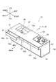
図1に表したように、システムキッチン10は、カウンター12と、キャビネット14と、を備える。カウンター12は、キャビネット14の上に設けられている。カウンター12は、平板状であり、上面12aの上に物品を載置可能である。キャビネット14は、箱状であり、内部の空間に物品を収納可能である。物品は、例えば、調理器具や調味料などのキッチン用品を含む。物品は、キッチン用品に限ることなく、カウンター12の上に載置可能、あるいはキャビネット14内に収納可能な任意のものでよい。
Hereinafter, embodiments will be described with reference to the drawings. In addition, in each drawing, the same code | symbol is attached | subjected to the same component and detailed description is abbreviate | omitted suitably.
(First embodiment)
FIG. 1 is a perspective view illustrating a system kitchen according to the first embodiment.
As shown in FIG. 1, the
カウンター12の上面12aには、例えば、水栓金具20と、シンク22と、加熱調理器24と、が設けられている。水栓金具20は、図示を省略した給水管に接続され、使用者の操作に応じて吐水及び止水を切り替える。シンク22は、上面12aよりも下方に凹む凹状である。シンク22は、水栓金具20と近接して配置され、水栓金具20から吐水された水を受ける。また、シンク22の内底面には、排水口が設けられている。排水口は、排水管に接続されている。これにより、シンク22は、水栓金具20から吐水された水などを排水管に流す。加熱調理器24は、例えば、ガスコンロ、電気コンロ、又はIHクッキングヒーター(電磁調理器)などである。
On the
カウンター12は、例えば、上面視において略長方形の平板状である。カウンター12の上面12aの形状は、略長方形である。カウンター12及び上面12aの形状は、上記に限ることなく、シンク22や加熱調理器24などを配置可能、かつ物品を載置可能な任意の形状でよい。カウンター12には、例えば、ステンレス、人工大理石、又は人造大理石などが用いられる。シンク22には、例えば、カウンター12と同様の材料が用いられる。シンク22は、例えば、一体成形、あるいは接着などにより、カウンター12と略一体に設けられる。加熱調理器24は、例えば、キャビネット14内に載置され、カウンター12に設けられた開口を介して上方に露呈される。
The
システムキッチン10は、キッチン(調理スペース)をリビングルームやダイニングルームなどの居室と対面させる、いわゆる対面式キッチンである。シンク22及び加熱調理器24は、例えば、キッチン側に寄せて配置される。
The
図2は、第1の実施形態に係るキャビネットを表す断面図である。
図2は、図1のA1−A2線断面に相当する。
図2に表したように、キャビネット14は、居室側に設けられた3つのキャビネット本体30a〜30cと、キッチン側に設けられた3つのキャビネット本体30d〜30fと、各キャビネット本体30a〜30fのそれぞれに設けられた引き出し40a〜40fと、を有する。
FIG. 2 is a cross-sectional view illustrating the cabinet according to the first embodiment.
FIG. 2 corresponds to a cross section taken along line A1-A2 of FIG.
As shown in FIG. 2, the
このように、システムキッチン10では、背中合わせにキャビネット本体30a〜30fを設け、キャビネット本体30a〜30fのそれぞれに引き出し40a〜40fを設けることにより、居室側及びキッチン側の双方において物品を収納可能としている。
Thus, in the
以下では、キャビネット本体30a〜30cの向く方向(居室側を向く方向)を前方とし、これと反対の方向を後方とする。前方は、換言すれば、キッチン側に立ってシステムキッチン10と対面する使用者の向く方向である。また、前方を向く使用者の右手側を右側方とし、これと反対の方向を左側方とする。
Below, let the direction (direction which faces the living room side) which the cabinet
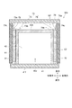
キャビネット本体30aは、右側側板31と、左側側板32と、背板33と、を有する。キャビネット本体30aは、上方、及び前方の少なくとも一部を開口させた略直方体の箱状である。キャビネット本体30aの上方の開口は、カウンター12によって塞がれる。
The
キャビネット本体30b、30cの構成は、キャビネット本体30aの構成と同様であるから、詳細な説明は省略する。なお、各キャビネット本体30a〜30cの形状は、必ずしも同一でなくてもよい。例えば、各キャビネット本体30a〜30cの左右方向の幅は、それぞれ異なってもよい。
Since the structure of the cabinet
キャビネット本体30dは、右側側板34と、左側側板35と、背板36と、を有する。キャビネット本体30dは、上方、及び後方の少なくとも一部を開口させた略直方体の箱状である。キャビネット本体30dの上方の開口は、カウンター12によって塞がれる。
The
キャビネット本体30e、30fの構成は、キャビネット本体30dの構成と同様であるから、詳細な説明は省略する。また、キャビネット本体30d内には、例えば、シンク22の一部が入り込み、キャビネット本体30fには、例えば、加熱調理器24の一部が入り込む。従って、キッチン側のキャビネット本体30d〜30fの構成は、シンク22や加熱調理器24の構成などに応じて適宜変更してもよい。例えば、キッチン側のキャビネット本体30d〜30fのいずれかは、引き出し式の収納に限ることなく、扉式の収納でもよい。
Since the structure of the cabinet
また、この例では、左右方向(カウンター12の長手方向)に並ぶ3つのキャビネット本体30a〜30c、及び30d〜30fを示しているが、左右方向に並ぶキャビネット本体の数は、3つに限ることなく、1つ又は2つでもよいし、4つ以上でもよい。キャビネット本体の数は、任意の数でよい。
In this example, three
引き出し40aは、前板41と、物品を収納可能な本体部42と、を有する。引き出し40aは、上方に開口する略直方体の開口箱状である。引き出し40aは、キャビネット本体30aの開口に前後方向に移動可能に挿通され、前後方向に移動によって開状態と閉状態とを切り替え可能である。引き出し40aは、閉状態においてキャビネット本体30aの開口を塞ぎ、開状態においてキャビネット本体30aの前方に突出し、本体部42への物品の出し入れを可能とする。閉状態は、例えば、図2に表した状態であり、開状態は、例えば、図1に表した状態である。
The
引き出し40dは、前板43と、物品を収納可能な本体部44と、を有する。引き出し40dは、上方に開口する略直方体の開口箱状である。引き出し40dは、キャビネット本体30dの開口に前後方向に移動可能に挿通され、前後方向に移動によって開状態と閉状態とを切り替え可能である。引き出し40dは、閉状態においてキャビネット本体30dの開口を塞ぎ、開状態においてキャビネット本体30dの後方に突出し、本体部44への物品の出し入れを可能とする。
The
引き出し40b、40cの構成は、引き出し40aの構成と同様であるから、詳細な説明は省略する。また、引き出し40e、40fの構成は、引き出し40dの構成と同様であるから、詳細な説明は省略する。
Since the configuration of the
キャビネット14は、右側サイドパネル51と、左側サイドパネル52と、をさらに有する。右側サイドパネル51は、キャビネット本体30aの右側側板31の右側外壁31Rに設けられる。また、右側サイドパネル51は、キャビネット本体30dの右側側板34の右側外壁34Rに設けられる。左側サイドパネル52は、キャビネット本体30cの左側側板32の左側外壁32Lに設けられる。また、左側サイドパネル52は、キャビネット本体30fの左側側板35の左側外壁35Lに設けられる。
The
このように、右側サイドパネル51は、左右方向に並ぶ各キャビネット本体30a〜30fのうちの最も右側に位置するキャビネット本体30a、30dの右側側板31、34の右側外壁31R、34Rを覆う。そして、左側サイドパネル52は、左右方向に並ぶ各キャビネット本体30a〜30fのうちの最も左側に位置するキャビネット本体30c、30fの左側側板32、35の左側外壁32L、35Lを覆う。これにより、システムキッチン10の見栄えを向上させることができる。
Thus, the
また、システムキッチン10では、キャビネット本体30a、30dの合わせ目を右側サイドパネル51で覆い、キャビネット本体30c、30fの合わせ目を左側サイドパネル52で覆う。これにより、居室側及びキッチン側の双方に収納(引き出し40a〜40f)を設ける場合においても、合わせ目を露出させることなく、システムキッチン10の見栄えを向上させることができる。
In the
図1及び図2に表したように、引き出し40a〜40cを閉状態にした場合、それぞれの前板41の前面41fの前後方向の位置は、略同一である。換言すれば、引き出し40a〜40cの前面41fは、略面一である。また、右側サイドパネル51の前端51fの位置、及び左側サイドパネル52の前端52fの位置は、閉状態にある引き出し40a〜40cの前面41fの位置と略同一である。これにより、キャビネット14の前面にフラットな面を形成し、システムキッチン10の見栄えを向上させることができる。なお、「略同一」とは、例えば、部材間の位置の差が1mm以下の状態をいう。
As shown in FIGS. 1 and 2, when the
また、隣り合う2つの引き出し40a、40bのそれぞれの前板41同士の左右方向の間隔PT1は、例えば、5mm以下である。引き出し40b、40cのそれぞれの前板41同士の左右方向の間隔PT2は、例えば、5mm以下である。これにより、前板41同士の間に過度な隙間が空いて見栄えの低下を招いてしまうことを抑制することができる。さらに、引き出し40a〜40cの開閉の際に、引き出し同士が接触してしまうことを抑制することができる。
Moreover, the space | interval PT1 of the left-right direction of each
引き出し40aの前板41と右側サイドパネル51との間の左右方向の間隔PT3、及び、引き出し40cの前板41と左側サイドパネル52との間の左右方向の間隔PT4は、例えば、1mm以上3mm以下である。
A left-right distance PT3 between the
同様に、引き出し40d〜40fを閉状態にした場合、それぞれの前板43の前面43fの前後方向の位置は、略同一である。右側サイドパネル51の後端51bの位置、及び左側サイドパネル52の後端52bの位置は、閉状態にある引き出し40d〜40fの前面43fの位置と略同一である。引き出し40d、40eのそれぞれの前板43同士の左右方向の間隔PT5は、例えば、5mm以下である。引き出し40e、40fのそれぞれの前板43同士の左右方向の間隔PT6は、例えば、5mm以下である。引き出し40dの前板43と右側サイドパネル51との間の左右方向の間隔PT7、及び、引き出し40fの前板43と左側サイドパネル52との間の左右方向の間隔PT8は、例えば、1mm以上3mm以下である。
Similarly, when the
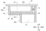
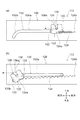
図3は、第1の実施形態に係るキャビネットの一部を表す部分断面図である。
図3は、図2のB1−B2線断面に相当する。
図3に表したように、引き出し40aの前板41の下端は、本体部42の下端よりも下方に延びる。これにより、引き出し40aにおいては、前板41の下端に指を掛けることで、開閉し易くすることができる。例えば、前板41の前面41fに取っ手などを設ける必要が無く、システムキッチン10の見栄えを向上させることができる。
FIG. 3 is a partial cross-sectional view showing a part of the cabinet according to the first embodiment.
FIG. 3 corresponds to a cross section taken along line B1-B2 of FIG.
As shown in FIG. 3, the lower end of the
カウンター12の前端12fは、閉状態にある引き出し40aの前板41の前面41fよりも前方に延びる。カウンター12の前端12fは、閉状態にある引き出し40a〜40cのそれぞれの前板41の前面41fよりも前方に延びる。また、カウンター12の前端12fは、右側サイドパネル51の前端及び左側サイドパネル52の前端よりも前方に延びる。これにより、上方から見た際に、閉状態の引き出し40a〜40c、右側サイドパネル51、及び左側サイドパネル52を、カウンター12で覆い、システムキッチン10の見栄えをより向上させることができる。
The
同様に、カウンター12の後端12b(図1参照)は、閉状態にある引き出し40d〜40fのそれぞれの前板43の前面43f(図2参照)よりも後方に延びるとともに、右側サイドパネル51の後端及び左側サイドパネル52の後端よりも後方に延びる。これにより、システムキッチン10の見栄えをより向上させることができる。
Similarly, the
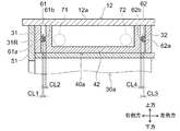
図4は、第1の実施形態に係るキャビネットの一部を表す部分断面図である。
図4は、図3のC1−C2線断面に相当する。
図4に表したように、キャビネット本体30aは、一対のレール61、62を有する。レール61は、アウターレール61aと、インナーレール61bと、を有する。アウターレール61aは、キャビネット本体30aの右側側板31の内壁に取り付けられている。アウターレール61aは、前後方向に延びる断面略U字状の部材である。インナーレール61bは、前後方向に延びる棒状又は板状の部材である。インナーレール61bは、アウターレール61a内に嵌り、ボールベアリングなどを介して前後方向にスライド移動可能にアウターレール61aに保持される。
FIG. 4 is a partial cross-sectional view showing a part of the cabinet according to the first embodiment.
4 corresponds to a cross section taken along line C1-C2 of FIG.
As illustrated in FIG. 4, the
レール62は、レール61と同様に、アウターレール62aと、インナーレール62bと、を有する。アウターレール62aは、キャビネット本体30aの左側側板32の内壁に、レール61と対向して取り付けられる。インナーレール62bは、前後方向にスライド移動可能にアウターレール62aに保持される。
The
また、インナーレール61bは、引き出し40aの本体部42の右側外側面に取り付けられる。インナーレール62bは、引き出し40aの本体部42の左側外側面に取り付けられる。これにより、引き出し40aが、レール61、62を介してキャビネット本体30aに前後方向に移動可能に保持される。例えば、レール61、62が無い場合に比べて、引き出し40aを前後方向にスムーズに移動させることができる。
The
アウターレール61aとインナーレール61bとの間には、隙間CL1が設けられている。また、アウターレール61aと引き出し40aの本体部42との間には、隙間CL2が設けられている。同様に、アウターレール62aとインナーレール62bとの間には、隙間CL3が設けられている。アウターレール62aと引き出し40aの本体部42との間には、隙間CL4が設けられている。
A gap CL1 is provided between the
これにより、引き出し40aは、前後方向に移動可能にキャビネット本体30aに保持されるとともに、各隙間CL1〜CL4の分だけ僅かに左右方向に移動可能にキャビネット本体30aに保持される。各隙間CL1〜CL4は、換言すれば、各部材間の遊びである。各隙間CL1〜CL4の左右方向の長さは、例えば、5mm以下である。すなわち、引き出し40aは、キャビネット本体30aに保持された状態において、5mm以下の範囲で左右方向に移動する。
Accordingly, the
キャビネット本体30b、30cは、同様に、レール61、62を有し、引き出し40b、40cを前後方向及び左右方向に移動可能に保持する。キャビネット本体30d〜30fは、レール63、64(図2参照)を有し、引き出し40d〜40fを前後方向及び左右方向に移動可能に保持する。レール63、64は、レール61、62と同様であるから、詳細な説明は省略する。
Similarly, the
図5は、第1の実施形態に係るキャビネットの一部を表す部分断面図である。
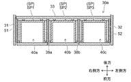
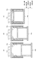
図2〜図5に表したように、キャビネット14は、姿勢調整機構70をさらに有する。姿勢調整機構70は、居室側に並ぶ各キャビネット本体30a〜30cのそれぞれに設けられる。すなわち、この例において、キャビネット14は、キャビネット本体30a〜30cのそれぞれに対応する3つの姿勢調整機構70を有する。
FIG. 5 is a partial cross-sectional view showing a part of the cabinet according to the first embodiment.
As illustrated in FIGS. 2 to 5, the
姿勢調整機構70は、2つの調整部71、72を有する。調整部71、72は、キャビネット本体30aの収納空間SP内に設けられている。調整部71は、引き出し40aの本体部42の背面42bの右側の部分に当接する。調整部72は、引き出し40aの本体部42の背面42bの左側の部分に当接する。調整部の数は、2つに限ることなく、3つ以上でもよい。複数の調整部は、引き出し40aの背面42bに対して少なくとも左右の2箇所に当接するように、キャビネット本体30aの収納空間SP内に設けられていればよい。
The
調整部71は、雄螺子状の螺子本体71aと、螺子本体71aの一端に設けられた摘み部71bと、摘み部71bの螺子本体71aと反対側の端面に設けられた緩衝部材71cと、を有する。
The
螺子本体71aは、キャビネット本体30aの背板33に設けられた雌螺子部(図示は省略)に螺合することにより、背板33に取り付けられる。
The
摘み部71bは、螺子本体71aの軸方向に対して垂直な方向に延びる。これにより、摘み部71bは、ドライバーなどの工具を用いることなく、螺子本体71aを指で回すことを可能とする。摘み部71bは、例えば、螺子本体71aよりも大きい径を有し、外周面にローレットが設けられた円板状である。摘み部71bの形状は、上記に限ることなく、螺子本体71aを指で回すことが可能な任意の形状でよい。
The
緩衝部材71cは、引き出し40aの背面42bに当接する部分である。緩衝部材71cには、例えば、樹脂材料などの弾性を有する材料が用いられる。緩衝部材71cには、例えば、ゴムなどの軟質な材料を用いることが好ましい。これにより、緩衝部材71cは、調整部71が引き出し40aに当接する際の衝撃を和らげる。
The
調整部72は、調整部71と同様に、雄螺子状の螺子本体72aと、螺子本体72aの一端に設けられた摘み部72bと、摘み部72bの螺子本体72aと反対側の端面に設けられた緩衝部材72cと、を有する。
Similar to the
このように、調整部71、72は、螺子である。より詳しくは、指で回すことが可能な摘み螺子である。調整部71、72は、回転に応じて、背板33からの突出量を変化させる。
Thus, the
姿勢調整機構70では、調整部71、72の背板33からの突出量を調整することにより、レール61、62の各隙間CL1〜CL4の範囲内において、閉状態にある引き出し40aの姿勢を調整することができる。姿勢調整機構70は、引き出し40aの全体の左右方向の傾きを調整する。換言すれば、姿勢調整機構70は、引き出し40aの上下方向を軸とする回転の角度を調整する。
In the
例えば、調整部71の突出量を、調整部72の突出量よりも多くする。これにより、引き出し40aの前面41fを左側に向けて傾けることができる。反対に、調整部72の突出量を、調整部71の突出量よりも多くする。これにより、引き出し40aの前面41fを右側に向けて傾けることができる。
For example, the protrusion amount of the
さらに、姿勢調整機構70は、調整部71、72の突出量により、引き出し40aの前後方向の位置を調整する。このように、姿勢調整機構70は、引き出し40aの左右方向の傾きを調整可能とするとともに、引き出し40aの前後方向の位置を調整可能とする。
Further, the
キャビネット14では、居室側の各キャビネット本体30a〜30cのそれぞれに姿勢調整機構70が設けられる。従って、キャビネット14では、居室側の各引き出し40a〜40cの姿勢を任意の調整することができる。
In the
各姿勢調整機構70は、例えば、前面41fが前後方向と直交する状態(図5に表した状態)を0°とした時に、左右方向(上下方向を軸とする軸周り)に±0.5°の範囲で引き出し40a〜40cの姿勢を調整可能とする。これにより、例えば、各引き出し40a〜40cのそれぞれの傾きの誤差を0.5°以内にすることができる。なお、本発明において、調整可能範囲は、±0.5°の範囲に限らない。例えば、調整可能範囲が、±1°の範囲のものも、本発明に含まれる。
Each
図6は、第1の実施形態に係るキャビネットの引き出しの調整の一例を表す説明図である。
図6に表したように、右側サイドパネル51及び左側サイドパネル52を有するキャビネット14では、製造誤差や取付誤差などにより、右側サイドパネル51の前端51fの位置と左側サイドパネル52の前端52fの位置とが、前後方向において異なってしまう場合がある。なお、図6では、便宜的に、居室側のキャビネット本体30a〜30cのみを図示している。
FIG. 6 is an explanatory diagram illustrating an example of adjustment of the drawer of the cabinet according to the first embodiment.
As shown in FIG. 6, in the
この際、本実施形態に係るシステムキッチン10のキャビネット14では、図6に表したように、各姿勢調整機構70により、各引き出し40a〜40cの前板41の前面41fが、閉状態において、右側サイドパネル51の前端51fと左側サイドパネル52の前端52fとを含む仮想的な平面VPと一致するように、各引き出し40a〜40cの姿勢を調整することができる。
At this time, in the
ここで、仮想的な平面VPは、より詳しくは、上面視において、右側サイドパネル51の前端51fの左側端部51fcと、左側サイドパネル52の前端52fの右側端部52fcと、を結ぶ面である。
More specifically, the virtual plane VP is a plane connecting the left end 51fc of the
このように、キャビネット14では、各引き出し40a〜40cの前板41の前面41fが、閉状態において、仮想的な平面VPと一致するように、姿勢調整機構70が、各引き出し40a〜40cの姿勢を調整するので、右側サイドパネル51と引き出し40aとの間、及び左側サイドパネル52と引き出し40cとの間に生じる前後方向の段差を抑制することができる。また、引き出し40a〜40c自体の姿勢を調整することにより、前板41の位置及び傾きを調整する構成に比べ、簡単な構成で調整を行うことができ、かつ開状態とした際にも、調整機構が露出してしまうことを抑制することができる。従って、簡単な構成で、キャビネット14の見栄えをより向上させることができる。
As described above, in the
また、キャビネット14では、姿勢調整機構70が、引き出し40a〜40cの背面42bに対して少なくとも左右の2箇所に当接するように、キャビネット本体30a〜30cの収納空間SP内に設けられた複数の調整部71、72を有する。これにより、引き出し40a〜40cの姿勢を簡単な構成で調整することができる。また、姿勢の調整により、引き出し40a〜40c自体の容量が変化してしまうことを防ぐこともできる。
Further, in the
また、キャビネット14では、調整部71、72が、キャビネット本体30a〜30cの背板33の収納空間SP側に設けられた螺子であり、背板33からの突出量を調整することにより、前面41fが平面VPと一致するように、引き出し40a〜40cの角度を調整可能としている。これにより、螺子を回転させるだけで、姿勢の調整を簡単に行うことができる。また、螺子の回転具合により、背板33からの突出量を精密に調整することができ、引き出し40a〜40cの角度も精密に調整することができる。また、調整部71、72では、工具などを用いることなく、指で回すことができる。これにより、調整をより容易にすることができる。
Moreover, in the
例えば、製造誤差により、右側サイドパネル51及び左側サイドパネル52のそれぞれの前後方向の長さが異なる場合には、右側サイドパネル51の後端51bの位置、及び左側サイドパネル52の後端52bの位置を、キッチン側の各引き出し40d〜40fの閉状態にした前板43の前面43fの位置に合わせる。そして、上記のように、居室側の各引き出し40a〜40cの前板41の前面41fが、閉状態において、仮想的な平面VPと一致するように、各引き出し40a〜40cの姿勢を調整する。これにより、キッチン側及び居室側の双方において、各引き出し40a〜40fと各サイドパネル51、52との間に段差が生じることを抑制することができる。
For example, when the lengths in the front-rear direction of the
このように、キッチン側のキャビネット本体30d〜30fには、必ずしも姿勢調整機構70を設ける必要がない。居室側のキャビネット本体30a〜30cのみに姿勢調整機構70を設けた場合にも、キッチン側及び居室側の双方において、各サイドパネル51、52との段差の発生を適切に抑制することができる。
Thus, it is not always necessary to provide the
なお、上記とは反対に、キッチン側のキャビネット本体30d〜30fのみに姿勢調整機構70を設けてもよい。このように、対面式のシステムキッチン10において、居室側のキャビネット本体30a〜30c、及びキッチン側のキャビネット本体30d〜30fの一方のみに姿勢調整機構70を設ける。これにより、システムキッチン10において、部品点数の増加を抑制することができる。例えば、各サイドパネル51、52との段差の発生を抑制して、キャビネット14の見栄えを向上させる場合にも、キャビネット14の製造コストの増加を抑制することができる。
Contrary to the above, the
なお、図6に表したように、引き出し40a〜40cの姿勢を調整した状態で、引き出し40a〜40cを閉状態から開状態にした場合、引き出し40a〜40cは、閉状態と同じ姿勢のまま開状態となってもよい。あるいは、閉状態から開状態に遷移する場合には、引き出し40a〜40cが傾いていない状態で引き出されるようにしてもよい。
As shown in FIG. 6, when the
図7は、第1の実施形態に係るキャビネットの変形例を表す部分断面図である。
図7に表したように、この例では、姿勢調整機構70が、調整部73、74を有する。調整部73は、略L字状に屈曲した板状であり、キャビネット本体30aの右側側板31の内壁に当接する第1板部73aと、引き出し40aの背面42bに当接する第2板部73bと、を有する。第1板部73aには、前後方向に延びる長穴73cが設けられている。そして、調整部73は、長穴73cに挿通された螺子75により、右側側板31に取り付けられる。この際、調整部73は、長穴73cに沿って前後方向に移動可能に右側側板31に取り付けられる。
FIG. 7 is a partial cross-sectional view illustrating a modification of the cabinet according to the first embodiment.
As shown in FIG. 7, in this example, the
調整部74は、調整部73と同様に、第1板部74aと第2板部74bとを有し、第1板部74aに設けられた長穴74c及び螺子76を介して前後方向に移動可能に左側側板32に取り付けられる。
Similar to the
この調整部73、74においても、引き出し40aの左右方向の傾き、及び引き出し40aの前後方向の位置を調整することができる。すなわち、各引き出し40aの前板41の前面41fが、閉状態において、仮想的な平面VPと一致するように、引き出し40aの姿勢を調整することができる。
The
このように、調整部73、74は、右側側板31、左側側板32に設けてもよい。姿勢調整機構70の構成は、上記のように引き出し40a〜40cの姿勢を調整可能な任意の構成でよい。
As described above, the
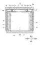
図8は、第1の実施形態に係るキャビネットの変形例を表す部分断面図である。
図8に表したように、この例では、キャビネット本体30aが、仕切り板38a、38bを有する。仕切り板38a、38bは、右側側板31と左側側板32との間に設けられ、キャビネット本体30aの収納空間SPを複数の空間に仕切る。この例において、仕切り板38a、38bは、収納空間SPを左右方向に並ぶ3つの空間SP1〜SP3に仕切る。そして、この例では、引き出し40aが、右側側板31と仕切り板38aとの間の空間SP1に挿通され、引き出し40bが、仕切り板38a、38bの間の空間SP2に挿通され、引き出し40cが、左側側板32と仕切り板38bとの間の空間SP3に挿通されている。
FIG. 8 is a partial cross-sectional view illustrating a modification of the cabinet according to the first embodiment.
As shown in FIG. 8, in this example, the
上記実施形態では、複数のキャビネット本体30a〜30cを並べて設け、各キャビネット本体30a〜30cのそれぞれに1つの引き出し40a〜40cを挿通している。これに限ることなく、図8に表したように、1つのキャビネット本体30aの収納空間を複数の空間に仕切ることにより、1つのキャビネット本体30aに複数の引き出し40a〜40cを挿通するようにしてもよい。
In the above embodiment, a plurality of
この例では、引き出し40aが、閉状態において、キャビネット本体30aの開口の一部を塞ぐ。このように、引き出し40aは、キャビネット本体30aの開口の全体を塞ぐものに限ることなく、キャビネット本体30aの開口の一部を塞ぐものでもよい。すなわち、引き出し40aは、キャビネット本体30aの開口の少なくとも一部を塞ぐものであればよい。なお、仕切り板38a、38bの数、仕切られた空間SP1〜SP3の数、及び1つのキャビネット本体30aに挿通する引き出し40a〜40cの数などは、上記に限ることなく、任意の数でよい。
In this example, the
(第2の実施形態)
図9は、第2の実施形態に係るキャビネットの一部を表す部分断面図である。
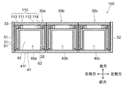
図9に表したように、キャビネット100では、上記第1の実施形態に関して説明したキャビネット14の姿勢調整機構70が、角度調整機構110に置き換えられている。なお、上記第1の実施形態と機能・構成上実質的に同じものについては、同符号を付し、詳細な説明を省略する。図9は、上記第1の実施形態に関して説明したシステムキッチン10のA1−A2線断面に相当する。また、図9では、便宜的に、居室側のキャビネット本体30a〜30cのみを図示し、キッチン側のキャビネット本体30d〜30fの図示を省略している。
(Second Embodiment)
FIG. 9 is a partial cross-sectional view showing a part of the cabinet according to the second embodiment.
As shown in FIG. 9, in the
角度調整機構110は、2つの調整部111、112と、2つの引き込み機構113、114と、を有する。調整部111、112は、上記第1の実施形態に関して説明した調整部71、72と実質的に同じであるから、詳細な説明は省略する。
The
角度調整機構110は、調整部111、112の突出量により、引き出し40aの上下方向を軸とする回転の角度を調整する。換言すれば、角度調整機構110は、引き出し40aの左右方向の傾きを調整する。また、角度調整機構110は、調整部111、112の突出量により、引き出し40aの前後方向の位置を調整する。このように、角度調整機構110は、引き出し40aの左右方向の角度を調整可能とするとともに、引き出し40aの前後方向の位置を調整可能とする。
The
図10(a)〜図10(c)は、第2の実施形態に係るキャビネットの一部を表す部分断面図である。
図10(a)〜図10(c)に表したように、引き出し40aは、閉じ位置と全開位置との間で前後方向に移動する。閉じ位置は、引き出し40aが閉状態となる位置である。全開位置は、例えば、レール61、62に設けられたストッパなどにより、前方への移動が規制された位置である。全開位置は、例えば、ストッパなどを有しない場合には、引き出し40aがキャビネット本体30aから抜ける直前の位置としてもよい。
Fig.10 (a)-FIG.10 (c) are the fragmentary sectional views showing a part of cabinet which concerns on 2nd Embodiment.
As shown in FIGS. 10A to 10C, the
引き出し40aは、開状態において、全開位置と中間位置との間の第1開状態と、中間位置と閉じ位置との間の第2開状態と、を有する。中間位置は、全開位置と閉じ位置との間の任意の位置でよい。
In the open state, the
引き込み機構113、114は、引き出し40aが第2開状態にある際に、引き出し40aに弾性力を付与することにより、引き出し40aを第2開状態から閉状態に切り替えさせる。換言すれば、引き込み機構113、114は、引き出し40aが中間位置と閉じ位置との間に位置する際に、閉じ位置に向かう方向の弾性力を引き出し40aに付与することにより、引き出し40aを閉じ位置に移動させる。
The pull-in
一方、引き込み機構113、114は、引き出し40aが第1開状態にある際には、引き出し40aに閉じ位置に向かう方向の弾性力を付与しない。このように、引き込み機構113、114は、引き出し40aが中間位置と閉じ位置との間に位置する場合には、引き出し40aに閉じ位置に向かう方向の弾性力を付与し、引き出し40aが中間位置よりも前方に移動した場合には、閉じ位置に向かう方向の弾性力の付与を解除する。
On the other hand, when the
これにより、例えば、引き出し40aが中途半端に開いた状態で保持されてしまうことを抑制することができる。また、引き出し40aを第1開状態で保持することができ、引き出し40aに物品を出し入れし易くすることができる。
Thereby, it can suppress that the
なお、引き出し40aが中間位置よりも前方に移動した場合には、反対に、全開位置に向かう方向の弾性力を引き出し40aに付与してもよい。この場合、引き出し40aを押し出す押し出し機構を別途設けてもよいし、引き込み機構113、114に押し出し機構の機能を持たせてもよい。
When the
図11(a)及び図11(b)は、第2の実施形態に係る引き込み機構の具体例を表す説明図である。
図11(a)及び図11(b)に表したように、引き込み機構113は、レール部材120と、可動部材122と、バネ124と、駆動ピン126と、を有する。なお、引き込み機構114の構成は、引き込み機構114の構成と実質的に同じであるから、詳細な説明は省略する。
Fig.11 (a) and FIG.11 (b) are explanatory drawings showing the specific example of the drawing-in mechanism which concerns on 2nd Embodiment.
As illustrated in FIGS. 11A and 11B, the pull-in
レール部材120は、貫通孔状のレール130を有する板状である。レール部材120は、例えば、キャビネット本体30aの右側側板31の内壁に取り付けられる。レール130は、前後方向に延びる直線部130aと、直線部130aの前端に設けられ、下方に向かって円弧状に湾曲した湾曲部130bと、を有する。
The
可動部材122は、略矩形の板状であり、軸部132、133を介してレール130に取り付けられ、レール130に沿って前後方向に移動する。可動部材122の上部には、上方に向かって開口する溝部136が設けられている。溝部136の前方側の上端付近には、上方に向かうに従って幅が広がるように前方側に傾斜した傾斜部136aが設けられている。
The
バネ124は、いわゆるコイルバネである。バネ124の一端124aは、可動部材122に接続されている。一方、バネ124の他端124bは、レール部材120に接続されている。バネ124の他端124bは、例えば、キャビネット本体30aに接続してもよい。
The
バネ124は、後方側に向かう弾性力を可動部材122に付与する。バネ124は、可動部材122がレール130の直線部130aの範囲に位置する場合に、可動部材122を直線部130aの後端の位置(図11(a)に表した位置)に保持する。より詳しくは、バネ124は、弾性力により、軸部133が直線部130aの後端に当接した位置に、可動部材122を保持する。
The
駆動ピン126は、例えば、左右方向(図11において紙面と直交する方向)に延びる略丸棒状である。駆動ピン126の一端は、可動部材122の溝部136に係合している。一方、駆動ピン126の他端は、引き出し40aの本体部42に接続されている。これにより、駆動ピン126及び可動部材122は、引き出し40aに従動して前後方向に移動する。
The
可動部材122が、レール130の直線部130aの範囲に位置する場合には、可動部材122及び駆動ピン126を介してバネ124の弾性力が、引き出し40aに付与される。これにより、上述のように、引き出し40aが第2開状態にある際には、引き出し40aが閉じ位置に移動する。図11(a)は、換言すれば、引き出し40aが閉じ位置にある状態を示している。
When the
図11(b)に表したように、可動部材122が、レール130の湾曲部130bの位置まで移動すると、湾曲部130bの湾曲に沿って可動部材122が前方側に傾く。この状態において、引き出し40a及び駆動ピン126がさらに前方に移動すると、駆動ピン126が可動部材122の溝部136から抜ける。これにより、上述のように、引き出し40aが第1開状態にある際には、引き出し40aへの弾性力の付与が解除される。図11(b)は、換言すれば、引き出し40bが中間位置にある状態を示している。
As shown in FIG. 11B, when the
また、湾曲部130bの位置にある可動部材122は、軸部132を湾曲部130bの前端部分に係合させることにより、バネ124の弾性力に抗して湾曲部130bの位置に留まる。そして、引き出し40a及び駆動ピン126が第1開状態の位置から中間位置まで戻った際に、再び駆動ピン126と溝部136とを係合させる。
Further, the
これにより、上記のように、引き込み機構113、114により、引き出し40aが中間位置と閉じ位置との間に位置する場合には、引き出し40aに閉じ位置に向かう方向の弾性力を付与し、引き出し40aが中間位置よりも前方に移動した場合には、閉じ位置に向かう方向の弾性力の付与を解除することができる。
Thus, as described above, when the
なお、引き込み機構113、114の構成は、上記に限ることなく、上記のように引き出し40aへの弾性力の付与、及び弾性力の付与の解除を行うことができる任意の構成でよい。
Note that the configuration of the pull-in
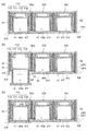
図12(a)〜図12(c)は、第2の実施形態に係るキャビネットの引き出しの調整の一例を表す説明図である。
図12(a)に表したように、角度調整機構110は、右側サイドパネル51の前端51fの位置と左側サイドパネル52の前端52fの位置とが、前後方向において異なる際に、各引き出し40a〜40cの前板41の前面41fが、閉状態において、右側サイドパネル51の前端51fと左側サイドパネル52の前端52fとを含む仮想的な第1平面VP1と一致するように、各引き出し40a〜40cの角度を調整可能とする。
FIGS. 12A to 12C are explanatory diagrams illustrating an example of adjustment of the drawer of the cabinet according to the second embodiment.
As illustrated in FIG. 12A, the
角度調整機構110は、調整部111、112の突出量と、レール61、62の各隙間CL1〜CL4と、引き込み機構113、114の弾性力とによって、引き出し40a〜40cの角度を調整可能とする。
The
また、角度調整機構110は、図12(b)に表したように、右側側板31の前端31fと左側側板32の前端32fとを含む仮想的な第2平面VP2に対する各引き出し40a〜40cの前面41fの角度を、開状態と閉状態とで異ならせることを可能とする。
In addition, as shown in FIG. 12B, the
図12(b)に表したように、角度調整機構110は、例えば、開状態において、引き出し40a〜40cの前板41の前面41fが、第2平面VP2と平行になることを許容する。この例では、引き出し40a〜40cを開状態にした場合に、レール61、62の各隙間CL1〜CL4により、前面41fが第2平面VP2と平行になることが許容される。
As illustrated in FIG. 12B, the
調整部111の突出量を、調整部112の突出量よりも大きくした状態で、引き出し40aを開状態から閉状態に移行させると、図12(c)に表したように、移行の途中において、調整部111のみが引き出し40aの背面42bに当接し、調整部112は、引き出し40aの背面42bに当接していない状態が生じる。この状態から、引き出し40aをさらに後方に押し込むと、調整部111を軸に引き出し40aが回転し、引き出し40aの角度が切り替わる。そして、引き出し40aの背面42bが、調整部112に当接することにより、図12(a)に表したように、引き出し40aが閉状態となる。
When the
このように、角度調整機構110は、引き出し40a〜40cが開状態から閉状態に移行する途中で、第1平面VP1と平行になるように、引き出し40a〜40cの角度を切り替える。また、角度調整機構110は、引き込み機構113、114を有する。この場合、上記の角度の切り替えを、引き込み機構113、114の弾性力によって自動的に行うことができる。引き込み機構113、114は、引き出し40a〜40cが第2開状態にある際に、弾性力により、第1平面VP1と平行になるように、引き出し40a〜40cの角度を切り替える。
Thus, the
このように、本実施形態に係るキャビネット100では、引き出し40a〜40cの前板41の前面41fが、閉状態において、右側サイドパネル51の前端51fと左側サイドパネル52の前端52fとを含む仮想的な第1平面VP1と一致するように、角度調整機構110が、引き出し40a〜40cの角度を調整するので、右側サイドパネル51と引き出し40aとの間、及び左側サイドパネル52と引き出し40cとの間に生じる前後方向の段差を抑制することができる。また、引き出し40a〜40c自体の角度を調整することにより、前板41の位置及び傾きを調整する構成に比べ、簡単な構成で調整を行うことができ、かつ開状態とした際にも、調整機構が露出してしまうことを抑制することができる。従って、簡単な構成で、キャビネット100の見栄えをより向上させることができる。
Thus, in the
また、開状態では、右側側板31の前端31fと左側側板32の前端32fとを含む仮想的な第2平面VP2と平行になることが許容されるため、引き出し40a〜40cを引き出し易くすることができる。また、開状態において、引き出し40a〜40cが傾いて見えてしまうことを抑制し、開状態とした際のキャビネット100の見栄えの低下も抑制することができる。
In the open state, since it is allowed to be parallel to the virtual second plane VP2 including the
また、キャビネット100では、角度調整機構110が引き込み機構113、114を有し、引き込み機構113、114の弾性力により、引き出し40a〜40cの角度を自動的に調整することができる。
Further, in the
また、キャビネット100では、角度調整機構110が、引き出し40a〜40cの背面42bに対して少なくとも左右の2箇所に当接するように、キャビネット本体30a〜30cの収納空間SP内に設けられた複数の調整部111、112を有する。これにより、引き出し40a〜40cの姿勢を簡単な構成で調整することができる。また、姿勢の調整により、引き出し40a〜40c自体の容量が変化してしまうことを防ぐこともできる。
Further, in the
また、キャビネット100では、調整部111、112が、キャビネット本体30a〜30cの背板33の収納空間SP側に設けられた螺子であり、背板33からの突出量を調整することにより、前面41fが第1平面VP1と一致するように、引き出し40a〜40cの角度を調整可能としている。これにより、螺子を回転させるだけで、角度の調整を簡単に行うことができる。また、螺子の回転具合により、背板33からの突出量を精密に調整することができ、引き出し40a〜40cの角度も精密に調整することができる。また、調整部111、112では、工具などを用いることなく、指で回すことができる。これにより、調整をより容易にすることができる。
Further, in the
なお、上記各実施形態では、キャビネット14、100をシステムキッチン10に適用した例を示している。キャビネット14、100は、システムキッチン10に限ることなく、例えば、トイレ空間の手洗い器の下方に設置されるキャビネットや、洗面空間の洗面ボウルの下方に設置されるキャビネットなどに適用してもよい。
In addition, in each said embodiment, the example which applied the
以上、本発明の実施の形態について説明した。しかし、本発明はこれらの記述に限定されるものではない。前述の実施の形態に関して、当業者が適宜設計変更を加えたものも、本発明の特徴を備えている限り、本発明の範囲に包含される。例えば、システムキッチン10及びキャビネット14、100などが備える各要素の形状、寸法、材質、配置などは、例示したものに限定されるわけではなく適宜変更することができる。
また、前述した各実施の形態が備える各要素は、技術的に可能な限りにおいて組み合わせることができ、これらを組み合わせたものも本発明の特徴を含む限り本発明の範囲に包含される。
The embodiment of the present invention has been described above. However, the present invention is not limited to these descriptions. As long as the features of the present invention are provided, those skilled in the art appropriately modified the design of the above-described embodiments are also included in the scope of the present invention. For example, the shape, size, material, arrangement, and the like of each element included in the
Moreover, each element with which each embodiment mentioned above is provided can be combined as long as technically possible, and the combination of these is also included in the scope of the present invention as long as it includes the features of the present invention.
10 システムキッチン、 12 カウンター、 14、100 キャビネット、 20 水栓金具、 22 シンク、 24 加熱調理器、 30a〜30f キャビネット本体、 31、34 右側側板、 32、35 左側側板、 33、36 背板、 38a、38b 仕切り板、 40a〜40f 引き出し、 41、43 前板、 42、44 本体部、 51 右側サイドパネル、 52 左側サイドパネル、 61〜64 レール、 70 姿勢調整機構、 71〜74 調整部、 75、76 螺子、 110 角度調整機構、 111、112 調整部、 113、114 引き込み機構、 120 レール部材、 122 可動部材、 124 バネ、 126 駆動ピン、 130 レール、 132、133 軸部、 136 溝部
10 system kitchen, 12 counter, 14, 100 cabinet, 20 faucet fitting, 22 sink, 24 heating cooker, 30a-30f cabinet body, 31, 34 right side plate, 32, 35 left side plate, 33, 36 back plate,
Claims (6)
前板と、物品を収納可能な本体部と、を有し、前記キャビネット本体の前記開口に前後方向に移動可能に挿通され、前記前後方向の移動によって開状態と閉状態とを切り替え可能であり、前記閉状態において前記キャビネット本体の前記開口を塞ぎ、前記開状態において前記キャビネット本体の前方に突出し、前記本体部への物品の出し入れを可能とする引き出しと、
前記右側側板の右側外壁に設けられた右側サイドパネルと、
前記左側側板の左側外壁に設けられた左側サイドパネルと、
前記右側サイドパネルの前端位置と前記左側サイドパネルの前端位置とが前記前後方向において異なる際に、前記引き出しの前記前板の前面が、前記閉状態において、前記右側サイドパネルの前端と前記左側サイドパネルの前端とを含む仮想的な平面と一致するように、前記引き出しの姿勢を調整可能とする姿勢調整機構と、
を備えたことを特徴とするキャビネット。 A cabinet body having a right side plate and a left side plate and having at least a part of the front opened;
It has a front plate and a main body that can store articles, is inserted in the opening of the cabinet main body so as to be movable in the front-rear direction, and can be switched between an open state and a closed state by the movement in the front-rear direction. A drawer that closes the opening of the cabinet body in the closed state, protrudes forward of the cabinet body in the open state, and allows an article to be taken in and out of the body portion;
A right side panel provided on the right outer wall of the right side plate;
A left side panel provided on a left outer wall of the left side plate;
When the front end position of the right side panel and the front end position of the left side panel are different in the front-rear direction, the front surface of the front plate of the drawer is in the closed state, and the front end of the right side panel and the left side A posture adjusting mechanism that allows the posture of the drawer to be adjusted so as to coincide with a virtual plane including the front end of the panel;
A cabinet characterized by comprising.
前板と、物品を収納可能な本体部と、を有し、前記キャビネット本体の前記開口に前後方向に移動可能に挿通され、前記前後方向の移動によって開状態と閉状態とを切り替え可能であり、前記閉状態において前記キャビネット本体の前記開口を塞ぎ、前記開状態において前記キャビネット本体の前方に突出し、前記本体部への物品の出し入れを可能とする引き出しと、
前記右側側板の右側外壁に設けられた右側サイドパネルと、
前記左側側板の左側外壁に設けられた左側サイドパネルと、
前記右側サイドパネルの前端位置と前記左側サイドパネルの前端位置とが前記前後方向において異なる際に、前記閉状態において前記引き出しの前記前板の前面が前記右側サイドパネルの前端と前記左側サイドパネルの前端とを含む仮想的な第1平面と一致するように、前記右側側板の前端と前記左側側板の前端とを含む仮想的な第2平面に対する前記前面の角度を前記開状態と前記閉状態とで異ならせることを可能とする角度調整機構と、
を備えたことを特徴とするキャビネット。 A cabinet body having a right side plate and a left side plate and having at least a part of the front opened;
It has a front plate and a main body that can store articles, is inserted in the opening of the cabinet main body so as to be movable in the front-rear direction, and can be switched between an open state and a closed state by the front-rear direction movement A drawer that closes the opening of the cabinet body in the closed state, protrudes forward of the cabinet body in the open state, and allows an article to be taken in and out of the body portion;
A right side panel provided on the right outer wall of the right side plate;
A left side panel provided on a left outer wall of the left side plate;
When the front end position of the right side panel and the front end position of the left side panel are different in the front-rear direction, the front surface of the front plate of the drawer is closed between the front end of the right side panel and the left side panel in the closed state. An angle of the front surface with respect to a virtual second plane including a front end of the right side plate and a front end of the left side plate so as to coincide with a virtual first plane including a front end is set to the open state and the closed state. An angle adjustment mechanism that makes it possible to vary
A cabinet characterized by comprising.
前記角度調整機構は、前記引き出しが前記第2開状態にある際に、前記引き出しに弾性力を付与することにより、前記引き出しを前記第2開状態から前記閉状態に切り替えさせるとともに、前記引き出しが前記第1開状態にある際には、前記引き出しに前記弾性力を付与しない引き込み機構を有し、
前記引き込み機構は、前記引き出しが前記第2開状態にある際に、前記弾性力により、前記第1平面と平行になるように前記引き出しの角度を切り替えることを特徴とする請求項3記載のキャビネット。 In the open state, the drawer has a first open state between a fully open position and an intermediate position, and a second open state between the intermediate position and a closed position,
The angle adjustment mechanism is configured to switch the drawer from the second open state to the closed state by applying an elastic force to the drawer when the drawer is in the second open state. A pull-in mechanism that does not apply the elastic force to the drawer when in the first open state;
4. The cabinet according to claim 3, wherein when the drawer is in the second open state, the pulling mechanism switches the angle of the drawer so as to be parallel to the first plane by the elastic force. .
Priority Applications (1)
| Application Number | Priority Date | Filing Date | Title |
|---|---|---|---|
| JP2016085267A JP6687891B2 (en) | 2016-04-21 | 2016-04-21 | cabinet |
Applications Claiming Priority (1)
| Application Number | Priority Date | Filing Date | Title |
|---|---|---|---|
| JP2016085267A JP6687891B2 (en) | 2016-04-21 | 2016-04-21 | cabinet |
Publications (2)
| Publication Number | Publication Date |
|---|---|
| JP2017192593A true JP2017192593A (en) | 2017-10-26 |
| JP6687891B2 JP6687891B2 (en) | 2020-04-28 |
Family
ID=60154415
Family Applications (1)
| Application Number | Title | Priority Date | Filing Date |
|---|---|---|---|
| JP2016085267A Active JP6687891B2 (en) | 2016-04-21 | 2016-04-21 | cabinet |
Country Status (1)
| Country | Link |
|---|---|
| JP (1) | JP6687891B2 (en) |
Cited By (3)
| Publication number | Priority date | Publication date | Assignee | Title |
|---|---|---|---|---|
| JP2021052872A (en) * | 2019-09-27 | 2021-04-08 | 株式会社Lixil | Drawer position adjustment member and cabinet with drawer |
| JP2021142130A (en) * | 2020-03-12 | 2021-09-24 | Toto株式会社 | cabinet |
| CN118304449A (en) * | 2024-04-02 | 2024-07-09 | 宁波方太厨具有限公司 | Sterilizing cabinet |
Citations (9)
| Publication number | Priority date | Publication date | Assignee | Title |
|---|---|---|---|---|
| JP2001104075A (en) * | 1999-10-13 | 2001-04-17 | Hitachi Chem Co Ltd | Drawer and furniture fitted therewith |
| JP2003174942A (en) * | 2001-12-12 | 2003-06-24 | Ota Seisakusho:Kk | Connector of drawer |
| EP1396212A1 (en) * | 2002-09-09 | 2004-03-10 | Peka-Metall Ag | Cupboard unit with drawer |
| US20070103043A1 (en) * | 2005-11-10 | 2007-05-10 | Peter Kropf | Pull-out slide for drawers and drawer |
| JP2008167953A (en) * | 2007-01-12 | 2008-07-24 | Matsukinrii:Kk | Storage body |
| JP2010194006A (en) * | 2009-02-24 | 2010-09-09 | Panasonic Electric Works Co Ltd | Storage furniture |
| JP4791801B2 (en) * | 2005-11-11 | 2011-10-12 | 株式会社太田製作所 | Front plate adjustment device and drawer-type storage |
| JP2012143329A (en) * | 2011-01-11 | 2012-08-02 | Matsukinrii:Kk | Attaching structure of decorative front surface plate |
| JP2015167604A (en) * | 2014-03-05 | 2015-09-28 | ミサワホーム株式会社 | renovation method of box-type furniture |
-
2016
- 2016-04-21 JP JP2016085267A patent/JP6687891B2/en active Active
Patent Citations (9)
| Publication number | Priority date | Publication date | Assignee | Title |
|---|---|---|---|---|
| JP2001104075A (en) * | 1999-10-13 | 2001-04-17 | Hitachi Chem Co Ltd | Drawer and furniture fitted therewith |
| JP2003174942A (en) * | 2001-12-12 | 2003-06-24 | Ota Seisakusho:Kk | Connector of drawer |
| EP1396212A1 (en) * | 2002-09-09 | 2004-03-10 | Peka-Metall Ag | Cupboard unit with drawer |
| US20070103043A1 (en) * | 2005-11-10 | 2007-05-10 | Peter Kropf | Pull-out slide for drawers and drawer |
| JP4791801B2 (en) * | 2005-11-11 | 2011-10-12 | 株式会社太田製作所 | Front plate adjustment device and drawer-type storage |
| JP2008167953A (en) * | 2007-01-12 | 2008-07-24 | Matsukinrii:Kk | Storage body |
| JP2010194006A (en) * | 2009-02-24 | 2010-09-09 | Panasonic Electric Works Co Ltd | Storage furniture |
| JP2012143329A (en) * | 2011-01-11 | 2012-08-02 | Matsukinrii:Kk | Attaching structure of decorative front surface plate |
| JP2015167604A (en) * | 2014-03-05 | 2015-09-28 | ミサワホーム株式会社 | renovation method of box-type furniture |
Cited By (5)
| Publication number | Priority date | Publication date | Assignee | Title |
|---|---|---|---|---|
| JP2021052872A (en) * | 2019-09-27 | 2021-04-08 | 株式会社Lixil | Drawer position adjustment member and cabinet with drawer |
| JP7341010B2 (en) | 2019-09-27 | 2023-09-08 | 株式会社Lixil | Drawer position adjustment member and cabinet with drawers |
| JP2021142130A (en) * | 2020-03-12 | 2021-09-24 | Toto株式会社 | cabinet |
| JP7471562B2 (en) | 2020-03-12 | 2024-04-22 | Toto株式会社 | cabinet |
| CN118304449A (en) * | 2024-04-02 | 2024-07-09 | 宁波方太厨具有限公司 | Sterilizing cabinet |
Also Published As
| Publication number | Publication date |
|---|---|
| JP6687891B2 (en) | 2020-04-28 |
Similar Documents
| Publication | Publication Date | Title |
|---|---|---|
| CN102686128B (en) | Pull-out guide of a drawer | |
| US9414674B2 (en) | Automatic closing apparatus | |
| EP2826403B1 (en) | Storage having pair of drawers drawn in opposite directions | |
| JP2017192593A (en) | cabinet | |
| US20130026114A1 (en) | Door opening/closing device unit and method for mounting the same | |
| JP2006026332A (en) | Slide assisting device | |
| CN112304007A (en) | Refrigerator with door opening stop structure | |
| WO2009124863A3 (en) | Refrigerating appliance | |
| JP7112161B2 (en) | heating cooker | |
| TW201919515A (en) | Drawer pull-out guide | |
| DE502007004056D1 (en) | Cupboard furniture with at least one drawer | |
| JP6426671B2 (en) | System kitchen | |
| KR20180080941A (en) | door panel for a home appliance | |
| JP2001275768A (en) | Drawing cabinet | |
| CN110786659B (en) | Adjustment agency | |
| JP2018086082A (en) | rice cooker | |
| JP2020195555A (en) | Storage cabinet and storage furniture | |
| US10045619B2 (en) | Sequential household effects slide | |
| KR20210003565A (en) | Under rail guide bracket for drawer | |
| JP4915838B2 (en) | Wall storage device | |
| CN111457662B (en) | refrigerator | |
| JP4789772B2 (en) | cabinet | |
| JP2005204934A (en) | Mirror cabinet | |
| JP4428291B2 (en) | Cooker | |
| JP6716869B2 (en) | Faucet device and vanity equipped with the same |
Legal Events
| Date | Code | Title | Description |
|---|---|---|---|
| A621 | Written request for application examination |
Free format text: JAPANESE INTERMEDIATE CODE: A621 Effective date: 20190402 |
|
| TRDD | Decision of grant or rejection written | ||
| A977 | Report on retrieval |
Free format text: JAPANESE INTERMEDIATE CODE: A971007 Effective date: 20200228 |
|
| A01 | Written decision to grant a patent or to grant a registration (utility model) |
Free format text: JAPANESE INTERMEDIATE CODE: A01 Effective date: 20200304 |
|
| A61 | First payment of annual fees (during grant procedure) |
Free format text: JAPANESE INTERMEDIATE CODE: A61 Effective date: 20200317 |
|
| R150 | Certificate of patent or registration of utility model |
Ref document number: 6687891 Country of ref document: JP Free format text: JAPANESE INTERMEDIATE CODE: R150 |