JP2017192589A - Game machine - Google Patents

Game machine Download PDF

Info

Publication number
JP2017192589A
JP2017192589A JP2016085178A JP2016085178A JP2017192589A JP 2017192589 A JP2017192589 A JP 2017192589A JP 2016085178 A JP2016085178 A JP 2016085178A JP 2016085178 A JP2016085178 A JP 2016085178A JP 2017192589 A JP2017192589 A JP 2017192589A
Authority
JP
Japan
Prior art keywords
control unit
game
command
winning
opening
Prior art date
Legal status (The legal status is an assumption and is not a legal conclusion. Google has not performed a legal analysis and makes no representation as to the accuracy of the status listed.)
Granted
Application number
JP2016085178A
Other languages
Japanese (ja)
Other versions
JP6301390B2 (en
Inventor
広美 服部
Hiromi Hattori
広美 服部
Current Assignee (The listed assignees may be inaccurate. Google has not performed a legal analysis and makes no representation or warranty as to the accuracy of the list.)
Kyoraku Sangyo Co Ltd
Original Assignee
Kyoraku Sangyo Co Ltd
Priority date (The priority date is an assumption and is not a legal conclusion. Google has not performed a legal analysis and makes no representation as to the accuracy of the date listed.)
Filing date
Publication date
Application filed by Kyoraku Sangyo Co Ltd filed Critical Kyoraku Sangyo Co Ltd
Priority to JP2016085178A priority Critical patent/JP6301390B2/en
Publication of JP2017192589A publication Critical patent/JP2017192589A/en
Application granted granted Critical
Publication of JP6301390B2 publication Critical patent/JP6301390B2/en
Active legal-status Critical Current
Anticipated expiration legal-status Critical

Links

Images

Landscapes

  • Pinball Game Machines (AREA)

Abstract

【課題】入球口を開閉する機構部の動作の信頼性を高める。
【解決手段】パチンコ遊技機は、スライド移動可能に構成され、遊技球が入球する第1大入賞口を開閉する第1大入賞口扉51と、第1大入賞口扉51が第1大入賞口を閉じる際に第1大入賞口扉51が移動する側にて、第1大入賞口扉51に対向して設けられている前板部と、第1大入賞口扉51に形成され、第1大入賞口扉51に対向する前板部に対して傾斜する第1傾斜部511Tとを備える。
【選択図】図41
An object of the present invention is to improve the reliability of the operation of a mechanism for opening and closing a ball entrance.
A pachinko gaming machine is configured to be slidable, and a first grand prize opening door 51 that opens and closes a first grand prize opening into which a game ball enters, and a first grand prize opening door 51 are the first largest. On the side where the first grand prize opening door 51 moves when closing the prize opening, it is formed on the front plate portion facing the first big prize opening door 51 and the first big prize opening door 51. And a first inclined portion 511T that is inclined with respect to the front plate portion facing the first grand prize winning door 51.
[Selection] Figure 41

Description

本発明は、遊技機に関するものである。   The present invention relates to a gaming machine.

パチンコ遊技機等の遊技機では、遊技盤の表面に形成される遊技領域に、遊技性や意匠の特定に関わる種々の役物が設けられる。この種の役物の一種に入球口がある(例えば、特許文献1参照)。入球口は、遊技球の入賞および払い出しに関わる役物であり、例えば、遊技において入球口に遊技球が入球すると、予め定められた数の遊技球が払い出される。   In a gaming machine such as a pachinko gaming machine, various objects related to the specification of gameability and design are provided in a gaming area formed on the surface of the gaming board. There is a ball entrance as a kind of this type of accessory (see, for example, Patent Document 1). The entrance is an accessory related to winning and paying out game balls. For example, when a game ball enters the entrance in a game, a predetermined number of game balls are paid out.

特開2013−90659号公報JP 2013-90659 A

本発明は、入球口を開閉する機構部の動作の信頼性を高めることを目的とする。   An object of this invention is to improve the reliability of operation | movement of the mechanism part which opens and closes a ball entrance.

上記の目的を達成する本発明は、次のような遊技機として実現される。この遊技機(例えば、パチンコ遊技機100)は、スライド移動可能に構成され、遊技球が入球する入球口(例えば、第1大入賞口125,第2始動口122)を開閉する開閉部(例えば、第1大入賞口扉51,第2始動口扉61)と、前記開閉部(例えば、第1大入賞口扉51,第2始動口扉61)が前記入球口(例えば、第1大入賞口125,第2始動口122)を閉じる際に当該開閉部(例えば、第1大入賞口扉51,第2始動口扉61)が移動する側にて、当該開閉部(例えば、第1大入賞口扉51,第2始動口扉61)に対向して設けられている対向部材(例えば、前板部420)と、前記開閉部(例えば、第1大入賞口扉51,第2始動口扉61)に形成され、前記対向部材(例えば、前板部420)に対して傾斜する傾斜部(例えば、第1傾斜部511T,第2傾斜部611T)と、を備える。
なお、前記開閉部(例えば、第1大入賞口扉51,第2始動口扉61)は、遊技球の流下方向において前記傾斜部(例えば、第1傾斜部511T)の下流側に形成され、当該傾斜部(例えば、第1傾斜部511T)に対して窪む凹部(例えば、第1切欠部511N)を備えることを特徴とする。
また、上記の目的を達成する本発明は、次のような遊技機としても実現される。この遊技機(例えば、パチンコ遊技機100)は、スライド移動可能に構成され、遊技球が入球する第1入球口(例えば、第1大入賞口125)を開閉する第1開閉部(例えば、第1大入賞口扉51)と、スライド移動可能に構成されるとともに、遊技球の流下方向における長さが前記第1開閉部(例えば、第1大入賞口扉51)よりも短く形成され、遊技球が入球する第2入球口(例えば、第2始動口122)を開閉する第2開閉部(例えば、第2始動口扉61)と、前記第1開閉部(例えば、第1大入賞口扉51)における前記流下方向の上流側に形成され当該第1開閉部(例えば、第1大入賞口扉51)に対向する対向部材に対して傾斜する第1傾斜部(例えば、第1傾斜部511T)を有し、当該対向部材との間の遊技球の噛み込みを防止する第1防止部(例えば、第1球噛防止部511)と、前記第2開閉部(例えば、第2始動口扉61)における前記流下方向の上流側に形成され当該第2開閉部(例えば、第2始動口扉61)に対向する対向部材に対して傾斜する第2傾斜部(例えば、第2傾斜部611T)を有し、当該対向部材との間の遊技球の噛み込みを防止する第2防止部(例えば、第2球噛防止部611)と、を備え、前記流下方向における前記第1開閉部(例えば、第1大入賞口扉51)の長さに対する前記第1傾斜部(例えば、第1傾斜部511T)の長さの割合は、前記流下方向における前記第2開閉部(例えば、第2始動口扉61)の長さに対する前記第2傾斜部(例えば、第2傾斜部611T)の長さの割合と比較して小さい。
そして、前記第1防止部(例えば、第1球噛防止部511)は、前記第1傾斜部(例えば、第1傾斜部511T)の下流側に形成され、当該第1傾斜部(例えば、第1傾斜部511T)に対して窪む第1凹部(例えば、第1切欠部511N)を有し、前記第2防止部(例えば、第2球噛防止部611)は、前記第2傾斜部(例えば、第2傾斜部611T)の下流側に形成され、当該第2傾斜部(例えば、第2傾斜部611T)に対して窪む第2凹部(例えば、第2切欠部611N)を有することを特徴とする。
The present invention that achieves the above object is realized as the following gaming machine. This gaming machine (for example, pachinko gaming machine 100) is configured to be slidable, and an opening / closing unit that opens and closes a ball entrance (for example, a first grand prize winning port 125, a second start port 122) into which a game ball enters. (For example, the first grand prize opening door 51, the second start opening door 61) and the opening / closing part (for example, the first big prize opening door 51, the second start opening door 61) When the opening / closing part (for example, the first big prize opening door 51, the second starting opening door 61) moves when closing the first grand prize opening 125, the second start opening 122), the opening / closing part (for example, A facing member (for example, the front plate portion 420) provided to face the first grand prize opening door 51 and the second start opening door 61) and the opening / closing portion (for example, the first big prize opening door 51, the second 2 in the starting door 61), and an inclined portion (inclined with respect to the facing member (for example, the front plate portion 420)) ( Eg to comprise the first inclined portion 511T, and the second inclined portion 611T), a.
The opening / closing portions (for example, the first grand prize winning door 51 and the second starting door 61) are formed on the downstream side of the inclined portion (for example, the first inclined portion 511T) in the flow direction of the game ball, A concave portion (for example, a first notch portion 511N) that is recessed with respect to the inclined portion (for example, the first inclined portion 511T) is provided.
In addition, the present invention that achieves the above object is also realized as the following gaming machine. This gaming machine (for example, pachinko gaming machine 100) is configured to be slidable and has a first opening / closing unit (for example, first opening / closing opening 125) for opening and closing a gaming ball. The first grand prize opening door 51) is configured to be slidable, and the length of the game ball in the flow-down direction is shorter than the first opening / closing part (for example, the first big prize opening door 51). , A second opening / closing portion (for example, the second starting port door 61) for opening and closing a second entrance (for example, the second starting port 122) into which the game ball enters, and the first opening / closing portion (for example, the first opening portion). A first inclined portion (e.g., a first winning opening 51) that is formed on the upstream side in the flow-down direction and is inclined with respect to a facing member that faces the first opening / closing portion (e.g., the first big winning opening door 51). 1 incline portion 511T), and a game ball is caught between the opposing members A first prevention portion (for example, a first ball biting prevention portion 511) to be prevented and a second opening / closing portion (second opening / closing portion) formed on the upstream side in the flow-down direction of the second opening / closing portion (for example, the second starter door 61). For example, it has a 2nd inclination part (for example, 2nd inclination part 611T) which inclines with respect to the opposing member which opposes the 2nd start opening door 61), and prevents biting of the game ball between the opposing members The first inclined portion with respect to the length of the first opening / closing portion (for example, the first big prize opening door 51) in the flow-down direction. The ratio of the length of the first inclined portion 511T (for example, the second inclined portion (for example, the second inclined portion) with respect to the length of the second opening / closing portion (for example, the second start door 61) in the flow direction). It is small compared with the ratio of the length of the part 611T).
The first prevention part (for example, the first ball biting prevention part 511) is formed on the downstream side of the first inclination part (for example, the first inclination part 511T), and the first inclination part (for example, the first inclination part (for example, the first inclination part 511T)). 1st inclination part 511T), it has the 1st crevice (for example, the 1st notch part 511N) dented, and the 2nd prevention part (for example, 2nd ball biting prevention part 611) is the 2nd inclination part ( For example, it has the 2nd crevice (for example, the 2nd notch part 611N) formed in the lower stream side of the 2nd inclination part 611T, and being depressed to the 2nd inclination part (for example, the 2nd inclination part 611T). Features.

なお、本欄における上記符号は、本発明の説明に際して例示的に付したものであり、この符号により本発明が減縮されるものではない。   In addition, the said code | symbol in this column is attached | subjected illustratively in the description of this invention, and this invention is not reduced by this code | symbol.

本発明によれば、入球口を開閉する機構部の信頼性を高めることができる。   ADVANTAGE OF THE INVENTION According to this invention, the reliability of the mechanism part which opens and closes a ball entrance can be improved.

本実施の形態に係るパチンコ遊技機の概略正面図である。It is a schematic front view of the pachinko gaming machine according to the present embodiment. (a)は遊技盤の左下に配設された表示器の一例を示す拡大図であり、(b)はパチンコ遊技機の部分平面図である。(A) is an enlarged view showing an example of a display device arranged at the lower left of the game board, (b) is a partial plan view of a pachinko gaming machine. 本実施の形態のパチンコ遊技機の制御ユニットの内部構成を示す図である。It is a figure which shows the internal structure of the control unit of the pachinko game machine of this Embodiment. 本実施の形態の画像/音響制御部およびランプ制御部の説明図である。It is explanatory drawing of the image / sound control part and lamp | ramp control part of this Embodiment. 本実施の形態の遊技制御部の機能構成を示すブロック図である。It is a block diagram which shows the function structure of the game control part of this Embodiment. 遊技制御部による基本処理の動作を示すフローチャートである。It is a flowchart which shows the operation | movement of the basic process by a game control part. 遊技制御部による電源遮断時処理の動作を示すフローチャートである。It is a flowchart which shows the operation | movement of the process at the time of the power supply cutoff by a game control part. 遊技制御部の主制御処理を示すフローチャートである。It is a flowchart which shows the main control processing of a game control part. 始動口スイッチ処理の内容を示すフローチャートである。It is a flowchart which shows the content of a start port switch process. ゲートスイッチ処理の内容を示すフローチャートである。It is a flowchart which shows the content of the gate switch process. 特別図柄処理の内容を示すフローチャートである。It is a flowchart which shows the content of the special symbol process. 大当たり判定処理の内容を示すフローチャートである。It is a flowchart which shows the content of the jackpot determination process. 変動パターン選択処理の内容を示すフローチャートである。It is a flowchart which shows the content of the fluctuation pattern selection process. 停止中処理の内容を示すフローチャートである。It is a flowchart which shows the content of the process during a stop. 客待ち設定処理の内容を示すフローチャートである。It is a flowchart which shows the content of a customer waiting | standby setting process. 普通図柄処理の内容を示すフローチャートである。It is a flowchart which shows the content of normal symbol processing. 大入賞口処理の内容を示すフローチャートである。It is a flowchart which shows the content of the big prize opening process. 遊技状態設定処理の内容を示すフローチャートである。It is a flowchart which shows the content of the game state setting process. 電動チューリップ処理の内容を示すフローチャートである。It is a flowchart which shows the content of an electric tulip process. 本実施の形態で用いられる乱数の構成例を示す図であり、(a)は大当たり乱数の構成例を示す図であり、(b)は大当たり図柄乱数の構成例を示す図であり、(c)はリーチ乱数の構成例を示す図であり、(d)は当たり乱数の構成例を示す図である。It is a figure which shows the structural example of the random number used by this Embodiment, (a) is a figure which shows the structural example of jackpot random number, (b) is a figure which shows the structural example of jackpot symbol random number, (c ) Is a diagram illustrating a configuration example of a reach random number, and (d) is a diagram illustrating a configuration example of a hit random number. 変動パターン選択処理において用いられる変動パターンとテーブルの設定例を示す図である。It is a figure which shows the example of a setting of the variation pattern used in a variation pattern selection process, and a table. 遊技制御部のRAMの構成例を説明するブロック図であり、(a)は記憶領域の構成を示すブロック図であり、(b)は(a)に示す記憶部の各々の構成を示すブロック図である。It is a block diagram explaining the structural example of RAM of a game control part, (a) is a block diagram which shows the structure of a storage area, (b) is a block diagram which shows each structure of the memory | storage part shown to (a) It is. 演出制御部のRAMの構成例を説明するブロック図であり、(a)は保留記憶領域の構成を示すブロック図であり、(b)は(a)に示す記憶部の各々の構成を示すブロック図である。It is a block diagram explaining the structural example of RAM of an effect control part, (a) is a block diagram which shows the structure of a storage area, (b) is a block which shows each structure of the memory | storage part shown to (a) FIG. 事前判定処理の内容を示すフローチャートである。It is a flowchart which shows the content of the prior determination process. コマンドの構成を示す図であり、(a)はコマンドのデータ構造を示す図であり、(b)はコマンドのビット列としての構造を示す図である。It is a figure which shows the structure of a command, (a) is a figure which shows the data structure of a command, (b) is a figure which shows the structure as a bit string of a command. RAMにおけるコマンド格納領域の構成例を示す図である。It is a figure which shows the structural example of the command storage area in RAM. 出力制御部による出力処理の内容を示すフローチャートである。It is a flowchart which shows the content of the output process by an output control part. 演出制御部の動作を示すフローチャートであり、(a)はメイン処理を示す図、(b)は割り込み処理を示す図である。It is a flowchart which shows operation | movement of an effect control part, (a) is a figure which shows a main process, (b) is a figure which shows an interruption process. コマンド受信処理の内容を示すフローチャートである。It is a flowchart which shows the content of command reception processing. 図26の事前判定演出選択処理および演出選択処理の内容を示すフローチャートである。It is a flowchart which shows the content of the prior determination effect selection process of FIG. 26, and the effect selection process. 図26の大当たり演出選択処理の内容を示すフローチャートである。It is a flowchart which shows the content of the big hit effect selection process of FIG. 図26のエンディング演出選択処理の内容を示すフローチャートである。It is a flowchart which shows the content of the ending effect selection process of FIG. 図26の客待ちコマンド受信処理の内容を示すフローチャートである。It is a flowchart which shows the content of the customer waiting command reception process of FIG. 演出ボタン処理の内容を示すフローチャートである。It is a flowchart which shows the content of effect button processing. 本実施の形態の入賞口ユニットの全体図である。It is a general view of the winning a prize opening unit of this embodiment. 本実施の形態の経路形成部材の全体斜視図である。It is a whole perspective view of the path | route formation member of this Embodiment. 本実施の形態の第1大入賞口扉開閉部の説明図である。It is explanatory drawing of the 1st big winning opening door opening / closing part of this Embodiment. 本実施の形態の第1大入賞口扉開閉部および第2始動口扉開閉部を上側から見た上面図である。It is the top view which looked at the 1st grand prize opening door opening and closing part and the 2nd starting opening door opening and closing part of this embodiment from the upper part. 本実施の形態の第1上カバーおよび第1下カバーの説明図である。It is explanatory drawing of the 1st upper cover and 1st lower cover of this Embodiment. 本実施の形態の第2始動口扉開閉部の説明図である。It is explanatory drawing of the 2nd start port door opening / closing part of this Embodiment. 本実施の形態の第2上カバーおよび第2下カバーの説明図である。It is explanatory drawing of the 2nd upper cover and 2nd lower cover of this Embodiment. 入賞口ユニットにおける遊技球の流れについての説明図である。It is explanatory drawing about the flow of the game ball in a winning opening unit. 第1大入賞口扉における遊技球の噛み込みの説明図である。It is explanatory drawing of the biting of the game ball in a 1st big winning opening door. 第1大入賞口扉と第2始動口扉との対比説明図である。It is comparison explanatory drawing of a 1st big winning opening door and a 2nd start opening door.

以下、添付図面を参照して、本発明の実施の形態について詳細に説明する。
〔遊技機の基本構成〕
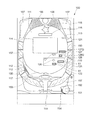
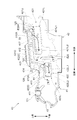
図1は、本実施の形態に係るパチンコ遊技機100の概略正面図である。
なお、以下の説明において、図1に示すパチンコ遊技機100の紙面手前側(遊技者側)を「前側」と称し、紙面奥側(遊技者とは反対側)を「後側」と称する。また、図1に示すパチンコ遊技機100の前側および後側の方向を「前後方向」と呼ぶ。
さらに、図1に示すパチンコ遊技機100の紙面左側を「左側」と称し、紙面右側を「右側」と称する。また、図1に示すパチンコ遊技機100の左側および右側の方向を「左右方向」と呼ぶ。
さらにまた、図1に示すパチンコ遊技機100の紙面上側を「上側」と称し、紙面下側を「下側」と称する。また、図1に示すパチンコ遊技機100の上側および下側の方向を「上下方向」と呼ぶ。
Embodiments of the present invention will be described below in detail with reference to the accompanying drawings.
[Basic configuration of gaming machine]
FIG. 1 is a schematic front view of a pachinko gaming machine 100 according to the present embodiment.
In the following description, the front side (player side) of the pachinko gaming machine 100 shown in FIG. In addition, the front and rear directions of the pachinko gaming machine 100 shown in FIG.
Further, the left side of the pachinko gaming machine 100 shown in FIG. 1 is referred to as “left side”, and the right side of the page is referred to as “right side”. Further, the left and right directions of the pachinko gaming machine 100 shown in FIG.
Furthermore, the upper side of the page of the pachinko gaming machine 100 shown in FIG. 1 is referred to as “upper side”, and the lower side of the page is referred to as “lower side”. Further, the upper and lower directions of the pachinko gaming machine 100 shown in FIG. 1 are referred to as “vertical direction”.

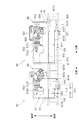
図1に示すように、パチンコ遊技機100(遊技機の一例)は、遊技者の指示操作により打ち出された遊技球が入賞すると賞球を払い出すように構成されたものである。このパチンコ遊技機100は、遊技球が打ち出される遊技盤110と、遊技盤110を囲む枠部材150とを備えている。遊技盤110は、枠部材150に着脱自在に取り付けられている。   As shown in FIG. 1, a pachinko gaming machine 100 (an example of a gaming machine) is configured to pay out a prize ball when a game ball launched by an instruction operation by a player wins. The pachinko gaming machine 100 includes a game board 110 on which game balls are launched, and a frame member 150 surrounding the game board 110. The game board 110 is detachably attached to the frame member 150.

遊技盤110は、前面に、遊技球により遊技を行うための遊技領域111と、下方から発射された遊技球が上昇して遊技領域111の上部位置へ向かう通路を形成するレール部材112と、遊技領域111の右側に遊技球を案内する案内部材113とを備えている。
本実施の形態では、遊技者により視認され易い遊技領域111の位置に、演出のための各種の画像を表示する画像表示部114が配設されている。この画像表示部114は、液晶ディスプレイ等による表示画面を備え、遊技者によるゲームの進行に伴い、例えば、図柄抽選結果(図柄変動結果)を遊技者に報知するための装飾図柄を表示したり、キャラクタの登場やアイテムの出現による演出画像や後述の保留表示を用いた演出画像を表示したりする。
また、遊技盤110の前面に、各種の演出に用いられる可動役物115および盤ランプ116を備えている。可動役物115は、遊技盤110上で動作することにより各種の演出を行い、また、盤ランプ116は、発光することで各種の演出を行う。
The game board 110 has, on the front, a game area 111 for playing with a game ball, a rail member 112 that forms a passage where a game ball launched from below rises toward the upper position of the game area 111, and a game A guide member 113 for guiding the game ball is provided on the right side of the region 111.
In the present embodiment, an image display unit 114 that displays various images for production is provided at a position of the game area 111 that is easily visible to the player. The image display unit 114 includes a display screen such as a liquid crystal display, and displays a decorative symbol for notifying the player of a symbol lottery result (symbol variation result), for example, as the game progresses by the player. An effect image by the appearance of a character or the appearance of an item or an effect image using a later-described hold display is displayed.
In addition, a movable accessory 115 and a board lamp 116 used for various effects are provided on the front surface of the game board 110. The movable accessory 115 performs various effects by operating on the game board 110, and the board lamp 116 performs various effects by emitting light.

遊技領域111には、遊技球が落下する方向に変化を与えるための図示しない遊技くぎおよび風車等が配設されている。また、遊技領域111には、入賞や抽選に関する種々の役物が所定の位置に配設されている。また、遊技領域111には、遊技領域111に打ち出された遊技球のうち入賞口に入賞しなかったものを遊技領域111の外に排出する排出口117が配設されている。   The game area 111 is provided with a game nail and a windmill (not shown) for changing the direction in which the game ball falls. Further, in the game area 111, various bonuses relating to winning and lottery are arranged at predetermined positions. In addition, the game area 111 is provided with a discharge port 117 through which game balls launched into the game area 111 that have not been won in the winning area are discharged out of the game area 111.

本実施の形態では、入賞や抽選に関する種々の役物として、遊技球が入賞すると特別図柄抽選(大当たり抽選)が始動する第1始動口121および第2始動口122と、遊技球が通過すると普通図柄抽選(開閉抽選)が始動する始動ゲート(以下、単にゲートと呼ぶ)124と、が遊技盤110に配設されている。また、ここにいう第1始動口121および第2始動口122とは、予め定められた1の特別図柄表示器の作動契機となる入賞口をいう。具体的には、第1始動口121および第2始動口122には、入賞の際に遊技球の通過を検知するスイッチ(後述の第1始動口スイッチ211および第2始動口スイッチ212)が設けられている。そして、第1始動口121または第2始動口122に遊技球が入賞した際にこのスイッチが遊技球の通過を検知することが、特別図柄表示器を作動させる契機となる。   In the present embodiment, as various functions related to winning and lottery, a special symbol lottery (a jackpot lottery) starts when a game ball wins, and it is normal when a game ball passes. A start gate (hereinafter simply referred to as a gate) 124 for starting a symbol lottery (open / close lottery) is disposed on the game board 110. Moreover, the 1st starting port 121 and the 2nd starting port 122 here say the winning opening used as the operation opportunity of the predetermined 1 special symbol display. Specifically, the first start port 121 and the second start port 122 are provided with switches (a first start port switch 211 and a second start port switch 212 described later) that detect the passage of a game ball when winning a prize. It has been. And when a game ball wins the 1st starting port 121 or the 2nd starting port 122, this switch will detect the passage of a gaming ball as an opportunity to operate a special symbol display.

そして、図1に示すように、本実施の形態の第1始動口121は、遊技領域111の左右方向における中央部に設けられている。また、本実施の形態の第2始動口122は、遊技領域111における右側領域に設けられている。さらに、本実施の形態のゲート124は、遊技領域111における右側領域に設けられている。   And as shown in FIG. 1, the 1st start port 121 of this Embodiment is provided in the center part in the left-right direction of the game area | region 111. As shown in FIG. Further, the second start port 122 of the present embodiment is provided in the right region in the game region 111. Further, the gate 124 of the present embodiment is provided in the right region in the game region 111.

本実施の形態の第2始動口122は、板状に形成され、電動ソレノイドにより開閉する第2始動口扉61を備えている。第2始動口扉61は、普通図柄抽選に当選すると、規定時間(例えば0.15秒ないし1.8秒間)および規定回数(例えば1回ないし3回)だけ開く。そして、第2始動口扉61は、閉じている閉状態の場合に、第2始動口122に遊技球を入り難くし、開いている開状態の場合に、第2始動口122に遊技球が入り易くする。
なお、第2始動口122および第2始動口扉61の構造については、後に詳しく説明する。
The second start port 122 of the present embodiment is formed in a plate shape and includes a second start port door 61 that is opened and closed by an electric solenoid. When the normal start lottery is won, the second start door 61 opens for a specified time (for example, 0.15 to 1.8 seconds) and a specified number of times (for example, 1 to 3 times). The second starter door 61 makes it difficult for a game ball to enter the second starter port 122 when the second starter door 61 is in the closed state. Make it easy to enter.
The structures of the second start port 122 and the second start port door 61 will be described in detail later.

そして、本実施の形態において、遊技領域111における左側領域に遊技球を供給すると、遊技球は、第2始動口122に向けては流れ難く、第1始動口121に向けて流れ易くなっている。一方、遊技領域111における右側領域に遊技球を供給すると、遊技球は、第1始動口121に向けては流れ難く、ゲート124および第2始動口122に向けて流れ易くなっている。   In the present embodiment, when a game ball is supplied to the left region of the game region 111, the game ball is less likely to flow toward the second start port 122 and more easily flows toward the first start port 121. . On the other hand, when a game ball is supplied to the right area in the game area 111, the game ball is less likely to flow toward the first start port 121, and more easily flows toward the gate 124 and the second start port 122.

パチンコ遊技機100は、遊技状態として、大当たり抽選の当選確率に基づき、当選確率の低い低確率状態と、低確率状態よりも当選確率の高い高確率状態とを有している。そして、所定の条件に基づいて低確率状態と高確率状態とのいずれかの状態に制御される。なお、上記の低確率状態と高確率状態の他に、特別図柄抽選の当選確率が低確率状態よりも高く高確率状態よりも低い中確率状態を設定することも可能である。この場合、パチンコ遊技機100は、所定の条件に基づいて低確率状態、中確率状態および高確率状態のいずれかの状態に制御される。   The pachinko gaming machine 100 has, as gaming states, a low probability state with a low winning probability and a high probability state with a higher winning probability than the low probability state based on the winning probability of the jackpot lottery. Then, the state is controlled to be either a low probability state or a high probability state based on a predetermined condition. In addition to the low probability state and the high probability state, it is possible to set a medium probability state in which the winning probability of the special symbol lottery is higher than the low probability state and lower than the high probability state. In this case, the pachinko gaming machine 100 is controlled to one of a low probability state, a medium probability state, and a high probability state based on a predetermined condition.

また、パチンコ遊技機100は、第2始動口122への入賞機会が少ない時短無状態と、時短無状態よりも第2始動口122への入賞機会が多い時短状態とを有している。そして、所定の条件において、時短無状態と、時短状態とのいずれかの状態に制御される。時短状態とは、たとえば、特別図柄変動時間および普通図柄変動時間を短縮すること、第2始動口扉61の開時間を延長すること、普通図柄抽選の当たり当選確率を高確率にすること、のいずれか一つまたは複数の組合せによって制御される遊技状態である。   Further, the pachinko gaming machine 100 has a short time state where there are few winning opportunities at the second start port 122 and a short state when there are more winning opportunities at the second start port 122 than in the short time state. Then, under a predetermined condition, the state is controlled to either the timeless state or the timeless state. The short-time state means, for example, shortening the special symbol variation time and the normal symbol variation time, extending the opening time of the second start door 61, and increasing the probability of winning the normal symbol lottery. It is a gaming state controlled by any one or a combination of a plurality.

また、図1に示すように、入賞や抽選に関するその他の役物として、特別図柄抽選の結果に応じて開放する特別電動役物としての第1大入賞口125と、特別図柄抽選の結果に応じて開放する特別電動役物としての第2大入賞口127と、遊技球が入賞しても抽選を行わない普通入賞口126と、が遊技盤110に設けられている。そして、本実施の形態において、図1に示すように、第1大入賞口125および第2大入賞口127は、遊技領域111における右側領域に設けられている。   Moreover, as shown in FIG. 1, according to the result of the special symbol lottery and the first big prize opening 125 as a special electric accessory that is opened according to the result of the special symbol lottery, as other characters related to winning or lottery. The game board 110 is provided with a second grand prize opening 127 as a special electric accessory to be opened and a normal prize opening 126 through which a lottery is not performed even if a game ball is won. In the present embodiment, as shown in FIG. 1, the first big prize opening 125 and the second big prize opening 127 are provided in the right area of the game area 111.

第1大入賞口125には、第1大入賞口125を開閉する第1大入賞口扉51が設けられている。以下の説明において、第1大入賞口扉51の開閉状態や開閉動作のことを、便宜的に、第1大入賞口125の開閉状態や開閉動作として説明する場合がある。
なお、第1大入賞口125および第1大入賞口扉51の構造については、後に詳しく説明する。
The first big prize opening 125 is provided with a first big prize opening door 51 for opening and closing the first big prize opening 125. In the following description, the opening / closing state and opening / closing operation of the first grand prize opening door 51 may be described as the opening / closing state and opening / closing operation of the first big winning opening 125 for convenience.
The structures of the first grand prize opening 125 and the first grand prize opening door 51 will be described in detail later.

第2大入賞口127には、第2大入賞口127を開閉する第2大入賞口扉127Dが設けられている。以下の説明において、第2大入賞口扉127Dの開閉状態や開閉動作のことを、便宜的に、第2大入賞口127の開閉状態や開閉動作として説明する場合がある。
なお、本実施形態の第2大入賞口127は、第1大入賞口125よりも遊技球の流下方向において上流側に配置されている。さらに、第2大入賞口127は、第2始動口122よりも上流側に配置されている。
The second big prize opening 127 is provided with a second big prize opening door 127D for opening and closing the second big prize opening 127. In the following description, the opening / closing state and the opening / closing operation of the second grand prize opening door 127D may be described as the opening / closing state and the opening / closing operation of the second big winning opening 127 for convenience.
In addition, the 2nd big winning opening 127 of this embodiment is arrange | positioned rather than the 1st big winning opening 125 in the flow-down direction of a game ball. Further, the second grand prize winning port 127 is disposed upstream of the second starting port 122.

さらに、本実施の形態のパチンコ遊技機100は、第2大入賞口127の下流側に、特別入賞口128(所定の領域)を備えている。そして、特別入賞口128には、特別入賞口128を開閉する特別入賞口扉128Dが設けられている。なお、本実施の形態では、第2大入賞口127と特別入賞口128とは、単一のユニットにより構成されている。
そして、本実施の形態のパチンコ遊技機100では、第2大入賞口127に入球した遊技球が内部に設けられた所定の経路を流れて特別入賞口128に入球することによって、大当たり遊技後の遊技状態を、遊技者にとって有利な特定の遊技状態(例えば、高確率時短遊技状態)に移行させる。
Further, the pachinko gaming machine 100 according to the present embodiment includes a special prize opening 128 (predetermined area) on the downstream side of the second big prize opening 127. The special prize opening 128 is provided with a special prize opening door 128D for opening and closing the special prize opening 128. In the present embodiment, the second big prize opening 127 and the special prize opening 128 are constituted by a single unit.
Then, in the pachinko gaming machine 100 of the present embodiment, the game balls that have entered the second grand prize opening 127 flow through a predetermined route provided inside and enter the special prize opening 128, so that the big hit game The later game state is shifted to a specific game state advantageous to the player (for example, a high probability short-time game state).

なお、本実施の形態において、遊技領域111における右側領域に遊技球を供給すると、遊技球は、第1大入賞口125および第2大入賞口127に向けて流れ易くなっている。つまり、実施の形態においては、遊技領域111における左側領域に遊技球を供給しても、遊技球は、第1大入賞口125および第2大入賞口127に入球しないように構成している。   In the present embodiment, when a game ball is supplied to the right area of the game area 111, the game ball easily flows toward the first big prize opening 125 and the second big prize opening 127. In other words, in the embodiment, even if a game ball is supplied to the left area in the game area 111, the game ball is configured not to enter the first big prize opening 125 and the second big prize opening 127. .

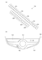
また、本実施の形態では、遊技盤110の左下の位置に、抽選結果や保留数に関する表示を行う表示器130が配設されている。   In the present embodiment, a display 130 for displaying the lottery result and the number of holds is arranged at the lower left position of the game board 110.

また、遊技盤110の裏面には、特別図柄の当選の判定等を行う遊技制御基板、演出を統括的に制御する演出制御基板、画像および音による演出を制御する画像制御基板、各種のランプおよび可動役物115による演出を制御するランプ制御基板などの図示しない各種の基板等が取り付けられる。また、遊技盤110の裏面には、供給された24VのAC電源をDC電源に変換して各種の基板等に出力するスイッチング電源(不図示)が配設されている。   Also, on the back side of the game board 110, a game control board that determines whether or not a special symbol is won, an effect control board that comprehensively controls effects, an image control board that controls effects by images and sounds, various lamps, Various substrates (not shown) such as a lamp control substrate for controlling the effect by the movable accessory 115 are attached. In addition, a switching power supply (not shown) that converts the supplied 24V AC power source into a DC power source and outputs it to various boards and the like is disposed on the back surface of the game board 110.

枠部材150は、遊技者がハンドル151に触れてレバー152を時計方向に回転させる操作を行うとその操作角度に応じた打球力にて遊技球を所定の時間間隔(例えば1分間に100個)で電動発射する発射装置(不図示)を備えている。また、枠部材150は、遊技者のレバー152による操作と連動したタイミングで発射装置に遊技球を1つずつ順に供給する供給装置(不図示)と、供給装置が発射装置に供給する遊技球を一時的に溜めておく皿153と、を備えている。この皿153には、例えば払い出しユニットによる払出球が払い出される。
なお、本実施の形態では、皿153を上下皿一体で構成しているが、上皿と下皿とを分離する構成例も考えられる。また、発射装置のハンドル151を所定条件下で発光させる構成例も考えられる。
When the player touches the handle 151 and rotates the lever 152 in the clockwise direction, the frame member 150 moves the game balls at a predetermined time interval (for example, 100 per minute) with a hitting force according to the operation angle. And a launching device (not shown) for electrically firing. In addition, the frame member 150 includes a supply device (not shown) that sequentially supplies game balls to the launching device one by one at a timing in conjunction with the operation of the player's lever 152, and a game ball that the supply device supplies to the launching device. And a plate 153 for temporarily storing. For example, a payout ball by a payout unit is paid out to the plate 153.
In the present embodiment, the plate 153 is configured as an integrated upper and lower plate, but a configuration example in which the upper plate and the lower plate are separated is also conceivable. A configuration example in which the handle 151 of the launching device emits light under a predetermined condition is also conceivable.

また、枠部材150は、発射装置のハンドル151に遊技者が触れている状態であっても遊技球の発射を一時的に停止させるための停止ボタン154と、皿153に溜まっている遊技球を箱(不図示)に落下させて取り出すための取り出しボタン155と、を備えている。
また、枠部材150は、パチンコ遊技機100の遊技状態や状況を告知したり各種の演出を行ったりするスピーカ156および枠ランプ157を備えている。スピーカ156は、楽曲や音声、効果音による各種の演出を行う。枠ランプ157は、LED等の発光体で構成され、点灯・点滅によるパターンや発光色の違い等で光による各種の演出を行う。なお、枠ランプ157については、光の照射方向を変更する演出を行うことを可能にする構成例が考えられる。
また、枠部材150は、遊技盤110を遊技者と隔てるための透明板(不図示)を備えている。
The frame member 150 also includes a stop button 154 for temporarily stopping the launch of the game ball even when the player is touching the handle 151 of the launch device, and a game ball stored in the tray 153. A take-out button 155 for dropping and taking out the box (not shown).
Further, the frame member 150 includes a speaker 156 and a frame lamp 157 for notifying the gaming state and situation of the pachinko gaming machine 100 and performing various effects. The speaker 156 performs various effects using music, voice, and sound effects. The frame lamp 157 is composed of a light emitting body such as an LED, and performs various effects by light depending on a pattern due to lighting and blinking, a difference in emission color, and the like. In addition, about the frame lamp 157, the structural example which enables performing the effect which changes the irradiation direction of light can be considered.
The frame member 150 also includes a transparent plate (not shown) for separating the game board 110 from the player.

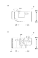
図2は、本実施の形態に係るパチンコ遊技機100を説明する図であり、図2(a)は、遊技盤110の左下に配設された表示器130の一例を示す拡大図であり、図2(b)は、パチンコ遊技機100の部分平面図である。
パチンコ遊技機100の表示器130は、図2(a)に示すように、第1始動口121の入賞に対応して作動する第1特別図柄表示器221と、第2始動口122の入賞に対応して作動する第2特別図柄表示器222と、ゲート124の通過に対応して作動する普通図柄表示器223と、を備えている。第1特別図柄表示器221は、第1始動口121の入賞に基づき、特別図柄を変動表示した後に停止表示させて抽選結果を表示する。第2特別図柄表示器222は、第2始動口122の入賞に基づき、特別図柄を変動表示した後に停止表示させて抽選結果を表示する。普通図柄表示器223は、遊技球がゲート124を通過したことに基づき、普通図柄を変動表示した後に停止表示させて抽選結果を表示する。本実施の形態では、第1特別図柄表示器221、第2特別図柄表示器222は、各々LEDを配列した表示装置で構成され、その点灯態様によって特別図柄抽選の抽選結果が表示される。同様に、普通図柄表示器223も、LEDを配列した表示装置で構成され、その点灯態様によって普通図柄抽選の抽選結果が表示される。
FIG. 2 is a diagram for explaining the pachinko gaming machine 100 according to the present embodiment, and FIG. 2A is an enlarged view showing an example of the display unit 130 arranged at the lower left of the gaming board 110. FIG. 2B is a partial plan view of the pachinko gaming machine 100.
As shown in FIG. 2A, the display 130 of the pachinko gaming machine 100 receives a first special symbol display 221 that operates in response to winning of the first starting port 121 and a winning of the second starting port 122. A second special symbol display 222 that operates correspondingly and a normal symbol display 223 that operates corresponding to the passage of the gate 124 are provided. The first special symbol display 221 displays the lottery result by stopping and displaying the special symbol on the basis of the winning of the first start port 121 after variably displaying. The second special symbol display 222 displays the lottery result by stopping and displaying the special symbol based on the winning of the second start port 122 after variably displaying. Based on the fact that the game ball has passed through the gate 124, the normal symbol display unit 223 displays the lottery result by stopping and displaying the normal symbol after being variably displayed. In the present embodiment, the first special symbol display 221 and the second special symbol display 222 are each constituted by a display device in which LEDs are arranged, and the lottery result of the special symbol lottery is displayed according to the lighting mode. Similarly, the normal symbol display 223 is also composed of a display device in which LEDs are arranged, and the lottery result of the normal symbol lottery is displayed according to the lighting mode.

また、表示器130は、第1特別図柄表示器221での保留に対応して作動する第1特別図柄保留表示器218と、第2特別図柄表示器222での保留に対応して作動する第2特別図柄保留表示器219と、普通図柄表示器223での保留に対応して作動する普通図柄保留表示器220と、を備えている。本実施の形態では、第1特別図柄保留表示器218、第2特別図柄保留表示器219および普通図柄保留表示器220は、各々LEDを配列した表示装置で構成され、その点灯態様によって保留数が表示される。   In addition, the indicator 130 operates in response to the hold in the first special symbol display 221 and the first special symbol hold indicator 218 that operates corresponding to the hold in the first special symbol display 221 and the second special symbol display 222. 2 a special symbol hold indicator 219 and a normal symbol hold indicator 220 that operates in response to the hold in the normal symbol indicator 223. In the present embodiment, the first special symbol hold indicator 218, the second special symbol hold indicator 219, and the normal symbol hold indicator 220 are each configured by a display device in which LEDs are arranged, and the number of holds is determined depending on the lighting mode. Is displayed.

ここで、保留について説明する。特別図柄の変動表示動作中(入賞1回分の変動表示が行なわれている間)にさらに第1始動口121または第2始動口122に遊技球が入賞した場合、特別図柄が変動中であるために、後の入賞に基づく特別図柄の変動表示動作を開始することができない。そのため、後の入賞は規定個数(例えば4個)を限度に記憶され、その入賞した遊技球に対する特別図柄を始動させるための権利が、先に入賞した遊技球に対する変動表示動作が終了するまで、保留される。
なお、普通図柄に関しても、特別図柄と同様の処理を行う。このような保留がなされていることおよびその保留の数(未変動数)が、第1特別図柄保留表示器218、第2特別図柄保留表示器219および普通図柄保留表示器220に表示される。
Here, the hold will be described. If a game ball wins in the first start port 121 or the second start port 122 during the special symbol change display operation (while the change display for one win is being performed), the special symbol is changing. In addition, the special symbol variation display operation based on the subsequent winning cannot be started. Therefore, the number of subsequent winnings is memorized up to a specified number (for example, 4), and the right to start a special symbol for the winning game ball is until the variable display operation for the previously winning game ball ends. Deferred.
For normal symbols, the same processing as for special symbols is performed. The fact that such a hold has been made and the number of hold (unchanged number) are displayed on the first special symbol hold indicator 218, the second special symbol hold indicator 219 and the normal symbol hold indicator 220.

さらに、表示器130は、パチンコ遊技機100の状態を表示する状態表示器224を備えている。本実施の形態では、状態表示器224は、3個のLEDを配列した表示装置で構成されている。3個のLEDのうち1つは、パチンコ遊技機100の状態が、特別図柄抽選の当選確率が高確率である高確率状態となっているか否かを点灯により報知するものである。また、他の1つは、パチンコ遊技機100の状態が、第2始動口122に入賞しやすい時短状態となっているか否かを点灯により報知するものである。さらに他の1つは、右打ちすることによって(遊技球の打球力を変更することによって)遊技者に有利な状態となっているか否かを点灯により報知するものである。   Furthermore, the display device 130 includes a state display device 224 that displays the state of the pachinko gaming machine 100. In the present embodiment, the status indicator 224 is configured by a display device in which three LEDs are arranged. One of the three LEDs notifies whether or not the state of the pachinko gaming machine 100 is in a high probability state where the winning probability of the special symbol lottery is high. The other one is to notify by lighting whether the state of the pachinko gaming machine 100 is in a short time state in which it is easy to win a prize at the second start port 122. Still another one is to notify by lighting whether or not the player is in a state advantageous to the player by making a right strike (by changing the hitting force of the game ball).

なお、状態表示器224が表示するパチンコ遊技機100の状態は上記の例に限らず、他の状態を表示することができる。例えばパチンコ遊技機100の状態として低確率状態よりも当選確率が高く高確率状態よりは当選確率が低い中確率状態が設定される場合、状態表示器224は、中確率状態となっているか否かを点灯により報知しても良い。   The state of the pachinko gaming machine 100 displayed by the state display 224 is not limited to the above example, and other states can be displayed. For example, when the state of the pachinko gaming machine 100 is set to a medium probability state in which the winning probability is higher than the low probability state and the winning probability is lower than the high probability state, the state indicator 224 indicates whether or not the state indicator 224 is in the medium probability state. May be notified by lighting.

また、表示器130は、特別図柄抽選の抽選結果に応じて行われる大当たり遊技において第2大入賞口127が作動される際のラウンド数を表示するラウンド数表示器225を備えている。なお、大当たり遊技については後述する。ラウンド数表示器225は、LEDを配列した表示装置で構成され、その点灯態様によって大当たり遊技における第2大入賞口127の作動ラウンド数が表示される。   In addition, the indicator 130 includes a round number indicator 225 for displaying the number of rounds when the second big prize opening 127 is operated in the jackpot game performed according to the lottery result of the special symbol lottery. The jackpot game will be described later. The round number display 225 is composed of a display device in which LEDs are arranged, and the number of operating rounds of the second big winning opening 127 in the jackpot game is displayed according to the lighting mode.

パチンコ遊技機100の枠部材150は、遊技者が演出に対する入力を行うための入力装置を備えている。図2(b)に示すように、本実施の形態では、入力装置の一例として、演出ボタン161と、演出ボタン161に隣接し、略十字に配列された複数のキーからなる演出キー162と、が枠部材150に配設されている。図示の例において、複数の画像の中から1つの画像を選択する操作を受け付ける演出を行う場合を考える。この場合、例えば、遊技者が十字に配列された4つのキーからなる演出キー162を操作することにより、画像表示部114に表示されている複数の画像のいずれかを指示し、演出ボタン161を操作することにより、指示した画像を選択するような演出を行うことができる。また、入力装置の形態としては、図示した演出ボタン161および演出キー162の他、レバーやダイヤル等、演出の内容等に応じて様々な入力形態を採用することができる。   The frame member 150 of the pachinko gaming machine 100 includes an input device for a player to input an effect. As shown in FIG. 2B, in the present embodiment, as an example of an input device, an effect button 161, an effect key 162 that is adjacent to the effect button 161 and includes a plurality of keys arranged in a substantially cross shape, Is disposed on the frame member 150. In the example shown in the figure, a case is considered where an effect of accepting an operation of selecting one image from a plurality of images is performed. In this case, for example, when the player operates an effect key 162 including four keys arranged in a cross, one of a plurality of images displayed on the image display unit 114 is instructed, and the effect button 161 is pressed. By performing the operation, it is possible to produce an effect of selecting the instructed image. In addition to the effect buttons 161 and the effect keys 162 shown in the figure, various input forms such as levers, dials, and the like can be adopted as the input device.

〔制御ユニットの構成〕
次に、パチンコ遊技機100での動作制御や信号処理を行う制御ユニットについて説明する。
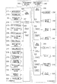
図3は、本実施の形態のパチンコ遊技機の制御ユニットの内部構成を示すブロック図である。
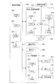
図4は、本実施の形態の画像/音響制御部およびランプ制御部の説明図である。
[Configuration of control unit]
Next, a control unit that performs operation control and signal processing in the pachinko gaming machine 100 will be described.
FIG. 3 is a block diagram showing an internal configuration of the control unit of the pachinko gaming machine according to the present embodiment.
FIG. 4 is an explanatory diagram of the image / sound control unit and the lamp control unit of the present embodiment.

図3に示すように、制御ユニットは、メイン制御手段として、特別図柄の当選の判定等を行う遊技制御部200を備えている。また、サブ制御手段として、演出を統括的に制御する演出制御部300と、払出球の払い出し制御を行う払出制御部330と、を備えている。   As shown in FIG. 3, the control unit includes a game control unit 200 that determines whether a special symbol is won or the like as main control means. In addition, as the sub-control means, an effect control unit 300 that comprehensively controls the effect and a payout control unit 330 that controls payout of the payout ball are provided.

〔遊技制御部の構成・機能〕
遊技制御部200は、特別図柄の当選の判定等を行う際の演算処理を行うCPU201と、CPU201にて実行されるプログラムや各種データ等が記憶されたROM202と、CPU201の作業用メモリ等として用いられるRAM203と、を備えている。
[Configuration and function of game control unit]
The game control unit 200 is used as a CPU 201 that performs arithmetic processing when determining whether or not a special symbol is won, a ROM 202 that stores programs executed by the CPU 201, various data, and the like, a working memory of the CPU 201, and the like. RAM 203 to be provided.

遊技制御部200は、パチンコ遊技機100の遊技状態を、高確率状態または低確率状態のいずれか、時短無状態または時短状態のいずれかで制御する。これにより、パチンコ遊技機100の遊技状態は、高確率状態および時短状態である高確率時短遊技状態、低確率状態および時短状態である低確率時短遊技状態、高確率状態および時短無状態である高確率時短無遊技状態、低確率状態および時短無状態である低確率時短無遊技状態のいずれかとなる。そして、遊技制御部200は、所定の条件に基づき、高確率状態と低確率状態とを切り替え、時短無状態と時短状態とを切り替える。また、遊技制御部200は、時短状態において、時短無状態よりも普通図柄抽選の当たり当選確率を高確率にする、普通図柄変動時間を短縮する、第2始動口扉61の開時間を延長する等の制御を行う。   The game control unit 200 controls the gaming state of the pachinko gaming machine 100 in either a high probability state or a low probability state, a time-short state or a time-short state. As a result, the gaming state of the pachinko gaming machine 100 is a high probability state and a short time state, a high probability short time gaming state, a low probability state and a short time state, low probability short time gaming state, a high probability state, and a short time short state. It is one of a short-probability state with no probability, a low-probability state, and a short-probability state with a low probability. Then, the game control unit 200 switches between the high probability state and the low probability state based on a predetermined condition, and switches between the short time state and the short time state. In addition, the game control unit 200 increases the probability of winning the normal symbol lottery in the short time state, shortens the normal symbol variation time, and extends the opening time of the second start door 61 in the short time state. Etc. are controlled.

遊技制御部200は、第1始動口121または第2始動口122に遊技球が入賞したことを契機として特別図柄抽選を行う。そして、遊技制御部200は、特別図柄抽選の判定結果に応じて大当たり遊技等の特別遊技を行う。特別遊技において、遊技制御部200は、特別電動役物である第2大入賞口127が所定条件(例えば29.5秒経過または遊技球6個の入賞)を満たすまで開状態を維持するラウンドを所定回数だけ繰り返すように制御する。そして、遊技制御部200は、第2大入賞口127が開く際の開閉動作間隔を制御する。また、遊技制御部200は、特別図柄抽選の判定結果に応じて小当たり遊技を行う。小当たり遊技において、遊技制御部200は、第1大入賞口125が所定条件を満たすまで開状態を維持するように制御する。そして、遊技制御部200は、第1大入賞口125が開く際の開閉動作間隔を制御する。   The game control unit 200 performs a special symbol lottery when the game ball is won at the first start port 121 or the second start port 122. And the game control part 200 performs special games, such as a jackpot game, according to the determination result of a special symbol lottery. In the special game, the game control unit 200 performs a round of maintaining an open state until the second big prize opening 127, which is a special electric accessory, satisfies a predetermined condition (for example, 29.5 seconds have passed or 6 game balls have been won). Control to repeat a predetermined number of times. And the game control part 200 controls the opening / closing operation | movement space | interval at the time of the 2nd big winning opening 127 opening. In addition, the game control unit 200 plays a small hit game according to the determination result of the special symbol lottery. In the small hit game, the game control unit 200 performs control so that the first big prize opening 125 is kept open until a predetermined condition is satisfied. And the game control part 200 controls the opening-and-closing operation space | interval at the time of the 1st big winning opening 125 opening.

また、遊技制御部200は、ゲート124を遊技球が通過したことを契機として普通図柄抽選を行う。そして、普通図柄抽選の判定結果に応じて第2始動口扉61の作動を制御する。
また、遊技制御部200は、特別図柄変動中に遊技球が第1始動口121または第2始動口122へ入賞したことにより発生する保留や、普通図柄変動中に遊技球がゲート124を通過したことにより発生する保留の設定を行う。
さらに、遊技制御部200は、特別図柄抽選および普通図柄抽選の判定結果、高確率状態と低確率状態の変更情報、時短無状態と時短状態の変更情報、保留の設定情報等の遊技制御に伴う情報を、後述するコマンドにより演出制御部300に送る。
In addition, the game control unit 200 performs a normal symbol lottery when the game ball passes through the gate 124. Then, the operation of the second start door 61 is controlled according to the determination result of the normal symbol lottery.
In addition, the game control unit 200 holds the game ball when the game ball wins the first start port 121 or the second start port 122 during the special symbol change, or the game ball passes through the gate 124 during the normal symbol change. Set the hold that occurs.
Further, the game control unit 200 accompanies the game control such as the determination result of the special symbol lottery and the normal symbol lottery, the change information of the high probability state and the low probability state, the change information of the time short state and the short time state, the setting information of the hold, etc. Information is sent to the production control unit 300 by a command to be described later.

さらに、遊技制御部200は、第1始動口121、第2始動口122、第1大入賞口125、第2大入賞口127および普通入賞口126に遊技球が入賞すると、遊技球が入賞した場所に応じて1つの遊技球当たり所定数の賞球を払い出すように、払出制御部330に対する指示を行う。例えば、第1始動口121に遊技球が入賞すると3個の賞球、第2始動口122に遊技球が入賞すると4個の賞球、第1大入賞口125に遊技球が入賞すると12個の賞球、第2大入賞口127に遊技球が入賞すると12個の賞球、普通入賞口126に遊技球が入賞すると10個の賞球をそれぞれ払い出すように、払出制御部330に指示命令(コマンド)を送る。なお、ゲート124を遊技球が通過したことを検出しても、それに連動した賞球の払い出しは払出制御部330に指示しない。
払出制御部330が遊技制御部200の指示に従って賞球の払い出しを行った場合には、遊技制御部200は、払い出した賞球の個数に関する情報を払出制御部330から取得する。それにより、払い出した賞球の個数を管理する。
Furthermore, the game control unit 200 wins the game ball when the game ball wins at the first start port 121, the second start port 122, the first big winning port 125, the second big winning port 127, and the normal winning port 126. The payout control unit 330 is instructed to pay out a predetermined number of prize balls per game ball according to the place. For example, when a game ball wins at the first start port 121, three prize balls, when a game ball wins at the second start port 122, four prize balls, and when a game ball wins the first big prize port 125, twelve balls. The payout control unit 330 is instructed to pay out 12 award balls when a game ball is won at the second big prize opening 127 and 10 award balls when a game ball wins at the normal prize opening 126. Send an instruction (command). Even if it is detected that the game ball has passed through the gate 124, the payout control unit 330 is not instructed to pay out the prize ball in conjunction therewith.
When the payout control unit 330 pays out a prize ball in accordance with an instruction from the game control unit 200, the game control unit 200 acquires information on the number of prize balls paid out from the payout control unit 330. As a result, the number of prize balls paid out is managed.

遊技制御部200には、検知手段として、図3に示すように、第1始動口121への遊技球の入賞を検出する第1始動口検出部(第1始動口スイッチ(SW))211と、第2始動口122への遊技球の入賞を検出する第2始動口検出部(第2始動口スイッチ(SW))212と、第2始動口扉61を開閉する第2始動口扉開閉部60と、ゲート124への遊技球の通過を検出するゲート検出部(ゲートスイッチ(SW))214と、が接続されている。   As shown in FIG. 3, the game control unit 200 includes a first start port detection unit (first start port switch (SW)) 211 that detects a winning of a game ball to the first start port 121, as shown in FIG. , A second start port detecting unit (second start port switch (SW)) 212 for detecting the winning of a game ball to the second start port 122, and a second start port door opening / closing unit for opening and closing the second start port door 61. 60 and a gate detector (gate switch (SW)) 214 for detecting the passage of the game ball to the gate 124 are connected.

さらに、遊技制御部200には、第1大入賞口125への遊技球の入賞を検出する第1大入賞口検出部(第1大入賞口スイッチ(SW))215と、第1大入賞口125の第1大入賞口扉51を閉状態と開状態とにそれぞれ設定する第1大入賞口扉開閉部50と、が接続されている。
また、遊技制御部200には、第2大入賞口127への遊技球の入賞を検出する第2大入賞口検出部(第2始動口スイッチ(SW))226と、第2大入賞口127の第2大入賞口扉127Dを閉状態と開状態とにそれぞれ設定する第2大入賞口扉開閉部227と、が接続されている。
さらにまた、遊技制御部200には、特別入賞口128への遊技球の入賞を検出する特別入賞口検出部(特別入賞口スイッチ(SW))228と、特別入賞口128の特別入賞口扉128Dを閉状態と開状態とに設定する特別入賞口扉開閉部229と、が接続されている。
そして、遊技制御部200には、普通入賞口126への遊技球の入賞を検出する普通入賞口検出部(普通入賞口スイッチ(SW))217と、が接続されている。
Further, the game control unit 200 includes a first grand prize port detection unit (first grand prize port switch (SW)) 215 that detects a winning of a game ball to the first grand prize port 125, and a first grand prize port. A first grand prize opening door opening / closing part 50 for setting the 125 first big prize opening doors 51 to a closed state and an open state, respectively, is connected.
In addition, the game control unit 200 includes a second grand prize port detection unit (second start port switch (SW)) 226 that detects a winning of a game ball to the second grand prize port 127, and a second grand prize port 127. And a second grand prize opening door opening / closing part 227 for setting the second big prize opening door 127D to a closed state and an open state, respectively.
Furthermore, the game control unit 200 includes a special winning port detecting unit (special winning port switch (SW)) 228 for detecting the winning of a game ball in the special winning port 128, and a special winning port door 128D of the special winning port 128. Is connected to a special winning opening door opening / closing part 229 that sets the closed state and the open state.
The game control unit 200 is connected to a normal winning port detection unit (normal winning port switch (SW)) 217 that detects a winning of a game ball to the normal winning port 126.

また、遊技制御部200には、特別図柄の変動中に第1始動口121へ入賞した未変動分の保留個数を表示する第1特別図柄保留表示器218と、特別図柄の変動中に第2始動口122へ入賞した未変動分の保留個数を表示する第2特別図柄保留表示器219と、普通図柄の変動中にゲート124を通過した未変動分の保留個数を表示する普通図柄保留表示器220と、が接続されている。
さらに、遊技制御部200には、第1始動口121への遊技球の入賞により行われる特別図柄の変動表示および特別図柄抽選の結果を表示する第1特別図柄表示器221と、第2始動口122への遊技球の入賞により行われる特別図柄の変動表示および特別図柄抽選の結果を表示する第2特別図柄表示器222と、普通図柄の変動表示および普通図柄抽選の結果を表示する普通図柄表示器223と、パチンコ遊技機100の状態を表示する状態表示器224と、が接続されている。
In addition, the game control unit 200 includes a first special symbol hold indicator 218 for displaying the number of unreserved reserves won in the first start port 121 during the change of the special symbol, and the second special symbol hold indicator 218 during the change of the special symbol. A second special symbol hold indicator 219 that displays the number of unchanged reserves that have been won at the start port 122, and a normal symbol hold indicator that displays the number of unchanged symbols that have passed through the gate 124 while the normal symbol is changing. 220 are connected.
Further, the game control unit 200 includes a first special symbol display 221 for displaying a special symbol variation display and a special symbol lottery result performed by winning a game ball in the first starting port 121, and a second starting port. The second special symbol display 222 that displays the result of the special symbol variation display and special symbol lottery performed by winning the game ball to 122, and the normal symbol display that displays the normal symbol variation display and the normal symbol lottery result A device 223 and a state indicator 224 for displaying the state of the pachinko gaming machine 100 are connected.

そして、第1始動口スイッチ211、第2始動口スイッチ212、ゲートスイッチ214、第1大入賞口スイッチ215、第2大入賞口スイッチ226、特別入賞口スイッチ228および普通入賞口スイッチ217にて検出された検出信号が、遊技制御部200に送られる。
また、遊技制御部200からの制御信号が、第1大入賞口扉開閉部50、第2始動口扉開閉部60、第2大入賞口扉開閉部227、特別入賞口扉開閉部229、第1特別図柄保留表示器218、第2特別図柄保留表示器219、普通図柄保留表示器220、第1特別図柄表示器221、第2特別図柄表示器222、普通図柄表示器223および状態表示器224に送られる。
これらにより、遊技制御部200は、上記した払い出し賞球数に関連する各種制御を行う。
Then, the first start port switch 211, the second start port switch 212, the gate switch 214, the first big prize port switch 215, the second big prize port switch 226, the special prize port switch 228 and the normal prize port switch 217 are detected. The detected signal is sent to the game control unit 200.
In addition, the control signals from the game control unit 200 are the first grand prize opening door opening / closing part 50, the second start opening door opening / closing part 60, the second big winning opening door opening / closing part 227, the special winning opening door opening / closing part 229, 1 special symbol hold indicator 218, second special symbol hold indicator 219, normal symbol hold indicator 220, first special symbol indicator 221, second special symbol indicator 222, normal symbol indicator 223, and status indicator 224 Sent to.
Accordingly, the game control unit 200 performs various controls related to the above-mentioned payout prize ball number.

さらに、遊技制御部200には、ホールに設置されたホストコンピュータ(不図示)に対して各種の情報を送信する盤用外部情報端子基板350が接続されている。そして、遊技制御部200は、払出制御部330から取得した、払い出した賞球数に関する情報や遊技制御部200の状態等を示す情報を、盤用外部情報端子基板350を介してホストコンピュータに送信する。   Further, a board external information terminal board 350 for transmitting various information to a host computer (not shown) installed in the hall is connected to the game control unit 200. Then, the game control unit 200 transmits the information about the number of paid-out prize balls acquired from the payout control unit 330 and the information indicating the state of the game control unit 200 to the host computer via the board external information terminal board 350. To do.

〔払出制御部の構成・機能〕
払出制御部330は、払出球の払い出しを制御する際の演算処理を行うCPU331と、CPU331にて実行されるプログラムや各種データ等が記憶されたROM332と、CPU331の作業用メモリ等として用いられるRAM333と、を備えている。
そして、払出制御部330は、遊技制御部200から送られたコマンドに基づいて、払出球の払い出しを制御する。
具体的には、払出制御部330は、遊技制御部200から、遊技球が入賞した場所(第1始動口121等)に応じた所定数の賞球を払い出すコマンドを取得する。そして、コマンドに指定された数だけの賞球を払い出すように払出駆動部334を制御する。ここでの払出駆動部334は、遊技球の貯留部から遊技球を送り出す駆動モータで構成される。
[Configuration and function of payout control unit]
The payout control unit 330 includes a CPU 331 that performs arithmetic processing when controlling payout of payout balls, a ROM 332 that stores programs executed by the CPU 331, various data, and the like, and a RAM 333 that is used as a work memory for the CPU 331 and the like. And.
The payout control unit 330 controls payout of the payout ball based on the command sent from the game control unit 200.
Specifically, the payout control unit 330 acquires, from the game control unit 200, a command for paying out a predetermined number of prize balls according to the place where the game ball has won (the first start port 121 or the like). Then, the payout driving unit 334 is controlled so as to pay out the number of prize balls specified by the command. Here, the payout drive unit 334 is constituted by a drive motor that sends out the game ball from the game ball storage unit.

また、払出制御部330には、払出駆動部334により遊技球の貯留部から実際に払い出された賞球の数を検出する払出球検出部335と、貯留部(不図示)での遊技球の貯留の有無を検出する球有り検出部336と、遊技者が遊技する際に使用する遊技球や払い出された賞球が保持される皿153が満タン状態に有るか否かを検出する満タン検出部337と、が接続されている。そして、払出制御部330は、払出球検出部335、球有り検出部336および満タン検出部337にて検出された検出信号を受け取り、これらの検出信号に応じた所定の処理を行う。
さらに、払出制御部330には、ホールに設置されたホストコンピュータに対して各種の情報を送信する枠用外部情報端子基板340が接続されている。そして、払出制御部330は、例えば払出駆動部334に対して払い出すように指示した賞球数に関する情報や払出球検出部335にて検出された実際に払い出された賞球数に関する情報等を枠用外部情報端子基板340を介してホストコンピュータに送信する。また、遊技制御部200に対しても、同様の情報を送信する。
The payout control unit 330 includes a payout ball detection unit 335 that detects the number of prize balls actually paid out from the game ball storage unit by the payout driving unit 334, and a game ball in the storage unit (not shown). Detecting unit 336 for detecting presence / absence of storage of the game, and detecting whether or not the plate 153 for holding the game ball used when the player plays the game or the paid-out prize ball is full. A full tank detection unit 337 is connected. The payout control unit 330 receives the detection signals detected by the payout ball detection unit 335, the ball presence detection unit 336, and the full tank detection unit 337, and performs predetermined processing according to these detection signals.
Further, the payout control unit 330 is connected to a frame external information terminal board 340 that transmits various types of information to a host computer installed in the hall. Then, the payout control unit 330, for example, information on the number of prize balls instructed to pay out to the payout driving unit 334, information on the number of prize balls actually paid out detected by the payout ball detection unit 335, etc. Is transmitted to the host computer via the frame external information terminal board 340. Also, similar information is transmitted to the game control unit 200.

〔演出制御部の構成・機能〕
演出制御部300は、演出を制御する際の演算処理を行うCPU301と、CPU301にて実行されるプログラムや各種データ等が記憶されたROM302と、CPU301の作業用メモリ等として用いられるRAM303と、日時を計測するリアルタイムクロック(RTC)304と、を備えている。
演出制御部300は、例えば遊技制御部200から送られる特別図柄抽選での当選か否かの判定結果および変動パターンに基づいて、演出内容を設定する。その際、演出ボタン161または演出キー162を用いたユーザからの操作入力を受けて、操作入力に応じた演出内容を設定する場合もある。この場合、例えば演出ボタン161等のコントローラ(不図示)から操作に応じた信号(操作信号)を受け付け、この操作信号により識別される操作内容を演出の設定に反映させる。
また、演出制御部300は、遊技が所定期間中断された場合には、演出の一つとして客待ち用の画面表示の設定を指示する。
さらには、演出制御部300は、遊技制御部200より受信した高確率状態と低確率状態の変更情報、時短無状態と時短状態の変更情報に基づいて演出内容を設定する。
また、演出制御部300は、設定した演出内容の実行を指示するコマンドを画像/音響制御部310およびランプ制御部320に送る。
[Configuration and function of production control unit]
The effect control unit 300 includes a CPU 301 that performs calculation processing when controlling the effect, a ROM 302 that stores programs executed by the CPU 301 and various data, a RAM 303 that is used as a work memory of the CPU 301, and the like. And a real-time clock (RTC) 304 for measuring.
The effect control unit 300 sets the contents of the effect, for example, based on the determination result of whether or not the winning in the special symbol lottery sent from the game control unit 200 and the variation pattern. At that time, in response to an operation input from the user using the effect button 161 or the effect key 162, the effect content corresponding to the operation input may be set. In this case, for example, a signal (operation signal) corresponding to an operation is received from a controller (not shown) such as the effect button 161, and the operation content identified by the operation signal is reflected in the setting of the effect.
In addition, when the game is interrupted for a predetermined period, the effect control unit 300 instructs the setting of the screen display for waiting for a customer as one of the effects.
Furthermore, the production control unit 300 sets the production content based on the change information of the high probability state and the low probability state received from the game control unit 200, and the change information of the short time state and the short time state.
In addition, the effect control unit 300 sends a command for instructing execution of the set effect contents to the image / sound control unit 310 and the lamp control unit 320.

さらに、演出制御部300には、画像および音響を用いた演出を制御する画像/音響制御部310と、各種のランプおよび可動役物115を用いた演出を制御するランプ制御部320と、が接続されている。   Furthermore, the effect control unit 300 is connected to an image / sound control unit 310 that controls an effect using an image and sound, and a lamp control unit 320 that controls an effect using various lamps and the movable accessory 115. Has been.

〔画像/音響制御部の構成・機能〕
画像/音響制御部310は、図4に示すように、演出内容を表現する画像および音響を制御する際の演算処理を行うCPU311と、CPU311にて実行されるプログラムや各種データ等が記憶されたROM312と、CPU311の作業用メモリ等として用いられるRAM313と、VDP(Video Display Processor)314と、CGROM315と、SNDROM316とを備えている。
[Configuration / Function of Image / Sound Control Unit]
As shown in FIG. 4, the image / sound control unit 310 stores an image that expresses the contents of presentation and a CPU 311 that performs arithmetic processing when controlling sound, a program executed by the CPU 311, various data, and the like. A ROM 312, a RAM 313 used as a working memory for the CPU 311, a VDP (Video Display Processor) 314, a CGROM 315, and an SNDROM 316 are provided.

そして、画像/音響制御部310は、演出制御部300から送られたコマンドに基づいて、画像表示部114に表示する画像およびスピーカ156から出力する音響を制御する。
具体的には、CGROM315には、画像表示部114において遊技中に表示する図柄画像や背景画像、遊技者に抽選結果を報知するための装飾図柄、遊技者に予告演出を表示するためのキャラクタやアイテム等といった画像データが記憶されている。また、SNDROM316には、画像データと同期させて、または画像データとは独立にスピーカ156から出力させる楽曲や音声、さらにはジングル等の効果音等といった各種音響データが記憶されている。
CPU311は、演出制御部300から送られた保留数コマンドもしくは変動開始コマンドに基づいて、アニメーションパターンの解析や、描画に関するコマンドをまとめたディスプレイリストの作成、およびディスプレイリストのVDP314への送信などを行う。
Then, the image / sound control unit 310 controls the image displayed on the image display unit 114 and the sound output from the speaker 156 based on the command sent from the effect control unit 300.
Specifically, the CGROM 315 has a symbol image or background image displayed during the game on the image display unit 114, a decorative symbol for notifying the player of the lottery result, a character for displaying a notice effect to the player, Image data such as items is stored. The SND ROM 316 stores various types of acoustic data such as music and sound output from the speaker 156 in synchronization with the image data or independently of the image data, and sound effects such as jingles.
Based on the hold number command or the change start command sent from the effect control unit 300, the CPU 311 performs analysis of the animation pattern, creation of a display list in which commands related to drawing are created, transmission of the display list to the VDP 314, and the like. .

VDP314は、CPU311から受信したディスプレイリストに基づいて、CGROM315やSNDROM316にそれぞれ記憶された画像データや音響データを読み出す。さらには、VDP314は、読み出した画像データを用いて背景画像表示、図柄画像表示、図柄画像変動、およびキャラクタ/アイテム表示等のための描画処理と、読み出した音響データを用いた音声処理とを行う。そして、VDP314は、描画処理された画像データにより画像表示部114での画面表示を制御する。また、VDP314は、音声処理された音響データによりスピーカ156から出力される音響を制御する。
なお、本実施の形態では、VDP314が描画処理に併せて音声処理も行うよう構成しているが、これに限定されず、音声処理を専用で行うプロセッサを別途設けても構わない。
Based on the display list received from the CPU 311, the VDP 314 reads image data and acoustic data stored in the CGROM 315 and SNDROM 316, respectively. Furthermore, the VDP 314 performs drawing processing for background image display, symbol image display, symbol image variation, character / item display, and the like, and audio processing using the read acoustic data, using the read image data. . The VDP 314 controls screen display on the image display unit 114 based on the image data subjected to the drawing process. The VDP 314 controls the sound output from the speaker 156 based on the sound data that has been subjected to sound processing.
In the present embodiment, the VDP 314 is configured to perform audio processing in addition to the drawing processing. However, the present invention is not limited to this, and a processor that performs dedicated audio processing may be provided separately.

〔ランプ制御部の構成・機能〕
ランプ制御部320は、盤ランプ116や枠ランプ157の発光、および可動役物115の動作を制御する際の演算処理を行うCPU321と、CPU321にて実行されるプログラムや各種データ等が記憶されたROM322と、CPU321の作業用メモリ等として用いられるRAM323と、を備えている。
そして、ランプ制御部320は、演出制御部300から送られたコマンドに基づいて、盤ランプ116や枠ランプ157の点灯/点滅や発光色等を制御する。また、可動役物115の動作を制御する。
[Configuration and function of lamp control unit]
The lamp control unit 320 stores a CPU 321 that performs arithmetic processing when controlling the light emission of the panel lamp 116 and the frame lamp 157 and the operation of the movable accessory 115, and programs executed by the CPU 321 and various data. A ROM 322 and a RAM 323 used as a working memory for the CPU 321 are provided.
The lamp control unit 320 controls lighting / flashing of the panel lamp 116 and the frame lamp 157, the emission color, and the like based on the command sent from the effect control unit 300. Further, the operation of the movable accessory 115 is controlled.

具体的には、ランプ制御部320のROM322には、演出制御部300にて設定される演出内容に応じた盤ランプ116や枠ランプ157での点灯/点滅パターンデータおよび発光色パターンデータ(発光パターンデータ)が記憶されている。CPU321は、ROM322に記憶された発光パターンデータの中から、演出制御部300から送られたコマンドに対応したものを選択して読み出す。そして、ランプ制御部320は、読み出した発光パターンデータにより盤ランプ116や枠ランプ157の発光を制御する。
また、ランプ制御部320のROM322には、演出制御部300にて設定される演出内容に応じた可動役物115の動作パターンデータが記憶されている。CPU321は、可動役物115に対しては、読み出した動作パターンデータによりその動作を制御する。
Specifically, the ROM 322 of the lamp control unit 320 stores lighting / flashing pattern data and emission color pattern data (emission pattern) for the panel lamp 116 and the frame lamp 157 according to the production contents set by the production control unit 300. Data) is stored. The CPU 321 selects and reads out the light emission pattern data stored in the ROM 322 corresponding to the command sent from the effect control unit 300. The lamp controller 320 controls the light emission of the panel lamp 116 and the frame lamp 157 based on the read light emission pattern data.
The ROM 322 of the lamp control unit 320 stores operation pattern data of the movable accessory 115 corresponding to the production content set by the production control unit 300. The CPU 321 controls the operation of the movable accessory 115 based on the read operation pattern data.

なお、本実施の形態では、遊技制御部200、演出制御部300、画像/音響制御部310、ランプ制御部320、および払出制御部330各々は、遊技盤110の後面に配設されたメイン基板としての遊技制御基板、サブ基板としての演出制御基板、画像制御基板、ランプ制御基板、および払出制御基板において個別に構成されている。   In the present embodiment, game control unit 200, effect control unit 300, image / sound control unit 310, lamp control unit 320, and payout control unit 330 are each a main board disposed on the rear surface of game board 110. The game control board, the effect control board as the sub board, the image control board, the lamp control board, and the payout control board are individually configured.

〔遊技制御部の機能構成〕
続いて、遊技制御部200の機能構成を説明する。
図5は、遊技制御部200の機能構成を示すブロック図である。図5に示すように、遊技制御部200は、各種抽選処理を実行する機能部として、乱数取得部231と、普通図柄判定部232と、特別図柄変動制御部233と、特別図柄判定部234と、普通図柄変動制御部236と、を備えている。
また、遊技制御部200は、特別図柄変動に伴う処理を実行する機能部として、変動パターン選択部235を備えている。
さらに、遊技制御部200は、各種役物の動作制御や賞球等に関するデータ処理を実行する機能部として、大入賞口動作制御部237と、第2始動口扉動作制御部238と、賞球処理部239と、出力制御部240と、乱数制御部241と、を備えている。
[Functional configuration of game control unit]
Next, the functional configuration of the game control unit 200 will be described.
FIG. 5 is a block diagram showing a functional configuration of the game control unit 200. As shown in FIG. 5, the game control unit 200 includes a random number acquisition unit 231, a normal symbol determination unit 232, a special symbol variation control unit 233, and a special symbol determination unit 234 as functional units that execute various lottery processes. And a normal symbol fluctuation control unit 236.
In addition, the game control unit 200 includes a variation pattern selection unit 235 as a functional unit that executes a process associated with special symbol variation.
Further, the game control unit 200 is a functional unit that executes operation control of various types of objects and data processing related to prize balls, etc. A processing unit 239, an output control unit 240, and a random number control unit 241 are provided.

乱数取得部231は、特別図柄抽選に用いられる乱数値と、普通図柄抽選に用いられる乱数値とを取得する。特別図柄抽選に用いられる乱数値の場合、具体的には、第1始動口121や第2始動口122に遊技球が入賞したことを条件として、乱数の種類ごとに、所定の範囲の数値の中から1つの数値(乱数値)が選択(取得)される。取得された乱数値は、特別図柄判定部234による判定に用いられる。詳しくは後述するが、特別図柄抽選に用いられる乱数としては、大当たりか否かを示す大当たり乱数、大当たりの種類を示す図柄乱数、変動パターン乱数、リーチ乱数等が有る。
また、普通図柄抽選に用いられる乱数値の場合、具体的には、ゲート124を遊技球が通過したことを条件として、所定の範囲の数値の中から1つの数値(乱数値)が選択(取得)される。取得された乱数値は、普通図柄判定部232による判定に用いられる。なお、普通図柄抽選に用いられる乱数としては、当たりか否かを示す当たり乱数の他、当たりの種類を示す図柄乱数や変動パターン乱数等が設定される場合もある。
特別図柄変動制御部233は、特別図柄抽選が行われた場合に、抽選結果に応じて、第1特別図柄表示器221または第2特別図柄表示器222における特別図柄の変動を制御する。
The random number acquisition unit 231 acquires a random number value used for the special symbol lottery and a random value used for the normal symbol lottery. In the case of a random number value used for the special symbol lottery, specifically, on the condition that a game ball has won a prize at the first starting port 121 or the second starting port 122, a numerical value in a predetermined range is obtained for each type of random number. One numerical value (random number value) is selected (obtained) from the inside. The acquired random number value is used for determination by the special symbol determination unit 234. As will be described in detail later, the random numbers used in the special symbol lottery include a jackpot random number indicating whether or not the jackpot, a symbol random number indicating the type of jackpot, a variation pattern random number, a reach random number, and the like.
Further, in the case of a random number value used for the normal symbol lottery, specifically, one numerical value (random number value) is selected (acquired) from a predetermined range of values on condition that the game ball has passed through the gate 124. ) The acquired random number value is used for determination by the normal symbol determination unit 232. In addition, as a random number used for the normal symbol lottery, a symbol random number indicating a winning type, a variation pattern random number, or the like may be set in addition to a winning random number indicating whether or not the winning is made.
When the special symbol lottery is performed, the special symbol fluctuation control unit 233 controls the fluctuation of the special symbol in the first special symbol indicator 221 or the second special symbol indicator 222 according to the lottery result.

特別図柄判定部234は、特別図柄の変動開始時に、図20に示すような乱数テーブルを用いて、特別図柄抽選の抽選結果が「大当たりか否か」、「大当たりに当選した場合の大当たりの種類」、「大当たりに当選していない場合での小当たりかはずれか」を判定する。すなわち、乱数取得部231は、検知手段である第1始動口スイッチ211または第2始動口スイッチ212により遊技球の通過が検知されたことを契機として特別図柄に関する乱数値を取得し、特別図柄判定部234は、取得した乱数値に基づいて、遊技者にとって有利な特別遊技(大当たり遊技等)を行うか否かを判定する。なお、前述した特別図柄の抽選(大当たり抽選)は、乱数取得部231および特別図柄判定部234における処理のことをいう。   The special symbol determination unit 234 uses a random number table as shown in FIG. 20 at the start of the variation of the special symbol, and determines whether the lottery result of the special symbol lottery is “hit or not”, "," Whether it is a small hit or not when a big win is not won "is determined. That is, the random number acquisition unit 231 acquires a random number value related to a special symbol when the first starting port switch 211 or the second starting port switch 212 serving as a detection unit detects passage of a game ball, and determines a special symbol. The unit 234 determines based on the acquired random number value whether or not to play a special game (such as a big hit game) advantageous to the player. The special symbol lottery (big hit lottery) described above refers to processing in the random number acquisition unit 231 and the special symbol determination unit 234.

ここで、「大当たり」は、大当たり遊技の終了後に発生する遊技状態に応じて複数の種類に分けられる。具体的には、時短無状態か時短状態か、および高確率状態か低確率状態かの組み合わせによって大当たりの種類が決まる。すなわち、大当たり遊技の終了後に発生する遊技状態に基づく大当たりの種類としては、大当たり遊技の終了後に、高確率時短遊技状態となる大当たり(以下、高確率時短遊技状態の大当たり)、低確率時短遊技状態となる大当たり(以下、低確率時短遊技状態の大当たり)、高確率時短無遊技状態となる大当たり(以下、高確率時短無遊技状態の大当たり)、低確率時短無遊技状態となる大当たり(以下、低確率時短無遊技状態の大当たり)が有り得る。これらの大当たりは、各々個別の特別図柄に対応付けられており、特別図柄抽選において当選した特別図柄の種類に応じて大当たりの種類が確定する。   Here, the “hit” is divided into a plurality of types according to the gaming state that occurs after the end of the jackpot game. Specifically, the type of jackpot is determined depending on the combination of the short-time state or the short-time state and the high-probability state or the low-probability state. That is, the types of jackpots based on the gaming state that occurs after the end of the jackpot game are the jackpots that become the short game state with a high probability after the jackpot game ends (hereinafter, the jackpot of the short game state with a high probability), the short game state with a low probability Jackpot to become a jackpot (hereinafter referred to as a jackpot of a low probability short game state), a jackpot to be a high probability short gameless state (hereinafter a jackpot of a high probability short gameless state), a jackpot to become a low probability short gameless state (hereinafter low) There is a possibility of a jackpot of probable short gameless state). Each of these jackpots is associated with an individual special symbol, and the type of jackpot is determined according to the type of special symbol won in the special symbol lottery.

また、「大当たり」では、第2大入賞口127の開状態が所定条件(例えば29.5秒経過または6個の遊技球の入賞)を満たすまで維持されるラウンドが所定回数(例えば16回)繰り返される。
そして、本実施の形態では、例えば16回の全ラウンドのうち、予め定めたラウンド(例えば、第2ラウンドおよび第15ラウンドなど所定の複数ラウンド)において、第2大入賞口127の開状態に対応して、特別入賞口128が開状態になるようになっている。なお、以下の説明において、特別入賞口128が開状態となるラウンドのことを、「特別入賞口開放ラウンド」と呼ぶ。
In the “big hit”, the number of rounds that are maintained until the open state of the second grand prize opening 127 satisfies a predetermined condition (for example, 29.5 seconds have passed or 6 game balls have been won) is a predetermined number of times (for example, 16 times). Repeated.
In the present embodiment, for example, among the 16 rounds, a predetermined round (for example, a predetermined plurality of rounds such as the second round and the fifteenth round) corresponds to the open state of the second grand prize opening 127. Thus, the special winning opening 128 is opened. In the following description, a round in which the special prize opening 128 is opened is referred to as a “special prize opening open round”.

そして、本実施の形態では、特別図柄の種類として、大当たり遊技における第2大入賞口127の開放パターンとして、特別入賞口開放ラウンドでの第2大入賞口127の開放時間が異なる2つのパターンが設けられている。すなわち、本実施の形態において、特別入賞口開放ラウンドにおいて、第2大入賞口127の開放時間が長くなるラウンドを含む開放パターン(以下、ロング開放パターン)と、第2大入賞口127の開放時間が短くなるラウンドを含む開放パターン(ショート開放パターン)と、が設けられている。
そして、ロング開放パターンの場合には、第2大入賞口127に入球した遊技球が、特別入賞口128に入球可能になるように設定している。一方で、ショート開放パターンの場合には、第2大入賞口127に遊技球が入球しないか、あるいは、第2大入賞口127に遊技球が入球しても特別入賞口128には入球不可能になるように設定している。
In the present embodiment, as the types of special symbols, there are two patterns of different opening times of the second big prize opening 127 in the special prize opening round as the opening pattern of the second big prize opening 127 in the jackpot game. Is provided. That is, in the present embodiment, in the special winning opening opening round, an opening pattern including a round in which the opening time of the second large winning opening 127 becomes longer (hereinafter referred to as a long opening pattern) and an opening time of the second winning opening 127. And an open pattern (short open pattern) including a round in which is shortened.
In the case of the long open pattern, the game ball that has entered the second grand prize opening 127 is set to be able to enter the special prize opening 128. On the other hand, in the case of the short opening pattern, the game ball does not enter the second grand prize opening 127 or even if the game ball enters the second big prize opening 127, the special prize opening 128 is entered. The ball is set to be impossible.

本実施の形態では、上述したとおり、特別入賞口128に遊技球が入球すると、大当たり遊技終了後の遊技状態が例えば高確率状態に移行するようになっている。従って、特別図柄の種類としてのロング開放パターン大当たりは、事実上、高確率状態の大当たりに相当する。一方、特別図柄の種類としてのショート開放パターン大当たりは、事実上、低確率状態の大当たりに相当する。   In the present embodiment, as described above, when a game ball enters the special winning opening 128, the game state after the big hit game is shifted to, for example, a high probability state. Therefore, the long open pattern jackpot as a special symbol type is practically equivalent to a jackpot of a high probability state. On the other hand, the short-open pattern jackpot as a special symbol type effectively corresponds to a jackpot in a low probability state.

そして、本実施の形態において、特別入賞口128に遊技球が入球し高確率状態に移行すると、高確率状態は、大当たりの抽選回数(変動回数)が予め定めた回数(本実施の形態では70回)に達するまで継続する。そして、予め定めた回数を越えると、その後の遊技状態を低確率状態に移行させるようになっている。つまり、本実施の形態のパチンコ遊技機100は、大当たりの抽選回数(変動回数)が限定された高確率状態の移行を行う遊技性(所謂「ST」)を有している。   In this embodiment, when a game ball enters the special winning opening 128 and shifts to a high probability state, the high probability state indicates that the number of lottery wins (number of fluctuations) is a predetermined number of times (in this embodiment, Continue until it reaches 70). When the predetermined number of times is exceeded, the subsequent gaming state is shifted to the low probability state. That is, the pachinko gaming machine 100 according to the present embodiment has a gameability (so-called “ST”) that makes a transition to a high-probability state in which the number of lottery wins (number of fluctuations) is limited.

次に、小当たり遊技について説明する。
大当たりに当選していない場合の「小当たり」は、例えば0.4秒だけ第1大入賞口125が開状態となる態様が所定回数(例えば1回)行われる小当たり遊技が行われる。そして、本実施の形態では、小当たりに当選した場合に、第1大入賞口125に遊技球が入球し易くなっている。本実施の形態においては、小当たりにおいて第1大入賞口125に遊技球が数個(例えば、1個〜3個)入球可能になっている。特に、本実施の形態では、小当たりの当選確率に関しても、比較的高くなっている(後述の図20(a)参照)。すなわち、本実施の形態のパチンコ遊技機100は、小当たりによって、賞球が積極的に払い出されるという遊技性を備えている。
Next, the small hit game will be described.
In the case of “small win” when the big win is not won, for example, a small win game in which the first big winning opening 125 is opened for a predetermined number of times (for example, once) for 0.4 seconds is performed. In the present embodiment, it is easy for a game ball to enter the first big prize opening 125 when winning a small hit. In the present embodiment, several game balls (for example, 1 to 3 balls) can be entered into the first big winning opening 125 in a small hit. In particular, in the present embodiment, the winning probability per winning is also relatively high (see FIG. 20A described later). In other words, the pachinko gaming machine 100 according to the present embodiment has a gaming property that award balls are actively paid out by small hits.

なお、小当たり当選時には、小当たり遊技が終了した後においても小当たり当選前の遊技状態を継続する。すなわち、小当たり当選時の遊技状態が高確率時短遊技状態である場合には、小当たり遊技の終了後においても高確率時短遊技状態が継続され、遊技状態は移行しない。同様に、小当たりの当選時の遊技状態が低確率時短無遊技状態である場合には、小当たり遊技の終了後においても低確率時短無遊技状態が継続され、遊技状態は移行しない。   At the time of winning the small hit, the game state before the small win is continued even after the small hit game is completed. That is, when the game state at the time of winning the small hit is the high probability short game state, the high probability short time gaming state is continued even after the small hit game ends, and the gaming state does not shift. Similarly, when the game state at the time of winning the small hit is the low probability short-time non-game state, the low-probability short short no-game state is continued even after the small hit game ends, and the game state does not shift.

変動パターン選択部235は、第1特別図柄表示器221や第2特別図柄表示器222にて表示する特別図柄の変動パターン(変動時間)を選択する。具体的には、変動パターン選択部235は、大当たり遊技を行うか否かの判定結果およびリーチを行うか否かの判定結果等に基づいて、変動パターンを決定する。そして、変動パターン選択部235により選択された変動パターンに基づいて、特別図柄変動制御部233が特別図柄の変動を制御する。変動パターン選択部235および特別図柄変動制御部233の動作の詳細については後述する。
ここで、「リーチ」とは、後述する装飾図柄において遊技者に大当たりを期待させるための演出である。
The variation pattern selection unit 235 selects a variation pattern (variation time) of a special symbol displayed on the first special symbol display 221 or the second special symbol display 222. Specifically, the variation pattern selection unit 235 determines the variation pattern based on the determination result whether or not to play the jackpot game, the determination result whether or not to reach and the like. Then, based on the variation pattern selected by the variation pattern selection unit 235, the special symbol variation control unit 233 controls the variation of the special symbol. Details of operations of the fluctuation pattern selection unit 235 and the special symbol fluctuation control unit 233 will be described later.
Here, “reach” is an effect for causing a player to expect a big hit in a decorative pattern to be described later.

普通図柄判定部232は、普通図柄の変動開始時に、後述する図20(d)に示すような乱数テーブルを用いて、普通図柄の抽選結果が「当たりか否か」を判定する。すなわち、普通図柄判定部232は、乱数取得部231により取得された普通図柄抽選用の乱数値に基づいて、第2始動口扉61を開閉作動させる補助遊技を行うか否かを判定する。また、普通図柄抽選において複数の種類の当たりが設定される場合は、普通図柄判定部232は、判定結果が当たりであった場合の「当たりの種類」を判定する。なお、普通図柄抽選は、乱数取得部231および普通図柄判定部232により行われる処理である。
普通図柄変動制御部236は、普通図柄抽選が行われた場合に、抽選結果に応じて、普通図柄表示器223による普通図柄の変動を制御する。
第2始動口扉動作制御部238は、普通図柄判定部232により普通図柄抽選において「当たり」と判定された場合に、第2始動口扉61を規定時間および規定回数だけ開放し、第2始動口122に遊技球が入賞容易となる状態を発生させる。また、「はずれ」と判定された場合には、第2始動口扉61のこのような開放状態を発生させない。
The normal symbol determination unit 232 determines whether or not the lottery result of the normal symbol is “winning” using a random number table as shown in FIG. That is, the normal symbol determination unit 232 determines whether or not to perform an auxiliary game for opening and closing the second start door 61 based on the random number value for normal symbol lottery acquired by the random number acquisition unit 231. When a plurality of types of winning are set in the normal symbol lottery, the normal symbol determining unit 232 determines “winning type” when the determination result is winning. The normal symbol lottery is a process performed by the random number acquisition unit 231 and the normal symbol determination unit 232.
When the normal symbol lottery is performed, the normal symbol fluctuation control unit 236 controls the fluctuation of the normal symbol by the normal symbol display unit 223 according to the lottery result.
The second start door operation control unit 238 opens the second start door 61 for a specified time and a specified number of times when the normal symbol determination unit 232 determines “winning” in the normal symbol lottery, and performs the second start. A state in which a game ball can easily win a prize is generated in the mouth 122. Further, when it is determined as “disengagement”, such an open state of the second start door 61 is not generated.

大入賞口動作制御部237は、特別図柄判定部234により特別図柄抽選において「大当たり」と判定された場合に、大当たり遊技として、当選した大当たりの種類に基づいて特定される作動パターンで第2大入賞口127および特別入賞口128の開放動作を制御する。
また、大入賞口動作制御部237は、特別図柄判定部234により特別図柄抽選において「小当たり」と判定された場合に、小当たり遊技として、規定時間および規定回数だけ第1大入賞口125を開放する。
賞球処理部239は、入賞や抽選に関する種々の役物への入賞個数の管理および入賞に応じた賞球の払い出しの制御用コマンドをセットする。
出力制御部240は、遊技制御部200から演出制御部300および払出制御部330へ制御用コマンドの出力を制御する。
乱数制御部241は、乱数取得部231が所定のタイミングで取得する各種の乱数値を更新する。
When the special symbol determination unit 234 determines “big hit” in the special symbol lottery, the special winning opening operation control unit 237 has an operation pattern that is specified based on the type of winning jackpot as the second big winning game. The opening operation of the winning opening 127 and the special winning opening 128 is controlled.
In addition, the special winning opening operation control unit 237, when the special symbol determining unit 234 determines “small hit” in the special symbol lottery, the first big winning port 125 is set as a small hit game for a predetermined time and a predetermined number of times. Open.
The prize ball processing unit 239 sets commands for controlling the number of prizes received for various types of winning-related items and lottery, and for controlling the payout of prize balls according to the prizes.
The output control unit 240 controls the output of control commands from the game control unit 200 to the effect control unit 300 and the payout control unit 330.
The random number control unit 241 updates various random number values that the random number acquisition unit 231 acquires at a predetermined timing.

〔遊技機の基本動作〕
次に、パチンコ遊技機100の基本動作を説明する。
パチンコ遊技機100の遊技制御部200は、電源が投入されると、起動時の基本処理として、各種装置の初期化や初期設定を行う。そして、基本処理を行った後、遊技制御部200は、遊技の進行に関する一連の処理である主制御処理を繰り返し実行する。また、電源を遮断する際には、遊技制御部200は、一連の電源遮断時処理を実行する。
[Basic operation of gaming machine]
Next, the basic operation of the pachinko gaming machine 100 will be described.
When the power is turned on, the game control unit 200 of the pachinko gaming machine 100 performs initialization and initial setting of various devices as a basic process at the time of activation. And after performing a basic process, the game control part 200 repeatedly performs the main control process which is a series of processes regarding progress of a game. In addition, when the power is shut off, the game control unit 200 executes a series of power-off processing.

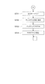
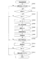
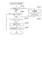
図6は、遊技制御部200による基本処理の動作を示すフローチャートである。
遊技制御部200は、パチンコ遊技機100の電源が投入されると、まず、RAM203(図3参照)へのアクセスを許可する(ステップ(以下、ステップを「S」と記載する)601)。そして、遊技制御部200は、RAM203をクリアするためのRAMクリアスイッチがONとなっているか否かを判断する(S602)。
RAMクリアスイッチがOFFである場合(S602でNo)、次に、遊技制御部200は、電源遮断時の動作に関するバックアップフラグがONとなっているか否かを判断する(S603)。
バックアップフラグがONである場合(S603でYes)、次に、遊技制御部200は、電源遮断時に作成されたチェックサムが正常か否かを判断する(S604)。
チェックサムが正常である場合(S604でYes)、次に、遊技制御部200は、復帰処理を実行する(S605)。この復帰処理において、遊技制御部200は、電源が遮断された状態からの復帰に伴う、演出制御部300等のサブ制御手段の設定を行う。具体的には、遊技制御部200は、電源が遮断される際におけるパチンコ遊技機100の遊技状態(大当たり遊技中か否か、高確率状態と低確率状態のいずれか、時短状態と時短無状態のいずれか)を反映させるように、サブ制御手段を設定するためのコマンドを演出制御部300へ出力する。また、この復帰処理において、遊技制御部200は、バックアップフラグをOFFにする。
FIG. 6 is a flowchart showing the basic processing performed by the game control unit 200.
When the power of the pachinko gaming machine 100 is turned on, the game control unit 200 first permits access to the RAM 203 (see FIG. 3) (step (hereinafter, “step” will be referred to as “S”) 601). Then, the game control unit 200 determines whether or not a RAM clear switch for clearing the RAM 203 is ON (S602).
When the RAM clear switch is OFF (No in S602), the game control unit 200 next determines whether or not the backup flag related to the operation at the time of power-off is ON (S603).
If the backup flag is ON (Yes in S603), the game control unit 200 next determines whether the checksum created when the power is turned off is normal (S604).
If the checksum is normal (Yes in S604), the game control unit 200 next executes a return process (S605). In this return process, the game control unit 200 performs setting of the sub-control means such as the effect control unit 300 accompanying the return from the state where the power is cut off. Specifically, the game control unit 200 determines the gaming state of the pachinko gaming machine 100 when the power is cut off (whether it is a big hit game, either a high probability state or a low probability state, a short time state and a short time state) The command for setting the sub-control means is output to the effect control unit 300 so that any one of them is reflected. In this return process, the game control unit 200 turns off the backup flag.

一方、RAMクリアスイッチがON(S602でYes)、バックアップフラグがOFF(S603でNo)、チェックサムが異常(S604でNo)のいずれかに該当する場合、次に遊技制御部200は、初期化処理として、RAM203の記憶内容をクリアし(S606)、RAM203の作業領域を設定する(S607)。そして、遊技制御部200は、サブ制御手段を設定(初期化)するためのコマンドを演出制御部300へ出力し、サブ基板(サブ制御手段)の設定を行う(S608)。サブ基板の設定には、各サブ基板に搭載されているRAM303、RAM313、RAM323をクリアすること等が含まれる。   On the other hand, if the RAM clear switch is ON (Yes in S602), the backup flag is OFF (No in S603), and the checksum is abnormal (No in S604), then the game control unit 200 is initialized. As processing, the stored contents of the RAM 203 are cleared (S606), and the work area of the RAM 203 is set (S607). Then, the game control unit 200 outputs a command for setting (initializing) the sub control means to the effect control unit 300, and sets the sub board (sub control means) (S608). The setting of the sub board includes clearing the RAM 303, RAM 313, and RAM 323 mounted on each sub board.

復帰処理(S605参照)が終了した後、またはサブ基板の設定(S608参照)が終了した後、遊技制御部200は、遊技制御に用いられる各種のカウンタおよびタイマーを設定する(S609)。そして、遊技制御部200は、割り込み許可(S610)、割り込み禁止(S611)、図柄乱数制御処理(S612)、初期値乱数更新処理(S613)、電源遮断フラグがONとなっているか否かの判断(S614)をループ処理として繰り返し実行する。
ここで、割り込み許可(S610)および割り込み禁止(S611)は、このループ処理(S610〜S614)の実行中に割り込み処理の実行を可能とするために設けられている。本実施の形態では、この割り込み処理により、遊技制御における主制御処理が実行される。主制御処理の詳細については後述する。
図柄乱数制御処理(S612)において、遊技制御部200は、特別図柄抽選で用いられる変動パターン乱数の更新を行う。
初期値乱数更新処理(S613)において、遊技制御部200は、遊技制御において用いられる各種の乱数値の初期値を更新する。
電源遮断フラグの判断において、電源遮断フラグがOFFである場合(S614でNo)、パチンコ遊技機100の電源は遮断されず、遊技制御部200は、ループ処理(S610〜S614)と共に割り込みによる主制御処理を繰り返し実行する。一方、電源遮断フラグがONである場合(S614でYes)、遊技制御部200は、パチンコ遊技機100の電源を遮断するための処理(電源遮断時処理)を開始する。
After the return process (see S605) is completed or after the setting of the sub-board (see S608) is completed, the game control unit 200 sets various counters and timers used for game control (S609). Then, the game control unit 200 determines whether or not the interrupt permission (S610), the interrupt prohibition (S611), the symbol random number control process (S612), the initial value random number update process (S613), and the power cutoff flag are ON. (S614) is repeatedly executed as a loop process.
Here, interrupt enable (S610) and interrupt disable (S611) are provided to enable execution of interrupt processing during execution of the loop processing (S610 to S614). In the present embodiment, main control processing in game control is executed by this interrupt processing. Details of the main control process will be described later.
In the symbol random number control process (S612), the game control unit 200 updates the variation pattern random number used in the special symbol lottery.
In the initial value random number update process (S613), the game control unit 200 updates initial values of various random values used in the game control.
In the determination of the power cut-off flag, if the power cut-off flag is OFF (No in S614), the power of the pachinko gaming machine 100 is not cut off, and the game control unit 200 performs main control by interruption together with the loop processing (S610 to S614). Repeat the process. On the other hand, when the power shut-off flag is ON (Yes in S614), the game control unit 200 starts a process for shutting off the power of the pachinko gaming machine 100 (power shut-off process).

図7は、遊技制御部200による電源遮断時処理の動作を示すフローチャートである。
電源遮断時処理において、遊技制御部200は、まず、各種の出力を行うための出力ポートの設定をクリアする(S701)。次に、遊技制御部200は、チェックサムを作成し、RAM203に格納する(S702)。次に、遊技制御部200は、バックアップフラグをONにし(S703)、RAM203へのアクセスを禁止して(S704)、無限ループに移行する。
FIG. 7 is a flowchart showing the operation of power-off processing performed by the game control unit 200.
In the power-off process, the game control unit 200 first clears the setting of the output port for performing various outputs (S701). Next, the game control unit 200 creates a checksum and stores it in the RAM 203 (S702). Next, the game control unit 200 turns on the backup flag (S703), prohibits access to the RAM 203 (S704), and shifts to an infinite loop.

〔遊技機の主制御処理〕
次に、パチンコ遊技機100の主制御処理を説明する。
遊技制御部200は、主制御処理において、パチンコ遊技機100における遊技を制御すると共に、サブ制御手段である演出制御部300に対して演出の制御を指示し、払出制御部330に対して賞球の払い出しの制御を指示する。
[Main control processing of gaming machines]
Next, main control processing of the pachinko gaming machine 100 will be described.
In the main control process, the game control unit 200 controls the game in the pachinko gaming machine 100, instructs the effect control unit 300, which is a sub-control means, to control the effect, and gives the payout control unit 330 a prize ball Instructs payout control.

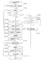
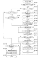
図8は、遊技制御部200の主制御処理を示すフローチャートである。
主制御処理は、遊技制御における一連の処理からなり、予め設定された一定時間(例えば4ミリ秒)ごとに繰り返し実行される。本実施の形態において、遊技制御部200は、予め設定された一定時間ごとに割り込みを発生させ、図6に示すループ処理の中で割り込みが許可(S610参照)されると、割り込み処理として主制御処理を実行する。図8に示すように、主制御処理では、乱数更新処理、スイッチ処理、図柄処理、電動役物処理、賞球処理、出力処理が順次実行される(S801〜S806)。
FIG. 8 is a flowchart showing main control processing of the game control unit 200.
The main control process includes a series of processes in game control, and is repeatedly executed every predetermined time (for example, 4 milliseconds). In the present embodiment, the game control unit 200 generates an interrupt every predetermined time set in advance, and when the interrupt is permitted in the loop process shown in FIG. 6 (see S610), the main control is performed as the interrupt process. Execute the process. As shown in FIG. 8, in the main control process, a random number update process, a switch process, a symbol process, an electric accessory process, a prize ball process, and an output process are sequentially executed (S801 to S806).

乱数更新処理(S801)では、遊技制御部200は、乱数制御部241の機能(サブルーチン)を呼び出し、遊技制御部200による遊技制御で用いられる各種の乱数の値を更新する。乱数の設定および乱数値の更新の詳細については後述する。   In the random number update process (S801), the game control unit 200 calls a function (subroutine) of the random number control unit 241, and updates various random number values used in the game control by the game control unit 200. Details of the setting of the random number and the update of the random value will be described later.

スイッチ処理(S802)としては、始動口スイッチ処理、ゲートスイッチ処理が行われる。
始動口スイッチ処理では、遊技制御部200は、乱数取得部231の機能(サブルーチン)を呼び出し、図3の第1始動口スイッチ211および第2始動口スイッチ212の状態を監視し、スイッチがONとなった場合に、特別図柄抽選のための処理を実行する。また、詳しくは後述するが、第1始動口スイッチ211および第2始動口スイッチ212において事前判定処理を行う場合は、特別図柄判定部234、変動パターン選択部235の各機能(サブルーチン)を呼び出し、事前判定のための処理を実行する。
ゲートスイッチ処理では、遊技制御部200は、乱数取得部231の機能(サブルーチン)を呼び出し、図3のゲートスイッチ214の状態を監視し、スイッチがONとなった場合に、普通図柄抽選のための処理を実行する。
これらのスイッチ処理の詳細な内容については後述する。
As the switch process (S802), a start port switch process and a gate switch process are performed.
In the start port switch process, the game control unit 200 calls the function (subroutine) of the random number acquisition unit 231, monitors the states of the first start port switch 211 and the second start port switch 212 in FIG. If this happens, a special symbol lottery process is executed. In addition, as will be described in detail later, when pre-determination processing is performed in the first start port switch 211 and the second start port switch 212, each function (subroutine) of the special symbol determination unit 234 and the variation pattern selection unit 235 is called, Execute processing for pre-determination.
In the gate switch process, the game control unit 200 calls the function (subroutine) of the random number acquisition unit 231 and monitors the state of the gate switch 214 in FIG. 3. Execute the process.
The detailed contents of these switch processes will be described later.

図柄処理(S803)としては、特別図柄処理、普通図柄処理が行われる。
特別図柄処理では、遊技制御部200は、特別図柄変動制御部233、特別図柄判定部234、変動パターン選択部235の各機能(サブルーチン)を呼び出し、特別図柄変動およびこの図柄変動に伴う処理を実行する。
普通図柄処理では、遊技制御部200は、普通図柄判定部232および普通図柄変動制御部236の機能(サブルーチン)を呼び出し、普通図柄変動およびこの図柄変動に伴う処理を実行する。
これらの図柄処理の詳細な内容については後述する。
As the symbol processing (S803), special symbol processing and normal symbol processing are performed.
In the special symbol process, the game control unit 200 calls the functions (subroutines) of the special symbol variation control unit 233, the special symbol determination unit 234, and the variation pattern selection unit 235, and executes the special symbol variation and the process associated with this symbol variation. To do.
In the normal symbol process, the game control unit 200 calls the functions (subroutines) of the normal symbol determination unit 232 and the normal symbol variation control unit 236, and executes the normal symbol variation and the process associated with this symbol variation.
The detailed contents of these symbol processes will be described later.

電動役物処理(S804)としては、大入賞口処理および電動チューリップ処理が行われる。
大入賞口処理では、遊技制御部200は、大入賞口動作制御部237の機能(サブルーチン)を呼び出し、所定の条件に基づいて特別電動役物である第1大入賞口125、第2大入賞口127および特別入賞口128の開放動作を制御する。
電動チューリップ処理では、遊技制御部200は、第2始動口扉動作制御部238の機能(サブルーチン)を呼び出し、所定の条件に基づいて普通電動役物である第2始動口扉61の開放動作を制御する。
これらの電動役物処理の詳細な内容については後述する。
As the electric accessory process (S804), a big prize opening process and an electric tulip process are performed.
In the special prize opening process, the game control unit 200 calls a function (subroutine) of the special prize opening operation control unit 237 and, based on predetermined conditions, the first big prize opening 125 and the second big prize winning which are special electric accessories. The opening operation of the mouth 127 and the special winning opening 128 is controlled.
In the electric tulip process, the game control unit 200 calls the function (subroutine) of the second start door operation control unit 238 and performs the opening operation of the second start door 61 that is a normal electric accessory based on a predetermined condition. Control.
Detailed contents of these electric accessory processing will be described later.

賞球処理(S805)では、遊技制御部200は、賞球処理部239の機能(サブルーチン)を呼び出し、入賞個数の管理および入賞に応じた賞球の払い出しの制御用コマンドをセットする。   In the prize ball processing (S805), the game control unit 200 calls a function (subroutine) of the prize ball processing unit 239, and sets a command for controlling the number of winning prizes and a control for paying out prize balls according to the winning prize.

出力処理(S806)では、遊技制御部200は、出力制御部240の機能(サブルーチン)を呼び出し、演出制御用のコマンドを演出制御部300へ出力し、払い出し制御用のコマンドを払出制御部330へ出力する。演出制御用コマンドは、S802からS804までの各処理において生成され、RAM203に設けられた制御用コマンドの格納領域に格納(セット)される。払い出し制御用コマンドは、S805の処理において生成され、RAM203に設けられた制御用コマンドの格納領域に格納(セット)される。RAM203には、制御用コマンドの種類ごとに格納領域が設定されている。   In the output process (S806), the game control unit 200 calls a function (subroutine) of the output control unit 240, outputs a command for effect control to the effect control unit 300, and sends a command for payout control to the payout control unit 330. Output. The effect control command is generated in each process from S802 to S804, and stored (set) in the control command storage area provided in the RAM 203. The payout control command is generated in the processing of S805 and stored (set) in the control command storage area provided in the RAM 203. A storage area is set in the RAM 203 for each type of control command.

出力制御部240は、RAM203の各制御用コマンドの格納領域を順に調べ、個々の格納領域に制御用コマンドが格納されていれば(すなわち、S802〜S805の処理で制御用コマンドが生成されていれば)、その制御用コマンドを読み出し、出力先(演出制御部300または払出制御部330)へ出力する。   The output control unit 240 sequentially checks the storage area of each control command in the RAM 203, and if the control command is stored in each storage area (that is, the control command is generated in the processing of S802 to S805). The control command is read out and output to the output destination (the effect control unit 300 or the payout control unit 330).

本実施の形態では、図8に示したように、一連の主制御処理の最後に出力処理を行う。すなわち、第2の処理手段としての上記各機能によるS802〜S805の各処理において生成されたコマンドを、その各処理においてはRAM203の対応する格納領域に格納しておく。そして、これらの処理の後に、第2の処理手段としての出力制御部240が、RAM203の格納領域に蓄積された、各処理で生成されたコマンドをまとめて出力する。言い換えれば、本実施の形態では、主制御処理を1サイクル実行すると、その1サイクルの実行において生成されたコマンドが、その1サイクルの実行における最後のコマンド生成が行われた後に、出力される。   In the present embodiment, as shown in FIG. 8, output processing is performed at the end of a series of main control processing. That is, the command generated in each process of S802 to S805 by the above functions as the second processing means is stored in the corresponding storage area of the RAM 203 in each process. After these processes, the output control unit 240 as a second processing unit collectively outputs the commands generated in each process accumulated in the storage area of the RAM 203. In other words, in this embodiment, when the main control process is executed for one cycle, the command generated in the execution of the one cycle is output after the last command generation in the execution of the one cycle is performed.

〔遊技機の基本動作の変形例〕
なお、図6乃至図8を参照して説明した動作例では、基本処理におけるループ処理の部分で割り込みを許可し、割り込み処理として一連の処理からなる主制御処理を実行した。しかしながら、主制御処理は、一定時間ごとに繰り返し実行されるように構成されていれば良く、具体的な実現手段(実行手順)は、図6乃至図8に示した例には限定されない。例えば、基本処理の一連の動作の中に主制御処理を組み入れておき、所定のタイミングで経過時間を計測し、一定時間(例えば4ミリ秒)ごとに主制御処理へ戻る構成としても良い。また、基本処理の一連の動作の中に主制御処理を組み入れる一方で、図6乃至図8を参照して説明した動作と同様に、一定時間ごとに割り込みを発生させ、割り込みが発生したならば基本処理中に組み入れられた主制御処理へ戻る構成としても良い。
[Modified example of basic operation of gaming machine]
In the operation example described with reference to FIGS. 6 to 8, the interrupt is permitted in the loop process portion of the basic process, and the main control process including a series of processes is executed as the interrupt process. However, the main control process only needs to be configured to be repeatedly executed at regular intervals, and the specific implementation means (execution procedure) is not limited to the examples illustrated in FIGS. For example, the main control process may be incorporated in a series of operations of the basic process, the elapsed time may be measured at a predetermined timing, and the process may return to the main control process every certain time (for example, 4 milliseconds). If the main control process is incorporated into the series of operations of the basic process, an interrupt is generated at regular intervals as in the operation described with reference to FIGS. It may be configured to return to the main control process incorporated in the basic process.

また、基本処理で生成されたコマンドを出力する場合は、原則として、コマンドを生成する度に、RAM203のコマンド格納領域に格納し、第2の処理手段である出力制御部240の機能を呼び出して出力する。基本処理は、遊技の進行に関わる主制御処理とは異なり、電源投入時にのみ行われる初期動作等の特別な処理である。また、基本処理は、電源投入時のパチンコ遊技機100の状態等の条件に基づく分岐により処理手順が変動する場合があるため、出力処理に漏れが無いように、生成したコマンドを速やかに出力する処理である。なお、関連する複数の処理により連続的にコマンドが生成される場合等、具体的な処理の要請に応じて、複数のコマンドをRAM203のコマンド格納領域に格納し、まとめて出力する処理手順を採っても良い。   When a command generated by basic processing is output, in principle, every time a command is generated, the command is stored in the command storage area of the RAM 203, and the function of the output control unit 240 as the second processing means is called. Output. Unlike the main control process related to the progress of the game, the basic process is a special process such as an initial operation performed only when the power is turned on. In addition, since the processing procedure may vary depending on the branching based on conditions such as the state of the pachinko gaming machine 100 when the power is turned on, the generated command is promptly output so that there is no omission in the output processing. It is processing. In addition, when a command is continuously generated by a plurality of related processes, a process procedure for storing a plurality of commands in the command storage area of the RAM 203 and outputting them in response to a specific process request is adopted. May be.

〔遊技制御部による乱数更新処理〕
特別図柄抽選等の遊技制御における各種の抽選に用いられる判定情報としての乱数値は、カウンタによって計数され、所定の初期値から始まって、図8に示す主制御処理の乱数更新処理(S801)が行われるたびに1ずつ加算される。そして、各抽選が行われた時点の値が始動口スイッチ処理(図9)およびゲートスイッチ処理(図10)で取得され、特別図柄処理(図11)や普通図柄処理(図16)で使用される。この乱数値のカウンタは無限ループカウンタであり、計数された乱数値が、設定されている乱数の最大値(例えば、後述する図20(a)に示した大当たり乱数では299)に達した後は、再び初期値に戻る。また、乱数更新処理は一定時間ごとに行われるため、各乱数の初期値が特定されてしまうと、更新間隔や初期値の情報に基づいて当選値が推定される恐れがある。そこで、主制御処理から図6に示す基本処理に戻った後、S613の初期値乱数更新処理において、各乱数の初期値をランダムに変更する。
[Random number update processing by game control unit]
A random number value as determination information used for various types of lotteries in game control such as special symbol lottery is counted by a counter, and a random number update process (S801) of the main control process shown in FIG. 8 starts from a predetermined initial value. Each time it is done, it is incremented by one. Then, the values at the time each lottery is performed are acquired by the start opening switch process (FIG. 9) and the gate switch process (FIG. 10), and used in the special symbol process (FIG. 11) and the normal symbol process (FIG. 16). The This random number counter is an infinite loop counter, and after the counted random number value reaches the set random number maximum value (for example, 299 for the jackpot random number shown in FIG. 20A described later) Return to the initial value again. In addition, since the random number update process is performed at regular intervals, if the initial value of each random number is specified, the winning value may be estimated based on the update interval and the initial value information. Therefore, after returning from the main control process to the basic process shown in FIG. 6, in the initial value random number update process of S613, the initial value of each random number is randomly changed.

〔遊技制御部による始動口スイッチ処理〕
図9は、図8のS802に示したスイッチ処理のうちの始動口スイッチ処理の内容を示すフローチャートである。
この始動口スイッチ処理は、第1始動口121における入賞に対する処理と、第2始動口122における入賞に対する処理とが順次行われる。図9を参照すると、遊技制御部200は、まず、第1始動口121に遊技球が入賞して第1始動口スイッチ211がONとなったか否かを判断する(S901)。第1始動口スイッチ211がONとなったならば、次に遊技制御部200は、第1始動口121の入賞における未変動分の保留数U1が上限値未満か否かを判断する(S902)。図9に示す例では、上限値を4個としている。保留数U1が上限値に達している場合は(S902でNo)、それ以上未変動分の入賞を保留することができないので、第1始動口121における入賞に対する処理を終了する。
[Start-up switch processing by game control unit]
FIG. 9 is a flowchart showing the contents of the start port switch process in the switch process shown in S802 of FIG.
In the start port switch process, a process for winning at the first start port 121 and a process for winning at the second start port 122 are sequentially performed. Referring to FIG. 9, the game control unit 200 first determines whether or not a game ball is won at the first start port 121 and the first start port switch 211 is turned on (S901). If the first start port switch 211 is turned on, the game control unit 200 next determines whether or not the unchanged hold number U1 in the winning of the first start port 121 is less than the upper limit value (S902). . In the example shown in FIG. 9, the upper limit value is four. If the number of holds U1 has reached the upper limit value (No in S902), it is not possible to hold any more unchanging winnings, so the process for winning at the first start port 121 is terminated.

一方、保留数U1が上限値未満である場合(S902でYes)、遊技制御部200の乱数取得部231は、今回の入賞による判定のための乱数値を取得し、RAM203に格納する(S903)。ここでは、第1始動口121の入賞なので、特別図柄抽選のための乱数値が取得される。このとき取得される乱数値は、S801の乱数更新処理で更新された値である。そして、この乱数値により、後の特別図柄処理において特別図柄抽選の結果が確定される。ここにいう乱数値としては、大当たり、小当たりまたははずれを決定する大当たり乱数値、大当たりの種類(大当たり遊技の終了後における時短状態か時短無状態、ロング開放パターン大当たりとショート開放パターン大当たりを決定する図柄乱数値(大当たり図柄乱数値)、図柄変動における変動パターンを特定するための変動パターン乱数値、はずれのときに後述のリーチ有り演出をするか否かを決定するリーチ乱数値、等が含まれる。   On the other hand, when the pending number U1 is less than the upper limit value (Yes in S902), the random number acquisition unit 231 of the game control unit 200 acquires a random value for determination by the current winning and stores it in the RAM 203 (S903). . Here, since the first starting port 121 is won, a random number value for special symbol lottery is acquired. The random value acquired at this time is a value updated by the random number update process of S801. Then, the result of the special symbol lottery is determined in the later special symbol processing by this random number value. The random value here is a jackpot random value that determines jackpot, jackpot or disappointment, jackpot type (short or short state after jackpot game, short or short time, long open pattern jackpot and short open pattern jackpot Design random number value (big hit symbol random number value), variation pattern random value for specifying variation pattern in symbol variation, reach random number value for determining whether or not to perform a reachable effect described later at the time of deviation, etc. .

次に、遊技制御部200は、事前判定処理を行う(S904)。事前判定処理とは、始動口における入賞により乱数の取得が既に行われているが後述する特別図柄処理によって乱数の判定が未だ行われていない入賞球(保留球)について、特別図柄処理によって乱数が判定されるよりも前にその乱数の判定を行う(事前判定)処理である。   Next, the game control unit 200 performs a prior determination process (S904). The pre-determination process means that a random number is obtained by a special symbol process for a winning ball (holding ball) for which a random number has already been acquired by a winning at the starting opening but a random symbol has not yet been determined by a special symbol process to be described later. This is a process of determining the random number before the determination (preliminary determination).

そして、本実施の形態の演出制御部300は、事前判定処理によって判定された乱数の判定結果(事前判定結果)に基づいて、特別図柄処理によって乱数が判定され、その判定結果が報知されるよりも前に、その判定結果を示唆する予告演出を行うことができる。この予告演出は、例えば、始動口における入賞により乱数の取得が既に行われているが特別図柄処理によって乱数の判定が未だ行われていない入賞球(保留球)の発生に応じて、画像表示部114に表示される保留表示演出(後述)等を用いて行われる。この事前判定に基づく予告演出により、予告演出に係る事前判定に対応する保留球に関して、その後に特別図柄処理による乱数の判定が行われた際の判定結果が遊技者に示唆される。これによって、遊技者は、保留球に対して期待を抱きながら遊技を行うことができる。事前判定に基づく予告演出の詳細については後述する。   And the production | generation control part 300 of this Embodiment determines a random number by the special symbol process based on the determination result (predetermined result) of the random number determined by the prior determination process, and notifies the determination result. Before that, it is possible to perform a notice effect that suggests the determination result. For example, in response to the occurrence of a winning ball (holding ball) for which random number acquisition has already been performed by winning a prize at the start opening but random number determination has not yet been performed by special symbol processing, the image display unit This is performed using a hold display effect (described later) displayed on 114. The notice effect based on this advance determination suggests to the player the determination result when the random number is determined by special symbol processing for the reserved ball corresponding to the advance determination related to the advance effect. Thereby, the player can play a game while expecting the reserved ball. Details of the notice effect based on the prior determination will be described later.

そして、遊技制御部200は、保留数U1の値を1加算する(S905)。
この後、遊技制御部200は、事前判定結果を演出制御部300に通知するために、S904の事前判定処理による事前判定情報を含む事前判定結果コマンドをRAM203にセットする(S906)。
さらに、遊技制御部200は、S905による保留数U1の増加を演出制御部300に通知するための保留数増加コマンドをRAM203にセットし(S907)、第1始動口121における入賞に対する処理を終了する。
Then, the game control unit 200 adds 1 to the value of the holding number U1 (S905).
Thereafter, the game control unit 200 sets a pre-determination result command including the pre-determination information by the pre-determination process in S904 in the RAM 203 in order to notify the effect control unit 300 of the pre-determination result (S906).
Furthermore, the game control unit 200 sets a hold number increase command for notifying the effect control unit 300 of an increase in the hold number U1 in S905 (S907), and ends the process for winning in the first start port 121. .

次に、第2始動口122における入賞に対する処理が行われる。図9を参照すると、次に遊技制御部200は、第2始動口122に遊技球が入賞して第2始動口スイッチ212がONとなったか否かを判断する(S908)。第2始動口スイッチ212がONとなったならば、次に、遊技制御部200は、第2始動口122の入賞における未変動分の保留数U2が上限値未満か否かを判断する(S909)。図9に示す例では、上限値を4個としている。保留数U2が上限値に達している場合は(S909でNo)、それ以上未変動分の入賞を保留することができないので、第2始動口122における入賞に対する処理を終了する。   Next, a process for winning in the second start port 122 is performed. Referring to FIG. 9, next, the game control unit 200 determines whether or not the game ball has won the second start port 122 and the second start port switch 212 is turned on (S908). If the second start port switch 212 is turned on, the game control unit 200 next determines whether or not the number of unreserved hold numbers U2 in the winning of the second start port 122 is less than the upper limit value (S909). ). In the example shown in FIG. 9, the upper limit value is four. If the number of holds U2 has reached the upper limit (No in S909), it is not possible to hold any more unchanging winnings, and the process for winning at the second start port 122 is terminated.

一方、保留数U2が上限値未満である場合(S909でYes)、遊技制御部200の乱数取得部231は、今回の入賞による抽選のための乱数値を取得し、RAM203に格納する(S910)。ここでは、第2始動口122の入賞なので、上記のS903と同様に、特別図柄抽選のための乱数値(大当たり乱数値、大当たり図柄乱数値)、リーチ乱数値、変動パターン乱数値など)が取得される。このとき取得される乱数値は、S801の乱数更新処理で更新された値である。そして、この乱数値により後の特別図柄処理において特別図柄抽選の結果が確定される。   On the other hand, if the pending number U2 is less than the upper limit value (Yes in S909), the random number acquisition unit 231 of the game control unit 200 acquires a random number value for the lottery by the current winning and stores it in the RAM 203 (S910). . Here, since the winning of the second starting port 122 is won, random numbers for special symbol lottery (big hit random number value, big hit symbol random number value, reach random number value, fluctuation pattern random number value, etc.) are acquired as in S903 above. Is done. The random value acquired at this time is a value updated by the random number update process of S801. Then, the result of the special symbol lottery is determined in the later special symbol processing by this random number value.

次に、遊技制御部200は、事前判定処理を行う(S911)。この事前判定処理の内容は、上記のS904と同様である。
そして、遊技制御部200は、保留数U2の値を1加算する(S912)。
この後、遊技制御部200は、事前判定結果を演出制御部300に通知するために、S911の事前判定処理による事前判定情報を含む事前判定結果コマンドをRAM203にセットする(S913)。
さらに、遊技制御部200は、S912による保留数U2の増加を演出制御部300に通知するための保留数増加コマンドをRAM203にセットし(S914)、第2始動口122における入賞に対する処理を終了する。
Next, the game control unit 200 performs a prior determination process (S911). The content of this pre-determination process is the same as that of said S904.
Then, the game control unit 200 adds 1 to the value of the holding number U2 (S912).
Thereafter, the game control unit 200 sets a pre-determination result command including pre-determination information obtained by the pre-determination process of S911 in the RAM 203 in order to notify the effect control unit 300 of the pre-determination result (S913).
Furthermore, the game control unit 200 sets a hold number increase command for notifying the effect control unit 300 of the increase in the hold number U2 in S912 in the RAM 203 (S914), and ends the process for winning at the second start port 122. .

〔遊技制御部によるゲートスイッチ処理〕
図10は、ゲート124を遊技球が通過した場合のゲートスイッチ処理の内容を示すフローチャートである。
このゲートスイッチ処理において、遊技制御部200は、まず、ゲート124を遊技球が通過してゲートスイッチ214がONとなったか否かを判断する(S1001)。ゲートスイッチ214がONとなったならば、次に遊技制御部200は、未変動分の保留数Gが上限値未満か否かを判断する(S1002)。図10に示す例では、上限値を4個としている。保留数Gが上限値に達している場合は(S1002でNo)、それ以上未変動分の入賞を保留することができないので、ゲートスイッチ処理を終了する。
[Gate switch processing by game control unit]
FIG. 10 is a flowchart showing the contents of the gate switch process when a game ball passes through the gate 124.
In this gate switch process, the game control unit 200 first determines whether or not the game ball has passed through the gate 124 and the gate switch 214 is turned on (S1001). If the gate switch 214 is turned on, the game control unit 200 next determines whether or not the unchanged holding number G is less than the upper limit value (S1002). In the example shown in FIG. 10, the upper limit value is four. If the number of reserves G has reached the upper limit (No in S1002), no more unchanging winnings can be reserved, and the gate switch processing is terminated.

一方、保留数Gが上限値未満である場合(S1002でYes)、遊技制御部200の乱数取得部231は、今回の入賞による抽選のための乱数値を取得し、RAM203に格納する(S1003)。ここでは、ゲート124の入賞なので、普通図柄抽選のための乱数値(当たり乱数値など)が取得される。   On the other hand, when the number G of holding is less than the upper limit value (Yes in S1002), the random number acquisition unit 231 of the game control unit 200 acquires a random value for the lottery by the current winning and stores it in the RAM 203 (S1003). . Here, since the gate 124 is won, a random number value (such as a winning random number value) for normal symbol lottery is acquired.

次に、遊技制御部200は、保留数Gの値を1加算する(S1004)。
S1004で保留数Gの値が加算された後、遊技制御部200は、S1004による保留数Gの増加を演出制御部300に通知するための保留数G増加コマンドをRAM203にセットし(S1005)、ゲート124における入賞に対する処理を終了する。
Next, the game control unit 200 adds 1 to the value of the holding number G (S1004).
After the value of the holding number G is added in S1004, the
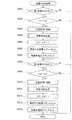
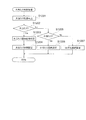
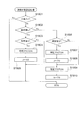
 game control unit 200 sets a holding number G increase command for notifying the effect control unit 300 of the increase in the holding number G in S1004 in the RAM 203 (S1005). The process for winning in the gate 124 is terminated.

〔遊技制御部による特別図柄処理〕
図11は、図8のS803に示した図柄処理のうちの特別図柄処理の内容を示すフローチャートである。
この特別図柄処理において、遊技制御部200の特別図柄変動制御部233は、まず、RAM203においてセットされるフラグの設定(以下、フラグ設定)において大当たり遊技フラグがONになっているか否かを調べる(S1101)。ここで、大当たり遊技フラグは、特別図柄抽選の結果が大当たりであることを識別するためにセットされるフラグである。大当たりの種類に応じて、ロング開放パターンフラグ、ショート開放パターンフラグの何れかがセットされる。なお、本実施の形態では、これらを総称して大当たり遊技フラグと呼ぶ。
[Special symbol processing by game control unit]
FIG. 11 is a flowchart showing the contents of the special symbol processing in the symbol processing shown in S803 of FIG.
In this special symbol process, the special symbol variation control unit 233 of the game control unit 200 first checks whether or not the jackpot game flag is ON in the setting of a flag set in the RAM 203 (hereinafter, flag setting) ( S1101). Here, the jackpot game flag is a flag that is set to identify that the result of the special symbol lottery is a jackpot. Either a long open pattern flag or a short open pattern flag is set according to the type of jackpot. In the present embodiment, these are collectively called a jackpot game flag.

大当たり遊技フラグがONである場合、既にパチンコ遊技機100は大当たり中であるので、特別図柄変動を開始することなく特別図柄処理を終了する(S1101でYes)。一方、大当たり遊技フラグがOFFである場合(S1101でNo)、次に特別図柄変動制御部233は、パチンコ遊技機100の現在の状態が特別図柄変動中か否かを判断する(S1102)。特別図柄変動中でない場合(S1102でNo)、次に特別図柄変動制御部233は、特別図柄の未変動分の保留数U1、U2(図9参照)に関する処理を行う(S1103〜S1106)。本実施の形態では、第1始動口121の入賞に係る保留数U1と第2始動口122の入賞に係る保留数U2とを区別しているので、この処理も対応する始動口ごとに個別に行う。   When the jackpot game flag is ON, the pachinko gaming machine 100 is already in the jackpot, so the special symbol processing is terminated without starting the special symbol variation (Yes in S1101). On the other hand, if the jackpot game flag is OFF (No in S1101), the special symbol variation control unit 233 next determines whether or not the current state of the pachinko gaming machine 100 is in the special symbol variation (S1102). If the special symbol is not changing (No in S1102), then the special symbol fluctuation control unit 233 performs processing related to the number U1 and U2 (see FIG. 9) of the special symbols that have not been changed (S1103 to S1106). In the present embodiment, the number of holds U1 related to winning of the first start port 121 and the number of holds U2 related to winning of the second start port 122 are distinguished, so this processing is also performed for each corresponding start port. .

具体的には、特別図柄変動制御部233は、まず第2始動口122の入賞に係る保留数U2が1以上か判断する(S1103)。保留数U2が1以上である場合(S1103でYes)、特別図柄変動制御部233は、保留数U2の値を1減算する(S1104)。一方、保留数U2=0である場合は(S1103でNo)、特別図柄変動制御部233は、次に第1始動口121の入賞に係る保留数U1が1以上か判断する(S1105)。保留数U1が1以上である場合(S1105でYes)、特別図柄変動制御部233は、保留数U1の値を1減算する(S1106)。一方、保留数U1=0である場合は(S1105でNo)、特別図柄の抽選を始動するための入賞が無いことを意味するため、特別図柄変動を開始せず、別ルーチンの客待ち設定処理を実行して処理を終了する(S1116)。
なお、本実施の形態では、第2始動口122の入賞に係る保留数U2に関する処理を優先させて行った。すなわち、保留数U2が1以上である場合は保留数U2に関する処理を行い、保留数U2=0である場合に保留数U1に関する処理を行っている(S803〜S806参照)。これに対し、第1始動口121と第2始動口122のどちらの入賞かに関わらず、入賞した順に保留数U1、U2を減算していくような制御とすることも可能である。
Specifically, the special symbol variation control unit 233 first determines whether or not the number of holds U2 related to winning in the second start port 122 is 1 or more (S1103). When the number of reservations U2 is 1 or more (Yes in S1103), the special symbol variation control unit 233 subtracts 1 from the value of the number of reservations U2 (S1104). On the other hand, if the hold number U2 = 0 (No in S1103), the special symbol variation control unit 233 next determines whether the hold number U1 related to winning in the first start port 121 is 1 or more (S1105). When the number of reservations U1 is 1 or more (Yes in S1105), the special symbol fluctuation control unit 233 subtracts 1 from the value of the number of reservations U1 (S1106). On the other hand, if the holding number U1 = 0 (No in S1105), it means that there is no winning for starting the special symbol lottery, so the special symbol change is not started, and the waiting process for waiting for customers set in another routine To finish the process (S1116).
In the present embodiment, priority is given to the processing related to the holding number U2 related to winning in the second start port 122. That is, when the number of holds U2 is 1 or more, the process related to the number of holds U2 is performed, and when the number of holds U2 = 0, the process related to the number of holds U1 is performed (see S803 to S806). On the other hand, regardless of whether the first start port 121 or the second start port 122 is won, it is also possible to perform control such that the hold numbers U1 and U2 are subtracted in the order of winning.

S1104またはS1106で保留数U1または保留数U2を減算した後、特別図柄変動制御部233は、RAM203のフラグ設定においてセットされた客待ちフラグをOFFとする(S1107)。客待ちフラグは、パチンコ遊技機100が客待ち状態であることを識別するためのフラグであり、客待ち設定処理(S1116、図15参照)においてセットされる。   After subtracting the holding number U1 or the holding number U2 in S1104 or S1106, the special symbol fluctuation control unit 233 turns off the customer waiting flag set in the flag setting of the RAM 203 (S1107). The customer waiting flag is a flag for identifying that the pachinko gaming machine 100 is in the customer waiting state, and is set in the customer waiting setting process (S1116, see FIG. 15).

次に、特別図柄変動制御部233は、別ルーチンによる大当たり判定処理および変動パターン選択処理を実行する(S1108、S1109)。詳しくは後述するが、この大当たり判定処理および変動パターン選択処理によって、第1特別図柄表示器221、第2特別図柄表示器222に変動表示される特別図柄の変動用の設定情報(大当たり図柄、遊技状態、変動パターン等)が決定される。なお、これらの情報は演出制御部300に送られる変動開始コマンドに含まれる。   Next, the special symbol variation control unit 233 executes jackpot determination processing and variation pattern selection processing by separate routines (S1108, S1109). Although details will be described later, the setting information for changing the special symbol displayed on the first special symbol display 221 and the second special symbol display 222 by the jackpot determination processing and the variation pattern selection processing (the jackpot symbol, game State, variation pattern, etc.) are determined. These pieces of information are included in a change start command sent to the effect control unit 300.

この後、特別図柄変動制御部233は、大当たり判定処理および変動パターン選択処理で決定された設定内容に基づき、図2に示す第1特別図柄表示器221、第2特別図柄表示器222により表示される特別図柄の変動を開始する(S1110)。そして、この設定内容を示す設定情報(大当たり図柄、遊技状態、変動パターン等)を含んだ変動開始コマンドを生成し、RAM203にセットする(S1111)。S1111でセットされた変動開始コマンドは、図8のS806に示した出力処理で演出制御部300へ送信される。   Thereafter, the special symbol variation control unit 233 is displayed by the first special symbol display unit 221 and the second special symbol display unit 222 shown in FIG. 2 based on the setting contents determined in the jackpot determination process and the variation pattern selection process. The special symbol change is started (S1110). Then, a change start command including setting information (a jackpot symbol, a gaming state, a change pattern, etc.) indicating the setting contents is generated and set in the RAM 203 (S1111). The variation start command set in S1111 is transmitted to the effect control unit 300 by the output process shown in S806 of FIG.

S1102で特別図柄変動中と判断された場合(S1102でYes)、またはS1111で変動開始コマンドがセットされた後、特別図柄変動制御部233は、変動時間を経過したか否かを判断する(S1112)。すなわち、S1110で特別図柄の変動を開始してからの経過時間がS1109の変動パターン選択処理で設定された変動時間に達したか否かが判断される。変動時間を経過していなければ(S1112でNo)、特別図柄変動が継続されるので、そのまま特別図柄処理が終了する。   When it is determined in S1102 that the special symbol is changing (Yes in S1102), or after the change start command is set in S1111, the special symbol fluctuation control unit 233 determines whether or not the fluctuation time has elapsed (S1112). ). That is, it is determined whether or not the elapsed time from the start of the variation of the special symbol in S1110 has reached the variation time set in the variation pattern selection process in S1109. If the variation time has not passed (No in S1112), the special symbol variation is continued, and the special symbol processing is terminated as it is.

一方、変動時間を経過した場合(S1112でYes)、特別図柄変動制御部233は、まず、第1特別図柄表示器221、第2特別図柄表示器222における特別図柄の変動をS1108の大当たり判定処理で決定された図柄で停止する(S1113)。後述する装飾図柄を停止させるための変動停止コマンドをRAM203にセットする(S1114)。そして、別ルーチンの停止中処理を実行する(S1115)。停止中処理の内容については後述する。S1114でセットされた変動停止コマンドは、図8のS806に示した出力処理で演出制御部300へ送信される。   On the other hand, when the variation time has elapsed (Yes in S1112), the special symbol variation control unit 233 first determines the variation of the special symbol in the first special symbol display 221 and the second special symbol display 222 as a big hit determination process in S1108. It stops at the symbol determined in (S1113). A change stop command for stopping a decorative design to be described later is set in the RAM 203 (S1114). Then, a stop routine process of another routine is executed (S1115). The contents of the stop process will be described later. The change stop command set in S1114 is transmitted to the effect control unit 300 by the output process shown in S806 of FIG.

〔遊技制御部による大当たり判定処理〕
図12は、大当たり判定処理(図11のS1108)の内容を示すフローチャートである。
この大当たり判定処理において、遊技制御部200の特別図柄判定部234は、まず、今回の特別図柄抽選における大当たり乱数値の判定を行い(S1201)、大当たりまたは小当たりしたか否かを判断する(S1202、S1205)。大当たりまたは小当たりしたか否かは、図9のS903またはS910で取得した大当たり乱数の値が、大当たりの当選値として設定された値または小当たりの当選値として設定された値と一致したか否かを判断することによって決定される(図20(a)参照)。
[Big hit judgment processing by game control unit]
FIG. 12 is a flowchart showing the contents of the jackpot determination process (S1108 in FIG. 11).
In this jackpot determination process, the special symbol determination unit 234 of the game control unit 200 first determines a jackpot random number value in the current special symbol lottery (S1201), and determines whether or not the jackpot or small hit is made (S1202). , S1205). Whether the jackpot or the jackpot is determined is whether the jackpot random number obtained in S903 or S910 in FIG. 9 matches the value set as the jackpot winning value or the value set as the jackpot winning value It is determined by judging whether (refer Fig.20 (a)).

S1201の乱数判定の結果が大当たりだった場合(S1202でYes)、次に特別図柄判定部234は、大当たり図柄乱数値の判定を行う(S1203)。この判定の結果に応じて、大当たりの種類(ロング開放パターン大当たりかショート開放パターン大当たり等)が決定される。何れの大当たりとなるかは、図9のS903またはS910で取得した大当たり図柄乱数の値が、大当たりの種類ごとに予め設定された値のうちの何れと一致したかによって決定される(図20(b)参照)。   If the result of the random number determination in S1201 is a big hit (Yes in S1202), then the special symbol determination unit 234 determines a big hit symbol random number value (S1203). Depending on the result of this determination, the type of jackpot (long open pattern jackpot or short open pattern jackpot etc.) is determined. Which jackpot is determined is determined by whether the value of the jackpot symbol random number acquired in S903 or S910 in FIG. 9 matches one of preset values for each jackpot type (FIG. 20 ( b)).

以上の判定の後、特別図柄判定部234は、大当たり図柄乱数の判定により決定された大当たりの種類を表す図柄(大当たり図柄)を設定情報としてRAM203にセットする(S1204)。   After the above determination, the special symbol determination unit 234 sets the symbol representing the jackpot type determined by the determination of the jackpot symbol random number (the jackpot symbol) in the RAM 203 as setting information (S1204).

S1201の乱数判定の結果が小当たりだった場合(S1202でNo、S1205でYes)、次に特別図柄判定部234は、小当たりであることを表す図柄(以下、小当たり図柄)を設定情報としてRAM203にセットする(S1206)。   If the result of the random number determination in S1201 is a small hit (No in S1202, Yes in S1205), then the special symbol determination unit 234 uses a symbol indicating that it is a small hit (hereinafter referred to as a small hit symbol) as setting information. It is set in the RAM 203 (S1206).

S1201の乱数判定の結果が大当たりでも小当たりでもない場合(S1202、S1205でNo)、次に特別図柄判定部234は、抽選にはずれたことを表す図柄(以下、はずれ図柄)を設定情報としてRAM203にセットする(S1207)。   If the result of the random number determination in S1201 is neither big win nor small win (No in S1202 and S1205), then the special symbol determination unit 234 uses the symbol indicating that the lottery is lost (hereinafter referred to as a lost symbol) as setting information in the RAM 203. (S1207).

〔遊技制御部による変動パターン選択処理〕
図13は、変動パターン選択処理(図11のS1109)の内容を示すフローチャートである。
この変動パターン選択処理において、遊技制御部200の変動パターン選択部235は、まず、パチンコ遊技機100の遊技状態(時短無状態か時短状態か、および高確率状態か低確率状態か)を参照する(S1301)。そして、大当たり判定処理(図12)のS1202の判断結果を用いて今回の特別図柄抽選で大当たりしたか否かを判断する(S1302)。そして、大当たりだった場合(S1302でYes)、変動パターン選択部235は、大当たり用の変動パターンテーブルをROM202から読み出してRAM203にセットする(S1303)。
[Change pattern selection process by game control unit]
FIG. 13 is a flowchart showing the contents of the variation pattern selection process (S1109 in FIG. 11).
In this variation pattern selection process, the variation pattern selection unit 235 of the game control unit 200 first refers to the gaming state of the pachinko gaming machine 100 (whether it is a short time state or a short time state, and a high probability state or a low probability state). (S1301). Then, using the determination result of S1202 of the jackpot determination process (FIG. 12), it is determined whether or not the jackpot was won in this special symbol lottery (S1302). If it is a big hit (Yes in S1302), the fluctuation pattern selecting unit 235 reads the big hit fluctuation pattern table from the ROM 202 and sets it in the RAM 203 (S1303).

一方、大当たりしなかった場合(S1302でNo)、次に変動パターン選択部235は、遊技者に大当たりを期待させるためのいわゆるリーチ演出を行うか否かを決定するための乱数値の判定を行う(S1304)。リーチ演出を行うか否かは、図9のS903またはS910で取得したリーチ乱数の値が予め設定された値と一致したか否かを判断することによって決定される(図20(c)参照)。
乱数値を用いた判定の結果、リーチ演出を行う場合(S1305でYes)、変動パターン選択部235は、リーチ用の変動パターンテーブルをROM202から読み出してRAM203にセットする(S1306)。また、リーチ演出を行わない場合(S1305でNo)、変動パターン選択部235は、はずれ用の変動パターンテーブルをROM202から読み出してRAM203にセットする(S1307)。
ここで、変動パターンテーブルとは、予め用意されている複数の変動パターン(変動時間3秒、7秒、13秒、15秒、30秒、60秒、90秒など)と変動パターン乱数の値とを対応付けたテーブルである。
On the other hand, if the jackpot is not hit (No in S1302), the variation pattern selection unit 235 then determines a random number value for determining whether or not to perform a so-called reach effect for causing the player to expect a jackpot. (S1304). Whether or not the reach effect is performed is determined by determining whether or not the reach random number value acquired in S903 or S910 in FIG. 9 matches a preset value (see FIG. 20C). .
As a result of the determination using the random number value, when the reach effect is performed (Yes in S1305), the variation pattern selection unit 235 reads the variation pattern table for reach from the ROM 202 and sets it in the RAM 203 (S1306). When the reach effect is not performed (No in S1305), the variation pattern selection unit 235 reads the variation pattern table for loss from the ROM 202 and sets it in the RAM 203 (S1307).
Here, the fluctuation pattern table includes a plurality of fluctuation patterns prepared in advance (fluctuation time 3 seconds, 7 seconds, 13 seconds, 15 seconds, 30 seconds, 60 seconds, 90 seconds, etc.) and values of fluctuation pattern random numbers. Is a table in which

次に、変動パターン選択部235は、図9のS903またはS910で取得した変動パターン乱数値およびS1303、S1306、S1307でセットされた変動パターンテーブルを用いて、変動パターン乱数値の判定を行う(S1308)。すなわち、変動パターン選択部235は、RAM203にセットされた変動パターンテーブルを参照し、変動パターン乱数の乱数値に応じた変動パターンを選択する。したがって、同じ乱数値が取得された場合でも、パチンコ遊技機100の遊技状態(時短状態か時短無し状態か、および高確率状態か低確率状態か)、特別図柄抽選の結果(大当たりしたか否か、大当たりしていない場合はリーチ演出を行うか否か)等の違いに応じて参照される変動パターンテーブルが異なるので、決定される変動パターンが異なる。   Next, the variation pattern selection unit 235 determines the variation pattern random value using the variation pattern random value acquired in S903 or S910 of FIG. 9 and the variation pattern table set in S1303, S1306, and S1307 (S1308). ). That is, the fluctuation pattern selection unit 235 refers to the fluctuation pattern table set in the RAM 203 and selects a fluctuation pattern corresponding to the random value of the fluctuation pattern random number. Therefore, even if the same random number value is acquired, the gaming state of the pachinko gaming machine 100 (whether it is a short-time state or no-short-time state, and a high-probability state or a low-probability state), the result of a special symbol lottery (whether or not it is a big hit The variation pattern table to be referred to differs depending on the difference in whether or not the reach effect is performed when the jackpot is not hit.

この後、変動パターン選択部235は、S1308で選択した変動パターンを設定情報としてRAM203にセットする(S1309)。S1309でセットされた変動パターンの設定情報は、図11のS1111でセットされる変動開始コマンドに含まれ、図8のS806に示した出力処理で演出制御部300へ送信される。本実施の形態で選択される変動パターンおよびその設定の詳細については後述する。   Thereafter, the variation pattern selection unit 235 sets the variation pattern selected in S1308 as setting information in the RAM 203 (S1309). The variation pattern setting information set in S1309 is included in the variation start command set in S1111 of FIG. 11, and is transmitted to the effect control unit 300 by the output process shown in S806 of FIG. Details of the variation pattern selected in this embodiment and its setting will be described later.

〔遊技制御部による停止中処理〕
図14は、停止中処理(図11のS1115)の内容を示すフローチャートである。
この停止中処理において、遊技制御部200は、まず、RAM203のフラグ設定において時短状態であることを示すフラグ(以下、時短フラグ)がONになっているか否かを調べる(S1401)。時短フラグがONである場合(S1401でYes)、遊技制御部200は、時短状態での抽選回数(変動回数)Jの値を1減算し(S1402)、抽選回数Jが0になったか否かを調べる(S1403)。そして、抽選回数J=0であれば(S1403でYes)、時短フラグをOFFにする(S1404)。なお、時短フラグをONにする操作と、抽選回数Jの初期値の設定は、後述の大入賞口処理(図17)における遊技状態設定処理(図18)で行われる。
[Processing during stop by game control unit]
FIG. 14 is a flowchart showing the contents of the suspension process (S1115 in FIG. 11).
In this stop process, the game control unit 200 first checks whether or not a flag indicating that the time is short (hereinafter, a time short flag) is turned on in the flag setting of the RAM 203 (S1401). When the time reduction flag is ON (Yes in S1401), the game control unit 200 subtracts 1 from the value of the number of lotteries (number of fluctuations) J in the time reduction state (S1402), and whether or not the number of lotteries J has become zero. (S1403). If the number of lotteries J = 0 (Yes in S1403), the time reduction flag is turned OFF (S1404). It should be noted that the operation for turning on the hourly flag and the setting of the initial value of the lottery count J are performed in a game state setting process (FIG. 18) in a special winning opening process (FIG. 17) described later.

時短フラグがOFFであった場合(S1401でNo)またはS1404で時短フラグをOFFにした後、あるいはS1402で減算した後の抽選回数Jの値が0でない場合(S1403でNo)、次に遊技制御部200は、RAM203のフラグ設定において高確率状態であることを示すフラグ(以下、確変フラグ)がONになっているか否かを調べる(S1405)。なお、この確変フラグと先の時短フラグが共にONである場合は、高確率時短遊技状態であり、確変フラグがONであり時短フラグがOFFである場合は、高確率時短無遊技状態である。   If the time reduction flag is OFF (No in S1401), or after the time reduction flag is turned OFF in S1404, or if the value of the lottery count J after subtraction in S1402 is not 0 (No in S1403), then game control The unit 200 checks whether or not a flag indicating a high probability state (hereinafter, probability variation flag) is set to ON in the flag setting of the RAM 203 (S1405). When both the probability variation flag and the previous time-short flag are ON, the high-probability short-time gaming state is established, and when the probability variation flag is ON and the time-short flag is OFF, the high-probability time-short no-game state.

確変フラグがONである場合(S1405でYes)、遊技制御部200は、高確率状態での抽選回数(変動回数)Xの値を1減算し(S1406)、抽選回数Xが0になったか否かを調べる(S1407)。そして、抽選回数X=0であれば(S1407でYes)、確変フラグをOFFにする(S1408)。なお、確変フラグをONにする操作と、抽選回数Xの初期値の設定は、後述の大入賞口処理(図17)における遊技状態設定処理(図18)で行われる。   When the probability variation flag is ON (Yes in S1405), the game control unit 200 subtracts 1 from the value of the number of lotteries (number of variations) X in the high probability state (S1406), and whether or not the number of lotteries X has become 0. This is checked (S1407). If the number of lotteries X = 0 (Yes in S1407), the probability variation flag is turned OFF (S1408). Note that the operation for turning on the probability change flag and the setting of the initial value of the lottery number X are performed in a game state setting process (FIG. 18) in a special prize opening process (FIG. 17) described later.

確変フラグがOFFであった場合(S1405でNo)またはS1408で確変フラグをOFFにした後、あるいはS1406で減算した後の抽選回数Xの値が0でない場合(S1407でNo)、次に遊技制御部200は、今回の特別図柄抽選で大当たりしたか否かを判断する(S1409)。そして、大当たりだった場合(S1409でYes)、次に遊技制御部200は、大当たりの種類がロング開放パターン大当たりか否かを判断する(S1410)。   If the probability change flag is OFF (No in S1405), or after the probability change flag is turned OFF in S1408, or if the value of the number of lotteries X after subtraction in S1406 is not 0 (No in S1407), then game control The unit 200 determines whether or not a big win has been won in this special symbol lottery (S1409). If it is a big hit (Yes in S1409), the game control unit 200 next determines whether or not the type of the big win is a long open pattern big hit (S1410).

ここで、大当たりか否かの判断は、大当たり判定処理(図12)の判定結果に基づいて判断することができる。例えば、後述する図20(b)の図表に示す図柄の何れかがセットされているならば、S1409でYesである。大当たり判定処理によりRAM203に、はずれ図柄または小当たり図柄がセットされているならば、S1409でNoである。   Here, the determination of whether or not the jackpot is possible can be made based on the determination result of the jackpot determination process (FIG. 12). For example, if any of the symbols shown in the diagram of FIG. 20B to be described later is set, Yes is obtained in S1409. If a lost symbol or a small bonus symbol is set in the RAM 203 by the big hit determination process, No in S1409.

大当たりの種類がロング開放パターン大当たりであった場合(S1410でYes)、遊技制御部200は、ロング開放パターンフラグをONにする(S1411)。これにより、RAM203の遊技状態の設定が、大当たりの種類がロング開放パターン大当たりである大当たり遊技状態(ロング開放パターン大当たり遊技状態)となる。   If the jackpot type is a long open pattern jackpot (Yes in S1410), the game control unit 200 turns on the long open pattern flag (S1411). Thereby, the setting of the gaming state in the RAM 203 becomes a jackpot gaming state (long opening pattern jackpot gaming state) in which the jackpot type is the long opening pattern jackpot.

大当たりの種類がショート開放パターン大当たりでなかった場合(S1410でNo)、遊技制御部200は、ショート開放パターンフラグをONにする(S1412)。これにより、RAM203の遊技状態の設定が、大当たりの種類がショート開放パターン大当たりである大当たり遊技状態(ショート開放パターン大当たり遊技状態)となる。   If the type of jackpot is not a short-open pattern jackpot (No in S1410), the game control unit 200 turns on the short-open pattern flag (S1412). Thereby, the setting of the gaming state in the RAM 203 becomes a jackpot gaming state (short opening pattern jackpot gaming state) in which the type of jackpot is a short opening pattern jackpot.

S1411またはS1412で大当たり遊技フラグをONにした後、遊技制御部200は、抽選回数J、Xの値を初期化する(S1413)。また、遊技制御部200は、S1401において時短フラグがONであって、S1403において抽選回数Jが0でなかった場合に、時短フラグをOFFにする(S1414)。同様に、S1405において確変フラグがONであって、S1407において抽選回数Xが0でなかった場合に、確変フラグをOFFにする(S1414)。   After turning on the jackpot game flag in S1411 or S1412, the game control unit 200 initializes the values of the lottery times J and X (S1413). Further, the game control unit 200 turns off the time reduction flag when the time reduction flag is ON in S1401 and the lottery count J is not 0 in S1403 (S1414). Similarly, when the probability variation flag is ON in S1405 and the number of lotteries X is not 0 in S1407, the probability variation flag is turned OFF (S1414).

S1413で抽選回数J、Xの値を初期化した後、遊技制御部200は、オープニング動作を開始する(S1417)。ここで、オープニング動作の内容は、S1411、S1412の何れで当たり遊技フラグがONとなったかに応じて異なる。すなわち、大当たり遊技フラグの状態に応じて、ロング開放パターン大当たり遊技、ショート開放パターン大当たり遊技の各遊技状態において設定されたオープニング動作の何れかが行われることとなる。
この後、遊技制御部200は、演出制御部300において大当たり遊技フラグに応じたオープニング動作における演出を行うためのオープニングコマンドをRAM203にセットして(S1418)、停止中処理を終了する。このオープニングコマンドは、図8のS806に示した出力処理で演出制御部300へ送信される。
After initializing the values of the lottery times J and X in S1413, the game control unit 200 starts an opening operation (S1417). Here, the content of the opening operation differs depending on whether the winning game flag is turned ON in S1411 or S1412. That is, depending on the state of the jackpot game flag, one of the opening operations set in each game state of the long open pattern jackpot game and the short release pattern jackpot game is performed.
Thereafter, the game control unit 200 sets an opening command for performing an effect in the opening operation according to the jackpot game flag in the effect control unit 300 in the RAM 203 (S1418), and ends the in-stop process. This opening command is transmitted to the effect control unit 300 in the output process shown in S806 of FIG.

これに対し、今回の特別図柄抽選の結果が大当たりでなかった場合(S1409でNo)、次に遊技制御部200は、今回の特別図柄抽選の結果が小当たりであったか否かを判断する(S1415)。小当たりでなかった場合は(S1415でNo)、停止中処理を終了する。
一方、小当たりであった場合(S1415でYes)、遊技制御部200は、小当たり遊技を開始する(S1416)。これにより、RAM203の遊技状態の設定が小当たり遊技状態となる。なお、小当たり遊技では、前述したように、第1大入賞口125を所定回数開閉し、所定時間経過後に終了する。
On the other hand, when the result of the special symbol lottery this time is not a big hit (No in S1409), the game control unit 200 determines whether or not the result of the special symbol lottery this time is a big hit (S1415). ). If it is not a small hit (No in S1415), the in-stop process is terminated.
On the other hand, when it is a small hit (Yes in S1415), the game control unit 200 starts a small hit game (S1416). Thereby, the setting of the gaming state in the RAM 203 becomes the small hit gaming state. In the small hit game, as described above, the first big prize opening 125 is opened and closed a predetermined number of times, and is ended after a predetermined time has elapsed.

〔遊技制御部による客待ち設定処理〕
図15は、客待ち設定処理(図11のS1116)の内容を示すフローチャートである。
この客待ち設定処理において、遊技制御部200は、まず、RAM203のフラグ設定において客待ちフラグがONになっているか否かを調べる(S1501)。ここで、客待ちフラグは、パチンコ遊技機100が客待ち状態であることを識別するためにセットされるフラグである。
[Customer waiting setting process by game control unit]
FIG. 15 is a flowchart showing the contents of the customer waiting setting process (S1116 in FIG. 11).
In this customer waiting setting process, the game control unit 200 first checks whether or not the customer waiting flag is ON in the flag setting of the RAM 203 (S1501). Here, the customer waiting flag is a flag that is set to identify that the pachinko gaming machine 100 is in a customer waiting state.

客待ちフラグがONである場合、パチンコ遊技機100は客待ち状態であるので、そのまま処理を終了する(S1501でYes)。一方、客待ちフラグがOFFである場合、遊技制御部200は、客待ちコマンドを生成してRAM203にセットし(S1502)、客待ちフラグをONにする(S1503)。S1502でセットされた客待ちコマンドは、図8のS806に示した出力処理で演出制御部300へ送信される。なお、客待ちフラグとは、特別図柄の変動が停止して、保留が無い状態でセットされるものである。   If the customer waiting flag is ON, the pachinko gaming machine 100 is in a customer waiting state, and thus the processing is terminated as it is (Yes in S1501). On the other hand, when the customer waiting flag is OFF, the game control unit 200 generates a customer waiting command and sets it in the RAM 203 (S1502), and turns on the customer waiting flag (S1503). The customer waiting command set in S1502 is transmitted to the effect control unit 300 in the output process shown in S806 of FIG. The customer waiting flag is set in a state where there is no suspension with the special symbol change stopped.

〔遊技制御部による普通図柄処理〕
図16は、図8のS803に示した図柄処理のうちの普通図柄処理の内容を示すフローチャートである。
この普通図柄処理において、遊技制御部200の普通図柄変動制御部236は、まず、RAM203のフラグ設定において補助遊技フラグがONになっているか否かを調べる(S1601)。ここで、補助遊技フラグは、普通図柄抽選で当選した場合にセットされるフラグである。補助遊技フラグが設定されている状態は、第2始動口扉61が後述の電動チューリップ処理(図19)にしたがって開放され、第2始動口122に入賞し易い状態である(補助遊技状態)。
[Normal symbol processing by game control unit]
FIG. 16 is a flowchart showing the contents of the normal symbol processing in the symbol processing shown in S803 of FIG.
In this normal symbol process, the normal symbol variation control unit 236 of the game control unit 200 first checks whether or not the auxiliary game flag is ON in the flag setting of the RAM 203 (S1601). Here, the auxiliary game flag is a flag that is set when a normal symbol lottery is won. The state in which the auxiliary game flag is set is a state in which the second start port 61 is opened in accordance with an electric tulip process (FIG. 19) described later and the second start port 122 is easily won (auxiliary game state).

補助遊技フラグがONである場合、既に補助遊技状態となっており、普通図柄が停止している状態なので、普通図柄変動を開始することなく普通図柄処理を終了する(S1601でYes)。一方、補助遊技フラグがOFFである場合(S1601でNo)、次に普通図柄変動制御部236は、パチンコ遊技機100の現在の状態が普通図柄変動中か否かを判断する(S1602)。普通図柄変動中でない場合(S1602でNo)、次に普通図柄変動制御部236は、普通図柄の未変動分の保留数G(図10参照)が1以上か判断する(S1603)。保留数G=0である場合は(S1603でNo)、普通図柄の抽選を始動するための入賞が無いことを意味するため、普通図柄変動を開始せずに処理を終了する。   When the auxiliary game flag is ON, since the auxiliary game state has already been reached and the normal symbol is stopped, the normal symbol process is terminated without starting the normal symbol variation (Yes in S1601). On the other hand, if the auxiliary game flag is OFF (No in S1601), then the normal symbol variation control unit 236 determines whether or not the current state of the pachinko gaming machine 100 is in the normal symbol variation (S1602). If the normal symbol is not changing (No in S1602), then the normal symbol variation control unit 236 determines whether the number G of the normal symbols remaining unchanged (see FIG. 10) is 1 or more (S1603). If the holding number G = 0 (No in S1603), it means that there is no winning for starting the normal symbol lottery, and therefore the processing is terminated without starting the normal symbol variation.

これに対し、保留数Gが1以上である場合(S1603でYes)、普通図柄変動制御部236は、保留数Gの値を1減算する(S1604)。そして、普通図柄判定部232が、今回の普通図柄抽選における当たり乱数の判定を行って、普通図柄抽選に当選したか否かを判断する(S1605)。当選したか否かは、図10のS1003で取得した当たり乱数の値が、後述する図20(d)に示すテーブル等において当選値として設定された値と一致したか否かを判断することによって決定される。   On the other hand, when the reserved number G is 1 or more (Yes in S1603), the normal symbol variation control unit 236 subtracts 1 from the value of the reserved number G (S1604). Then, the normal symbol determination unit 232 determines a winning random number in the current normal symbol lottery to determine whether or not the normal symbol lottery has been won (S1605). Whether or not the winner has been won is determined by determining whether or not the value of the winning random number acquired in S1003 in FIG. 10 matches the value set as the winning value in the table shown in FIG. It is determined.

次に、普通図柄変動制御部236は、普通図柄抽選の結果に応じて普通図柄の設定を行う(S1606)。すなわち、普通図柄抽選に当選した場合は、当選したことを表す図柄(以下、当たり図柄)を設定情報としてRAM203にセットする。一方、普通図柄抽選に当選しなかった場合は、抽選にはずれたことを表す図柄(以下、はずれ図柄)を設定情報としてRAM203にセットする。   Next, the normal symbol fluctuation control unit 236 sets the normal symbol according to the result of the normal symbol lottery (S1606). That is, when a normal symbol lottery is won, a symbol representing the winning (hereinafter referred to as a winning symbol) is set in the RAM 203 as setting information. On the other hand, when the normal symbol lottery is not won, a symbol indicating that the lottery has been lost (hereinafter referred to as a lost symbol) is set in the RAM 203 as setting information.

次に、普通図柄変動制御部236は、普通図柄の変動時間の設定を行う(S1607)。この変動時間は、図14におけるS1404、S1414、後述の図18におけるS1804、S1807等の処理で設定される時短フラグに基づいて設定される。すなわち、S1607による設定の際に時短フラグがONである場合は、短時間(例えば1.5秒)に設定され、時短フラグがOFFである場合は、長時間(例えば4.0秒)に設定される。この設定の後、普通図柄変動制御部236は、S1607の設定内容に基づき、図2(a)および図3に示す普通図柄表示器223における普通図柄の変動を開始する(S1608)。なお、普通図柄の変動パターンを抽選により決定することもできる。この場合、例えば、遊技球がゲート124を通過した際に、乱数取得部231が普通図柄の変動パターン乱数値を取得し、S1607において、普通図柄変動制御部236が普通図柄の変動パターン乱数値を判定することにより、変動時間が設定される。   Next, the normal symbol variation control unit 236 sets the variation time of the normal symbol (S1607). This variation time is set based on the time reduction flag set in the processes of S1404 and S1414 in FIG. 14, and S1804 and S1807 in FIG. That is, when the time reduction flag is ON in the setting in S1607, it is set to a short time (for example, 1.5 seconds), and when the time reduction flag is OFF, it is set to a long time (for example, 4.0 seconds). Is done. After this setting, the normal symbol fluctuation control unit 236 starts normal symbol fluctuations in the normal symbol display 223 shown in FIGS. 2A and 3 based on the setting contents of S1607 (S1608). In addition, the fluctuation pattern of a normal symbol can also be determined by lottery. In this case, for example, when the game ball passes through the gate 124, the random number acquisition unit 231 acquires the normal pattern variation pattern random value, and in S1607, the normal symbol variation control unit 236 generates the normal symbol variation pattern random value. By determining, the variation time is set.

S1608で普通図柄の変動を開始した後、またはS1602で普通図柄変動中と判断された場合(S1602でYes)、普通図柄変動制御部236は、変動時間を経過したか否かを判断する(S1609)。すなわち、S1608で普通図柄の変動を開始してからの経過時間がS1607で設定された変動時間に達したか否かが判断される。変動時間を経過していなければ(S1609でNo)、普通図柄変動が継続されるので、そのまま普通図柄処理が終了する。   After starting the change of the normal symbol in S1608 or when it is determined that the normal symbol is changing in S1602 (Yes in S1602), the normal symbol change control unit 236 determines whether or not the change time has passed (S1609). ). That is, it is determined whether or not the elapsed time from the start of fluctuation of the normal symbol in S1608 has reached the fluctuation time set in S1607. If the variation time has not passed (No in S1609), the normal symbol variation is continued, and the normal symbol processing is terminated as it is.

一方、変動時間が終了した場合(S1609でYes)、普通図柄変動制御部236は、普通図柄表示器223における普通図柄の変動を停止する(S1610)。そして、普通図柄変動制御部236は、S1605の判定結果が当選であったか否かを判断する(S1611)。当選であったならば(S1611でYes)、補助遊技フラグをONにする(S1612)。一方、抽選にはずれたならば(S1611でNo)、補助遊技フラグをONにすること無く普通図柄処理を終了する。   On the other hand, when the fluctuation time is over (Yes in S1609), the normal symbol fluctuation control unit 236 stops the fluctuation of the normal symbol in the normal symbol display 223 (S1610). Then, the normal symbol variation control unit 236 determines whether or not the determination result in S1605 is a win (S1611). If it is a win (Yes in S1611), the auxiliary game flag is turned ON (S1612). On the other hand, if the lottery is off (No in S1611), the normal symbol processing is terminated without turning on the auxiliary game flag.

〔遊技制御部による大入賞口処理〕
図17は、図8のS804に示した電動役物処理のうちの大入賞口処理の内容を示すフローチャートである。
この大入賞口処理において、遊技制御部200の大入賞口動作制御部237は、まず、RAM203のフラグ設定において大当たり遊技フラグがONになっているか否かを調べる(S1701)。大当たり遊技フラグがOFFである場合、第2大入賞口127への入賞はないので、大入賞口処理を終了する(S1701でNo)。一方、大当たり遊技フラグがONである場合(S1701でYes)、次に大入賞口動作制御部237は、パチンコ遊技機100が停止中処理(図14)で開始された大当たり時の動作制御におけるオープニング動作の最中か否かを判断する(S1702)。
[Large winning mouth processing by game control unit]
FIG. 17 is a flowchart showing the contents of the special prize opening process in the electric accessory process shown in S804 of FIG.
In this big prize opening process, the big prize opening operation control unit 237 of the game control unit 200 first checks whether or not the big hit game flag is ON in the flag setting of the RAM 203 (S1701). When the big hit game flag is OFF, there is no winning in the second big winning opening 127, so the big winning opening process is terminated (No in S1701). On the other hand, when the jackpot game flag is ON (Yes in S1701), the big prize opening operation control unit 237 opens in the operation control at the time of jackpot that is started in the pachinko gaming machine 100 being stopped (FIG. 14) It is determined whether or not the operation is in progress (S1702).

パチンコ遊技機100がオープニング中である場合(S1702でYes)、次に大入賞口動作制御部237は、予め設定されたオープニング動作が行われるべき時間(オープニング時間)を経過したか否かを判断する(S1703)。オープニング時間を経過していないならば、第2大入賞口127でのオープニング動作が継続されるので、大入賞口処理を終了する(S1703でNo)。一方、オープニング時間を経過したならば(S1703でYes)、次に大入賞口動作制御部237は、第2大入賞口127の作動設定を行い(S1704)、入賞個数Cを初期化(C=0)し(S1705)、第2大入賞口127の作動のラウンド数Rの値を現在の値から1加算して(S1706)、第2大入賞口127を作動開始(開放)する(S1707)。   If the pachinko gaming machine 100 is opening (Yes in S1702), the next prize opening operation control unit 237 determines whether or not a predetermined time (opening time) for performing the opening operation has elapsed. (S1703). If the opening time has not elapsed, the opening operation at the second big prize opening 127 is continued, and the big prize opening process is terminated (No in S1703). On the other hand, if the opening time has elapsed (Yes in S1703), the special winning opening operation control unit 237 next sets the operation of the second special winning opening 127 (S1704) and initializes the winning number C (C = 0) (S1705), the value of the round number R of the operation of the second big prize opening 127 is incremented by 1 from the current value (S1706), and the second big prize opening 127 is started (opened) (S1707). .

S1704の作動設定では、第2大入賞口127の作動パターンと、その作動パターンで作動させるラウンド数(作動ラウンド数)とが設定される。第2大入賞口127が作動する場合としては、特別図柄抽選で、ロング開放パターン大当たりであった場合またはショート開放パターン大当たりであった場合とがある。作動パターンおよびラウンド数は、これらの当たりの種類に応じて様々に設定される。なお、大当たり遊技においては、第2大入賞口127の作動を複数回(複数ラウンド)連続して行うことが規定されている。   In the operation setting of S1704, the operation pattern of the second big prize opening 127 and the number of rounds (operation round number) operated by the operation pattern are set. The case where the second big prize opening 127 is operated may be a case where a long open pattern jackpot or a short open pattern jackpot is made in a special symbol lottery. The operation pattern and the number of rounds are variously set according to the hit type. In the jackpot game, it is stipulated that the operation of the second big prize opening 127 is continuously performed a plurality of times (a plurality of rounds).

次に、大入賞口動作制御部237は、S1704で設定された作動パターンにおける開放時間を経過したか否かを判断する(S1708)。第2大入賞口127での開放状態が開放時間を経過していない場合(S1708でNo)、次に大入賞口動作制御部237は、第2大入賞口127への入賞個数Cが規定の個数(例えば6個)以上か否かを判断する(S1709)。開放時間を経過しておらず、かつ入賞個数Cが規定個数未満である場合は、第2大入賞口127の作動状態(開放状態)が継続されるので、大入賞口処理を終了する(S1709でNo)。一方、開放時間を経過したか(S1708でYes)、または入賞個数Cが規定個数に達した場合(S1709でYes)、大入賞口動作制御部237は、第2大入賞口127を作動終了(閉口)する(S1710)。   Next, the special winning opening operation control unit 237 determines whether or not the opening time in the operation pattern set in S1704 has elapsed (S1708). If the open state at the second big prize opening 127 has not passed the opening time (No in S1708), then the big prize opening operation control unit 237 defines the number C of winning prizes to the second big prize opening 127. It is determined whether or not the number is more than 6 (for example, 6) (S1709). If the opening time has not elapsed and the number C of winning prizes is less than the specified number, the operating state (opening state) of the second big winning opening 127 is continued, so that the big winning opening process is terminated (S1709). No). On the other hand, if the opening time has passed (Yes in S1708) or the winning number C has reached the specified number (Yes in S1709), the special winning opening operation control unit 237 ends the operation of the second large winning opening 127 ( (S1710).

次に、本実施の形態のパチンコ遊技機100では、ラウンドに応じて、特別入賞口128を開状態にすることが予め定められている。そこで、現在のラウンドが、特別入賞口開放ラウンドであるか否かを判断する(S1711)。
そして、特別入賞口開放ラウンドである場合には(S1711でYes)、特別入賞口処理を実行する(S1712)。
S1712の特別入賞口処理では、所定のタイミングにて所定の開放時間だけ特別入賞口128を開状態にする。そして、特別入賞口128に遊技球が入球した場合には、大当たり遊技の終了後の遊技状態が高確率時短遊技状態になる「高確率時短移行確定フラグ」をRAM203にセットする。一方、特別入賞口128が作動した後に、特別入賞口128に遊技球が入球しなければ、大当たり終了後の遊技状態が低確率時短遊技状態になる「低確率時短移行確定フラグ」をRAM203にセットする。
Next, in the pachinko gaming machine 100 according to the present embodiment, it is predetermined that the special winning opening 128 is opened in accordance with the round. Therefore, it is determined whether or not the current round is a special winning opening opening round (S1711).
If it is the special winning opening opening round (Yes in S1711), the special winning opening process is executed (S1712).
In the special prize opening process of S1712, the special prize opening 128 is opened for a predetermined opening time at a predetermined timing. When a game ball enters the special winning opening 128, a “high probability short transition determination flag” is set in the RAM 203 so that the gaming state after the end of the big hit game becomes a high probability short gaming state. On the other hand, after the special winning opening 128 is activated, if a game ball does not enter the special winning opening 128, a “low probability short transition confirmation flag” is set in the RAM 203 so that the gaming state after the big hit ends becomes a low probability short gaming state. set.

次に、特別入賞口開放ラウンドではない場合(S1711でNo)や、特別入賞口処理(S1712)が終了すると、大入賞口動作制御部237は、第2大入賞口127の作動のラウンド数RがS1704で設定された最大値に達したか否かを判断する(S1713)。そして、最大値に達していないならば、残りの作動が行われるため、大入賞口処理を終了する(S1713でNo)。   Next, when it is not the special winning opening opening round (No in S1711), or when the special winning opening process (S1712) is completed, the special winning opening operation control unit 237 operates the number of rounds R of the operation of the second large winning opening 127. It is determined whether or not the maximum value set in S1704 has been reached (S1713). If the maximum value has not been reached, the remaining operations are performed, and the special winning opening process is terminated (No in S1713).

第2大入賞口127の作動のラウンド数Rが最大値に達したならば(S1713でYes)、次に大入賞口動作制御部237は、エンディング動作を開始する(S1714)。ここで、エンディング動作の内容は、大当たり遊技フラグの状態に対応するものとなる。
この後、大入賞口動作制御部237は、演出制御部300において大当たり遊技フラグに応じたエンディング動作における演出を行うためのエンディングコマンドをRAM203にセットする(S1715)。このエンディングコマンドは、図8のS806に示した出力処理で演出制御部300へ送信される。
If the number of rounds R of operation of the second big prize opening 127 reaches the maximum value (Yes in S1713), the big prize opening operation control unit 237 then starts the ending operation (S1714). Here, the content of the ending operation corresponds to the state of the jackpot game flag.
Thereafter, the special winning opening operation control unit 237 sets an ending command for performing an effect in the ending operation according to the jackpot game flag in the effect control unit 300 in the RAM 203 (S1715). This ending command is transmitted to the effect control unit 300 in the output process shown in S806 of FIG.

次に、大入賞口動作制御部237は、第2大入賞口127の作動のラウンド数Rを0にリセットした後(S1716)、エンディング動作の開始からの経過時間が予め設定されたエンディング動作が行われるべき時間(エンディング時間)を経過したか否かを判断する(S1719)。エンディング時間を経過していないならば、エンディング動作が継続されるので、大入賞口処理を終了する(S1719でNo)。一方、エンディング時間を経過したならば(S1719でYes)、次に大入賞口動作制御部237は、遊技制御部200による遊技状態設定処理を経た後(S1720)、大当たり遊技フラグをOFFにして、大入賞口処理を終了する(S1721)。遊技状態設定処理の内容については後述する。   Next, the special winning opening operation control unit 237 resets the round number R of the operation of the second large winning opening 127 to 0 (S1716), and then performs an ending operation with a preset elapsed time from the start of the ending operation. It is determined whether the time to be performed (ending time) has elapsed (S1719). If the ending time has not elapsed, the ending operation is continued, and thus the big prize opening process is terminated (No in S1719). On the other hand, if the ending time has elapsed (Yes in S1719), the big prize opening operation control unit 237 then turns off the jackpot game flag after the game state setting process by the game control unit 200 (S1720). The big prize opening process is terminated (S1721). The contents of the game state setting process will be described later.

S1702で、パチンコ遊技機100がオープニング中ではないと判断した場合(S1702でNo)、次に大入賞口動作制御部237は、エンディング中か否かを判断する(S1717)。そして、エンディング中であるならば(S1717でYes)、上記S1719以降の動作を実行する。   If it is determined in S1702 that the pachinko gaming machine 100 is not opening (No in S1702), the special winning opening operation control unit 237 determines whether or not it is ending (S1717). If the ending is in progress (Yes in S1717), the operations after S1719 are executed.

一方、パチンコ遊技機100がエンディング中でもないならば(S1717でNo)、次に大入賞口動作制御部237は、第2大入賞口127が作動(開放)中か否かを判断する(S1718)。そして、作動中でないならば(S1718でNo)、上記S1705以降の動作を実行し、作動中であるならば(S1718でYes)、上記S1708以降の動作を実行する。   On the other hand, if the pachinko gaming machine 100 is not ending (No in S1717), the special winning opening operation control unit 237 next determines whether or not the second special winning opening 127 is operating (opening) (S1718). . If it is not in operation (No in S1718), the operation after S1705 is executed. If it is in operation (Yes in S1718), the operation after S1708 is executed.

なお、第1大入賞口125についても、基本的な処理の内容については、第2大入賞口127における大入賞口処理と同様に実行される。本実施の形態では、特別図柄抽選で小当たりであった場合に、第1大入賞口125が開放する一連の処理が実行される。   Note that the contents of the basic processing are also executed for the first big prize opening 125 in the same manner as the big prize opening process in the second big prize opening 127. In the present embodiment, when the special symbol lottery is a small win, a series of processes for opening the first big prize opening 125 is executed.

〔遊技状態設定処理〕
図18は、遊技状態設定処理の内容を示すフローチャートである。
エンディング時間が経過した場合(S1719でYes)に実行される、遊技制御部200による遊技状態設定処理(S1720)の内容を図18に示す。
遊技状態設定処理が行われる場合、前提として、図17のS1701で大当たり遊技フラグがONとなっている。さらに、本実施形態では、S1712の特別入賞口処理において、フラグ(「高確率時短移行確定フラグ」または「低確率時短移行確定フラグ」)がRAM203に設定情報としてセットされている。
[Game state setting process]
FIG. 18 is a flowchart showing the contents of the game state setting process.
FIG. 18 shows the contents of the game state setting process (S1720) performed by the game control unit 200 when the ending time has elapsed (Yes in S1719).
When the game state setting process is performed, the jackpot game flag is set to ON in S1701 of FIG. Further, in the present embodiment, in the special winning opening process of S 1712, a flag (“high probability time / short transition confirmation flag” or “low probability / short transition confirmation flag”) is set in the RAM 203 as setting information.

小当たりである場合(S1801でYes)、遊技状態は変更しないので、遊技状態設定処理を終了する。
RAM203に低確率時短移行確定フラグがセットされている場合(S1801でNo、S1802、S1803でYes)、遊技制御部200は、時短フラグをONにする(S1804)。これにより、RAM203の遊技状態の設定が低確率時短遊技状態となる。また、遊技制御部200は、抽選回数Jの初期値を設定し(S1805)、遊技状態設定処理を終了する。抽選回数Jの初期値は、図示の例では65回である。したがって、低確率時短遊技状態における抽選が65回行われたならば、低確率時短遊技状態が終了し、低確率時短無遊技状態となる。
If it is a small hit (Yes in S1801), the gaming state is not changed, so the gaming state setting process is terminated.
When the low-probability short / short transition determination flag is set in the RAM 203 (No in S1801, Yes in S1802 and S1803), the game control unit 200 turns on the short-time flag (S1804). Thereby, the setting of the gaming state in the RAM 203 becomes the low gaming state when the probability is low. In addition, the game control unit 200 sets an initial value of the lottery count J (S1805) and ends the game state setting process. The initial value of the lottery count J is 65 in the illustrated example. Therefore, if the lottery in the low probability short game state is performed 65 times, the low probability short game state is terminated, and the low probability short short game state is entered.

RAM203に高確率時短移行確定フラグがセットされている場合(S1801、S1802でNo、S1806でYes)、遊技制御部200は、時短フラグをONにし(S1807)、抽選回数Jの初期値を設定する(S1808)。この場合の抽選回数Jの初期値は、図示の例では70回である。また、遊技制御部200は、確変フラグをONにし(S1809)、抽選回数Xの初期値を設定する(S1810)。抽選回数Xの初期値は、図示の例では70回である。これにより、RAM203の遊技状態の設定が高確率時短遊技状態となる。そして、この高確率時短遊技状態における抽選が70回行われたならば、高確率時短遊技状態が終了し、低確率時短無遊技状態となる。   When the high-probability short / short transition confirmation flag is set in the RAM 203 (No in S1801 and S1802, Yes in S1806), the game control unit 200 turns on the short-time flag (S1807) and sets the initial value of the number of lottery times J. (S1808). In this case, the initial value of the number of lotteries J is 70 in the illustrated example. Further, the game control unit 200 turns on the probability change flag (S1809), and sets the initial value of the number of lotteries X (S1810). The initial value of the lottery number X is 70 in the illustrated example. As a result, the setting of the gaming state in the RAM 203 becomes a high probability and short gaming state. Then, if the lottery in the high probability short game state is performed 70 times, the high probability short game state is terminated and the low probability short short game state is entered.

なお、本実施形態では、大当たり終了後に設定される遊技状態として、高確率時短遊技状態および低確率時短遊技状態の何れかが設定されるが、他の設定が設けられる場合には、例えば高確率時短無遊技状態(S1801でNo、S1802でNo、S1806でNo)などの遊技状態が設定される。   In the present embodiment, either the high probability short gaming state or the low probability short gaming state is set as the gaming state set after the jackpot ends, but when other settings are provided, for example, the high probability A gaming state such as a short-time no-game state (No in S1801, No in S1802, No in S1806) is set.

〔遊技制御部による電動チューリップ処理〕
図19は、図8のS804に示した電動役物処理のうちの電動チューリップ処理の内容を示すフローチャートである。
電動チューリップ処理において、遊技制御部200の第2始動口扉動作制御部238は、まず、RAM203のフラグ設定において補助遊技フラグがONになっているか否かを調べる(S1901)。補助遊技フラグがOFFである場合、第2始動口扉61は開放しないため、電動チューリップ処理を終了する(S1901でNo)。一方、補助遊技フラグがONである場合(S1901でYes)、次に第2始動口扉動作制御部238は、第2始動口扉61が作動中か否かを判断する(S1902)。
[Electric tulip processing by game control unit]
FIG. 19 is a flowchart showing the contents of the electric tulip process in the electric accessory process shown in S804 of FIG.
In the electric tulip process, the second start door operation control unit 238 of the game control unit 200 first checks whether or not the auxiliary game flag is ON in the flag setting of the RAM 203 (S1901). When the auxiliary game flag is OFF, since the second start door 61 is not opened, the electric tulip process is terminated (No in S1901). On the other hand, when the auxiliary game flag is ON (Yes in S1901), the second starter door operation control unit 238 determines whether or not the second starter door 61 is in operation (S1902).

第2始動口扉61が作動中でない場合(S1902でNo)、第2始動口扉動作制御部238は、第2始動口扉61の作動パターンの設定を行い(S1903)、設定した作動パターンで第2始動口扉61を作動させる(S1904)。ここで、作動パターンは、図14におけるS1404、S1414、図18におけるS1804、S1807等の処理で設定される時短フラグに基づいて設定される。例えば、S1903による設定の際に時短フラグがOFFである場合は、0.15秒の開放時間で1回開放する作動パターンが設定され、時短フラグがONである場合は、1.80秒の開放時間で3回開放する作動パターンが設定される。このように、通常、時短フラグがONであるとき(時短状態のとき)は、第2始動口扉61が長時間、複数回開放され、第2始動口122に入賞し易くなる入賞サポート(電チューサポート)が行われる。なお、時短フラグがONの場合またはOFFの場合における第2始動口扉61の作動パターン(補助遊技の種類)を複数用意し、普通図柄処理(図16参照)で判定される当たりの種類に応じて、作動パターンを設定するように構成しても良い。   If the second starter door 61 is not in operation (No in S1902), the second starter door operation control unit 238 sets the operation pattern of the second starter door 61 (S1903), and uses the set operation pattern. The second start door 61 is operated (S1904). Here, the operation pattern is set based on the time reduction flag set in the processes of S1404 and S1414 in FIG. 14, S1804 and S1807 in FIG. For example, when the time reduction flag is OFF at the time of setting in S1903, an operation pattern that opens once with an opening time of 0.15 seconds is set, and when the time reduction flag is ON, the opening time of 1.80 seconds is set. An operating pattern that opens three times in time is set. As described above, normally, when the time reduction flag is ON (when the time reduction state is set), the second start opening door 61 is opened a plurality of times for a long time, and a winning support (electrical power) that makes it easy to win the second start opening 122 is obtained. Chu support) is performed. A plurality of operation patterns (types of auxiliary games) of the second starter door 61 when the time flag is ON or OFF are prepared, and depending on the type determined in the normal symbol processing (see FIG. 16) The operation pattern may be set.

S1902で第2始動口扉61が作動中と判断された場合(S1902でYes)、またはS1904で第2始動口扉61を作動させた後、第2始動口扉動作制御部238は、設定されている作動パターンにおける開放時間が経過したか否かを判断する(S1905)。開放時間を経過していなければ、第2始動口扉61の作動状態(開放状態)が継続されるので、電動チューリップ処理を終了する(S1905でNo)。一方、開放時間を経過したならば(S1905でYes)、第2始動口扉動作制御部238は、補助遊技フラグをOFFとして、電動チューリップ処理を終了する(S1906)。   When it is determined in S1902 that the second starter door 61 is operating (Yes in S1902), or after the second starter door 61 is operated in S1904, the second starter door operation control unit 238 is set. It is determined whether or not the opening time in the current operation pattern has elapsed (S1905). If the opening time has not elapsed, the operating state (open state) of the second start door 61 is continued, and the electric tulip process is terminated (No in S1905). On the other hand, if the opening time has elapsed (Yes in S1905), the second start door operation control unit 238 turns off the auxiliary game flag and ends the electric tulip process (S1906).

〔乱数による判定の手法〕
ここで、大当たり判定処理(図12)、変動パターン選択処理(図13)、普通図柄処理(図16)等で行われる、乱数による判定の手法について詳細に説明する。
図20は、本実施の形態において特別図柄抽選および普通図柄抽選で用いられる乱数(判定テーブル)の構成例を示す図である。
図20(a)には特別図柄抽選で用いられる大当たり乱数の構成例、図20(b)には特別図柄抽選で用いられる大当たり図柄乱数の構成例、図20(c)には特別図柄抽選で用いられるリーチ乱数の構成例、図20(d)には普通図柄抽選で用いられる当たり乱数の構成例が、それぞれ示されている。
[Random number judgment method]
Here, a determination method using random numbers performed in the jackpot determination process (FIG. 12), the variation pattern selection process (FIG. 13), the normal symbol process (FIG. 16), and the like will be described in detail.
FIG. 20 is a diagram illustrating a configuration example of a random number (determination table) used in the special symbol lottery and the normal symbol lottery in the present embodiment.
FIG. 20 (a) shows a configuration example of jackpot random numbers used in the special symbol lottery, FIG. 20 (b) shows a configuration example of jackpot symbol random numbers used in the special symbol lottery, and FIG. 20 (c) shows a special symbol lottery. A configuration example of reach random numbers used, and a configuration example of hit random numbers used in normal symbol lottery are shown in FIG.

図20(a)を参照すると、大当たり乱数の判定値として、大当たり判定時のパチンコ遊技機100の遊技状態が低確率状態の場合の大当たりと、大当たり判定時の遊技状態が高確率状態の場合の大当たりの2種類と、小当たりとが設定されている。乱数(大当たり乱数)の値の範囲は、何れも0〜129の130個である。
低確率状態の特別図柄抽選(大当たり抽選)の場合、当選値は1つだけが設定され、当選確率は1/130である。また高確率状態の特別図柄抽選の場合、当選値は2個設定され、当選確率は2/130である。すなわち図示の例では、高確率状態で第1始動口121、第2始動口122に入賞し特別図柄抽選が行われると、低確率状態で特別図柄抽選が行われる場合に比べて、当選確率が2倍となる。
また、小当たりの当選値は、低確率状態か高確率状態かに関わらず112個設定され、当選確率は112/130である。
Referring to FIG. 20 (a), as the jackpot random number determination value, the jackpot when the gaming state of the pachinko gaming machine 100 at the time of jackpot determination is a low probability state, and the case where the gaming state at the jackpot determination is a high probability state Two types of big hits and small hits are set. The range of values of random numbers (big hit random numbers) is 130 from 0 to 129 in all cases.
In the case of a special symbol lottery in a low probability state (a jackpot lottery), only one winning value is set, and the winning probability is 1/130. In the case of a special symbol lottery in a high probability state, two winning values are set and the winning probability is 2/130. That is, in the example shown in the figure, when the special symbol lottery is performed by winning the first start port 121 and the second start port 122 in the high probability state, the winning probability is higher than in the case where the special symbol lottery is performed in the low probability state. Doubled.
Further, 112 winning values are set regardless of the low probability state or the high probability state, and the winning probability is 112/130.

図20(b)を参照すると、大当たり図柄には、特別図柄Aおよび特別図柄Bの2種類が用意されている。ここで、特別図柄Aは、「ショート開放パターン大当たり」であることを表す図柄である。また、特別図柄Bは、「ロング開放パターン大当たり」であることを表す図柄である。このように、本実施の形態の大当たり図柄には、第2大入賞口127の開放パターンを特定する役割を持たせている。そして、本実施の形態の大当たり図柄には、高確率状態や低確率状態などの大当たり遊技後の遊技状態の割り当てがなされていない。   Referring to FIG. 20B, two types of special symbol A and special symbol B are prepared for the jackpot symbol. Here, the special symbol A is a symbol representing “short open pattern jackpot”. Further, the special symbol B is a symbol representing “long open pattern jackpot”. In this way, the jackpot symbol of the present embodiment has a role of specifying the opening pattern of the second big prize opening 127. And the game state after jackpot games, such as a high probability state and a low probability state, is not assigned to the jackpot symbol of this embodiment.

乱数の値の範囲は0〜99の100個である。また、大当たり図柄乱数では、特別図柄抽選が行われる契機となる第1始動口121と第2始動口122の各々について当選値が設定される。
第1始動口121において、特別図柄Aでは、当選値として25個の値が割り当てられている。従って、大当たりに当選した場合に「ショート開放パターン大当たり」となる特別図柄Aでの当選となる確率は、25/100である。
さらに、第1始動口121において、特別図柄Bでは、当選値として75個の値が割り当てられている。従って、大当たりに当選した場合に「ロング開放パターン大当たり」となる特別図柄Bでの当選となる確率は、75/100である。
The range of the random number value is 100 from 0 to 99. In addition, in the jackpot symbol random number, a winning value is set for each of the first start port 121 and the second start port 122 that trigger the special symbol lottery.
In the first start port 121, in the special symbol A, 25 values are assigned as winning values. Therefore, when winning the jackpot, the probability of winning with the special symbol A that is “short open pattern jackpot” is 25/100.
Further, in the first start port 121, 75 values are assigned as winning values in the special symbol B. Therefore, the probability of winning in the special symbol B that becomes a “long open pattern jackpot” when winning the jackpot is 75/100.

第2始動口122において、特別図柄Aでは、当選値が割り当てられていない。従って、第2始動口122において、大当たりに当選した場合に「ショート開放パターン大当たり」となる特別図柄Aでの当選となる確率は0である。
そして、第2始動口122において、特別図柄Bでは、当選値として100個の値が割り当てられている。すなわち、第2始動口122にて大当たりに当選した場合に「ロング開放パターン大当たり」となる特別図柄Bでの当選となる確率は100/100である。
In the second starting port 122, the special symbol A is not assigned a winning value. Therefore, the probability of winning in the special symbol A that is “short open pattern jackpot” when the jackpot is won at the second start port 122 is zero.
And in the 2nd starting port 122, in special symbol B, 100 values are allocated as a winning value. That is, when winning the jackpot at the second start port 122, the probability of winning in the special symbol B that becomes a “long opening pattern jackpot” is 100/100.

以上のように、図17(b)に示す例では、第1始動口121に入賞した場合に、25:75の比率で、「ショート開放パターン大当たり」と「ロング開放パターン大当たり」とに当選するように設定される。また、第2始動口122に入賞した場合に、100パーセントの割合で、「ロング開放パターン大当たり」に当選するように設定される。ここで、後述するように、「ロング開放パターン大当たり」によって、大当たり遊技後の遊技状態が高確率時短遊技状態に移行する可能性が高まるように設定している。すなわち、第1始動口121における入賞にて大当たりに当選すると、75パーセントの割合で高確率時短遊技状態への移行が準備され、さらに第2始動口122における入賞にて大当たりに当選すると、100パーセントの割合で高確率時短遊技状態への移行が準備されるようになっている。   As described above, in the example shown in FIG. 17B, when winning the first start port 121, “short open pattern jackpot” and “long open pattern jackpot” are won at a ratio of 25:75. Is set as follows. In addition, when winning the second starting port 122, it is set to win the “long open pattern jackpot” at a rate of 100%. Here, as will be described later, the “long open pattern jackpot” is set to increase the possibility that the gaming state after the jackpot game will shift to the high probability short gaming state. That is, when winning a jackpot at the first starting port 121, a transition to the high probability short-time gaming state is prepared at a rate of 75%, and when winning a jackpot at the winning at the second starting port 122, 100% The transition to the high probability short-time gaming state is prepared at the rate of.

次に、リーチ乱数の判定について説明する。
図20(c)を参照すると、乱数の値の範囲は0〜249の250個であり、リーチ演出を行う抽選結果(リーチ有)に22個の乱数値が割り当てられ、リーチ演出を行わない抽選結果(リーチ無)に228個の乱数値が割り当てられている。すなわち図示の例では、特別図柄抽選で大当たりしなかった場合に、22/250(=11/125)の確率でリーチ演出が行われる。ここで、リーチ演出は、特別図柄変動時に画像表示部114において行われる演出である。以下、リーチ演出を行わない特別図柄変動時の演出をリーチ無し演出と呼び、これに対応してリーチ演出をリーチ有り演出とも呼ぶ。
Next, the determination of reach random numbers will be described.
Referring to FIG. 20C, the range of random number values is 250 from 0 to 249, and 22 random numbers are assigned to the lottery result (with reach) for performing the reach effect, and the reach effect is not performed. 228 random numbers are assigned to the result (no reach). In other words, in the illustrated example, when a special symbol lottery is not won, a reach effect is performed with a probability of 22/250 (= 11/125). Here, the reach effect is an effect performed in the image display unit 114 when the special symbol changes. Hereinafter, the effect at the time of the special symbol change that does not perform the reach effect is referred to as an effect without reach, and the reach effect is also referred to as an effect with reach.

多くの場合、特別図柄変動時には、第1特別図柄表示器221および第2特別図柄表示器222(以下、これらを区別しない場合は特別図柄表示器221、222と記載)の表示制御に連動させて、画像表示部114において装飾図柄を用いた演出が行われる。装飾図柄は、例えば、1〜9の数字が縦方向に連続して記された数列からなる図柄が三列表示されて構成される。そして、特別図柄表示器221、222における特別図柄の変動表示が開始されるのと同時に、画像表示部114に表示された装飾図柄がスクロールを開始する。また、特別図柄の変動表示の開始(装飾図柄のスクロール開始)から所定時間経過後、特別図柄が停止表示されるのと同時に、装飾図柄も停止する。一般に、特別図柄抽選の判定結果が大当たりである場合、装飾図柄の停止表示では、横または斜めにわたる一直線上に同一の数字が三つ揃って並ぶ。この特別図柄の変動表示に伴って行われる装飾図柄を用いた演出を変動演出と呼ぶ。   In many cases, when the special symbol changes, the first special symbol display 221 and the second special symbol display 222 (hereinafter referred to as the special symbol display units 221 and 222 if they are not distinguished) are linked with display control. In the image display unit 114, an effect using a decorative design is performed. The decorative design is configured, for example, by displaying three rows of symbols composed of a number sequence in which numbers 1 to 9 are continuously written in the vertical direction. Then, at the same time when the special symbol display on the special symbol indicators 221 and 222 is started, the decorative symbol displayed on the image display unit 114 starts scrolling. Also, after a predetermined time has elapsed since the start of the special symbol variation display (decorative symbol scroll start), the special symbol is stopped and displayed at the same time. Generally, when the determination result of the special symbol lottery is a big hit, three identical numbers are arranged on a straight line extending horizontally or diagonally in the stop display of the decorative symbol. An effect using a decorative symbol performed in accordance with the variation display of the special symbol is referred to as a variation effect.

リーチ有り演出においては、変動演出として、装飾図柄に関して次のような動作が行われる。まず、装飾図柄のスクロールが停止して各図柄を停止表示する際に、まず、いずれか2つの図柄(数列)が先に停止する。このとき、横または斜めにわたる一直線上に同一の数字が停止表示される。次に、最後の一列がスクロール速度を徐々に遅くして、一直線上に同一の数字が三つ揃うのではないかという期待感を遊技者に与える。このようなリーチ有り演出では、最後の1列のスクロールが停止する前に、さまざまなキャラクタが登場したり、ストーリーが展開したりするいわゆるSP(スーパー)リーチ演出やSP・SPリーチ演出が行われる場合がある。また、後述する図21に示すように、本実施の形態では、変動時間がより長い(例えば90秒や60秒)場合に、SPリーチやSP・SPリーチ演出を実行するように設定している。なお、リーチ有り演出と共に行われる上記の変動演出をリーチ時変動演出とも呼ぶ。
一方、リーチ無し演出においては、リーチ有り演出のような遊技者に期待感を与える演出がなされることなく、横または斜めにわたる一直線上に同一の数字が揃わない状態で図柄が停止表示する。
In the production with reach, the following operation is performed on the decorative design as a variation production. First, when the decorative symbol scrolling stops and each symbol is stopped and displayed, first, any two symbols (sequence) stop first. At this time, the same number is stopped and displayed on a straight line extending horizontally or diagonally. Next, the last row gradually slows down the scroll speed, giving the player a sense of expectation that three identical numbers will be aligned on a straight line. In such an effect with reach, a so-called SP (super) reach effect or SP / SP reach effect in which various characters appear or stories develop before the last one column of scrolling stops. There is a case. Further, as shown in FIG. 21, which will be described later, in this embodiment, when the variation time is longer (for example, 90 seconds or 60 seconds), the SP reach or SP / SP reach effect is set to be executed. . Note that the above-described variation effect performed together with the reach effect is also referred to as a reach variation effect.
On the other hand, in the non-reach effect, the design is stopped and displayed in a state where the same numbers are not aligned on a straight line extending horizontally or diagonally without producing an effect that gives the player a sense of expectation as in the effect with reach.

このように、リーチ乱数は、大当たり乱数の判定の結果がハズレであった場合に、画像表示部114においてリーチ有り演出を行うか、リーチ無し演出を行うかを決定するためのもので、所定の確率でリーチ有り演出が出現するようにして、遊技者に対して適度に期待感を与えるようにしている。
付言すると、大当たりに当選した場合には、リーチ有り演出が行われ、最終的に横または斜めにわたる一直線上に、同一の数字が揃った状態で装飾図柄が停止表示する。これに対して、小当たりに当選した場合やハズレの場合のリーチ有り演出は、上記一直線上に、同一の数字が揃わない状態で装飾図柄が停止表示する。
As described above, the reach random number is used to determine whether to perform an effect with reach or an effect without reach in the image display unit 114 when the determination result of the jackpot random number is a loss. A reachable effect appears with a probability, so that the player is appropriately expected.
In other words, when a big win is won, a reachable effect is performed, and finally the decorative symbols are stopped and displayed in a state where the same numbers are aligned on a straight line extending horizontally or diagonally. On the other hand, in the case of winning with a small win or loss, the decorative symbols are stopped and displayed in a state where the same numbers are not aligned on the straight line.

次に、普通図柄抽選に用いられる当たり乱数の判定について説明する。
図20(d)を参照すると、乱数の値の範囲は0〜9の10個であり、時短フラグOFFのときの当選値として1個の値が割り当てられ、時短フラグONのときの当選値として9個の値が割り当てられている。したがって、時短無状態のときにゲート124を遊技球が通過して普通図柄抽選が行われると、1/10の確率で当選する。これに対し、時短状態のときにゲート124を遊技球が通過して普通図柄抽選が行われると、9/10の確率で当選する。
また、特に図示していないが、普通図柄抽選で当たりと判定された場合に行われる補助遊技の内容(第2始動口扉61の開放パターン)が異なる複数の当たりを設定することができる。この場合、例えば、特別図柄抽選における大当たりの種類を特定する大当たり図柄乱数(図17(b)参照)と同様に、普通図柄抽選における当たりの種類を特定するための当たり図柄乱数が設定される。そして、遊技制御部200は、乱数取得部231により、ゲートスイッチ処理(図7参照)で当たり乱数の乱数値と共に、当たり図柄乱数の乱数値を取得し、普通図柄判定部232により、取得された乱数値に基づいて当たりの種類を特定する。
なお、図20の各乱数の構成例に示した乱数の範囲、当選値の割合、当選値の各値は例示に過ぎず、図示の値に限定されるものではない。
Next, the determination of the winning random number used for the normal symbol lottery will be described.
Referring to FIG. 20 (d), the range of random number values is 10 from 0 to 9, and one value is assigned as the winning value when the time-short flag is OFF, and the winning value when the time-short flag is ON. Nine values are assigned. Therefore, when the game ball passes through the gate 124 and the normal symbol lottery is performed in the timeless state, it is won with a probability of 1/10. On the other hand, if the game ball passes through the gate 124 and the normal symbol lottery is performed in the short-time state, the player wins with a probability of 9/10.
Although not shown in particular, it is possible to set a plurality of hits with different contents of the auxiliary game (opening pattern of the second start door 61) performed when it is determined that the normal symbol lottery is won. In this case, for example, the winning symbol random number for specifying the winning type in the normal symbol lottery is set in the same manner as the jackpot symbol random number for specifying the winning symbol type in the special symbol lottery (see FIG. 17B). Then, the game control unit 200 acquires the random number value of the winning design random number together with the random number value of the winning random number in the gate switch process (see FIG. 7) by the random number acquiring unit 231, and is acquired by the normal symbol determining unit 232. The hit type is specified based on the random value.
Note that the random number range, winning value ratio, and winning value shown in the configuration example of each random number in FIG. 20 are merely examples, and are not limited to the illustrated values.

〔変動パターンの設定例〕
次に、図13に示した変動パターン選択処理において用いられる変動パターンとテーブルの設定例について説明する。
図21は、図13に示した変動パターン選択処理において用いられる変動パターンとテーブルの設定例を示す図である。なお、図21には、第1始動口121に遊技球が入賞した場合であって、遊技状態が低確率時短無遊技状態もしくは高確率時短無状態の場合に選択される設定例を示している。
[Setting example of fluctuation pattern]
Next, an example of setting the variation pattern and table used in the variation pattern selection process shown in FIG. 13 will be described.
FIG. 21 is a diagram showing a setting example of the variation pattern and table used in the variation pattern selection process shown in FIG. FIG. 21 shows a setting example that is selected when a game ball is won at the first start port 121 and the gaming state is a low probability short-time non-game state or a high probability short-time non-state. .

なお、本実施の形態では、図示を省略しているが、変動パターン選択処理に用いられる変動パターンの設定として、遊技状態が低確率時短遊技状態もしくは高確率時短遊技状態の場合に選択される変動パターンも存在する。そして、それらの変動パターンを選択する際に参照される時短状態用の変動パターンテーブルが設けられており、時短無状態用の変動パターンテーブルとは異なる設定内容となっている。さらに、第2始動口122に遊技球が入賞する場合に関して、変動パターン選択処理において選択される変動パターンの設定のテーブルが個別に設けられてもよいし、第1始動口121に遊技球が入賞した場合に参照するテーブルを共用して参照するようにしてもよい。   Although not shown in the present embodiment, as the setting of the variation pattern used for the variation pattern selection process, the variation selected when the gaming state is the low probability short gaming state or the high probability short gaming state. There are also patterns. Then, a variation pattern table for a short time state that is referred to when selecting those variation patterns is provided, and has different setting contents from the variation pattern table for a short time state. Furthermore, regarding the case where a game ball wins at the second start port 122, a table for setting a variation pattern selected in the variation pattern selection process may be provided individually, or a game ball wins at the first start port 121. In this case, the table to be referenced may be shared and referenced.

図21に示すように、変動パターンA〜Dは、特別図柄抽選の判定結果が大当たりの場合(図13のS1302でYesの場合)に選択される変動パターンである。また、変動パターンE〜Hは、特別図柄抽選の判定結果がはずれであってリーチ演出が行われる場合(図13のS1305でYesの場合)に選択される変動パターンである。そして、変動パターンI〜Kは、特別図柄抽選の判定結果がはずれであってリーチ演出が行われない場合(図13のS1305でNoの場合)に選択される変動パターンとして設定されている。なお、特別図柄抽選の判定結果が大当たりのときには必ずリーチ演出を行うように構成しているため、変動パターンA〜Dが選択される場合においてリーチ演出の有無は参照されない。   As illustrated in FIG. 21, the variation patterns A to D are variation patterns that are selected when the determination result of the special symbol lottery is a big hit (Yes in S1302 in FIG. 13). The variation patterns E to H are variation patterns that are selected when the determination result of the special symbol lottery is out of order and the reach effect is performed (Yes in S1305 in FIG. 13). The variation patterns I to K are set as variation patterns that are selected when the determination result of the special symbol lottery is out of order and the reach effect is not performed (No in S1305 in FIG. 13). Since the reach effect is always performed when the determination result of the special symbol lottery is a big hit, the presence or absence of the reach effect is not referred to when the variation patterns A to D are selected.

図21に示す例では、特別図柄抽選の判定結果が大当たりであった場合(図13のS1302でYesの場合)の変動パターンとして、4種類の変動パターンA〜Dが設定されている。また、特別図柄抽選の判定結果がはずれ(図13のS1302でNoの場合)であった場合の変動パターンとして、7種類の変動パターンE〜Kが設定されている。変動時間は、変動パターンAが90秒、変動パターンBが60秒、変動パターンCが30秒、
変動パターンDが15秒、変動パターンEが90秒、変動パターンFが60秒、変動パターンGが30秒、変動パターンHが15秒、変動パターンIが13秒、変動パターンJが7秒、変動パターンKが3秒にそれぞれ設定されている。
In the example illustrated in FIG. 21, four types of variation patterns A to D are set as variation patterns when the determination result of the special symbol lottery is a big hit (in the case of Yes in S1302 in FIG. 13). Also, seven types of variation patterns E to K are set as variation patterns when the determination result of the special symbol lottery is out of place (in the case of No in S1302 in FIG. 13). The fluctuation time is 90 seconds for fluctuation pattern A, 60 seconds for fluctuation pattern B, 30 seconds for fluctuation pattern C,
Fluctuation pattern D is 15 seconds, fluctuation pattern E is 90 seconds, fluctuation pattern F is 60 seconds, fluctuation pattern G is 30 seconds, fluctuation pattern H is 15 seconds, fluctuation pattern I is 13 seconds, fluctuation pattern J is 7 seconds, fluctuation Pattern K is set to 3 seconds.

また、図21に示すように、乱数(変動パターン乱数)の値の範囲は、何れも0〜249の250個である。
そして、特別図柄抽選の判定結果が大当たりであった場合において、変動パターンAには、100個の乱数値が割り当てられ、100/250の確率で90秒の変動時間が設定される。また、変動パターンBには、75個の乱数値が割り当てられ、75/250の確率で60秒の変動時間が設定される。さらに、変動パターンCには、50個の乱数値が割り当てられ、50/250の確率で30秒の変動時間が設定される。そして、変動パターンDには、25個の乱数値が割り当てられ、25/250の確率で15秒の変動時間が設定される。
つまり、特別図柄抽選の判定結果が大当たりであった場合に選択される変動パターンA〜Dのうち、最も高い割合で変動パターンAが選択され、次に高い割合で変動パターンBが選択され、次に高い割合で変動パターンCが選択され、最も低い割合で変動パターンDが選択されるように設定することができる。そして、大当たりに当選した場合、比較的長い時に亘っての変動演出が実行されやすくなっている。
Further, as shown in FIG. 21, the range of the random number (variation pattern random number) value is 250 from 0 to 249 in all cases.
When the determination result of the special symbol lottery is a big hit, 100 random numbers are assigned to the variation pattern A, and a variation time of 90 seconds is set with a probability of 100/250. Also, 75 random numbers are assigned to the fluctuation pattern B, and a fluctuation time of 60 seconds is set with a probability of 75/250. Furthermore, 50 random numbers are assigned to the variation pattern C, and a variation time of 30 seconds is set with a probability of 50/250. Then, 25 random numbers are assigned to the variation pattern D, and a variation time of 15 seconds is set with a probability of 25/250.
That is, among the variation patterns A to D selected when the determination result of the special symbol lottery is a big hit, the variation pattern A is selected at the highest rate, the variation pattern B is selected at the next highest rate, and the next It is possible to set so that the variation pattern C is selected at a higher rate and the variation pattern D is selected at the lowest rate. And, when winning the jackpot, it is easy to execute the variation effect over a relatively long time.

また、特別図柄抽選の判定結果がはずれであってリーチ有り演出が行われる場合、変動パターンEには、25個の乱数値が割り当てられ、25/250の確率で90秒の変動時間が設定される。また、変動パターンFには、50個の乱数値が割り当てられ、50/250の確率で60秒の変動時間が設定される。さらに、変動パターンGには、75個の乱数値が割り当てられ、75/250の確率で30秒の変動時間が設定される。そして、変動パターンHには、100個の乱数値が割り当てられ、100/250の確率で15秒の変動時間が設定される。
つまり、特別図柄抽選の判定結果がはずれであってリーチ有り演出が行われる場合に選択される変動パターンE〜Hのうち、最も高い割合で変動パターンHが選択され、次に高い割合で変動パターンGが選択され、次に高い割合で変動パターンFが選択され、最も低い割合で変動パターンEが選択されるように設定することができる。そして、はずれであってリーチ有り演出が行われる場合には、比較的短い時間に亘っての変動演出が実行されやすくなっている。
Also, when the determination result of the special symbol lottery is out of order and an effect with reach is performed, 25 random numbers are assigned to the variation pattern E, and a variation time of 90 seconds is set with a probability of 25/250. The Further, 50 random numbers are assigned to the variation pattern F, and a variation time of 60 seconds is set with a probability of 50/250. Furthermore, 75 random numbers are assigned to the fluctuation pattern G, and a fluctuation time of 30 seconds is set with a probability of 75/250. Then, 100 random numbers are assigned to the variation pattern H, and a variation time of 15 seconds is set with a probability of 100/250.
In other words, the variation pattern H is selected at the highest rate among the variation patterns E to H selected when the determination result of the special symbol lottery is out of order and the effect with reach is performed, and the variation pattern at the next highest rate. It can be set such that G is selected, the variation pattern F is selected at the next highest rate, and the variation pattern E is selected at the lowest rate. When the effect with reach and the effect with reach is performed, the variation effect over a relatively short time is easily executed.

そして、特別図柄抽選の判定結果がはずれであってリーチ無し演出が行われる場合、変動パターンI〜Kには、250個の乱数値が割り当てられる。そして、変動パターンIは保留数が0個であるとき、変動パターンJは保留数が1または2個であるとき、変動パターンKは保留数が3個または4個であるときに、それぞれ選択される変動パターンとして設定されている。すなわち、はずれであってリーチ無し演出が行われる場合、特別図柄抽選における判定の保留数が多いほど、図柄変動の平均時間が短くなるように設定されている。   When the determination result of the special symbol lottery is out of order and a reachless effect is performed, 250 random numbers are assigned to the variation patterns I to K. The variation pattern I is selected when the number of holdings is 0, the variation pattern J is selected when the number of holdings is 1 or 2, and the variation pattern K is selected when the number of holdings is 3 or 4. Is set as a fluctuation pattern. That is, in the case where an effect without reach and a reachless effect is performed, the average time of symbol variation is set to be shorter as the number of pending determinations in the special symbol lottery is larger.

遊技制御部200は、遊技球が第1始動口121、第2始動口122に入賞した際に取得した変動パターン乱数値(図9のS903、S910参照)と、パチンコ遊技機100の遊技状態、リーチ演出の有無、保留数等の条件とに基づいて特別図柄の変動パターンを決定する。そして、決定された特別図柄の変動パターンの情報は、変動開始コマンドに含まれて、遊技制御部200から演出制御部300へ送られる。演出制御部300では、後述するように、特別図柄変動時の演出として、変動開始コマンドに含まれる変動パターンの情報に基づいて特定される変動時間に対応する(その変動時間で実行可能な)演出が選択されて実行される。   The game control unit 200 uses the variation pattern random value (see S903 and S910 in FIG. 9) acquired when the game ball wins the first start port 121 and the second start port 122, the game state of the pachinko gaming machine 100, The variation pattern of the special symbol is determined based on conditions such as the presence / absence of reach production and the number of holds. Then, the information of the determined variation pattern of the special symbol is included in the variation start command and is sent from the game control unit 200 to the effect control unit 300. As will be described later, in the effect control unit 300, an effect corresponding to a change time specified based on information of a change pattern included in the change start command (executable during the change time) as an effect when the special symbol changes Is selected and executed.

〔事前判定に基づく予告演出を行うための遊技制御部のRAMおよび演出制御部のRAMの構成〕
続いて、事前判定に基づく予告演出を実行するための、本実施の形態における遊技制御部200のRAM203および演出制御部300のRAM303の構成について説明する。
図22は、本実施の形態に係る遊技制御部200のRAM203(図3参照)の構成例を説明するブロック図である。図22(a)は、記憶領域204の構成を示すブロック図であり、図22(b)は、図22(a)に示す記憶部の各々の構成を示すブロック図である。
[Configuration of the RAM of the Game Control Unit and the RAM of the Effect Control Unit for Performing the Prediction Effect Based on Prior Determination]
Next, the configuration of the RAM 203 of the game control unit 200 and the RAM 303 of the effect control unit 300 in the present embodiment for executing a notice effect based on prior determination will be described.
FIG. 22 is a block diagram illustrating a configuration example of the RAM 203 (see FIG. 3) of the game control unit 200 according to the present embodiment. 22A is a block diagram showing the configuration of the storage area 204, and FIG. 22B is a block diagram showing the configuration of each storage unit shown in FIG. 22A.

図22(a)に示すように、RAM203は、大当たり乱数抽選により取得した大当たり乱数を記憶する特別図柄保留記憶領域としての記憶領域204を備えている。この記憶領域204は、第1始動口121の保留数と第2始動口122の保留数の最大値に対応する8つの記憶部を有している(各保留数の上限値が4の場合)。具体的に説明すると、記憶領域204は、第1記憶部204a、第2記憶部204b、第3記憶部204c、第4記憶部204d、第5記憶部204e、第6記憶部204f、第7記憶部204g、第8記憶部204hを有している。   As shown in FIG. 22A, the RAM 203 includes a storage area 204 as a special symbol holding storage area for storing the jackpot random number acquired by the jackpot random number lottery. This storage area 204 has eight storage units corresponding to the maximum number of reservations of the first start port 121 and the number of reservations of the second start port 122 (when the upper limit value of each reservation number is 4). . Specifically, the storage area 204 includes a first storage unit 204a, a second storage unit 204b, a third storage unit 204c, a fourth storage unit 204d, a fifth storage unit 204e, a sixth storage unit 204f, and a seventh storage. Part 204g and eighth storage part 204h.

また、図22(b)に示すように、これらの記憶部204a〜204hの各々は、入賞した始動口(第1始動口121または第2始動口122)の別を表す情報が記憶される領域と、取得された大当たり乱数が記憶される領域と、図柄乱数が記憶される領域と、リーチ乱数が記憶される領域と、変動パターン乱数が記憶される領域と、を有する。すなわち、記憶部204a〜204hの各々には、大当たり乱数、図柄乱数、リーチ乱数および変動パターン乱数が記憶される。   Moreover, as shown in FIG.22 (b), each of these memory | storage parts 204a-204h is an area | region where the information showing the distinction of the winning start port (1st start port 121 or 2nd start port 122) is memorize | stored. And an area for storing the acquired jackpot random number, an area for storing the design random number, an area for storing the reach random number, and an area for storing the variation pattern random number. That is, the jackpot random number, the design random number, the reach random number, and the variation pattern random number are stored in each of the storage units 204a to 204h.

ここで、各乱数は、第1記憶部204aから順に記憶していく。より具体的に説明すると、例えば、第1記憶部204a〜第8記憶部204hの何れにも乱数が記憶されていないときには、取得した乱数が第1記憶部204aに記憶されることになる。また、例えば、第1記憶部204a〜第4記憶部204dに乱数がすでに記憶されているときには、取得した乱数が第5記憶部204eに記憶されることになる。   Here, each random number is stored in order from the first storage unit 204a. More specifically, for example, when no random number is stored in any of the first storage unit 204a to the eighth storage unit 204h, the acquired random number is stored in the first storage unit 204a. Further, for example, when random numbers are already stored in the first storage unit 204a to the fourth storage unit 204d, the acquired random number is stored in the fifth storage unit 204e.

図23は、本実施の形態に係る演出制御部300のRAM303(図3参照)の構成例を説明するブロック図である。図23(a)は、保留記憶領域305、306の構成を示すブロック図であり、図23(b)は、図23(a)に示す記憶部の各々の構成を示すブロック図である。
図23(a)に示すように、RAM303は、保留球が保留されている状況を記憶する保留状況記憶領域としての第1保留記憶領域305および第2保留記憶領域306を備えている。この第1保留記憶領域305および第2保留記憶領域306は、第1始動口121への入賞に対する保留および第2始動口122への入賞に対する保留にそれぞれ対応しており、各々4つの記憶部を有している。具体的には、第1保留記憶領域305は、第1記憶部305a、第2記憶部305b、第3記憶部305c、第4記憶部305dを有している。また、第2保留記憶領域306は、第1記憶部306a、第2記憶部306b、第3記憶部306c、第4記憶部306dを有している。
FIG. 23 is a block diagram illustrating a configuration example of the RAM 303 (see FIG. 3) of the effect control unit 300 according to the present embodiment. FIG. 23A is a block diagram showing the configuration of the reserved storage areas 305 and 306, and FIG. 23B is a block diagram showing the configuration of each storage unit shown in FIG.
As shown in FIG. 23A, the RAM 303 includes a first reserved storage area 305 and a second reserved storage area 306 as a reserved status storage area for storing a status where a reserved ball is held. The first holding storage area 305 and the second holding storage area 306 correspond to holding for winning in the first starting port 121 and holding for winning in the second starting port 122, respectively. Have. Specifically, the first reserved storage area 305 includes a first storage unit 305a, a second storage unit 305b, a third storage unit 305c, and a fourth storage unit 305d. The second reserved storage area 306 includes a first storage unit 306a, a second storage unit 306b, a third storage unit 306c, and a fourth storage unit 306d.

また、図23(b)に示すように、これらの記憶部305a〜305d、306a〜306dの各々は、保留フラグをON/OFFする保留フラグ記憶領域と、報知フラグをON/OFFする報知フラグ記憶領域と、を有している。保留フラグは、各記憶部305a〜305d、306a〜306dごとに保留球の有無を識別するためのフラグである。すなわち、例えば第1始動口121への入賞による保留数が3である場合、第2〜3記憶部305a、305b、305cの3つの保留フラグ記憶領域において、保留フラグがONとなる。報知フラグは、個々の保留球に関して事前判定結果に基づいて予告演出を行うか否かを設定するためのフラグである。本実施の形態のパチンコ遊技機100では、演出制御部300において、遊技状態や演出の状況に応じて事前判定結果に基づく予告演出を行うか否かを設定可能としている。そこで、予告演出を行う場合には報知フラグをONとし、予告演出を行わない場合には報知フラグをOFFとする。例えば上記3つの保留球のうち3番目の保留球に対して予告演出を行う場合は、第3記憶部305cの報知フラグ記憶領域において、報知フラグがONとなる。   Further, as shown in FIG. 23B, each of these storage units 305a to 305d and 306a to 306d has a hold flag storage area for turning ON / OFF the hold flag, and a notification flag storage for turning ON / OFF the notification flag. And a region. The hold flag is a flag for identifying the presence or absence of a hold ball for each of the storage units 305a to 305d and 306a to 306d. That is, for example, when the number of holds due to winning at the first start port 121 is 3, the hold flag is turned on in the three hold flag storage areas of the second to third storage units 305a, 305b, and 305c. The notification flag is a flag for setting whether or not a notice effect is to be performed based on the result of prior determination for each reserved ball. In the pachinko gaming machine 100 according to the present embodiment, the effect control unit 300 can set whether or not to perform a notice effect based on a pre-determination result in accordance with the gaming state and the state of the effect. Therefore, the notification flag is set to ON when the notice effect is performed, and the notification flag is set to OFF when the notice effect is not performed. For example, when the notice effect is performed for the third reserved ball among the three reserved balls, the notification flag is turned ON in the notification flag storage area of the third storage unit 305c.

すなわち、RAM203およびRAM303は、遊技制御部200および演出制御部300において、所定数を限度として所定の始動条件の成立に基づく始動情報である保留情報を記憶する記憶手段として機能する。また、遊技制御部200は、この始動情報である保留情報に基づいて、この始動情報に対応する前記始動条件の成立を契機とする特別図柄判定部234の判定が行われる前に、特別遊技状態に移行するか否かに関する事前判定処理を行う事前判定手段である。演出制御部300は、事前判定結果を予告(示唆)するための予告演出を行う演出制御手段である。   That is, the RAM 203 and the RAM 303 function as a storage unit that stores hold information that is start information based on establishment of a predetermined start condition with a predetermined number as a limit in the game control unit 200 and the effect control unit 300. In addition, the game control unit 200, based on the hold information that is the start information, before the determination of the special symbol determination unit 234 triggered by the establishment of the start condition corresponding to the start information, It is a prior determination means which performs the prior determination process regarding whether to transfer to. The effect control unit 300 is an effect control unit that performs a notice effect for giving a notice (improvement) of a preliminary determination result.

また、特に図示しないが、図22(a)に示した構成とは別に、RAM203は、事前判定情報が記憶される領域(以下、事前判定情報格納領域)を有する。事前判定情報とは、上記の各乱数に基づく事前判定処理(図9のS904、S911参照)によって得られた情報である。事前判定情報の内容は、特別図柄処理(図11参照)における各種の判定結果として得られる情報と同様であり、具体的には、大当たりしたか否か(および小当たりしたか否か)、大当たりであった場合にはその大当たりの種類、演出の内容はリーチ有り演出であるのかリーチ無し演出であるのか、変動パターン(変動時間)の内容といったことを示すための情報である。事前判定情報格納領域に格納された事前判定情報は、事前判定処理が行われた入賞球(保留球)に対応する保留に関する情報(以下、保留情報)と共に、あるいはこの保留情報とは別に独自のタイミングで、事前判定結果コマンドに含められて遊技制御部200から演出制御部300へ送られる。   Although not particularly shown, the RAM 203 has an area for storing prior determination information (hereinafter referred to as a prior determination information storage area) separately from the configuration shown in FIG. The pre-determination information is information obtained by the pre-determination process based on each random number (see S904 and S911 in FIG. 9). The content of the prior determination information is the same as the information obtained as various determination results in the special symbol processing (see FIG. 11), and specifically, whether or not a big hit (and whether or not a big hit), a big hit If it is, the type of the jackpot and the content of the production are information for indicating whether the production is a reachable or non-reach production, or the content of the variation pattern (variation time). The pre-determination information stored in the pre-determination information storage area is unique or independent from the hold information corresponding to the winning ball (holding ball) subjected to the pre-determination process (hereinafter referred to as hold information). At the timing, it is included in the prior determination result command and sent from the game control unit 200 to the effect control unit 300.

〔事前判定処理〕
次に、事前判定処理(図9のS904、S911参照)について詳細に説明する。
本実施の形態における事前判定処理では、遊技制御部200では、図20や図21を参照しながら説明した乱数の構成例と同様の乱数テーブルを用いて以下のとおり事前判定を行う。
[Preliminary judgment processing]
Next, the prior determination process (see S904 and S911 in FIG. 9) will be described in detail.
In the pre-determination process in the present embodiment, the game control unit 200 makes a pre-determination using the same random number table as the random number configuration example described with reference to FIGS. 20 and 21 as follows.

図24−1は、本実施の形態に係る事前判定処理(図9のS904、S911)の内容を示すフローチャートである。
図24−1に示すように、遊技制御部200は、まず、遊技状態が高確率状態か否かを判断し(S2401)、高確率状態であると判断すると(S2401でYes)、高確率状態用のテーブルを選択して、大当たり乱数および大当たり図柄乱数の事前判定を行う(S2402)。一方、S2401でNoと判断した場合には、低確率状態用のテーブルを選択して、大当たり乱数および大当たり図柄乱数の事前判定を行う(S2403)。
FIG. 24-1 is a flowchart showing the contents of the pre-determination process (S904, S911 in FIG. 9) according to the present embodiment.
As illustrated in FIG. 24-1, the game control unit 200 first determines whether or not the gaming state is a high probability state (S2401), and if it is determined that the gaming state is a high probability state (Yes in S2401), the high probability state. Is selected, and a jackpot random number and a jackpot symbol random number are pre-determined (S2402). On the other hand, if it is determined No in S2401, the table for the low probability state is selected, and the jackpot random number and the jackpot symbol random number are determined in advance (S2403).

S2402またはS2403の大当たり乱数および大当たり図柄乱数の事前判定の後、遊技制御部200は、遊技状態が時短状態か否かを判断し(S2404)、時短状態であると判断すると(S2404でYes)、時短状態用のテーブルを選択して、リーチ乱数の事前判定を行う(S2405)。さらに、時短状態用のテーブルを選択して、変動パターン乱数の事前判定を行う(S2406)。
一方、S2404でNoと判断した場合には、時短無状態用のテーブルを選択して、リーチ乱数の事前判定を行う(S2407)。さらに、時短無状態用のテーブルを選択して、変動パターン乱数の事前判定を行う(S2408)。
After pre-determination of the jackpot random number and jackpot symbol random number in S2402 or S2403, the game control unit 200 determines whether or not the gaming state is a short-time state (S2404), and determines that it is a short-time state (Yes in S2404), The table for the short time state is selected, and the reach random number is determined in advance (S2405). Further, the table for the short time state is selected, and the fluctuation pattern random number is preliminarily determined (S2406).
On the other hand, if it is determined No in S2404, a table for time reduction and no state is selected and a reach random number is determined in advance (S2407). Further, a table for timelessness and no-time state is selected, and a variation pattern random number is preliminarily determined (S2408).

この後、遊技制御部200は、上述のとおり得られた大当たり乱数の事前判定の結果、大当たり図柄乱数の事前判定の結果、リーチ乱数の事前判定の結果、および変動パターンの事前判定の結果を、事前判定情報として事前判定情報格納領域に記憶する(S2409)。さらに、演出制御部300に事前判定情報を送信するために、事前判定情報を含む事前判定結果コマンドをRAM203にセットする(S2410)。   Thereafter, the game control unit 200 obtains the results of the jackpot random number prior determination obtained as described above, the results of the jackpot symbol random number prior determination, the reach random number prior determination result, and the variation pattern prior determination result. It is stored in the advance determination information storage area as advance determination information (S2409). Further, in order to transmit the advance determination information to the effect control unit 300, the advance determination result command including the advance determination information is set in the RAM 203 (S2410).

ここで、上述の事前判定は、第1始動口121、第2始動口122への遊技球の入賞に応じて取得された乱数値(図9のS903、S910参照)と、大当たり判定処理で用いられる判定テーブル(図20参照)と同様の構成の判定テーブルとを用いて行った。すなわち、使用する判定テーブルを選択した後の判定自体は、大当たり判定処理における判定(図12のS1201参照)と同様である。そこで、本実施の形態では、特別図柄処理(図11参照)で用いた大当たり判定処理のサブルーチン(図11のS1108および図12参照)を呼び出し、上記の事前判定における乱数の判定を行う。   Here, the above-described prior determination is used in the jackpot determination process using the random number values (see S903 and S910 in FIG. 9) acquired according to the winning of the game balls to the first start port 121 and the second start port 122. And a determination table having the same configuration as the determination table (see FIG. 20). That is, the determination itself after selecting the determination table to be used is the same as the determination in the jackpot determination process (see S1201 in FIG. 12). Therefore, in this embodiment, the jackpot determination processing subroutine (see S1108 in FIG. 11 and FIG. 12) used in the special symbol processing (see FIG. 11) is called to determine the random number in the above-described prior determination.

このような構成としたことにより、本実施の形態では、事前判定処理における乱数の判定を行うために、大当たり判定処理とは別に乱数を判定する処理機能(サブルーチン)を用意する必要がない。そのため、制御命令の数を削減し、大当たり判定処理および事前判定処理に関するプログラムのサイズの増大を抑制することができる。また、上記のように、事前判定に用いる判定テーブルを大当たり判定で用いる判定テーブルと同様の構成とする場合には、大当たり判定で用いる判定テーブルを事前判定においても用いるようにしても良い。   With this configuration, in the present embodiment, it is not necessary to prepare a processing function (subroutine) for determining a random number separately from the jackpot determination process in order to determine a random number in the prior determination process. Therefore, the number of control instructions can be reduced, and an increase in the size of the program related to the jackpot determination process and the prior determination process can be suppressed. Further, as described above, when the determination table used for the pre-determination is configured similarly to the determination table used for the jackpot determination, the determination table used for the jackpot determination may also be used for the pre-determination.

また、ここでは特別図柄抽選に関する事前判定(大当たりか否か)についてのみ説明したが、本実施の形態では、特別図柄の変動表示および停止表示を行う際の変動パターンについても、先読み(事前判定)を行う。特別図柄抽選における変動パターンの選択は、第1始動口121、第2始動口122への遊技球の入賞に応じて取得された変動パターン選択用の乱数値(図9のS903、S910参照)と変動パターンテーブル(図21参照)とを用いて行われる(図11のS1109および図13参照)。したがって、変動パターンの先読みにおいても、入賞時に取得した変動パターン選択用の乱数値と、特別図柄処理の変動パターン選択処理で用いた変動パターンテーブルと同様の構成の先読みテーブルを用いて、選択される変動パターンを先読みすることができる。   Further, here, only the prior determination (whether or not a big win) related to the special symbol lottery has been described, but in the present embodiment, the variation pattern when the special symbol variation display and stop display are performed is also pre-read (preliminary determination). I do. The selection of the variation pattern in the special symbol lottery is performed using random number values for variation pattern selection (see S903 and S910 in FIG. 9) acquired according to the winning of the game ball to the first start port 121 and the second start port 122. This is performed using a variation pattern table (see FIG. 21) (see S1109 in FIG. 11 and FIG. 13). Therefore, even in the prefetching of the variation pattern, it is selected using the random number value for variation pattern selection acquired at the time of winning and the prefetch table having the same configuration as the variation pattern table used in the variation pattern selection processing of the special symbol processing. The variation pattern can be prefetched.

この場合、変動パターン選択処理で選択される変動パターンを先読みするために、特別図柄処理(図11参照)で用いた変動パターン選択処理のサブルーチン(図11のS1109および図13参照)を呼び出して用いることができる。また、変動パターン選択の先読みに用いる先読みテーブルに関しても、特別図柄処理の変動パターン選択処理で用いられる変動パターンテーブルを用いて良い。このように構成すれば、変動パターン選択の先読みに関する制御命令の数を削減し、プログラムのサイズの増大を抑制することができる。   In this case, in order to prefetch the variation pattern selected in the variation pattern selection processing, the variation pattern selection processing subroutine (see S1109 in FIG. 11 and FIG. 13) used in the special symbol processing (see FIG. 11) is called and used. be able to. Further, regarding the prefetch table used for prefetching of the variation pattern selection, the variation pattern table used in the variation pattern selection processing of the special symbol processing may be used. With this configuration, it is possible to reduce the number of control instructions relating to the prefetching of the variation pattern selection and to suppress an increase in the program size.

なお、事前判定処理と特別図柄変動時の大当たり判定処理とを、同様の判定テーブル群を用い同じサブルーチンにて行った場合、各処理の実行時が異なるために、事前判定結果と特別図柄変動時の大当たり判定処理による判定結果とが異なる場合があり得る。すなわち、事前判定処理の実行後、特別図柄変動開始時までにパチンコ遊技機100の遊技状態(高確率状態か低確率状態か、時短状態か時短無状態か)が変化した場合である。この場合、判定テーブルは遊技状態に応じて異なる種類のものが用いられるため、事前判定処理の実行時と大当たり判定処理の実行時とでは、判定に用いられる具体的な判定テーブルが異なることになる。そのため、第1始動口121、第2始動口122への入賞時に獲得した同一の乱数値を使用しても、事前判定結果と大当たり判定処理の判定結果と異なる場合がある。このような場合、演出制御部300において、事前判定処理の実行後、特別図柄変動の開始時までに遊技状態が変化する場合は、事前判定結果に基づく演出を不実行とする(禁則)制御等を行っても構わない。   Note that if the pre-determination process and the jackpot determination process at the time of special symbol change are performed in the same subroutine using the same determination table group, the execution time of each process is different, so the pre-determination result and the special symbol change time There is a case where the determination result by the jackpot determination process is different. That is, it is a case where the gaming state of the pachinko gaming machine 100 (high probability state or low probability state, short time state or short time state) changes after the execution of the pre-determination process until the start of the special symbol change. In this case, since different types of determination tables are used depending on the gaming state, the specific determination table used for determination differs between the execution of the pre-determination process and the execution of the jackpot determination process. . Therefore, even if the same random number value acquired at the time of winning the first start port 121 and the second start port 122 is used, the prior determination result and the determination result of the jackpot determination process may be different. In such a case, in the effect control unit 300, if the game state changes before the start of the special symbol variation after the execution of the pre-determination process, the control based on the pre-determination result is not executed (prohibition). You may do.

〔コマンドの構成および伝送方式〕
ここで、遊技制御部200から演出制御部300へ出力されるコマンド(演出制御用コマンドおよび設定用コマンド)の構成および伝送方式について説明する。
図24−2は、コマンドの構成を示す図である。図24−2(a)はコマンドのデータ構造を示し、図24−2(b)はコマンドのビット列としての構造を示す。
[Command structure and transmission method]
Here, the configuration and transmission method of commands (effect control commands and setting commands) output from the game control unit 200 to the effect control unit 300 will be described.
FIG. 24-2 is a diagram illustrating a command configuration. FIG. 24-2 (a) shows the data structure of the command, and FIG. 24-2 (b) shows the structure of the command as a bit string.

図24−2(a)に示すように、遊技制御部200から演出制御部300へ出力されるコマンドは、1コマンドが2バイトで構成される。このコマンドは、第2データ部としての1バイトの「コード」と、第2データ部としての1バイトの「データ」で構成されている。「コード」は、コマンドの種類を示し、「データ」は、コマンドの値を示す。このコマンドは、1本のシリアル信号により調歩同期を用いて、遊技制御部200から演出制御部300へ送信される。なお、より一般的には、第2データ部である「コード」は、aビット(aは2以上の整数)のサイズで、先頭の1ビットの値が1または0の何れか一方に特定され、第2データ部である「データ」は、n×aビット(nは1以上の整数)のサイズで、先頭の1ビットの値が前記第2データ部の先頭の1ビットの値とは異なる値に特定されている。   As shown in FIG. 24-2 (a), the command output from the game control unit 200 to the effect control unit 300 is composed of 2 bytes. This command is composed of 1-byte “code” as the second data portion and 1-byte “data” as the second data portion. “Code” indicates the type of command, and “Data” indicates the value of the command. This command is transmitted from the game control unit 200 to the effect control unit 300 using asynchronous synchronization by one serial signal. More generally, the “code” that is the second data part has a size of a bit (a is an integer of 2 or more), and the value of the leading 1 bit is specified as either 1 or 0. The “data” as the second data part has a size of n × a bits (n is an integer of 1 or more), and the value of the first 1 bit is different from the value of the first 1 bit of the second data part. Specific to the value.

調歩同期を用いるため、コマンドを構成する「コード」および「データ」の各々の先頭には1ビットのスタートビット(図中、「S」と記載されたビット)が設けられ、最後尾には1ビットのエンドビット(図中、「E」と記載されたビット)が設けられる。また、コマンドを構成する「コード」および「データ」の各々には1ビットのパリティビット(図中、「P」と記載されたビット)が設けられる。   Since start-stop synchronization is used, a start bit (bit indicated as “S” in the figure) is provided at the head of each of “code” and “data” constituting the command, and 1 at the end. End bits of bits (bits indicated as “E” in the figure) are provided. Each of the “code” and “data” constituting the command is provided with one parity bit (bit indicated as “P” in the figure).

図24−2(a)に示したように、コマンドを構成する「コード」と「データ」とは、どちらも1バイト(8ビット)のデータサイズを有する。そして、伝送される際、「コード」および「データ」には、それぞれ、スタートビット、エンドビットおよびパリティビットが設けられる。そのため、コマンドを受信する演出制御部300において、受信したデータ列がコマンドの「コード」であるのか「データ」であるのかを、データ列の外形から識別することは容易ではない。そこで、本実施の形態では、「コード」と「データ」とを識別するためのフラグを設定する。具体的には、「コード」を構成する8ビット値の特定箇所の値と、「データ」を構成する8ビット値のうち「コード」の特定箇所に対応する箇所の値とが異なるようにする。   As shown in FIG. 24-2 (a), both the “code” and “data” constituting the command have a data size of 1 byte (8 bits). When transmitted, the “code” and “data” are provided with a start bit, an end bit, and a parity bit, respectively. For this reason, it is not easy for the presentation control unit 300 that receives a command to identify whether the received data string is a “code” or “data” of the command from the outline of the data string. Therefore, in the present embodiment, a flag for identifying “code” and “data” is set. Specifically, the value of the specific portion of the 8-bit value constituting the “code” is made different from the value of the portion corresponding to the specific portion of the “code” among the 8-bit values constituting the “data”. .

図24−2(b)に示す例では、「コード」および「データ」のそれぞれの先頭の1ビットをフラグとして用いている。すなわち、「コード」を構成する8ビット値においては、先頭の1ビットの値を「1」とし、「データ」を構成する8ビット値においては、先頭の1ビットの値を「0」とする。これにより、演出制御部300は、受信したデータ列のスタートビットに続く先頭の1ビットの値を調べることにより、そのデータ列が「コード」か「データ」かを識別することができる。なお、フラグの具体的な値は例示に過ぎず、「コード」と「データ」とを識別可能であれば、上記に示す値とは異なる値を用いても良い。   In the example shown in FIG. 24-2 (b), the first 1 bit of each of “code” and “data” is used as a flag. That is, in the 8-bit value constituting the “code”, the first 1-bit value is “1”, and in the 8-bit value constituting the “data”, the first 1-bit value is “0”. . Thereby, the effect control unit 300 can identify whether the data string is “code” or “data” by examining the value of the first 1 bit following the start bit of the received data string. The specific value of the flag is merely an example, and a value different from the above value may be used as long as “code” and “data” can be identified.

ここで、「コード」は先頭の1ビットの値が「1」に特定されているので、「コード」が取り得る値の範囲は、10000000B(=80H)から11111111B(=FFH)までの128個である。なお、各値に付された文字「B」は2進数表記であることを示し、文字「H」は16進数表記であることを示す。また、「データ」は先頭の1ビットの値が「0」に特定されているので、「データ」が取り得る値の範囲は、00000000B(=00H)から01111111B(=7FH)までの128個である。すなわち、図24−2(a)、(b)に示す構成によれば、各々128種類の値を取り得る、128種類のコマンドを設定することができる。   Here, since the value of the first bit of “code” is specified as “1”, the range of values that can be taken by “code” is 128 from 10000000B (= 80H) to 11111111B (= FFH). It is. Note that the letter “B” attached to each value indicates binary notation, and the letter “H” indicates hexadecimal notation. In addition, since the value of the first 1 bit of “data” is specified as “0”, the range of values that “data” can take is 128 from 00000000B (= 00H) to 01111111B (= 7FH). is there. That is, according to the configuration shown in FIGS. 24-2 (a) and (b), it is possible to set 128 types of commands, each of which can take 128 types of values.

ところで、パチンコ遊技機100では、遊技状態や特別図柄抽選の判定結果等に応じて多くの種類の演出が実行される。そのため、演出制御用のコマンドも多くのコマンド数が用意される。特に、コマンドの具体的な内容を示す値である「データ」は、上記の128個では不足することもあり得る。一方、コマンドの種類を示す「コード」は、通常、上記の128個よりも小さい数で足りる。そこで、「コード」のビット列の一部を、「データ」の値を記述するために用いることが考えられる。   By the way, in the pachinko gaming machine 100, many types of effects are executed according to the gaming state, the determination result of the special symbol lottery, and the like. Therefore, a large number of commands are prepared for the commands for effect control. In particular, the “data” that is the value indicating the specific content of the command may be insufficient with the above 128. On the other hand, the “code” indicating the type of command is usually smaller than the above 128. Therefore, it is conceivable to use a part of the bit string of “code” to describe the value of “data”.

例えば、「コード」の最後尾の1ビットを「データ」の値の記述に用いる場合を考える。以下、「コード」および「データ」を構成する8ビットのビット列における各ビットを、第2ビット〜第8ビットと呼ぶ。また、「コード」を構成するビット列とは別に、実際にコマンドの種類を示す「コード」の値を「コード値」と呼び、「データ」を構成するビット列とは別に、実際にコマンドの値を示す「データ」の値を「データ値」と呼ぶ。すると、コード値は、「コード」のビット列のうち、第2ビットから第7ビットまでを用いて記述され、データ値は、「データ」のビット列の全て(第2ビットから第8ビットまで)と、「コード」の第8ビットとを用いて記述される。   For example, consider the case where the last 1 bit of “code” is used to describe the value of “data”. Hereinafter, each bit in the 8-bit bit string constituting “code” and “data” is referred to as second to eighth bits. Separately from the bit string that makes up the “code”, the “code” value that actually indicates the type of command is called the “code value”, and separately from the bit string that makes up the “data”, the actual command value is The value of “data” shown is called “data value”. Then, the code value is described using the second bit to the seventh bit in the bit string of “code”, and the data value is all of the bit string of “data” (from the second bit to the eighth bit). , And the 8th bit of “code”.

このように構成すれば、コード値の取り得る範囲は、第2ビットの値が「1」に特定されており、全体で7ビットのサイズであるので、1000000B(=40H)から1111111B(=7FH)までの64個である。また、データ値の取り得る範囲は、第2ビットの値が「0」に特定された「データ」の8ビットで表現される128個と「コード」の第8ビットの値「0」、「1」とを合わせて、256個である。したがって、データ値として256種類の値を持つコマンドを設定することが可能となる。   With this configuration, the possible range of the code value is that the value of the second bit is specified as “1” and the total size is 7 bits, so that the range from 1000000B (= 40H) to 1111111B (= 7FH) ) Up to 64). The possible range of the data value is 128 values represented by 8 bits of “data” in which the value of the second bit is specified as “0” and the values “0” and “8” of the 8th bit of “code”. 1 ”is 256. Therefore, it is possible to set a command having 256 kinds of values as data values.

なお、「コード」の一部を用いてデータ値を記述する場合における上記の構成は例示に過ぎず、具体的なビット数や値は上記の構成例には限定されない。例えば、「コード」の第7ビットおよび第8ビットを用いてデータ値を記述するように構成しても良い。より一般的には、第2データ部である「コード」を構成する所定のビットと、第2データ部である「データ」を構成するビットとを用いて、所定の種類のデータ(データ値)が記録される。そして、第2データ部である「コード」における上記の所定のビットを除く残りのビットを用いて、所定の種類のデータ(データ値)とは異なる他の種類のデータ(コード値)が記録される。言い換えると、第2データ部である「データ」を構成するaビットと、第2データ部である「コード」を構成するbビット(bはa−1よりも小さく、1以上の整数)とを用いて、(a+b)ビットのサイズのデータ値が記録される。   Note that the above configuration in the case where a data value is described using a part of the “code” is merely an example, and the specific number of bits and value are not limited to the above configuration example. For example, the data value may be described using the seventh bit and the eighth bit of the “code”. More generally, a predetermined type of data (data value) using a predetermined bit constituting “code” as the second data portion and a bit constituting “data” as the second data portion. Is recorded. Then, other types of data (code values) different from the predetermined types of data (data values) are recorded using the remaining bits excluding the predetermined bits in the “code” which is the second data portion. The In other words, a bit constituting “data” as the second data part and b bit (b is smaller than a−1 and an integer of 1 or more) constituting “code” as the second data part. In use, a data value having a size of (a + b) bits is recorded.

また、扱うことができるデータ値の数を増やす手段としては、データ値を記述する「データ」のビット列を増やすことも考えられる。例えば、データ値を記述するビット列として、「第2データ」と「第2データ」とを用意することが考えられる。この場合、各ビット列を8ビットとすれば、合計で16ビットのビット列によりデータ値を記述することが可能となる。「第2データ」と「第2データ」とを識別するために、8ビットのビット列のうち第2ビットをフラグとして用いることにすると、例えば、「第2データ」の第2ビットおよび第2ビットを「00B」とし、「第2データ」の第2ビットおよび第2ビットは「01B」とすることができる。なお、第2ビットは、「コード」と識別するためのフラグとして値「0」となっている。すなわち、第2データ部である「データ」は、個々のデータ値を表すビット列(「第2データ」、「第2データ」、……)のサイズである8ビットごとに(より一般的には、上記aビットごとに)、先頭の1ビットの値と同じ値が設定される。   Further, as a means for increasing the number of data values that can be handled, it is conceivable to increase the bit string of “data” describing the data values. For example, it is conceivable to prepare “second data” and “second data” as bit strings describing data values. In this case, if each bit string is 8 bits, a data value can be described by a bit string of 16 bits in total. In order to identify “second data” and “second data”, if the second bit of the 8-bit bit string is used as a flag, for example, the second bit and the second bit of “second data” Can be “00B”, and the second and second bits of “second data” can be “01B”. The second bit has a value “0” as a flag for identifying “code”. That is, the “data” that is the second data portion is a bit string (“second data”, “second data”,...) That represents the individual data values every 8 bits (more generally, For each a bit), the same value as the value of the first 1 bit is set.

このように構成すると、「第2データ」の取り得る値の範囲は、00000000B(=00H)から00111111B(=3FH)までの64個であり、「第2データ」の取り得る値の範囲は、01000000B(=40H)から01111111B(=7FH)までの64個であるので、合計で4096(=64×64)個となる。なお、ここでは、「コード」と「データ」(「第2データ」および「第2データ」)を識別するためのフラグとして第2ビットを用い、「第2データ」と「第2データ」とを識別するためのフラグとして第2ビットを用いることとしたが、第2、第2ビットを用いて4種類のビット列を識別するためのフラグを設定しても良い。例えば、「コード」は第2、第2ビットの値を「11B」とし、「データ」は第2、第2ビットの値を「00B」、「01B」、「10B」の何れかとすることが考えられる。   With this configuration, the range of values that the “second data” can take is 64 from 00000000B (= 00H) to 00111111B (= 3FH), and the range of values that the “second data” can take is Since there are 64 from 01000000B (= 40H) to 01111111B (= 7FH), the total is 4096 (= 64 × 64). Here, the second bit is used as a flag for identifying “code” and “data” (“second data” and “second data”), and “second data” and “second data” Although the second bit is used as a flag for identifying the bit, a flag for identifying four types of bit strings may be set using the second and second bits. For example, “code” may have the second and second bit values “11B”, and “data” may have the second and second bit values “00B”, “01B”, and “10B”. Conceivable.

〔遊技制御部のRAMにおけるコマンド出力のための構成例〕
図24−3は、RAM203におけるコマンド格納領域の構成例を示す図である。
図24−3に示すように、遊技制御部200のRAM203は、図8に示した主制御処理等の各種の処理により生成される個々のコマンドが割り当てられたコマンド格納領域(記憶領域)を有する。図24−3に示す例では、領域R1から領域R31までの31個のコマンド格納領域がRAM203に設定されている。ここで、各コマンド格納領域に対するコマンドの割り当ては、必ずしも1対1の対応関係とはならない。例えば、同時に生成されることがない複数のコマンドを、同一のコマンド格納領域に割り当てることが可能である。図24−3に示す例では、領域R1、領域R9、領域R12、領域R19、領域R20、領域R21、領域R22、領域R23、領域R30に対して複数のコマンドが割り当てられており、その他のコマンド格納領域にはそれぞれ1個ずつのコマンドが割り当てられている。
[Configuration Example for Command Output in RAM of Game Control Unit]
FIG. 24C is a diagram illustrating a configuration example of a command storage area in the RAM 203.
As shown in FIG. 24-3, the RAM 203 of the game control unit 200 has a command storage area (storage area) to which individual commands generated by various processes such as the main control process shown in FIG. 8 are assigned. . In the example illustrated in FIG. 24C, 31 command storage areas from the area R1 to the area R31 are set in the RAM 203. Here, the command allocation to each command storage area does not necessarily have a one-to-one correspondence. For example, a plurality of commands that are not generated at the same time can be assigned to the same command storage area. In the example shown in FIG. 24-3, a plurality of commands are assigned to the region R1, the region R9, the region R12, the region R19, the region R20, the region R21, the region R22, the region R23, and the region R30. One command is assigned to each storage area.

図24−3に示す例において、領域R1には、電源投入に関するコマンドが割り当てられている。電源投入に関するコマンドには、RAMクリア時の電源投入を制御するコマンドと、復旧時の電源投入を制御するコマンドとがある。これらのコマンドは、生成される場面が異なるので同時に生成されることがなく、いずれも領域R1に割り当てられている。   In the example illustrated in FIG. 24-3, a command related to power-on is assigned to the region R1. Commands relating to power-on include a command for controlling power-on at the time of RAM clear and a command for controlling power-on at the time of recovery. Since these commands are generated differently, these commands are not generated at the same time, and are all assigned to the region R1.

領域R2〜領域R4には、第1始動口121への入賞に関する3つのコマンド(図では「始動口1入賞」と記載)が割り当てられている。第1始動口121への入賞に関するコマンドの一つは、第1始動口121への入賞に基づく事前判定(図9のS904参照)における判定(先読み)結果を示すコマンド(図では「特図1図柄先読み」と記載)であり、領域R2に割り当てられている。他の一つは、判定結果と共に特定される変動パターンの先読み(事前判定)結果を示すコマンド(図では「特図1変動パターン先読み」と記載)であり、領域R3に割り当てられている。さらに他の一つは、第1始動口121への入賞に基づき特別図柄抽選の保留数を更新(ここでは値を1増加)したことを示すコマンド(図では「特図1保留(+1)」と記載)であり、領域R4に割り当てられている。   In the region R2 to the region R4, three commands related to winning at the first starting port 121 (indicated as “starting port 1 winning” in the figure) are assigned. One of the commands related to winning at the first starting port 121 is a command (in the figure, "Special Fig. 1") showing a determination (pre-reading) result in a prior determination based on winning at the first starting port 121 (see S904 in FIG. 9). "Design pre-read"), and is assigned to the region R2. The other one is a command (described as “Special Figure 1 Variation Pattern Prefetch” in the figure) indicating a variation pattern prefetching (preliminary determination) result specified together with the determination result, and is assigned to the region R3. Another one is a command ("Special figure 1 hold (+1)" in the figure) indicating that the number of special symbol lottery reservations has been updated (in this case, the value is increased by 1) based on the winning at the first starting port 121. And assigned to the region R4.

領域R5〜領域R7には、第2始動口122への入賞に関する3つのコマンド(図では「始動口2入賞」と記載)が割り当てられている。第2始動口122への入賞に関するコマンドの一つは、第2始動口122への入賞に基づく事前判定(図9のS911参照)における判定結果を示すコマンド(図では「特図2図柄先読み」と記載)であり、領域R5に割り当てられている。他の一つは、判定結果と共に特定される変動パターンの先読み結果を示すコマンド(図では「特図2変動パターン先読み」と記載)であり、領域R6に割り当てられている。さらに他の一つは、第2始動口122への入賞に基づき特別図柄抽選の保留数を更新(ここでは値を1増加)したことを示すコマンド(図では「特図2保留(+1)」と記載)であり、領域R7に割り当てられている。   Three commands related to winning at the second starting port 122 (indicated as “starting port 2 winning” in the figure) are assigned to the regions R5 to R7. One of the commands related to winning at the second starting port 122 is a command ("special figure 2 pattern look-ahead" in the figure) indicating the determination result in the prior determination based on winning at the second starting port 122 (see S911 in FIG. 9). And is assigned to the region R5. The other one is a command (shown as “special figure 2 variation pattern prefetch” in the drawing) indicating the prefetch result of the variation pattern specified together with the determination result, and is assigned to the region R6. Another one is a command ("Special figure 2 hold (+1)" in the figure) indicating that the number of special symbol lottery reservations has been updated (in this case, the value is increased by 1) based on the winning at the second starting port 122. And assigned to the region R7.

領域R8〜領域R10には、普通図柄抽選に関する5つのコマンド(図では、それぞれ「普図保留」、「普図種類」、「普図確定」、「普図開閉」、「普図保留」と記載)が割り当てられている。普通図柄抽選に関するコマンドのうち、「普図保留」コマンドの一つは、遊技球がゲート124を通過したことに基づき普通図柄抽選の保留数を更新(ここでは値を1増加)したことを示すコマンド(図では「普図保留(+1)」と記載)であり、領域R8に割り当てられている。「普図種類」コマンドは、普通図柄抽選において、判定結果を表す普通図柄を指定し、普通図柄表示器223の変動表示を開始したことを示すコマンド(図では「普通図柄変動開始」と記載)であり、領域R9に割り当てられている。「普図確定」コマンドは、普通図柄抽選において、普通図柄表示器223を停止表示させ、普通図柄抽選の判定結果を表す普通図柄を確定させたことを示すコマンド(図では「普通図柄確定」と記載)であり、領域R9に割り当てられている。「普図開閉」コマンドは、普通図柄抽選の判定結果に基づき普通電動役物である第2始動口扉61を作動させること(補助遊技)を示すコマンド(図では「普電開放・閉鎖」と記載)であり、領域R9に割り当てられている。「普図保留」コマンドの他の一つは、普通図柄抽選の処理が行われたことにより保留数を更新(ここでは値を1減少)したことを示すコマンド(図では「普図保留(−1)」と記載)であり、領域R10に割り当てられている。   In the areas R8 to R10, there are five commands related to the normal symbol lottery (in the figure, “Normal Map Hold”, “Common Map Type”, “Multi Map Confirmation”, “General Map Open / Close”, and “General Map Hold” Described) is assigned. Of the normal symbol lottery commands, one of the “general symbol hold” commands indicates that the number of normal symbol lotteries has been updated (in this case, the value is increased by 1) based on the fact that the game ball has passed through the gate 124. It is a command (denoted as “general map hold (+1)” in the figure) and is assigned to the region R8. The “ordinary symbol type” command designates a normal symbol representing the determination result in the normal symbol lottery, and indicates that the variable symbol display on the normal symbol indicator 223 is started (denoted as “normal symbol variation start” in the diagram). And is assigned to the region R9. The “general symbol confirmation” command is a command that indicates that the normal symbol display 223 is stopped and displayed in the normal symbol lottery and the normal symbol representing the determination result of the normal symbol lottery is fixed (“normal symbol confirmation” in the figure). And assigned to the region R9. The “open / close” command is a command indicating that the second start door 61, which is an ordinary electric accessory, is operated based on the determination result of the normal symbol lottery (auxiliary game) (in the figure, “open / close of normal train”). And assigned to the region R9. Another one of the “pending custom map” commands is a command indicating that the number of holdings has been updated (in this case, the value is decreased by 1) due to the normal symbol lottery process (in the figure, “pending general drawing (- 1) ”and assigned to the region R10.

ここで、普通図柄抽選の処理において、普通図柄の変動表示、普通図柄の停止表示、補助遊技による第2始動口扉61の作動は、一連の操作として順次実行される。そして、第2始動口扉61の作動中に他の遊技球がゲート124を通過したことに基づく普通図柄の変動表示が開始されることはない(図16参照)。そのため、上記の「普図種類」、「普図確定」、「普電開閉」の3種類のコマンドは、いずれも同時に生成されることはない。そこで、図24−3に示す例では、これら3種類のコマンドを同一のコマンド格納領域(領域R9)に割り当てている。   Here, in the normal symbol lottery process, the normal symbol variation display, the normal symbol stop display, and the operation of the second start door 61 by the auxiliary game are sequentially executed as a series of operations. The normal symbol variation display based on the fact that another game ball has passed through the gate 124 during the operation of the second start door 61 is not started (see FIG. 16). For this reason, the above three types of commands “general map type”, “general map confirmation”, and “general power open / close” are not generated at the same time. Therefore, in the example shown in FIG. 24-3, these three types of commands are assigned to the same command storage area (area R9).

領域R11〜領域R14には、特別図柄抽選に関する9つのコマンド(図では、「特図変動」、「特図特電」と記載)が割り当てられている。特別図柄抽選に関するコマンドのうち、「特図変動」コマンドの一つは、パチンコ遊技機100の現在の遊技状態(高確率状態か低確率状態か、時短状態か時短無状態か)を示すコマンド(図では「遊技状態」と記載)であり、領域R11に割り当てられている。「特図変動」コマンドの他の一つは、特別図柄抽選において、特別図柄抽選の判定結果を表す特別図柄を指定し、第1特別図柄表示器221、第2特別図柄表示器222の変動表示を開始したことを示すコマンド(図では「特図指定」と記載)であり、領域R12に割り当てられている。「特図変動」コマンドのさらに他の一つは、特別図柄抽選において行われる特別図柄変動の変動パターンを特定するコマンド(図では「変動パターン」と記載)であり、領域R13に割り当てられる。「特図変動」コマンドのさらに他の一つは、特別図柄抽選の処理が行われたことにより保留数を更新(ここでは値を1減少)したことを示すコマンド(図では「特図保留(−1)」と記載)であり、領域R14に割り当てられている。   Nine commands related to special symbol lottery (in the figure, “special figure variation” and “special figure special electricity”) are assigned to the areas R11 to R14. Of the commands related to the special symbol lottery, one of the “special diagram change” commands is a command (indicating whether the current gaming state of the pachinko gaming machine 100 (high probability state or low probability state, short time state or short time state). In the figure, it is described as “gaming state”) and is assigned to the region R11. Another one of the “special symbol change” commands is to designate a special symbol representing the determination result of the special symbol lottery in the special symbol lottery, and display the fluctuation on the first special symbol indicator 221 and the second special symbol indicator 222. Is a command (denoted as “special drawing designation” in the figure) indicating that it has started, and is assigned to the region R12. Still another one of the “special pattern variation” commands is a command (described as “variation pattern” in the figure) for specifying a variation pattern of special symbol variation performed in the special symbol lottery, and is assigned to the region R13. Still another of the “special figure change” commands is a command (in the figure, “special figure hold (in the figure) indicating that the number of holds has been updated (here, the value is decreased by 1) due to the special symbol lottery process being performed. -1) ") and assigned to the region R14.

一方、「特図特電」コマンドの一つは、パチンコ遊技機100が客待ち状態であることを示すコマンド(図では「客待ち」と記載)であり、領域R12に割り当てられている。「特図特電」コマンドの他の一つは、特別図柄抽選の判定結果に基づき特別電動役物である第2大入賞口127を作動させること(特別遊技、大当たり遊技)を示すコマンド(図では「特電開放」と記載)であり、領域R12に割り当てられている。「特図特電」コマンドのさらに他の一つは、大当たり遊技のオープニング動作が開始されたことを示すコマンド(図では「大当たりOP」と記載)であり、領域R12に割り当てられている。「特図特電」コマンドのさらに他の一つは、大当たり遊技のエンディング動作が開始されたことを示すコマンド(図では「大当たりED」と記載)であり、領域R12に割り当てられている。「特図特電」コマンドのさらに他の一つは、第1特別図柄表示器221、第2特別図柄表示器222を停止表示させ、特別図柄抽選の判定結果を表す特別図柄を確定させたことを示すコマンド(図では「特図確定」と記載)であり、領域R12に割り当てられている。   On the other hand, one of the “special drawing special electric power” commands is a command indicating that the pachinko gaming machine 100 is in a customer waiting state (indicated as “customer waiting” in the figure), and is assigned to the region R12. Another one of the “Special Figure Special Electric” commands is a command (in the figure,) indicating that the second big prize winning port 127 which is a special electric accessory is operated based on the determination result of the special symbol lottery (special game, jackpot game). And is assigned to the region R12. Still another special command special command is a command (denoted as “big hit OP” in the figure) indicating that the opening operation of the jackpot game has started, and is assigned to the region R12. Still another special command special command is a command (denoted as “big jack ED” in the figure) indicating that a big hit game ending operation has started, and is assigned to the region R12. Yet another one of the “Special Figure Special Electric” commands is that the first special symbol display 221 and the second special symbol display 222 are stopped and displayed, and the special symbol representing the determination result of the special symbol lottery is confirmed. Command (denoted as “special drawing confirmation” in the figure) and is assigned to the region R12.

ここで、特別図柄抽選の処理において、特別図柄の変動表示、特別図柄の停止表示、特別遊技による第2大入賞口127の作動は、一連の操作として順次実行される。そして、特別遊技の実行中に他の遊技球の入賞に基づく特別図柄の変動表示が開始されることはない(図11参照)。また、大当たり遊技では、オープニング動作、第2大入賞口127の作動、エンディング動作が、一連の操作として順次実行される。そのため、上記の「特図変動」コマンドにおける「特図指定」コマンドおよび5種類の「特図特電」コマンドは、いずれも同時に生成されることはない。そこで、図24−3に示す例では、これら6種類のコマンドを同一のコマンド格納領域(領域R12)に割り当てている。   Here, in the special symbol lottery process, the special symbol change display, the special symbol stop display, and the operation of the second big prize opening 127 by the special game are sequentially executed as a series of operations. Then, during the execution of the special game, the special symbol variation display based on the winning of another game ball is not started (see FIG. 11). In the jackpot game, the opening operation, the operation of the second big prize opening 127, and the ending operation are sequentially executed as a series of operations. Therefore, the “special drawing designation” command and the five types of “special drawing special electricity” commands in the above “special figure change” command are not generated at the same time. Therefore, in the example shown in FIG. 24-3, these six types of commands are assigned to the same command storage area (area R12).

領域R15〜領域R18には、スイッチ検出に関する4つのコマンド(図では「スイッチ通過」と記載)が割り当てられている。スイッチ検出に関するコマンドの一つは、遊技領域111の左側のゲート124Lを遊技球が通過したことを示すコマンド(図では「左ゲート通過」と記載)であり、領域R15に割り当てられている。スイッチ検出に関するコマンドの他の一つは、遊技領域111の右側のゲート124Rを遊技球が通過したことを示すコマンド(図では「右ゲート通過」と記載)であり、領域R16に割り当てられている。スイッチ検出に関するコマンドのさらに他の一つは、第2始動口122に遊技球が入賞したことを示すコマンド(図では「始動口SW2通過(電チュー)」と記載)であり、領域R17に割り当てられている。スイッチ検出に関するコマンドのさらに他の一つは、第2大入賞口127に遊技球が入賞したことを示すコマンド(図では「大入賞口入賞」と記載)であり、領域R18に割り当てられている。   In the region R15 to region R18, four commands related to switch detection (described as “switch passing” in the figure) are assigned. One of the commands related to the switch detection is a command indicating that the game ball has passed through the left gate 124L of the game area 111 (denoted as “left gate pass” in the figure), and is assigned to the area R15. Another command related to the switch detection is a command indicating that the game ball has passed through the gate 124R on the right side of the game area 111 (denoted as “passing right gate” in the figure), and is assigned to the area R16. . Still another one of the commands related to the switch detection is a command (denoted as “passing through the start port SW2 (electrical chew)” in the figure) indicating that a game ball has won the second start port 122, and is assigned to the region R17. It has been. Still another command related to the switch detection is a command indicating that a game ball has won the second big prize opening 127 (denoted as “big prize winning" in the figure), and is assigned to the region R18. .

領域R19〜領域R30には、エラーに関するコマンド(図では「エラー」と記載)が割り当てられている。パチンコ遊技機100の遊技制御部200が検出するエラーとしては、例えば、払出球が皿153(図1、図2(b)参照)に一杯になったことを示す満タンエラー、枠部材150の前面枠が開状態となっていることを示す扉開放エラー、払い出しユニットによる遊技球の払い出しができなくなったことを示す払い出しエラー、ゲートスイッチ214や始動口スイッチ211、212等の各種の検知スイッチが未接続となっていることを示すスイッチ未接続エラー等がある。図24−3に示す例では、これらのエラーが、それぞれ領域R19〜領域R23に割り当てられている。また、エラーごとに、各エラーが発生したことを示すコマンド(図では「〜エラー開始」と記載)と、各エラーが解消したことを示すコマンド(図では「〜エラー終了」と記載)とが、同一のコマンド格納領域に割り当てられている。   Commands relating to errors (described as “error” in the figure) are assigned to the regions R19 to R30. As an error detected by the game control unit 200 of the pachinko gaming machine 100, for example, a full error indicating that the payout ball is full in the tray 153 (see FIGS. 1 and 2B), the front surface of the frame member 150 A door opening error indicating that the frame is open, a payout error indicating that the payout unit can no longer pay out game balls, and various detection switches such as the gate switch 214 and the start port switches 211 and 212 have not been detected. There is a switch disconnection error indicating that the connection is established. In the example shown in FIG. 24-3, these errors are assigned to the regions R19 to R23, respectively. In addition, for each error, a command indicating that each error has occurred (described as “˜error start” in the figure) and a command indicating that each error has been resolved (described as “˜error end” in the figure). Are assigned to the same command storage area.

この他、パチンコ遊技機100の仕様や機能に応じて種々の制御項目やエラー項目を設定し、制御項目に応じたコマンド、エラーが発生したことを示すコマンド、エラーの種類によってはエラーが解消したことを示すコマンド等を生成するように構成して良い。そして、これらのコマンドを、コマンド格納領域に適宜割り当てることができる。図24−3に示す例では、領域R24〜領域R30に、種々のエラーに関するコマンドが個別に割り当てられている。また、領域R31に、特定の入賞を検出して通知するためのコマンド(図では「入賞通知指定」と記載)が割り当てられている。   In addition, various control items and error items are set in accordance with the specifications and functions of the pachinko gaming machine 100, and the error is resolved depending on the command according to the control item, the command indicating that an error has occurred, and the type of error. A command or the like indicating that may be generated. These commands can be appropriately assigned to the command storage area. In the example illustrated in FIG. 24-3, commands relating to various errors are individually assigned to the regions R24 to R30. In addition, a command (denoted as “winning notification designation” in the figure) for detecting and notifying a specific winning is assigned to the region R31.

以上のように、遊技制御部200のRAM203に設けられたコマンド格納領域は、1つのコマンド格納領域に対して一種類または複数種類のコマンドが対応付けられている。そして、図8に示した主制御処理において、遊技制御部200は、生成したコマンドを、そのコマンドに対応付けられているコマンド格納領域に格納していく。
ここで、主制御処理では、1サイクルの処理が実行される度に、必ずしも全てのコマンドが生成される訳ではない。例えば、第1始動口121や第2始動口122への入賞がないときは、上記の始動口121、122への入賞に関するコマンドや「特図変動」コマンドは生成されない。また、普通図柄抽選に関するコマンドのうちの「普図開閉」コマンドや「特図特電」コマンドは、これらの電動役物を作動させるべきタイミングでなければ生成されない。また、エラーの発生に関するコマンドは、そもそもエラーが発生していなければ生成されない。
したがって、主制御処理の出力処理(図8のS806参照)が行われる際には、通常、RAM203に設けられたコマンド格納領域のうち、いくつかのコマンド格納領域にはコマンドが格納されており、他のコマンド格納領域にはコマンドが格納されていない状態となる。
As described above, in the command storage area provided in the RAM 203 of the game control unit 200, one or more types of commands are associated with one command storage area. Then, in the main control process shown in FIG. 8, the game control unit 200 stores the generated command in a command storage area associated with the command.
Here, in the main control process, not every command is necessarily generated every time one cycle of the process is executed. For example, when there is no winning at the first starting port 121 or the second starting port 122, the above-mentioned commands relating to winning at the starting ports 121 and 122 and the “special figure change” command are not generated. Of the commands related to the normal symbol lottery, the “open / close map” command and the “special drawing special electricity” command are not generated unless it is time to operate these electric accessories. In addition, a command related to the occurrence of an error is not generated unless an error has occurred.
Therefore, when the output process of the main control process (see S806 in FIG. 8) is performed, commands are usually stored in some command storage areas among the command storage areas provided in the RAM 203. Commands are not stored in other command storage areas.

〔コマンドの出力動作〕
図24−4は、出力制御部240による出力処理の内容を示すフローチャートである。
本実施の形態では、出力制御部240は、図24−3に示したRAM203のコマンド格納領域の上から順に(領域番号の順に)着目し、各コマンド格納領域に格納されているコマンドを出力する。
[Command output operation]
FIG. 24-4 is a flowchart illustrating the contents of output processing by the output control unit 240.
In the present embodiment, the output control unit 240 pays attention to the command storage areas of the RAM 203 shown in FIG. 24-3 in order (in order of area numbers), and outputs the commands stored in the command storage areas. .

図24−4に示すように、遊技制御部200の出力制御部240は、まず、RAM203に設けられたコマンド格納領域のうち、先頭のコマンド格納領域(図24−3に示す例では領域R1)に着目し(S2411)、コマンドが格納されているか否かを調べる(S2412)。そして、コマンドが格納されているならば(S2412でYes)、出力制御部240は、格納されているコマンドを読み出して演出制御部300へ出力する(S2413)。   As shown in FIG. 24-4, the output control unit 240 of the game control unit 200 first has a command storage area at the head of the command storage areas provided in the RAM 203 (area R1 in the example shown in FIG. 24-3). (S2411), it is checked whether a command is stored (S2412). If the command is stored (Yes in S2412), the output control unit 240 reads out the stored command and outputs it to the effect control unit 300 (S2413).

着目したコマンド格納領域(初期的には領域R1)にコマンドが格納されていなかった場合(S2412でNo)、またはS2413でコマンド格納領域に格納されていたコマンドを出力した後、出力制御部240は、次の領域番号のコマンド格納領域が有るか否かを調べる(S2414)。次のコマンド格納領域が有る場合(S2414でYes)、出力制御部240は、そのコマンド格納領域に着目し(S2415)、S2412へ戻って、コマンドの有無の確認(S2412)、出力(S2413)を繰り返す。そして、最後のコマンド格納領域(図24−3に示す例では領域R31)に対して処理を行ったならば、次の領域番号のコマンド格納領域が無いので(S2414でNo)、出力処理を終了する。   When the command is not stored in the focused command storage area (initially the area R1) (No in S2412), or after outputting the command stored in the command storage area in S2413, the output control unit 240 It is checked whether there is a command storage area of the next area number (S2414). When there is a next command storage area (Yes in S2414), the output control unit 240 pays attention to the command storage area (S2415), returns to S2412, confirms the presence / absence of a command (S2412), and outputs (S2413). repeat. If the last command storage area (area R31 in the example shown in FIG. 24-3) has been processed, there is no command storage area of the next area number (No in S2414), and the output process ends. To do.

〔コマンドの出力順の設定〕
主制御処理においては、図9乃至図19を参照して説明した各処理においてコマンドが生成されると、通常、直ちに生成されたコマンドがRAM203の対応するコマンド格納領域に格納される。すなわち、コマンド格納領域へのコマンドの格納は、一般に、コマンドが生成された順に行われる。
一方、図24−4を参照して説明したように、出力制御部240による出力処理では、一定の順序(上記の例では領域番号の順)で各コマンド格納領域に着目し、格納されているコマンドを出力する。すなわち、コマンドの出力は、コマンドが生成された順に関わらず、予め定められた特定の順序で行われる。これは、コマンドに基づく演出制御部300の演出制御において混乱を防ぐために、特定のコマンドに関しては特定の順序で演出制御部300に送信されることが望ましい場合があるためである。すなわち、演出制御部300は遊技制御部200から受信した順にコマンドに基づく演出制御を実行するため、コマンドを受信する順番が異なることによって、演出制御に矛盾が生じる等の混乱が生じる場合があるので、これを防止する必要がある。
[Set command output order]
In the main control process, when a command is generated in each process described with reference to FIGS. 9 to 19, the generated command is usually stored in a corresponding command storage area of the RAM 203. That is, commands are generally stored in the command storage area in the order in which the commands are generated.
On the other hand, as described with reference to FIG. 24-4, in the output processing by the output control unit 240, the command storage areas are stored in a fixed order (in the order of area numbers in the above example). Output the command. In other words, the commands are output in a predetermined specific order regardless of the order in which the commands are generated. This is because it may be desirable to transmit specific commands to the effect control unit 300 in a specific order in order to prevent confusion in the effect control of the effect control unit 300 based on the command. That is, since the effect control unit 300 performs effect control based on commands in the order received from the game control unit 200, confusion such as inconsistency in effect control may occur due to a difference in the order of receiving commands. Need to prevent this.

〔演出制御部の動作〕
次に、演出制御部300の動作を説明する。
図25は、演出制御部300の動作を示すフローチャートである。
演出制御部300の動作は、図25(a)に示すメイン処理と、図25(b)に示す割り込み処理とからなる。図25(a)を参照すると、演出制御部300は、まず起動時に初期設定を行い(S2501)、CTC(Counter/Timer Circuit)の周期設定を行った後(S2502)、設定された周期にしたがって、演出制御において用いられる乱数を更新しながら(S2503)、割り込み処理を受け付ける。
[Operation of production control unit]
Next, the operation of the effect control unit 300 will be described.
FIG. 25 is a flowchart showing the operation of the effect control unit 300.
The operation of the effect control unit 300 includes a main process shown in FIG. 25A and an interrupt process shown in FIG. Referring to FIG. 25 (a), the production control unit 300 first performs initial setting at the time of activation (S2501), sets the cycle of the CTC (Counter / Timer Circuit) (S2502), and then follows the set cycle. The interrupt process is accepted while updating the random number used in the production control (S2503).

割り込み処理は、S2502で設定された周期にしたがって定期的に行われる。図25(b)を参照すると、この割り込み処理において、演出制御部300は、遊技制御部200からのコマンドを受信してコマンド受信処理を行う(S2611)。このコマンド受信処理において、演出内容(演出パターン)が選択される。また、演出制御部300は、遊技者による演出ボタン161等の操作を受け付けるための演出ボタン処理を行う(S2612)。この後、演出制御部300は、選択した演出パターンの情報を含むコマンドを画像/音響制御部310およびランプ制御部320に送信するコマンド送信処理を行う(S2613)。これにより、画像表示部114への画像表示や音響出力、可動役物115の動作、盤ランプ116や枠ランプ157の発光等による演出が行われる。   The interrupt process is periodically performed according to the cycle set in S2502. Referring to FIG. 25B, in this interrupt process, the effect control unit 300 receives a command from the game control unit 200 and performs a command reception process (S2611). In this command reception process, the effect content (effect pattern) is selected. In addition, the effect control unit 300 performs effect button processing for accepting an operation of the effect button 161 and the like by the player (S2612). Thereafter, the effect control unit 300 performs a command transmission process of transmitting a command including information on the selected effect pattern to the image / sound control unit 310 and the lamp control unit 320 (S2613). As a result, effects such as image display on the image display unit 114, sound output, operation of the movable accessory 115, light emission of the panel lamp 116 and the frame lamp 157 are performed.

〔演出制御部によるコマンド受信処理〕
図26は、コマンド受信処理(図25(b)のS2611)の内容を示すフローチャートである。
このコマンド受信処理において、演出制御部300は、まず、事前判定結果コマンドおよび保留数増加コマンドを受信したか否かを判断する(S2601)。なお、事前判定結果コマンドおよび保留数増加コマンドは、遊技制御部200において、図9に示した始動口スイッチ処理においてセットされ(S906、S907、S913、S914)、図8に示した出力処理(S806)で演出制御部300へ送信されたコマンドである。
そして、演出制御部300は、事前判定結果コマンドおよび保留数増加コマンドを受信したと判断した場合(S2601でYes)、RAM303に保持されている保留数の値を1加算する(S2602)。さらに、演出制御部300は、事前判定結果コマンドおよび保留数増加コマンドに基づいて、事前判定演出選択処理を行う(S2603)。なお、事前判定演出選択処理の内容については後に説明する。
[Command reception processing by the production control unit]
FIG. 26 is a flowchart showing the contents of the command reception process (S2611 in FIG. 25B).
In this command reception process, the effect control unit 300 first determines whether or not a prior determination result command and a pending number increase command have been received (S2601). Note that the advance determination result command and the hold number increase command are set in the start port switch process shown in FIG. 9 in the game control unit 200 (S906, S907, S913, S914), and the output process (S806) shown in FIG. ) Is a command transmitted to the production control unit 300.
If it is determined that the advance determination result command and the hold number increase command have been received (Yes in S2601), the effect control unit 300 adds 1 to the hold number value held in the RAM 303 (S2602). Further, the effect control unit 300 performs a pre-decision effect selection process based on the pre-decision result command and the hold number increase command (S2603). The contents of the advance determination effect selection process will be described later.

受信したコマンドが事前判定結果コマンドおよび保留数増加コマンドでない場合(S2601でNo)、演出制御部300は、受信したコマンドが変動開始コマンドか否かを判断する(S2604)。この変動開始コマンドは、遊技制御部200において、図11に示した特別図柄処理においてセットされ(S1111)、図8に示した出力処理(S806)で演出制御部300へ送信されたコマンドである。
受信したコマンドが変動開始コマンドであった場合(S2604でYes)、演出制御部300は、演出選択処理を実行する(S2605)。また、変動開始コマンドを受信した際は、演出選択処理において用いられる演出制御用の乱数値が取得される。この乱数値は、図25(a)に示すメイン処理のS2503で定期的に更新される乱数値である。演出選択処理の詳細については後述する。
If the received command is not a prior determination result command or a pending number increase command (No in S2601), the effect control unit 300 determines whether the received command is a change start command (S2604). This variation start command is a command that is set in the special symbol process shown in FIG. 11 in the game control unit 200 (S1111) and transmitted to the effect control unit 300 in the output process (S806) shown in FIG.
When the received command is a change start command (Yes in S2604), the effect control unit 300 executes an effect selection process (S2605). When a change start command is received, a random number value for effect control used in the effect selection process is acquired. This random number value is a random value that is periodically updated in S2503 of the main process shown in FIG. Details of the effect selection process will be described later.

受信したコマンドが事前判定結果コマンド、保留数増加コマンドおよび変動開始コマンドでない場合(S2601およびS2604でNo)、演出制御部300は、受信したコマンドが変動停止コマンドか否かを判断する(S2606)。この変動停止コマンドは、遊技制御部200において、図11に示した特別図柄処理においてセットされ(S1114)、図8に示した出力処理(S806)で演出制御部300へ送信されたコマンドである。
受信したコマンドが変動停止コマンドであった場合(S2606でYes)、演出制御部300は、変動演出終了中処理を実行する(S2607)。
When the received command is not a prior determination result command, a pending number increase command, or a change start command (No in S2601 and S2604), the effect control unit 300 determines whether the received command is a change stop command (S2606). This variation stop command is a command set in the special symbol process shown in FIG. 11 in the game control unit 200 (S1114) and transmitted to the effect control unit 300 in the output process (S806) shown in FIG.
If the received command is a variation stop command (Yes in S2606), the effect control unit 300 executes a process during the end of the variation effect (S2607).

受信したコマンドが事前判定結果コマンド、保留数増加コマンド、変動開始コマンドおよび変動停止コマンドでない場合(S2601、S2604およびS2606でNo)、演出制御部300は、受信したコマンドが大当たり遊技のオープニング動作を開始するためのオープニングコマンドか否かを判断する(S2608)。このオープニングコマンドは、図14に示した停止中処理においてセットされ(S1418)、図8に示した出力処理(S806)で演出制御部300へ送信されたコマンドである。
受信したコマンドがオープニングコマンドであった場合(S2608でYes)、演出制御部300は、大当たり演出選択処理を実行する(S2609)。大当たり演出選択処理の詳細については後述する。
When the received command is not a prior determination result command, a pending number increase command, a change start command, or a change stop command (No in S2601, S2604, and S2606), the effect control unit 300 starts the opening operation of the jackpot game It is determined whether or not it is an opening command (S2608). This opening command is a command that is set in the stop process shown in FIG. 14 (S1418) and transmitted to the effect control unit 300 in the output process (S806) shown in FIG.
When the received command is an opening command (Yes in S2608), the effect control unit 300 executes a jackpot effect selection process (S2609). Details of the jackpot effect selection process will be described later.

受信したコマンドが事前判定結果コマンド、保留数増加コマンド、変動開始コマンド、変動停止コマンドおよびオープニングコマンドでない場合(S2601、S2604、S2606およびS2608でNo)、演出制御部300は、受信したコマンドが大当たり遊技のエンディング動作を開始するためのエンディングコマンドか否かを判断する(S2610)。このエンディングコマンドは、図17に示した大入賞口処理においてセットされ(S1715)、図8に示した出力処理(S806)で演出制御部300へ送信されたコマンドである。
受信したコマンドがエンディングコマンドであった場合(S2610でYes)、演出制御部300は、エンディング演出選択処理を実行する(S2611)。エンディング演出選択処理の詳細については後述する。
When the received command is not a prior determination result command, a pending number increase command, a change start command, a change stop command, or an opening command (No in S2601, S2604, S2606, and S2608), the effect control unit 300 determines that the received command is a big hit game It is determined whether it is an ending command for starting the ending operation (S2610). This ending command is a command that is set in the special winning opening process shown in FIG. 17 (S1715) and transmitted to the effect control unit 300 in the output process (S806) shown in FIG.
When the received command is an ending command (Yes in S2610), the effect control unit 300 executes an ending effect selection process (S2611). Details of the ending effect selection process will be described later.

受信したコマンドが事前判定結果コマンド、保留数増加コマンド、変動開始コマンド、変動停止コマンド、オープニングコマンドおよびエンディングコマンドでない場合(S2601、S2604、S2606、S2608およびS2610でNo)、次に演出制御部300は、受信したコマンドが客待ち状態に移行するための客待ちコマンド受信処理を実行する(S2612)。客待ちコマンド受信処理の詳細については後述する。   When the received command is not a prior determination result command, a pending number increase command, a fluctuation start command, a fluctuation stop command, an opening command, or an ending command (No in S2601, S2604, S2606, S2608, and S2610), the effect control unit 300 then Then, a customer waiting command reception process for shifting the received command to the customer waiting state is executed (S2612). Details of the customer waiting command reception process will be described later.

図27は、図26の事前判定演出選択処理(S2603)および演出選択処理(S2605)の内容を示すフローチャートである。
事前判定演出選択処理において、演出制御部300は、まず、遊技制御部200から受信した事前判定結果コマンドを解析する(S2801)。さらに、演出制御部300は、遊技制御部200から受信した保留数増加コマンドを解析する(S2802)。そして、演出制御部300は、事前判定結果コマンドおよび保留数増加コマンドに基づいて、事前判定演出で用いられる演出パターン(事前判定演出パターン)を選択する(S2803)。
FIG. 27 is a flowchart showing the contents of the advance determination effect selection process (S2603) and the effect selection process (S2605) of FIG.
In the advance determination effect selection process, the effect control unit 300 first analyzes the advance determination result command received from the game control unit 200 (S2801). Further, the effect control unit 300 analyzes the pending number increase command received from the game control unit 200 (S2802). Then, the effect control unit 300 selects an effect pattern (pre-determined effect pattern) used in the advance determination effect based on the advance determination result command and the pending number increase command (S2803).

ここで、事前判定演出パターンとしては、特別図柄処理による乱数の判定結果に基づく変動の開始以前に、その特別図柄処理による乱数の判定結果を予告するような各種の演出パターンを設けることができる。例えば、保留表示演出や、連続予告演出等の演出を事前判定演出パターンとして設けることができる。本実施の形態では、保留球が発生した際、保留球数を表す表示を、表示器130の第1特別図柄保留表示器218および第2特別図柄保留表示器219に表示する(図2参照)と共に、画像表示部114に保留の発生や保留数を示唆する保留表示を行う(保留表示演出)。そこで、この保留表示演出において、保留表示の表示態様等に事前判定結果を反映させることにより、その保留球に関して、その後に特別図柄処理による乱数の判定が行われた際の判定結果を遊技者に示唆する事前判定演出とすることができる。   Here, as the pre-decision effect pattern, various effect patterns can be provided so as to notify the determination result of the random number by the special symbol process before the start of the variation based on the determination result of the random number by the special symbol process. For example, an effect such as a hold display effect or a continuous notice effect can be provided as a prior determination effect pattern. In the present embodiment, when a reserved ball is generated, a display indicating the number of held balls is displayed on the first special symbol hold indicator 218 and the second special symbol hold indicator 219 of the display 130 (see FIG. 2). At the same time, the image display unit 114 performs a hold display that suggests the occurrence of a hold or the number of holds (hold display effect). Therefore, in this hold display effect, by reflecting the prior determination result on the display mode of the hold display, etc., the determination result when the random number is determined by special symbol processing for the hold ball is then given to the player. It can be a preliminary determination effect to suggest.

なお、ここでは保留表示演出を事前判定演出として用いる場合について説明したが、特別図柄処理による乱数の判定結果に基づく変動の開始以前に行われる各種の演出内容に反映させることで、多様な予告演出を行うことが可能になる。例えば、画像表示部114に表示される演出画像を用いた演出、盤ランプ116や枠ランプ157の発光による演出、可動役物の動作による演出、楽曲や効果音等の音響出力による演出等を事前判定演出パターンとして設定することができる。   In addition, although the case where the hold display effect is used as the pre-decision effect is described here, various notice effects can be obtained by reflecting in various effect contents performed before the start of fluctuation based on the random number determination result by the special symbol processing. It becomes possible to do. For example, an effect using an effect image displayed on the image display unit 114, an effect due to light emission of the panel lamp 116 or the frame lamp 157, an effect due to the operation of a movable accessory, an effect due to sound output such as music or sound effects, etc. It can be set as a determination effect pattern.

また、事前判定演出は、事前判定が行われた入賞球(保留球)に対する図柄変動よりも先に行われる他の入賞球に対する図柄変動に伴って実行される。本実施の形態では、保留球は、一つの始動口(第1始動口121または第2始動口122)につき4個を上限としている(図9参照)。また、第2始動口122の保留球の消化を優先するものとする。この場合、例えば、第2始動口122のある保留球について事前判定を行ったならば、その保留球についての図柄変動が行われる前に、現在変動中の変動(当該変動と呼ぶ)を含め、最大で4個の入賞球についての図柄変動が行われることとなる。事前判定が行われた保留球に係る予告演出において、その保留球についての図柄変動が行われる前に複数回の図柄変動が行われる場合、その複数回の図柄変動にまたがる予告演出(連続予告演出)を行っても良い。   In addition, the pre-decision effect is executed in accordance with the symbol variation for the other winning spheres performed prior to the symbol variation for the winning ball (holding ball) for which the prior determination is performed. In the present embodiment, the upper limit of the number of holding balls is four per one start port (first start port 121 or second start port 122) (see FIG. 9). In addition, priority is given to the digestion of the reserved balls in the second start port 122. In this case, for example, if a determination is made in advance for the reserved ball with the second start port 122, before the symbol variation for the reserved ball is performed, the currently changing variation (referred to as the variation) is included. The symbol variation for up to four winning balls will be performed. In a notice effect related to a reserved ball for which a prior judgment has been made, if a plurality of symbol changes are made before the symbol change for the reserved ball is made, a notice effect that spans the multiple symbol changes (continuous notice effect) ) May be performed.

そして、演出制御部300は、加算後の保留数の値と、事前判定演出選択処理において選択された事前判定演出パターンの情報とが含まれる保留数コマンドをRAM303にセットする(S2804)。なお、保留数コマンドには、画像/音響制御部310のCPU311に対して選択された事前判定演出パターンを通知するために、当該パターンを示す情報が含まれる。CPU311は保留数コマンドを受信することで、選択された事前判定演出パターンに対応する画像や音響をVDP314に描画、出力処理させるためのディスプレイリスト等の作成を行う。VDP314は当該ディスプレイリスト等に基づいて、選択された事前判定演出パターンを表すための画像データや音響データをCGROM315やSNDROM316から読み出して、事前判定演出を画像表示部114やスピーカ156を用いて表現する。   Then, the effect control unit 300 sets the number-of-holds command including the value of the number of hold after the addition and information on the pre-decision effect pattern selected in the pre-decision effect selection process in the RAM 303 (S2804). In addition, the number-of-holds command includes information indicating the pattern in order to notify the CPU 311 of the image / sound control unit 310 of the selected pre-decision effect pattern. By receiving the hold number command, the CPU 311 creates a display list or the like for drawing and outputting the image and sound corresponding to the selected pre-decision effect pattern on the VDP 314. Based on the display list or the like, the VDP 314 reads image data and sound data for representing the selected pre-decision effect pattern from the CGROM 315 or SNDROM 316 and expresses the pre-determination effect using the image display unit 114 or the speaker 156. .

演出選択処理において、演出制御部300は、まず、受信した変動開始コマンドを解析する(S2811)。また、演出制御部300は、RAM303の設定からパチンコ遊技機100の現在のモードフラグを参照し(S2812)、RAM303に保持されている保留数の値を1減算する(S2813)。そして、演出制御部300は、変動開始コマンドの解析結果から得られる各種の設定情報(大当たりの種類、大当たり遊技後の遊技状態、変動パターン等の情報)およびモードフラグにより決定される演出モードに基づき、その演出モードで画像表示部114に表示する画像による図柄変動の変動演出パターンを選択する(S2814)。   In the effect selection process, the effect control unit 300 first analyzes the received change start command (S2811). Further, the effect control unit 300 refers to the current mode flag of the pachinko gaming machine 100 from the setting of the RAM 303 (S2812), and subtracts 1 from the value of the number of reservations held in the RAM 303 (S2813). Then, the effect control unit 300 is based on various setting information (information about jackpot type, gaming state after jackpot game, variation pattern, etc.) obtained from the analysis result of the change start command and the effect mode determined by the mode flag. Then, the variation effect pattern of the symbol variation by the image displayed on the image display unit 114 in the effect mode is selected (S2814).

最後に、演出制御部300は、選択した演出の実行開始を指示する変動演出開始コマンドをRAM303にセットする(S2815)。なお、変動演出開始コマンドには、CPU311に対して選択された変動演出パターンを通知するために、当該パターンを示す情報が含まれる。CPU311は保留数コマンドを受信することで、選択された変動演出パターンに対応する画像や音響をVDP314に描画、出力処理させるためのディスプレイリスト等の作成を行う。VDP314は当該ディスプレイリスト等に基づいて、選択された変動演出パターンを表すための画像データや音響データをCGROM315やSNDROM316から読み出して、変動演出を画像表示部114やスピーカ156を用いて表現する。   Finally, the effect control unit 300 sets a variable effect start command for instructing the execution start of the selected effect in the RAM 303 (S2815). Note that the change effect start command includes information indicating the selected change effect pattern to notify the CPU 311 of the selected change effect pattern. Upon receiving the hold number command, the CPU 311 draws an image or sound corresponding to the selected variation effect pattern on the VDP 314 and creates a display list or the like for output processing. Based on the display list or the like, the VDP 314 reads image data and acoustic data for representing the selected variation effect pattern from the CGROM 315 and the SNDROM 316, and expresses the variation effect using the image display unit 114 and the speaker 156.

詳述しないが、S2814における図柄変動の変動演出パターンの選択処理では、演出モードと変動パターンと演出乱数(図25(a)のS2503において更新されている乱数の一つであり、変動開始コマンド受信時に演出乱数値を取得している)とに基づいて変動演出パターンが決定される。ここで決定された変動演出パターンに基づいて、装飾図柄の変動表示、背景演出および予告演出等が決定される。なお、装飾図柄の変動表示とは、第1特別図柄表示器221または第2特別図柄表示器222で行われる特別図柄の変動表示に伴い、画像表示部114にて行われる演出表示である。この装飾図柄の変動表示において、リーチ演出等が実行される。   Although not described in detail, in the selection process of the variation effect pattern of symbol variation in S2814, the effect mode, the variation pattern, and the effect random number (one of the random numbers updated in S2503 of FIG. The random production pattern is determined based on the fact that the production random number value is sometimes obtained). Based on the variation effect pattern determined here, the variation display of the decorative symbol, the background effect, the notice effect, and the like are determined. The decorative symbol variation display is an effect display performed by the image display unit 114 in accordance with the special symbol variation display performed by the first special symbol display 221 or the second special symbol display 222. In this variable display of decorative symbols, a reach effect or the like is executed.

図28は、図26の大当たり演出選択処理(S2609)の内容を示すフローチャートである。
この大当たり演出選択処理において、演出制御部300は、まず受信したオープニングコマンドを解析し(S3001)、モードフラグに基づく演出モードの内容に応じて演出のパターン(大当たり演出パターン)を選択する(S3002)。そして、演出制御部300は、選択した大当たり演出パターンによる演出に用いられる画像データや音響データをROM302から読み出し、これらのデータと共に、選択した演出を指示する大当たり演出開始コマンドをRAM303にセットして、大当たり演出選択処理を終了する(S3003)。これにより、大当たり中の演出が決定される。なお、大当たり演出パターンの選択(S3002)において、コマンド受信時に取得される乱数値に基づく判定を行っても良い。
FIG. 28 is a flowchart showing the contents of the jackpot effect selection process (S2609) of FIG.
In this jackpot effect selection process, the effect control unit 300 first analyzes the received opening command (S3001), and selects an effect pattern (a jackpot effect pattern) according to the contents of the effect mode based on the mode flag (S3002). . Then, the effect control unit 300 reads image data and sound data used for the effect by the selected jackpot effect pattern from the ROM 302, and sets a jackpot effect start command for instructing the selected effect in the RAM 303 together with these data. The jackpot presentation selection process is terminated (S3003). As a result, the performance during the big hit is determined. In the selection of the jackpot effect pattern (S3002), the determination may be made based on the random value acquired when the command is received.

図29は、図26のエンディング演出選択処理(S2611)の内容を示すフローチャートである。
このエンディング演出選択処理において、演出制御部300は、まず受信したエンディングコマンドを解析し(S3101)、モードフラグに基づく演出モードの内容に応じて演出のパターン(エンディング演出パターン)を選択する(S3102)。そして、演出制御部300は、選択したエンディング演出パターンによる演出に用いられる画像データや音響データをROM302から読み出し、これらのデータと共に、選択した演出を指示するエンディング演出開始コマンドをRAM303にセットして、エンディング演出選択処理を終了する(S3103)。なお、エンディング演出パターンの選択(S3102)において、コマンド受信時に取得される乱数値に基づく判定を行っても良い。
FIG. 29 is a flowchart showing the contents of the ending effect selection process (S2611) of FIG.
In this ending effect selection process, the effect control unit 300 first analyzes the received ending command (S3101), and selects an effect pattern (ending effect pattern) according to the contents of the effect mode based on the mode flag (S3102). . Then, the effect control unit 300 reads image data and sound data used for the effect by the selected ending effect pattern from the ROM 302, and sets an ending effect start command instructing the selected effect in the RAM 303 together with these data. The ending effect selection process is terminated (S3103). In the selection of the ending effect pattern (S3102), the determination based on the random value acquired at the time of command reception may be performed.

図30は、図26の客待ちコマンド受信処理(S2612)の内容を示すフローチャートである。
演出制御部300は、客待ち状態に移行するための客待ちコマンドを受信したか否かを判断する(S3201)。客待ちコマンドを受信した場合(S3201でYes)、演出制御部300は、経過時間の計測を開始し(S3202)、RAM303において計測フラグをONにする(S3203)。一方、受信したコマンドが客待ちコマンドでなかった場合(S3201でNo)、演出制御部300は、RAM303に保持されている計測フラグがONになっているか否かを判断する(S3204)。計測フラグがOFFであれば(S3204でNo)、客待ちコマンド受信処理を終了する。
FIG. 30 is a flowchart showing the contents of the customer waiting command reception process (S2612) of FIG.
The production control unit 300 determines whether or not a customer waiting command for shifting to the customer waiting state has been received (S3201). When the customer waiting command is received (Yes in S3201), the effect control unit 300 starts measuring the elapsed time (S3202) and turns on the measurement flag in the RAM 303 (S3203). On the other hand, when the received command is not a customer waiting command (No in S3201), the effect control unit 300 determines whether or not the measurement flag held in the RAM 303 is ON (S3204). If the measurement flag is OFF (No in S3204), the customer waiting command reception process is terminated.

計測フラグがONである場合(S3204でYesまたはS3203でONにした後)、次に演出制御部300は、計測時間があらかじめ定められたタイムアップ時間に達したか否かを判断する(S3205)。タイムアップしていない場合(S3205でNo)、客待ちコマンド受信処理を終了する。一方、タイムアップした場合(S3205でYes)、演出制御部300は、RAM303に保持されている計測フラグをOFFにし(S3206)、客待ち演出を行うための客待ち演出コマンドをRAM303にセットして客待ちコマンド受信処理を終了する(S3207)。   When the measurement flag is ON (Yes in S3204 or after being turned ON in S3203), the effect control unit 300 next determines whether or not the measurement time has reached a predetermined time-up time (S3205). . If the time is not up (No in S3205), the customer waiting command reception process is terminated. On the other hand, when the time is up (Yes in S3205), the production control unit 300 turns off the measurement flag held in the RAM 303 (S3206), and sets a customer waiting production command for performing the customer waiting production in the RAM 303. The customer waiting command reception process is terminated (S3207).

以上のようにしてコマンド受信処理が完了すると、RAM303には、変動演出開始コマンド、変動演出終了コマンド、大当たり演出開始コマンド、エンディング演出開始コマンド、客待ち演出コマンドの何れかがセットされている。   When the command reception process is completed as described above, the RAM 303 is set with any one of a variation effect start command, a variation effect end command, a jackpot effect start command, an ending effect start command, and a customer waiting effect command.

図31は、演出ボタン処理(図25(b)のS2612)の内容を示すフローチャートである。
この演出ボタン処理において、演出制御部300は、まず遊技者による演出ボタン161等の操作手段が操作されたか否かを判断する(S3301)。ここで、操作手段の操作とは、演出ボタン161が押下されてONとなること、演出キー162の中央キーや周囲キーが押下されてONとなることを含む。また、タッチパネル等、演出ボタン161および演出キー162以外の操作用デバイスがパチンコ遊技機100に設けられている場合は、そのデバイスの操作を検知したことを含む。演出制御部300は、これらのデバイスのコントローラから操作信号を受け付けて、操作が行われたことを検知する。
FIG. 31 is a flowchart showing the contents of the effect button process (S2612 in FIG. 25B).
In this effect button process, the effect control unit 300 first determines whether or not an operation means such as the effect button 161 by the player has been operated (S3301). Here, the operation of the operation means includes turning on the effect button 161 and turning it on when the center key and the surrounding keys of the effect key 162 are pressed. In addition, when an operation device other than the effect button 161 and the effect key 162 such as a touch panel is provided in the pachinko gaming machine 100, this includes detecting the operation of the device. The effect control unit 300 receives an operation signal from the controller of these devices and detects that an operation has been performed.

演出ボタン161等の操作手段が操作されたならば(S3301でYes)、演出制御部300は、操作手段の操作内容を示す情報を含む演出ボタンコマンドをRAM303にセットして演出ボタン処理を終了する(S3302)。   If the operation means such as the effect button 161 is operated (Yes in S3301), the effect control unit 300 sets an effect button command including information indicating the operation content of the operation means in the RAM 303, and ends the effect button process. (S3302).

この後、演出制御部300は、図25(b)のコマンド送信処理(S2613)を行って、上記のコマンド受信処理および演出ボタン処理でRAM303にセットされたコマンドを画像/音響制御部310およびランプ制御部320に送信する。そして、画像/音響制御部310およびランプ制御部320が、受信したコマンドに基づき、画像表示部114への画像表示、音響出力、可動役物115の動作、盤ランプ116や枠ランプ157の発光等を制御して、設定された演出を実行する。   Thereafter, the effect control unit 300 performs the command transmission process (S2613) of FIG. 25B, and the commands set in the RAM 303 by the command reception process and the effect button process described above are displayed in the image / sound control unit 310 and the lamp. It transmits to the control part 320. Then, the image / sound control unit 310 and the lamp control unit 320 display an image on the image display unit 114, sound output, operation of the movable accessory 115, light emission of the panel lamp 116 and the frame lamp 157 based on the received command. Is controlled to execute the set effect.

[入賞口ユニット40の機能・構成]
続いて、本実施の形態の入賞口ユニット40について説明する。
図32は、本実施の形態の入賞口ユニット40の全体図である。
図33は、本実施の形態の経路形成部材42の全体斜視図である。
[Function and configuration of winning unit 40]
Next, the winning a prize opening unit 40 of the present embodiment will be described.
FIG. 32 is an overall view of the winning prize opening unit 40 of the present embodiment.
FIG. 33 is an overall perspective view of the path forming member 42 of the present embodiment.

入賞口ユニット40は、図32に示すように、第1始動口121、第2始動口122、第1大入賞口125および普通入賞口126が集合したユニットである。
なお、本実施の形態の入賞口ユニット40においては、遊技球は、左右方向において右側から左側に向けて流れるようになっている。すなわち、遊技球の流れに関しては、右側が上流側となり、左側が下流側となる。
そして、入賞口ユニット40は、ベース部材41と、ベース部材41の前側に設けられる経路形成部材42と、ベース部材41の前側に設けられる第2始動口形成部43と、を有している。また、入賞口ユニット40は、主にベース部材41の後側に設けられる第1大入賞口扉開閉部50と、主にベース部材41の後側に設けられる第2始動口扉開閉部60と、を備えている。
As shown in FIG. 32, the winning opening unit 40 is a unit in which a first starting port 121, a second starting port 122, a first large winning port 125, and a normal winning port 126 are gathered.
In the winning opening unit 40 of the present embodiment, the game balls flow from the right side to the left side in the left-right direction. That is, with respect to the flow of game balls, the right side is the upstream side and the left side is the downstream side.
The winning opening unit 40 includes a base member 41, a path forming member 42 provided on the front side of the base member 41, and a second start port forming part 43 provided on the front side of the base member 41. The winning opening unit 40 includes a first large winning opening door opening / closing part 50 provided mainly on the rear side of the base member 41 and a second start opening door opening / closing part 60 provided mainly on the rear side of the base member 41. It is equipped with.

〔ベース部材41〕
ベース部材41は、図32に示すように、板状に形成され、各構成部が取り付けられるベースとなる。より具体的には、ベース部材41は、後側にて、第1大入賞口扉開閉部50、第2始動口扉開閉部60、第1始動口スイッチ211、第2始動口スイッチ212、第1大入賞口スイッチ215および普通入賞口スイッチ217を保持する。また、ベース部材41は、前側にて、経路形成部材42を保持する。
[Base member 41]
As shown in FIG. 32, the base member 41 is formed in a plate shape and serves as a base to which each component is attached. More specifically, the base member 41 has, on the rear side, the first big prize opening door opening / closing part 50, the second starting opening door opening / closing part 60, the first starting opening switch 211, the second starting opening switch 212, the first The 1 big winning opening switch 215 and the normal winning opening switch 217 are held. The base member 41 holds the path forming member 42 on the front side.

また、ベース部材41には、第1始動口121に入球した遊技球が通過する第1開口部411と、第1大入賞口125に入球した遊技球が通過する第2開口部412と、第2始動口122に入球した遊技球が通過する第3開口部413と、普通入賞口126に入球した遊技球が通過する第4開口部414とが設けられる。
本実施の形態において、第1開口部411の下流側には、第1始動口スイッチ211(図3参照)が設けられる。また、第2開口部412の下流側には、第1大入賞口スイッチ215(図3参照)が設けられる。さらに、第3開口部413の下流側には、第2始動口スイッチ212(図3参照)が設けられる。そして、第4開口部414の下流側には、普通入賞口スイッチ217(図3参照)が設けられる。
Further, the base member 41 has a first opening 411 through which a game ball entering the first start port 121 passes, and a second opening 412 through which the game ball entered into the first big winning port 125 passes. A third opening 413 through which a game ball entering the second starting port 122 passes and a fourth opening 414 through which the game ball entering the normal winning port 126 passes are provided.
In the present embodiment, a first start port switch 211 (see FIG. 3) is provided on the downstream side of the first opening 411. Further, a first big prize opening switch 215 (see FIG. 3) is provided on the downstream side of the second opening 412. Further, a second start port switch 212 (see FIG. 3) is provided on the downstream side of the third opening 413. Further, an ordinary winning opening switch 217 (see FIG. 3) is provided on the downstream side of the fourth opening 414.

さらに、ベース部材41は、右側に設けられる第1扉開口部415と、左側に設けられる第2扉開口部416とを有する。
第1扉開口部415は、第1大入賞口扉51が貫通する開口を形成する。また、第2扉開口部416は、第2始動口扉61が貫通する開口を形成する。
Furthermore, the base member 41 has a first door opening 415 provided on the right side and a second door opening 416 provided on the left side.
The first door opening 415 forms an opening through which the first big prize opening door 51 passes. The second door opening 416 forms an opening through which the second starter door 61 passes.

また、ベース部材41は、第1大入賞口125の上側に設けられる上側経路部417を有している。
上側経路部417は、入賞口ユニット40の上側にて、第1大入賞口125に対向するとともに第1大入賞口125に沿って延びて形成される。そして、上側経路部417は、入賞口ユニット40に対する遊技球の入り口の一部を形成する。また、上側経路部417は、例えば第1大入賞口125に向かわない遊技球を、普通入賞口126や排出口117側に向けて案内する。
In addition, the base member 41 has an upper path portion 417 provided on the upper side of the first big winning opening 125.
The upper path portion 417 is formed on the upper side of the winning opening unit 40 so as to face the first large winning opening 125 and extend along the first large winning opening 125. The upper path portion 417 forms a part of the entrance of the game ball with respect to the winning opening unit 40. In addition, the upper path portion 417 guides, for example, a game ball that does not go to the first grand prize opening 125 toward the normal prize opening 126 or the outlet 117.

〔経路形成部材42〕
経路形成部材42は、図33に示すように、前板部420と、第1大入賞口形成部421と、第2始動口形成部422と、普通入賞口形成部423とを有する。
[Route forming member 42]
As shown in FIG. 33, the path forming member 42 includes a front plate part 420, a first big prize opening forming part 421, a second start opening forming part 422, and a normal winning opening forming part 423.

前板部420は、ベース部材41に対して予め定められた距離を有して、ベース部材41に固定される。前板部420は、第1大入賞口扉51や第2始動口扉61が第1大入賞口125や第2始動口122を閉じる際に第1大入賞口扉51や第2始動口扉61が移動する側にて第1大入賞口扉51や第2始動口扉61に対向して設けられる。また、前板部420は、前側において、遊技盤110(図1参照)と遊技者とを隔てる透明部材(ガラス部材)に対して、隙間を有して設けられる。また、本実施の形態では、前板部420は、透明な合成樹脂によって形成されている。そして、前板部420の後側にて移動する遊技球の挙動を、前板部420を通して遊技者が確認できるようにしている。   The front plate portion 420 is fixed to the base member 41 with a predetermined distance from the base member 41. The front plate portion 420 is configured such that when the first grand prize opening door 51 or the second starting opening door 61 closes the first big winning opening 125 or the second starting opening 122, the first big winning opening door 51 or the second starting opening door. It is provided to face the first big prize opening door 51 and the second start opening door 61 on the side where 61 moves. Further, the front plate portion 420 is provided on the front side with a gap with respect to a transparent member (glass member) that separates the game board 110 (see FIG. 1) from the player. Moreover, in this Embodiment, the front board part 420 is formed with the transparent synthetic resin. The behavior of the game ball moving on the rear side of the front plate portion 420 can be confirmed by the player through the front plate portion 420.

なお、前板部420が設けられない場合には、第1大入賞口扉51や第2始動口扉61が第1大入賞口125や第2始動口122を閉じる際に第1大入賞口扉51や第2始動口扉61が移動する側にて第1大入賞口扉51や第2始動口扉61に対向する対向部材は、遊技盤110(図1参照)と遊技者とを隔てる透明部材(ガラス部材)となる。   In the case where the front plate portion 420 is not provided, when the first big prize opening door 51 or the second start opening door 61 closes the first big prize opening 125 or the second start opening 122, the first big prize opening. The opposing member that faces the first grand prize opening door 51 and the second starting port door 61 on the side where the door 51 and the second starting port door 61 move separates the game board 110 (see FIG. 1) from the player. It becomes a transparent member (glass member).

図33に示すように、第1大入賞口形成部421は、右側(上流側)に設けられる第1上流側樋421Uと、下流側に設けられる第1下流側樋421Dとを有する。また、第1大入賞口形成部421は、第1上流側樋421Uと第1下流側樋421Dとの間であって、第1上流側樋421Uおよび第1下流側樋421Dの下側に設けられる第1通路部421Lを有する。さらに、第1大入賞口形成部421は、第1通路部421L内に第1案内部421Gを有する。   As shown in FIG. 33, the first big prize opening forming portion 421 includes a first upstream side 421U provided on the right side (upstream side) and a first downstream side 421D provided on the downstream side. In addition, the first big prize opening forming part 421 is provided between the first upstream side collar 421U and the first downstream side collar 421D and below the first upstream side collar 421U and the first downstream side collar 421D. The first passage portion 421L is provided. Furthermore, the first big prize opening forming part 421 has a first guide part 421G in the first passage part 421L.

第1上流側樋421Uは、左側に対して右側が高くなるように傾斜している。そして、第1上流側樋421Uの傾斜角度は、第1下流側樋421Dよりも大きくなっている。
第1下流側樋421Dは、左側に対して右側が高くなるように傾斜している。また、第1下流側樋421Dの傾斜角度は、第1上流側樋421Uよりも小さくなっている。さらに、第1下流側樋421Dの傾斜角度は、第1大入賞口扉51の傾斜角度に対応し、本実施の形態では第1大入賞口扉51と略同角度になっている。
そして、第1上流側樋421Uの下流端U1と、第1下流側樋421Dの上流端D1との間に、第1大入賞口125が形成される。
The first upstream rod 421U is inclined so that the right side is higher than the left side. Then, the inclination angle of the first upstream rod 421U is larger than that of the first downstream rod 421D.
The first downstream rod 421D is inclined so that the right side is higher than the left side. In addition, the inclination angle of the first downstream rod 421D is smaller than that of the first upstream rod 421U. Furthermore, the inclination angle of the first downstream side ridge 421D corresponds to the inclination angle of the first big prize opening door 51, and is substantially the same angle as the first big prize opening door 51 in the present embodiment.
And the 1st big prize opening 125 is formed between the downstream end U1 of the 1st upstream side collar 421U, and the upstream end D1 of the 1st downstream side collar 421D.

第1通路部421Lは、第1平面通路421L1と、第1曲面通路421L2とを有する。そして、第1通路部421Lは、第1大入賞口125を通過した遊技球を、左側に設けられる第2開口部412(図32参照)に向けて流す通路を形成する。
第1平面通路421L1は、平面状に形成される。また、第1平面通路421L1は、左右方向において右側が高く左側が低くなるように傾斜している。そして、第1平面通路421L1は、遊技球を左右方向における左側に流す経路を形成する。
一方、第1曲面通路421L2は、左右方向において円弧状に形成される。さらに、第1曲面通路421L2は、前後方向において前側が高く後側が低くなるように傾斜している。そして、第1曲面通路421L2は、遊技球を主に前後方向における後側に流す経路を形成する。
The first passage portion 421L includes a first flat passage 421L1 and a first curved passage 421L2. And the 1st channel | path part 421L forms the channel | path which flows the game ball which passed the 1st big winning opening 125 toward the 2nd opening part 412 (refer FIG. 32) provided in the left side.
The first planar passage 421L1 is formed in a planar shape. The first flat passage 421L1 is inclined so that the right side is high and the left side is low in the left-right direction. And the 1st plane channel | path 421L1 forms the path | route which flows a game ball to the left side in the left-right direction.
On the other hand, the first curved path 421L2 is formed in an arc shape in the left-right direction. Further, the first curved path 421L2 is inclined so that the front side is high and the rear side is low in the front-rear direction. And 1st curved path 421L2 forms the path | route which flows game balls to the back side mainly in the front-back direction.

第1案内部421Gは、第1通路部421Lの下流側の端部に設けられる。本実施の形態では、第1案内部421Gは、第1曲面通路421L2の上側に配置される。第1案内部421Gは、後側の端部が円弧状であって、リブ状に形成される。そして、第1案内部421Gは、第1通路部421Lの下流側の端部に到達した遊技球を、後側に設けられる第2開口部412(図32参照)に向けて案内する。   The first guide part 421G is provided at the downstream end of the first passage part 421L. In the present embodiment, the first guide portion 421G is disposed on the upper side of the first curved path 421L2. The first guide portion 421G is formed in a rib shape with a rear end portion having an arc shape. Then, the first guide part 421G guides the game ball that has reached the downstream end of the first passage part 421L toward the second opening 412 (see FIG. 32) provided on the rear side.

第2始動口形成部422は、上流側に設けられる第2上流側樋422Uと、下流側に設けられる第2下流側樋422Dと、を有する。また、第2始動口形成部422は、第2上流側樋422Uと第2下流側樋422Dとの間であって、第2上流側樋422Uおよび第2下流側樋422Dの下側に設けられる第2通路部422Lを有する。さらに、第2始動口形成部422は、第2通路部422L内に第2案内部422Gを有する。   The second start port forming portion 422 includes a second upstream side 422U provided on the upstream side and a second downstream side 422D provided on the downstream side. The second start port forming portion 422 is provided between the second upstream side 422U and the second downstream side 422D and below the second upstream side 422U and the second downstream side 422D. It has the 2nd channel | path part 422L. Further, the second start port forming part 422 has a second guide part 422G in the second passage part 422L.

第2上流側樋422Uは、左側に対して右側が高くなるように傾斜している。なお、第2上流側樋422Uの傾斜角度は、第1上流側樋421Uの傾斜角度に対応し、本実施の形態では第1上流側樋421Uと略同角度になっている。
第2下流側樋422Dは、左側に対して右側が高くなるように傾斜している。また、第2下流側樋422Dの傾斜角度は、第2上流側樋422Uよりも小さくなっている。さらに、第2下流側樋422Dの傾斜角度は、第2始動口扉61の傾斜角度に対応し、本実施の形態では第2始動口扉61と略同角度になっている。
また、第2上流側樋422Uの下流端U2と第2下流側樋422Dの上流端D2との間隔は、第1上流側樋421Uの下流端U1と第1下流側樋421Dの上流端D1との間隔よりも小さい。そして、第2上流側樋422Uの下流端U2と、第2下流側樋422Dの上流端D2との間に、第2始動口122が形成される。
The second upstream rod 422U is inclined so that the right side is higher than the left side. The inclination angle of the second upstream rod 422U corresponds to the inclination angle of the first upstream rod 421U, and is substantially the same angle as the first upstream rod 421U in the present embodiment.
The second downstream rod 422D is inclined so that the right side is higher than the left side. Further, the inclination angle of the second downstream kite 422D is smaller than that of the second upstream kite 422U. Furthermore, the inclination angle of the second downstream rod 422D corresponds to the inclination angle of the second starter door 61, and is substantially the same angle as the second starter door 61 in the present embodiment.
The distance between the downstream end U2 of the second upstream kite 422U and the upstream end D2 of the second downstream kite 422D is such that the downstream end U1 of the first upstream kite 421U and the upstream end D1 of the first downstream kite 421D. Is smaller than the interval. And the 2nd starting port 122 is formed between the downstream end U2 of 2nd upstream side collar 422U, and the upstream end D2 of 2nd downstream side collar 422D.

第2通路部422Lは、第2平面通路422L1と、第2曲面通路422L2とを有する。そして、第2通路部422Lは、第2始動口122を通過した遊技球を、第4開口部414(図32参照)に向けて流す通路を形成する。
第2平面通路422L1は、平面状に形成される。また、第2平面通路422L1は、左右方向において右側が高く左側が低くなるように傾斜している。そして、第2平面通路422L1は、遊技球を左右方向における左側に流す経路を形成する。
一方、第2曲面通路422L2は、左右方向において円弧状に形成される。さらに、第2曲面通路422L2は、前後方向において前側が高く後側が低くなるように傾斜している。そして、第2曲面通路422L2は、遊技球を主に前後方向における後側に流す経路を形成する。
The second passage portion 422L includes a second flat passage 422L1 and a second curved passage 422L2. And the 2nd channel | path part 422L forms the channel | path which flows the game ball which passed the 2nd starting port 122 toward the 4th opening part 414 (refer FIG. 32).
The second planar passage 422L1 is formed in a planar shape. The second planar passage 422L1 is inclined so that the right side is high and the left side is low in the left-right direction. And the 2nd plane passage 422L1 forms the course which flows a game ball to the left in the left-right direction.
On the other hand, the second curved path 422L2 is formed in an arc shape in the left-right direction. Further, the second curved path 422L2 is inclined so that the front side is high and the rear side is low in the front-rear direction. Then, the second curved path 422L2 forms a path through which game balls flow mainly to the rear side in the front-rear direction.

第2案内部422Gは、第2通路部422Lの下流側の端部に設けられる。本実施の形態では、第2案内部422Gは、第2曲面通路422L2の上側に配置される。第2案内部422Gは、後側の端部が円弧状に形成され、リブ状に形成される。そして、第2案内部422Gは、第2通路部422Lの下流側の端部に到達した遊技球を、後側に設けられる第3開口部413(図32参照)に向けて案内する。   The second guide portion 422G is provided at the downstream end of the second passage portion 422L. In the present embodiment, the second guide portion 422G is disposed on the upper side of the second curved path 422L2. The second guide part 422G has a rear end formed in an arc shape and is formed in a rib shape. And the 2nd guide part 422G guides the game ball which reached | attained the downstream edge part of the 2nd channel | path part 422L toward the 3rd opening part 413 (refer FIG. 32) provided in a rear side.

普通入賞口形成部423は、上流側に設けられる上側部423Tと、下流側に設けられる下側部423Bと、第3曲面通路423L2と、を有する。そして、普通入賞口形成部423は、第4開口部414(図32参照)に対向して設けられる。
上側部423Tと下側部423Bとは、遊技球1個分が通過可能な距離を有している。そして、上側部423Tと下側部423Bとの間に、普通入賞口126が形成される。
第3曲面通路423L2は、左右方向において円弧状に形成される。さらに、第3曲面通路423L2は、前後方向において前側が高く後側が低くなるように傾斜している。
The normal winning opening forming portion 423 includes an upper portion 423T provided on the upstream side, a lower portion 423B provided on the downstream side, and a third curved surface passage 423L2. And the normal winning opening formation part 423 is provided facing the 4th opening part 414 (refer FIG. 32).
The upper part 423T and the lower part 423B have a distance through which one game ball can pass. Then, a normal winning opening 126 is formed between the upper side portion 423T and the lower side portion 423B.
The third curved path 423L2 is formed in an arc shape in the left-right direction. Further, the third curved path 423L2 is inclined so that the front side is high and the rear side is low in the front-rear direction.

また、本実施の形態の経路形成部材42において、第1大入賞口扉51、第2始動口形成部422および普通入賞口形成部423は、入賞口ユニット40までに達したものの、第1大入賞口125、第2始動口122および普通入賞口126のいずれにも入賞しなかった遊技球が通る第4経路424を形成する。そして、第4経路424は、遊技球を排出口117に向けて案内する。   Further, in the route forming member 42 of the present embodiment, the first large prize opening door 51, the second start opening forming part 422 and the normal winning opening forming part 423 reach the winning opening unit 40, but the first large A fourth path 424 through which a game ball that has not won a prize is formed in any of the winning opening 125, the second start opening 122, and the normal winning opening 126. The fourth path 424 guides the game ball toward the discharge port 117.

第2始動口形成部43は、略L字状の遊技球の経路を有している。そして、第2始動口形成部43は、上側に、第1始動口121を形成する。さらに、図32に示すように、第2始動口形成部43は、第1始動口121から第1開口部411まで設けられる。   The second starting port forming portion 43 has a substantially L-shaped game ball path. And the 2nd starting port formation part 43 forms the 1st starting port 121 on the upper side. Further, as shown in FIG. 32, the second starting port forming portion 43 is provided from the first starting port 121 to the first opening 411.

以上のように構成される入賞口ユニット40内には、遊技くぎが設けられていない。すなわち、入賞口ユニット40内においては、成型された樹脂部材によって、実質的に変形しない遊技球の経路が形成されている。   A game nail is not provided in the winning opening unit 40 configured as described above. That is, in the winning opening unit 40, a path of a game ball that does not substantially deform is formed by the molded resin member.

〔第1大入賞口扉開閉部50〕
図34は、本実施の形態の第1大入賞口扉開閉部50の説明図である。図34(a)は、第1大入賞口扉開閉部50の全体図を示し、図34(b)は、第1大入賞口扉開閉部50の斜視図を示す。なお、図34(b)においては、後述する第1上カバー53および第1下カバー54を図示していない。
図35は、本実施の形態の第1大入賞口扉開閉部50および第2始動口扉開閉部60を上側から見た上面図である。
図36は、本実施の形態の第1上カバー53および第1下カバー54の説明図である。なお、図36(a)は、第1上カバー53を下側から見た下面図であり、図36(b)は、第1下カバー54を上側から見た上面図である。
[First grand prize opening door opening / closing part 50]
FIG. 34 is an explanatory diagram of the first grand prize opening door opening / closing part 50 of the present embodiment. FIG. 34A shows an overall view of the first grand prize opening door opening / closing part 50, and FIG. 34B shows a perspective view of the first big winning opening door opening / closing part 50. In FIG. 34B, a first upper cover 53 and a first lower cover 54 described later are not shown.
FIG. 35 is a top view of the first grand prize opening door opening / closing part 50 and the second start opening door opening / closing part 60 of the present embodiment as viewed from above.
FIG. 36 is an explanatory diagram of the first upper cover 53 and the first lower cover 54 of the present embodiment. 36A is a bottom view of the first upper cover 53 viewed from the lower side, and FIG. 36B is a top view of the first lower cover 54 viewed from the upper side.

第1大入賞口扉開閉部50は、図34(a)に示すように、第1大入賞口扉51と、第1ソレノイド部52と、第1上カバー53と、第1下カバー54と、第1移動腕55とを有する。   As shown in FIG. 34 (a), the first grand prize opening door opening / closing part 50 includes a first big prize opening door 51, a first solenoid part 52, a first upper cover 53, and a first lower cover 54. And a first moving arm 55.

(第1大入賞口扉51)
第1大入賞口扉51は、図34(b)に示すように、板状に形成された部材である。本実施の形態の第1大入賞口125は、左右方向において長い略矩形状に形成されている。また、第1大入賞口扉51は、前後方向にスライド移動可能に構成される。そして、第1大入賞口扉51は、図35に実線にて示すように、第1大入賞口125を覆って第1大入賞口125を閉状態にしたり、図35に一点鎖線にて示すように、第1大入賞口125から退いて第1大入賞口125を開状態にしたりする。
(First Grand Prize Door 51)
The first big prize opening door 51 is a member formed in a plate shape as shown in FIG. The first big prize opening 125 of the present embodiment is formed in a substantially rectangular shape that is long in the left-right direction. Further, the first grand prize opening door 51 is configured to be slidable in the front-rear direction. Then, as shown by a solid line in FIG. 35, the first grand prize opening door 51 covers the first big winning opening 125 and closes the first big winning opening 125 or is shown by a one-dot chain line in FIG. In this manner, the first grand prize opening 125 is retreated from the first big prize opening 125.

第1大入賞口扉51は、図34(a)に示すように、上側に形成される面である第1上面部510Aと、下側に形成される面である第1下面部510Bとを有する。そして、第1大入賞口扉51は、右側が高く左側が低くなるように傾斜している。
第1上面部510Aは、平面上に形成される。そして、図32に示すように、第1上面部510Aの右側の端部は、閉状態の第1大入賞口扉51にて、第1上流側樋421Uの下流端U1と同じ高さになるように形成される。また、第1上面部510Aの左側の端部は、第1下流側樋421Dの上流端D1と同じ高さになるように形成される。
第1下面部510Bは、後述する図41(b)に示すように、左右方向や前後方向に延びるリブが形成される。
As shown in FIG. 34A, the first grand prize winning door 51 includes a first upper surface portion 510A that is a surface formed on the upper side and a first lower surface portion 510B that is a surface formed on the lower side. Have. The first grand prize opening door 51 is inclined so that the right side is high and the left side is low.
The first upper surface portion 510A is formed on a plane. As shown in FIG. 32, the right end of the first upper surface 510A is the same height as the downstream end U1 of the first upstream side 421U in the closed first big prize opening door 51. Formed as follows. Further, the left end portion of the first upper surface portion 510A is formed to have the same height as the upstream end D1 of the first downstream rod 421D.
The first lower surface portion 510B is formed with ribs extending in the left-right direction and the front-rear direction, as shown in FIG.

さらに、第1大入賞口扉51は、図34(a)に示すように、前側の端部に形成される第1球噛防止部511と、第1上面部510Aに形成される第1上側被案内部512とを有する。また、第1大入賞口扉51は、第1下面部510Bに形成される第1下側被案内部513と、第1下面部510Bに形成される第1ピン部514と、第1下面部510Bに形成される第1右側接触部515と、第1下面部510Bに形成される第1左側接触部516と、を有する。   Further, as shown in FIG. 34 (a), the first grand prize opening door 51 includes a first ball biting prevention portion 511 formed at the front end portion and a first upper side formed at the first upper surface portion 510A. And a guided portion 512. The first grand prize opening door 51 includes a first lower guided portion 513 formed on the first lower surface portion 510B, a first pin portion 514 formed on the first lower surface portion 510B, and a first lower surface portion. The first right contact portion 515 formed on the 510B and the first left contact portion 516 formed on the first lower surface portion 510B.

第1球噛防止部511は、図35に示すように、前板部420に対して傾斜する第1傾斜部511Tと、第1傾斜部511Tに対して窪む第1切欠部511Nと、第1傾斜部511Tおよび第1傾斜部511Tにわたって形成される第1前側端部511Fを有している。   As shown in FIG. 35, the first ball biting prevention portion 511 includes a first inclined portion 511T that is inclined with respect to the front plate portion 420, a first notch portion 511N that is recessed with respect to the first inclined portion 511T, It has the 1st inclination part 511T and the 1st front side edge part 511F formed over the 1st inclination part 511T.

第1傾斜部511Tは、右側が前板部420に近く、左側が前板部420から遠ざかるように傾斜している。
第1切欠部511Nは、前板部420に対して、第1傾斜部511Tよりも遠くなるように形成される。また、第1切欠部511Nは、右側から左側にかけて、前板部420との距離は略同じである。そして、第1切欠部511Nは、前板部420との間に隙間G11を形成する。この隙間G11は、第1傾斜部511Tと前板部420との間の隙間G12よりも大きい。
The first inclined portion 511T is inclined such that the right side is close to the front plate portion 420 and the left side is away from the front plate portion 420.
The first notch 511N is formed so as to be farther from the first plate portion 420 than the first inclined portion 511T. Further, the first cutout portion 511N is substantially the same distance from the front plate portion 420 from the right side to the left side. And the 1st notch part 511N forms the clearance gap G11 between the front board parts 420. FIG. The gap G11 is larger than the gap G12 between the first inclined part 511T and the front plate part 420.

第1前側端部511Fは、図34(b)に示すように、上側に形成される第1フラット部F11と、第1フラット部F11の下側に設けられる第1端部傾斜部F12とを有している。
第1フラット部F11は、上側に位置し、第1上面部510Aに遊技球が載っている場合であっても、遊技球の自重により第1大入賞口扉51が開かないように作用する。
第1端部傾斜部F12は、下側を向く傾斜面である。そして、第1端部傾斜部F12は、第1前側端部511Fとの間に遊技球が挟み込まれた場合に、その遊技球を、下側に向けて押し込むように作用する。
As shown in FIG. 34B, the first front end 511F includes a first flat portion F11 formed on the upper side and a first end inclined portion F12 provided on the lower side of the first flat portion F11. Have.
The first flat portion F11 is located on the upper side and acts so that the first grand prize opening door 51 does not open due to the weight of the game ball even when the game ball is placed on the first upper surface portion 510A.
The first end inclined portion F12 is an inclined surface facing downward. Then, when the game ball is sandwiched between the first end inclined portion F12 and the first front end portion 511F, the first end inclined portion F12 acts to push the game ball downward.

第1上側被案内部512は、図35に示すように、第1大入賞口扉51における後側に設けられる。そして、第1上側被案内部512は、第1突起部5121と、第1突起部5122とを有する。第1突起部5121および第1突起部5122は、それぞれ、前後方向に延びる筋状の突起である。そして、図34(a)に示すように、第1突起部5121および第1突起部5122は、後述する第1上カバー53の第1上カバー案内部53Gによって、前後方向の移動が案内される。   As shown in FIG. 35, the first upper guided portion 512 is provided on the rear side of the first big prize opening door 51. The first upper guided portion 512 includes a first protrusion 5121 and a first protrusion 5122. Each of the first protrusion 5121 and the first protrusion 5122 is a line-like protrusion extending in the front-rear direction. And as shown to Fig.34 (a), the 1st projection part 5121 and the 1st projection part 5122 are guided the movement of the front-back direction by the 1st upper cover guide part 53G of the 1st upper cover 53 mentioned later. .

第1下側被案内部513は、図34(b)に示すように、第1大入賞口扉51における後側に設けられる。また、第1下側被案内部513は、第1突起部5121と第1突起部5122との間に設けられる。そして、第1下側被案内部513は、前後方向に延びる筋状の突起である。そして、第1下側被案内部513は、図34(a)に示すように、第1下カバー54の後述する第1下カバー案内部54Gによって、前後方向の移動が案内される。   As shown in FIG. 34B, the first lower guided portion 513 is provided on the rear side of the first grand prize winning door 51. The first lower guided portion 513 is provided between the first protrusion 5121 and the first protrusion 5122. The first lower guided portion 513 is a line-like protrusion extending in the front-rear direction. Then, as shown in FIG. 34A, the first lower guided portion 513 is guided to move in the front-rear direction by a first lower cover guide portion 54G described later of the first lower cover 54.

第1ピン部514は、図34(b)に示すように、第1大入賞口扉51における後側に設けられる。また、第1ピン部514は、上述した第1下側被案内部513とともに、第1突起部5121と第1突起部5122との間に設けられる。つまり、本実施の形態においては、第1ピン部514および第1下側被案内部513は、第1大入賞口扉51の表裏において、第1突起部5121および第1突起部5122と対向するように配置される。   As shown in FIG. 34B, the first pin portion 514 is provided on the rear side of the first big prize opening door 51. The first pin portion 514 is provided between the first protrusion portion 5121 and the first protrusion portion 5122 together with the first lower guided portion 513 described above. That is, in the present embodiment, the first pin portion 514 and the first lower guided portion 513 face the first protrusion portion 5121 and the first protrusion portion 5122 on the front and back of the first big prize winning door 51. Are arranged as follows.

第1右側接触部515は、図34(a)に示すように、第1大入賞口扉51の右側の端部に設けられる。第1右側接触部515は、前後方向に延びて形成される筋状の面である(後述の図41(b)参照)。そして、第1右側接触部515は、第1下カバー54の第1右側支持部541に接触する。
第1左側接触部516は、図34(a)に示すように、第1大入賞口扉51の左側の端部に設けられる。第1左側接触部516は、前後方向に延びて形成される筋状の面である(後述の図41(b)参照)。そして、第1左側接触部516は、第1下カバー54の第1左側支持部542に接触する。
そして、第1右側接触部515と第1左側接触部516とは、中央部に設けられる第1上側被案内部512、第1下側被案内部513および第1ピン部514を間に挟むように設けられる。
As shown in FIG. 34A, the first right contact portion 515 is provided at the right end portion of the first grand prize winning door 51. The first right contact portion 515 is a streaky surface formed extending in the front-rear direction (see FIG. 41B described later). The first right contact portion 515 is in contact with the first right support portion 541 of the first lower cover 54.
As shown in FIG. 34A, the first left contact portion 516 is provided at the left end of the first grand prize winning door 51. The first left contact portion 516 is a streak surface formed extending in the front-rear direction (see FIG. 41B described later). The first left contact portion 516 is in contact with the first left support portion 542 of the first lower cover 54.
The first right contact portion 515 and the first left contact portion 516 sandwich the first upper guided portion 512, the first lower guided portion 513, and the first pin portion 514 provided in the center portion. Is provided.

(第1ソレノイド部52)
第1ソレノイド部52は、図34(b)に示すように、ソレノイドによって進退移動するプランジャ521を有している。そして、第1ソレノイド部52は、プランジャ521が左右方向を向くように配置される。
また、プランジャ521の先端部には、プランジャ端部部材521Pが設けられている。プランジャ端部部材521Pは、プランジャ521に固定されている。さらに、プランジャ端部部材521Pは、ピンP1を有している。
なお、本実施の形態の第1ソレノイド部52には、図示しないコイルばねが設けられている。そして、コイルばねは、プランジャ521を引き出す方向のばね力をプランジャ521に付与する。従って、本実施の形態の第1ソレノイド部52は、通電状態においてプランジャが引き込まれ、非通電状態においてプランジャが突出するようになっている。
(First solenoid part 52)
As shown in FIG. 34 (b), the first solenoid part 52 has a plunger 521 that moves forward and backward by the solenoid. And the 1st solenoid part 52 is arrange | positioned so that the plunger 521 may face the left-right direction.
A plunger end member 521P is provided at the tip of the plunger 521. The plunger end member 521 </ b> P is fixed to the plunger 521. Furthermore, the plunger end member 521P has a pin P1.
Note that the first solenoid portion 52 of the present embodiment is provided with a coil spring (not shown). The coil spring applies a spring force in a direction to pull out the plunger 521 to the plunger 521. Therefore, the first solenoid portion 52 of the present embodiment is configured such that the plunger is drawn in the energized state and the plunger protrudes in the non-energized state.

(第1上カバー53)
第1上カバー53は、図34(a)に示すように、第1大入賞口扉51の上側に対向して設けられる。そして、第1上カバー53は、第1下カバー54とともに第1大入賞口扉51を挟み込む。また、図36(a)に示すように、第1上カバー53は、第1大入賞口扉51との対向面側に窪んで形成される第1上カバー案内部53Gを有している。
第1上カバー案内部53Gは、前後方向に沿って延びて形成される。そして、第1上カバー案内部53Gは、第1大入賞口扉51の第1上側被案内部512の移動を案内する。
(First upper cover 53)
As shown in FIG. 34 (a), the first upper cover 53 is provided to face the upper side of the first big prize opening door 51. The first upper cover 53 sandwiches the first grand prize opening door 51 together with the first lower cover 54. As shown in FIG. 36A, the first upper cover 53 has a first upper cover guide portion 53 </ b> G that is formed to be recessed on the side facing the first big prize opening door 51.
The first upper cover guide portion 53G is formed to extend along the front-rear direction. Then, the first upper cover guide part 53G guides the movement of the first upper guided part 512 of the first grand prize winning door 51.

(第1下カバー54)
第1下カバー54は、図34(a)に示すように、第1大入賞口扉51の下側に対向して設けられる。また、第1下カバー54は、第1右側支持部541と、第1左側支持部542と、第1大入賞口扉51との対向面側に形成される第1下カバー案内部54Gを有している。
第1下カバー案内部54Gは、図36(b)に示すように、前後方向に沿って延びて形成される溝である。そして、第1下カバー案内部54Gは、第1大入賞口扉51の第1下側被案内部513の移動を案内する。
(First lower cover 54)
As shown in FIG. 34A, the first lower cover 54 is provided to face the lower side of the first big prize opening door 51. The first lower cover 54 has a first lower cover guide portion 54G formed on the side facing the first right support portion 541, the first left support portion 542, and the first big prize opening door 51. doing.
As shown in FIG. 36B, the first lower cover guide portion 54G is a groove formed extending along the front-rear direction. Then, the first lower cover guide part 54G guides the movement of the first lower guided part 513 of the first grand prize winning door 51.

第1右側支持部541は、図34(a)に示すように、第1下カバー54における上側であって左右方向における右側の端部に設けられる。また、図36(b)に示すように、第1右側支持部541は、前後方向に延びる筋状の突起である。さらに、図34(a)に示すように、第1右側支持部541は、左右方向に沿った断面が略半円形状に形成されている。つまり、第1右側支持部541は、第1下カバー54本体から離れるに従って、幅が狭まるように形成される。
そして、第1右側支持部541は、第1右側接触部515に接触し、第1大入賞口扉51を支持する。
As shown in FIG. 34A, the first right support portion 541 is provided at the upper end of the first lower cover 54 and at the right end portion in the left-right direction. Further, as shown in FIG. 36B, the first right support portion 541 is a streak-like protrusion extending in the front-rear direction. Furthermore, as shown to Fig.34 (a), the cross section along the left-right direction of the 1st right side support part 541 is formed in the substantially semicircle shape. In other words, the first right support portion 541 is formed so that the width decreases as the distance from the main body of the first lower cover 54 increases.
The first right support portion 541 comes into contact with the first right contact portion 515 and supports the first big prize opening door 51.

第1左側支持部542は、図34(a)に示すように、第1下カバー54における上側であって左右方向における左側の端部に設けられる。また、図36(b)に示すように、第1左側支持部542は、前後方向に延びる筋状の突起である。さらに、図34(a)に示すように、第1左側支持部542は、左右方向に沿った断面が略半円形状に形成されている。つまり、第1左側支持部542は、第1下カバー54本体から離れるに従って、幅が狭まるように形成される。
そして、第1左側支持部542は、第1左側接触部516に接触し、第1大入賞口扉51を支持する。
As shown in FIG. 34A, the first left support portion 542 is provided on the upper end of the first lower cover 54 and on the left end in the left-right direction. Further, as shown in FIG. 36B, the first left support portion 542 is a streak-like protrusion extending in the front-rear direction. Furthermore, as shown to Fig.34 (a), the cross section along the left-right direction of the 1st left side support part 542 is formed in the substantially semicircle shape. In other words, the first left support portion 542 is formed so that the width decreases as the first left support portion 542 moves away from the first lower cover 54 main body.
And the 1st left side support part 542 contacts the 1st left side contact part 516, and supports the 1st big winning opening door 51.

(第1移動腕55)
第1移動腕55は、図34(b)に示すように、シャフト551と、回転部552と、回転部552から一方向に延びるプランジャ側腕部553と、回転部552からプランジャ側腕部553とは異なる方向に延びる扉側腕部554と、を有する。
(First moving arm 55)
As shown in FIG. 34B, the first moving arm 55 includes a shaft 551, a rotating portion 552, a plunger side arm portion 553 extending in one direction from the rotating portion 552, and a plunger side arm portion 553 from the rotating portion 552. And a door side arm portion 554 extending in a different direction.

シャフト551は、第1下カバー54に固定支持される。そして、シャフト551には、回転部552が回転可能に通される。
プランジャ側腕部553は、先端部に扉接続部553Pを有する。扉接続部553Pは、略円形状に形成された孔である。そして、扉接続部553Pは、第1大入賞口扉51の第1ピン部514に対して回転可能に接続する。
扉側腕部554は、先端部にプランジャ接続部554Pを有する。プランジャ接続部554Pは、略円形状に形成された孔である。そして、プランジャ接続部554Pは、プランジャ端部部材521PのピンP1に対して回転可能に接続する。
The shaft 551 is fixedly supported by the first lower cover 54. A rotating portion 552 is rotatably passed through the shaft 551.
The plunger side arm portion 553 has a door connection portion 553P at the tip. The door connecting portion 553P is a hole formed in a substantially circular shape. The door connecting portion 553P is rotatably connected to the first pin portion 514 of the first grand prize winning door 51.
The door-side arm portion 554 has a plunger connection portion 554P at the distal end portion. The plunger connecting portion 554P is a hole formed in a substantially circular shape. The plunger connecting portion 554P is rotatably connected to the pin P1 of the plunger end member 521P.

そして、第1移動腕55は、プランジャ端部部材521Pから折り返すように形成され、第1ソレノイド部52本体に向けて延びて設けられる。そして、本実施の形態では、第1移動腕55によって、第1大入賞口扉51のスライド移動領域が第1ソレノイド部52本体と重なるように、第1大入賞口扉51を移動させる。これにより、本実施の形態では、第1大入賞口125に係わる構成部の前後方向における小型化を図っている。   The first moving arm 55 is formed so as to be folded back from the plunger end member 521P, and is provided to extend toward the first solenoid portion 52 main body. In the present embodiment, the first big winning opening door 51 is moved by the first moving arm 55 so that the slide moving area of the first big winning opening door 51 overlaps the first solenoid portion 52 main body. Thereby, in this Embodiment, size reduction in the front-back direction of the structure part concerning the 1st big winning opening 125 is achieved.

また、図34(a)に示すように、第1大入賞口扉51の下側であって右側には、第1ソレノイド部52が配置されている。一方、第1大入賞口扉51の下側であって左側には、第1空間部50Rが形成される。そして、第1空間部50Rは、第2開口部412(図32参照)に対向している。つまり、第1大入賞口扉開閉部50では、第1大入賞口扉51の下側であって第1ソレノイド部52の左側に形成される第1空間部50Rを遊技球が通るようにして、第2開口部412に向けて流下させる。これにより、本実施の形態では、第1大入賞口125に係わる構成部の左右方向、前後方向および上下方向における小型化を図っている。   Further, as shown in FIG. 34 (a), a first solenoid portion 52 is arranged on the lower side and the right side of the first grand prize opening door 51. On the other hand, a first space portion 50R is formed on the left side below the first grand prize winning door 51. The first space 50R faces the second opening 412 (see FIG. 32). That is, in the first grand prize opening door opening / closing part 50, the game ball passes through the first space part 50R formed below the first big prize opening door 51 and on the left side of the first solenoid part 52. Then, it flows down toward the second opening 412. Thereby, in this Embodiment, size reduction in the left-right direction, the front-back direction, and the up-down direction of the structure part regarding the 1st big winning opening 125 is achieved.

〔第2始動口扉開閉部60〕
図37は、本実施の形態の第2始動口扉開閉部60の説明図である。図37(a)は、第2始動口扉開閉部60の全体図を示し、図37(b)は、第2始動口扉開閉部60の斜視図を示す。なお、図37(b)においては、後述する第2上カバー63および第2下カバー64を図示していない。
図38は、本実施の形態の第2上カバー63および第2下カバー64の説明図である。なお、図38(a)は、第2上カバー63を下側から見た下面図であり、図38(b)は、第2下カバー64を上側から見た上面図である。
[Second start-up door opening / closing part 60]
FIG. 37 is an explanatory diagram of the second start port door opening / closing part 60 of the present embodiment. FIG. 37A shows an overall view of the second start port door opening / closing part 60, and FIG. 37B shows a perspective view of the second start port door opening / closing part 60. In FIG. 37B, a second upper cover 63 and a second lower cover 64 described later are not shown.
FIG. 38 is an explanatory diagram of the second upper cover 63 and the second lower cover 64 of the present embodiment. FIG. 38A is a bottom view of the second upper cover 63 viewed from the lower side, and FIG. 38B is a top view of the second lower cover 64 viewed from the upper side.

第2始動口扉開閉部60の基本的な構造は、第1大入賞口扉開閉部50と同様である。
具体的には、第2始動口扉開閉部60は、第2始動口扉61と、第2ソレノイド部62と、第2上カバー63と、第2下カバー64と、第2移動腕65とを有する。これらのうち、第2ソレノイド部62および第2移動腕65の基本構造は、第1大入賞口扉開閉部50の第1ソレノイド部52および第1移動腕55とそれぞれ同じである。
本実施の形態では、第2始動口扉開閉部60と第1大入賞口扉開閉部50とにおいて、第2始動口扉61や第1大入賞口扉51を駆動する機構については、同じ構造とすることで部品の共用化を図っている。
また、本実施の形態では、第2ソレノイド部62および第2移動腕65については、詳細な説明を省略する。
The basic structure of the second start port door opening / closing part 60 is the same as that of the first big prize opening door opening / closing part 50.
Specifically, the second start port door opening / closing unit 60 includes a second start port door 61, a second solenoid unit 62, a second upper cover 63, a second lower cover 64, and a second moving arm 65. Have Among these, the basic structures of the second solenoid part 62 and the second moving arm 65 are the same as those of the first solenoid part 52 and the first moving arm 55 of the first big prize opening door opening / closing part 50, respectively.
In the present embodiment, the mechanism for driving the second start opening door 61 and the first big winning opening door 51 in the second start opening door opening / closing section 60 and the first large winning opening door opening / closing section 50 has the same structure. In this way, parts are shared.
In the present embodiment, detailed description of the second solenoid unit 62 and the second moving arm 65 is omitted.

(第2始動口扉61)
第2始動口扉61は、図37(b)に示すように、板状に形成された部材である。本実施の形態の第2始動口122は、左右方向において長い略矩形状に形成されている。また、第2始動口扉61は、前後方向にスライド移動可能に構成される。そして、第2始動口扉61は、図35に実線にて示すように、第2始動口122を覆って第2始動口122を閉状態にしたり、図35に一点鎖線にて示すように、第2始動口122から退いて第2始動口122を開状態にしたりする。
(Second start door 61)
As shown in FIG. 37B, the second starter door 61 is a member formed in a plate shape. The second start port 122 of the present embodiment is formed in a substantially rectangular shape that is long in the left-right direction. Further, the second start door 61 is configured to be slidable in the front-rear direction. Then, as shown by a solid line in FIG. 35, the second start opening door 61 covers the second start opening 122 to close the second start opening 122, or as shown by a one-dot chain line in FIG. Retreat from the second start port 122 to open the second start port 122.

第2始動口扉61は、図37(a)に示すように、上側に形成される面である第2上面部610Aと、下側に形成される面である第2下面部610Bとを有する。そして、第2始動口扉61は、右側が高く左側が低くなるように傾斜している。なお、本実施の形態において、第2始動口扉61の傾斜角度は、第1大入賞口扉51の傾斜角度に対応し、略同角度になっている。
第2上面部610Aは、平面上に形成される。そして、図32に示すように、第2上面部610Aの右側の端部は、閉状態の第2始動口扉61において第2上流側樋422Uの下流端U2と同じ高さになるように形成される。また、第2上面部610Aの左側の端部は、第2下流側樋422Dの上流端D2と同じ高さになるように形成される。
第2下面部610Bは、後述する図41(d)に示すように、左右方向や前後方向に延びるリブが形成される。
As shown in FIG. 37A, the second starter door 61 has a second upper surface portion 610A that is a surface formed on the upper side and a second lower surface portion 610B that is a surface formed on the lower side. . The second start door 61 is inclined such that the right side is high and the left side is low. In the present embodiment, the inclination angle of the second starter door 61 corresponds to the inclination angle of the first big prize door 51 and is substantially the same angle.
The second upper surface portion 610A is formed on a plane. Then, as shown in FIG. 32, the right end of the second upper surface 610A is formed to be the same height as the downstream end U2 of the second upstream side 422U in the closed second starter door 61. Is done. Further, the left end portion of the second upper surface portion 610A is formed to have the same height as the upstream end D2 of the second downstream side 422D.
The second lower surface portion 610B is formed with ribs extending in the left-right direction and the front-rear direction, as shown in FIG.

さらに、第2始動口扉61は、図37(a)に示すように、前側の端部に形成される第2球噛防止部611と、第2上面部610Aに形成される第2上側被案内部612とを有する。また、第2始動口扉61は、第2下面部610Bに形成される第2下側被案内部613と、第2下面部610Bに形成される第2ピン部614と、第2下面部610Bに形成される第2接触部615と、を有する。   Furthermore, as shown in FIG. 37A, the second starter door 61 includes a second ball biting prevention portion 611 formed at the front end portion and a second upper cover portion formed at the second upper surface portion 610A. And a guide portion 612. The second start-up door 61 includes a second lower guided portion 613 formed on the second lower surface portion 610B, a second pin portion 614 formed on the second lower surface portion 610B, and a second lower surface portion 610B. A second contact portion 615 formed on the surface.

第2球噛防止部611は、図35に示すように、前板部420に対して傾斜する第2傾斜部611Tと、第2傾斜部611Tに対して窪む第2切欠部611Nと、第2傾斜部611Tおよび第2傾斜部611Tにわたって形成される第2前側端部611Fと、を有している。
第2傾斜部611Tは、右側が前板部420に近く、左側が前板部420から遠ざかるように傾斜している。
第2切欠部611Nは、前板部420に対して、第2傾斜部611Tよりも遠くなるように形成される。また、第2切欠部611Nは、右側から左側にかけて、前板部420との距離は略同じである。そして、第2切欠部611Nは、前板部420との間に隙間G21を形成する。この隙間G21は、第2傾斜部611Tと前板部420との間の隙間G22よりも大きい。
As shown in FIG. 35, the second ball biting prevention portion 611 includes a second inclined portion 611T that is inclined with respect to the front plate portion 420, a second notch portion 611N that is recessed with respect to the second inclined portion 611T, A second inclined portion 611T and a second front end 611F formed over the second inclined portion 611T.
The second inclined portion 611T is inclined so that the right side is close to the front plate portion 420 and the left side is away from the front plate portion 420.
The second notch portion 611N is formed so as to be farther from the front plate portion 420 than the second inclined portion 611T. Further, the second notch 611N is substantially the same distance from the front plate 420 from the right side to the left side. And the 2nd notch part 611N forms the clearance gap G21 between the front board parts 420. FIG. The gap G21 is larger than the gap G22 between the second inclined part 611T and the front plate part 420.

第2前側端部611Fは、図37(b)に示すように、上側に形成される第2フラット部F21と、第2フラット部F21の下側に設けられる第2端部傾斜部F22とを有している。
第2フラット部F21は、上側に位置し、第2上面部610Aに遊技球が載っている状態であっても、遊技球の自重により第2始動口扉61が開かないように作用する。
第2端部傾斜部F22は、下側を向く傾斜面である。そして、第2端部傾斜部F22は、第2前側端部611Fとの間に遊技球が挟み込まれた場合に、その遊技球を、下側に向けて押し込むように作用する。
As shown in FIG. 37B, the second front end 611F includes a second flat portion F21 formed on the upper side and a second end inclined portion F22 provided on the lower side of the second flat portion F21. Have.
The second flat portion F21 is located on the upper side, and acts so that the second start port 61 is not opened by the weight of the game ball even when the game ball is placed on the second upper surface portion 610A.
The second end inclined portion F22 is an inclined surface facing downward. Then, when the game ball is sandwiched between the second end inclined portion F22 and the second front side end portion 611F, the second end inclined portion F22 acts to push the game ball downward.

第2上側被案内部612は、図35に示すように、第2始動口扉61おける後側に設けられる。そして、第2上側被案内部612は、第2突起部6121と、第2突起部6122とを有する。第2突起部6121および第2突起部6122は、それぞれ、前後方向に延びる筋状の突起である。そして、図37(a)に示すように、第2突起部6121および第2突起部6122は、後述する第2上カバー63の第2上カバー案内部63Gによって、前後方向の移動が案内される。   As shown in FIG. 35, the second upper guided portion 612 is provided on the rear side of the second start door 61. The second upper guided portion 612 includes a second protrusion 6121 and a second protrusion 6122. The 2nd projection part 6121 and the 2nd projection part 6122 are stripe-like projections which extend in the direction of order, respectively. And as shown to Fig.37 (a), the 2nd projection part 6121 and the 2nd projection part 6122 are guided to the movement of the front-back direction by the 2nd upper cover guide part 63G of the 2nd upper cover 63 mentioned later. .

第2下側被案内部613は、図37(b)に示すように、第2始動口扉61における後側に設けられる。また、第2下側被案内部613は、第2突起部6121と第2突起部6122との間に設けられる。そして、第2下側被案内部613は、前後方向に延びる筋状の突起である。そして、第2下側被案内部613は、図37(a)に示すように、第2下カバー64の後述する第2下カバー案内部64Gによって、前後方向の移動が案内される。   The second lower guided portion 613 is provided on the rear side of the second start-up door 61 as shown in FIG. Further, the second lower guided portion 613 is provided between the second protrusion 6121 and the second protrusion 6122. The second lower guided portion 613 is a streak-like protrusion extending in the front-rear direction. Then, as shown in FIG. 37A, the second lower guided portion 613 is guided to move in the front-rear direction by a second lower cover guide portion 64G described later of the second lower cover 64.

第2ピン部614は、図37(b)に示すように、第2始動口扉61における後側に設けられる。また、第2ピン部614は、上述した第2下側被案内部613とともに、第2突起部6121と第2突起部6122との間に設けられる。つまり、本実施の形態においては、第2ピン部614および第2下側被案内部613は、第2始動口扉61表裏において、第2突起部6121および第2突起部6122と対向するように配置される。   The 2nd pin part 614 is provided in the rear side in the 2nd starting port door 61, as shown in FIG.37 (b). Further, the second pin portion 614 is provided between the second projecting portion 6121 and the second projecting portion 6122 together with the second lower guided portion 613 described above. That is, in the present embodiment, the second pin portion 614 and the second lower guided portion 613 are opposed to the second projecting portion 6121 and the second projecting portion 6122 on the front and back of the second starter door 61. Be placed.

第2接触部615は、図37(a)に示すように、第1大入賞口扉51の左側の端部に設けられる。すなわち、第2接触部615は、右側に設けられている第2上側被案内部612、第2下側被案内部613および第2ピン部614とは逆側の端部に設けられている。
そして、第2接触部615は、前後方向に延びて形成される筋状の面である(後述の図41(d)参照)。そして、第2接触部615は、第2下カバー64の第2支持部641に接触する。
As shown in FIG. 37A, the second contact portion 615 is provided at the left end portion of the first big prize opening door 51. That is, the second contact portion 615 is provided at the end on the opposite side of the second upper guided portion 612, the second lower guided portion 613, and the second pin portion 614 provided on the right side.
The second contact portion 615 is a streaky surface formed extending in the front-rear direction (see FIG. 41D described later). Then, the second contact part 615 contacts the second support part 641 of the second lower cover 64.

(第2上カバー63)
第2上カバー63は、図37(a)に示すように、第2始動口扉61の上側に対向して設けられる。そして、第2上カバー63は、第2下カバー64とともに第2始動口扉61を挟み込む。また、図38(a)に示すように、第2上カバー63は、第2始動口扉61との対向面側に窪んで形成される第2上カバー案内部63Gを有している。
第2上カバー案内部63Gは、前後方向に沿って延びて形成される。そして、第2上カバー案内部63Gは、第2始動口扉61の第2上側被案内部612の移動を案内する。
(Second upper cover 63)
As shown in FIG. 37A, the second upper cover 63 is provided to face the upper side of the second start port door 61. The second upper cover 63 sandwiches the second start door 61 together with the second lower cover 64. As shown in FIG. 38A, the second upper cover 63 has a second upper cover guide portion 63 </ b> G that is formed to be recessed on the side facing the second starter door 61.
The second upper cover guide portion 63G is formed to extend along the front-rear direction. The second upper cover guide portion 63G guides the movement of the second upper guided portion 612 of the second start door 61.

(第2下カバー64)
第2下カバー64は、図37(a)に示すように、第2始動口扉61の下側に対向して設けられる。また、第2下カバー64は、第2支持部641と、第2始動口扉61との対向面側に形成される第2下カバー案内部64Gを有している。
第2下カバー案内部64Gは、図38(b)に示すように、前後方向に沿って延びて形成される溝である。そして、第2下カバー案内部64Gは、第2始動口扉61の第2下側被案内部613の移動を案内する。
(Second lower cover 64)
As shown in FIG. 37A, the second lower cover 64 is provided facing the lower side of the second starter door 61. The second lower cover 64 has a second lower cover guide portion 64 </ b> G formed on the opposite surface side of the second support portion 641 and the second starter door 61.
As shown in FIG. 38B, the second lower cover guide part 64G is a groove formed to extend along the front-rear direction. The second lower cover guide portion 64G guides the movement of the second lower guided portion 613 of the second start door 61.

第2支持部641は、図37(a)に示すように、第2下カバー64における上側であって左右方向における左側の端部に設けられる。また、第2支持部641は、図38(b)に示すように、前後方向に延びる筋状の突起である。さらに、図37(a)に示すように、第2支持部641は、左右方向に沿った断面が略半円形状に形成されている。つまり、第2支持部641は、第2下カバー64本体から離れるに従って、幅が狭まるように形成される。
そして、第2支持部641は、第2接触部615に接触し、第2始動口扉61を支持する。
As shown in FIG. 37A, the second support portion 641 is provided on the upper end of the second lower cover 64 and on the left end portion in the left-right direction. Moreover, the 2nd support part 641 is a linear protrusion extended in the front-back direction, as shown in FIG.38 (b). Furthermore, as shown to Fig.37 (a), the cross section along the left-right direction of the 2nd support part 641 is formed in the substantially semicircle shape. That is, the second support portion 641 is formed so that the width decreases as the distance from the main body of the second lower cover 64 increases.
Then, the second support portion 641 contacts the second contact portion 615 and supports the second starter door 61.

以上のように構成される第2始動口扉開閉部60は、図37(b)に示すように、第2移動腕65が、第2ソレノイド部62本体に向けて延びて設けられる。そして、本実施の形態では、第2移動腕65によって、第2始動口扉61のスライド移動領域が第2ソレノイド部62本体と重なるように、第2始動口扉61を移動させる。これにより、本実施の形態では、第2始動口122に係わる構成部の前後方向における小型化を図っている。   As shown in FIG. 37 (b), the second starter door opening / closing part 60 configured as described above is provided with the second moving arm 65 extending toward the main body of the second solenoid part 62. In the present embodiment, the second starter door 61 is moved by the second moving arm 65 so that the slide movement region of the second starter door 61 overlaps the second solenoid part 62 body. Thereby, in this Embodiment, size reduction in the front-back direction of the structure part regarding the 2nd starting port 122 is aimed at.

また、図37(a)に示すように、第2始動口扉61の下側であって右側には、第2ソレノイド部62が配置されている。一方、第2始動口扉61の下側であって左側には、第2空間部60Rが形成される。そして、第2空間部60Rは、第3開口部413(図32参照)に対向している。つまり、第2始動口扉開閉部60では、第2始動口扉61の下側であって第2ソレノイド部62の左側に形成される第2空間部60Rを遊技球が通るようにして、第3開口部413に向けて流下させる。これにより、本実施の形態では、第2始動口122に係わる構成部の左右方向、前後方向および上下方向における小型化を図っている。   As shown in FIG. 37 (a), a second solenoid portion 62 is disposed on the lower side and on the right side of the second starter door 61. On the other hand, a second space 60R is formed on the lower side and the left side of the second starter door 61. The second space 60R faces the third opening 413 (see FIG. 32). That is, in the second starter door opening / closing part 60, the game ball passes through the second space part 60R formed below the second starter door 61 and on the left side of the second solenoid part 62. Flow down toward the three openings 413. Thereby, in this Embodiment, size reduction in the left-right direction, the front-back direction, and the up-down direction of the structure part regarding the 2nd starting port 122 is aimed at.

〔動作の説明〕
以上のように構成される第1大入賞口扉開閉部50および第2始動口扉開閉部60の動作について説明する。なお、上述したとおり、第1大入賞口扉開閉部50および第2始動口扉開閉部60の基本構成は同じである。そこで、以下では、扉部材(第1大入賞口扉51,第2始動口扉61)の開閉機構の説明としては、第1大入賞口扉51を例に説明する。
[Description of operation]
Operations of the first grand prize opening door opening / closing part 50 and the second start opening door opening / closing part 60 configured as described above will be described. As described above, the basic configurations of the first grand prize opening door opening / closing part 50 and the second start opening door opening / closing part 60 are the same. Therefore, in the following, as an explanation of the opening / closing mechanism of the door member (the first grand prize opening door 51, the second start opening door 61), the first big prize opening door 51 will be described as an example.

第1大入賞口扉51を閉状態にする場合には、図34(b)に示すように、第1ソレノイド部52のプランジャ521を引き出した状態にする。そうすると、プランジャ端部部材521Pが、本体から離れる方向に押し出される。そして、プランジャ端部部材521Pに接続する第1移動腕55が回転する。さらに、第1移動腕55が回転することで、第1大入賞口扉51が前側に移動する。これによって、第1大入賞口扉51は、第1大入賞口125(図32参照)を覆う。   When the first big prize opening door 51 is closed, the plunger 521 of the first solenoid part 52 is pulled out as shown in FIG. Then, the plunger end member 521P is pushed away in the direction away from the main body. Then, the first moving arm 55 connected to the plunger end member 521P rotates. Furthermore, when the 1st movement arm 55 rotates, the 1st big winning opening door 51 moves to the front side. Thus, the first grand prize opening door 51 covers the first big prize opening 125 (see FIG. 32).

一方、第1大入賞口扉51を開状態にする場合には、第1ソレノイド部52を通電状態として、プランジャ521を引き込む。そうすると、プランジャ端部部材521Pが、本体側に引き込まれる。そして、プランジャ端部部材521Pに接続する第1移動腕55が回転する。さらに、第1移動腕55が回転することで、第1大入賞口扉51が後側に移動する。これによって、第1大入賞口扉51は、第1大入賞口125から退く(図32参照)。   On the other hand, when the first grand prize opening door 51 is to be opened, the first solenoid part 52 is energized and the plunger 521 is retracted. Then, the plunger end member 521P is drawn to the main body side. Then, the first moving arm 55 connected to the plunger end member 521P rotates. Furthermore, when the 1st movement arm 55 rotates, the 1st big winning opening door 51 moves to the back side. As a result, the first grand prize opening door 51 retreats from the first big prize opening 125 (see FIG. 32).

続いて、本実施の形態の入賞口ユニット40における遊技球の流れについて説明する。
図39は、入賞口ユニット40における遊技球の流れについての説明図である。
本実施の形態においては、入賞口ユニット40には、第1大入賞口125の上流側(右側)から遊技球が入る。本実施の形態では、上側経路部417の右側端部と、第1上流側樋421Uとの間から、入賞口ユニット40内に遊技球が入る。
Next, the flow of game balls in the winning opening unit 40 of the present embodiment will be described.
FIG. 39 is an explanatory diagram of the flow of game balls in the winning opening unit 40.
In the present embodiment, the game ball enters the winning opening unit 40 from the upstream side (right side) of the first large winning opening 125. In the present embodiment, a game ball enters the winning opening unit 40 from between the right end portion of the upper path portion 417 and the first upstream side bowl 421U.

そして、図39に示すように、第1大入賞口扉51が閉状態であれば、矢印Iで示すように、遊技球は、第1上面部510Aおよび第1下流側樋421Dを流れる。そして、遊技球は、第2始動口122側に向けて流れる。
また、第1大入賞口扉51が開状態であれば、矢印IIで示すように、遊技球は、第1大入賞口125に入球する。その後、遊技球は、第1平面通路421L1を通って左右方向に流れ、第1曲面通路421L2を通って前後方向に流れる。そして、最終的には、遊技球は、第2開口部412に向かう。
Then, as shown in FIG. 39, if the first grand prize opening door 51 is in the closed state, as shown by the arrow I, the game ball flows through the first upper surface portion 510A and the first downstream side basket 421D. Then, the game ball flows toward the second start port 122 side.
If the first grand prize opening door 51 is in the open state, the game ball enters the first big prize opening 125 as indicated by an arrow II. Thereafter, the game ball flows in the left-right direction through the first flat path 421L1, and flows in the front-rear direction through the first curved path 421L2. Finally, the game ball goes to the second opening 412.

また、第2始動口扉61が閉状態であれば、矢印IIIで示すように、遊技球は、第2上流側樋422U、第2上面部610Aおよび第2下流側樋422Dを流れる。そして、最終的には、遊技球は、排出口117(図1参照)に向かう。
一方、第2始動口扉61が開状態であれば、矢印IVで示すように、遊技球は、第2始動口122に入球する。その後、遊技球は、第2平面通路422L1を通って左右方向に流れ、第2曲面通路422L2を通って前後方向に流れる。そして、最終的には、遊技球は、第3開口部413に向かう。
If the second start door 61 is closed, the game ball flows through the second upstream side 422U, the second upper surface part 610A, and the second downstream side 422D as indicated by an arrow III. And finally, a game ball goes to the discharge port 117 (refer FIG. 1).
On the other hand, if the second start opening door 61 is in the open state, the game ball enters the second start opening 122 as indicated by an arrow IV. Thereafter, the game ball flows in the left-right direction through the second flat passage 422L1, and flows in the front-rear direction through the second curved passage 422L2. Finally, the game ball goes to the third opening 413.

なお、第1大入賞口扉51が閉状態であって、第1上面部510Aを流れた遊技球のうちいくつかの遊技球は、矢印Vで示すように、第4経路424を流れる場合がある。第4経路424を流れた遊技球は、排出口117(図1参照)に向かう。   It should be noted that some game balls out of the game balls that have flowed through the first upper surface portion 510A when the first grand prize opening door 51 is closed may flow through the fourth path 424 as indicated by an arrow V. is there. The game ball that has flowed through the fourth path 424 goes to the discharge port 117 (see FIG. 1).

次に、第1大入賞口扉51および第2始動口扉61における遊技球の噛み込みについて説明する。
図40は、第1大入賞口扉51における遊技球の噛み込みの説明図である。
なお、上述したとおり、第1大入賞口扉51および第2始動口扉61の基本構成は同じである。そこで、以下では、第1大入賞口扉51を例に説明する。
まず、図34(b)を参照しながら説明したように、第1大入賞口扉51の第1前側端部511Fには、第1端部傾斜部F12が設けられている。そして、第1端部傾斜部F12は、下側に向けて斜めに形成されている。そのため、第1端部傾斜部F12との前板部420との間に挟み込まれた遊技球は、基本的には、下側に向けて押される。
Next, a description will be given of the biting of game balls in the first grand prize winning door 51 and the second starting door 61.
FIG. 40 is an explanatory diagram of the biting of the game ball in the first grand prize opening door 51.
As described above, the basic configuration of the first grand prize opening door 51 and the second start opening door 61 is the same. Therefore, in the following, the first grand prize opening door 51 will be described as an example.
First, as described with reference to FIG. 34B, the first front end 511 </ b> F of the first big prize opening door 51 is provided with a first end inclined portion F <b> 12. And the 1st edge part inclination part F12 is formed diagonally toward the lower side. Therefore, the game ball sandwiched between the first end inclined portion F12 and the front plate portion 420 is basically pushed downward.

ただし、図40(a)に示すように、第1傾斜部511Tと前板部420との間に遊技球が挟まった状態においては、遊技球は、左右方向において傾斜する第1傾斜部511Tにより後側から押される。その結果、図40(b)に示すように、遊技球は、左右方向において右側から左側に向けて移動する。
そして、図40(c)に示すように、遊技球は、第1切欠部511Nに到達する。第1切欠部511Nと前板部420との隙間G11は、第1傾斜部511Tと前板部420との隙間G12よりも広い。従って、遊技球が第1切欠部511Nに到達すると、遊技球は、下側に向けて落下する。
However, as shown in FIG. 40A, in the state where the game ball is sandwiched between the first inclined portion 511T and the front plate portion 420, the game ball is moved by the first inclined portion 511T inclined in the left-right direction. It is pushed from the rear side. As a result, as shown in FIG. 40B, the game ball moves from the right side to the left side in the left-right direction.
Then, as shown in FIG. 40C, the game ball reaches the first notch 511N. The gap G11 between the first notch 511N and the front plate 420 is wider than the gap G12 between the first inclined portion 511T and the front plate 420. Accordingly, when the game ball reaches the first notch 511N, the game ball falls downward.

以上のとおり、本実施の形態の第1大入賞口扉51および第2始動口扉61は、第1傾斜部511Tや第2傾斜部611Tを有することにより、前板部420との間に挟み込んだ遊技球を動かすことで、遊技球の噛み込みを防止する。そして、第1大入賞口扉51および第2始動口扉61としての動作を安定させ、信頼性を高めている。
なお、第1大入賞口扉51に設けられる第1切欠部511N、および第2始動口扉61に設けられる第2切欠部611Nは、必須の構成ではない。ただし、本実施の形態では、第1切欠部511Nや第2切欠部611Nを設けることによって、第1傾斜部511Tや第2傾斜部611Tにて押し込んだ遊技球を、押し込んだ後に、より落下させ易く構成している。この観点について、以下で説明する。
As described above, the first grand prize opening door 51 and the second start opening door 61 of the present embodiment are sandwiched between the front plate portion 420 by having the first inclined portion 511T and the second inclined portion 611T. The game ball is prevented from being bitten by moving the game ball. And the operation | movement as the 1st big winning opening door 51 and the 2nd start opening door 61 is stabilized, and the reliability is improved.
In addition, the 1st notch part 511N provided in the 1st big winning opening door 51 and the 2nd notch part 611N provided in the 2nd start opening door 61 are not essential structures. However, in the present embodiment, by providing the first notch portion 511N and the second notch portion 611N, the game ball pushed in by the first inclined portion 511T and the second inclined portion 611T is further dropped after being pushed in. It is easy to configure. This viewpoint will be described below.

〔第1大入賞口扉51と第2始動口扉61との比較〕
図41は、第1大入賞口扉51と第2始動口扉61との対比説明図である。なお、図41(a)は、第1大入賞口扉51を上側から見た上面図である。図41(b)は、第1大入賞口扉51を下側から見た下面図である。また、図41(c)は、第2始動口扉61を上側から見た上面図である。図41(d)は、第2始動口扉61を下側から見た下面図である。
[Comparison between the first grand opening door 51 and the second start door 61]
FIG. 41 is an explanatory diagram for comparing the first grand prize opening door 51 and the second start opening door 61. FIG. 41A is a top view of the first grand prize opening door 51 as viewed from above. FIG. 41B is a bottom view of the first grand prize opening door 51 as viewed from below. FIG. 41 (c) is a top view of the second starter door 61 as viewed from above. FIG. 41D is a bottom view of the second starter door 61 as viewed from below.

本実施の形態において、図41(a)および図41(c)に示すように、第1大入賞口扉51と第2始動口扉61とは、第1大入賞口125および第2始動口122の大きさの違いに伴って、それぞれ形状が異なっている。
まず、第1大入賞口扉51の左右方向(遊技球の流下方向)の長さ(L1+L2)は、第2始動口扉61の左右方向の長さ(L3+L4)と比較して大きい。
なお、第1大入賞口扉51の前後方向の長さは、第2始動口扉61の前後方向の長さと同等である。
In the present embodiment, as shown in FIGS. 41 (a) and 41 (c), the first grand prize opening door 51 and the second start opening door 61 are the first big prize opening 125 and the second start opening. With the difference in size of 122, the shape is different.
First, the length (L1 + L2) in the left-right direction (the direction in which the game balls flow down) of the first grand prize winning door 51 is larger than the length (L3 + L4) in the left-right direction of the second start door 61.
The length in the front-rear direction of the first grand prize winning door 51 is equal to the length in the front-rear direction of the second start door 61.

そして、図41(b)に示すように、第1大入賞口扉51の第1ピン部514は、左右方向(長手方向)において、中央部に設けられている。つまり、第1大入賞口扉51の第1ピン部514は、第1大入賞口扉51の移動方向(前後方向)と交差する方向の中央部に設けられている。
第1大入賞口扉51は、例えば第2始動口扉61と比較して左右方向の長さが長いため、第1大入賞口扉51の中央部にて駆動するようにしている。そして、本実施の形態では、第1大入賞口扉51の移動が安定するようにしている。
And as shown in FIG.41 (b), the 1st pin part 514 of the 1st big winning opening door 51 is provided in the center part in the left-right direction (longitudinal direction). That is, the first pin portion 514 of the first grand prize winning door 51 is provided in the center of the direction intersecting with the moving direction (front-rear direction) of the first big prize winning door 51.
The first grand prize opening door 51 has a longer length in the left-right direction than the second start opening door 61, for example. In the present embodiment, the movement of the first grand prize opening door 51 is made stable.

一方、図41(d)に示すように、第2始動口扉61の第2ピン部614は、左右方向(長手方向)において、端部に設けられている。つまり、第2始動口扉61の第2ピン部614は、第2始動口扉61の移動方向(前後方向)と交差する方向の端部に設けられている。
第2始動口扉61は、例えば第1大入賞口扉51と比較して左右方向の長さが短い。さらに、上述したとおり、第2始動口扉61の下側に、第2空間部60Rを設ける構成としている(図37(a)参照)。そこで、本実施の形態では、第2始動口扉61は、第2始動口扉61の端部にて駆動されるようにしている。
On the other hand, as shown in FIG. 41 (d), the second pin portion 614 of the second starter door 61 is provided at the end in the left-right direction (longitudinal direction). That is, the second pin portion 614 of the second starter door 61 is provided at an end in a direction that intersects the moving direction (front-rear direction) of the second starter door 61.
The second starter door 61 has a shorter length in the left-right direction than, for example, the first big prize door 51. Furthermore, as described above, the second space 60R is provided below the second start door 61 (see FIG. 37A). Therefore, in the present embodiment, the second starter door 61 is driven at the end of the second starter door 61.

また、図41(a)に示すように、第1大入賞口扉51の第1上側被案内部512は、左右方向(長手方向)において、中央部に設けている。さらに、第1大入賞口扉51の第1下側被案内部513は、左右方向(長手方向)において、中央部に設けている。そして、本実施の形態では、第1大入賞口扉51を安定して案内するようにしている。   In addition, as shown in FIG. 41A, the first upper guided portion 512 of the first grand prize winning door 51 is provided at the center in the left-right direction (longitudinal direction). Furthermore, the 1st lower side guided part 513 of the 1st big winning opening door 51 is provided in the center part in the left-right direction (longitudinal direction). In the present embodiment, the first big prize opening door 51 is stably guided.

一方、図41(c)に示すように、第2始動口扉61の第2上側被案内部612は、左右方向(長手方向)において、端部に設けている。さらに、第2始動口扉61の第2下側被案内部613は、左右方向(長手方向)において、端部に設けている。第2始動口扉61は、例えば第1大入賞口扉51と比較して左右方向の長さが短い。さらに、上述したとおり、第2始動口扉61の下側に、第2空間部60Rを設ける構成としている(図37(a)参照)。そこで、本実施の形態では、第2始動口扉61は、第2始動口扉61の端部にて移動の案内を行うようにしている。   On the other hand, as shown in FIG. 41 (c), the second upper guided portion 612 of the second starter door 61 is provided at the end in the left-right direction (longitudinal direction). Furthermore, the second lower guided portion 613 of the second start door 61 is provided at the end in the left-right direction (longitudinal direction). The second starter door 61 has a shorter length in the left-right direction than, for example, the first big prize door 51. Furthermore, as described above, the second space 60R is provided below the second start door 61 (see FIG. 37A). Therefore, in the present embodiment, the second start opening door 61 guides movement at the end of the second start opening door 61.

また、図41(b)に示すように、第1大入賞口扉51において、第1ピン部514は、左右方向において、第1傾斜部511Tと異なる位置に設けられる。つまり、前後方向において、第1ピン部514と第1傾斜部511Tとは重ならないように設けられる。
一方、図41(d)に示すように、第2始動口扉61において、第2ピン部614は、左右方向において、第2傾斜部611Tと対応する位置に設けられる。つまり、前後方向において、第2ピン部614と第2傾斜部611Tとは重なるように設けられる。
As shown in FIG. 41B, in the first grand prize opening door 51, the first pin portion 514 is provided at a position different from the first inclined portion 511T in the left-right direction. That is, the first pin portion 514 and the first inclined portion 511T are provided so as not to overlap in the front-rear direction.
On the other hand, as shown in FIG. 41 (d), in the second starter door 61, the second pin portion 614 is provided at a position corresponding to the second inclined portion 611T in the left-right direction. That is, the second pin portion 614 and the second inclined portion 611T are provided so as to overlap in the front-rear direction.

また、図41(a)および図41(c)に示すように、第1大入賞口扉51の第1切欠部511Nの左右方向の長さ(L2)は、第2始動口扉61の第2切欠部611Nの左右方向の長さ(L4)よりも長い。
そして、図41(a)および図41(c)に示すように、第1大入賞口扉51の第1傾斜部511Tの左右方向の長さ(L1)は、第2始動口扉61の第2傾斜部611Tの左右方向の長さ(L3)と略等しい。
すなわち、第1大入賞口扉51の左右方向の長さ(L1+L2)に対する第1傾斜部511Tの左右方向の長さ(L1)の割合は、第2始動口扉61の左右方向の長さ(L3+L4)に対する第2傾斜部611Tの左右方向の長さ(L3)の割合と比較して小さくしている。
In addition, as shown in FIGS. 41A and 41C, the length (L2) of the first cutout portion 511N of the first big prize opening door 51 in the left-right direction is the second start opening 61 It is longer than the length (L4) in the left-right direction of the two notches 611N.
As shown in FIGS. 41A and 41C, the length (L1) in the left-right direction of the first inclined portion 511T of the first grand prize winning door 51 is the second start opening 61. It is substantially equal to the length (L3) in the left-right direction of the two inclined portions 611T.
That is, the ratio of the length (L1) in the left-right direction of the first inclined portion 511T to the length (L1 + L2) in the left-right direction of the first grand prize winning door 51 is the length in the left-right direction of the second start door 61 ( The ratio is smaller than the ratio of the length (L3) in the left-right direction of the second inclined portion 611T with respect to (L3 + L4).

図40を参照しながら説明したように、本実施の形態において、開状態の第1大入賞口扉51や開状態の第2始動口扉61が、閉じようとするときに、遊技球の噛み込みが発生する。
そして、遊技球の噛み込みは、第1大入賞口扉51に対する遊技球の流れの上流側、および第2始動口扉61に対する遊技球の流れの上流側(本実施の形態においては右側)にて発生する。一方、第1大入賞口扉51に対する遊技球の流れの下流側、および第2始動口扉61に対する遊技球の流れの下流側(本実施の形態においては左側)では、流下してきた遊技球が第1大入賞口扉51や第2始動口扉61の高さよりも下側に落下する。従って、第1大入賞口扉51に対する遊技球の流れの下流側、および第2始動口扉61に対する遊技球の流れの下流側では、遊技球の噛み込みが発生する可能性は低い。
As described with reference to FIG. 40, in the present embodiment, when the opened first big winning door 51 and the opened second starting door 61 are about to be closed, the game ball is bitten. Will occur.
The game balls are bitten on the upstream side of the flow of game balls with respect to the first grand prize opening door 51 and on the upstream side of the flow of game balls with respect to the second start door 61 (right side in the present embodiment). Occur. On the other hand, on the downstream side of the flow of game balls with respect to the first grand prize opening door 51 and the downstream side of the flow of game balls with respect to the second start door 61 (on the left side in the present embodiment), It falls below the height of the first grand prize opening door 51 and the second start opening door 61. Therefore, there is a low possibility that the game ball is bitten on the downstream side of the flow of the game ball with respect to the first grand prize opening door 51 and on the downstream side of the flow of the game ball with respect to the second start door 61.

従って、噛み込んだ遊技球を下流側に押し出す作用を有する第1傾斜部511Tや第2傾斜部611Tは、上流側において、所定の長さだけ設ければ良い。ここで、例えば第1大入賞口扉51の長さが長いため、第1傾斜部511Tの長さを長くすることも考えられる。しかしながら、第1傾斜部511Tの長さを長くすると、第1傾斜部511Tに遊技球が挟まっている間、第1大入賞口扉51の開状態がより長くなる可能性が高まる。   Therefore, the first inclined portion 511T and the second inclined portion 611T that have the action of pushing the game ball that has been bitten in the downstream side may be provided in a predetermined length on the upstream side. Here, for example, since the length of the first grand prize winning door 51 is long, it is conceivable to increase the length of the first inclined portion 511T. However, if the length of the 1st inclination part 511T is lengthened, possibility that the open state of the 1st big winning opening door 51 will become longer while the game ball is pinched by the 1st inclination part 511T increases.

以上の観点から、本実施の形態では、第1大入賞口扉51や第2始動口扉61の長さに関わらず傾斜部(第1傾斜部511T,第2傾斜部611T)の長さを所定の長さにする。すなわち、全長が長い第1大入賞口扉51に対しては、第1傾斜部511Tの長さの割合を小さくし、全長が短い第2始動口扉61に対しては、第2傾斜部611Tの長さの割合を大きくすることで、遊技球の噛み込みを防止するとともに、噛み込みが生じた際における開放時間をより短くすることができる。そして、第1大入賞口125や第2始動口122における動作がさらに安定する。   From the above viewpoint, in the present embodiment, the lengths of the inclined portions (the first inclined portion 511T and the second inclined portion 611T) are set regardless of the lengths of the first grand prize opening door 51 and the second start opening door 61. Set to a predetermined length. That is, the ratio of the length of the first inclined portion 511T is reduced for the first major winning opening door 51 having a long overall length, and the second inclined portion 611T for the second start opening door 61 having a short overall length. By increasing the ratio of the length, it is possible to prevent the game ball from being bitten and to shorten the release time when the bite occurs. And the operation | movement in the 1st big winning opening 125 or the 2nd start opening 122 is stabilized further.

◆パチンコ遊技機100は、入球口を開閉する機構部の信頼性を高めるという観点に基づいて、以下のような構成を有している。
すなわち、パチンコ遊技機100は、遊技球が入球する第1入球口(例えば、第1大入賞口125)を、スライド移動により開閉する第1開閉部(例えば、第1大入賞口扉51)と、前記第1開閉部(例えば、第1大入賞口扉51)の移動方向と交差する方向の中央部に接続し、当該第1開閉部(例えば、第1大入賞口扉51)を移動させる第1移動部(例えば、第1移動腕55)と、前記第1開閉部(例えば、第1大入賞口扉51)よりも短く形成され、遊技球が入球する第2入球口(例えば、第2始動口122)をスライド移動により開閉する第2開閉部(例えば、第2始動口扉61)と、前記第2開閉部(例えば、第2始動口扉61)の移動方向と交差する方向の端部に接続し、当該第2開閉部(例えば、第2始動口扉61)を移動させる第2移動部(例えば、第2移動腕65)と、を備える。
The pachinko gaming machine 100 has the following configuration based on the viewpoint of improving the reliability of the mechanism unit that opens and closes the entrance.
That is, the pachinko gaming machine 100 has a first opening / closing portion (for example, a first grand prize opening door 51) that opens and closes a first entrance (for example, a first big prize opening 125) through which a game ball enters by sliding movement. ) And the first opening / closing part (for example, the first grand prize opening door 51) is connected to the center of the direction intersecting the moving direction, and the first opening / closing part (for example, the first big winning opening door 51) is connected. A first moving part to be moved (for example, the first moving arm 55) and a second entrance port that is formed shorter than the first opening / closing part (for example, the first grand prize opening door 51) and into which a game ball enters. A second opening / closing portion (for example, the second starting port door 61) that opens and closes (for example, the second starting port 122) by sliding movement; and a moving direction of the second opening / closing portion (for example, the second starting port door 61). Connect to the end of the intersecting direction and move the second opening / closing part (for example, the second start door 61). That includes a second moving unit (e.g., second mobile arm 65), the.

◆また、パチンコ遊技機100は、入球口を開閉する機構部の信頼性を高めるという観点に基づいて、以下のような構成を有している。
すなわち、スライド移動可能に構成され、遊技球が入球する入球口(例えば、第1大入賞口125,第2始動口122)を開閉する開閉部(例えば、第1大入賞口扉51,第2始動口扉61)と、前記開閉部(例えば、第1大入賞口扉51,第2始動口扉61)が前記入球口(例えば、第1大入賞口125,第2始動口122)を閉じる際に当該開閉部(例えば、第1大入賞口扉51,第2始動口扉61)が移動する側にて、当該開閉部(例えば、第1大入賞口扉51,第2始動口扉61)に対向して設けられている対向部材(例えば、前板部420)と、前記開閉部(例えば、第1大入賞口扉51,第2始動口扉61)に形成され、前記対向部材(例えば、前板部420)に対して傾斜する傾斜部(例えば、第1傾斜部511T,第2傾斜部611T)と、を備える。
In addition, the pachinko gaming machine 100 has the following configuration based on the viewpoint of improving the reliability of the mechanism unit that opens and closes the entrance.
That is, it is configured to be slidable, and an opening / closing part (for example, the first grand prize winning door 51, for example) that opens and closes the entrance (for example, the first big prize opening 125, the second start opening 122) into which the game ball enters. The second start opening door 61) and the opening / closing portion (for example, the first big winning opening door 51, the second starting opening door 61) are the ball entering openings (for example, the first big winning opening 125, the second starting opening 122). ) On the side where the opening / closing part (for example, the first big prize opening door 51, the second start opening door 61) moves, the opening / closing part (for example, the first big winning opening door 51, the second start). Formed on a facing member (for example, the front plate portion 420) provided facing the mouth door 61) and the opening / closing portion (for example, the first grand prize winning door 51, the second starting door 61), Inclined portions (for example, the first inclined portion 511T, the second inclined portion) inclined with respect to the opposing member (for example, the front plate portion 420). Includes a 611T), the.

◆また、パチンコ遊技機100は、入球口を開閉する機構部の信頼性を高めるという観点に基づいて、以下のような構成を有している。
すなわち、スライド移動可能に構成され、遊技球が入球する第1入球口(例えば、第1大入賞口125)を開閉する第1開閉部(例えば、第1大入賞口扉51)と、スライド移動可能に構成されるとともに、遊技球の流下方向における長さが前記第1開閉部(例えば、第1大入賞口扉51)よりも短く形成され、遊技球が入球する第2入球口(例えば、第2始動口122)を開閉する第2開閉部(例えば、第2始動口扉61)と、前記第1開閉部(例えば、第1大入賞口扉51)における前記流下方向の上流側に形成され当該第1開閉部(例えば、第1大入賞口扉51)に対向する対向部材に対して傾斜する第1傾斜部(例えば、第1傾斜部511T)を有し、当該対向部材との間の遊技球の噛み込みを防止する第1防止部(例えば、第1球噛防止部511)と、前記第2開閉部(例えば、第2始動口扉61)における前記流下方向の上流側に形成され当該第2開閉部(例えば、第2始動口扉61)に対向する対向部材に対して傾斜する第2傾斜部(例えば、第2傾斜部611T)を有し、当該対向部材との間の遊技球の噛み込みを防止する第2防止部(例えば、第2球噛防止部611)と、を備え、前記流下方向における前記第1開閉部(例えば、第1大入賞口扉51)の長さに対する前記第1傾斜部(例えば、第1傾斜部511T)の長さの割合は、前記流下方向における前記第2開閉部(例えば、第2始動口扉61)の長さに対する前記第2傾斜部(例えば、第2傾斜部611T)の長さの割合と比較して小さい。
In addition, the pachinko gaming machine 100 has the following configuration based on the viewpoint of improving the reliability of the mechanism unit that opens and closes the entrance.
That is, a first opening / closing portion (for example, the first grand prize opening door 51) configured to be slidable and opening / closing a first entrance (for example, the first grand prize opening 125) into which a game ball enters, A second ball that is configured to be slidable and has a length in the flow-down direction of the game ball that is shorter than the first opening / closing portion (for example, the first grand prize winning door 51), and into which the game ball enters. A second opening / closing portion (for example, the second starting port door 61) that opens and closes a mouth (for example, the second starting port 122), and the flow direction of the first opening / closing portion (for example, the first big prize opening door 51). It has a first inclined portion (for example, a first inclined portion 511T) that is formed on the upstream side and is inclined with respect to a facing member that faces the first opening / closing portion (for example, the first big prize opening door 51). A first prevention portion (for example, the first ball) that prevents the game ball from biting into the member Prevention portion 511) and the second opening / closing portion (for example, the second starting port door 61) formed on the upstream side in the flow-down direction and facing the second opening / closing portion (for example, the second starting port door 61). A second prevention portion (for example, second ball biting prevention) that has a second inclination portion (for example, second inclination portion 611T) that is inclined with respect to the member and prevents the game ball from being caught between the opposing members. 611), and the length of the first inclined portion (for example, the first inclined portion 511T) with respect to the length of the first opening / closing portion (for example, the first big prize opening door 51) in the flow-down direction. The ratio is small compared to the ratio of the length of the second inclined portion (for example, the second inclined portion 611T) to the length of the second opening / closing portion (for example, the second starter door 61) in the flow-down direction. .

なお、本実施の形態では、遊技制御部200の主制御処理において、主制御処理の各処理で生成されたコマンドを最後にまとめて演出制御部300へ出力する動作について説明した(図8参照)。
また、本実施の形態では、電源復帰時に、遊技制御部200により初期的に実行される基本処理において、設定の初期化を指示するコマンド等を演出制御部300へ出力するために、主制御処理で用いられる出力制御部240の機能(サブルーチン)を呼び出して実行することについて説明した(図6参照)。
また、本実施の形態では、遊技制御部200から演出制御部300へ出力されるコマンドを「コード部」と「データ部」とで構成し、各々の先頭ビットに識別用のフラグを設けることについて説明した(図24−2参照)。
また、本実施の形態では、遊技制御部200から演出制御部300へ出力されるコマンドの「コード部」の一部を、データ値を記述するために用いる構成について説明した。
In the present embodiment, in the main control process of the game control unit 200, the operation of finally outputting the commands generated in each process of the main control process to the effect control unit 300 has been described (see FIG. 8). .
In the present embodiment, in the basic process that is initially executed by the game control unit 200 when the power is restored, the main control process is performed in order to output a command or the like for instructing the initialization to the effect control unit 300. The function (subroutine) of the output control unit 240 used in the above is called and executed (see FIG. 6).
In this embodiment, the command output from the game control unit 200 to the effect control unit 300 is composed of a “code unit” and a “data unit”, and an identification flag is provided for each head bit. This has been explained (see FIG. 24-2).
Further, in the present embodiment, a configuration has been described in which a part of a “code part” of a command output from the game control unit 200 to the effect control unit 300 is used to describe a data value.

〔本実施の形態の技術的特徴〕
◆上記のように、本実施の形態では、遊技制御手段の動作を制御する制御命令の増加を削減するため、遊技制御部200により所定の時間間隔で繰り返し実行される主制御処理において、1サイクルの主制御処理の最後に、その1サイクルの実行で生成されたコマンドをまとめて、演出制御部300へ出力することとした。すなわち、上記の目的を達成する遊技機は、遊技の進行に応じて演出を行う遊技機(例えば、パチンコ遊技機100)であって、遊技の進行に関する一連の処理である主制御処理を所定の条件にしたがって繰り返し実行し、当該主制御処理を実行して得られた遊技に関する情報を含むデータを生成する遊技制御手段(例えば、遊技制御部200)と、一連の前記主制御処理を1サイクル実行する度に、当該1サイクルの実行により生成された前記データを、当該1サイクルの実行における最後のデータの生成が行われた後に出力する出力手段(例えば、出力制御部240)と、前記出力手段(例えば、出力制御部240)から出力されたデータを受け付け、受け付けたデータに基づき演出を行う演出制御手段(例えば、演出制御部300)と、を備える。
このようにすれば、生成されたデータごとに出力処理を行う必要がないため、出力処理を行うための制御命令を削減し、プログラムサイズの増大を抑制することができる。また、データが生成される度に出力処理を行う必要がないため、出力処理全体に要する時間を短縮することができる。
また、より詳細には、上記の遊技機において、前記主制御処理で生成されたデータを、データごとに設定された記憶領域(例えば、コマンド格納領域)に記憶する記憶手段(例えば、RAM203)をさらに備え、前記遊技制御手段(例えば、遊技制御部200)は、前記主制御処理において生成した前記データを、生成したデータに対応付けられた前記記憶領域(例えば、コマンド格納領域)に記憶させ、前記出力手段(例えば、出力制御部240)は、前記記憶手段(例えば、RAM203)の各記憶領域に対してデータが記憶されているか否かを調べ、データが記憶されている記憶領域からデータを読み出して出力する。
このようにすれば、出力処理を行う度に、各記憶領域を確認して、記憶されているデータを出力するので、データ出力の漏れを防止することができる。
[Technical features of the present embodiment]
As described above, in this embodiment, in the main control process repeatedly executed at predetermined time intervals by the game control unit 200 in order to reduce the increase in the control command for controlling the operation of the game control means, one cycle At the end of the main control process, the commands generated by the execution of the one cycle are collected and output to the effect control unit 300. In other words, a gaming machine that achieves the above-described purpose is a gaming machine that produces an effect according to the progress of the game (for example, a pachinko gaming machine 100), and performs a main control process that is a series of processes related to the progress of the game. A game control means (for example, a game control unit 200) that repeatedly executes according to conditions and generates data including information on a game obtained by executing the main control process, and executes a series of the main control processes in one cycle Output means (for example, the output control unit 240) for outputting the data generated by the execution of the one cycle after the last data is generated in the execution of the one cycle, and the output means (For example, an effect control unit 300) that receives data output from the output control unit 240 and performs an effect based on the received data. Equipped with a.
In this way, since it is not necessary to perform output processing for each generated data, control instructions for performing output processing can be reduced, and an increase in program size can be suppressed. In addition, since it is not necessary to perform output processing every time data is generated, the time required for the entire output processing can be shortened.
More specifically, in the above gaming machine, storage means (for example, RAM 203) for storing the data generated by the main control processing in a storage area (for example, command storage area) set for each data is provided. The game control means (for example, the game control unit 200) further stores the data generated in the main control process in the storage area (for example, command storage area) associated with the generated data, The output means (for example, the output control unit 240) checks whether data is stored in each storage area of the storage means (for example, the RAM 203), and obtains data from the storage area where the data is stored. Read and output.
In this way, each time the output process is performed, each storage area is checked and the stored data is output, so that leakage of data output can be prevented.

◆また、上記の目的を達成する他の遊技機は、遊技の進行に応じて演出を行う遊技機(例えば、パチンコ遊技機100)であって、遊技の進行に関する一連の処理である主制御処理を所定の条件にしたがって繰り返し実行し、当該主制御処理とは異なる条件にしたがって当該主制御処理とは異なる特別処理を実行する遊技制御手段(例えば、遊技制御部200)と、前記遊技制御手段(例えば、遊技制御部200)から出力されたデータを受け付け、前記データに基づき演出に関わる処理を行う演出制御手段(例えば、演出制御部300)と、を備え、前記主制御処理において前記遊技制御手段(例えば、遊技制御部200)による処理は、遊技の進行に基づく処理を行うと共に、当該処理を実行して得られた情報を含むデータを生成する1または複数の第2の処理手段(例えば、遊技制御部200)を呼び出して実行する部分と、前記第2の処理手段(例えば、遊技制御部200)の実行により生成されたデータを前記演出制御手段(例えば、演出制御部300)へ出力する第2の処理手段(例えば、出力制御部240)を呼び出して実行する部分と、を含み、前記特別処理において前記遊技制御手段(例えば、遊技制御部200)による処理は、遊技機(例えば、パチンコ遊技機100)の設定を行う設定処理を実行する部分と、前記設定処理において生成されたデータを、前記主制御処理における前記第2の処理手段(例えば、出力制御部240)を呼び出して、前記演出制御手段(例えば、演出制御部300)へ出力する部分と、を含む、構成とすることができる。
このようにすれば、特別処理で生成されたデータの出力処理を行うために個別の制御命令を用意する必要がないため、出力処理を行うための制御命令を削減し、プログラムサイズの増大を抑制することができる。
また、より詳細には、上記の遊技機において、前記主制御処理で生成されたデータを、データごとに設定された記憶領域に記憶する記憶手段(例えば、RAM203)をさらに備え、前記主制御処理における前記第2の処理手段(例えば、遊技制御部200)は、処理の実行により生成した前記データを、生成したデータに対応付けられた前記記憶領域(例えば、コマンド格納領域)に順次記憶させ、前記主制御処理における前記第2の処理手段(例えば、出力制御部240)は、前記記憶手段(例えば、RAM203)の各記憶領域に対してデータが記憶されているか否かを調べ、データが記憶されている記憶領域からデータを読み出して出力し、前記特別処理における前記設定処理では、前記設定処理において生成されたデータを、前記記憶手段(例えば、RAM203)における所定の前記記憶領域に記憶させる。
このようにすれば、出力処理を行う度に、各記憶領域を確認して、記憶されているデータを出力するので、データ出力の漏れを防止することができる。
Another game machine that achieves the above object is a game machine (for example, pachinko game machine 100) that produces an effect according to the progress of the game, and is a series of processes related to the progress of the game. Is repeatedly executed according to a predetermined condition, and a game control means (for example, a game control unit 200) for executing a special process different from the main control process according to a condition different from the main control process, and the game control means ( For example, it includes an effect control unit (for example, an effect control unit 300) that receives data output from the game control unit 200) and performs a process related to the effect based on the data, and the game control unit in the main control process The process (for example, the game control unit 200) performs a process based on the progress of the game and generates data including information obtained by executing the process 1 Or the part which calls and executes a plurality of second processing means (for example, the game control unit 200) and the data generated by the execution of the second processing means (for example, the game control unit 200) are the effect control. A second processing means (for example, the output control section 240) that outputs to the means (for example, the effect control section 300), and executes the game control means (for example, the game control section) in the special processing. 200) includes a part for executing a setting process for setting a gaming machine (for example, a pachinko gaming machine 100), and data generated in the setting process as the second processing means in the main control process ( For example, the output control unit 240) can be called and output to the effect control means (for example, the effect control unit 300).
In this way, there is no need to prepare individual control instructions for the output processing of data generated by special processing, so control instructions for output processing are reduced and the increase in program size is suppressed. can do.
More specifically, the above gaming machine further comprises storage means (for example, a RAM 203) for storing the data generated in the main control process in a storage area set for each data, and the main control process The second processing means (for example, the game control unit 200) in the table sequentially stores the data generated by executing the process in the storage area (for example, command storage area) associated with the generated data, The second processing means (for example, the output control unit 240) in the main control process checks whether data is stored in each storage area of the storage means (for example, the RAM 203), and stores the data. The data is read out from the storage area that is being output and output, and in the setting process in the special process, the data generated in the setting process is憶 means (e.g., RAM 203) is stored in a predetermined said memory area in.
In this way, each time the output process is performed, each storage area is checked and the stored data is output, so that leakage of data output can be prevented.

◆また、本実施の形態では、遊技制御手段から演出制御手段へのデータ伝送の精度を向上させるため、第2データ部である「コード」の所定のビットと、第2データ部である「データ」の所定のビットを、「コード」と「データ」とを識別するためのフラグとして用いた。すなわち、上記の目的を達成する遊技機は、遊技の進行に応じて演出を行う遊技機(例えば、パチンコ遊技機100)であって、遊技の進行に関する主制御処理を実行し、当該主制御処理を実行して得られた遊技に関する情報を含むデータを生成して出力する遊技制御手段(例えば、遊技制御部200)と、前記遊技制御手段(例えば、遊技制御部200)から出力されたデータを受け付け、受け付けたデータに基づき演出に関わる処理を行う演出制御手段(例えば、演出制御部300)と、を備え、前記遊技制御手段(例えば、遊技制御部200)により生成される前記データは、aビット(aは2以上の整数)のサイズで、先頭の1ビットの値が1または0の何れか一方に特定されている第2データ部(例えば、「コード」)と、n×aビット(nは1以上の整数)のサイズで、先頭の1ビットの値が前記第2データ部(例えば、「コード」)の先頭の1ビットの値とは異なる値に特定されている第2データ部(例えば、「データ」)と、を含む、構成とすることができる。
このようにすれば、先頭の1ビットの値を認識することにより、第2データ部と第2データ部とを明確に区別することができるため、遊技制御手段から演出制御手段へのデータ伝送の精度を向上させることができる。
また、より好ましくは、上記の遊技機において、前記遊技制御手段(例えば、遊技制御部200)により生成される前記データの前記第2データ部(例えば、「データ」)は、先頭からaビットごとに、先頭の1ビットの値と同じ値が設定される。
このようにすれば、第2データ部のサイズが大きい場合でも、特定のサイズごとに切り分けて、各々が第2データ部であることを識別することが容易となる。
In the present embodiment, in order to improve the accuracy of data transmission from the game control means to the effect control means, a predetermined bit of “code” as the second data portion and “data” as the second data portion. A predetermined bit of “is used as a flag for identifying“ code ”and“ data ”. In other words, a gaming machine that achieves the above-described purpose is a gaming machine that produces an effect in accordance with the progress of the game (for example, a pachinko gaming machine 100), and executes a main control process related to the progress of the game, The game control means (for example, the game control unit 200) that generates and outputs data including information relating to the game obtained by executing the game, and the data output from the game control means (for example, the game control unit 200) And an effect control means (for example, the effect control unit 300) that performs processing related to the effect based on the received data, and the data generated by the game control means (for example, the game control unit 200) includes: a A second data portion (for example, “code”) having a bit size (a is an integer of 2 or more) and the value of the leading 1 bit specified as either 1 or 0, and n × a The first 1-bit value is specified as a value different from the first 1-bit value of the second data portion (for example, “code”). 2 data portions (for example, “data”).
In this way, since the second data part and the second data part can be clearly distinguished by recognizing the value of the leading 1 bit, data transmission from the game control means to the effect control means Accuracy can be improved.
More preferably, in the gaming machine, the second data portion (for example, “data”) of the data generated by the game control means (for example, the game control unit 200) is a bit from the beginning. Is set to the same value as the value of the first one bit.
In this way, even when the size of the second data portion is large, it is easy to identify each of the second data portions by dividing each specific size.

◆また、本実施の形態では、実行対象の変動パターンを特定するコマンドを送信する場合のように、大きなサイズのデータを送る必要がある場合にも、遊技制御手段から演出制御手段へ送られるデータ全体のサイズの増大を抑制するため、第2データ部である「コード」の所定のビットをデータ値を記述するために用い、「コード」の一部と第2データ部である「データ」とでデータ値を記述する手法を提案した。すなわち、上記の目的を達成する遊技機は、遊技の進行に応じて演出を行う遊技機(例えば、パチンコ遊技機100)であって、遊技の進行に関する主制御処理を実行し、当該主制御処理を実行して得られた遊技に関する情報を含むデータを生成して出力する遊技制御手段(例えば、遊技制御部200)と、前記遊技制御手段(例えば、遊技制御部200)から出力されたデータを受け付け、当該データに基づき演出に関わる処理を行う演出制御手段(例えば、演出制御部300)と、を備え、前記遊技制御手段(例えば、遊技制御部200)により生成される前記データは、aビット(aは3以上の整数)のサイズで、先頭の1ビットの値が1または0の何れか一方に特定されている第2データ部(例えば、「コード」)と、n×aビット(nは1以上の整数)のサイズで、先頭の1ビットの値が前記第2データ部(例えば、「コード」)の先頭の1ビットの値とは異なる値に特定されている第2データ部(例えば、「データ」)と、を含み、前記第2データ部(例えば、「コード」)を構成する所定のビットと、前記第2データ部(例えば、「データ」)を構成するビットとを用いて、所定の種類のデータが記録され、当該第2データ部(例えば、「コード」)における当該所定のビットを除く残りのビットを用いて、当該所定の種類のデータとは異なる他の種類のデータが記録される構成とすることができる。
また、上記の目的を達成する他の本発明による遊技機は、遊技の進行に応じて演出を行う遊技機(例えば、パチンコ遊技機100)であって、遊技の進行に関する主制御処理を実行し、当該主制御処理を実行して得られた遊技に関する情報を含むデータを生成して出力する遊技制御手段(例えば、遊技制御部200)と、前記遊技制御手段(例えば、遊技制御部200)から出力されたデータを受け付け、当該データに基づき演出に関わる処理を行う演出制御手段(例えば、演出制御部300)と、を備え、前記遊技制御手段(例えば、遊技制御部200)により生成される前記データは、aビット(aは3以上の整数)のサイズで、先頭の1ビットの値が1または0の何れか一方に特定されている第2データ部(例えば、「コード」)と、aビットのサイズで、先頭の1ビットの値が前記第2データ部(例えば、「コード」)の先頭の1ビットの値とは異なる値に特定されている第2データ部(例えば、「データ」)と、を含み、前記第2データ部(例えば、「コード」)を構成するbビット(bはa−1よりも小さく、1以上の整数)と、前記第2データ部(例えば、「データ」)を構成するaビットとを用いて、(a+b)ビットのサイズのデータが記録される構成とすることができる。
上記のような構成とすれば、第2データ部および第2データ部の合計サイズを変えることなく、第2データ部に記録されるべきデータのサイズを、より大きくすることが可能となるため、遊技制御手段から演出制御手段へ大きなサイズのデータを送る場合に、伝送されるデータ全体のサイズの増大を抑制することができる。
In the present embodiment, the data sent from the game control means to the effect control means even when it is necessary to send large-size data, such as when a command specifying a variation pattern to be executed is sent. In order to suppress an increase in the overall size, a predetermined bit of the “code” that is the second data part is used to describe the data value, and a part of the “code” and “data” that is the second data part In this paper, we proposed a method for describing data values. In other words, a gaming machine that achieves the above-described purpose is a gaming machine that produces an effect in accordance with the progress of the game (for example, a pachinko gaming machine 100), and executes a main control process related to the progress of the game, The game control means (for example, the game control unit 200) that generates and outputs data including information relating to the game obtained by executing the game, and the data output from the game control means (for example, the game control unit 200) And an effect control means (for example, the effect control unit 300) that receives and processes the effect based on the data, and the data generated by the game control means (for example, the game control unit 200) is a bit A second data portion (for example, “code”) having a size of (a is an integer of 3 or more) and the value of the first 1 bit specified as either 1 or 0, and n × a bits n is an integer greater than or equal to 1), and the value of the leading 1 bit is specified to be different from the value of the leading 1 bit of the second data portion (for example, “code”) (For example, “data”), and a predetermined bit constituting the second data part (eg “code”) and a bit constituting the second data part (eg “data”) The data of a predetermined type is recorded, and other types different from the data of the predetermined type using the remaining bits excluding the predetermined bit in the second data portion (for example, “code”) The data can be recorded.
Another gaming machine according to the present invention that achieves the above object is a gaming machine (for example, a pachinko gaming machine 100) that produces an effect in accordance with the progress of the game, and executes main control processing relating to the progress of the game. From the game control means (for example, the game control unit 200) that generates and outputs data including information related to the game obtained by executing the main control process, and the game control means (for example, the game control unit 200) Production control means (for example, production control unit 300) that receives the output data and performs processing related to production based on the data, and is generated by the game control unit (for example, game control unit 200). The data has a size of a bit (a is an integer of 3 or more), and the second data part (for example, “code”) in which the value of the leading 1 bit is specified as either 1 or 0, A second data portion (for example, “data”) having a bit size and a value of the leading one bit different from a value of the leading one bit of the second data portion (for example, “code”) ), And b bits (b is smaller than a-1 and an integer equal to or greater than 1) constituting the second data portion (for example, “code”) and the second data portion (for example, “data”) )) And data having a size of (a + b) bits can be recorded.
With the above configuration, the size of data to be recorded in the second data portion can be increased without changing the total size of the second data portion and the second data portion. When large data is sent from the game control means to the effect control means, an increase in the size of the entire transmitted data can be suppressed.

なお、パチンコ遊技機100(図1参照)は遊技機の一例である。遊技制御部200(図3参照)は遊技制御手段の一例である。演出制御部300(図3参照)は演出制御手段の一例である。出力制御部240(図5参照)は出力手段の一例である。RAM203(図3参照)は記憶手段の一例である。コマンド格納領域は記憶領域の一例である。   The pachinko gaming machine 100 (see FIG. 1) is an example of a gaming machine. The game control unit 200 (see FIG. 3) is an example of a game control unit. The production control unit 300 (see FIG. 3) is an example of production control means. The output control unit 240 (see FIG. 5) is an example of an output unit. The RAM 203 (see FIG. 3) is an example of a storage unit. The command storage area is an example of a storage area.

100…パチンコ遊技機(遊技機の一例)、50…第1大入賞口扉開閉部、51…第1大入賞口扉(開閉部,第1開閉部の一例)、52…第1ソレノイド部、55…第1移動腕(第1移動部の一例)、60…第2始動口扉開閉部、61…第2始動口扉(開閉部,第2開閉部の一例)、62…第2ソレノイド部、65…第2移動腕(第2移動部の一例)、122…第2始動口(入球口,第2入球口の一例)、125…第1大入賞口(入球口,第1入球口の一例)、511…第1球噛防止部(第1防止部の一例)、511T…第1傾斜部(傾斜部,第1傾斜部の一例)、511N…第1切欠部(凹部,第1凹部の一例)、611…第2球噛防止部(第2防止部の一例)、611T…第2傾斜部(傾斜部,第2傾斜部の一例)、611N…第2切欠部(凹部,第2凹部の一例) DESCRIPTION OF SYMBOLS 100 ... Pachinko machine (an example of a game machine), 50 ... 1st grand prize opening door opening / closing part, 51 ... 1st big prize opening door (an example of opening / closing part, 1st opening / closing part), 52 ... 1st solenoid part, 55... First moving arm (an example of a first moving part), 60... A second starting port door opening and closing part, 61... A second starting port door (an example of an opening and closing part and a second opening and closing part), 62. , 65 ... 2nd moving arm (an example of a 2nd moving part), 122 ... 2nd starting port (an example of a ball entrance, a 2nd ball entrance), 125 ... 1st grand prize opening (a ball entrance, the 1st 511... First ball biting prevention part (example of first prevention part), 511 T... First slope part (example of slope part, first slope part), 511 N. ,... Example of first recess), 611... Second ball biting prevention part (example of second prevention part), 611 T... Second slope part (example of slope part, second slope part), 611 N. (Recess, an example of a second recess)

上記の目的を達成する本発明は、次のような遊技機として実現される。この遊技機(例えば、パチンコ遊技機100)は、スライド移動可能に構成され、遊技球が入球する入球口(例えば、第1大入賞口125,第2始動口122)を開閉する開閉部(例えば、第1大入賞口扉51,第2始動口扉61)と、前記開閉部(例えば、第1大入賞口扉51,第2始動口扉61)が前記入球口(例えば、第1大入賞口125,第2始動口122)を閉じる際に当該開閉部(例えば、第1大入賞口扉51,第2始動口扉61)が移動する側にて、当該開閉部(例えば、第1大入賞口扉51,第2始動口扉61)に対向して設けられている対向部材(例えば、前板部420)と、前記開閉部(例えば、第1大入賞口扉51,第2始動口扉61)における前記対向部材(例えば、前板部420)側の端部に形成され、当該対向部材(例えば、前板部420)に対し上下方向において傾斜する傾斜部(例えば、第1端部傾斜部F12,第2端部傾斜部F22)と、を備える。 The present invention that achieves the above object is realized as the following gaming machine. This gaming machine (for example, pachinko gaming machine 100) is configured to be slidable, and an opening / closing unit that opens and closes a ball entrance (for example, a first grand prize winning port 125, a second start port 122) into which a game ball enters. (For example, the first grand prize opening door 51, the second start opening door 61) and the opening / closing part (for example, the first big prize opening door 51, the second start opening door 61) When the opening / closing part (for example, the first big prize opening door 51, the second starting opening door 61) moves when closing the first grand prize opening 125, the second start opening 122), the opening / closing part (for example, A facing member (for example, the front plate portion 420) provided to face the first grand prize opening door 51 and the second start opening door 61) and the opening / closing portion (for example, the first big prize opening door 51, the second the opposed member in the two starting opening the door 61) (e.g., formed at the end of the front plate portion 420) side, the opposite Comprising wood (e.g., the front plate 420) inclined portion inclined in the vertical direction with respect to (e.g., first end inclined portion F12, a second end portion inclined portion F22), the.

Claims (2)

スライド移動可能に構成され、遊技球が入球する入球口を開閉する開閉部と、
前記開閉部が前記入球口を閉じる際に当該開閉部が移動する側にて、当該開閉部に対向して設けられている対向部材と、
前記開閉部に形成され、前記対向部材に対して傾斜する傾斜部と、
を備える遊技機。
An opening / closing part configured to be slidable and opening / closing a entrance for a game ball to enter,
On the side where the opening / closing part moves when the opening / closing part closes the entrance, an opposing member provided facing the opening / closing part;
An inclined portion formed on the opening / closing portion and inclined with respect to the opposing member;
A gaming machine comprising
前記開閉部は、遊技球の流下方向において前記傾斜部の下流側に形成され、当該傾斜部に対して窪む凹部を備える請求項1に記載の遊技機。   The gaming machine according to claim 1, wherein the opening / closing part is formed on a downstream side of the inclined part in a flow-down direction of the game ball and includes a recessed part that is recessed with respect to the inclined part.
JP2016085178A 2016-04-21 2016-04-21 Game machine Active JP6301390B2 (en)

Priority Applications (1)

Application Number Priority Date Filing Date Title
JP2016085178A JP6301390B2 (en) 2016-04-21 2016-04-21 Game machine

Applications Claiming Priority (1)

Application Number Priority Date Filing Date Title
JP2016085178A JP6301390B2 (en) 2016-04-21 2016-04-21 Game machine

Publications (2)

Publication Number Publication Date
JP2017192589A true JP2017192589A (en) 2017-10-26
JP6301390B2 JP6301390B2 (en) 2018-03-28

Family

ID=60154364

Family Applications (1)

Application Number Title Priority Date Filing Date
JP2016085178A Active JP6301390B2 (en) 2016-04-21 2016-04-21 Game machine

Country Status (1)

Country Link
JP (1) JP6301390B2 (en)

Cited By (3)

* Cited by examiner, † Cited by third party
Publication number Priority date Publication date Assignee Title
JP2021049296A (en) * 2019-09-26 2021-04-01 株式会社大一商会 Game machine
JP2021049295A (en) * 2019-09-26 2021-04-01 株式会社大一商会 Game machine
JP2021049294A (en) * 2019-09-26 2021-04-01 株式会社大一商会 Game machine

Citations (2)

* Cited by examiner, † Cited by third party
Publication number Priority date Publication date Assignee Title
JP2009268505A (en) * 2008-04-30 2009-11-19 Toyomaru Industry Co Ltd Pachinko machine
JP2014155575A (en) * 2013-02-15 2014-08-28 Sanyo Product Co Ltd Game machine

Patent Citations (2)

* Cited by examiner, † Cited by third party
Publication number Priority date Publication date Assignee Title
JP2009268505A (en) * 2008-04-30 2009-11-19 Toyomaru Industry Co Ltd Pachinko machine
JP2014155575A (en) * 2013-02-15 2014-08-28 Sanyo Product Co Ltd Game machine

Cited By (6)

* Cited by examiner, † Cited by third party
Publication number Priority date Publication date Assignee Title
JP2021049296A (en) * 2019-09-26 2021-04-01 株式会社大一商会 Game machine
JP2021049295A (en) * 2019-09-26 2021-04-01 株式会社大一商会 Game machine
JP2021049294A (en) * 2019-09-26 2021-04-01 株式会社大一商会 Game machine
JP7370001B2 (en) 2019-09-26 2023-10-27 株式会社大一商会 gaming machine
JP7371859B2 (en) 2019-09-26 2023-10-31 株式会社大一商会 gaming machine
JP7371858B2 (en) 2019-09-26 2023-10-31 株式会社大一商会 gaming machine

Also Published As

Publication number Publication date
JP6301390B2 (en) 2018-03-28

Similar Documents

Publication Publication Date Title
JP6235656B1 (en) Game machine
JP5977873B1 (en) Game machine
JP6110916B1 (en) Game machine
JP2017184938A (en) Game machine
JP2020014944A (en) Game machine
JP2018102418A (en) Game machine
JP2018000789A (en) Game machine
JP2020014934A (en) Game machine
JP2018161440A (en) Game machine
JP6301390B2 (en) Game machine
JP7072872B2 (en) Pachinko machine
JP2018157937A (en) Game machine
JP6208830B1 (en) Game machine
JP2018007713A (en) Game machine
JP5921655B1 (en) Game machine
JP6208832B1 (en) Game machine
JP2018033627A (en) Game machine
JP7072230B2 (en) Pachinko machine
JP2018000787A (en) Game machine
JP2017185152A (en) Game machine
JP5977874B1 (en) Game machine
JP6337073B1 (en) Game machine
JP6563868B2 (en) Game machine
JP6208831B1 (en) Game machine
JP7109810B2 (en) game machine

Legal Events

Date Code Title Description
A521 Request for written amendment filed

Free format text: JAPANESE INTERMEDIATE CODE: A523

Effective date: 20170808

A131 Notification of reasons for refusal

Free format text: JAPANESE INTERMEDIATE CODE: A131

Effective date: 20170822

A521 Request for written amendment filed

Free format text: JAPANESE INTERMEDIATE CODE: A523

Effective date: 20171019

A02 Decision of refusal

Free format text: JAPANESE INTERMEDIATE CODE: A02

Effective date: 20171031

A521 Request for written amendment filed

Free format text: JAPANESE INTERMEDIATE CODE: A523

Effective date: 20180130

A911 Transfer to examiner for re-examination before appeal (zenchi)

Free format text: JAPANESE INTERMEDIATE CODE: A911

Effective date: 20180202

TRDD Decision of grant or rejection written
A01 Written decision to grant a patent or to grant a registration (utility model)

Free format text: JAPANESE INTERMEDIATE CODE: A01

Effective date: 20180220

A61 First payment of annual fees (during grant procedure)

Free format text: JAPANESE INTERMEDIATE CODE: A61

Effective date: 20180228

R150 Certificate of patent or registration of utility model

Ref document number: 6301390

Country of ref document: JP

Free format text: JAPANESE INTERMEDIATE CODE: R150

R250 Receipt of annual fees

Free format text: JAPANESE INTERMEDIATE CODE: R250

S531 Written request for registration of change of domicile

Free format text: JAPANESE INTERMEDIATE CODE: R313531

R350 Written notification of registration of transfer

Free format text: JAPANESE INTERMEDIATE CODE: R350