JP2017192572A - Luggage cover - Google Patents
Luggage cover Download PDFInfo
- Publication number
- JP2017192572A JP2017192572A JP2016084860A JP2016084860A JP2017192572A JP 2017192572 A JP2017192572 A JP 2017192572A JP 2016084860 A JP2016084860 A JP 2016084860A JP 2016084860 A JP2016084860 A JP 2016084860A JP 2017192572 A JP2017192572 A JP 2017192572A
- Authority
- JP
- Japan
- Prior art keywords
- carry bag
- connecting sleeve
- carry
- bag cover
- cover
- Prior art date
- Legal status (The legal status is an assumption and is not a legal conclusion. Google has not performed a legal analysis and makes no representation as to the accuracy of the status listed.)
- Granted
Links
Images

Landscapes
- Purses, Travelling Bags, Baskets, Or Suitcases (AREA)
Abstract
【課題】 着脱が容易で、かつ、空港で手荷物として預けてから返却されるまでにキャリーバッグ3に傷や汚れが付くことを防止できるキャリーバッグカバー1,51,61を提供し、利用者の満足度を向上させる。【解決手段】 底面にキャスター9が設けられているキャリーバッグ3のボディ3a,3bを収納し得る大きさで上面10と周面20を有して底面に開口27が設けられている袋状のキャリーバッグカバー1,51,61について、周面20における少なくとも一つの面に下端が延伸された接続用そで部25が設けられ、前記接続用そで部25は、キャスター9の内側部分が当該キャスターの内側間隔D1,D2よりも狭い横幅に形成されるとともに、基部から先端の間の少なくとも一部に接続相手に接続固定される面ファスナ雌30a,面ファスナ雄30b,面ファスナ雄30c、および面ファスナ雄30dが設けられている。【選択図】図1PROBLEM TO BE SOLVED: To provide a carry bag cover 1, 51, 61 that can be easily attached and detached and can prevent a carry bag 3 from being scratched or soiled after being checked in as baggage at the airport and returned. Improve satisfaction. SOLUTION: A bag-like shape having a top surface 10 and a peripheral surface 20 and having an opening 27 on the bottom surface is large enough to accommodate bodies 3a and 3b of a carry bag 3 having a caster 9 provided on the bottom surface. For the carry bag covers 1, 51, 61, at least one surface of the peripheral surface 20 is provided with a connecting sleeve portion 25 whose lower end is extended, and the connecting sleeve portion 25 has an inner portion of the caster 9 A hook-and-loop fastener female 30a, a hook-and-loop fastener male 30b, a hook-and-loop fastener male 30c, which are formed to have a narrower width than the inner distances D1 and D2 of the casters and are connected and fixed to at least a part between the base and the tip. A surface fastener male 30d is provided. [Selection] Figure 1
Description
この発明は、例えば、キャリーバッグを覆うようなキャリーバッグカバーに関する。 The present invention relates to a carry bag cover that covers a carry bag, for example.
従来、底面にキャスターを備えた様々な種類のキャリーバッグが提供されている。これらのキャリーバッグは、航空機に搭乗する際に手荷物として預けられ、貨物室に収容されて運搬された後、到着空港にて搭乗者に返却される。空港職員は、これらのキャリーバッグを、多数まとめてベルトコンベヤで搬送し、搬入および搬出を行う。その際、空港職員は、重く大きいキャリーバッグを短時間で多数取り扱うことから、手荒に扱うこともある。このため、キャリーバッグは、手荷物として預けてから返却されるまでの間に、表面に傷や汚れが付くことが多い。特に国際便では傷や汚れが付くことが多く、キャリーバッグを綺麗な状態で大切に使用したい利用者にとっては不満のもととなっている。 Conventionally, various types of carry bags having casters on the bottom surface have been provided. These carry bags are checked in as baggage when boarding the aircraft, are stored in the cargo compartment and transported, and then returned to the passenger at the arrival airport. The airport staff carries a large number of these carry bags on a belt conveyor and carries them in and out. At that time, the airport staff handles many heavy and large carry bags in a short period of time, and sometimes handles them roughly. For this reason, the carry bag often has scratches or dirt on the surface after it is deposited as baggage and returned. In particular, international flights often have scratches and dirt, which is a source of dissatisfaction for users who want to use the carry bag cleanly.
一方で、空港でキャリーバッグに透明のビニール袋をかぶせるといったことも行われている。しかし、ビニール袋は、キャリーバッグ全体を覆って口を縛る必要がある。このため、一旦ビニール袋をかぶせてしまうと、キャリーバッグのキャスターがビニール袋内に入って機能することができず、運搬に不便であるという問題が生じる。また、ビニール袋を被せて口を縛った後に、機内に持ち込みたい雑誌等の荷物がキャリーバッグ内にあることに気付いた場合、縛った口をほどいてビニール袋を取り外し、荷物を取り出した後に再度ビニール袋の口を縛らなければならなかった。このため、非常に不便であるという問題があった。 On the other hand, a transparent plastic bag is put on the carry bag at the airport. However, the plastic bag needs to cover the entire carry bag and bind the mouth. For this reason, once a plastic bag is covered, the caster of the carry bag cannot enter and function in the plastic bag, resulting in inconvenience in transportation. In addition, after covering the plastic bag and tying the mouth, if you notice that the baggage such as a magazine you want to bring into the aircraft is in the carry bag, unfasten the tied mouth, remove the plastic bag, take out the baggage again, I had to tie the mouth of the plastic bag. For this reason, there was a problem that it was very inconvenient.
さらに、近年は荷物を点検できるようにする観点から、空港職員がキャリーバッグを開けて中身の確認ができるようにした状態で手荷物として預けることが要請されることもあり、ビニール袋で被せて口を縛ることは歓迎されない空港も存在している。 Furthermore, in recent years, from the viewpoint of enabling inspection of luggage, airport staff may be required to check the contents by opening the carry bag, and it is required to leave it as a baggage. There are airports where tying up is not welcome.
一方、キャリーバッグのカバーについて調査したところ、キャリーバッグに上から被せるバッグカバー(特許文献1参照)や、キャリーバッグ用およびショッピングカー用簡易レインカバー(特許文献2参照)が提案されていた。 On the other hand, when the cover of the carry bag was investigated, a bag cover (see Patent Document 1) that covers the carry bag from above, and a simple rain cover for carry bags and shopping carts (see Patent Document 2) were proposed.
しかし、これらは、いずれも空港において手荷物として預けてから返却されるまでキャリーバッグを傷や汚れから十分に保護できるようなものではなかった。 However, none of these were able to adequately protect the carry bag from scratches and dirt until it was returned as baggage at the airport.
この発明は、上述の問題に鑑みて、着脱が容易で、かつ、空港で手荷物として預けてから返却されるまでにキャリーバッグに傷や汚れが付くことを防止できるキャリーバッグカバーを提供し、利用者の満足度を向上させることを目的とする。 In view of the above problems, the present invention provides a carry bag cover that is easy to attach and detach, and that can prevent the carry bag from being scratched or soiled before being returned as baggage at the airport. The purpose is to improve the satisfaction level of the workers.
この発明は、底面にキャスターが設けられているキャリーバッグのボディを収納し得る大きさで上面と周面を有して底面に開口が設けられている袋状のキャリーバッグカバーであって、全体が伸縮性を有する素材により形成され、上面の一辺に、前記キャリーバッグに設けられた出し入れ自在の引き伸ばしハンドルが挿通される引き伸ばしハンドル用窓孔が設けられ、前記周面における少なくとも一つの面に下端が延伸された接続用そで部が設けられ、前記接続用そで部は、前記キャリーバッグを収納した状態で自身の両横に位置する前記キャスターの内側部分が当該キャスターの内側間隔よりも狭い横幅に形成されるとともに、基部から先端の間の少なくとも一部に接続相手に接続固定される接続固定手段が設けられているキャリーバッグカバーであることを特徴とする。 The present invention is a bag-like carry bag cover having an upper surface and a peripheral surface and having an opening on the bottom surface, and having a size capable of accommodating a body of a carry bag having a caster provided on the bottom surface. Is formed of a stretchable material, and a stretcher handle window hole is provided on one side of the upper surface through which a retractable stretcher handle provided in the carry bag is inserted, and a lower end is provided on at least one surface of the peripheral surface. The connecting sleeve is provided with an extension of the inner sleeve of the caster, the inner portion of the caster positioned on both sides of the carrying sleeve is smaller than the inner distance of the caster. A carry bag that is formed in a width and is provided with a connection fixing means that is connected and fixed to a connection partner at least at a part between the base and the tip. Characterized in that it is a bar.
この発明により、着脱が容易で、かつ、空港で手荷物として預けてから返却されるまでにキャリーバッグに傷や汚れが付くことを防止できるキャリーバッグカバーを提供する事ができる。 According to the present invention, it is possible to provide a carry bag cover that can be easily attached and detached and can prevent the carry bag from being scratched or soiled before being returned as baggage at the airport.
以下、この発明の一実施形態を図面と共に説明する。 Hereinafter, an embodiment of the present invention will be described with reference to the drawings.
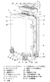
図1は、キャリーバッグカバー1を被せた状態のキャリーバッグ3、およびカバーケース40を示す斜視図である。
キャリーバッグ3は、前面ボディ3aと背面ボディ3bが閉じた状態で略立方体形状になるように形成されている。前面ボディ3aと背面ボディ3bは、左側面(図1の左奥側)に図示省略する蝶番が付いており、この蝶番を軸心として前面ボディ3aと背面ボディ3bが相対的に回転して開閉できるように構成されている。
FIG. 1 is a perspective view showing the
The
前面ボディ3aと背面ボディ3bの右側面(図1の右手前側)には、前面ボディ3aと背面ボディ3bを閉じた状態でロックできるリフトレバー6,6とサイドハンドル7が設けられている。このリフトレバー6,6により、前面ボディ3aと背面ボディ3bを閉じた状態で衝撃等を受けても開かないようにロックし、また、必要なときにロック解除して前面ボディ3aと背面ボディ3bを開けるようにしている。また、サイドハンドル7により、キャリーバッグ3を横向け(横長状態)にして持つことができ、普通人が腕を下へまっすぐ伸ばした状態でキャリーバッグ3が床に接触することなく運搬できる。
Lift levers 6 and 6 and a side handle 7 that can be locked in a state in which the front body 3a and the
キャリーバッグ3の背面ボディ3bの上面には、トップハンドル5(固定ハンドル)が設けられている。このトップハンドル5は、伸縮しないものであり、背面ボディ3bに固定されている。トップハンドル5により、縦長の状態でキャリーバッグ3を持ちあげて運搬できる。ただし、サイドハンドルと異なり、トップハンドル5を持った場合は、腕を曲げて持ち上げることでキャリーバッグ3を床に接触しない状態とすることができる。
A top handle 5 (fixed handle) is provided on the upper surface of the
また、キャリーバッグ3の背面ボディ3bの上面背面側には、上下方向に伸縮できる引き伸ばしハンドル4が設けられている。この引き伸ばしハンドル4は、2本のアーム4b,4bの上端を把持バー4aで接続した形状である。これにより、アーム4b,4bが背面ボディ3b内に収納された短縮状態と、アーム4b,4bが背面ボディ3bから引き出された伸長状態とを適宜変更できるようにしている。これにより、手荷物としてキャリーバッグ3を預ける場合はアーム4b,4bを収納状態として邪魔にならないようにし、キャリーバッグ3をキャスター9により転がして搬送する場合はアーム4b,4bを伸長状態として把持バー4aを持ちやすくすることができる。
In addition, on the back side of the upper surface of the
キャリーバッグ3の底面には、4ヶ所の角付近にキャスター9が合計4つ設けられている。このキャスター9は、平面視360度自由に向きを変えることができ、かつ、タイヤ9aを回転させることができる。これにより、任意の方向へキャリーバッグ3を水平移動させる際にタイヤ9aが回転し、楽な力で搬送することができ、向きを変えるときも容易に向きを変えることができる。
On the bottom surface of the
キャリーバッグカバー1は、内面サイズが、キャリーバッグ3の外面サイズとほぼ同じサイズ(同一サイズかそれより少し大きいサイズ)となるように伸縮性素材によって形成されている。この伸縮性素材は、例えばスウェットスーツ用の生地など、伸縮性を有する種々の生地とすることができる。なお、この伸縮性素材は、伸縮性に加えてクッション性も備えている素材であることが好ましく、スウェットスーツ用の生地とする、あるいは、スキューバダイビング等で用いられる生地とすることが好ましく、例えばクロロプレン、ラバー素材、ジャージー生地等の素材により形成することができる。
The
この伸縮性素材の厚みは、キャスター9を接地させた状態のキャリーバッグ3の底面から地面までの空間距離の1/3以下とする必要があり、1/4以下とすることが好ましく、1/6以下とするがより好ましく、1/8以下とすることが好適である。このような厚みにすることで、キャリーバッグカバー1の最底面が地面に接触して擦れることを防止できる。
The thickness of the stretchable material needs to be 1/3 or less of the space distance from the bottom surface of the
また、この伸縮性素材の厚みは、1mm以上とすることができ、2mm以上とすることが好ましく、3mm以上とすることがより好ましく、3〜5mmとすることが好適である。このような厚みとすることで、クッション性を高めることができ、手荒に扱われて他のキャリーバッグ等と衝突した際にキャリーバッグ3に凹み等が生じることを防止できる。
The thickness of the stretchable material can be 1 mm or more, preferably 2 mm or more, more preferably 3 mm or more, and preferably 3 to 5 mm. By setting it as such thickness, cushioning property can be improved and it can prevent that a dent etc. arise in the
キャリーバッグカバー1は、上面10と周面20を有しており、底面は解放されていて開口27が設けられている。
The
上面10は、キャリーバッグ3の上面の面積と同じか少し大きい程度の面積に形成されている。上面10は、背面側(図1の右奥側)に横長の引き伸ばしハンドル用窓孔11が設けられ、中央より少し背面側に引き伸ばしハンドル用窓孔11と同じ横幅の固定ハンドル用窓孔12が設けられている。引き伸ばしハンドル用窓孔11は、引き伸ばしハンドル4を挿通できるように引き伸ばしハンドル4の平面視の面積よりも大きく形成されている。固定ハンドル用窓孔12は、固定ハンドルの1つであるトップハンドル5を挿通できるようにトップハンドル5の平面視の面積よりも大きく形成されている。
The
なお、引き伸ばしハンドル用窓孔11と固定ハンドル用窓孔12の横幅は、同一でなくてもよく、それぞれ引き伸ばしハンドル4またはトップハンドル5を挿通できる大きさであればよい。
The lateral widths of the enlargement
この引き伸ばしハンドル用窓孔11および固定ハンドル用窓孔12により、利用者は、キャリーバッグカバー1を被せた状態でキャリーバッグ3の引き伸ばしハンドル4やトップハンドル5を持つことができる。従って、利用者や空港職員は、キャリーバッグカバー1を被せていない状態と同じように、キャリーバッグカバー1を被せたキャリーバッグ3の引き伸ばしハンドル4やトップハンドル5を持って運搬等することができる。
With the enlargement
周面20は、周方向がキャリーバッグ3の周面と同じか少し大きいくらいの大きさに形成され、上下方向(キャリーバッグ3に対する着脱方向)が接続用そで部25を除けばキャリーバッグ3の高さと同じ程度か少し短い程度に形成されている。この周面20は、孔が設けられておらず、上から下まで内周の大きさが同じ大きさとなるように構成されている。これにより、キャリーバッグ3(図1参照)に被せるときおよび取り外すときに、キャリーバッグ3のリフトレバー6,6やサイドハンドル7等の突出部にひっかかる部分がなく、スムーズに取り扱えるようにしている。
The
周面20の下端には、各面に接続用そで部25(25a〜25d)が延伸して設けられている。周面20の下端の角部は、接続用そで部25が存在せず、これによってキャスター9を露出するための露出窓27が形成されている。
At the lower end of the
周面20のうちの左右の側面(後述の右側面20bおよび左側面20d)と上面10には、固定ハンドル用窓孔12から露出窓27までを一直線に連結/分断可能にするジッパー16と、このジッパー16を開閉するスライダー15が設けられている。これにより、スライダー15を開状態に移動させると、ジッパー16が開き、ジッパー16よりキャリーバッグカバー1の内側に設けられている等幅の拡張シート17(図3(C)参照)が露出する。これにより、拡張シート17の幅だけキャリーバッグカバー1の周サイズを拡大することができ、より大きいキャリーバッグ3に被せることが可能となる。
A
カバーケース40は、ジッパー42とスライダー41によって開閉できる袋状で、キャリーバッグ3のアーム4b,4bに装着できるベルト43を備えている。このカバーケース40は、キャリーバッグカバー1を折りたたんで収納できる大きさに構成されている。これにより、キャリーバッグカバー1をカバーケース40に収納してキャリーバッグ3のアーム4b,4bに装着しておくことができる。使うときはスライダー41をスライドされてジッパー42を開き、内部のキャリーバッグカバー1を容易に取り出すことができる。また、カバーケース40を装着する部位が、キャリーバッグ3のうち、キャリーバッグカバー1が被せられないアーム4b,4bであるため、キャリーバッグカバー1が被せられていてもいなくても、カバーケース40をキャリーバッグ3に固定しておくことができ、利用者が便利に利用できる。
The
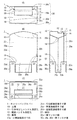
図2および図3は、不使用時のキャリーバッグカバー1の詳細な構造を説明する説明図である。図2(A)は平面図、図2(B)は正面図、図2(C)は右側面図、図2(D)は底面図、図3(A)は左側面図、図3(B)は背面図を示す。
2 and 3 are explanatory views illustrating the detailed structure of the
図2(A)に示すように、周面20は、正面20a、左側面20b、背面20c、および右側面20dにより構成されている。
As shown in FIG. 2A, the
正面20a、右側面20b、背面20c、および左側面20dの下端には、図2(B)及び図2(C)に示すように、それぞれ正面接続用そで部25a、右側面接続用そで部25b、背面接続用そで部25c、および左側面接続用そで部25dが、各正面20a、右側面20b、背面20c、および左側面20dの下端を延伸するようにして設けられている。
As shown in FIGS. 2 (B) and 2 (C), the
正面接続用そで部25aは、外面(表面)に面ファスナ雌30aが設けられている。この面ファスナ雌30aは、正面接続用そで部25aのほぼ全面に渡って設けられている。なお、面ファスナとは、面ファスナ雄と面ファスナ雌からなる、所謂マジックテープ(日本登録商標)と呼ばれるものである。面ファスナは、面ファスナ雄と面ファスナ雌が対向して重ねられると、互いに接続されて簡単には離れなくなり、強い力で引きはがすと離れるものであり、この重ねた接続状態と離した分離状態に何度でも切り替えできるものである。
The
この正面接続用そで部25aと背面接続用そで部25cは、前後方向接続用そで部として機能する。また、右側面接続用そで部25bおよび左側面接続用そで部25dは、左右方向接続用そで部として機能する。
The front connecting
図2(B)に示すように、右側面接続用そで部25bおよび左側面接続用そで部25dは、内面(裏面)に面ファスナ雄30bが設けられている。この面ファスナ雄30bは、右側面接続用そで部25bの基部側には設けられておらず、少なくとも先端側には設けられており、図示の例では基部側を少し除いてほぼ全面に渡って設けられている。
As shown in FIG. 2B, the right side connecting
図2(C)に示すように、背面接続用そで部25cは、内面(裏面)に面ファスナ雄30cが設けられている。この面ファスナ雄30cは、背面接続用そで部25cの先端付近に設けられている。すなわち、図3(B)に示すように、面ファスナ雄30cを背面接続用そで部25cの先端付近に設けている。これにより、面ファスナ雄30cを広い面ファスナ雌30aのどこかに接続することができる。
As shown in FIG. 2C, the
横断面が四角形となる周面20の各角部の下端は、図2(B)および図2(C)に示すように、開口27の縁となっている。この開口27の下方位置、すなわち、正面接続用そで部25a、右側面接続用そで部25b、背面接続用そで部25c、および左側面接続用そで部25dの各間の隙間部分には、キャリーバッグ3(図1参照)に被せた際にキャスター9(図1参照)が露出する隙間となるキャスター用窓23が設けられている。
As shown in FIGS. 2B and 2C, the lower end of each corner of the
正面接続用そで部25aおよび背面接続用そで部25cの少なくともキャスター9の内側付近の横幅は、キャスター9の内側間隔D1よりも短く形成されている。また、右側面接続用そで部25bおよび左側面接続用そで部25dの少なくともキャスター9の内側付近の横幅は、キャスター9の内側間隔D2よりも短く形成されている。これにより、正面接続用そで部25a、右側面接続用そで部25b、背面接続用そで部25c、および左側面接続用そで部25dがキャスター9の回転機能を妨げることないように、キャリーバッグカバー1をキャリーバッグ3に装着できるようにしている。
The lateral width of at least the inside of the
上面10、右側面20b、および左側面20dには、上面10の引き伸ばしハンドル用窓孔11の左右の横縁から背面20cと並行に右側面20b、および左側面20dの下端となる開口27まで真っ直ぐに伸びるジッパー16が左右対称に設けられている。このジッパー16は、上面10、右側面20b、および左側面20dを正面側と背面側の間で接続しているものであり、スライダ11が上下動されると開閉を行うものである。すなわち、ジッパー16は、上面10、右側面20b、および左側面20dを前面側と背面側とに分離可能に接続しており、スライダー15によって開状態にされると、ジッパー16が離間して間に拡張シート17が露出する。これによってキャリーバッグカバー1を前後方向に広げることができ、前後方向の厚みが厚いキャリーバッグ3に被せることも可能となる。
The
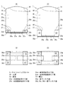
図4(A)の正面図、および図4(B)の底面図は、対応可能な最も小さいサイズのキャリーバッグ3に被せることを想定したキャリーバッグカバー1の図を示している。この図に示すように、正面接続用そで部25a、右側面接続用そで部25b、背面接続用そで部25c、および左側面接続用そで部25dを湾曲若しくは屈曲させ、互いに面ファスナ30a,30b,30c,30が雄雌で重なりあうようにして接続する。このとき、開口27の下方にはキャスター用窓23が設けられている。
The front view of FIG. 4 (A) and the bottom view of FIG. 4 (B) show a view of the
図4(C)の正面図、図4(D)の底面図に示すように、正面接続用そで部25a、右側面接続用そで部25b、背面接続用そで部25c、および左側面接続用そで部25dをできるだけ長く(つまり基部側を少なく残して)内側へ折り曲げる。これにより、キャスター9(図1参照)を露出させながら、右側面接続用そで部25b、背面接続用そで部25c、および左側面接続用そで部25dを接続することができる。また、この状態のとき、正面接続用そで部25aに設けられた面ファスナ30cの底面側に、右側面接続用そで部25bおよび左側面接続用そで部25dの面ファスナ雄30b,30dを接触させて接続し、さらにその底面側に背面接続用そで部25cを重ねてファスナ30cを接触させて接続する。これにより、左右の右側面接続用そで部25bおよび左側面接続用そで部25dの上から(底面側から)、背面接続用そで部25cを重ねて接続することができる。なお、この面ファスナ30a,30b,30c,30dは、接続固定手段として機能する。
As shown in the front view of FIG. 4C and the bottom view of FIG. 4D, the
図4(D)の正面図および図4(E)の底面図は、対応可能な大きいサイズのキャリーバッグ3(図1参照)にキャリーバッグカバー1を被せることを想定したキャリーバッグカバー1の図を示している。この図に示すように、正面接続用そで部25a、右側面接続用そで部25b、背面接続用そで部25c、および左側面接続用そで部25dを、基部側がなるべく多く残された状態で湾曲若しくは屈曲させ、互いに面ファスナ30a,30b,30c,30が雄雌で重なりあうようにして接続する。このとき、開口27の下方にはキャスター用窓23が設けられている。
The front view of FIG. 4 (D) and the bottom view of FIG. 4 (E) are diagrams of the
これにより、キャスター9(図1参照)を露出させながら、右側面接続用そで部25b、背面接続用そで部25c、および左側面接続用そで部25dを接続することができる。また、この状態のとき、正面接続用そで部25aに設けられた面ファスナ30cの底面側に、右側面接続用そで部25bおよび左側面接続用そで部25dの面ファスナ雄30b,30dを接触させて接続し、同様に背面接続用そで部25cの面ファスナ雄30cを接触させて接続する。これにより、キャリーバッグカバー1を縦長にした状態にでき、通常よりも縦に長いキャリーバッグ3を収納することができる。
Thus, the right
キャリーバッグカバー1を構成する各シートの継ぎ目及び縁には、全て糸で縫われた縫い目18が設けられている。
A
以上の構成を有することにより、キャリーバッグカバー1は、キャリーバッグ3に被せてキャリーバッグ3を傷がつかないように保護できる。キャリーバッグカバー1は、伸縮性の素材により形成されているため、キャリーバッグ3の大きさが多少異なっていても、素材そのものが伸びてキャリーバッグカバー1をキャリーバッグ3に被せることができる。
By having the above configuration, the
また、キャリーバッグカバー1は、ある程度の厚みがあってクッション性を有する素材で構成されているため、金属製のキャリーバッグ3等の衝突によるへこみや、プラスチック製のキャリーバッグ3等の衝突による破損を防止することができる。
Since the
また、素材が伸びても入らないような大きさのキャリーバッグ3の場合、厚み方向や横幅方向については、スライダー15を移動させてジッパー16を開き、キャリーバッグケース1の内周サイズを大きくしてキャリーバッグ3を収納することができる。
Further, in the case of the
また、素材が伸びても入らないような高さのキャリーバッグ3の場合、正面接続用そで部25a、右側面接続用そで部25b、背面接続用そで部25c、および左側面接続用そで部25dの接続位置を変化させることで対応することができる。
Further, in the case of the
すなわち、図4(A)および図4(B)に示すように、正面接続用そで部25aの面ファスナ雌30aが前後方向(基部から先端の方向,長さ方向)に長く形成されていることにより、背面接続用そで部25cの面ファスナ雄30cを前後方向(基部から先端の方向,長さ方向)の任意の位置で接続することができ、正面接続用そで部25aの面ファスナ雌30aが左右方向(幅方向)に幅広に形成されていることにより、右側面接続用そで部25bの面ファスナ雄30b、および左側面接続用そで部25dの面ファスナ雄30dを左右方向(基部から先端の方向,長さ方向)の任意の位置で接続できる。
That is, as shown in FIG. 4A and FIG. 4B, the front fastener female 30a of the front connecting
換言すると、正面接続用そで部25a、右側面接続用そで部25b、背面接続用そで部25c、および左側面接続用そで部25dの接続部位までの長さが最小限となるように接続した状態から、図4(C)および図4(D)に示すように、正面接続用そで部25a、右側面接続用そで部25b、背面接続用そで部25c、および左側面接続用そで部25dの接続部位までの長さが最大限となるように接続した状態まで、キャリーバッグ4の高さに合わせて自由な長さに接続することができる。
In other words, the length of the
また、正面接続用そで部25aおよび背面接続用そで部25cにより、前後方向に底面を被覆して保護できると共に、右側面接続用そで部25bおよび左側面接続用そで部25dにより、左右方向に底面を被覆して保護することができる。これにより、キャリーバッグ3の底面の4つ角に設けられたキャスター9を露出させつつ、底面の4辺を保護することができ、段差等でキャリーバッグ3の底辺の角が衝突したときも傷つかないように保護できる。
Further, the front connecting
また、底面をこれらの接続用そで部25(25a〜25d)でしっかり止めていることにより、キャリーバッグカバー1がキャリーバッグ3から外れてしまうことを防止できる。これにより、例えば空港貨物として手荒に扱われベルトコンベアで搬送されても、キャリーバッグカバー1が外れてしまって保護機能を失いキャリーバッグ3に傷が付くといったトラブルを防止できる。
Moreover, it can prevent that the
また、横幅が狭い方である右側面接続用そで部25bおよび左側面接続用そで部25dの長さが、キャリーバッグ3の底面側へ折り曲げた際に重ならない程度に形成されているため、キャリーバッグ3の底面から地面の間でキャリーバッグカバー1が厚くなって地面に接触することを防止できる。すなわち、対応可能で最も小さなサイズのキャリーバッグ3を収納したときに、正面接続用そで部25a、右側面接続用そで部25b、背面接続用そで部25c、および左側面接続用そで部25dが全て底面側で重なると、4枚分の厚みとなるために、地面からの離間距離が短くなる。そうすると、地面のがたつきや段差によってっキャリーバッグカバー1の最底面が地面に接触しやすくなる。これに対して、対応可能で最も小さなサイズのキャリーバッグ3を収納したときでも右側面接続用そで部25bと左側面接続用そで部25dが重なりあうことがないため、底部が厚くなりすぎることがなく、地面からの離間距離を確保することができる。
Further, the length of the right
また、正面接続用そで部25aの面ファスナ雌30aを左右方向に幅広に設けているため、図4(B)および図4(D)に示したように、右側面接続用そで部25bの面ファスナ雄30bと左側面接続用そで部25dが左右方向の長さを様々に変化させても接続することができる。
Further, since the front fastener female 30a of the front connecting
また、背面接続用そで部25cにも面ファスナ雄30cを設けているため、正面接続用そで部25aの面ファスナ雌30aに接続することができる。すなわち、雌側(雄雌の一方)は、正面接続用そで部25aの面ファスナ雌30aのみであり、残り3つの接続用そで部に設けられた面ファスナが全て雄側(雄雌の他方)の面ファスナ雄30b,30c,30dとなっている。これにより、広い面積に形成されている面ファスナ雌30aに、他の全ての面ファスナ雄30b,30c,30dを接続することができ、止める位置を自由自在に変更できる。従って、前後左右方向の大きさや高さが異なる様々なキャリーバッグ3にキャリーバッグカバー1を被せても、しっかりと底面で接続して止めることができる。
Moreover, since the hook-and-
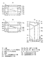
図5は、他の実施例のキャリーバッグカバーを説明する説明図である。
図5(A)は、実施例2のキャリーバッグカバー51の底面図である。図示するように、このキャリーバッグカバー51は、実施例1の右側面接続用そで部25b(図4(B)参照)、および左側面接続用そで部25d(図4(B)参照)の代わりに、図5(A)に示す右側面接続用そで部75b、および左側面接続用そで部75dを備えている。実施例1の右側面接続用そで部25b、および左側面接続用そで部25dが方形であったことに対して、右側面接続用そで部75b、および左側面接続用そで部75dは、斜面77d,77bをそれぞれ有する三角形に形成されている。右側面接続用そで部75b、および左側面接続用そで部75dは、互いの斜面77d,77bが対向するように配置され、固定される。すなわち、右側面接続用そで部75b、および左側面接続用そで部75dは、基部から先端に向かった横幅が先細りする形状に形成されており、接続時に一方の先端側が他方の基部側の横に位置するようにして相手側と重ならない形状に形成されている。この構成により、右側面接続用そで部75bと左側面接続用そで部75dは、厚み方向に重ねることなく幅方向(図5(A)の上下方向)に並べることができるため、キャリーバッグ3(図1参照)の底部で全体が厚くなることを防止できると共に、止める位置の調節可能範囲も長くすることができる。
FIG. 5 is an explanatory diagram for explaining a carry bag cover according to another embodiment.
FIG. 5A is a bottom view of the
その他の構成については、実施例1と同一であるため、同一要素に同一符号を付してその詳細な説明を省略する。 Since other configurations are the same as those of the first embodiment, the same reference numerals are given to the same elements, and detailed descriptions thereof are omitted.
以上の構成により、キャリーバッグカバー51は、実施例1のキャリーバッグカバー1と同一の作用効果を奏することができる。また、右側面接続用そで部75bと左側面接続用そで部75dが斜面77d,77bを有して互いに厚み方向に重なることなく固定できるため、より背の高いキャリーバッグ3(図1参照)からより背の低いキャリーバッグ3(図1参照)まで対応することができる。
With the above configuration, the
図5(B)、図5(C)は、実施例3のキャリーバッグカバー61を説明する説明図である。図5(B)は、キャリーバッグカバー61の底面図であり、図5(C)は、キャリーバッグカバー61の右側面図である。
FIG. 5B and FIG. 5C are explanatory views illustrating the
この実施例3は、実施例1の背面接続用そで部25c(図2参照)を備えず、実施例1の正面接続用そで部25a(図2参照)をキャリーバッグ3に対する着脱方向へさらに長くした正面接続用そで部75aを備えている。正面接続用そで部75aの外面には、広い面積に渡って面ファスナ雌80aが設けられている。この面ファスナ雌80aには、右側面接続用そで部75bの内面に設けられた面ファスナ雄80bと、左側面接続用そで部75dの内面に設けられた面ファスナ雄80dが接続固定される。正面接続用そで部75aの先端の内面には、背面20cの下方外面に設けられた面ファスナ雄80cに接続固定される面ファスナ雌80eが設けられている。この面ファスナ雌80eは、面ファスナ雄80cを接続固定する接続相手として機能する。
The third embodiment does not include the rear connecting
その他の構成については、実施例1若しくは実施例2と同一であるため、同一要素に同一符号を付してその詳細な説明を省略する。 Since other configurations are the same as those in the first embodiment or the second embodiment, the same components are denoted by the same reference numerals, and detailed description thereof is omitted.
以上の構成により、キャリーバッグカバー51は、実施例1のキャリーバッグカバー1と同一の作用効果を奏することができる。また、右側面接続用そで部75bと左側面接続用そで部75dが斜面77d,77bを有して互いに厚み方向に重なることなく固定できるため、より背の高いキャリーバッグ3(図1参照)からより背の低いキャリーバッグ3(図1参照)まで対応することができる。
With the above configuration, the
また、背面20cに正面接続用そで部75aを接続することにより、実施例1の背面接続用そで部25cを削除できる。
Further, by connecting the front connecting
また、キャリーバッグ3の底面より下方で重ねて接続固定されるものは、正面接続用そで部75aと右側面接続用そで部75bと左側面接続用そで部75dのみとなり、しかも右側面接続用そで部75bと左側面接続用そで部75dは互いに重ならない状態で使用される。そうすると、キャリーバッグ3の底面より下方で重ねて接続固定される枚数は最大2枚となり、底部での厚みを削減することができる。
Further, only the
この発明は、本実施形態に限られず他の様々な実施形態とすることができる。
例えば、面ファスナは、雄と雌を逆にする、ボタンとボタンホールにする、あるいファスナップボタンの雄と雌とするなど、適宜の構成とすることも可能である。ただし、面ファスナとすることで、正確に位置決めせずとも接続固定でき、かつ、任意の長さで容易かつ迅速に接続固定することが可能となる。また、外面に面ファスナ雌30a,80a,80eを配置し、内面に面ファスナ雄30b,30c,30d,80b,80c,80dを配置することで、面ファスナ雄が露出してセーター等の意図しない物が接続されることを防止できる。従って、面ファスナを採用することで利便性が向上し、利用者の満足度を向上させることができる。
The present invention is not limited to this embodiment, and can be various other embodiments.
For example, the hook-and-loop fastener may have an appropriate configuration such that males and females are reversed, buttons and buttonholes, or male and female snap-snap buttons. However, by using a hook-and-loop fastener, connection and fixing can be performed without positioning accurately, and connection and fixing can be easily and quickly performed at an arbitrary length. Further, by arranging the
なお、キャリーバッグカバー1の大きさは、キャリーバッグ3よりも少し小さい大きさとしても良い。この場合でも、素材の伸縮力によって広がり、キャリーバッグ3に被せることができる。この場合、キャリーバッグ3によりぴったりとフィットするキャリーバッグカバー1を提供できる。
The size of the
また、キャリーバッグカバー1は、1〜3泊用の小型キャリーバッグに適した小型サイズ、4〜7泊用の中型キャリーバッグに適した中型サイズ、7〜14泊用の大型キャリーバッグに適した大型サイズといったように、いくつかの種類を設けても良い。この場合、適切な大きさのキャリーバッグカバー1を用いることで、各種類の中でも様々な大きさの違いがある多種多様なキャリーケースに対して適切に装着することができる。
Moreover, the
また、ジッパー16とスライダー15を設けず、これによって前後方向に広がる機能も排除してシンプルな構成としてもよい。この場合も素材の伸縮性によってある程度の大きさの違いに対応できる上に、シンプルな構成で安価に提供することが可能になる。
Further, the
この発明は、キャリーバッグカバーを製造販売する産業、および空港等でキャリーバッグカバーを販売あるいは貸し出す産業など、キャリーバッグのカバーに関する産業に利用することができる。 The present invention can be used in industries related to carry bag covers, such as industries that manufacture and sell carry bag covers, and industries that sell or rent carry bag covers at airports and the like.
1,51,61…キャリーバッグカバー
3…キャリーバッグ
3a…前面ボディ
3b…背面ボディ
4…引き伸ばしハンドル
5…トップハンドル
9…キャスター
10…上面
11…引き伸ばしハンドル用窓孔
12…固定ハンドル用窓孔
20…周面
25…接続用そで部
25a…正面接続用そで部
25b,75b…右側面接続用そで部
25c…背面接続用そで部
25d,75d…左側面接続用そで部
27…開口
30a,80a,80e…面ファスナ雌
30b,30c,30d,80b,80c,80d…面ファスナ雄
D1,D2…内側間隔
1, 51, 61 ... Carry
Claims (6)
全体が伸縮性を有する素材により形成され、
上面の一辺に、前記キャリーバッグに設けられた出し入れ自在の引き伸ばしハンドルが挿通される引き伸ばしハンドル用窓孔が設けられ、
前記周面における少なくとも一つの面に下端が延伸された接続用そで部が設けられ、
前記接続用そで部は、
前記キャリーバッグを収納した状態で自身の両横に位置する前記キャスターの内側部分が当該キャスターの内側間隔よりも狭い横幅に形成されるとともに、
基部から先端の間の少なくとも一部に接続相手に接続固定される接続固定手段が設けられている
キャリーバッグカバー。 A bag-like carry bag cover having an upper surface and a peripheral surface and having an opening on the bottom surface with a size capable of accommodating a body of a carry bag provided with a caster on the bottom surface,
The whole is made of a stretchable material,
On one side of the upper surface, there is provided a window hole for an enlargement handle through which an extendable handle that is provided in the carry bag can be inserted and removed,
A connecting sleeve having a lower end extended on at least one surface of the peripheral surface,
The connecting sleeve is
The inner portions of the casters located on both sides of the carry bag in a state in which the carry bags are stored are formed with a lateral width narrower than the inner spacing of the casters,
A carry bag cover provided with a connection fixing means to be connected and fixed to a connection partner at least at a part between a base and a tip.
基部から先端までの長さが前記接続相手に接続可能な最小限の長さよりもさらに長く形成され、
前記接続固定手段と前記接続相手の少なくとも一方は、前記キャリーバッグを収納した状態で他方に対して前記接続可能な最小限の長さの位置から最大限の長さの位置まで広範囲に渡って設けられている。
請求項1記載キャリーバッグカバー。 The connecting sleeve is
The length from the base to the tip is formed longer than the minimum length that can be connected to the connection partner,
At least one of the connection fixing means and the connection partner is provided over a wide range from the position of the minimum length connectable to the position of the maximum length with respect to the other in a state where the carry bag is stored. It has been.
The carry bag cover according to claim 1.
前記キャリーバッグを収納した状態での正面および背面の少なくとも一方に設けられた前後方向接続用そで部と、右側面および左側面の少なくとも一方に設けられた左右方向接続用そで部を有し、
前記前後方向接続用そで部および前記左右方向接続用そで部が前記キャリーバッグの底面を前後および左右に渡って保護する構成である
請求項1または2記載のキャリーバッグカバー。 The connecting sleeve is
A front-rear connecting sleeve provided on at least one of the front and rear surfaces in the state in which the carry bag is stored, and a left-right connecting sleeve provided on at least one of the right side and the left side ,
The carry bag cover according to claim 1 or 2, wherein the front / rear direction connecting sleeve and the left / right connecting sleeve protect the bottom surface of the carry bag in the front / rear and left / right directions.
2つ設けられてそれぞれが前記周面における対向面に対向配置され、
前記キャリーバッグの底面側へ湾曲または屈曲した状態で互いが重ならない長さまたは形状に形成されている
請求項3記載のキャリーバッグカバー。 Of the front and rear connecting sleeves and the left and right connecting sleeves, the narrower one is
Two are provided, each facing the opposing surface of the peripheral surface,
The carry bag cover according to claim 3, wherein the carry bag cover is formed in a length or shape that does not overlap each other in a state of being bent or bent toward the bottom surface side of the carry bag.
前記2つ設けられた前記前後方向接続用そで部および前記左右方向接続用そで部のうち横幅が狭い方の前記接続固定手段が接続される接続相手が設けられた
請求項4記載のキャリーバッグカバー。 Of the front and rear connecting sleeves and the left and right connecting sleeves,
5. The carry according to claim 4, wherein a connection partner is provided to which the connection fixing means having a narrower width is connected between the two front and rear connecting sleeves and the left and right connecting sleeves. Bag cover.
前記固定ハンドル用窓孔は、
前記周面には設けられず前記上面に設けられている
請求項1から5のいずれか1つに記載のキャリーバッグカバー。 A fixed handle window hole is provided for inserting a fixed handle provided in the carry bag,
The fixed handle window hole is
The carry bag cover according to claim 1, wherein the carry bag cover is not provided on the peripheral surface but provided on the upper surface.
Priority Applications (1)
| Application Number | Priority Date | Filing Date | Title |
|---|---|---|---|
| JP2016084860A JP6571584B2 (en) | 2016-04-20 | 2016-04-20 | Carry bag cover |
Applications Claiming Priority (1)
| Application Number | Priority Date | Filing Date | Title |
|---|---|---|---|
| JP2016084860A JP6571584B2 (en) | 2016-04-20 | 2016-04-20 | Carry bag cover |
Publications (2)
| Publication Number | Publication Date |
|---|---|
| JP2017192572A true JP2017192572A (en) | 2017-10-26 |
| JP6571584B2 JP6571584B2 (en) | 2019-09-04 |
Family
ID=60154381
Family Applications (1)
| Application Number | Title | Priority Date | Filing Date |
|---|---|---|---|
| JP2016084860A Active JP6571584B2 (en) | 2016-04-20 | 2016-04-20 | Carry bag cover |
Country Status (1)
| Country | Link |
|---|---|
| JP (1) | JP6571584B2 (en) |
Cited By (4)
| Publication number | Priority date | Publication date | Assignee | Title |
|---|---|---|---|---|
| RU189328U1 (en) * | 2019-02-28 | 2019-05-21 | Василий Васильевич Николаев | CASE FOR CASE |
| USD856680S1 (en) | 2018-06-12 | 2019-08-20 | Eduardo Acosta Favati | Luggage protective cover |
| WO2023248340A1 (en) * | 2022-06-21 | 2023-12-28 | 株式会社Kurs | Carry bag cover |
| US12082669B1 (en) * | 2023-08-22 | 2024-09-10 | John Ray Marello | Eco-friendly luggage wrap with tamper-evident feature for secure, convenient travel |
Citations (5)
| Publication number | Priority date | Publication date | Assignee | Title |
|---|---|---|---|---|
| JPH07308217A (en) * | 1994-05-16 | 1995-11-28 | Natsuko Hirata | Cover for suitcase |
| JP3135705U (en) * | 2007-06-26 | 2007-09-27 | 株式会社ヤマプラス | Method for fastening chair cover and sewing structure |
| US7458452B2 (en) * | 2006-02-17 | 2008-12-02 | Edward Beakey | Luggage cover |
| JP3185271U (en) * | 2013-05-29 | 2013-08-08 | 耕一 平田 | Bag cover |
| JP3190330U (en) * | 2014-01-31 | 2014-05-08 | アンドウ株式会社 | Wheel cover |
-
2016
- 2016-04-20 JP JP2016084860A patent/JP6571584B2/en active Active
Patent Citations (5)
| Publication number | Priority date | Publication date | Assignee | Title |
|---|---|---|---|---|
| JPH07308217A (en) * | 1994-05-16 | 1995-11-28 | Natsuko Hirata | Cover for suitcase |
| US7458452B2 (en) * | 2006-02-17 | 2008-12-02 | Edward Beakey | Luggage cover |
| JP3135705U (en) * | 2007-06-26 | 2007-09-27 | 株式会社ヤマプラス | Method for fastening chair cover and sewing structure |
| JP3185271U (en) * | 2013-05-29 | 2013-08-08 | 耕一 平田 | Bag cover |
| JP3190330U (en) * | 2014-01-31 | 2014-05-08 | アンドウ株式会社 | Wheel cover |
Cited By (5)
| Publication number | Priority date | Publication date | Assignee | Title |
|---|---|---|---|---|
| USD856680S1 (en) | 2018-06-12 | 2019-08-20 | Eduardo Acosta Favati | Luggage protective cover |
| RU189328U1 (en) * | 2019-02-28 | 2019-05-21 | Василий Васильевич Николаев | CASE FOR CASE |
| WO2023248340A1 (en) * | 2022-06-21 | 2023-12-28 | 株式会社Kurs | Carry bag cover |
| US12082669B1 (en) * | 2023-08-22 | 2024-09-10 | John Ray Marello | Eco-friendly luggage wrap with tamper-evident feature for secure, convenient travel |
| WO2025043124A1 (en) * | 2023-08-22 | 2025-02-27 | Marello John Ray | Eco-friendly luggage wrap with tamper-evident feature for secure, convenient travel |
Also Published As
| Publication number | Publication date |
|---|---|
| JP6571584B2 (en) | 2019-09-04 |
Similar Documents
| Publication | Publication Date | Title |
|---|---|---|
| US7213692B2 (en) | Carry-on baggage container with a folding chair | |
| JP5833591B2 (en) | Luggage | |
| US10159322B2 (en) | Luggage cover with carrying element | |
| US7849984B2 (en) | Collapsible bag mounting structure and collapsible bag associated therewith | |
| JP6571584B2 (en) | Carry bag cover | |
| US9427031B2 (en) | Storable poncho and related method | |
| JP3067634U (en) | Shoulder bag | |
| JP6073225B2 (en) | Folding bag | |
| US20180192754A1 (en) | Accessory Caddy for Luggage | |
| KR20130142892A (en) | Foldable travel bags and methods to manufacture foldable travel bags | |
| US20250009052A1 (en) | Wearable towel foldable into a backpack | |
| US20150173475A1 (en) | Storage assembly | |
| US20150367502A1 (en) | Collapsible Toolbag for Use With Hand Truck | |
| US20090236379A1 (en) | bag having a shopping trolley insert | |
| KR101245161B1 (en) | Foldable suit case | |
| JPH0228059A (en) | Baby carriage | |
| US20210070535A1 (en) | Transport case for a folding bicycle | |
| JP4864601B2 (en) | Body cover for motorcycle | |
| US20080203745A1 (en) | Protective covering apparatus for vehicles | |
| JPH07308217A (en) | Cover for suitcase | |
| WO2023248340A1 (en) | Carry bag cover | |
| JP3161850U (en) | Stop | |
| JP3682653B2 (en) | bag | |
| JP3116322U (en) | Protective cover for clothes | |
| JP3199144U (en) | Wheelchair bag |
Legal Events
| Date | Code | Title | Description |
|---|---|---|---|
| A521 | Request for written amendment filed |
Free format text: JAPANESE INTERMEDIATE CODE: A523 Effective date: 20160627 |
|
| A521 | Request for written amendment filed |
Free format text: JAPANESE INTERMEDIATE CODE: A523 Effective date: 20160704 |
|
| A621 | Written request for application examination |
Free format text: JAPANESE INTERMEDIATE CODE: A621 Effective date: 20180328 |
|
| A977 | Report on retrieval |
Free format text: JAPANESE INTERMEDIATE CODE: A971007 Effective date: 20181206 |
|
| A131 | Notification of reasons for refusal |
Free format text: JAPANESE INTERMEDIATE CODE: A131 Effective date: 20181218 |
|
| A601 | Written request for extension of time |
Free format text: JAPANESE INTERMEDIATE CODE: A601 Effective date: 20190213 |
|
| A521 | Request for written amendment filed |
Free format text: JAPANESE INTERMEDIATE CODE: A523 Effective date: 20190409 |
|
| TRDD | Decision of grant or rejection written | ||
| A01 | Written decision to grant a patent or to grant a registration (utility model) |
Free format text: JAPANESE INTERMEDIATE CODE: A01 Effective date: 20190723 |
|
| A61 | First payment of annual fees (during grant procedure) |
Free format text: JAPANESE INTERMEDIATE CODE: A61 Effective date: 20190808 |
|
| R150 | Certificate of patent or registration of utility model |
Ref document number: 6571584 Country of ref document: JP Free format text: JAPANESE INTERMEDIATE CODE: R150 |
|
| R250 | Receipt of annual fees |
Free format text: JAPANESE INTERMEDIATE CODE: R250 |
|
| R250 | Receipt of annual fees |
Free format text: JAPANESE INTERMEDIATE CODE: R250 |