JP2017192409A - Washing machine - Google Patents

Washing machine Download PDF

Info

Publication number
JP2017192409A
JP2017192409A JP2016082583A JP2016082583A JP2017192409A JP 2017192409 A JP2017192409 A JP 2017192409A JP 2016082583 A JP2016082583 A JP 2016082583A JP 2016082583 A JP2016082583 A JP 2016082583A JP 2017192409 A JP2017192409 A JP 2017192409A
Authority
JP
Japan
Prior art keywords
washing
course
water
stirring blade
tub
Prior art date
Legal status (The legal status is an assumption and is not a legal conclusion. Google has not performed a legal analysis and makes no representation as to the accuracy of the status listed.)
Granted
Application number
JP2016082583A
Other languages
Japanese (ja)
Other versions
JP6620061B2 (en
Inventor
祐太朗 林
Yutaro Hayashi
祐太朗 林
渡辺 光
Hikari Watanabe
光 渡辺
博紀 長谷川
Hiroki Hasegawa
博紀 長谷川
裕之 小池
Hiroyuki Koike
裕之 小池
和俊 片根
Kazutoshi Katane
和俊 片根
丈 曽我
Jo Soga
丈 曽我
高田 健太郎
Kentaro Takada
健太郎 高田
Current Assignee (The listed assignees may be inaccurate. Google has not performed a legal analysis and makes no representation or warranty as to the accuracy of the list.)
Hitachi Appliances Inc
Original Assignee
Hitachi Appliances Inc
Priority date (The priority date is an assumption and is not a legal conclusion. Google has not performed a legal analysis and makes no representation as to the accuracy of the date listed.)
Filing date
Publication date
Application filed by Hitachi Appliances Inc filed Critical Hitachi Appliances Inc
Priority to JP2016082583A priority Critical patent/JP6620061B2/en
Publication of JP2017192409A publication Critical patent/JP2017192409A/en
Application granted granted Critical
Publication of JP6620061B2 publication Critical patent/JP6620061B2/en
Active legal-status Critical Current
Anticipated expiration legal-status Critical

Links

Images

Abstract

PROBLEM TO BE SOLVED: To provide a washing machine that ensures a washing power while suppressing a damage on cloth or a cloth entanglement of laundry (especially, clothing of a delicate material, clothing easily losing a shape, fashionable clothing).SOLUTION: The washing machine includes a washing tub, an impeller blade provided on a bottom of the washing tub, a driving device for rotary driving the washing tub and the impeller blade, and water supply means for supplying water into the washing tub. The washing machine has a first washing course that is a standard course and a second washing course that is different from the first washing course. When the first washing course is selected, washing is performed by rotating the impeller blade in a state where water has been supplied into the washing tub at a first set level of water by the water supply means. When the second washing course is selected, washing is performed by rotating the impeller blade in a state where water has been supplied into the washing tub at a second set level of water that is higher than the first set level of water by the water supply means.SELECTED DRAWING: Figure 12

Description

本発明は、洗濯機に関する。   The present invention relates to a washing machine.

特許文献1には「布傷み・縮み・型くずれ・からみ等の極めて少ないおしゃれ着洗浄と通常の洗浄の両方を可能とする洗濯機の実現を目的としている。」と記載されている。   Patent Document 1 describes that “It is aimed to realize a washing machine that can perform both fashionable clothes washing and normal washing with very little fabric damage, shrinkage, shape loss, entanglement, etc.”.

特開平8−191982号公報JP-A-8-191982

従来の洗濯機で、洗濯槽を固定してパルセータを回転させて洗浄を実施する場合、洗濯物(デリケート素材の衣類、型くずれし易い衣類、オシャレ着衣類など)とパルセータや洗濯槽との間に擦れが生じ、布傷みや布絡み、さらには、縮み、型くずれ等が極めて大きくなってしまう課題がある。   When washing with a conventional washing machine with the washing tub fixed and rotating the pulsator, between the pulsator and the washing tub There is a problem in that rubbing occurs and fabric damage, fabric entanglement, shrinkage, shape loss, and the like become extremely large.

もうひとつの洗濯手段である洗濯槽を低速回転させて洗浄を実施する場合、衣類および洗濯液は洗濯槽の回転に合わせて回転するため、衣類が水の抵抗を受けにくく、洗浄効率が悪いという課題がある。また、例えばウール素材の衣類などでは、水面に洗濯物が浮いてしまうため、衣類に洗濯液が十分に浸透しない可能性があり、洗濯槽内に入れて使用する洗濯キャップなどで衣類を抑えつけて洗濯することが望ましいとされている。   When washing is performed by rotating the washing tub, which is another means of washing, at low speed, the clothes and washing liquid rotate according to the rotation of the washing tub. There are challenges. Also, for example, in woolen clothing, the laundry may float on the surface of the water, so there is a possibility that the washing liquid will not permeate the clothing sufficiently. It is considered desirable to wash.

そこで、本発明では、前記した従来の課題を解決するものであり、洗濯物(特に、デリケート素材の衣類、型くずれし易い衣類、オシャレ着衣類など)の布傷みや布絡みなどを抑えつつ洗浄力を確保した洗濯機を提供することを目的とする。   Therefore, the present invention solves the above-described conventional problems, and is capable of cleaning while preventing fabric damage or entanglement of laundry (especially delicate material clothing, easily deformed clothing, fashionable clothing, etc.). It aims at providing the washing machine which secured.

本発明は、その一例として、洗濯槽と、前記洗濯槽の底に設けられる攪拌翼と、前記洗濯槽と前記攪拌翼を回転駆動させる駆動装置と、前記洗濯槽に給水する給水手段と、を備える洗濯機において、標準コースである第1の洗濯コースと、前記第1の洗濯コースとは異なる第2の洗濯コースと、を有し、前記第1の洗濯コースが選択された場合、前記給水手段により前記洗濯槽に第1の設定水位まで給水した状態で、前記攪拌翼を回転させて洗いを実行し、前記第2の洗濯コースが選択された場合、前記給水手段により前記洗濯槽に前記第1の設定水位よりも高い第2の設定水位まで給水した状態で、前記攪拌翼を回転させて洗いを実行する、ことを特徴とする。   The present invention includes, as an example, a washing tub, a stirring blade provided at the bottom of the washing tub, a driving device that rotationally drives the washing tub and the stirring wing, and a water supply unit that supplies water to the washing tub. In the washing machine provided, the first washing course as a standard course and a second washing course that is different from the first washing course, and when the first washing course is selected, the water supply In the state where the washing tub is supplied to the first set water level by the means, the agitating blade is rotated to perform washing, and when the second washing course is selected, the water supply means supplies the washing tub to the washing tub. Washing is performed by rotating the stirring blade in a state where water is supplied to a second set water level higher than the first set water level.

本発明によれば、洗濯物(特に、デリケート素材の衣類、型くずれし易い衣類、オシャレ着衣類など)の布傷みや布絡みなどを抑えつつ洗浄力を確保した洗濯機を提供出来る。   ADVANTAGE OF THE INVENTION According to this invention, the washing machine which ensured the detergency while suppressing the cloth damage, fabric entanglement, etc. of the laundry (especially the clothing of delicate material, the clothing which is easy to lose shape, the fashionable clothing, etc.) can be provided.

本実施形態の洗濯機の内部構成を示す概略図である。It is the schematic which shows the internal structure of the washing machine of this embodiment. 本実施形態に係る洗濯槽の内部構成を示す縦断面図である。It is a longitudinal cross-sectional view which shows the internal structure of the washing tub which concerns on this embodiment. 攪拌翼を取り外した洗濯槽の内部を示す断面図である。It is sectional drawing which shows the inside of the washing tub from which the stirring blade was removed. 攪拌翼の裏側を示す斜視図である。It is a perspective view which shows the back side of a stirring blade. 循環水路の入口と径方向リブとの位置関係を示す断面図である。It is sectional drawing which shows the positional relationship of the inlet_port | entrance of a circulation water channel, and a radial direction rib. 比較例としての攪拌翼の裏側を示す斜視図である。It is a perspective view which shows the back side of the stirring blade as a comparative example. 周方向リブによる水の流れを示し、(a)は本実施形態、(b)は比較例である。The flow of the water by the circumferential direction rib is shown, (a) is this embodiment, (b) is a comparative example. シャワー拡散のイメージ図を示し、(a)は本実施形態、(b)は比較例である。The image figure of shower diffusion is shown, (a) is this embodiment, (b) is a comparative example. 操作パネルを示す概略図である。It is the schematic which shows an operation panel. 標準コースに係る洗浄方式の行程動作を示すフローチャートである。It is a flowchart which shows process operation | movement of the washing | cleaning system which concerns on a standard course. ドライコースに係る洗浄方式の行程動作を示すフローチャートである。It is a flowchart which shows process operation | movement of the washing | cleaning system which concerns on a dry course. デリケートコースに係る洗浄方式の行程動作を示すフローチャートである。It is a flowchart which shows process operation | movement of the washing | cleaning system which concerns on a delicate course. 本洗いでの攪拌翼の回転数を標準コース、ドライコース、デリケートコースで比較した図である。It is the figure which compared the rotation speed of the stirring blade in main washing in a standard course, a dry course, and a delicate course. 本洗いでの洗濯槽内の水位の変化を標準コース、ドライコース、デリケートコースで比較した図である。It is the figure which compared the change of the water level in the washing tub in the main washing in the standard course, the dry course, and the delicate course. 攪拌翼3と動きと衣類の動きとの関係を示す図である。It is a figure which shows the relationship between the stirring blade 3, a motion, and the motion of clothing.

以下、本発明を実施するための形態(以下「実施形態」という)について、適宜図面を参照しながら詳細に説明する。なお、以下では、洗濯、すすぎ、脱水を行うことができる洗濯機(いわゆる、全自動洗濯機)を例に挙げて説明するが、洗濯、すすぎ、脱水、乾燥を行うことができる洗濯機(いわゆる、縦型の洗濯乾燥機)に適用することもできる。   Hereinafter, modes for carrying out the present invention (hereinafter referred to as “embodiments”) will be described in detail with reference to the drawings as appropriate. In the following, a washing machine (so-called fully automatic washing machine) that can perform washing, rinsing, and dehydrating will be described as an example. However, a washing machine that can perform washing, rinsing, dehydrating and drying (so-called washing machine) The present invention can also be applied to a vertical washer / dryer.

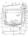
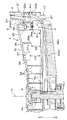
図1は、本実施形態の洗濯機の内部構成を示す概略図である。   FIG. 1 is a schematic view showing the internal configuration of the washing machine of the present embodiment.

図1に示すように、洗濯機1は、略箱形の鋼板製の外枠(筺体)5内に、洗濯槽2と、洗濯槽2の底に設けられる攪拌翼3と、洗濯水を循環させる循環水路Rと、を備えて構成されている。   As shown in FIG. 1, a washing machine 1 circulates a washing tub 2, a stirring blade 3 provided at the bottom of the washing tub 2, and washing water in an outer frame (housing) 5 made of a substantially box-shaped steel plate. And a circulating water channel R.

洗濯槽2は、有底円筒形状を呈し、胴板21、この胴板21の底部に設けられる底板22、胴板21の上部に設けられるバランスリング23などを備えて構成されている。   The washing tub 2 has a bottomed cylindrical shape, and includes a body plate 21, a bottom plate 22 provided on the bottom of the body plate 21, a balance ring 23 provided on the top of the body plate 21, and the like.

攪拌翼3(脈動翼盤、パルセータともいう)は、略円盤状に形成され、洗濯槽2の底部に設けられている。また、攪拌翼3は、駆動装置6によって回転可能に支持されている。これにより、洗い時やすすぎ時に、攪拌翼3を回転させることで洗濯水を洗濯物12ごと攪拌することができる。   The stirring blade 3 (also referred to as a pulsating blade or a pulsator) is formed in a substantially disk shape and is provided at the bottom of the washing tub 2. The stirring blade 3 is rotatably supported by the driving device 6. Accordingly, the washing water can be stirred together with the laundry 12 by rotating the stirring blade 3 at the time of washing or rinsing.

循環水路Rは、洗濯槽2の壁面に設けられ、攪拌翼3の回転によって洗濯水(水)を、洗濯槽2の底部から洗濯槽2の上部に押し上げて、洗濯槽2の内部に戻して循環するように構成されている。また、循環水路Rは、洗濯槽2の壁面の複数箇所に設けられている。   The circulation channel R is provided on the wall surface of the washing tub 2, and the washing water (water) is pushed up from the bottom of the washing tub 2 to the top of the washing tub 2 by the rotation of the stirring blade 3, and returned to the inside of the washing tub 2. It is configured to circulate. Circulating water channels R are provided at a plurality of locations on the wall surface of the washing tub 2.

また、洗濯機1は、外枠5の枠体内に、洗濯槽2を同軸上に内包する外槽7を備えている。この外槽7は、合成樹脂製で有底円筒状に形成され、外枠5の上端から吊り下げ支持するコイルバネや弾性ゴムからなる防振装置8などによって垂下防振支持されている。また、外槽7の底部外側には、排水弁13および排水ホース11が設けられ、外槽7の底部に設けられた排水口7aと排水弁13を介して排水ホース11と接続されている。   The washing machine 1 also includes an outer tub 7 that coaxially encloses the washing tub 2 in the frame of the outer frame 5. The outer tub 7 is made of a synthetic resin and is formed in a bottomed cylindrical shape, and is supported in a suspended and antivibration manner by a coil spring that is suspended and supported from the upper end of the outer frame 5 or a vibration isolator 8 that is made of elastic rubber. Further, a drain valve 13 and a drain hose 11 are provided outside the bottom of the outer tub 7, and are connected to the drain hose 11 via a drain port 7 a and a drain valve 13 provided at the bottom of the outer tub 7.

また、洗濯機1は、制御手段であるコントロールユニット19、給水手段である電磁給水弁16、水位を検知する感圧式の水位センサ15などを備えている。洗濯工程等を行う際、コントロールユニット19の指令により、電磁給水弁16を開き、外槽7内に洗濯水が給水される。所定の水位となったことが水位センサ15により検知されると、コントロールユニット19の指令により電磁給水弁16を閉め、給水を停止する。また、脱水工程等を行う際、コントロールユニット19の指令により排水弁13が開かれ、外槽7内の洗濯水は、排水ホース11の他端から洗濯機1の機外へ排出される。   The washing machine 1 also includes a control unit 19 that is a control means, an electromagnetic water supply valve 16 that is a water supply means, a pressure-sensitive water level sensor 15 that detects the water level, and the like. When performing the washing process or the like, the electromagnetic water supply valve 16 is opened by the command of the control unit 19, and the washing water is supplied into the outer tub 7. When the water level sensor 15 detects that the water level has reached a predetermined level, the electromagnetic water supply valve 16 is closed by a command from the control unit 19 to stop water supply. Moreover, when performing a dehydration process etc., the drain valve 13 is opened by the instruction | command of the control unit 19, and the wash water in the outer tub 7 is discharged | emitted from the other end of the drain hose 11 out of the washing machine 1.

外枠5の上部には、合成樹脂製の上面カバー9が設けられ、外枠5の下部には、合成樹脂製のベース部材10が設けられている。また、上面カバー9の中央部には、洗濯物12等を出し入れする洗濯物投入口9aを有し、この洗濯物投入口9aを開閉するための蓋体9bが設けられている。また、上面カバー9の後部には、水道栓と接続される給水ホース接続口17が設けられている。給水ホース接続口17は、電磁給水弁16と接続されている。   An upper cover 9 made of synthetic resin is provided on the upper part of the outer frame 5, and a base member 10 made of synthetic resin is provided on the lower part of the outer frame 5. A central portion of the top cover 9 has a laundry input port 9a for taking in and out the laundry 12 and the like, and a lid 9b for opening and closing the laundry input port 9a. Further, a water supply hose connection port 17 connected to a water tap is provided at the rear portion of the top cover 9. The water supply hose connection port 17 is connected to the electromagnetic water supply valve 16.

また、外槽7の内周と洗濯槽2外周との間には隙間があり、この隙間に洗濯物等が入らなくするとともに、外槽7全体の剛性を保つために、外槽7の上端にはバランスリング23の上面を覆うような槽カバー18が設けられている。   In addition, there is a gap between the inner circumference of the outer tub 7 and the outer circumference of the washing tub 2, and the upper end of the outer tub 7 is kept in order to prevent the laundry from entering the gap and to maintain the rigidity of the entire outer tub 7. Is provided with a tank cover 18 that covers the upper surface of the balance ring 23.

駆動装置6は、外槽7の底部外側に鋼板製の取付けベース14を介して取り付けられている。また、駆動装置6は、駆動用モータおよび減速機構を介して攪拌翼3を駆動するように構成されている。この駆動装置6は、洗濯槽2を静止若しくは回転を固定させた状態で攪拌翼3を正逆両方向に回転させる攪拌モード、洗濯槽2と攪拌翼3を一体的に同一方向に回転させる脱水モードを選択的に駆動できるように構成されている。   The drive device 6 is attached to the outside of the bottom of the outer tub 7 via a steel plate attachment base 14. The drive device 6 is configured to drive the stirring blade 3 via a drive motor and a speed reduction mechanism. The driving device 6 is configured to rotate the stirring blade 3 in both forward and reverse directions while the washing tub 2 is stationary or fixed, and a dehydration mode in which the washing tub 2 and the stirring blade 3 are integrally rotated in the same direction. Can be selectively driven.

また、駆動装置6は、洗濯槽2を静止させない状態(洗濯槽2の回転を固定しないが、駆動装置6で洗濯槽2を直接回転できない状態)で攪拌翼3を正逆両方向に回転させる中立モードも選択的に駆動できるように構成されている。   Further, the driving device 6 is neutral in which the agitating blade 3 is rotated in both forward and reverse directions in a state where the washing tub 2 is not stationary (the rotation of the washing tub 2 is not fixed but the washing tub 2 cannot be directly rotated by the driving device 6). The mode can also be selectively driven.

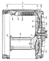
図2は、本実施形態に係る洗濯槽の内部構成を示す縦断面図である。なお、図2では、脱水孔21a(図1参照)の図示を省略している。   FIG. 2 is a longitudinal sectional view showing the internal configuration of the washing tub according to the present embodiment. In FIG. 2, the dehydration hole 21a (see FIG. 1) is not shown.

図2に示すように、胴板21は、ステンレス鋼板を円筒状に形成したものであり、周壁に洗濯物12に含まれている洗濯水を遠心力にて洗濯物12と分離し排出するための複数の脱水孔21a(図1参照、一部のみ図示)が形成されている。   As shown in FIG. 2, the body plate 21 is a stainless steel plate formed in a cylindrical shape, and the washing water contained in the laundry 12 on the peripheral wall is separated from the laundry 12 by centrifugal force and discharged. A plurality of dewatering holes 21a (see FIG. 1, only part of which are shown) are formed.

また、胴板21には、循環水路Rを構成する循環流路部材24が取り付けられている。この循環流路部材24は、合成樹脂などの略板状の部材で形成されるとともに、所定の幅で上下方向に延びて構成されている。   The body plate 21 is attached with a circulation channel member 24 that constitutes the circulation channel R. The circulation flow path member 24 is formed of a substantially plate-shaped member such as a synthetic resin, and is configured to extend in the vertical direction with a predetermined width.

また、胴板21には、循環流路部材24とは別の位置に、循環水路Rを構成する循環流路部材25が取り付けられている。この循環流路部材25には、着脱式の糸くず捕集部材26が取り付けられている。この糸くず捕集部材26は、複数の開口26aが形成され、開口26aが配置されている領域にリントフィルタ(不図示)が設けられている。   Further, a circulation channel member 25 that constitutes the circulation channel R is attached to the body plate 21 at a position different from the circulation channel member 24. A detachable lint collecting member 26 is attached to the circulation channel member 25. The lint collecting member 26 has a plurality of openings 26a, and a lint filter (not shown) is provided in a region where the openings 26a are disposed.

底板22は、合成樹脂製で胴板21の下部を塞ぐ皿形状の部材であり、洗濯槽2の底面を構成する底部22aと、この底部22aの外周縁から上方に延びて側面を構成する側部22bと、を有し、胴板21の下端部に固定されている。また、底部22aには、外槽7の底と通じる貫通孔22cが複数形成されている。   The bottom plate 22 is made of a synthetic resin and is a dish-shaped member that closes the lower portion of the body plate 21, and includes a bottom portion 22a that forms the bottom surface of the washing tub 2, and a side that extends upward from the outer peripheral edge of the bottom portion 22a and forms a side surface. Part 22b, and is fixed to the lower end of the body plate 21. In addition, a plurality of through holes 22c communicating with the bottom of the outer tub 7 are formed in the bottom portion 22a.

バランスリング23は、合成樹脂などでリング状に形成され、胴板21の上端部(上縁部)に固定されている。また、バランスリング23は、胴板21の内壁面よりも径方向の内側に突出するように配置され、バランスリング23の内径が、胴板21の内径よりも小さくなるように構成されている。また、バランスリング23は、内部に比重の大きな流体(塩水など)を封入して構成され、洗濯槽2の回転時に洗濯物の偏りなどによって偏心が生じたときに、流体の移動によって偏心を打ち消し、回転のバランスを維持する機能を有している。   The balance ring 23 is formed in a ring shape with synthetic resin or the like, and is fixed to the upper end portion (upper edge portion) of the body plate 21. The balance ring 23 is disposed so as to protrude radially inward from the inner wall surface of the trunk plate 21, and the inner diameter of the balance ring 23 is configured to be smaller than the inner diameter of the trunk plate 21. Further, the balance ring 23 is configured by enclosing a fluid having a large specific gravity (such as salt water) therein, and cancels the eccentricity due to the movement of the fluid when the eccentricity occurs due to the unevenness of the laundry when the washing tub 2 rotates. , Has the function of maintaining the balance of rotation.

攪拌翼3は、底板22の内部(洗濯槽2の内底部)を覆う直径を有する略円盤形状であり、中央部が回転軸方向の上方に盛り上がるとともに、周方向に沿って上下に波打つように構成されている。また、攪拌翼3は、周縁部の一部が上向きに迫り上がるように湾曲して形成されている。また、攪拌翼3には、表面側と裏面側とを貫通する孔3aが複数個所に形成され、円形のディンプル部3bや径方向に延びる突条部3cが複数箇所に形成されている。   The stirring blade 3 has a substantially disk shape having a diameter covering the inside of the bottom plate 22 (inner bottom portion of the washing tub 2), and the center portion rises upward in the rotation axis direction and undulates vertically along the circumferential direction. It is configured. Further, the stirring blade 3 is formed to be curved so that a part of the peripheral edge is pushed upward. Further, the stirring blade 3 is formed with a plurality of holes 3a penetrating the front surface side and the back surface side, and a circular dimple portion 3b and a radially extending ridge portion 3c are formed at a plurality of locations.

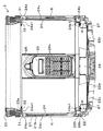
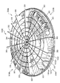
図3は、攪拌翼を取り外した洗濯槽の内部を示す断面図である。なお、図3は、糸くず捕集部材26を正面から見た断面図である。   FIG. 3 is a cross-sectional view showing the inside of the washing tub with the stirring blades removed. FIG. 3 is a cross-sectional view of the waste thread collecting member 26 as viewed from the front.

図3に示すように、循環流路部材24は、上端24aがバランスリング23の近傍まで延び、下端24bが底板22の凹部に入り込む位置まで延びている。また、循環流路部材24の上端24aには、径方向内側に樹脂で一体に曲げ形成されたつば部24a1が形成されている。このつば部24a1の先端は、バランスリング23よりも径方向内側に突出しない位置に設定されている。また、循環流路部材24の下端24bには、樹脂で一体に曲げ形成されるとともに底板22と嵌合するつば部24b1が径方向内側に突出して形成されている。   As shown in FIG. 3, the circulation channel member 24 has an upper end 24 a extending to the vicinity of the balance ring 23, and a lower end 24 b extending to a position where it enters the recess of the bottom plate 22. Further, at the upper end 24 a of the circulation flow path member 24, a flange portion 24 a 1 is formed that is integrally bent with resin on the radially inner side. The tip of the collar portion 24 a 1 is set at a position that does not protrude radially inward from the balance ring 23. Further, at the lower end 24b of the circulation flow path member 24, a flange portion 24b1 that is integrally bent with resin and fits with the bottom plate 22 is formed to protrude radially inward.

また、循環流路部材24の裏面には、樹脂で一体に形成された導水路24cが形成され、循環流路部材24と胴板21の内壁面21bとの間で循環水路Rを形成している。すなわち、循環流路部材24の裏面には、左右方向(周方向)に離間して配置される一対のリブ(図示省略)が胴板21に向けて突出して形成されるとともに、循環流路部材24を胴板21に固定するための固定部(図示省略)が設けられている。このリブにパッキン(不図示)を装着して循環流路部材24の内壁面に密着させるとともに、循環流路部材24を胴板21に固定部を介して固定することで、入口27から流入した洗濯水が途中で液漏れすることなく、循環流路部材24の上端まで流通できるようになっている。   Further, a water conduit 24 c formed integrally with resin is formed on the back surface of the circulation channel member 24, and a circulation channel R is formed between the circulation channel member 24 and the inner wall surface 21 b of the trunk plate 21. Yes. That is, a pair of ribs (not shown) spaced apart in the left-right direction (circumferential direction) are formed on the back surface of the circulation channel member 24 so as to protrude toward the body plate 21, and the circulation channel member A fixing portion (not shown) for fixing 24 to the body plate 21 is provided. A packing (not shown) is attached to the rib so as to be in close contact with the inner wall surface of the circulation flow path member 24, and the circulation flow path member 24 is fixed to the body plate 21 through a fixing portion, thereby flowing from the inlet 27. The washing water can flow up to the upper end of the circulation flow path member 24 without leaking in the middle.

また、糸くず捕集部材26が設けられた循環流路部材25の裏面には、樹脂で一体に形成された導水路(不図示)が形成され、循環流路部材25と胴板21の内壁面(不図示)との間で循環水路(不図示)を形成している。なお、本実施形態の循環流路部材25は、洗濯水を上端まで循環水路Rが形成されているものではなく、糸くず捕集部材26の開口26aから洗濯水を洗濯槽2内に散水することで循環させるものである。なお、このような構成の循環流路部材25に限定されるものではなく、循環流路部材25の糸くず捕集部材26の上方に、洗濯水を吐出させるスリット状の吐出口が設けられたものであってもよい。   Further, a water conduit (not shown) formed integrally with a resin is formed on the back surface of the circulation channel member 25 provided with the lint collecting member 26, and the inside of the circulation channel member 25 and the body plate 21 is formed. A circulation channel (not shown) is formed between the wall surface (not shown). The circulation channel member 25 of the present embodiment does not have the circulation channel R formed up to the upper end of the washing water, and sprays the washing water into the washing tub 2 from the opening 26a of the waste thread collecting member 26. It is to be circulated. In addition, it is not limited to the circulation flow path member 25 of such a structure, The slit-shaped discharge port which discharges washing water was provided above the waste thread collection member 26 of the circulation flow path member 25. It may be a thing.

前記した循環流路部材24の鉛直方向の下方に位置する洗濯槽2の底には、洗濯水を循環水路Rに導入するための入口(導入口)27が設けられている。入口27が設けられている底板22は、底部22aから側部22bにかけてR形状を有するように湾曲して形成されている。これにより、洗濯水の流れの向きを鉛直方向に延びる循環水路Rに円滑に変えることができる。また、入口27の高さ寸法Hは、つば部24b1の下面から鉛直方向の下方に下ろした直線が底板22と接するまでの長さである。また、入口27の高さ位置Hm(図5参照)とは、つば部24b1の下面の高さ、換言すると入口27の上端の高さである。   An inlet (introduction port) 27 for introducing the washing water into the circulation water channel R is provided at the bottom of the washing tub 2 positioned below the circulation channel member 24 in the vertical direction. The bottom plate 22 provided with the inlet 27 is formed to be curved so as to have an R shape from the bottom 22a to the side 22b. Thereby, the direction of the flow of the washing water can be smoothly changed to the circulation water channel R extending in the vertical direction. Further, the height dimension H of the inlet 27 is a length until a straight line drawn downward in the vertical direction from the lower surface of the flange portion 24b1 contacts the bottom plate 22. The height position Hm (see FIG. 5) of the inlet 27 is the height of the lower surface of the collar portion 24b1, in other words, the height of the upper end of the inlet 27.

また、循環水路Rの上端には、鉛直方向の上方に向けて開口して形成された吐出口31が形成されている。この吐出口31は、バランスリング23の下面23aと対向するように配置されている。これにより、吐出口31から吐出された洗濯水がバランスリング23の下面23aに衝突することで、つば部24a1と下面23aとの間に形成された隙間32から洗濯水が洗濯槽2内に向けて吐出(散水)されるようになっている。   In addition, a discharge port 31 is formed at the upper end of the circulating water channel R so as to open upward in the vertical direction. The discharge port 31 is disposed so as to face the lower surface 23 a of the balance ring 23. Thus, the washing water discharged from the discharge port 31 collides with the lower surface 23a of the balance ring 23, so that the washing water is directed into the washing tub 2 from the gap 32 formed between the collar portion 24a1 and the lower surface 23a. Are discharged (sprinkled).

また、前記した循環流路部材25の鉛直方向の下方に位置する洗濯槽2の底には、洗濯水を循環水路に導入するための入口(導入口)28(図3参照)が形成されている。入口28から導入された洗濯水は、循環流路部材25と胴板21との間に形成された導水路(不図示)を通って、糸くず捕集部材26内に導入されて糸くずが捕集された後、開口26aから洗濯槽2内に散水されるようになっている。   In addition, an inlet (inlet port) 28 (see FIG. 3) for introducing the washing water into the circulation channel is formed at the bottom of the washing tub 2 positioned below the circulation channel member 25 in the vertical direction. Yes. The washing water introduced from the inlet 28 passes through a water conduit (not shown) formed between the circulation flow path member 25 and the body plate 21 and is introduced into the waste thread collecting member 26 so that the waste thread is removed. After being collected, water is sprayed into the washing tub 2 from the opening 26a.

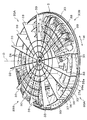
図4は、攪拌翼の裏側を示す斜視図である。   FIG. 4 is a perspective view showing the back side of the stirring blade.

図4に示すように、攪拌翼3の裏面(下面)には、回転軸中心Oから径方向Dに延びる複数の裏羽根33(径方向リブ)が形成されている。換言すると、裏羽根33が回転軸中心Oから放射状に形成されている。この裏羽根33は、板形状であり、攪拌翼3の裏面から鉛直方向の下方(図4では上方)に向けて突出して形成されている。また、裏羽根33は、周方向Wに略等角度で配置されるように構成されている。   As shown in FIG. 4, a plurality of back blades 33 (radial ribs) extending in the radial direction D from the rotation axis center O are formed on the back surface (lower surface) of the stirring blade 3. In other words, the back blades 33 are formed radially from the rotation axis center O. The back blade 33 has a plate shape and is formed so as to protrude downward in the vertical direction (upward in FIG. 4) from the back surface of the stirring blade 3. Further, the back blade 33 is configured to be arranged at a substantially equal angle in the circumferential direction W.

本実施形態では、攪拌翼3の上方(図2参照)に盛り上がった2つの領域の裏面に、裏羽根群33A,33Aが形成されている。これにより、裏羽根33間に取り込む水量を多く確保することができる。それぞれの裏羽根群33Aは、5枚の裏羽根33で構成され、約90度の角度範囲で配置されている。裏羽根群33Aは、循環させる洗濯水を取り込む機能だけではなく、洗濯槽2に洗濯物12が投入されて攪拌翼3が撓み変形するのを抑制する補強部材としての機能も有している。   In the present embodiment, back blade groups 33A and 33A are formed on the back surfaces of the two regions raised above the stirring blade 3 (see FIG. 2). Thereby, a large amount of water taken in between the back blades 33 can be secured. Each back blade group 33A is composed of five back blades 33, and is arranged in an angle range of about 90 degrees. The back blade group 33A has not only a function of taking in the washing water to be circulated, but also a function as a reinforcing member for suppressing the laundry 12 from being poured into the washing tub 2 and bending and deforming the stirring blade 3.

裏羽根群33Aと裏羽根群33Aとの間の領域には、裏羽根群33B,33Bが形成されている。この裏羽根群33Bは、攪拌翼3の下方(図2参照)に凹んだ2つの領域の裏面に形成されている。また、裏羽根群33Bは、3枚の裏羽根で構成され、約90度の角度範囲内に配置されている。この裏羽根群33Bは、主に攪拌翼3が撓み変形するのを抑制する補強部材として機能している。   Back blade groups 33B and 33B are formed in a region between the back blade group 33A and the back blade group 33A. The back blade group 33B is formed on the back surface of two regions recessed below the stirring blade 3 (see FIG. 2). The back blade group 33B is composed of three back blades and is disposed within an angle range of about 90 degrees. The back blade group 33B mainly functions as a reinforcing member that suppresses the stirring blade 3 from being bent and deformed.

また、攪拌翼3の裏面の中心側(半径の約2分の1の領域)には、回転中心軸Oに同心円状または略同心円状に形成される円環リブ34,34,34が形成されている。これにより、攪拌翼3および裏羽根群33A,33A,33B,33Bを補強することができる。   In addition, annular ribs 34, 34, 34 formed concentrically or substantially concentrically around the rotation center axis O are formed on the center side of the back surface of the stirring blade 3 (region of about a half of the radius). ing. Thereby, the stirring blade 3 and the back blade group 33A, 33A, 33B, 33B can be reinforced.

また、攪拌翼3の裏面(下面)には、周方向Wに延びる外周側リブ35および内周側リブ36,37が径方向Dに間隔を置いて形成されている。また、外周側リブ35および内周側リブ36,37は、それぞれ攪拌翼3の曲率と略同じ曲率で湾曲して形成されている。   Further, an outer peripheral rib 35 and inner peripheral ribs 36 and 37 extending in the circumferential direction W are formed on the back surface (lower surface) of the stirring blade 3 at intervals in the radial direction D. Further, the outer peripheral side rib 35 and the inner peripheral side ribs 36 and 37 are formed to be curved with substantially the same curvature as that of the stirring blade 3.

外周側リブ35は、外周側に位置する周方向リブであり、裏羽根群33Aの周方向Wの一端の裏羽根33から他端の裏羽根33にかけて延びて、すべての裏羽根33と樹脂によって一体に形成されている。また、外周側リブ35は、裏羽根群33Aの各裏羽根33の先端側に位置している。なお、裏羽根33の先端側とは、裏羽根33の外周側の端部、または裏羽根33の外周側の端部の近傍を意味している。   The outer circumferential rib 35 is a circumferential rib located on the outer circumferential side, and extends from the rear blade 33 at one end in the circumferential direction W of the rear blade group 33A to the rear blade 33 at the other end. It is integrally formed. Moreover, the outer peripheral side rib 35 is located in the front end side of each back blade 33 of the back blade group 33A. Note that the front end side of the back blade 33 means an end portion on the outer peripheral side of the back blade 33 or the vicinity of an end portion on the outer peripheral side of the back blade 33.

内周側リブ36,37は、外周側リブ35よりも内周側に位置する周方向リブであり、内周側リブ36が内周側リブ37よりも外周側に位置するように構成されている。また、内周側リブ36,37は、外周側リブ35よりも上下方向の長さが短く形成されている。また、内周側リブ36は、内周側リブ37よりも上下方向の長さが長く形成されている。   The inner peripheral side ribs 36 and 37 are circumferential ribs positioned on the inner peripheral side with respect to the outer peripheral side rib 35, and are configured such that the inner peripheral side rib 36 is positioned on the outer peripheral side with respect to the inner peripheral side rib 37. Yes. Further, the inner peripheral ribs 36 and 37 are formed to be shorter in the vertical direction than the outer peripheral rib 35. Further, the inner circumferential side rib 36 is formed to be longer in the vertical direction than the inner circumferential side rib 37.

内周側リブ36,37は、裏羽根群33Aの5枚の裏羽根33のうちの中央の3枚の裏羽根33と一体に形成されている。   The inner peripheral ribs 36 and 37 are integrally formed with the three back blades 33 at the center of the five back blades 33 of the back blade group 33A.

図5は、循環水路の入口と径方向リブとの位置関係を示す断面図である。なお、図5は、裏羽根群33Aの5枚の裏羽根33のうちの中央の裏羽根33が正面となるように切断したときの断面図を示している。   FIG. 5 is a cross-sectional view showing the positional relationship between the inlet of the circulating water channel and the radial rib. FIG. 5 shows a cross-sectional view of the back blade group 33A when the center back blade 33 of the five back blades 33 is cut to the front.

図5に示すように、攪拌翼3の表面は、中央部が若干盛り上がり形状であるとともに、円環リブ34の位置から外周側(径方向外側)に向けて上昇する傾斜面3dを有している。図5に示す位置では、攪拌翼3の外周縁部は、底板22の上端22dよりも上方に位置している。また、攪拌翼3の外周縁部には、入口27に向けて延びる垂下部3eが形成されている。この垂下部3eの先端(下端)は、入口27(つば部24b1)の上方に位置するとともに、循環流路部材24の表面との間に隙間Sが形成されるように構成されている。この隙間Sの寸法は、運転時に攪拌翼3が循環流路部材24に接触しない最小の距離に設定されている。   As shown in FIG. 5, the surface of the stirring blade 3 has a slightly raised shape at the center, and has an inclined surface 3d that rises from the position of the annular rib 34 toward the outer peripheral side (radially outward). Yes. In the position shown in FIG. 5, the outer peripheral edge of the stirring blade 3 is located above the upper end 22 d of the bottom plate 22. A drooping portion 3 e extending toward the inlet 27 is formed on the outer peripheral edge of the stirring blade 3. The tip (lower end) of the hanging portion 3e is positioned above the inlet 27 (the collar portion 24b1), and is configured such that a gap S is formed between the surface of the circulation flow path member 24. The dimension of the gap S is set to the minimum distance at which the stirring blade 3 does not contact the circulation channel member 24 during operation.

外周側リブ35および内周側リブ36,37は、それぞれ下方に位置する底板22の底部22aに向けて延び、互いに平行に形成されている。また、外周側リブ35および内周側リブ36,37は、攪拌翼3の半径の半分(二分の一)よりも外周側に位置している。   The outer peripheral side rib 35 and the inner peripheral side ribs 36 and 37 extend toward the bottom portion 22a of the bottom plate 22 positioned below and are formed in parallel to each other. Moreover, the outer peripheral side rib 35 and the inner peripheral side ribs 36 and 37 are located on the outer peripheral side with respect to half the radius of the stirring blade 3 (1/2).

外周側リブ35の先端(下端)35aは、循環水路Rの入口27の高さ位置Hm(つば部24b1の下面)よりも底部22aの側(底側)に位置している。換言すると、外周側リブ35の先端(下端)35aは、入口27の上端部(高さ位置Hm)よりも下方に位置し、径方向から見たときに入口27と外周側リブ35とが一部で重なるように構成されている。また、外周側リブ35の先端(下端)35aは、入口27の高さ寸法Hの半分の高さ位置よりも上方に位置している。これにより、洗濯水が隙間Sから逃げる量を抑制でき、しかも入口27に導入される洗濯水の流量が減少するのを抑制できる。   The front end (lower end) 35a of the outer peripheral side rib 35 is located on the side of the bottom 22a (bottom side) from the height position Hm of the inlet 27 of the circulating water channel R (the lower surface of the flange portion 24b1). In other words, the front end (lower end) 35a of the outer peripheral side rib 35 is located below the upper end portion (height position Hm) of the inlet 27, and the inlet 27 and the outer peripheral side rib 35 are identical when viewed from the radial direction. It is comprised so that it may overlap in a part. Further, the front end (lower end) 35 a of the outer peripheral side rib 35 is located above a height position that is half the height dimension H of the inlet 27. As a result, the amount of washing water that escapes from the gap S can be suppressed, and the flow rate of the washing water introduced into the inlet 27 can be suppressed from decreasing.

内周側リブ36,37の先端(下端)36a,37aは、外周側リブ35の先端(下端)35aよりも底部22aから離れる側に位置している。換言すると、内周側リブ36,37の先端(下端)36a,37aは、外周側リブ35の先端(下端)35aよりも上方に位置している。また、内周側リブ36の先端(下端)36aは、内周側リブ37の先端(下端)37aよりも底部22a側に位置している。   The tips (lower ends) 36a, 37a of the inner peripheral ribs 36, 37 are located on the side farther from the bottom portion 22a than the tips (lower ends) 35a of the outer peripheral rib 35. In other words, the tips (lower ends) 36a, 37a of the inner peripheral ribs 36, 37 are positioned above the tips (lower ends) 35a of the outer peripheral ribs 35. Further, the front end (lower end) 36 a of the inner peripheral side rib 36 is located closer to the bottom 22 a than the front end (lower end) 37 a of the inner peripheral side rib 37.

また、攪拌翼3の回転軸中心Oには、駆動装置6(図1参照)の回転軸6aと接続されるボス3fが設けられている。このボス3fは、攪拌翼3の裏面に、下方に向けて突出して形成されている。ボス3fの先端(下端)を基準位置Hsとした場合、外周側リブ35の先端35aの高さ寸法をH1とし、内周側リブ36の先端36aの高さ寸法をH2とし、内周側リブ37の先端37aの高さ寸法をH3とすると、H1<H2<H3の関係になっている。   A boss 3f connected to the rotation shaft 6a of the drive device 6 (see FIG. 1) is provided at the rotation shaft center O of the stirring blade 3. The boss 3f is formed on the back surface of the stirring blade 3 so as to protrude downward. When the tip (lower end) of the boss 3f is the reference position Hs, the height of the tip 35a of the outer peripheral rib 35 is H1, the height of the tip 36a of the inner rib 36 is H2, and the inner rib When the height dimension of the tip 37a of 37 is H3, the relationship is H1 <H2 <H3.

また、外周側リブ35の攪拌翼3の裏面からの鉛直方向の長さは、裏面から基準位置Hsまでの長さの半分(二分の一)よりも長く設定されている。また、内周側リブ36,37の攪拌翼3の裏面からの鉛直方向の長さは、裏面から基準位置Hsまでの長さの半分(二分の一)以下に設定されている。   Moreover, the length of the vertical direction from the back surface of the stirring blade 3 of the outer peripheral side rib 35 is set longer than the half (1/2) of the length from a back surface to the reference position Hs. Further, the length in the vertical direction from the back surface of the stirring blade 3 of the inner peripheral ribs 36 and 37 is set to be equal to or less than a half (1/2) of the length from the back surface to the reference position Hs.

このような循環流路部材24を設けた洗濯機1では、底板22の内周側(洗濯槽2の内底部)と、攪拌翼3の裏面に設けられた裏羽根33とで形成されたポンプ室P(図1参照)に、循環水路Rが連通するようにして構成されている。   In the washing machine 1 provided with such a circulation flow path member 24, a pump formed by the inner peripheral side of the bottom plate 22 (inner bottom portion of the washing tub 2) and the back blade 33 provided on the back surface of the stirring blade 3. A circulation channel R is configured to communicate with the chamber P (see FIG. 1).

このように構成された洗濯機1では、例えば、洗濯物12を洗濯槽2に投入し、電源スイッチをオンし、スタートスイッチ(図示せず)をオンすると、コントロールユニット19の指令により、電磁給水弁16が制御されて所定水位まで給水され、洗濯(洗い)工程に移行する。洗濯工程では、駆動装置6のモータが洗濯水流に応じて右回転・休止・左回転・休止とコントロールユニット19によって制御されて回転する。このように制御された駆動装置6のモータの回転は攪拌翼3に伝えられ、攪拌翼3および裏羽根33が回転し、洗濯槽2内の洗濯物12と洗濯水が撹拌され、洗濯物12が洗浄される。なお、駆動装置6のモータの回転速度は、例えば、毎分90〜150回転に設定される。   In the washing machine 1 configured as described above, for example, when the laundry 12 is put into the washing tub 2, the power switch is turned on, and the start switch (not shown) is turned on, an electromagnetic water supply is performed according to a command from the control unit 19. The valve 16 is controlled to supply water to a predetermined water level, and the process proceeds to a washing (washing) process. In the washing process, the motor of the driving device 6 is rotated by being controlled by the control unit 19 in the right rotation / pause / left rotation / pause according to the washing water flow. The rotation of the motor of the driving device 6 controlled in this way is transmitted to the stirring blade 3, the stirring blade 3 and the back blade 33 rotate, the laundry 12 and the washing water in the washing tub 2 are stirred, and the laundry 12 Is washed. In addition, the rotational speed of the motor of the drive device 6 is set to 90 to 150 revolutions per minute, for example.

一方、攪拌翼3の裏側の洗濯水は、攪拌翼3の回転による裏羽根33の回転によって遠心力で外側に押し出され、循環水路R内を押し上げられ、吐出口31から上方に向けて間欠的に吐出される。吐出口31から吐出された洗濯水は、バランスリング23の下面23aに衝突することで、洗濯水の向きが洗濯槽2の内側に変えられ、洗濯槽2内に間欠的に注がれる。なお、攪拌翼3の裏羽根33によって洗濯水が循環水路Rに押し出されると、その後、底板22の底部22aに設けた外槽7に通じる貫通孔22c(図2参照)から新しい洗濯水が供給される。   On the other hand, the washing water on the back side of the stirring blade 3 is pushed outward by centrifugal force by the rotation of the back blade 33 due to the rotation of the stirring blade 3, pushed up in the circulation water channel R, and intermittently upward from the discharge port 31. Discharged. The washing water discharged from the discharge port 31 collides with the lower surface 23 a of the balance ring 23, so that the direction of the washing water is changed to the inside of the washing tub 2 and is poured into the washing tub 2 intermittently. When the washing water is pushed out to the circulation channel R by the back blade 33 of the stirring blade 3, new washing water is then supplied from the through hole 22 c (see FIG. 2) leading to the outer tub 7 provided in the bottom portion 22 a of the bottom plate 22. Is done.

図6は、比較例としての攪拌翼の裏側を示す斜視図である。なお、比較例の攪拌翼100と本実施形態の攪拌翼3とは、周方向リブの形状が異なり、その他の攪拌翼3の表面の形状、裏羽根33および円環リブ34の形状は同じである。また、攪拌翼100において、攪拌翼3と同一の構成については、同一の符号を付して重複した説明を省略する。   FIG. 6 is a perspective view showing the back side of a stirring blade as a comparative example. The stirring blade 100 of the comparative example and the stirring blade 3 of the present embodiment differ in the shape of the circumferential rib, and the shape of the surface of the other stirring blades 3, the shape of the back blade 33 and the annular rib 34 are the same. is there. Moreover, in the stirring blade 100, about the structure same as the stirring blade 3, the same code | symbol is attached | subjected and the overlapping description is abbreviate | omitted.

図6に示すように、攪拌翼100は、周方向リブ101,102を備えている。周方向リブ101は、本実施形態の内周側リブ36と同じ位置に形成され、周方向リブ102は、本実施形態の内周側リブ37と同じ位置に形成されている。また、周方向リブ101,102は、本実施形態の内周側リブ36,37よりも上下方向の長さが長く形成されている。また、周方向リブ101,102の先端101a,102aは、本実施形態の内周側リブ36,37の先端36a,37aよりも底部22aに近い側に位置するように構成されている。   As shown in FIG. 6, the stirring blade 100 includes circumferential ribs 101 and 102. The circumferential rib 101 is formed at the same position as the inner circumferential rib 36 of the present embodiment, and the circumferential rib 102 is formed at the same position as the inner circumferential rib 37 of the present embodiment. The circumferential ribs 101 and 102 are formed longer in the vertical direction than the inner circumferential ribs 36 and 37 of the present embodiment. Moreover, the front-end | tips 101a and 102a of the circumferential direction ribs 101 and 102 are comprised so that it may be located in the side closer to the bottom part 22a rather than the front-end | tips 36a and 37a of the inner peripheral side ribs 36 and 37 of this embodiment.

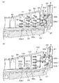
図7は、周方向リブによる水の流れを示し、(a)は本実施形態、(b)は比較例である。なお、白抜き矢印の大小は、循環水路Rを流れる洗濯水の流量の大小を示している。   FIG. 7 shows the flow of water by the circumferential rib, (a) is this embodiment, (b) is a comparative example. In addition, the magnitude of the white arrow indicates the magnitude of the flow rate of the wash water flowing through the circulation water channel R.

まず、図7(b)の比較例について説明すると、周方向リブ101,102は、裏羽根33の先端よりも内周側に位置している。また、周方向リブ101の先端101aは、入口27の高さ寸法Hの半分(二分の一)よりも下方に位置している。また、周方向リブ102の先端102aは、周方向リブ101の先端101aよりも底部22a側に位置している。   First, the comparative example of FIG. 7B will be described. The circumferential ribs 101 and 102 are located on the inner peripheral side with respect to the tip of the back blade 33. Further, the tip 101a of the circumferential rib 101 is positioned below half (1/2) of the height dimension H of the inlet 27. Further, the distal end 102 a of the circumferential rib 102 is positioned closer to the bottom 22 a than the distal end 101 a of the circumferential rib 101.

図7(b)の比較例では、洗濯水が隣り合う裏羽根33間に保持され、この状態で攪拌翼100が回転すると、洗濯水には外向きの遠心力が作用する。このとき、最も外側の円環リブ34と周方向リブ102との間に位置する空間Q10の下部の洗濯水は、白抜き矢印Y10で示すように、周方向リブ102の先端102aと底部22(底面22a1)との間を通って外周側に向けて押し出される。また、空間Q10の上部に位置する洗濯水は、周方向リブ102によって外周側への洗濯水の流れが制限される。   In the comparative example of FIG. 7B, the washing water is held between the adjacent back blades 33, and when the stirring blade 100 rotates in this state, an outward centrifugal force acts on the washing water. At this time, the wash water in the lower part of the space Q10 located between the outermost annular rib 34 and the circumferential rib 102 is, as indicated by the white arrow Y10, the tip 102a and the bottom 22 ( Extruded toward the outer peripheral side through the space between the bottom surface 22a1). Moreover, the flow of the wash water to the outer peripheral side is restricted by the circumferential rib 102 in the wash water located in the upper part of the space Q10.

また、周方向リブ101と周方向リブ102との間に位置する空間Q11の下部の洗濯水は、白抜き矢印Y11で示すように、周方向リブ101の先端101aと底部22a(底面22a1)との間を通って外周側に押し出される。また、空間Q11の上部に位置する洗濯水は、周方向リブ101によって外周側への洗濯水の流れが制限される。   Further, the washing water in the lower portion of the space Q11 located between the circumferential rib 101 and the circumferential rib 102 has a tip 101a and a bottom portion 22a (bottom surface 22a1) of the circumferential rib 101 as shown by a white arrow Y11. It is pushed out to the outer periphery side. Moreover, the flow of the wash water to the outer peripheral side is restricted by the circumferential rib 101 in the wash water located in the upper part of the space Q11.

また、周方向リブ101と垂下部3eとの間に位置する空間Q12に位置する洗濯水は、白抜き矢印Y12で示すように、洗濯水の一部が空間Q10,Q11からの洗濯水とともに入口27に向けて押し出される。また、洗濯水の残りは、攪拌翼100と循環流路部材24との間の隙間Sから洗濯槽2内に押し出される。   In addition, the washing water located in the space Q12 located between the circumferential rib 101 and the hanging portion 3e has a part of the washing water, together with the washing water from the spaces Q10 and Q11, as shown by the white arrow Y12. It is pushed toward 27. Further, the remaining washing water is pushed out into the washing tub 2 through the gap S between the stirring blade 100 and the circulation flow path member 24.

このような形状の攪拌翼100では、先端101a,102aが底板22の底面22a1に近い位置に形成された周方向リブ101,102によって外周側に押し出される洗濯水の流量が減少する。また、径方向外側(洗濯水が遠心力で押し出される側)に向けて隙間Sと入口27の双方に対向する空間Q12が形成されていることで、白抜き矢印Y13で示すように隙間Sから逃げる洗濯水の流量が増加し、白抜き矢印Y14で示すように入口27に流れる洗濯水の流量が減少する。   In the stirring blade 100 having such a shape, the flow rate of washing water pushed out to the outer peripheral side by the circumferential ribs 101 and 102 formed at positions where the tips 101a and 102a are close to the bottom surface 22a1 of the bottom plate 22 is reduced. Further, since the space Q12 facing both the gap S and the inlet 27 is formed toward the radially outer side (the side on which the washing water is pushed out by the centrifugal force), the gap S as shown by the white arrow Y13 is formed. The flow rate of the wash water that escapes increases, and the flow rate of the wash water flowing to the inlet 27 decreases as indicated by the white arrow Y14.

これに対して、図7(a)に示す本実施形態では、最も外側の円環リブ34と内周側リブ(周方向リブ)37との間に位置する空間Q1の下部の洗濯水は、白抜き矢印Y1で示すように、先端37aと底部22aとの間を通って外周側に向けて押し出される。また、空間Q1の上部の洗濯水は、白抜き矢印Y2で示すように、内周側リブ37によって斜め下向きの水流となって外周側に押し出される。   On the other hand, in the present embodiment shown in FIG. 7A, the wash water in the lower portion of the space Q1 located between the outermost annular rib 34 and the inner peripheral rib (circumferential rib) 37 is As indicated by a hollow arrow Y1, the sheet is pushed toward the outer peripheral side through the space between the tip 37a and the bottom 22a. Moreover, the washing water in the upper part of the space Q1 is pushed out to the outer peripheral side as an obliquely downward water flow by the inner peripheral side rib 37 as indicated by the white arrow Y2.

また、内周側リブ(周方向リブ)36と内周側リブ(周方向リブ)37との間に位置する空間Q2の下部の洗濯水は、白抜き矢印Y3で示すように、先端36aと底部22aとの間を通って外周側に押し出される。また、空間Q2の上部の洗濯水は、白抜き矢印Y4で示すように、内周側リブ36によって斜め下向きの水流となって外周側に押し出される。   In addition, the washing water in the lower part of the space Q2 located between the inner peripheral rib (circumferential rib) 36 and the inner peripheral rib (circumferential rib) 37 has a tip 36a as shown by a white arrow Y3. It is pushed to the outer peripheral side through the space between the bottom 22a. Further, as indicated by the white arrow Y4, the washing water in the upper portion of the space Q2 is pushed to the outer peripheral side by the inner peripheral side rib 36 as a water flow obliquely downward.

また、内周側リブ(周方向リブ)36と外周側リブ(周方向リブ)35との間に位置する空間Q3の下部の洗濯水は、白抜き矢印Y5で示すように、外周側に向けて押し出される。また、空間Q3の上部の洗濯水は、白抜き矢印Y6で示すように、斜め下向きの水流となって外周側に押し出される。そして、外周側リブ35の先端35aと底面22a1との間を通過した洗濯水は、白抜き矢印Y7で示すように、ほぼ全量が入口27に押し出される。   Also, the wash water in the lower part of the space Q3 located between the inner peripheral rib (circumferential rib) 36 and the outer peripheral rib (circumferential rib) 35 is directed toward the outer peripheral side as indicated by the white arrow Y5. Pushed out. Further, the washing water in the upper part of the space Q3 is pushed out to the outer peripheral side as an obliquely downward water flow as indicated by a hollow arrow Y6. And the washing water which passed between the front-end | tip 35a and the bottom face 22a1 of the outer peripheral side rib 35 is extruded by the inlet 27 substantially as shown by the white arrow Y7.

このように構成された本実施形態の洗濯機1では、内周側リブ36,37の先端36a,37aが外周側リブ35の先端35aよりも底面22a1から離れる位置に形成されているので、空間Q1,Q2の洗濯水を外周側に押し出すことができるとともに、下向きの水流を発生させることができ、空間Q1,Q2の洗濯水のほぼ全量を外周側の空間Q3に押し出すことができる。これにより、本実施形態では、攪拌翼3の剛性を低下させることなく、攪拌翼3の回転速度を上げ過ぎることなく、循環水量を従来よりも増加させることが可能になる。   In the washing machine 1 of the present embodiment configured as described above, the tips 36a, 37a of the inner peripheral ribs 36, 37 are formed at positions farther from the bottom surface 22a1 than the tips 35a of the outer peripheral ribs 35. The washing water of Q1 and Q2 can be pushed out to the outer peripheral side, a downward water flow can be generated, and almost all of the washing water in the spaces Q1 and Q2 can be pushed out to the outer space Q3. Thereby, in this embodiment, it becomes possible to increase the amount of circulating water more than before, without reducing the rigidity of the stirring blade 3, and without raising the rotational speed of the stirring blade 3 too much.

また、本実施形態では、外周側リブ35の先端35aが、入口27の高さ位置Hm(図5参照)よりも下方(底面22a1側に近い位置)に位置している。これにより、洗濯水を底部22a側に誘導することができ、外周側リブ35から外周側に越えた洗濯水を入口27に導入し易くなり、循環水路Rに導入される洗濯水の流量を増加させることができる。また、外周側リブ35の先端35aが、入口27の高さ位置Hm(図5参照)よりも下方に位置しているので、外周側リブ35から外周側に越えた洗濯水を入口27に直ちに導入でき、白抜き矢印Y8で示すように、隙間Sから逃げる洗濯水の流量を、図7(b)の場合よりも減少させることができる。   Further, in the present embodiment, the front end 35a of the outer peripheral rib 35 is located below the height position Hm (see FIG. 5) of the inlet 27 (position closer to the bottom surface 22a1 side). Accordingly, the wash water can be guided to the bottom 22a side, and it becomes easy to introduce the wash water beyond the outer peripheral side rib 35 to the outer peripheral side into the inlet 27, and the flow rate of the wash water introduced into the circulation channel R is increased. Can be made. Further, since the tip 35a of the outer peripheral side rib 35 is located below the height position Hm of the inlet 27 (see FIG. 5), the washing water that has passed from the outer peripheral side rib 35 to the outer peripheral side is immediately supplied to the inlet 27. As shown by the white arrow Y8, the flow rate of the washing water escaping from the gap S can be reduced as compared with the case of FIG.

ところで、本実施形態において、外周側リブ35を設けずに、内周側リブ(周方向リブ)36,37のみを設けた場合には、循環水路Rを流れる洗濯水の流量を図7(b)の場合よりも増加できるが、洗濯水が隙間Sから逃げる量も増加する。そこで、本実施形態では、周方向リブとして、内周側リブ36,37を設けるだけではなく、外周側リブ35を追加して設けることにより、循環水路Rを流れる洗濯水の流量を図7(b)の場合よりも増加させるようにしたものである。   By the way, in this embodiment, when only the inner peripheral side ribs (circumferential ribs) 36 and 37 are provided without providing the outer peripheral side rib 35, the flow rate of the washing water flowing through the circulation water channel R is shown in FIG. ), The amount of washing water escaping from the gap S also increases. Therefore, in the present embodiment, not only the inner peripheral ribs 36 and 37 are provided as the circumferential ribs, but the outer peripheral ribs 35 are additionally provided, whereby the flow rate of the washing water flowing through the circulation channel R is shown in FIG. It is made to increase rather than the case of b).

また、本実施形態では、外周側リブ35が裏羽根33の外周端側(外周端)に位置している。これにより、洗濯水が隙間Sから逃げる量を減少させることができるとともに、裏羽根33の撓み変形を抑制することができるので、攪拌翼3の剛性を高めることができる。   In the present embodiment, the outer peripheral rib 35 is located on the outer peripheral end side (outer peripheral end) of the back blade 33. Thereby, while being able to reduce the quantity which washing water escapes from crevice S, since bending deformation of back blade 33 can be controlled, the rigidity of stirring blade 3 can be raised.

また、本実施形態では、内周側リブ36,37の先端36a,37aが、外周側に向かうにつれて底部22aに近づく側に位置している。これにより、洗濯水が外周側に向かうにつれて、洗濯水を下方に向けて誘導し易くなるので、より多くの洗濯水を入口27に導入し易くなる。   Moreover, in this embodiment, the front-end | tips 36a and 37a of the inner peripheral side ribs 36 and 37 are located in the side which approaches the bottom part 22a as it goes to an outer peripheral side. As a result, it becomes easier to guide the washing water downward as the washing water moves toward the outer peripheral side, so that it becomes easier to introduce more washing water into the inlet 27.

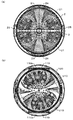
図8は、シャワー拡散のイメージ図を示し、(a)は本実施形態、(b)は比較例である。なお、(a)および(b)のいずれも、バランスリング23の図示を省略している。   FIG. 8 shows an image of shower diffusion, (a) is the present embodiment, and (b) is a comparative example. Note that in both (a) and (b), the balance ring 23 is not shown.

図8(b)に示す比較例としての洗濯槽120は、循環流路部材110の上端が循環流路部材24のように上方に開放する吐出口31が形成されたものではなく、洗濯槽120の内側に向けて上板110aを備えたものである。この洗濯槽120では、図7(b)の構成において、洗濯水が吐出されると、図8(b)の斜線で示す領域U10で示すように、洗濯水の拡散角度が制限された状態で吐出される。   The washing tub 120 as a comparative example shown in FIG. 8B does not have a discharge port 31 that opens upward at the upper end of the circulation channel member 110 like the circulation channel member 24. An upper plate 110a is provided toward the inside. In the washing tub 120, when the washing water is discharged in the configuration of FIG. 7B, the washing water diffusion angle is limited as indicated by the hatched region U10 in FIG. 8B. Discharged.

これに対して、図8(a)に示す本実施形態の洗濯槽2は、外周側リブ35と内周側リブ36,37とによって循環水路Rを流れる洗濯槽2の循環流量を増加させたことで、図8(a)の斜線で示す領域U1で示すように、循環流路部材24の吐出口31から吐出された洗濯水の拡散角度を図8(b)よりも拡大させることができる。これにより、洗い工程やすすぎ工程において、洗濯水を洗濯物の全体に散布することができる。   On the other hand, in the washing tub 2 of the present embodiment shown in FIG. 8A, the circulation flow rate of the washing tub 2 flowing through the circulation water channel R is increased by the outer peripheral side rib 35 and the inner peripheral side ribs 36 and 37. Thus, as shown by a region U1 indicated by oblique lines in FIG. 8A, the diffusion angle of the washing water discharged from the discharge port 31 of the circulation flow path member 24 can be made larger than that in FIG. 8B. . Thereby, in the washing process or the rinsing process, the washing water can be sprayed over the entire laundry.

また、本実施形態では、循環水路Rが上方に向けて開口する吐出口31を備え、この吐出口31が洗濯槽2に設けられたバランスリング23の下面23aと対向して配置されている。これにより、図8(b)の循環流路部材110の上板110aを不要にできるので、洗濯水をバランスリング23の下面23aに直接当てることができ、洗濯水の拡散角度を拡大できる。   Moreover, in this embodiment, the circulation water channel R is provided with the discharge port 31 which opens upwards, and this discharge port 31 is arrange | positioned facing the lower surface 23a of the balance ring 23 provided in the washing tub 2. As shown in FIG. Accordingly, the upper plate 110a of the circulation channel member 110 in FIG. 8B can be made unnecessary, so that the washing water can be directly applied to the lower surface 23a of the balance ring 23, and the diffusion angle of the washing water can be expanded.

また、本実施形態では、循環水量が増加できることで、糸くず捕集部材26で捕集される異物(糸くず)の捕集率も向上できる。   Moreover, in this embodiment, the collection rate of the foreign material (lint waste) collected by the waste thread collection member 26 can also be improved because the amount of circulating water can be increased.

なお、本発明は前記した実施形態に限定されるものではなく、本発明の範囲を変更しない範囲において種々変更することができる。前記した実施形態では、4つの循環流路部材24,25を設けた場合を例に挙げて説明したが、1つ、2つ、3つ、5つ以上の循環流路部材を備えたものであってもよい。   In addition, this invention is not limited to above-described embodiment, In the range which does not change the range of this invention, it can change variously. In the above-described embodiment, the case where the four circulation channel members 24 and 25 are provided has been described as an example. However, one, two, three, five or more circulation channel members are provided. There may be.

また、本実施形態では、3枚の周方向リブ(外周側リブ35、内周側リブ36,37)を設けた場合を例に挙げて説明したが、3枚に限定されるものではなく、例えば、2枚の周方向リブ(外周側リブ35、内周側リブ)であってもよく、4枚以上の周方向リブ(外周側リブ35、3つの内周側リブ)であってもよく、攪拌翼3の剛性を損なわない範囲において適宜変更できる。   Further, in the present embodiment, the case where three circumferential ribs (outer peripheral side rib 35, inner peripheral side ribs 36, 37) are provided is described as an example, but is not limited to three. For example, it may be two circumferential ribs (outer peripheral rib 35, inner peripheral rib) or four or more circumferential ribs (outer peripheral rib 35, three inner peripheral ribs). As long as the rigidity of the stirring blade 3 is not impaired, it can be changed as appropriate.

また、本実施形態では、内周側リブ36の先端36aが内周側リブ37の先端37aよりも下方に位置する場合を例に挙げて説明したが、先端36a,37aが互いに同じ長さの内周側リブ36,37であってもよい。   In this embodiment, the case where the tip 36a of the inner peripheral rib 36 is positioned below the tip 37a of the inner rib 37 has been described as an example. However, the tips 36a and 37a have the same length. The inner peripheral side ribs 36 and 37 may be sufficient.

また、本実施形態では、攪拌翼3の形状が周方向にそって波打つ形状のものを例に挙げて説明したが、このような形状のものに限定されるものではなく、周方向に沿って一定の形状を有する攪拌翼にも適用できる。この場合にも、前記した外周側リブ35および内周側リブ36,37を設けることにより、前記した本実施形態と同様の効果を得ることができる。   Further, in the present embodiment, the shape of the stirring blade 3 is described as an example in which the shape of the stirring blade 3 undulates along the circumferential direction. However, the shape of the stirring blade 3 is not limited to such a shape, and is along the circumferential direction. The present invention can also be applied to a stirring blade having a certain shape. Also in this case, by providing the outer peripheral side rib 35 and the inner peripheral side ribs 36 and 37, it is possible to obtain the same effect as the above-described embodiment.

次に本発明の別の実施例を説明する。図9は、本実施形態の操作パネル200の概略図を示したものである。操作パネル200は、大きく操作パネル200の上部にある表示部201と、下部にある操作部202に分けられている。   Next, another embodiment of the present invention will be described. FIG. 9 shows a schematic diagram of the operation panel 200 of the present embodiment. The operation panel 200 is roughly divided into a display unit 201 at the top of the operation panel 200 and an operation unit 202 at the bottom.

操作部202には、電源を入切するための電源ボタン203と、運転を開始もしくは一時停止させるためのスタートスイッチ204と、洗濯運転コースを設定するための洗濯コースボタン205と、洗濯運転の詳細設定を行うための設定ボタン206とを備える。表示部201には、洗濯運転の対象となるコースを表示させるためのコース表示欄207とを備えている。   The operation unit 202 includes a power button 203 for turning on / off the power, a start switch 204 for starting or pausing operation, a washing course button 205 for setting a washing operation course, and details of the washing operation. A setting button 206 for performing setting. The display unit 201 includes a course display field 207 for displaying a course to be subjected to a washing operation.

洗濯運転時には、電源ボタン203を押下後に、洗濯コースボタン205を押下するごとに、コース表示欄207の点灯位置が切り替わり、運転する洗濯コース(標準コース、ドライコース、デリケートコースなど)を点灯させ、スタートスイッチ204を押下することで選択された洗濯コースの運転を開始する。   During the washing operation, every time the washing course button 205 is pressed after the power button 203 is pressed, the lighting position of the course display column 207 is switched, and the washing course to be driven (standard course, dry course, delicate course, etc.) is turned on. Pressing the start switch 204 starts the operation of the selected laundry course.

図10〜図12は、各洗濯コースの行程動作の詳細を示すフローチャートである。   10 to 12 are flowcharts showing details of the stroke operation of each washing course.

図10は標準コースに係る洗浄方式の行程動作を示す。図11はドライコースに係る洗浄方式の行程動作を示す。図12は、本実施例の特徴であるデリケートコースに係る洗浄方式の行程動作を示す。   FIG. 10 shows the stroke operation of the cleaning method according to the standard course. FIG. 11 shows the stroke operation of the cleaning method related to the dry course. FIG. 12 shows the stroke operation of the cleaning system related to the delicate course, which is a feature of this embodiment.

コントロールユニット19は、電源ボタン203が押されて電源が投入されると起動し、選択されたコースに応じて、図10〜図12に示す洗濯の基本的な制御処理プログラムを実行する。   The control unit 19 is activated when the power button 203 is pressed and the power is turned on, and executes the basic control processing program for washing shown in FIGS. 10 to 12 according to the selected course.

まず、図10の標準コースの係る洗浄方式の行程動作を説明する。   First, the process operation of the cleaning method according to the standard course of FIG. 10 will be described.

ステップS301において、コントロールユニット19は、洗濯機1の状態確認および初期設定を行う。   In step S <b> 301, the control unit 19 performs state confirmation and initial setting of the washing machine 1.

ステップS302において、コントロールユニット19は、洗濯コースボタン205からの入力指示にしたがって洗濯コースを設定する。入力指示がない状態では、標準の洗濯コースまたは前回実施の洗濯コースを自動的に設定する。   In step S <b> 302, the control unit 19 sets a washing course according to an input instruction from the washing course button 205. When there is no input instruction, the standard washing course or the previous washing course is automatically set.

ステップS303において、コントロールユニット19は、スタートスイッチ204からのスタートスイッチ信号の入力を監視する。コントロールユニット19は、スタートスイッチ信号の入力が無いと判定した場合には、ステップS303の処理を繰り返し、スタートスイッチ信号の入力が有りと判定した場合には、ステップS304に進む。   In step S <b> 303, the control unit 19 monitors the input of the start switch signal from the start switch 204. If the control unit 19 determines that there is no input of the start switch signal, it repeats the process of step S303, and if it determines that there is an input of the start switch signal, it proceeds to step S304.

ステップS304において、コントロールユニット19は、洗剤量検出処理を実行する。この洗剤量検出処理は、洗い水を給水する前の洗濯物が乾布状態において、洗濯槽2を静止させた状態で攪拌翼3を一方向に回転させたときに、該攪拌翼3に作用する回転負荷量に基づいて洗濯物の布量を検出することにより行う。コントロールユニット19は、検出した布量に基づいて洗剤の適量(洗剤量)を求める。洗剤量は、予め設定した布量と洗剤量の対照テーブルを参照することによって求める。   In step S304, the control unit 19 executes a detergent amount detection process. This detergent amount detection processing is applied to the stirring blade 3 when the laundry before supplying the washing water is in a dry cloth state and the stirring blade 3 is rotated in one direction while the washing tub 2 is stationary. This is done by detecting the amount of laundry on the basis of the rotational load. The control unit 19 obtains an appropriate amount of detergent (detergent amount) based on the detected cloth amount. The detergent amount is determined by referring to a preset table of cloth amount and detergent amount.

また、洗濯水量は、布量が所定の布量の範囲(適量)内のときには、例えば攪拌翼3を越えない水位を維持して外槽7の底部に溜まるように洗濯水量(水位h1)を設定する。   In addition, when the amount of washing water is within a predetermined range (appropriate amount) of the amount of cloth, for example, the amount of washing water (water level h1) is set so that the water level does not exceed the stirring blade 3 and is accumulated at the bottom of the outer tub 7. Set.

また、コントロールユニット19は、検出結果(布量)に基づいて洗濯時間を求めて設定する。布量検出が行われない場合には、標準の洗濯時間を設定する。   Further, the control unit 19 obtains and sets the washing time based on the detection result (cloth amount). When the amount of cloth is not detected, a standard washing time is set.

ステップS305において、コントロールユニット19は、求めた洗剤量を操作パネル200の表示部201に表示する。   In step S <b> 305, the control unit 19 displays the obtained detergent amount on the display unit 201 of the operation panel 200.

ステップS306において、コントロールユニット19は、洗剤給水電磁弁(不図示)を開き、洗剤・仕上げ剤容器(不図示)の洗剤投入室に対して洗剤給水を実行する。なお、使用者は、洗剤給水前に、表示された量の粉末洗剤を洗剤・仕上げ剤容器(不図示)の洗剤投入室に投入した後、蓋体9bを閉じるように操作する。洗剤給水が流れている洗剤投入室に投入された粉末洗剤は、洗剤給水の水と共に洗剤・仕上げ剤容器を通り外槽7の底部に落下する。   In step S306, the control unit 19 opens the detergent water supply electromagnetic valve (not shown), and executes the detergent water supply to the detergent charging chamber of the detergent / finishing agent container (not shown). The user operates to close the lid 9b after putting the indicated amount of powder detergent into the detergent charging chamber of the detergent / finishing agent container (not shown) before supplying the detergent. The powder detergent put into the detergent charging chamber in which the detergent water is flowing passes through the detergent / finishing agent container and falls to the bottom of the outer tub 7 together with the detergent water.

ステップS307において、コントロールユニット19は、洗剤溶かし水位まで給水後、洗剤給水を停止する。この実施形態では、洗剤給水量を洗濯量(布量)に関わらず、例えば、約10リットルに設定した。この水量は、この後の洗剤溶かし(ステップS309)で洗濯槽2を回転させたときに、洗濯槽2の底で給水した水と洗剤を攪拌するのに十分な水量で、かつ、水面が攪拌翼3の下面の高さより低くなる(洗濯物が洗剤溶かし前に濡れない)ように設定される。この設定が終了すると洗剤の給水を停止する(ステップS308)。   In step S307, the control unit 19 stops the detergent water supply after supplying the detergent to the dissolved water level. In this embodiment, the detergent water supply amount is set to about 10 liters, for example, regardless of the washing amount (cloth amount). This amount of water is sufficient to agitate the water supplied at the bottom of the washing tub 2 and the detergent when the washing tub 2 is rotated in the subsequent detergent dissolution (step S309), and the water surface is agitated. It is set to be lower than the height of the lower surface of the wing 3 (the laundry does not get wet before the detergent is dissolved). When this setting is completed, the detergent water supply is stopped (step S308).

ステップS309において、コントロールユニット19は、洗濯槽2と攪拌翼3を一体的に一方向に緩速回転(例えば、約毎分70回転)させることによって、該洗濯槽2の底面で外槽7の底部に投入された洗剤溶かし水と粉末洗剤を攪拌して高洗剤濃度の洗い水を生成する洗剤溶かしを実行する。洗剤溶かしの時間は、例えば1分間に設定される。低温(低水温)、溶けにくい粉末洗剤の条件でも約90%の溶解率となる。生成した洗い水の洗剤濃度は、標準濃度の約7倍である。ここで、標準濃度は、例えば粉末洗剤量20グラム/洗い水量30リットルの割合である。   In step S309, the control unit 19 slowly rotates the washing tub 2 and the stirring blade 3 integrally in one direction (for example, about 70 rotations per minute), so that the outer tub 7 Detergent dissolving is performed by stirring the detergent-dissolved water and the powder detergent supplied to the bottom to produce wash water with a high detergent concentration. The time for dissolving the detergent is set to 1 minute, for example. The dissolution rate is about 90% even under conditions of low temperature (low water temperature) and difficult to dissolve powder detergent. The detergent concentration of the produced wash water is about 7 times the standard concentration. Here, the standard concentration is, for example, a ratio of 20 grams of powder detergent / 30 liters of washing water.

ステップS310において、前行程を実行する。コントロールユニット19は、前記と同様な方法で布量検出を実行して、設定水位になるまで水道水(清水)の給水と高濃度撹拌を繰り返す。高濃度撹拌は、生成された高洗剤濃度の洗剤を撹拌して洗濯物に行き届かせるように、洗濯槽2を固定した状態(攪拌モード)で攪拌翼3を回転させる。   In step S310, the previous process is executed. The control unit 19 executes cloth amount detection in the same manner as described above, and repeats tap water (fresh water) supply and high-concentration agitation until the set water level is reached. In the high-concentration stirring, the stirring blade 3 is rotated in a state where the washing tub 2 is fixed (stirring mode) so as to stir the generated detergent having a high detergent concentration and reach the laundry.

そして、ステップS311において、洗いの設定水位で、洗濯槽2を固定した状態(攪拌モード)で攪拌翼3を回転させて本洗いを実行する。また、コントロールユニット19は、攪拌翼3を正逆回転させる約1分間の均一化攪拌を実行する。   In step S311, the main washing is performed by rotating the stirring blade 3 while the washing tub 2 is fixed (stirring mode) at the set water level for washing. Further, the control unit 19 performs uniform stirring for about 1 minute by rotating the stirring blade 3 forward and backward.

その後、すすぎ行程を経て(ステップS312、ステップS313)、最終脱水行程(Sステップ314)に移行する。   Then, after passing through a rinsing process (steps S312 and S313), the process proceeds to a final dehydration process (Sstep 314).

このように、本洗いでの水流パターンについて、標準コースにおいては洗濯槽2を固定した状態で、攪拌翼3を左右反転回転させることで、洗濯槽2内に強い水流を発生させるとともに、循環水路Rへの洗濯水の流入量を増加させて、高い洗浄力を実現している。   As described above, with respect to the water flow pattern in the main washing, in the standard course, the washing tub 2 is fixed and the stirring blade 3 is rotated in the left-right direction to generate a strong water flow in the washing tub 2 and the circulation channel. The amount of washing water flowing into R is increased to achieve high detergency.

次に図11を用いて、ドライコースの場合を説明するが、図10の標準コースの場合と異なる部分のみを説明する。   Next, the case of the dry course will be described with reference to FIG. 11, but only the portions different from the case of the standard course of FIG. 10 will be described.

標準コースの動作に対して、ドライコースにおいては、図10のステップS304の「洗剤量検出」を廃止している。また、ステップS310の前行程での「布量検出」や「高濃度攪拌」等の水量の低いときの攪拌動作を廃止している(ステップS409)。   In contrast to the operation of the standard course, the “detergent detection” in step S304 in FIG. 10 is abolished in the dry course. Also, the stirring operation when the amount of water is low, such as “cloth amount detection” and “high concentration stirring” in the previous step of step S310 is abolished (step S409).

また、ドライコースにおいては、ステップS410の本洗い行程において、洗濯槽2と攪拌翼3を一体的に同一方向に回転させるモードで洗いを実行する。これにより、洗濯物と攪拌翼3とが擦れることを防ぎ、衣類の布傷みや布絡み、縮み、型くずれを抑えた洗浄を可能としている。   In the dry course, washing is performed in a mode in which the washing tub 2 and the stirring blade 3 are integrally rotated in the same direction in the main washing process of step S410. As a result, rubbing between the laundry and the stirring blade 3 is prevented, and washing that prevents cloth damage, cloth entanglement, shrinkage, and deformation of the garment is possible.

次に図12を用いて、本実施例の特徴であるデリケートコースの場合を説明するが、図10の標準コースの場合と異なる部分のみを説明する。   Next, the case of the delicate course, which is a feature of the present embodiment, will be described with reference to FIG. 12, but only the portions different from the case of the standard course of FIG.

標準コースの動作に対して、デリケートコースにおいては、図10のステップS304の「洗剤量検出」を廃止している。また、ステップS310の前行程での「布量検出」や「高濃度攪拌」等の水量の低いときの攪拌動作を廃止している(ステップS509)。   In contrast to the operation of the standard course, “detergent detection” in step S304 in FIG. 10 is abolished in the delicate course. Also, the stirring operation when the amount of water is low, such as “cloth amount detection” and “high concentration stirring” in the previous step of step S310 is abolished (step S509).

また、デリケートコースにおいては、ステップS510の本洗い行程において、洗濯槽2を静止させない状態(洗濯槽2を固定しないが、駆動装置6で直接回転できない状態)で攪拌翼3を正逆両方向に回転させる中立モードで、攪拌翼3を回転させて本洗いを実行する。中立モードでは、攪拌翼3が回転を始めると、その反力で洗濯槽2は攪拌翼3の回転方向と逆方向に回転し、その後停止し攪拌翼3と同じ方向に回転する。また、後述するが標準コースの水位よりも高い水位となっている。   In the delicate course, the stirring blade 3 is rotated in both forward and reverse directions in the state where the washing tub 2 is not stationary (the washing tub 2 is not fixed but cannot be directly rotated by the driving device 6) in the main washing process of step S510. In the neutral mode, the main washing is performed by rotating the stirring blade 3. In the neutral mode, when the stirring blade 3 starts to rotate, the washing tub 2 rotates in the direction opposite to the rotation direction of the stirring blade 3 by the reaction force, and then stops and rotates in the same direction as the stirring blade 3. As will be described later, the water level is higher than that of the standard course.

上記のように、「洗剤量検出」「布量検出」「高濃度攪拌」などの水位が低いときの攪拌動作をドライコース同様に廃止することで、洗濯物と攪拌翼3とが擦れることを防ぎ、衣類の布傷みや布絡み、縮み、型くずれを抑えた洗浄を可能としている。   As described above, the agitation operation when the water level is low such as “detergent amount detection”, “cloth amount detection”, “high concentration agitation”, etc., is abolished in the same manner as the dry course, so that the laundry and the agitating blade 3 are rubbed. It prevents washing and prevents cloth damage, fabric entanglement, shrinkage, and shape loss.

また、本洗いの行程では、洗濯槽2に十分な洗濯水が溜まり、標準モードよりも高い水位となった後、洗濯槽2を固定せずに、中立モードで、攪拌翼3を回転させることで、洗濯物と洗濯槽2および攪拌翼3とが擦れることを抑制し、衣類の布傷みや布絡み、縮み、型くずれを抑えつつも、攪拌翼3と洗濯槽2との相対回転で発生する水流により高い洗浄力での洗浄を可能としている。   In the main washing process, after sufficient washing water is accumulated in the washing tub 2 and the water level becomes higher than that in the standard mode, the stirring wing 3 is rotated in the neutral mode without fixing the washing tub 2. Thus, the rubbing of the laundry with the washing tub 2 and the stirring wing 3 is suppressed, and the garment is caused by the relative rotation of the stirring wing 3 and the washing tub 2 while suppressing cloth damage, cloth entanglement, shrinkage, and deformation of the clothing. Washing with high detergency is possible by water flow.

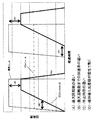
図13は、上記本洗いでの攪拌動作を標準コース、ドライコース、デリケートコースで比較した図であり、経過時間に対する攪拌翼3の回転数の変化を示している。なお、このとき、洗濯物の負荷量は各コースで同一であるとする。   FIG. 13 is a diagram comparing the stirring operation in the main washing in the standard course, the dry course, and the delicate course, and shows the change in the rotation speed of the stirring blade 3 with respect to the elapsed time. At this time, it is assumed that the load of the laundry is the same in each course.

記号(A)は、標準コースとデリケートコースの攪拌翼3の最大回転数の違いを示しており、デリケートコースでは標準コースよりも低い回転数で攪拌翼3を回転させる。これにより、強い水流が発生せず、洗濯物と洗濯槽2および攪拌翼3とが擦れることを防ぎ、衣類の布傷みや布絡み、縮み、型くずれを抑えつつも、高い洗浄力での洗浄を可能としている。   Symbol (A) indicates the difference in the maximum number of rotations of the stirring blade 3 between the standard course and the delicate course. In the delicate course, the stirring blade 3 is rotated at a speed lower than that of the standard course. As a result, strong water flow is not generated, and the laundry, the washing tub 2 and the stirring blade 3 are prevented from rubbing and washing with high detergency is performed while suppressing cloth damage, cloth entanglement, shrinkage, and deformation of the clothing. It is possible.

記号(B)は、標準コースとデリケートコースの最大回転数到達までの攪拌翼3の回転数の加速率の違いを示しており、デリケートコースでは標準コースよりも低い加速率で、攪拌翼3の回転数を上昇させている。これにより、攪拌翼3の回転開始時に洗濯物と攪拌翼3とが擦れることを防ぎ、衣類の布傷みや布絡み、縮み、型くずれを抑えつつも、高い洗浄力での洗浄を可能としている。また、標準コースでは攪拌翼3の回転数の加速率が高いため、洗濯槽2内で上下方向と回転方向が合成された強い水流が発生し、洗濯物と攪拌翼3が直接接触し高い洗浄力を実現している。これに対し、デリケートコースでは、攪拌翼3の回転数をゆっくり上昇しているため、洗濯槽2内で回転方向の渦巻き状の水流のみが発生するため、洗濯物と攪拌翼3の直接の接触が発生しない。   Symbol (B) indicates the difference in the acceleration rate of the rotation speed of the stirring blade 3 until the maximum rotation speed of the standard course and the delicate course is reached. The delicate course has a lower acceleration rate than that of the standard course. The rotational speed is increased. As a result, the laundry and the stirring blade 3 are prevented from rubbing at the start of rotation of the stirring blade 3, and washing with high detergency is possible while suppressing cloth damage, cloth entanglement, shrinkage, and shape loss of clothing. Moreover, since the acceleration rate of the rotation speed of the stirring blade 3 is high in the standard course, a strong water flow in which the vertical direction and the rotation direction are combined in the washing tub 2 is generated, and the laundry and the stirring blade 3 are in direct contact with each other to perform high cleaning. The power is realized. On the other hand, in the delicate course, since the rotational speed of the stirring blade 3 is slowly increased, only a swirling water flow in the rotational direction is generated in the washing tub 2, so that the laundry and the stirring blade 3 are in direct contact with each other. Does not occur.

記号(C)は、標準コースとデリケートコースの休止時間の違いを示しており、デリケートコースでは標準コースよりも長い休止時間を設けることで、攪拌翼3の回転が停止した後、洗濯槽2内の水流が弱くなった状態で攪拌翼3を反対方向に回転させるため、強い水流が発生せず、衣類の布傷みや布絡み、縮み、型くずれを抑えた洗浄を可能としている。   The symbol (C) indicates the difference between the rest time of the standard course and the delicate course. In the delicate course, a longer rest time than that of the standard course is provided so that the rotation of the stirring blade 3 is stopped, and then the inside of the washing tub 2 Since the stirring blade 3 is rotated in the opposite direction in a state where the water flow is weakened, no strong water flow is generated, and it is possible to perform washing while suppressing cloth damage, cloth entanglement, shrinkage, and deformation of the clothing.

記号(D)は、標準コースとデリケートコースの攪拌停止時の攪拌翼3の回転の違いを示しており、標準コースでは攪拌翼3の回転を急に止めているのに対し、デリケートコースでは、攪拌翼3の回転をゆっくり止めている(減速率が低い)。こうすることで、洗濯槽2内の水流が急激に変化しないため、衣類の布傷みや布絡み、縮み、型くずれを抑えつつも、高い洗浄力での洗浄を可能としている。さらに、標準コースでは洗濯槽2が固定されているため、攪拌翼3の攪拌後は衣類だけが洗濯槽2内の水流とともに動く。一方、デリケートコースでは洗濯槽2が固定されていないため、攪拌翼3の攪拌後に衣類だけでなく、洗濯槽2も同一方向へ回転するため、洗濯物と洗濯槽2との擦れが生じにくく、衣類の布傷みや布絡み、縮み、型くずれを抑えることができる。   The symbol (D) indicates the difference in rotation of the stirring blade 3 when the stirring of the standard course and the delicate course is stopped. In the standard course, the rotation of the stirring blade 3 is suddenly stopped, whereas in the delicate course, The rotation of the stirring blade 3 is slowly stopped (the deceleration rate is low). By doing so, since the water flow in the washing tub 2 does not change abruptly, it is possible to perform washing with high detergency while suppressing cloth damage, entanglement, shrinkage, and deformation of the clothing. Furthermore, since the washing tub 2 is fixed in the standard course, only the clothes move with the water flow in the washing tub 2 after the stirring blade 3 is stirred. On the other hand, since the washing tub 2 is not fixed in the delicate course, not only the clothes but also the washing tub 2 rotates in the same direction after the stirring blade 3 is stirred, so that rubbing between the laundry and the washing tub 2 hardly occurs. Cloth damage, cloth entanglement, shrinkage, and deformation of clothing can be suppressed.

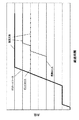
図14は、上記本洗いでの洗濯槽2内の水位の変化を標準コース、ドライコース、デリケートコースで比較した図である。図14において、破線が標準コースの場合、実線がデリケートコースの場合、一点鎖線がドライコースの場合を示している。なお、このとき、洗濯物の負荷量は各コースで同一であるとする。   FIG. 14 is a diagram comparing the change in the water level in the washing tub 2 during the main washing in the standard course, the dry course, and the delicate course. In FIG. 14, the broken line is a standard course, the solid line is a delicate course, and the alternate long and short dash line is a dry course. At this time, it is assumed that the load of the laundry is the same in each course.

図14で示す通り、デリケートコースの洗いの設定水位は標準コース及びドライコースの洗いの設定水位よりも高い水位としており、また、洗剤溶かし水位以降は一気に設定水位まで給水している。これにより、本洗いで攪拌翼3を回転した場合に、攪拌翼3と洗濯物との距離が十分あるため、攪拌翼3と洗濯物の接触を抑制することが可能となる。また、上述のように、デリケートコースの前行程では、布量検出、高濃度撹拌を行わないため、本洗い(設定水位で洗い)を行うまでの時間が標準コースの場合に比べて短い。   As shown in FIG. 14, the set water level for washing the delicate course is higher than the set water level for washing the standard course and the dry course, and after the detergent is dissolved, the water is supplied to the set water level all at once. As a result, when the stirring blade 3 is rotated during main washing, the distance between the stirring blade 3 and the laundry is sufficient, so that the contact between the stirring blade 3 and the laundry can be suppressed. Further, as described above, since the cloth amount is not detected and the high-concentration stirring is not performed in the previous process of the delicate course, the time until the main washing (washing at the set water level) is shorter than that in the standard course.

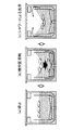
図15は、攪拌翼3と動きと衣類の動きとの関係を示す図である。図15(a)に示すように、例えば、ウール素材など衣類は、洗濯中においても、攪拌翼3が停止している場合は、衣類が水面に浮かんでしまうため、充分に含水せず、洗浄力が確保しにくい。本実施例では、攪拌翼3を回転させることにより、洗濯槽2内の洗濯水は渦巻き状の水流を起こし、水面はすり鉢状になる。この水流により、洗濯槽2内の衣類を下方に引き込み、衣類に含水させることが可能となる(図15(b))。さらに、攪拌翼3の回転に伴い、シャワーが洗濯槽の上方から散布されるため、更に衣類の含水量が多くなる。このようにして、攪拌翼3の回転に伴う循環シャワーを利用して、ウール素材などの水面に浮かんでしまいやすい衣類を対象とする場合でも、洗浄力を確保することが出来る。   FIG. 15 is a diagram illustrating the relationship among the stirring blade 3, movement, and movement of clothes. As shown in FIG. 15 (a), for example, clothes such as a wool material are not sufficiently hydrated and washed because the clothes float on the water surface when the stirring blade 3 is stopped even during washing. Power is difficult to secure. In the present embodiment, by rotating the stirring blade 3, the washing water in the washing tub 2 causes a spiral water flow, and the water surface becomes a mortar shape. With this water flow, the clothes in the washing tub 2 can be drawn downward to allow the clothes to contain water (FIG. 15B). Furthermore, since the shower is sprinkled from above the washing tub with the rotation of the stirring blade 3, the moisture content of the clothes further increases. In this way, even when a clothing that tends to float on the water surface, such as a wool material, is used by utilizing a circulating shower associated with the rotation of the stirring blade 3, the cleaning power can be ensured.

上述のデリケートコースでは、中立モードで洗いを実行する例を説明したが、本発明はこれに限られず、洗濯槽2を固定した状態で攪拌翼3を回転させる攪拌モードでデリケートコースのおける洗いを実行してもよい。この際、水位を高くしたり、攪拌翼3の回転の加速率や攪拌翼3の回転数を低くしたりすることで、衣類の布傷みや布絡み、縮み、型くずれを抑えて、高い洗浄力での洗浄が可能となる。   In the above-described delicate course, the example in which the washing is performed in the neutral mode has been described. However, the present invention is not limited thereto, and the washing of the delicate course can be performed in the stirring mode in which the stirring blade 3 is rotated while the washing tub 2 is fixed. May be executed. At this time, by increasing the water level or decreasing the rotation rate of the stirring blade 3 or the rotation speed of the stirring blade 3, the cloth can be prevented from being damaged, entangled, shrunk, or deformed. Cleaning with is possible.

また、上述のデリケートコースでは、標準コースに比べて高い設定水位で洗う例を説明したが、設定水位を標準コースと同じにして、攪拌翼3の回転の加速率及び/又は攪拌翼3の回転数を標準コースに比べて低くしてもよい。これにより、衣類の布傷みや布絡み、縮み、型くずれを抑えて、高い洗浄力での洗浄が可能となる。   Moreover, in the above-described delicate course, the example of washing at a set water level higher than that of the standard course has been described. However, the set water level is the same as that of the standard course, and the rotation rate of the stirring blade 3 and / or the rotation of the stirring blade 3 is increased. The number may be lower than the standard course. As a result, the cloth can be washed with a high detergency while suppressing garment damage, cloth entanglement, shrinkage, and shape loss.

1 洗濯機
2 洗濯槽
3 攪拌翼
21 胴板
22 底板
22a 底部(底)
22a1 底面
22b 側部
23 バランスリング
23 バランスリングの下面
24,25 循環流路部材
24b1 つば部
27 入口
31 吐出口
33 裏羽根(径方向リブ)
35 外周側リブ(周方向リブ)
35a 外周側リブの先端
36,37 内周側リブ(周方向リブ)
36a,37a 内周側リブの先端
D 径方向
Hm 入口の高さ位置
R 循環水路
W 周方向
DESCRIPTION OF SYMBOLS 1 Washing machine 2 Washing tub 3 Stirring blade 21 Trunk plate 22 Bottom plate 22a Bottom (bottom)
22a1 bottom 22b side 23 balance ring 23 bottom surface 24, 25 circulation ring member 24b1 collar 27 inlet 31 discharge port 33 back blade (radial rib)
35 Outer peripheral side rib (circumferential rib)
35a Tip of outer rib 36, 37 Inner rib (circumferential rib)
36a, 37a End of inner peripheral rib D Radial direction Hm Inlet height position R Circulation channel W Circumferential direction

Claims (5)

洗濯槽と、
前記洗濯槽の底に設けられる攪拌翼と、
前記洗濯槽と前記攪拌翼を回転駆動させる駆動装置と、
前記洗濯槽に給水する給水手段と、を備える洗濯機において、
標準コースである第1の洗濯コースと、前記第1の洗濯コースとは異なる第2の洗濯コースと、を有し、
前記第1の洗濯コースが選択された場合、前記給水手段により前記洗濯槽に第1の設定水位まで給水した状態で、前記攪拌翼を回転させて洗いを実行し、
前記第2の洗濯コースが選択された場合、前記給水手段により前記洗濯槽に前記第1の設定水位よりも高い第2の設定水位まで給水した状態で、前記攪拌翼を回転させて洗いを実行する、ことを特徴とする洗濯機。
A washing tub,
A stirring blade provided at the bottom of the washing tub;
A driving device for rotationally driving the washing tub and the stirring blade;
In a washing machine comprising water supply means for supplying water to the washing tub,
A first washing course that is a standard course, and a second washing course that is different from the first washing course,
When the first washing course is selected, in a state where water is supplied to the washing tub to the first set water level by the water supply means, washing is performed by rotating the stirring blade,
When the second washing course is selected, washing is performed by rotating the stirring blade while the water supply means supplies the washing tub to a second set water level higher than the first set water level. A washing machine characterized by that.
請求項1に記載の洗濯機であって、
前記第1の洗濯コースが選択された場合、前記駆動装置は、前記洗濯槽の回転を固定する撹拌モードに設定し、
前記第2の洗濯コースが選択された場合、前記駆動装置は、前記洗濯槽の回転を固定しない中立モードに設定する、ことを特徴とする洗濯機。
The washing machine according to claim 1,
When the first washing course is selected, the driving device sets the stirring mode to fix the rotation of the washing tub,
When the second washing course is selected, the driving device sets the neutral mode in which the rotation of the washing tub is not fixed.
請求項1に記載の洗濯機であって、
前記第1の洗濯コースが選択された場合よりも、前記第2の洗濯コースが選択された場合の方が、前記攪拌翼の最大回転数が低い、ことを特徴とする洗濯機。
The washing machine according to claim 1,
The washing machine, wherein the maximum rotation speed of the stirring blade is lower when the second washing course is selected than when the first washing course is selected.
請求項1に記載の洗濯機であって、
前記第1の洗濯コースが選択れた場合よりも、前記第2の洗濯コースが選択された場合の方が、前記攪拌翼の最大回転数到達までの回転数の加速率が低い、ことを特徴とする洗濯機。
The washing machine according to claim 1,
The acceleration rate of the rotational speed until the maximum rotational speed of the stirring blade is reached is lower when the second laundry course is selected than when the first laundry course is selected. And a washing machine.
洗濯槽と、
前記洗濯槽の底に設けられる攪拌翼と、
前記洗濯槽と前記攪拌翼を回転駆動させる駆動装置と、
前記洗濯槽に給水する給水手段と、を備える洗濯機において、
標準コースである第1の洗濯コースと、前記第1の洗濯コースとは異なる第2の洗濯コースと、を有し、
前記第1の洗濯コースが選択された場合よりも、前記第2の洗濯コースが選択された場合の方が、前記攪拌翼の最大回転数到達までの回転数の加速率が低い、かつ/または、前記攪拌翼の最大回転数が低い、ことを特徴とする洗濯機。
A washing tub,
A stirring blade provided at the bottom of the washing tub;
A driving device for rotationally driving the washing tub and the stirring blade;
In a washing machine comprising water supply means for supplying water to the washing tub,
A first washing course that is a standard course, and a second washing course that is different from the first washing course,
The acceleration rate of the rotational speed until the maximum rotational speed of the stirring blade is reached is lower when the second laundry course is selected than when the first laundry course is selected, and / or The washing machine characterized in that the maximum rotation speed of the stirring blade is low.
JP2016082583A 2016-04-18 2016-04-18 Washing machine Active JP6620061B2 (en)

Priority Applications (1)

Application Number Priority Date Filing Date Title
JP2016082583A JP6620061B2 (en) 2016-04-18 2016-04-18 Washing machine

Applications Claiming Priority (1)

Application Number Priority Date Filing Date Title
JP2016082583A JP6620061B2 (en) 2016-04-18 2016-04-18 Washing machine

Publications (2)

Publication Number Publication Date
JP2017192409A true JP2017192409A (en) 2017-10-26
JP6620061B2 JP6620061B2 (en) 2019-12-11

Family

ID=60155708

Family Applications (1)

Application Number Title Priority Date Filing Date
JP2016082583A Active JP6620061B2 (en) 2016-04-18 2016-04-18 Washing machine

Country Status (1)

Country Link
JP (1) JP6620061B2 (en)

Cited By (5)

* Cited by examiner, † Cited by third party
Publication number Priority date Publication date Assignee Title
JP2019111035A (en) * 2017-12-22 2019-07-11 青島海爾洗衣机有限公司QingDao Haier Washing Machine Co.,Ltd. Washing machine
CN110306320A (en) * 2018-03-27 2019-10-08 青岛海尔洗衣机有限公司 Clothes treatment device and its control method
JP2019180655A (en) * 2018-04-05 2019-10-24 青島海爾洗衣机有限公司QingDao Haier Washing Machine Co.,Ltd. Vertical washing machine
JP2021186218A (en) * 2020-05-29 2021-12-13 日立グローバルライフソリューションズ株式会社 Washing machine
JP2022518651A (en) * 2018-11-05 2022-03-16 青島海爾洗衣机有限公司 washing machine

Citations (5)

* Cited by examiner, † Cited by third party
Publication number Priority date Publication date Assignee Title
JPH05237286A (en) * 1991-06-28 1993-09-17 Matsushita Electric Ind Co Ltd Control device for washing machine
JPH0857186A (en) * 1994-08-19 1996-03-05 Mitsubishi Electric Corp Washing machine, its operation method and driving device therefor
JP2001046779A (en) * 1999-08-09 2001-02-20 Toshiba Corp Washing machine
JP2016182178A (en) * 2015-03-25 2016-10-20 アクア株式会社 Washing machine
JP2016214609A (en) * 2015-05-21 2016-12-22 東芝ライフスタイル株式会社 Washing machine

Patent Citations (5)

* Cited by examiner, † Cited by third party
Publication number Priority date Publication date Assignee Title
JPH05237286A (en) * 1991-06-28 1993-09-17 Matsushita Electric Ind Co Ltd Control device for washing machine
JPH0857186A (en) * 1994-08-19 1996-03-05 Mitsubishi Electric Corp Washing machine, its operation method and driving device therefor
JP2001046779A (en) * 1999-08-09 2001-02-20 Toshiba Corp Washing machine
JP2016182178A (en) * 2015-03-25 2016-10-20 アクア株式会社 Washing machine
JP2016214609A (en) * 2015-05-21 2016-12-22 東芝ライフスタイル株式会社 Washing machine

Cited By (10)

* Cited by examiner, † Cited by third party
Publication number Priority date Publication date Assignee Title
JP2019111035A (en) * 2017-12-22 2019-07-11 青島海爾洗衣机有限公司QingDao Haier Washing Machine Co.,Ltd. Washing machine
CN111511974A (en) * 2017-12-22 2020-08-07 青岛海尔洗衣机有限公司 Washing machine
JP7213480B2 (en) 2017-12-22 2023-01-27 青島海爾洗衣机有限公司 Washing machine
CN110306320A (en) * 2018-03-27 2019-10-08 青岛海尔洗衣机有限公司 Clothes treatment device and its control method
JP2019180655A (en) * 2018-04-05 2019-10-24 青島海爾洗衣机有限公司QingDao Haier Washing Machine Co.,Ltd. Vertical washing machine
JP7144797B2 (en) 2018-04-05 2022-09-30 青島海爾洗衣机有限公司 vertical washing machine
JP2022518651A (en) * 2018-11-05 2022-03-16 青島海爾洗衣机有限公司 washing machine
JP7371306B2 (en) 2018-11-05 2023-10-31 青島膠南海爾洗濯機有限公司 washing machine
JP2021186218A (en) * 2020-05-29 2021-12-13 日立グローバルライフソリューションズ株式会社 Washing machine
JP7290603B2 (en) 2020-05-29 2023-06-13 日立グローバルライフソリューションズ株式会社 washing machine

Also Published As

Publication number Publication date
JP6620061B2 (en) 2019-12-11

Similar Documents

Publication Publication Date Title
JP6620061B2 (en) Washing machine
US9732461B2 (en) Detergent mixer and washing machine including the same
JP2016034492A (en) Clothing treatment apparatus
JP2006110362A (en) Washing machine
JP2012085842A (en) Drum type washing and drying machine
CN101348993A (en) Washing machine
CN109563665A (en) Washing machine
TW201420835A (en) Washing machine
JP2016202372A (en) Washing machine and control method of washing machine
JP6092014B2 (en) Washing machine
JP5686614B2 (en) Washing machine
JP2018149218A (en) Washing machine
JP6521894B2 (en) Washing machine
JP2018046887A (en) Drum-type washing machine
JP2018157958A (en) Washing machine
WO2012114752A1 (en) Clothing-processing device
JP7290603B2 (en) washing machine
JP2017055860A (en) Drum-type washing machine
US11131047B2 (en) Washing machine
JP2017018467A (en) Washing machine
JP2017221356A (en) Washing machine
JP2014090776A (en) Washing machine
JP2021171502A (en) Washing machine
JP6060369B2 (en) Washing machine
JP7411955B2 (en) vertical washing machine

Legal Events

Date Code Title Description
A521 Request for written amendment filed

Free format text: JAPANESE INTERMEDIATE CODE: A523

Effective date: 20160420

RD04 Notification of resignation of power of attorney

Free format text: JAPANESE INTERMEDIATE CODE: A7424

Effective date: 20170120

RD04 Notification of resignation of power of attorney

Free format text: JAPANESE INTERMEDIATE CODE: A7424

Effective date: 20170126

A621 Written request for application examination

Free format text: JAPANESE INTERMEDIATE CODE: A621

Effective date: 20180824

A521 Request for written amendment filed

Free format text: JAPANESE INTERMEDIATE CODE: A523

Effective date: 20180827

A977 Report on retrieval

Free format text: JAPANESE INTERMEDIATE CODE: A971007

Effective date: 20190530

A131 Notification of reasons for refusal

Free format text: JAPANESE INTERMEDIATE CODE: A131

Effective date: 20190604

A521 Request for written amendment filed

Free format text: JAPANESE INTERMEDIATE CODE: A523

Effective date: 20190801

TRDD Decision of grant or rejection written
A01 Written decision to grant a patent or to grant a registration (utility model)

Free format text: JAPANESE INTERMEDIATE CODE: A01

Effective date: 20191023

A61 First payment of annual fees (during grant procedure)

Free format text: JAPANESE INTERMEDIATE CODE: A61

Effective date: 20191118

R150 Certificate of patent or registration of utility model

Ref document number: 6620061

Country of ref document: JP

Free format text: JAPANESE INTERMEDIATE CODE: R150