JP2017192234A - Lead-in wire protective tube fixing device, structure to fix protective tube fixing device to lead-in wire, and method to fix protective tube fixing device - Google Patents
Lead-in wire protective tube fixing device, structure to fix protective tube fixing device to lead-in wire, and method to fix protective tube fixing device Download PDFInfo
- Publication number
- JP2017192234A JP2017192234A JP2016080980A JP2016080980A JP2017192234A JP 2017192234 A JP2017192234 A JP 2017192234A JP 2016080980 A JP2016080980 A JP 2016080980A JP 2016080980 A JP2016080980 A JP 2016080980A JP 2017192234 A JP2017192234 A JP 2017192234A
- Authority
- JP
- Japan
- Prior art keywords
- lead
- wire
- protective tube
- fixing device
- insulating cover
- Prior art date
- Legal status (The legal status is an assumption and is not a legal conclusion. Google has not performed a legal analysis and makes no representation as to the accuracy of the status listed.)
- Pending
Links
Images


Abstract
Description
本発明は引込み線用の防護管を引込み線に対して確実に固定することができるようにした引込み線用の防護管固定装置、防護管固定装置の引込み線への固定構造、及び防護管固定装置の固定方法に関する。 The present invention relates to a protective tube fixing device for a lead-in wire that can securely fix the protective tube for the lead-in wire to the lead-in wire, a structure for fixing the protective tube fixing device to the lead-in wire, and fixing the protective tube The present invention relates to an apparatus fixing method.
引込み線に樹木や建造物が接触している場合に引込み線を保護したり、建設作業用の重機等が充電状態にある引込み線に接触してこれを断線させたり絶縁被覆を損傷させることを防止するために、防護管を引込み線の外面を覆った状態で装着している。防護管は、ポリエチレン等の絶縁材料から成る管体であり、軸方向へ延びる切り込み線を備えることにより開閉自在に構成されている。
従来、上記切り込み線から開放させた状態でその内部に引込み線を挿通してから閉じることにより装着した防護管を引込み線に固定する専用の固定手段が存在しないため、防護管の端部と引込み線とにまたがってビニルテープやバインド線を巻き付けて両者を固定していた。
Protecting the lead-in line when trees or buildings are in contact with the lead-in line, or causing heavy equipment for construction work to contact the lead-in line that is in a charged state and disconnecting it or damaging the insulation coating In order to prevent this, a protective tube is installed with the outer surface of the lead-in wire covered. The protective tube is a tubular body made of an insulating material such as polyethylene, and is configured to be openable and closable by including a cut line extending in the axial direction.
Conventionally, there is no dedicated fixing means for fixing the installed protective pipe to the lead-in line by inserting the lead-in line into the lead-in line and closing it with the lead-in line open. A vinyl tape or a bind wire was wound around the wire to fix both.
しかし、ビニルテープによる固定では、風による振動、衝撃によりビニルテープが切れたり、経年的な固定力の低下によって防護管が位置ずれする等の不具合が発生していた。防護管がずれると、引込み線の被覆が損傷して異常電圧による需要家の機器損傷や、短絡、断線による停電が発生する虞がある。
また、バインド線による固定では、バインド線が引込み線の被覆に損傷を与えて機器損傷、短絡、断線を発生させる虞があった。
特許文献1には架空配電線を保護するために装着される電線防護管を配電線に固定する電線防護管の係止具が開示されている。しかし、電線防護管はこの係止具による係止に適した突起を有した複雑な構造であり、単なる略円筒体である引込み線の防護管とは構造が異なっており、この係止具を引込み線用防護管に適用することはできない。
However, the fixing with the vinyl tape has caused problems such as the vinyl tape being cut due to wind vibration and impact, and the protective tube being displaced due to a decrease in fixing force over time. If the protective tube is displaced, the lead-in wire coating may be damaged, causing damage to the customer's equipment due to abnormal voltage, or a power failure due to a short circuit or disconnection.
Further, in the case of fixing with the bind wire, there is a possibility that the bind wire damages the coating of the lead-in wire and causes device damage, short circuit, or disconnection.
本発明は上記に鑑みてなされたものであり、略円筒状の構成を備えた管体としての引込み線用防護管を、ビニルテープやバインド線を用いずに効果的に引込み線に固定することを可能にする引込み線用の防護管固定装置を提供することを目的としている。 The present invention has been made in view of the above, and effectively secures a lead-in wire protective tube as a tubular body having a substantially cylindrical configuration to the lead-in wire without using vinyl tape or a bind wire. It is an object of the present invention to provide a protective tube fixing device for a lead-in wire that makes it possible.
上記目的を達成するため、請求項1の発明に係る引込み線防護管固定装置は、引込み線束を挿通する貫通中空部を備え、且つ略軸方向へ伸びる切り込み線から弾性的に開閉自在な引込み線防護管を前記引込み線束の外面に固定する引込み線防護管固定装置であって、ヒンジ部を介して開閉自在な一対の開閉部材、及び該一対の開閉部材を閉じた状態で結合する結合片を備えた絶縁カバーと、前記引込み線防護管を固定する前記引込み線束の外面に対して取付け可能であり、軸方向長が前記絶縁カバーの軸方向長よりも短い弾性固定部材と、を備えたことを特徴とする。
請求項2の発明に係る引込み線防護管固定装置は、前記各開閉部材の外面に前記絶縁カバーの軸方向と交差する方向へ延びるガイド部材を夫々突設し、前記各ガイド部材は夫々の先端縁により前記引込み線防護管の内面を支持して該引込み線防護管の開放状態を維持しつつ該引込み線防護管が軸方向へ移動することを許容する構成を備えていることを特徴とする。
In order to achieve the above object, a lead-in wire protective tube fixing device according to the invention of
In the lead-in wire protective tube fixing device according to the second aspect of the present invention, a guide member extending in a direction intersecting the axial direction of the insulating cover is provided on the outer surface of each opening / closing member, and each guide member is provided at each tip. An inner edge of the lead-in wire protective tube is supported by an edge and the lead-in wire protective tube is allowed to move in the axial direction while maintaining the open state of the lead-in wire protective tube. .
請求項3の発明に係る引込み線防護管固定装置の引込み線への固定構造は、前記引込み線束の外面に固定した前記弾性固定部材と、前記各開閉部材を閉じることによりその軸方向一端部寄りにおいて前記弾性固定部材を挟圧保持した状態で、前記絶縁カバー内の軸方向他端開口側に配置される前記引込み線防護管と、を備えたことを特徴とする。
請求項4の発明に係る防護管固定装置の固定方法は、非水平な姿勢で設置された前記引込み線束に対する固定方法であって、引込み線束の外面に対して前記弾性固定部材を取り付ける工程と、前記弾性固定部材が軸方向下端部寄りに位置するように前記一対の開閉部材を閉じてから前記結合片により結合することにより、前記絶縁カバーを前記引込み線束に固定する工程と、前記固定部材の軸方向上側開口部内に前記防護管を挿入する工程と、を備えたことを特徴とする。
According to a third aspect of the present invention, there is provided a structure for fixing the lead-in wire protective tube fixing device to the lead-in wire, wherein the elastic fixing member fixed to the outer surface of the lead-in wire bundle and the opening and closing members close to one end in the axial direction. And the lead-in wire protective tube disposed on the other axial end opening side in the insulating cover in a state where the elastic fixing member is held under pressure.
A method for fixing the protective tube fixing device according to the invention of claim 4 is a method for fixing the lead-in wire bundle installed in a non-horizontal posture, and the step of attaching the elastic fixing member to the outer surface of the lead-in wire bundle; Fixing the insulating cover to the lead-in wire bundle by closing the pair of opening and closing members so that the elastic fixing member is positioned closer to the lower end in the axial direction, and then connecting with the connecting piece; Inserting the protective tube into the axially upper opening.
本発明によれば、略円筒状の構成を備えた管体としての引込み線用防護管を、ビニルテープやバインド線を用いずに効果的に引込み線に固定することができる。 According to the present invention, a lead-in line protective tube as a tubular body having a substantially cylindrical configuration can be effectively fixed to the lead-in line without using a vinyl tape or a bind line.
以下、本発明を図面に示した実施の形態により詳細に説明する。
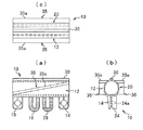
図1(a)(b)及び(c)は本発明の一実施形態に係る引込み線用の防護管固定装置によって防護管を引込み線に固定した状態を示す全体図、要部拡大斜視図、及びA-A断面図であり、図2は引込み線用の防護管の外観斜視図であり、図3(a)(b)及び(c)は絶縁カバーの閉止状態を示す正面図、側面図、及び開放状態を示す斜視図であり、図4は弾性固定部材の構成を示す斜視図である。
Hereinafter, the present invention will be described in detail with reference to embodiments shown in the drawings.
1 (a), (b) and (c) are a general view showing a state where a protective pipe is fixed to a lead-in line by a protective pipe fixing device for a lead-in line according to one embodiment of the present invention, an enlarged perspective view of a main part, FIG. 2 is a perspective view of the appearance of a lead-in protective tube, and FIGS. 3A, 3B, and 3C are a front view and a side view showing a closed state of the insulating cover. FIG. 4 is a perspective view showing a configuration of an elastic fixing member.
本発明の引込み線用の防護管固定装置(引込み線防護管固定装置)1は、引込み線束60を挿通する筒状の貫通中空部を備え、且つ略軸方向へ伸びる切り込み線51から弾性的に開閉自在な絶縁材料から成る引込み線防護管(以下、防護管という)50を、引込み線束60に固定(位置ずれ不能、落下不能に保持)する手段であり、絶縁カバー10と、弾性固定部材40とから概略構成されている。
引込み線防護管固定装置1を用いた引込み線束60への固定構造は、引込み線束の外面に固定した弾性固定部材40と、絶縁カバーを構成する各開閉部材を閉じることによりその軸方向一端部寄りにおいて弾性固定部材を挟圧保持した状態で、絶縁カバー内の軸方向他端開口側に配置される引込み線防護管50と、を備えている。
The lead-in wire protective tube fixing device (lead-in wire protective tube fixing device) 1 of the present invention includes a cylindrical through hollow portion through which the lead-in
The structure for fixing to the lead-in
絶縁カバー10は、ヒンジ部30を介して開閉自在な一対の開閉部材12、20、及び開閉部材を閉じた状態で係止する結合片14、15、24、25を備えている。絶縁カバー10は、所要の強度、弾性を有した絶縁性樹脂板を所要形状に成形したものである。
弾性固定部材40は、防護管50を固定する引込み線の局部外周面に対して後付けにより被覆(包囲)可能であり、軸方向長が絶縁カバーの軸方向長よりも短く、且つ引込み線や絶縁カバーとの間の摩擦係数(抵抗)が大きい弾性材料から成る。
図1に示すように引込み線束60の所要箇所を包囲した状態にある防護管50の一端寄りの外周面に対して、絶縁カバー10を所定の軸方向長Lに渡って被せた状態で挟圧することにより、防護管50に対して絶縁カバー10を固定する。絶縁カバー10は、その内面に配置した弾性固定部材40を介して内部の引込み線束60を弾性的に挟圧保持した状態にあるため、防護管50が引込み線束60に対して位置ずれすることがない。
The
The
As shown in FIG. 1, the
防護管50は図2に示したように弾性を有した所定厚の絶縁樹脂材料を円筒状に構成すると共に、軸方向に延びる切り込み線51によって開閉可能に構成している。図2に示すように内部に引込み線束60を挿通していない状態では、切り込み線51の両側に位置する端縁が重なった収縮状態となっているが、引込み線束を内部に挿通することにより図1(b)に示したように拡開する。
このように防護管は、挿通する引込み線束の太さに応じて縮径、拡径できる構成とすることにより、一つのサイズの防護管を太さの異なる引込み線束に共用することが可能となる。
As shown in FIG. 2, the
In this way, the protective tube can be reduced in diameter and expanded in accordance with the thickness of the lead-in wire bundle to be inserted, so that one size of the protective tube can be shared by the lead-in wire bundles having different thicknesses. .
図3に示した絶縁カバー10は絶縁材料から構成されており、三本から成る引込み線束60の被保護部分にかぶさった状態で互いに閉じることにより弾性固定部材40を介して引込み線束に挟圧固定される2つの開閉部材12、20と、開閉部材12、20の各一端縁を開閉自在に連結するヒンジ部30とから概略構成されている。
第1開閉部材12は、凹状の内部に引込み線束を受け容れる本体13と、本体13の他端縁から突設された2つの舌状の結合片14、15、及び舌状の操作片16と、を有する。
2つの結合片14、15は、本体13の他端縁の長手方向両端部に配置されている。各結合片14、15には取付け穴14a、15aが貫通形成されている。操作片16は2つの結合片14、15の間の適所、結合片15側に偏った位置に配置されている。
The
The first opening /
The two
第2開閉部材20は、凹状の内部に引込み線束を受け容れる本体21と、本体21の他端縁から突設された2つの結合片24、25、及び操作片26と、を有する。2つの結合片24、25は、本体21の他端縁の長手方向両端部に配置されている。操作片26は結合片24、25の間の適所、結合片24側に偏った位置に配置されている。
各結合片24、25の一面には係止突起24a、25aが突設されており、引込み線束を各本体13、21の凹所により挟んだ状態でヒンジ部30を中心として両開閉部材13、21を閉じた時に各係止突起24a、25aが各結合片24、25の取付け穴14a、15a内に圧入して両開閉部材を開放不能に保持する。
The second opening /
弾性固定部材40は、例えば図4に示すように弾性変形が可能なゴム、樹脂等の絶縁性の弾性体を管状(中空円筒状)に構成し、軸方向へ伸びる開閉部(切り込み線)41を拡開することにより貫通穴42内に引込み線束を嵌合させ、嵌合させた後は開閉部41を閉じることができる。弾性固定部材40はその摩擦力により絶縁カバー内面と引込み線束とを固定して位置ずれや脱落を防止する手段である。
弾性固定部材40は、引込み線束の外面を包囲するように予め両面テープ、接着剤等により取付けてもよいし、絶縁カバーの一端寄りの内面に接着等により予め取り付けておいても良い。
弾性固定部材40は適用対象となる引込み線束の太さに応じて肉厚、直径の異なるものを使用してもよいし、剥離可能な二層、或いは三層構造とすることにより、引込み線の太さの変化に対応させてその厚さを変化させるようにしてもよい。
なお、図示した弾性固定部材の構成例では管状、或いは中空円筒状としたが、板状の弾性材料を管状に丸めて使用してもよい。
For example, as shown in FIG. 4, the elastic fixing
The elastic fixing
The elastic fixing
In the illustrated configuration example of the elastic fixing member, a tubular or hollow cylindrical shape is used, but a plate-like elastic material may be rolled into a tubular shape.
また、弾性固定部材40の軸方向長は図示した例では絶縁カバーの軸方向長の1/4程度であるがこれは一例に過ぎず、弾性固定部材を絶縁カバーの1/4を越える軸方向長としてもよい。要するに弾性固定部材40が絶縁カバーを引込み線束に充分に固定することができ、且つ弾性固定部材が存在しない絶縁カバーの内部において絶縁カバーが防護管を充分な挟圧力で保持することができればよい。
なお、図1における防護管の左側の開口部をビニルテープ、その他の適当な封止部材によって閉塞することにより雨水の浸入を防ぐようにしてもよいし、防護管や絶縁カバーに設けた図示しない排水穴から雨水を排出するようにしてもよい。
The axial length of the elastic fixing
It should be noted that the opening on the left side of the protective tube in FIG. 1 may be blocked by vinyl tape or other suitable sealing member to prevent rainwater from entering, or not shown in the protective tube or insulating cover. Rainwater may be discharged from the drain hole.
次に、図5(a)(b)(c)乃至(d)は防護管固定装置1を用いて防護管を引込み線束に固定する取付け手順の一例の説明図である。
取付け手順としては種々考えられるが、一つの方法は、図5(a)に示すようにまず弾性固定部材40を予め引込み線束60の所定位置を包囲した状態で取り付けて(仮固定して)おいてから、弾性固定部材の外面全体を覆うように絶縁カバー10の一端寄り部分(軸方向下側部分)を被せた状態で開閉部材12、20を閉じてから結合片14、15と結合片24、25とを結合させる((b))。続いて、弾性固定部材が存在しない絶縁カバーの他端(軸方向上側)開口部から、予め引込み線束の外周に嵌合させておいた防護管50を一端から差し込む((c)(d))。引込み線束は通常電柱等の高所から下方に位置する需要家の設備に向けて斜めに下向きに配線されるため、弾性固定部材を絶縁カバー内に差し込んでおけば絶縁カバーによる挟圧保持力と重力によって防護管50が絶縁カバーから脱落することはない。
Next, FIGS. 5A, 5 </ b> B, 5 </ b> C, and 5 </ b> D are explanatory diagrams of an example of an attachment procedure for fixing the protective tube to the lead-in wire bundle using the protective
Although various attachment procedures are conceivable, as shown in FIG. 5A, one method is to first attach (temporarily fix) the elastic fixing
なお、弾性固定部材40を予め絶縁カバーを構成する各開閉部材12、20の内面の所要位置に接着しておき、絶縁カバーを引込み線束に被せて固定する作業と同時に弾性固定部材の引込み線束への固定が完了するようにすれば、弾性固定部材を引込み線束に取り付ける手間を省くことができる。
絶縁カバーと防護管との摩擦力を高めて位置ずれや抜け落ちを防止するために、絶縁カバーの開閉部材の内面に摩擦抵抗の高いゴム、樹脂等から成る滑り止めを予め積層しておいてもよい。
また、絶縁カバーに差し込んだ防護管と絶縁カバーとの境界をビニルテープ等で固定するようにしてもよい。
なお、上記の組立作業は、通常は活線用の先端工具を取り付けた操作棒と絶縁ヤットコ等を用いて実施される。
The elastic fixing
In order to increase the frictional force between the insulating cover and the protective tube to prevent displacement and falling off, an anti-slip made of rubber, resin, etc. with high frictional resistance may be laminated in advance on the inner surface of the opening / closing member of the insulating cover. Good.
Further, the boundary between the protective tube inserted into the insulating cover and the insulating cover may be fixed with vinyl tape or the like.
Note that the above assembling work is usually carried out using an operating rod, an insulating jacket, etc., to which a tip tool for live wires is attached.
上記実施形態では図5(b)のように絶縁カバー10を完全に閉じることにより引込み線に固定してから他端開口から防護管を差し込んだが、絶縁カバーを完全に閉じる前に防護管を差し込むようにしてもよい。即ち、図示説明しないが、弾性固定部材40を介して絶縁カバーを引込み線束の外面にセットする際に弾性固定部材を配置した一端寄りの結合片14、24だけを結合させておき、他方の結合片15、25は結合しないでおく。このような状態では軸方向上側に位置する絶縁カバーの開口部は完全には閉じておらず内径が緩やかとなっている。このため、防護管の一端を差し込む際の抵抗が少なくなり、弾性固定部材40と接する位置まで容易に差し込むことができ、差込み完了後に結合片15、25を閉じればよい。
或いは、弾性固定部材40を引込み線束の外面に固定してから防護管の一端内面により弾性固定部材40の外面を覆うように防護管を引込み線束外面にセットし、この状態で防護管の一端に絶縁カバー10を被せて固定してもよい。この場合、防護管の一端は弾性固定部材と絶縁カバーとによって挟圧保持されるので、固定が確実となる。
In the above embodiment, as shown in FIG. 5B, the insulating
Alternatively, after the elastic fixing
次に、図6(a)(b)及び(c)は活線用の先端工具を取り付けた絶縁操作棒と絶縁ヤットコを用いて上記絶縁カバーを引込み線束に取り付ける手順の一例を示している。
図6(a)(b)(c)では先端工具としてのカバー押え具100によって絶縁カバー10を引込み線束60に固定(係止)する手順を示している。
この作業の前提として、弾性固定部材40によって三本の引込み線から成る引込み線束60を包囲した状態で取り付けておく。
絶縁操作棒(ホットスティック)110の先端に取り付けられたカバー押え具100は先端に絶縁カバー10の外面に対応した形状を有したフック部101を有すると共に、その下方には絶縁カバーの2つの操作片16、26のうちの一方を挟持する挟持部102が設けられている。
Next, FIGS. 6 (a), 6 (b) and 6 (c) show an example of a procedure for attaching the insulating cover to the lead-in wire bundle by using an insulating operation rod and an insulating jacket attached with a hot wire tip tool.
6 (a), 6 (b), and 6 (c) show a procedure for fixing (locking) the insulating
As a premise of this work, the elastic fixing
The
2つの開閉部材12、20が開放状態にある絶縁カバー10を、引込み線束(弾性固定部材)に被せる際には、本例では挟持部102によって操作片26を挟持することによって開放部を下向きにした状態で絶縁カバー10全体を図6(a)に示したように引込み線束60よりも上方に一旦差し上げる。絶縁カバー10の開放部を引込み線束の取付け部位の上方に位置させた状態で絶縁カバーを下降させて絶縁カバーの内面(開閉部材間)に弾性固定部材40の外面を接触させてから更にカバー押え具100を下降させると挟持部102から操作片26が離脱し、図6(b)(c)の状態となる。(b)の状態ではカバー押え具100のフック部101によって絶縁カバー10を押さえ込むことにより引込み線束に仮係止した状態となっている。
When covering the insulating
次に、図6(c)のように絶縁ヤットコ130を用いた各結合片同志の圧着作業が実施される。即ち、一人の作業員がカバー押え具100によって絶縁カバー10を引込み線束60に押さえつつ、他方の作業員が絶縁ヤットコ130を用いて一方の結合片14、24を挟み込んで圧着する。次いで、カバー押え具100を絶縁カバーから取外し、他方の結合片15、25を圧着する。
この取付け作業を完了した状態が図1、図5(b)に夫々示した状態である。
このようにして絶縁カバー10を引込み線束60に位置決め固定した状態で、絶縁カバーの上側開口部から防護管50の一端を差し込むことにより防護管の設置作業を完了することができる。
なお、上述のように当初一方の結合片14、24のみを圧着状態として他方の結合片15、25を非結合状態としておくことにより、防護管を差し込む側の開口部を緩くしておくことができ、防護管の挿入作業を容易化することができる。防護管の挿入後に結合片15、25を結合すればよい。
Next, as shown in FIG. 6 (c), the crimping operation of the respective connecting pieces using the insulating
The state where the mounting operation is completed is the state shown in FIGS. 1 and 5B, respectively.
With the insulating
As described above, it is possible to loosen the opening on the side where the protective tube is inserted by initially setting only one of the
次に、図7(a)(b)及び(c)は本発明の他の実施形態に係る引込み線防護管の固定装置の構成を示す正面図、側面図、及び平面図である。また、図8はガイド部材を利用した防護管の取付け手順を説明する図である。
この引込み線防護管の固定装置は、絶縁カバー10を構成する各開閉部材12、20の外面に、引込み線防護管50を開放させながら各開閉部材を軸方向に沿って移動させて絶縁カバー内部を貫通する引込み線束の外面に移動させることを可能とするガイド部材35を突設した構成が特徴的である。
即ち、各開閉部材の外面に絶縁カバーの軸方向と交差する方向へ延びるガイド部材35を夫々突設し、各ガイド部材は夫々の先端縁35aにより引込み線防護管の内面を支持して該引込み線防護管の開放状態を維持しつつ該引込み線防護管が軸方向へ移動することを許容する構成を備えている。
各開閉部材の側面からのガイド突起の突出長は一定であってもよいし、図7(a)の左方へ向かう程テーパー状に拡開するようにしてもよい。
Next, FIGS. 7A, 7B, and 7C are a front view, a side view, and a plan view showing a configuration of a securing device for a lead-in wire protective tube according to another embodiment of the present invention. FIG. 8 is a diagram for explaining a procedure for attaching a protective tube using a guide member.
The fixing device for the lead-in wire protection tube is formed by moving each open / close member along the axial direction while opening the lead-in
That is, a
The protruding length of the guide protrusion from the side surface of each opening / closing member may be constant, or may be expanded in a tapered shape toward the left in FIG.
ガイド部材35を利用して防護管50を引込み線束にセットする際には、まず図8に示したように絶縁カバー10の内部に引込み線束60を挿通して両開閉部材を閉じた状態において、切り込み線51から一端を開放させた防護管50−1の内面を各開閉部材の側面に突設した両ガイド部材35の先端縁35aに被せる。続いて、防護管を軸方向(図8の左方向)へ移動させると、移動の過程でもガイド部材の先端縁35aが防護管50−2、50−3の内面と接触しつつこれらを開放させた状態を維持する。符号50−4で示すように防護管の先端(左端)がガイド部材及び開閉部材の左端を越えた後でも防護管の先端は開放状態を維持しているため、絶縁カバーの左開口部から延びている引込み線束60の外面に被さった状態で進行する。防護管50−4が左方向へ進行することにより防護管の左端側がガイド部材35から離間するに連れて、ガイド部材による拡開作用の影響力が低下するため原形復帰力によって徐々に閉じて行き、引込み線束の外面に閉じた状態で被さってゆく。防護管の左方への移動の進行により、防護管の後続部位も順次引込み線束上に移行する。防護管の後端がガイド部材及び開閉部材の左端を越えた時に防護管全体の引込み線束上への移行が完了し、自らの原形復帰力により閉じた状態となって引込み線束の外面に被着する(50−5)。
When the
防護管を引込み線束側に完全に移行させてから、絶縁カバーの他端開口部からその内部に防護管を差し込む等の組み付け作業を実施する手順となる。
なお、各開閉部材の側面からのガイド部材35の突出長を図面左方へ向かう程テーパー状となるように増大させた場合には、防護管が左方へ移動するに連れて防護管の開放量が増大して行くため、防護管の装着がスムーズとなる。
ガイド部材35が存在しない場合には活線用の工具を装備した絶縁操作棒や絶縁ヤットコを用いて防護管を全長に渡って開放させながら引込み線束の外面に被せる煩雑な作業を行う必要があったが、本実施形態のように絶縁カバー自体にガイド部材35を設ければ、防護管の一端寄り開口部側から順次開放させて各ガイド部材の先端縁35aに引っ掛ければ防護管の開放状態を確保、維持することができる。この状態でガイド部材に沿って防護管を軸方向へ移動させることにより防護管は絶縁カバーを乗り越えて引込み線側に移行することができる。
After the protective tube is completely moved to the lead-in wire bundle side, the assembly work such as inserting the protective tube into the inside from the other end opening of the insulating cover is performed.
When the protruding length of the
When the
<本発明の構成、作用、効果のまとめ>
第1の本発明に係る引込み線防護管固定装置1は、引込み線束60を挿通する貫通中空部を備え、且つ略軸方向へ伸びる切り込み線51から弾性的に開閉自在な引込み線防護管50を引込み線束の外面に固定する手段であり、ヒンジ部30を介して開閉自在な一対の開閉部材12、20、及び該一対の開閉部材を閉じた状態で結合する結合片14、15、24、25を備えた絶縁カバー10と、引込み線防護管を固定する引込み線束の外面に対して取付け可能であり、軸方向長が前記絶縁カバーの軸方向長よりも短い弾性固定部材40と、を備えたことを特徴とする。
絶縁性樹脂からなる管体である引込み線防護管内に引込み線束を挿通した状態で引込み線束に固定する手段としての引込み線防護管固定装置1は、絶縁カバー10と、弾性固定部材40の2部品から成るシンプルな構造である。従来のビニルテープやバインド線による固定において発生していた不具合である引込み線の損傷等の問題を一挙に解決することができる。
<Summary of Configuration, Action, and Effect of the Present Invention>
The lead-in wire protection
The lead-in wire protective
第2の本発明に係る引込み線防護管固定装置1は、各開閉部材の外面に絶縁カバーの軸方向と交差する方向へ延びるガイド部材35を夫々突設し、各ガイド部材は夫々の先端縁により引込み線防護管50の内面を支持して該引込み線防護管の開放状態を維持しつつ該引込み線防護管が軸方向へ移動することを許容する構成を備えている。
引込み線防護管は軸方向へ延びる切り込み線51を有した管体であり、これを引込み線束の外面に被せるためには間接活線工具を用いて切り込み線から防護管を開放状態とする必要がある。防護管が長尺な場合にはこのような活線用の先端工具を取り付けた絶縁操作棒と絶縁ヤットコを駆使した作業が必要となるが容易ではない。
In the lead-in wire protective
The lead-in line protection pipe is a pipe body having a
本発明によれば、各ガイド部材の先端縁により引込み線防護管を開放させた状態としつつ該引込み線防護管を軸方向に移動させることにより、引込み線防護管を絶縁カバー内部を貫通する引込み線束の外面に移動させることができる。
即ち、本発明によれば、防護管の軸方向一端側を開放して各ガイド部材の先端縁に防護管の内側面をあてがうことにより防護管の開放状態を維持した後は、絶縁カバーの外面に沿って防護管を軸方向へ移動させれば、絶縁カバーの一端を越えて引込み線束側へ移行した防護管部分は順次引込み線束外面に被さった状態で移行してゆくので作業が容易、且つ確実となる。
防護管を引込み線束側に移行させてから、絶縁カバーの他端開口部からその内部に差し込む等の組み付け作業を実施することなる。
According to the present invention, the lead-in wire protection tube is pulled through the inside of the insulating cover by moving the lead-in wire protection tube in the axial direction while keeping the lead-in wire protection tube open by the leading edge of each guide member. It can be moved to the outer surface of the wire bundle.
That is, according to the present invention, after maintaining the open state of the protective tube by opening one end side of the protective tube in the axial direction and applying the inner surface of the protective tube to the leading edge of each guide member, the outer surface of the insulating cover If the protective tube is moved in the axial direction along the direction of It will be certain.
After the protective tube is moved to the lead-in wire bundle side, an assembling operation such as inserting into the inside from the other end opening of the insulating cover is performed.
第3の本発明に係る防護管固定装置の引込み線への固定構造は、引込み線束の外面に固定した弾性固定部材40と、各開閉部材を閉じることによりその軸方向一端部寄りにおいて弾性固定部材を挟圧保持した状態で、絶縁カバー内の軸方向他端開口側に配置された引込み線防護管50と、を備えたことを特徴とする。
弾性固定部材は絶縁カバーの軸方向一端寄りに位置しているため、絶縁カバーの他端寄りの内部には防護管を収容する空間が形成される。本固定構造ではこの空間内に防護管を取り付ける際に絶縁カバーの軸方向他端開口から引込み線防護管の一端を差し込むようにした。活線用の各種工具を用いた作業においてもこのような組み付け作業は容易である。
The structure for fixing the protective tube fixing device to the lead-in wire according to the third aspect of the present invention includes an elastic fixing
Since the elastic fixing member is located near one end in the axial direction of the insulating cover, a space for accommodating the protective tube is formed inside the other end of the insulating cover. In this fixed structure, one end of the lead-in wire protective tube is inserted from the other axial end opening of the insulating cover when the protective tube is installed in this space. Such assembling work is easy even in work using various tools for live lines.
第4の本発明に係る防護管固定装置の固定方法は、非水平な姿勢で設置された引込み線束に対する固定方法であって、引込み線束の外面に対して弾性固定部材を取り付ける工程と、弾性固定部材が軸方向下端部寄りに位置するように一対の開閉部材を閉じてから結合片により結合することにより、絶縁カバーを前記引込み線束に固定する工程と、固定部材の軸方向上側開口部内に防護管を挿入する工程と、を備えたことを特徴とする。
構成部品が少なく、組立工数も少ないため、作業性を高めて作業者の負担を大幅に軽減することができる。
引込み線は電柱等から需要家の設備に向けて下降傾斜して配線される。このため、絶縁カバーの下側寄りに弾性固定部材を配置し、絶縁カバーの上側開口部から防護管を差し込むことにより絶縁カバーの挟圧力と重力によって防護管を引込み線束に固定することができる。
According to a fourth aspect of the present invention, there is provided a method for fixing a protective tube fixing device, which is a fixing method for a retractable wire bundle installed in a non-horizontal posture, and a step of attaching an elastic fixing member to the outer surface of the retractable wire bundle; The insulating cover is fixed to the lead-in wire bundle by closing the pair of opening and closing members so that the member is positioned closer to the lower end in the axial direction, and is protected in the upper opening in the axial direction of the fixing member. And a step of inserting a tube.
Since there are few components and the number of assembly steps is small, workability can be improved and the burden on the operator can be greatly reduced.
The lead-in line is routed downward from the utility pole or the like toward the customer's equipment. For this reason, the elastic fixing member is disposed on the lower side of the insulating cover, and the protective tube can be fixed to the lead-in wire bundle by the sandwiching pressure and gravity of the insulating cover by inserting the protective tube through the upper opening of the insulating cover.
1…引込み線防護管固定装置(防護管固定装置)、10…絶縁カバー、12、20…開閉部材、13、21…本体、14、15、24、25…結合片、16…操作片、26…操作片、30…ヒンジ部、35…ガイド部材、35a…先端縁、40…弾性固定部材、41…開閉部、42…貫通穴、50…引込み線防護管、51…切り込み線、60…引込み線束、100…カバー押え具、101…フック部、102…挟持部、130…絶縁ヤットコ
DESCRIPTION OF
Claims (4)
ヒンジ部を介して開閉自在な一対の開閉部材、及び該一対の開閉部材を閉じた状態で結合する結合片を備えた絶縁カバーと、
前記引込み線防護管を固定する前記引込み線束の外面に対して取付け可能であり、軸方向長が前記絶縁カバーの軸方向長よりも短い弾性固定部材と、
を備えたことを特徴とする引込み線防護管固定装置。 A lead-in wire protective tube fixing device that includes a through-hole portion through which the lead-in wire bundle is inserted and that fixes a lead-in wire protective tube that is elastically openable and closable from a cut line extending substantially in the axial direction to the outer surface of the lead-in wire bundle,
A pair of opening and closing members that can be freely opened and closed via a hinge portion, and an insulating cover including a coupling piece that couples the pair of opening and closing members in a closed state;
An elastic fixing member that is attachable to the outer surface of the lead-in wire bundle that fixes the lead-in wire protection tube, and whose axial length is shorter than the axial length of the insulating cover;
A lead-in wire protective tube fixing device.
前記各ガイド部材は夫々の先端縁により前記引込み線防護管の内面を支持して該引込み線防護管の開放状態を維持しつつ該引込み線防護管が軸方向へ移動することを許容する構成を備えていることを特徴とする請求項1に記載の引込み線防護管固定装置。 Guide members extending in a direction intersecting the axial direction of the insulating cover are respectively provided on the outer surfaces of the opening and closing members,
Each guide member is configured to support the inner surface of the lead-in wire protection tube by a respective leading edge to allow the lead-in wire protection tube to move in the axial direction while maintaining the open state of the lead-in wire protection tube. The lead-in wire protective tube fixing device according to claim 1, further comprising:
前記引込み線束の外面に固定した前記弾性固定部材と、前記各開閉部材を閉じることによりその軸方向一端部寄りにおいて前記弾性固定部材を挟圧保持した状態で、前記絶縁カバー内の軸方向他端開口側に配置される前記引込み線防護管と、を備えたことを特徴とする防護管固定装置の引込み線への固定構造。 A structure for fixing the lead-in wire protective tube fixing device according to claim 1 or 2 to the lead-in wire,
The elastic fixing member fixed to the outer surface of the lead-in wire bundle, and the other axial end in the insulating cover in a state where the elastic fixing member is clamped and held near the one end in the axial direction by closing the opening and closing members. A structure for fixing a protection tube fixing device to a service wire, comprising the service wire protection tube arranged on the opening side.
前記引込み線束の外面に対して前記弾性固定部材を取り付ける工程と、
前記弾性固定部材が軸方向下端部寄りに位置するように前記一対の開閉部材を閉じてから前記結合片により結合することにより、前記絶縁カバーを前記引込み線束に固定する工程と、
前記固定部材の軸方向上側開口部内に前記防護管を挿入する工程と、
を備えたことを特徴とする防護管固定装置の固定方法。 The method for fixing a protective tube fixing device according to claim 1 or 2, with respect to the lead-in wire bundle installed in a non-horizontal posture,
Attaching the elastic fixing member to the outer surface of the lead-in wire bundle;
Fixing the insulating cover to the lead-in wire bundle by closing the pair of opening and closing members so that the elastic fixing member is positioned closer to the lower end in the axial direction and then connecting with the connecting piece;
Inserting the protective tube into the axially upper opening of the fixing member;
A method for fixing a protective tube fixing device.
Priority Applications (1)
| Application Number | Priority Date | Filing Date | Title |
|---|---|---|---|
| JP2016080980A JP2017192234A (en) | 2016-04-14 | 2016-04-14 | Lead-in wire protective tube fixing device, structure to fix protective tube fixing device to lead-in wire, and method to fix protective tube fixing device |
Applications Claiming Priority (1)
| Application Number | Priority Date | Filing Date | Title |
|---|---|---|---|
| JP2016080980A JP2017192234A (en) | 2016-04-14 | 2016-04-14 | Lead-in wire protective tube fixing device, structure to fix protective tube fixing device to lead-in wire, and method to fix protective tube fixing device |
Publications (1)
| Publication Number | Publication Date |
|---|---|
| JP2017192234A true JP2017192234A (en) | 2017-10-19 |
Family
ID=60086211
Family Applications (1)
| Application Number | Title | Priority Date | Filing Date |
|---|---|---|---|
| JP2016080980A Pending JP2017192234A (en) | 2016-04-14 | 2016-04-14 | Lead-in wire protective tube fixing device, structure to fix protective tube fixing device to lead-in wire, and method to fix protective tube fixing device |
Country Status (1)
| Country | Link |
|---|---|
| JP (1) | JP2017192234A (en) |
Cited By (1)
| Publication number | Priority date | Publication date | Assignee | Title |
|---|---|---|---|---|
| CN108599049A (en) * | 2018-06-15 | 2018-09-28 | 国网宁夏电力有限公司宁东供电公司 | Conductor wire the end of a thread insulation protection device |
Citations (2)
| Publication number | Priority date | Publication date | Assignee | Title |
|---|---|---|---|---|
| JPH0739234U (en) * | 1993-12-25 | 1995-07-14 | 大東電材株式会社 | Fixture of protective tube for overhead distribution line |
| JP2004159452A (en) * | 2002-11-07 | 2004-06-03 | Tokyo Electric Power Co Inc:The | Cable protective cover and its mounting method |
-
2016
- 2016-04-14 JP JP2016080980A patent/JP2017192234A/en active Pending
Patent Citations (2)
| Publication number | Priority date | Publication date | Assignee | Title |
|---|---|---|---|---|
| JPH0739234U (en) * | 1993-12-25 | 1995-07-14 | 大東電材株式会社 | Fixture of protective tube for overhead distribution line |
| JP2004159452A (en) * | 2002-11-07 | 2004-06-03 | Tokyo Electric Power Co Inc:The | Cable protective cover and its mounting method |
Cited By (1)
| Publication number | Priority date | Publication date | Assignee | Title |
|---|---|---|---|---|
| CN108599049A (en) * | 2018-06-15 | 2018-09-28 | 国网宁夏电力有限公司宁东供电公司 | Conductor wire the end of a thread insulation protection device |
Similar Documents
| Publication | Publication Date | Title |
|---|---|---|
| JP4959406B2 (en) | Insulation cover device | |
| JP4566767B2 (en) | Insulation sleeve cover | |
| JP2017192234A (en) | Lead-in wire protective tube fixing device, structure to fix protective tube fixing device to lead-in wire, and method to fix protective tube fixing device | |
| JP4979541B2 (en) | Cable fixing method | |
| JP2008178280A (en) | Cable fixture | |
| JP5960233B2 (en) | Indirect hot line cotter and indirect hot wire adapter | |
| JP3290401B2 (en) | Insulation cover for overhead distribution lines and method of mounting the same | |
| JP2007282428A (en) | Anchor structure of overhead insulated wire | |
| JP4272914B2 (en) | Cover for repairing electric wire and its mounting method | |
| JP4832233B2 (en) | Conduit | |
| JP2761630B2 (en) | Terminal cap for underline | |
| JP2008293664A (en) | Protective cover | |
| JP2017163794A (en) | Processing method of wire end and armor of anchor terminal | |
| KR101785718B1 (en) | Clamping apparatus for distribution lines | |
| JP5563115B1 (en) | Wire insulation protective cover and its mounting method | |
| JP2008178181A (en) | High voltage insulation cover | |
| JP2010130867A (en) | Cable branch part waterproofing cover and cable branch part waterproofing treatment method | |
| JP5116711B2 (en) | Protective cover | |
| US7257305B1 (en) | Method and apparatus for removing an isolation closure from a fiber optic cable | |
| CN216980897U (en) | Quick connecting device of electrical engineering circuit | |
| JP2002354622A (en) | Cable protective pipe lead-in method | |
| JP5033846B2 (en) | Mounting aid, mounting method, and detaching method | |
| CN213151548U (en) | Wire harness protective sleeve | |
| JP4833095B2 (en) | Emergency recovery closure | |
| JP2016144328A (en) | Connector cover |
Legal Events
| Date | Code | Title | Description |
|---|---|---|---|
| A621 | Written request for application examination |
Free format text: JAPANESE INTERMEDIATE CODE: A621 Effective date: 20190320 |
|
| A977 | Report on retrieval |
Free format text: JAPANESE INTERMEDIATE CODE: A971007 Effective date: 20191211 |
|
| A131 | Notification of reasons for refusal |
Free format text: JAPANESE INTERMEDIATE CODE: A131 Effective date: 20191217 |
|
| A02 | Decision of refusal |
Free format text: JAPANESE INTERMEDIATE CODE: A02 Effective date: 20200630 |