JP2017191684A - Battery pack - Google Patents
Battery pack Download PDFInfo
- Publication number
- JP2017191684A JP2017191684A JP2016079781A JP2016079781A JP2017191684A JP 2017191684 A JP2017191684 A JP 2017191684A JP 2016079781 A JP2016079781 A JP 2016079781A JP 2016079781 A JP2016079781 A JP 2016079781A JP 2017191684 A JP2017191684 A JP 2017191684A
- Authority
- JP
- Japan
- Prior art keywords
- connector
- housing
- hole
- relay terminal
- battery module
- Prior art date
- Legal status (The legal status is an assumption and is not a legal conclusion. Google has not performed a legal analysis and makes no representation as to the accuracy of the status listed.)
- Granted
Links
Images


Classifications
-
- Y—GENERAL TAGGING OF NEW TECHNOLOGICAL DEVELOPMENTS; GENERAL TAGGING OF CROSS-SECTIONAL TECHNOLOGIES SPANNING OVER SEVERAL SECTIONS OF THE IPC; TECHNICAL SUBJECTS COVERED BY FORMER USPC CROSS-REFERENCE ART COLLECTIONS [XRACs] AND DIGESTS
- Y02—TECHNOLOGIES OR APPLICATIONS FOR MITIGATION OR ADAPTATION AGAINST CLIMATE CHANGE
- Y02E—REDUCTION OF GREENHOUSE GAS [GHG] EMISSIONS, RELATED TO ENERGY GENERATION, TRANSMISSION OR DISTRIBUTION
- Y02E60/00—Enabling technologies; Technologies with a potential or indirect contribution to GHG emissions mitigation
- Y02E60/10—Energy storage using batteries
Landscapes
- Battery Mounting, Suspending (AREA)
Abstract
【課題】コネクタの交換作業が容易かつ効率的に行うことができる電池パックを提供する。【解決手段】電池パック1は、電池モジュール20と、電池モジュールの充電を行うための充電器に接続可能なコネクタ70と、電池モジュールとコネクタとの間の接続を中継する中継端子80と、電池モジュールと中継端子とを収容する筐体10と、を備え、筐体は、コネクタを内挿可能な貫通孔12cと、コネクタと中継端子との接続箇所にアクセス可能な作業孔13bと、筐体の内部において電池モジュールが配置される領域A1と接続箇所が配置される領域A2とをそれぞれ隔てて区画する区画部17と、を有し、コネクタは、貫通孔に内挿された状態で筐体に固定されている。【選択図】図2PROBLEM TO BE SOLVED: To provide a battery pack capable of easily and efficiently exchanging a connector. A battery pack (1) includes a battery module (20), a connector (70) that can be connected to a charger for charging the battery module, a relay terminal (80) that relays the connection between the battery module and the connector, and a battery. A housing 10 for accommodating the module and the relay terminal is provided. The housing has a through hole 12c into which a connector can be inserted, a work hole 13b accessible to a connection point between the connector and the relay terminal, and the housing. A partition part 17 for partitioning an area A1 in which the battery module is arranged and an area A2 in which the connection point is arranged, respectively, and the connector is inserted in the through hole. It is fixed to. [Selection diagram] Figure 2
Description
本発明は、電池パックに関する。 The present invention relates to a battery pack.
電池セルの配列体を含んで構成された電池モジュールを筐体内に収容してなる電池パックが知られている。このような電池パックは、電気自動車又はフォークリフトなど、車両のバッテリとして使用される。このような電池パックには、電池モジュールに充電を行うためのケーブルを接続するためのコネクタが設けられている。例えば、特許文献1には、有底筒状の本体部と本体部の開口部を覆う蓋部材とによって形成される筐体の内部に、複数の電池モジュールと、ハーネス等によって電池モジュールと電気的に接続されるコネクタと、を備える電池パックが開示されている。
There is known a battery pack in which a battery module configured to include an array of battery cells is housed in a casing. Such a battery pack is used as a battery of a vehicle such as an electric vehicle or a forklift. Such a battery pack is provided with a connector for connecting a cable for charging the battery module. For example, in
このような電池パックでは、コネクタを繰返し抜き差しすることによって、例えば、端子接合部の摩耗し、コネクタの抵抗値が上昇し、通電部分の温度が上昇することがある。このため、例えば、所定温度以上になるようなコネクタは交換される。この場合、作業者は、本体部に連結された蓋部材を取り外し、電池モジュール又はジャンクションボックス等の中継装置とコネクタとの配線接続を解除し、コネクタを取り外す一連の取外処理を実施し、その後、今度は、取外処理とは逆の手順の取付処理を実施してコネクタを取り付ける。 In such a battery pack, when the connector is repeatedly inserted and removed, for example, the terminal joint portion may be worn, the resistance value of the connector may increase, and the temperature of the energized portion may increase. For this reason, for example, a connector that has a predetermined temperature or higher is replaced. In this case, the operator removes the lid member connected to the main body, releases the wiring connection between the relay device such as the battery module or the junction box and the connector, performs a series of removal processes for removing the connector, and thereafter This time, the connector is attached by performing the attachment process in the reverse order of the removal process.
上記交換作業においては、蓋部材等を本体部から分離したり、配線の解除及び接続をしたりする等、交換対象であるコネクタの大きさに対し作業範囲が広範囲に及ぶので非効率である。 The above replacement work is inefficient because the work range is wide with respect to the size of the connector to be exchanged, such as separating the lid member and the like from the main body, and releasing and connecting the wiring.
そこで、本発明の目的は、コネクタの交換作業を容易かつ効率的に行うことができる電池パックを提供することにある。 Accordingly, an object of the present invention is to provide a battery pack capable of easily and efficiently performing a connector replacement operation.
本発明の電池パックは、電池モジュールと、電池モジュールの充電を行うための充電器に接続可能なコネクタと、電池モジュールとコネクタとの間の接続を中継する中継端子と、電池モジュールと中継端子とを収容する筐体と、を備え、筐体は、コネクタを内挿可能な貫通孔と、コネクタと中継端子との接続箇所にアクセス可能な作業孔と、筐体の内部において電池モジュールが配置される領域と接続箇所が配置される領域とをそれぞれ隔てて区画する区画部と、を有し、コネクタは、貫通孔に内挿された状態で筐体に固定されている。 The battery pack of the present invention includes a battery module, a connector connectable to a charger for charging the battery module, a relay terminal that relays connection between the battery module and the connector, a battery module, and a relay terminal. And a housing in which the battery module is disposed inside the housing, a through hole in which the connector can be inserted, a work hole in which the connection portion between the connector and the relay terminal can be accessed, and And a partition portion that partitions the connection portion and the region where the connection portion is disposed, and the connector is fixed to the housing in a state of being inserted into the through hole.
この構成の電池パックの筐体には、コネクタと中継端子との接続箇所にアクセス可能な作業孔が設けられている。これにより、作業者は、筐体を分解等することなく、作業孔を介して容易に上記接続箇所に手を届かせることができるので、コネクタの交換作業が容易に行える。また、作業孔を介して交換作業を行う場合、部品等を電池モジュールが配置される領域に落としてしまった場合、当該部品を取り出すのが困難になる。この構成の電池パックの筐体には、筐体の内部において電池モジュールが配置される領域と接続箇所が配置される領域とをそれぞれ隔てて区画する区画部が設けられている。これにより、コネクタの交換作業時に部品等を落とした場合でも、当該部品は、電池モジュールが配置される領域に到達することはなく接続箇所が配置される領域に留まる。この結果、コネクタの交換作業を効率的に行うことができる。以上に説明したように、この電池パックでは、コネクタの交換作業を容易かつ効率的に行うことができる。 The battery pack housing of this configuration is provided with a work hole that allows access to the connection location between the connector and the relay terminal. As a result, the operator can easily reach the connection location through the work hole without disassembling the housing, so that the connector can be easily replaced. Further, when the replacement work is performed through the work hole, it is difficult to take out the part if the part or the like is dropped in the region where the battery module is disposed. The casing of the battery pack having this configuration is provided with a partition section that partitions the area in which the battery module is disposed and the area in which the connection location is disposed. As a result, even if a component or the like is dropped during the connector replacement operation, the component does not reach the region where the battery module is disposed, but remains in the region where the connection location is disposed. As a result, the connector replacement work can be performed efficiently. As described above, in this battery pack, the connector replacement operation can be easily and efficiently performed.
本発明の電池パックは、コネクタに設けられ、充電器が接続される方向から当該コネクタを見た際の外形から突出する係止部を更に備え、コネクタは、貫通孔に内挿された状態、かつ、当該コネクタに設けられた係止部が筐体の外側面に接触された状態で当該筐体に固定されていてもよい。 The battery pack of the present invention further includes a locking portion provided on the connector and protruding from the outer shape when the connector is viewed from the direction in which the charger is connected, and the connector is inserted into the through hole, And the latching | locking part provided in the said connector may be fixed to the said housing | casing in the state contacted to the outer surface of the housing | casing.
この電池パックでは、係止部を備えることにより、筐体の外部からコネクタを取り付けることが容易に可能になる。すなわち、筐体の外部から筐体の貫通孔にコネクタを差し込み、係止部が筐体の外側面に接触するまで押し込むだけで位置決めが完了する。また、筐体に固定されたボルト等を外し、筐体の外部からコネクタを引き出すことによりコネクタを筐体から取り外せる。このような構成により、コネクタから延びる上記中継端子に接続するためのケーブル等が曲げ難い製品であったとしても、容易に当該ケーブルを中継端子に接続させることができる。 In this battery pack, it is possible to easily attach the connector from the outside of the housing by providing the locking portion. That is, the positioning is completed simply by inserting the connector into the through-hole of the housing from the outside of the housing and pushing it in until the locking portion contacts the outer surface of the housing. Moreover, the connector can be removed from the housing by removing the bolts fixed to the housing and pulling out the connector from the outside of the housing. With such a configuration, even if a cable or the like for connecting to the relay terminal extending from the connector is a product that is difficult to bend, the cable can be easily connected to the relay terminal.
区画部は、水平方向に延在すると共に中継端子が配置される部品載置部と、コネクタと中継端子との間に配置され、部品載置部に対して下方に凹んだ落込部と、を有しており、落込部には、筐体の内部と外部とを連通する連通孔が形成されていてもよい。 The partition portion extends in the horizontal direction and includes a component placement portion on which the relay terminal is disposed, and a drop portion disposed between the connector and the relay terminal and recessed downward with respect to the component placement portion. And a communication hole that communicates the inside and the outside of the housing may be formed in the drop portion.
この電池パックでは、コネクタを介して、例えば、塵及び水等の異物を侵入した場合であっても、当該異物は落込部に誘導されるようになるので、中継端子にまで当該異物が到達する可能性を低減できる。また、落込部に誘導された異物は、連通孔から筐体の外部に排出される。これにより、落込部より高い位置に配置される中継端子にまで異物が到達するおそれをより一層排除できる。これらの結果、異物の侵入による不具合の発生を低減させることができ、電池パックの信頼性を高めることができる。 In this battery pack, for example, even if foreign matter such as dust and water enters through the connector, the foreign matter is guided to the drop-in portion, so that the foreign matter reaches the relay terminal. The possibility can be reduced. Moreover, the foreign material induced | guided | derived to the dropping part is discharged | emitted from the communicating hole to the exterior of a housing | casing. Thereby, the possibility that a foreign substance may reach the relay terminal arranged at a position higher than the drop-in portion can be further eliminated. As a result, it is possible to reduce the occurrence of defects due to the intrusion of foreign matter, and to improve the reliability of the battery pack.
コネクタは、充電器が接続される方向に貫通する水抜孔を有しており、当該水抜穴は、連通孔として機能する位置に配置されていてもよい。 The connector has a drain hole penetrating in the direction in which the charger is connected, and the drain hole may be disposed at a position that functions as a communication hole.
この電池パックでは、コネクタが有する水抜孔を利用して、落込部に溜まった水等を筐体の外部に排出することができる。これにより、筐体等を加工等することなく、容易に連通孔を形成することができる。 In this battery pack, the water etc. accumulated in the drop-in part can be discharged to the outside of the housing by utilizing the drain hole of the connector. Thereby, a communicating hole can be easily formed, without processing a housing | casing etc.
連通孔は、落込部の底部に設けられていてもよい。 The communication hole may be provided at the bottom of the drop portion.
この電池パックでは、落込部に誘導された異物を速やかに筐体の外部に排出できるようになる。 In this battery pack, the foreign matter guided to the drop-in portion can be quickly discharged out of the casing.
本発明の電池パックは、電池モジュールと、電池モジュールの充電を行うための充電器に接続可能なコネクタと、コネクタに設けられ、充電器が接続される方向から当該コネクタを見た際の外形から突出する係止部と、電池モジュールとコネクタとの間の接続を中継する中継端子と、電池モジュールと中継端子とを収容する筐体と、を備え、筐体は、コネクタを内挿可能な貫通孔と、コネクタと中継端子との接続箇所にアクセス可能な作業孔と、を有し、コネクタは、貫通孔に内挿された状態、かつ、当該コネクタに設けられた係止部が筐体の外側面に接触された状態で当該筐体に固定されている。 The battery pack of the present invention includes a battery module, a connector connectable to a charger for charging the battery module, and an external shape when the connector is viewed from the direction in which the charger is connected. A protruding latching portion; a relay terminal that relays the connection between the battery module and the connector; and a housing that accommodates the battery module and the relay terminal, the housing penetrating through the connector. And a working hole accessible to a connection point between the connector and the relay terminal. The connector is inserted into the through hole, and a locking portion provided on the connector is provided on the housing. It is fixed to the casing in contact with the outer surface.
この電池パックでは、筐体にコネクタと中継端子との接続箇所にアクセス可能な作業孔が設けられている。これにより、作業者は、筐体を分解等することなく、作業孔を介して容易に上記接続箇所に手を届かせることができるので、コネクタの交換作業が容易に行える。また、この電池パックでは、筐体の外部からコネクタを引き出すことにより、コネクタを取り外すことが可能になり、筐体の外部から筐体の貫通孔にコネクタを差し込むことにより、コネクタを筐体に取り付けることが可能になる。コネクタから延びる上記中継端子に接続するためのケーブル等が曲げ難い製品であったとしても、容易に当該ケーブルを中継端子に接続させることができる。以上のように、この電池パックでは、コネクタの交換作業が容易かつ効率的に行うことができる。 In this battery pack, a work hole is provided in the housing so as to access a connection portion between the connector and the relay terminal. As a result, the operator can easily reach the connection location through the work hole without disassembling the housing, so that the connector can be easily replaced. In this battery pack, the connector can be removed by pulling out the connector from the outside of the housing, and the connector is attached to the housing by inserting the connector into the through hole of the housing from the outside of the housing. It becomes possible. Even if a cable or the like for connecting to the relay terminal extending from the connector is a product that is difficult to bend, the cable can be easily connected to the relay terminal. As described above, in this battery pack, the connector replacement operation can be easily and efficiently performed.
本発明の電池パックによれば、コネクタの交換作業を効率的に行うことができる。 According to the battery pack of the present invention, the connector replacement work can be performed efficiently.
以下、図面を参照して一実施形態に係る電池パック1について説明する。図面の説明において、同一要素には同一符号を付し、重複する説明を省略する。図面の寸法比率は、説明のものと必ずしも一致していない。
Hereinafter, a
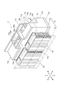
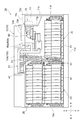
図1に示される電池パック1は、例えば、自動車及びフォークリフト等の対象装置に搭載される。電池パック1は、筐体10と、複数(本実施形態では七個)の電池モジュール20と、中継装置51と、中継端子80と、コネクタ70と、を備える。
The
筐体10は、箱状部材11と箱状部材11に接続する蓋部材15とからなる。図1及び図2に示されるように、箱状部材11は、開口部11aを有する箱体である。箱状部材11は、四角板状の底板11bと、底板11bと対向して設けられる天板11cと、底板11bの周縁から立設されるL字状の右側板11d、矩形状の左側板11e及び後側板11fと、を有している。なお、図1では、蓋部材15の後側を透視するように記載している。
The
なお、筐体10は、車両等の対象装置に搭載された際に、底板11bが鉛直方向下方に位置し、天板11cが鉛直方向上方に位置するように配置される。以下、筐体10において、底板11bが設けられる方向を「下」として、天板11cが設けられる方向を「上」として、筐体10の蓋部材15が設けられる方向を「前」として、後側板11fが設けられる方向を「後」として、右側板11dが設けられる方向を「右」として、左側板11eが設けられる方向を「左」として説明を行う。なお、これらの方向は説明の便宜のためであり、本発明を限定するものではない。
The
筐体10の右側面、すなわち、箱状部材11の右側面は、後方側が凹んだ領域であるコネクタ配置領域14aが形成されている。コネクタ配置領域14aは、後段にて詳述するコネクタ70が配置される。具体的には、コネクタ配置領域14aは、右側板11dから左方向にオフセットした第一側面11g、後側板11fから前方向にオフセットした第二側面11i、及び天板11cから下方向にオフセットすると共に右方向に下方傾斜する第三側面11hによって形成されている。第一側面11gには、コネクタ70を内挿可能な貫通孔12cが形成されている。コネクタ70は、貫通孔12cに内挿された状態で筐体10に固定されている。
On the right side surface of the
天板11cには、上方に突出すると共に後述する中継装置51が配置される部品配置領域14bが形成されている。部品配置領域14bの上方には、二つの作業孔12a,12bが形成されている。また、部品配置領域14bよりも右側の天板11c上には、作業孔13bが形成されている。作業孔13bは、後段にて詳述する中継端子80が配置される上方に形成されている。作業孔13bの開口部の大きさは、作業者が手を入れて中継端子80とコネクタ70との交換作業が可能な程度に形成されている。作業孔13bには、その開口部分を覆う蓋13aが配置されている。
The
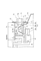
図2及び図4に示されるように、筐体10は、その内部において電池モジュール20が配置される領域A1と、コネクタ70と中継装置51との接続箇所である中継端子80が配置される領域A2と、をそれぞれ隔てて区画する区画部17を有している。区画部17によって画成された領域A2のサイズは、例えば、左右方向に180mm、前後方向に170mm、上下方向に120mmとすることができる。
As shown in FIGS. 2 and 4, the
区画部17は、第一区画板17aと、第二区画板17bと、を有している。図4及び図5に示されるように、第一区画板17aは、前方向から見た時に上下方向に延びる第一鉛直部18aと、水平方向に延在すると共に中継端子80が配置される部品載置部18bと、部品載置部18bから下方に延びる第二鉛直部18cと、を有している。図2に示されるように、第二区画板17bは、第一鉛直部18aと、部品載置部18bと、第二鉛直部18cと、天板11cと、第一側面11gと、によって囲まれる空間に対して前後方向に直交する面である。
The partition part 17 has a
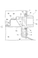
図5に示されるように、区画部17は、コネクタ70と中継端子80との間に配置され、部品載置部18bに対して下方に凹んだ落込部17cが形成されている。落込部17cは、第二区画板17b(図2参照)と、第二鉛直部18cと、第一側面11gと、後側板11fと、によって囲まれた空間である。落込部17cは、コネクタ70の水抜孔78から侵入する水及び/又は塵等が誘導される。落込部17cには、筐体10の内部と外部とを連通する連通孔が形成されている。具体的には、連通孔は、後段にて詳述するコネクタ70に形成されている水抜孔78が利用される。
As shown in FIG. 5, the partition portion 17 is disposed between the
図2に示されるように、筐体10には、七個の電池モジュール20と、中継装置51と、中継端子80と、コネクタ70と、が格納されている。七個の電池モジュール20のうち、四個の電池モジュール20は蓋部材15に固定され、三個の電池モジュール20と、中継端子80と、コネクタ70とは、箱状部材11に固定される。
As shown in FIG. 2, seven
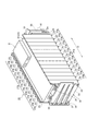
図3に示されるように、電池モジュール20は、本体部21と、第一ブラケット31と、第二ブラケット32と、弾性部材24と、を備えている。
As shown in FIG. 3, the
本体部21は、一方向(以下、「配列方向D」とも称す。)に配列された複数の電池セル22を含んでいる。本実施形態では、本体部21は13個の電池セル22を含んでいる。電池セル22は、例えば、リチウムイオン電池又はニッケル水素蓄電池などの二次電池である。複数の電池セル22のそれぞれは、セルホルダ23に保持されている。
The
セルホルダ23は、配列方向Dから見てU字状の枠体であり、当該U字の一端側を成す第一側部23aと、当該U字の他端側を成す第二側部23bと、第一側部23aと第二側部23bとを接続する底部(不図示)と、を有している。箱状部材11内において、電池モジュール20の第二側部23bは、図1に示されるように、箱状部材11の後側板11f又は蓋部材15の本体部15aに対向するように固定される。図3に戻り、複数の第一側部23aは、全体で本体部21の第一側部21aを構成している。複数の第二側部23bは、全体で本体部21の第二側部21bを構成している。
The
本体部21は、複数のセルホルダ23の上端開口を塞ぐように、複数のセルホルダ23に保持されるカバー29を含んでいる。カバー29は、複数の電池モジュール20が積層される場合において、下側に位置する電池モジュール20と、上側に位置する電池モジュール20との電気的絶縁を図る役割、及び異常時に電池セル22から吐出されるガスが上方に吹き出すことを阻止する機能を有している。カバー29には、電池モジュール20に関する各種制御を行う制御部Eが載置されている。
The
第一ブラケット31及び第二ブラケット32は、剛性の高い材料で構成され、例えば、鉄などの金属で構成されている。第一ブラケット31及び第二ブラケット32のそれぞれは、把持部33と、取付部37と、を有している。
The
把持部33は、略矩形の平板である。把持部33には、配列方向Dに沿って延びる複数のボルト(図示せず)が挿通されている。複数のボルトのそれぞれは、第一ブラケット31の把持部33から、本体部21を経由して第二ブラケット32の把持部33まで延びている。複数のボルトのそれぞれは、第二ブラケット32の把持部33側でナット35に螺合されて固定されている。
The holding
取付部37は、矩形状の把持部33の一辺に立設する平板である。取付部37は、ボルト(図示せず)により、箱状部材11又は蓋部材15に取り付けられることにより、第一ブラケット31及び第二ブラケット32が、箱状部材11又は蓋部材15に固定されている。本実施形態では、取付部37のそれぞれは、4つのボルトにより、箱状部材11又は蓋部材15に取り付けられている。
The
弾性部材24は、本体部21と第一ブラケット31との間に設けられている。弾性部材24は、ゴム及び樹脂系スポンジなどの弾性変形可能な材料からなる。弾性部材24は、その厚さ方向が配列方向Dと同一方向となるように設けられている。弾性部材24と本体部21との間には、固定プレート25が設けられている。弾性部材24は、第一ブラケット31及び第二ブラケット32の拘束範囲において電池セル22の膨張を吸収する。
The
図4及び図5に示されるように、中継装置51は、電池モジュール20とコネクタ70との間の接続を中継する。中継装置51は、例えば、ハーネス及びバスバー等の接続部材と、中継端子80と、を介してコネクタ70に対し電気的に接続されている。同様に、中継装置51は、筐体10内に収容される各電池モジュール20に対し電気的に接続されている。また、中継装置51は、電池モジュール20の監視及び制御等を行う電池制御ECU(Electronic Control Unit)(図示せず)を搭載している。電池制御ECUは、例えば、各電池モジュール20に搭載された制御部Eと通信することにより、各電池モジュール20の状態(例えば、充電状態等)に関する情報を取得したり、各電池モジュール20の動作(例えば、充放電等)を制御したりする。電池制御ECUは、例えば、コネクタ70に装着されるコネクタの種類に応じて、電池パック1の制御を行うように構成されている。以上の構成により、コネクタ70に充電器の充電コネクタが装着された場合には、電池モジュール20の充電が行われ、コネクタ70にジャンパコネクタが装着された場合には、対象装置への電力の供給が行われる。
As shown in FIGS. 4 and 5, the
中継端子80は、例えば、ハーネス及びバスバー等の接続部材によって中継装置51に電気的に接続されている。また、中継端子80は、コネクタ70から延びる第一ハーネス74、第二ハーネス75、及び第三ハーネス76によって電気的に接続されている。中継端子80の上方には、天板11cの作業孔13bが形成されている。
The
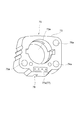
図5及び図6に示されるように、コネクタ70は、係止板(係止部)71と、本体部73と、嵌合部73aと、第一ハーネス74と、第二ハーネス75と、第三ハーネス76と、通信用ハーネス77と、水抜孔78と、を有している。コネクタ70は、貫通孔12cに内挿された状態で筐体10に固定されている。更に詳細には、コネクタ70は、本体部73に一体的に固定された係止板71を介して筐体10に固定されている。係止板71は、平板状の部材であり、充電器が接続される方向からコネクタ70を見た際の外形から突出している。コネクタ70は、貫通孔12cに内挿された状態、かつ、当該コネクタ70に一体的に固定された係止板71が筐体10の第一側面11gに接触された状態で当該筐体10に固定されている。
As shown in FIGS. 5 and 6, the
コネクタ70は、電池パック1の充電時には、充電器の充電コネクタ(図示せず)が装着され、電池パック1の電力出力時には、ジャンパコネクタ(図示せず)が装着される。本体部73は、樹脂等の材料により形成されている。嵌合部73aは、充電コネクタ又はジャンパコネクタに設けられた被嵌合部(図示せず)との接続部分であり、互いの装着を確実にする部分である。
The
第一ハーネス74は、中継端子80及び中継装置51を介して電池モジュール20に接続される正極線である。第二ハーネス75は、中継端子80及び中継装置51を介して電池モジュール20に接続される負極線であると共に、中継端子80を介して対象装置用の出力端子85bに接続される負極線でもある。すなわち、充電器の充電コネクタが、正極端子74a及び負極端子75aに接続されることにより、各電池モジュール20が充電される。第三ハーネス76は、中継端子80を介して対象装置用の出力端子85aに電気的に接続されている。すなわち、ジャンパコネクタが、正極端子74aと正極端子76aとを互いに接続することにより、対象装置に電力を供給することが可能になる。通信用ハーネス77は、充電コネクタが通信用端子77aに接続された際に、充電器と電池制御ECUとの間で情報をやり取りするための通信線である。
The
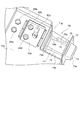
続いて、以上に説明した電池パック1におけるコネクタ70の交換手順について、図7(a)、図7(b)及び図8を参照しながら詳細に説明する。まず、作業者は、図7(a)に示される天板11cに設けられた作業孔13bを覆う蓋13aを取り外す。蓋13aは、図示しないボルト等によって固定されている。電池パック1は、蓋13aが取り外されると、図7(b)に示されるように、中継端子80に接続された第一ハーネス74、第二ハーネス75及び第三ハーネス76にアクセス可能な状態となる。第一ハーネス74は、圧着端子74bを介して第一端子82aに接続され、第二ハーネス75は、圧着端子75bを介して第二端子82b接続され、第三ハーネス76は、圧着端子76bを介して第三端子82cに接続されている。
Next, the procedure for replacing the
作業者は、作業孔13bを介して、第一ハーネス74、第二ハーネス75及び第三ハーネス76と中継端子80との接続を解除する。また、作業者は、筐体10の第一側面11gに固定されている係止板71のボルト72(図4参照)を取り外す。そして、作業者は、図8に示されるように、筐体10の第一側面11gの貫通孔12cに挿通された状態で固定されているコネクタ70を右方向に引っ張り出す。これにより、電池パック1からコネクタ70を取り外すことができる。なお、コネクタ70を取り付ける場合には、作業者は、上記で説明した取外手順とは逆の手順を実施する。このような一連の手順により、電池パック1のコネクタ70を交換することができる。
The worker releases the connection between the
続いて、以上説明した電池パック1の作用効果を説明する。上記実施形態の電池パック1では、図2に示されるように、筐体10にコネクタ70と中継端子80との接続箇所にアクセス可能な作業孔13bが設けられている。例えば、上記領域A2のサイズぐらいであれば、作業孔13bからコネクタ70と中継端子80との接続箇所にアクセス可能である。これにより、作業者は、筐体10を分解等することなく、作業孔13bを介して容易に上記接続箇所に手を届かせることができるので、コネクタ70の交換作業が容易に行える。また、作業孔13bを介して交換作業を行う場合、部品等を電池モジュール20が配置される領域A1に落としてしまった場合、当該部品を取り出すのが困難になる。上記実施形態の電池パック1の筐体10は、筐体10の内部において電池モジュール20が配置される領域A1と接続箇所が配置される領域A2とをそれぞれ隔てて区画する区画部17が設けられている。これにより、コネクタ70の交換作業時に部品等を落とした場合でも、当該部品は、電池モジュール20が配置される領域A1に到達することはなく接続箇所が配置される領域A2に留まる。この結果、コネクタ70の交換作業を効率的に行うことができる。以上に説明したように、この電池パック1では、コネクタ70の交換作業を容易かつ効率的に行うことができる。
Then, the effect of the
更に、本実施形態の電池パック1では、区画部17を設けて筐体10の内部を上方の領域A1と下方の領域A2とに区画されるので、交換作業を行う際に、感電及び発熱のおそれがある電池モジュール20が配置された領域A2に作業者の手が入ることがなく、作業の安全性を確保することができる。
Furthermore, in the
上記実施形態の電池パック1では、係止板71を備えることにより、筐体10の外部からコネクタ70を取り付けることが容易に可能になる。すなわち、筐体10の外部から筐体10の貫通孔12cにコネクタ70を差し込み、係止板71が筐体10の第一側面11gに接触するまで押し込むだけで位置決めが完了するので、後は係止板71を第一側面11gにボルト72で固定するだけでよい。また、第一側面11gに固定された係止板71からボルト72を外し、筐体10の外部からコネクタ70を引き出すことによりコネクタ70を筐体10から取り外せる。コネクタ70から延びる、中継端子80に接続するための第一ハーネス74、第二ハーネス75及び第三ハーネス76が曲げ難い製品であったとしても、容易に第一ハーネス74、第二ハーネス75及び第三ハーネス76を中継端子80に接続させることができる。
In the
上記実施形態の電池パック1では、コネクタ70を介して、例えば、塵及び水等の異物を侵入した場合であっても、当該異物は落込部17cに誘導されるので、中継端子80にまで当該異物が到達する可能性を低減できる。また、落込部17cに誘導された異物は、水抜孔78から筐体10の外部に排出される。これにより、落込部17cより高さH(図5参照)高い位置に配置される中継端子80にまで異物が到達するおそれをより一層排除できる。これらの結果、異物の侵入による不具合の発生を低減させることができ、電池パック1の信頼性を高めることができる。
In the
上記実施形態の電池パック1では、コネクタ70が有する水抜孔78を利用して、落込部17cに溜まった水等を筐体10の外部に排出することができる。これにより、筐体10等を加工等することなく、容易に落込部17cと筐体10の外部とを繋ぐ連通孔を形成することができる。
In the
以上、一実施形態について説明したが、本発明は、上記実施形態に限られるものではなく、発明の趣旨を逸脱しない範囲で種々の変更が可能である。 Although one embodiment has been described above, the present invention is not limited to the above-described embodiment, and various modifications can be made without departing from the spirit of the invention.
上記実施形態では、コネクタ70が有する水抜孔78を利用して、落込部17cに溜まった水等を筐体10の外部に排出する例を挙げて説明したが、この構成に代えて又は加えて、例えば、落込部17cの底部近傍の筐体10の第一側面11gに連通孔を設け、当該連通孔から水等を排出してもよい。
In the above-described embodiment, the example in which the
上記実施形態又は変形例では、係止板71が一体的に形成されたコネクタ70を例に挙げて説明したが、係止板71を有さない構成のコネクタ70であってもよい。ただし、コネクタ70を筐体10の外側から取り付ける構成とする場合、係止板71を有していた方が、筐体10に対するコネクタ70の位置決め等、コネクタ70を筐体10に固定する際の作業効率を高めることができる。また、コネクタは、係止板71を有さないで、筐体10の内部から取り付けが可能な構成としてもよい。
In the above-described embodiment or modification, the
上記実施形態又は変形例では、中継端子80が設けられた領域A2を区画部17によって区画する例を挙げて説明したが、例えば、中継端子80と中継装置51とを含んだ領域A2を区画部17によって区画するようにしてもよい。
In the above embodiment or the modification, the example in which the area A2 in which the
上記実施形態又は変形例では、筐体10は、その内部において電池モジュール20が配置される領域A1と、コネクタ70と中継装置51との接続箇所である中継端子80が配置される領域A2と、をそれぞれ隔てて区画する区画部17を有している例を挙げて説明したが、例えば、図9に示されるように、区画部17を有さない筐体10としてもよい。この構成の電池パック1Aであっても、係止板(係止部)71を備えることにより、筐体10の外部からコネクタ70を取り付けることが容易に可能になる。すなわち、筐体10の外部から筐体10の貫通孔12cにコネクタ70を差し込み、係止板71が第一側面11gの外側面に接触するまで押し込むだけで位置決めが完了するので、その後は係止板71をボルト72によって筐体10に固定するだけでよい。また、筐体10に固定されたボルト72を外し、筐体10の外部からコネクタ70を引き出すことによりコネクタ70を筐体10から取り外せる。コネクタ70から延びる中継端子80に接続するための第一ハーネス74、第二ハーネス75及び第三ハーネス76等のケーブルが曲げ難い製品であったとしても、容易に当該ケーブルを中継端子80に接続させることができる。
In the embodiment or the modification, the
1,1A…電池パック、10…筐体、11c…天板、11g…第一側面、11h…第三側面、11i…第二側面、12c…貫通孔、13a…蓋、13b…作業孔、17…区画部、17a…第一区画板、17b…第二区画板、17c…落込部、20…電池モジュール、22…電池セル、51…中継装置、70…コネクタ、71…係止板、74…第一ハーネス、75…第二ハーネス、76…第三ハーネス、77…通信用ハーネス、78…水抜孔、80…中継端子、A1…電池モジュールが配置される領域、A2…コネクタと中継端子との接続箇所が配置される領域。
DESCRIPTION OF
Claims (6)
前記電池モジュールの充電を行うための充電器に接続可能なコネクタと、
前記電池モジュールと前記コネクタとの間の接続を中継する中継端子と、
前記電池モジュールと前記中継端子とを収容する筐体と、
を備え、
前記筐体は、
前記コネクタを内挿可能な貫通孔と、
前記コネクタと前記中継端子との接続箇所にアクセス可能な作業孔と、
前記筐体の内部において前記電池モジュールが配置される領域と前記接続箇所が配置される領域とをそれぞれ隔てて区画する区画部と、
を有し、
前記コネクタは、前記貫通孔に内挿された状態で前記筐体に固定されている、電池パック。 A battery module;
A connector connectable to a charger for charging the battery module;
A relay terminal that relays the connection between the battery module and the connector;
A housing for housing the battery module and the relay terminal;
With
The housing is
A through hole into which the connector can be inserted, and
A working hole accessible to the connection point between the connector and the relay terminal;
A partition section for partitioning a region in which the battery module is disposed and a region in which the connection place is disposed in the housing;
Have
The battery pack, wherein the connector is fixed to the housing in a state of being inserted into the through hole.
前記コネクタは、前記貫通孔に内挿された状態、かつ、当該コネクタに設けられた前記係止部が前記筐体の外側面に接触された状態で当該筐体に固定されている、
請求項1記載の電池パック。 The connector further includes a locking portion that protrudes from an outer shape when the connector is viewed from a direction in which the charger is connected,
The connector is fixed to the housing in a state of being inserted into the through-hole and in a state where the locking portion provided in the connector is in contact with the outer surface of the housing.
The battery pack according to claim 1.
前記落込部には、前記筐体の内部と外部とを連通する連通孔が形成されている、請求項1又は2記載の電池パック。 The partition portion extends in the horizontal direction and is disposed between the component placement portion on which the relay terminal is disposed, the connector and the relay terminal, and is recessed downward with respect to the component placement portion. A drop part, and
The battery pack according to claim 1, wherein a communication hole that communicates the inside and the outside of the housing is formed in the drop portion.
前記水抜孔は、前記連通孔として機能する位置に配置されている、請求項3記載の電池パック。 The connector has a drain hole that penetrates in a direction in which the charger is connected;
The battery pack according to claim 3, wherein the drain hole is disposed at a position that functions as the communication hole.
前記電池モジュールの充電を行うための充電器に接続可能なコネクタと、
前記コネクタに設けられ、前記充電器が接続される方向から当該コネクタを見た際の外形から突出する係止部と、
前記電池モジュールと前記コネクタとの間の接続を中継する中継端子と、
前記電池モジュールと前記中継端子とを収容する筐体と、
を備え、
前記筐体は、
前記コネクタを内挿可能な貫通孔と、
前記コネクタと前記中継端子との接続箇所にアクセス可能な作業孔と、
を有し、
前記コネクタは、前記貫通孔に内挿された状態、かつ、当該コネクタに設けられた前記係止部が前記筐体の外側面に接触された状態で当該筐体に固定されている、電池パック。 A battery module;
A connector connectable to a charger for charging the battery module;
A locking part provided on the connector and protruding from the outer shape when the connector is viewed from the direction in which the charger is connected,
A relay terminal that relays the connection between the battery module and the connector;
A housing for housing the battery module and the relay terminal;
With
The housing is
A through hole into which the connector can be inserted, and
A working hole accessible to the connection point between the connector and the relay terminal;
Have
The battery pack is fixed to the housing in a state in which the connector is inserted into the through-hole and in a state in which the locking portion provided in the connector is in contact with the outer surface of the housing. .
Priority Applications (1)
| Application Number | Priority Date | Filing Date | Title |
|---|---|---|---|
| JP2016079781A JP6728918B2 (en) | 2016-04-12 | 2016-04-12 | Battery pack |
Applications Claiming Priority (1)
| Application Number | Priority Date | Filing Date | Title |
|---|---|---|---|
| JP2016079781A JP6728918B2 (en) | 2016-04-12 | 2016-04-12 | Battery pack |
Publications (2)
| Publication Number | Publication Date |
|---|---|
| JP2017191684A true JP2017191684A (en) | 2017-10-19 |
| JP6728918B2 JP6728918B2 (en) | 2020-07-22 |
Family
ID=60086515
Family Applications (1)
| Application Number | Title | Priority Date | Filing Date |
|---|---|---|---|
| JP2016079781A Active JP6728918B2 (en) | 2016-04-12 | 2016-04-12 | Battery pack |
Country Status (1)
| Country | Link |
|---|---|
| JP (1) | JP6728918B2 (en) |
Citations (4)
| Publication number | Priority date | Publication date | Assignee | Title |
|---|---|---|---|---|
| JPS60189969U (en) * | 1984-05-28 | 1985-12-16 | 富士通株式会社 | Connector mounting structure |
| JP2012212597A (en) * | 2011-03-31 | 2012-11-01 | Nec Energy Devices Ltd | Battery pack and electric bicycle |
| JP2015172411A (en) * | 2014-03-12 | 2015-10-01 | 株式会社豊田自動織機 | fastening member |
| WO2016035537A1 (en) * | 2014-09-05 | 2016-03-10 | 株式会社 豊田自動織機 | Battery pack |
-
2016
- 2016-04-12 JP JP2016079781A patent/JP6728918B2/en active Active
Patent Citations (4)
| Publication number | Priority date | Publication date | Assignee | Title |
|---|---|---|---|---|
| JPS60189969U (en) * | 1984-05-28 | 1985-12-16 | 富士通株式会社 | Connector mounting structure |
| JP2012212597A (en) * | 2011-03-31 | 2012-11-01 | Nec Energy Devices Ltd | Battery pack and electric bicycle |
| JP2015172411A (en) * | 2014-03-12 | 2015-10-01 | 株式会社豊田自動織機 | fastening member |
| WO2016035537A1 (en) * | 2014-09-05 | 2016-03-10 | 株式会社 豊田自動織機 | Battery pack |
Also Published As
| Publication number | Publication date |
|---|---|
| JP6728918B2 (en) | 2020-07-22 |
Similar Documents
| Publication | Publication Date | Title |
|---|---|---|
| CN107546346B (en) | Vehicle-mounted storage battery | |
| EP2650946B1 (en) | Battery block and secondary battery module | |
| RU2685504C2 (en) | Electrical energy storage device | |
| CN111149236B (en) | Battery pack | |
| US20190198849A1 (en) | Connection module | |
| KR20170073170A (en) | Secondary Battery Pack | |
| JP6443113B2 (en) | Battery pack manufacturing method and battery pack | |
| CN106233504A (en) | wiring module | |
| KR102093943B1 (en) | Battery module, battery pack comprising the battery module and vehicle comprising the battery pack | |
| JP7588502B2 (en) | Electrical equipment systems and battery pack type equipment | |
| EP3604095B1 (en) | Battery support structure for saddle-type vehicle | |
| US10879507B2 (en) | Onboard battery | |
| KR102092917B1 (en) | Battery pack and energy storage system comprising the battery pack | |
| JP6728918B2 (en) | Battery pack | |
| US12580270B2 (en) | Energy storage facility | |
| JP2021012802A (en) | Connection module | |
| US12603400B2 (en) | Energy storage apparatus | |
| KR102088974B1 (en) | Battery module, battery pack comprising the battery module and energy storage system comprising the battery pack | |
| JP7474060B2 (en) | Battery pack | |
| JP6705340B2 (en) | Battery pack | |
| JP2018022553A (en) | Battery pack | |
| KR102111767B1 (en) | Battery pack and vehicle comprising the battery pack | |
| JP6790595B2 (en) | Battery pack | |
| JP6525657B2 (en) | Automotive battery | |
| JP7847067B2 (en) | Battery pack and method for manufacturing a battery pack |
Legal Events
| Date | Code | Title | Description |
|---|---|---|---|
| A621 | Written request for application examination |
Free format text: JAPANESE INTERMEDIATE CODE: A621 Effective date: 20190115 |
|
| A977 | Report on retrieval |
Free format text: JAPANESE INTERMEDIATE CODE: A971007 Effective date: 20191127 |
|
| A131 | Notification of reasons for refusal |
Free format text: JAPANESE INTERMEDIATE CODE: A131 Effective date: 20191203 |
|
| A521 | Request for written amendment filed |
Free format text: JAPANESE INTERMEDIATE CODE: A523 Effective date: 20200130 |
|
| TRDD | Decision of grant or rejection written | ||
| A01 | Written decision to grant a patent or to grant a registration (utility model) |
Free format text: JAPANESE INTERMEDIATE CODE: A01 Effective date: 20200602 |
|
| A61 | First payment of annual fees (during grant procedure) |
Free format text: JAPANESE INTERMEDIATE CODE: A61 Effective date: 20200615 |
|
| R151 | Written notification of patent or utility model registration |
Ref document number: 6728918 Country of ref document: JP Free format text: JAPANESE INTERMEDIATE CODE: R151 |