JP2017191383A - Vehicle controller - Google Patents
Vehicle controller Download PDFInfo
- Publication number
- JP2017191383A JP2017191383A JP2016079121A JP2016079121A JP2017191383A JP 2017191383 A JP2017191383 A JP 2017191383A JP 2016079121 A JP2016079121 A JP 2016079121A JP 2016079121 A JP2016079121 A JP 2016079121A JP 2017191383 A JP2017191383 A JP 2017191383A
- Authority
- JP
- Japan
- Prior art keywords
- control
- collision
- host vehicle
- vehicle
- determination unit
- Prior art date
- Legal status (The legal status is an assumption and is not a legal conclusion. Google has not performed a legal analysis and makes no representation as to the accuracy of the status listed.)
- Granted
Links
- 238000000034 method Methods 0.000 claims description 62
- 238000004441 surface measurement Methods 0.000 claims description 16
- 238000004364 calculation method Methods 0.000 claims description 6
- 230000001747 exhibiting effect Effects 0.000 abstract description 5
- 239000012080 ambient air Substances 0.000 abstract 1
- 238000003384 imaging method Methods 0.000 description 11
- 230000007704 transition Effects 0.000 description 5
- 239000013598 vector Substances 0.000 description 5
- 230000000694 effects Effects 0.000 description 3
- 230000001133 acceleration Effects 0.000 description 1
- 238000010586 diagram Methods 0.000 description 1
- 230000008014 freezing Effects 0.000 description 1
- 238000007710 freezing Methods 0.000 description 1
- 230000003287 optical effect Effects 0.000 description 1
- 238000003825 pressing Methods 0.000 description 1
Images


Classifications
-
- B—PERFORMING OPERATIONS; TRANSPORTING
- B62—LAND VEHICLES FOR TRAVELLING OTHERWISE THAN ON RAILS
- B62D—MOTOR VEHICLES; TRAILERS
- B62D15/00—Steering not otherwise provided for
- B62D15/02—Steering position indicators ; Steering position determination; Steering aids
- B62D15/025—Active steering aids, e.g. helping the driver by actively influencing the steering system after environment evaluation
- B62D15/0265—Automatic obstacle avoidance by steering
-
- B—PERFORMING OPERATIONS; TRANSPORTING
- B60—VEHICLES IN GENERAL
- B60W—CONJOINT CONTROL OF VEHICLE SUB-UNITS OF DIFFERENT TYPE OR DIFFERENT FUNCTION; CONTROL SYSTEMS SPECIALLY ADAPTED FOR HYBRID VEHICLES; ROAD VEHICLE DRIVE CONTROL SYSTEMS FOR PURPOSES NOT RELATED TO THE CONTROL OF A PARTICULAR SUB-UNIT
- B60W30/00—Purposes of road vehicle drive control systems not related to the control of a particular sub-unit, e.g. of systems using conjoint control of vehicle sub-units, or advanced driver assistance systems for ensuring comfort, stability and safety or drive control systems for propelling or retarding the vehicle
- B60W30/08—Active safety systems predicting or avoiding probable or impending collision or attempting to minimise its consequences
- B60W30/09—Taking automatic action to avoid collision, e.g. braking and steering
-
- B—PERFORMING OPERATIONS; TRANSPORTING
- B60—VEHICLES IN GENERAL
- B60R—VEHICLES, VEHICLE FITTINGS, OR VEHICLE PARTS, NOT OTHERWISE PROVIDED FOR
- B60R21/00—Arrangements or fittings on vehicles for protecting or preventing injuries to occupants or pedestrians in case of accidents or other traffic risks
-
- B—PERFORMING OPERATIONS; TRANSPORTING
- B60—VEHICLES IN GENERAL
- B60T—VEHICLE BRAKE CONTROL SYSTEMS OR PARTS THEREOF; BRAKE CONTROL SYSTEMS OR PARTS THEREOF, IN GENERAL; ARRANGEMENT OF BRAKING ELEMENTS ON VEHICLES IN GENERAL; PORTABLE DEVICES FOR PREVENTING UNWANTED MOVEMENT OF VEHICLES; VEHICLE MODIFICATIONS TO FACILITATE COOLING OF BRAKES
- B60T7/00—Brake-action initiating means
- B60T7/12—Brake-action initiating means for automatic initiation; for initiation not subject to will of driver or passenger
-
- B—PERFORMING OPERATIONS; TRANSPORTING
- B60—VEHICLES IN GENERAL
- B60T—VEHICLE BRAKE CONTROL SYSTEMS OR PARTS THEREOF; BRAKE CONTROL SYSTEMS OR PARTS THEREOF, IN GENERAL; ARRANGEMENT OF BRAKING ELEMENTS ON VEHICLES IN GENERAL; PORTABLE DEVICES FOR PREVENTING UNWANTED MOVEMENT OF VEHICLES; VEHICLE MODIFICATIONS TO FACILITATE COOLING OF BRAKES
- B60T8/00—Arrangements for adjusting wheel-braking force to meet varying vehicular or ground-surface conditions, e.g. limiting or varying distribution of braking force
- B60T8/17—Using electrical or electronic regulation means to control braking
- B60T8/172—Determining control parameters used in the regulation, e.g. by calculations involving measured or detected parameters
-
- B—PERFORMING OPERATIONS; TRANSPORTING
- B60—VEHICLES IN GENERAL
- B60W—CONJOINT CONTROL OF VEHICLE SUB-UNITS OF DIFFERENT TYPE OR DIFFERENT FUNCTION; CONTROL SYSTEMS SPECIALLY ADAPTED FOR HYBRID VEHICLES; ROAD VEHICLE DRIVE CONTROL SYSTEMS FOR PURPOSES NOT RELATED TO THE CONTROL OF A PARTICULAR SUB-UNIT
- B60W10/00—Conjoint control of vehicle sub-units of different type or different function
- B60W10/18—Conjoint control of vehicle sub-units of different type or different function including control of braking systems
- B60W10/184—Conjoint control of vehicle sub-units of different type or different function including control of braking systems with wheel brakes
-
- B—PERFORMING OPERATIONS; TRANSPORTING
- B60—VEHICLES IN GENERAL
- B60W—CONJOINT CONTROL OF VEHICLE SUB-UNITS OF DIFFERENT TYPE OR DIFFERENT FUNCTION; CONTROL SYSTEMS SPECIALLY ADAPTED FOR HYBRID VEHICLES; ROAD VEHICLE DRIVE CONTROL SYSTEMS FOR PURPOSES NOT RELATED TO THE CONTROL OF A PARTICULAR SUB-UNIT
- B60W10/00—Conjoint control of vehicle sub-units of different type or different function
- B60W10/20—Conjoint control of vehicle sub-units of different type or different function including control of steering systems
-
- B—PERFORMING OPERATIONS; TRANSPORTING
- B60—VEHICLES IN GENERAL
- B60W—CONJOINT CONTROL OF VEHICLE SUB-UNITS OF DIFFERENT TYPE OR DIFFERENT FUNCTION; CONTROL SYSTEMS SPECIALLY ADAPTED FOR HYBRID VEHICLES; ROAD VEHICLE DRIVE CONTROL SYSTEMS FOR PURPOSES NOT RELATED TO THE CONTROL OF A PARTICULAR SUB-UNIT
- B60W30/00—Purposes of road vehicle drive control systems not related to the control of a particular sub-unit, e.g. of systems using conjoint control of vehicle sub-units, or advanced driver assistance systems for ensuring comfort, stability and safety or drive control systems for propelling or retarding the vehicle
- B60W30/08—Active safety systems predicting or avoiding probable or impending collision or attempting to minimise its consequences
- B60W30/095—Predicting travel path or likelihood of collision
- B60W30/0953—Predicting travel path or likelihood of collision the prediction being responsive to vehicle dynamic parameters
-
- B—PERFORMING OPERATIONS; TRANSPORTING
- B60—VEHICLES IN GENERAL
- B60W—CONJOINT CONTROL OF VEHICLE SUB-UNITS OF DIFFERENT TYPE OR DIFFERENT FUNCTION; CONTROL SYSTEMS SPECIALLY ADAPTED FOR HYBRID VEHICLES; ROAD VEHICLE DRIVE CONTROL SYSTEMS FOR PURPOSES NOT RELATED TO THE CONTROL OF A PARTICULAR SUB-UNIT
- B60W30/00—Purposes of road vehicle drive control systems not related to the control of a particular sub-unit, e.g. of systems using conjoint control of vehicle sub-units, or advanced driver assistance systems for ensuring comfort, stability and safety or drive control systems for propelling or retarding the vehicle
- B60W30/08—Active safety systems predicting or avoiding probable or impending collision or attempting to minimise its consequences
- B60W30/095—Predicting travel path or likelihood of collision
- B60W30/0956—Predicting travel path or likelihood of collision the prediction being responsive to traffic or environmental parameters
-
- B—PERFORMING OPERATIONS; TRANSPORTING
- B60—VEHICLES IN GENERAL
- B60W—CONJOINT CONTROL OF VEHICLE SUB-UNITS OF DIFFERENT TYPE OR DIFFERENT FUNCTION; CONTROL SYSTEMS SPECIALLY ADAPTED FOR HYBRID VEHICLES; ROAD VEHICLE DRIVE CONTROL SYSTEMS FOR PURPOSES NOT RELATED TO THE CONTROL OF A PARTICULAR SUB-UNIT
- B60W40/00—Estimation or calculation of non-directly measurable driving parameters for road vehicle drive control systems not related to the control of a particular sub unit, e.g. by using mathematical models
- B60W40/02—Estimation or calculation of non-directly measurable driving parameters for road vehicle drive control systems not related to the control of a particular sub unit, e.g. by using mathematical models related to ambient conditions
- B60W40/06—Road conditions
- B60W40/068—Road friction coefficient
-
- B—PERFORMING OPERATIONS; TRANSPORTING
- B62—LAND VEHICLES FOR TRAVELLING OTHERWISE THAN ON RAILS
- B62D—MOTOR VEHICLES; TRAILERS
- B62D6/00—Arrangements for automatically controlling steering depending on driving conditions sensed and responded to, e.g. control circuits
-
- G—PHYSICS
- G08—SIGNALLING
- G08G—TRAFFIC CONTROL SYSTEMS
- G08G1/00—Traffic control systems for road vehicles
-
- G—PHYSICS
- G08—SIGNALLING
- G08G—TRAFFIC CONTROL SYSTEMS
- G08G1/00—Traffic control systems for road vehicles
- G08G1/16—Anti-collision systems
-
- B—PERFORMING OPERATIONS; TRANSPORTING
- B60—VEHICLES IN GENERAL
- B60W—CONJOINT CONTROL OF VEHICLE SUB-UNITS OF DIFFERENT TYPE OR DIFFERENT FUNCTION; CONTROL SYSTEMS SPECIALLY ADAPTED FOR HYBRID VEHICLES; ROAD VEHICLE DRIVE CONTROL SYSTEMS FOR PURPOSES NOT RELATED TO THE CONTROL OF A PARTICULAR SUB-UNIT
- B60W2552/00—Input parameters relating to infrastructure
- B60W2552/40—Coefficient of friction
-
- B—PERFORMING OPERATIONS; TRANSPORTING
- B60—VEHICLES IN GENERAL
- B60W—CONJOINT CONTROL OF VEHICLE SUB-UNITS OF DIFFERENT TYPE OR DIFFERENT FUNCTION; CONTROL SYSTEMS SPECIALLY ADAPTED FOR HYBRID VEHICLES; ROAD VEHICLE DRIVE CONTROL SYSTEMS FOR PURPOSES NOT RELATED TO THE CONTROL OF A PARTICULAR SUB-UNIT
- B60W2554/00—Input parameters relating to objects
-
- B—PERFORMING OPERATIONS; TRANSPORTING
- B60—VEHICLES IN GENERAL
- B60W—CONJOINT CONTROL OF VEHICLE SUB-UNITS OF DIFFERENT TYPE OR DIFFERENT FUNCTION; CONTROL SYSTEMS SPECIALLY ADAPTED FOR HYBRID VEHICLES; ROAD VEHICLE DRIVE CONTROL SYSTEMS FOR PURPOSES NOT RELATED TO THE CONTROL OF A PARTICULAR SUB-UNIT
- B60W2555/00—Input parameters relating to exterior conditions, not covered by groups B60W2552/00, B60W2554/00
- B60W2555/20—Ambient conditions, e.g. wind or rain
Landscapes
- Engineering & Computer Science (AREA)
- Mechanical Engineering (AREA)
- Transportation (AREA)
- Combustion & Propulsion (AREA)
- Chemical & Material Sciences (AREA)
- Automation & Control Theory (AREA)
- Physics & Mathematics (AREA)
- General Physics & Mathematics (AREA)
- Mathematical Physics (AREA)
- Traffic Control Systems (AREA)
- Control Of Driving Devices And Active Controlling Of Vehicle (AREA)
- Steering Control In Accordance With Driving Conditions (AREA)
- Regulating Braking Force (AREA)
Abstract
Description
本発明は、自車両と物体との衝突可能性がある場合、自車両と物体との衝突を回避するための衝突回避制御を実行する車両制御装置に関する。 The present invention relates to a vehicle control device that executes collision avoidance control for avoiding a collision between an own vehicle and an object when there is a possibility of a collision between the own vehicle and an object.
この種の制御装置としては、走行中の自車両とその前方に存在する物体との衝突を回避すべく自車両に制動力を付与する自動制動制御を実行するものが知られている。また、下記特許文献1に見られるように、自動制動制御の実行中において、自車両の走行路面状態が変化した場合に衝突回避手法を変更するものも知られている。詳しくは、この制御装置は、まず、自動制動制御の実行中において自動制動制御のみにより自車両と前方物体との衝突を回避できるか否かを判定する。制御装置は、衝突を回避できないと判定した場合、自動制動制御を解除するとともに、衝突を回避するために自車両を操舵する自動操舵制御を実行する。これにより、自車両と物体との衝突の回避を図っている。
As this type of control device, there is known a device that executes automatic braking control for applying a braking force to the host vehicle so as to avoid a collision between the host vehicle that is running and an object that is in front of the host vehicle. Further, as can be seen in
上記特許文献1に記載の制御装置では、物体との衝突を回避するために自動操舵制御が実行されるものの、その自動操舵制御が走行路面の摩擦係数が低い状況で実行されると、自車両が不安定挙動を呈するおそれがある。
In the control device described in
本発明は、自車両とその前方に存在する物体との衝突回避制御時において自車両が不安定挙動を呈することを防止できる車両制御装置を提供することを主たる目的とする。 The main object of the present invention is to provide a vehicle control device capable of preventing the host vehicle from exhibiting unstable behavior during collision avoidance control between the host vehicle and an object existing in front of the host vehicle.
以下、上記課題を解決するための手段、及びその作用効果について記載する。 Hereinafter, means for solving the above-described problems and the operation and effects thereof will be described.
本発明は、自車両とその前方に存在する物体との衝突可能性を判定する衝突判定部と、前記衝突判定部により衝突可能性有りと判定された場合、前記自車両と前記物体との衝突を回避するための衝突回避制御として前記自車両を操舵する自動操舵制御を実行する制御部と、前記自車両の走行路面が低μ路であるか否かを判定する処理を行う路面判定部と、を備え、前記制御部は、前記路面判定部により低μ路であると判定された場合、前記自動操舵制御の実行を禁止する。 The present invention relates to a collision determination unit that determines the possibility of collision between the host vehicle and an object existing in front of the host vehicle, and a collision between the host vehicle and the object when the collision determination unit determines that there is a collision possibility. A control unit that executes automatic steering control for steering the host vehicle as collision avoidance control for avoiding the vehicle, and a road surface determination unit that performs a process of determining whether or not the traveling road surface of the host vehicle is a low μ road. The control unit prohibits execution of the automatic steering control when the road surface determination unit determines that the road is a low μ road.
上記発明では、衝突判定部により自車両とその前方に存在する物体との衝突可能性有りと判定された場合、制御部により、自車両と物体との衝突を回避すべく衝突回避制御として自動操舵制御が実行される。 In the above invention, when the collision determination unit determines that there is a possibility of collision between the host vehicle and the object existing in front of the vehicle, the control unit performs automatic steering as collision avoidance control so as to avoid a collision between the host vehicle and the object. Control is executed.
この構成において、上記発明では、路面判定部により、自車両の走行路面が低μ路であるか否かが判定される。そして路面判定部により低μ路であると判定された場合、制御部により、自動操舵制御の実行が禁止される。このため、自車両とその前方に存在する物体との衝突可能性がある場合における衝突回避制御時に、自動操舵制御の実行により車両が不安定挙動を呈することを防止できる。 In this configuration, in the above invention, the road surface determination unit determines whether or not the traveling road surface of the host vehicle is a low μ road. When the road surface determination unit determines that the road is a low μ road, the control unit prohibits execution of automatic steering control. For this reason, at the time of collision avoidance control when there is a possibility of collision between the host vehicle and an object existing in front of it, it is possible to prevent the vehicle from exhibiting unstable behavior due to execution of automatic steering control.
(第1実施形態)
以下、本発明に係る車両制御装置を具体化した第1実施形態について、図面を参照しつつ説明する。本実施形態に係る制御装置は、自車両とその前方に存在する自動車等の物体との衝突を回避又は衝突被害を軽減すべく、自車両の周囲に存在する物体を検知して衝突回避制御を実行するプリクラッシュセーフティシステムとして機能する。
(First embodiment)
Hereinafter, a first embodiment of a vehicle control device according to the present invention will be described with reference to the drawings. The control device according to the present embodiment detects an object existing around the own vehicle and performs collision avoidance control in order to avoid or reduce collision damage between the own vehicle and an object such as an automobile present in front of the own vehicle. Functions as a pre-crash safety system to execute.
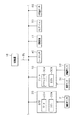
図1に示すように、制御装置10は、CPU、ROM、RAM、及びI/O等を備えるコンピュータであり、CPUが、ROMにインストールされているプログラムを実行することで各種制御を行う。制御装置10は、通信線SLに接続された各装置との間で、CAN等の予め設定された通信プロトコルに従ってデータの送受信を行う。
As illustrated in FIG. 1, the
車両は、電動パワーステアリング装置20、ブレーキ装置30、車両の操舵輪の操舵角を検出する操舵角センサ21、自車両の走行速度を検出する車速センサ31、自車両の車輪の回転速度を検出する車輪速センサ32、及び自車両の周囲の外気温度を検出する外気温センサ60を備えている。
The vehicle detects an electric
電動パワーステアリング装置20は、ステアリングに操舵力を付与するステアリングモータ20aと、ステアリングECU20bとを備えている。ステアリングECU20bは、ドライバのステアリング操作時において、操舵角センサ21により検出された操舵角に基づいて、ステアリングモータ20aにより操舵輪の操舵角変更時のアシスト力を発生するパワーステアリング制御を実行する。
The electric
またステアリングECU20bは、制御装置10から通信線SLを介して送信されるステアリング制御信号に基づいて、衝突回避制御として、ドライバのステアリング操作なしでステアリングモータ20aにより自動的に操舵角を制御する自動操舵制御を行う。
Further, the
ブレーキ装置30は、マスタシリンダの油圧を調整するブレーキアクチュエータ30aと、ブレーキECU30bとを備えている。ブレーキECU30bは、マスタシリンダの油圧、車速センサ31により検出された自車両の走行速度である自車速、及び車輪速センサ32により検出された車輪の回転速度に基づいて、ブレーキアクチュエータ30aによりABS制御やトラクション制御等を行う。ABS制御は、各車輪の回転方向での滑り量を示すスリップ率を適正に保つためになされる制動制御である。スリップ率は、例えば、車速センサ31により検出された自車速と、車輪速センサ32により検出された車輪の回転速度とに基づいて算出されればよい。
The
またブレーキECU30bは、制御装置10から通信線SLを介して送信される制動制御信号に基づいて、衝突回避制御として、ドライバのブレーキ操作なしでブレーキアクチュエータ30aにより自動的に車輪に制動力を付与する自動制動制御を行う。
The
車両は、レーダセンサ40を備えている。レーダセンサ40は、ミリ波やレーザ等の指向性のある電磁波を利用して自車両の前方の物体を検出するものであり、例えば、自車両の前部においてその光軸が車両前方を向くように取り付けられている。レーダセンサ40は、所定時間ごとに自車両前方に向かって所定範囲で広がる領域をレーダ信号で走査するとともに、前方物体の表面で反射された電磁波を受信することで前方物体との距離、及び前方物体との相対速度等を物体情報として取得する。具体的には、物体情報には、自車両の進行方向における前方物体との距離、及び自車両の進行方向における前方物体との相対速度が含まれる。取得された物体情報は、制御装置10に入力される。
The vehicle includes a
車両は、撮像装置41を備えている。撮像装置41は車載カメラであり、CCDカメラやCMOSイメージセンサ、近赤外線カメラ等で構成されている。撮像装置41は、自車両の走行道路を含む周辺環境を撮影する。撮像装置41は、自車両の例えばフロントガラスの上端付近に取り付けられており、撮像軸を中心に車両前方に向かって所定の撮影角度の範囲で広がる領域を撮影する。なお、撮像装置41は、単眼カメラであってもよいし、ステレオカメラであってもよい。
The vehicle includes an
撮像装置41は、撮影した画像を表す画像データを生成して制御装置10に逐次出力する。制御装置10は、入力された画像データに基づいて、自車線を区画する区画線等、自車両の前方における左右方向それぞれに位置する境界線を認識する。
The
車両は、ナビゲーション装置50を備えている。ナビゲーション装置50は、道路地図データ及び各種情報を記録した地図記憶媒体から地図データを取得するとともに、GPSアンテナを介して受信したGPS信号等に基づいて、自車両の現在位置を算出する。またナビゲーション装置50は、自車両の現在地を表示画面に表示するための制御、及び現在地から目的地までの経路を案内するための制御等を行う。
The vehicle includes a
続いて図2を用いて、本実施形態に係る衝突回避制御処理について説明する。この処理は、制御装置10により、例えば所定の処理周期(例えば50ms)で繰り返し実行される。
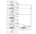
Next, the collision avoidance control process according to the present embodiment will be described with reference to FIG. This process is repeatedly executed by the
この一連の処理では、まずステップS10において、自車両の前方に物体が存在しているか否かを判定する。ここで前方に物体が存在しているか否かは、例えばレーダセンサ40から取得した物体情報に基づいて判定されればよい。
In this series of processing, first, in step S10, it is determined whether or not an object exists in front of the host vehicle. Here, whether or not an object is present ahead may be determined based on, for example, object information acquired from the
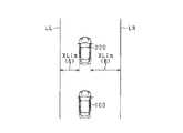
ステップS10において物体が存在していると判定した場合には、ステップS12に進み、前方物体と自車両との衝突可能性があるか否かを判定する。本実施形態において、ステップS12の処理が衝突判定部に相当する。本実施形態では、レーダセンサ40から取得した物体情報又は撮像装置41から取得した画像に基づいて、前方物体の左右方向端部のそれぞれの横位置を取得する。そして取得した横位置に基づいてラップ率Laを算出し、算出したラップ率Laが判定閾値以上であると判定した場合、衝突可能性があると判定する。本実施形態において、ラップ率Laは、図3に示すように、自車両100の幅をXwとし、自車両100の幅と前方物体200の幅とが重複する領域の幅をXlとすると、下式(1)で求められるパラメータである。
If it is determined in step S10 that an object exists, the process proceeds to step S12, and it is determined whether or not there is a possibility of collision between the front object and the host vehicle. In the present embodiment, the process in step S12 corresponds to a collision determination unit. In this embodiment, based on the object information acquired from the
La=Xl/Xw・・・(1)
なお、前方物体と自車両との衝突可能性があるか否かの判定手法としては、上述した手法に限らず、例えば、特開2015−232825号公報の図4に記載された手法を用いてもよい。
La = Xl / Xw (1)
Note that the method for determining whether or not there is a possibility of collision between the front object and the host vehicle is not limited to the above-described method, and for example, using the method described in FIG. 4 of JP-A-2015-232825. Also good.
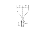
ステップS12において衝突可能性があると判定した場合には、ステップS14に進み、自車両と前方物体との衝突までの時間である衝突予測時間TTC(Time To Collision)を算出する。衝突予測時間TTCは、例えば、図3に示すように、レーダセンサ40から取得した自車両100の進行方向における前方物体200との距離Lyと、自車両100の進行方向における前方物体200との相対速度とに基づいて算出されればよい。
If it is determined in step S12 that there is a possibility of a collision, the process proceeds to step S14, and a collision prediction time TTC (Time To Collision) that is a time until the collision between the host vehicle and the front object is calculated. For example, as shown in FIG. 3, the predicted collision time TTC is a relative value between the distance Ly from the
続くステップS16では、算出した衝突予測時間TTCが閾値時間TTα以下であるか否かを判定する。この処理は、衝突回避制御を実行するか否かを判定するための処理である。なお閾値時間TTαは、自車両の進行方向における自車両と前方物体との相対速度に基づいて、可変設定されればよい。 In subsequent step S16, it is determined whether or not the calculated collision predicted time TTC is equal to or shorter than the threshold time TTα. This process is a process for determining whether to execute the collision avoidance control. The threshold time TTα may be variably set based on the relative speed between the host vehicle and the front object in the traveling direction of the host vehicle.
ステップS16において肯定判定した場合には、ステップS18に進み、衝突回避制御としてブレーキ装置30による自動制動制御を実行する。続くステップS20では、外気温センサ60により検出された外気温度Tempを取得する。なお本実施形態において、ステップS20の処理が温度取得部に相当する。
When an affirmative determination is made in step S16, the process proceeds to step S18, and automatic braking control by the
続くステップS22では、取得した外気温度Tempが所定温度Tth(例えば−4℃)以下であるか否かを判定する。本実施形態において、所定温度Tthは、路面が凍結すると想定される温度に設定され、具体的には、氷点下の温度(例えば−4℃)に設定されている。ステップS22の処理は、自車両の走行路面が低μ路であるか否かを判定するための処理であり、本実施形態において路面判定部に相当する。 In a succeeding step S22, it is determined whether or not the acquired outside air temperature Temp is equal to or lower than a predetermined temperature Tth (for example, −4 ° C.). In the present embodiment, the predetermined temperature Tth is set to a temperature at which the road surface is assumed to be frozen, and specifically, set to a temperature below the freezing point (for example, −4 ° C.). The process of step S22 is a process for determining whether or not the traveling road surface of the host vehicle is a low μ road, and corresponds to a road surface determination unit in the present embodiment.
ステップS22において外気温度Tempが所定温度Tthよりも高いと判定した場合には、ステップS24に進み、電動パワーステアリング装置20による自動操舵制御の実行を許可する。
If it is determined in step S22 that the outside air temperature Temp is higher than the predetermined temperature Tth, the process proceeds to step S24, and execution of automatic steering control by the electric
なお、衝突回避制御として自動操作制御を実行するか否かは、衝突予測時間TTC、及び自車両の進行方向における自車両と前方物体との相対速度から定まる動作点に基づいて判定される。この判定手法については、例えば特開2015−232825号公報の図6に記載されているため、その詳細な説明を省略する。 Whether or not the automatic operation control is executed as the collision avoidance control is determined based on the collision prediction time TTC and the operating point determined from the relative speed between the host vehicle and the forward object in the traveling direction of the host vehicle. Since this determination method is described in FIG. 6 of JP-A-2015-232825, for example, detailed description thereof is omitted.
一方、ステップS22において外気温度Tempが所定温度Tth以下であると判定した場合には、自車両の走行路面が低μ路であると判定し、ステップS26に進む。ステップS26では、自動操舵制御の実行を禁止する。これにより、自動操舵制御の実行により自車両がスリップ等の不安定挙動を呈することを防止する。 On the other hand, when it is determined in step S22 that the outside air temperature Temp is equal to or lower than the predetermined temperature Tth, it is determined that the traveling road surface of the host vehicle is a low μ road, and the process proceeds to step S26. In step S26, execution of automatic steering control is prohibited. This prevents the host vehicle from exhibiting unstable behavior such as slip due to execution of automatic steering control.
以上説明したように、本実施形態では、外気温度Tempが所定温度Tth以下であると判定された場合、衝突回避制御として自動操舵制御が実行されることを禁止した。このため、自車両と前方物体との衝突可能性がある場合における衝突回避制御時に、自動操舵制御の実行により自車両が不安定挙動を呈することを防止できる。 As described above, in the present embodiment, when it is determined that the outside air temperature Temp is equal to or lower than the predetermined temperature Tth, the automatic steering control is prohibited from being executed as the collision avoidance control. For this reason, at the time of collision avoidance control when there is a possibility of collision between the host vehicle and a front object, it is possible to prevent the host vehicle from exhibiting unstable behavior due to execution of automatic steering control.
(第2実施形態)
以下、第2実施形態について、上記第1実施形態との相違点を中心に図面を参照しつつ説明する。本実施形態では、自車両の走行路面が低μ路であるか否かの判定手法を変更する。
(Second Embodiment)
Hereinafter, the second embodiment will be described with reference to the drawings with a focus on differences from the first embodiment. In the present embodiment, a method for determining whether or not the traveling road surface of the host vehicle is a low μ road is changed.
図4に、本実施形態に係る衝突回避制御処理の手順を示す。この処理は、制御装置10により、例えば所定の処理周期で繰り返し実行される。なお図4において、先の図2に示した処理と同一の処理については、便宜上、同一の符号を付している。
FIG. 4 shows the procedure of the collision avoidance control process according to this embodiment. This processing is repeatedly executed by the
この一連の処理では、ステップS18の処理の後、ステップS30において、自車両の走行経路の属する地域の降雪情報を取得する処理を行う。ここで降雪情報は、無線通信を介してナビゲーション装置50により取得すればよい。なお本実施形態において、ステップS30の処理が情報取得部に相当する。
In this series of processes, after the process of step S18, in step S30, a process of acquiring snowfall information of an area to which the traveling route of the host vehicle belongs is performed. Here, the snowfall information may be acquired by the
続くステップS32では、ステップS30において降雪情報が取得されたか否かを判定する。ステップS32において降雪情報が取得されなかったと判定した場合には、ステップS24に進む。一方、ステップS32において降雪情報が取得されたと判定した場合には、自動操舵制御により自車両が不安定挙動を呈するおそれがあると判定し、ステップS26において自動操舵制御の実行を禁止する。 In continuing step S32, it is determined whether snowfall information was acquired in step S30. If it is determined in step S32 that the snowfall information has not been acquired, the process proceeds to step S24. On the other hand, if it is determined in step S32 that snowfall information has been acquired, it is determined that there is a risk that the host vehicle will exhibit unstable behavior by automatic steering control, and execution of automatic steering control is prohibited in step S26.
以上説明した本実施形態によっても、上記第1実施形態と同様の効果を奏することができる。 According to the present embodiment described above, the same effects as those of the first embodiment can be obtained.
(第3実施形態)
以下、第3実施形態について、上記第1実施形態との相違点を中心に図面を参照しつつ説明する。本実施形態では、自動操舵制御の禁止手法を変更する。
(Third embodiment)
Hereinafter, the third embodiment will be described with reference to the drawings with a focus on differences from the first embodiment. In this embodiment, the method for prohibiting automatic steering control is changed.
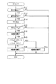
図5に、本実施形態に係る衝突回避制御処理の手順を示す。この処理は、制御装置10により、例えば所定の処理周期で繰り返し実行される。なお図5において、先の図2に示した処理と同一の処理については、便宜上、同一の符号を付している。
FIG. 5 shows the procedure of the collision avoidance control process according to this embodiment. This processing is repeatedly executed by the
この一連の処理では、ステップS18の処理の後、ステップS40において、横方向回避量Xadの絶対値がフリースペース幅XLim以下であるとの第1条件と、横方向回避量Xadの絶対値がその最大回避量Xb以下であるとの第2条件との論理積が真であるか否かを判定する。本実施形態において、ステップS40の処理が回避量算出部及び最大値算出部を含む。ステップS40の処理は、自動操舵制御の実行を禁止するか否かを判定するための処理である。 In this series of processing, after the processing of step S18, in step S40, the first condition that the absolute value of the lateral avoidance amount Xad is equal to or less than the free space width XLim and the absolute value of the lateral avoidance amount Xad are It is determined whether the logical product of the second condition that the maximum avoidance amount Xb is equal to or less than the maximum avoidance amount Xb is true. In the present embodiment, the process of step S40 includes an avoidance amount calculation unit and a maximum value calculation unit. The process of step S40 is a process for determining whether or not execution of automatic steering control is prohibited.
第1条件において、横方向回避量Xadは、自車両の進行方向に直交する左右方向の移動量であって、前方物体と自車両との衝突可能性を無くすために必要な移動量である。以下、図6を用いて、横方向回避量Xadの算出手法の一例について説明する。 In the first condition, the lateral avoidance amount Xad is a movement amount in the left-right direction orthogonal to the traveling direction of the host vehicle, and is a movement amount necessary to eliminate the possibility of a collision between the front object and the host vehicle. Hereinafter, an example of a method of calculating the lateral avoidance amount Xad will be described with reference to FIG.
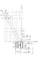
まず、図6に示すように、自車両100の進行方向に延びる座標軸をY軸とし、Y軸と直交してかつ自車両の左右方向に延びる座標軸をX軸とする2次元直交座標系を定義する。そして、この座標系の原点O(0,0)を、自車両100の前端中央部に一致させる。
First, as shown in FIG. 6, a two-dimensional orthogonal coordinate system is defined in which the coordinate axis extending in the traveling direction of the
自車両100の幅をXwとし、自車両100の全長をLとすると、(Xw/2,0)で規定される第1座標点P1、(Xw/2,−L)で規定される第2座標点P2、(−Xw/2,0)で規定される第3座標点P3、及び(−Xw/2,−L)で規定される第4座標点P4を頂点とする長方形領域にて、自車両100の存在範囲が定められる。以下、この長方形領域を自車両領域RSと称すこととする。
If the width of the
前回の処理周期においてレーダセンサ40から取得した物体情報と、今回の処理周期においてレーダセンサ40から取得した物体情報とに基づいて、自車両100から前方物体200を見た場合における前方物体200の自車両100側における右端部及び左端部のそれぞれの相対速度ベクトルを算出する。具体的には、前回の処理周期における前方物体200の自車両100側における右端部,左端部の位置を第4座標点P4,第5座標点P5とし、今回の処理周期における前方物体200の自車両100側における右端部,左端部の位置を第6座標点P6,第7座標点P7とする。そして、前方物体200の右端部の相対速度ベクトルV1を、第6座標点P6の座標値から第4座標点P4の座標値を減算することにより算出する。同様に、前方物体200の左端部の相対速度ベクトルV2を、第7座標点P7の座標値から第5座標点P5の座標値を減算することにより算出する。
Based on the object information acquired from the
そして、前方物体200の右端部の今回位置を示す第6座標点P6を起点とした相対速度ベクトルV1の延長線である第1延長線EL1と、前方物体200の左端部を起点とした相対速度ベクトルV2の延長線である第2延長線EL2とを算出する。そして、第1,第2延長線EL1,EL2と自車両領域RSとが交差しなくなるまでに必要となるX軸方向の自車両領域RSの移動量として、横方向回避量Xadを算出する。
Then, the first extension line EL1 that is an extension line of the relative velocity vector V1 starting from the sixth coordinate point P6 indicating the current position of the right end portion of the
第1条件において、フリースペース幅XLimは、自車両の進行方向に対して前方物体の左右方向に存在する退避スペースの幅である。本実施形態では、レーダセンサ40や撮像装置41から取得した情報に基づいて、前方物体の左右方向のそれぞれのフリースペース幅XLimを算出する。図7には、自車両100の前方に存在する左右の境界線LL,LRと先行車両としての前方物体200との間に存在する左右のフリースペース幅XLimを例示した。
In the first condition, the free space width XLim is the width of the retreat space that exists in the left-right direction of the front object with respect to the traveling direction of the host vehicle. In the present embodiment, based on information acquired from the
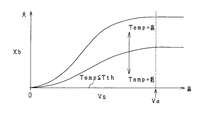
一方、第2条件において、最大回避量Xbは、図8に示すように、自動操舵制御により可能となる自車両100の横方向回避量の最大値であり、自車速Vsに依存する。本実施形態では、図9に示すように、自車速Vsが高いほど、最大回避量Xbを大きく設定する。具体的には、自車速Vsが0から所定速度Vαまでの速度範囲となる場合において、自車速Vsが高いほど最大回避量Xbを大きく設定し、自車速Vsが上記速度範囲以上となる場合において、最大回避量Xbを自車速Vsが所定速度Vαとなるときの値に固定する。
On the other hand, under the second condition, as shown in FIG. 8, the maximum avoidance amount Xb is the maximum value of the lateral avoidance amount of the
ここで本実施形態では、外気温度Tempに基づいて最大回避量Xbを補正する。本実施形態では、外気温度Tempが低いほど、最大回避量Xbを小さくする。特に本実施形態では、外気温度Tempが所定温度Tth以下であると判定した場合、最大回避量Xbを0とする。 Here, in the present embodiment, the maximum avoidance amount Xb is corrected based on the outside air temperature Temp. In the present embodiment, the lower the outside air temperature Temp, the smaller the maximum avoidance amount Xb. In particular, in this embodiment, when it is determined that the outside air temperature Temp is equal to or lower than the predetermined temperature Tth, the maximum avoidance amount Xb is set to zero.
最大回避量Xbが0にされると、ステップS40において上記第2条件が成立しなくなる。これにより、ステップS40において否定判定され、ステップS26において自動操舵制御の実行が禁止される。このように、以上説明した本実施形態によっても、上記第1実施形態と同様の効果を奏することができる。 When the maximum avoidance amount Xb is set to 0, the second condition is not satisfied in step S40. Thus, a negative determination is made in step S40, and execution of automatic steering control is prohibited in step S26. Thus, also by this embodiment described above, the same effects as those of the first embodiment can be obtained.
(第4実施形態)
以下、第4実施形態について、上記第1実施形態との相違点を中心に図面を参照しつつ説明する。本実施形態では、自車両の走行路面が低μ路であるか否かの判定手法を変更する。
(Fourth embodiment)
Hereinafter, the fourth embodiment will be described with reference to the drawings with a focus on differences from the first embodiment. In the present embodiment, a method for determining whether or not the traveling road surface of the host vehicle is a low μ road is changed.
図10に、本実施形態に係る衝突回避制御処理の手順を示す。この処理は、制御装置10により、例えば所定の処理周期で繰り返し実行される。なお図10において、先の図2に示した処理と同一の処理については、便宜上、同一の符号を付している。
FIG. 10 shows the procedure of the collision avoidance control process according to this embodiment. This processing is repeatedly executed by the
この一連の処理では、ステップS18の処理の後、ステップS50において、車輪がスリップしているか否かを判定する。本実施形態では、ABS制御が実行されていることを示すABSフラグFabsの値に基づいて、スリップが発生しているか否かを判定する。 In this series of processes, after the process of step S18, it is determined in step S50 whether or not the wheel is slipping. In the present embodiment, it is determined whether or not slip has occurred based on the value of the ABS flag Fabs indicating that the ABS control is being executed.
ステップS50においてスリップが発生していないと判定した場合には、ステップS24に進む。一方、ステップS50においてスリップが発生していると判定した場合には、ステップS26において自動操舵制御の実行が禁止される。 If it is determined in step S50 that no slip has occurred, the process proceeds to step S24. On the other hand, when it is determined in step S50 that slip has occurred, execution of automatic steering control is prohibited in step S26.
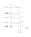
図11に、先の図10のステップS12で肯定判定される状況における衝突回避制御の一例を示す。ここで、図11(a)は衝突予測時間TTCの推移を示し、図11(b)は自動制動制御の実施状況の推移を示し、図11(c)は実際のスリップの発生状況の推移を示す。また、図11(d)はABSフラグFabsの推移を示し、図11(e)は自動操舵制御が禁止されているか否かの推移を示す。なお、ABSフラグFabsは、1によってABS制御が実行されていることを示し、0によってABS制御が実行されていないことを示す。 FIG. 11 shows an example of collision avoidance control in the situation where an affirmative determination is made in step S12 of FIG. Here, FIG. 11 (a) shows the transition of the predicted collision time TTC, FIG. 11 (b) shows the transition of the implementation status of the automatic braking control, and FIG. 11 (c) shows the transition of the actual slip occurrence status. Show. FIG. 11D shows the transition of the ABS flag Fabs, and FIG. 11E shows the transition of whether or not automatic steering control is prohibited. The ABS flag Fabs indicates that ABS control is being executed by 1 and that ABS control is not being executed by 0.
図示される例では、時刻T1において、衝突予測時間TTCが閾値時間TTα以下になると判定される。このため、衝突回避制御として自動制動制御が開始される。 In the illustrated example, at time T1, it is determined that the collision prediction time TTC is equal to or less than the threshold time TTα. For this reason, automatic braking control is started as collision avoidance control.
その後、自動制動制御の実行により、時刻T2において車輪がスリップする。このため、ABS制御が開始され、ABSフラグFabsの値が0から1に切り替えられる。これにより、スリップが発生していると判定され、衝突回避制御としての自動操舵制御の実行が禁止される。 Thereafter, the wheel slips at time T2 due to execution of automatic braking control. Therefore, ABS control is started and the value of the ABS flag Fabs is switched from 0 to 1. As a result, it is determined that slip has occurred, and execution of automatic steering control as collision avoidance control is prohibited.
以上説明した本実施形態によれば、自動制動制御が開始されたことに起因して実際に発生するスリップを的確に検知して、自動操舵制御の実行を禁止することができる。なお、自動制動制御の開始後「T2−T1」だけ必ず遅れて自動操舵制御を実行するようあらかじめプログラムするように設定してもよい。この遅れの設定により、確実に低μ路判定がなされたことを担保した上で自動操舵制御を行うか否かを判定することができる。 According to the present embodiment described above, it is possible to accurately detect a slip that actually occurs due to the start of the automatic braking control and to prohibit the execution of the automatic steering control. Note that it may be set to be programmed in advance so as to execute the automatic steering control with a delay of “T2-T1” after the start of the automatic braking control. By setting this delay, it is possible to determine whether or not to perform automatic steering control while ensuring that the low μ road determination has been made.
(その他の実施形態)
なお、上記各実施形態は、以下のように変更して実施してもよい。
(Other embodiments)
Each of the above embodiments may be modified as follows.
・自車両の走行路面が低μ路であるか否かの判定手法としては、上記各実施形態に例示したものに限らない。例えば、外気温度Tempが所定温度Tth以下であるとの条件と、降雪情報が取得されているとの条件との論理積が真であると判定された場合、低μ路であると判定してもよい。 The method for determining whether the traveling road surface of the host vehicle is a low μ road is not limited to those exemplified in the above embodiments. For example, when it is determined that the logical product of the condition that the outside air temperature Temp is equal to or lower than the predetermined temperature Tth and the condition that the snowfall information is acquired is true, it is determined that the road is a low μ road. Also good.
・上記第1実施形態において、図2のステップS22で用いる外気温度Tempとして、外気温センサ60の検出値に代えて、無線通信を介してナビゲーション装置50により取得された自車両の走行経路の属する地域の温度情報を用いてもよい。
In the first embodiment, the outside air temperature Temp used in step S22 of FIG. 2 belongs to the travel route of the host vehicle acquired by the
・上記第2実施形態において、図4のステップS32で用いる降雪情報として、ドライバの手動入力による降雪情報を用いてもよい。この降雪情報は、例えば、ナビゲーション装置50のタッチパネル式の表示部に表示された降雪情報ボタンがドライバに押されることにより入力されればよい。
-In the said 2nd Embodiment, you may use the snowfall information by a driver | operator's manual input as snowfall information used by step S32 of FIG. This snowfall information may be input by, for example, pressing a snowfall information button displayed on the touch panel display unit of the
・上記第3実施形態における図5のステップS40の処理において、自車両の横方向加速度をさらに用いて最大回避量Xbを補正してもよい。これは、例えば、自車両がカーブを走行する場合に有効である。 In the process of step S40 of FIG. 5 in the third embodiment, the maximum avoidance amount Xb may be corrected by further using the lateral acceleration of the host vehicle. This is effective, for example, when the host vehicle travels on a curve.
またステップS40において、降雪情報が取得されたと判定された場合、最大回避量Xbが0に設定されてもよい。さらにステップS40において、外気温度Tempが所定温度Tth以下であると判定された場合、最大回避量Xbが、0よりも大きくて、かつ、横方向回避量Xadの絶対値として想定される最小値よりも小さい値に設定されてもよい。 In Step S40, when it is determined that snowfall information has been acquired, the maximum avoidance amount Xb may be set to zero. Further, when it is determined in step S40 that the outside air temperature Temp is equal to or lower than the predetermined temperature Tth, the maximum avoidance amount Xb is larger than 0 and is less than the minimum value assumed as the absolute value of the lateral direction avoidance amount Xad. May be set to a small value.
・上記各実施形態において、車両からレーダセンサ40を除去し、レーダセンサ40の役割を撮像装置41に担わせてもよい。
In each of the above embodiments, the
10…制御装置、20…電動パワーステアリング装置、30…ブレーキ装置、40…レーダセンサ。
DESCRIPTION OF
Claims (5)
前記衝突判定部により衝突可能性有りと判定された場合、前記自車両と前記物体との衝突を回避するための衝突回避制御として前記自車両を操舵する自動操舵制御を実行する制御部と、
前記自車両の走行路面が低μ路であるか否かを判定する処理を行う路面判定部と、を備え、
前記制御部は、前記路面判定部により低μ路であると判定された場合、前記自動操舵制御の実行を禁止する車両制御装置(10)。 A collision determination unit that determines the possibility of collision between the host vehicle and an object existing in front of the vehicle;
A controller that performs automatic steering control for steering the host vehicle as collision avoidance control for avoiding a collision between the host vehicle and the object when the collision determination unit determines that there is a collision possibility;
A road surface determination unit that performs a process of determining whether or not the traveling road surface of the host vehicle is a low μ road,
The control unit (10) prohibits execution of the automatic steering control when the road surface determination unit determines that the road surface is a low μ road.
前記路面判定部は、前記判定する処理として、前記温度取得部により取得された外気温度が所定温度以下であるか否かを判定する処理を行い、
前記制御部は、前記路面判定部により外気温度が前記所定温度以下であると判定された場合、前記自動操舵制御の実行を禁止する請求項1に記載の車両制御装置。 A temperature acquisition unit for acquiring the ambient temperature around the host vehicle;
The road surface determination unit performs a process of determining whether or not the outside air temperature acquired by the temperature acquisition unit is a predetermined temperature or less as the determination process,
The vehicle control device according to claim 1, wherein the control unit prohibits execution of the automatic steering control when the road surface determination unit determines that an outside air temperature is equal to or lower than the predetermined temperature.
前記路面判定部は、前記判定する処理として、前記情報取得部により降雪情報が取得されたか否かを判定する処理を行い、
前記制御部は、前記路面判定部により前記降雪情報が取得されたと判定された場合、前記自動操舵制御の実行を禁止する請求項1又は2に記載の車両制御装置。 An information acquisition unit for acquiring snowfall information of a region to which the traveling route of the host vehicle belongs,
The road surface determination unit performs a process of determining whether or not snow information is acquired by the information acquisition unit as the determination process,
The vehicle control device according to claim 1, wherein the control unit prohibits execution of the automatic steering control when it is determined that the snowfall information is acquired by the road surface determination unit.
前記衝突判定部により衝突可能性有りと判定された場合、前記物体との衝突を回避するために要する前記自車両の横方向回避量を算出する回避量算出部と、
前記自車両の走行速度に基づいて、前記自動操舵制御により可能となる前記自車両の横方向回避量の最大値を算出する最大値算出部と、を含み、前記横方向回避量が前記最大値以下であることを条件として、前記自動操舵制御を実行し、
前記最大値算出部は、前記路面判定部により低μ路であると判定された場合に、前記路面判定部により低μ路でないと判定された場合に比べて、前記最大値を小さい値にする請求項1〜3のいずれか1項に記載の車両制御装置。 The controller is
An avoidance amount calculation unit that calculates a lateral avoidance amount of the host vehicle required to avoid a collision with the object when the collision determination unit determines that there is a collision possibility;
A maximum value calculation unit that calculates a maximum value of the lateral avoidance amount of the host vehicle that is enabled by the automatic steering control based on the traveling speed of the host vehicle, and the lateral avoidance amount is the maximum value The automatic steering control is executed on condition that:
The maximum value calculation unit makes the maximum value smaller when the road surface determination unit determines that the road is a low μ road than when the road surface determination unit determines that the road is not a low μ road. The vehicle control device according to any one of claims 1 to 3.
前記路面判定部は、前記判定する処理として、前記自動制動制御の実行により前記自車両のスリップが発生しているか否かを判定する処理を行い、
前記制御部は、前記自動制動制御の開始後において、前記路面判定部によりスリップが発生していると判定されない場合に前記自動操舵制御の実行を許可し、前記路面判定部によりスリップが発生していると判定された場合に前記自動操舵制御の実行を禁止する請求項1〜4のいずれか1項に記載の車両制御装置。 When the collision determination unit determines that there is a possibility of collision, the control unit performs automatic braking control that applies a braking force to the host vehicle as the collision avoidance control,
The road surface determination unit performs a process of determining whether or not a slip of the host vehicle has occurred due to the execution of the automatic braking control as the determination process,
The control unit permits execution of the automatic steering control when the road surface determination unit does not determine that a slip has occurred after the start of the automatic braking control, and the road surface determination unit generates a slip. The vehicle control device according to any one of claims 1 to 4, wherein execution of the automatic steering control is prohibited when it is determined that the vehicle is present.
Priority Applications (5)
| Application Number | Priority Date | Filing Date | Title |
|---|---|---|---|
| JP2016079121A JP6460033B2 (en) | 2016-04-11 | 2016-04-11 | Vehicle control device |
| PCT/JP2017/014527 WO2017179505A1 (en) | 2016-04-11 | 2017-04-07 | Vehicle control device |
| DE112017001962.1T DE112017001962T5 (en) | 2016-04-11 | 2017-04-07 | Vehicle control apparatus |
| CN201780022604.8A CN108885840A (en) | 2016-04-11 | 2017-04-07 | Controller of vehicle |
| US16/092,344 US20190143966A1 (en) | 2016-04-11 | 2017-04-07 | Vehicle control apparatus |
Applications Claiming Priority (1)
| Application Number | Priority Date | Filing Date | Title |
|---|---|---|---|
| JP2016079121A JP6460033B2 (en) | 2016-04-11 | 2016-04-11 | Vehicle control device |
Publications (3)
| Publication Number | Publication Date |
|---|---|
| JP2017191383A true JP2017191383A (en) | 2017-10-19 |
| JP2017191383A5 JP2017191383A5 (en) | 2018-03-29 |
| JP6460033B2 JP6460033B2 (en) | 2019-01-30 |
Family
ID=60042415
Family Applications (1)
| Application Number | Title | Priority Date | Filing Date |
|---|---|---|---|
| JP2016079121A Active JP6460033B2 (en) | 2016-04-11 | 2016-04-11 | Vehicle control device |
Country Status (5)
| Country | Link |
|---|---|
| US (1) | US20190143966A1 (en) |
| JP (1) | JP6460033B2 (en) |
| CN (1) | CN108885840A (en) |
| DE (1) | DE112017001962T5 (en) |
| WO (1) | WO2017179505A1 (en) |
Cited By (1)
| Publication number | Priority date | Publication date | Assignee | Title |
|---|---|---|---|---|
| CN110040134A (en) * | 2019-03-13 | 2019-07-23 | 重庆邮电大学 | Consider the vehicle collision time calculation method of environmental factor |
Families Citing this family (2)
| Publication number | Priority date | Publication date | Assignee | Title |
|---|---|---|---|---|
| CN110403781B (en) * | 2019-08-08 | 2021-02-09 | 山东大学 | Hospital bed pivot turning control system and control method |
| JP2022159668A (en) * | 2021-04-05 | 2022-10-18 | トヨタ自動車株式会社 | Vehicle collision avoidance support device |
Citations (4)
| Publication number | Priority date | Publication date | Assignee | Title |
|---|---|---|---|---|
| JP2000006787A (en) * | 1998-06-18 | 2000-01-11 | Nissan Motor Co Ltd | Traveling controller for vehicle |
| JP2010198533A (en) * | 2009-02-27 | 2010-09-09 | Nissan Motor Co Ltd | Road surface information providing device and road surface state determining method |
| JP2015154632A (en) * | 2014-02-17 | 2015-08-24 | トヨタ自動車株式会社 | electric vehicle |
| JP2015232825A (en) * | 2014-06-10 | 2015-12-24 | 株式会社デンソー | Collision avoidance system |
Family Cites Families (26)
| Publication number | Priority date | Publication date | Assignee | Title |
|---|---|---|---|---|
| JPH0558319A (en) | 1991-08-27 | 1993-03-09 | Mazda Motor Corp | Contact preventive device for vehicle |
| DE19650475C1 (en) * | 1996-12-05 | 1998-04-16 | Daimler Benz Ag | Motor vehicle steering system |
| JP3319984B2 (en) * | 1997-07-09 | 2002-09-03 | 本田技研工業株式会社 | Vehicle collision avoidance device |
| JP3525872B2 (en) * | 2000-08-01 | 2004-05-10 | トヨタ自動車株式会社 | Automatic steering device for vehicles |
| JP4169065B2 (en) * | 2006-02-13 | 2008-10-22 | 株式会社デンソー | Vehicle control device |
| US7599774B2 (en) * | 2006-03-10 | 2009-10-06 | Gm Global Technology Operations, Inc. | Method and system for adaptively compensating closed-loop front-wheel steering control |
| JP4980076B2 (en) * | 2007-01-11 | 2012-07-18 | 富士重工業株式会社 | Vehicle driving support device |
| EP2085279B1 (en) * | 2008-01-29 | 2011-05-25 | Ford Global Technologies, LLC | A system for collision course prediction |
| DE102009046966B4 (en) * | 2009-11-23 | 2019-01-31 | Robert Bosch Gmbh | Method for assisting the driver of a vehicle |
| DE102010032929A1 (en) * | 2010-07-30 | 2012-02-02 | Lucas Automotive Gmbh | Method for operating an electrically controllable brake system |
| US8527172B2 (en) * | 2010-10-20 | 2013-09-03 | GM Global Technology Operations LLC | Vehicle collision avoidance and warning system |
| EP2681085B1 (en) * | 2011-03-01 | 2017-05-10 | Continental Teves AG & Co. oHG | Method and device for the prediction and adaptation of movement trajectories of motor vehicles |
| US20130030651A1 (en) * | 2011-07-25 | 2013-01-31 | GM Global Technology Operations LLC | Collision avoidance maneuver through differential braking |
| JP5796632B2 (en) * | 2011-09-26 | 2015-10-21 | トヨタ自動車株式会社 | Vehicle driving support system |
| US9674490B2 (en) * | 2013-04-18 | 2017-06-06 | Magna Electronics Inc. | Vision system for vehicle with adjustable cameras |
| DE112013007255T5 (en) * | 2013-07-19 | 2016-03-31 | Honda Motor Co., Ltd. | Vehicle Ride Safety Device, Vehicle Ride Safety Procedure and Vehicle Ride Safety Program |
| US20150100191A1 (en) * | 2013-10-09 | 2015-04-09 | Ford Global Technologies, Llc | Monitoring autonomous vehicle steering |
| JP2016079121A (en) | 2014-10-15 | 2016-05-16 | 石原産業株式会社 | Heteroaryl sulfonamide compound and herbicide comprising the same |
| KR102350043B1 (en) * | 2015-11-20 | 2022-01-12 | 주식회사 만도 | System and method for controlling autonomous steering |
| US10435016B2 (en) * | 2016-05-15 | 2019-10-08 | Mechanical Simulation Corporation | System and method to stabilize motorcycles |
| WO2017213119A1 (en) * | 2016-06-06 | 2017-12-14 | 日本精工株式会社 | Electric power steering device |
| US10351168B2 (en) * | 2016-07-28 | 2019-07-16 | Nsk Ltd. | Electric power steering apparatus |
| JP6601345B2 (en) * | 2016-08-24 | 2019-11-06 | 株式会社デンソー | Vehicle control device |
| EP3299993A1 (en) * | 2016-09-22 | 2018-03-28 | OmniKlima AB | Method and arrangement for determining a condition of a road surface |
| US20180217050A1 (en) * | 2017-01-30 | 2018-08-02 | GM Global Technology Operations LLC | Invasive active dynamic tests to determine surface coefficient of friction |
| US11260875B2 (en) * | 2017-12-07 | 2022-03-01 | Uatc, Llc | Systems and methods for road surface dependent motion planning |
-
2016
- 2016-04-11 JP JP2016079121A patent/JP6460033B2/en active Active
-
2017
- 2017-04-07 US US16/092,344 patent/US20190143966A1/en not_active Abandoned
- 2017-04-07 WO PCT/JP2017/014527 patent/WO2017179505A1/en active Application Filing
- 2017-04-07 DE DE112017001962.1T patent/DE112017001962T5/en not_active Ceased
- 2017-04-07 CN CN201780022604.8A patent/CN108885840A/en active Pending
Patent Citations (4)
| Publication number | Priority date | Publication date | Assignee | Title |
|---|---|---|---|---|
| JP2000006787A (en) * | 1998-06-18 | 2000-01-11 | Nissan Motor Co Ltd | Traveling controller for vehicle |
| JP2010198533A (en) * | 2009-02-27 | 2010-09-09 | Nissan Motor Co Ltd | Road surface information providing device and road surface state determining method |
| JP2015154632A (en) * | 2014-02-17 | 2015-08-24 | トヨタ自動車株式会社 | electric vehicle |
| JP2015232825A (en) * | 2014-06-10 | 2015-12-24 | 株式会社デンソー | Collision avoidance system |
Cited By (1)
| Publication number | Priority date | Publication date | Assignee | Title |
|---|---|---|---|---|
| CN110040134A (en) * | 2019-03-13 | 2019-07-23 | 重庆邮电大学 | Consider the vehicle collision time calculation method of environmental factor |
Also Published As
| Publication number | Publication date |
|---|---|
| WO2017179505A1 (en) | 2017-10-19 |
| US20190143966A1 (en) | 2019-05-16 |
| CN108885840A (en) | 2018-11-23 |
| JP6460033B2 (en) | 2019-01-30 |
| DE112017001962T5 (en) | 2018-12-20 |
Similar Documents
| Publication | Publication Date | Title |
|---|---|---|
| CN108238047B (en) | Driving support device | |
| CA3002639C (en) | Parking space line detection method and device | |
| JP6507839B2 (en) | Vehicle travel control device | |
| JP6222785B2 (en) | Steering support device | |
| JP6568559B2 (en) | Vehicle travel control device | |
| JP6363517B2 (en) | Vehicle travel control device | |
| US20150353133A1 (en) | Collision avoidance apparatus | |
| US10793096B2 (en) | Vehicle control device with object detection | |
| JP6430907B2 (en) | Driving support system | |
| JP6428713B2 (en) | Information display device | |
| JP6363519B2 (en) | Vehicle control device | |
| JP6152673B2 (en) | Lane change support device | |
| JP6485328B2 (en) | Vehicle driving support device | |
| WO2018008565A1 (en) | Vehicle control device | |
| WO2016084528A1 (en) | Vehicle control device and vehicle control method | |
| US20190359215A1 (en) | Vehicle Travel Control Method and Travel Control Device | |
| CN107004367B (en) | Vehicle travel control device and travel control method | |
| JP2017117344A (en) | Travel support device | |
| US10112609B2 (en) | Collision avoidance apparatus | |
| US11100800B2 (en) | Collision determination apparatus and collision determination method | |
| WO2017179469A1 (en) | Vehicle control device and vehicle control method | |
| JP7054327B2 (en) | Driving support device | |
| JP6460033B2 (en) | Vehicle control device | |
| WO2016208500A1 (en) | Drive assist device and drive assist method | |
| JP2017056786A (en) | Vehicle control device, and vehicle control method |
Legal Events
| Date | Code | Title | Description |
|---|---|---|---|
| A521 | Request for written amendment filed |
Free format text: JAPANESE INTERMEDIATE CODE: A523 Effective date: 20180215 |
|
| A621 | Written request for application examination |
Free format text: JAPANESE INTERMEDIATE CODE: A621 Effective date: 20180215 |
|
| TRDD | Decision of grant or rejection written | ||
| A01 | Written decision to grant a patent or to grant a registration (utility model) |
Free format text: JAPANESE INTERMEDIATE CODE: A01 Effective date: 20181204 |
|
| A61 | First payment of annual fees (during grant procedure) |
Free format text: JAPANESE INTERMEDIATE CODE: A61 Effective date: 20181217 |
|
| R151 | Written notification of patent or utility model registration |
Ref document number: 6460033 Country of ref document: JP Free format text: JAPANESE INTERMEDIATE CODE: R151 |
|
| R250 | Receipt of annual fees |
Free format text: JAPANESE INTERMEDIATE CODE: R250 |
|
| R250 | Receipt of annual fees |
Free format text: JAPANESE INTERMEDIATE CODE: R250 |
|
| R250 | Receipt of annual fees |
Free format text: JAPANESE INTERMEDIATE CODE: R250 |