JP2017191024A - Reference light point irradiation device for image - Google Patents

Reference light point irradiation device for image Download PDF

Info

Publication number
JP2017191024A
JP2017191024A JP2016080960A JP2016080960A JP2017191024A JP 2017191024 A JP2017191024 A JP 2017191024A JP 2016080960 A JP2016080960 A JP 2016080960A JP 2016080960 A JP2016080960 A JP 2016080960A JP 2017191024 A JP2017191024 A JP 2017191024A
Authority
JP
Japan
Prior art keywords
reference light
subject
light spot
distance
image
Prior art date
Legal status (The legal status is an assumption and is not a legal conclusion. Google has not performed a legal analysis and makes no representation as to the accuracy of the status listed.)
Pending
Application number
JP2016080960A
Other languages
Japanese (ja)
Inventor
修司 佐々木
Shuji Sasaki
修司 佐々木
証英 原田
Tsukuhide Harada
証英 原田
Current Assignee (The listed assignees may be inaccurate. Google has not performed a legal analysis and makes no representation or warranty as to the accuracy of the list.)
In Life Kk
Harada Electronics Industry Co Ltd
Original Assignee
In Life Kk
Harada Electronics Industry Co Ltd
Priority date (The priority date is an assumption and is not a legal conclusion. Google has not performed a legal analysis and makes no representation as to the accuracy of the date listed.)
Filing date
Publication date
Application filed by In Life Kk, Harada Electronics Industry Co Ltd filed Critical In Life Kk
Priority to JP2016080960A priority Critical patent/JP2017191024A/en
Publication of JP2017191024A publication Critical patent/JP2017191024A/en
Pending legal-status Critical Current

Links

Images

Landscapes

  • Length Measuring Devices By Optical Means (AREA)
  • Measurement Of Optical Distance (AREA)
  • Optical Radar Systems And Details Thereof (AREA)

Abstract

PROBLEM TO BE SOLVED: To provide a reference light point irradiation device for image that, even in the case where a photographing surface is inclined in a yaw direction and/or a pitch direction, irradiates a subject with reference light points which assist dimension read-out of a subject from a captured image.SOLUTION: A reference light point irradiation device 10 for image comprises: a first range finding part 21 which irradiates a subject T with first laser beam r1, creates a first reference light point p1 on the subject T and measures a distance to the first reference light point p1; a second range finding part 22 which irradiates the subject T with second laser beam r2, creates a second reference light point p2 on the subject T and measures a distance to the second reference light point p2; and a third range finding part 23 which irradiates the subject T with third laser beam r3, creates a third reference light point p3 on the subject T and measures a distance to the third reference light point p3, in which the first to third reference light points p1 to p3 are in a positional relationship of forming triangular apexes on a virtual projection surface N orthogonal to the first laser beam r1.SELECTED DRAWING: Figure 1

Description

本発明は撮影した画像を利用して当該画像中の被写体の寸法を読みとる際に用いられる基準光点を照射する画像用基準光点照射装置に関する。   The present invention relates to an image reference light spot irradiating device that irradiates a reference light spot used when reading a dimension of a subject in an image using a captured image.

撮影した画像から被写体の寸法を測定する単純な方法として、画像中の被写体の寸法を計測し、実際の寸法を画像の縮尺から逆算して求める方法があるが、画像の尺度が変わると正確な測定は困難となる。また、基準となるメジャー等を被写体とともに画像内に写し込むようにしても、撮影面がカメラの正対面に対してヨー方向および/またはピッチ方向に傾斜している場合、寸法測定が可能な部分は限られたものとなる。   As a simple method for measuring the dimensions of a subject from a captured image, there is a method of measuring the size of a subject in the image and calculating the actual size by calculating back from the scale of the image. Measurement becomes difficult. Also, even if a reference measure or the like is imprinted in the image together with the subject, if the shooting surface is inclined in the yaw direction and / or the pitch direction with respect to the normal facing surface of the camera, the portion where the dimension can be measured is limited. It will be

本発明の目的は、撮影面がヨー方向および/またはピッチ方向に傾斜している場合においても、撮影した画像からの被写体の寸法読み取りを補助する基準光点を被写体に照射する装置を提供することにある。   An object of the present invention is to provide an apparatus for irradiating a subject with a reference light spot that assists in reading the size of the subject from the photographed image even when the photographing surface is inclined in the yaw direction and / or the pitch direction. It is in.

本発明は上記課題を解決するためになされたものであり、本発明の画像用基準光点照射装置は、
画像中の被写体の寸法を読み取る際に用いられる基準光点を照射する画像用基準光点照射装置であって、
被写体に第1のレーザ光を照射し、該被写体上に第1の基準光点を生成するとともに該第1の基準光点までの距離を測定する第1の測距部と、
被写体に第2のレーザ光を照射し、該被写体上に第2の基準光点を生成するとともに該第2の基準光点までの距離を測定する第2の測距部と、
被写体に第3のレーザ光を照射し、該被写体上に第3の基準光点を生成するとともに該第3の基準光点までの距離を測定する第3の測距部と、を備え、
前記第1〜第3の基準光点は、前記第1のレーザ光に直交する仮想投射面上で三角形の頂点をなす位置関係にあることを特徴とするものである。
The present invention has been made to solve the above problems, and the image reference light spot irradiation device of the present invention includes:
An image reference light spot irradiating device for irradiating a reference light spot used for reading a dimension of a subject in an image,
A first distance measuring unit that irradiates a subject with a first laser beam, generates a first reference light spot on the subject, and measures a distance to the first reference light point;
A second distance measuring unit that irradiates a subject with a second laser beam, generates a second reference light spot on the subject, and measures a distance to the second reference light point;
A third distance measuring unit that irradiates a subject with a third laser beam, generates a third reference light spot on the subject, and measures a distance to the third reference light point;
The first to third reference light spots are in a positional relationship forming a vertex of a triangle on a virtual projection plane orthogonal to the first laser light.

なお、本発明の有利な態様では、前記仮想投射面上で、前記第1および第2の基準光点を通る第1の直線と前記第1および第3の基準光点を通る第2の直線とは互いに直角をなす。   In an advantageous aspect of the present invention, the first straight line passing through the first and second reference light spots and the second straight line passing through the first and third reference light spots on the virtual projection plane. Are at right angles to each other.

また、本発明の有利な態様では、第1の軸線周りに回転し、前記第2のレーザ光を偏向して前記第2の基準光点を前記第1の直線上で移動させる第1の回転ミラーをさらに備える。   In an advantageous aspect of the present invention, the first rotation rotates around the first axis, deflects the second laser light, and moves the second reference light spot on the first straight line. A mirror is further provided.

さらに、本発明の有利な態様では、ユーザからの、前記第2の基準光点の移動方向および移動量に関する指示を受け付け、その指示に応じて前記第1の回転ミラーを前記第1の軸線周りに回転させる第1の操作手段をさらに備える。   Furthermore, in an advantageous aspect of the present invention, an instruction from the user regarding the moving direction and the moving amount of the second reference light spot is received, and the first rotating mirror is moved around the first axis in accordance with the instruction. 1st operation means to rotate is further provided.

さらに、本発明の有利な態様では、第2の軸線周りに回転し、前記第3のレーザ光を偏向して前記第3の基準光点を前記第2の直線上で移動させる第2の回転ミラーをさらに備える。   Further, in an advantageous aspect of the present invention, the second rotation rotates around the second axis, deflects the third laser light, and moves the third reference light spot on the second straight line. A mirror is further provided.

さらに、本発明の有利な態様では、ユーザからの、前記第3の基準光点の移動方向および移動量に関する指示を受け付け、その指示に応じて前記第2の回転ミラーを前記第2の軸線周りに回転させる第2の操作手段をさらに備える。   Furthermore, in an advantageous aspect of the present invention, an instruction from the user regarding the moving direction and the moving amount of the third reference light spot is received, and the second rotating mirror is moved around the second axis in response to the instruction. And a second operating means for rotating it.

さらに、本発明の有利な態様では、被写体を前記第1〜3の基準光点とともに撮影する撮影手段をさらに備える。   Further, according to an advantageous aspect of the present invention, there is further provided photographing means for photographing the subject together with the first to third reference light spots.

さらに、本発明の有利な態様では、前記第1および第2のレーザ光のなす角と前記第1および第2の測距部で測定された第1および第2の基準光点までの距離とから、前記第1および第2の基準光点間の距離を演算するとともに、前記第1および第3のレーザ光のなす角と前記第1および第3の測距部で測定された第1および第3の基準光点までの距離とから、前記第1および第3の基準光点間の距離を演算する演算手段をさらに備える。   Furthermore, in an advantageous aspect of the present invention, an angle formed by the first and second laser beams and a distance to the first and second reference light points measured by the first and second distance measuring units To calculate the distance between the first and second reference light points, and the first and third distance measuring units measure the angle formed by the first and third laser beams and the first and third distance measuring units. An arithmetic means is further provided for calculating a distance between the first and third reference light spots from a distance to the third reference light spot.

本発明の画像用基準光点照射装置によれば、撮影する壁等の被写体に正確な相対位置関係が既知である3つの基準光点を照射し、被写体をこれら基準光点とともに撮影することにより、撮影時に被写体が当該画像用基準光点照射装置の正対面に対してヨー方向および/またはピッチ方向に傾いている場合でも当該傾きを考慮した上で撮影された画像中の第1および第2の基準光点間距離と第1および第3の基準光点間距離とに基づき画像内の被写体の寸法を正確に求めることができる。   According to the image reference light spot irradiating device of the present invention, by irradiating a subject such as a wall to be photographed with three reference light spots whose accurate relative positional relationships are known, the subject is photographed together with these reference light spots. Even when the subject is tilted in the yaw direction and / or the pitch direction with respect to the directly facing surface of the image reference light spot irradiating device at the time of shooting, the first and second in the image shot in consideration of the tilt. The size of the subject in the image can be accurately obtained based on the distance between the reference light points and the distance between the first and third reference light points.

本発明の一実施形態に係る画像用基準光点照射装置の外観を示し、(a)は正面側の斜視図、(b)は背面側の斜視図である。The external appearance of the reference | standard light spot irradiation apparatus for images which concerns on one Embodiment of this invention is shown, (a) is a perspective view of the front side, (b) is a perspective view of the back side. 図1の画像用基準光点照射装置の内部構造を説明する概略斜視図である。It is a schematic perspective view explaining the internal structure of the reference | standard light spot irradiation apparatus for images of FIG. 図1の画像用基準光点照射装置の回路構成例を説明する概略図である。It is the schematic explaining the circuit structural example of the reference | standard light spot irradiation apparatus for images of FIG. 図1の画像用基準光点照射装置を用いて被写体を3つの基準光点とともに撮影した様子を示す正面図である。It is a front view which shows a mode that the to-be-photographed object was image | photographed with three reference light spots using the reference light spot irradiation apparatus for images of FIG. 第1および第2の基準光点間距離を算出する原理を説明する図2の平面図である。FIG. 3 is a plan view of FIG. 2 for explaining the principle of calculating the distance between first and second reference light spots. 第1および第3の基準光点間距離を算出する原理を説明する図2の側面図である。FIG. 3 is a side view of FIG. 2 for explaining the principle of calculating the distance between first and third reference light spots. 図1の画像用基準光点照射装置の撮影部を用いて、被写体を3つの基準光点とともに様々な傾斜角度から撮影した様子を示す図である。It is a figure which shows a mode that the to-be-photographed object was image | photographed from various inclination angles with three reference light spots using the imaging | photography part of the image reference light spot irradiation apparatus of FIG. 図1の画像用基準光点照射装置の撮影部を用いて、撮影部の正対面に対してヨー方向およびピッチ方向に同時に傾斜した撮影面内の3つの基準光点の位置関係を示した説明図である。An explanation showing the positional relationship of three reference light spots in an imaging plane simultaneously inclined in the yaw direction and the pitch direction with respect to the directly facing surface of the imaging unit using the imaging unit of the image reference light spot irradiation device of FIG. FIG. 本発明の他の実施形態に係る画像用基準光点照射装置の内部構造を説明する概略斜視図である。It is a schematic perspective view explaining the internal structure of the reference | standard light spot irradiation apparatus for images which concerns on other embodiment of this invention.

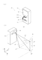
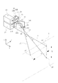
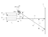
以下、本発明の実施の形態を図面に基づき詳細に説明する。ここに図1は、本発明の一実施形態に係る画像用基準光点照射装置の外観を示し、(a)は正面側の斜視図、(b)は背面側の斜視図であり、図2は図1の画像用基準光点照射装置の内部構造を説明する概略斜視図である。   Hereinafter, embodiments of the present invention will be described in detail with reference to the drawings. FIG. 1 shows the appearance of an image reference light spot irradiating device according to an embodiment of the present invention, wherein (a) is a front perspective view, (b) is a rear perspective view, and FIG. FIG. 2 is a schematic perspective view for explaining the internal structure of the image reference light spot irradiation device of FIG. 1.

図1には、縦型ハンディタイプの画像用基準光点照射装置10が示され、このものは、図2に示すように、独立した第1,第2,第3のレーザ光r1,r2,r3を構造物の壁面や柱などの被写体T上に同時に照射し、当該被写体T上に第1,第2,第3の基準光点p1,p2,p3を生成するとともにこれら基準光点p1〜p3までの距離を測定するものであり、第1〜第3の基準光点p1〜p3は、図1(b)に示すように、第1のレーザ光r1の光軸に直交する仮想投射面(yz平面であり、以下「正対面」ともいう。)N上で三角形の頂点をなす位置関係にある。特に本例では、第1〜第3の基準光点p1〜p3は、当該仮想照射面N上で第1の基準光点p1および第2の基準光点p2を通る第1の直線s1と第1の基準光点p1および第3の基準光点p3を通る第2の直線s2とが互いに直角をなす直角三角形の頂点をなす位置関係にある。   FIG. 1 shows a vertical handy-type image reference light spot irradiation device 10, which includes independent first, second and third laser beams r 1, r 2, as shown in FIG. r3 is simultaneously irradiated onto a subject T such as a wall surface or a pillar of a structure to generate first, second, and third reference light spots p1, p2, p3 on the subject T, and these reference light spots p1 to p1. The distance to p3 is measured, and the first to third reference light spots p1 to p3 are virtual projection planes orthogonal to the optical axis of the first laser beam r1, as shown in FIG. (It is a yz plane, and is also referred to as a “face-to-face” hereinafter.) It is in a positional relationship that forms a vertex of a triangle on N. Particularly in this example, the first to third reference light points p1 to p3 are the first straight line s1 passing through the first reference light point p1 and the second reference light point p2 on the virtual irradiation surface N and the first reference light point p2. The first reference light point p1 and the second straight line s2 passing through the third reference light point p3 are in a positional relationship forming a vertex of a right triangle that is perpendicular to each other.

偏平直方体をなす筐体11の正面には、画像表示部12と、電源ボタン13と、撮影ボタン14と、第1,第2の指示入力部15A,15Bと、が設けられており、筐体11の背面には、第1〜第3のレーザ光r1〜r3を透過させるとともに筐体11内部の構成機器を埃や水分等から保護する例えばガラス製の保護窓16と、後述する撮影部17の撮影レンズ17aとが設けられている。   An image display unit 12, a power button 13, a photographing button 14, and first and second instruction input units 15A and 15B are provided on the front surface of the casing 11 forming a flat rectangular parallelepiped. 11, a protective window 16 made of, for example, glass, which transmits the first to third laser beams r1 to r3 and protects the components inside the casing 11 from dust, moisture, and the like, and an imaging unit 17 to be described later. The photographing lens 17a is provided.

画像表示部12は、例えば液晶ディスプレイであり、後述の演算制御部18から入力された制御信号に基づき撮影画像や各種情報を表示する。画像表示部12は、液晶ディスプレイに限らず、例えば有機ELディスプレイであってもよい。この他、画像表示部12は、ユーザの画面操作に応じた入力信号を演算制御部18へ出力するタッチパネル入力機能を有するものであってもよい。   The image display unit 12 is, for example, a liquid crystal display, and displays a captured image and various types of information based on a control signal input from the calculation control unit 18 described later. The image display unit 12 is not limited to a liquid crystal display, and may be an organic EL display, for example. In addition, the image display unit 12 may have a touch panel input function for outputting an input signal corresponding to a user's screen operation to the calculation control unit 18.

第1,第2の指示入力部15A,15Bは、例えば可変抵抗器を有する操作つまみや操作レバーであり、被写体T上に生成された第2,第3の基準光点p2,p3の移動に関する指示をユーザから受け付け、ユーザの回転操作(回転方向、回転量)に応じた入力信号を演算制御部18へ出力する。   The first and second instruction input units 15A and 15B are, for example, an operation knob or an operation lever having a variable resistor, and are related to the movement of the second and third reference light spots p2 and p3 generated on the subject T. An instruction is received from the user, and an input signal corresponding to the user's rotation operation (rotation direction, rotation amount) is output to the arithmetic control unit 18.

また、図2に示すように、画像用基準光点照射装置10は、筐体11の内部に3つの測距部21,22,23を備えている。第1の測距部21は、第1のレーザ光r1を照射して被写体T上に第1の基準光点p1を生成するとともに、当該第1の基準光点p1までの距離を測定する。第2の測距部22は、第1のレーザ光r1と同一平面(xy平面)内で第2のレーザ光r2を照射して被写体T上に第2の基準光点p2を生成するとともに、当該第2の基準光点p2までの距離を測定する。第3の測距部23は、第1のレーザ光r1と同一平面(xz平面)内で第3のレーザ光r3を照射して被写体T上に第3の基準光点p3を生成するとともに、当該第3の基準光点p3までの距離を測定する。   As shown in FIG. 2, the image reference light spot irradiation device 10 includes three distance measuring units 21, 22, and 23 inside the housing 11. The first distance measuring unit 21 irradiates the first laser beam r1 to generate the first reference light point p1 on the subject T, and measures the distance to the first reference light point p1. The second distance measuring unit 22 irradiates the second laser beam r2 in the same plane (xy plane) as the first laser beam r1 to generate the second reference light point p2 on the subject T, and The distance to the second reference light spot p2 is measured. The third distance measuring unit 23 irradiates the third laser beam r3 in the same plane (xz plane) as the first laser beam r1 to generate a third reference light point p3 on the subject T, and The distance to the third reference light spot p3 is measured.

各測距部21,22,23は公知の光電距離センサであり、図示は省略するが、レーザ光r1,r2,r3を出射する光源およびそこから出射されたレーザ光r1,r2,r3を平行光にする投光レンズ等からなる投光器と、被写体T上で反射したレーザ光r1,r2,r3の反射光を集光する受光レンズおよびそれにより集光された反射光を検知する受光素子等からなる受光器とを有している。   Each of the distance measuring units 21, 22, and 23 is a known photoelectric distance sensor, and although not shown, a light source that emits the laser beams r1, r2, and r3 and the laser beams r1, r2, and r3 emitted from the light sources are parallel. From a light projecting lens composed of a light projecting lens and the like, a light receiving lens that collects the reflected light of the laser beams r1, r2, and r3 reflected on the subject T, and a light receiving element that detects the reflected light collected thereby. And a light receiver.

光源としては、図示例では可視光を出射する可視光レーザダイオードを用いているが、赤外光などの不可視光を出射する不可視光レーザダイオードと可視光レーザダイオードとを併用し、不可視光レーザダイオードにより被写体Tまでの距離測定を行うとともに可視光レーザダイオードにより第1〜第3の基準光点p1,p2,p3を被写体T上に生成するようにしてもよい。   As the light source, a visible light laser diode that emits visible light is used in the illustrated example, but an invisible laser diode that emits invisible light such as infrared light and a visible light laser diode are used in combination. Thus, the distance to the subject T may be measured, and the first to third reference light points p1, p2, and p3 may be generated on the subject T by the visible light laser diode.

受光素子は、被写体Tで反射したレーザ光r1,r2,r3の反射光を受光して信号を出力するものであり、例えばフォトダイオードやフォトトランジスタを用いることができる。   The light receiving element receives reflected light of the laser beams r1, r2, and r3 reflected by the subject T and outputs a signal. For example, a photodiode or a phototransistor can be used.

各測距部21,22,23において、被写体Tまでの距離はTOF(Time of Flight)方式により測定することができる。TOF方式とは、光源から出た光が被写体Tで反射し、受光素子に届くまでの光の飛行時間と光の速度から距離を求めるものであり、この方式は、投光波長と受光波長との間の位相差に基づき距離を算出する位相差測距方式と、所定のパルス幅のレーザ光を投光し、投光時をスタートトリガ、受光時をストップトリガとして投光時と受光時の時間差を計測し、その値に基づき距離を算出するパルス伝播方式とに大別されるが、本実施形態ではいずれの方式を用いてもよい。TOF方式に基づく距離測定のための演算は後述の演算制御部18によって行われる。   In each of the distance measuring units 21, 22, and 23, the distance to the subject T can be measured by a TOF (Time of Flight) method. In the TOF method, the distance from the flight time and the speed of light until the light emitted from the light source is reflected by the subject T and reaches the light receiving element is obtained. A phase difference ranging method that calculates distance based on the phase difference between the two, and a laser beam with a predetermined pulse width is projected, the start trigger is set when the light is projected, and the stop trigger is set when the light is received. Although it is roughly classified into a pulse propagation method in which a time difference is measured and a distance is calculated based on the value, any method may be used in the present embodiment. Calculation for distance measurement based on the TOF method is performed by a calculation control unit 18 described later.

また、第2の測距部22の出側には、第1の固定ミラー25Aと第1の回転ミラー26Aが配設されており、第1の固定ミラー25Aは、第2の測距部22から出射された第2のレーザ光r2を第1の回転ミラー26Aに向けて偏向し、第1の回転ミラー26Aは、第1および第2のレーザ光r1,r2の延在平面(xy平面)に対し垂直な第1の回転軸線z1周りに回転自在とされ、第1の固定ミラー25Aで反射された第2のレーザ光r2を第1のレーザ光r1と同一平面(xy平面)内で偏向方向調整可能に偏向して被写体Tまで導く。   A first fixed mirror 25A and a first rotating mirror 26A are disposed on the exit side of the second distance measuring unit 22, and the first fixed mirror 25A is provided with the second distance measuring unit 22. The second laser beam r2 emitted from the first laser beam is deflected toward the first rotating mirror 26A, and the first rotating mirror 26A is an extended plane (xy plane) of the first and second laser beams r1 and r2. The second laser beam r2 that is rotatable around the first rotation axis z1 perpendicular to the first rotation mirror 25A and is reflected by the first fixed mirror 25A is deflected in the same plane (xy plane) as the first laser beam r1. It is deflected so that the direction can be adjusted and guided to the subject T.

同様に、第3の測距部23の出側には、第2の固定ミラー25Bと第2の回転ミラー26Bが配設されており、第2の固定ミラー25Bは、第3の測距部23から出射された第3のレーザ光r3を第2の回転ミラー26Bに向けて偏向し、第2の回転ミラー26Bは、第1および第3のレーザ光r1,r3の延在平面(xz平面)に対し垂直な第2の回転軸線y1周りに回転自在とされ、第2の固定ミラー25Bで反射された第3のレーザ光r3を第1のレーザ光r1と同一平面(xz平面)内で偏向方向調整可能に偏向して被写体Tまで導く。   Similarly, a second fixed mirror 25B and a second rotating mirror 26B are disposed on the exit side of the third distance measuring unit 23, and the second fixed mirror 25B is a third distance measuring unit. The third laser beam r3 emitted from the beam 23 is deflected toward the second rotating mirror 26B, and the second rotating mirror 26B is an extended plane (xz plane) of the first and third laser beams r1 and r3. The third laser beam r3 that is rotatable about the second rotation axis y1 perpendicular to the second rotation axis 25B and reflected by the second fixed mirror 25B is within the same plane (xz plane) as the first laser beam r1. Deflection is performed so that the deflection direction can be adjusted, and the object T is guided.

本実施形態において、第1,第2の回転ミラー26A,26Bの回転駆動は、回転ミラー駆動手段としての第1,第2のモータ28A,28Bによりそれぞれ行われる。これらのモータ28A,28Bは、回転向き(正回転、逆回転)および回転角(回転量)を制御できるものであれば特に限定はなく、ステッピングモータやサーボモータ(回転検出器付きモータ)などを用いることができる。また、本実施形態では各回転ミラー26A,26Bはギヤ29とピニオン30を介してモータ28A,28Bからの回転動力が伝達されるようになっており、ギヤ29およびピニオン30間のギヤ比を大きくすることで回転角制御の精度を高めることができる。   In the present embodiment, the first and second rotating mirrors 26A and 26B are driven to rotate by first and second motors 28A and 28B as rotating mirror driving means, respectively. These motors 28A and 28B are not particularly limited as long as they can control the rotation direction (forward rotation, reverse rotation) and rotation angle (rotation amount), and stepping motors, servo motors (motors with rotation detectors), etc. Can be used. In this embodiment, the rotary mirrors 26A and 26B are adapted to transmit the rotational power from the motors 28A and 28B via the gear 29 and the pinion 30, and the gear ratio between the gear 29 and the pinion 30 is increased. By doing so, the accuracy of the rotation angle control can be improved.

なお、第1の測距部21の出側には、固定ミラーや回転ミラーは配設されておらず、第1の測距部21から照射された第1のレーザ光r1は水平前方(x方向)に真直ぐ進み、被写体Tに直接投射される。   Note that a fixed mirror and a rotating mirror are not provided on the exit side of the first distance measuring unit 21, and the first laser beam r1 emitted from the first distance measuring unit 21 is horizontal front (x Direction) and projected directly onto the subject T.

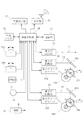
この画像用基準光点照射装置10には、図3の回路構成例に示すように、各種回路に電流を供給する電池等の電源31と、第1,第2のモータ28A,28Bを駆動する第1,第2のモータドライバ32A,32Bと、被写体Tを第1〜第3の基準光点p1〜p3とともに撮影する撮影手段としての撮影部17と、撮影部17で撮影された画像データや各測距部21〜23で測定された測定データ等をスマートフォンやパーソナルコンピュータなどの不図示の外部端末に送信する送信器33と、外部メモリ34と、演算制御部18とが内蔵されている。   As shown in the circuit configuration example of FIG. 3, the image reference light spot irradiating device 10 drives a power source 31 such as a battery for supplying current to various circuits and first and second motors 28A and 28B. The first and second motor drivers 32A and 32B, the photographing unit 17 as photographing means for photographing the subject T together with the first to third reference light spots p1 to p3, the image data photographed by the photographing unit 17, A transmitter 33 that transmits measurement data measured by the distance measuring units 21 to 23 to an external terminal (not shown) such as a smartphone or a personal computer, an external memory 34, and an arithmetic control unit 18 are incorporated.

撮影部17は、CCD(Charge Couple Device)やCMOS(Complementary Metal
Oxide Semiconductor)などの撮像素子、撮影レンズ、不図示の絞りおよびシャッタからなり、撮影ボタン14からの入力操作に応じて静止画や動画の撮像を行い、撮影画像をデジタルデータとして取得してSDカード等の外部メモリ34や不図示の内蔵メモリに記録する。
The photographing unit 17 is a CCD (Charge Couple Device) or CMOS (Complementary Metal).
Oxide Semiconductor) and other imaging elements, an imaging lens, a diaphragm and a shutter (not shown), and in response to an input operation from the shooting button 14, a still image or a moving image is captured, and the captured image is acquired as digital data to obtain an SD card. Or the like in an external memory 34 or a built-in memory (not shown).

演算制御部18は、第1〜第3の測距部21〜23、第1,第2のモータ28A,28B、送信器33、画像表示部12、撮影部17を含む全ての制御を司る機能を有するとともに、第1の測距部21からの距離データと、第2の測距部22からの距離データと、第1および第2のレーザ光r1,r2のなす角(第1のモータ28Aの回転角)αに基づき被写体T上の第1および第2の基準光点p1,p2間の距離Aを演算するとともに、第1の測距部21からの距離データと、第3の測距部23からの距離データと、第1および第3のレーザ光r1,r3のなす角(第2のモータ28Bの回転角)βに基づき被写体T上の第1および第3の基準光点p1,p3間の距離Bを演算する演算手段としての機能を有する。また、筐体11正面に設けられた第1,第2の指示入力部15A,15Bも当該演算制御部18に接続されており、ユーザが指示入力部15A,15Bを操作するとその信号が演算制御部18を経て第1,第2のモータドライバ32A,32Bに伝わり、第1,第2の指示入力部15A,15Bの操作方向および操作量に応じて第1,第2のモータ28A,28Bが駆動されるようになっている。従って、第1,第2の指示入力部15A,15Bと当該演算制御部18と第1,第2のモータドライバ32A,32Bと第1,第2のモータ28A,28Bとは、第1,第2の操作手段を構成する。   The arithmetic control unit 18 is a function that performs all control including the first to third distance measuring units 21 to 23, the first and second motors 28A and 28B, the transmitter 33, the image display unit 12, and the photographing unit 17. And an angle (first motor 28A) formed by the distance data from the first distance measuring unit 21, the distance data from the second distance measuring unit 22, and the first and second laser beams r1 and r2. The distance A between the first and second reference light points p1 and p2 on the subject T is calculated based on α and the distance data from the first distance measurement unit 21 and the third distance measurement. The first and third reference light points p1 and p1 on the subject T based on the distance data from the unit 23 and the angle (rotation angle of the second motor 28B) β formed by the first and third laser beams r1 and r3. It has a function as a calculation means for calculating the distance B between p3. The first and second instruction input units 15A and 15B provided on the front surface of the housing 11 are also connected to the calculation control unit 18, and when the user operates the instruction input units 15A and 15B, the signals are calculated and controlled. The first and second motor drivers 32A and 32B are transmitted to the first and second motor drivers 32A and 32B via the unit 18, and the first and second motors 28A and 28B are operated according to the operation directions and operation amounts of the first and second instruction input units 15A and 15B. It is designed to be driven. Therefore, the first and second instruction input units 15A and 15B, the calculation control unit 18, the first and second motor drivers 32A and 32B, and the first and second motors 28A and 28B are the first and second motors. 2 operation means are configured.

次に、本実施形態の画像用基準光点照射装置10の動作について説明する。   Next, the operation of the image reference light spot irradiation device 10 of the present embodiment will be described.

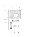
まず、ユーザが電源ボタン13を押すとその信号が演算制御部18に入力され、図1および図2に示すように、第1〜第3の測距部21〜22から第1〜第3のレーザ光r1〜r3が出射され、ユーザが筐体11の背面側を被写体に向けることで、図2に示すように被写体T上に相互に三角形の位置関係をなす第1〜第3の基準光点p1〜p3が生成され、その様子は撮影部17を介して、図4に示すように画像表示部12に映し出される。画像表示部12の画面中の被写体Tから第2,第3のレーザ光r2,r3が外れている場合には、ユーザは指示入力部15A,15Bを適宜操作することで第2,第3のレーザ光r2,r3の向きを変更して被写体T上に第2,第3の基準光点p2,p3を位置させることができる。このようにレーザ光r1〜r3が照射されている間、演算制御部18は、第1および第2の基準光点p1,p2間の距離Aと第1および第3の基準光点p2,p3間の距離Bとを常時演算する。   First, when the user presses the power button 13, the signal is input to the arithmetic control unit 18, and as shown in FIGS. 1 and 2, the first to third ranging units 21 to 22 to the first to third ranging units. Laser beams r1 to r3 are emitted, and the user directs the back side of the casing 11 toward the subject, so that the first to third reference lights that form a triangular positional relationship on the subject T as shown in FIG. Points p1 to p3 are generated, and the state is displayed on the image display unit 12 as shown in FIG. When the second and third laser beams r2 and r3 are off the subject T on the screen of the image display unit 12, the user appropriately operates the instruction input units 15A and 15B to perform the second and third operations. The second and third reference light points p2 and p3 can be positioned on the subject T by changing the directions of the laser beams r2 and r3. While the laser beams r1 to r3 are irradiated in this way, the arithmetic control unit 18 determines the distance A between the first and second reference light points p1 and p2 and the first and third reference light points p2 and p3. The distance B between them is always calculated.

具体的には、図5に示すように、第1および第2の基準光点間の距離Aは、第1および第2の測距部21,22の光源位置c1,c2から被写体Tまでのレーザ光r1,r2の長さをl,lとし、第2の測距部22の光源位置c2から第1の回転ミラー26A上の反射点までのレーザ光r2の長さをl’とし、第1の測距部21の光源位置c1から、第1の回転ミラー26A上の上記反射点から第1の測距部21のレーザ光r1に引いた垂線mまでのレーザ光r1の長さをl’とし、第1のモータ28Aの回転角から得られる2本のレーザ光r1,r2の交差角度をαとし、第1の回転ミラー26Aの上記反射点および第1の測距部21のレーザ光r1間の上記垂線mに沿った距離をA’とすると、被写体T上の基準光点p1,p2間の距離Aは、三角測量の原理に基づき、
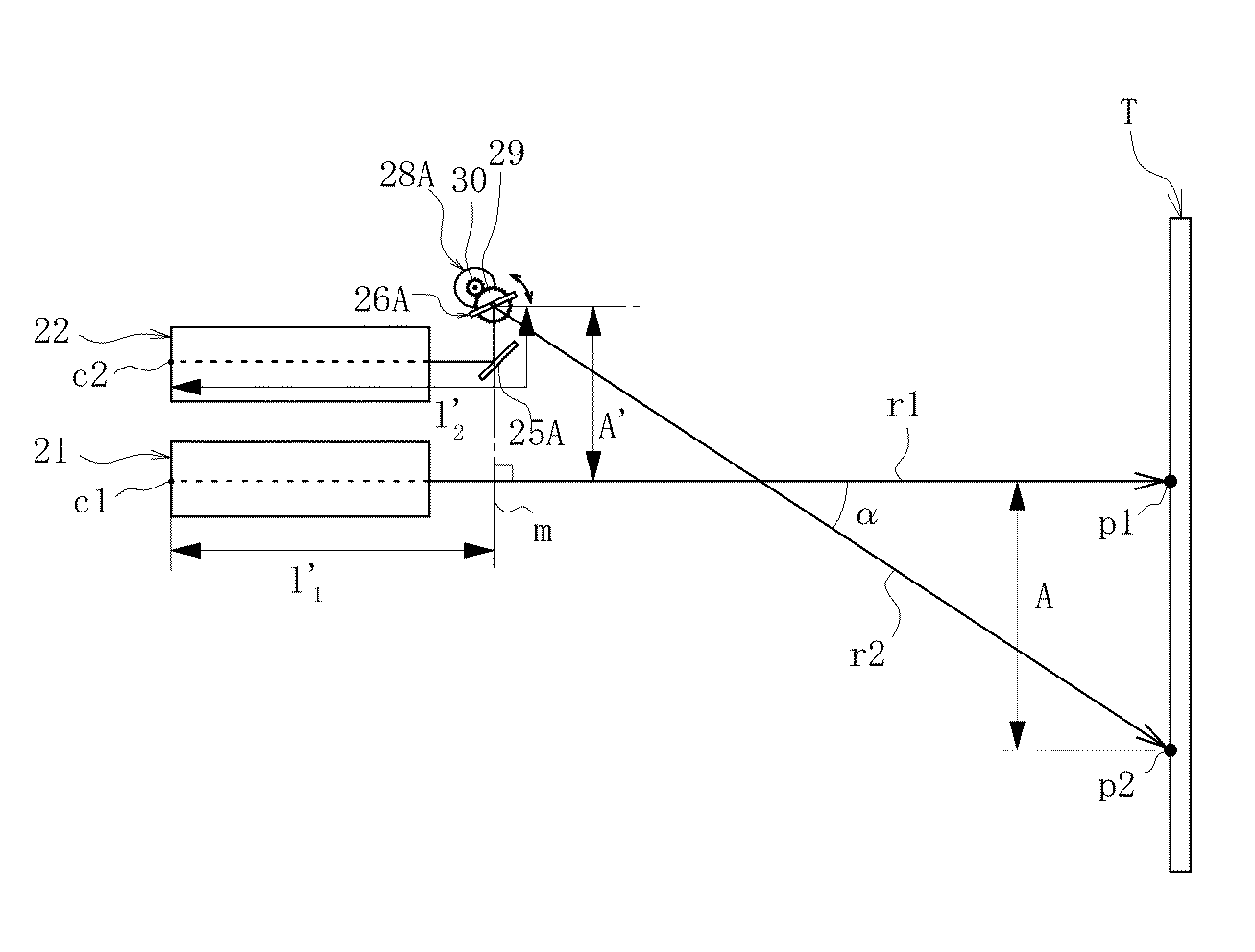
Figure 2017191024
・・・(1)
により求めることができる。 Specifically, as shown in FIG. 5, the distance A between the first and second reference light spots is from the light source positions c1 and c2 of the first and second distance measuring units 21 and 22 to the subject T. The lengths of the laser beams r1 and r2 are l 1 and l 2, and the length of the laser beam r2 from the light source position c2 of the second distance measuring unit 22 to the reflection point on the first rotating mirror 26A is l 2 ′. The length of the laser beam r1 from the light source position c1 of the first ranging unit 21 to the perpendicular m drawn from the reflection point on the first rotating mirror 26A to the laser beam r1 of the first ranging unit 21. It was a l 1 'of the two intersecting angle of the laser beam r1, r2 of the obtained from the rotation angle of the first motor 28A and alpha, the reflection point and the first distance measuring unit of the first rotating mirror 26A When the distance along the perpendicular m between the 21 laser beams r1 is A ′, the reference light points p1 and p2 on the subject T The distance A, based on the principle of triangulation,
Figure 2017191024
... (1)
It can ask for.

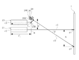
また、第1および第3の基準光点間の距離Bも、距離Aと同様に求めることができ、図6に示すように、第1および第3の測距部21,23の各光源位置c1,c3から被写体Tまでのレーザ光r1,r3の長さをl,lとし、第3の測距部23の光源位置c3から第2の回転ミラー26B上の反射点までのレーザ光r3の長さをl’とし、第1の測距部21の光源位置c1から、第2の回転ミラー26B上の上記反射点から第1の測距部21のレーザ光r1に引いた垂線mまでのレーザ光r1の長さをl’とし、第2のモータ28Bの回転角から得られる2本のレーザ光r1,r3の交差角度をβとし、第2の回転ミラー26Bの上記反射点および第1の測距部21のレーザ光r1間の上記垂線mに沿った距離をB’とすると、被写体T上の基準光点p1,p3間の距離Bは、三角測量の原理に基づき、

Figure 2017191024
・・・(2)
により求めることができる。 Further, the distance B between the first and third reference light spots can be obtained in the same manner as the distance A. As shown in FIG. 6, the light source positions of the first and third distance measuring units 21 and 23 are the same. The lengths of the laser beams r1 and r3 from c1 and c3 to the subject T are set to l 1 and l 3, and the laser beams from the light source position c3 of the third distance measuring unit 23 to the reflection point on the second rotating mirror 26B. The length of r3 is l 3 ′, and the perpendicular drawn from the light source position c1 of the first ranging unit 21 to the laser beam r1 of the first ranging unit 21 from the reflection point on the second rotating mirror 26B. The length of the laser beam r1 up to m is l 1 ′, the crossing angle of the two laser beams r1 and r3 obtained from the rotation angle of the second motor 28B is β, and the reflection of the second rotating mirror 26B is performed as described above. When the distance along the perpendicular m between the point and the laser beam r1 of the first distance measuring unit 21 is B ′, The distance B between the reference point p1, p3 on the body T is based on the principle of triangulation,
Figure 2017191024
... (2)
It can ask for.

これらの距離A,Bを求める演算は、レーザ光r1〜r3が照射されている間常時行われる。なお、第1,第2の回転ミラー26A,26Bの回転中心は第1,第2の回転ミラー26A,26Bの厚み方向中央にあるのに対しレーザ光r2,r3の反射点は第1,第2の回転ミラー26A,26Bの表面上にあり、両者は完全には一致していない等の理由により、第1,第2の回転ミラー26A,26Bの回転角に応じて測定距離に誤差が生じる可能性があるが、この場合、第1,第2の回転ミラー26A,26Bの各回転位置における検出誤差をあらかじめ測定もしくは計算して得られた誤差テーブルを不図示のメモリの格納しておき、演算制御部18において、当該誤差テーブルに基づく誤差補正演算を行うようにしてもよい。   The calculation for obtaining these distances A and B is always performed while the laser beams r1 to r3 are irradiated. Note that the center of rotation of the first and second rotating mirrors 26A and 26B is in the center in the thickness direction of the first and second rotating mirrors 26A and 26B, whereas the reflection points of the laser beams r2 and r3 are the first and first reflecting mirrors. Due to the reason that the two rotating mirrors 26A and 26B are on the surface of the second rotating mirrors 26A and 26B and the two do not completely coincide, an error occurs in the measurement distance depending on the rotation angle of the first and second rotating mirrors 26A and 26B. In this case, in this case, an error table obtained by measuring or calculating a detection error at each rotational position of the first and second rotating mirrors 26A and 26B in advance is stored in a memory (not shown). The calculation control unit 18 may perform an error correction calculation based on the error table.

そして、このように第1〜第3の基準光点p1〜p3が画像表示部12の画面中の被写体T上に存在している状態でユーザが筐体11正面の撮影ボタン14を押すと撮影部17により撮影が行われるとともに、距離A,Bの測定結果はラッチされ、測定データは画像データとともに外部メモリ等に記録される。また、これら画像データおよび測定データは送信器33を介してスマートフォンやパーソナルコンピュータなどの外部端末に送信されるようにしてもよい。   Then, when the user presses the shooting button 14 on the front surface of the housing 11 in a state where the first to third reference light points p1 to p3 are present on the subject T in the screen of the image display unit 12, the shooting is performed. The photographing is performed by the unit 17, the measurement results of the distances A and B are latched, and the measurement data is recorded in an external memory or the like together with the image data. Further, these image data and measurement data may be transmitted to an external terminal such as a smartphone or a personal computer via the transmitter 33.

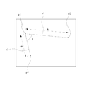
図7に、画像用基準光点照射装置10の撮影部17により被写体Tを3つの基準光点p1〜p3とともに様々な傾斜角度で撮影した様子を示す。図7(a)は、被写体Tが撮影部17の正対面Nに対して鉛直軸線周りにヨー方向に傾いた様子を示し、図7(b)は、被写体Tが撮影部17の正対面Nに対して垂直軸線周りにピッチ方向に傾いた様子を示し、図7(c)は、被写体Tが撮影部17の正対面Nに対してヨー方向およびピッチ方向に傾いた様子を示している。   FIG. 7 shows a state in which the subject T is photographed at various inclination angles together with the three reference light spots p1 to p3 by the photographing unit 17 of the image reference light spot irradiating device 10. 7A shows a state in which the subject T is tilted in the yaw direction around the vertical axis with respect to the face-to-face N of the photographing unit 17, and FIG. 7B is a face-to-face N of the photographing unit 17. 7C shows a state in which the subject T is inclined in the pitch direction around the vertical axis, and FIG. 7C shows a state in which the subject T is inclined in the yaw direction and the pitch direction with respect to the directly-facing surface N of the photographing unit 17.

図7(a)に示すように、被写体Tが撮影部17の正対面Nに対してヨー方向に傾いている場合には、第1および第2の基準光点p1,p2の位置関係、つまり当該基準光点p1,p2までの距離と2点間距離Aとからその傾きを求めることができる。同様に、図7(b)に示すように、被写体Tが撮影部17の正対面Nに対してピッチ方向に傾いている場合には、第1および第3の基準光点p1,p3の位置関係、つまり当該基準光点p1,p3までの距離と2点間距離Bとからその傾きを求めることができる。一方、被写体Tが撮影部17の正対面Nに対してヨー方向およびピッチ方向に同時に傾く場合には、図8に示すように、第1および第2の基準光点p1,p2を結ぶ直線s1と第1および第3の基準光点p1、p3を結ぶ直線s2とのなす角θが変化するため、つまり本例の場合には90°でなくなるため、この角度変化を読み取ることで被写体Tの、正対面Nに対するヨー方向およびピッチ方向の傾きを求めることができる。   As shown in FIG. 7A, when the subject T is tilted in the yaw direction with respect to the facing surface N of the photographing unit 17, the positional relationship between the first and second reference light points p1 and p2, that is, The inclination can be obtained from the distance to the reference light points p1 and p2 and the distance A between the two points. Similarly, as shown in FIG. 7B, when the subject T is inclined in the pitch direction with respect to the directly-facing surface N of the photographing unit 17, the positions of the first and third reference light spots p1 and p3. The inclination can be obtained from the relationship, that is, the distance to the reference light points p1 and p3 and the distance B between the two points. On the other hand, when the subject T is simultaneously tilted in the yaw direction and the pitch direction with respect to the directly facing surface N of the photographing unit 17, as shown in FIG. 8, a straight line s1 connecting the first and second reference light spots p1 and p2. And the straight line s2 connecting the first and third reference light points p1 and p3 change, that is, in this example, it is not 90 °. The inclinations of the yaw direction and the pitch direction with respect to the directly facing surface N can be obtained.

つまり、外部メモリ34等に画像データとともに2点間距離A,Bに関する距離データを関連付けして記憶しておくことで、この画像を画像表示部12または外部端末のディスプレイに呼び出し、第1および第2の基準光点p1,p2を結ぶ直線s1と第1および第3の基準光点p1,p3を結ぶ直線s2のなす角度θを読みとるで、被写体Tの、撮影部17の正対面Nに対する3次元的な傾きを求めることができ、この3次元的な傾きを考慮した上で2点間距離A,Bから画像内に写されているすべての被写体の寸法を解析することができる。   That is, by storing the distance data regarding the distances A and B between the two points together with the image data in the external memory 34 or the like, the image is called on the image display unit 12 or the display of the external terminal, and the first and first By reading the angle θ between the straight line s1 connecting the two reference light points p1 and p2 and the straight line s2 connecting the first and third reference light points p1 and p3, 3 of the subject T with respect to the directly facing surface N of the photographing unit 17 A dimensional inclination can be obtained, and the dimensions of all the objects captured in the image can be analyzed from the distances A and B between the two points in consideration of the three-dimensional inclination.

また、外部メモリ34等に画像データとともに第1〜第3の測距部21〜23から被写体Nまでの各距離および2点間距離A,Bを関連付けして記憶しておくことで、上記2本の直線s1,s2のなす角θの変化を読みとるのに代えて、これらの各種情報に基づいて第1〜第3の基準光点p1〜p3の含まれる面を確定し、面内にあるすべての点の位置関係を演算により求めることもできる。   Further, by storing the distances from the first to third distance measuring units 21 to 23 to the subject N and the distances A and B between the two points together with the image data in the external memory 34 and the like, the above-mentioned 2 Instead of reading the change of the angle θ formed by the straight lines s1 and s2, the plane including the first to third reference light spots p1 to p3 is determined based on these various information and is in the plane. The positional relationship of all points can also be obtained by calculation.

したがって、本実施形態の画像用基準光点照射装置10によれば、撮影する壁等の被写体Tに正確な相対位置関係が既知である3つの基準光点p1〜p3を照射し、被写体Tをこれら基準光点p1〜p3とともに撮影することにより、撮影時に被写体Tが撮影部17の正対面Nに対してヨー方向および/またはピッチ方向に傾いている場合でも当該傾きを考慮した上で撮影された画像中の2点間距離A,Bに基づき画像内の被写体Tの寸法を正確に求めることができる。   Therefore, according to the image reference light spot irradiating device 10 of the present embodiment, the subject T such as a wall to be photographed is irradiated with three reference light spots p1 to p3 whose accurate relative positional relationships are known, and the subject T is irradiated with the subject T. By photographing together with these reference light spots p1 to p3, even when the subject T is tilted in the yaw direction and / or the pitch direction with respect to the directly-facing surface N of the photographing unit 17 at the time of photographing, the photograph is taken in consideration of the inclination. The size of the subject T in the image can be accurately obtained based on the distances A and B between the two points in the image.

また、本実施形態の画像用基準光点照射装置10によれば、撮影部17の正対面N上で、第1および第2の基準光点p1,p2を通る第1の直線s1と第1および第3の基準光点p1,p3を通る第2の直線s2とが互いに直角をなすようにしたので、被写体Tに正対して撮影する場合には、測定したい2点に第1の基準光点p1と第2の基準光点p2または第3の基準光点p3とをそれぞれ合わせるだけで、2点間の横寸法または縦寸法を簡単に測定することができる。   Further, according to the image reference light spot irradiation device 10 of the present embodiment, the first straight line s1 and the first straight line s1 passing through the first and second reference light spots p1 and p2 on the directly-facing surface N of the photographing unit 17. Since the second straight line s2 passing through the third reference light points p1 and p3 is perpendicular to each other, the first reference light is applied to the two points to be measured when photographing the object T directly. The horizontal dimension or the vertical dimension between the two points can be easily measured only by matching the point p1 with the second reference light point p2 or the third reference light point p3.

さらに、本実施形態の画像用基準光点照射装置10によれば、第1,第2の回転ミラー26A,26Bを介して第2,第3のレーザ光r2,r3の偏向方向、ひいては第2,第3の基準光点p2,p3の位置を調整可能な構成としたことにより、画像表示部12の画面中の被写体T上の所期の位置に第2,第3の基準光点p2,p3を容易に移動させることができる。   Further, according to the image reference light spot irradiating device 10 of the present embodiment, the deflection directions of the second and third laser beams r2 and r3 via the first and second rotating mirrors 26A and 26B, and thus the second. , The positions of the third reference light spots p2 and p3 can be adjusted, so that the second and third reference light spots p2 and p2 are placed at desired positions on the subject T in the screen of the image display unit 12. p3 can be easily moved.

さらに、本実施形態の画像用基準光点照射装置10によれば、被写体Tを第1〜3の基準光点p1〜p3とともに撮影する撮影部17を一体に備えるようにしたので、取扱いが容易であるとともに、撮影時の撮影部17の向きと第1〜第3の測距部21〜23の向きを固定して撮影および測距を行うことができるため、高い測定精度を得ることができる。   Furthermore, according to the image reference light spot irradiating device 10 of this embodiment, since the photographing unit 17 for photographing the subject T together with the first to third reference light spots p1 to p3 is integrally provided, handling is easy. In addition, since it is possible to perform shooting and distance measurement while fixing the direction of the photographing unit 17 and the first to third distance measuring units 21 to 23 at the time of photographing, high measurement accuracy can be obtained. .

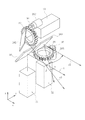
以上、図示例に基づき本発明を説明したが、本発明は前述の実施の形態に限定されるものではなく、特許請求の範囲の記載範囲内において種々の変更を行うことが可能である。例えば、第1〜第3の測距部21〜23は同一方向に配置する必要はなく、図9に示すように、第1および第2の測距部21,22を縦方向に、第3の測距部23を横方向に配置してもよい。より詳細には、第1の測距部21の出側には垂直上向きに出射された第1のレーザ光r1を水平方向前方(x方向)に偏向する固定ミラー35が設けられ、第2の測距部22の出側には、第1の回転ミラー26Aが、垂直上向きに出射されたレーザ光r2を中心として周回可能に設けられている。この第1の回転ミラー26Aは第1のモータ28Aによりリング状のギヤ29とピニオン30を介して回転駆動され、回転ミラー26Aを回転させることで第2の測距部22から照射されたレーザ光r2の偏向方向を水平面(xy平面)内で調整することができる。他方、横向きに配置された第3の測距部23の出側には、第2の回転ミラー26Bが、横向きに出射されたレーザ光r3を中心として周回可能に設けられ、この第2の回転ミラー26Bは、第1の回転ミラー26Aと同様、第2のモータ28Bによりリング状のギヤ29とピニオン30を介して回転駆動され、回転ミラー26Bを回転させることで第3の測距部23から照射されたレーザ光r3の偏向方向を垂直方向(xz平面)内で調整することができる。なお、第1,第2の回転ミラー26A,26Bを回転させると第2,第3の測距部22,23で受光される反射光の、回転ミラー26A,26B上での反射位置は相対的に変化するが、第2,第3の基準光点p2,p3までの距離が同じであれば当該第2,第3の基準光点p2,p3から第2,第3の測距部22,23の各受光素子までの距離は同じであるため、第2,第3の基準光点p2,p3までの距離測定への影響はほぼ無いが、第1,第2の回転ミラー26A,26Bの回転角に応じて誤差が生じる場合には、第1,第2の回転ミラー26A,26Bの各回転位置における検出誤差をあらかじめ測定もしくは計算して得られた誤差テーブルを不図示のメモリの格納しておき、演算制御部18において、当該誤差テーブルに基づく誤差補正演算を行うようにしてもよい。   Although the present invention has been described based on the illustrated examples, the present invention is not limited to the above-described embodiments, and various modifications can be made within the scope of the claims. For example, the first to third distance measuring units 21 to 23 do not have to be arranged in the same direction, and the first and second distance measuring units 21 and 22 are arranged in the vertical direction as shown in FIG. The distance measuring unit 23 may be arranged in the horizontal direction. More specifically, a fixed mirror 35 that deflects the first laser beam r1 emitted vertically upward in the horizontal direction forward (x direction) is provided on the exit side of the first distance measuring unit 21. On the exit side of the distance measuring unit 22, a first rotating mirror 26 </ b> A is provided so as to be able to go around the laser beam r <b> 2 emitted vertically upward. The first rotating mirror 26A is rotationally driven by a first motor 28A via a ring-shaped gear 29 and a pinion 30, and the laser light emitted from the second distance measuring unit 22 by rotating the rotating mirror 26A. The deflection direction of r2 can be adjusted in the horizontal plane (xy plane). On the other hand, a second rotating mirror 26B is provided on the exit side of the third distance measuring unit 23 arranged sideways so as to be able to circulate around the laser beam r3 emitted sideways, and this second rotation. Similarly to the first rotating mirror 26A, the mirror 26B is rotationally driven by the second motor 28B via the ring-shaped gear 29 and the pinion 30, and rotates the rotating mirror 26B from the third distance measuring unit 23. The deflection direction of the irradiated laser beam r3 can be adjusted in the vertical direction (xz plane). When the first and second rotating mirrors 26A and 26B are rotated, the reflected positions of the reflected light received by the second and third distance measuring units 22 and 23 on the rotating mirrors 26A and 26B are relatively relative. However, if the distances to the second and third reference light points p2 and p3 are the same, the second and third distance measuring units 22, 2 from the second and third reference light points p2 and p3, Since the distances to the respective light receiving elements 23 are the same, there is almost no influence on the distance measurement to the second and third reference light points p2 and p3, but the first and second rotating mirrors 26A and 26B When an error occurs according to the rotation angle, an error table obtained by measuring or calculating in advance the detection error at each rotation position of the first and second rotation mirrors 26A and 26B is stored in a memory (not shown). In the arithmetic control unit 18, an error based on the error table is set. It may be performed positive operation.

また、前述の実施形態では、回転ミラー駆動手段としてモータ28A,28Bを設けると説明したが、これに代えて指示入力部15A,15Bからの操作を機械的に回転ミラー26A,26Bに伝達する歯車機構やリンク機構を設けてもよく、この場合回転ミラー26A,26Bの回転角を検出するロータリエンコーダなどの回転角センサを別途に設け、第1,第2のレーザ光r1,r2の交差角度αと第1,第3のレーザ光r1,r3の交差角度βとを求めるようにしてもよい。   In the above-described embodiment, it has been described that the motors 28A and 28B are provided as the rotating mirror driving means. Instead, gears that mechanically transmit the operation from the instruction input units 15A and 15B to the rotating mirrors 26A and 26B. A mechanism or a link mechanism may be provided. In this case, a rotation angle sensor such as a rotary encoder for detecting the rotation angle of the rotary mirrors 26A and 26B is separately provided, and the intersection angle α between the first and second laser beams r1 and r2. And the intersection angle β of the first and third laser beams r1 and r3 may be obtained.

さらに、前述の実施形態では、2つの回転ミラー26A,26Bをモータ28A,28Bにより駆動すると説明したが、回転ミラー26A,26Bは、外周に複数の刻みが形成された円板と該刻み内に脱出可能に嵌り込む球と該球を刻み内に付勢するばねとからなる回転つまみ等を介して、手動による所定角(例えば5°)毎の回転が可能な構成としてもよく、これによれば画像用基準光点照射装置を安価に製作することができる。   Further, in the above-described embodiment, it has been described that the two rotating mirrors 26A and 26B are driven by the motors 28A and 28B. It may be configured such that it can be rotated manually at a predetermined angle (for example, 5 °) via a rotary knob or the like that includes a sphere that is detachably fitted and a spring that biases the sphere into the notch. For example, the image reference light spot irradiation device can be manufactured at low cost.

さらに、前述の実施形態では、レーザ光r1,r2,r3を画像用基準光点照射装置10と被写体Tとの間で交差させる例について説明したが、出射されたレーザ光r1,r2,r3の延長線同士を光源よりも手前側で仮想交点として交差させてもよい。   Furthermore, in the above-described embodiment, the example in which the laser beams r1, r2, and r3 intersect between the image reference light spot irradiating device 10 and the subject T has been described, but the emitted laser beams r1, r2, and r3 The extension lines may intersect as a virtual intersection on the near side of the light source.

さらに、本発明の画像用基準光点照射装置10は、撮影部17を持たず、第1〜第3の測距部21〜23による各種測距結果をカメラ付きのスマートフォン等の外部端末に送信し、当該外部端末のカメラによる撮影時に各種測距結果を画像データとともに関連付けて記録するようにしてもよい。   Furthermore, the image reference light spot irradiating device 10 of the present invention does not have the photographing unit 17 and transmits various distance measurement results by the first to third distance measuring units 21 to 23 to an external terminal such as a smartphone with a camera. Then, various distance measurement results may be recorded in association with the image data at the time of photographing with the camera of the external terminal.

本発明の画像用基準光点照射装置によれば、撮影面がヨー方向および/またはピッチ方向に傾斜している場合においても、撮影した画像からの被写体の寸法読み取りを補助する基準光点を被写体に照射することができる。   According to the image reference light spot irradiating device of the present invention, the reference light spot that assists in reading the dimensions of the subject from the photographed image even when the photographing surface is inclined in the yaw direction and / or the pitch direction. Can be irradiated.

10 画像用基準光点照射装置
11 筐体
12 画像表示部
13 電源ボタン
14 撮影ボタン
15A 第1の指示入力部
15B 第2の指示入力部
17 撮影部
18 演算制御部
21 第1の測距部
22 第2の測距部
23 第3の測距部
25A 第1の固定ミラー
25B 第2の固定ミラー
26A 第1の回転ミラー
26B 第2の回転ミラー
28A 第1のモータ
28B 第2のモータ
31 電源
33 送信器
34 外部メモリ
p1 第1の基準光点
p2 第2の基準光点
p3 第3の基準光点
r1 第1のレーザ光
r2 第2のレーザ光
r3 第3のレーザ光
N 仮想投射面、正対面
T 被写体
DESCRIPTION OF SYMBOLS 10 Reference | standard light spot irradiation apparatus for images 11 Housing | casing 12 Image display part 13 Power button 14 Shooting button 15A 1st instruction | indication input part 15B 2nd instruction | indication input part 17 Imaging | photography part 18 Calculation control part 21 1st ranging part 22 2nd ranging part 23 3rd ranging part 25A 1st fixed mirror 25B 2nd fixed mirror 26A 1st rotating mirror 26B 2nd rotating mirror 28A 1st motor 28B 2nd motor 31 Power supply 33 Transmitter 34 External memory p1 First reference light spot p2 Second reference light spot p3 Third reference light spot r1 First laser light r2 Second laser light r3 Third laser light N Virtual projection plane, positive Face-to-face T Subject

Claims (8)

画像中の被写体の寸法を読み取る際に用いられる基準光点を照射する画像用基準光点照射装置であって、
被写体に第1のレーザ光を照射し、該被写体上に第1の基準光点を生成するとともに該第1の基準光点までの距離を測定する第1の測距部と、
被写体に第2のレーザ光を照射し、該被写体上に第2の基準光点を生成するとともに該第2の基準光点までの距離を測定する第2の測距部と、
被写体に第3のレーザ光を照射し、該被写体上に第3の基準光点を生成するとともに該第3の基準光点までの距離を測定する第3の測距部と、を備え、
前記第1〜第3の基準光点は、前記第1のレーザ光に直交する仮想投射面上で三角形の頂点をなす位置関係にあることを特徴とする画像用基準光点照射装置。
An image reference light spot irradiating device for irradiating a reference light spot used for reading a dimension of a subject in an image,
A first distance measuring unit that irradiates a subject with a first laser beam, generates a first reference light spot on the subject, and measures a distance to the first reference light point;
A second distance measuring unit that irradiates a subject with a second laser beam, generates a second reference light spot on the subject, and measures a distance to the second reference light point;
A third distance measuring unit that irradiates a subject with a third laser beam, generates a third reference light spot on the subject, and measures a distance to the third reference light point;
The image reference light spot irradiating apparatus characterized in that the first to third reference light spots are in a positional relationship forming a vertex of a triangle on a virtual projection plane orthogonal to the first laser light.
前記仮想投射面上で、前記第1および第2の基準光点を通る第1の直線と前記第1および第3の基準光点を通る第2の直線とは互いに直角をなす、請求項1に記載の画像用基準光点照射装置。   2. The first straight line passing through the first and second reference light spots and the second straight line passing through the first and third reference light spots are perpendicular to each other on the virtual projection plane. The reference | standard light spot irradiation apparatus for images as described in any one of. 第1の軸線周りに回転し、前記第2のレーザ光を偏向して前記第2の基準光点を前記第1の直線上で移動させる第1の回転ミラーをさらに備える、請求項2に記載の画像用基準光点照射装置。   3. The apparatus according to claim 2, further comprising a first rotating mirror that rotates around a first axis, deflects the second laser light, and moves the second reference light spot on the first straight line. Reference light spot irradiation device for images. ユーザからの、前記第2の基準光点の移動方向および移動量に関する指示を受け付け、その指示に応じて前記第1の回転ミラーを前記第1の軸線周りに回転させる第1の操作手段をさらに備える、請求項3に記載の画像用基準光点照射装置。   First operating means for receiving an instruction from a user regarding the moving direction and moving amount of the second reference light spot, and rotating the first rotating mirror around the first axis in response to the instruction. The reference light spot irradiation apparatus for images according to claim 3 provided. 第1の軸線周りに回転し、前記第3のレーザ光を偏向して前記第3の基準光点を前記第2の直線上で移動させる第2の回転ミラーをさらに備える、請求項2〜4のいずれか一項に記載の画像用基準光点照射装置。   5. A second rotating mirror that rotates around a first axis, deflects the third laser light, and moves the third reference light spot on the second straight line. 5. The reference | standard light spot irradiation apparatus for images as described in any one of these. ユーザからの、前記第3の基準光点の移動方向および移動量に関する指示を受け付け、その指示に応じて前記第2の回転ミラーを前記第2の軸線周りに回転させる第2の操作手段をさらに備える、請求項5に記載の画像用基準光点照射装置。   A second operation means for receiving an instruction from a user regarding a moving direction and a moving amount of the third reference light spot, and rotating the second rotating mirror around the second axis according to the instruction; The image reference light spot irradiation device according to claim 5, comprising: 被写体を前記第1〜3の基準光点とともに撮影する撮影手段をさらに備える、請求項1〜6のいずれか一項に記載の画像用基準光点照射装置。   The image reference light spot irradiating device according to any one of claims 1 to 6, further comprising photographing means for photographing a subject together with the first to third reference light spots. 前記第1および第2のレーザ光のなす角と前記第1および第2の測距部で測定された第1および第2の基準光点までの距離とから、前記第1および第2の基準光点間の距離を演算するとともに、前記第1および第3のレーザ光のなす角と前記第1および第3の測距部で測定された第1および第3の基準光点までの距離とから、前記第1および第3の基準光点間の距離を演算する演算手段をさらに備える、請求項1〜7のいずれか一項に記載の画像用基準光点照射装置。   From the angles formed by the first and second laser beams and the distances to the first and second reference light points measured by the first and second ranging units, the first and second references While calculating the distance between the light spots, the angle between the first and third laser lights and the distance to the first and third reference light spots measured by the first and third distance measuring sections 8. The image reference light spot irradiation device according to claim 1, further comprising a calculation unit that calculates a distance between the first and third reference light spots.
JP2016080960A 2016-04-14 2016-04-14 Reference light point irradiation device for image Pending JP2017191024A (en)

Priority Applications (1)

Application Number Priority Date Filing Date Title
JP2016080960A JP2017191024A (en) 2016-04-14 2016-04-14 Reference light point irradiation device for image

Applications Claiming Priority (1)

Application Number Priority Date Filing Date Title
JP2016080960A JP2017191024A (en) 2016-04-14 2016-04-14 Reference light point irradiation device for image

Publications (1)

Publication Number Publication Date
JP2017191024A true JP2017191024A (en) 2017-10-19

Family

ID=60084893

Family Applications (1)

Application Number Title Priority Date Filing Date
JP2016080960A Pending JP2017191024A (en) 2016-04-14 2016-04-14 Reference light point irradiation device for image

Country Status (1)

Country Link
JP (1) JP2017191024A (en)

Cited By (4)

* Cited by examiner, † Cited by third party
Publication number Priority date Publication date Assignee Title
JPWO2022176061A1 (en) * 2021-02-17 2022-08-25
JP2023549942A (en) * 2021-10-15 2023-11-29 杭州宇▲樹▼科技有限公司 3D laser radar and legged robot
WO2024200575A1 (en) * 2023-03-28 2024-10-03 Sony Semiconductor Solutions Corporation Object tracking circuitry and object tracking method
KR102807272B1 (en) * 2024-10-08 2025-05-16 주식회사 서랩 Autonomous driving assistance device of agricultural machinery using multiple laser sensors

Citations (8)

* Cited by examiner, † Cited by third party
Publication number Priority date Publication date Assignee Title
JPH07324911A (en) * 1994-05-31 1995-12-12 Keiutsudo:Kk Measuring apparatus of distance
JPH1078305A (en) * 1996-09-04 1998-03-24 Kansai Electric Power Co Inc:The Method and device for measuring concrete crack
JPH10221018A (en) * 1997-02-07 1998-08-21 Puropooto:Kk Three-dimensional measuring method
JP2001165645A (en) * 1999-12-13 2001-06-22 Sharp Corp Portable measuring device
JP2003269955A (en) * 2002-03-11 2003-09-25 Junko Suginaka Measurement device of distance or the like
JP2012063173A (en) * 2010-09-14 2012-03-29 Konica Minolta Opto Inc Laser distance measurement equipment
EP2863175A1 (en) * 2013-10-18 2015-04-22 Techtronic Power Tools Technology Limited Method for measuring an area of a target surface
JP2017187386A (en) * 2016-04-06 2017-10-12 株式会社インザライフ Laser rangefinder

Patent Citations (8)

* Cited by examiner, † Cited by third party
Publication number Priority date Publication date Assignee Title
JPH07324911A (en) * 1994-05-31 1995-12-12 Keiutsudo:Kk Measuring apparatus of distance
JPH1078305A (en) * 1996-09-04 1998-03-24 Kansai Electric Power Co Inc:The Method and device for measuring concrete crack
JPH10221018A (en) * 1997-02-07 1998-08-21 Puropooto:Kk Three-dimensional measuring method
JP2001165645A (en) * 1999-12-13 2001-06-22 Sharp Corp Portable measuring device
JP2003269955A (en) * 2002-03-11 2003-09-25 Junko Suginaka Measurement device of distance or the like
JP2012063173A (en) * 2010-09-14 2012-03-29 Konica Minolta Opto Inc Laser distance measurement equipment
EP2863175A1 (en) * 2013-10-18 2015-04-22 Techtronic Power Tools Technology Limited Method for measuring an area of a target surface
JP2017187386A (en) * 2016-04-06 2017-10-12 株式会社インザライフ Laser rangefinder

Cited By (7)

* Cited by examiner, † Cited by third party
Publication number Priority date Publication date Assignee Title
JPWO2022176061A1 (en) * 2021-02-17 2022-08-25
WO2022176061A1 (en) * 2021-02-17 2022-08-25 三菱電機ビルテクノサービス株式会社 Measurement device and elevator device
JP7276635B2 (en) 2021-02-17 2023-05-18 三菱電機ビルソリューションズ株式会社 Measuring device and elevator device
JP2023549942A (en) * 2021-10-15 2023-11-29 杭州宇▲樹▼科技有限公司 3D laser radar and legged robot
JP7510730B2 (en) 2021-10-15 2024-07-04 杭州宇▲樹▼科技有限公司 3D laser radar and legged robot
WO2024200575A1 (en) * 2023-03-28 2024-10-03 Sony Semiconductor Solutions Corporation Object tracking circuitry and object tracking method
KR102807272B1 (en) * 2024-10-08 2025-05-16 주식회사 서랩 Autonomous driving assistance device of agricultural machinery using multiple laser sensors

Similar Documents

Publication Publication Date Title
EP3457080B1 (en) Surveying instrument
CN105890578B (en) Posture detection device and data acquisition device
CN103492870B (en) Cooperate with the long-range projector with the six degree of freedom laser traces device of mail message
JP6616077B2 (en) Measuring device and 3D camera
CN100430752C (en) position measuring device
CN102159921B (en) Manual type surveying instrument having collimation assisting device
CN100464159C (en) Position detection device
JP6577295B2 (en) measuring device
JP7313955B2 (en) Surveying instrument, surveying method and surveying program
JP6823482B2 (en) 3D position measurement system, 3D position measurement method, and measurement module
US11629959B2 (en) Surveying instrument
JP2005025415A (en) Position detection device
US7490019B2 (en) Method and apparatus for three-dimensional measurement
CN103206926B (en) A kind of panorama three-dimensional laser scanner
JP2022136224A (en) Targets, Survey Methods and Programs
JP2017191024A (en) Reference light point irradiation device for image
JP2014219393A (en) Apparatus for locating machine element
JP2017187386A (en) Laser rangefinder
US10809379B2 (en) Three-dimensional position measuring system, three-dimensional position measuring method, and measuring module
JP7060377B2 (en) Surveying device, surveying control device, surveying control method and surveying control processing program
CN109470201B (en) Method for operating a hand-held laser distance measuring device and hand-held laser distance measuring device
JP2004205222A (en) Distance measuring apparatus
CN116697886A (en) measuring device
US20230280160A1 (en) Surveying instrument
CN111308485A (en) Measuring device and photogrammetry method

Legal Events

Date Code Title Description
A621 Written request for application examination

Free format text: JAPANESE INTERMEDIATE CODE: A621

Effective date: 20190410

A977 Report on retrieval

Free format text: JAPANESE INTERMEDIATE CODE: A971007

Effective date: 20200227

A131 Notification of reasons for refusal

Free format text: JAPANESE INTERMEDIATE CODE: A131

Effective date: 20200407

A02 Decision of refusal

Free format text: JAPANESE INTERMEDIATE CODE: A02

Effective date: 20201020