JP2017190955A - Recognition device - Google Patents
Recognition device Download PDFInfo
- Publication number
- JP2017190955A JP2017190955A JP2016078912A JP2016078912A JP2017190955A JP 2017190955 A JP2017190955 A JP 2017190955A JP 2016078912 A JP2016078912 A JP 2016078912A JP 2016078912 A JP2016078912 A JP 2016078912A JP 2017190955 A JP2017190955 A JP 2017190955A
- Authority
- JP
- Japan
- Prior art keywords
- recognition
- lens barrels
- lifting platform
- attached
- optical axis
- Prior art date
- Legal status (The legal status is an assumption and is not a legal conclusion. Google has not performed a legal analysis and makes no representation as to the accuracy of the status listed.)
- Pending
Links
Images
Abstract
Description
この発明は、例えば、IC(集積回路)、半導体素子等の位置決めマークの認識等に用いられる認識装置に関する。 The present invention relates to a recognition device used for recognition of a positioning mark such as an IC (integrated circuit) or a semiconductor element.
従来、この種の認識装置としては、特開2012−42436号公報(特許文献1)に記載のものがある。 Conventionally, as this kind of recognition device, there is one described in JP 2012-42436 A (Patent Document 1).
この従来の認識装置は、同軸照明部を有する鏡筒からの光を側プリズムで直角に屈曲させ、さらに、2つの平行四辺形プリズムで屈曲して位置決めマーク等の認識対象物に向けて光線を照射するようにしている。 In this conventional recognition device, light from a lens barrel having a coaxial illumination unit is bent at a right angle by a side prism, and further bent by two parallelogram prisms to direct a light beam toward a recognition object such as a positioning mark. I try to irradiate.
しかしながら、上記従来の認識装置では、認識対象物の寸法に応じて平行四辺形プリズムの寸法を変えなければならず、種々の寸法の認識対象物に対応することが困難であると言う問題があった。 However, the conventional recognition device has a problem that it is difficult to deal with recognition objects of various dimensions because the dimensions of the parallelogram prism must be changed according to the dimensions of the recognition object. It was.
最近、小型情報端末はより高精細化し、また、ウエアラブル端末はより小型化、軽量化が進んでいる。このため、ICのサイズも、従来よりも遥かに小さい35mmから2mm程のものが使用されるようになってきており、また、高精度な2μm程度の実装も要求されるようになってきた。 Recently, miniaturized information terminals have become higher definition, and wearable terminals have become smaller and lighter. For this reason, ICs having a size of 35 mm to 2 mm, which is much smaller than conventional ones, have been used, and high-precision mounting of about 2 μm has been required.
これに対して、上記従来の認識装置では、35mmから2mm程の広範囲な寸法に対応することができず、また、ワーキングディスタンス(Working Distance:鏡筒端から認識対象物までの距離)が変動するため、高精細で安定した認識ができないという問題があった。 On the other hand, the conventional recognition apparatus cannot cope with a wide range of dimensions from 35 mm to 2 mm, and the working distance (working distance: distance from the end of the lens barrel to the recognition object) varies. Therefore, there is a problem that high-definition and stable recognition cannot be performed.
そこで、この発明の課題は、広範囲な寸法の対象物の認識を行うことができ、かつ、ワーキングディスタンスを一定にして、高精細で安定した認識を行うことができる認識装置を提供することにある。 SUMMARY OF THE INVENTION An object of the present invention is to provide a recognition apparatus that can recognize an object having a wide range of dimensions, and that can perform high-definition and stable recognition with a constant working distance. .
上記課題を解決するため、この発明の認識装置は、
本体
上記本体に取り付けられると共に、断面が直角2等辺三角形状の一体のセンタープリズムと、
上記本体に沿って昇降できる昇降台と、
上記昇降台に取り付けられると共に、同軸照明部を有する互いに平行な第1および第2鏡筒と、
上記昇降台に取り付けられると共に、上記第1および第2鏡筒の一端側に配置された第1および第2撮像装置と、
上記昇降台に取り付けられると共に、上記第1および第2鏡筒の他端側に配置された第1および第2側反射部材と
を備え、
上記第1および第2鏡筒、第1および第2撮像装置および第1および第2側反射部材は、上記昇降台の昇降に伴って、一体になって昇降し、
上記第1および第2鏡筒の光軸方向の第1および第2光線は、上記第1および第2側反射部材によって上記光軸方向と直角に屈曲させられて、上記センタープリズムの側面に照射されて、それらの側面でさらに直角に屈曲させられて、認識対象物に向けて照射されるように構成されていることを特徴としている。
In order to solve the above problems, the recognition device of the present invention is:
The main body is attached to the main body and has an integral center prism having a cross section of a right isosceles triangle,
A lifting platform that can be moved up and down along the body;
First and second lens barrels attached to the lifting platform and having a coaxial illumination part and parallel to each other;
First and second imaging devices attached to the lift and disposed on one end side of the first and second lens barrels;
The first and second reflecting members are attached to the lifting platform and disposed on the other end side of the first and second lens barrels,
The first and second lens barrels, the first and second imaging devices, and the first and second reflection members are lifted and lowered integrally with the lifting and lowering of the lifting platform,
The first and second light beams in the optical axis direction of the first and second lens barrels are bent at right angles to the optical axis direction by the first and second side reflecting members, and irradiated on the side surfaces of the center prism. Further, it is characterized in that it is bent at a right angle on the side surfaces and irradiated toward the recognition object.
なお、この明細書では、上記第1および第2撮像装置が昇降台に直接取り付けている場合に限らず、上記第1および第2鏡筒を介して間接的に昇降台に取り付けられていても、昇降台に取り付けられていると言う。上記第1および第2側反射部材についても、同様で、直接昇降台に取り付けられている場合に限らず、上記第1および第2側反射部材が第1および第2鏡筒を介して間接的に昇降台に取り付けられていても、この明細書では、上記第1および第2側反射部材が昇降台に取り付けられていると言う。 In this specification, the first and second imaging devices are not limited to being directly attached to the lifting platform, but may be indirectly attached to the lifting platform via the first and second lens barrels. Say it is attached to the platform. The same applies to the first and second side reflecting members, not limited to the case where the first and second side reflecting members are directly attached to the lifting platform, but the first and second side reflecting members are indirectly connected via the first and second lens barrels. In this specification, it is said that the first and second reflecting members are attached to the lifting platform even if they are attached to the lifting platform.
上記構成の認識装置によれば、上記昇降台を昇降させることによって、上記第1および第2鏡筒、第1および第2撮像装置および第1および第2側反射部材が一体になって昇降するため、上記第1および第2側反射部材によって、直角に屈曲された第1および第2光線のセンタープリズムの側面への照射位置が上下し、これによって、第1光線と第2光線との間の距離、つまり、認識対象物の寸法を簡単に広範囲に調整でき、広範囲な寸法の認識対象物を認識することができる。 According to the recognition device having the above-described configuration, the first and second lens barrels, the first and second imaging devices, and the first and second side reflecting members are integrally moved up and down by moving the lifting platform up and down. Therefore, the irradiation position of the first and second light beams bent at right angles to the side surface of the center prism is moved up and down by the first and second side reflecting members, and thereby the space between the first light beam and the second light beam is increased. , That is, the dimension of the recognition object can be easily adjusted over a wide range, and the recognition object having a wide range of dimensions can be recognized.
特に、上記センタープリズムが、断面が直角2等辺三角形状の一体の構造で、内部に仕切り壁等がないため、上記昇降台を上昇させて上記センタープリズムの頂点近くの側面で、上記第1および第2光線を反射させて、第1光線と第2光線との距離を微小距離にして、例えば、2mm程度の微小距離の認識対象物(マーカ等)も認識することができる。 In particular, the center prism has an integral structure with a right-angled isosceles triangle shape and has no partition wall or the like inside, so that the first and the first and By recognizing the second light beam and setting the distance between the first light beam and the second light beam to a minute distance, for example, a recognition object (marker or the like) having a minute distance of about 2 mm can also be recognized.
また、上記第1および第2鏡筒、第1および第2撮像装置および第1および第2側反射部材は、上記昇降台の昇降に伴って、一体になって昇降し、上記第1および第2鏡筒の光軸方向の第1および第2光線は、上記第1および第2側反射部材によって上記光軸方向と直角に屈曲させられて、上記断面が直角2等辺三角形状の一体のセンタープリズムの側面に照射されて、それらの側面でさらに直角に屈曲させられるから、ワーキングディスタンスが変動することがなく、一定であるため、画像がぼやけることがなくて、高精細で安定した認識ができる。 In addition, the first and second lens barrels, the first and second imaging devices, and the first and second reflecting members are lifted and lowered together with the lifting and lowering of the lifting platform. The first and second light beams in the optical axis direction of the two lens barrels are bent at right angles to the optical axis direction by the first and second side reflecting members, and the cross section is an integral center having a right isosceles triangle shape. Irradiated onto the sides of the prism and bent at a right angle on those sides, the working distance does not vary and is constant, so the image is not blurred and high-definition and stable recognition is possible. .
また、上記構成の発明では、上記第1および第2鏡筒、第1および第2撮像装置および第1および第2側反射部材が取り付けられた上記昇降台が、上記断面が直角2等辺三角形状の一体のセンタープリズムが取り付けられた本体に沿って昇降し、本体の後面側に位置し、本体の前面側、側面側が空いているから、レイアウトが容易である。 In the invention having the above-described configuration, the lifting platform to which the first and second lens barrels, the first and second imaging devices, and the first and second reflecting members are attached has an isosceles right triangular shape in cross section. Since the main body is mounted on the rear surface side of the main body, and the front and side surfaces of the main body are vacant, the layout is easy.
1実施形態では、
上記センタープリズムの頂点から延びる遮蔽板を有する。
In one embodiment,
A shielding plate extending from the apex of the center prism;
上記実施形態では、上記遮蔽板で乱光を遮ることができるから、高精細な認識ができる。 In the said embodiment, since a disturbing light can be interrupted | blocked with the said shielding board, high-definition recognition can be performed.
1実施形態では、
上記昇降台を昇降させるように駆動する昇降駆動装置を備える。
In one embodiment,
An elevating drive device that drives the elevating table to move up and down is provided.
上記実施形態では、上記昇降駆動装置を備えるから、昇降台を自動的に精度の高い制御をして、迅速に昇降させることができる。 In the said embodiment, since the said raising / lowering drive device is provided, a raising / lowering stand can be automatically controlled with high precision and can be raised / lowered rapidly.
この発明によれば、広範囲な寸法の対象物の認識を行うことができ、かつ、ワーキングディスタンスを一定にして、高精細で安定した認識を行うことができる。 According to the present invention, it is possible to recognize an object having a wide range of dimensions, and to perform high-definition and stable recognition with a constant working distance.
以下、この発明を図示の実施形態により詳細に説明する。 Hereinafter, the present invention will be described in detail with reference to the illustrated embodiments.
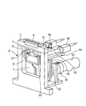
図1に示すように、この実施形態の認識装置は、中央に開口1を有する枠状の本体2を備え、この本体2の開口1に垂下した支持部材3で、断面が直角2等辺三角形状の一体のセンタープリズム5を支持している。このセンタープリズム5は、斜辺を底面側としている。
As shown in FIG. 1, the recognition device of this embodiment includes a frame-like
また、上記本体2の上梁部7には、例えば、石英ガラスや単なる開口からなる光透過部6を設けて、この光透過部7を、センタープリズム5で上方に反射された光線が透過できるようにしている。この光透過部7の上方には、図示しないが、被認識物としてのIC(集積回路)、ACF(異方性導電シート)、ガラス基板、FPC(フレキシブル印刷回路基板)等が配置される。
Further, the upper beam portion 7 of the
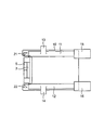
上記本体2の後面側には、図1および2に示すように、本体2に沿って昇降できる昇降台10を設けている。この昇降台10には、第1鏡筒11と第2鏡筒12とを互いに平行に取り付けている。上記第1鏡筒11と第2鏡筒12とには、同軸照明部13,14を設けており、同軸照明ができるようにしている。上記同軸照明部13,14に、公知の構造で、図示しないが、LED、半導体レーザ等の光源部と、ハーフミラーを有する。
On the rear surface side of the
上記第1および第2鏡筒11,12の一端側には、第1および第2撮像装置15,16を取り付けている。上記第1および第2撮像装置15,16は、例えば、CCDカメラ等である。
First and
なお、上記第1および第2撮像装置15,16は上記第1および第2鏡筒11,12に取り付けているが、直接、昇降台10に取り付けてもよい。
Although the first and
一方、上記昇降台10には、上記第1および第2鏡筒11,12の他端側に位置するように、第1および第2側反射部材としての第1および第2側プリズム21,22を取り付けている。上記第1および第2側プリズム21,22は、三角柱状であり、上記第1および第2鏡筒11,12の光軸方向の第1および第2光線は、上記第1および第2側プリズム21,22によって上記光軸方向と直角に屈曲させられて、上記センタープリズム5の側面に照射されて、それらの側面でさらに直角に屈曲させられて、透過部6を通って図示しない認識対象物に向けて照射されるようになっている。
On the other hand, the
また、上記昇降台10は、本体2に設けたガイド部材19で案内して、昇降駆動装置30で昇降させるようにしている。この昇降駆動装置30は、サーボモータやステッピングモータ等のモータ31と、このモータ31の回転力を、昇降台10を昇降させる直線運動の力に変える例えばカム機構や送りネジ機構やボールネジなどからなる伝達機構32とからなる。
The
このように、上記昇降駆動装置30によって、昇降台10を自動的に精度の高い制御をして、迅速に昇降させることができるようにしている。
Thus, the lifting / lowering
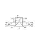
また、図3に示すように、上記センタープリズム5の頂点から延びる遮蔽板40を設けて、上記センタープリズム5の左右の光(乱交)を遮って、IC等の被認識物50の高精細な認識ができるようにしている。
Further, as shown in FIG. 3, a shielding
上記構成の認識装置おいて、上記昇降台10を昇降駆動装置30によって下方に位置させて、図3に示すように、昇降台10上の第1および第2側プリズム21,22等を下方に位置させると、第1および第2鏡筒11,12の光軸方向の第1および第2光線L1,L2は、第1および第2側プリズム21,22によって、直角に屈曲されて、センタープリズム5の側面の下方の位置に照射されて、これによって、第1光線L1と第2光線L2は、広い間隔で被対象物50に照射される。
In the recognition device having the above-described configuration, the
一方、上記昇降台10を昇降駆動装置30によって上方に位置させて、図3に一点鎖線で示すように、昇降台10上の第1および第2側プリズム21,22等を上方に位置させると、第1および第2鏡筒11,12の光軸方向の第1および第2光線L11,L22は、第1および第2側プリズム21,22によって、直角に屈曲されて、センタープリズム5の側面の上方の位置に照射されて、これによって、第1光線L11と第2光線L22は、狭い間隔で被対象物50に照射される。
On the other hand, when the
このように、上記昇降台10を昇降駆動装置30によって適宜昇降させることによって、被対象物50に照射される第1光線L1,Ll1と第2光線L2,L22との間隔を簡単に広範囲に調整でき、広範囲な寸法の認識対象物50を認識することができる。
In this way, the distance between the first light beam L1, L11 and the second light beam L2, L22 applied to the
特に、上記センタープリズム5が、断面が直角2等辺三角形状の一体の構造で、内部に仕切り壁等がないため、上記昇降台10を上昇させて上記センタープリズム5の頂点近くの側面で、上記第1および第2光線L11,L22を反射させて、第1光線L11と第2光線L22との距離を微小距離にして、例えば、2mm程度の微小距離の認識対象物(マーカ等)も認識することができる。
In particular, the
また、上記第1および第2鏡筒11,12、第1および第2撮像装置15,16および第1および第2側プリズム21,22は、上記昇降台10の昇降に伴って、一体になって昇降し、上記第1および第2鏡筒11,12の光軸方向の第1および第2光線は、上記第1および第2側反射部材によって上記光軸方向と直角に屈曲させられて、上記断面が直角2等辺三角形状の一体のセンタープリズム5の側面に照射されて、それらの側面でさらに直角に屈曲させられるから、ワーキングディスタンスが変動することがなく、一定であるため、画像がぼやけることがなくて、高精細で安定した認識ができる。
The first and second lens barrels 11 and 12, the first and
なお、上記第1光線L1,Ll1と第2光線L2,L22とは、平行状態で走行する。 The first light beam L1, L11 and the second light beam L2, L22 travel in a parallel state.
また、上記第1および第2鏡筒11,12、第1および第2撮像装置15,16および第1および第2側プリズム21,22が取り付けられた上記昇降台10が、上記断面が直角2等辺三角形状の一体のセンタープリズム5が取り付けられた本体2に沿って昇降し、本体2の後面側に位置し、本体2の前面側、側面側が空いているから、この認識装置のレイアウトが容易である。
Further, the
上記実施形態では、第1および第2側反射部材として、プリズムを用いたが、鏡を用いてもよい。 In the above embodiment, prisms are used as the first and second reflecting members, but mirrors may be used.
また、上記実施形態では、昇降駆動装置30を備えるが、昇降台10をマイクロメータで送り量を測定できる送りネジ機構などで、手動で昇降させるようにしてもよい。
Moreover, although the raising / lowering
2 本体
5 センタープリズム
10 昇降台
11,12 鏡筒
13,14 同軸照明部
15,16 撮像装置
21,22 側プリズム
30 昇降駆動装置
40 遮蔽板
50 被認識物
2
Claims (3)
上記本体に取り付けられると共に、断面が直角2等辺三角形状の一体のセンタープリズムと、
上記本体に沿って昇降できる昇降台と、
上記昇降台に取り付けられると共に、同軸照明部を有する互いに平行な第1および第2鏡筒と、
上記昇降台に取り付けられると共に、上記第1および第2鏡筒の一端側に配置された第1および第2撮像装置と、
上記昇降台に取り付けられると共に、上記第1および第2鏡筒の他端側に配置された第1および第2側反射部材と
を備え、
上記第1および第2鏡筒、第1および第2撮像装置および第1および第2側反射部材は、上記昇降台の昇降に伴って、一体になって昇降し、
上記第1および第2鏡筒の光軸方向の第1および第2光線は、上記第1および第2側反射部材によって上記光軸方向と直角に屈曲させられて、上記センタープリズムの側面に照射されて、それらの側面でさらに直角に屈曲させられて、認識対象物に向けて照射されるように構成されていることを特徴とする認識装置。 The main body is attached to the main body and has an integral center prism having a cross section of a right isosceles triangle,
A lifting platform that can be moved up and down along the body;
First and second lens barrels attached to the lifting platform and having a coaxial illumination part and parallel to each other;
First and second imaging devices attached to the lift and disposed on one end side of the first and second lens barrels;
The first and second reflecting members are attached to the lifting platform and disposed on the other end side of the first and second lens barrels,
The first and second lens barrels, the first and second imaging devices, and the first and second reflection members are lifted and lowered integrally with the lifting and lowering of the lifting platform,
The first and second light beams in the optical axis direction of the first and second lens barrels are bent at right angles to the optical axis direction by the first and second side reflecting members, and irradiated on the side surfaces of the center prism. Then, the recognition apparatus is configured to be further bent at right angles on the side surfaces and irradiated toward the recognition target object.
上記センタープリズムの頂点から延びる遮蔽板を有することを特徴とする認識装置。 The recognition apparatus according to claim 1,
A recognition apparatus comprising a shielding plate extending from a vertex of the center prism.
上記昇降台を昇降させるように駆動する昇降駆動装置を備えることを特徴とする認識装置。 The recognition apparatus according to claim 1 or 2,
A recognizing device comprising an elevating drive device for driving the elevating platform to move up and down.
Priority Applications (1)
| Application Number | Priority Date | Filing Date | Title |
|---|---|---|---|
| JP2016078912A JP2017190955A (en) | 2016-04-11 | 2016-04-11 | Recognition device |
Applications Claiming Priority (1)
| Application Number | Priority Date | Filing Date | Title |
|---|---|---|---|
| JP2016078912A JP2017190955A (en) | 2016-04-11 | 2016-04-11 | Recognition device |
Publications (1)
| Publication Number | Publication Date |
|---|---|
| JP2017190955A true JP2017190955A (en) | 2017-10-19 |
Family
ID=60084837
Family Applications (1)
| Application Number | Title | Priority Date | Filing Date |
|---|---|---|---|
| JP2016078912A Pending JP2017190955A (en) | 2016-04-11 | 2016-04-11 | Recognition device |
Country Status (1)
| Country | Link |
|---|---|
| JP (1) | JP2017190955A (en) |
Citations (7)
| Publication number | Priority date | Publication date | Assignee | Title |
|---|---|---|---|---|
| JPH0714884A (en) * | 1993-04-30 | 1995-01-17 | Matsushita Electric Ind Co Ltd | Device and method for bonding equipment |
| JPH08128805A (en) * | 1994-11-01 | 1996-05-21 | Agency Of Ind Science & Technol | Method and apparatus for noncontact measurement of relative displacement |
| JPH099111A (en) * | 1995-06-22 | 1997-01-10 | Niles Parts Co Ltd | Multi-direction image pickup camera |
| JP2002036953A (en) * | 2000-07-31 | 2002-02-06 | Auto Network Gijutsu Kenkyusho:Kk | Visual recognition device for vehicle surroundings |
| JP2003254714A (en) * | 2002-02-28 | 2003-09-10 | Uht Corp | Method and detector for detecting position, and method of positioning printed circuit board |
| JP2005019873A (en) * | 2003-06-27 | 2005-01-20 | Casio Comput Co Ltd | Method of bonding driver element |
| JP2011039271A (en) * | 2009-08-11 | 2011-02-24 | Hitachi High-Technologies Corp | Mounting apparatus and mounting method of electronic part and mounting alignment method for electronic part |
-
2016
- 2016-04-11 JP JP2016078912A patent/JP2017190955A/en active Pending
Patent Citations (7)
| Publication number | Priority date | Publication date | Assignee | Title |
|---|---|---|---|---|
| JPH0714884A (en) * | 1993-04-30 | 1995-01-17 | Matsushita Electric Ind Co Ltd | Device and method for bonding equipment |
| JPH08128805A (en) * | 1994-11-01 | 1996-05-21 | Agency Of Ind Science & Technol | Method and apparatus for noncontact measurement of relative displacement |
| JPH099111A (en) * | 1995-06-22 | 1997-01-10 | Niles Parts Co Ltd | Multi-direction image pickup camera |
| JP2002036953A (en) * | 2000-07-31 | 2002-02-06 | Auto Network Gijutsu Kenkyusho:Kk | Visual recognition device for vehicle surroundings |
| JP2003254714A (en) * | 2002-02-28 | 2003-09-10 | Uht Corp | Method and detector for detecting position, and method of positioning printed circuit board |
| JP2005019873A (en) * | 2003-06-27 | 2005-01-20 | Casio Comput Co Ltd | Method of bonding driver element |
| JP2011039271A (en) * | 2009-08-11 | 2011-02-24 | Hitachi High-Technologies Corp | Mounting apparatus and mounting method of electronic part and mounting alignment method for electronic part |
Similar Documents
| Publication | Publication Date | Title |
|---|---|---|
| KR102491721B1 (en) | Apparatus for mounting components on a substrate | |
| US8113813B2 (en) | Optical shaping apparatus and shaping base | |
| EP1605228A2 (en) | Stage apparatus and vision measuring apparatus | |
| US10933578B2 (en) | Pattern forming sheet, pattern manufacturing apparatus, and pattern manufacturing method | |
| KR20090118915A (en) | Lighting device for image capturing in electronic component mounting apparatus | |
| KR20160025441A (en) | Lithography apparatus | |
| CN102385261A (en) | Coaxial focusing device and method of photoetching machine | |
| JP2008015314A (en) | Exposure device | |
| JP5373657B2 (en) | Component mounting apparatus and component mounting method | |
| JP5081967B2 (en) | Screen mask measuring device and printing device | |
| KR20150067077A (en) | Exposure device, exposure method and reflecting mirror having mirror bending mechanism | |
| JP2017190955A (en) | Recognition device | |
| JP2002168800A (en) | Appearance inspection device | |
| JP5721222B2 (en) | Electronic component mounting equipment | |
| KR20080021497A (en) | Apparatus for forming pattern with measurement mechanism | |
| JP2007115820A (en) | Component mounting method and apparatus thereof | |
| KR101833611B1 (en) | Measuring apparatus | |
| TW201935143A (en) | Alignment lighting module, alignment device, lithography machine, and alignment method wherein the alignment illumination module includes a coaxial alignment illumination assembly and a drive assembly | |
| JP7356667B2 (en) | alignment device | |
| TW202202950A (en) | Light source device for exposure, lighting device, exposure device, and exposure method | |
| JPWO2019059315A1 (en) | Lighting equipment for exposure, exposure equipment and exposure method | |
| KR102477736B1 (en) | Proximity exposure device and method for proximity exposure | |
| JP2007171667A (en) | Exposure apparatus | |
| KR102003467B1 (en) | Apparatus for Adjusting Deflection of Substrate | |
| KR20220021769A (en) | Relative active align apparatus |
Legal Events
| Date | Code | Title | Description |
|---|---|---|---|
| A02 | Decision of refusal |
Free format text: JAPANESE INTERMEDIATE CODE: A02 Effective date: 20171003 |