JP2017190897A - Air blowing device - Google Patents
Air blowing device Download PDFInfo
- Publication number
- JP2017190897A JP2017190897A JP2016079865A JP2016079865A JP2017190897A JP 2017190897 A JP2017190897 A JP 2017190897A JP 2016079865 A JP2016079865 A JP 2016079865A JP 2016079865 A JP2016079865 A JP 2016079865A JP 2017190897 A JP2017190897 A JP 2017190897A
- Authority
- JP
- Japan
- Prior art keywords
- fan
- heat source
- air
- opening
- fins
- Prior art date
- Legal status (The legal status is an assumption and is not a legal conclusion. Google has not performed a legal analysis and makes no representation as to the accuracy of the status listed.)
- Granted
Links
Images
Landscapes
- Direct Air Heating By Heater Or Combustion Gas (AREA)
Abstract
【課題】送風を行わずに、暖房することができる送風装置を提供する。【解決手段】熱源と、空気を送出するファンとを備える送風装置において、前記熱源の周囲に配置された複数のフィンと、前記熱源及びファンの駆動を制御する制御回路とを備え、前記ファンは前記フィンの間に空気が通流するように配置されており、前記制御回路は、前記熱源及びファンをオンにする第1駆動処理部と、前記熱源をオフにし、前記ファンをオンにする第2駆動処理部と、前記熱源をオンにし、前記ファンをオフにする第3駆動処理部とを有することを特徴とする送風装置。【選択図】図2[Problem] To provide an air blower that can heat without blowing air. [Solution] The air blower includes a heat source and a fan that blows out air, and includes a plurality of fins arranged around the heat source and a control circuit that controls the operation of the heat source and the fan, the fan is arranged so that air flows between the fins, and the control circuit has a first drive processing unit that turns on the heat source and the fan, a second drive processing unit that turns off the heat source and turns on the fan, and a third drive processing unit that turns on the heat source and turns off the fan. [Selected Figure] Figure 2
Description
本発明は、熱源及びファンを備える送風装置に関する。 The present invention relates to a blower device including a heat source and a fan.
以前より、室内に設置することを目的として、ヒータ及びファンを備える送風装置が提案されている。送風装置は、例えば、上下に延びた筒状の筐体と、該筐体の下部に配置された遠心ファンと、前記筐体の中途部に配置されたヒータとを備える。筐体の下部には吸込口が設けられており、筐体の上部には吹出口が設けられている。送風装置は、遠心ファンによって、吸込口から吸気し、吹出口から空気を吹き出す。送風装置は、ヒータ及びファンをオンにする送風する温風運転と、ヒータをオフにして、ファンをオンにする涼風運転とを実行する(例えば特許文献1参照)。 For some time, air blowers including a heater and a fan have been proposed for the purpose of being installed indoors. The blower device includes, for example, a cylindrical casing that extends vertically, a centrifugal fan that is disposed at a lower portion of the casing, and a heater that is disposed in the middle of the casing. A suction port is provided in the lower part of the casing, and a blower outlet is provided in the upper part of the casing. The blower sucks air from the suction port and blows out air from the blower outlet by the centrifugal fan. The blower performs a warm air operation for blowing air to turn on the heater and the fan, and a cool air operation for turning off the heater and the fan to turn on (see, for example, Patent Document 1).
近年では、送風を行わずに、暖房することも求められている。しかし、前記送風装置は、この要望に応えられていない。 In recent years, it is also required to heat without blowing. However, the blower does not meet this demand.
本発明は斯かる事情に鑑みてなされたものであり、送風を行わずに、暖房することができる送風装置を提供することを目的とする。 This invention is made | formed in view of such a situation, and it aims at providing the air blower which can be heated without performing ventilation.
本発明に係る送風装置は、熱源と、空気を送出するファンとを備える送風装置において、前記熱源の周囲に配置された複数のフィンと、前記熱源及びファンの駆動を制御する制御回路とを備え、前記ファンは前記フィンの間に空気が通流するように配置されており、前記制御回路は、前記熱源及びファンをオンにする第1駆動処理部と、前記熱源をオフにし、前記ファンをオンにする第2駆動処理部と、前記熱源をオンにし、前記ファンをオフにする第3駆動処理部とを有することを特徴とする。 A blower device according to the present invention includes a plurality of fins arranged around the heat source and a control circuit that controls driving of the heat source and the fan in a blower device including a heat source and a fan that sends out air. The fan is arranged so that air flows between the fins, and the control circuit turns on the heat source and the fan, turns off the heat source, and turns on the fan. A second drive processing unit that turns on and a third drive processing unit that turns on the heat source and turns off the fan.
本発明においては、熱源の周囲に複数のフィンを配置する。フィンの周囲に筐体は無く、フィンは露出している。ファン及び熱源がオンになった場合、フィンの間を空気が通流して、熱源の熱を、フィンを介して吸収し、送風装置の外部に温風が吹き出る。ファンがオンになり、熱源がオフになった場合、フィンの間を空気が通流して、送風装置の外部に送風される。一方、ファンがオフになり、熱源がオンになった場合、フィンの間で温められた空気はフィンの隙間から外部に出る。送風装置が室内に設置されている場合、自然対流によって、室内は暖められる。 In the present invention, a plurality of fins are arranged around the heat source. There is no housing around the fin, and the fin is exposed. When the fan and the heat source are turned on, air flows between the fins, absorbs the heat of the heat source through the fins, and hot air blows out of the blower. When the fan is turned on and the heat source is turned off, air flows between the fins and is blown outside the blower. On the other hand, when the fan is turned off and the heat source is turned on, the air heated between the fins exits through the gaps between the fins. When the blower is installed in the room, the room is warmed by natural convection.
本発明に係る送風装置は、前記ファンは、前記熱源の一側に配置され、前記熱源側から吸気し、前記熱源の反対側に排気する第1ファンと、前記熱源の他側に配置され、前記熱源の反対側から吸気し、前記熱源側に排気する第2ファンとを有し、前記第1駆動処理部は、前記第1ファンをオンにして、前記第2ファンをオフにし、前記第2駆動処理部は、前記第1ファンをオフにして、前記第2ファンをオンにし、前記第3駆動処理部は、前記第1ファン及び第2ファンをオフにすることを特徴とする。 In the blower according to the present invention, the fan is disposed on one side of the heat source, and is disposed on the other side of the heat source, a first fan that sucks air from the heat source side and exhausts air to the opposite side of the heat source, A second fan that sucks air from the opposite side of the heat source and exhausts air to the heat source side, wherein the first drive processing unit turns on the first fan, turns off the second fan, and The second drive processing unit turns off the first fan and turns on the second fan, and the third drive processing unit turns off the first fan and the second fan.
本発明においては、温風を吹き出す場合、送風装置は第1ファンをオンにして熱源側から吸気し、空気をフィンの間に通して加熱させてから、外部に吹き出す。例えば、第1ファンをフィンの下側に配置することによって、フィンの間を空気は上から下に流れて、外部に出る。外部に出た空気は温められているので上昇し、その後、第1ファンに再度吸い込まれて、空気の循環が円滑に行われる。熱源による加熱を行うこと無く、送風を行う場合、第2ファンをオンにして熱源の反対側から吸気し、空気をフィンに通してから外部に吹き出す。例えば第2ファンをフィンの上側に配置することによって、上側の空気よりも低温である下側の空気が吸い込まれ、上方へ吹き出る。夏場において、相対的に低温の空気を室内に拡散させる。また空気調和機と併用した場合、空気調和機によって冷却された空気を下側から上側に送出し、室内の上側を効果的に冷やして、室内全体を平均的に冷却させることができる。そのため、冬場のみならず、夏場においても、送風装置を効果的に使用することができる。 In the present invention, when blowing warm air, the blower turns on the first fan, sucks air from the heat source side, heats the air through the fins, and blows it outside. For example, by arranging the first fan below the fins, the air flows between the fins from the top to the bottom and exits to the outside. Since the air that has come to the outside is warmed, it rises and is then sucked into the first fan again, so that the air is smoothly circulated. When air is blown without heating by the heat source, the second fan is turned on, air is sucked in from the opposite side of the heat source, air is passed through the fins, and then blown out. For example, by disposing the second fan on the upper side of the fin, the lower air, which is lower in temperature than the upper air, is sucked and blown upward. In summer, relatively cool air is diffused indoors. Further, when used together with an air conditioner, the air cooled by the air conditioner can be sent from the lower side to the upper side, the upper side of the room can be effectively cooled, and the entire room can be cooled on average. Therefore, the blower can be used effectively not only in winter but also in summer.
本発明に係る送風装置は、前記複数のフィンは、前記熱源の周囲に放射状に配置され、先端部がT状に形成された複数のT状フィンを含み、隣合う前記先端部は周方向に離間していることを特徴とする。 In the blower according to the present invention, the plurality of fins include a plurality of T-shaped fins arranged radially around the heat source and having tip portions formed in a T shape, and the adjacent tip portions are circumferentially arranged. It is separated.
本発明においては、複数のT状フィンを熱源の周囲に放射状に配置する。複数のT状フィンは全体として筒状を形成し、温風を吹き出す場合には、この筒状の内側の空間が通気路として機能する。一方、熱源をオンにし、ファンをオフにして自然対流による暖房を行う場合、隣合うT状フィンの先端部の隙間が開口として機能し、温められた空気が前記隙間から外部に出る。すなわち、T状フィンを設けることによって、フィンは通気路及び開口としての二つの機能を併せ持つことができる。 In the present invention, a plurality of T-shaped fins are arranged radially around the heat source. The plurality of T-shaped fins form a tubular shape as a whole, and when blowing warm air, the space inside the tubular shape functions as an air passage. On the other hand, when heating is performed by natural convection with the heat source turned on and the fan turned off, the gap between the tips of adjacent T-shaped fins functions as an opening, and warmed air exits through the gap. That is, by providing a T-shaped fin, the fin can have two functions as an air passage and an opening.
本発明に係る送風装置は、前記第2ファンは吸気口を有し、前記吸気口を開閉する開閉板と、該開閉板を前記吸気口に対して接近させるか又は離間させる接離機構とを備えることを特徴とする。 In the blower according to the present invention, the second fan has an intake port, and includes an open / close plate that opens and closes the intake port, and a contact / separation mechanism that causes the open / close plate to approach or separate from the intake port. It is characterized by providing.
本発明においては、熱源をオンにする場合、接離機構を駆動させて、暖房時に使用しない第2ファンの吸気口を開閉板で塞ぐ。開閉板で吸気口を塞ぐことによって、第2ファンへの温風の移動又は熱の伝導を抑制し、第2ファンの耐用年数を長くすることができる。 In the present invention, when the heat source is turned on, the contact / separation mechanism is driven to close the intake port of the second fan not used during heating with the opening / closing plate. By closing the intake port with the opening / closing plate, the movement of hot air to the second fan or the conduction of heat can be suppressed, and the service life of the second fan can be extended.
本発明に係る送風装置は、前記開閉板による前記吸気口の開閉を検知するセンサを備え、前記制御回路は、前記センサによって閉を検知した場合に、前記熱源をオンにすることを特徴とする。 The blower according to the present invention includes a sensor that detects opening and closing of the intake port by the opening and closing plate, and the control circuit turns on the heat source when closing is detected by the sensor. .
本発明においては、第2ファンの吸気口が閉じられた場合にのみ、熱源をオンにすることによって、第2ファンが不要に熱くなることを防止し、第2ファンの耐用年数を長くすると共に、安全性を高めることができる。 In the present invention, the heat source is turned on only when the intake port of the second fan is closed, thereby preventing the second fan from becoming unnecessarily hot and extending the service life of the second fan. , Can increase safety.
本発明に係る送風装置は、前記接離機構は、前記開閉板の周囲に配置され、周方向に移動する環状スライダと、該環状スライダ及び開閉板を連結する連結部と、前記環状スライダから前記開閉板に向けて突出したカムと、前記開閉板に設けられたカムフォロアとを備えることを特徴とする。 In the blower according to the present invention, the contact / separation mechanism is disposed around the opening / closing plate, and moves in a circumferential direction, a connecting portion that connects the annular slider and the opening / closing plate, and the annular slider from the annular slider. A cam projecting toward the opening / closing plate and a cam follower provided on the opening / closing plate are provided.
本発明においては、環状スライダ及び開閉板に、カム及びカムフォロアを設けることによって、開閉板による第2ファンの吸気口の開閉を実現する。 In the present invention, by providing the annular slider and the opening / closing plate with a cam and a cam follower, the opening / closing of the intake port of the second fan by the opening / closing plate is realized.
本発明に係る送風装置にあっては、熱源の周囲に複数のフィンを配置する。フィンの周囲に筐体は無く、フィンは露出している。ファン及び熱源がオンになった場合、フィンの間を空気が通流して、熱源の熱を、フィンを介して吸収し、送風装置の外部に温風が吹き出る。ファンがオンになり、熱源がオフになった場合、フィンの間を空気が通流して、送風装置の外部に送風される。一方、ファンがオフになり、熱源がオンになった場合、フィンの間で温められた空気はフィンの隙間から外部に出る。送風装置が室内に設置されている場合、自然対流によって、室内は暖められる。そのため、ユーザは、暖房を行う場合に、温風による暖房又は自然対流による暖房のいずれかを、選択することができ、また加熱を伴わない送風を行うこともできる。 In the air blower according to the present invention, a plurality of fins are arranged around the heat source. There is no housing around the fin, and the fin is exposed. When the fan and the heat source are turned on, air flows between the fins, absorbs the heat of the heat source through the fins, and hot air blows out of the blower. When the fan is turned on and the heat source is turned off, air flows between the fins and is blown outside the blower. On the other hand, when the fan is turned off and the heat source is turned on, the air heated between the fins exits through the gaps between the fins. When the blower is installed in the room, the room is warmed by natural convection. Therefore, when performing heating, the user can select either heating by hot air or heating by natural convection, and can perform air blowing without heating.
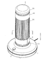
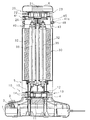
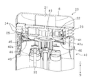
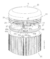
以下本発明を実施の形態に係る送風装置を示す図面に基づいて、説明する。図1は、送風装置の外観斜視図、図2は、送風装置の縦断面図である。送風装置は、平面視円形状をなす偏平な筐体1を備える。以下の説明では、図に記載した上下を使用する。 Hereinafter, the present invention will be described based on the drawings showing a blower according to an embodiment. FIG. 1 is an external perspective view of the blower, and FIG. 2 is a longitudinal sectional view of the blower. The blower device includes a flat housing 1 having a circular shape in plan view. In the following description, the top and bottom described in the figure are used.
筐体1の上面周縁部に回転式の操作スイッチ2が設けられている。操作スイッチ2は、後述する第1運転、第2運転、第3運転及び運転停止のいずれかを選択することができる。筐体1内には制御回路3が設けられており、制御回路3は、操作スイッチ2によって、第1運転、第2運転、第3運転及び停止のいずれを選択したのかを検知する。
A
筐体1の上面中央部に開口4が設けられており、該開口4には、遠心式の第1ファン10が取り付けられている。第1ファン10は、モータ11と、該モータ11の回転軸に連結した羽根12とを備える。モータ11は、その回転軸を上側に向けて開口4の内側に配置されている。羽根12は、開口4の上側に配置されている。羽根12の上側に吸気口15が形成されており、羽根12の周囲に吹出口13が形成されている。吹出口13には、上下方向を軸方向とした円環状をなす二つの整流板14、14が、モータ11の回転軸に対して同軸的に設けられている。二つの整流板14、14は上下方向に並んでいる。
An opening 4 is provided in the center of the upper surface of the housing 1, and a centrifugal
モータ11が回転した場合、上側の空気が吸気口15を介して吸入され、整流板14の径方向において、吹出口13から外向きに吹き出される。
When the
第1ファン10の上側に、筒状の下支持部5が設けられている。下支持部5から上方に離間した位置に、筒状の上支持部40が設けられており、該上支持部40及び下支持部5の間に、熱を伝導するフィンユニット30が設けられている。下支持部5はフィンユニット30を支持する。
A cylindrical
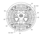
図3は、フィンユニット30を略示するIII―III線を切断線とした部分拡大平面図である。フィンユニット30は、上下に長い柱状の中央支持部31と、上下に長い板状の複数のフィン32とを備える。中央支持部31には、上下に貫通した二つの貫通孔34、34が設けられている。二つの貫通孔34、34には、熱源である上下に長い二つのシーズヒータ35、35がそれぞれ挿入されている。なお単数又は三つ以上のシーズヒータ35をフィンユニット30に設けてもよい。なおシーズヒータ35は熱源の一例であり、他のヒータ、例えばグラファイトヒータ、カートリッジヒータ等を熱源として使用してもよい。
FIG. 3 is a partially enlarged plan view with the III-III line schematically showing the
上下方向に直交する方向(以下横方向又は径方向とも称する)において、複数のフィン32は中央支持部31から放射状に突出している。複数のフィン32は、横方向への突出幅が短いフィン32と、横方向への突出幅が長いフィン32とを備え、前記突出幅が短いフィン32と、前記突出幅が長いフィン32とが、中央支持部31の周方向に沿って交互に配置されている。
In the direction orthogonal to the vertical direction (hereinafter also referred to as the horizontal direction or radial direction), the plurality of
前記突出幅が長いフィン32の突出端部は平面視T状に形成されている(以下、前記突出幅が長いフィン32をT状フィン33とも称する)。複数のT状フィン33は、中央支持部31の周方向に沿って並設されており、隣合うT状フィン33の間には、上下に長いスリットが形成される。そのため、複数のT状フィン33全体によって、上下に長い複数のスリットを周方向に並設した筒形状が形成される。
The protruding end portion of the
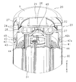
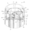
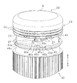
図4は、送風装置の上部構成を上方から視認した縦断面部分斜視図、図5は、底板25の吸気口26が塞がれていない場合における送風装置の上部構成を下方から視認した縦断面部分斜視図である。
4 is a partial perspective view of the vertical section of the upper structure of the blower device as viewed from above, and FIG. 5 is a vertical section of the upper structure of the blower device as viewed from below when the
フィンユニット30の上端には上支持部40が設けられている。上支持部40は、筒状のカバー41と、該カバー41の内側にて、カバー41に対して同軸的に配置された支持筒43を備える。図2に示すように、カバー41の周面部には、周方向に沿ったスロット41aが設けられている。図4に示すように、カバー41の内周面には、後述する環状スライダ45を支持する為の支持環42が設けられている。支持環42は、カバー41と支持筒43との間に位置する。支持環42は、カバー41の内周面から径方向内側に突出した底板部42aと、該底板部42aの突出端から上方に突出した壁部42bとを備える。
An
図4に示すように、支持筒43とカバー41との間には、支持筒43及びカバー41に対して同軸的に、周方向に移動可能な環状スライダ45が設けられている。環状スライダ45は、支持環42によって移動可能に支持されており、前記底板部42a、壁部42b及びカバー41によって形成された空間内に位置する。環状スライダ45からは、径方向外向きにハンドル48が突出しており、ハンドル48はカバー41のスロット41aから外側に突出している(図1参照)。ハンドル48を周方向に移動させることによって、環状スライダ45も周方向に移動する。
As shown in FIG. 4, an
上支持部40の上側には、遠心式の第2ファン20が設けられている。第2ファン20は、モータ21と、該モータ21の回転軸に連結した羽根22と、該羽根22と前記支持筒43及びカバー41との間に配置された平面視円形状の底板25を備える。
On the upper side of the
モータ21は、その回転軸を下側に向けて配置されている。モータ21の上側は、偏平な有底円筒状をなす天井カバー6によって覆われている。天井カバー6は、底部を上側にしてモータ21を覆っている。
The
羽根22は、モータ21の回転軸に連結されている。底板25は羽根22の下側に配置され、その中央部には円形の吸気口26が設けられている。吸気口26の縁部分は上方に湾曲して突出している。羽根22の周囲には、底板25と天井カバー6の縁部分との間において、吹出口23が形成されている。吹出口23には、上下方向を軸方向とした円環状をなす二つの整流板24、24が、モータ21の回転軸に対して同軸的に設けられている。二つの整流板24、24は上下方向に並んでいる。
The
モータ21が回転した場合、下側の空気が吸気口26を介して吸入され、整流板24の径方向において、吹出口23から外向きに吹き出される。
When the
底板25は、支持筒43及びカバー41の上側に配置されている。底板25の吸気口26よりも径方向外側において、底板25とフィンユニット30の中央支持部31との間に、上下に延びた複数の支持板44が設けられている。支持板44は、中央支持部31及び底板25を連結する。また底板25と支持筒43とは連結されている。底板25の周縁部には、上下に貫通した複数の通気孔27が周方向に並設されている。通気孔27は、支持筒43の径方向において、支持板44よりも外側且つ支持筒43の周面よりも内側に配置されている。
The
吸気口26とフィンユニット30の上端との間に、平面視円形状をなし、熱を遮断する為の遮熱板49が設けられている。遮熱板49の中央部分は上方に隆起した円錐台状をなし、底板25の吸気口26に対応した形状をなす。なお図5において、遮熱板49は底板25の吸気口26を塞いでいない。
Between the
図5に示すように、支持筒43の周面には、径方向に貫通した複数の貫通孔43aが周方向に並設されている。遮熱板49の縁部分と前記環状スライダ45とは、細長い板状の連結部46によって連結されている。連結部46は、前記貫通孔43aを通って、遮熱板49及び環状スライダ45を連結している。
As shown in FIG. 5, a plurality of through holes 43 a penetrating in the radial direction are juxtaposed in the circumferential direction on the peripheral surface of the
図6は、底板25の吸気口26が塞がれていない場合におけるカム45a及びカムフォロア46aを略示する部分拡大斜視図である。なお図6において、カバー41及び支持環42の記載を省略している。環状スライダ45には、上方に突出したカム45aが設けられている。カム45aの突出端部には傾斜面45bが形成されている。傾斜面45bの上端部の隣において、カム45aに溝45cが形成されている。傾斜面45bの下端部の隣において、環状スライダ45に凹部45dが形成されている。
FIG. 6 is a partially enlarged perspective view schematically showing the cam 45a and the cam follower 46a when the
連結部46の環状スライダ45側の端部には、環状スライダ45の周方向に延びた板部材46dを介して、カムフォロア46aが設けられている。カムフォロア46aは、板部材46dの長手方向中途部から下方に突出した板状をなし、カムフォロア46aの下端部には、カム45aの傾斜面45bに略平行な傾斜面46bが形成されている。傾斜面46bの下端部の隣において、カムフォロア46aに溝46cが形成されている。カムフォロア46aの傾斜面46bと、カム45aの傾斜面45bとは対面している。カム45aの溝45cと、カムフォロア46aの溝46cとは係合可能な形状をなす。板部材46dの長手方向端部の上側には押圧式のセンサ7が設けられている。
A cam follower 46 a is provided at the end of the connecting
図6において、カム45aの傾斜面45b及びカムフォロア46aの傾斜面46bは略全面が接触している。この場合、図5に示すように、遮熱板49は底板25の吸気口26を塞がない位置(非閉塞位置)に配され、図6に示すように、板部材46dはセンサ7を押圧しない。押圧されていない場合、センサ7は、吸気口26が閉塞されていないことを示す信号を制御回路3に出力する。またカムフォロア46aの下端部は凹部45d内に位置し、環状スライダ45に干渉していない。なおハンドル48、支持環42、環状スライダ45、連結部46、カム45a及びカムフォルダによって、接離機構が構成されている。
In FIG. 6, the
図7は、底板25の吸気口26が塞がれている場合における送風装置の上部構成を上方から視認した縦断面部分斜視図、図8は、底板25の吸気口26が塞がれている場合におけるカム45a及びカムフォロア46aを略示する部分拡大斜視図である。
FIG. 7 is a partial cross-sectional perspective view of the upper structure of the blower device viewed from above when the
図5及び図6に示す状態から、カバー41の周方向において、ハンドル48を一方向に移動させた場合、図8に示すように、カム45aは一方向(図8の右方向)に移動し、カム45a及びカムフォロア46aの各傾斜面45b、46bは相対的に摺動し、カムフォロア46aは上方に移動して、カム45a及びカムフォロア46aの溝45c、46cが係合する。
When the
この場合、図7に示すように、カムフォロア46aの上昇に伴って、遮熱板49も上昇し、底板25の吸気口26を塞ぐ。換言すれば遮熱板49は、吸気口26を塞ぐ位置(閉塞位置)に移動する。また板部材46dの前記端部はセンサ7を押圧する。押圧されたセンサ7は、吸気口26が閉塞されたことを示す信号を制御回路3に出力する。
In this case, as shown in FIG. 7, as the cam follower 46 a rises, the
この状態から、ハンドル48を他方向に移動させた場合、図4〜図6に示すように、カム45aは他方向(図6の左方向)に移動し、カム45a及びカムフォロア46aの溝45c、46cの係合が解除され、カム45a及びカムフォロア46aの各傾斜面45b、46bは相対的に摺動し、カムフォロア46aは下方に移動する。このとき、カムフォロア46aの下端部は凹部45d内に位置し、環状スライダ45に干渉しない。
From this state, when the
この場合、図4及び図5に示すように、カムフォロア46aの下降に伴って、遮熱板49も下降し、底板25の吸気口26を開く。換言すれば、遮熱板49は非閉塞位置に移動する。
In this case, as shown in FIGS. 4 and 5, as the cam follower 46 a is lowered, the
操作スイッチ2の操作によって、シーズヒータ35及び第1ファン10をオンにし、第2ファン20をオフにする第1運転(温風運転)、シーズヒータ35及び第1ファン10をオフにし、第2ファン20をオンにする第2運転(送風運転)、シーズヒータ35をオンにし、第1ファン10及び第2ファン20をオフにする第3運転(自然対流運転)、又は運転停止が選択される。
By operating the
制御回路3は、シーズヒータ35をオンにする第1運転又は第3運転が選択されている場合、センサ7から吸気口26が閉塞されたことを示す信号が入力されているか否かを判定する。センサ7から吸気口26が閉塞されたことを示す信号が入力されていない場合、制御回路3は、選択された第1運転又は第3運転を実行しない。センサ7から吸気口26が閉塞されたことを示す信号が入力されている場合、制御回路3は、選択された第1運転又は第3運転を実行する。
When the first operation or the third operation for turning on the sheathed
すなわち、制御回路3は、第1運転又は第3運転が選択されたことを検知し、且つ吸気口26が閉塞されたことを示す信号が入力されている場合に、第1運転又は第3運転を実行し、シーズヒータ35をオンにする。
That is, the
制御回路3が第1運転(温風運転)を実行する場合、底板25の吸気口26は閉塞されているが、前述したように、底板25の周縁部には通気孔27が設けられているので、この通気孔27を通して空気が通流する。第1運転においては、第1ファン10が駆動し、通気孔27等を通して空気がフィン32間の間を下方に移動して加熱され、第1ファン10の吹出口13から、温風が吹き出る。
When the
前述したように、複数のT状フィン33全体によって、筒形状が形成されているので、筒状の内側の空間が通気路として機能し、空気はフィンユニット30内を円滑に下方に移動することができる。
As described above, since the cylindrical shape is formed by the plurality of T-shaped
制御回路3が第3運転(自然対流運転)を実行する場合、シーズヒータ35がオンになり、フィン32の間の空気が加熱され、加熱された空気はT状フィン33の間のスリットから外部に出て、自然対流による暖房が実現される。
When the
第1運転又は第3運転が実行されている場合、第2ファン20の吹出口23は遮熱板49によって閉塞されている。そのため、第2ファン20のモータ21への温風の移動又は第2ファン20のモータ21への熱伝導が遮断される。
When the first operation or the third operation is being performed, the
制御回路3は第2運転(送風運転)が選択されている場合、センサ7から、吸気口26が閉塞されていないことを示す信号が入力されているか否かを判定する。吸気口26が閉塞されていないことを示す信号が入力されていない場合、制御回路3は第2運転を実行しない。吸気口26が閉塞されていないことを示す信号が入力されている場合、制御回路3は第2ファン20を駆動し、送風運転を実行する。第2ファン20の駆動によって、空気はフィン32の間及び吸気口26を上方に移動し、第2ファン20に吸い込まれ、吹出口23から吹き出される。
When the second operation (air blowing operation) is selected, the
なお遮熱板49が閉塞位置に配されている場合でも、遮熱板49と底板25との間に吸気可能な隙間を確保するように、送風装置を構成してもよい。この場合、第2運転が選択されていれば、制御回路3は、吸気口26が閉塞されていないことを示す信号が入力されていなくても、第2運転を実行してもよい。
Even when the
実施の形態にあっては、シーズヒータ35の周囲に複数のフィン32を配置する。フィン32の周囲に筐体1は無く、フィン32は露出している。第1ファン10及びシーズヒータ35がオンになった場合、フィン32の間を空気が通流して、シーズヒータ35の熱を、フィン32を介して吸収し、送風装置の外部に温風が吹き出る。第2ファン20がオンになり、シーズヒータ35がオフになった場合、フィン32の間を空気が通流して、送風装置の外部に送風される。一方、第1ファン10がオフになり、シーズヒータ35がオンになった場合、フィン32の間で温められた空気はフィン32の隙間から外部に出る。送風装置が室内に設置されている場合、自然対流によって、室内は暖められる。そのため、ユーザは、暖房を行う場合に、温風による暖房又は自然対流による暖房のいずれかを、選択することができ、また加熱を伴わない送風を行うこともできる。
In the embodiment, a plurality of
また温風を吹き出す場合、送風装置は第1ファン10をオンにしてシーズヒータ35側から吸気し、空気をフィン32の間に通して加熱させてから、外部に吹き出す。第1ファン10をフィンユニット30の下側に配置することによって、フィン32の間を空気は上から下に流れて、外部に出る。外部に出た空気は温められているので上昇し、その後、第1ファン10に再度吸い込まれて、空気の循環が円滑に行われる。シーズヒータ35による加熱を行うこと無く、送風を行う場合、第2ファン20をオンにしてシーズヒータ35の反対側から吸気し、空気をフィン32に通してから外部に吹き出す。第2ファン20をフィンユニット30の上側に配置することによって、上側の空気よりも低温である下側の空気が吸い込まれ、上方へ吹き出る。夏場において、相対的に低温の空気を室内に拡散させる。また空気調和機と併用した場合、空気調和機によって冷却された空気を下側から上側に送出し、室内の上側を効果的に冷やして、室内全体を平均的に冷却させることができる。そのため、冬場のみならず、夏場においても、送風装置を効果的に使用することができる。
When blowing warm air, the blower turns on the
また複数のT状フィン33を熱源の周囲に放射状に配置する。複数のT状フィン33は全体として筒状を形成し、温風を吹き出す場合には、この筒状の内側の空間が通気路として機能する。一方、熱源をオンにし、第1ファン10及び第2ファン20をオフにして自然対流による暖房を行う場合、隣合うT状フィン33の先端部に形成されたスリットが開口として機能し、温められた空気が前記隙間から外部に出る。すなわち、T状フィン33を設けることによって、フィン32は通気路及び開口としての二つの機能を併せ持つことができる。
A plurality of T-shaped
またシーズヒータ35をオンにする場合、接離機構を駆動させて、暖房時に使用しない第2ファン20の吸気口26を開閉板で塞ぐ。開閉板で吸気口26を塞ぐことによって、第2ファン20への温風の移動又は熱の伝導を抑制し、第2ファン20の耐用年数を長くすることができる。
When the sheathed
また第2ファン20の吸気口26が閉じられた場合にのみ、シーズヒータ35をオンにすることによって、第2ファン20が不要に熱くなることを防止し、第2ファン20の耐用年数を長くすると共に、安全性を高めることができる。
Further, by turning on the sheathed
また環状スライダ45及び開閉板に、カム45a及びカムフォロア46aを設けることによって、開閉板による第2ファン20の吸気口26の開閉を実現することができる。
Further, by providing the
今回開示した実施の形態は、全ての点で例示であって、制限的なものではないと考えられるべきである。各実施例にて記載されている技術的特徴は互いに組み合わせることができ、本発明の範囲は、特許請求の範囲内での全ての変更及び特許請求の範囲と均等の範囲が含まれることが意図される。 It should be thought that embodiment disclosed this time is an illustration and restrictive at no points. The technical features described in each embodiment can be combined with each other, and the scope of the present invention is intended to include all modifications within the scope of claims and the scope equivalent to the scope of claims. Is done.
3 制御回路
7 センサ
10 第1ファン
20 第2ファン
30 フィンユニット
31 中央支持部
32 フィン
33 T状フィン
35 シーズヒータ(熱源)
45 環状スライダ
45a カム
46 連結部
46a カムフォロア
48 ハンドル
DESCRIPTION OF
45 Annular
Claims (6)
前記熱源の周囲に配置された複数のフィンと、
前記熱源及びファンの駆動を制御する制御回路と
を備え、
前記ファンは前記フィンの間に空気が通流するように配置されており、
前記制御回路は、
前記熱源及びファンをオンにする第1駆動処理部と、
前記熱源をオフにし、前記ファンをオンにする第2駆動処理部と、
前記熱源をオンにし、前記ファンをオフにする第3駆動処理部と
を有すること
を特徴とする送風装置。 In a blower device including a heat source and a fan that sends out air,
A plurality of fins disposed around the heat source;
A control circuit for controlling the drive of the heat source and the fan,
The fan is arranged so that air flows between the fins,
The control circuit includes:
A first drive processing unit for turning on the heat source and the fan;
A second drive processing unit for turning off the heat source and turning on the fan;
And a third drive processing unit for turning on the heat source and turning off the fan.
前記熱源の一側に配置され、前記熱源側から吸気し、前記熱源の反対側に排気する第1ファンと、
前記熱源の他側に配置され、前記熱源の反対側から吸気し、前記熱源側に排気する第2ファンと
を有し、
前記第1駆動処理部は、前記第1ファンをオンにして、前記第2ファンをオフにし、
前記第2駆動処理部は、前記第1ファンをオフにして、前記第2ファンをオンにし、
前記第3駆動処理部は、前記第1ファン及び第2ファンをオフにすること
を特徴とする請求項1に記載の送風装置。 The fan is
A first fan disposed on one side of the heat source, sucking air from the heat source side and exhausting air to the opposite side of the heat source;
A second fan that is disposed on the other side of the heat source, sucks air from the opposite side of the heat source, and exhausts air to the heat source side;
The first drive processing unit turns on the first fan, turns off the second fan,
The second drive processing unit turns off the first fan, turns on the second fan,
The blower according to claim 1, wherein the third drive processing unit turns off the first fan and the second fan.
隣合う前記先端部は周方向に離間していること
を特徴とする請求項1又は2に記載の送風装置。 The plurality of fins includes a plurality of T-shaped fins arranged radially around the heat source and having a tip portion formed in a T shape,
The air blower according to claim 1, wherein the adjacent tip portions are spaced apart in the circumferential direction.
前記吸気口を開閉する開閉板と、
該開閉板を前記吸気口に対して接近させるか又は離間させる接離機構と
を備えること
を特徴とする請求項1から3のいずれか一つに記載の送風装置。 The second fan has an air inlet;
An opening and closing plate for opening and closing the inlet;
The blower according to any one of claims 1 to 3, further comprising a contact / separation mechanism that moves the opening / closing plate toward or away from the intake port.
前記制御回路は、前記センサによって閉を検知した場合に、前記熱源をオンにすること
を特徴とする請求項4に記載の送風装置。 A sensor for detecting opening and closing of the intake port by the opening and closing plate;
The blower according to claim 4, wherein the control circuit turns on the heat source when closing is detected by the sensor.
前記開閉板の周囲に配置され、周方向に移動する環状スライダと、
該環状スライダ及び開閉板を連結する連結部と、
前記環状スライダから前記開閉板に向けて突出したカムと、
前記開閉板に設けられたカムフォロアと
を備えることを特徴とする請求項4又は5に記載の送風装置。 The contacting / separating mechanism is
An annular slider disposed around the opening and closing plate and moving in the circumferential direction;
A connecting portion for connecting the annular slider and the open / close plate;
A cam projecting from the annular slider toward the opening and closing plate;
The air blower according to claim 4, further comprising: a cam follower provided on the opening / closing plate.
Priority Applications (1)
| Application Number | Priority Date | Filing Date | Title |
|---|---|---|---|
| JP2016079865A JP6757590B2 (en) | 2016-04-12 | 2016-04-12 | Blower |
Applications Claiming Priority (1)
| Application Number | Priority Date | Filing Date | Title |
|---|---|---|---|
| JP2016079865A JP6757590B2 (en) | 2016-04-12 | 2016-04-12 | Blower |
Publications (2)
| Publication Number | Publication Date |
|---|---|
| JP2017190897A true JP2017190897A (en) | 2017-10-19 |
| JP6757590B2 JP6757590B2 (en) | 2020-09-23 |
Family
ID=60085862
Family Applications (1)
| Application Number | Title | Priority Date | Filing Date |
|---|---|---|---|
| JP2016079865A Expired - Fee Related JP6757590B2 (en) | 2016-04-12 | 2016-04-12 | Blower |
Country Status (1)
| Country | Link |
|---|---|
| JP (1) | JP6757590B2 (en) |
Cited By (1)
| Publication number | Priority date | Publication date | Assignee | Title |
|---|---|---|---|---|
| WO2020163936A1 (en) * | 2019-02-12 | 2020-08-20 | Huawei Technologies Co., Ltd | A heat sink for a remote radio unit |
Citations (9)
| Publication number | Priority date | Publication date | Assignee | Title |
|---|---|---|---|---|
| JPS5213655U (en) * | 1975-07-17 | 1977-01-31 | ||
| JPS5231250U (en) * | 1975-08-27 | 1977-03-04 | ||
| JPS5811602U (en) * | 1981-07-16 | 1983-01-25 | 日本建鐵株式会社 | Electric heating machine |
| JPS58142143A (en) * | 1982-02-17 | 1983-08-23 | Toshiba Corp | Electric hot air stove |
| JPS593254U (en) * | 1982-06-28 | 1984-01-10 | 水山 嘉之 | Hot air circulation machine |
| JP2006010156A (en) * | 2004-06-24 | 2006-01-12 | Matsushita Electric Ind Co Ltd | Radiant heater |
| JP2014011845A (en) * | 2012-06-28 | 2014-01-20 | Toyota Industries Corp | Non-contact power transmission device and power receiving device |
| JP2014011815A (en) * | 2012-06-27 | 2014-01-20 | Fuji Electric Co Ltd | Rotary electric machine frame |
| JP2015200456A (en) * | 2014-04-08 | 2015-11-12 | 小泉成器株式会社 | Vertical type air conditioner |
-
2016
- 2016-04-12 JP JP2016079865A patent/JP6757590B2/en not_active Expired - Fee Related
Patent Citations (9)
| Publication number | Priority date | Publication date | Assignee | Title |
|---|---|---|---|---|
| JPS5213655U (en) * | 1975-07-17 | 1977-01-31 | ||
| JPS5231250U (en) * | 1975-08-27 | 1977-03-04 | ||
| JPS5811602U (en) * | 1981-07-16 | 1983-01-25 | 日本建鐵株式会社 | Electric heating machine |
| JPS58142143A (en) * | 1982-02-17 | 1983-08-23 | Toshiba Corp | Electric hot air stove |
| JPS593254U (en) * | 1982-06-28 | 1984-01-10 | 水山 嘉之 | Hot air circulation machine |
| JP2006010156A (en) * | 2004-06-24 | 2006-01-12 | Matsushita Electric Ind Co Ltd | Radiant heater |
| JP2014011815A (en) * | 2012-06-27 | 2014-01-20 | Fuji Electric Co Ltd | Rotary electric machine frame |
| JP2014011845A (en) * | 2012-06-28 | 2014-01-20 | Toyota Industries Corp | Non-contact power transmission device and power receiving device |
| JP2015200456A (en) * | 2014-04-08 | 2015-11-12 | 小泉成器株式会社 | Vertical type air conditioner |
Cited By (1)
| Publication number | Priority date | Publication date | Assignee | Title |
|---|---|---|---|---|
| WO2020163936A1 (en) * | 2019-02-12 | 2020-08-20 | Huawei Technologies Co., Ltd | A heat sink for a remote radio unit |
Also Published As
| Publication number | Publication date |
|---|---|
| JP6757590B2 (en) | 2020-09-23 |
Similar Documents
| Publication | Publication Date | Title |
|---|---|---|
| KR101370269B1 (en) | A fan assembly | |
| US20150241069A1 (en) | Wall oven cooling system | |
| EP2752625B1 (en) | Air conditioner | |
| CN112244660A (en) | Hot air structure for cooking equipment and oven with same | |
| KR20130033435A (en) | A fan assembly | |
| KR20130045347A (en) | A fan assembly | |
| US20240027076A1 (en) | An oven | |
| CN102444919A (en) | Cooking appliance | |
| US9702588B2 (en) | Air conditioning apparatus | |
| KR102206327B1 (en) | Dehumidifier | |
| CN105352155A (en) | Air conditioner air supply structure, air conditioner and control method thereof | |
| CN212281056U (en) | Pot cover and air fryer thereof | |
| JP2017190897A (en) | Air blowing device | |
| WO2022062787A1 (en) | Cooking appliance | |
| US8783245B2 (en) | Ventilation system for a range hood with exhaust and recirculation options | |
| JP6304388B2 (en) | Dehumidifier | |
| KR20120006216A (en) | Mounted vents with radial exhaust | |
| EP3553399B1 (en) | Ventilation apparatus | |
| CN214484286U (en) | Cooking utensil | |
| KR102114459B1 (en) | Smart range hood | |
| WO2020156244A1 (en) | Cabinet indoor air conditioning unit | |
| CN215959453U (en) | Hot air assembly and cooking device | |
| KR20160006968A (en) | Indoor unit of ceiling type air-conditioner | |
| KR20060120838A (en) | Oven | |
| JP2018138839A (en) | Indoor unit for air conditioner |
Legal Events
| Date | Code | Title | Description |
|---|---|---|---|
| A621 | Written request for application examination |
Free format text: JAPANESE INTERMEDIATE CODE: A621 Effective date: 20190123 |
|
| A131 | Notification of reasons for refusal |
Free format text: JAPANESE INTERMEDIATE CODE: A131 Effective date: 20191112 |
|
| A977 | Report on retrieval |
Free format text: JAPANESE INTERMEDIATE CODE: A971007 Effective date: 20191115 |
|
| A521 | Request for written amendment filed |
Free format text: JAPANESE INTERMEDIATE CODE: A523 Effective date: 20191227 |
|
| A131 | Notification of reasons for refusal |
Free format text: JAPANESE INTERMEDIATE CODE: A131 Effective date: 20200407 |
|
| A521 | Request for written amendment filed |
Free format text: JAPANESE INTERMEDIATE CODE: A523 Effective date: 20200515 |
|
| TRDD | Decision of grant or rejection written | ||
| A01 | Written decision to grant a patent or to grant a registration (utility model) |
Free format text: JAPANESE INTERMEDIATE CODE: A01 Effective date: 20200825 |
|
| A61 | First payment of annual fees (during grant procedure) |
Free format text: JAPANESE INTERMEDIATE CODE: A61 Effective date: 20200831 |
|
| R150 | Certificate of patent or registration of utility model |
Ref document number: 6757590 Country of ref document: JP Free format text: JAPANESE INTERMEDIATE CODE: R150 |
|
| LAPS | Cancellation because of no payment of annual fees |