EP3553399B1 - Ventilation apparatus - Google Patents
Ventilation apparatus Download PDFInfo
- Publication number
- EP3553399B1 EP3553399B1 EP17879025.9A EP17879025A EP3553399B1 EP 3553399 B1 EP3553399 B1 EP 3553399B1 EP 17879025 A EP17879025 A EP 17879025A EP 3553399 B1 EP3553399 B1 EP 3553399B1
- Authority
- EP
- European Patent Office
- Prior art keywords
- casing
- swirler
- ventilation apparatus
- suction
- fan
- Prior art date
- Legal status (The legal status is an assumption and is not a legal conclusion. Google has not performed a legal analysis and makes no representation as to the accuracy of the status listed.)
- Active
Links
Images


Classifications
-
- F—MECHANICAL ENGINEERING; LIGHTING; HEATING; WEAPONS; BLASTING
- F24—HEATING; RANGES; VENTILATING
- F24C—DOMESTIC STOVES OR RANGES ; DETAILS OF DOMESTIC STOVES OR RANGES, OF GENERAL APPLICATION
- F24C15/00—Details
- F24C15/20—Removing cooking fumes
-
- F—MECHANICAL ENGINEERING; LIGHTING; HEATING; WEAPONS; BLASTING
- F24—HEATING; RANGES; VENTILATING
- F24C—DOMESTIC STOVES OR RANGES ; DETAILS OF DOMESTIC STOVES OR RANGES, OF GENERAL APPLICATION
- F24C15/00—Details
- F24C15/20—Removing cooking fumes
- F24C15/2071—Removing cooking fumes mounting of cooking hood
-
- F—MECHANICAL ENGINEERING; LIGHTING; HEATING; WEAPONS; BLASTING
- F24—HEATING; RANGES; VENTILATING
- F24F—AIR-CONDITIONING; AIR-HUMIDIFICATION; VENTILATION; USE OF AIR CURRENTS FOR SCREENING
- F24F13/00—Details common to, or for air-conditioning, air-humidification, ventilation or use of air currents for screening
- F24F13/08—Air-flow control members, e.g. louvres, grilles, flaps or guide plates
- F24F13/10—Air-flow control members, e.g. louvres, grilles, flaps or guide plates movable, e.g. dampers
-
- F—MECHANICAL ENGINEERING; LIGHTING; HEATING; WEAPONS; BLASTING
- F24—HEATING; RANGES; VENTILATING
- F24F—AIR-CONDITIONING; AIR-HUMIDIFICATION; VENTILATION; USE OF AIR CURRENTS FOR SCREENING
- F24F13/00—Details common to, or for air-conditioning, air-humidification, ventilation or use of air currents for screening
- F24F13/20—Casings or covers
-
- F—MECHANICAL ENGINEERING; LIGHTING; HEATING; WEAPONS; BLASTING
- F24—HEATING; RANGES; VENTILATING
- F24F—AIR-CONDITIONING; AIR-HUMIDIFICATION; VENTILATION; USE OF AIR CURRENTS FOR SCREENING
- F24F7/00—Ventilation
- F24F7/007—Ventilation with forced flow
-
- F—MECHANICAL ENGINEERING; LIGHTING; HEATING; WEAPONS; BLASTING
- F24—HEATING; RANGES; VENTILATING
- F24F—AIR-CONDITIONING; AIR-HUMIDIFICATION; VENTILATION; USE OF AIR CURRENTS FOR SCREENING
- F24F13/00—Details common to, or for air-conditioning, air-humidification, ventilation or use of air currents for screening
- F24F13/20—Casings or covers
- F24F2013/205—Mounting a ventilator fan therein
-
- F—MECHANICAL ENGINEERING; LIGHTING; HEATING; WEAPONS; BLASTING
- F24—HEATING; RANGES; VENTILATING
- F24F—AIR-CONDITIONING; AIR-HUMIDIFICATION; VENTILATION; USE OF AIR CURRENTS FOR SCREENING
- F24F2110/00—Control inputs relating to air properties
- F24F2110/50—Air quality properties
-
- F—MECHANICAL ENGINEERING; LIGHTING; HEATING; WEAPONS; BLASTING
- F24—HEATING; RANGES; VENTILATING
- F24F—AIR-CONDITIONING; AIR-HUMIDIFICATION; VENTILATION; USE OF AIR CURRENTS FOR SCREENING
- F24F2221/00—Details or features not otherwise provided for
- F24F2221/46—Air flow forming a vortex
Definitions
- the present disclosure relates to a ventilation apparatus.
- the ventilation apparatus is used in factories, homes and restaurants where contaminants are generated in large amounts. Particularly, the ventilation apparatus may be usefully used when a partial pollution source is generated on the floor surface away from an exhaust port, when the exhaust port is difficult to be provided near a pollution source by another installation, or when a pollution source instantly occurs.
- Korean Unexamined Patent Publication No. 2008-0094412 (published on October 23, 2008 ), which is a prior art, discloses a vortex-type local ventilation apparatus.
- the local ventilation apparatus suctions contaminants while allowing contaminants to flow using a rotating plate rotated by a driving unit and a swirler including a plurality of blades provided at the rim of the rotating plate.
- the location ventilation apparatus disclosed in the prior art may be located above a cooking appliance in a kitchen and may be exhausted after the contaminated air is suctioned in the course of using the cooking appliance.
- the local ventilation apparatus may be installed on the wall of the kitchen or adjacent to the wall.
- the local ventilation apparatus suctions contaminants while allowing contaminants to flow using a rotating plate rotated by a driving unit and a swirler including a plurality of blades arranged at the rim of the rotating plate.
- the contaminated air may be suctioned using vortex, it may be difficult to form the vortex depending on the installation positions of the ventilation apparatus and thus suction performance may be deteriorated.
- suction performance may be deteriorated.
- the driving unit is located inside an exhaust pipe and the swirler is provided on the rotation shaft of the driving unit, so the installation position of the ventilation apparatus may be restricted. Accordingly, when there are heating units at front and rear portions of a cooling apparatus used in the kitchen like a cooking appliance, the contaminated air may not be effectively suctioned when a cooking material is heated by the heating units.
- WO 2011/021760 A1 discloses a range hood including a driving motor, a suction fan and a swirler.
- the driving motor is disposed above the suction fan.
- the swirler is disposed below the suction fan.
- the single driving motor drives both the suction fan and the swirler.
- WO 2012/102462 A2 discloses a ventilation device including a motor member, a suction fan disposed below the motor member and a swirler fan disposed below the suction fan.
- the single motor member drives both the suction fan and the swirler fan.
- WO 2014/007535 Aldiscloses a ventilation device including a driving unit, and a swirler.
- the driving unit is provided in a ventilation pipe.
- the swirler is provided outside the ventilation pipe and below the driving unit.
- the present disclosure provides a ventilation apparatus capable of improving the performance of suctioning contaminated air using a swirler forming vortex.
- the present disclosure provides a ventilation apparatus in which contaminated air is prevented from being raised when the contaminated air is generated in the course that a cooling material is cooked by a cooking appliance positioned under the ventilation apparatus, thereby improving the performance of suctioning contaminated air.
- the present disclosure provides a ventilation apparatus capable of facilitating the replacement or the repair of a vortex forming device.
- the present disclosure provides a ventilation apparatus in compact size.
- a ventilation apparatus includes a casing, a suction device received in the casing and including a suction fan to generate suction force for suctioning air, and a vortex forming device received in the casing and including a swirler rotated at a lower portion of the casing to generate the vortex and a driving motor to rotate the swirler.
- the swirler includes a rotating plate having an air passage hole and a plurality of blades arranged along a rim of the rotating plate and spaced apart from each other in a circumferential direction.
- the vortex forming device is positioned lower than a rotation center of the suction fan, in the casing.
- the suction device includes a suction motor to rotate the suction fan and a fan housing receiving the suction fan to allow air flow when the suction fan is rotated.
- the casing includes a first casing in which the suction device is received, and a second casing disposed under the first casing, having a horizontal sectional area wider than a horizontal sectional area of the first casing, and receiving the vortex forming device therein.
- An uppermost point of the driving motor is positioned higher than a lowermost point of the suction device.
- the casing may include a flow hole to introduce external air, and the swirler may be positioned closer to the flow hole than the suction fan.
- the casing may include a flow hole to introduce external air, the suction fan may be disposed to overlap with the swirler in a vertical direction, and the swirler may be disposed to overlap with the flow hole in the vertical direction.
- the first casing may extend upward from a top surface of the second casing, a rear surface of the first casing and a rear surface of the second casing may form the same plane, the rear surfaces of the first casing and the second casing may face a wall, and a front surface of the second casing may be positioned in front of a front surface of the first casing.
- a rotation center of the swirler may be positioned in front of a vertical line passing through the rotation center of the suction fan, based on the wall.
- the suction device further includes a fan housing to receive the suction fan, and the rotation center of the swirler may be positioned in front of the fan housing, based on the wall.
- An extending line of a rotation center of the swirler may be positioned outside the first casing.
- An extending line of a rotation center of the swirler may be interposed between the fan housing and the first casing.
- a distance from a rotation center of the swirler to a front surface of the second casing may be shorter than a distance from a rotation center of the swirler to a rear surface of the second casing.
- a flow hole may be formed in the second casing, and may have a diameter greater than a left-right width of the first casing.
- the vortex forming device may further include a flow guide to guide air, which flows in a process that the swirler rotates, downward, and the driving motor may be positioned under a top surface of the second casing and positioned above the flow guide.
- a portion of the fan housing may be received inside the second casing.
- the fan housing may be positioned above a flow guide, and at least a portion of the driving motor may overlap with the fan housing in a horizontal direction.
- the suction performance of the suction device may be improved in the process that the suction device suctions the air by suction force thereof.
- the contaminated air is prevented from being away from the wall in the process of heating the cooking material by the cooking appliance positioned under the ventilation apparatus. Accordingly, the contaminated air may be prevented from being spread throughout a kitchen having the cooking appliance.
- the air for forming the vortex may be prevented from flowing along the wall.
- the safety of the user may be improved by preventing the user from accessing the swirler in the process of the rotation of the swirler.
- the arrangement of the parts provided in the ventilation apparatus is optimized, so the ventilation apparatus in compact size may be implemented.
- first, second, A, B, (a) and (b) may be used.
- Each of the terms is merely used to distinguish the corresponding component from other components, and does not delimit an essence, an order or a sequence of the corresponding component. It should be understood that when one component is “connected”, “coupled” or “joined” to another component, the former may be directly connected or jointed to the latter or may be “connected”, coupled” or “joined” to the latter with a third component interposed therebetween.
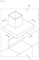
- FIG. 1 is a view illustrating the state that a ventilation apparatus according to an embodiment of the present disclosure is installed in a kitchen.
- a ventilation apparatus 10 may be installed in a space where contaminated air needs to be smoothly exhausted.
- FIG. 1 illustrates that the ventilation apparatus 10 is installed in a kitchen.
- the kitchen may be provided therein with a cooking appliance 1 for cooking food, and air around the cooking appliance 1 may be contaminated during the cooking of the food by the cooking appliance 1.
- the contaminated air rises above the cooking appliance 1 because the temperature of the air is higher than that of surrounding air.
- the ventilation apparatus 10 may be positioned above the cooking appliance 1 such that the contaminated air generated during cooking of the food by the cooking appliance 1 may be discharged to the outside of the kitchen.
- the ventilation apparatus 10 is installed on the wall W of the kitchen or may be installed at a position adjacent to the wall W of the kitchen.
- a storage compartment may be present on one side or opposite sides of the ventilation apparatus 10 depending on the structure of the kitchen.
- a wall “W” of the kitchen or a wall of a storage compartment collectively be referred to "wall”.
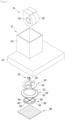
- FIG. 2 is an exploded perspective view of a ventilation apparatus according to an embodiment of the present disclosure
- FIG. 3 is a perspective view taken along line A-A of FIG. 1
- FIG. 4 is a sectional view taken along line B-B of FIG. 1 .
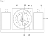
- FIG. 5 is a bottom view of a ventilation apparatus according to an embodiment of the present disclosure.
- FIG. 6 is a sectional view illustrating the arrangement of a suction device and a vortex forming device according to an embodiment of the present disclosure.
- the ventilation apparatus 10 includes a casing that provides a flow passage for guiding the contaminated air, which is suctioned, to the outside.
- the ventilation apparatus 10 further includes a suction device 20 to generate a suction force and a vortex forming device 30 to form a vortex.
- the casing includes a first casing 110 in which the suction device 20 is received and a second casing 112 in which the vortex forming device 30 is received.
- the first casing 110 extends upward from a top surface 115 of the second casing 112.
- a horizontal sectional area of the second casing 112 is formed to be wider than a horizontal sectional area of the first casing 110.
- a front-rear length of the second casing 112 may be formed to be longer than a front-rear length of the first casing 110.
- the left-right width of the second casing 112 may be formed to be longer than a left-right width W1 of the first casing 110.
- a rear surface 110b of the first casing 110 and a rear surface 110a of the second casing 112 form the same plane, and a front surface 112a of the second casing 112 is positioned in front of a front surface 110a of the first casing 110.
- the rear surfaces 110b and 112b of the casings 110 and 112 face the wall and the front surfaces 110a and 112a of the casings 110 and 112 may be opposite surfaces to the rear surfaces 110b and 112b.
- forward direction refers to a direction to face a user from the wall when the user stands while facing the wall W.
- the front face 112a of the second housing 112 is located closer to the user than the front face 110a of the first housing 110 when the user stands facing the wall W.
- the suction device 20 includes a suction fan 210, a suction motor (not illustrated) to rotate the suction fan 210, and a fan housing 220 receiving the suction fan 210 to allow air flow when the suction fan 210 is rotated.
- suction fans 210 may be coupled to opposite sides of one suction motor.
- a portion of the suction device 20 may be received in the first casing 110 and another portion of the suction device 20 may be received in the second casing 112 For example, a portion of the fan housing 220 may be received in the second casing 112.
- the suction device 20 may be received in the first casing 110 in the state that the rotation center C1 of the suction fan 210 is horizontal.
- Opposite sides of the fan housing 220 may be spaced apart from the left and right sides of the first casing 110, when viewed based on FIG. 3 , in the state that the suction device 20 is received in the first casing 110.
- the contaminated air may be introduced into the fan housing 220 from opposite sides of the fan housing 220 and then discharged to the upper portion of the fan housing 220.
- the vortex forming device 30 includes a driving motor 310, a swirler 340 receiving power from the driving motor 310 to rotate, and a flow guide 320 to guide flowing air downward in the process of rotating the swirler 340.
- a flow hole 114 is formed in a bottom surface 113 of the second casing 112 and the swirler 340 may be positioned above the flow hole 114.
- the driving motor 310 may be positioned below the top surface 115 of the second casing 112 and may be positioned above the flow guide 320.
- the vortex forming device 30 As described above, according to the present disclosure, as the vortex forming device 30 is positioned in the second casing 112, when a suction grill 400 to be described later is separated from the second casing 112, a user may easily access the vortex forming device 30, so the vortex forming device 30 may be easily serviced or replaced.
- Lighting units 116 may be positioned at opposite sides of the flow hole 114 in the second casing 112. The lighting units 116 may be turned on when the ventilation apparatus 10 is operated.
- the swirler 340 includes a rotating plate 342 and a plurality of blades 344 arranged along the rim of the rotating plate 342 and spaced apart from each other in a circumferential direction.
- An air passage hole 343 is formed in the rotating plate 342 such that the air rising toward the vortex forming device 30 passes through the rotating plate 342.
- the rotating plate 342 may be provided in the form of a ring.
- Each of the plurality of blades 344 may extend downward from the bottom surface of the rotating plate 342 to push a portion of air in a radial direction of the rotating plate 342 before the air passes through the rotating plate 342.
- each of the plurality of blades 344 may be formed by cutting out a portion of the rotating plate 342 and bending the cut-out portion of the rotating plate 342 at a substantially 90 degrees.
- each of the plurality of blades 344 may be coupled to the rotating plate 342.
- the flow guide 320 may form a space 324 for positioning the swirler 340.
- the flow guide 320 may have a recessed surface 321 recessed upward to form the space 324, when viewed based on FIG. 3 .
- the flow guide 320 may include a through hole 322 through which air may pass.
- the through hole 322 may be provided in the recessed surface 321.
- the swirler 340 may be positioned in the space 324 formed in the flow guide 320. In addition, the swirler 340 may be positioned under the through hole 322.
- the flow guide 320 may include a guide surface 323, which is inclined downward, toward the outer portion of the flow guide 320 from the center of the flow guide 320 such that the vortex is formed under the flow guide 320 by the swirler 340.
- the guide surface 323 may extend such that the recessed surface 321 is rounded toward the outer lower portion of the recessed surface 321.
- the air radially pushed has to flow away from the center of the swirler while flowing downward to form the vortex under the flow guide 320.
- the outer portion of the guide surface 323 may be inclined downward to the outside.
- the flow guide 320 includes the guide surface 323, the flowing direction of the air pushed radially outward from the rotating plate 342 by the blade 344 of the swirler 340 may be changed to be a downward direction by the guide surface 323.
- the air deviating from the guide surface 323 of the flow guide 320 may be inclined downward while flowing.
- air around the flow hole 114 intends to flow into the flow hole 114 of the second casing 112, as well as the contaminated air passing through the flow hole 114.
- the vortex may be formed under the swirler 340 by the flow of air.
- the vortex may be effectively formed under the swirler 340.
- the suction performance (or the exhaust performance) may be improved.
- At least a portion of the driving motor 310 may overlap with the fan housing 220 in the horizontal direction.
- the highest point of the driving motor 310 is positioned higher than the lowest point of the suction device 20 based on the bottom surface 113 of the second casing 112. Therefore, the arrangement of parts in the ventilation apparatus 10 is optimized, and thus the ventilation apparatus 10 is realized in a compact size.
- the flow guide 320 may be positioned at a lower portion of the fan housing 220 to prevent interference between the suction device 20 and the flow guide 320, when a portion of the suction device 20 is disposed in the second casing 112.
- the height of the recessed surface 321 of the flow guide 320 may be lower than the minimum height of the fan housing 220 based on the bottom surface of the second casing 112.
- the swirler 340 may further include a shaft coupling part 346 to be connected with a shaft 312 of the driving motor 310 and at least one connection rib 348 to connect the shaft coupling part 346 to the rotating plate 342.
- the air passage hole 343 may be arranged to overlap with the through holes 322 of the flow guide 320 in the vertical direction such that the contaminated air smoothly flows.
- the shaft coupling part 346 may be positioned in the air passage hole 343 of the rotating plate 342.
- the air flowing in a shaft direction of the swirler 340 may pass through the air passage hole 343 and the through hole 322 without direction change and the distance between the air passage hole 343 and the through hole 322 may be reduced.
- the driving motor 310 may be installed in a mounting part 330 and the mounting part 330 may be, for example, fixed to the flow guide 320.
- the mounting part 330 includes a fixed part 332 fixed to the flow guide 320 and formed in the shape of a circular ring and a support part 334 positioned in an area, in which the fixed part 332 is formed, to support the driving motor 310.
- the shaft 312 of the driving motor 310 may pass through the through hole 322 of the flow guide 320 such that the shaft 312 of the driving motor 310 is coupled to the swirler 340.
- the vortex forming device 30 may further include a suction grill 400 to filter the air suctioned through the flow hole 114.
- the suction grill 400 may have the form of a square grill, for example, and may be coupled to the bottom surface 113 of the second casing 112.
- the suction grill 400 may be coupled to the second casing 112 in a sliding manner.
- the suction grill 400 when the suction grill 400 is provided under the swirler 340, the user is prevented from accessing the swirler 340 in the process of rotating the swirler 340, so the safety of the user is improved.
- the maximum diameter D1 of the flow guide 320 or the diameter of the flow hole 114 in the second casing 112 may be formed to be greater than the width W1 of the first casing 110.
- an amount of air introduced along the flow hole 114 may be increased, and an amount of air dropping along the flow guide 320 by the vortex forming device 30 may be increased, so the vortex may be easily formed.
- the vortex forming device 30 is positioned lower than the rotation center C1 of the suction fan 220.
- the vortex forming device 30 may be positioned close to the flow hole 114 inside the second casing 112. Accordingly, the swirler 340 is positioned closer to the flow hole 114 than the suction fan 220. The swirler 340 has to be positioned close to the flow hole 114 to reduce the height of the vortex forming device 30 and to smoothly form the vortex.
- a first extension line L1 of the shaft 312 of the driving motor 310 may be spaced apart from a second extension line L2, which is virtual and vertical to the rotation center C1 of the suction fan 220).
- the first extension line L1 (or the rotation center of the swirler 340) may be positioned in front of the second extension line L2 based on the wall.
- a third extension line to connect the first extension line L1 of the shaft 312 of the driving motor 310 (or may be called “rotation center of the swirler 340") with the second extension line L2, which is virtual and vertical to the rotation center C1 of the suction fan 220, and may be vertical to the wall W.
- the rotation center of the swirler 340 extends in the vertical direction inside the second casing 112 and the rotation center C1 of the suction fan 220 may extend in the horizontal direction in the first casing 110.
- the first extension line L1 of the shaft 312 of the driving motor 310 (or the rotation center C1 of the swirler 340) is positioned in front of the fan housing 220 with respect to the wall.
- first extension line L1 of the shaft 312 of the driving motor 310 may be positioned outside the first casing 110.
- the first extension line L1 of the shaft 312 of the driving motor 310 may be positioned in front of the front surface 110a of the first casing 110 based on the wall.
- the first extension line L1 of the shaft 312 of the driving motor 310 may be positioned between the suction fan 220 and the front surface 110a of the first casing 110.
- a portion of the flow hole 114 of the second casing 112 overlaps with the fan housing 220 in a vertical direction, and another portion of the flow hole 114 of the second casing 112 does not overlap with the fan housing 220 in the vertical direction.
- a portion of the flow hole 114 of the second casing 112 overlaps with the fan housing 220 in the vertical direction and another portion of the flow hole 114 of the second casing 112 does not overlap with the fan housing 220 in the vertical direction.
- the suction fan 220 overlaps with the swirler 340 in the vertical direction, and the swirler 340 overlaps with the flow hole 114. Accordingly, the flowing length may be prevented from being increased until the air introduced through the flow hole 114 flows to the suction fan 220.
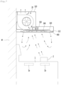
- FIG. 7 is a sectional view illustrating the flow of air, which occurs when the ventilation apparatus operates, according to an embodiment of the present disclosure.
- the suction fan 220 When the suction motor (not illustrated) is turned on, the suction fan 220 is rotated to generate a suction force for suctioning the contaminated air.
- the swirler 340 When the driving motor 310 is turned on, the swirler 340 is rotated so that the air forming the vortex may flow down the ventilation apparatus 10.
- the blade 344 of the swirler 340 pushes the contaminated air, which flows toward the air passage hole 343 of the rotating plate 342, radially outward from the rotating plate 342.
- the flow guide 320 includes the guide surface 323, the flow direction of the air, which is pushed radially outward of the rotating plate 342 by the blade 344 of the swirler 340, is changed downward by the guide surface 323.
- air around the flow hole 114 intends to flow through the flow hole 114, as well as the contaminated air passing through the flow hole 114.
- the vortex may be formed under the swirler 340 by such a flow of air.
- the contaminated air rising upward under the ventilation apparatus 10 may be smoothly suctioned to the ventilation apparatus 10.
- the cooking appliance 1 may include a front heating unit 1b and a rear heating unit 1a spaced apart from each other in front and rear directions when viewed based on FIG. 7 .
- the ventilation apparatus 10 when the ventilation apparatus 10 is positioned above the cooking appliance 1 having the front heating unit 1a and the rear heating unit 1a, at least a portion of the rear heating unit 1a is disposed in overlap with the suction device 20 in the vertical direction.
- the contaminated air which is generated when a cooking material 2 is heated using the rear heating unit 1a, is suctioned to the ventilation apparatus 10 flowing upward substantially vertically through the suction force of the suction device 20.
- the contaminated air generated in the process of heating the cooking material 2 using the front heating unit 1b is inclined toward the upper left portion of the drawing while flowing, by the suction force generated by the suction device 20 and the vortex formed by the swirler 340, as illustrated in FIG. 7 .
- the contaminated air which is generated in the process of heating the cooling material 2 using the front heating unit 1b, is prevented from being away from the wall. Accordingly, the contaminated air may be prevented from being spread into the kitchen equipped with the cooking appliance 1.
- the distance D3 from the first extension line L1 of the shaft 312 of the driving motor 310 to the rear surface 112b of the second casing 112 is formed to longer than the distance D2 from the first extension line L1 of the shaft 312 of the driving motor 310 to the front surface 112a of the second casing 112, so the minimum distance between the flow hole 114 and the wall W may be sufficiently ensured.
- the air discharged from the flow hole 114 while being inclined downward may be prevented from flowing along the wall W. If the air flows downward along the wall, the air exerts an influence on the flame produced by the cooking appliance 1 to prevent the heating efficiency of the cooling appliance 1 from being lowered. Accordingly, this phenomenon may be prevented.
Landscapes
- Engineering & Computer Science (AREA)
- Chemical & Material Sciences (AREA)
- Combustion & Propulsion (AREA)
- Mechanical Engineering (AREA)
- General Engineering & Computer Science (AREA)
- Structures Of Non-Positive Displacement Pumps (AREA)
Description
- The present disclosure relates to a ventilation apparatus.
- The ventilation apparatus is used in factories, homes and restaurants where contaminants are generated in large amounts. Particularly, the ventilation apparatus may be usefully used when a partial pollution source is generated on the floor surface away from an exhaust port, when the exhaust port is difficult to be provided near a pollution source by another installation, or when a pollution source instantly occurs.
-
Korean Unexamined Patent Publication No. 2008-0094412 (published on October 23, 2008 - The local ventilation apparatus suctions contaminants while allowing contaminants to flow using a rotating plate rotated by a driving unit and a swirler including a plurality of blades provided at the rim of the rotating plate.
- The location ventilation apparatus disclosed in the prior art may be located above a cooking appliance in a kitchen and may be exhausted after the contaminated air is suctioned in the course of using the cooking appliance. In this case, the local ventilation apparatus may be installed on the wall of the kitchen or adjacent to the wall.
- The local ventilation apparatus suctions contaminants while allowing contaminants to flow using a rotating plate rotated by a driving unit and a swirler including a plurality of blades arranged at the rim of the rotating plate.
- In the prior art, although the contaminated air may be suctioned using vortex, it may be difficult to form the vortex depending on the installation positions of the ventilation apparatus and thus suction performance may be deteriorated. In other words, when there is a wall or an obstacle on one side of the swirler, it is difficult to form a vortex due to the wall or the obstacle, so suction performance may be deteriorated.
- In addition, the driving unit is located inside an exhaust pipe and the swirler is provided on the rotation shaft of the driving unit, so the installation position of the ventilation apparatus may be restricted. Accordingly, when there are heating units at front and rear portions of a cooling apparatus used in the kitchen like a cooking appliance, the contaminated air may not be effectively suctioned when a cooking material is heated by the heating units.
- In addition, as the swirler, which is rotated at a higher speed, is exposed to the outside, the safety of a user may be not ensured.
-
WO 2011/021760 A1 discloses a range hood including a driving motor, a suction fan and a swirler. The driving motor is disposed above the suction fan. The swirler is disposed below the suction fan. The single driving motor drives both the suction fan and the swirler. -
WO 2012/102462 A2 discloses a ventilation device including a motor member, a suction fan disposed below the motor member and a swirler fan disposed below the suction fan. The single motor member drives both the suction fan and the swirler fan. -
WO 2014/007535 Aldiscloses a ventilation device including a driving unit, and a swirler. The driving unit is provided in a ventilation pipe. The swirler is provided outside the ventilation pipe and below the driving unit. - The present disclosure provides a ventilation apparatus capable of improving the performance of suctioning contaminated air using a swirler forming vortex.
- The present disclosure provides a ventilation apparatus in which contaminated air is prevented from being raised when the contaminated air is generated in the course that a cooling material is cooked by a cooking appliance positioned under the ventilation apparatus, thereby improving the performance of suctioning contaminated air.
- The present disclosure provides a ventilation apparatus capable of facilitating the replacement or the repair of a vortex forming device.
- The present disclosure provides a ventilation apparatus in compact size.
- The objects of the present invention are solved by the features of the independent claim. Preferred embodiments are defined in the dependent claims. Any "aspect", "example" and "embodiment" of the description not falling within the scope of the claims does not form part of the invention and is provided for illustrative purposes only. According to one aspect of the present disclosure, a ventilation apparatus includes a casing, a suction device received in the casing and including a suction fan to generate suction force for suctioning air, and a vortex forming device received in the casing and including a swirler rotated at a lower portion of the casing to generate the vortex and a driving motor to rotate the swirler. The swirler includes a rotating plate having an air passage hole and a plurality of blades arranged along a rim of the rotating plate and spaced apart from each other in a circumferential direction. The vortex forming device is positioned lower than a rotation center of the suction fan, in the casing. The suction device includes a suction motor to rotate the suction fan and a fan housing receiving the suction fan to allow air flow when the suction fan is rotated. The casing includes a first casing in which the suction device is received, and a second casing disposed under the first casing, having a horizontal sectional area wider than a horizontal sectional area of the first casing, and receiving the vortex forming device therein. An uppermost point of the driving motor is positioned higher than a lowermost point of the suction device.
- According to the present embodiment, the casing may include a flow hole to introduce external air, and the swirler may be positioned closer to the flow hole than the suction fan.
- The casing may include a flow hole to introduce external air, the suction fan may be disposed to overlap with the swirler in a vertical direction, and the swirler may be disposed to overlap with the flow hole in the vertical direction.
- The first casing may extend upward from a top surface of the second casing, a rear surface of the first casing and a rear surface of the second casing may form the same plane, the rear surfaces of the first casing and the second casing may face a wall, and a front surface of the second casing may be positioned in front of a front surface of the first casing.
- A rotation center of the swirler may be positioned in front of a vertical line passing through the rotation center of the suction fan, based on the wall.
- The suction device further includes a fan housing to receive the suction fan, and the rotation center of the swirler may be positioned in front of the fan housing, based on the wall.
- An extending line of a rotation center of the swirler may be positioned outside the first casing.
- An extending line of a rotation center of the swirler may be interposed between the fan housing and the first casing.
- A distance from a rotation center of the swirler to a front surface of the second casing may be shorter than a distance from a rotation center of the swirler to a rear surface of the second casing.
- A flow hole may be formed in the second casing, and may have a diameter greater than a left-right width of the first casing.
- The vortex forming device may further include a flow guide to guide air, which flows in a process that the swirler rotates, downward, and the driving motor may be positioned under a top surface of the second casing and positioned above the flow guide.
- A portion of the fan housing may be received inside the second casing.
- The fan housing may be positioned above a flow guide, and at least a portion of the driving motor may overlap with the fan housing in a horizontal direction.
- According to the present disclosure, since the vortex forming device forms vortex under the ventilation apparatus, the suction performance of the suction device may be improved in the process that the suction device suctions the air by suction force thereof.
- In addition, the contaminated air is prevented from being away from the wall in the process of heating the cooking material by the cooking appliance positioned under the ventilation apparatus. Accordingly, the contaminated air may be prevented from being spread throughout a kitchen having the cooking appliance.
- In addition, the air for forming the vortex may be prevented from flowing along the wall.
- In addition, as the suction grill is disposed under the swirler, the safety of the user may be improved by preventing the user from accessing the swirler in the process of the rotation of the swirler.
- In addition, since the uppermost point of the driving motor is positioned higher than the lowermost point of the suction device, based on a bottom surface of the second casing, the arrangement of the parts provided in the ventilation apparatus is optimized, so the ventilation apparatus in compact size may be implemented.
-
-
FIG. 1 is a view illustrating the state that a ventilation apparatus according to an embodiment of the present disclosure is installed in a kitchen. -
FIG. 2 is an exploded perspective view of a ventilation apparatus according to an embodiment of the present disclosure. -
FIG. 3 is a perspective view taken along line A-A ofFIG. 1 . -
FIG. 4 is a sectional view taken along line B-B ofFIG. 1 . -
FIG. 5 is a bottom view of a ventilation apparatus according to an embodiment of the present disclosure. -
FIG. 6 is a sectional view illustrating the arrangement of a suction device and a vortex forming device according to an embodiment of the present disclosure. -
FIG. 7 is a view illustrating an air flow formed when the ventilation apparatus operates according to an embodiment of the present disclosure. - Hereinafter, some embodiments of the present disclosure will be described in detail with reference to the accompanying drawings. It should be noted that when components in the drawings are designated by reference numerals, the same components have the same reference numerals as far as possible even though the components are illustrated in different drawings. Further, in description of embodiments of the present disclosure, when it is determined that detailed descriptions of well-known configurations or functions disturb understanding of the embodiments of the present disclosure, the detailed descriptions will be omitted.
- Also, in the description of the embodiments of the present disclosure, the terms such as first, second, A, B, (a) and (b) may be used. Each of the terms is merely used to distinguish the corresponding component from other components, and does not delimit an essence, an order or a sequence of the corresponding component. It should be understood that when one component is "connected", "coupled" or "joined" to another component, the former may be directly connected or jointed to the latter or may be "connected", coupled" or "joined" to the latter with a third component interposed therebetween.
-
FIG. 1 is a view illustrating the state that a ventilation apparatus according to an embodiment of the present disclosure is installed in a kitchen. - Referring to
FIG. 1 , aventilation apparatus 10 according to an embodiment of the present disclosure may be installed in a space where contaminated air needs to be smoothly exhausted. For example,FIG. 1 illustrates that theventilation apparatus 10 is installed in a kitchen. - The kitchen may be provided therein with a
cooking appliance 1 for cooking food, and air around thecooking appliance 1 may be contaminated during the cooking of the food by thecooking appliance 1. The contaminated air rises above thecooking appliance 1 because the temperature of the air is higher than that of surrounding air. - When the contaminated air rises and stagnates in the kitchen in which the
cooking appliance 1 is placed, there is a problem that the comfort of the kitchen is deteriorated, and smell contained in the contaminated air is absorbed into the kitchen, thereby requiring ventilation for a long time. - The
ventilation apparatus 10 may be positioned above thecooking appliance 1 such that the contaminated air generated during cooking of the food by thecooking appliance 1 may be discharged to the outside of the kitchen. -
Various cooking appliances 1 may be employed, but may be positioned adjacent to the wall of the kitchen. Therefore, to effectively exhaust contaminated air generated in the process of cooking food by thecooking appliance 1, theventilation apparatus 10 is installed on the wall W of the kitchen or may be installed at a position adjacent to the wall W of the kitchen. - A storage compartment may be present on one side or opposite sides of the
ventilation apparatus 10 depending on the structure of the kitchen. - In the present specification, a wall "W" of the kitchen or a wall of a storage compartment collectively be referred to "wall".
-
FIG. 2 is an exploded perspective view of a ventilation apparatus according to an embodiment of the present disclosure,FIG. 3 is a perspective view taken along line A-A ofFIG. 1 , andFIG. 4 is a sectional view taken along line B-B ofFIG. 1 . -
FIG. 5 is a bottom view of a ventilation apparatus according to an embodiment of the present disclosure.FIG. 6 is a sectional view illustrating the arrangement of a suction device and a vortex forming device according to an embodiment of the present disclosure. - Referring to
FIGS. 2 to 6 , theventilation apparatus 10 according to an embodiment of the present disclosure includes a casing that provides a flow passage for guiding the contaminated air, which is suctioned, to the outside. - In addition, the
ventilation apparatus 10 further includes asuction device 20 to generate a suction force and a vortex forming device 30 to form a vortex. - The casing includes a
first casing 110 in which thesuction device 20 is received and asecond casing 112 in which the vortex forming device 30 is received. - The
first casing 110 extends upward from atop surface 115 of thesecond casing 112. - In this case, a horizontal sectional area of the
second casing 112 is formed to be wider than a horizontal sectional area of thefirst casing 110. - For example, when viewed based on
FIG. 3 , a front-rear length of thesecond casing 112 may be formed to be longer than a front-rear length of thefirst casing 110. - In addition, when viewed based on
FIG. 4 , the left-right width of thesecond casing 112 may be formed to be longer than a left-right width W1 of thefirst casing 110. - In addition, a
rear surface 110b of thefirst casing 110 and arear surface 110a of thesecond casing 112 form the same plane, and afront surface 112a of thesecond casing 112 is positioned in front of afront surface 110a of thefirst casing 110. - In the present disclosure, the
rear surfaces casings front surfaces casings rear surfaces - In addition, according to the present disclosure, the term "forward direction" refers to a direction to face a user from the wall when the user stands while facing the wall W.
- The
front face 112a of thesecond housing 112 is located closer to the user than thefront face 110a of thefirst housing 110 when the user stands facing the wall W. - This means that when the
front surface 112a of thesecond casing 112 is positioned farther away from the wall W than thefront surface 110a of thefirst casing 110. - The
suction device 20 includes asuction fan 210, a suction motor (not illustrated) to rotate thesuction fan 210, and afan housing 220 receiving thesuction fan 210 to allow air flow when thesuction fan 210 is rotated. - The present disclosure is not limited thereto, but
suction fans 210 may be coupled to opposite sides of one suction motor. - A portion of the
suction device 20 may be received in thefirst casing 110 and another portion of thesuction device 20 may be received in thesecond casing 112 For example, a portion of thefan housing 220 may be received in thesecond casing 112. - In this case, the
suction device 20 may be received in thefirst casing 110 in the state that the rotation center C1 of thesuction fan 210 is horizontal. - Opposite sides of the
fan housing 220 may be spaced apart from the left and right sides of thefirst casing 110, when viewed based onFIG. 3 , in the state that thesuction device 20 is received in thefirst casing 110. - Accordingly, the contaminated air may be introduced into the
fan housing 220 from opposite sides of thefan housing 220 and then discharged to the upper portion of thefan housing 220. - Meanwhile, an entire portion of the vortex forming device 30 is positioned in the
second casing 112. - The vortex forming device 30 includes a driving
motor 310, aswirler 340 receiving power from the drivingmotor 310 to rotate, and aflow guide 320 to guide flowing air downward in the process of rotating theswirler 340. - A
flow hole 114 is formed in abottom surface 113 of thesecond casing 112 and theswirler 340 may be positioned above theflow hole 114. - The driving
motor 310 may be positioned below thetop surface 115 of thesecond casing 112 and may be positioned above theflow guide 320. - As described above, according to the present disclosure, as the vortex forming device 30 is positioned in the
second casing 112, when asuction grill 400 to be described later is separated from thesecond casing 112, a user may easily access the vortex forming device 30, so the vortex forming device 30 may be easily serviced or replaced. -
Lighting units 116 may be positioned at opposite sides of theflow hole 114 in thesecond casing 112. Thelighting units 116 may be turned on when theventilation apparatus 10 is operated. - The
swirler 340 includes arotating plate 342 and a plurality ofblades 344 arranged along the rim of therotating plate 342 and spaced apart from each other in a circumferential direction. - An
air passage hole 343 is formed in therotating plate 342 such that the air rising toward the vortex forming device 30 passes through therotating plate 342. For example, therotating plate 342 may be provided in the form of a ring. - Each of the plurality of
blades 344 may extend downward from the bottom surface of therotating plate 342 to push a portion of air in a radial direction of therotating plate 342 before the air passes through therotating plate 342. - In addition, for example, each of the plurality of
blades 344 may be formed by cutting out a portion of therotating plate 342 and bending the cut-out portion of therotating plate 342 at a substantially 90 degrees. In addition, each of the plurality ofblades 344 may be coupled to therotating plate 342. - The
flow guide 320 may form aspace 324 for positioning theswirler 340. Theflow guide 320 may have a recessedsurface 321 recessed upward to form thespace 324, when viewed based onFIG. 3 . In addition, theflow guide 320 may include a throughhole 322 through which air may pass. The throughhole 322 may be provided in the recessedsurface 321. - The
swirler 340 may be positioned in thespace 324 formed in theflow guide 320. In addition, theswirler 340 may be positioned under the throughhole 322. - The
flow guide 320 may include aguide surface 323, which is inclined downward, toward the outer portion of theflow guide 320 from the center of theflow guide 320 such that the vortex is formed under theflow guide 320 by theswirler 340. For example, theguide surface 323 may extend such that the recessedsurface 321 is rounded toward the outer lower portion of the recessedsurface 321. - When the
swirler 340 rotates in one direction, theblade 344 of theswirler 340 radially pushes a portion of the contaminated air, which flows toward theair passage hole 343 of therotating plate 342, outward from therotating plate 342. - In this case, the air radially pushed has to flow away from the center of the swirler while flowing downward to form the vortex under the
flow guide 320. - To allow the air pushed radially to flow downward, the outer portion of the
guide surface 323 may be inclined downward to the outside. - As described above, since the
flow guide 320 includes theguide surface 323, the flowing direction of the air pushed radially outward from therotating plate 342 by theblade 344 of theswirler 340 may be changed to be a downward direction by theguide surface 323. - As the air pushed by the
blade 344 of theswirler 340 flows along theguide surface 323 as described above, the air deviating from theguide surface 323 of theflow guide 320 may be inclined downward while flowing. - When the contaminated air passes through the
flow hole 114 of thesecond casing 112, air around theflow hole 114 intends to flow into theflow hole 114 of thesecond casing 112, as well as the contaminated air passing through theflow hole 114. The vortex may be formed under theswirler 340 by the flow of air. - In other words, as the
flow guide 320 guides downward the air flowing in the radial direction of theswirler 340, the vortex may be effectively formed under theswirler 340. - When a portion of the
suction device 20 is disposed in thesecond casing 112, the distance between thesuction device 20 and theflow hole 114 is reduced, so the flow loss of the air may be reduced. The suction performance (or the exhaust performance) may be improved. - When a portion of the
suction device 20 is disposed in thesecond casing 112, at least a portion of the drivingmotor 310 may overlap with thefan housing 220 in the horizontal direction. - The highest point of the driving
motor 310 is positioned higher than the lowest point of thesuction device 20 based on thebottom surface 113 of thesecond casing 112. Therefore, the arrangement of parts in theventilation apparatus 10 is optimized, and thus theventilation apparatus 10 is realized in a compact size. - The
flow guide 320 may be positioned at a lower portion of thefan housing 220 to prevent interference between thesuction device 20 and theflow guide 320, when a portion of thesuction device 20 is disposed in thesecond casing 112. - In other words, the height of the recessed
surface 321 of theflow guide 320 may be lower than the minimum height of thefan housing 220 based on the bottom surface of thesecond casing 112. - The
swirler 340 may further include ashaft coupling part 346 to be connected with ashaft 312 of the drivingmotor 310 and at least oneconnection rib 348 to connect theshaft coupling part 346 to therotating plate 342. - The
air passage hole 343 may be arranged to overlap with the throughholes 322 of theflow guide 320 in the vertical direction such that the contaminated air smoothly flows. Theshaft coupling part 346 may be positioned in theair passage hole 343 of therotating plate 342. - Accordingly, the air flowing in a shaft direction of the
swirler 340 may pass through theair passage hole 343 and the throughhole 322 without direction change and the distance between theair passage hole 343 and the throughhole 322 may be reduced. - The driving
motor 310 may be installed in a mountingpart 330 and the mountingpart 330 may be, for example, fixed to theflow guide 320. - The mounting
part 330 includes a fixed part 332 fixed to theflow guide 320 and formed in the shape of a circular ring and asupport part 334 positioned in an area, in which the fixed part 332 is formed, to support the drivingmotor 310. - The
shaft 312 of the drivingmotor 310 may pass through the throughhole 322 of theflow guide 320 such that theshaft 312 of the drivingmotor 310 is coupled to theswirler 340. - The vortex forming device 30 may further include a
suction grill 400 to filter the air suctioned through theflow hole 114. - The
suction grill 400 may have the form of a square grill, for example, and may be coupled to thebottom surface 113 of thesecond casing 112. For example, thesuction grill 400 may be coupled to thesecond casing 112 in a sliding manner. - According to the present disclosure, when the
suction grill 400 is provided under theswirler 340, the user is prevented from accessing theswirler 340 in the process of rotating theswirler 340, so the safety of the user is improved. - Hereinafter, the arrangement of the
suction device 20 and the vortex forming device 30 will be described in detail. - Referring to
FIG. 4 , the maximum diameter D1 of theflow guide 320 or the diameter of theflow hole 114 in thesecond casing 112 may be formed to be greater than the width W1 of thefirst casing 110. - Accordingly, when the
suction device 20 is operated, an amount of air introduced along theflow hole 114 may be increased, and an amount of air dropping along theflow guide 320 by the vortex forming device 30 may be increased, so the vortex may be easily formed. - Referring to
FIG. 6 , the vortex forming device 30 is positioned lower than the rotation center C1 of thesuction fan 220. - The vortex forming device 30 may be positioned close to the
flow hole 114 inside thesecond casing 112. Accordingly, theswirler 340 is positioned closer to theflow hole 114 than thesuction fan 220. Theswirler 340 has to be positioned close to theflow hole 114 to reduce the height of the vortex forming device 30 and to smoothly form the vortex. - A first extension line L1 of the
shaft 312 of the driving motor 310 (or may be called the rotation center of the swirler 340) may be spaced apart from a second extension line L2, which is virtual and vertical to the rotation center C1 of the suction fan 220). - The first extension line L1 (or the rotation center of the swirler 340) may be positioned in front of the second extension line L2 based on the wall.
- A third extension line to connect the first extension line L1 of the
shaft 312 of the driving motor 310 (or may be called "rotation center of theswirler 340") with the second extension line L2, which is virtual and vertical to the rotation center C1 of thesuction fan 220, and may be vertical to the wall W. - The rotation center of the
swirler 340 extends in the vertical direction inside thesecond casing 112 and the rotation center C1 of thesuction fan 220 may extend in the horizontal direction in thefirst casing 110. - The first extension line L1 of the
shaft 312 of the driving motor 310 (or the rotation center C1 of the swirler 340) is positioned in front of thefan housing 220 with respect to the wall. - The present disclosure is not limited, but the first extension line L1 of the
shaft 312 of the drivingmotor 310 may be positioned outside thefirst casing 110. For example, the first extension line L1 of theshaft 312 of the drivingmotor 310 may be positioned in front of thefront surface 110a of thefirst casing 110 based on the wall. - As another example, the first extension line L1 of the
shaft 312 of the drivingmotor 310 may be positioned between thesuction fan 220 and thefront surface 110a of thefirst casing 110. - A portion of the
flow hole 114 of thesecond casing 112 overlaps with thefan housing 220 in a vertical direction, and another portion of theflow hole 114 of thesecond casing 112 does not overlap with thefan housing 220 in the vertical direction. - According to the above arrangement, a portion of the
flow hole 114 of thesecond casing 112 overlaps with thefan housing 220 in the vertical direction and another portion of theflow hole 114 of thesecond casing 112 does not overlap with thefan housing 220 in the vertical direction. - At this time, the
suction fan 220 overlaps with theswirler 340 in the vertical direction, and theswirler 340 overlaps with theflow hole 114. Accordingly, the flowing length may be prevented from being increased until the air introduced through theflow hole 114 flows to thesuction fan 220. -
FIG. 7 is a sectional view illustrating the flow of air, which occurs when the ventilation apparatus operates, according to an embodiment of the present disclosure. - Referring to
FIGS. 1 to 7 , when an operation command of theventilation apparatus 10 is input, the suction motor (not illustrated) and the drivingmotor 310 are turned on. - When the suction motor (not illustrated) is turned on, the
suction fan 220 is rotated to generate a suction force for suctioning the contaminated air. - When the driving
motor 310 is turned on, theswirler 340 is rotated so that the air forming the vortex may flow down theventilation apparatus 10. - Specifically, when the
swirler 340 rotates in one direction, theblade 344 of theswirler 340 pushes the contaminated air, which flows toward theair passage hole 343 of therotating plate 342, radially outward from therotating plate 342. - Since the
flow guide 320 includes theguide surface 323, the flow direction of the air, which is pushed radially outward of therotating plate 342 by theblade 344 of theswirler 340, is changed downward by theguide surface 323. - As the air pushed by the
blade 344 as described above flows along theguide surface 323, the air, which is to form the vortex, deviates from theguide surface 323, is discharged through theflow hole 114, is inclined downward while flowing. - When the contaminated air passes through the
flow hole 114 of thesecond casing 112, air around theflow hole 114 intends to flow through theflow hole 114, as well as the contaminated air passing through theflow hole 114. The vortex may be formed under theswirler 340 by such a flow of air. - According to the present disclosure, when the vortex is formed under the
swirler 340 by theswirler 340 and theflow guide 320, the contaminated air rising upward under theventilation apparatus 10 may be smoothly suctioned to theventilation apparatus 10. - Meanwhile, the
cooking appliance 1 may include afront heating unit 1b and a rear heating unit 1a spaced apart from each other in front and rear directions when viewed based onFIG. 7 . - In general, when the
ventilation apparatus 10 is positioned above thecooking appliance 1 having the front heating unit 1a and the rear heating unit 1a, at least a portion of the rear heating unit 1a is disposed in overlap with thesuction device 20 in the vertical direction. - Therefore, the contaminated air, which is generated when a
cooking material 2 is heated using the rear heating unit 1a, is suctioned to theventilation apparatus 10 flowing upward substantially vertically through the suction force of thesuction device 20. - Meanwhile, as described above, as the first extension line L1 of the
shaft 312 of the drivingmotor 310 is positioned in front of thefan housing 220 as described above, the contaminated air generated in the process of heating thecooking material 2 using thefront heating unit 1b is inclined toward the upper left portion of the drawing while flowing, by the suction force generated by thesuction device 20 and the vortex formed by theswirler 340, as illustrated inFIG. 7 . - In addition, the contaminated air, which is generated in the process of heating the
cooling material 2 using thefront heating unit 1b, is prevented from being away from the wall. Accordingly, the contaminated air may be prevented from being spread into the kitchen equipped with thecooking appliance 1. - In addition, according to the present disclosure, the distance D3 from the first extension line L1 of the
shaft 312 of the drivingmotor 310 to therear surface 112b of thesecond casing 112 is formed to longer than the distance D2 from the first extension line L1 of theshaft 312 of the drivingmotor 310 to thefront surface 112a of thesecond casing 112, so the minimum distance between theflow hole 114 and the wall W may be sufficiently ensured. - The air discharged from the
flow hole 114 while being inclined downward may be prevented from flowing along the wall W. If the air flows downward along the wall, the air exerts an influence on the flame produced by thecooking appliance 1 to prevent the heating efficiency of the coolingappliance 1 from being lowered. Accordingly, this phenomenon may be prevented. - Although the above description of the embodiment of the present disclosure has been made in that all components are integrated into one part or operate as one part, the present disclosure is not limited thereto. In other words, one or more components may be selectively combined with each other to operate within the scope of the present disclosure. In addition, the terms such as "comprise", "have", or "include" refers to the presence of a relevant component unless specified otherwise, and should be interpreted as further including another component without excluding the another component. Unless otherwise defined herein, all the terms used herein, which include technical or scientific terms, may have the same meaning that is generally understood by a person skilled in the art. It will be further understood that terms used herein should be interpreted as having a meaning that is consistent with their meaning in the context of this disclosure and the relevant art and will not be interpreted in an idealized or overly formal sense unless expressly so defined in the present disclosure.
Claims (13)
- A ventilation apparatus comprising:a casing (110, 112);a suction device (20) received in the casing (110, 112) and including a suction fan (210) to generate suction force for suctioning air; anda vortex forming device (30) received in the casing (110, 112) and including a swirler (340) rotated at a lower portion of the casing (110, 112) to generate the vortex and a driving motor (310) to rotate the swirler (340),wherein the swirler (340) includes a rotating plate (342) having an air passage hole (343) and a plurality of blades (344) arranged along a rim of the rotating plate (342) and spaced apart from each other in a circumferential direction, andwherein the vortex forming device (30) is positioned lower than a rotation center (C1) of the suction fan (210), in the casing (110, 112),characterized in thatthe suction device (20) includes a suction motor to rotate the suction fan (210) and a fan housing (220) receiving the suction fan (210) to allow air flow when the suction fan (210) is rotated,wherein the casing (110, 112) includes:a first casing (110) in which the suction device (20) is received; anda second casing (112) disposed under the first casing (110), having a horizontal sectional area wider than a horizontal sectional area of the first casing (110), and receiving the vortex forming device (30) therein, andan uppermost point of the driving motor (310) is positioned higher than a lowermost point of the suction device (20).
- The ventilation apparatus of claim 1, wherein the casing (110, 112) includes a flow hole (114) to introduce external air, and
wherein the swirler (340) is positioned closer to the flow hole (114) than the suction fan (210). - The ventilation apparatus of claim 1, wherein the casing (110, 112) includes a flow hole (114) to introduce external air,wherein the suction fan (210) is disposed to overlap with the swirler (340) in a vertical direction, andwherein the swirler (340) is disposed to overlap with the flow hole (114) in the vertical direction.
- The ventilation apparatus of claim 1, wherein the first casing (110) extends upward from a top surface of the second casing (112),wherein a rear surface of the first casing (110) and a rear surface of the second casing (112) form the same plane,wherein the rear surfaces of the first casing (110) and the second casing (112) face a wall, andwherein a front surface (112a) of the second casing (112) is positioned farther away from the wall (W) than the front surface (1 10a) of the first casing (110).
- The ventilation apparatus of claim 4, wherein a distance between a rotation center of the swirler (340) and the wall (W) is greater than a distance between a rotation center (C1) of the suction fan (210) and the wall (W).
- The ventilation apparatus of claim 5, wherein the suction device (20) further includes: a fan housing (220) to receive the suction fan (210), and
wherein a distance between the rotation center of the swirler (340) and the wall (W) is greater than a distance between the fan housing (220) and the wall (W). - The ventilation apparatus of claim 1, wherein an extending line of a rotation center of the swirler (340) is positioned outside the first casing (110).
- The ventilation apparatus of claim 1, wherein an extending line of a rotation center of the swirler (340) is interposed between the fan housing (220) and the first casing (110).
- The ventilation apparatus of claim 1, wherein a distance from a rotation center of the swirler (340) to a front surface of the second casing (112) is shorter than a distance from a rotation center of the swirler (340) to a rear surface of the second casing (112).
- The ventilation apparatus of claim 1, wherein a flow hole (114) is formed in the second casing (112), and
wherein the flow hole (114) has a diameter greater than a left-right width of the first casing (110). - The ventilation apparatus of claim 1, wherein the vortex forming device (30) further includes:a flow guide (320) to guide air, which flows in a process that the swirler (340) rotates, downward, andwherein the driving motor (310) is positioned under a top surface of the second casing (112) and positioned above the flow guide (320).
- The ventilation apparatus of claim 1, wherein the suction device (20) further includes a fan housing (220) to receive the suction fan (210), and
wherein a portion of the fan housing (220) is received inside the second casing (112). - The ventilation apparatus of claim 12, wherein the fan housing (220) is positioned above a flow guide (320), and
wherein at least a portion of the driving motor (310) overlaps with the fan housing (220) in a horizontal direction.
Applications Claiming Priority (2)
| Application Number | Priority Date | Filing Date | Title |
|---|---|---|---|
| KR1020160164787A KR102111328B1 (en) | 2016-12-06 | 2016-12-06 | Ventilating apparatus |
| PCT/KR2017/014053 WO2018105966A1 (en) | 2016-12-06 | 2017-12-04 | Ventilation apparatus |
Publications (3)
| Publication Number | Publication Date |
|---|---|
| EP3553399A1 EP3553399A1 (en) | 2019-10-16 |
| EP3553399A4 EP3553399A4 (en) | 2020-08-12 |
| EP3553399B1 true EP3553399B1 (en) | 2025-02-05 |
Family
ID=62491499
Family Applications (1)
| Application Number | Title | Priority Date | Filing Date |
|---|---|---|---|
| EP17879025.9A Active EP3553399B1 (en) | 2016-12-06 | 2017-12-04 | Ventilation apparatus |
Country Status (4)
| Country | Link |
|---|---|
| US (1) | US11280501B2 (en) |
| EP (1) | EP3553399B1 (en) |
| KR (1) | KR102111328B1 (en) |
| WO (1) | WO2018105966A1 (en) |
Families Citing this family (3)
| Publication number | Priority date | Publication date | Assignee | Title |
|---|---|---|---|---|
| ES3009526T3 (en) * | 2018-09-27 | 2025-03-27 | Elica Spa | Assembly for mounting a kitchen extractor hood and method executing said mounting |
| KR102059802B1 (en) * | 2019-05-24 | 2019-12-27 | 주식회사 토네이도시스템즈 | Range hood with vortex fan |
| US20210396394A1 (en) * | 2020-06-19 | 2021-12-23 | Dynamic HVAC Supply Ltd. | Kitchen exhaust recovery system |
Family Cites Families (24)
| Publication number | Priority date | Publication date | Assignee | Title |
|---|---|---|---|---|
| DE19613513A1 (en) * | 1996-04-04 | 1997-10-09 | Roehl Hager Hannelore | Process for limiting, detecting and extracting haze, dust or the like and device for carrying out the process |
| KR20000051144A (en) * | 1999-01-19 | 2000-08-16 | 구자홍 | Ventilation apparatus of over the range |
| KR100556835B1 (en) | 2004-08-23 | 2006-03-10 | 엘지전자 주식회사 | Kitchen Exhaust Hood |
| JP4720556B2 (en) | 2006-03-14 | 2011-07-13 | パナソニック株式会社 | Range food |
| JP2008196801A (en) * | 2007-02-14 | 2008-08-28 | Matsushita Electric Ind Co Ltd | Range food |
| KR100873521B1 (en) | 2007-04-20 | 2008-12-15 | 포항공과대학교 산학협력단 | Vortex Type Local Exhaust System |
| KR100854449B1 (en) | 2007-05-25 | 2008-08-26 | (주)이지에스 | Range hood with improved exhaust efficiency |
| EP2196737B1 (en) * | 2008-12-10 | 2013-07-03 | Electrolux Home Products Corporation N.V. | Suction Hood |
| EP2196738B1 (en) * | 2008-12-10 | 2013-10-23 | Electrolux Home Products Corporation N.V. | Suction hood |
| KR20110020157A (en) * | 2009-08-21 | 2011-03-02 | 유한회사 대동 | Range hood with swirler |
| WO2011021760A1 (en) * | 2009-08-21 | 2011-02-24 | 유한회사 대동 | Range cooker hood employing a swirler |
| WO2012102462A2 (en) * | 2011-01-26 | 2012-08-02 | (주)지텍 | Local exhaust device and irish kitchen system having same |
| KR20120086642A (en) * | 2011-01-26 | 2012-08-03 | (주)지텍 | Local Ventilator Device and island type kitchen system having its |
| KR101335662B1 (en) * | 2012-04-03 | 2013-12-03 | 주식회사트라이애드 | Exhaust system with built-in rotation body |
| KR101444338B1 (en) * | 2012-07-05 | 2014-10-07 | 김지하 | Local ventilator with swirler |
| KR101606862B1 (en) | 2013-09-04 | 2016-03-28 | 김지하 | Local ventilator having swirler and guide member |
| KR102247218B1 (en) * | 2014-11-21 | 2021-05-04 | 엘지전자 주식회사 | Discharging apparatus and cooking device |
| KR101625828B1 (en) * | 2014-12-08 | 2016-05-31 | 주식회사 토네이도시스템즈 | Vantilator module with swilrer fan |
| KR101709278B1 (en) * | 2015-01-20 | 2017-02-23 | 김지하 | Local ventilator |
| KR102318830B1 (en) | 2015-03-19 | 2021-10-28 | 엘지전자 주식회사 | Cooking device and discharging apparatus |
| WO2016148468A1 (en) * | 2015-03-19 | 2016-09-22 | Lg Electronics Inc. | Cooking device |
| KR20160069500A (en) * | 2015-12-16 | 2016-06-16 | 주식회사 토네이도시스템즈 | Vantilator module with swilrer fan |
| PT3455558T (en) * | 2016-07-07 | 2020-05-06 | B S Service S R L | Kitchen extractor hood with vortex flow |
| AU2016413663A1 (en) * | 2016-07-07 | 2019-01-17 | B.S. Service S.R.L. | Kitchen extractor hood with directional flow |
-
2016
- 2016-12-06 KR KR1020160164787A patent/KR102111328B1/en active Active
-
2017
- 2017-12-04 US US16/466,329 patent/US11280501B2/en active Active
- 2017-12-04 WO PCT/KR2017/014053 patent/WO2018105966A1/en not_active Ceased
- 2017-12-04 EP EP17879025.9A patent/EP3553399B1/en active Active
Also Published As
| Publication number | Publication date |
|---|---|
| WO2018105966A1 (en) | 2018-06-14 |
| KR20180064662A (en) | 2018-06-15 |
| EP3553399A1 (en) | 2019-10-16 |
| US20190309958A1 (en) | 2019-10-10 |
| EP3553399A4 (en) | 2020-08-12 |
| US11280501B2 (en) | 2022-03-22 |
| KR102111328B1 (en) | 2020-05-15 |
Similar Documents
| Publication | Publication Date | Title |
|---|---|---|
| EP3550212B1 (en) | Cookware and exhaust device | |
| KR102076668B1 (en) | An indoor unit for an air conditioner | |
| CN107923631B (en) | Combined unit with cooking area and fume extraction | |
| EP3271657B1 (en) | Cooking device | |
| EP3553399B1 (en) | Ventilation apparatus | |
| US20180209662A1 (en) | Combined device with cooking surface and fume extractor | |
| KR102247218B1 (en) | Discharging apparatus and cooking device | |
| KR20180006641A (en) | Hood and cooking device | |
| EP3779284B1 (en) | Local exhaust device | |
| KR102206327B1 (en) | Dehumidifier | |
| CN107894014A (en) | Heating device | |
| EP3030047B1 (en) | Over-the-range microwave oven with an integrated duct module | |
| JP6304388B2 (en) | Dehumidifier | |
| KR102318830B1 (en) | Cooking device and discharging apparatus | |
| EP2384136B1 (en) | Base for a food processor | |
| JP2010277906A (en) | Induction heating cooker | |
| EP4375581B1 (en) | Cookware and exhaust device | |
| EP4325124A1 (en) | Range hood and cooking apparatus having same | |
| JP2013026167A (en) | Induction heating cooker | |
| EP3684141B1 (en) | Cooking device | |
| KR20120066487A (en) | A cooking appliance | |
| KR20190041808A (en) | Air conditioner | |
| JP4973388B2 (en) | Induction heating cooker | |
| EP2312245A2 (en) | Domestic electrical appliance | |
| JP5538130B2 (en) | Electromagnetic induction heating cooker |
Legal Events
| Date | Code | Title | Description |
|---|---|---|---|
| STAA | Information on the status of an ep patent application or granted ep patent |
Free format text: STATUS: THE INTERNATIONAL PUBLICATION HAS BEEN MADE |
|
| PUAI | Public reference made under article 153(3) epc to a published international application that has entered the european phase |
Free format text: ORIGINAL CODE: 0009012 |
|
| STAA | Information on the status of an ep patent application or granted ep patent |
Free format text: STATUS: REQUEST FOR EXAMINATION WAS MADE |
|
| 17P | Request for examination filed |
Effective date: 20190703 |
|
| AK | Designated contracting states |
Kind code of ref document: A1 Designated state(s): AL AT BE BG CH CY CZ DE DK EE ES FI FR GB GR HR HU IE IS IT LI LT LU LV MC MK MT NL NO PL PT RO RS SE SI SK SM TR |
|
| AX | Request for extension of the european patent |
Extension state: BA ME |
|
| DAV | Request for validation of the european patent (deleted) | ||
| DAX | Request for extension of the european patent (deleted) | ||
| A4 | Supplementary search report drawn up and despatched |
Effective date: 20200710 |
|
| RIC1 | Information provided on ipc code assigned before grant |
Ipc: F24F 7/007 20060101AFI20200706BHEP Ipc: F24F 13/10 20060101ALI20200706BHEP Ipc: F24C 15/20 20060101ALI20200706BHEP Ipc: F24F 13/20 20060101ALI20200706BHEP |
|
| STAA | Information on the status of an ep patent application or granted ep patent |
Free format text: STATUS: EXAMINATION IS IN PROGRESS |
|
| 17Q | First examination report despatched |
Effective date: 20220329 |
|
| GRAP | Despatch of communication of intention to grant a patent |
Free format text: ORIGINAL CODE: EPIDOSNIGR1 |
|
| STAA | Information on the status of an ep patent application or granted ep patent |
Free format text: STATUS: GRANT OF PATENT IS INTENDED |
|
| INTG | Intention to grant announced |
Effective date: 20240723 |
|
| GRAS | Grant fee paid |
Free format text: ORIGINAL CODE: EPIDOSNIGR3 |
|
| GRAA | (expected) grant |
Free format text: ORIGINAL CODE: 0009210 |
|
| STAA | Information on the status of an ep patent application or granted ep patent |
Free format text: STATUS: THE PATENT HAS BEEN GRANTED |
|
| AK | Designated contracting states |
Kind code of ref document: B1 Designated state(s): AL AT BE BG CH CY CZ DE DK EE ES FI FR GB GR HR HU IE IS IT LI LT LU LV MC MK MT NL NO PL PT RO RS SE SI SK SM TR |
|
| REG | Reference to a national code |
Ref country code: GB Ref legal event code: FG4D |
|
| REG | Reference to a national code |
Ref country code: CH Ref legal event code: EP |
|
| REG | Reference to a national code |
Ref country code: IE Ref legal event code: FG4D |
|
| REG | Reference to a national code |
Ref country code: DE Ref legal event code: R096 Ref document number: 602017087656 Country of ref document: DE |
|
| REG | Reference to a national code |
Ref country code: NL Ref legal event code: MP Effective date: 20250205 |
|
| PG25 | Lapsed in a contracting state [announced via postgrant information from national office to epo] |
Ref country code: RS Free format text: LAPSE BECAUSE OF FAILURE TO SUBMIT A TRANSLATION OF THE DESCRIPTION OR TO PAY THE FEE WITHIN THE PRESCRIBED TIME-LIMIT Effective date: 20250505 |
|
| PG25 | Lapsed in a contracting state [announced via postgrant information from national office to epo] |
Ref country code: FI Free format text: LAPSE BECAUSE OF FAILURE TO SUBMIT A TRANSLATION OF THE DESCRIPTION OR TO PAY THE FEE WITHIN THE PRESCRIBED TIME-LIMIT Effective date: 20250205 |
|
| PG25 | Lapsed in a contracting state [announced via postgrant information from national office to epo] |
Ref country code: PL Free format text: LAPSE BECAUSE OF FAILURE TO SUBMIT A TRANSLATION OF THE DESCRIPTION OR TO PAY THE FEE WITHIN THE PRESCRIBED TIME-LIMIT Effective date: 20250205 |
|
| PG25 | Lapsed in a contracting state [announced via postgrant information from national office to epo] |
Ref country code: ES Free format text: LAPSE BECAUSE OF FAILURE TO SUBMIT A TRANSLATION OF THE DESCRIPTION OR TO PAY THE FEE WITHIN THE PRESCRIBED TIME-LIMIT Effective date: 20250205 |
|
| REG | Reference to a national code |
Ref country code: LT Ref legal event code: MG9D |
|
| PG25 | Lapsed in a contracting state [announced via postgrant information from national office to epo] |
Ref country code: IS Free format text: LAPSE BECAUSE OF FAILURE TO SUBMIT A TRANSLATION OF THE DESCRIPTION OR TO PAY THE FEE WITHIN THE PRESCRIBED TIME-LIMIT Effective date: 20250605 Ref country code: NO Free format text: LAPSE BECAUSE OF FAILURE TO SUBMIT A TRANSLATION OF THE DESCRIPTION OR TO PAY THE FEE WITHIN THE PRESCRIBED TIME-LIMIT Effective date: 20250505 |
|
| PG25 | Lapsed in a contracting state [announced via postgrant information from national office to epo] |
Ref country code: NL Free format text: LAPSE BECAUSE OF FAILURE TO SUBMIT A TRANSLATION OF THE DESCRIPTION OR TO PAY THE FEE WITHIN THE PRESCRIBED TIME-LIMIT Effective date: 20250205 |
|
| PG25 | Lapsed in a contracting state [announced via postgrant information from national office to epo] |
Ref country code: HR Free format text: LAPSE BECAUSE OF FAILURE TO SUBMIT A TRANSLATION OF THE DESCRIPTION OR TO PAY THE FEE WITHIN THE PRESCRIBED TIME-LIMIT Effective date: 20250205 |
|
| PG25 | Lapsed in a contracting state [announced via postgrant information from national office to epo] |
Ref country code: LV Free format text: LAPSE BECAUSE OF FAILURE TO SUBMIT A TRANSLATION OF THE DESCRIPTION OR TO PAY THE FEE WITHIN THE PRESCRIBED TIME-LIMIT Effective date: 20250205 Ref country code: PT Free format text: LAPSE BECAUSE OF FAILURE TO SUBMIT A TRANSLATION OF THE DESCRIPTION OR TO PAY THE FEE WITHIN THE PRESCRIBED TIME-LIMIT Effective date: 20250605 |
|
| PG25 | Lapsed in a contracting state [announced via postgrant information from national office to epo] |
Ref country code: BG Free format text: LAPSE BECAUSE OF FAILURE TO SUBMIT A TRANSLATION OF THE DESCRIPTION OR TO PAY THE FEE WITHIN THE PRESCRIBED TIME-LIMIT Effective date: 20250205 Ref country code: GR Free format text: LAPSE BECAUSE OF FAILURE TO SUBMIT A TRANSLATION OF THE DESCRIPTION OR TO PAY THE FEE WITHIN THE PRESCRIBED TIME-LIMIT Effective date: 20250506 |
|
| REG | Reference to a national code |
Ref country code: AT Ref legal event code: MK05 Ref document number: 1764943 Country of ref document: AT Kind code of ref document: T Effective date: 20250205 |
|
| PG25 | Lapsed in a contracting state [announced via postgrant information from national office to epo] |
Ref country code: SE Free format text: LAPSE BECAUSE OF FAILURE TO SUBMIT A TRANSLATION OF THE DESCRIPTION OR TO PAY THE FEE WITHIN THE PRESCRIBED TIME-LIMIT Effective date: 20250205 |
|
| PG25 | Lapsed in a contracting state [announced via postgrant information from national office to epo] |
Ref country code: SM Free format text: LAPSE BECAUSE OF FAILURE TO SUBMIT A TRANSLATION OF THE DESCRIPTION OR TO PAY THE FEE WITHIN THE PRESCRIBED TIME-LIMIT Effective date: 20250205 |
|
| PG25 | Lapsed in a contracting state [announced via postgrant information from national office to epo] |
Ref country code: DK Free format text: LAPSE BECAUSE OF FAILURE TO SUBMIT A TRANSLATION OF THE DESCRIPTION OR TO PAY THE FEE WITHIN THE PRESCRIBED TIME-LIMIT Effective date: 20250205 |
|
| PG25 | Lapsed in a contracting state [announced via postgrant information from national office to epo] |
Ref country code: AT Free format text: LAPSE BECAUSE OF FAILURE TO SUBMIT A TRANSLATION OF THE DESCRIPTION OR TO PAY THE FEE WITHIN THE PRESCRIBED TIME-LIMIT Effective date: 20250205 |
|
| PG25 | Lapsed in a contracting state [announced via postgrant information from national office to epo] |
Ref country code: EE Free format text: LAPSE BECAUSE OF FAILURE TO SUBMIT A TRANSLATION OF THE DESCRIPTION OR TO PAY THE FEE WITHIN THE PRESCRIBED TIME-LIMIT Effective date: 20250205 Ref country code: CZ Free format text: LAPSE BECAUSE OF FAILURE TO SUBMIT A TRANSLATION OF THE DESCRIPTION OR TO PAY THE FEE WITHIN THE PRESCRIBED TIME-LIMIT Effective date: 20250205 |
|
| PG25 | Lapsed in a contracting state [announced via postgrant information from national office to epo] |
Ref country code: RO Free format text: LAPSE BECAUSE OF FAILURE TO SUBMIT A TRANSLATION OF THE DESCRIPTION OR TO PAY THE FEE WITHIN THE PRESCRIBED TIME-LIMIT Effective date: 20250205 |
|
| PG25 | Lapsed in a contracting state [announced via postgrant information from national office to epo] |
Ref country code: SK Free format text: LAPSE BECAUSE OF FAILURE TO SUBMIT A TRANSLATION OF THE DESCRIPTION OR TO PAY THE FEE WITHIN THE PRESCRIBED TIME-LIMIT Effective date: 20250205 |
|
| REG | Reference to a national code |
Ref country code: DE Ref legal event code: R097 Ref document number: 602017087656 Country of ref document: DE |
|
| PLBE | No opposition filed within time limit |
Free format text: ORIGINAL CODE: 0009261 |
|
| STAA | Information on the status of an ep patent application or granted ep patent |
Free format text: STATUS: NO OPPOSITION FILED WITHIN TIME LIMIT |
|
| PGFP | Annual fee paid to national office [announced via postgrant information from national office to epo] |
Ref country code: DE Payment date: 20251105 Year of fee payment: 9 |
|
| 26N | No opposition filed |
Effective date: 20251106 |
|
| PGFP | Annual fee paid to national office [announced via postgrant information from national office to epo] |
Ref country code: IT Payment date: 20251106 Year of fee payment: 9 |
|
| PGFP | Annual fee paid to national office [announced via postgrant information from national office to epo] |
Ref country code: FR Payment date: 20251111 Year of fee payment: 9 |