JP2017190896A - Heat exchanger - Google Patents
Heat exchanger Download PDFInfo
- Publication number
- JP2017190896A JP2017190896A JP2016079796A JP2016079796A JP2017190896A JP 2017190896 A JP2017190896 A JP 2017190896A JP 2016079796 A JP2016079796 A JP 2016079796A JP 2016079796 A JP2016079796 A JP 2016079796A JP 2017190896 A JP2017190896 A JP 2017190896A
- Authority
- JP
- Japan
- Prior art keywords
- refrigerant
- distribution
- tank
- distribution tank
- heat exchanger
- Prior art date
- Legal status (The legal status is an assumption and is not a legal conclusion. Google has not performed a legal analysis and makes no representation as to the accuracy of the status listed.)
- Pending
Links
Images

Landscapes
- Air-Conditioning For Vehicles (AREA)
- Details Of Heat-Exchange And Heat-Transfer (AREA)
- Heat-Exchange Devices With Radiators And Conduit Assemblies (AREA)
Abstract
【課題】冷媒が相対的に低流量の場合においても、冷媒との熱交換後の空気の温度分布を均一に保つことができる熱交換器を提供する。【解決手段】熱交換器としてのエバポレータ40は、積層配列される複数のチューブ45A,45Bと、チューブ内部に設けられ、冷媒を流す複数の冷媒通過孔50と、冷媒の流れの上流側にて複数のチューブと接続され、供給された冷媒を複数のチューブに分配する分配タンク41A,42B,43A,44Bと、冷媒の流れの下流側にて複数のチューブと接続され、複数のチューブを流れた前記冷媒を集合させる集合タンク42A,41B,44A,43Bと、分配タンク41A,42B,43A,44Bに設けられ、冷媒が相対的に低流量のとき複数の冷媒通過孔に対し冷媒の供給量を一部に偏らせる分配偏向部53と、を備える。【選択図】図4Provided is a heat exchanger that can maintain a uniform temperature distribution of air after heat exchange with a refrigerant even when the refrigerant has a relatively low flow rate. An evaporator as a heat exchanger includes a plurality of tubes arranged in a stack, a plurality of refrigerant passage holes provided inside the tubes, and upstream of the refrigerant flow. The distribution tanks 41A, 42B, 43A, 44B connected to a plurality of tubes and distributing the supplied refrigerant to the plurality of tubes, and connected to the plurality of tubes on the downstream side of the refrigerant flow, flowed through the plurality of tubes. Provided in the collecting tanks 42A, 41B, 44A, and 43B for collecting the refrigerant and the distribution tanks 41A, 42B, 43A, and 44B, the amount of refrigerant supplied to the plurality of refrigerant passage holes when the refrigerant is at a relatively low flow rate. And a distribution deflecting portion 53 that biases to a part. [Selection] Figure 4
Description
本発明は、チューブの内部を流れる冷媒と、チューブの外部を流れる空気との間で熱交換を行う熱交換器に関する。 The present invention relates to a heat exchanger that performs heat exchange between a refrigerant flowing inside a tube and air flowing outside the tube.
車両用の空調装置のエバポレータなどに適用される熱交換器において、例えば熱交換器を風上側2ブロック、風下側2ブロックの合計4ブロックに分けて、内部を流れる冷媒の分配を均一化し、冷房性能の向上及び吹き出し空気の均一化を図ったものが知られている(例えば特許文献1参照)。 In a heat exchanger applied to an evaporator of a vehicle air conditioner or the like, for example, the heat exchanger is divided into a total of 4 blocks, 2 blocks on the leeward side and 2 blocks on the leeward side, so that the distribution of the refrigerant flowing in the interior is made uniform. What improved the performance and made uniform the blown air is known (see, for example, Patent Document 1).
このような熱交換器の4ブロックの構造では、夏場での高速走行時など、比較的熱負荷が高く冷媒流量が高い場合においては、冷媒圧力損失の低減効果により高性能化が可能となる。一方で、冬場など、外気温度が低い場合は、通常車両用空調装置に設けられている機械式膨張弁の前後の差圧が小さくなり、エバポレータの能力に応じた冷媒流量を流すことができなくなる。 With such a four-block structure of the heat exchanger, when the heat load is relatively high and the refrigerant flow rate is high, such as during high-speed running in summer, high performance can be achieved by reducing the refrigerant pressure loss. On the other hand, when the outside air temperature is low, such as in winter, the differential pressure before and after the mechanical expansion valve usually provided in the vehicle air conditioner becomes small, and it becomes impossible to flow the refrigerant flow according to the capacity of the evaporator. .
このように冷媒が相対的に低流量の場合においては、エバポレータの途中で冷媒の蒸発が完了してしまい、チューブの積層方向に沿って冷媒の温度差が拡大し、最終的に冷媒との熱交換後の空気の温度分布が均一とはならない場合がある。これにより、除湿性能の偏り、さらにはその結果、窓曇り防止性能の低下(例えば、助手席側の窓曇りだけが晴れて、運転席側の窓曇りは晴れない、など)をもたらしてしまう虞がある。また、空調時においても、吹出口の温度コントロール性能の低下を招く虞がある。 Thus, when the refrigerant has a relatively low flow rate, the evaporation of the refrigerant is completed in the middle of the evaporator, the temperature difference of the refrigerant expands along the tube stacking direction, and finally the heat from the refrigerant The temperature distribution of the air after replacement may not be uniform. As a result, the dehumidification performance may be biased, and as a result, the window fogging prevention performance may be deteriorated (for example, only the window fogging on the passenger side is clear and the window fogging on the driver side is not clear). There is. Further, even during air conditioning, there is a possibility that the temperature control performance of the air outlet is lowered.
本発明はこのような課題に鑑みてなされたものであり、その目的は、冷媒が相対的に低流量の場合においても、冷媒との熱交換後の空気の温度分布を均一に保つことができる熱交換器を提供することにある。 The present invention has been made in view of such problems, and the object thereof is to maintain a uniform temperature distribution of air after heat exchange with the refrigerant even when the refrigerant has a relatively low flow rate. It is to provide a heat exchanger.
上記課題を解決するために、本発明に係る熱交換器(40,140)は、積層配列される複数のチューブ(45A,45B)と、前記複数のチューブのそれぞれの内部に設けられ、内部に冷媒を流す複数の冷媒通過孔(50)であって、前記冷媒の流れ方向及び前記複数のチューブの積層方向と直交する方向に沿って並列に配置される複数の冷媒通過孔と、前記冷媒の流れの上流側にて前記複数のチューブと接続され、供給された前記冷媒を前記複数のチューブに分配する分配タンク(41A,42B,43A,44B)と、前記冷媒の流れの下流側にて前記複数のチューブと接続され、前記複数のチューブを流れた前記冷媒を集合させる集合タンク(42A,41B,44A,43B)と、前記分配タンクに設けられ、前記冷媒が相対的に低流量のとき前記複数の冷媒通過孔に対し前記冷媒の供給量を一部に偏らせる分配偏向部(53)と、を備える。 In order to solve the above-described problem, the heat exchanger (40, 140) according to the present invention is provided inside each of the plurality of tubes (45A, 45B) arranged in a stacked manner and the plurality of tubes. A plurality of refrigerant passage holes (50) through which the refrigerant flows, a plurality of refrigerant passage holes arranged in parallel along a direction orthogonal to the flow direction of the refrigerant and the stacking direction of the tubes; A distribution tank (41A, 42B, 43A, 44B) connected to the plurality of tubes on the upstream side of the flow and distributing the supplied refrigerant to the plurality of tubes, and on the downstream side of the flow of the refrigerant A collecting tank (42A, 41B, 44A, 43B) that is connected to a plurality of tubes and collects the refrigerant that has flowed through the plurality of tubes, and the distribution tank are provided so that the refrigerant is relatively Comprising distributing deflection unit relative to the plurality of refrigerant passing holes when the flow biasing part the supply amount of the refrigerant (53), the.
この構成により、冷媒の低流量時に、同一の分配タンク内に開口する複数のチューブのそれぞれに設けられる複数の冷媒通過孔のすべてに冷媒を充分な流量で供給できない状況であっても、分配偏向部によって同一チューブの複数の冷媒通過孔のうちの一部に集中して冷媒が供給されるようになる。これにより、複数の冷媒通過孔に供給されるはずだった冷媒を少数の冷媒通過孔に集約して供給されるので、冷媒通過孔の1つ当たりに供給される冷媒の流量を増加させることができる。これにより、液冷媒の流速が増加し、冷媒通路の途中での冷媒の蒸発が抑制され、より後流側(冷媒出口の側)まで液冷媒の状態を維持させることができる。したがって、冷媒の低流量時でも、エバポレータのコア部の全体において好適に低温状態を維持させることができ、冷媒との熱交換後の空気の温度分布の均一化を図ることができる。 With this configuration, even when the refrigerant cannot be supplied at a sufficient flow rate to all of the plurality of refrigerant passage holes provided in each of the plurality of tubes opened in the same distribution tank when the refrigerant flow rate is low, the distribution deflection The refrigerant concentrates on a part of the plurality of refrigerant passage holes of the same tube and is supplied. Accordingly, since the refrigerant that should have been supplied to the plurality of refrigerant passage holes is supplied to the small number of refrigerant passage holes, the flow rate of the refrigerant supplied per one refrigerant passage hole can be increased. it can. As a result, the flow rate of the liquid refrigerant is increased, evaporation of the refrigerant in the middle of the refrigerant passage is suppressed, and the state of the liquid refrigerant can be maintained up to the downstream side (the refrigerant outlet side). Therefore, even when the flow rate of the refrigerant is low, the entire core portion of the evaporator can be suitably maintained at a low temperature, and the temperature distribution of air after heat exchange with the refrigerant can be made uniform.
本発明によれば、冷媒が相対的に低流量の場合においても、冷媒との熱交換後の空気の温度分布を均一に保つことができる熱交換器を提供することができる。 ADVANTAGE OF THE INVENTION According to this invention, even when a refrigerant | coolant is a relatively low flow volume, the heat exchanger which can maintain the temperature distribution of the air after heat exchange with a refrigerant | coolant can be provided uniformly.
以下、添付図面を参照しながら本発明の実施形態について説明する。説明の理解を容易にするため、各図面において同一の構成要素に対しては可能な限り同一の符号を付して、重複する説明は省略する。 Hereinafter, embodiments of the present invention will be described with reference to the accompanying drawings. In order to facilitate the understanding of the description, the same constituent elements in the drawings will be denoted by the same reference numerals as much as possible, and redundant description will be omitted.
[実施形態]
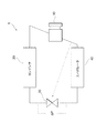
冷凍サイクル装置1は、車両用の空調装置に用いられる。図1に示すように、冷凍サイクル装置1は、コンプレッサ10、コンデンサ20、膨張弁30、およびエバポレータ40を有する。これら構成部品は、配管によって環状に接続され、冷媒循環路を構成する。この冷凍サイクル装置1において、本発明の一実施形態に係る熱交換器はエバポレータ40として適用される。以下の説明では本実施形態に係る熱交換器40を「エバポレータ40」とも表記する。
[Embodiment]
The
コンプレッサ10は、車両の走行用の動力源である内燃機関またはモータ(HV(ハイブリッド車の場合)によって駆動される。圧縮機10は、エバポレータ40から冷媒を吸引し、圧縮し、コンデンサ20へ吐出する。コンプレッサ10は、圧縮機とも呼ばれる。
The
コンデンサ20は、高温冷媒を冷却する。コンデンサ20は、放熱器や凝縮器とも呼ばれる。膨張弁30は、コンデンサ20によって冷却された冷媒を減圧する。膨張弁30は、温度式膨張弁であり、エバポレータ40の出口温度に応じて弁開度が調整される。膨張弁30は、減圧器とも呼ばれ、固定の絞りや、エジェクタにも代替可能である。
The
エバポレータ40は、膨張弁30によって減圧された冷媒を蒸発させ、媒体を冷却する。エバポレータ40は、車室に供給される空気を冷却する。エバポレータ40の内部を流れる冷媒は、気液二相状態において充分な冷却機能を発揮する。このため、通常はエバポレータ40の出口近傍で冷媒が完全に気化するように膨張弁30によってエバポレータ40へ供給される冷媒の流量が制御され、これにより、エバポレータ40の全体の体積を使って媒体の冷却を行えるようにされている。
The
冷凍サイクル装置1は、さらに、高圧側液冷媒と低圧側ガス冷媒とを熱交換する内部熱交換、余剰冷媒を蓄えるレシーバまたはアキュムレータのタンク要素を備えることができる。また、動力源は、内燃機関あるいは電動機によって提供されうる。
The
図2〜10を参照して、本実施形態に係る熱交換器としてのエバポレータ40の構成を説明する。以下の説明では、図2及び図5の紙面上の上下方向(チューブ45A,45B内を流れる冷媒の流れ方向)を「高さ方向」と表し、その上側を「上側」、下側を「下側」と表す。なお、高さ方向は典型的には重力方向であるが、他の方向でもよい。また、図5の紙面上の左右方向を、チューブ45A,45Bが積層する「積層方向」と表し、その左側(冷媒入口51及び冷媒出口52が配置される側)を「手前側」と表し、右側を「奥側」と表す。そして図2に示すように、これらの高さ方向及び積層方向の両方と直交する方向を、空気が空気通路47を流れる「風流れ方向」と表し、その一方を「風上側」、他方側を「風下側」と表す。
With reference to FIGS. 2-10, the structure of the
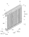
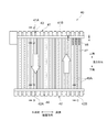
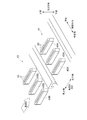
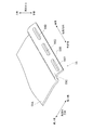
図2において、エバポレータ40は、複数に分岐した冷媒通路部材を有する。この冷媒通路部材は、アルミニウム等の金属製の通路部材によって提供される。冷媒通路部材は、組をなして位置づけられた第1ヘッダ41、第2ヘッダ42、第3ヘッダ43、第4ヘッダ44と、それらヘッダの間を連結する複数のチューブ45A,45Bとによって提供されている。第1ヘッダ41、第2ヘッダ42、第3ヘッダ43、第4ヘッダ44は、積層方向に沿って延在するよう配置されている。複数のチューブ45A,45Bは、積層方向と直交する高さ方向に沿って延在するよう配置されている。
In FIG. 2, the
図2において、第1ヘッダ41と第2ヘッダ42とは、組をなしており、互いに高さ方向に所定距離だけ離れて、積層方向に沿って平行に配置されている。第3ヘッダ43と第4ヘッダ44とも、組をなしており、互いに高さ方向に所定距離れて、積層方向に沿って平行に配置されている。第1ヘッダ41及び第3ヘッダ43は高さ方向の上側に配置され、第1ヘッダ41が風流れ方向の風下側、第3ヘッダ43が風流れ方向の風上側に配置されている。第2ヘッダ42及び第4ヘッダ44は高さ方向の下側に配置され、第2ヘッダ42が風流れ方向の風下側、第4ヘッダ44が風流れ方向の風下側に配置されている。
In FIG. 2, the
第1ヘッダ41と第2ヘッダ42との間には、複数のチューブ45Aが等間隔に積層配列されている。各チューブ45Aは、図6及び図7に示すように、その両端部において対応する第1ヘッダ41、第2ヘッダ42内に突出されることにより第1ヘッダ41及び第2ヘッダ42と連通している。これら第1ヘッダ41と、第2ヘッダ42と、それらの間に配置された複数のチューブ45Aによって、風流れ方向(空気の通過方向)に沿って通過する空気との冷媒との間で熱交換を行う風下コア48が形成されている。
Between the
第3ヘッダ43と第4ヘッダ44との間には、複数のチューブ45Bが等間隔に積層配列されている。各チューブ45Bは、その両端部において対応する第3ヘッダ43(図6参照)、第4ヘッダ44内に突出されることにより第3ヘッダ43及び第4ヘッダ44と連通している。これら第3ヘッダ43と、第4ヘッダ44と、それらの間に配置された複数のチューブ45Bによって、風流れ方向に沿って通過する空気との冷媒との間で熱交換を行う風上コア49が形成されている。
A plurality of
この結果、エバポレータ40は、2層に配置された風下コア48と風上コア49とを有する。風流れ方向に関して、風上コア49が風上側に配置され、風下コア48が風下側に配置されている。また、図3に示すように、複数のチューブ45A,45Bは、風流れ方向に沿って一対となるように、チューブの積層方向に沿って2列に配置されている。
As a result, the
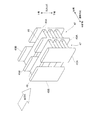
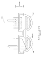
第1ヘッダ41の端部(積層方向手前側の端部)には、冷媒入口51としてのコネクタが設けられている。図4及び図5に示すように、第1ヘッダ41内は、その長さ方向(積層方向)のほぼ中央において、第1区画の分配タンク41Aと、第2区画の集合タンク41Bとに区画されて、相互間を封止されている。また、第2ヘッダ42内は、その長さ方向(積層方向)のほぼ中央において、第1区画の集合タンク42Aと、第2区画の分配タンク42Bとに区画されて、相互間を連通されている。これに対応して、複数のチューブ45Aは、第1区画に対応した第1群G1と、第2区画に対応した第2群G2とに区分されている。
A connector as a
冷媒は、冷媒入口51から第1ヘッダ41の分配タンク41Aに供給される。冷媒は、分配タンク41Aから、第1群G1に属する複数のチューブ45Aに分配される。冷媒は、第1群G1を通して第2ヘッダ42の集合タンク42Aに流入し、集合される。冷媒は、第2ヘッダ42内で集合タンク42Aから分配タンク42Bに流入し、分配タンク42Bから、第2群G2に属する複数のチューブ45Aに再び分配される。冷媒は、第2群G2を通して第1ヘッダ41の集合タンク41Bに流入し、集合される。このように、風下コア48においては、冷媒をU字状に流す流路が形成される。
The refrigerant is supplied from the
第3ヘッダ43の端部(流入方向手前側の端部)には、冷媒出口52としてのコネクタが設けられている。図4に示すように、第3ヘッダ43内は、その長さ方向のほぼ中央において、第1区画の分配タンク43Aと、第2区画の集合タンク43Bとに区画されて、相互間を封止されている。第3ヘッダ43の分配タンク43Aは、第1ヘッダ41の集合タンク41Bに隣接している。第3ヘッダ43の分配タンク43Aと、第1ヘッダ41の集合タンク41Bとは連通している。また、第4ヘッダ44内は、その長さ方向(積層方向)のほぼ中央において、第1区画の集合タンク44Aと、第2区画の分配タンク44Bとに区画されて、相互間を連通されている。これに対応して、複数のチューブ45Bは、第1区画に対応した第3群G3と、第2区画に対応した第4群G4とに区分されている。
A connector as a
冷媒は、第1ヘッダ41の集合タンク41Bからから、第3ヘッダ43の分配タンク43Aに流入する。冷媒は、分配タンク43Aから、第3群G3に属する複数のチューブ45Bに分配される。冷媒は、第3群G3を通して第4ヘッダ44の集合タンク44Aに流入し、集合される。冷媒は、第4ヘッダ44内で集合タンク44Aから分配タンク44Bに流入し、分配タンク44Bから、第4群G4に属する複数のチューブ45Bに再び分配される。冷媒は、第4群G4を通して第3ヘッダ43の集合タンク43Bに流入し、集合される。このように、風上コア49においては、冷媒をU字状に流す流路が形成される。第3ヘッダ43の集合タンク43B内の冷媒は、冷媒出口52から流出し、コンプレッサ10へ向けて流れる。
The refrigerant flows from the collecting
本実施形態では、チューブ45A,45Bは、図6に示すように、内部に複数の冷媒通過孔50を有する多穴管である。チューブ45A,45Bは、扁平管とも呼ばれる。この多穴管は、押出製法や、板を折り曲げて形成する製法によって得ることができる。複数の冷媒通過孔50は、チューブ45A,45Bの長手方向に沿って延びており、チューブ45A,45Bの両端に開口している。1つのチューブ45A,45Bに設けられる複数の冷媒通過孔50は、風流れ方向に沿って並列に配置されている。すなわち冷媒通過孔50の配列方向は、すべて風流れ方向となる。
In the present embodiment, the tubes 45 </ b> A and 45 </ b> B are multi-hole tubes having a plurality of refrigerant passage holes 50 inside as shown in FIG. 6. The
複数のチューブ45A,45Bは、それぞれ列をなして並べられている。図3及び図6に示すように、各列において、複数のチューブ45A,45Bは、その主面が対向するように配置されている。また、図3及び図5に示すように、複数のチューブ45A,45Bは、互いに隣接する2つのチューブ45Aの間に、空気と熱交換するための空気通路47が設けられ、同様に、互いに隣接する2つのチューブ45Bの間に、空気と熱交換するための空気通路47が設けられている。
The plurality of
エバポレータ40は、車室へ供給される空気と接触面積を増加させるためのフィン部材を備える。フィン部材は、複数のコルゲート型のフィン46によって提供されている。図3及び図5に示すように、フィン46は、隣接する2つのチューブ45Aの間、及び隣接する2つのチューブ45Bの間に区画された空気通路47に配置されている。フィン46は、隣接する2つのチューブ45A,45Bと熱的に結合している。フィン46は、熱伝達に優れた接合材によって、隣接する2つのチューブ45A,45Bに接合されている。接合材としては、ろう材を用いることができる。フィン46は、薄いアルミニウム等の金属板が波状に曲げられた形状をもっており、ルーバーと呼ばれる空気通路を備える。
The
図4に模式的に示すように、冷媒入口51から第1ヘッダ41の分配タンク41Aに流れ込んだ冷媒は、第1群G1のチューブ45Aを通って第2ヘッダ42の集合タンク42Aに流れこむ(第1ターン)。第2ヘッダ42の集合タンク42Aに流れ込んだ冷媒は、第2ヘッダ42の分配タンク42Bに流れ込む。第2ヘッダ42の分配タンク42Bに流れ込んだ冷媒は、第2群G2のチューブ45Aを通って第1ヘッダ41の集合タンク41Bに流れこむ(第2ターン)。第1ヘッダ41の集合タンク41Bと第3ヘッダ43の分配タンク43Aとは連通しているので、第1ヘッダ41の集合タンク41Bに流れ込んだ冷媒は第3ヘッダ43の分配タンク43Aに流れこむ。第3ヘッダ43の分配タンク43Aに流れ込んだ冷媒は、第3群G3のチューブ45Bを通って第4ヘッダ44の集合タンク44Aに流れ込む(第3ターン)。第4ヘッダ44の集合タンク44Aに流れ込んだ冷媒は、第4ヘッダ44の分配タンク44Bに流れ込む。第4ヘッダ44の分配タンク44Bに流れ込んだ冷媒は、第4群G4のチューブ45Bを通って第3ヘッダ43の集合タンク43Bに流れこむ(第4ターン)。第3ヘッダ43の集合タンク43Bに流れ込んだ冷媒は冷媒出口52から外部に流出する。つまり、本実施形態のエバポレータ40は、所謂4ターン方式の冷媒通路を有する構成をとる。
As schematically shown in FIG. 4, the refrigerant flowing into the
なお、第1ターンを構成する分配タンク41A(第1分配タンク)、第1群G1のチューブ45A(第1チューブ群)、集合タンク42A(第1集合タンク)を纏めて「第1ユニット」とも表記する。第2ターンを構成する分配タンク42B(第2分配タンク)、第2群G2のチューブ45A(第2チューブ群)、集合タンク41B(第2集合タンク)を纏めて「第2ユニット」とも表記する。第3ターンを構成する分配タンク43A(第3分配タンク)、第3群G3のチューブ45B(第3チューブ群)、集合タンク44A(第3集合タンク)を纏めて「第3ユニット」とも表記する。第4ターンを構成する分配タンク44B(第4分配タンク)、第4群G4のチューブ45B(第4チューブ群)、集合タンク43B(第4集合タンク)を纏めて「第4ユニット」とも表記する。
Note that the
そして、特に本実施形態では、エバポレータ40は、各分配タンク41A,42B,43A,44Bのそれぞれに分配偏向部53が設けられている。分配偏向部53は、エバポレータ40に供給される冷媒が相対的に低流量のときに、各分配タンク41A,42B,43A,44Bにおいて、チューブ45A,45Bの複数の冷媒通過孔50に対し冷媒の供給量を一部に偏らせるための構成要素である。
In particular, in the present embodiment, the
分配偏向部53は、チューブ45A,45B内の冷媒の流れ方向に応じて、すなわち、(1)冷媒が高さ方向の下側から上側へ向かってチューブ内を流れる部分と、(2)冷媒が高さ方向の上側から下側へ向かってチューブ内を流れる部分とにより、異なる2種類の要素が適用される。上記(1)の部分、すなわち風下コア48の分配タンク42Bと、風上コア49の分配タンク44Bにおいては、各分配タンク内に突出するチューブの端部の形状を加工した端部加工部54が分配偏向部53として機能する。また、上記(2)の部分、すなわち風下コア48の分配タンク41Aと、風上コア49の分配タンク43Aにおいては、各分配タンクの内部に設けられる中間プレート55が分配偏向部53として機能する。
The
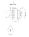
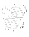
図8に示すように、端部加工部54は、上記(1)の部分、すなわち集合タンクに対して相対的に高さ方向の下側に配置される分配タンク42B,44Bにおいて、分配タンク42B,44Bの内部に突出するチューブ45A,45Bの端部に関し、複数の冷媒通過孔50の配列方向(風流れ方向)に沿って、端部の少なくとも一部の鉛直方向位置が異なるよう形成されている。具体的には、本実施形態では、端部加工部54は、チューブ45A,45Bの先端が風流れ方向に沿って斜め形状となるように形成される。この端部加工部54により、チューブ45A,45Bの内部に設けられる複数の冷媒通過孔50は、それぞれの開口の高さ方向の位置が異なるので、例えば、端部加工部54の全体が分配タンク内の冷媒の液面下に入らないような冷媒例流量時においては、液面下に開口が位置する冷媒通過孔のみに冷媒が偏って供給されることとなる。
As shown in FIG. 8, the
なお、図8は、分配タンク42B,44Bのうち分配タンク42Bにおける端部加工部54の構成を例示したものであるが、図示しない分配タンク44Bにおける端部加工部54の構成も同様のものである。また、図8の例では、端部加工部54の風下側の高さ方向位置が風上側より下方にくるように(すなわち風下側のほうが下方に突出するように)斜め形状を形成した構成を例示したが、斜め形状の向きはこの逆でもよい。
8 illustrates the configuration of the
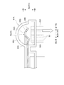
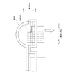
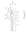
図9及び図10に示すように、中間プレート55は、上記(2)の部分、すなわち集合タンクに対して相対的に高さ方向の上側に配置される分配タンク41A,43Aにおいて、分配タンクの内部に突出するチューブ45A,45Bの端部より上方に配置され、複数のチューブ45A,45Bの積層方向に沿って延在する板状部材である。中間プレート55は、分配タンク41A,43Aの内部空間を上方部56A及び下方部56Bに区分し、かつ、風流れ方向の一部にて上方部56Aと下方部56Bとを連通する。より詳細には、図9に示すように、中間プレート55は、風上側の基部55Aにて分配タンクの内壁に接合され、風上側の自由端部55Bと内壁との間には隙間が形成されている。基部55Aと自由端部55Bとの中間には高さ方向上側へ突出した凸部55Cが形成され、これにより分配タンクの上方部56Aの基部55A側を流れる冷媒が自由端部55B側へ流出するのを抑制できるよう構成されている。また、図9及び図10に示すように、自由端部55Bの近傍には積層方向に沿って複数の連通孔55Dが設けられる。
As shown in FIGS. 9 and 10, the
分配タンク41A,43Aの上方部56Aに冷媒が流れると、まず中間プレート55の基部55A側に液溜めが作られる。この液溜めの液面が凸部55Cの高さ位置を越えると、凸部55Cを越えた冷媒のみが、連通孔55Dや、自由端部55Bと内壁との隙間を通って下方部56Bに流れる。これにより、特に中間プレート55の基部55A側の液溜めが瞬時に溢れないような冷媒低流量時において、連通孔55Dの直下やその近傍、または、自由端部55Bと内壁との隙間の直下やその近傍の冷媒通過孔のみに冷媒が偏って供給されることになる。
When the refrigerant flows to the
なお、図9は、分配タンク41A,43Aのうち分配タンク41Aにおける中間プレート55の構成を例示したものであるが、図示しない分配タンク43Aにおける中間プレート55の構成も同様のものである。また、図9の例では、中間プレート55の基部55Aが風上側、自由端部55Bや連通孔55Dが風下側に配置される構成を例示したが、中間プレート55の向きはこの逆でもよい。
9 illustrates the configuration of the
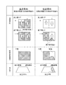
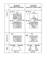
次に、本実施形態に係るエバポレータ40の効果について説明する。まず図11を参照して、従来のエバポレータ40の一般的な問題点について説明する。図11には、上記の4ターン式のエバポレータ40における(1)内部の冷媒の流れ、(2)冷媒との熱交換後の吹出空気温度(風下コア38の風下側主面に対応)、(3)吹出空気によるデフモード時の窓曇り、が模式的に図示されている。また、上記(1)〜(3)について、エバポレータ40に供給される冷媒が高流量のときの結果が図中左側に示され、低流量のときの結果が図中右側に示されている。
Next, the effect of the
図1に示したような冷凍サイクル装置1において、エバポレータ40は、車室に供給される空気を冷却するために機能する。通常は、エバポレータ40による空気の冷却性能をエバポレータ40のコア部全体に亘って充分に確保すべく、エバポレータ40の出口近傍で冷媒が完全に気化され、その他の大半の部分では冷媒の気液二相状態が維持されるように、エバポレータ40へ供給される冷媒の流量は膨張弁30によって制御される。より詳細には、図1に示すように、エバポレータ40の出口温度をセンシングして膨張弁30の制御系へフィードバックし、この出口温度に基づいて膨張弁30の弁開度を調整することにより、エバポレータ40の全体の体積を使って空気の冷却を行えるように冷媒の流量を制御する。
In the
図11に示す冷媒の「高流量時」とは、このように膨張弁30の弁開度の調整によって充分に冷媒の流量制御が可能な状態を意味する。このとき、図11の左側部分に示すように、エバポレータ40の内部を流れる冷媒は、風上コア49の冷媒出口近傍のみで完全に気化された状態となり、それ以外の部分(第1〜第3ターンの全域、及び第4ターンの出口近傍以外の領域)では気液二相状態である。冷媒が気液二相状態となる部分は、空気を冷却するために充分に低温の領域であり、高流量時には風下コア48の全域と、風上コア49の大半において低温となっている。したがって、このような良好な状態のエバポレータ40を通過した空気はコア全域に亘って充分に冷却され、全体が冷風となっており、吹き出し空気の温度分布はコア全域に亘り均一になっている。この結果、ムラのない冷風が吹き付けられた窓にも窓曇りは発生しない。
The “high flow rate” of the refrigerant shown in FIG. 11 means a state in which the flow rate of the refrigerant can be sufficiently controlled by adjusting the valve opening degree of the
ところで、例えば外気温度が低くなったときなど、膨張弁30の上流側と下流側との差圧ΔPが小さくなりすぎると、膨張弁30の弁開度調整では冷媒に充分な流速を付けることができず冷媒が流れにくくなる状況が起こり得る。図11に示す冷媒の「低流量時」とは、このように膨張弁30の弁開度の調整では、エバポレータ40に供給する冷媒の流量制御を適切に行うことができない状態を意味する。このとき、図11の右側部分に示すように、エバポレータ40の内部を流れる冷媒は、充分な流量で供給されず流速が遅いため風下コア48の第2ターンの途中で蒸発が完了してしまい、それ以降の領域(図11では、第2ターンの一部、第3〜第4ターンの全域)では完全に気化された状態となってしまう。このため低流量時には、風下コア48の約半分程度しか低温とならず、この部分しか熱交換器として働かない状態となっている。したがって、このように冷却性能が悪化した状態のエバポレータ40を通過した空気は、コアの一部分の領域しか冷風にできないため、気液二相状態の冷媒と熱交換ができない部分は充分に冷却できず暖風となる。このため、吹き出し空気の温度分布はコア全体で均一とはならないムラのあるものとなっている。この結果、ムラのある吹出し空気が吹き付けられる窓において、暖風が吹き付けられた部分には窓曇りが発生する。
By the way, when the differential pressure ΔP between the upstream side and the downstream side of the
以上より、エバポレータ40に対し、冷媒が比較的低流量においても各冷媒通路に均等に冷媒を流し、エバポレータ40を通過した後の吹き出し空気の空気温度分布を均一に保つことが望ましい。
As described above, it is desirable that the refrigerant is caused to flow evenly through the refrigerant passages even when the flow rate of the refrigerant is relatively low, and the air temperature distribution of the blown air after passing through the
このようなニーズを満たすべく、本実施形態のエバポレータ40では、4ターン方式の各ターンの分配タンク41A,42B,43A,44Bにおいて、冷媒が相対的に低流量のとき複数の冷媒通過孔50に対し冷媒の供給量を一部に偏らせる分配偏向部53が設けられている。
In order to satisfy such needs, in the
この構成により、冷媒の低流量時に、同一の分配タンク内に開口する複数のチューブのそれぞれに設けられる複数の冷媒通過孔50のすべてに液冷媒を充分な流量で供給できない状況であっても、分配偏向部53によって同一チューブの複数の冷媒通過孔50のうちの一部に集中して液冷媒が供給されるようになる。これにより、複数の冷媒通過孔50に供給されるはずだった液冷媒を少数の冷媒通過孔に集約して供給されるので、冷媒通過孔50の1つ当たりに供給される冷媒の流量を増加させることができる。これにより、液冷媒の流速が増加し、冷媒通路の途中での冷媒の蒸発が抑制され、より後流側(冷媒出口52の側)まで冷媒の気液二相状態を維持させることができる。したがって、冷媒の低流量時でも、エバポレータ40のコア部の全体において好適に低温状態を維持させることができ、冷媒との熱交換後の空気の温度分布の均一化を図ることができる。この結果、冷媒が相対的に低流量の場合においても、冷媒との熱交換後の空気の温度分布を均一に保つことができる。
With this configuration, even when the refrigerant is at a low flow rate, even when the liquid refrigerant cannot be supplied at a sufficient flow rate to all of the plurality of refrigerant passage holes 50 provided in each of the plurality of tubes opened in the same distribution tank, The
また、本実施形態のエバポレータ40において、分配偏向部53は、冷媒を上方に向けて供給する分配タンク42B及び分配タンク44Bにおいて、分配タンクの内部に突出するチューブの端部に関し、複数の冷媒通過孔50の配列方向(風流れ方向)に沿って端部の少なくとも一部の鉛直方向位置が異なるよう形成された端部加工部54を含む。より詳細には、端部加工部54は、複数の冷媒通過孔の配列方向(風流れ方向)に対して、分配タンクの内部に突出するチューブの端部が傾斜状に形成される。
Further, in the
この構成により、高さ方向の下側に配置される分配タンク42B及び分配タンク44Bにおいて、冷媒の低流量時には、図8に示すようにタンク内の冷媒が気液分離されるのに伴い、傾斜状に形成される端部加工部54のうち液面下に入る部分が少なくなる。つまり、単一のチューブの複数の冷媒通過孔のうち液冷媒が供給される冷媒通過孔の数を、冷媒の流量が少なくなるにつれて減少させることができる。このように、高さ方向の下側に配置される分配タンク42B及び分配タンク44Bに分配偏向部53として端部加工部54を適用することによって、これらの分配タンク42B,44Bから上方に向けて冷媒を流すチューブ45A,45Bにおいて、冷媒の流量低下に応じて、同一チューブの複数の冷媒通過孔50のうちの一部に偏らせて液冷媒を供給することが可能となる。また、端部加工部54は、チューブ45A,45Bの端部を斜め形状に加工するだけで作成できるので、冷媒の低流量時に複数の冷媒通過孔50に対し液冷媒の供給量を一部に偏らせるという分配偏向部53の機能を簡易に実施することができる。なお、端部加工部54の斜め形状は、風下側が風上側に対して下方になるように形成されるのが好ましい。これにより、風下側の冷媒通過孔50に液冷媒を集約できるので、空気の冷却効果を向上できる。
With this configuration, in the
また、本実施形態のエバポレータ40において、分配偏向部53は、冷媒を下方に向けて供給する分配タンク41A及び分配タンク43Aにおいて、分配タンクの内部に突出するチューブ45A,45Bの端部より上方に配置され、複数のチューブ45A,45Bの積層方向に沿って延在して分配タンク41A,43Aの内部空間を上方部56A及び下方部56Bに区分し、かつ、複数の冷媒通過孔50の配列方向の一部にて上方部56Aと下方部56Bとを連通する中間プレート55を含む。
Further, in the
この構成により、高さ方向の上側に配置される分配タンク41A及び分配タンク43Aにおいて、冷媒の低流量時には、図9に示すようにタンク内の上方部56Aに導入された液冷媒は中間プレート55の基部55A側に貯留されて、基部55Aの直下にある風流れ方向風上側の冷媒通過孔50には液冷媒が供給されにくくなる。一方、中間プレート55の自由端部55B側では、連通孔55Dや、自由端部55Bと内壁との隙間を通って、これらの連通孔55Dや隙間の直下にある風流れ方向風下側の一部の冷媒通過孔50のみに集中的に液冷媒が供給されるようになる。このように、高さ方向の上側に配置される分配タンク41A,43Aに分配偏向部53として中間プレート55を設けることによって、これらの分配タンク41A,43Aから下方に向けて冷媒を流すチューブ45A,45Bにおいて、冷媒の流量低下に応じて、同一チューブの複数の冷媒通過孔50のうちの一部に偏らせて液冷媒を供給することが可能となる。なお、中間プレート55は、基部55Aに対して自由端部55Bが風流れ方向の風下側に位置するように設けられるのが好ましい。これにより、風下側の冷媒通過孔50に液冷媒を集約できるので、空気の冷却効果を向上できる。
With this configuration, in the
[第1変形例]
図12〜図15を参照して上記実施形態の第1変形例について説明する。第1変形例は、上記実施形態に示す4ターン式のエバポレータ40において、分配タンク41A,42B,43A,44Bに設けられる分配偏向部53の構成変更に関するものである。
[First Modification]
A first modification of the above embodiment will be described with reference to FIGS. The first modification relates to a configuration change of the
上記実施形態では、集合タンク41B,43Bに対して相対的に高さ方向の下側に配置される分配タンク42B,44Bに、分配偏向部53として端部加工部54を設ける構成を例示した。端部加工部54は、上記実施形態では図8に示すように、風流れ方向に対して傾斜状に形成されたものであったが、風流れ方向に沿って端部の少なくとも一部の鉛直方向位置が異なるよう形成され、分配偏向部53としての機能を発揮できれば他の形状でもよい。例えば、図12に示すように、複数の冷媒通過孔50の配列方向(風流れ方向)に沿って、分配タンク42B,44Bの内部に突出するチューブ45A,45Bの端部の一部が他の部分に対して下方に突出するよう形成される端部加工部154を適用することもできる。
In the above-described embodiment, the configuration in which the
この構成により、高さ方向の下側に配置される分配タンク42B及び分配タンク44Bにおいて、冷媒の低流量時には、図12に示すようにタンク内の冷媒が気液分離されるのに伴い、端部加工部154のうち液面下に入る部分は下方に突出する一部のみとなる。つまり、上記の端部加工部54と同様に、これらの分配タンク42B,44Bから上方に向けて冷媒を流すチューブ45A,45Bにおいて、冷媒の流量低下に応じて、同一チューブの複数の冷媒通過孔50のうちの一部に偏らせて液冷媒を供給することが可能となる。
With this configuration, in the
なお、端部加工部154における突出部の位置は、図12に示すように最も風下側の位置とすることが好ましいが、これより風上側の位置とすることもできる。
In addition, although the position of the protrusion part in the edge
また、上記実施形態では、集合タンク42A,44Aに対して相対的に高さ方向の上側に配置される分配タンク41A,43Aに、分配偏向部53として中間プレート55を設ける構成を例示したが、この代わりに、分配タンク41A,43Aの内部に突出するチューブ45A,45Bの端部に関し、複数の冷媒通過孔50の配列方向(風流れ方向)に沿って端部の少なくとも一部の鉛直方向位置が異なるよう形成された端部加工部を備える構成としてもよい。例えば図13に示すように、複数の冷媒通過孔50の配列方向に対して、分配タンク41A,43Aの内部に突出するチューブ45A,45Bの端部が傾斜状に形成される端部加工部155を備える構成とすることができる。
Further, in the above-described embodiment, the configuration in which the
この構成により、高さ方向の上側に配置される分配タンク41A,43Aにおいて、冷媒の低流量時には、図13に示すようにタンク内の冷媒が気液分離されるのに伴い、傾斜状に形成される端部加工部155のうち液面下に入る部分が少なくなる。つまり、上記の端部加工部54と同様に、単一のチューブの複数の冷媒通過孔のうち液冷媒が供給される冷媒通過孔の数を、冷媒の流量が少なくなるにつれて減少させることができる。したがって、上記の中間プレート55を設ける構成と同様に、高さ方向の上側に配置される分配タンク41A,43Aにおいても分配偏向部53として端部加工部155を適用することによって、これらの分配タンク41A,43Aから下方に向けて冷媒を流すチューブ45A,45Bにおいて、冷媒の流量低下に応じて、同一チューブの複数の冷媒通過孔50のうちの一部に偏らせて液冷媒を供給することが可能となる。なお、端部加工部155の斜め形状は、図13に示すように、風下側が風上側に対して下方になるように(すなわち風上側のほうが上方に突出するように)形成され、風下側の冷媒通過孔50に液冷媒を集約できるのが好ましいが、斜め形状の向きはこの逆でもよい。
With this configuration, in the
また、上側の分配タンク41A,43Aに端部加工部を適用する場合、図13に示す例の他にも、例えば図14に示すように、複数の冷媒通過孔50の配列方向(風流れ方向)に沿って、分配タンク41A,43Aの内部に突出するチューブ45A,45Bの端部の一部が他の部分に対して下方に凹むよう形成される端部加工部156を備える構成とすることもできる。
In addition, in the case of applying the end processing portion to the
この構成により、高さ方向の上側に配置される分配タンク41A,43Aにおいて、冷媒の低流量時には、図14に示すようにタンク内の冷媒が気液分離されるのに伴い、端部加工部156のうち液面下に入る部分は下方に凹む一部のみとなる。つまり、上記の端部加工部155と同様に、これらの分配タンク41A,43Aから下方に向けて冷媒を流すチューブ45A,45Bにおいて、冷媒の流量低下に応じて、同一チューブの複数の冷媒通過孔50のうちの一部に偏らせて液冷媒を供給することが可能となる。
With this configuration, in the
なお、端部加工部156において端部を凹ませる部分の位置は、図14に示すように最も風下側の位置とすることが好ましいが、これより風上側の位置とすることもできる。
In addition, although the position of the part which dents an edge part in the edge
また、上記実施形態では、集合タンク42A,44Aに対して相対的に高さ方向の上側に配置される分配タンク41A,43Aに、分配偏向部53として中間プレート55を設ける構成を例示したが、中間プレート55の形状はこれに限られない。例えば図15に示すように、他の形状の中間プレート157を設ける構成としてもよい。
Further, in the above-described embodiment, the configuration in which the
中間プレート157は、風流れ方向の風上側だけでなく風下側も分配タンク41A,43Aの内壁に接続されている点が上記実施形態の中間プレート55と異なる。中間プレート157は、上記実施形態の中間プレート55と同様に、分配タンク41A,43Aの内部空間を上方部56A及び下方部56Bに区分する。中間プレート157は、風流れ方向の略中央部分にて高さ方向の上側に向かって凸形状となる凸部157Aを備え、分配タンクの上方部56Aに冷媒が流れると、まず中間プレート157の凸部157Aの風流れ方向の両側に液溜めが作られるよう構成されている。中間プレート157の液溜めが作られる任意の部分には、積層方向に沿って複数の連通孔157Bが設けられ、この連通孔157Bのみを介して上方部56A側の液冷媒を下方部56B側に供給できるよう構成されている。
The
この構成により、高さ方向の上側に配置される分配タンク41A及び分配タンク43Aにおいて、冷媒の低流量時には、図15に示すようにタンク内の上方部56Aに導入された液冷媒は、連通孔157Bを通って、これらの連通孔157Bの直下にある一部の冷媒通過孔50のみに集中的に供給されるようになる。このように、高さ方向の上側に配置される分配タンク41A,43Aに分配偏向部53として中間プレート157を設けることによって、これらの分配タンク41A,43Aから下方に向けて冷媒を流すチューブ45A,45Bにおいて、冷媒の流量低下に応じて、同一チューブの複数の冷媒通過孔50のうちの一部に偏らせて液冷媒を供給することが可能となる。
With this configuration, in the
また、上記実施形態では、4ターン式のエバポレータ40において、すべての分配タンク41A,42B,43A,44Bに分配偏向部53を設ける構成を例示したが、これに限られない。
Further, in the above-described embodiment, the configuration in which the
分配偏向部53は、少なくとも、風下コア48の分配タンク41A及び分配タンク42Bのうちの冷媒入口51から遠い側のみに設けられればよい。本実施形態のように、冷媒入口51が高さ方向上側の分配タンク41Aに設けられる4ターン式の構成の場合には、高さ方向下側に配置される分配タンク42Bが該当する。この場合には、分配タンク42Bに、図8または図12に示した端部加工部54,154を適用することができる。
The
図11を参照して説明したように、従来の4ターン式エバポレータの場合、冷媒の低流量時に液冷媒が完全に気化するのは、風下コア48のうち冷媒入口51から遠い第2ターンの場合が多い。このため、第2ターンのチューブ45Aに冷媒を導入する分配タンク42Bにおいて分配偏向部53を設けて、冷媒を供給する冷媒通過孔50の数を絞って冷媒流量を増やすことにより、第2ターンにおける液冷媒の気化を好適に防ぐことができ、冷媒の低流量時でも、エバポレータ40のコア部の全体において好適に低温状態を維持させることができる。
As described with reference to FIG. 11, in the case of the conventional four-turn evaporator, the liquid refrigerant is completely vaporized at the low flow rate of the refrigerant in the second turn far from the
また、分配偏向部53は、風下コア48の分配タンク41A及び分配タンク42Bの両方に設け、風上コア49に設けない構成とすることもできる。この場合には、分配タンク42Bに、図8または図12に示した端部加工部54,154を適用することができ、分配タンク41Aには、図9、図13〜図15に示した中間プレート55、端部加工部155,156,中間プレート157を適用することができる。これにより、風下コア48の全体に亘って冷媒を供給する冷媒通過孔の数を絞って冷媒流量を増やすことができ、冷媒の低流量時でも、エバポレータ40の風下コア48の全体において好適に低温状態を維持させることができる。
Further, the
言い換えると、分配偏向部53は、少なくとも風下コア48の分配タンク41A,42Bのみに設けられる構成であればよい。風下コア48に分配偏向部53を設けることで、風下コア48の各チューブ45Aにおける冷媒温度差を低減できる。空気がエバポレータ40を通過する際の出口側の風下コア48において冷媒の温度差を低減させることで、最終的にチューブ45A、45Bとの熱交換を終えて出力される空気の温度分布をより効果的に均一に保つことができる。
In other words, the
また、分配偏向部53は、風下コア48の分配タンク41A及び分配タンク42Bに加えて、さらに風上コア49の分配タンク43A及び分配タンク44Bのうち冷媒出口に近い側のみに設けることもできる。本実施形態のように、冷媒出口52が高さ方向上側の集合タンク43Bに設けられる4ターン式の構成の場合には、高さ方向上側に配置される分配タンク43Aが該当する。この場合には、分配タンク43Aに、図9、図13〜図15に示した中間プレート55、端部加工部155,156,中間プレート157を適用することができる。
In addition to the
図11を参照して説明したように、従来の4ターン式エバポレータの場合、風上コア49では冷媒出口52に近い側の第4ターンのほうが、チューブ45B内で液冷媒が完全に気化して温度差が生じやすい。このため、第4ターンのチューブ45Bに冷媒を導入する分配タンク44Bにおいて分配偏向部53を設けて、冷媒を供給する冷媒通過孔50の数を絞って冷媒流量を増やすことにより、第4ターンにおける液冷媒の気化を好適に防ぐことができ、冷媒の低流量時でも、風下コア48に加えて風上コア49でも好適に低温状態を維持させることができる。
As described with reference to FIG. 11, in the case of the conventional 4-turn evaporator, in the
また、分配偏向部53は、風下コア48の分配タンク41A及び分配タンク42Bに加えて、風上コアの分配タンク43A及び分配タンク44Bの両方に設けることもできる。この場合には、分配タンク44Bには、図8または図12に示した端部加工部54,154を適用することができ、分配タンク43Aには、図9、図13〜図15に示した中間プレート55、端部加工部155,156,中間プレート157を適用することができる。これにより、風上コア49の全体に亘って冷媒を供給する冷媒通過孔の数を絞って冷媒流量を増やすことができ、冷媒の低流量時でも、エバポレータ40の風上コア49の全体において好適に低温状態を維持させることができる。
In addition to the
以上より、冷媒入口51及び冷媒出口52が高さ方向上側の分配タンク41A及び集合タンク43Bにそれぞれ設けられる4ターン式の構成のエバポレータ40の場合には、分配偏向部53を設置する優先順位は、分配タンク42B、分配タンク41A、分配タンク44B、分配タンク43Aの順番となる。
From the above, in the case of the
なお、上記実施形態のエバポレータ40とは反対に、冷媒入口51及び冷媒出口52が高さ方向下側のタンクに設けられる4ターン式の構成のエバポレータの場合においても、分配偏向部53を設置する優先順位は同様である。すなわち、優先順位の一位は、風下コア48の冷媒入口51から遠い側の分配タンク(実施形態とは逆に冷媒を下方に向けて供給する分配タンク)であり、二位は、風下コア48の冷媒入口51側の分配タンク(実施形態とは逆に冷媒を上方に向けて供給する分配タンク)であり、三位は、風上コア49の冷媒出口52側の分配タンク(実施形態とは逆に冷媒を下方に向けて供給する分配タンク)であり、四位は、風上コア49の冷媒出口52から遠い側の分配タンク(実施形態とは逆に冷媒を上方に向けて供給する分配タンク)である。この場合、各ターンの分配タンクの上下位置が入れ替わるため、各ターンの分配タンクに分配偏向部53として適用する形態も入れ替わる。すなわち、上記の一位と三位の分配タンクには、実施形態の分配タンク41A,43Aと同様に、図9、図13〜図15に示した中間プレート55、端部加工部155,156,中間プレート157を適用することができる。また、上記の二位と四位の分配タンクには、実施形態の分配タンク42B,44Bと同様に、図8または図12に示した端部加工部54,154を適用することができる。
Contrary to the
[第2変形例]
図16〜図18を参照して上記実施形態の第2変形例について説明する。第2変形例は、上記実施形態に示す4ターン式のエバポレータ40に適用した分配偏向部53を、2ターン式のエバポレータ140に適用する構成変更に関するものである。
[Second Modification]
A second modification of the above embodiment will be described with reference to FIGS. The second modification relates to a configuration change in which the
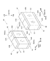
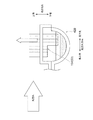
例えば図16に示すように、第1ヘッダ141、第2ヘッダ142、第3ヘッダ143、第4ヘッダ144内部の区画を無くすような構成にすることができる。図16に示されるエバポレータ140では、第1ヘッダ141に流れ込んだ冷媒は、風下コア48のチューブ45Aを通って第2ヘッダ142に流れ込む(第1ターン)。第2ヘッダ142と第4ヘッダ144とは連通しているので、第2ヘッダ142に流れ込んだ冷媒は第4ヘッダ144に流れ込む。第4ヘッダ144に流れ込んだ冷媒は、風上コア49のチューブ45Bを通って第3ヘッダ143に流れこむ(第2ターン)。第3ヘッダ143に流れ込んだ冷媒は外部に流出する。つまり、エバポレータ140は、所謂2ターン方式の冷媒通路を有する構成をとる。
For example, as shown in FIG. 16, the
つまり、2ターン方式のエバポレータ140の場合、第1ヘッダ141が、下方へ冷媒を流すチューブ45Aに冷媒を供給する分配タンクとして機能し、第2ヘッダ142がこのチューブ45Aを流れた冷媒を集約する集合タンクとして機能する。また、第4ヘッダ144が、上方へ冷媒を流すチューブ45Bに冷媒を供給する分配タンクとして機能し、第3ヘッダ143がこのチューブ45Bを流れた冷媒を集約する集合タンクとして機能する。
That is, in the case of the two-
なお、2ターン方式のエバポレータ140において、風下コア48(第1ターン)の分配タンク141、チューブ45A、集合タンク142をそれぞれ「第1分配タンク」「第1チューブ群」「第1集合タンク」とも表記する。風上コア49(第2ターン)の分配タンク144、チューブ45B、集合タンク143をそれぞれ「第2分配タンク」「第2チューブ群」「第2集合タンク」とも表記する。
In the two-
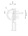
図17は、図5のB−B断面、またはC−C断面に相当する。図17に示すように、エバポレータ140では、上方に向けて冷媒をチューブに供給する分配タンク144に、分配偏向部53として端部加工部158が設けられている。なお、端部加工部158の代わりに、図12に示した端部加工部154を適用することもできる。
FIG. 17 corresponds to the BB cross section or the CC cross section of FIG. As shown in FIG. 17, in the
また、エバポレータ140では、下方に向けて冷媒をチューブに供給する分配タンク141に、分配偏向部53として図9、図13〜図15に示した中間プレート55、端部加工部155,156,中間プレート157のいずれかが設けられる。上記実施形態と同様の構成であるため図示は省略する。
Further, in the
図18は、2ターン方式の従来のエバポレータによる冷媒特性の一例を示す図である。図18の各図の内容は、図11の4ターン方式のものに対応している。 FIG. 18 is a diagram showing an example of refrigerant characteristics of a conventional evaporator of a two-turn system. 18 corresponds to the four-turn system of FIG.
図18の左側部分に示すように、冷媒が高流量時においては、エバポレータ140の内部を流れる冷媒は、風上コア49の冷媒出口近傍のみで完全に気化され、それ以外の部分(風下コア48の全域、風上コア49の出口近傍以外の領域)では気液二相状態である。冷媒が気液二相状態となる部分は、空気を冷却するために充分に低温の領域であり、高流量時には風下コア48の全域と、風上コア49の大半において低温となっている。したがって、このような良好な状態のエバポレータ140を通過した空気はコア全域に亘って充分に冷却され、全体が冷風となっており、吹き出し空気の温度分布はコア全域に亘り均一になっている。この結果、ムラのない冷風が吹き付けられた窓にも窓曇りは発生しない。
As shown in the left part of FIG. 18, when the refrigerant is at a high flow rate, the refrigerant flowing inside the
一方、図18の右側部分に示すように、冷媒が低流量時においては、エバポレータ140の内部を流れる冷媒は、充分な流量で供給されないため風下コア48の途中で蒸発が始まり、風上コア49の入口近傍で蒸発が完了してしまい、それ以降の領域(風上コア49の大半)では完全に気化された状態となってしまう。このため低流量時には、風下コア48における冷媒が気液二相状態となる部分しか熱交換器として働かない状態となっている。したがって、このように冷却性能が悪化した状態のエバポレータ140を通過した空気は、コアの一部分の領域しか冷風にできないため、気液二相状態の冷媒と熱交換ができない部分は充分に冷却できず暖風となる。このため、吹き出し空気の温度分布はコア全体で均一とはならないムラのあるものとなっている。この結果、ムラのある吹出し空気が吹き付けられる窓において、暖風が吹き付けられた部分には窓曇りが発生する。
On the other hand, as shown in the right part of FIG. 18, when the refrigerant is at a low flow rate, the refrigerant flowing inside the
以上より、エバポレータ140に対し、冷媒が比較的低流量においても各冷媒通路に均等に冷媒を流し、エバポレータ140を通過した後の吹き出し空気の空気温度分布を均一に保つことが望ましい。このような2ターン式のエバポレータ140の問題は、図11を参照して説明した4ターン式のエバポレータ40の問題と同様である。したがって、2ターン式のエバポレータ140においても、上記実施形態と同様に、風下コア48の分配タンク141及び風上コア49の分配タンク144において、冷媒が相対的に低流量のとき複数の冷媒通過孔50に対し冷媒の供給量を一部に偏らせる分配偏向部53を設け、上記実施形態と同様の機能を発揮させることにより、4ターン式と同様の効果を奏することができる。
As described above, it is desirable that the refrigerant flows evenly through the refrigerant passages even when the refrigerant is at a relatively low flow rate, and the air temperature distribution of the blown air after passing through the
なお、分配偏向部53は、少なくとも、風下コア48の分配タンク141のみに設けられ、風上コア49の分配タンク144に設けない構成とすることもできる。これにより、風下コア48の全体に亘って冷媒を供給する冷媒通過孔の数を絞って冷媒流量を増やすことができ、冷媒の低流量時でも、エバポレータ140の風下コア48の全体において好適に低温状態を維持させることができる。風下コア48に分配偏向部53を設けることで、空気がエバポレータ40を通過する際の出口側の風下コア48において冷媒の温度差を低減させることで、最終的にチューブ45A、45Bとの熱交換を終えて出力される空気の温度分布をより効果的に均一に保つことができる。つまり、冷媒入口51及び冷媒出口52が高さ方向上側の分配タンク141及び集合タンク143にそれぞれ設けられる2ターン式の構成のエバポレータ140の場合には、分配偏向部53を設置する優先順位は、(1)冷媒を下方に向けて供給する風下コア48の分配タンク141、(2)冷媒を上方に向けて供給する風上コア49の分配タンク144、の順番となる。
The
なお、上記実施形態のエバポレータ140とは反対に、冷媒入口51及び冷媒出口52が高さ方向下側のタンクに設けられる2ターン式の構成のエバポレータの場合においても、分配偏向部53を設置する優先順位は同様である。すなわち、優先順位の一位は、風下コア48の分配タンク(図16とは逆に冷媒を上方に向けて供給する分配タンク)であり、二位は、風上コア49の分配タンク(図16とは実施形態とは逆に冷媒を下方に向けて供給する分配タンク)である。この場合、各ターンの分配タンクの上下位置が入れ替わるため、各ターンの分配タンクに分配偏向部53として適用する形態も入れ替わる。すなわち、上記の一位の分配タンクには、上記(2)の分配タンク144と同様に、図8または図12に示した端部加工部54,154を適用することができる。また、上記の二位の分配タンクには、上記(1)の分配タンク141と同様に、図9、図13〜図15に示した中間プレート55、端部加工部155,156,中間プレート157を適用することができる。
In contrast to the
なお、このような冷媒入口51及び冷媒出口52が高さ方向下側のタンクに設けられる2ターン式の構成のエバポレータにおいて、風下コア48(第1ターン)の分配タンク、チューブ45A、集合タンクをそれぞれ「第3分配タンク」「第3チューブ群」「第3集合タンク」とも表記する。風上コア49(第2ターン)の分配タンク、チューブ45B、集合タンクをそれぞれ「第4分配タンク」「第4チューブ群」「第4集合タンク」とも表記する。
In the evaporator having the two-turn configuration in which the
以上、具体例を参照しつつ本発明の実施の形態について説明した。しかし、本発明はこれらの具体例に限定されるものではない。すなわち、これら具体例に、当業者が適宜設計変更を加えたものも、本発明の特徴を備えている限り、本発明の範囲に包含される。例えば、前述した各具体例が備える各要素及びその配置、材料、条件、形状、サイズなどは、例示したものに限定されるわけではなく適宜変更することができる。また、前述した各実施の形態が備える各要素は、技術的に可能な限りにおいて組み合わせることができ、これらを組み合わせたものも本発明の特徴を含む限り本発明の範囲に包含される。 The embodiments of the present invention have been described above with reference to specific examples. However, the present invention is not limited to these specific examples. In other words, those specific examples that have been appropriately modified by those skilled in the art are also included in the scope of the present invention as long as they have the characteristics of the present invention. For example, the elements included in each of the specific examples described above and their arrangement, materials, conditions, shapes, sizes, and the like are not limited to those illustrated, and can be changed as appropriate. Moreover, each element with which each embodiment mentioned above is provided can be combined as long as technically possible, and the combination of these is also included in the scope of the present invention as long as it includes the features of the present invention.
40,140:エバポレータ(熱交換器)
41A:分配タンク(第1分配タンク)
41B:集合タンク(第2集合タンク)
42A:集合タンク(第1集合タンク)
42B:分配タンク(第2分配タンク)
43A:分配タンク(第3分配タンク)
43B:集合タンク(第4集合タンク)
44A:集合タンク(第3集合タンク)
44B:分配タンク(第4分配タンク)
45A,45B:チューブ
48:風下コア
49:風上コア
50:冷媒通過孔
51:冷媒入口
52:冷媒出口
53:分配偏向部
54,154,155,156:端部加工部(分配偏向部)
56A:上方部
56B:下方部
57,157:中間プレート(分配偏向部)
141:分配タンク(第1分配タンク)
142:集合タンク(第1集合タンク)
143:集合タンク(第2集合タンク)
144:分配タンク(第2分配タンク)
40,140: Evaporator (heat exchanger)
41A: Distribution tank (first distribution tank)
41B: Collective tank (second collective tank)
42A: Collective tank (first collective tank)
42B: Distribution tank (second distribution tank)
43A: Distribution tank (third distribution tank)
43B: Collective tank (fourth collective tank)
44A: Collective tank (third collective tank)
44B: Distribution tank (fourth distribution tank)
45A, 45B: Tube 48: Downwind core 49: Upwind core 50: Refrigerant passage hole 51: Refrigerant inlet 52: Refrigerant outlet 53:
56A:
141: Distribution tank (first distribution tank)
142: Collective tank (first collective tank)
143: Collective tank (second collective tank)
144: Distribution tank (second distribution tank)
Claims (22)
前記複数のチューブのそれぞれの内部に設けられ、内部に冷媒を流す複数の冷媒通過孔(50)であって、前記冷媒の流れ方向及び前記複数のチューブの積層方向と直交する方向に沿って並列に配置される複数の冷媒通過孔と、
前記冷媒の流れの上流側にて前記複数のチューブと接続され、供給された前記冷媒を前記複数のチューブに分配する分配タンク(41A,42B,43A,44B)と、
前記冷媒の流れの下流側にて前記複数のチューブと接続され、前記複数のチューブを流れた前記冷媒を集合させる集合タンク(42A,41B,44A,43B)と、
前記分配タンクに設けられ、前記冷媒が相対的に低流量のとき前記複数の冷媒通過孔に対し前記冷媒の供給量を一部に偏らせる分配偏向部(53)と、
を備える熱交換器(40,140)。 A plurality of stacked tubes (45A, 45B);
A plurality of refrigerant passage holes (50) that are provided inside each of the plurality of tubes and allow a refrigerant to flow therein, and are arranged in parallel along a direction orthogonal to the flow direction of the refrigerant and the stacking direction of the plurality of tubes. A plurality of refrigerant passage holes arranged in
A distribution tank (41A, 42B, 43A, 44B) that is connected to the plurality of tubes on the upstream side of the flow of the refrigerant and distributes the supplied refrigerant to the plurality of tubes;
A collecting tank (42A, 41B, 44A, 43B) that is connected to the plurality of tubes on the downstream side of the flow of the refrigerant and collects the refrigerant that has flowed through the plurality of tubes;
A distribution deflecting portion (53) provided in the distribution tank and biasing the supply amount of the refrigerant in part with respect to the plurality of refrigerant passage holes when the refrigerant has a relatively low flow rate;
A heat exchanger (40, 140) comprising:
前記空気の通過方向の風下側に設けられ、前記冷媒を導入する冷媒入口(51)が設けられる風下コア(48)と、前記空気の通過方向の風上側に設けられ、前記風下コアを流れた冷媒が導入され、前記冷媒を流出する冷媒出口(52)が設けられる風上コア(49)と、を具備し、
前記風上コア及び前記風下コアのそれぞれが、前記分配タンク、前記チューブ、及び前記集合タンクを備え、
前記分配偏向部は、少なくとも前記風下コアの前記分配タンクに設けられる、
請求項1に記載の熱交換器。 The heat exchanger is configured such that air that performs heat exchange with the refrigerant passes outside the tube along an arrangement direction of the plurality of refrigerant passage holes,
The leeward core (48) provided on the leeward side in the air passage direction and provided with the refrigerant inlet (51) for introducing the refrigerant, and provided on the leeward side in the air passage direction and flowed through the leeward core. An upwind core (49) provided with a refrigerant outlet (52) through which refrigerant is introduced and flows out of the refrigerant;
Each of the upwind core and the downwind core includes the distribution tank, the tube, and the collecting tank,
The distribution deflection unit is provided at least in the distribution tank of the leeward core,
The heat exchanger according to claim 1.
第1分配タンク(41A)と、前記第1分配タンクに対して下方に配置される第1集合タンク(42A)と、前記第1分配タンクと前記第1集合タンクとを接続する第1チューブ群(45A)とを含む第1ユニットと、
第2分配タンク(42B)と、前記第2分配タンクに対して上方に配置される第2集合タンク(41B)と、前記第2分配タンクと前記第2集合タンクとを接続する第2チューブ群(45A)とを含む第2ユニットと、を備え、
前記風上コアは、
第3分配タンク(43A)と、前記第3分配タンクに対して下方に配置される第3集合タンク(44A)と、前記第3分配タンクと前記第3集合タンクとを接続する第3チューブ群(45B)とを含む第3ユニットと、
第4分配タンク(44B)と、前記第4分配タンクに対して上方に配置される第4集合タンク(43B)と、前記第4分配タンクと前記第4集合タンクとを接続する第4チューブ群(45B)とを含む第4ユニットと、を備え、
前記分配偏向部は、前記風下コアの前記第1分配タンク及び前記第2分配タンクのうち少なくとも前記冷媒入口から遠い側に設けられる、
請求項2に記載の熱交換器(40)。 The lee core is
A first distribution tank (41A), a first collection tank (42A) disposed below the first distribution tank, and a first tube group connecting the first distribution tank and the first collection tank A first unit including (45A);
A second distribution tank (42B), a second collection tank (41B) disposed above the second distribution tank, and a second tube group connecting the second distribution tank and the second collection tank A second unit including (45A),
The upwind core is
A third distribution tank (43A), a third collection tank (44A) disposed below the third distribution tank, and a third tube group connecting the third distribution tank and the third collection tank A third unit including (45B);
A fourth distribution tank (44B), a fourth collection tank (43B) disposed above the fourth distribution tank, and a fourth tube group connecting the fourth distribution tank and the fourth collection tank A fourth unit including (45B),
The distribution deflection unit is provided at least on the side of the leeward core far from the refrigerant inlet of the first distribution tank and the second distribution tank.
The heat exchanger (40) according to claim 2.
請求項3に記載の熱交換器。 The distribution deflection unit is provided in both the first distribution tank and the second distribution tank of the leeward core,
The heat exchanger according to claim 3.
請求項4に記載の熱交換器。 The distribution deflection unit is provided on a side closer to the refrigerant outlet in the third distribution tank and the fourth distribution tank of the upwind core,
The heat exchanger according to claim 4.
請求項5に記載の熱交換器。 The distribution deflection unit is provided in both the third distribution tank and the fourth distribution tank of the upwind core,
The heat exchanger according to claim 5.
前記冷媒を上方に向けて供給する前記第2分配タンクまたは前記第4分配タンクの少なくとも一方において、前記分配タンクの内部に突出する前記チューブの端部に関し、前記複数の冷媒通過孔の配列方向に沿って前記端部の少なくとも一部の鉛直方向位置が異なるよう形成された端部加工部(54,154)を含む、
請求項3〜6のいずれか1項に記載の熱交換器。 The distribution deflection unit includes:
In at least one of the second distribution tank and the fourth distribution tank that supplies the refrigerant upward, with respect to an end portion of the tube protruding into the distribution tank, the plurality of refrigerant passage holes are arranged in an arrangement direction. An end processed portion (54, 154) formed so that a vertical position of at least a part of the end portion differs along
The heat exchanger according to any one of claims 3 to 6.
請求項7に記載の熱交換器。 The end processing portion (54) is formed such that the end portion is inclined with respect to the arrangement direction of the plurality of refrigerant passage holes.
The heat exchanger according to claim 7.
請求項7に記載の熱交換器。 The end portion processing portion (154) is formed such that a part of the end portion protrudes downward with respect to another portion along the arrangement direction of the plurality of refrigerant passage holes.
The heat exchanger according to claim 7.
前記冷媒を下方に向けて供給する前記第1分配タンクまたは前記第3分配タンクの少なくとも一方において、前記分配タンクの内部に突出する前記チューブの端部より上方に配置され、前記複数のチューブの積層方向に沿って延在して前記分配タンクの内部空間を上方部(56A)及び下方部(56B)に区分し、かつ、前記複数の冷媒通過孔の配列方向の一部にて前記上方部と前記下方部とを連通する中間プレート(55,157)を含む、
請求項3〜9のいずれか1項に記載の熱交換器。 The distribution deflection unit includes:
In at least one of the first distribution tank and the third distribution tank supplying the refrigerant downward, the refrigerant is disposed above the end of the tube protruding into the distribution tank, and the plurality of tubes are stacked. Extending in the direction and dividing the internal space of the distribution tank into an upper part (56A) and a lower part (56B), and the upper part at a part of the arrangement direction of the plurality of refrigerant passage holes. An intermediate plate (55, 157) communicating with the lower portion;
The heat exchanger according to any one of claims 3 to 9.
前記冷媒を下方に向けて供給する前記第1分配タンクまたは前記第3分配タンクの少なくとも一方において、前記分配タンクの内部に突出する前記チューブの端部に関し、前記複数の冷媒通過孔の配列方向に沿って前記端部の少なくとも一部の鉛直方向位置が異なるよう形成された端部加工部(155,156)を含む、
請求項3〜9のいずれか1項に記載の熱交換器。 The distribution deflection unit includes:
In at least one of the first distribution tank and the third distribution tank that supplies the refrigerant downward, the end of the tube protruding into the distribution tank is arranged in the arrangement direction of the plurality of refrigerant passage holes. An end processed portion (155, 156) formed so that a vertical position of at least a part of the end portion differs along
The heat exchanger according to any one of claims 3 to 9.
請求項11に記載の熱交換器。 The end processing portion (155) is formed such that the end portion is inclined with respect to the arrangement direction of the plurality of refrigerant passage holes.
The heat exchanger according to claim 11.
請求項11に記載の熱交換器。 The end portion processing portion (156) is formed such that a part of the end portion is recessed downward with respect to another portion along the arrangement direction of the plurality of refrigerant passage holes.
The heat exchanger according to claim 11.
第1分配タンク(141)と、前記第1分配タンクに対して下方に配置される第1集合タンク(142)と、前記第1分配タンクと前記第1集合タンクとを接続する第1チューブ群(45A)とを含み、
前記風上コアが、
第2分配タンク(144)と、前記第2分配タンクに対して上方に配置される第2集合タンク(143)と、前記第2分配タンクと前記第2集合タンクとを接続する第2チューブ群(45B)とを含む構成をとるか、
または、前記風下コアが、
第3分配タンクと、前記第3分配タンクに対して上方に配置される第3集合タンクと、前記第3分配タンクと前記第3集合タンクとを接続する第3チューブ群とを含み、
前記風上コアが、
第4分配タンクと、前記第4分配タンクに対して下方に配置される第4集合タンクと、前記第4分配タンクと前記第4集合タンクとを接続する第4チューブ群とを含む構成をとり、
前記分配偏向部は、前記風下コアの前記第1分配タンクまたは前記第3分配タンクに設けられる、
請求項2に記載の熱交換器(140)。 The lee core is
A first distribution tank (141), a first collection tank (142) disposed below the first distribution tank, and a first tube group connecting the first distribution tank and the first collection tank (45A),
The upwind core is
A second distribution tank (144), a second collection tank (143) disposed above the second distribution tank, and a second tube group connecting the second distribution tank and the second collection tank (45B) or
Or the leeward core is
A third distribution tank, a third collection tank disposed above the third distribution tank, and a third tube group connecting the third distribution tank and the third collection tank,
The upwind core is
The fourth distribution tank includes a fourth distribution tank, a fourth collection tank disposed below the fourth distribution tank, and a fourth tube group connecting the fourth distribution tank and the fourth collection tank. ,
The distribution deflection unit is provided in the first distribution tank or the third distribution tank of the leeward core,
The heat exchanger (140) according to claim 2.
請求項14に記載の熱交換器。 The distribution deflection unit is provided in the second distribution tank or the fourth distribution tank of the upwind core,
The heat exchanger according to claim 14.
前記冷媒を上方に向けて供給する前記第2分配タンクまたは前記第3分配タンクにおいて、前記分配タンクの内部に突出する前記チューブの端部に関し、前記複数の冷媒通過孔の配列方向に沿って前記端部の少なくとも一部の鉛直方向位置が異なるよう形成された端部加工部(158,154)を含む、
請求項14または15に記載の熱交換器。 The distribution deflection unit includes:
In the second distribution tank or the third distribution tank that supplies the refrigerant upward, the end of the tube projecting into the distribution tank is arranged along the arrangement direction of the plurality of refrigerant passage holes. Including an end processed portion (158, 154) formed so that the vertical position of at least a part of the end is different;
The heat exchanger according to claim 14 or 15.
請求項16に記載の熱交換器。 The end processing portion (158) is formed such that the end portion is inclined with respect to the arrangement direction of the plurality of refrigerant passage holes.
The heat exchanger according to claim 16.
請求項16に記載の熱交換器。 The end portion processing portion (154) is formed such that a part of the end portion protrudes downward with respect to another portion along the arrangement direction of the plurality of refrigerant passage holes.
The heat exchanger according to claim 16.
前記冷媒を下方に向けて供給する前記第1分配タンクまたは前記第4分配タンクにおいて、前記分配タンクの内部に突出する前記チューブの端部より上方に配置され、前記複数のチューブの積層方向に沿って延在して前記分配タンクの内部空間を上方部(56A)及び下方部(56B)に区分し、かつ、前記複数の冷媒通過孔の配列方向の一部にて前記上方部と前記下方部とを連通する中間プレート(55,157)を含む、
請求項14〜18のいずれか1項に記載の熱交換器。 The distribution deflection unit includes:
In the first distribution tank or the fourth distribution tank that supplies the refrigerant downward, the refrigerant is disposed above the end of the tube protruding into the distribution tank, and extends in the stacking direction of the plurality of tubes. And extending the inner space of the distribution tank into an upper part (56A) and a lower part (56B), and the upper part and the lower part in a part of the arrangement direction of the plurality of refrigerant passage holes. Including an intermediate plate (55, 157) communicating with
The heat exchanger according to any one of claims 14 to 18.
前記冷媒を下方に向けて供給する前記第1分配タンクまたは前記第4分配タンクにおいて、前記分配タンクの内部に突出する前記チューブの端部に関し、前記複数の冷媒通過孔の配列方向に沿って前記端部の少なくとも一部の鉛直方向位置が異なるよう形成された端部加工部(155,156)を含む、
請求項14〜18のいずれか1項に記載の熱交換器。 The distribution deflection unit includes:
In the first distribution tank or the fourth distribution tank that supplies the refrigerant downward, the end of the tube projecting into the distribution tank is arranged along the arrangement direction of the plurality of refrigerant passage holes. Including an end portion processed portion (155, 156) formed so that the vertical position of at least a part of the end portion is different;
The heat exchanger according to any one of claims 14 to 18.
請求項20に記載の熱交換器。 The end processing portion (155) is formed such that the end portion is inclined with respect to the arrangement direction of the plurality of refrigerant passage holes.
The heat exchanger according to claim 20.
請求項20に記載の熱交換器。 The end portion processing portion (156) is formed such that a part of the end portion is recessed downward with respect to another portion along the arrangement direction of the plurality of refrigerant passage holes.
The heat exchanger according to claim 20.
Priority Applications (1)
| Application Number | Priority Date | Filing Date | Title |
|---|---|---|---|
| JP2016079796A JP2017190896A (en) | 2016-04-12 | 2016-04-12 | Heat exchanger |
Applications Claiming Priority (1)
| Application Number | Priority Date | Filing Date | Title |
|---|---|---|---|
| JP2016079796A JP2017190896A (en) | 2016-04-12 | 2016-04-12 | Heat exchanger |
Publications (1)
| Publication Number | Publication Date |
|---|---|
| JP2017190896A true JP2017190896A (en) | 2017-10-19 |
Family
ID=60085873
Family Applications (1)
| Application Number | Title | Priority Date | Filing Date |
|---|---|---|---|
| JP2016079796A Pending JP2017190896A (en) | 2016-04-12 | 2016-04-12 | Heat exchanger |
Country Status (1)
| Country | Link |
|---|---|
| JP (1) | JP2017190896A (en) |
Cited By (3)
| Publication number | Priority date | Publication date | Assignee | Title |
|---|---|---|---|---|
| JPWO2020235030A1 (en) * | 2019-05-22 | 2020-11-26 | ||
| JPWO2022168232A1 (en) * | 2021-02-04 | 2022-08-11 | ||
| WO2026029092A1 (en) * | 2024-07-31 | 2026-02-05 | 三菱電機株式会社 | Heat exchanger, device provided with heat pump, and temperature control device |
-
2016
- 2016-04-12 JP JP2016079796A patent/JP2017190896A/en active Pending
Cited By (5)
| Publication number | Priority date | Publication date | Assignee | Title |
|---|---|---|---|---|
| JPWO2020235030A1 (en) * | 2019-05-22 | 2020-11-26 | ||
| WO2020235030A1 (en) * | 2019-05-22 | 2020-11-26 | 三菱電機株式会社 | Heat exchanger and refrigeration cycle device using same |
| JPWO2022168232A1 (en) * | 2021-02-04 | 2022-08-11 | ||
| JP7483062B2 (en) | 2021-02-04 | 2024-05-14 | 三菱電機株式会社 | Heat exchanger and refrigeration cycle device equipped with same |
| WO2026029092A1 (en) * | 2024-07-31 | 2026-02-05 | 三菱電機株式会社 | Heat exchanger, device provided with heat pump, and temperature control device |
Similar Documents
| Publication | Publication Date | Title |
|---|---|---|
| JP4281634B2 (en) | Refrigerant evaporator | |
| US8176750B2 (en) | Heat exchanger | |
| US7448436B2 (en) | Heat exchanger | |
| US9127892B2 (en) | Evaporator | |
| US6431264B2 (en) | Heat exchanger with fluid-phase change | |
| US20090050298A1 (en) | Heat exchanger and integrated-type heat exchanger | |
| JP4890337B2 (en) | Evaporator | |
| WO2018207556A1 (en) | Refrigerant evaporator and method for manufacturing same | |
| JP6558269B2 (en) | Refrigerant evaporator | |
| JP2017190896A (en) | Heat exchanger | |
| JP5636215B2 (en) | Evaporator | |
| JP6842915B6 (en) | Evaporator | |
| JP2011257111A5 (en) | ||
| JP6486223B2 (en) | Evaporator | |
| US10393445B2 (en) | Evaporator | |
| JP2018087646A5 (en) | ||
| US20200158388A1 (en) | Evaporator unit | |
| JP5674376B2 (en) | Evaporator | |
| JP2019138507A (en) | Evaporator with cold storage function | |
| JP6613996B2 (en) | Refrigerant evaporator | |
| CN113883752B (en) | Heat exchanger connecting piece and heat exchanger | |
| US5778974A (en) | Laminated type heat exchanger having small flow resistance | |
| JP6432275B2 (en) | Refrigerant evaporator | |
| JP6642326B2 (en) | Refrigerant evaporator | |
| JP6050995B2 (en) | Evaporator |