JP2017190838A - Windmill drive device and reduction gear - Google Patents
Windmill drive device and reduction gear Download PDFInfo
- Publication number
- JP2017190838A JP2017190838A JP2016081308A JP2016081308A JP2017190838A JP 2017190838 A JP2017190838 A JP 2017190838A JP 2016081308 A JP2016081308 A JP 2016081308A JP 2016081308 A JP2016081308 A JP 2016081308A JP 2017190838 A JP2017190838 A JP 2017190838A
- Authority
- JP
- Japan
- Prior art keywords
- clutch
- friction plate
- drive shaft
- shaft
- output shaft
- Prior art date
- Legal status (The legal status is an assumption and is not a legal conclusion. Google has not performed a legal analysis and makes no representation as to the accuracy of the status listed.)
- Pending
Links
Images
Classifications
-
- F—MECHANICAL ENGINEERING; LIGHTING; HEATING; WEAPONS; BLASTING
- F03—MACHINES OR ENGINES FOR LIQUIDS; WIND, SPRING, OR WEIGHT MOTORS; PRODUCING MECHANICAL POWER OR A REACTIVE PROPULSIVE THRUST, NOT OTHERWISE PROVIDED FOR
- F03D—WIND MOTORS
- F03D7/00—Controlling wind motors
- F03D7/02—Controlling wind motors the wind motors having rotation axis substantially parallel to the air flow entering the rotor
- F03D7/0204—Controlling wind motors the wind motors having rotation axis substantially parallel to the air flow entering the rotor for orientation in relation to wind direction
-
- F—MECHANICAL ENGINEERING; LIGHTING; HEATING; WEAPONS; BLASTING
- F16—ENGINEERING ELEMENTS AND UNITS; GENERAL MEASURES FOR PRODUCING AND MAINTAINING EFFECTIVE FUNCTIONING OF MACHINES OR INSTALLATIONS; THERMAL INSULATION IN GENERAL
- F16H—GEARING
- F16H1/00—Toothed gearings for conveying rotary motion
-
- F—MECHANICAL ENGINEERING; LIGHTING; HEATING; WEAPONS; BLASTING
- F03—MACHINES OR ENGINES FOR LIQUIDS; WIND, SPRING, OR WEIGHT MOTORS; PRODUCING MECHANICAL POWER OR A REACTIVE PROPULSIVE THRUST, NOT OTHERWISE PROVIDED FOR
- F03D—WIND MOTORS
- F03D15/00—Transmission of mechanical power
- F03D15/10—Transmission of mechanical power using gearing not limited to rotary motion, e.g. with oscillating or reciprocating members
-
- F—MECHANICAL ENGINEERING; LIGHTING; HEATING; WEAPONS; BLASTING
- F16—ENGINEERING ELEMENTS AND UNITS; GENERAL MEASURES FOR PRODUCING AND MAINTAINING EFFECTIVE FUNCTIONING OF MACHINES OR INSTALLATIONS; THERMAL INSULATION IN GENERAL
- F16D—COUPLINGS FOR TRANSMITTING ROTATION; CLUTCHES; BRAKES
- F16D48/00—External control of clutches
- F16D48/06—Control by electric or electronic means, e.g. of fluid pressure
-
- F—MECHANICAL ENGINEERING; LIGHTING; HEATING; WEAPONS; BLASTING
- F03—MACHINES OR ENGINES FOR LIQUIDS; WIND, SPRING, OR WEIGHT MOTORS; PRODUCING MECHANICAL POWER OR A REACTIVE PROPULSIVE THRUST, NOT OTHERWISE PROVIDED FOR
- F03D—WIND MOTORS
- F03D7/00—Controlling wind motors
- F03D7/02—Controlling wind motors the wind motors having rotation axis substantially parallel to the air flow entering the rotor
- F03D7/022—Adjusting aerodynamic properties of the blades
- F03D7/0224—Adjusting blade pitch
-
- F—MECHANICAL ENGINEERING; LIGHTING; HEATING; WEAPONS; BLASTING
- F05—INDEXING SCHEMES RELATING TO ENGINES OR PUMPS IN VARIOUS SUBCLASSES OF CLASSES F01-F04
- F05B—INDEXING SCHEME RELATING TO WIND, SPRING, WEIGHT, INERTIA OR LIKE MOTORS, TO MACHINES OR ENGINES FOR LIQUIDS COVERED BY SUBCLASSES F03B, F03D AND F03G
- F05B2260/00—Function
- F05B2260/40—Transmission of power
- F05B2260/402—Transmission of power through friction drives
- F05B2260/4023—Transmission of power through friction drives through a friction clutch
-
- F—MECHANICAL ENGINEERING; LIGHTING; HEATING; WEAPONS; BLASTING
- F05—INDEXING SCHEMES RELATING TO ENGINES OR PUMPS IN VARIOUS SUBCLASSES OF CLASSES F01-F04
- F05B—INDEXING SCHEME RELATING TO WIND, SPRING, WEIGHT, INERTIA OR LIKE MOTORS, TO MACHINES OR ENGINES FOR LIQUIDS COVERED BY SUBCLASSES F03B, F03D AND F03G
- F05B2260/00—Function
- F05B2260/40—Transmission of power
- F05B2260/403—Transmission of power through the shape of the drive components
- F05B2260/4031—Transmission of power through the shape of the drive components as in toothed gearing
-
- F—MECHANICAL ENGINEERING; LIGHTING; HEATING; WEAPONS; BLASTING
- F05—INDEXING SCHEMES RELATING TO ENGINES OR PUMPS IN VARIOUS SUBCLASSES OF CLASSES F01-F04
- F05B—INDEXING SCHEME RELATING TO WIND, SPRING, WEIGHT, INERTIA OR LIKE MOTORS, TO MACHINES OR ENGINES FOR LIQUIDS COVERED BY SUBCLASSES F03B, F03D AND F03G
- F05B2260/00—Function
- F05B2260/70—Adjusting of angle of incidence or attack of rotating blades
- F05B2260/79—Bearing, support or actuation arrangements therefor
-
- F—MECHANICAL ENGINEERING; LIGHTING; HEATING; WEAPONS; BLASTING
- F05—INDEXING SCHEMES RELATING TO ENGINES OR PUMPS IN VARIOUS SUBCLASSES OF CLASSES F01-F04
- F05B—INDEXING SCHEME RELATING TO WIND, SPRING, WEIGHT, INERTIA OR LIKE MOTORS, TO MACHINES OR ENGINES FOR LIQUIDS COVERED BY SUBCLASSES F03B, F03D AND F03G
- F05B2270/00—Control
- F05B2270/30—Control parameters, e.g. input parameters
- F05B2270/32—Wind speeds
-
- F—MECHANICAL ENGINEERING; LIGHTING; HEATING; WEAPONS; BLASTING
- F05—INDEXING SCHEMES RELATING TO ENGINES OR PUMPS IN VARIOUS SUBCLASSES OF CLASSES F01-F04
- F05B—INDEXING SCHEME RELATING TO WIND, SPRING, WEIGHT, INERTIA OR LIKE MOTORS, TO MACHINES OR ENGINES FOR LIQUIDS COVERED BY SUBCLASSES F03B, F03D AND F03G
- F05B2270/00—Control
- F05B2270/80—Devices generating input signals, e.g. transducers, sensors, cameras or strain gauges
- F05B2270/808—Strain gauges; Load cells
-
- F—MECHANICAL ENGINEERING; LIGHTING; HEATING; WEAPONS; BLASTING
- F16—ENGINEERING ELEMENTS AND UNITS; GENERAL MEASURES FOR PRODUCING AND MAINTAINING EFFECTIVE FUNCTIONING OF MACHINES OR INSTALLATIONS; THERMAL INSULATION IN GENERAL
- F16H—GEARING
- F16H2200/00—Transmissions for multiple ratios
- F16H2200/20—Transmissions using gears with orbital motion
- F16H2200/2002—Transmissions using gears with orbital motion characterised by the number of sets of orbital gears
- F16H2200/2005—Transmissions using gears with orbital motion characterised by the number of sets of orbital gears with one sets of orbital gears
-
- F—MECHANICAL ENGINEERING; LIGHTING; HEATING; WEAPONS; BLASTING
- F16—ENGINEERING ELEMENTS AND UNITS; GENERAL MEASURES FOR PRODUCING AND MAINTAINING EFFECTIVE FUNCTIONING OF MACHINES OR INSTALLATIONS; THERMAL INSULATION IN GENERAL
- F16H—GEARING
- F16H2200/00—Transmissions for multiple ratios
- F16H2200/20—Transmissions using gears with orbital motion
- F16H2200/203—Transmissions using gears with orbital motion characterised by the engaging friction means not of the freewheel type, e.g. friction clutches or brakes
- F16H2200/2033—Transmissions using gears with orbital motion characterised by the engaging friction means not of the freewheel type, e.g. friction clutches or brakes with one engaging means
-
- F—MECHANICAL ENGINEERING; LIGHTING; HEATING; WEAPONS; BLASTING
- F16—ENGINEERING ELEMENTS AND UNITS; GENERAL MEASURES FOR PRODUCING AND MAINTAINING EFFECTIVE FUNCTIONING OF MACHINES OR INSTALLATIONS; THERMAL INSULATION IN GENERAL
- F16H—GEARING
- F16H2200/00—Transmissions for multiple ratios
- F16H2200/20—Transmissions using gears with orbital motion
- F16H2200/2097—Transmissions using gears with orbital motion comprising an orbital gear set member permanently connected to the housing, e.g. a sun wheel permanently connected to the housing
-
- F—MECHANICAL ENGINEERING; LIGHTING; HEATING; WEAPONS; BLASTING
- F16—ENGINEERING ELEMENTS AND UNITS; GENERAL MEASURES FOR PRODUCING AND MAINTAINING EFFECTIVE FUNCTIONING OF MACHINES OR INSTALLATIONS; THERMAL INSULATION IN GENERAL
- F16H—GEARING
- F16H3/00—Toothed gearings for conveying rotary motion with variable gear ratio or for reversing rotary motion
- F16H3/44—Toothed gearings for conveying rotary motion with variable gear ratio or for reversing rotary motion using gears having orbital motion
- F16H3/46—Gearings having only two central gears, connected by orbital gears
- F16H3/48—Gearings having only two central gears, connected by orbital gears with single orbital gears or pairs of rigidly-connected orbital gears
- F16H3/52—Gearings having only two central gears, connected by orbital gears with single orbital gears or pairs of rigidly-connected orbital gears comprising orbital spur gears
- F16H3/54—Gearings having only two central gears, connected by orbital gears with single orbital gears or pairs of rigidly-connected orbital gears comprising orbital spur gears one of the central gears being internally toothed and the other externally toothed
-
- Y—GENERAL TAGGING OF NEW TECHNOLOGICAL DEVELOPMENTS; GENERAL TAGGING OF CROSS-SECTIONAL TECHNOLOGIES SPANNING OVER SEVERAL SECTIONS OF THE IPC; TECHNICAL SUBJECTS COVERED BY FORMER USPC CROSS-REFERENCE ART COLLECTIONS [XRACs] AND DIGESTS
- Y02—TECHNOLOGIES OR APPLICATIONS FOR MITIGATION OR ADAPTATION AGAINST CLIMATE CHANGE
- Y02E—REDUCTION OF GREENHOUSE GAS [GHG] EMISSIONS, RELATED TO ENERGY GENERATION, TRANSMISSION OR DISTRIBUTION
- Y02E10/00—Energy generation through renewable energy sources
- Y02E10/70—Wind energy
- Y02E10/72—Wind turbines with rotation axis in wind direction
Landscapes
- Engineering & Computer Science (AREA)
- General Engineering & Computer Science (AREA)
- Mechanical Engineering (AREA)
- Chemical & Material Sciences (AREA)
- Sustainable Development (AREA)
- Sustainable Energy (AREA)
- Life Sciences & Earth Sciences (AREA)
- Combustion & Propulsion (AREA)
- Physics & Mathematics (AREA)
- Fluid Mechanics (AREA)
- Wind Motors (AREA)
- Gear Transmission (AREA)
- Hydraulic Clutches, Magnetic Clutches, Fluid Clutches, And Fluid Joints (AREA)
- Connection Of Motors, Electrical Generators, Mechanical Devices, And The Like (AREA)
- Retarders (AREA)
Abstract
Description
本発明は風車駆動装置及び減速機に係り、特に、入力される動力によって回転駆動可能な出力軸を備える風車駆動装置及び減速機に関する。 The present invention relates to a windmill drive device and a speed reducer, and more particularly, to a windmill drive device and a speed reducer including an output shaft that can be rotationally driven by input power.
タワー上部に設置されるナセルと、当該ナセルに取り付けられる複数のブレードとを備える風車が、風力発電装置などで用いられている。ナセルはタワーに対して回転可能に設けられ、ヨー駆動装置によりタワーに対してナセルを回転駆動することで、風向きに応じてナセルを旋回させることができる。一方、ブレードは、ナセルに取り付けられたハブに対してピッチ方向に揺動可能に設置され、ピッチ駆動装置によりブレードの軸部をハブに対して回転駆動することで、ブレードのピッチ角を変えられる。 A windmill including a nacelle installed at an upper portion of a tower and a plurality of blades attached to the nacelle is used in a wind power generator or the like. The nacelle is provided so as to be rotatable with respect to the tower, and the nacelle can be turned according to the wind direction by rotating the nacelle with respect to the tower by the yaw driving device. On the other hand, the blade is installed so as to be swingable in the pitch direction with respect to the hub attached to the nacelle, and the pitch angle of the blade can be changed by rotationally driving the shaft portion of the blade with respect to the hub by a pitch driving device. .
上述のヨー駆動装置及びピッチ駆動装置に代表される風車駆動装置として、例えば、特許文献1に開示される偏心揺動型の減速機を好適に使用することができる。この減速機では、モータからの回転駆動力が入力ギアを介して複数のスパーギアに伝達され、クランク軸、外歯歯車及びピン内歯を含む揺動機構を介してクランク軸の公転動作及びキャリアの回転が行われる。そして、このキャリアの回転に応じて、当該キャリアにスプライン結合する出力軸が回転され、当該出力軸に取り付けられるピニオンを介して大きなトルクが得られる。
As a windmill driving device represented by the above-mentioned yaw driving device and pitch driving device, for example, an eccentric rocking type speed reducer disclosed in
自然環境下に設置される風車は、予期しない風を受けて想定外の大きな外力が加えられることがある。想定外の大きな外力を風車が受けると、風車の可動部には局所的に過大な力が作用し、例えば「ブレードとハブとの連結部」や「ナセルとタワーとの連結部」において部品が破損してしまうことがある。特に、これらの連結部では、ピッチ駆動及びヨー駆動を行う風車駆動装置の出力軸に設けられたピニオンとリングギア等の係合体とが係合しているが、風車駆動装置の出力軸は、減速機に接続されていることからフリーに回転できない。そのためピニオンと係合体とが相互にロックされた状態に置かれ、風車の可動部に大きな外力が働くと風車駆動装置や係合体に大きな力がかかって破損しやすい。 Wind turbines installed in natural environments may receive unexpected unexpected winds and apply unexpected large external forces. When the wind turbine receives an unexpected large external force, an excessive force acts locally on the moving part of the wind turbine. For example, the parts in the `` blade and hub connection part '' and `` nacelle and tower connection part '' It may be damaged. In particular, in these connecting portions, the pinion provided on the output shaft of the windmill driving device that performs pitch driving and yaw driving is engaged with an engagement body such as a ring gear, but the output shaft of the windmill driving device is Cannot rotate freely because it is connected to the reducer. Therefore, when the pinion and the engaging body are placed in a locked state, and a large external force is applied to the movable part of the windmill, the windmill driving device and the engaging body are easily applied and easily damaged.
また、破損を来さない程度の外力が風車の可動部に働いている場合であっても、この状態下で風車駆動装置を作動させると、通常よりも大きな負荷が可動部にかかるため、やはり風車駆動装置や係合体は破損しやすくなる。さらに、十分なトルクを確保するため、風車の可動部には、通常、複数の風車駆動装置が設けられる。したがって複数の風車駆動装置の一つが故障によりロックされることもあるが、そのような状態で、他の風車用駆動装置が作動すると、いずれかの風車駆動装置のピニオンと係合体との間に大きな力がかかって破損することがある。 Also, even if external force that does not cause damage is acting on the moving part of the windmill, operating the windmill drive device in this state causes a larger load on the moving part, so The windmill driving device and the engagement body are easily damaged. Furthermore, in order to ensure a sufficient torque, a plurality of wind turbine driving devices are usually provided in the movable part of the wind turbine. Accordingly, one of the plurality of wind turbine drive devices may be locked due to a failure, and when another wind turbine drive device is activated in such a state, the pinion of any one of the wind turbine drive devices is between the pinion and the engaging body. It may be damaged with great force.
これらのピニオンや係合体等の部品が破損してしまうと、破損部品の交換や風車駆動装置自体の交換が必要になるが、そのような部品交換にはコストがかかり、部品交換が行われる間は風車の稼働を止めなければならない。特にナセルとタワーとの連結部に設けられ風車駆動装置と係合するリングギアは大型であり比較的高価な部品であるため、そのようなリングギアの交換作業には手間が非常にかかるだけではなく多大なコストが必要になる。 If these parts such as pinions and engaging bodies are damaged, replacement of damaged parts and replacement of the wind turbine drive device itself are necessary. However, such parts replacement is costly and the parts are being replaced. Must stop the operation of the windmill. In particular, the ring gear that is provided at the connecting portion between the nacelle and the tower and engages with the wind turbine driving device is a large and relatively expensive part. And a large cost is required.
したがって風車駆動装置が想定外の過大な力を受ける場合であっても、部品にかかる力を軽減して破損等の故障を未然に防ぐことができる機構が望まれている。 Therefore, there is a demand for a mechanism that can reduce a force applied to a component and prevent a failure such as a breakage even when the wind turbine driving device receives an unexpected excessive force.
本発明は上述の事情に鑑みてなされたものであり、過大な力を受けた場合であっても、部品にかかる力を軽減して故障を未然に防ぐことができる風車駆動装置及び減速機を提供することを目的とする。 The present invention has been made in view of the above-described circumstances, and includes a windmill drive device and a speed reducer that can reduce a force applied to parts and prevent a failure even when an excessive force is applied. The purpose is to provide.
本発明の一態様は、動力軸を有するモータと、動力軸から動力が伝達され当該動力によって回転される入力ギアと、入力ギアを介して入力される動力によって回転される駆動軸を有する減速部と、駆動軸から伝達される回転動力によって回転される出力軸と、駆動軸から出力軸への回転動力の伝達及び非伝達を切り換えるクラッチ機構とを備える風車駆動装置に関する。 One aspect of the present invention includes a motor having a power shaft, an input gear to which power is transmitted from the power shaft and rotated by the power, and a speed reduction unit having a drive shaft rotated by power input through the input gear. And an output shaft that is rotated by rotational power transmitted from the drive shaft, and a clutch mechanism that switches between transmission and non-transmission of rotational power from the drive shaft to the output shaft.
本態様によれば、過大な力を受けた場合であっても、駆動軸から出力軸への回転動力の状態をクラッチ機構によって非伝達状態に切り換えることで、出力軸にかかる力を軽減して故障を未然に防ぐことができる。 According to this aspect, even when an excessive force is received, the force applied to the output shaft is reduced by switching the state of rotational power from the drive shaft to the output shaft to the non-transmission state by the clutch mechanism. Failure can be prevented in advance.
クラッチ機構は、駆動軸と出力軸との間に設けられるクラッチ作動部と、当該クラッチ作動部を制御するクラッチ制御部とを有してもよい。 The clutch mechanism may include a clutch operation unit provided between the drive shaft and the output shaft, and a clutch control unit that controls the clutch operation unit.
クラッチ作動部は、駆動軸に取り付けられる第1摩擦板と、出力軸に取り付けられる第2摩擦板とを有し、クラッチ制御部は、第1摩擦板と第2摩擦板とを係合させることで駆動軸から出力軸への回転動力の伝達を行い、第1摩擦板と第2摩擦板との間の係合を解除することで駆動軸から出力軸への回転動力の非伝達を行ってもよい。 The clutch operating unit has a first friction plate attached to the drive shaft and a second friction plate attached to the output shaft, and the clutch control unit engages the first friction plate and the second friction plate. The rotational power is transmitted from the drive shaft to the output shaft, and the engagement between the first friction plate and the second friction plate is released, so that the rotational power is not transmitted from the drive shaft to the output shaft. Also good.
クラッチ制御部は、第1摩擦板及び第2摩擦板のうち少なくともいずれか一方に当接されるクラッチ駆動体と、当該クラッチ駆動体の移動をコントロールすることで第1摩擦板と第2摩擦板との間の係合及び非係合を切り換えるクラッチ切換部とを有してもよい。 The clutch control unit includes a clutch driving body that is in contact with at least one of the first friction plate and the second friction plate, and controls the movement of the clutch driving body to thereby control the first friction plate and the second friction plate. And a clutch switching unit that switches between engagement and disengagement.
クラッチ駆動体は油圧ピストンを含み、クラッチ切換部は、液状伝達媒体を介して油圧ピストンの移動をコントロールして第1摩擦板と第2摩擦板との間の係合及び非係合を切り換えてもよい。 The clutch driving body includes a hydraulic piston, and the clutch switching unit controls the movement of the hydraulic piston via the liquid transmission medium to switch between engagement and disengagement between the first friction plate and the second friction plate. Also good.
クラッチ制御部は、液状伝達媒体が満たされる油圧供給路を介してクラッチ駆動体に接続されるクラッチ油圧源を更に有し、クラッチ切換部は、クラッチ駆動体とクラッチ油圧源との間の油圧供給路に設けられる圧力調整弁であって、クラッチ駆動体に対する液状伝達媒体の圧力を調整する圧力調整弁を有してもよい。 The clutch control unit further includes a clutch hydraulic source connected to the clutch drive via a hydraulic supply path filled with the liquid transmission medium, and the clutch switching unit supplies hydraulic pressure between the clutch drive and the clutch hydraulic source. A pressure regulating valve provided on the road may be provided to regulate the pressure of the liquid transmission medium against the clutch driver.
クラッチ油圧源はアキュムレータを有してもよい。 The clutch hydraulic pressure source may have an accumulator.
クラッチ油圧源は、油圧供給路に液状伝達媒体を供給可能な補給口と、当該補給口とアキュムレータとの間に設けられ油圧供給路内の液状伝達媒体が補給口から流出するのを防ぐ逆止弁とを更に有してもよい。 The clutch hydraulic pressure source includes a replenishment port capable of supplying the liquid transmission medium to the hydraulic pressure supply path, and a check that prevents the liquid transmission medium in the hydraulic pressure supply path from flowing out of the replenishment port, provided between the supply port and the accumulator. And a valve.
減速部は、内周側に内歯を有するケースと、内歯に噛み合う外歯を有する外歯歯車と、入力ギアの回転に応じて外歯歯車を揺動するクランク軸と、外歯歯車の揺動に応じて回転するキャリアであって、駆動軸に連結されるキャリアと、を更に有してもよい。 The speed reducer includes a case having internal teeth on the inner peripheral side, an external gear having external teeth meshing with the internal teeth, a crankshaft that swings the external gear according to the rotation of the input gear, and an external gear A carrier that rotates in response to rocking and that is coupled to the drive shaft may be further included.
本発明の他の態様は、動力軸から動力が伝達され当該動力によって回転される入力ギアと、内周側に内歯を有するケースと、内歯に噛み合う外歯を有する外歯歯車と、入力ギアの回転に応じて外歯歯車を揺動するクランク軸と、外歯歯車の揺動に応じて回転するキャリアと、キャリアに連結され、キャリアの回転に応じて回転する駆動軸と、駆動軸から伝達される回転動力により回転される出力軸と、駆動軸から出力軸への回転動力の伝達及び非伝達を切り換えるクラッチ機構と、を備える減速機に関する。 Another aspect of the present invention includes an input gear that receives power from a power shaft and is rotated by the power, a case having internal teeth on the inner peripheral side, an external gear having external teeth meshing with the internal teeth, and an input. A crankshaft that swings the external gear according to the rotation of the gear, a carrier that rotates according to the swing of the external gear, a drive shaft that is connected to the carrier and rotates according to the rotation of the carrier, and a drive shaft The present invention relates to a speed reducer that includes an output shaft that is rotated by rotational power transmitted from a clutch and a clutch mechanism that switches transmission and non-transmission of rotational power from a drive shaft to the output shaft.
本発明によれば、クラッチ機構によって駆動軸から出力軸への回転動力の伝達及び非伝達を切り換えることができる。したがって、風車駆動装置が過大な力を受けた場合であっても、駆動軸から出力軸への回転動力の状態をクラッチ機構によって非伝達状態に切り換えることで、故障を未然に防ぐことができる。 According to the present invention, transmission and non-transmission of rotational power from the drive shaft to the output shaft can be switched by the clutch mechanism. Therefore, even when the wind turbine driving device receives an excessive force, a failure can be prevented in advance by switching the state of the rotational power from the drive shaft to the output shaft to the non-transmission state by the clutch mechanism.
以下、図面を参照して本発明の一実施形態について説明する。 Hereinafter, an embodiment of the present invention will be described with reference to the drawings.
以下の実施形態では、風車駆動装置を「タワー(ベース部)に対してナセル(可動部)を回転駆動するヨー駆動装置」として使用する例について説明するが、下述の風車駆動装置の構成は風車の可動部をベース部に対して回転駆動させるための駆動装置全般に適用可能である。したがって、例えば「ハブ(ベース部)に対してブレード(可動部)をピッチ方向に回転駆動するピッチ駆動装置」として下述の風車駆動装置を使用してもよい。 In the following embodiment, an example in which the windmill driving device is used as a “yaw driving device that rotationally drives the nacelle (movable part) with respect to the tower (base portion)” will be described. The configuration of the windmill driving device described below is The present invention can be applied to all driving devices for rotating the movable part of the windmill relative to the base part. Therefore, for example, the following windmill driving device may be used as “a pitch driving device that rotationally drives the blade (movable portion) in the pitch direction with respect to the hub (base portion)”.
[風車]
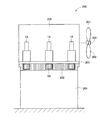
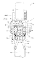
図1は、本発明の一実施形態に係る風車200の一例を示す概略断面図である。本例の風車200は、タワー201と、タワー201によって回転可能に支持されるナセル204と、ナセル204にハブ206を介して取り付けられる複数のブレード203とを備える。
[Windmill]
FIG. 1 is a schematic cross-sectional view showing an example of a
タワー201は地上に設置されるベース部であり、タワー201の内側には回転駆動ギアとして形成される内歯歯車型のリングギア202が固定的に取り付けられている。ナセル204には、当該ナセル204に固定的に取り付けられる回転架台205と、当該回転架台205に取り付けられる複数の風車駆動装置1Aとが設けられている。各風車駆動装置1Aは、回転架台205に形成された孔から突出してリングギア202と噛み合うピニオン101を具備する。リングギア202の内側の周方向に沿ってピニオン101が複数箇所に配置されるように、各風車駆動装置1Aはナセル204内において位置決めされる。したがって複数の風車駆動装置1Aのモータが相互に同期して動力軸を回転させて、各風車駆動装置1Aのピニオン101を回転駆動することで、回転架台205とともにナセル204全体がタワー201に対して回転駆動(旋回駆動)される。これにより、ナセル204に取り付けられるハブ206及びブレード203の向きが変えられる。なお複数の風車駆動装置1Aのモータ間における動力軸の回転同期は、例えば、複数の風車駆動装置1Aにコントローラを接続し、当該コントローラによって各モータを制御することで行われうる。またナセル204には、ハブ206に連結される動力伝達軸、増速機、発電機及びコンバーター等が更に設けられる。
The
ハブ206は、ナセル204に対して回転可能に取り付けられるとともに、複数のブレード203が軸部を介して取り付けられ、これらのブレード203は相互間の角度が均等となるように配置されている。各ブレード203は、軸部を中心にハブ206に対してピッチ方向に回転可能に設けられ、ピッチ駆動装置により回転駆動されてピッチ角が適宜変えられる。なお本例ではピッチ駆動装置の図示を省略するが、ピッチ駆動装置の構成は特に限定されず、例えば後述の風車駆動装置1Aと同様の構成を有するピッチ駆動装置によって各ブレード203を回転駆動することも可能である。
The
[風車駆動装置]
まず、本実施形態に係る風車駆動装置1Aの構成の概略について説明する。
[Windmill drive unit]
First, the outline of the structure of the
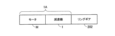
図2は、風車駆動装置1Aの構成例の概略を示す機能ブロック図である。本例の風車駆動装置1Aは、モータM及び減速機1を具備し、モータMから減速機1に供給される回転動力は、減速機1により減速されてトルクが増大され、リングギア202に伝達されてヨー駆動力に変換される。
FIG. 2 is a functional block diagram showing an outline of a configuration example of the
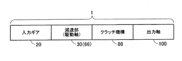
図3は、減速機1の構成例の概略を示す機能ブロック図である。本例の減速機1は、モータMが有する動力軸から動力が伝達され当該動力によって回転される入力ギア20と、入力ギア20に連結される減速部30と、上述のピニオン101が取り付けられる出力軸100と、減速部30と出力軸100との間に介在するクラッチ機構88とを含む。減速部30は、入力ギア20を介して動力軸から入力される動力により回転される駆動軸66を有する。出力軸100は、クラッチ機構88を介して減速部30の駆動軸66に連結され、駆動軸66から伝達される回転動力によって回転される。クラッチ機構88は、減速部30の駆動軸66から出力軸100への回転動力の伝達及び非伝達を切り換える。
FIG. 3 is a functional block diagram illustrating an outline of a configuration example of the
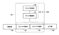
図4は、クラッチ機構88の構成例の概略を示す機能ブロック図である。本例のクラッチ機構88は、減速部30の駆動軸66と出力軸100との間に設けられる一対のクラッチ作動部89(クラッチ機構88)と、当該一対のクラッチ作動部89を制御するクラッチ制御部90とを有する。各クラッチ作動部89は駆動軸66及び出力軸100の各々に取り付けられており、駆動軸66に取り付けられるクラッチ作動部89と出力軸100に取り付けられるクラッチ作動部89との間の係合状態(固定状態)及び非係合状態(非固定状態)がクラッチ制御部90によって切り換えられる。本例のクラッチ制御部90は、駆動軸66に取り付けられるクラッチ作動部89及び出力軸100に取り付けられるクラッチ作動部89のうち少なくともいずれか一方に当接されるクラッチ駆動体91と、クラッチ駆動体91の移動をコントロールして一対のクラッチ作動部89の係合及び非係合を切り換えるクラッチ切換部92とを有する。またクラッチ制御部90には、風車駆動装置1Aに作用する外力を検知するセンサ装置209が接続され、風車駆動装置1Aに作用する外力の大きさに応じた検知信号がセンサ装置209からクラッチ制御部90に送られる。
FIG. 4 is a functional block diagram showing an outline of a configuration example of the
図2〜図4に示すような機能構成を有する上述の風車駆動装置1Aが想定外の過大な外力を受けた場合、センサ装置209からクラッチ制御部90に検知信号が送られる。そのような過大な外力を受けたことを示す検知信号をセンサ装置209から受信したクラッチ制御部90(クラッチ切換部92及びクラッチ駆動体91)は、一対のクラッチ作動部89間のクラッチを切る。すなわち一対のクラッチ作動部89が非係合状態にされ、駆動軸66と出力軸100とが非連結状態とされる。これにより駆動軸66から出力軸100に伝達される力の大きさが低減され、出力軸100、ピニオン101及びリングギア202等の破損などの故障を未然に防ぐことができる。
When the above-described wind
次に、上述の機能構成を有する風車駆動装置1Aの典型例について説明する。以下に示す例では、いわゆる偏心揺動型の減速部を備える風車駆動装置1Aに対して本発明が適用される。
Next, a typical example of the
図5は、風車駆動装置1Aの構成を例示する断面図である。本例の風車駆動装置1Aは、動力軸35を有するモータMと、動力軸35及びピニオン101の各々に連結され、動力軸35からピニオン101に動力を伝達する減速機1とを備える。この風車駆動装置1Aは、上述のように風車200(図1参照)のナセル204に設けられる回転架台205に対して堅固に固定される。
FIG. 5 is a cross-sectional view illustrating the configuration of the
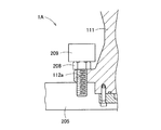
図6は、風車駆動装置1Aの部分拡大図であり、とりわけ回転架台205に対して風車駆動装置1Aを固定する箇所を示す図である。本例では、風車駆動装置1Aのメインケース部11aの入力側部分111に形成される複数のボルト穴112aの各々に締結ボルト208が挿入され、当該締結ボルト208によって風車駆動装置1Aが回転架台205に固定される。これらの複数の締結ボルト208のうちの少なくとも1つにはセンサ装置209が取り付けられ、締結ボルト208に作用する力がセンサ装置209によって検知され、検知信号がセンサ装置209からクラッチ制御部90に送られる(図4参照)。
FIG. 6 is a partially enlarged view of the
例えば図1に示す風車200に対して突風が吹き付けて風車200に対して急に過大な外力が加わった場合、ナセル204が回動する。この際、風車駆動装置1Aの出力軸100に取り付けられたピニオン101がリングギア202に係合しているため、回転架台205上で風車駆動装置1Aが傾いてしまう場合があり、この風車駆動装置1Aの傾きに応じて締結ボルト208には軸方向に力が作用する。
For example, when a gust of wind blows on the
締結ボルト208に取り付けられる本例のセンサ装置209は、締結ボルト208に作用するそのような軸方向の力を検知する。締結ボルト208に作用する軸方向の力から、回転架台205上における風車駆動装置1Aの傾き、ひいては風車駆動装置1Aに加わる外力を判断することが可能である。本実施形態では、クラッチ制御部90が、センサ装置209からの検知信号に基づいて締結ボルト208に作用する力の大きさや変化を監視及び判定する。そしてクラッチ制御部90は、センサ装置209からの検知信号に基づいてクラッチ作動部89を制御する。例えば締結ボルト208に作用する力が所定の大きさ以下と判定される場合、クラッチ制御部90はクラッチ作動部89におけるクラッチをつないだ状態を維持し、駆動軸66と出力軸100とを連結しておく。一方、所定の大きさよりも大きな力が締結ボルト208に作用すると判定される場合、クラッチ制御部90はクラッチ作動部89におけるクラッチを切り、駆動軸66と出力軸100との連結を解除する。
The
[減速機]
図5に示す減速機1は、モータMの動力軸35に連結される入力ギア20と、入力ギア20と噛み合う複数のスパーギア53と、複数のスパーギア53の各々に固定される複数のクランク軸50を有する偏心揺動型の減速部30と、一端部が減速部30に結合されるとともに他端部にクラッチ作動部89が取り付けられる駆動軸66と、クラッチ作動部89を介して駆動軸66に一端部が連結される出力軸100と、を備える。
[Decelerator]
The
減速部30は、内周側(内周面)に内歯12を有するケース10と、ケース10の内歯12と噛み合う外歯41を有する外歯歯車40と、外歯歯車40を保持するキャリア60と、クラッチ作動部89及び駆動軸66を介してキャリア60に連結されるとともにピニオン101に連結される出力軸100と、を有する。ケース10は、筒状に形成され、内側に入力ギア20、複数のスパーギア53、複数のクランク軸50、外歯歯車40及びキャリア60を収容する。外歯歯車40は、外歯用軸受(図示省略)を介して複数のクランク軸50を回転自在に保持し、入力ギア20及び複数のスパーギア53の回転に応じて複数のクランク軸50により揺動される揺動ギアとして機能する。キャリア60は、各クランク軸50を回転自在に保持するとともに、複数のクランク軸50を介して外歯歯車40を保持する。
The
上述の構成を有する減速機1では、モータMから入力ギア20に入力される回転動力が、減速部30により回転減速されて出力軸100から出力される。ケース10から突出する出力軸100の他端部にはピニオン101が設けられ、当該ピニオン101はリングギア202(図1参照)と噛み合うように配置されている。したがって入力ギア20及び減速部30を介して出力軸100に伝達される回転動力は、トルクが増大した状態でヨー駆動力としてピニオン101及びリングギア202に出力される。
In the
図5において符号「L1」は出力軸100の中心軸を示す。ケース10の内歯12が設けられる内周面の中心軸は、中心軸L1と同軸上に位置する。以下の説明において、単に「軸方向」として表される方向は、中心軸L1上を延びる方向又は中心軸L1に平行な方向を意味する。また、中心軸L1に直交する方向を「径方向」と呼び、中心軸L1周りの方向を「周方向」と呼ぶ。
In FIG. 5, “L1” indicates the central axis of the
ケース10は、筒状に形成され両端部が開放されたメインケース部11aと、メインケース部11aの一端部側に固定されるサブケース部11bと、を有する。本例ではメインケース部11aの縁部とサブケース部11bの縁部とがボルト(図示省略)によって固定されることにより、メインケース部11aとサブケース部11bとは連結される。メインケース部11aのうちサブケース部11bが装着される一端部とは反対側の他端部からは、出力軸100が突出する。メインケース部11aの一端部と他端部との間の中間部分の内周面には、径方向の内側に張り出す環状壁部11cが形成されている。
The
メインケース部11aは、環状壁部11cを基準に一端部側、すなわちサブケース部11b側に位置する入力側部分111と、環状壁部11cを基準に他端部側、すなわち出力軸100が突出する側に位置する出力側部分112と、を有する。入力側部分111には減速部30が収容され、入力側部分111の内周面には上述の内歯12が設けられている。また入力側部分111にはクラッチ作動部89が配置され、このクラッチ作動部89によって駆動軸66と出力軸100との間の連結状態及び非連結状態がコントロールされる。
The
内歯12は、ピン状に形成された複数の内歯ピンから構成されている。これらの内歯ピンは、メインケース部11aの入力側部分111の内周面の全域にわたって周方向に沿って等間隔に複数形成されたピン溝13に嵌め込まれ、各内歯ピンの長手方向が中心軸L1と平行になるように配置されている。このような構成を有する内歯12は、上述の外歯歯車40の外歯41と噛み合うように配置されている。
The
メインケース部11aの環状壁部11cには環状の第1軸受収容溝14が形成され、第1軸受収容溝14には、円錐ころ軸受などにより構成される第1軸受15が挿入されている。第1軸受15の外輪は、第1軸受収容溝14の底面に対して軸方向に当接又は近接するとともに、第1軸受収容溝14の側面に対して径方向に当接又は近接する。これにより、第1軸受15が第1軸受収容溝14に取り付けられている。
An annular first bearing housing groove 14 is formed in the
また、出力側部分112の他端部(外側端部)には環状の第2軸受収容溝16が形成され、第2軸受収容溝16には、円錐ころ軸受などにより構成される第2軸受17が挿入されている。第2軸受17の外輪は、第2軸受収容溝16の底面に対して軸方向に当接又は近接するとともに、第2軸受収容溝16の側面に対して径方向に当接又は近接する。これにより、第2軸受17が第2軸受収容溝16に取り付けられている。
An annular second bearing receiving groove 16 is formed at the other end (outer end) of the
そして第1軸受15の内輪の内周側及び第2軸受17の内輪の内周側に出力軸100が配置され、出力軸100がケース10に対して回転自在に保持される。出力軸100は第1軸受15からメインケース部11aの入力側部分111側に突出し、出力軸100のうち入力側部分111側に突出した部分が、クラッチ作動部89及び駆動軸66を介して減速部30に連結している。本例では、駆動軸66のうちの入力側部分111側に突出した部分の外周面に駆動軸側スプライン部102が形成され、この駆動軸側スプライン部102が減速部30のキャリア60に形成されたキャリア側スプライン部65と嵌合することで、駆動軸66と減速部30とが結合される。
The
ケース10のサブケース部11bにはモータMが取り付けられる。モータMが有する動力軸35はサブケース部11bの内側に向かって延在し、サブケース部11b内に配置される入力ギア20と固定的に接続され、モータMによって生み出される回転動力が動力軸35を介して入力ギア20に伝達される。
A motor M is attached to the
入力ギア20は平歯車構造を有し、モータMの動力軸35の中心軸及び入力ギア20の中心軸が出力軸100の中心軸L1上に位置する。入力ギア20は複数のスパーギア53の各々と噛み合うように配置され、動力軸35から入力ギア20に伝えられる回転動力が、複数のスパーギア53の各々に固定される複数のクランク軸50に伝達される。
The
減速部30を構成するキャリア60は、クランク軸50の一端部(入力ギア20及びスパーギア53側の端部)を回転自在に保持する第1保持部61と、クランク軸50の他端部(出力軸100が突出する側の端部)を回転自在に保持する第2保持部62と、第1保持部61と第2保持部62とを連結する支柱63と、キャリア60を駆動軸66と連結するための結合筒部64と、を有する。なお便宜上、図5において支柱63は二点鎖線により表される。
The
第1保持部61及び第2保持部62はそれぞれ円環状に形成され、第1保持部61と第2保持部62とは軸方向に関して離間した位置で互いに対向して配置される。支柱63は、第1保持部61の径方向の略中央領域と第2保持部62の径方向の略中央領域との間に跨がるように設けられ、第1保持部61と第2保持部62とを連結する。結合筒部64は、第1保持部61の内周縁と第2保持部62の内周縁との間に跨がるように設けられ、円筒形状を有し、内周面においてキャリア側スプライン部65が形成されている。上述のように、このキャリア側スプライン部65が駆動軸66の駆動軸側スプライン部102と嵌合することで、駆動軸66と減速部30とは結合される。
The first holding
第1保持部61には第1端部用貫通孔71が形成され、クランク軸50の一端部は、第1クランク軸用軸受73を介して第1端部用貫通孔71に回転自在に保持されている。また第2保持部62には第2端部用貫通孔72が形成され、クランク軸50の他端部は、第2クランク軸用軸受74を介して第2端部用貫通孔72に回転自在に保持されている。
A first end through
本例のキャリア60は軸方向で二分割され、サブケース部11b側に配置される第1半体60aと、出力軸100が突出する側に配置される第2半体60bとによって構成されている。第1半体60aは、上述の第1保持部61と、支柱63の一部を構成する第1支柱半部と、結合筒部64の一部を構成する第1筒半部64aと、を有する。一方、第2半体60bは、上述の第2保持部62と、支柱63の一部を構成する第2支柱半部と、結合筒部64の一部を構成する第2筒半部64bと、を有する。
The
第1支柱半部と第2支柱半部とにはボルト(図示省略)が跨がって挿入され、このボルトによって第1支柱半部と第2支柱半部とが連結されることで、第1半体60aと第2半体60bとが連結される。また、第1筒半部64a及び第2筒半部64bの各々の内周面には、上述のキャリア側スプライン部65が跨がって形成されている。
A bolt (not shown) is inserted across the first support column half and the second support column half, and the first support column half and the second support column half are connected by this bolt, The
各クランク軸50は、シャフト本体51と、当該シャフト本体51に設けられる偏心体(図示省略)とを有し、シャフト本体51の一端部にはスパーギア53が取り付けられる。すなわちシャフト本体51の一端部は第1端部用貫通孔71からサブケース部11b側に突出し、この第1端部用貫通孔71から突出するシャフト本体51の一端部にスパーギア53が固定されている。そして、シャフト本体51のうちスパーギア53と外歯歯車40との間に配置される一端側の部分は、第1クランク軸用軸受73を介して第1端部用貫通孔71に回転自在に保持され、シャフト本体51の他端側は、第2クランク軸用軸受74を介して第2端部用貫通孔72に回転自在に保持されている。
Each crankshaft 50 has a shaft body 51 and an eccentric body (not shown) provided on the shaft body 51, and a
クランク軸50がキャリア60により保持された状態において、クランク軸50の偏心体は、キャリア60の第1保持部61と第2保持部62との間に配置される。一方、第1保持部61と第2保持部62との間に設けられる外歯歯車40には、上述のキャリア60の支柱63を通すための支柱用貫通孔(図示省略)に加え、クランク軸50を挿入するためのクランク軸用貫通孔(図示省略)が軸方向と平行に形成されている。クランク軸50の偏心体は、クランク軸用軸受(図示省略)を介して外歯歯車40のクランク軸用貫通孔内に配置される。
In a state where the crankshaft 50 is held by the
外歯歯車40の外歯41は、ケース10の内周の内歯12の歯数よりも1個或いは複数個少なくなるように設けられている。このため、クランク軸50が回転するたびに外歯41と内歯12との噛み合いがずれ、外歯歯車40が偏心運動(クランク運動)して揺動回転する。
The
このような構成を有する減速機1において、モータMの動力軸35から伝えられる回転動力により入力ギア20が回転すると、入力ギア20に噛み合う各スパーギア53が回転し、各クランク軸50が回転する。各クランク軸50が回転することで、外歯歯車40が内歯12と噛み合いをずらしながら揺動するように偏心回転する。この外歯歯車40の偏心回転に伴って、各クランク軸50は自転しながら中心軸L1を中心とした公転動作を行う。このような外歯歯車40の揺動及び偏心回転に応じたクランク軸50の公転動作により、クランク軸50を保持するキャリア60が回転する。そしてこのキャリア60の回転に応じて、キャリア60にスプライン結合された駆動軸66が回転する。このようにしてモータMの動力軸35から駆動軸66に回転動力が伝達され、さらにクラッチ機構88を介して駆動軸66の回転動力が出力軸100に伝えられる。そして、出力軸100に設けられるピニオン101からリングギア202へトルクが伝達されることで、回転架台205を具備するナセル204及びブレード203の向きが変えられる。
In the
[クラッチ機構]
次に、クラッチ機構88の具体的な構成例について説明する。上述のようにクラッチ機構88はクラッチ作動部89及びクラッチ制御部90を具備し、クラッチ制御部90は、空圧方式及び油圧方式等の任意の動力によってクラッチ作動部89を駆動制御することが可能である。例えば図5に示す風車駆動装置1Aでは、油圧方式の動力によってクラッチ作動部89が駆動制御される。図5に示す例では、クラッチ油圧源94及びクラッチ切換部92等がサブケース部11bの上部に設置され、油等の液状伝達媒体が満たされる油圧供給路93によって、クラッチ油圧源94及びクラッチ切換部92とクラッチ駆動体91(油圧ピストン91a)とがつながれている。クラッチ駆動体91は、液状伝達媒体により押されて軸方向に移動可能に設けられており、クラッチ駆動体91の軸方向位置に応じてクラッチ作動部89に対するクラッチ駆動体91の当接状態(押圧状態)が変わる。クラッチ切換部92は、油圧供給路93内(特にクラッチ切換部92とクラッチ駆動体91との間)の液状伝達媒体の圧力を調整することでクラッチ作動部89に対するクラッチ駆動体91の押圧力を変えることができ、クラッチ作動部89のクラッチのオンオフを制御する。
[Clutch mechanism]
Next, a specific configuration example of the
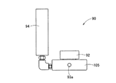
図7は、図5に示すクラッチ切換部92及びクラッチ油圧源94等を図5の矢印Sの方向から見た側面図である。理解を容易にするため、図7では油圧供給路93の図示が省略されている。本例のクラッチ制御部90は、油圧源本体105と、当該油圧源本体105に取り付けられるクラッチ切換部92及びクラッチ油圧源94とを有する。油圧供給路93は、油圧源本体105に設けられる供給管接続部93aを介して油圧源本体105内にも延在し、クラッチ油圧源94及びクラッチ切換部92の各々にも接続される。
FIG. 7 is a side view of the
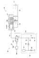
図8は、クラッチ機構88(クラッチ作動部89及びクラッチ制御部90)の機能構成例を示す図である。
FIG. 8 is a diagram illustrating a functional configuration example of the clutch mechanism 88 (the
本例のクラッチ作動部89は、第1連結部材107を介して駆動軸66に取り付けられる複数の第1摩擦板89aと、第2連結部材108を介して出力軸100に取り付けられる複数の第2摩擦板89bとを有する。第1摩擦板89a、第1連結部材107及び駆動軸66は、中心軸L1周りに一体的に回転するように、互いに係止される。同様に、第2摩擦板89b、第2連結部材108及び出力軸100は、中心軸L1周りに一体的に回転するように、互いに係止される。したがって第1摩擦板89aと第2摩擦板89bとが摩擦等により係合して中心軸L1周りに一体的に回転する場合、駆動軸66、第1連結部材107、第2連結部材108及び出力軸100も中心軸L1周りに一体的に回転する。
The
なお第1連結部材107及び第2連結部材108は、それぞれ第1摩擦板89a及び第2摩擦板89bを適切に支持することができればどのような構成であってもよく、単一部材によって構成されてもよいし、複数部材が組み合わされて構成されてもよい。例えば図5に示す例における第1連結部材107は、駆動軸66にスプライン結合するとともに第1摩擦板89aの各々にスプライン結合する部材によって構成されている。また第2連結部材108は、出力軸100にスプライン結合するとともに複数の第2摩擦板89bにスプライン結合する部材によって構成されている。第1摩擦板89a及び第2摩擦板89bは、それぞれ第1連結部材107及び第2連結部材108との結合が維持される範囲で、軸方向へわずかに移動可能に構成されている。
The first connecting
クラッチ制御部90は、図8に示すように、第1摩擦板89aと第2摩擦板89bとを係合させる(本例では摩擦により固定させる)ことで駆動軸66から出力軸100への回転動力の伝達を行い、第1摩擦板89aと第2摩擦板89bとの間の係合を解除することで駆動軸66から出力軸100への回転動力の非伝達を行う。
As shown in FIG. 8, the
本例のクラッチ制御部90は、クラッチ駆動体91として働く油圧ピストン91aを含み、当該油圧ピストン91aは第1摩擦板89a及び第2摩擦板89bのうち少なくともいずれか一方(本例では第2摩擦板89b)に当接する。油圧ピストン91aには、油圧供給路93を介してクラッチ油圧源94が接続される。油圧ピストン91aは、ピストンシリンダ構造を有し、クラッチ切換部92の制御下で、油圧供給路93内の液状伝達媒体の圧力に応じて、第1摩擦板89aに対する第2摩擦板89bの押し当て力を変えられる。すなわち油圧ピストン91aは、クラッチ切換部92の制御下で「第2摩擦板89bを第1摩擦板89aに押し当てて、第1摩擦板89aと第2摩擦板89bとを係合状態とする位置」及び「第2摩擦板89bを第1摩擦板89aに押し当てずに、第1摩擦板89aと第2摩擦板89bとを非係合状態とする位置」のいずれかに配置される。図5に示す例では、油圧ピストン91aと、油圧ピストン91aよりもモータM側において軸方向に関して固定的に配置される部材との間に、第1摩擦板89a及び第2摩擦板89bが配置され、油圧ピストン91aの軸方向位置に応じて第1摩擦板89a及び第2摩擦板89bの係合状態及び非係合状態の切り換えが行われる。
The
なお油圧ピストン91aによるピストンシリンダ構造は特に限定されず、例えば図5に示す例では、第1連結部材107、第2連結部材108及びクラッチ作動部89によって区画されるスペースに油圧ピストン91aが配置され、第1連結部材107及び第2連結部材108によって油圧ピストン91aの軸方向への移動がガイドされる。油圧ピストン91aと第2連結部材108との間にはOリング等のシーリング部材が配置され、油圧ピストン91aと第2連結部材108とによって区画され油圧供給路93内の液状伝達媒体が流入するスペースは液密構造を有し、当該スペースから外部への液状伝達媒体の漏出が防がれている。したがって油圧供給路93内の液状伝達媒体の圧力が相対的に高い場合、油圧ピストン91aは、当該液状伝達媒体によってクラッチ作動部89に向かって押され、第2摩擦板89bを第1摩擦板89aに押し当てる。一方、油圧供給路93内の液状伝達媒体の圧力が相対的に低い場合、油圧ピストン91aは、クラッチ作動部89から離れる方向に移動し、第2摩擦板89bは油圧ピストン91aによって第1摩擦板89aに押し当てられない。
The piston cylinder structure by the
このような油圧ピストン91aの移動は、クラッチ切換部92によりコントロールされる。すなわちクラッチ切換部92により、油圧供給路93内の液状伝達媒体を介して油圧ピストン91aの軸方向への移動がコントロールされ、第1摩擦板89aと第2摩擦板89bとの間の係合及び非係合が切り換えられる。具体的には図8に示すように、クラッチ切換部92は、油圧ピストン91aとクラッチ油圧源94との間の油圧供給路93に設けられ電磁弁によって構成される圧力調整弁92aと、センサ装置209に接続され、圧力調整弁92aの消磁(非通電)及び励磁(通電)をコントロールする通電コントローラ92bと、を有する。
Such movement of the
圧力調整弁92aは、油圧ピストン91aに対する液状伝達媒体の圧力を調整する。具体的には、圧力調整弁92aは弁状態を「油圧供給路93の密閉状態を維持したまま油圧供給路93内の液状伝達媒体の流通を許容する状態(開弁状態)」及び「油圧供給路93内の液状伝達媒体の一部を外部ドレンに逃がして油圧供給路93内の液状伝達媒体の圧力を解放する状態(圧力解放状態)」のいずれかに切り換える。図8に示す例では、消磁状態の圧力調整弁92aは開弁状態に置かれ、励磁状態の圧力調整弁92aは圧力解放状態に置かれる。
The
通電コントローラ92bは、センサ装置209からの検知信号に基づいて圧力調整弁92aの消磁及び励磁の状態をコントロールする。例えば、センサ装置209からの検知信号が「締結ボルト208に作用する力が所定の大きさ以下」を示す場合、通電コントローラ92bは圧力調整弁92aを通電せずに消磁状態として開弁状態とする。一方、センサ装置209からの検知信号が「締結ボルト208に作用する力が所定の大きさよりも大きい」ことを示す場合、通電コントローラ92bは圧力調整弁92aに電圧を印加して通電することで圧力調整弁92aを励磁状態として圧力解放状態とする。
The
したがって、特に異常がなく「締結ボルト208に作用する力が所定の大きさ以下」の間は、圧力調整弁92aは開弁状態に置かれ、油圧供給路93内の液状伝達媒体が油圧ピストン91aを押圧して第2摩擦板89bが第1摩擦板89aに押し当てられて係合する。この場合、第1摩擦板89a及び第2摩擦板89bの係合によって駆動軸66と出力軸100とは連結され、駆動軸66の回転動力が、第1連結部材107、第1摩擦板89a、第2摩擦板89b及び第2連結部材108を介して出力軸100に伝達される。
Accordingly, while there is no abnormality and “the force acting on the
一方、風車駆動装置1Aに過大な力が働いて「締結ボルト208に作用する力が所定の大きさよりも大きくなった」場合には、圧力調整弁92aは圧力解放状態に置かれ、油圧供給路93内の液状伝達媒体による油圧ピストン91aの押圧が解放され、第1摩擦板89aと第2摩擦板89bとの係合が解除される。これにより、駆動軸66と出力軸100とは非連結状態となり、出力軸100に取り付けられるピニオン101やピニオン101に係合するリングギア202の破損を未然に防ぐことができる。
On the other hand, when an excessive force is applied to the
なお本実施形態におけるクラッチ油圧源94は、アキュムレータ95と、油圧供給路93に液状伝達媒体を補給可能な補給口96と、当該補給口96とアキュムレータ95との間に設けられる逆止弁97とを有する。アキュムレータ95は、リリーフ弁98を介して油圧供給路93に連結されるとともに、ドレン弁99が連結されている。逆止弁97は、油圧供給路93内の液状伝達媒体が補給口96から流出するのを防ぐ。
In this embodiment, the clutch
このように本例のクラッチ油圧源94はアキュムレータ95によって構成されるため、ポンプ等を使った油圧源よりも構成を簡素化することができる。また、たとえ圧力調整弁92aが圧力開放状態に置かれて駆動軸66と出力軸100とが非連結状態となっても、圧力調整弁92aを開弁状態に戻し、補給口96を介して新たな液状伝達媒体を油圧供給路93に供給することで、第1摩擦板89aと第2摩擦板89bとを再度係合させて、駆動軸66と出力軸100とを連結状態に戻すことができる。
Thus, since the clutch
[他の変形例]
本発明は上述の実施形態に限定されず、種々の変形が加えられてもよい。
[Other variations]
The present invention is not limited to the above-described embodiment, and various modifications may be added.
例えば、駆動軸66から出力軸100への回転動力の伝達及び非伝達を切り換える「クラッチ機構88(クラッチ作動部89及びクラッチ制御部90)」の具体的な構成及び配置は、特に限定されない。上述の例ではクラッチ作動部89(第1摩擦板89a及び第2摩擦板89b)が中心軸L1から離間した位置に設けられているが、例えば中心軸L1上にクラッチ作動部89が設けられてもよい。この場合、「駆動軸66のうちの出力軸100側端面」及び「出力軸100のうちの駆動軸66側端面」の各々にクラッチ作動部89(摩擦板等)が設けられてもよい。
For example, the specific configuration and arrangement of the “clutch mechanism 88 (
このようなケースにおいて、センサ装置209からの検知信号が「締結ボルト208に作用する力が所定の大きさ以下」を示す場合、「駆動軸66のうちの出力軸100側端面のクラッチ作動部89」と「出力軸100のうちの駆動軸66側端面のクラッチ作動部89」とが相互に係合するように、駆動軸66及び出力軸100の相対位置がクラッチ制御部によってコントロールされる。これにより駆動軸66の回転動力がクラッチ作動部89を介して出力軸100に伝達される。一方、センサ装置209からの検知信号が「締結ボルト208に作用する力が所定の大きさよりも大きい」ことを示す場合、「駆動軸66のうちの出力軸100側端面のクラッチ作動部89」と「出力軸100のうちの駆動軸66側端面のクラッチ作動部89」とが相互に離間して係合が解除されるように、駆動軸66及び出力軸100の相対位置がクラッチ制御部によってコントロールされる。これにより駆動軸66の回転動力が出力軸100に伝達されることを防ぐことができる。
In such a case, when the detection signal from the
また上述の例では、クラッチ切換部92及びクラッチ油圧源94等のクラッチ機構88の一部がケース10の外部に設けられているが、クラッチ機構88(クラッチ作動部89及びクラッチ制御部90)を構成するこれらの要素を含む各部はケース10の内部に設けられてもよい。したがって例えば駆動軸66及び/又は出力軸100の内部に、クラッチ機構88を構成する要素の一部又は全部が配置されてもよい。
In the above example, a part of the
また上述の例では、異常状態を検出するためのセンサ装置209が、風車駆動装置1Aを据え付けるための締結具208の状態変化を計測し、クラッチ制御部90が、このセンサ装置209の検出結果に基づいてクラッチ作動体89を制御する例を示したが、この例に限られない。センサ装置209は、例えば駆動軸66及び/又は出力軸100のトルクを計測するように設けられてもよいし、ケース10の歪みを計測するように設けられてもよいし、モータの電流値を計測するように設けられてもよいし、風車の可動部の動作を制動するための制動動作の異常を検出するように設けられてもよい。
In the above-described example, the
また上述の例ではアキュムレータ95を使ってクラッチ油圧源94が構成されているが、油圧ポンプ等によってクラッチ油圧源94が構成されてもよい。
In the above example, the clutch
また上述の例では偏心揺動型の減速部30を具備する風車駆動装置1Aに本発明が適用されているが、他の方式の減速部を具備する風車駆動装置1Aに本発明が適用されてもよい。例えば偏心揺動型の減速部30の代わりに遊星歯車型等の他の減速部が設けられてもよく、モータMの動力軸35から当該他の減速部に回転動力が伝達され、減速されてトルクが増大した回転動力が当該他の減速部から駆動軸66に伝達される風車駆動装置1Aに対しても本発明を適用できる。また、上述の偏心揺動型の減速部30に加え、遊星歯車型等の他の減速部が設けられてもよい。例えばモータMの動力軸35から当該他の減速部に回転動力が伝達され、減速されてトルクが増大した回転動力が当該他の減速部から入力ギア20を介して偏心揺動型の減速部30に伝達される風車駆動装置1Aに対しても本発明を適用できる。これらの場合であっても、駆動軸66から出力軸100への回転動力の伝達及び非伝達をクラッチ機構88により切り換えることによって、部品の破損等の故障を未然に防ぐことができる。
In the above-described example, the present invention is applied to the
本発明は、上述した個々の実施形態に限定されるものではなく、当業者が想到しうる種々の変形も含むものであり、本発明の効果も上述した内容に限定されない。すなわち、特許請求の範囲に規定された内容及びその均等物から導き出される本発明の概念的な思想と趣旨を逸脱しない範囲で種々の追加、変更及び部分的削除が可能である。 The present invention is not limited to the individual embodiments described above, and includes various modifications that can be conceived by those skilled in the art, and the effects of the present invention are not limited to the contents described above. That is, various additions, changes, and partial deletions can be made without departing from the concept and spirit of the present invention derived from the contents defined in the claims and equivalents thereof.
1 減速機
1A 風車駆動装置
10 ケース
11a メインケース部
11b サブケース部
11c 環状壁部
12 内歯
13 ピン溝
14 第1軸受収容溝
15 第1軸受
16 第2軸受収容溝
17 第2軸受
20 入力ギア
30 減速部
35 動力軸
40 外歯歯車
41 外歯
50 クランク軸
51 シャフト本体
53 スパーギア
60 キャリア
60a 第1半体
60b 第2半体
61 第1保持部
62 第2保持部
63 支柱
64 結合筒部
64a 第1筒半部
64b 第2筒半部
65 キャリア側スプライン部
66 駆動軸
71 第1端部用貫通孔
72 第2端部用貫通孔
73 第1クランク軸用軸受
74 第2クランク軸用軸受
88 クラッチ機構
89 クラッチ作動部
89a 第1摩擦板
89b 第2摩擦板
90 クラッチ制御部
91 クラッチ駆動体
91a 油圧ピストン
92 クラッチ切換部
92a 圧力調整弁
92b 通電コントローラ
93 油圧供給路
93a 供給管接続部
94 クラッチ油圧源
95 アキュムレータ
96 補給口
97 逆止弁
98 リリーフ弁
99 ドレン弁
100 出力軸
101 ピニオン
102 駆動軸側スプライン部
105 油圧源本体
107 第1連結部材
108 第2連結部材
111 入力側部分
112 出力側部分
112a ボルト穴
200 風車
201 タワー
202 リングギア
203 ブレード
204 ナセル
205 回転架台
206 ハブ
208 締結ボルト
209 センサ装置
M モータ
DESCRIPTION OF SYMBOLS 1 Reduction gear 1A Windmill drive device 10 Case 11a Main case part 11b Sub case part 11c Annular wall part 12 Internal tooth 13 Pin groove 14 First bearing accommodation groove 15 First bearing 16 Second bearing accommodation groove 17 Second bearing 20 Input gear 30 Speed reducer 35 Power shaft 40 External gear 41 External gear 50 Crankshaft 51 Shaft body 53 Spur gear 60 Carrier 60a First half 60b Second half 61 First holding portion 62 Second holding portion 63 Support column 64 Connecting cylinder portion 64a First cylinder half part 64b Second cylinder half part 65 Carrier-side spline part 66 Drive shaft 71 First end through hole 72 Second end through hole 73 First crankshaft bearing 74 Second crankshaft bearing 88 Clutch mechanism 89 Clutch operating portion 89a First friction plate 89b Second friction plate 90 Clutch control portion 91 Clutch drive body 91a Hydraulic piston 92 Clutch disengagement Replacement portion 92a Pressure adjusting valve 92b Energizing controller 93 Hydraulic supply path 93a Supply pipe connecting portion 94 Clutch hydraulic source 95 Accumulator 96 Supply port 97 Check valve 98 Relief valve 99 Drain valve 100 Output shaft 101 Pinion 102 Drive shaft side spline portion 105 Hydraulic pressure Source body 107 First connecting member 108 Second connecting member 111 Input side portion 112 Output side portion 112a Bolt hole 200 Windmill 201 Tower 202 Ring gear 203 Blade 204 Nacelle 205 Rotating base 206 Hub 208 Fastening bolt 209 Sensor device M Motor
Claims (10)
前記動力軸から動力が伝達され当該動力によって回転される入力ギアと、
前記入力ギアを介して入力される動力によって回転される駆動軸を有する減速部と、
前記駆動軸から伝達される回転動力によって回転される出力軸と、
前記駆動軸から前記出力軸への回転動力の伝達及び非伝達を切り換えるクラッチ機構とを備える風車駆動装置。 A motor having a power shaft;
An input gear to which power is transmitted from the power shaft and rotated by the power;
A speed reducer having a drive shaft rotated by power input via the input gear;
An output shaft rotated by rotational power transmitted from the drive shaft;
A windmill drive device comprising: a clutch mechanism that switches between transmission and non-transmission of rotational power from the drive shaft to the output shaft.
前記クラッチ制御部は、前記第1摩擦板と前記第2摩擦板とを係合させることで前記駆動軸から前記出力軸への回転動力の伝達を行い、前記第1摩擦板と前記第2摩擦板との間の係合を解除することで前記駆動軸から前記出力軸への回転動力の非伝達を行う請求項2に記載の風車駆動装置。 The clutch operating part has a first friction plate attached to the drive shaft, and a second friction plate attached to the output shaft,
The clutch control unit transmits rotational power from the drive shaft to the output shaft by engaging the first friction plate and the second friction plate, and the first friction plate and the second friction plate. The windmill drive device according to claim 2, wherein non-transmission of rotational power from the drive shaft to the output shaft is performed by releasing the engagement with the plate.
前記クラッチ切換部は、液状伝達媒体を介して前記油圧ピストンの移動をコントロールして前記第1摩擦板と前記第2摩擦板との間の係合及び非係合を切り換える請求項4に記載の風車駆動装置。 The clutch driver includes a hydraulic piston,
5. The clutch switching unit according to claim 4, wherein the clutch switching unit controls engagement and disengagement between the first friction plate and the second friction plate by controlling movement of the hydraulic piston via a liquid transmission medium. Windmill drive device.
前記クラッチ切換部は、前記クラッチ駆動体と前記クラッチ油圧源との間の前記油圧供給路に設けられる圧力調整弁であって、前記クラッチ駆動体に対する前記液状伝達媒体の圧力を調整する圧力調整弁を有する請求項5に記載の風車駆動装置。 The clutch control unit further includes a clutch hydraulic pressure source connected to the clutch driver through a hydraulic pressure supply path filled with the liquid transmission medium.
The clutch switching unit is a pressure adjustment valve provided in the hydraulic pressure supply path between the clutch driver and the clutch hydraulic power source, and adjusts the pressure of the liquid transmission medium with respect to the clutch driver. The windmill drive device according to claim 5 having.
内周側に内歯を有するケースと、
前記内歯に噛み合う外歯を有する外歯歯車と、
前記入力ギアの回転に応じて前記外歯歯車を揺動するクランク軸と、
前記外歯歯車の揺動に応じて回転するキャリアであって、前記駆動軸に連結されるキャリアと、を更に有する請求項1〜8のいずれか一項に記載の風車駆動装置。 The deceleration part is
A case having internal teeth on the inner peripheral side;
An external gear having external teeth meshing with the internal teeth;
A crankshaft that swings the external gear according to the rotation of the input gear;
The windmill drive device according to any one of claims 1 to 8, further comprising a carrier that rotates in response to swinging of the external gear and is connected to the drive shaft.
内周側に内歯を有するケースと、
前記内歯に噛み合う外歯を有する外歯歯車と、
前記入力ギアの回転に応じて前記外歯歯車を揺動するクランク軸と、
前記外歯歯車の揺動に応じて回転するキャリアと、
前記キャリアに連結され、前記キャリアの回転に応じて回転する駆動軸と、
前記駆動軸から伝達される回転動力により回転される出力軸と、
前記駆動軸から前記出力軸への回転動力の伝達及び非伝達を切り換えるクラッチ機構と、を備える減速機。 An input gear to which power is transmitted from the power shaft and rotated by the power;
A case having internal teeth on the inner peripheral side;
An external gear having external teeth meshing with the internal teeth;
A crankshaft that swings the external gear according to the rotation of the input gear;
A carrier that rotates in response to oscillation of the external gear;
A drive shaft coupled to the carrier and rotating in accordance with the rotation of the carrier;
An output shaft rotated by rotational power transmitted from the drive shaft;
And a clutch mechanism that switches between transmission and non-transmission of rotational power from the drive shaft to the output shaft.
Priority Applications (3)
| Application Number | Priority Date | Filing Date | Title |
|---|---|---|---|
| JP2016081308A JP2017190838A (en) | 2016-04-14 | 2016-04-14 | Windmill drive device and reduction gear |
| EP17166243.0A EP3232053A1 (en) | 2016-04-14 | 2017-04-12 | Wind turbine drive device and reduction gear |
| CN201710245514.7A CN107299961A (en) | 2016-04-14 | 2017-04-14 | Windmill drive device and decelerator |
Applications Claiming Priority (1)
| Application Number | Priority Date | Filing Date | Title |
|---|---|---|---|
| JP2016081308A JP2017190838A (en) | 2016-04-14 | 2016-04-14 | Windmill drive device and reduction gear |
Publications (1)
| Publication Number | Publication Date |
|---|---|
| JP2017190838A true JP2017190838A (en) | 2017-10-19 |
Family
ID=58992603
Family Applications (1)
| Application Number | Title | Priority Date | Filing Date |
|---|---|---|---|
| JP2016081308A Pending JP2017190838A (en) | 2016-04-14 | 2016-04-14 | Windmill drive device and reduction gear |
Country Status (3)
| Country | Link |
|---|---|
| EP (1) | EP3232053A1 (en) |
| JP (1) | JP2017190838A (en) |
| CN (1) | CN107299961A (en) |
Cited By (1)
| Publication number | Priority date | Publication date | Assignee | Title |
|---|---|---|---|---|
| WO2019065791A1 (en) | 2017-09-29 | 2019-04-04 | 武田薬品工業株式会社 | Heterocyclic compound |
Families Citing this family (3)
| Publication number | Priority date | Publication date | Assignee | Title |
|---|---|---|---|---|
| JP7540886B2 (en) * | 2019-11-22 | 2024-08-27 | ナブテスコ株式会社 | Drive unit and electric power steering device |
| JP7520542B2 (en) * | 2020-03-24 | 2024-07-23 | ナブテスコ株式会社 | Torque estimation device, torque estimation method, and torque estimation program |
| CN118008690B (en) * | 2024-01-29 | 2024-07-30 | 上海东芯建筑工程技术有限公司 | Wind power generation system and protection device thereof |
Family Cites Families (11)
| Publication number | Priority date | Publication date | Assignee | Title |
|---|---|---|---|---|
| SE506573C2 (en) * | 1996-05-07 | 1998-01-12 | Aegir Konsult Ab | Gear unit for a machinery and wind turbine comprising a gear unit |
| CN102705162B (en) * | 2003-08-12 | 2014-10-22 | 纳博特斯克株式会社 | Yaw drive device for wind power generator |
| JP2009257263A (en) * | 2008-04-18 | 2009-11-05 | Nabtesco Corp | Yaw driving device of wind turbine |
| JP5543832B2 (en) * | 2010-04-16 | 2014-07-09 | ナブテスコ株式会社 | Windmill drive |
| JP5630816B2 (en) * | 2010-10-15 | 2014-11-26 | 庄司 勝治 | Decelerator with self-locking function |
| JP5474866B2 (en) * | 2011-04-22 | 2014-04-16 | 住友重機械工業株式会社 | Reduction gear used for wind power generation equipment |
| CN202082348U (en) * | 2011-06-16 | 2011-12-21 | 重庆妙奇丰科技有限公司 | Yaw speed reducer |
| US20140041474A1 (en) * | 2012-08-10 | 2014-02-13 | General Electric Company | Overload slip mechanism for the yaw drive assembly of a wind turbine |
| DE102013101011A1 (en) * | 2013-02-01 | 2014-08-07 | 2-B Energy Holding B.V. | Control device for a yaw system of a wind turbine |
| JP6076815B2 (en) | 2013-04-19 | 2017-02-08 | ナブテスコ株式会社 | Decelerator |
| JP6138012B2 (en) * | 2013-09-27 | 2017-05-31 | 住友重機械工業株式会社 | Yaw drive system for wind power generation equipment |
-
2016
- 2016-04-14 JP JP2016081308A patent/JP2017190838A/en active Pending
-
2017
- 2017-04-12 EP EP17166243.0A patent/EP3232053A1/en not_active Withdrawn
- 2017-04-14 CN CN201710245514.7A patent/CN107299961A/en active Pending
Cited By (1)
| Publication number | Priority date | Publication date | Assignee | Title |
|---|---|---|---|---|
| WO2019065791A1 (en) | 2017-09-29 | 2019-04-04 | 武田薬品工業株式会社 | Heterocyclic compound |
Also Published As
| Publication number | Publication date |
|---|---|
| EP3232053A1 (en) | 2017-10-18 |
| CN107299961A (en) | 2017-10-27 |
Similar Documents
| Publication | Publication Date | Title |
|---|---|---|
| CN100529362C (en) | Electrically driven camshaft adjuster | |
| KR101297887B1 (en) | Wind turbine generator, gear transmission mechanism, and method of controlling engagement of gears | |
| JP6033622B2 (en) | Windmill drive | |
| JP2017190838A (en) | Windmill drive device and reduction gear | |
| AU2009242395B2 (en) | Variable ratio gear | |
| WO2012046619A1 (en) | Wet brake device | |
| WO2012023231A1 (en) | Electro-hydraulic drive system for a work machine | |
| US9890767B2 (en) | Wind energy system with a pitch adjustment system | |
| JP4600379B2 (en) | Valve timing adjustment device | |
| JP6771935B2 (en) | Wind power generator | |
| JP2012225490A (en) | Speed reducer used for wind power generation facility | |
| CN110214228A (en) | Tuning and/or drive unit, wind turbine with such a tuning and/or drive unit and method for controlling such a tuning and/or drive unit | |
| CN102844565A (en) | Drive unit for windmill | |
| EP2759702A1 (en) | Renewable energy-type electric power generation device and method for operating renewable energy-type electric power generation device | |
| JP4229765B2 (en) | Wind turbine blade pitch angle control device | |
| US10132362B2 (en) | Power generation device and shaft coupling device with elastic member used therein | |
| JP6170321B2 (en) | Excavator | |
| JP2015197144A (en) | Swing driving device | |
| US20080220929A1 (en) | Engine-Driven Vehicle Having a Gear Mechanism for an Auxiliary Unit, in Particular as a Planetary Gear Set for Integration Into the Drive of the Auxiliary Unit, and Corresponding Gear Mechanism | |
| CN212480089U (en) | Sun gear axial limiting structure and planetary gear mechanism | |
| US10267399B2 (en) | Variable charge pump system for closed hydrostatic circuits | |
| US20100326222A1 (en) | Vibration exciter | |
| CN102537216A (en) | Special mechanical soft start transmission for chain hauled machinery | |
| KR101292184B1 (en) | Output control device for wind power generator | |
| JP6580402B2 (en) | Windmill drive |