JP2017190827A - Pressure adjusting drain valve - Google Patents
Pressure adjusting drain valve Download PDFInfo
- Publication number
- JP2017190827A JP2017190827A JP2016080136A JP2016080136A JP2017190827A JP 2017190827 A JP2017190827 A JP 2017190827A JP 2016080136 A JP2016080136 A JP 2016080136A JP 2016080136 A JP2016080136 A JP 2016080136A JP 2017190827 A JP2017190827 A JP 2017190827A
- Authority
- JP
- Japan
- Prior art keywords
- pressure
- liquid
- pressing force
- discharge port
- elastic member
- Prior art date
- Legal status (The legal status is an assumption and is not a legal conclusion. Google has not performed a legal analysis and makes no representation as to the accuracy of the status listed.)
- Granted
Links
Images
Landscapes
- Safety Valves (AREA)
Abstract
【課題】圧力調整弁と昇圧用・降圧用の昇降圧弁との2つの機能を有し、小型化してかつ流体の設定圧力を安定して保持し脈動を抑制する。【解決手段】圧力を調整する液体Qの流入口31および排出口32が形成された液体室3と、液体Qの圧力を調整する液体圧力調整機構4と、を有する圧力調整ドレン弁1であって、液体圧力調整機構4は、排出口32を閉塞または開放する弁体34と、排出口32を閉塞する方向に所定の押圧力Pを付与して弁体34を押圧する弾性部材5と、弾性部材5の後端部を支持する支持部材6と、支持部材6を弾性部材5の押圧方向に進退させて押圧力Pを調整するねじ部63を有する押圧力調整機構Fと、支持部材6を押圧方向に往復移動させるピストンシリンダ機構9を有する液体Qの昇降圧機構Tと、を備えた。【選択図】図1The present invention has two functions of a pressure regulating valve and a pressure increasing / decreasing pressure increasing / decreasing valve, which is reduced in size and stably maintains a set pressure of fluid to suppress pulsation. A pressure regulating drain valve (1) having a liquid chamber (3) in which an inlet (31) and an outlet (32) for a liquid Q for adjusting pressure are formed, and a liquid pressure adjusting mechanism (4) for adjusting the pressure of the liquid Q are provided. The liquid pressure adjustment mechanism 4 includes a valve body 34 that closes or opens the discharge port 32, an elastic member 5 that presses the valve body 34 by applying a predetermined pressing force P in the direction of closing the discharge port 32, and A supporting member 6 that supports the rear end portion of the elastic member 5; a pressing force adjusting mechanism F having a screw portion 63 that adjusts the pressing force P by moving the supporting member 6 back and forth in the pressing direction of the elastic member 5; And a step-up / down pressure mechanism T for the liquid Q having a piston cylinder mechanism 9 that reciprocally moves in the pressing direction. [Selection] Figure 1
Description
本発明は、液体の圧力を調整する圧力調整ドレン弁に係り、特に、圧力を調整する液体の流入口および排出口を備えた圧力調整ドレン弁に関する。 The present invention relates to a pressure adjusting drain valve that adjusts the pressure of a liquid, and more particularly to a pressure adjusting drain valve that includes a liquid inlet and outlet for adjusting the pressure.
一般的に、高圧ポンプによって高圧水等の高圧の液体を生成する高圧液体回路では、液体の圧力を調整する圧力調整弁、および昇圧用・降圧用の昇降圧弁(リリーフ弁やドレン弁)の2つの弁を別に設けて使用されることが多い。
また、従来、圧力調整弁と昇降圧弁との2つの機能を持たせた圧力調整弁が知られている(例えば、特許文献1,2)。
Generally, in a high-pressure liquid circuit that generates a high-pressure liquid such as high-pressure water by a high-pressure pump, there are two pressure regulation valves that adjust the pressure of the liquid, and step-up / down pressure valves (relief valves and drain valves) for boosting / decreasing pressure. Often used with two separate valves.
Conventionally, pressure regulating valves having two functions of a pressure regulating valve and a step-up / down pressure valve are known (for example,
特許文献1に記載された圧力調整弁は、弁体(22)と同軸に可動する制御ピストン(12)を設けて、弁ばねの力を変化させて最高圧力を調整することができる。制御ピストン(12)は、送出ポンプ(34)の圧力によって弁体(22)に対して位置を変えることができる。
The pressure regulating valve described in
特許文献2に記載された圧力調整弁は、高圧水の流通路に開口する弁孔(21)を開閉する弁体(4)をエアーシリンダー機構によって制御する。弁体(4)は、エアーシリンダー機構を構成するピストン(52)によって押圧され、所定圧力のもとに弁孔(21)を閉鎖する。ピストン(52)の移動速度は、ピストンロッド側の空室(51b)内に封入した圧縮エアの流出量を調整する流量調整弁(57)で制御する。
The pressure regulating valve described in
しかしながら、特許文献1に記載された圧力調整弁では、送出ポンプ(34)の圧力によって制御ピストン(12)の位置を変えて調整するため、脈動の影響を受けやすく、設定した圧力値に安定して保持しにくいという問題があった。
However, in the pressure regulating valve described in
特許文献2に記載された圧力調整弁では、エアーシリンダー機構を構成するピストンの移動を制御する圧縮エアのエア圧が不安定な場合には、高圧水の圧力が変動して安定しにくいという問題があった。
In the pressure regulating valve described in
そこで、本発明は、前記した問題点を解決すべく、一つの弁で液体の圧力を調整する圧力調整弁と昇圧用・降圧用の昇降圧弁との2つの機能を有し、安定して液体を設定圧力に昇圧して保持することができる圧力調整ドレン弁を提供することを課題とする。 Accordingly, the present invention has two functions of a pressure adjusting valve for adjusting the pressure of the liquid with a single valve and a step-up / step-down pressure valve for increasing and decreasing the pressure in order to solve the above-described problems, and stably It is an object of the present invention to provide a pressure regulating drain valve that can raise the pressure to a set pressure and hold it.
前記課題を解決するため、請求項1に係る発明は、圧力を調整する液体の流入口および前記液体を排出する排出口が形成された液体室と、前記排出口から所定流量の液体を排出して前記液体の圧力を調整する液体圧力調整機構と、を有する圧力調整ドレン弁であって、前記液体圧力調整機構は、前記排出口に対して進退自在に配設され当該排出口を閉塞または開放する弁体と、前記排出口を閉塞する方向に所定の押圧力を付与して前記弁体を押圧する弾性部材と、前記弾性部材の後端部を支持する支持部材と、この支持部材を前記弾性部材の押圧方向に進退させて前記押圧力を調整するねじ部を有する押圧力調整機構と、前記支持部材を前記押圧方向に往復移動させるピストンシリンダ機構を有する前記液体の昇降圧機構と、を備えたことを特徴とする。
In order to solve the above problems, the invention according to
本発明に係る圧力調整ドレン弁は、圧力を調整する液体(高圧水等)の流入口および前記液体を排出する排出口を有する液体室を備えたことで、排出口から液体を排出して迅速に降圧するドレン弁としての機能を有するとともに(降圧動作)、圧力を調整する液体の圧力が所定の圧力よりも高くなった場合には、前記排出口から所定流量の液体を排出して前記液体の圧力を調整する液体圧力調整機構を備えたことで、液体の圧力を所定の圧力に保持する圧力調整弁として機能を有する(昇圧動作および圧力調整動作)。 The pressure regulating drain valve according to the present invention includes a liquid chamber having an inlet for liquid (such as high-pressure water) for adjusting pressure and an outlet for discharging the liquid, thereby quickly discharging the liquid from the outlet. When the pressure of the liquid whose pressure is adjusted becomes higher than a predetermined pressure, the liquid at a predetermined flow rate is discharged from the discharge port to function as a drain valve that lowers the pressure to the lower pressure (pressure reduction operation). By providing the liquid pressure adjustment mechanism that adjusts the pressure of the liquid, it functions as a pressure adjustment valve that maintains the liquid pressure at a predetermined pressure (pressure increase operation and pressure adjustment operation).
このため、本発明に係る圧力調整ドレン弁は、昇降圧弁としての機能と圧力調整弁としての機能を一まとまりに構成することで、小型化して設置スペースを削減することができる。 For this reason, the pressure regulating drain valve according to the present invention can be reduced in size and reduced in installation space by configuring the function as the step-up / down pressure valve and the function as the pressure regulating valve together.
本発明に係る圧力調整ドレン弁において、前記液体圧力調整機構は、前記排出口を閉塞する方向に所定の押圧力を付与して前記弁体を押圧する弾性部材を備えたことで、所定の押圧力を安定して付与することができるため、安定して液体を設定圧力まで昇圧し(昇圧動作)、保持することができる(圧力調整動作)。また、前記液体圧力調整機構は、支持部材を進退させて押圧力を調整するねじ部を有する押圧力調整機構を備えたことで、簡易な構成で支持部材を進退させて押圧力を所定値に設定することができる(ねじ部による押圧力調整機能)。 In the pressure adjusting drain valve according to the present invention, the liquid pressure adjusting mechanism includes an elastic member that applies a predetermined pressing force in a direction to close the discharge port and presses the valve body. Since the pressure can be stably applied, the liquid can be stably raised to the set pressure (pressure increase operation) and held (pressure adjustment operation). In addition, the liquid pressure adjusting mechanism includes a pressing force adjusting mechanism having a screw portion that adjusts the pressing force by moving the supporting member forward and backward, so that the pressing force is set to a predetermined value by moving the supporting member forward and backward with a simple configuration. Can be set (pressing force adjustment function by screw part).
また、本発明に係る圧力調整ドレン弁は、前記支持部材を前記押圧方向に往復移動させるピストンシリンダ機構を備えたことで、前記液体の昇圧動作および降圧動作を迅速に行うことができる。 In addition, the pressure regulating drain valve according to the present invention includes a piston cylinder mechanism that reciprocates the support member in the pressing direction, so that the pressure raising operation and the pressure lowering operation of the liquid can be quickly performed.
つまり、ピストンシリンダ機構によって前記支持部材を後退させることで、前記押圧力を開放し前記排出口から前記液体を排出して、迅速かつ確実にドレン動作(降圧動作)を行うことができる。 That is, by retracting the support member by the piston cylinder mechanism, the pressing force is released, the liquid is discharged from the discharge port, and a drain operation (step-down operation) can be performed quickly and reliably.
また、ピストンシリンダ機構によって前記支持部材を押圧方向に前進させることで、弾性部材に対して所定の撓み量を与えることができるため、弾性部材が発生する押圧力を安定して保持することができる(昇圧動作および圧力調整動作)。 Moreover, since the predetermined deflection amount can be given to the elastic member by advancing the support member in the pressing direction by the piston cylinder mechanism, the pressing force generated by the elastic member can be stably held. (Pressure increase operation and pressure adjustment operation).
このようにして、本発明に係る圧力調整ドレン弁は、一つの弁で液体の圧力を調整する圧力調整弁と昇圧用・降圧用の昇降圧弁との2つの機能を有し、別に圧力調整弁またはリリーフ弁(ドレン弁)を設ける必要がなくなるとともに安定して液体を設定圧力まで昇圧して保持することができる。 In this way, the pressure regulating drain valve according to the present invention has two functions of a pressure regulating valve that regulates the pressure of liquid with one valve and a step-up / step-down valve for boosting / decreasing pressure. Alternatively, it is not necessary to provide a relief valve (drain valve), and the liquid can be stably raised to a set pressure and held.
請求項2に係る発明は、請求項1に記載の圧力調整ドレン弁であって、前記ピストンシリンダ機構は、シリンダと、このシリンダ内に収容されたピストンと、前記シリンダの後部に圧力流体を供給して前記ピストンを前進方向に移動させる圧力流体供給口と、前記ピストンの前進方向の移動を規制するストッパ部材と、を備え、前記支持部材は、前記ねじ部を介して前記ピストンに連結されていること、を特徴とする。
The invention according to
請求項2に係る発明によれば、前記シリンダの後部に圧力流体を供給して前記ピストンを前進方向に移動させる圧力流体供給口を備えたことで、圧力流体供給口から圧縮エア等の圧力流体を供給することによって前記支持部材を押圧方向に前進させることができる。
また、前記ピストンの前進方向の移動を規制するストッパ部材を備えたことで、前記ピストンの前進端を高精度に規制することができるため、弾性部材の撓み量を高精度に規制するとともに弾性部材が発生する押圧力をより安定して保持することができる。
According to the second aspect of the present invention, the pressure fluid supply port for supplying the pressure fluid to the rear portion of the cylinder and moving the piston in the forward direction is provided, so that the pressure fluid such as compressed air is supplied from the pressure fluid supply port. The supporting member can be moved forward in the pressing direction by supplying.
Moreover, since the stopper member for restricting the movement of the piston in the forward direction can be provided, the advance end of the piston can be regulated with high accuracy, so that the amount of bending of the elastic member is regulated with high accuracy and the elastic member. It is possible to more stably hold the pressing force generated.
また、前記圧力流体供給口から圧力流体を排出することで、前記押圧力を開放し前記排出口から前記液体を排出することができる。 Further, by discharging the pressure fluid from the pressure fluid supply port, the pressing force can be released and the liquid can be discharged from the discharge port.
請求項3に係る発明は、請求項1または請求項2に記載の圧力調整ドレン弁であって、ドレン動作において、前記昇降圧機構は、前記支持部材を後退させて前記押圧力を開放し前記排出口から前記液体を排出すること、を特徴とする。
The invention according to claim 3 is the pressure regulating drain valve according to
請求項3に係る発明によれば、ピストンシリンダ機構によって迅速かつ確実に前記押圧力を開放し前記排出口から前記液体を排出して降圧することができる。 According to the invention which concerns on Claim 3, the said pressing force can be open | released quickly and reliably by a piston cylinder mechanism, and the said liquid can be discharged | emitted from the said discharge port, and pressure-lowering can be carried out.
請求項4に係る発明は、請求項1から請求項3のいずれか1項に記載の圧力調整ドレン弁であって、圧力調整動作において、前記液体圧力調整機構は、前記昇降圧機構によって前記支持部材を前記弾性部材の押圧方向に移動させた状態で支持するとともに、前記弁体は前記弾性部材によって前記排出口を閉塞する方向に押圧力を受けながら当該排出口から所定流量の液体を排出して前記液体の圧力を調整すること、を特徴とする。 The invention according to a fourth aspect is the pressure regulating drain valve according to any one of the first to third aspects, wherein in the pressure regulating operation, the liquid pressure regulating mechanism is supported by the step-up / down pressure mechanism. The member is supported while being moved in the pressing direction of the elastic member, and the valve body discharges a predetermined flow rate of liquid from the discharge port while receiving a pressing force in the direction of closing the discharge port by the elastic member. And adjusting the pressure of the liquid.
請求項4に係る発明によれば、前記昇降圧機構によって前記支持部材を前記弾性部材の押圧方向に移動させた状態で支持することで、弾性部材に対して所定の撓み量を与えて、弾性部材が発生する押圧力を安定して保持することができる。 According to the fourth aspect of the invention, the support member is supported in a state in which the support member is moved in the pressing direction of the elastic member by the step-up / step-down mechanism, so that a predetermined amount of bending is given to the elastic member. The pressing force generated by the member can be stably held.
また、前記排出口を閉塞する方向に所定の押圧力を付与して前記弁体を押圧することで、前記液体の圧力に応じて前記排出口から所定流量の液体を排出して前記液体の圧力を調整することができる(余水ドレンによる圧力調整動作)。 Further, by applying a predetermined pressing force in the direction of closing the discharge port and pressing the valve body, a predetermined flow rate of liquid is discharged from the discharge port according to the pressure of the liquid, and the pressure of the liquid Can be adjusted (pressure adjustment operation by sewage drain).
本発明に係る圧力調整ドレンは、液体の圧力を調整する圧力調整弁と昇圧用・降圧用の昇降圧弁との2つの機能を有し、別に圧力調整弁またはリリーフ弁(ドレン弁)を設けることなく安定して液体を設定圧力まで昇圧して保持することができる。 The pressure adjusting drain according to the present invention has two functions of a pressure adjusting valve for adjusting the pressure of the liquid and a step-up / step-down valve for pressure increase / decrease, and a pressure control valve or a relief valve (drain valve) is provided separately. The liquid can be raised to the set pressure and held stably.
本発明の実施形態に係る圧力調整ドレン弁1について、適宜図面を参照しながら詳細に説明する。圧力調整ドレン弁1は、例えば、ウォータージェット加工機(不図示)等に使用する高圧の液体Q(高圧水)の圧力を調整する圧力調整機能付きのドレン弁である。圧力調整ドレン弁1は、圧力調整弁、並びに、昇圧および降圧を制御する昇降圧弁(リリーフ弁やドレン弁)の2つの機能を有する。
A pressure regulating
圧力を調整する液体Q(高圧水)は、例えば高圧ポンプ(不図示)等で生成され、液圧流路(不図示)を流通して、ウォータージェット加工機(不図示)の噴射ノズル(不図示)等まで供給される。 The liquid Q (high-pressure water) for adjusting the pressure is generated by, for example, a high-pressure pump (not shown) or the like and flows through a hydraulic pressure channel (not shown), and is an injection nozzle (not shown) of a water jet processing machine (not shown). ) Etc.
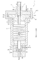
圧力調整ドレン弁1は、図1に示すように、円筒形状をなした筐体2と、筐体2の先端部(図1の下方)に配設された液体室3と、液体Qの圧力を調整する液体圧力調整機構4と、を備えている。
As shown in FIG. 1, the pressure adjusting
なお、本実施形態に係る圧力調整ドレン弁1において、説明の便宜上、筐体2の中心軸方向に対して液体室3が配設された部分を前部(図1の下方)といい、反対側(図1の上方)の部分を後部という。
In the pressure regulating
筐体2は、液体圧力調整機構4等の構成要素を収容するための基体となる部材である。
液体室3は、液圧流路(不図示)を流通する液体Qを導入するための空間であり、液体Qの流入口31と、流入口31から導入された液体Qを排出する排出口32と、を備えている。
The
The liquid chamber 3 is a space for introducing the liquid Q flowing through a hydraulic pressure channel (not shown), and includes an
液体室3では、流入口31から流入した液体Qを排出口32から排出する。液体圧力調整機構4は、液体Qの圧力に応じて所定量の液体Q1を排出口32から排出して、液体Qの圧力を調整(余水ドレン)する。
In the liquid chamber 3, the liquid Q flowing from the
液体圧力調整機構4は、排出口32の開口縁部に配設された弁座33と、排出口32を閉塞または開放させる弁体34と、排出口32を閉塞する方向に所定の押圧力Pを付与して弁体34を押圧する弾性部材5と、弾性部材5の後端部を支持する支持部材6と、支持部材6を弾性部材5の押圧方向に進退させて押圧力Pを調整するねじ部63を有する押圧力調整機構Fと、支持部材6を押圧方向に往復移動させるピストンシリンダ機構9を有する液体Qの昇降圧機構Tと、を備えている。
The liquid
弁座33は、排出口32の開口縁部に沿う形状をなした円環状の部材である。
弁体34は、弁座33に嵌入されて排出口32を閉塞する棒状をなした弁部34aと、弁部34aの先端部に形成された先細りのテーパ部34bと、弁部34aに連結された円板形状をなした弁体保持部34cと、を備えている。弁体34は、筐体2の内周部にガイドされるように弁座33に対して進退自在に収容されている。
The
The
テーパ部34bは、弁座33の内周部に当接するように挿通されて排出口32を閉塞することができる。弁体保持部34cは、弾性部材5の先端部に当接され、弾性部材5が発生する押圧力P(弁体34を弁座33に押し付ける力)を受け止める。
The tapered
テーパ部34bは、液体Qからの圧力を受けると弁体34を上向きに移動させる分力を発生させる。この上向きの分力は液体Qの圧力が高くなるほど大きくなる。そのため、液体Qの圧力が高くなり、分力が押圧力Pよりも大きくなると、液体Qの圧力の上昇とともに弁体34は徐々に後部方向へ移動して排出口32が開放され、排出口32からの余水ドレンQ1の量も増大する。また、液体Qの圧力が低くなるほど上向きの分力が小さくなるため、排出口32からの余水ドレンQ1の量は減少する。
The
液体Qの圧力と押圧力Pが均衡した状態のとき、弁体34は、排出口32に対して浮遊した状態で全開する。弁体34が全開になると、液体Qは設定圧力になる。換言すれば、液体Qの圧力に対して押圧力Pが均衡する位置まで弁体34は移動するため、液体Qの設定圧力と押圧力Pが均衡するように、押圧力調整機構Fによって押圧力Pの大きさを適正に調整することで、液体Qの設定圧力を調整できる。
When the pressure of the liquid Q and the pressing force P are in a balanced state, the
弾性部材5は、撓みやねじり等の弾性変形によって押圧力Pを発生する部材であり、コイルスプリングやゴムスプリング等の種々のばね部材を使用することができる。弾性部材5は、弾性部材5の先端部が弁体保持部34cに当接するように筐体2に収容されている。
The
支持部材6は、先端部が円板形状をなした弾性部材保持部61と、弾性部材保持部61の中心から筐体2の軸方向に沿って立設された軸部材62と、軸部材62に形成されたねじ部63と、を備えている。
弾性部材保持部61は、弾性部材5の後端部に当接している。ねじ部63は、支持部材6とピストンシリンダ機構9を構成するピストン92とを連結するとともに、ピストンシリンダ機構9と弾性部材保持部61との距離(位置関係)を調整する連結手段である。
The
The elastic
かかる構成により、弾性部材5は、外周部が筐体2の内側でガイドされ、先端部が弁体保持部34cで支持され、後端部が弾性部材保持部61で支持されている。
With this configuration, the
〈昇降圧機構〉
昇降圧機構Tは、昇圧動作および圧力調整動作を行う場合には、ピストンシリンダ機構9によって、支持部材6を弾性部材5の押圧方向に移動させる。昇圧後、液体Qの圧力が設定値よりも高くなると、排出口32から所定流量の液体Q1を排出して液体Qの圧力を調整する圧力調整動作に移行する。
<Bucking pressure mechanism>
When the pressure increasing / decreasing mechanism T performs the pressure increasing operation and the pressure adjusting operation, the piston /
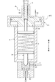
一方、降圧動作であるドレン動作(全量ドレン)を行う場合には、図2に示すように、支持部材6を後退させて押圧力Pを開放し弁体34を後部方向に移動させて排出口32を開き液体Q2を排出する。
なお、ドレン動作(全量ドレン)は、作業者が作業の終了時に行ってもよいし、予め所定のドレン圧を設定して、このドレン圧に到達したことを検知して自動的に行ってもよい。所定のドレン圧は、圧力調整ドレン弁1が使用される目的や仕様に応じて初期設定等によって適宜設定される。
On the other hand, in the case of performing a drain operation (total drainage) as a step-down operation, as shown in FIG. 2, the
The drain operation (total drainage) may be performed by the operator at the end of the work, or may be performed automatically by setting a predetermined drain pressure in advance and detecting that the drain pressure has been reached. Good. The predetermined drain pressure is appropriately set by initial setting or the like according to the purpose and specification of the use of the pressure adjusting
ピストンシリンダ機構9は、図1に示すように、筐体2の後部に固定されたシリンダ91と、シリンダ91内で筐体2の軸方向に往復移動自在に配設されたピストン92と、ピストン92の軸方向に形成されたねじ穴93と、ピストン92を前進方向に移動させる圧力流体供給口94と、を備えている。
As shown in FIG. 1, the
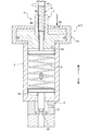
ピストンシリンダ機構9は、図示しない制御装置によって、圧力流体供給口94から圧力流体である圧縮エアAをシリンダ91内に供給してピストン92を前進方向に移動させる。また、圧縮エアAをシリンダ91内から開放するとピストン92を後退方向に移動する。ピストン92を前進方向に移動させると、排出口32を閉塞することが可能な状態になる。ピストン92が後退方向に移動すると、排出口32は開放される(図3参照)。
The
なお、「排出口32を閉塞することが可能な状態」とは、ピストン92が前進方向に移動して排出口32を閉塞することが可能な状態において、押圧力Pが作用している状態で、液体Qの圧力に応じて、所定量の液体Q1が排出口32から排出される状態(余水ドレン)を含む。すなわち、昇圧動作中において、液体圧力調整機構4により排出口32が開放されて余水ドレンが行われている状態(圧力調整動作)を含む。
The “state in which the
シリンダ91は、ピストン92の前進方向の移動を規制するストッパ部材である前壁91aと、ピストン92の後退方向の移動を規制する後壁91bと、ピストン92の外周部を往復移動自在にガイドするガイド壁91cと、を備えている。
The
ピストン92は、円盤状に形成された本体部92aと、本体部92aから後方に突出して形成されたボス部92bと、本体部92aの外周部に配設されたシール部材92cと、を備えている。
ねじ穴93は、ボス部92bに形成されている。ねじ穴93は、ねじ部63と螺合している。ねじ穴93とねじ部63を螺合することで、押圧力調整機構Fが機能する。
The
The
〈押圧力調整機構〉
押圧力調整機構Fは、弾性部材5が弁体34を弁座33に付勢する押圧力Pを調整する機構である。かかる構成により、ピストン92に対してねじ部63を回転させて支持部材6を弾性部材5の押圧方向に進退させて押圧力Pを調整する。
<Pressure adjusting mechanism>
The pressing force adjustment mechanism F is a mechanism that adjusts the pressing force P by which the
具体的には、液体Qの圧力を高く設定する場合、ねじ部63を前進方向にねじ込むことで、弾性部材5による押圧力Pを増大させる。また、図3に示すように、液体Qの圧力を低く設定したい場合、ねじ部63を後退方向に移動させて、弾性部材5による押圧力P1を減少させる(P1<P)。
Specifically, when the pressure of the liquid Q is set high, the pressing force P by the
例えば、図3に示すように、ねじ部63を後退方向に移動させて液体Qの圧力を低く設定した状態から、図1に示すように、ねじ部63を前進方向にねじ込むことで、弾性部材5による押圧力Pを増大させ、液体Qの圧力を設定する。弾性部材5の押圧力Pを図3に示す押圧力P1よりも大きく設定した場合には(P1<P)、排出口32から排出される所定量の液体Q1の排出量が少なくなるので液体Qの圧力は高くなる。
For example, as shown in FIG. 3, the
以上のように構成された圧力調整ドレン弁1の動作について、図1から図3を参照しながら説明する。
圧力調整ドレン弁1は、図1に示すように、昇圧動作および圧力調整動作を行う場合は、ピストンシリンダ機構9により、圧力流体供給口94から圧縮エアAをシリンダ91内に供給してピストン92を前壁91aに当接させて支持部材6を前進方向に移動させる。
The operation of the pressure regulating
As shown in FIG. 1, the pressure adjusting
支持部材6を前進方向(弾性部材5の押圧方向)に移動させると、弾性部材5が押圧されて押圧力Pを発生する。このように、支持部材6により支持された弾性部材5の押圧力Pによって、弁体34が排出口32を閉塞する。
When the
このとき、排出口32は押圧力調整機構Fにより設定した所定の押圧力Pで閉塞されるため、液体Qの圧力が設定値よりも高くなると排出口32から所定流量の液体Q1,Q2が排出され、液体Qの圧力が調整される(余水ドレンによる圧力調整動作)。
At this time, since the
[全量ドレン動作]
一方、ドレン動作(全量ドレン)を行う場合には、圧力調整ドレン弁1は、図3に示すように、昇降圧機構Tを構成するピストンシリンダ機構9によって、圧力流体供給口94内から圧縮エアAを開放することでピストン92を後壁91bに当接するよう移動させて支持部材6を後退させる。支持部材6を後退させることにより、排出口32を開放し、開放された排出口32から液体Q3を排出する。
[All drain operation]
On the other hand, when performing a drain operation (total amount drain), the pressure adjusting
以上のように構成された本実施形態に係る圧力調整ドレン弁1は、以下のような作用効果を奏する。
すなわち、圧力調整ドレン弁1は、ピストンシリンダ機構9によって支持部材6を後退させることで、排出口32に対する押圧力Pを開放し排出口32から液体Q3を排出して、迅速かつ確実にドレン動作(降圧動作)を行うことができる。
The pressure regulating
That is, the pressure adjusting
また、図1と図2に示すように、ピストンシリンダ機構9により、昇圧動作中においても弾性部材5に対して所定の撓み量を与え、弾性部材5が発生する押圧力Pを安定して保持できる(昇圧動作)。
Further, as shown in FIGS. 1 and 2, the
このようにして、圧力調整ドレン弁1は、一つの弁で液体Qの圧力を調整する圧力調整弁、および昇圧用・降圧用の昇降圧弁(ドレン弁)との2つの機能を有し、別に圧力調整弁またはリリーフ弁を設けることなく安定して液体Qを設定圧力まで昇圧して保持することができる。
In this way, the pressure regulating
以上、本発明の実施形態について説明したが、本発明は前記した実施形態に限定されず、適宜変更して実施することが可能である。
例えば、本実施形態においては、ピストンシリンダ機構9を作動させる圧力流体として圧縮エアAを使用したが、これに限定されるものではなく、油圧で作動させてもよい。
Although the embodiments of the present invention have been described above, the present invention is not limited to the above-described embodiments, and can be implemented with appropriate modifications.
For example, in the present embodiment, the compressed air A is used as the pressure fluid for operating the
1 圧力調整ドレン弁
2 筐体
3 液体室
4 液体圧力調整機構
5 弾性部材
6 支持部材
9 ピストンシリンダ機構
31 流入口
32 排出口
33 弁座
34 弁体
34a 弁部
34b テーパ部
34c 弁体保持部
61 弾性部材保持部
62 軸部材
63 ねじ部
91 シリンダ
91a 前壁(ストッパ部材)
91b 後壁
92 ピストン
93 ねじ穴
94 圧力流体供給口
A 圧縮エア(圧力流体)
F 押圧力調整機構
P,P1 押圧力
Q,Q1,Q2 液体
T 昇降圧機構
DESCRIPTION OF
F Pressure adjusting mechanism P, P1 Pressure Q, Q1, Q2 Liquid T Lifting pressure mechanism
Claims (4)
前記排出口から所定流量の液体を排出して前記液体の圧力を調整する液体圧力調整機構と、を有する圧力調整ドレン弁であって、
前記液体圧力調整機構は、
前記排出口に対して進退自在に配設され当該排出口を閉塞または開放させる弁体と、
前記排出口を閉塞する方向に所定の押圧力を付与して前記弁体を押圧する弾性部材と、
前記弾性部材の後端部を支持する支持部材と、
この支持部材を前記弾性部材の押圧方向に進退させて前記押圧力を調整するねじ部を有する押圧力調整機構と、
前記支持部材を前記押圧方向に往復移動させるピストンシリンダ機構を有する前記液体の昇降圧機構と、
を備えたことを特徴とする圧力調整ドレン弁。 A liquid chamber having a liquid inlet for adjusting pressure and an outlet for discharging the liquid; and
A pressure adjustment drain valve having a liquid pressure adjustment mechanism that discharges a predetermined flow rate of liquid from the discharge port and adjusts the pressure of the liquid,
The liquid pressure adjusting mechanism is
A valve body that is disposed so as to be movable back and forth with respect to the discharge port, and closes or opens the discharge port;
An elastic member that applies a predetermined pressing force in a direction to close the discharge port and presses the valve body;
A support member for supporting a rear end portion of the elastic member;
A pressing force adjusting mechanism having a screw portion that adjusts the pressing force by moving the supporting member forward and backward in the pressing direction of the elastic member;
A liquid pressure increasing / decreasing mechanism having a piston cylinder mechanism for reciprocating the support member in the pressing direction;
A pressure regulating drain valve characterized by comprising:
前記支持部材は、前記ねじ部を介して前記ピストンに連結されていること、
を特徴とする請求項1に記載の圧力調整ドレン弁。 The piston cylinder mechanism includes a cylinder, a piston housed in the cylinder, a pressure fluid supply port for supplying a pressure fluid to a rear portion of the cylinder and moving the piston in a forward direction, and a forward direction of the piston. A stopper member for restricting movement,
The support member is connected to the piston via the screw portion;
The pressure regulating drain valve according to claim 1.
を特徴とする請求項1または請求項2に記載の圧力調整ドレン弁。 In the drain operation, the step-up / step-down mechanism retreats the support member to release the pressing force and discharge the liquid from the discharge port.
The pressure regulating drain valve according to claim 1 or 2, wherein
を特徴とする請求項1から請求項3のいずれか1項に記載の圧力調整ドレン弁。 In the pressure adjustment operation, the liquid pressure adjustment mechanism supports the support member in a state where the support member is moved in the pressing direction of the elastic member by the step-up / down pressure mechanism, and the valve body closes the discharge port by the elastic member. Adjusting the pressure of the liquid by discharging a predetermined flow rate of liquid from the outlet while receiving a pressing force in the direction of
The pressure regulating drain valve according to any one of claims 1 to 3, wherein:
Priority Applications (1)
| Application Number | Priority Date | Filing Date | Title |
|---|---|---|---|
| JP2016080136A JP6529926B2 (en) | 2016-04-13 | 2016-04-13 | Pressure adjustment drain valve |
Applications Claiming Priority (1)
| Application Number | Priority Date | Filing Date | Title |
|---|---|---|---|
| JP2016080136A JP6529926B2 (en) | 2016-04-13 | 2016-04-13 | Pressure adjustment drain valve |
Publications (2)
| Publication Number | Publication Date |
|---|---|
| JP2017190827A true JP2017190827A (en) | 2017-10-19 |
| JP6529926B2 JP6529926B2 (en) | 2019-06-12 |
Family
ID=60085136
Family Applications (1)
| Application Number | Title | Priority Date | Filing Date |
|---|---|---|---|
| JP2016080136A Active JP6529926B2 (en) | 2016-04-13 | 2016-04-13 | Pressure adjustment drain valve |
Country Status (1)
| Country | Link |
|---|---|
| JP (1) | JP6529926B2 (en) |
Cited By (2)
| Publication number | Priority date | Publication date | Assignee | Title |
|---|---|---|---|---|
| CN114575426A (en) * | 2022-04-09 | 2022-06-03 | 谷力(厦门)科技有限公司 | Hydraulic drain valve with noise reduction function |
| CN115783426A (en) * | 2022-11-28 | 2023-03-14 | 福建美创富氢科技有限公司 | A pressure regulating canning mechanism |
Citations (3)
| Publication number | Priority date | Publication date | Assignee | Title |
|---|---|---|---|---|
| JPS57161374A (en) * | 1981-02-28 | 1982-10-04 | Rexroth Mannesmann Gmbh | Pressure control valve |
| JPH0522807U (en) * | 1991-09-10 | 1993-03-26 | 株式会社妙徳 | Fluid pressure cylinder |
| JPH05126268A (en) * | 1991-10-31 | 1993-05-21 | Kayaba Ind Co Ltd | Relief valve device |
-
2016
- 2016-04-13 JP JP2016080136A patent/JP6529926B2/en active Active
Patent Citations (3)
| Publication number | Priority date | Publication date | Assignee | Title |
|---|---|---|---|---|
| JPS57161374A (en) * | 1981-02-28 | 1982-10-04 | Rexroth Mannesmann Gmbh | Pressure control valve |
| JPH0522807U (en) * | 1991-09-10 | 1993-03-26 | 株式会社妙徳 | Fluid pressure cylinder |
| JPH05126268A (en) * | 1991-10-31 | 1993-05-21 | Kayaba Ind Co Ltd | Relief valve device |
Cited By (2)
| Publication number | Priority date | Publication date | Assignee | Title |
|---|---|---|---|---|
| CN114575426A (en) * | 2022-04-09 | 2022-06-03 | 谷力(厦门)科技有限公司 | Hydraulic drain valve with noise reduction function |
| CN115783426A (en) * | 2022-11-28 | 2023-03-14 | 福建美创富氢科技有限公司 | A pressure regulating canning mechanism |
Also Published As
| Publication number | Publication date |
|---|---|
| JP6529926B2 (en) | 2019-06-12 |
Similar Documents
| Publication | Publication Date | Title |
|---|---|---|
| US7467642B2 (en) | Soft ventable relief valve | |
| KR101497859B1 (en) | Relief valve | |
| RU2011103121A (en) | SAFETY VALVE | |
| KR20150110517A (en) | Fluid pressure control device | |
| EP1790848A3 (en) | Fuel injection device | |
| US10180130B2 (en) | Electrically actuated pressure regulating valve for an adjustable hydrostatic pump, and adjustable hydrostatic pump having a pressure regulating valve | |
| JP6529926B2 (en) | Pressure adjustment drain valve | |
| CN110832200A (en) | High pressure cleaning equipment | |
| EP3258159B1 (en) | Minimal lubrication device with fine adjustment of the flow of oil | |
| JPH08270806A (en) | Automatic pressure regulating valve | |
| US20240337324A1 (en) | Suck-back valve | |
| EP0661487A2 (en) | Valve | |
| JP2001263507A (en) | Flow control valve | |
| JP4024076B2 (en) | Fluid pressure operated valve | |
| JP2015132305A (en) | Pressure reduction valve | |
| JP7175366B1 (en) | Flow control valve and suck back valve and opening/closing valve provided with the same | |
| JPH09242908A (en) | safety valve | |
| JP4948330B2 (en) | Pressure reducing valve device | |
| CN104847614B (en) | The regulating device of axial plunger machine | |
| CN110603109A (en) | High pressure cleaning device | |
| JP3913055B2 (en) | Pressure regulating valve | |
| JP2021041308A (en) | Liquid application module | |
| CN222011050U (en) | Constant pressure regulating valve | |
| WO2014009172A1 (en) | Component feed nozzle | |
| CN109027273A (en) | A kind of flow-limiting valve and filling apparatus |
Legal Events
| Date | Code | Title | Description |
|---|---|---|---|
| A621 | Written request for application examination |
Free format text: JAPANESE INTERMEDIATE CODE: A621 Effective date: 20180410 |
|
| A977 | Report on retrieval |
Free format text: JAPANESE INTERMEDIATE CODE: A971007 Effective date: 20190227 |
|
| A131 | Notification of reasons for refusal |
Free format text: JAPANESE INTERMEDIATE CODE: A131 Effective date: 20190305 |
|
| A521 | Request for written amendment filed |
Free format text: JAPANESE INTERMEDIATE CODE: A523 Effective date: 20190419 |
|
| TRDD | Decision of grant or rejection written | ||
| A01 | Written decision to grant a patent or to grant a registration (utility model) |
Free format text: JAPANESE INTERMEDIATE CODE: A01 Effective date: 20190514 |
|
| A61 | First payment of annual fees (during grant procedure) |
Free format text: JAPANESE INTERMEDIATE CODE: A61 Effective date: 20190515 |
|
| R150 | Certificate of patent or registration of utility model |
Ref document number: 6529926 Country of ref document: JP Free format text: JAPANESE INTERMEDIATE CODE: R150 |
|
| R250 | Receipt of annual fees |
Free format text: JAPANESE INTERMEDIATE CODE: R250 |
|
| R250 | Receipt of annual fees |
Free format text: JAPANESE INTERMEDIATE CODE: R250 |
|
| R250 | Receipt of annual fees |
Free format text: JAPANESE INTERMEDIATE CODE: R250 |
|
| R250 | Receipt of annual fees |
Free format text: JAPANESE INTERMEDIATE CODE: R250 |