JP2017190801A - gasket - Google Patents
gasket Download PDFInfo
- Publication number
- JP2017190801A JP2017190801A JP2016079157A JP2016079157A JP2017190801A JP 2017190801 A JP2017190801 A JP 2017190801A JP 2016079157 A JP2016079157 A JP 2016079157A JP 2016079157 A JP2016079157 A JP 2016079157A JP 2017190801 A JP2017190801 A JP 2017190801A
- Authority
- JP
- Japan
- Prior art keywords
- metal plate
- seal member
- gasket
- bead
- opening
- Prior art date
- Legal status (The legal status is an assumption and is not a legal conclusion. Google has not performed a legal analysis and makes no representation as to the accuracy of the status listed.)
- Pending
Links
- 239000002184 metal Substances 0.000 claims abstract description 63
- 230000002093 peripheral effect Effects 0.000 claims abstract description 28
- 238000007789 sealing Methods 0.000 claims abstract description 27
- OKTJSMMVPCPJKN-UHFFFAOYSA-N Carbon Chemical compound [C] OKTJSMMVPCPJKN-UHFFFAOYSA-N 0.000 claims abstract description 24
- 229910002804 graphite Inorganic materials 0.000 claims abstract description 24
- 239000010439 graphite Substances 0.000 claims abstract description 24
- 239000012530 fluid Substances 0.000 claims abstract description 12
- 239000011324 bead Substances 0.000 claims description 26
- 230000013011 mating Effects 0.000 abstract description 25
- 230000006866 deterioration Effects 0.000 abstract description 6
- 238000006243 chemical reaction Methods 0.000 description 5
- 239000000463 material Substances 0.000 description 5
- 238000005452 bending Methods 0.000 description 3
- 230000007423 decrease Effects 0.000 description 2
- 230000000694 effects Effects 0.000 description 2
- 238000000465 moulding Methods 0.000 description 2
- 239000000853 adhesive Substances 0.000 description 1
- 230000001070 adhesive effect Effects 0.000 description 1
- 230000015556 catabolic process Effects 0.000 description 1
- 210000000078 claw Anatomy 0.000 description 1
- 230000006835 compression Effects 0.000 description 1
- 238000007906 compression Methods 0.000 description 1
- 238000006731 degradation reaction Methods 0.000 description 1
- 230000001771 impaired effect Effects 0.000 description 1
- 239000007788 liquid Substances 0.000 description 1
- 230000007774 longterm Effects 0.000 description 1
- 239000007769 metal material Substances 0.000 description 1
- 230000003014 reinforcing effect Effects 0.000 description 1
Images
Landscapes
- Gasket Seals (AREA)
Abstract
Description
本発明はガスケットに関し、詳しくは、高温環境下で使用される場合でも、熱劣化によるシール性低下のおそれがなく、相手部材の接合面への追従性を確保することができ、また、コストアップを抑えることができるガスケットに関する。 The present invention relates to a gasket, and more specifically, even when used in a high temperature environment, there is no risk of deterioration in sealing performance due to thermal deterioration, and it is possible to ensure followability of the mating member to the joint surface, and to increase costs. It is related with the gasket which can suppress.
ガス等の流体のシールを行うガスケットは、一般にSUS材からなる金属板をプレス加工して成形したビードを相手部材の間で圧縮することで、その反力を利用して相手部材間の隙間をシールする。しかし、SUS材自体は相手部材の接合面の粗さや平面度に完全に追従させることが難しく、金属板をプレス加工しただけのビードはシール性の観点からは必ずしも十分なものではない。しかも、一般にSUS材の耐熱温度は400℃程度であるため、自動車等のエンジンの排気系に使用されるガスケットのように400℃を超えるような高温環境下での使用には限界がある。 Gaskets that seal a fluid such as gas are generally formed by compressing a bead formed by pressing a metal plate made of SUS material between the mating members, and using the reaction force to create a gap between the mating members. Seal. However, it is difficult for the SUS material itself to completely follow the roughness and flatness of the joint surface of the mating member, and a bead obtained by pressing a metal plate is not always sufficient from the viewpoint of sealing performance. Moreover, since the heat resistant temperature of SUS material is generally about 400 ° C., there is a limit to use in a high temperature environment exceeding 400 ° C. like a gasket used for an exhaust system of an engine such as an automobile.
そこで、従来、耐熱性に優れる黒鉛をシート状に加工成形した黒鉛シートを、ビードを屈曲形成した金属板の両面に設けたガスケットが提案されている(特許文献1)。このガスケットは、金属板にビードが形成されているため、その反力によって表面の黒鉛シートを相手部材の接合面に密接させ、黒鉛シートを圧縮させることで面圧を確保している。これによれば、両面の黒鉛シートによって、相手部材の接合面から受ける金属板の熱の影響を抑えることができ、ガスケットの耐熱性を向上させることができる。 Therefore, conventionally, a gasket has been proposed in which a graphite sheet obtained by processing and molding graphite having excellent heat resistance into a sheet shape is provided on both surfaces of a metal plate formed by bending beads (Patent Document 1). In this gasket, since a bead is formed on a metal plate, the surface pressure is ensured by compressing the graphite sheet by bringing the graphite sheet on the surface into close contact with the joint surface of the mating member by the reaction force. According to this, the influence of the heat of the metal plate received from the joint surface of the mating member can be suppressed by the graphite sheets on both sides, and the heat resistance of the gasket can be improved.
しかしながら、特許文献1記載のガスケットは、流体が通過する開口部に金属板の内周端面が臨んでいるため、ここから金属板に流体からの熱が伝わる。特に、自動車等のエンジンの排気系に使用される場合、金属板の耐熱温度を超えるような高温の排気ガスの熱が伝わることにより、金属板が熱劣化を起こしてビードにヘタリが発生し、反力が低下するおそれがある。 However, since the gasket of patent document 1 has the inner peripheral end surface of the metal plate facing the opening through which the fluid passes, heat from the fluid is transmitted from here to the metal plate. In particular, when used in the exhaust system of an engine such as an automobile, the heat of the exhaust gas at a high temperature that exceeds the heat resistance temperature of the metal plate is transmitted, causing the metal plate to thermally deteriorate and causing the bead to sag, The reaction force may be reduced.
特許文献1記載のガスケットは、ビードの反力を利用して黒鉛シートを相手部材の接合面に密接させて圧縮することで面圧を確保しているため、ビードのヘタリによって反力が低下すると、黒鉛シートを相手部材の接合面に密接させる力そのものが減退することにより面圧が低下してしまう。黒鉛シートは金属板の表面に形成されていることから、ガスケットの全体の厚みに占める黒鉛シートの厚みの割合が小さいため、黒鉛シートの復元性だけでは、相手部材の接合面への追従性を維持し難くなり、シール性が低下するおそれがある。 The gasket described in Patent Document 1 uses the reaction force of the bead to secure the surface pressure by bringing the graphite sheet into close contact with the mating surface of the mating member and compressing it. The surface pressure decreases due to the decrease in the force that brings the graphite sheet into close contact with the joint surface of the mating member. Since the graphite sheet is formed on the surface of the metal plate, the ratio of the thickness of the graphite sheet to the total thickness of the gasket is small. It becomes difficult to maintain, and the sealing performance may be reduced.
しかも、一般に黒鉛シートは高価であるため、金属板の全面に黒鉛シートを設ける場合、ガスケットの大幅なコストアップにつながる問題もある。 Moreover, since the graphite sheet is generally expensive, when the graphite sheet is provided on the entire surface of the metal plate, there is a problem that the cost of the gasket is greatly increased.
そこで、本発明は、高温環境下で使用される場合でも、熱劣化によるシール性低下のおそれがなく、相手部材の接合面への追従性を確保することができ、また、コストアップを抑えることができるガスケットを提供することを課題とする。 Therefore, the present invention is capable of ensuring followability to the joint surface of the mating member and suppressing an increase in cost, even when used in a high-temperature environment without the risk of deterioration in sealing performance due to thermal deterioration. It is an object to provide a gasket that can be used.
また、本発明の他の課題は、以下の記載によって明らかとなる。 Other problems of the present invention will become apparent from the following description.
上記課題は、以下の各発明によって解決される。 The above problems are solved by the following inventions.
1.
金属板にシール対象となる流体が通過する開口部が設けられていると共に、該開口部に臨む前記金属板の周縁部に沿って、前記金属板よりも厚みの厚い黒鉛からなるシール部材が該周縁部から内方に向けて突出するように設けられていることを特徴とするガスケット。
2.
前記シール部材は、その外周側で前記金属板の前記周縁部を上下から挟み付けるように設けられていることを特徴とする前記1記載のガスケット。
3.
前記シール部材の内部に、フック形金属板が設けられていることを特徴とする前記1又は2記載のガスケット。
4.
前記シール部材よりも外側の前記金属板に、前記シール部材を取り囲むようにビードが設けられていることを特徴とする前記1、2又は3記載のガスケット。
5.
前記ビードの高さは、前記金属板の表面からの前記シール部材の高さ以下に設定されていることを特徴とする前記4記載のガスケット。
1.
The metal plate is provided with an opening through which a fluid to be sealed passes, and a sealing member made of graphite having a thickness greater than that of the metal plate is provided along the peripheral edge of the metal plate facing the opening. A gasket characterized by being provided so as to protrude inward from the peripheral edge.
2.
2. The gasket according to claim 1, wherein the seal member is provided so as to sandwich the peripheral portion of the metal plate from above and below on the outer peripheral side thereof.
3.
3. The gasket according to 1 or 2, wherein a hook-shaped metal plate is provided inside the seal member.
4).
4. The gasket according to
5.
5. The gasket according to
本発明によれば、高温環境下で使用される場合でも、熱によるシール性低下のおそれがなく、相手部材の接合面への追従性を確保することができ、また、コストアップを抑えることができるガスケットを提供することができる。 According to the present invention, even when used in a high temperature environment, there is no risk of deterioration in sealing performance due to heat, the followability of the mating member to the joint surface can be ensured, and cost increase can be suppressed. A gasket can be provided.
以下、本発明の実施形態について図面を参照して説明する。 Embodiments of the present invention will be described below with reference to the drawings.
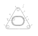
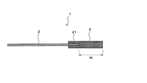
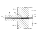
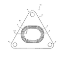
図1は、本発明に係るガスケットの一実施形態を示す平面図、図2は、図1中の(ii)−(ii)線に沿う拡大端面図、図3は、図1に示すガスケットの使用状態を図1中の(ii)−(ii)線と同じ部位に沿って切断した際の拡大断面図である。 FIG. 1 is a plan view showing an embodiment of the gasket according to the present invention, FIG. 2 is an enlarged end view taken along line (ii)-(ii) in FIG. 1, and FIG. 3 is a view of the gasket shown in FIG. It is an expanded sectional view at the time of cut | disconnecting a use condition along the same site | part as the (ii)-(ii) line | wire in FIG.
ガスケット1は、1枚の金属板2を有しており、この金属板2の中央部に、相手部材100、200の各流路101、201と連通して、シール対象となる流体を通過させる開口部3が設けられている。金属板2の角部には、相手部材100、200に亘ってボルトを挿通させるボルト孔4がそれぞれ設けられている。このガスケット1は、相手部材100、200の間に装着されることにより、該相手部材100、200の接合面間の隙間を密封し、流路101、201内の流体の漏洩を防止する。
The gasket 1 has a
金属板2は、ガスケット材料として一般に使用される例えばSUS材等の金属材によって、相手部材100、200の接合面の形状と同形状(本実施形態では三角形状)の平板状に形成されている。本実施形態に示す金属板2には、金属板2自体を屈曲することによって形成されるビードは設けられていない。金属板2の厚みは特に限定されないが、例えば0.15mm〜0.5mmとすることができる。
The
開口部3は、相手部材100、200に形成される流路101、201よりもやや大きく開口するように形成されている。そして、この開口部3に臨む金属板2の周縁部21に沿ってシール部材5が設けられている。
The
シール部材5は、金属板2よりも厚みが厚い黒鉛によって、開口部3を取り囲むように環状に形成されている。図2に示すように、シール部材5は、その外周側が金属板2の周縁部21を上下から挟み付けるようにして接着剤によって接着されている。シール部材5の内周側は、全周に亘って周縁部21から内方(開口部3の中心)に向けて所定の突出幅Wで突出している。これにより、金属板2の周縁部21は、内周端面を含めてシール部材5によって完全に被覆され、開口部3に露出していない。
The
シール部材5は、黒鉛をシート状に成形した黒鉛シートを、所定幅の環状に形成したものを用いることができる。シール部材5を構成する黒鉛は耐熱性に優れるため、このガスケット1によれば、金属板2の耐熱温度を超えるような高温の流体が開口部3を通過する場合であっても、十分に耐え得る良好な耐熱性を発揮する。黒鉛の種類は特に限定されないが、シール性の観点から膨張黒鉛を好ましく用いることができる。
As the sealing
シール部材5は金属板2よりも厚みが厚いため、図3に示すように、ガスケット1が相手部材100、200の間で締め付けられた際、その締め付け力をシール部材5に集中させることができ、シール部材5を効果的に圧縮させることができる。しかも、シール部材5が周縁部21から突出した部位には金属板2が存在しないため、締め付け時に厚み方向の全体を圧縮させることができる。これらにより、従来のように金属板の両面に黒鉛シートを設けたものに比べて、シール部材5の弾性復元性を良好に発揮させることができ、開口部3の周囲の密封性を高め、シール性を向上させることができる。
Since the
しかも、本実施形態に示すシール部材5は、その外周側で金属板2の周縁部21を上下から挟み付けるように設けられていることにより、ガスケット1の両面で相手部材100、200のそれぞれに対して上述した通りの良好なシール性を発揮することができる。
Moreover, the sealing
金属板2は、シール部材5によって周縁部21が完全に被覆されるため、開口部3を通過する流体の熱の影響を受けにくく、金属板2の熱劣化が起きにくい。しかも、シール部材5は、従来のようにビードの反力によって相手部材の接合面に密接する構成ではないため、高温環境下の使用においても、シール部材5を相手部材100、200の接合面の粗さや平面度に追従性させる効果が何ら損なわれることがなく、シール性を良好に確保することができる。
Since the
また、本発明に係るガスケット1において、このシール部材5が設けられる部位は、開口部3の周囲のみであるため、高価な黒鉛の使用量を必要最小限にとどめることができる。これにより、従来のように金属板の両面に黒鉛シートを設けるものに比べてコストアップを大幅に抑えることができる。
Further, in the gasket 1 according to the present invention, the portion where the
シール部材5の厚みは、金属板2よりも厚いものであれば特に限定されるものではないが、本発明の目的を達成できる範囲で適宜決定される。
The thickness of the
図2に示すように、金属板2の周縁部21からの突出幅Wは、相手部材100、200間で圧縮された際に内周側が流路101、201にはみ出さない程度に設定されるが、本発明の目的を達成できる範囲で適宜決定される。
As shown in FIG. 2, the protruding width W from the
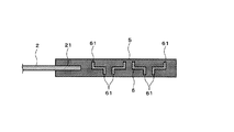
シール部材5の内部、具体的には周縁部21よりも内方に突出した部位の内部には、図4に示すように、フック形金属板6を設けることも好ましい。フック形金属板6は、金属薄板に複数のツメを切り立ててフック61を形成したものである。このフック61をシール部材5を構成する黒鉛に食い込ませることにより、高温環境下におけるクリープを防止して長期に亘るシール性の維持を図ることができる。
As shown in FIG. 4, it is also preferable to provide a hook-shaped metal plate 6 inside the
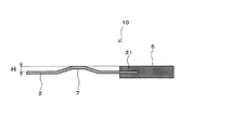
図5は、本発明に係るガスケットの他の実施形態を示す平面図、図6は、図5中の(vi)−(vi)線に沿う拡大端面図である。図1、図2と同一符号の部位は同一構成の部位を示しているため、それらの詳細な説明は上記記載を援用し、ここでは省略する。 FIG. 5 is a plan view showing another embodiment of the gasket according to the present invention, and FIG. 6 is an enlarged end view taken along line (vi)-(vi) in FIG. 1 and 2 indicate parts having the same configuration, and the detailed description thereof uses the above description and is omitted here.
本実施形態に示すガスケット10は、金属板2にビード7を設けたものである。ビード7は、金属板2をプレス成形により屈曲することによって形成されたものであり、シール部材5よりも外側に、該シール部材5から離れて配置され、該シール部材5を取り囲むように環状に形成されている。図6に示すビード7はフルビードとされているが、特に制限はなく、例えばハーフビードであってもよい。
The
このビード7は、ガスケット10が相手部材100、200間で締め付けられた際、シール部材5よりも外側で面圧を発生させる。これにより、シール部材5に対する補助的なシール機能を発揮し、ガスケット10のシール性をさらに向上させることができる。上述したように、金属板2はシール部材5の存在によって、開口部3を通過する流体の熱の影響を受けにくいため、熱劣化によるビード7のヘタリは起きにくいが、たとえ高温環境下での長期使用による熱の影響によってビード7にヘタリが発生することがあっても、ビード7はシール部材5の外側に離れて配置されているため、シール部材5のシール性に何ら影響を及ぼすことはない。
The
また、このビード7は、開口部3の形状を保持するいわゆる補強リブとしての機能をも発揮するため、金属板2の歪みを抑制してシール部材5の厚み方向の歪みを抑える効果が得られる。従って、このガスケット10によれば、相手部材100、200の間で締め付けられた際、シール部材5を全周に亘って均一に圧縮することができ、開口部3の全周に亘って一層良好なシール性を発揮することができる。
Moreover, since this
ビード7の高さHは、図6に示すように、金属板2の表面からのシール部材5の高さ以下となるように設定されることが好ましい。これにより、ビード7がその内側のシール部材5の圧縮に与える影響を極力抑えることができる。
As shown in FIG. 6, the height H of the
なお、このガスケット10のシール部材5の内部にも、図4と同様にフック形金属板6を設けてもよいことはもちろんである。
Needless to say, the hook-shaped metal plate 6 may be provided inside the
以上説明したガスケット1、10は、相手部材の接合面間に装着されることにより、液体やガス等の流体をシールする目的で広く使用することができる。特に、シール部材5が高い耐熱性を発揮することから、自動車等のエンジンの排気系の部品同士の接合部において、高温の排気ガスをシールするために好適に使用することができる。
The
1、10:ガスケット
2:金属板
21:周縁部
3:開口部
4:ボルト孔
5:シール部材
6:フック形金属板
61:フック
7:ビード
100、200:相手部材
101、201:流路
DESCRIPTION OF SYMBOLS 1, 10: Gasket 2: Metal plate 21: Peripheral part 3: Opening part 4: Bolt hole 5: Seal member 6: Hook-shaped metal plate 61: Hook 7:
Claims (5)
The gasket according to claim 4, wherein a height of the bead is set to be equal to or less than a height of the seal member from a surface of the metal plate.
Priority Applications (1)
| Application Number | Priority Date | Filing Date | Title |
|---|---|---|---|
| JP2016079157A JP2017190801A (en) | 2016-04-11 | 2016-04-11 | gasket |
Applications Claiming Priority (1)
| Application Number | Priority Date | Filing Date | Title |
|---|---|---|---|
| JP2016079157A JP2017190801A (en) | 2016-04-11 | 2016-04-11 | gasket |
Publications (1)
| Publication Number | Publication Date |
|---|---|
| JP2017190801A true JP2017190801A (en) | 2017-10-19 |
Family
ID=60084714
Family Applications (1)
| Application Number | Title | Priority Date | Filing Date |
|---|---|---|---|
| JP2016079157A Pending JP2017190801A (en) | 2016-04-11 | 2016-04-11 | gasket |
Country Status (1)
| Country | Link |
|---|---|
| JP (1) | JP2017190801A (en) |
Cited By (1)
| Publication number | Priority date | Publication date | Assignee | Title |
|---|---|---|---|---|
| CN110406016A (en) * | 2019-09-03 | 2019-11-05 | 攸佟国际贸易(上海)有限公司 | An electromagnetic welding sealing and fixing gasket |
-
2016
- 2016-04-11 JP JP2016079157A patent/JP2017190801A/en active Pending
Cited By (1)
| Publication number | Priority date | Publication date | Assignee | Title |
|---|---|---|---|---|
| CN110406016A (en) * | 2019-09-03 | 2019-11-05 | 攸佟国际贸易(上海)有限公司 | An electromagnetic welding sealing and fixing gasket |
Similar Documents
| Publication | Publication Date | Title |
|---|---|---|
| JP5780401B2 (en) | Plate-integrated gasket | |
| JP5599787B2 (en) | Comb double-sided coated gasket for sealing removable flange joints | |
| JP4324607B2 (en) | Non-asbestos gasket | |
| JP2008248952A (en) | Metal gasket | |
| CN101408247A (en) | Metal gasket | |
| KR101506189B1 (en) | An insulated gasket for high temperature and pressure having sealing pad | |
| RU2395740C1 (en) | Sealing metal ring and detachable flanged sealing device (versions) | |
| JP4361096B2 (en) | Metal gasket | |
| JP2017190801A (en) | gasket | |
| JP4855356B2 (en) | Sealed structure | |
| CN101802464A (en) | Cylinder head gasket | |
| JP4110256B2 (en) | Metal gasket | |
| US20060197288A1 (en) | Metal laminate cylinder head gasket | |
| CN105026808B (en) | Heat-resistant liner | |
| JP4541399B2 (en) | Metal gasket | |
| KR20170000076U (en) | Multi kammprofile gasket | |
| JP2008223581A (en) | Metal gasket | |
| JP2016148408A (en) | gasket | |
| JP2018179118A (en) | Gasket | |
| JP2013040679A (en) | Corrosion resistant composite seal structure | |
| WO2018123214A1 (en) | Metal gasket | |
| JP2018159463A (en) | Pipe connection mechanism | |
| JP2015200366A (en) | Zygote | |
| JP2025003090A (en) | Gasket and manufacturing method thereof | |
| KR20170136347A (en) | Gasket for warming-up catalytic converter and turbocharger |
Legal Events
| Date | Code | Title | Description |
|---|---|---|---|
| RD03 | Notification of appointment of power of attorney |
Free format text: JAPANESE INTERMEDIATE CODE: A7423 Effective date: 20181116 |
|
| A621 | Written request for application examination |
Free format text: JAPANESE INTERMEDIATE CODE: A621 Effective date: 20190320 |
|
| A977 | Report on retrieval |
Free format text: JAPANESE INTERMEDIATE CODE: A971007 Effective date: 20200309 |
|
| A131 | Notification of reasons for refusal |
Free format text: JAPANESE INTERMEDIATE CODE: A131 Effective date: 20200316 |
|
| A02 | Decision of refusal |
Free format text: JAPANESE INTERMEDIATE CODE: A02 Effective date: 20200915 |