JP2017190786A - Sealing device - Google Patents

Sealing device Download PDF

Info

Publication number
JP2017190786A
JP2017190786A JP2016078716A JP2016078716A JP2017190786A JP 2017190786 A JP2017190786 A JP 2017190786A JP 2016078716 A JP2016078716 A JP 2016078716A JP 2016078716 A JP2016078716 A JP 2016078716A JP 2017190786 A JP2017190786 A JP 2017190786A
Authority
JP
Japan
Prior art keywords
sleeve
seal
inner ring
radial lip
torque
Prior art date
Legal status (The legal status is an assumption and is not a legal conclusion. Google has not performed a legal analysis and makes no representation as to the accuracy of the status listed.)
Pending
Application number
JP2016078716A
Other languages
Japanese (ja)
Inventor
和生 濱田
Kazuo Hamada
和生 濱田
Current Assignee (The listed assignees may be inaccurate. Google has not performed a legal analysis and makes no representation or warranty as to the accuracy of the list.)
JTEKT Corp
Original Assignee
JTEKT Corp
Priority date (The priority date is an assumption and is not a legal conclusion. Google has not performed a legal analysis and makes no representation as to the accuracy of the date listed.)
Filing date
Publication date
Application filed by JTEKT Corp filed Critical JTEKT Corp
Priority to JP2016078716A priority Critical patent/JP2017190786A/en
Publication of JP2017190786A publication Critical patent/JP2017190786A/en
Pending legal-status Critical Current

Links

Images

Landscapes

  • Sealing Devices (AREA)
  • Rolling Contact Bearings (AREA)
  • Sealing With Elastic Sealing Lips (AREA)

Abstract

【課題】内輪が高速で回転するときに、シール摺接部の発熱を抑制し、耐久性を向上させた密封装置を提供する。【解決手段】密封装置10が、第1ラジアルリップ17を備えた第1シール11と、第2ラジアルリップ22を備えた第2シール12と、軸受30によって内輪及び外輪と同軸で回転自在に支持されたスリーブ14と、を備えており、第1シール11は、外輪に対して回転不能に固定されるとともに第1ラジアルリップ17がスリーブ14と接触しており、第2シール12は、スリーブ14に対して回転不能に固定されるとともに第2ラジアルリップ22が内輪と径方向に接触しており、内輪に対するスリーブ14の回転トルクが、外輪に対するスリーブ14の回転トルクと同等である。【選択図】図1Provided is a sealing device in which heat generation at a seal sliding contact portion is suppressed and durability is improved when an inner ring rotates at a high speed. A sealing device 10 is supported by a first seal 11 having a first radial lip 17, a second seal 12 having a second radial lip 22, and a bearing 30 so as to be rotatable coaxially with an inner ring and an outer ring. The first seal 11 is fixed to the outer ring so as not to rotate, the first radial lip 17 is in contact with the sleeve 14, and the second seal 12 is provided with the sleeve 14. And the second radial lip 22 is in radial contact with the inner ring, and the rotational torque of the sleeve 14 relative to the inner ring is equal to the rotational torque of the sleeve 14 relative to the outer ring. [Selection] Figure 1

Description

本発明は、シールリップの摺動速度が高い用途に使用される密封装置であって、特に鉄鋼圧延機用ワークロールを支持する軸受装置に好適に使用される密封装置に関する。   The present invention relates to a sealing device that is used for applications in which a sliding speed of a seal lip is high, and particularly relates to a sealing device that is preferably used for a bearing device that supports a work roll for a steel rolling mill.

従来より、鉄鋼圧延機用ワークロールを支持する軸受装置では、密封装置を装着したものが知られている(例えば、特許文献1)。   2. Description of the Related Art Conventionally, a bearing device that supports a work roll for a steel rolling mill is known in which a sealing device is mounted (for example, Patent Document 1).

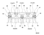
図2は、鉄鋼圧延機用ワークロールを支持する従来の軸受装置80を示す断面図である。軸受装置80は、4列の円すいころ軸受を組合わせた構成となっており、外輪81が図示しないハウジングの内周に固定され、内輪83が図示しないワークロール軸端の外周に嵌め合わされている。
軸受装置80には、圧延ロールを冷却する冷却水や圧延油等が多量に掛かっている。これらが軸受内部に浸入すると、グリースが劣化し、軸受寿命を大幅に短縮させる。軸受装置80が損傷すると圧延ロールの振動が大きくなり、圧延精度が劣化するので、冷却水や圧延油等が軸受内部に浸入するのを防止する必要がある。
FIG. 2 is a cross-sectional view showing a conventional bearing device 80 that supports a work roll for a steel rolling mill. The bearing device 80 has a configuration in which four rows of tapered roller bearings are combined. The outer ring 81 is fixed to the inner periphery of a housing (not shown), and the inner ring 83 is fitted to the outer periphery of a work roll shaft end (not shown). .
A large amount of cooling water, rolling oil, or the like is applied to the bearing device 80 to cool the rolling roll. If they enter the bearing, the grease will deteriorate and the bearing life will be greatly shortened. If the bearing device 80 is damaged, the vibration of the rolling roll increases and the rolling accuracy deteriorates. Therefore, it is necessary to prevent cooling water, rolling oil, and the like from entering the bearing.

外輪81は、単列の外輪81a、複列の外輪81b、単列の外輪81cが、軸方向に順に配置されており、互いに隣接する外輪81の間には間座82が組込まれている。間座82には、径方向に貫通する穴が設けられており、穴を通してグリースが軸受内部に給油されている。
内輪83は、複列の内輪83a,83bが軸方向に並べて配置されている。内輪83間の突当部には内シール84が装着されており、突当部からのグリースの流出を防止している。また、各内輪83には、略円筒形状のシール摺接部85が一体に形成されている。
In the outer ring 81, a single-row outer ring 81a, a double-row outer ring 81b, and a single-row outer ring 81c are arranged in this order in the axial direction, and a spacer 82 is incorporated between the adjacent outer rings 81. The spacer 82 is provided with a hole penetrating in the radial direction, and grease is supplied into the bearing through the hole.
In the inner ring 83, double-row inner rings 83a and 83b are arranged side by side in the axial direction. An inner seal 84 is attached to the abutting portion between the inner rings 83 to prevent the grease from flowing out from the abutting portion. Each inner ring 83 is integrally formed with a substantially cylindrical seal sliding contact portion 85.

従来の軸受装置80では、軸受装置80の軸方向両端部にプレート87が固定されており、密封装置90は、プレート87の内周に固定されている。図3は、従来の密封装置90の形態を説明するための要部拡大図である。
密封装置90は、軸方向断面がL字状の金属製の芯金91と、ゴム材で芯金91と一体に成形されたラジアルリップ92及びグリースリップ93を備えている。ラジアルリップ92は、芯金91の内周端部から軸方向外向きに突出しており、内輪83のシール摺接部85の外周面と接触している。グリースリップ93は、芯金91の内周端部から軸方向内向きに突出している。グリースリップ93は、シール摺接部85の外周面とわずかなすきまをもって対向している。
In the conventional bearing device 80, the plates 87 are fixed to both axial ends of the bearing device 80, and the sealing device 90 is fixed to the inner periphery of the plate 87. FIG. 3 is an enlarged view of a main part for explaining the form of the conventional sealing device 90.
The sealing device 90 includes a metal cored bar 91 having an L-shaped axial cross section, and a radial lip 92 and a grease lip 93 formed integrally with the cored bar 91 with a rubber material. The radial lip 92 protrudes outward in the axial direction from the inner peripheral end portion of the cored bar 91 and is in contact with the outer peripheral surface of the seal sliding contact portion 85 of the inner ring 83. The grease lip 93 protrudes inward in the axial direction from the inner peripheral end of the cored bar 91. The grease lip 93 faces the outer peripheral surface of the seal sliding contact portion 85 with a slight clearance.

こうして、密封装置90は、ラジアルリップ92によって冷却水や圧延油等の浸入を防止するとともに、内部グリースの漏出を防止している。また、グリースリップ93を設けることによって、リップ間にグリースを保持して、ラジアルリップ92の摺接部の潤滑を確保している。   Thus, the sealing device 90 prevents the cooling water and rolling oil from entering by the radial lip 92 and prevents leakage of internal grease. Further, by providing the grease lip 93, the grease is held between the lips to ensure lubrication of the sliding contact portion of the radial lip 92.

特開2001−20962号公報JP 2001-20962 A

近年、圧延鋼板の生産性を向上するために、圧延速度が高くなっている。このため、内輪83の回転速度が高くなっており、ラジアルリップ92と内輪83との摺動速度は毎分2800m程度になっている。
摺動速度が高くなると、ラジアルリップ92の摺接部が発熱してゴム材が劣化し、ラジアルリップ92の先端に亀裂やクラックが発生する。この結果、冷却水が軸受内部に浸入したり、軸受内部に封入したグリースが漏れ出たりすることによってころの転動面の潤滑状態が劣化して、軸受装置80が焼き付くという問題が生じている。
In recent years, the rolling speed has been increased in order to improve the productivity of rolled steel sheets. For this reason, the rotation speed of the inner ring 83 is high, and the sliding speed between the radial lip 92 and the inner ring 83 is about 2800 m / min.
When the sliding speed increases, the sliding contact portion of the radial lip 92 generates heat, the rubber material deteriorates, and a crack or a crack occurs at the tip of the radial lip 92. As a result, there is a problem that the bearing device 80 is seized due to deterioration of the lubrication state of the rolling surface of the roller due to the coolant entering the inside of the bearing or the grease sealed in the inside of the bearing leaking out. .

本発明は、内輪が高速で回転するときに、シール摺接部の発熱を抑制し、耐久性を向上させた密封装置を提供することを目的としている。   An object of the present invention is to provide a sealing device that suppresses heat generation at a seal sliding contact portion and improves durability when an inner ring rotates at a high speed.

本発明の一形態は、回転体である内輪および回転しないハウジングに固定された外輪と、これら内外輪間に介在させた複数の転動体とを備えた軸受装置における、前記内外輪間の環状空間を密封する密封装置が、金属製の第1芯金及び弾性体からなる第1ラジアルリップを備えた第1シールと、金属製の第2芯金及び弾性体からなる第2ラジアルリップを備えた第2シールと、軸受によって前記内輪及び前記外輪と同軸で回転自在に支持されたスリーブと、を備えており、前記第1シールは、前記第1芯金が前記外輪に対して回転不能に固定されるとともに前記第1ラジアルリップが前記スリーブと接触しており、前記第2シールは、前記第2芯金が前記スリーブに対して回転不能に固定されるとともに前記第2ラジアルリップが前記内輪と径方向に接触しており、前記内輪に対する前記スリーブの回転トルクが、前記外輪に対する前記スリーブの回転トルクと同等であることを特徴としている。   One aspect of the present invention is an annular space between the inner and outer rings in a bearing device including an inner ring as a rotating body and an outer ring fixed to a non-rotating housing, and a plurality of rolling elements interposed between the inner and outer rings. The first sealing device having a first radial lip made of a metal first metal core and an elastic body, and the second radial lip made of a second metal metal core and an elastic body. A second seal and a sleeve rotatably supported coaxially with the inner ring and the outer ring by a bearing, and the first seal is fixed so that the first core metal cannot rotate with respect to the outer ring. The first radial lip is in contact with the sleeve, and the second seal is fixed to the sleeve so that the second core metal cannot rotate with respect to the sleeve, and the second radial lip is connected to the inner ring. Is in contact with the direction, the rotational torque of the sleeve relative to the inner ring, is characterized in that it is equal to the rotation torque of the sleeve relative to the outer ring.

内輪が高速で回転した場合であっても、シール摺接部の摺動速度を低減できるので、シール摺接部の発熱を抑制し、耐久性を向上させた密封装置を提供することができる。   Even when the inner ring rotates at a high speed, the sliding speed of the seal sliding contact portion can be reduced. Therefore, it is possible to provide a sealing device that suppresses heat generation of the seal sliding contact portion and improves durability.

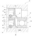
本発明の一実施形態である密封装置の軸方向断面図である。It is an axial sectional view of the sealing device which is one embodiment of the present invention. 従来の密封装置が組込まれた鉄鋼圧延機用ワークロール支持軸受の断面図である。It is sectional drawing of the work roll support bearing for steel mills in which the conventional sealing device was incorporated. 従来の密封装置の軸方向断面図である。It is an axial sectional view of a conventional sealing device.

図を用いて本発明の実施の形態を詳細に説明する。
図1は、本発明の一実施形態(以下「本実施形態」)である密封装置10の軸方向断面図である。密封装置10は、鉄鋼圧延機用ワークロールを回転自在に支持する軸受装置40に組付けられている。
軸受装置40は、密封装置10以外の構成については、図2に示した従来の軸受装置80と同様の構成である。このため、従来の軸受装置80と共通の構成については説明を簡単にして、密封装置10の構造と作用について詳細に説明する。なお、密封装置10以外の構成については、従来の軸受装置80と同一の符号を付して説明する。
Embodiments of the present invention will be described in detail with reference to the drawings.
FIG. 1 is an axial sectional view of a sealing device 10 according to an embodiment of the present invention (hereinafter referred to as “this embodiment”). The sealing device 10 is assembled to a bearing device 40 that rotatably supports a work roll for a steel rolling mill.
The bearing device 40 has the same configuration as that of the conventional bearing device 80 shown in FIG. Therefore, the structure common to the conventional bearing device 80 will be briefly described, and the structure and operation of the sealing device 10 will be described in detail. In addition, about structures other than the sealing device 10, the code | symbol same as the conventional bearing apparatus 80 is attached | subjected and demonstrated.

軸受装置40は、4列の円すいころ軸受を組合わせた構成である。外輪81は、単列の外輪81aと複列の外輪81bと単列の外輪81cとが軸方向に順に配置され、隣接する外輪81の間にそれぞれ円環状の間座82が組込まれた構成となっている。このように組合わされた外輪81の軸方向両外側に、円環状のプレート87が組付けられている。   The bearing device 40 has a configuration in which four rows of tapered roller bearings are combined. The outer ring 81 has a configuration in which a single row outer ring 81a, a double row outer ring 81b, and a single row outer ring 81c are sequentially arranged in the axial direction, and an annular spacer 82 is incorporated between adjacent outer rings 81, respectively. It has become. An annular plate 87 is assembled to both outer sides in the axial direction of the outer ring 81 combined in this way.

内輪83は、複列の内輪83a,83bを軸方向に並べて配置した構成である。内輪83aと内輪83bとが軸方向に当接している部分では、当接部からグリースの流出を防ぐために内シール84が組込まれている。各内輪83a,83bの軸方向外側に、略円筒形状のシール摺接部85が一体に形成されている。シール摺接部85は、プレート87と軸方向のほぼ同じ位置に設けられている。   The inner ring 83 has a structure in which double-row inner rings 83a and 83b are arranged in the axial direction. In a portion where the inner ring 83a and the inner ring 83b are in contact with each other in the axial direction, an inner seal 84 is incorporated to prevent the grease from flowing out from the contact portion. A substantially cylindrical seal sliding contact portion 85 is integrally formed on the outer side in the axial direction of each of the inner rings 83a and 83b. The seal sliding contact portion 85 is provided at substantially the same position in the axial direction as the plate 87.

各外輪81の内周には、テーパ面の外側軌道面が形成されており、各内輪83の外周にはテーパ面の内側軌道面が形成されている。外側軌道面と内側軌道面との間には、それぞれ複数の円すいころ88が組込まれている。円すいころ88は保持器89によって周方向に等しい間隔で保持されている。   A tapered outer raceway surface is formed on the inner periphery of each outer ring 81, and a tapered inner track surface is formed on the outer periphery of each inner ring 83. A plurality of tapered rollers 88 are respectively incorporated between the outer raceway surface and the inner raceway surface. The tapered rollers 88 are held at equal intervals in the circumferential direction by a cage 89.

プレート87の内周とシール摺接部85の外周との間に密封装置10が組付けられていて、内輪83と外輪81とで径方向に挟まれた環状空間25を密封している。密封装置10の構成については後述する。   The sealing device 10 is assembled between the inner periphery of the plate 87 and the outer periphery of the seal sliding contact portion 85 to seal the annular space 25 sandwiched between the inner ring 83 and the outer ring 81 in the radial direction. The configuration of the sealing device 10 will be described later.

鉄鋼圧延機用ワークロールでは、軸受装置40は、外輪81及びプレート87が図示しないハウジングの内周に嵌め合わされており、内輪83が図示しないワークロールの軸端の外周に嵌め合わされている。プレート87の外周にはOリング86が装着されており、ハウジングとの嵌合面からグリースが流出するのを防いでいる。   In the work roll for a steel rolling mill, in the bearing device 40, the outer ring 81 and the plate 87 are fitted to the inner circumference of the housing (not shown), and the inner ring 83 is fitted to the outer circumference of the shaft end of the work roll (not shown). An O-ring 86 is mounted on the outer periphery of the plate 87 to prevent the grease from flowing out from the fitting surface with the housing.

次に、図1によって、密封装置10について説明する。
密封装置10は、同軸に組合わされた第1シール11及び第2シール12と、周方向に一様な肉厚で円筒形状に形成されたスリーブ14と、スリーブ14を回転自在に支持する転がり軸受としての深溝玉軸受30とを備えている。
Next, the sealing device 10 will be described with reference to FIG.
The sealing device 10 includes a first seal 11 and a second seal 12 that are coaxially combined, a sleeve 14 that is formed in a cylindrical shape with a uniform thickness in the circumferential direction, and a rolling bearing that rotatably supports the sleeve 14. As a deep groove ball bearing 30.

スリーブ14は、高炭素鋼を焼入れ硬化処理した後、外径面及び内径面が研削加工によって精密な円筒形状に仕上げられている。スリーブ14の内周には、深溝玉軸受30の外レース31の外径が締り嵌めの状態で嵌め合わされている。深溝玉軸受30の内レース32は、その内径が内輪83のシール摺接部85の外周面に締り嵌めの状態で嵌め合わされている。こうして、スリーブ14は、内輪83に対して回転自在である。   After the high-carbon steel is quenched and hardened, the sleeve 14 has an outer diameter surface and an inner diameter surface finished to a precise cylindrical shape by grinding. The outer diameter of the outer race 31 of the deep groove ball bearing 30 is fitted to the inner periphery of the sleeve 14 in an interference fit state. The inner race 32 of the deep groove ball bearing 30 is fitted into the outer peripheral surface of the seal sliding contact portion 85 of the inner ring 83 in an interference fit state. Thus, the sleeve 14 is rotatable with respect to the inner ring 83.

第1シール11は、金属製の第1芯金16と、第1芯金16に一体に成形された第1ラジアルリップ17及び第1グリースリップ18と、第1ばね19とで構成されている。
第1芯金16は、環状で、SPCCなどの冷間圧延鋼板をプレス加工することによって形成されている。第1芯金16は、軸方向断面がL字状であり、軸と同軸の円筒形状である第1円筒部16aと、第1円筒部16aの軸方向一端から径方向内方に延在する第1フランジ部16bとが一体に形成されている。
The first seal 11 includes a metal first metal core 16, a first radial lip 17 and a first grease lip 18 formed integrally with the first metal core 16, and a first spring 19. .
The first cored bar 16 is annular and is formed by pressing a cold rolled steel plate such as SPCC. The first core bar 16 has an L-shaped axial cross section, and extends inward in the radial direction from one axial end of the first cylindrical portion 16a and a first cylindrical portion 16a having a cylindrical shape coaxial with the shaft. The first flange portion 16b is integrally formed.

第1ラジアルリップ17及び第1グリースリップ18は、ニトリルゴムやアクリルゴムなどの弾性体で形成されている。第1ラジアルリップ17は、第1フランジ部16bの径方向内方端部から第1円筒部16aと同じ向きに略軸方向に延在しており、第1グリースリップ18は、第1ラジアルリップ17と同じく第1フランジ部16bの径方向内方端部から第1ラジアルリップ17とは反対向きに略軸方向に延在している。第1ラジアルリップ17及び第1グリースリップ18を形成している弾性体は、さらに、第1円筒部16aの外周と第1フランジ部16bの軸方向の一方の側面を覆うように形成されている。
第1ラジアルリップ17及び第1グリースリップ18は、第1芯金16を上記弾性体にモールドした状態で、高温の金型で加硫成型することによって形成されている。
The first radial lip 17 and the first grease lip 18 are formed of an elastic body such as nitrile rubber or acrylic rubber. The first radial lip 17 extends in the substantially axial direction from the radially inner end of the first flange portion 16b in the same direction as the first cylindrical portion 16a, and the first grease lip 18 is the first radial lip. As in FIG. 17, the first flange 16 b extends in the substantially axial direction from the radially inner end of the first flange 16 b in the direction opposite to the first radial lip 17. The elastic body forming the first radial lip 17 and the first grease lip 18 is further formed so as to cover the outer periphery of the first cylindrical portion 16a and one side surface of the first flange portion 16b in the axial direction. .
The first radial lip 17 and the first grease lip 18 are formed by vulcanization molding with a high-temperature mold in a state where the first core 16 is molded on the elastic body.

第1ラジアルリップ17の外周には、環状の第1ばね19が装着されている。第1ばね19は、周方向に弾性的に伸びることができる。   An annular first spring 19 is attached to the outer periphery of the first radial lip 17. The first spring 19 can elastically extend in the circumferential direction.

第1シール11は、その外周がプレート87の内周に締り嵌めの状態で嵌め合わされている。プレート87の内周と第1円筒部16aの外周との間では、弾性体が径方向に圧縮された状態で組付けられている。これにより、プレート87と第1シール11の嵌合部からのグリースの流出が防止されている。   The outer periphery of the first seal 11 is fitted into the inner periphery of the plate 87 in an interference fit state. Between the inner periphery of the plate 87 and the outer periphery of the first cylindrical portion 16a, the elastic body is assembled in a state compressed in the radial direction. Thereby, the outflow of grease from the fitting portion between the plate 87 and the first seal 11 is prevented.

第1ラジアルリップ17の内周は、スリーブ14の外周面と全周にわたって接触している。第1シール11を装着する前の状態では、第1ラジアルリップ17の内径寸法は、スリーブ14の外径寸法より小さい。この寸法差(直径)の1/2をラジアルリップのしめしろδ1という。図1では、第1ラジアルリップ17がしめしろδ1を有する状態を示すために、スリーブ14と重なった形態で示している。第1ラジアルリップ17及び第1ばね19は径方向に弾性を有しているので、実際に組付けたときには、このしめしろδ1の分だけ第1ラジアルリップ17の先端部及び第1ばね19が拡径している。このとき、第1ラジアルリップ17の内周はスリーブ14の外周に所定の大きさの力で径方向に接触している。   The inner periphery of the first radial lip 17 is in contact with the outer peripheral surface of the sleeve 14 over the entire periphery. Before the first seal 11 is attached, the inner diameter dimension of the first radial lip 17 is smaller than the outer diameter dimension of the sleeve 14. 1/2 of this dimensional difference (diameter) is called radial lip interference δ1. In FIG. 1, in order to show a state in which the first radial lip 17 has the interference δ1, the first radial lip 17 is shown in a form overlapping with the sleeve. Since the first radial lip 17 and the first spring 19 have elasticity in the radial direction, when actually assembled, the tip end portion of the first radial lip 17 and the first spring 19 are equivalent to this interference δ1. The diameter is expanded. At this time, the inner periphery of the first radial lip 17 is in contact with the outer periphery of the sleeve 14 in the radial direction with a predetermined amount of force.

第1グリースリップ18の内径寸法はスリーブ14の外径寸法よりわずかに大きい。このため、内輪83の回転中に第1グリースリップ18とスリーブ14とが接触しないので、第1グリースリップ18が滑り摩擦によって発熱することがない。第1シール11を組付けるときには、第1ラジアルリップ17と第1グリースリップ18とで軸方向に挟まれた空間にグリースが塗布されている。このグリースによって、第1ラジアルリップ17とスリーブ14との摺接部が潤滑されている。   The inner diameter of the first grease lip 18 is slightly larger than the outer diameter of the sleeve 14. For this reason, the first grease lip 18 and the sleeve 14 do not come into contact with each other during the rotation of the inner ring 83, so that the first grease lip 18 does not generate heat due to sliding friction. When the first seal 11 is assembled, grease is applied to a space sandwiched between the first radial lip 17 and the first grease lip 18 in the axial direction. This grease lubricates the sliding contact portion between the first radial lip 17 and the sleeve 14.

第2シール12は、深溝玉軸受30で回転自在に支持されたスリーブ14の内周に、締り嵌めの状態で嵌め合わされている。   The second seal 12 is fitted into the inner periphery of the sleeve 14 rotatably supported by the deep groove ball bearing 30 in an interference fit state.

第2シール12は、金属製の第2芯金21と、第2芯金21に一体に成形された第2ラジアルリップ22及び第2グリースリップ23と、第2ばね24とで構成されている。第2シール12は、第1シール11と軸方向断面の形態がほぼ同一であるので、共通する形態については簡単に説明する。また、各構成の材質及び製造方法は、第1シール11における材質及び製造方法と同様であるので、説明を省略する。   The second seal 12 includes a metal second metal core 21, a second radial lip 22 and a second grease lip 23 that are integrally formed with the second metal core 21, and a second spring 24. . Since the second seal 12 has substantially the same shape as the first seal 11 in the axial cross section, the common form will be briefly described. Moreover, since the material and manufacturing method of each structure are the same as the material and manufacturing method in the 1st seal | sticker 11, description is abbreviate | omitted.

第2芯金21は、軸方向断面がL字状であり、軸と同軸の円筒形状である第2円筒部21aと、第2円筒部21aの軸方向一端から径方向内方に延在する第2フランジ部21bとが一体に形成されている。   The second metal core 21 has an L-shaped axial cross section, and extends inward in the radial direction from the second cylindrical portion 21a having a cylindrical shape coaxial with the shaft and one axial end of the second cylindrical portion 21a. The second flange portion 21b is integrally formed.

第2ラジアルリップ22は、第2フランジ部21bの径方向内方端部から第2円筒部21aと同じ向きに略軸方向に延在しており、第2グリースリップ23は、第2ラジアルリップ22と同じく第2フランジ部21bの径方向内方端部から第2ラジアルリップ22とは反対向きに略軸方向に延在している。第2ラジアルリップ22及び第2グリースリップ23を形成している弾性体は、さらに、第2円筒部21aの外周と第2フランジ部21bの軸方向の一方の側面を覆うように形成されている。   The second radial lip 22 extends in the substantially axial direction from the radially inner end of the second flange portion 21b in the same direction as the second cylindrical portion 21a, and the second grease lip 23 is the second radial lip As in FIG. 22, the second flange 21 b extends in the substantially axial direction from the radially inner end of the second flange 21 b in the opposite direction to the second radial lip 22. The elastic body forming the second radial lip 22 and the second grease lip 23 is further formed so as to cover the outer periphery of the second cylindrical portion 21a and one side surface of the second flange portion 21b in the axial direction. .

第2ラジアルリップ22の外周には、環状の第2ばね24が装着されている。第2ばね24は、周方向に弾性的に伸びることができる。   An annular second spring 24 is mounted on the outer periphery of the second radial lip 22. The second spring 24 can elastically extend in the circumferential direction.

第2シール12は、その外周がスリーブ14の内周に締り嵌めの状態で嵌め合わされている。スリーブ14の内周と第2円筒部21aの外周との間では、弾性体が径方向に圧縮された状態で組付けられている。これにより、スリーブ14と第2シール12の嵌合部からのグリースの流出が防止されている。   The outer periphery of the second seal 12 is fitted into the inner periphery of the sleeve 14 in an interference fit state. Between the inner periphery of the sleeve 14 and the outer periphery of the second cylindrical portion 21a, the elastic body is assembled in a state compressed in the radial direction. Thereby, the outflow of grease from the fitting portion between the sleeve 14 and the second seal 12 is prevented.

第2ラジアルリップ22の内周は、シール摺接部85の外周面と全周にわたって接触している。第2シール12を装着する前の状態では、第2ラジアルリップ22の内径寸法はシール摺接部85の外径寸法より小さい。図1では、第2ラジアルリップ22がしめしろδ2を有する状態を示すために、シール摺接部85と重なった形態で示している。実際に組付けたときには、このしめしろδ2の分だけ第2ラジアルリップ22及び第2ばね24が拡径しており、第2ラジアルリップ22の内周はシール摺接部85の外周に所定の大きさの力で径方向に接触している。   The inner periphery of the second radial lip 22 is in contact with the outer peripheral surface of the seal sliding contact portion 85 over the entire periphery. In a state before the second seal 12 is mounted, the inner diameter dimension of the second radial lip 22 is smaller than the outer diameter dimension of the seal sliding contact portion 85. In FIG. 1, in order to show a state in which the second radial lip 22 has the interference δ2, the second radial lip 22 is shown in a form overlapping the seal sliding contact portion 85. When actually assembled, the diameter of the second radial lip 22 and the second spring 24 is increased by the amount of the interference δ2, and the inner periphery of the second radial lip 22 is set to a predetermined distance on the outer periphery of the seal sliding contact portion 85. It is in radial contact with a large force.

第2グリースリップ23の内径寸法はシール摺接部85の外径寸法よりわずかに大きい。このため、第2グリースリップ23はシール摺接部85の外周面と接触しないので、回転中にシール摺接部85との間で発熱することがない。第2シール12を組付けるときには、第2ラジアルリップ22と第2グリースリップ23とで軸方向に挟まれた空間にグリースを塗布している。このグリースによって、第2ラジアルリップ22とシール摺接部85外周面との摺接部が潤滑されている。   The inner diameter dimension of the second grease lip 23 is slightly larger than the outer diameter dimension of the seal sliding contact portion 85. For this reason, since the second grease lip 23 does not come into contact with the outer peripheral surface of the seal sliding contact portion 85, heat is not generated between the second grease lip 23 and the seal sliding contact portion 85 during rotation. When the second seal 12 is assembled, grease is applied to a space sandwiched between the second radial lip 22 and the second grease lip 23 in the axial direction. This grease lubricates the sliding contact portion between the second radial lip 22 and the outer peripheral surface of the seal sliding contact portion 85.

次に、図1を参照しつつ、本実施形態における密封装置10の作用を説明する。
以下の説明では、第1ラジアルリップ17及び第2ラジアルリップ22が、それぞれスリーブ14及びシール摺接部85の外周面を摺動するときのすべり抵抗を、それぞれ第1シールトルクT1、第2シールトルクT2とする。
Next, the operation of the sealing device 10 in this embodiment will be described with reference to FIG.
In the following description, the sliding resistance when the first radial lip 17 and the second radial lip 22 slide on the outer peripheral surface of the sleeve 14 and the seal sliding contact portion 85 respectively, and the first seal torque T 1 , and seal torque T 2.

本実施形態では、スリーブ14は、深溝玉軸受30によって回転支持されており、スリーブ14に対して内輪83を回転させるときには、第2ラジアルリップ22とシール摺接部85の外周面との間で摺動するとともに、深溝玉軸受30が回転する。このため、内輪83を回転させたときには、スリーブ14が、第2シールトルクT2と深溝玉軸受30の回転トルクとを足し合わせたトルクToで回転することになる。
プレート87に対してスリーブ14を回転させるとき(ここではスリーブ14と内輪83とが一体として回転しており、第2シールトルクT2が生じていない状態を想定している)には、第1ラジアルリップ17とスリーブ14の外周面との間のみで摺動する。したがって、スリーブ14を回転させたときには、プレート87が、第1シールトルクT1で回転することになる。
In the present embodiment, the sleeve 14 is rotatably supported by the deep groove ball bearing 30. When the inner ring 83 is rotated with respect to the sleeve 14, the sleeve 14 is interposed between the second radial lip 22 and the outer peripheral surface of the seal sliding contact portion 85. As it slides, the deep groove ball bearing 30 rotates. Therefore, when rotating the inner race 83, the sleeve 14 will rotate in a combined torque To plus the rotational torque of the second seal torque T 2 and the deep groove ball bearing 30.
When rotating the sleeve 14 relative to the plate 87 (which rotates integrally with the sleeve 14 and the inner ring 83 is in this case, the second seal torque T 2 is assumed a state where there is no), the first It slides only between the radial lip 17 and the outer peripheral surface of the sleeve 14. Therefore, when rotating the sleeve 14, the plate 87 will rotate at a first seal torque T 1.

シールトルクは、ラジアルリップのしめしろが大きくなるにしたがって増大する。そこで、本実施形態では、あらかじめ、第1及び第2ラジアルリップ17,22のしめしろの大きさと第1及び第2シールトルクT1,T2との関係を測定して、第1及び第2ラジアルリップ17,22のしめしろを適正に設定している。
こうして、第1ラジアルリップ17のしめしろδ1を、第2ラジアルリップ22のしめしろδ2より小さく設定することによって、第1シールトルクT1が、第2シールトルクT2と深溝玉軸受30の回転トルクとを足し合わせたトルクToより小さくなるように設定されている。
The seal torque increases as the radial lip interference increases. Therefore, in the present embodiment, the relationship between the size of the interference between the first and second radial lips 17 and 22 and the first and second seal torques T 1 and T 2 is measured in advance, and the first and second The interference of the radial lips 17 and 22 is set appropriately.
Thus, by setting the interference δ 1 of the first radial lip 17 to be smaller than the interference δ 2 of the second radial lip 22, the first seal torque T 1 becomes the second seal torque T 2 and the rotation of the deep groove ball bearing 30. The torque is set to be smaller than the torque To obtained by adding the torque.

内輪83が静止している状態から回転を開始(すなわち、ワークロールが回転を開始)した直後の、密封装置10の作動状態を説明する。
この場合には、第1シールトルクT1が、第2シールトルクT2と深溝玉軸受30の回転トルクとを足し合わせたトルクToより小さいので、第1ラジアルリップ17がスリーブ14の外周面を摺動する。スリーブ14は、トルクToによって内輪83とともに回転を開始する。
当然ながら、第2シール12は内輪83及びスリーブ14と一体となって回転しており、第2ラジアルリップ22とシール摺接部85外周面との間では互いに静止した状態で接触している。したがって、第2シール12から冷却水等が浸入することがなく、密封装置10がワークロールの冷却水等を被水したときには、環状空間25への冷却水等の浸入は、第1ラジアルリップ17によって制止されている。
An operation state of the sealing device 10 immediately after the inner ring 83 starts rotating from a state where the inner ring 83 is stationary (that is, the work roll starts rotating) will be described.
In this case, since the first seal torque T 1 is smaller than the torque To obtained by adding the second seal torque T 2 and the rotational torque of the deep groove ball bearing 30, the first radial lip 17 moves the outer peripheral surface of the sleeve 14. Slide. The sleeve 14 starts rotating together with the inner ring 83 by the torque To.
As a matter of course, the second seal 12 rotates integrally with the inner ring 83 and the sleeve 14, and the second radial lip 22 and the outer peripheral surface of the seal sliding contact portion 85 are in contact with each other in a stationary state. Therefore, when the sealing device 10 gets wet with the cooling water or the like of the work roll without entering the cooling water or the like from the second seal 12, the penetration of the cooling water or the like into the annular space 25 is caused by the first radial lip 17. Has been restrained by.

次に、内輪83の回転速度が上昇するときの密封装置10の作動状態を説明する。
このとき、第2シール12は内輪83とともに回転しているので、第2ラジアルリップ22及び第2ばね24に遠心力が作用して、第2ラジアルリップ22の直径が拡大する。こうして、内輪83の回転速度の上昇に伴って、第2ラジアルリップ22のしめしろδ2が減少し、第2シールトルクT2が減少する。その結果、内輪83の回転速度が所定の回転速度に到達したときには、第1シールトルクT1が、第2シールトルクT2と深溝玉軸受30の回転トルクとを足し合わせたトルクToより大きくなる。
Next, the operating state of the sealing device 10 when the rotational speed of the inner ring 83 increases will be described.
At this time, since the second seal 12 rotates together with the inner ring 83, centrifugal force acts on the second radial lip 22 and the second spring 24, and the diameter of the second radial lip 22 increases. Thus, with increasing rotational speed of the inner ring 83, the second radial lip 22 Indian meal white δ2 is reduced, the second seal torque T 2 is reduced. As a result, when the rotational speed of the inner ring 83 reaches a predetermined rotational speed, the first seal torque T 1 becomes larger than the torque To obtained by adding the second seal torque T 2 and the rotational torque of the deep groove ball bearing 30. .

この場合には、第1シールトルクT1によってスリーブ14の回転速度が減少するとともに、第2ラジアルリップ22がシール摺接部85外周面で摺動するようになる。
スリーブ14の回転速度が減少することによって、第2ラジアルリップ22に作用する遠心力が小さくなる。このため、第2ラジアルリップ22の直径が再び減少して、第2ラジアルリップ22のしめしろδ2が増加して、第2シールトルクT2が増大する。この結果、再び、第1シールトルクT1が、第2シールトルクT2と深溝玉軸受30の回転トルクとを足し合わせたトルクToより小さくなる。
こうして、再び、スリーブ14及び第2シール12が内輪83とともに回転し、第1ラジアルリップ17がスリーブ14の外周面を摺動するようになる。
In this case, the rotation speed of the first seal torque T 1 by the sleeve 14 is decreased, the second radial lip 22 comes to slide in sealed sliding contact portion 85 outer peripheral surface.
As the rotational speed of the sleeve 14 decreases, the centrifugal force acting on the second radial lip 22 decreases. Therefore, the diameter of the second radial lip 22 is reduced again, the second radial lip 22 Indian meal white δ2 is increased, the second seal torque T 2 is increased. As a result, the first seal torque T 1 becomes smaller than the torque To obtained by adding the second seal torque T 2 and the rotational torque of the deep groove ball bearing 30 again.
In this way, the sleeve 14 and the second seal 12 rotate again together with the inner ring 83, and the first radial lip 17 slides on the outer peripheral surface of the sleeve 14.

以上説明したように、本実施形態の密封装置10では、スリーブ14の回転速度が大きいときには、第2シールトルクT2と深溝玉軸受30の回転トルクとを足し合わせたトルクToが、第1シールトルクT1より小さくなるので、スリーブ14を回転させる力が小さくなる。したがって、第1シールトルクT1が、スリーブ14の回転速度を減少するように作用する。
逆に、スリーブ14の回転速度が小さいときには、第2シールトルクT2と深溝玉軸受30の回転トルクとを足し合わせたトルクToが、第1シールトルクT1より大きくなるので、スリーブ14を回転させる力が大きくなる。したがって、第2シールトルクT2が、スリーブ14の回転速度を増加するように作用する。
こうして、スリーブ14は、内輪83が所定の回転速度Roで回転したときに、第2シールトルクT2と深溝玉軸受30の回転トルクとを足し合わせたトルクToと、第1シールトルクT1とが同等になる回転速度Rsで回転するようになる。
As described above, the sealing device 10 of the present embodiment, when the rotational speed of the sleeve 14 is large, torque To the sum of the rotational torque of the second seal torque T 2 and the deep groove ball bearing 30 is, first seal becomes smaller than the torque T 1, the force for rotating the sleeve 14 is reduced. Accordingly, the first seal torque T 1 acts to reduce the rotational speed of the sleeve 14.
Conversely, when the rotational speed of the sleeve 14 is small, the rotational torque and the sum combined torque To of the second seal torque T 2 and the deep groove ball bearing 30 is larger than the first seal torque T 1, rotating the sleeve 14 The power to be increased. Therefore, the second seal torque T 2 acts to increase the rotational speed of the sleeve 14.
Thus, the sleeve 14, when the inner ring 83 is rotated at a predetermined rotational speed Ro, and torque To corresponding to the sum and the rotational torque of the second seal torque T 2 and the deep groove ball bearing 30, the first seal torque T 1 Are rotated at the same rotational speed Rs.

スリーブ14の回転速度Rsは、第2シールトルクT2と深溝玉軸受30の回転トルクとを足し合わせたトルクToと、第1シールトルクT1とを適宜選択することによって、任意の値に設定することができる。
例えば、第2シールトルクT2と深溝玉軸受30の回転トルクとを足し合わせたトルクToが、第1シールトルクT1よりわずかに小さいときには、内輪83の回転速度が少し上昇するだけで、スリーブ14の回転が停止する。一方、第2シールトルクT2と深溝玉軸受30の回転トルクとを足し合わせたトルクToを、第1シールトルクT1より格段に大きくしたときには、内輪83の回転速度が格段に上昇するまで、スリーブ14が回転し続けることとなる。
第1シールトルクT1及び第2シールトルクT2は、第1及び第2ラジアルリップ17,22のしめしろを適宜選択することによって任意の値に設定することができる。
Rotational speed Rs of the sleeve 14, the torque To corresponding to the sum and the rotational torque of the second seal torque T 2 and the deep groove ball bearings 30, by selecting the first seal torque T 1 appropriately set to any value can do.
For example, the rotational torque and the sum combined torque To of the second seal torque T 2 and the deep groove ball bearing 30 is, when the first seal torque T slightly less than 1, only the rotational speed of the inner ring 83 is increased a little, the sleeve The rotation of 14 stops. On the other hand, the torque To corresponding to the sum and the rotational torque of the second seal torque T 2 and the deep groove ball bearing 30, when much greater than the first seal torque T 1 until the rotational speed of the inner ring 83 is greatly increased, The sleeve 14 continues to rotate.
The first seal torque T 1 and the second seal torque T 2 can be set to arbitrary values by appropriately selecting the interference between the first and second radial lips 17 and 22.

本実施形態では、スリーブ14の回転速度Rsは、内輪83の定常回転速度Roのほぼ1/2となるように設定している。定常回転速度とは、例えば、鉄鋼圧延機で圧延する時に、ワークロールが定常回転しているときの回転速度である。こうすることにより、プレート87とスリーブ14との相対的な回転速度、及び、スリーブ14と内輪83との相対的な回転速度は、いずれも内輪83の回転速度Roの約1/2とすることができる。このため、第1シール11及び第2シール12の摺動速度は、内輪83の回転速度のほぼ半分に減少する。   In the present embodiment, the rotational speed Rs of the sleeve 14 is set to be approximately ½ of the steady rotational speed Ro of the inner ring 83. The steady rotational speed is, for example, the rotational speed when the work roll is regularly rotated when rolling with a steel mill. By doing so, the relative rotational speed of the plate 87 and the sleeve 14 and the relative rotational speed of the sleeve 14 and the inner ring 83 are both about 1/2 of the rotational speed Ro of the inner ring 83. Can do. For this reason, the sliding speed of the first seal 11 and the second seal 12 is reduced to almost half of the rotational speed of the inner ring 83.

こうして、本実施形態の密封装置10では、近年のように圧延速度が上昇し、内輪83が高速で回転した場合であっても、第1及び第2ラジアルリップ17,22の摺動速度を概ね半分に減少させることができる。このため、第1及び第2シール11,12のいずれにおいてもリップの発熱を抑制することができるので、耐久性を向上させた密封装置10を提供することができる。   Thus, in the sealing device 10 of the present embodiment, even when the rolling speed is increased as in recent years and the inner ring 83 is rotated at a high speed, the sliding speed of the first and second radial lips 17 and 22 is substantially reduced. Can be reduced in half. For this reason, since heat generation of the lip can be suppressed in both the first and second seals 11 and 12, the sealing device 10 with improved durability can be provided.

なお、本実施形態では、スリーブ14を回転支持する深溝玉軸受30が、内輪83に固定されているが、これに限定されない。
例えば、図示を省略するが、プレート87の内周に外レース31を圧入し、内レース32の内周にスリーブ14を圧入してもよい。こうすることによって、深溝玉軸受30の外レース31が常に静止しているので、深溝玉軸受30のメンテナンスを容易にすることが出来る。この場合には、スリーブ14は、内輪83が所定の回転速度Roで回転したときに、第1シールトルクT1と深溝玉軸受30の回転トルクとを足し合わせたトルクToが、第2シールトルクT2と同等になる回転速度Rsで回転する
In this embodiment, the deep groove ball bearing 30 that rotatably supports the sleeve 14 is fixed to the inner ring 83, but the present invention is not limited to this.
For example, although not shown, the outer race 31 may be pressed into the inner periphery of the plate 87 and the sleeve 14 may be pressed into the inner periphery of the inner race 32. By doing so, since the outer race 31 of the deep groove ball bearing 30 is always stationary, the maintenance of the deep groove ball bearing 30 can be facilitated. In this case, the sleeve 14, when the inner ring 83 is rotated at a predetermined rotational speed Ro, torque To the sum of the rotational torque of the first seal torque T 1 and the deep groove ball bearing 30 is a second sealing torque rotates at T 2 and rotation speed Rs becomes equal

また、スリーブ14を支持する転がり軸受として、本実施形態では、深溝玉軸受30を使用しているがこれに限定されない。例えば、ころ軸受、もしくは、針状ころ軸受であってもよいし、滑り軸受であってもよい。また、転がり軸受の径方向寸法によって、スリーブ14の軸方向断面の形状を段付きの円筒形状等に適宜変更することが出来る。   Further, in this embodiment, the deep groove ball bearing 30 is used as the rolling bearing that supports the sleeve 14, but the invention is not limited to this. For example, it may be a roller bearing, a needle roller bearing, or a sliding bearing. Further, the shape of the axial cross section of the sleeve 14 can be appropriately changed to a stepped cylindrical shape or the like depending on the radial dimension of the rolling bearing.

10:密封装置、11:第1シール、12:第2シール、14:スリーブ、16:第1芯金、16a:第1円筒部、16b:第1フランジ部、17:第1ラジアルリップ、18:第1グリースリップ、19:第1ばね、21:第2芯金、21a:第2円筒部、21b:第2フランジ部、22:第2ラジアルリップ、23:第2グリースリップ、24:第2ばね、25:環状空間、30:深溝玉軸受、31:外レース、32:内レース、40:軸受装置、80:軸受装置、81:外輪、82:間座、83:内輪、84:内シール、85:シール摺接部、87:プレート、90:密封装置、91:芯金、92:ラジアルリップ、93:グリースリップ 10: sealing device, 11: first seal, 12: second seal, 14: sleeve, 16: first cored bar, 16a: first cylindrical part, 16b: first flange part, 17: first radial lip, 18 : 1st grease lip, 19: 1st spring, 21: 2nd metal core, 21a: 2nd cylindrical part, 21b: 2nd flange part, 22: 2nd radial lip, 23: 2nd grease lip, 24: 2nd 2 springs, 25: annular space, 30: deep groove ball bearing, 31: outer race, 32: inner race, 40: bearing device, 80: bearing device, 81: outer ring, 82: spacer, 83: inner ring, 84: inner Seal: 85: Seal sliding contact part, 87: Plate, 90: Sealing device, 91: Metal core, 92: Radial lip, 93: Grease lip

Claims (4)

回転体である内輪および回転しないハウジングに固定された外輪と、これら内外輪間に介在させた複数の転動体とを備えた軸受装置における、前記内外輪間の環状空間を密封する密封装置が、
金属製の第1芯金及び弾性体からなる第1ラジアルリップを備えた第1シールと、
金属製の第2芯金及び弾性体からなる第2ラジアルリップを備えた第2シールと、
軸受によって前記内輪及び前記外輪と同軸で回転自在に支持されたスリーブと、を備えており、
前記第1シールは、前記第1芯金が前記外輪に対して回転不能に固定されるとともに前記第1ラジアルリップが前記スリーブと接触しており、
前記第2シールは、前記第2芯金が前記スリーブに対して回転不能に固定されるとともに前記第2ラジアルリップが前記内輪と径方向に接触しており、
前記内輪に対する前記スリーブの回転トルクが、前記外輪に対する前記スリーブの回転トルクと同等であることを特徴とする密封装置。
A sealing device for sealing an annular space between the inner and outer rings in a bearing device including an inner ring as a rotating body and an outer ring fixed to a non-rotating housing and a plurality of rolling elements interposed between the inner and outer rings,
A first seal provided with a first radial lip made of a metal first metal core and an elastic body;
A second seal comprising a second metal core and a second radial lip made of an elastic body;
A sleeve rotatably supported coaxially with the inner ring and the outer ring by a bearing,
The first seal has the first core bar fixed to the outer ring in a non-rotatable manner and the first radial lip is in contact with the sleeve;
The second seal has the second core metal fixed in a non-rotatable manner with respect to the sleeve and the second radial lip is in radial contact with the inner ring,
The sealing device according to claim 1, wherein a rotational torque of the sleeve with respect to the inner ring is equal to a rotational torque of the sleeve with respect to the outer ring.
前記内輪の回転開始時には、前記内輪に対する前記スリーブの回転トルクが、前記外輪に対する前記スリーブの回転トルクより大きく設定されており、前記内輪の回転速度が上昇したときに、前記第2ラジアルリップが遠心力によって拡径し、前記内輪に対する前記スリーブの回転トルクが、前記外輪に対する前記スリーブの回転トルクと同等になることを特徴とする請求項1に記載する密封装置。   At the start of rotation of the inner ring, the rotational torque of the sleeve with respect to the inner ring is set larger than the rotational torque of the sleeve with respect to the outer ring, and when the rotational speed of the inner ring increases, the second radial lip is centrifuged. 2. The sealing device according to claim 1, wherein the diameter of the sleeve is increased by force, and the rotational torque of the sleeve relative to the inner ring is equal to the rotational torque of the sleeve relative to the outer ring. 前記内輪が定常回転するときの回転速度に対して、前記スリーブがその1/2の回転速度で回転するときに、前記内輪に対する前記スリーブの回転トルクが、前記外輪に対する前記スリーブの回転トルクと同等になることを特徴とする請求項2に記載する密封装置。   The rotational torque of the sleeve relative to the inner ring is equivalent to the rotational torque of the sleeve relative to the outer ring when the sleeve rotates at a rotational speed half that of the rotational speed when the inner ring rotates normally. The sealing device according to claim 2, wherein 前記スリーブは、前記内輪に嵌め合わされた転がり軸受で回転支持されていることを特徴とする請求項1から請求項3のいずれかに記載する密封装置。   The sealing device according to any one of claims 1 to 3, wherein the sleeve is rotatably supported by a rolling bearing fitted to the inner ring.
JP2016078716A 2016-04-11 2016-04-11 Sealing device Pending JP2017190786A (en)

Priority Applications (1)

Application Number Priority Date Filing Date Title
JP2016078716A JP2017190786A (en) 2016-04-11 2016-04-11 Sealing device

Applications Claiming Priority (1)

Application Number Priority Date Filing Date Title
JP2016078716A JP2017190786A (en) 2016-04-11 2016-04-11 Sealing device

Publications (1)

Publication Number Publication Date
JP2017190786A true JP2017190786A (en) 2017-10-19

Family

ID=60084648

Family Applications (1)

Application Number Title Priority Date Filing Date
JP2016078716A Pending JP2017190786A (en) 2016-04-11 2016-04-11 Sealing device

Country Status (1)

Country Link
JP (1) JP2017190786A (en)

Similar Documents

Publication Publication Date Title
EP2386772B1 (en) Rolling bearing with internal lubrication
JP5935370B2 (en) Roller bearing
JP2017009016A (en) Angular ball bearing
JP2010190241A (en) Self-aligning roller bearing
JP2015200393A (en) Rolling bearing with seal ring
CN109563879B (en) Ball bearing, spindle device, and machine tool
JP2016138572A (en) Thrust roller bearing
JP6186833B2 (en) Rolling bearing with seal ring
JP2006266496A (en) Rolling bearing and bearing device
JP2010261545A (en) Bearing with seal
JP2013204617A (en) Rolling bearing
JP2010281386A (en) Sealing device, rolling bearing, and rolling bearing for wheel
JP2016014412A (en) Roller bearing and method of application therefor
JP2015215061A (en) Rolling bearing
EP2093442B1 (en) Sealed rolling bearing
JP2009085277A (en) Sealing device for rolling bearing and grease lubricated rolling bearing
JP4893550B2 (en) Sealing device
JP2006300079A (en) Roller bearing
JP6533682B2 (en) Sealing device and rolling bearing device provided with the same
CN109488684B (en) Bearing axial force double row tapered roller novel bearing
JP2011247390A (en) Single row ball bearing
JP2002372059A (en) Bearing device
JP2014240672A (en) Bearing device
JP2011112083A (en) Multiple row tapered roller bearing device
JP2013167346A (en) Rolling bearing