JP2017190036A - Fuel tank device - Google Patents
Fuel tank device Download PDFInfo
- Publication number
- JP2017190036A JP2017190036A JP2016080166A JP2016080166A JP2017190036A JP 2017190036 A JP2017190036 A JP 2017190036A JP 2016080166 A JP2016080166 A JP 2016080166A JP 2016080166 A JP2016080166 A JP 2016080166A JP 2017190036 A JP2017190036 A JP 2017190036A
- Authority
- JP
- Japan
- Prior art keywords
- fuel tank
- pump
- fuel
- heat shield
- tank device
- Prior art date
- Legal status (The legal status is an assumption and is not a legal conclusion. Google has not performed a legal analysis and makes no representation as to the accuracy of the status listed.)
- Granted
Links
- 239000002828 fuel tank Substances 0.000 title claims abstract description 92
- 239000000446 fuel Substances 0.000 claims abstract description 104
- 238000005452 bending Methods 0.000 claims description 7
- 238000003780 insertion Methods 0.000 description 7
- 230000037431 insertion Effects 0.000 description 7
- 230000000694 effects Effects 0.000 description 5
- 238000002485 combustion reaction Methods 0.000 description 4
- 238000009413 insulation Methods 0.000 description 4
- 230000002093 peripheral effect Effects 0.000 description 3
- 230000000630 rising effect Effects 0.000 description 3
- 238000010438 heat treatment Methods 0.000 description 2
- 238000002347 injection Methods 0.000 description 2
- 239000007924 injection Substances 0.000 description 2
- 238000009434 installation Methods 0.000 description 2
- 239000000203 mixture Substances 0.000 description 2
- 238000011160 research Methods 0.000 description 2
- 238000007792 addition Methods 0.000 description 1
- 230000005540 biological transmission Effects 0.000 description 1
- 230000007423 decrease Effects 0.000 description 1
- 238000012217 deletion Methods 0.000 description 1
- 230000037430 deletion Effects 0.000 description 1
- 230000009365 direct transmission Effects 0.000 description 1
- 239000011810 insulating material Substances 0.000 description 1
- 238000000034 method Methods 0.000 description 1
- 238000012986 modification Methods 0.000 description 1
- 230000004048 modification Effects 0.000 description 1
- 238000005192 partition Methods 0.000 description 1
- 230000000717 retained effect Effects 0.000 description 1
- 238000012546 transfer Methods 0.000 description 1
- 238000003466 welding Methods 0.000 description 1
Images


Classifications
-
- B—PERFORMING OPERATIONS; TRANSPORTING
- B60—VEHICLES IN GENERAL
- B60K—ARRANGEMENT OR MOUNTING OF PROPULSION UNITS OR OF TRANSMISSIONS IN VEHICLES; ARRANGEMENT OR MOUNTING OF PLURAL DIVERSE PRIME-MOVERS IN VEHICLES; AUXILIARY DRIVES FOR VEHICLES; INSTRUMENTATION OR DASHBOARDS FOR VEHICLES; ARRANGEMENTS IN CONNECTION WITH COOLING, AIR INTAKE, GAS EXHAUST OR FUEL SUPPLY OF PROPULSION UNITS IN VEHICLES
- B60K15/00—Arrangement in connection with fuel supply of combustion engines or other fuel consuming energy converters, e.g. fuel cells; Mounting or construction of fuel tanks
- B60K15/03—Fuel tanks
- B60K15/063—Arrangement of tanks
-
- B—PERFORMING OPERATIONS; TRANSPORTING
- B60—VEHICLES IN GENERAL
- B60K—ARRANGEMENT OR MOUNTING OF PROPULSION UNITS OR OF TRANSMISSIONS IN VEHICLES; ARRANGEMENT OR MOUNTING OF PLURAL DIVERSE PRIME-MOVERS IN VEHICLES; AUXILIARY DRIVES FOR VEHICLES; INSTRUMENTATION OR DASHBOARDS FOR VEHICLES; ARRANGEMENTS IN CONNECTION WITH COOLING, AIR INTAKE, GAS EXHAUST OR FUEL SUPPLY OF PROPULSION UNITS IN VEHICLES
- B60K15/00—Arrangement in connection with fuel supply of combustion engines or other fuel consuming energy converters, e.g. fuel cells; Mounting or construction of fuel tanks
- B60K15/03—Fuel tanks
- B60K15/073—Tank construction specially adapted to the vehicle
-
- B—PERFORMING OPERATIONS; TRANSPORTING
- B60—VEHICLES IN GENERAL
- B60R—VEHICLES, VEHICLE FITTINGS, OR VEHICLE PARTS, NOT OTHERWISE PROVIDED FOR
- B60R13/00—Elements for body-finishing, identifying, or decorating; Arrangements or adaptations for advertising purposes
- B60R13/08—Insulating elements, e.g. for sound insulation
- B60R13/0838—Insulating elements, e.g. for sound insulation for engine compartments
-
- F—MECHANICAL ENGINEERING; LIGHTING; HEATING; WEAPONS; BLASTING
- F02—COMBUSTION ENGINES; HOT-GAS OR COMBUSTION-PRODUCT ENGINE PLANTS
- F02M—SUPPLYING COMBUSTION ENGINES IN GENERAL WITH COMBUSTIBLE MIXTURES OR CONSTITUENTS THEREOF
- F02M37/00—Apparatus or systems for feeding liquid fuel from storage containers to carburettors or fuel-injection apparatus; Arrangements for purifying liquid fuel specially adapted for, or arranged on, internal-combustion engines
- F02M37/0047—Layout or arrangement of systems for feeding fuel
- F02M37/007—Layout or arrangement of systems for feeding fuel characterised by its use in vehicles, in stationary plants or in small engines, e.g. hand held tools
-
- F—MECHANICAL ENGINEERING; LIGHTING; HEATING; WEAPONS; BLASTING
- F02—COMBUSTION ENGINES; HOT-GAS OR COMBUSTION-PRODUCT ENGINE PLANTS
- F02M—SUPPLYING COMBUSTION ENGINES IN GENERAL WITH COMBUSTIBLE MIXTURES OR CONSTITUENTS THEREOF
- F02M37/00—Apparatus or systems for feeding liquid fuel from storage containers to carburettors or fuel-injection apparatus; Arrangements for purifying liquid fuel specially adapted for, or arranged on, internal-combustion engines
- F02M37/0076—Details of the fuel feeding system related to the fuel tank
-
- B—PERFORMING OPERATIONS; TRANSPORTING
- B60—VEHICLES IN GENERAL
- B60K—ARRANGEMENT OR MOUNTING OF PROPULSION UNITS OR OF TRANSMISSIONS IN VEHICLES; ARRANGEMENT OR MOUNTING OF PLURAL DIVERSE PRIME-MOVERS IN VEHICLES; AUXILIARY DRIVES FOR VEHICLES; INSTRUMENTATION OR DASHBOARDS FOR VEHICLES; ARRANGEMENTS IN CONNECTION WITH COOLING, AIR INTAKE, GAS EXHAUST OR FUEL SUPPLY OF PROPULSION UNITS IN VEHICLES
- B60K15/00—Arrangement in connection with fuel supply of combustion engines or other fuel consuming energy converters, e.g. fuel cells; Mounting or construction of fuel tanks
- B60K15/03—Fuel tanks
- B60K2015/03243—Fuel tanks characterised by special pumps, the mounting thereof
-
- B—PERFORMING OPERATIONS; TRANSPORTING
- B60—VEHICLES IN GENERAL
- B60K—ARRANGEMENT OR MOUNTING OF PROPULSION UNITS OR OF TRANSMISSIONS IN VEHICLES; ARRANGEMENT OR MOUNTING OF PLURAL DIVERSE PRIME-MOVERS IN VEHICLES; AUXILIARY DRIVES FOR VEHICLES; INSTRUMENTATION OR DASHBOARDS FOR VEHICLES; ARRANGEMENTS IN CONNECTION WITH COOLING, AIR INTAKE, GAS EXHAUST OR FUEL SUPPLY OF PROPULSION UNITS IN VEHICLES
- B60K15/00—Arrangement in connection with fuel supply of combustion engines or other fuel consuming energy converters, e.g. fuel cells; Mounting or construction of fuel tanks
- B60K15/03—Fuel tanks
- B60K2015/03328—Arrangements or special measures related to fuel tanks or fuel handling
- B60K2015/03421—Arrangements or special measures related to fuel tanks or fuel handling to protect the fuel tank against heat
-
- B—PERFORMING OPERATIONS; TRANSPORTING
- B60—VEHICLES IN GENERAL
- B60Y—INDEXING SCHEME RELATING TO ASPECTS CROSS-CUTTING VEHICLE TECHNOLOGY
- B60Y2200/00—Type of vehicle
- B60Y2200/10—Road Vehicles
- B60Y2200/12—Motorcycles, Trikes; Quads; Scooters
-
- B—PERFORMING OPERATIONS; TRANSPORTING
- B60—VEHICLES IN GENERAL
- B60Y—INDEXING SCHEME RELATING TO ASPECTS CROSS-CUTTING VEHICLE TECHNOLOGY
- B60Y2410/00—Constructional features of vehicle sub-units
- B60Y2410/114—Shields, e.g. for heat protection
Landscapes
- Engineering & Computer Science (AREA)
- Mechanical Engineering (AREA)
- Chemical & Material Sciences (AREA)
- Combustion & Propulsion (AREA)
- Life Sciences & Earth Sciences (AREA)
- Sustainable Development (AREA)
- Sustainable Energy (AREA)
- Transportation (AREA)
- General Engineering & Computer Science (AREA)
- Physics & Mathematics (AREA)
- Acoustics & Sound (AREA)
- Cooling, Air Intake And Gas Exhaust, And Fuel Tank Arrangements In Propulsion Units (AREA)
Abstract
Description
本発明は、自動二輪車のような鞍乗型車両のエンジンの近傍に配置される燃料タンク装置に関するものである。 The present invention relates to a fuel tank device disposed in the vicinity of an engine of a straddle-type vehicle such as a motorcycle.
自動二輪車のような鞍乗型車両において、エンジンの熱から燃料タンクの燃料ポンプを保護するために、エンジンと燃料ポンプとの間に遮熱板を設けたものがある(例えば、特許文献1)。特許文献1では、車体カバーを折り曲げて、エンジンと燃料ポンプとの間に遮熱板を形成している。
In a saddle riding type vehicle such as a motorcycle, there is one in which a heat shield is provided between the engine and the fuel pump in order to protect the fuel pump of the fuel tank from the heat of the engine (for example, Patent Document 1). . In
しかしながら、上記特許文献1のようにエンジンと燃料ポンプとの間に仕切り壁を設ける構造や、エンジンに遮熱カバー体を取り付ける構造では、カバー体が大形化するうえに、保護対象を完全に覆うことができないため、遮熱効果も十分でない場合がある。
However, in the structure in which a partition wall is provided between the engine and the fuel pump as in
本発明は、エンジンの熱から効果的に燃料ポンプを保護して、燃料ポンプの温度が上昇するのを抑制することができる燃料タンク装置を提供することを目的とする。 An object of the present invention is to provide a fuel tank device that can effectively protect a fuel pump from engine heat and suppress an increase in temperature of the fuel pump.
上記目的を達成するために、本発明の第1構成に係る燃料タンク装置は、エンジンの上方に配置される燃料タンク装置であって、燃料タンクとその底部に連結された燃料ポンプとを備え、前記燃料ポンプと前記燃料タンクとの連結部分に前記燃料ポンプにおける前記燃料タンクからの露出部分を覆って前記エンジンに対して遮熱する遮熱カバー体が取り付けられている。 In order to achieve the above object, a fuel tank device according to a first configuration of the present invention is a fuel tank device disposed above an engine, and includes a fuel tank and a fuel pump connected to a bottom portion of the fuel tank device. A heat shield cover body that covers the exposed portion of the fuel pump from the fuel tank and shields heat from the engine is attached to a connecting portion between the fuel pump and the fuel tank.
本願発明者は、鋭意研究により、発熱体であるエンジンに遮熱カバー体を取り付けるよりも、燃料ポンプまたは燃料タンクに遮熱カバー体を取り付ける方が、エンジンからの熱が熱伝達によって直接遮熱カバーに伝わるのを防止できる分だけ、効果的に遮熱できることを見い出した。上記構成によれば、燃料ポンプと燃料タンクとの連結部分に遮熱カバー体が取り付けられている。これにより、覆う対象が小さいので遮熱カバー体が小形化できるうえに、保護対象である燃料ポンプを確実に覆うことができるので遮熱効果も高い。したがって、燃料ポンプの温度が上昇するのを抑制できる。また、エンジンに遮熱カバー体を設けないので、エンジン周辺の部品と遮熱カバー体との干渉を防ぐことができる。 The inventor of the present application has conducted intensive research to directly heat the engine heat by heat transfer rather than attaching the heat shield cover body to the fuel pump or fuel tank rather than attaching the heat shield cover body to the engine that is a heating element. It was found that heat can be effectively shielded as much as it can be prevented from reaching the cover. According to the above configuration, the heat shield cover body is attached to the connecting portion between the fuel pump and the fuel tank. Thereby, since the object to be covered is small, the heat shield cover body can be reduced in size, and the fuel pump that is the protection target can be reliably covered, so that the heat shield effect is high. Therefore, it can suppress that the temperature of a fuel pump rises. Further, since the heat shield cover body is not provided in the engine, interference between parts around the engine and the heat shield cover body can be prevented.
本発明の第1構成において、前記燃料ポンプはポンプ本体と前記ポンプ本体の下部に設けられて前記燃料タンクの底部に連結されるポンプフランジとを有し、前記連結部分が前記ポンプフランジを含み、前記遮熱カバー体が少なくとも前記ポンプフランジの下面を覆っていることが好ましい。この構成によれば、遮熱カバー体により、燃料タンクからの露出部分が効果的に遮熱される。具体的には、エンジンから発生する熱を燃料ポンプに届かないようにするには、エンジンを遮熱カバー体で覆うことも考えられるが、エンジンよりも燃料ポンプのポンプフランジの方が遮熱カバー体で覆う面積が少なくて済むので、構造が簡単になる。 In the first configuration of the present invention, the fuel pump has a pump main body and a pump flange provided at a lower portion of the pump main body and connected to a bottom portion of the fuel tank, and the connecting portion includes the pump flange, It is preferable that the heat shield cover body covers at least the lower surface of the pump flange. According to this configuration, the exposed portion from the fuel tank is effectively shielded by the heat shield cover body. Specifically, in order to prevent the heat generated from the engine from reaching the fuel pump, it may be possible to cover the engine with a heat shield cover body, but the fuel pump pump flange is more heat shield cover than the engine. Since the area covered by the body is small, the structure becomes simple.
前記遮熱カバー体が前記ポンプフランジの下面を覆う場合、前記遮熱カバー体は、シート状の部材を折り曲げてなり、前記ポンプフランジの下面を覆うカバー部と、前記カバー部に折り曲げられて連続し前記ポンプフランジに取り付けられる取付部とを有していることが好ましい。この構成によれば、遮熱カバー体の取付けに必要な取付部と、燃料ポンプの遮熱を行うカバー部とが一体に形成されているので、部品点数を低減できる。また、折り曲げ可能なシート状の部材を使用することにより、取付部で取り付けられた遮熱カバー体を折り曲げて、カバー部によりポンプフランジを覆うという簡単な作業で、遮熱カバー体の取付けが可能になる。 When the heat shield cover body covers the lower surface of the pump flange, the heat shield cover body is formed by bending a sheet-like member, and the cover portion covering the lower surface of the pump flange and the cover portion are continuously bent. And an attachment portion attached to the pump flange. According to this configuration, since the mounting portion necessary for mounting the heat shield cover body and the cover portion that performs heat shield of the fuel pump are integrally formed, the number of parts can be reduced. In addition, by using a foldable sheet-like member, it is possible to attach the heat shield cover body by a simple operation of folding the heat shield cover body attached at the mounting portion and covering the pump flange with the cover portion. become.
前記遮熱カバー体がカバー部と取付部とを有している場合、前記カバー部に前記ポンプ本体から延びる燃料供給パイプを貫通させる貫通孔が形成され、前記カバー部と前記取付部との間から前記燃料ポンプの配線が導出されていることが好ましい。この構成によれば、カバー部と燃料供給パイプとの干渉が避けられるうえに、カバー部と取付部との間から燃料ポンプの配線が導出されているので、配線の設置作業が容易になる。 In the case where the heat shield cover body has a cover part and an attachment part, a through-hole through which a fuel supply pipe extending from the pump main body passes is formed in the cover part, and between the cover part and the attachment part. It is preferable that the wiring of the fuel pump is derived from the above. According to this configuration, interference between the cover portion and the fuel supply pipe can be avoided, and the wiring of the fuel pump is led out between the cover portion and the attachment portion, so that the wiring installation work is facilitated.
本発明の第1構成において、前記取付部における前記カバー部と反対側の端部に係止溝が形成され、前記カバー部における前記取付部と反対側の端部に前記係止溝に係止される係止片が形成されていることが好ましい。この構成によれば、係止片を係止溝に係止するだけでカバー部が取付部に支持されるから、遮熱カバー体の取付けが容易である。また、カバー部を支持するための部材を別途用意する必要がないから、構造が簡単である。 In the first configuration of the present invention, a locking groove is formed at an end portion of the mounting portion opposite to the cover portion, and the locking portion is locked to the locking groove at an end portion opposite to the mounting portion. It is preferable that a locking piece to be formed is formed. According to this configuration, the cover portion is supported by the mounting portion only by locking the locking piece in the locking groove, so that the heat shield cover body can be easily mounted. Further, since it is not necessary to separately prepare a member for supporting the cover portion, the structure is simple.
前記係止溝と前記係止片とが設けられている場合、前記係止片は、係止方向に延びる帯状の係止片本体と、前記係止片本体から帯の幅方向に突出する抜け止め部とを有し、前記係止溝は、前記係止方向に沿って前記係止片本体を通過させる短寸の溝と、前記抜け止め部が係止される長寸の溝とを有していることが好ましい。この構成によれば、簡単な構造により係止片の確実な抜け止めが実現される。 When the locking groove and the locking piece are provided, the locking piece includes a strip-shaped locking piece body extending in the locking direction, and a protrusion protruding from the locking piece body in the width direction of the band. The locking groove has a short groove that allows the locking piece body to pass along the locking direction, and a long groove that locks the retaining part. It is preferable. According to this configuration, it is possible to reliably prevent the locking piece from coming off with a simple structure.
前記遮熱カバー体がカバー部と取付部とを有している場合、燃料タンク装置が自動二輪車のヘッドパイプとライダー用シートとの間に配置され、前記遮熱カバー体の前記カバー部と前記取付部との間の折り曲げ部が、前記遮熱カバー体の前端に位置していることが好ましい。この構成によれば、閉塞された折り曲げ部によって空気抵抗を抑制しながら、走行風をエンジンからの熱風と共に円滑に後方に流すことができる。これにより、燃料ポンプの温度が上昇するのを一層抑制することができる。 When the heat shield cover body has a cover portion and an attachment portion, a fuel tank device is disposed between the head pipe of the motorcycle and the rider's seat, and the cover portion of the heat shield cover body and the It is preferable that a bent portion between the mounting portion and the mounting portion is located at a front end of the heat shield cover body. According to this configuration, it is possible to smoothly flow the traveling wind along with the hot air from the engine while suppressing the air resistance by the closed bent portion. Thereby, it can suppress further that the temperature of a fuel pump rises.
本発明の第2構成に係る燃料タンク装置は、エンジンの上方に配置される燃料タンク装置であって、燃料タンクとその底部に連結された燃料ポンプとを備え、前記燃料ポンプまたは前記燃料タンクに前記燃料ポンプにおける前記燃料タンクからの露出部分を覆って前記エンジンに対して遮熱する遮熱カバー体が取り付けられている。 A fuel tank device according to a second configuration of the present invention is a fuel tank device disposed above an engine, and includes a fuel tank and a fuel pump connected to a bottom portion thereof, and the fuel pump or the fuel tank includes A heat shield cover body that covers the exposed portion of the fuel pump from the fuel tank and shields heat from the engine is attached.
この構成によれば、燃料ポンプまたは燃料タンクに遮熱カバー体が取り付けられている。これにより、遮熱カバー体が小形化できるうえに、保護対象である燃料ポンプを確実に覆うことができるので遮熱効果も高い。したがって、燃料ポンプの温度が上昇するのを抑制できる。また、エンジンに遮熱カバー体を設けないので、エンジン周辺の部品と遮熱カバー体との干渉を防ぐことができる。 According to this configuration, the heat shield cover body is attached to the fuel pump or the fuel tank. As a result, the heat shield cover body can be reduced in size, and the fuel pump to be protected can be reliably covered, so that the heat shield effect is high. Therefore, it can suppress that the temperature of a fuel pump rises. Further, since the heat shield cover body is not provided in the engine, interference between parts around the engine and the heat shield cover body can be prevented.
本発明の燃料タンク装置によれば、エンジンの熱から効果的に燃料ポンプを保護して、燃料ポンプの温度が上昇するのを抑制することができる。 According to the fuel tank device of the present invention, it is possible to effectively protect the fuel pump from the heat of the engine and to prevent the temperature of the fuel pump from rising.
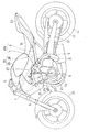
以下、本発明の好ましい実施形態について図面を参照しながら説明する。図1は、本発明の第1実施形態に係る燃料タンク装置を備えた自動二輪車を示す側面図である。この自動二輪車の車体フレームFRは、前半部を形成するメインフレーム1と、後半部を形成するリヤフレーム2とを有している。メインフレーム1は、前端に設けられたヘッドパイプ4から後方斜め下方に延びており、リヤフレーム2は、メインフレーム1の後部から後方に延びている。
Hereinafter, preferred embodiments of the present invention will be described with reference to the drawings. FIG. 1 is a side view showing a motorcycle including a fuel tank device according to a first embodiment of the present invention. A body frame FR of the motorcycle has a
ヘッドパイプ4にステアリングシャフト(図示せず)を介してフロントフォーク8が回動自在に軸支されている。フロントフォーク8の上端部に操向用のハンドル6が固定され、フロントフォーク8の下端部に前輪10が取り付けられている。
A front fork 8 is pivotally supported on the head pipe 4 via a steering shaft (not shown). A steering handle 6 is fixed to the upper end portion of the front fork 8, and a
メインフレーム1の後端部に、スイングアームブラケット9が設けられている。このスイングアームブラケット9に取り付けたピボット軸16の回りに、スイングアーム12が上下揺動自在に軸支されている。このスイングアーム12の後端部に、後輪14が回転自在に支持されている。メインフレーム1の下部でスイングアームブラケット9の前側に、エンジンEが取り付けられている。エンジンEがチェーンのような動力伝達部材11を介して後輪14を駆動する。
A
エンジンEは、クランク軸22を支持するクランクケース21と、その上部に接続されたシリンダ23と、その上方のシリンダヘッド25とを有している。シリンダ23およびシリンダヘッド25が、エンジンEの主な発熱部である。具体的には、シリンダヘッド25の後部の吸気ポート24にスロットルボディ27が接続され、スロットルボディ27に燃料噴射装置(図示せず)が内蔵されている。シリンダ23およびシリンダヘッド25の内部に、燃料と空気を導入して燃焼させる燃焼室29が形成されている。シリンダヘッド25に点火プラグ31が設けられ、その先端が燃焼室29に臨んでいる。燃料噴射装置により空気に燃料が噴射され、混合気が形成される。この混合気が燃焼室29に導入され、点火プラグ31で点火されて燃焼する。この燃焼によりコネクティングロッド(図示せず)を介してクランク軸22を回転させることによって後輪14を駆動する。したがって、シリンダ23およびシリンダヘッド25がエンジンEの主な発熱部となる。
The engine E includes a
エンジンEは、前傾姿勢で設置されており、シリンダ23およびシリンダヘッド25の軸心Xの鉛直方向からの傾斜角度θは、5〜45°程度である。エンジンEのシリンダヘッド25の上方で、メインフレーム1の上部に燃料タンク装置15が配置されている。リヤフレーム2に、ライダー用シート18および同乗者用シート20が支持されている。燃料タンク装置15は、ヘッドパイプ4とライダー用シート18との間に配置されている。
The engine E is installed in a forward tilt posture, and the tilt angle θ from the vertical direction of the axis X of the
燃料タンク装置15は、公知の方法で車体フレームFRに支持されており、燃料が貯留される燃料タンク26と、その底部に装着された燃料ポンプ28とを備えている。燃料タンク26は、上方に膨出するように湾曲し下方に開口した上板26aと、その開口を塞ぐ下板(底板)26bとが、下板26bの周縁に沿って溶接されており、下板26bが前記底部を形成している。燃料ポンプ28は、その大部分が燃料タンク26の内部に収納されており、燃料タンク26内の燃料をエンジンEへ供給する。燃料ポンプ28は、エンジンEのシリンダヘッド25の後方に位置している。
The
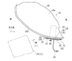
図2に示すように、燃料ポンプ28は、燃料タンク26の内部に収納されるポンプ本体30と、ポンプ本体30の下部に設けられた環状のポンプフランジ32とを有している。ポンプフランジ32は、複数のボルト挿通孔32a(図4)が形成されており、燃料タンク26の底部26bにボルト33で連結されている。本実施形態では、ボルト挿通孔32aは周方向に等間隔に5つ設けられている。燃料タンク26と燃料ポンプ28との連結構造は後述する。ポンプフランジ32およびボルト33が、燃料ポンプ28と燃料タンク26との連結部分35を構成する。
As shown in FIG. 2, the
燃料ポンプ28は、さらに、ポンプ本体30から下方に延びる燃料供給パイプ38を有している。燃料供給パイプ38に燃料チューブ(図示せず)が接続され、エンジンEに燃料が供給される。本実施形態では、ポンプフランジ32が、燃料ポンプ28における燃料タンク26からの露出部分を構成する。
The
燃料ポンプ28と燃料タンク26との連結部分35に、燃料ポンプ28をエンジンEに対して遮熱する遮熱カバー体40が取り付けられている。遮熱カバー体40は、燃料ポンプ28における燃料タンク26からの露出部分を覆っている。本実施形態では、遮熱カバー体40は、ポンプフランジ32の下面を下方から覆うとともに、ポンプフランジ32の前方を覆っている。
A heat
遮熱カバー体40は、シート状の部材を折り曲げてなり、ポンプフランジ32の下面を覆うカバー部42と、遮熱カバー体40を連結部分35に取り付ける取付部44とが形成されている。取付部44は、折り曲げ部45で後方に折り曲げられてカバー部42に連続して連なっている。つまり、遮熱カバー体40が連結部分35に取り付けられた状態で、遮熱カバー体40のカバー部42と取付部44との間の折り曲げ部45は、遮熱カバー体40の前端の前方に位置している。カバー部42と取付部44との間から燃料ポンプ28の配線46が導出されている。配線46は、燃料ポンプ28の制御線および動力線を含み、例えば、電子制御ユニット(図示せず)に接続される。
The heat
遮熱カバー体40は、断熱材からなり、折り曲げ可能な弾性部材であることが好ましい。本実施形態では、遮熱カバー体40はゴム製のシートからなる。図3は、遮熱カバー体40が取り外された状態、すなわち、遮熱カバー体40が折り曲げられる前の状態を示す平面図である。同図に示すように、遮熱カバー体40は、折り曲げ部45の前側にカバー部42が形成され、後側に取付部44が形成されている。
The heat
カバー部42は、取付部44に連なる幅広部42aと、取付部44の反対側(前側)の車幅方向D1の寸法が小さくなる幅狭部42bとを有している。同様に、取付部44は、カバー部42に連なる幅広部44aと、カバー部42の反対側(後側)の車幅方向D1の寸法が小さくなる幅狭部44bとを有している。カバー部42の幅広部42aと取付部44の幅広部44aは車幅方向D1の寸法が同じで、カバー部42の幅狭部42bと取付部44の幅狭部44bは車幅方向D1の寸法が同じである。
The
遮熱カバー体40の取付部44に、ポンプ本体30を挿通させる円形のポンプ挿通孔48が形成されている。また、取付部44におけるポンプ挿通孔48の外側に、複数の第1貫通孔50が形成されている。本実施形態では、第1貫通孔50は周方向に等間隔に5つ設けられている。つまり、第1貫通孔50は、ポンプフランジ32のボルト挿通孔32a(図4)に対応する位置に設けられている。
A circular
取付部44の幅狭部44bの端部に、車幅方向D1に並んで2組の係止溝52,52が形成されている。具体的には、各係止溝52は、車幅方向D1に延びる溝であり、長寸の第1溝54と、短寸の第2溝56とを有している。第1および第2溝54,56は、第1溝54を前方にして前後方向に並んでいる。
Two sets of locking
遮熱カバー体40のカバー部42に、燃料ポンプ28の燃料供給パイプ38を貫通させる第2貫通孔58が形成されている。また、カバー部42の幅狭部42bの端部に、各係止溝52,52に係止される係止片60,60が車幅方向D1に並んで形成されている。各係止片60は、幅狭部42bの前端から前方に延びる突片であり、前後方向に延びる帯状の係止片本体62と、係止片本体62から帯の幅方向(車幅方向D1)に突出する抜け止め部64とを有している。
A second through
係止片本体62の車幅方向D1の幅は、短寸の第2溝56の長さよりも小さい。一方、抜け止め部64の車幅方向D1の幅は、長寸の第1溝54の長さよりも若干大きく設定されている。本実施形態では、係止溝52と係止片60が2組設けられているが、1組でもよく、また、3組以上であってもよい。
The width of the locking piece
つぎに、図4および図5を用いて、燃料ポンプ28および遮熱カバー体40の燃料タンク26への取付け構造について説明する。図4に示すように、タンク本体26の底板26bに開口66が形成されている。この開口66にリング部材69が挿入され、底板26bに溶接で固着されている。詳細には、リング部材69は、内部に中空孔68が形成された円筒部70と、円筒部70の外周面から外側に延びるリングフランジ部72とを有している。円筒部70の上端部が底板26bに溶接される。
Next, a structure for attaching the
リングフランジ部72に、複数のボス部74が形成されている。ボス部74は、内部にねじ孔74aが形成された円柱形で、周方向に等間隔に5つ形成されている。このリング部材69を介して、燃料ポンプ28が燃料タンク26に取り付けられる。つまり、リング部材69と燃料ポンプ28のポンプフランジ32とにより、燃料ポンプ28と燃料タンク26との連結部分35が構成されている。
A plurality of
具体的には、リング部材69の中空孔68に、下方から燃料ポンプ28のポンプ本体30が挿入される。さらに、リング部材69の円筒部70の下端部が、遮熱カバー体40の取付部44のポンプ挿通孔48に挿通されるとともに、リングフランジ部72の各ボス部74が、遮熱カバー体40の取付部44の第1貫通孔50に挿通される。この状態で、ポンプフランジ32の各ボルト挿通孔32aに、下方からボルト33が挿通され、ボス部74のねじ孔74aに締め付けられる。これにより、遮熱カバー体40の取付部44および燃料ポンプ28が、燃料タンク26に取り付けられる。
Specifically, the
つづいて、遮熱カバー体40の折り曲げ部45でカバー部42を後方に(矢印A1の方向に)折り曲げて、図2に示すように、カバー部42によりポンプフランジ32の下面を下方から覆う。このとき、図4のカバー部42の第2貫通孔58に、燃料ポンプ28の燃料供給パイプ38を貫通させる。
Subsequently, the
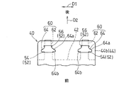
さらに、図5に示すように、カバー部42の係止片本体62を係止方向D2(前後方向)に沿って長寸の第1溝54および短寸の第2溝56の順に通過させ、抜け止め部64を長寸の第1溝54に係止する。抜け止め部64の車幅方向D1の幅寸法は、第1溝54の車幅方向D1の長さよりも若干大きいが、遮熱カバー体40はゴム製のシートからなるので、抜け止め部64を圧縮させることで、強制的に第1溝54を通過させることができる。抜け止め部64を通過させた後、圧縮状態を解除することで、抜け止め部64は第1溝54を再び通過することができなくなり、係止片60が抜け止めされる。これにより、遮熱カバー体40のカバー部42が取付部44に係止される。抜け止め部64は、第1溝54を通過させる後ろ方向に向かって徐々に幅が小さくなる傾斜部64aと、前側に形成された段差部64bとを有し、この段差部64bが第1溝54に係止されて抜け止めされる。
Further, as shown in FIG. 5, the locking piece
図6に示すように、遮熱カバー体40を装着した状態で、カバー部42の幅広部42aと取付部44の幅広部44aとが平面視で重なり、カバー部42の幅狭部42bと取付部44の幅狭部44bとが平面視で重なる。つまり、遮熱カバー体40における車幅方向D1に広い部分が前部に位置し、狭い部分が後部に位置する。発熱体であるエンジンEのシリンダヘッド25は、燃料ポンプ28の前方に位置しているので、前部を幅広とすることで、エンジンEからの熱を効果的に遮断できる。また、燃料ポンプ28の配線46は、後方の幅狭部から取り出されている。これにより、配線46の取り回しが簡単になる。
As shown in FIG. 6, the
図1に示すような自動二輪車では、一般的に、燃料タンク装置15はエンジンEの上方に配置される。燃料ポンプ28は、燃料タンク26の燃料をエンジンEに供給するので、燃料タンク26の下部に配置され、燃料タンク装置15の下方に配置されるエンジンEとの距離が近くなり易い。燃料ポンプ28をエンジンEの近くに配置すると、燃料ポンプ28とエンジンEとの間の配管を短くできるが、一方で、エンジンEにより熱せされた空気は上昇しやすいので、このような高温の空気が燃料ポンプ28に当たり易い。そのため、エンジンEの熱から燃料ポンプ28を保護する必要が生じる場合がある。
In a motorcycle as shown in FIG. 1, the
本願発明者は、鋭意研究により、エンジンEに遮熱カバー体を取り付けるよりも、図2に示すように、燃料タンク装置15側に遮熱カバー体40を取り付ける方が、エンジンからの熱が熱伝達によって直接遮熱カバーに伝わるのを防止できる分だけ、効果的に遮熱できることを見い出した。
The inventor of the present application has devised extensive research to heat the engine heat more when the heat
上記構成によれば、燃料ポンプ28と燃料タンク26との連結部分35に遮熱カバー体40が取り付けられている。これにより、覆う対象が小さくて済むので遮熱カバー体40が小形化できる。しかも、保護対象である燃料ポンプ28を確実に覆うことができるので遮熱効果も高い。したがって、燃料ポンプ28の温度が上昇するのを抑制できる。また、エンジンEには遮熱カバー体を設けないので、エンジンEの周辺に配置される部品と遮熱カバー体40との干渉を防ぐことができる。
According to the above configuration, the heat
特に、遮熱カバー体40が少なくともポンプフランジ32の下面を覆うように設けられることで、燃料タンク26からの露出部分が効果的に遮熱される。これにより、エンジンEを遮熱カバー体で覆うのに比べて、ポンプフランジ32を遮熱カバー体40で覆う面積が少なくて済むので、構造が簡単になる。
In particular, by providing the heat
また、遮熱カバー体40は、シート状の部材を折り曲げてなり、ポンプフランジ32の下面を覆うカバー部42と、カバー部42に折り曲げられて連続しポンプフランジ32に取り付けられる取付部44とを有している。このように、遮熱カバー体40の取付けに必要な取付部44と、燃料ポンプ28の遮熱を行うカバー部42とが一体に形成されているので、部品点数を低減できる。また、折り曲げ可能なシート状の部材を使用することにより、取付部44で遮熱カバー体40を取り付けた後、折り曲げ部45で折り曲げて、カバー部42によりポンプフランジ32を覆うことができる。したがって、遮熱カバー体40の取付け作業が容易である。
The heat insulating
さらに、カバー部42に形成された第2貫通孔50から燃料ポンプ28の燃料供給パイプ46が貫通しているので、カバー部42と燃料供給パイプ46との干渉が避けられるうえに、カバー部42と取付部44との隙間から燃料ポンプ28の配線46が導出されているので、配線46の設置作業が容易になる。
Further, since the
図3に示す遮熱カバー体40の取付部44に係止溝52が形成され、カバー部42に係止溝52に係止される係止片60が形成されている。これにより、係止片60を係止溝52に係止するだけでカバー部42が取付部44に支持されるから、遮熱カバー体40の取付けが容易である。また、カバー部42を支持するための部材を別途用意する必要がないから、構造が簡単である。
A locking
また、係止片60は、係止方向D2(図5)に延びる帯状の係止片本体62と、係止片本体62から帯の幅方向D1に突出する抜け止め部64とを有している。一方、係止溝52は、係止方向D2に沿って係止片本体60を通過させる短寸の第2溝56と、抜け止め部64が係止される長寸の第1溝54とを有している。これにより、図5に示すように、簡単な構造で係止片60の抜け止めが実現されるとともに、遮熱カバー体40の取付け作業の効率が向上する。
The locking
図1の燃料タンク装置15は、ヘッドパイプ4とライダー用シート18との間に配置され、図2の遮熱カバー体40の折り曲げ部45が、遮熱カバー体40の前端に位置している。これにより、閉塞された折り曲げ部45によって空気抵抗を抑制しながら、走行風AをエンジンEからの熱風と共に円滑に後方に流すことができる。その結果、燃料ポンプ28の温度が上昇するのを一層抑制することができる。
The
上記実施形態では、燃料ポンプ28と燃料タンク26との連結部分35に遮熱カバー体40が取り付けられていたが、燃料ポンプ28または燃料タンク26に遮熱カバー体40を取り付けてもよい。このような例として、例えば、椀状の遮熱カバー体を用意し、ポンプフランジ32の外周面に遮熱カバー体を嵌合してもよい。また、別の例として、ポンプフランジ32に遮熱カバー体をボルト止めしてもよい。さらに別の例として、燃料タンク26の底板26bに遮熱カバー体をボルト止めしてもよい。
In the above embodiment, the heat
これらの例によっても、エンジンEに遮熱カバー体を取り付けるのに比べて、遮熱カバー体40が小形化できるうえに、保護対象である燃料ポンプ28を確実に覆うことができるので遮熱効果も高い。したがって、燃料ポンプ28の温度が上昇するのを抑制できる。また、エンジンEに遮熱カバー体を設けないので、エンジンEの周辺に配置される部品と遮熱カバー体40との干渉を防ぐことができる。
Also in these examples, compared to the case where the heat shield cover body is attached to the engine E, the heat
本発明は、以上の実施形態に限定されるものでなく、本発明の要旨を逸脱しない範囲内で、種々の追加、変更または削除が可能である。例えば、上記実施形態では、遮熱カバー体40はポンプフランジ32の下面と前方を覆っていたが、遮熱カバー体40は少なくともポンプフランジ32の下面を覆っていればよい。本発明の燃料タンク装置は、自動二輪車以外の車両のエンジンにも適用可能で、地上に設置されるエンジンにも適用できる。したがって、そのようなものも本発明の範囲内に含まれる。
The present invention is not limited to the above-described embodiment, and various additions, modifications, or deletions can be made without departing from the gist of the present invention. For example, in the above embodiment, the heat
4 ヘッドパイプ
15 燃料タンク装置
18 ライダー用シート
26 燃料タンク
28 燃料ポンプ
30 ポンプ本体
32 ポンプフランジ
35 連結部分
38 燃料供給パイプ
40 遮熱カバー体
42 カバー部
44 取付部
45 折り曲げ部
46 配線
52 係止溝
54 第1溝
56 第2溝
58 第2貫通孔(貫通孔)
60 係止片
62 係止片本体
64 抜け止め部
E エンジン
4
60
Claims (8)
燃料タンクと、その底部に連結された燃料ポンプとを備え、
前記燃料ポンプと前記燃料タンクとの連結部分に、前記燃料ポンプにおける前記燃料タンクからの露出部分を覆って前記エンジンに対して遮熱する遮熱カバー体が取り付けられている燃料タンク装置。 A fuel tank device disposed above the engine,
A fuel tank and a fuel pump connected to the bottom of the fuel tank;
A fuel tank apparatus in which a heat shield cover body that covers the exposed portion of the fuel pump from the fuel tank and shields heat from the engine is attached to a connecting portion between the fuel pump and the fuel tank.
前記連結部分が前記ポンプフランジを含み、
前記遮熱カバー体が、少なくとも前記ポンプフランジの下面を覆っている燃料タンク装置。 2. The fuel tank device according to claim 1, wherein the fuel pump includes a pump main body, and a pump flange provided at a lower portion of the pump main body and connected to a bottom portion of the fuel tank,
The connecting portion includes the pump flange;
The fuel tank device, wherein the heat shield cover body covers at least the lower surface of the pump flange.
前記カバー部と前記取付部との間から、前記燃料ポンプの配線が導出されている燃料タンク装置。 The fuel tank device according to claim 3, wherein a through hole through which a fuel supply pipe extending from the pump main body passes is formed in the cover portion.
A fuel tank device in which wiring of the fuel pump is led out between the cover portion and the attachment portion.
前記カバー部における前記取付部と反対側の端部に、前記係止溝に係止される係止片が形成されている燃料タンク装置。 The fuel tank device according to claim 3 or 4, wherein a locking groove is formed at an end of the mounting portion opposite to the cover portion,
A fuel tank device in which a locking piece to be locked in the locking groove is formed at an end of the cover portion opposite to the mounting portion.
前記係止溝は、前記係止方向に沿って、前記係止片本体を通過させる短寸の溝と、前記抜け止め部が係止される長寸の溝とを有している燃料タンク装置。 6. The fuel tank device according to claim 5, wherein the locking piece includes a band-shaped locking piece main body extending in the locking direction and a retaining portion protruding from the locking piece main body in the width direction of the band. Have
The locking groove has a short groove that allows the locking piece main body to pass along the locking direction, and a long groove that locks the retaining portion. .
前記遮熱カバー体の前記カバー部と前記取付部との間の折り曲げ部が、前記遮熱カバー体の前端に位置している燃料タンク装置。 The fuel tank device according to any one of claims 3 to 6, wherein the fuel tank device is disposed between a head pipe of a motorcycle and a rider's seat,
The fuel tank device, wherein a bent portion between the cover portion and the attachment portion of the heat shield cover body is located at a front end of the heat shield cover body.
燃料タンクと、その底部に連結された燃料ポンプとを備え、
前記燃料ポンプまたは前記燃料タンクに、前記燃料ポンプにおける前記燃料タンクからの露出部分を覆って前記エンジンに対して遮熱する遮熱カバー体が取り付けられている燃料タンク装置。 A fuel tank device disposed above the engine,
A fuel tank and a fuel pump connected to the bottom of the fuel tank;
A fuel tank device in which a heat insulating cover body that covers an exposed portion of the fuel pump from the fuel tank and shields heat from the engine is attached to the fuel pump or the fuel tank.
Priority Applications (2)
| Application Number | Priority Date | Filing Date | Title |
|---|---|---|---|
| JP2016080166A JP6656061B2 (en) | 2016-04-13 | 2016-04-13 | Fuel tank device |
| US15/462,213 US10286777B2 (en) | 2016-04-13 | 2017-03-17 | Fuel tank apparatus |
Applications Claiming Priority (1)
| Application Number | Priority Date | Filing Date | Title |
|---|---|---|---|
| JP2016080166A JP6656061B2 (en) | 2016-04-13 | 2016-04-13 | Fuel tank device |
Publications (3)
| Publication Number | Publication Date |
|---|---|
| JP2017190036A true JP2017190036A (en) | 2017-10-19 |
| JP2017190036A5 JP2017190036A5 (en) | 2018-12-20 |
| JP6656061B2 JP6656061B2 (en) | 2020-03-04 |
Family
ID=60040018
Family Applications (1)
| Application Number | Title | Priority Date | Filing Date |
|---|---|---|---|
| JP2016080166A Active JP6656061B2 (en) | 2016-04-13 | 2016-04-13 | Fuel tank device |
Country Status (2)
| Country | Link |
|---|---|
| US (1) | US10286777B2 (en) |
| JP (1) | JP6656061B2 (en) |
Cited By (1)
| Publication number | Priority date | Publication date | Assignee | Title |
|---|---|---|---|---|
| JP2021041736A (en) * | 2019-09-06 | 2021-03-18 | 川崎重工業株式会社 | Regulator heat shielding structure of straddle-type vehicle |
Families Citing this family (1)
| Publication number | Priority date | Publication date | Assignee | Title |
|---|---|---|---|---|
| US10197023B2 (en) * | 2016-11-17 | 2019-02-05 | Ford Global Technologies, Llc | Saddle fuel tank |
Family Cites Families (5)
| Publication number | Priority date | Publication date | Assignee | Title |
|---|---|---|---|---|
| JP4116771B2 (en) | 2001-01-16 | 2008-07-09 | 本田技研工業株式会社 | Scooter type vehicle fuel system |
| JP5160247B2 (en) * | 2008-01-17 | 2013-03-13 | 本田技研工業株式会社 | Fuel tank and fuel pump mounting structure |
| JP5235089B2 (en) * | 2008-03-27 | 2013-07-10 | 本田技研工業株式会社 | Fuel pump mounting structure |
| JP5632789B2 (en) * | 2011-04-15 | 2014-11-26 | 本田技研工業株式会社 | Saddle riding |
| DE102014225309A1 (en) * | 2014-12-09 | 2016-06-09 | Robert Bosch Gmbh | Fuel pump assembly |
-
2016
- 2016-04-13 JP JP2016080166A patent/JP6656061B2/en active Active
-
2017
- 2017-03-17 US US15/462,213 patent/US10286777B2/en active Active
Cited By (2)
| Publication number | Priority date | Publication date | Assignee | Title |
|---|---|---|---|---|
| JP2021041736A (en) * | 2019-09-06 | 2021-03-18 | 川崎重工業株式会社 | Regulator heat shielding structure of straddle-type vehicle |
| JP7328837B2 (en) | 2019-09-06 | 2023-08-17 | カワサキモータース株式会社 | Straddle-type vehicle regulator heat insulation structure |
Also Published As
| Publication number | Publication date |
|---|---|
| US10286777B2 (en) | 2019-05-14 |
| JP6656061B2 (en) | 2020-03-04 |
| US20170298879A1 (en) | 2017-10-19 |
Similar Documents
| Publication | Publication Date | Title |
|---|---|---|
| US8662518B2 (en) | Vehicle with rotatable fuel tank | |
| US8448734B2 (en) | Canister mounting structure for motorcycle and motorcycle | |
| US8113312B2 (en) | Evaporative emissions canister arrangement for a motorcycle, and motorcycle incorporating same | |
| EP2664761B1 (en) | Muffler unit for saddle-ride type vehicle | |
| JP4815477B2 (en) | Mounting structure of motorcycle exhaust gas sensor | |
| JP6309379B2 (en) | Motorcycle | |
| US7793748B2 (en) | Vehicle cowl with opening for horn | |
| JP6656061B2 (en) | Fuel tank device | |
| JP2014069772A (en) | Two-wheeled vehicle | |
| CN1278036C (en) | Forced air-cooled type engine for motorcycle | |
| JP2006057565A (en) | Vehicle | |
| JP2010076751A (en) | Motorcycle | |
| EP2599991B1 (en) | Saddle riding type vehicle | |
| EP2650528B1 (en) | Motorcycle | |
| JP5118231B2 (en) | Internal combustion engine structure | |
| JP2013071492A (en) | Cooling device of internal combustion engine for saddle riding type vehicle | |
| JP2010058757A (en) | Motorcycle | |
| JP6269081B2 (en) | Injector mounting structure | |
| JP6616646B2 (en) | Heat shield structure for the intake system of motorcycle engines | |
| JP6446206B2 (en) | Vehicle cover structure | |
| JP6340809B2 (en) | Engine cooling structure | |
| JP2005225383A (en) | Lower structure of motorcycle body | |
| JP6130225B2 (en) | Heat shielding structure around the ignition switch | |
| JP2009036100A (en) | Internal combustion engine structure body and sensor attachment member | |
| JP2007076509A (en) | Motorcycle |
Legal Events
| Date | Code | Title | Description |
|---|---|---|---|
| A521 | Request for written amendment filed |
Free format text: JAPANESE INTERMEDIATE CODE: A523 Effective date: 20181108 |
|
| A621 | Written request for application examination |
Free format text: JAPANESE INTERMEDIATE CODE: A621 Effective date: 20181108 |
|
| A977 | Report on retrieval |
Free format text: JAPANESE INTERMEDIATE CODE: A971007 Effective date: 20190805 |
|
| A131 | Notification of reasons for refusal |
Free format text: JAPANESE INTERMEDIATE CODE: A131 Effective date: 20190820 |
|
| A521 | Request for written amendment filed |
Free format text: JAPANESE INTERMEDIATE CODE: A523 Effective date: 20190828 |
|
| TRDD | Decision of grant or rejection written | ||
| A01 | Written decision to grant a patent or to grant a registration (utility model) |
Free format text: JAPANESE INTERMEDIATE CODE: A01 Effective date: 20200128 |
|
| A61 | First payment of annual fees (during grant procedure) |
Free format text: JAPANESE INTERMEDIATE CODE: A61 Effective date: 20200204 |
|
| R150 | Certificate of patent or registration of utility model |
Ref document number: 6656061 Country of ref document: JP Free format text: JAPANESE INTERMEDIATE CODE: R150 |
|
| S111 | Request for change of ownership or part of ownership |
Free format text: JAPANESE INTERMEDIATE CODE: R313111 |
|
| R350 | Written notification of registration of transfer |
Free format text: JAPANESE INTERMEDIATE CODE: R350 |
|
| R250 | Receipt of annual fees |
Free format text: JAPANESE INTERMEDIATE CODE: R250 |