JP2017187902A - Business flow analysis program, business flow analysis method, and business flow analysis device - Google Patents
Business flow analysis program, business flow analysis method, and business flow analysis device Download PDFInfo
- Publication number
- JP2017187902A JP2017187902A JP2016075527A JP2016075527A JP2017187902A JP 2017187902 A JP2017187902 A JP 2017187902A JP 2016075527 A JP2016075527 A JP 2016075527A JP 2016075527 A JP2016075527 A JP 2016075527A JP 2017187902 A JP2017187902 A JP 2017187902A
- Authority
- JP
- Japan
- Prior art keywords
- work
- business
- flow
- business flow
- flow analysis
- Prior art date
- Legal status (The legal status is an assumption and is not a legal conclusion. Google has not performed a legal analysis and makes no representation as to the accuracy of the status listed.)
- Granted
Links
Images


Abstract
Description
本発明は、いわゆる業務システムのログ情報から現行業務を分析する業務フロー分析プログラム、方法および装置に関する。 The present invention relates to a business flow analysis program, method and apparatus for analyzing a current business from log information of a so-called business system.
企業の業務システムのリプレース案件において、その担当者らは、現行業務を土台にして新業務を検討するため、現行業務の実態を把握することが重要となる。しかし、現行業務の実態を把握する従来の方法として、マニュアルを参照する方法、ヒアリングする方法があるが、マニュアルは陳腐化し当てにならない、ヒアリングは特定ユーザの主観が入ってしまい客観性に欠けるなどの問題がある。 In the case of replacing a business system of a company, it is important for the persons in charge to grasp the actual situation of the current business in order to consider a new business based on the current business. However, as a conventional method of grasping the actual situation of current work, there are a method of referring to the manual and a method of hearing, but the manual is obsolete and cannot be relied on, and the hearing is not objective because the subjectivity of a specific user enters There is a problem.
これらの問題に対し、業務システム等が出力したログ情報から作業フローを生成するプロセス・マイニング技術がある。しかし、実際には膨大な数の案件の作業フローを重ね合わせたため、個々の案件がどのように流れたのかを把握するには至っていない。 For these problems, there is a process mining technology that generates a work flow from log information output by a business system or the like. However, since the work flows of a large number of cases are actually overlapped, it has not yet been possible to grasp how individual cases flowed.
これに対し、個々の案件の作業フローを、「シーケンスパタン」の出現回数が多いものを典型、そうでないものを例外に分類して表示する技術がある(特許文献1)。しかし、ログ情報から生成した、個々の案件の作業フローは、作業の実施状況を反映して様々な特性を持ち得る。前記特性とは、例えば、承認依頼時の入力間違いにより承認者に差し戻され2度承認依頼が行われる「手戻り」、業務が途中で終わっている「中断」などがあるが、それらは単に出現回数のみで仕分けられるものではない。また、特許文献1では、正常な作業フロー(のシーケンスパタン)は出現回数が最も多いという前提をおいているが、それは実用的ではなく、例えば上述した特性「中断」が最頻である場合は実際に少なくない。
本発明は、上記を鑑みて考案したものであり、企業情報システムの稼働状況を示す情報として代表的な業務アプリケーションログ情報から、業務フローを、それが持つ特性を判定して自動生成する業務フロー分析プログラム、業務フロー分析方法、業務フロー分析装置を提供する。
On the other hand, there is a technique for displaying the work flow of each case by classifying the work flow having a large number of occurrences of “sequence pattern” as a typical example and classifying the work flow as an exception (Patent Document 1). However, the work flow of each item generated from the log information can have various characteristics reflecting the work implementation status. The characteristics include, for example, “return” in which an approval request is sent back to the approver due to an input error at the time of the approval request, and “interruption” in which the work is finished halfway. They are not sorted by the number of appearances. Further, in
The present invention was devised in view of the above, and a business flow that automatically generates a business flow by determining its characteristics from typical business application log information as information indicating the operating status of a company information system An analysis program, a business flow analysis method, and a business flow analysis device are provided.
上述した課題を解決するため、本発明は、企業情報システムを利用して遂行される業務において、前記情報システムのログ情報から自動生成される業務フローを、それが持つ特性を判定してコンピュータに表示させるものである。また、本発明では、業務フロー分析において、前記ログ情報に含まれる作業を識別する作業識別子を、当該作業に付帯した前記ログ情報に含まれる案件を識別する案件識別子毎に、時系列に並べた作業列を生成するフロー抽出ステップと、前のステップで生成した作業列群から作業列が持つ特性を判定するフロー判定ステップと、前記特性が異なる作業列を区別して表示するフロー表示ステップと、を実行する。 In order to solve the above-described problems, the present invention relates to a business flow automatically generated from log information of the information system in a business performed using an enterprise information system, and determines the characteristics of the business flow and stores it in a computer. It is what is displayed. In the present invention, in the work flow analysis, work identifiers for identifying work included in the log information are arranged in time series for each case identifier for identifying a case included in the log information incidental to the work. A flow extraction step for generating a work sequence, a flow determination step for determining characteristics of the work sequence from the work sequence group generated in the previous step, and a flow display step for distinguishing and displaying the work sequences having different characteristics. Run.
また、本発明においては、業務アプリケーションログ情報から個々の案件の作業フローを抽出し、作業フローの特性を定義した「ルール」に従って、作業フローを分類し、分類した作業フローの特性を加味して、作業フローを重ね合せ、表示するものであり、作業フローには、「手戻り」や「ドロップアウト」が含まれる。 Further, in the present invention, the work flow of each item is extracted from the business application log information, the work flow is classified according to the “rule” that defines the characteristics of the work flow, and the characteristics of the classified work flow are taken into consideration. The workflows are superimposed and displayed, and the workflow includes “return” and “dropout”.
本発明により、情報システムのアプリケーションログから、業務フローを、その特性毎に区別して表現できる。このため、企業の業務システムのリプレース案件の担当者は、業務フローの頻度、パタンを、特性毎に把握することができ、現行業務の実態をより深く把握することができる。 According to the present invention, a business flow can be distinguished and expressed for each characteristic from an application log of an information system. For this reason, the person in charge of the replacement item of the business system of the company can grasp the frequency and pattern of the work flow for each characteristic, and can grasp the actual situation of the current work more deeply.
以下、本発明の実施の形態について図面を使って説明する。まず、本実施形態を概説し、その後それぞれの実施形態について説明する。 Hereinafter, embodiments of the present invention will be described with reference to the drawings. First, this embodiment will be outlined, and then each embodiment will be described.
図1は、本発明の一実施形態の概要を示す図である。コンピュータ110は、業務システムで出力されるログ情報から、業務フローを、それが持つ特性毎に区別して自動生成する。コンピュータ110は、ログ情報格納手段11、フロー抽出手段112、フロー判定手段113、フロー表示手段114を備える。
FIG. 1 is a diagram showing an outline of an embodiment of the present invention. The
業務実施情報格納手段11は、業務システム120上での業務実施情報を格納する。業務実施情報は、誰が、どのような案件の下で、どの作業を、いつ実施したのかという情報であり、少なくとも案件ID、作業ID、担当者ID、時刻を一対とするデータの集合である。業務実施情報は、例えば業務システムの運用または保守の為に常時出力しているログ情報などから抽出することができる。
The business execution
フロー抽出手段112は、業務実施情報格納手段11に格納された業務実施情報から業務フローを抽出する。具体的には、業務実施情報を(案件ID、作業ID、担当者ID、時刻)を一対とするタプルの集合とすると、同一の案件ID値を持つ作業ID値の時系列が1案件の業務フローに相当し(これをプロセス・インスタンスと呼ぶことにする)、フロー抽出手段112では、業務実施情報に含まれる全ての案件IDについてプロセス・インスタンスを生成する。
The
フロー判定手段113は、フロー抽出手段112で生成した全案件分のプロセス・インスタンスについて、プロセス・インスタンスが持つ特性を判定する。業務の実施状況は、作業の出現順序、出現回数、出現時刻間隔などに現れるため、プロセス・インスタンスを構成する作業の出現順序、出現回数、出現時刻間隔の変異を特性として判定する。
フロー表示手段114は、フロー判定手段113の結果を受け、プロセス・インスタンス群を、それが持つと判定された特性毎に区別して表示する。
The
The
次に、本発明の第1の実施形態について説明する。
図2は、本実施形態におけるシステム構成を示す図である。
業務システム210は、クライアントPC211、サーバマシン212で構成され、クライアントPC211とサーバマシン212がネットワーク213介して接続されている。業務システム210を利用する担当者は、クライアントPC211を操作して、サーバマシン212に要求を送信し、サーバマシン212上で稼働する業務アプリケーションはその要求を受信すると、プログラムに従って処理を実行する。この時、プログラム内で、前記業務実施情報を含むログ情報を出力する。
また、業務フロー分析装置220は、業務システム210とネットワーク230を介して接続され、サーバマシン212内に蓄積されているログ情報を、ネットワーク230を介して取得する。
Next, a first embodiment of the present invention will be described.
FIG. 2 is a diagram showing a system configuration in the present embodiment.
The business system 210 includes a client PC 211 and a server machine 212, and the client PC 211 and the server machine 212 are connected via a network 213. The person in charge who uses the business system 210 operates the client PC 211 to send a request to the server machine 212, and when the business application running on the server machine 212 receives the request, it executes processing according to the program. At this time, log information including the business execution information is output in the program.
Further, the business
業務フロー分析装置220およびクライアントPC211、サーバマシン212のハードウェア構成について説明する。いずれも同様のハードウェア構成によって実現できるため、業務フロー分析装置220を取り上げて説明する。
A hardware configuration of the business
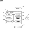
図3は、業務フロー分析装置220のハードウェア構成を示す図である。業務フロー分析装置220は、CPU(221)、主記憶装置222、外部記憶装置223で構成され、またグラフィック処理装置224を介してディスプレイ225、ネットワーク接続装置226を介してネットワーク227、入力処理装置228を介してデータ入力装置229と接続されている。外部記憶装置223には、例えば業務システム210のサーバマシンに蓄積されたログ情報をファイルとして格納することも可能である。また、主記憶装置222には、CPU(221)が実行可能な形式でプログラムが展開され、データ入力装置229から受け取ったデータをプログラムの実行時の入力情報とし、またプログラムの出力結果をディスプレイ225に表示することも可能である。
FIG. 3 is a diagram illustrating a hardware configuration of the business
次に、業務フロー分析装置220の機能構成について説明する。
図4は、業務フロー分析装置220の機能構成を示すブロック図である。業務フロー分析装置220は、業務実施情報格納部411、フロー抽出部412、フロー判定部413、フロー表示部414、終端作業格納部415で構成される。
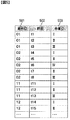
業務実施情報格納部411は、業務システム210上における業務の実施情報を格納する。業務の実施情報とは、誰が、どのような案件の下で、どの作業を、いつ実施したのかという情報であり、本実施例では案件ID、作業ID、時刻を一対とするデータの集合である。図5は本実施例で用いる業務実施情報のデータ構造を示したテーブルである。なお、案件ID(501)について予めソートしてあり、案件ID=01、02、11、12に関するレコードは図5に現れている以外はないものとする。また、時刻(502)は整数i、jに対し、i<jであれば時刻ti<tjである。本実施例では、業務システム210の運用または保守の為に常時出力・蓄積しているログ情報を、ネットワーク227を介して取得し、業務の実施情報を抽出することができるものとする。
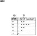
フロー抽出部412は、業務実施情報格納部411に格納された業務実施情報から、前記プロセス・インスタンスを抽出する。図6は、フロー抽出部412によって抽出されたプロセス・インスタンスの例である。案件ID(601)=”01”である案件について、作業がI、II、IIIの順番に実施されたことを表している。
Next, the functional configuration of the business
FIG. 4 is a block diagram showing a functional configuration of the business
The business execution
The flow extraction unit 412 extracts the process instance from the business execution information stored in the business execution
フロー判定部413は、フロー抽出部412で抽出された全案件のプロセス・インスタンスを、業務フロー分析装置220を利用するユーザが選択した業務フローの判定方法に従って判定する。本実施例では、フロー判定部413は、2つの業務フロー判定方法を持つものとする。第1の業務フロー判定方法は、手戻りが発生した業務フローを判定する方法で、ある案件のプロセス・インスタンスにおいて、2回出現した作業が存在する時、1回目出現以降の作業から2回目までの部分作業列を“手戻り”と判定する。次に、第2の業務フロー判定方法は、業務が中断している業務フローを判定する方法で、ある案件のプロセス・インスタンスにおいて予め与えられた「終端作業」を含まないものを“業務中断”と判定する。図7は、フロー判定部413の出力結果を示すテーブル700である。テーブル700は、図5で示した業務実施情報のテーブルが持つ案件IDカラム、時刻カラム、作業IDカラムに、判定区分カラムを加えたものである。第1の業務フロー判定方法に関して、案件ID=”02”であるプロセス・インスタンスにおいてはレコード701、702が指す部分作業列が”手戻り”と判定され、その判定区分カラムの値は“手戻り”となっている。また、第2の業務フロー判定方法に関して、案件ID=”12”であるプロセス・インスタンスにおいては、後述する終端作業格納部415に格納されている終端作業“III”を含まないため“業務中断”と判定され、そのプロセス・インスタンスの末尾に業務中断を示すレコード703を追加している。
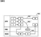
フロー表示部414は、フロー判定部413で判定されたプロセス・インスタンスを、業務フロー分析装置220が持つディスプレイ225などに表示する。図8は、フロー判定部413の出力結果700を表示した表示例800であるが、説明の都合上業務フロー800を描画する途中段階の業務フロー900を用いて説明する。業務フロー902は業務が最後まで到達しておらず「中断」の特性を持つと判定されたものであり、業務フロー903は同一作業が2回出現し「手戻り」の特性を持つと判定されたものであり、業務フロー901は特に特性を持たないため「正常」と判定されたものである。それぞれの業務フローは、「中断」スイムレーン、「手戻り」スイムレーン、「正常」スイムレーン上に配置される。例えば、案件ID=“01”のプロセス・インスタンス(901)の各作業は、その判定区分はいずれも“正常”であるため正常スイムレーンに配置されているが、案件ID=“02”のプロセス・インスタンス(903)では、時刻t6、t7である作業の判定区分は手戻りであるため手戻りスイムレーンに配置されているが、それ以外(=時刻t4、t5、t8の作業)は正常スイムレーンに配置される。業務フロー900において、同一スイムレーン上にある同一作業を重ね合わせて業務フロー800を得る。
The
The
終端作業格納部415は、業務の完了を意味する作業の作業識別子の値を格納する。図10は、終端作業格納部415に格納された終端作業リストを示すテーブルである。本実施形態では、作業ID=“III”が終端作業であるとする。
The terminal
以下では、上述した機能構成における各部の動作を説明する。
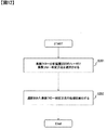
図11は、フロー抽出部412の処理手順を示すフローチャートである。フロー抽出部412は、業務フロー分析装置220の処理開始を受けて開始する。フロー抽出部412は、まず業務実施情報格納部411に格納された業務実施情報から全ての案件IDを取得する(ステップS101)。ステップS101で取得した案件ID毎に、これから述べるステップS102とS103を、この順に繰り返す。ステップS102では選択された1つの案件IDに関連する業務実施情報を抽出する。図5で示した業務実施情報を例にとると、選択された案件IDが“01”の場合、時刻t1、t2、t3であるレコードを抽出する。次にステップS103では、ステップS102で抽出したレコードを時系列に並び替える。このようにして、業務実施情報格納部411に格納された業務実施情報から、各案件IDに関するプロセス・インスタンスを抽出する。
Below, operation | movement of each part in the function structure mentioned above is demonstrated.
FIG. 11 is a flowchart illustrating a processing procedure of the flow extraction unit 412. The flow extraction unit 412 starts upon receiving the processing start of the business
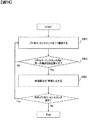
図12は、フロー判定部413の処理手順を示すフローチャートである。フロー判定部413は、フロー抽出部412の終了を受けて開始する。フロー判定部413は、まず業務フロー分析装置220のユーザに対して、フロー判定部413が有する業務フロー判定方法から選択させるよう促す(ステップS201)。図13は、フロー判定部413が、前記ユーザに対して、業務フロー判定方法の選択を促す画面例1300である。前記業務フロー判定方法について、チェックボックスなどの画面要素1301を利用することで、前記業務フロー判定方法の少なくとも1つを選択させることができる。なお、業務フロー判定方法選択画面例1300では、前記業務フロー判定方法の両方を選択している。その上で、ボタンなどの画面要素1302を押下することで、前記ユーザはフロー判定部413に対して選択した判定方法を送信する。次に、フロー判定部413は、ステップ201で選択された業務フロー判定方法の処理を実行する(ステップS202)。
FIG. 12 is a flowchart illustrating a processing procedure of the
ここで、ステップS202では、第1および第2の業務フロー判定方法に対し、少なくとも一方の処理が実行される。図14、15は、第1、第2の業務フロー判定方法の処理手順を示したフローチャートである。
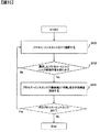
第1の業務フロー判定方法の処理手順について説明する。本処理は、フロー判定部413のステップS202からの処理開始を受けて、開始する。まず、フロー判定部413は、フロー抽出部412で抽出した全案件のプロセス・インスタンスから1つ選択する(S301)。次に、選択したプロセス・インスタンス内に同一作業が2回出現しているかを調べ、あれば次のステップ303に進み、なければステップ301に戻る(S302)。ステップ303では、2回出現した作業(Rとする)のうち、1回目の作業Rの次の作業から、最後に出現した作業Rまでの各作業の判定区分を「手戻り」とする。次のプロセス・インスタンスがあればステップS301に戻り、なければ第1の業務フロー判定方法の処理を終了する。
Here, in step S202, at least one of the processes is executed for the first and second business flow determination methods. 14 and 15 are flowcharts showing the processing procedure of the first and second business flow determination methods.
A processing procedure of the first business flow determination method will be described. This process starts upon receiving the process start from step S202 of the
第2の業務フロー判定方法の処理手順について説明する。本処理は、フロー判定部413のステップS202からの処理開始を受けて、開始する。まず、フロー判定部413は、フロー抽出部412で抽出した全案件のプロセス・インスタンスから1つ選択する(S401)。次に、選択したプロセス・インスタンスが終端作業格納部415に格納された終端作業を含むかを調べ、含むなら次のステップ403に進み、含まなければステップS401に戻る(S402)。ステップ403では、プロセス・インスタンスの最後尾に、例えば「ドロップアウト」という作業名で、判定区分を「中断」とした作業を追加する。次のプロセス・インスタンスがあればステップS401に戻り、なければ第2の業務フロー判定方法の処理を終了する。
A processing procedure of the second business flow determination method will be described. This process starts upon receiving the process start from step S202 of the
図16は、フロー表示部414の処理手順を示すフローチャートである。本処理は、フロー判定部413の処理終了を受けて、開始する。ここでは、フロー判定部413の出力結果700を例に説明する。まず、フロー表示部414は、前記出力結果700を参照し、判定区分値の種類数だけスイムレーンを用意する(S501)。本実施例では、スイムレーン名は判定区分値とした。次に、前記出力結果700を参照し、プロセス・インスタンスを1つ選択する(S502)。次に、そのプロセス・インスタンスの各作業を、その判定区分に対応するスイムレーンに配置する(S503)。なお、例では、作業は角丸四角で表現し、作業と次の作業を矢印で結ぶものとした。次に同一スイムレーンに同一作業がある場合はそれらを重ね合わせる(S504)。次のプロセス・インスタンスがあればステップS502に戻り、なければ本処理を終了する。
FIG. 16 is a flowchart showing the processing procedure of the
120…業務システム、110…コンピュータ
120 ... business system, 110 ... computer
Claims (6)
前記ログ情報に含まれる作業を識別する作業識別子を、当該作業に付帯した前記ログ情報に含まれる案件を識別する案件識別子毎に、時系列に並べた作業列を生成するフロー抽出ステップと、
直前のステップで生成した作業列群から作業列が持つ特性を判定するフロー判定ステップと、
前記特性が異なる作業列を区別して表示するフロー表示ステップと、をコンピュータに実行させる業務フロー分析プログラム。 A business flow analysis program for determining a characteristic of a business flow automatically generated from log information of the information system and displaying it on a computer for a business performed using a business system,
A flow extraction step for generating a work sequence arranged in chronological order for each work identifier for identifying a work identifier for identifying a work included in the log information, a work identifier for identifying a work included in the log information;
A flow determination step for determining characteristics of the work sequence from the work sequence group generated in the immediately preceding step;
A business flow analysis program for causing a computer to execute a flow display step of distinguishing and displaying work rows having different characteristics.
前記特性には、前記作業の手戻りおよびドロップアウトが含まれることを特徴とする業務フロー分析プログラム。 In the business flow analysis program according to claim 1,
The business flow analysis program characterized in that the characteristics include rework and dropout of the work.
前記ログ情報に含まれる作業を識別する作業識別子を、当該作業に付帯した前記ログ情報に含まれる案件を識別する案件識別子毎に、時系列に並べた作業列を生成するフロー抽出手段と、
直前のステップで生成した作業列群から作業列が持つ特性を判定するフロー判定手段と、
前記特性が異なる作業列を区別して表示するフロー表示手段とを有することを特徴とする業務フロー分析システム。 A business flow analysis system for determining a characteristic of a business flow automatically generated from log information of the information system for a business performed using the business system,
A flow extraction unit for generating a work sequence arranged in time series for each case identifier for identifying a case included in the log information attached to the work, a work identifier for identifying the work included in the log information;
A flow determination means for determining characteristics of the work sequence from the work sequence group generated in the immediately preceding step;
A business flow analysis system comprising: flow display means for distinguishing and displaying work rows having different characteristics.
前記特性には、前記作業の手戻りおよびドロップアウトが含まれることを特徴とする業務フロー分析システム。 In the business flow analysis system according to claim 3,
The business flow analysis system characterized in that the characteristics include rework and dropout of the work.
前記コンピュータは、
前記ログ情報に含まれる作業を識別する作業識別子を、当該作業に付帯した前記ログ情報に含まれる案件を識別する案件識別子毎に、時系列に並べた作業列を生成するフロー抽出し、
直前のステップで生成した作業列群から作業列が持つ特性を判定し、
前記特性が異なる作業列を区別して表示することを特徴とする業務フロー分析方法。 A business flow analysis method for determining a characteristic of a business flow automatically generated from log information of the information system and displaying it on a computer for a business performed using a business system,
The computer
A work identifier for identifying a work included in the log information is extracted for each case identifier for identifying a case included in the log information attached to the work, and a flow is generated to generate a work sequence arranged in time series,
Determine the characteristics of the work sequence from the work sequence group generated in the previous step,
A work flow analysis method characterized by distinguishing and displaying work rows having different characteristics.
前記特性には、前記作業の手戻りおよびドロップアウトが含まれることを特徴とする業務フロー分析方法。 The business flow analysis method according to claim 5,
The business flow analysis method according to claim 1, wherein the characteristics include rework and dropout of the work.
Priority Applications (1)
| Application Number | Priority Date | Filing Date | Title |
|---|---|---|---|
| JP2016075527A JP6738637B2 (en) | 2016-04-05 | 2016-04-05 | Business flow analysis program, business flow analysis method, and business flow analysis device |
Applications Claiming Priority (1)
| Application Number | Priority Date | Filing Date | Title |
|---|---|---|---|
| JP2016075527A JP6738637B2 (en) | 2016-04-05 | 2016-04-05 | Business flow analysis program, business flow analysis method, and business flow analysis device |
Publications (2)
| Publication Number | Publication Date |
|---|---|
| JP2017187902A true JP2017187902A (en) | 2017-10-12 |
| JP6738637B2 JP6738637B2 (en) | 2020-08-12 |
Family
ID=60046431
Family Applications (1)
| Application Number | Title | Priority Date | Filing Date |
|---|---|---|---|
| JP2016075527A Active JP6738637B2 (en) | 2016-04-05 | 2016-04-05 | Business flow analysis program, business flow analysis method, and business flow analysis device |
Country Status (1)
| Country | Link |
|---|---|
| JP (1) | JP6738637B2 (en) |
Cited By (2)
| Publication number | Priority date | Publication date | Assignee | Title |
|---|---|---|---|---|
| JP2020052451A (en) * | 2018-09-21 | 2020-04-02 | 株式会社日立製作所 | Computer system and pattern generation method of business flow |
| JPWO2021084664A1 (en) * | 2019-10-30 | 2021-05-06 |
Citations (4)
| Publication number | Priority date | Publication date | Assignee | Title |
|---|---|---|---|---|
| JP2006236125A (en) * | 2005-02-25 | 2006-09-07 | Fujitsu Ltd | Business information management program |
| JP2010020634A (en) * | 2008-07-11 | 2010-01-28 | Fujitsu Ltd | Workflow processing program, method, and device |
| JP2012022602A (en) * | 2010-07-16 | 2012-02-02 | Mitsubishi Electric Corp | Operation improvement analysis system |
| JP2014048673A (en) * | 2012-08-29 | 2014-03-17 | Hitachi Ltd | Workflow generation server and method |
-
2016
- 2016-04-05 JP JP2016075527A patent/JP6738637B2/en active Active
Patent Citations (4)
| Publication number | Priority date | Publication date | Assignee | Title |
|---|---|---|---|---|
| JP2006236125A (en) * | 2005-02-25 | 2006-09-07 | Fujitsu Ltd | Business information management program |
| JP2010020634A (en) * | 2008-07-11 | 2010-01-28 | Fujitsu Ltd | Workflow processing program, method, and device |
| JP2012022602A (en) * | 2010-07-16 | 2012-02-02 | Mitsubishi Electric Corp | Operation improvement analysis system |
| JP2014048673A (en) * | 2012-08-29 | 2014-03-17 | Hitachi Ltd | Workflow generation server and method |
Cited By (5)
| Publication number | Priority date | Publication date | Assignee | Title |
|---|---|---|---|---|
| JP2020052451A (en) * | 2018-09-21 | 2020-04-02 | 株式会社日立製作所 | Computer system and pattern generation method of business flow |
| JP7041603B2 (en) | 2018-09-21 | 2022-03-24 | 株式会社日立製作所 | How to generate patterns for computer systems and business flows |
| JPWO2021084664A1 (en) * | 2019-10-30 | 2021-05-06 | ||
| WO2021084664A1 (en) * | 2019-10-30 | 2021-05-06 | 日本電信電話株式会社 | Extraction device, extraction method, and extraction program |
| JP7226582B2 (en) | 2019-10-30 | 2023-02-21 | 日本電信電話株式会社 | Extraction device, extraction method and extraction program |
Also Published As
| Publication number | Publication date |
|---|---|
| JP6738637B2 (en) | 2020-08-12 |
Similar Documents
| Publication | Publication Date | Title |
|---|---|---|
| JP5475203B1 (en) | Workflow management apparatus and workflow management method | |
| CN108629558B (en) | Software development management system | |
| EP1564671A1 (en) | Process editing apparatus and method and process management apparatus and method | |
| CA2663216A1 (en) | Workflow definition and management system | |
| US20150302328A1 (en) | Work Environment Recommendation Based on Worker Interaction Graph | |
| JP2010157183A (en) | Apparatus and program for processing information | |
| JP2019168844A (en) | Task management system, server device, its control method, and program | |
| JP5856906B2 (en) | Business problem analysis support system | |
| JP5651792B2 (en) | Workflow management apparatus and workflow management method | |
| JP2017187902A (en) | Business flow analysis program, business flow analysis method, and business flow analysis device | |
| JP6840021B2 (en) | Business process analyzer, business process analysis method, and business process analysis program | |
| WO2016121633A1 (en) | Operation specification reproduction system and operation specification reproduction method | |
| JP6639334B2 (en) | Business process flow generation system, generation method and apparatus | |
| JP2017016507A (en) | Test management system and program | |
| US20130290065A1 (en) | Method and System to Analyze Processes | |
| JP2008065711A (en) | Evaluation method of business efficiency improvement and evaluation program of business efficiency improvement | |
| JPWO2014057559A1 (en) | Work slip recording support system and program | |
| WO2017002249A1 (en) | Workflow management program, workflow management method, and workflow management device | |
| JP2018032257A (en) | Information processing device, information processing system, information processing program, and information processing method | |
| Van der Aalst | Discovering coordination patterns using process mining | |
| CN111401831A (en) | Task progress display method, device and equipment and readable storage medium | |
| JP2005190212A (en) | Database system, data processing method and program | |
| JP2003256606A (en) | Service quality evaluation index select device, method, program and program recording medium | |
| JP2005215857A (en) | Resource assignment system for solution business | |
| JP6705135B2 (en) | Data input system, data input method, and program |
Legal Events
| Date | Code | Title | Description |
|---|---|---|---|
| RD04 | Notification of resignation of power of attorney |
Free format text: JAPANESE INTERMEDIATE CODE: A7424 Effective date: 20170111 |
|
| RD04 | Notification of resignation of power of attorney |
Free format text: JAPANESE INTERMEDIATE CODE: A7424 Effective date: 20170113 |
|
| A621 | Written request for application examination |
Free format text: JAPANESE INTERMEDIATE CODE: A621 Effective date: 20180906 |
|
| RD02 | Notification of acceptance of power of attorney |
Free format text: JAPANESE INTERMEDIATE CODE: A7422 Effective date: 20190226 |
|
| RD04 | Notification of resignation of power of attorney |
Free format text: JAPANESE INTERMEDIATE CODE: A7424 Effective date: 20190326 |
|
| A977 | Report on retrieval |
Free format text: JAPANESE INTERMEDIATE CODE: A971007 Effective date: 20190709 |
|
| A131 | Notification of reasons for refusal |
Free format text: JAPANESE INTERMEDIATE CODE: A131 Effective date: 20190827 |
|
| A521 | Request for written amendment filed |
Free format text: JAPANESE INTERMEDIATE CODE: A523 Effective date: 20190912 |
|
| A02 | Decision of refusal |
Free format text: JAPANESE INTERMEDIATE CODE: A02 Effective date: 20200303 |
|
| A521 | Request for written amendment filed |
Free format text: JAPANESE INTERMEDIATE CODE: A523 Effective date: 20200421 |
|
| A911 | Transfer to examiner for re-examination before appeal (zenchi) |
Free format text: JAPANESE INTERMEDIATE CODE: A911 Effective date: 20200430 |
|
| TRDD | Decision of grant or rejection written | ||
| A01 | Written decision to grant a patent or to grant a registration (utility model) |
Free format text: JAPANESE INTERMEDIATE CODE: A01 Effective date: 20200623 |
|
| A61 | First payment of annual fees (during grant procedure) |
Free format text: JAPANESE INTERMEDIATE CODE: A61 Effective date: 20200720 |
|
| R150 | Certificate of patent or registration of utility model |
Ref document number: 6738637 Country of ref document: JP Free format text: JAPANESE INTERMEDIATE CODE: R150 |