JP2017187130A - Power transmission device and drive unit - Google Patents
Power transmission device and drive unit Download PDFInfo
- Publication number
- JP2017187130A JP2017187130A JP2016077087A JP2016077087A JP2017187130A JP 2017187130 A JP2017187130 A JP 2017187130A JP 2016077087 A JP2016077087 A JP 2016077087A JP 2016077087 A JP2016077087 A JP 2016077087A JP 2017187130 A JP2017187130 A JP 2017187130A
- Authority
- JP
- Japan
- Prior art keywords
- magnets
- rotor
- rotor disk
- rotating shaft
- power transmission
- Prior art date
- Legal status (The legal status is an assumption and is not a legal conclusion. Google has not performed a legal analysis and makes no representation as to the accuracy of the status listed.)
- Granted
Links
Images


Abstract
Description
本発明は、磁気歯車を用いた動力伝達装置および駆動装置に関するものである。 The present invention relates to a power transmission device and a drive device using a magnetic gear.
従来から、磁気歯車を用いた動力伝達装置が研究・開発されている。例えば、特許文献1には、動力伝達装置の一例である磁気歯車減速機の構造が開示されている。 Conventionally, a power transmission device using a magnetic gear has been researched and developed. For example, Patent Document 1 discloses a structure of a magnetic gear reducer that is an example of a power transmission device.
特許文献1に開示の技術では、電動モータの出力軸と、ウォームギア機構部のウォーム軸との間の動力伝達に、非接触型の動力伝達装置が採用されている。具体的には、電動モータの出力軸とウォームギア機構部のウォーム軸とは、平行かつ偏心して配置されている。出力軸の端部、およびウォーム軸の端部には、それぞれ円盤形状のディスクが固着されている。ウォーム軸の側のディスクは、出力軸の側のディスクよりも大径となっている。そして、各ディスクにおける互いの対向面には、それぞれの外縁部に複数の磁石が平面視円環状に設けられている。ウォーム軸の側のディスクに設けられた磁石と、出力軸の側のディスクに設けられた磁石とは、一部同士が対向するようになっている。 In the technique disclosed in Patent Document 1, a non-contact power transmission device is employed for power transmission between the output shaft of the electric motor and the worm shaft of the worm gear mechanism. Specifically, the output shaft of the electric motor and the worm shaft of the worm gear mechanism are arranged in parallel and eccentric. Disc-shaped discs are fixed to the end of the output shaft and the end of the worm shaft, respectively. The disk on the worm shaft side has a larger diameter than the disk on the output shaft side. A plurality of magnets are provided on the outer edges of the respective disks in an annular shape in plan view on the respective outer edges. The magnet provided on the disk on the worm shaft side and the magnet provided on the disk on the output shaft side are partially opposed to each other.
このような磁気歯車を用いた非接触型の動力伝達装置では、直接的・物理的に接触する歯車を用いた動力伝達装置よりも、伝達ロスを低減することができる。 In a non-contact power transmission device using such a magnetic gear, transmission loss can be reduced as compared with a power transmission device using a gear that is in direct and physical contact.
しかしながら、特許文献1に開示された動力伝達装置では、信頼性の観点での問題が生じる。即ち、特許文献1に開示の動力伝達装置では、ウォーム軸の側のディスクに設けられた磁石と、出力軸の側のディスクに設けられた磁石とが、互いに出力軸およびウォーム軸の軸方向に対向している。このため、特許文献1に開示の動力伝達装置では、磁石同士の引き合う力が作用し、この力により、出力軸およびウォーム軸に対して、それらの軸方向に力が連続的に作用することになる。よって、特許文献1に開示の動力伝達装置では、出力軸およびウォーム軸、さらにはこれらの軸受に対して、対向する磁石同士の引き合う力に起因する負荷が常に作用することになり、信頼性の観点で問題を生じる。 However, the power transmission device disclosed in Patent Document 1 has a problem in terms of reliability. That is, in the power transmission device disclosed in Patent Document 1, the magnet provided on the disk on the worm shaft side and the magnet provided on the disk on the output shaft side are in the axial direction of the output shaft and the worm shaft. Opposite. For this reason, in the power transmission device disclosed in Patent Document 1, a force that attracts magnets acts, and this force causes the force to continuously act in the axial direction on the output shaft and the worm shaft. Become. Therefore, in the power transmission device disclosed in Patent Document 1, a load caused by the attractive force between the opposing magnets always acts on the output shaft and the worm shaft, and further on these bearings, and the reliability is high. Problems arise from a viewpoint.
本発明は、伝達ロスの低減を図ることができるとともに、高い信頼性を実現することができる動力伝達装置および駆動装置を提供することを目的とする。 It is an object of the present invention to provide a power transmission device and a driving device that can reduce transmission loss and can achieve high reliability.
本発明の一態様に係る動力伝達装置は、第1ロータおよび第2ロータを備える。第1ロータは、第1方向に延びる第1回転軸と、第1回転軸に固定され、第1方向に直交する第2方向を径方向とする第1ロータディスクと、第1ロータディスクの一方の主面の外縁部、および第1ロータディスクの他方の主面の外縁部に平面視円環状に配置されてなる複数の第1磁石と、を有する。 A power transmission device according to an aspect of the present invention includes a first rotor and a second rotor. The first rotor includes a first rotating shaft extending in a first direction, a first rotor disk fixed to the first rotating shaft and having a second direction perpendicular to the first direction as a radial direction, and one of the first rotor disks And a plurality of first magnets arranged in an annular shape in plan view at the outer edge of the other main surface of the first rotor disk.
第2ロータは、第1方向に延び、かつ、第1回転軸に対して第2方向に間隔をあけて配置されてなる第2回転軸と、第2回転軸に固定され、第2方向を径方向とし、かつ、第1ロータディスクと第1方向に間隔をあけて配置されてなる第2ロータディスクと、第2回転軸に固定され、第2方向を径方向とし、かつ、第1方向において第1ロータディスクを挟んで第2ロータディスクとは反対側に、第1ロータディスクと第1方向に間隔をあけて配置されてなる第3ロータディスクと、第2ロータディスクにおける第1方向の第1ロータディスクの側の主面の外縁部に、平面視円環状に配置されてなる複数の第2磁石と、第3ロータディスクにおける第1方向の第1ロータディスクの側の主面の外縁部に、平面視円環状に配置されてなる複数の第3磁石と、を有する。 The second rotor extends in the first direction and is disposed at an interval in the second direction with respect to the first rotation shaft, and is fixed to the second rotation shaft, and has a second direction. A second rotor disk having a radial direction and being spaced apart from the first rotor disk in the first direction; and being fixed to the second rotating shaft, the second direction being a radial direction, and the first direction In FIG. 3, a third rotor disk is disposed on the opposite side of the first rotor disk from the second rotor disk, and is spaced from the first rotor disk in the first direction, and the second rotor disk in the first direction. A plurality of second magnets arranged in an annular shape in plan view on the outer edge portion of the main surface on the first rotor disk side, and the outer edge of the main surface on the first rotor disk side in the first direction in the third rotor disk A plurality of parts arranged in an annular shape in plan view 3 has a magnet, a.
複数の第1磁石の一部と、複数の第2磁石の一部および複数の第3磁石の一部とは、互いに間隔をあけた状態で対向し、第1ロータと第2ロータとは、複数の第1磁石と、複数の第2磁石および複数の第3磁石との磁力をもって同期した状態で連動することを特徴とする。 A portion of the plurality of first magnets, a portion of the plurality of second magnets, and a portion of the plurality of third magnets face each other with a space therebetween, and the first rotor and the second rotor are The plurality of first magnets, the plurality of second magnets, and the plurality of third magnets are interlocked in a synchronized state with magnetic force.
この態様に係る動力伝達装置では、第1方向において、第1ロータの第1ロータディスクが、第2ロータの第2ロータディスクと第3ロータディスクとの間に配置されている。そして、第1ロータディスクの一方の主面に配置された複数の第1磁石の一部と、第2ロータディスクの対向主面に配置された複数の第2磁石の一部とが間隔をあけて対向し、当該対向部分で磁力が作用する。同様に、第1ロータディスクの他方の主面に配置された複数の第1磁石の一部と、第3ロータディスクの対向主面に配置された複数の第3磁石の一部とが間隔をあけて対向し、当該対向部分でも磁力が作用する。このような構成を採用する本態様に係る動力伝達装置では、第1ロータおよび第2ロータの回転時において、対向領域において互いに対向する第1磁石と第2磁石とが引き合う力と、同じく対向領域において互いに対向する第1磁石と第3磁石とが引き合う力とが、互いに相殺する関係の向きに作用する。よって、本態様に係る動力伝達装置では、第1回転軸および第2回転軸にかかる第1方向での力の相殺を図ることができ、第1方向の一方にだけ連続的に力が発生することがない。 In the power transmission device according to this aspect, in the first direction, the first rotor disk of the first rotor is disposed between the second rotor disk and the third rotor disk of the second rotor. A part of the plurality of first magnets arranged on one main surface of the first rotor disk and a part of the plurality of second magnets arranged on the opposing main surface of the second rotor disk are spaced from each other. The magnetic force acts on the facing portion. Similarly, a part of the plurality of first magnets arranged on the other main surface of the first rotor disk and a part of the plurality of third magnets arranged on the opposing main surface of the third rotor disk are spaced from each other. It opens and opposes, and a magnetic force acts also in the said opposing part. In the power transmission device according to this aspect that employs such a configuration, when the first rotor and the second rotor are rotated, the force that the first magnet and the second magnet that face each other in the opposing region attract each other, and the same opposing region. The force attracted by the first magnet and the third magnet facing each other in FIG. Therefore, in the power transmission device according to this aspect, it is possible to cancel the force in the first direction applied to the first rotating shaft and the second rotating shaft, and the force is continuously generated only in one of the first directions. There is nothing.
また、本態様に係る動力伝達装置は、磁気歯車を用いた非接触型の動力伝達装置であるので、直接的・物理的に接触する歯車を用いた動力伝達装置よりも、伝達ロスの低減を図ることができる。特に、入力回転数が超高回転(例えば、100000rpm以上)の場合などには、高い伝達効率の実現という観点から好適である。 In addition, since the power transmission device according to this aspect is a non-contact type power transmission device using magnetic gears, the transmission loss is reduced more than the power transmission device using gears that are in direct and physical contact. Can be planned. In particular, when the input rotational speed is an extremely high rotation (for example, 100000 rpm or more), it is preferable from the viewpoint of realizing high transmission efficiency.
以上のように、本態様に係る動力伝達装置は、伝達ロスの低減を図ることができるとともに、高い信頼性を実現することができる。 As described above, the power transmission device according to this aspect can reduce transmission loss and achieve high reliability.
また、本発明の別態様に係る動力伝達装置では、上記態様の構成において、複数の第1磁石の一部と、複数の第2磁石の一部および複数の第3磁石の一部とが互いに間隔をあけた状態で対向する領域(「対向領域」ということがある)において、対向する第1磁石と第2磁石は、一方がS極であって、他方がN極であり、対向する第1磁石と前記第3磁石は、一方がS極であって、他方がN極であり、かつ、第1ロータディスクをその厚み方向に挟んで第1方向に背中合わせに配置された2つの第1磁石は、一方がS極であって、他方がN極である、とすることもできる。 In the power transmission device according to another aspect of the present invention, in the configuration of the above aspect, a part of the plurality of first magnets, a part of the plurality of second magnets, and a part of the plurality of third magnets are mutually connected. In a region opposite to each other with a gap (sometimes referred to as “opposing region”), one of the first and second magnets facing each other is an S pole and the other is an N pole, One of the first magnet and the third magnet is an S pole and the other is an N pole, and the two first magnets are arranged back to back in the first direction with the first rotor disk sandwiched in the thickness direction. One of the magnets can be an S pole and the other an N pole.
この態様に係る動力伝達装置では、対向する第1磁石と第2磁石を互いに異なる極とし、かつ、対向する第1磁石と第3磁石を互いに異なる極とし、かつ、第1ロータディスクをその厚み方向に挟んで背中合わせに配置される2つの第1磁石を互いに異なる極としている。これにより、対向する磁石同士には、引き合う力が発生し、反発しあう力は発生しない。また、第1ロータディスクの厚み方向での磁極の関係も同様となる。このため、滑らかな磁束の流れを形成しやすくなり、伝達効率の向上を図ることができる。 In the power transmission device according to this aspect, the first and second magnets facing each other have different poles, the first and third magnets facing each other have different poles, and the first rotor disk has a thickness thereof. Two first magnets arranged back to back across the direction are different from each other. Thereby, the attracting force is generated between the opposing magnets, and no repulsive force is generated. The relationship between the magnetic poles in the thickness direction of the first rotor disk is the same. For this reason, it becomes easy to form a smooth magnetic flux flow, and the transmission efficiency can be improved.
また、本発明の別態様に係る動力伝達装置では、上記態様の構成において、第2ロータディスクおよび第3ロータディスクおよび第2回転軸が磁性材料からなる、とすることもできる。 In the power transmission device according to another aspect of the present invention, in the configuration of the above aspect, the second rotor disk, the third rotor disk, and the second rotation shaft may be made of a magnetic material.
この態様に係る動力伝達装置では、上記優位性に加え、第1ロータディスクと第2ロータディスクと第2回転軸と第3ロータディスクとの各一部でのループで、磁束の流れを形成することができる。これにより伝達効率のさらなる向上を図ることができるという優位性も得ることができる。 In the power transmission device according to this aspect, in addition to the above advantages, a flow of magnetic flux is formed by a loop in each part of the first rotor disk, the second rotor disk, the second rotating shaft, and the third rotor disk. be able to. Thereby, the advantage that the transmission efficiency can be further improved can be obtained.
また、本発明の別態様に係る動力伝達装置では、上記態様の構成において、複数の第1磁石の一部と、複数の第2磁石の一部および複数の第3磁石の一部とが対向する領域における、磁石対向面積をS1、S2とし、第2ロータディスク、および第3ロータディスクにおける、内部磁路面積をS3、S4とし、第2回転軸の第2方向での断面積をS5とするとき、S1およびS2に対して、S3およびS4およびS5が同等以上である、とすることもできる。 In the power transmission device according to another aspect of the present invention, in the configuration of the above aspect, a part of the plurality of first magnets, a part of the plurality of second magnets, and a part of the plurality of third magnets are opposed to each other. The areas facing the magnets are defined as S 1 and S 2 , the internal magnetic path areas of the second and third rotor disks are defined as S 3 and S 4, and the second rotating shaft is disconnected in the second direction. when the area and S 5, with respect to S 1 and S 2, is S 3 and S 4 and S 5 is equal to or higher, and can be.
この態様に係る動力伝達装置では、上記優位性に加え、形成された磁束の流れにおいて、磁束漏れを少なくすることができ、伝達効率のさらなる向上を図ることができるという優位性も得ることができる。 In the power transmission device according to this aspect, in addition to the above-described advantages, it is possible to reduce the magnetic flux leakage in the formed magnetic flux flow, and to obtain an advantage that the transmission efficiency can be further improved. .
また、本発明の別態様に係る動力伝達装置では、上記態様の構成において、第1ロータディスクを平面視する場合における、複数の第1磁石の配置に係るピッチ円直径(P.C.D)をD1とし、第2ロータディスクを平面視する場合における、複数の第2磁石の配置に係るピッチ円直径(P.C.D)をD2とし、第3ロータディスクを平面視する場合における、複数の第3磁石の配置に係るピッチ円直径(P.C.D)をD3とするとき、D2およびD3に対して、D1が大きい、とすることもできる。 Further, in the power transmission device according to another aspect of the present invention, in the configuration of the above aspect, the pitch circle diameter (PCD) according to the arrangement of the plurality of first magnets when the first rotor disk is viewed in plan view. the in the case where the D 1, in the case where the second rotor disc in plan view, the pitch circle diameter of the arrangement of the plurality of second magnets (P.C.D) and D 2, in plan view a third rotor disk , the pitch circle diameter of the arrangement of the plurality of third magnets (P.C.D) when the D 3, with respect to D 2 and D 3, D 1 is large, and can be.
この態様に係る動力伝達装置では、上記優位性に加え、減速機あるいは増速機としての機能を得ることができる。この場合、特に、入力回転数が超高回転(例えば、100000rpm以上)の場合などには、第1回転軸および第2回転軸、あるいはこれらの軸受に対する第1方向(軸方向)への負荷の低減を図ることで、構造的に大きな減速比または増速比を実現するのに好適である。 In the power transmission device according to this aspect, in addition to the above advantages, a function as a speed reducer or a speed increaser can be obtained. In this case, in particular, when the input rotational speed is very high (for example, 100000 rpm or more), the load on the first rotating shaft and the second rotating shaft or the first direction (axial direction) with respect to these bearings is reduced. The reduction is suitable for realizing a large reduction gear ratio or speed increase ratio structurally.
また、上記態様に係る動力伝達装置では、D2およびD3に対してD1が大きい構成としているので、第1ロータディスクに対して、第2ロータディスクおよび第3ロータディスクの直径を小径とすることができる。このため、本態様に係る動力伝達装置では、1枚の大径ディスクと2枚の小径ディスクとの組み合わせとすることで、2枚の大径ディスクと1枚の小径ディスクとの組み合わせとする場合に比べて、軽量化を図ることができる。 Further, in the power transmission device according to the above aspect, since D 1 is larger than D 2 and D 3 , the diameters of the second rotor disk and the third rotor disk are smaller than those of the first rotor disk. can do. For this reason, in the power transmission device according to this aspect, a combination of two large-diameter disks and one small-diameter disk is obtained by combining one large-diameter disk and two small-diameter disks. Compared to the above, the weight can be reduced.
また、本発明の別態様に係る動力伝達装置では、上記態様の構成において、第2ロータディスクに配置の複数の第2磁石、および第3ロータディスクに配置の複数の第3磁石のそれぞれが、4極、6極、8極の何れかである、とすることもできる。 Moreover, in the power transmission device according to another aspect of the present invention, in the configuration of the above aspect, each of the plurality of second magnets disposed on the second rotor disk and the plurality of third magnets disposed on the third rotor disk includes: It can also be any of 4-pole, 6-pole, and 8-pole.
この態様に係る動力伝達装置では、上記優位性に加え、磁石同士の対向領域において、小径の第2ロータディスクおよび第3ロータディスクに各々配置の第2磁石および第3磁石をより広い面積で使うことができるという優位性も得ることができる。また、第1磁石と第2磁石および第3磁石の対向領域において、第1ロータおよび第2ロータの回転に伴う、磁石の同極同士の重なり部分の面積を小さくすることができる。これより、第1ロータディスクと第2ロータディスクおよび第3ロータディスクとの間での第1方向で作用する負の力を小さくすることができ、高トルクの伝達を実現するのに好適である。 In the power transmission device according to this aspect, in addition to the above advantages, the second magnet and the third magnet arranged on the second rotor disk and the third rotor disk having a small diameter are used in a wider area in the facing region between the magnets. The advantage of being able to do so can also be obtained. Moreover, in the opposing area | region of a 1st magnet, a 2nd magnet, and a 3rd magnet, the area of the overlapping part of the same poles of a magnet accompanying rotation of a 1st rotor and a 2nd rotor can be made small. Thus, the negative force acting in the first direction between the first rotor disk, the second rotor disk, and the third rotor disk can be reduced, which is suitable for realizing high torque transmission. .
また、本発明の別態様に係る動力伝達装置では、上記態様の構成において、複数の第1磁石、および複数の第2磁石、および複数の第3磁石のそれぞれが極異方性磁石である、とすることもできる。 In the power transmission device according to another aspect of the present invention, in the configuration of the above aspect, each of the plurality of first magnets, the plurality of second magnets, and the plurality of third magnets is a polar anisotropic magnet. It can also be.
この態様に係る動力伝達装置では、N極とS極との境界近辺の磁束交換面で磁束がより滑らかに流れ、各磁極の中心付近ではより大きな磁束が流れるようになる。よって、この態様に係る動力伝達装置では、上記優位性に加え、伝達効率のより一層の向上を図ることができるとともに、高トルクの伝達を実現するために優れる。 In the power transmission device according to this aspect, the magnetic flux flows more smoothly on the magnetic flux exchange surface near the boundary between the N pole and the S pole, and a larger magnetic flux flows near the center of each magnetic pole. Therefore, in addition to the above advantages, the power transmission device according to this aspect can further improve transmission efficiency, and is excellent for realizing high torque transmission.
また、本発明の別態様に係る動力伝達装置では、上記態様の構成に加え、第3ロータおよび第4ロータを備える。第3ロータは、第1方向に延び、かつ、第1回転軸および第2回転軸に対して第2方向に間隔をあけて配置されてなる第3回転軸と、第3回転軸に固定され、第2方向を径方向とし、かつ、第1方向において第2ロータディスクと第3ロータディスクとの間に配置されてなる第4ロータディスクと、第3回転軸に固定され、第2方向を径方向とし、かつ、第4ロータディスクと第1方向に間隔をあけて配置されてなる第5ロータディスクと、第3回転軸に固定され、第2方向を径方向とし、かつ、第1方向において第5ロータディスクを挟んで第4ロータディスクとは反対側に、第5ロータディスクと第1方向に間隔をあけて配置されてなる第6ロータディスクと、第4ロータディスクの一方の主面の外縁部、および第4ロータディスクの他方の主面の外縁部に平面視円環状に配置されてなる複数の第4磁石と、第5ロータディスクにおける第1方向の第6ロータディスクの側の主面の外縁部に、平面視円環状に配置されてなる複数の第5磁石と、第6ロータディスクにおける第1方向の第5ロータディスクの側の主面の外縁部に、平面視円環状に配置されてなる複数の第6磁石と、を有する。 In addition, the power transmission device according to another aspect of the present invention includes a third rotor and a fourth rotor in addition to the configuration of the above aspect. The third rotor extends in the first direction, and is fixed to the third rotation shaft and a third rotation shaft that is disposed at an interval in the second direction with respect to the first rotation shaft and the second rotation shaft. The second direction is a radial direction, and the fourth rotor disk is disposed between the second rotor disk and the third rotor disk in the first direction, and is fixed to the third rotating shaft, and the second direction is A fifth rotor disk having a radial direction and being spaced apart from the fourth rotor disk in the first direction; and being fixed to the third rotating shaft, the second direction being a radial direction, and the first direction And a sixth rotor disk disposed on the opposite side to the fourth rotor disk across the fifth rotor disk and spaced from the fifth rotor disk in the first direction, and one main surface of the fourth rotor disk Other outer edge and other 4th rotor disk A plurality of fourth magnets arranged in an annular shape in a plan view on the outer edge portion of the main surface, and an annular shape in a plan view on the outer edge portion of the main surface on the sixth rotor disk side in the first direction of the fifth rotor disk. A plurality of fifth magnets arranged on the outer edge of the main surface of the sixth rotor disk on the side of the fifth rotor disk in the first direction, and a plurality of sixth magnets arranged in an annular shape in plan view; Have.
第4ロータは、第1方向に延び、かつ、第1回転軸および第3回転軸に対して第2方向に間隔をあけて配置されてなる第4回転軸と、第4回転軸に固定され、第2方向を径方向とし、かつ、第1方向において第5ロータディスクと第6ロータディスクとの間に配置されてなる第7ロータディスクと、第7ロータディスクの一方の主面の外縁部、および第7ロータディスクの他方の主面の外縁部に平面視円環状に配置されてなる複数の第7磁石と、を有する。 The fourth rotor extends in the first direction, and is fixed to the fourth rotation shaft, and a fourth rotation shaft that is disposed at an interval in the second direction with respect to the first rotation shaft and the third rotation shaft. A seventh rotor disk having a radial direction in the second direction and disposed between the fifth rotor disk and the sixth rotor disk in the first direction, and an outer edge portion of one main surface of the seventh rotor disk And a plurality of seventh magnets arranged in an annular shape in plan view on the outer edge portion of the other main surface of the seventh rotor disk.
また、第1ロータは、上記構成に加え、第1回転軸に固定され、第2方向を径方向とし、かつ、第1ロータディスクと第1方向に間隔をあけて配置されてなる第8ロータディスクと、第1回転軸に固定され、第2方向を径方向とし、かつ、第1方向において第7ロータディスクを挟んで第8ロータディスクとは反対側に、第8ロータディスクと第1方向に間隔をあけて配置されてなる第9ロータディスクと、第8ロータディスクにおける第1方向の第7ロータディスクの側の主面の外縁部に、平面視円環状に配置されてなる複数の第8磁石と、第9ロータディスクにおける第1方向の第7ロータディスクの側の主面の外縁部に、平面視円環状に配置されてなる複数の第9磁石と、を有する。 Further, in addition to the above configuration, the first rotor is fixed to the first rotating shaft, the second rotor is the radial direction, and the eighth rotor is disposed at a distance from the first rotor disk in the first direction. The disk is fixed to the first rotating shaft, the second direction is the radial direction, and the eighth rotor disk and the first direction are opposite to the eighth rotor disk across the seventh rotor disk in the first direction. And a plurality of first rotors arranged in an annular shape in plan view on the outer edge portion of the main surface of the eighth rotor disk on the side of the seventh rotor disk in the first direction of the eighth rotor disk. 8 magnets and a plurality of ninth magnets arranged in an annular shape in plan view on the outer edge of the main surface of the ninth rotor disk on the seventh rotor disk side in the first direction.
そして、本態様に係る動力伝達装置では、複数の第4磁石の一部と、複数の第2磁石の一部および複数の第3磁石の一部とが互いに間隔をあけた状態で対向し、複数の第7磁石の一部と、複数の第5磁石の一部および複数の第6磁石の一部とが互いに間隔をあけた状態で対向し、複数の第7磁石の一部と、複数の第8磁石の一部および複数の第9磁石の一部とが互いに間隔をあけた状態で対向する。これより、第2ロータと第3ロータとは、複数の第4磁石と、複数の第2磁石および複数の第3磁石との磁力をもって同期した状態で連動し、第4ロータと第1ロータおよび第3ロータとは、複数の第7磁石と、複数の第5磁石および複数の第6磁石および複数の第8磁石および複数の第9磁石との磁力をもって同期した状態で連動する。 In the power transmission device according to this aspect, a part of the plurality of fourth magnets, a part of the plurality of second magnets, and a part of the plurality of third magnets face each other with a space therebetween, A part of the plurality of seventh magnets, a part of the plurality of fifth magnets, and a part of the plurality of sixth magnets face each other with a space therebetween, and a part of the plurality of seventh magnets A part of the eighth magnet and a part of the plurality of ninth magnets face each other with a space therebetween. As a result, the second rotor and the third rotor are interlocked with each other in synchronism with the magnetic forces of the plurality of fourth magnets, the plurality of second magnets, and the plurality of third magnets, and the fourth rotor, the first rotor, The third rotor is interlocked with a plurality of seventh magnets, a plurality of fifth magnets, a plurality of sixth magnets, a plurality of eighth magnets, and a plurality of ninth magnets in a synchronized state.
本態様に係る動力伝達装置では、上記構成により、第2ロータの第2回転軸および第4ロータの第4回転軸の一方の回転駆動力が、第1ロータの第1回転軸と第3ロータの第3回転軸に分割され、第2ロータの第2回転軸および第4ロータの第4回転軸の他方に統合されて伝達される。 In the power transmission device according to this aspect, with the above configuration, the rotational driving force of one of the second rotating shaft of the second rotor and the fourth rotating shaft of the fourth rotor causes the first rotating shaft and the third rotor of the first rotor to rotate. And is transmitted to the other of the second rotating shaft of the second rotor and the fourth rotating shaft of the fourth rotor.
この態様に係る動力伝達装置では、第2ロータと第4ロータとの間での動力伝達が、その動力伝達経路の途中で、第1ロータと第2ロータとに分割された状態で実行され、特に高トルクの伝達などに優位である。また、第2ロータおよび第4ロータに対する、第1ロータおよび第3ロータの配置により、対称的な配置とすることができ、装置全体としての不所望なモーメントの発生を抑制することもできる。 In the power transmission device according to this aspect, the power transmission between the second rotor and the fourth rotor is executed in a state where the power transmission path is divided into the first rotor and the second rotor, It is particularly advantageous for high torque transmission. Further, the arrangement of the first rotor and the third rotor with respect to the second rotor and the fourth rotor can provide a symmetrical arrangement, and generation of an undesired moment as the entire apparatus can be suppressed.
本態様に係る駆動装置は、回転駆動力を発生する駆動源と、駆動源からの回転駆動力を伝達する動力伝達装置と、を備え、動力伝達装置として、上記の何れかの態様に係る動力伝達装置を備える、ことを特徴とする。 The drive device according to this aspect includes a drive source that generates a rotational drive force, and a power transmission device that transmits the rotational drive force from the drive source, and the power transmission device according to any one of the above aspects A transmission device is provided.
この態様に係る駆動装置では、駆動源で発生した回転駆動力を、少ないロスで伝達し出力することができる。特に、駆動源として回転数が超高回転(例えば、100000rpm以上)の電動モータなどを用いる場合には、高い伝達効率の実現という観点から好適である。 In the driving device according to this aspect, the rotational driving force generated by the driving source can be transmitted and output with a small loss. In particular, when an electric motor having a very high rotation speed (for example, 100000 rpm or more) is used as a drive source, it is preferable from the viewpoint of realizing high transmission efficiency.
また、上記同様に、動力伝達装置における第1方向へ連続的に負荷がかかることが抑制され、高い信頼性を得ることもできる。 Further, similarly to the above, it is possible to suppress a load from being continuously applied in the first direction in the power transmission device, and to obtain high reliability.
上記各態様に係る動力伝達装置および駆動装置では、伝達ロスの低減を図ることができるとともに、高い信頼性を実現することができる。 In the power transmission device and the drive device according to each of the above aspects, transmission loss can be reduced and high reliability can be realized.
以下、添付図面を参照しながら本発明の好ましい数例の実施形態について詳述する。 Hereinafter, preferred embodiments of the present invention will be described in detail with reference to the accompanying drawings.
[第1実施形態]
1.全体構成
本実施形態に係る動力伝達装置1の全体構成について、図1を用い説明する。なお、図1では、骨子となる部材のみを抽出して図示しており、その他の部材(例えば、軸受などの部材)の図示を省略している。
[First embodiment]
1. Overall Configuration The overall configuration of the power transmission device 1 according to the present embodiment will be described with reference to FIG. In FIG. 1, only members that are the main components are extracted and illustrated, and other members (for example, members such as bearings) are not illustrated.
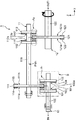
図1に示すように、動力伝達装置1は、3つのロータ10,11,12を備える。ロータ10は、X軸方向に延びる回転軸100と、回転軸100に固定され、X軸方向に直交する平面方向を径方向とする2枚のロータディスク101,102を有する。これらロータディスク101,102は、X軸方向からの平面視で円盤形状を有する。また、ロータ10には、ロータディスク101のX軸方向右側の主面101aにおける外縁部に配置された複数の磁石103、およびロータディスク102のX軸方向左側の主面102aにおける外縁部に配置された複数の磁石104を有する。
As shown in FIG. 1, the power transmission device 1 includes three
ロータ11は、X軸方向に延び、ロータ10の回転軸100に対してZ軸方向に間隔をあけて配置された回転軸110を有する。回転軸110には、X軸方向に直交する平面方向を径方向とする3枚のロータディスク111,112,113が固定されている。これらのロータディスク111,112,113についても、X軸方向からの平面視で円盤形状を有する。ロータディスク111は、回転軸110に対して、X軸方向左側で固定されており、X軸方向における、ロータ10のロータディスク101とロータディスク102との間に挟まれる位置に配置されている。
The
一方、ロータディスク112は、回転軸110に対して、ロータディスク111からX軸方向右側に間隔をあけた位置に固定され、ロータディスク113は、ロータディスク112からさらにX軸方向右側に間隔をあけた位置に固定されている。
On the other hand, the
また、ロータ11には、ロータディスク111のX軸方向左側の主面111aにおける外縁部に配置された複数の磁石114、およびロータディスク111のX軸方向右側の主面111bにおける外縁部に配置された複数の磁石115、およびロータディスク112のX軸方向右側の主面112aにおける外縁部に配置された複数の磁石116、およびロータディスク113のX軸方向左側の主面113aにおける外縁部に配置された複数の磁石117を有する。
The
ロータ12は、X軸方向に延び、ロータ11の回転軸110に対してZ軸方向に間隔をあけ、ロータ10の回転軸100に対してX軸方向に間隔をあけて配置された回転軸120を有する。回転軸120には、X軸方向に直交する平面方向を径方向とするロータディスク121が固定されている。ロータディスク121についても、X軸方向からの平面視で円盤形状を有する。ロータディスク121は、回転軸120に対して、X軸方向における、ロータ11のロータディスク112とロータディスク113との間に挟まれる位置に配置されている。
The
また、ロータ12には、ロータディスク121のX軸方向右側の主面121aにおける外縁部に配置された複数の磁石122、およびロータディスク121のX軸方向左側の主面121bにおける外縁部に配置された複数の磁石123を有する。
The
ここで、複数の磁石103,104,114,115,116,117,122,123については、各ロータディスク101,102,111,112,113,121をX軸方向から平面視する場合に、それぞれ円環状に配置されている(図1では、一部の磁石のみを簡略的に図示)。
Here, regarding the plurality of
ロータディスク111の主面111aに配置された複数の磁石114の一部は、二点鎖線で囲んで示す領域A1において、ロータディスク101に配置された複数の磁石103の一部に対して、X軸方向に間隔をあけた状態で対向する。また、ロータディスク111の主面111bに配置された複数の磁石115の一部は、領域A1において、ロータディスク102に配置された複数の磁石104の一部に対して、X軸方向に間隔をあけた状態で対向する。
Some of the plurality of
ここで、領域A1において、対向する磁石114と磁石103は、一方がS極であって、他方がN極である。同様に、領域A1において、対向する磁石115と磁石104は、一方がS極であって、他方がN極である。また、ロータディスク111をその厚み方向に挟んでX軸方向に背中合わせに配置された磁石114と磁石115とは、一方がS極であって、他方がN極である。
Here, in the region A1, one of the opposing
ロータディスク121に配置された複数の磁石122の一部は、二点鎖線で囲んで示す領域A2において、ロータディスク112に配置された複数の磁石116の一部に対して、X軸方向に間隔をあけた状態で対向する。同様に、ロータディスク121に配置された複数の磁石123の一部は、領域A2において、ロータディスク113に配置された複数の磁石117の一部に対して、X軸方向に間隔をあけた状態で対向する。
Some of the plurality of
ここで、領域A2においても、対向する磁石122と磁石116は、一方がS極であって、他方がN極である。同様に、領域A2において、対向する磁石123と磁石117は、一方がS極であって、他方がN極である。また、ロータディスク121をその厚み方向挟んでX軸方向に背中合わせに配置された磁石122と磁石123とは、一方がS極であって、他方がN極である。
Here, even in a region A 2, magnet 122 and the magnet 116 opposite to it one of a S pole, and the other is N pole. Similarly, in the region A 2 , one of the opposing
動力伝達装置1は、上記の構成を有することで、動力伝達経路PW1が形成され、磁気歯車を用いた非接触型の減速機として機能する。例えば、ロータ10の回転軸100に回転駆動力が入力された場合(IN1)、ロータ11の回転軸110に対して低速回転化・高トルク化されて動力伝達され、さらに、ロータ12の回転軸120に対して、低速回転化・高トルク化されて出力される(OUT1)。一例として、ロータ10の回転軸100の回転数と、ロータ11の回転軸110の回転数と、ロータ12の回転軸120の回転数の比は、100000rpm:10000rpm:1000rpmである。
Since the power transmission device 1 has the above-described configuration, the power transmission path PW 1 is formed and functions as a non-contact type speed reducer using a magnetic gear. For example, when a rotational driving force is input to the
なお、動力伝達装置1において、回転駆動力の入力と出力を入れ替えると、増速機として機能することになる。 In the power transmission device 1, when the input and output of the rotational driving force are switched, the power transmission device 1 functions as a speed increaser.
2.ロータディスク101,102,111,112,113,121に対する磁石103,104,114,115,116,117,122,123の配置形態
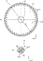
ロータディスク111,121に対する磁石114,115,122,123の配置形態について、図2(a)を用い説明する。なお、図2(a)では、ロータディスク111の主面111aに対する磁石114の配置形態だけを図示しているが、ロータディスク111の主面111bに対する磁石115の配置形態、ロータディスク121の主面121a,121bに対する磁石122,123の各配置形態についても同様である。
2. Arrangement form of
図2(a)に示すように、平面視円盤形状のロータディスク111に対しては、主面111aの外縁部に複数の磁石114が配置されている。複数の磁石114は、周方向にS極・N極が交互に並んでおり、全体として平面視円環状の配置形態をなしている。
As shown in FIG. 2A, a plurality of
なお、本実施形態では、一例として40極の構成としている。また、本実施形態では、ロータディスク111の最外縁部に複数の磁石114を配置することとしているが、必ずしもこれに限定されるものではない。
In the present embodiment, a 40-pole configuration is used as an example. In the present embodiment, the plurality of
次に、ロータディスク101,102,112,113に対する磁石103,104,116,117の配置形態について、図2(b)を用い説明する。なお、図2(b)では、ロータディスク101の主面101aに対する磁石103の配置形態だけを図示しているが、ロータディスク102の主面102aに対する磁石104の配置形態、ロータディスク112の主面112aに対する磁石116の配置形態、およびロータディスク113の主面113aに対する配置形態についても同様である。
Next, the arrangement of the
図2(b)に示すように、小径の平面視円盤形状のロータディスク101に対しても、主面101aの外縁部に複数の磁石103が配置されている。複数の磁石103は、周方向にS極・N極が交互に並んでおり、全体として平面視円環状の配置形態をなしている。本実施形態では、一例として4極の構成としているが、6極あるいは8極とすることもできる。これは、減速比との関係に基づいて設定することができる。
As shown in FIG. 2B, a plurality of
また、小径のロータディスク103に対しても、その最外縁部に複数の磁石103を配置することとしているが、必ずしもこれに限定されるものではない。
Further, although the plurality of
図2(a)、(b)に示すように、減速機としての動力伝達装置1では、領域A1における動力伝達経路PW1(図1を参照。)における下流側のロータディスク101への複数の磁石103の配置に係るピッチ円直径(P.C.D)D103に対して、上流側のロータディスク111への複数の磁石114の配置に係るピッチ円直径(P.C.D)D114が大きい。減速比については、ピッチ円直径D103および磁石103の数(極数)と、ピッチ円直径D114および磁石114の数(極数)との比により規定することができる。
As shown in FIGS. 2A and 2B, in the power transmission device 1 as a speed reducer, a plurality of power transmission paths PW 1 (see FIG. 1) in the region A 1 to the
3.領域A1,A2およびその周辺領域での磁束の流れ
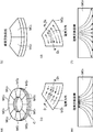
本実施の形態に係る動力伝達装置1では、回転軸100,110,120、およびロータディスク101,102,111,112,113,121が、磁性材料から構成されている。これにより、図3の破線で囲んで示すように、領域A1,A2およびその周辺領域での磁束の流れMF1を形成することができる。なお、図3では、領域A1での磁束の流れMF1だけを図示しているが、領域A2についても同様に磁束の流れを形成することができる。
3. In the power transmission device 1 according to the present embodiment, the
さらに、図3に示すように、動力伝達装置1において、磁石114と磁石103との磁石対向面積、および磁石115と磁石104との磁石対向面積をSOPとする。ロータディスク101の内部磁路面積をS101とし、ロータディスク102の内部磁路面積をS102とする。そして、回転軸100におけるX軸方向に直交する平面方向での断面積をS100とするとき、本実施形態では、SOPに対して、S101、S102およびS100が同等以上である。
Furthermore, as shown in FIG. 3, the power transmission apparatus 1, the magnet opposing area between the
このように規定することにより、領域A1およびその周辺領域での磁束漏れを少なくすることができる。これにより、伝達効率の向上を図ることができるとともに、大きなトルクの動力を伝達することができる。 By defining in this way, it is possible to reduce the magnetic flux leakage in the region A 1 and the peripheral region thereof. As a result, the transmission efficiency can be improved and a large torque power can be transmitted.
4.極異方性磁石の採用
本実施形態に係る動力伝達装置1では、磁石103,104,114,115,116,117,122,123に等方性磁石を採用することもできるが、極異方性磁石を採用することが好ましい。これについて、図4および図5を用い説明する。
4). Adoption of Polar Anisotropic Magnet In the power transmission device 1 according to the present embodiment, an isotropic magnet can be adopted for the
図4(a)に示すように、ロータディスクの外縁部に、その周方向に磁石MG1と磁石MG2とが交互に配置された状態を仮定する。磁石MG1および磁石MG2は、ともに極異方性磁石であって、一方がS極、他方がN極である。図4(b)は、図4(a)のC部分を拡大した図であり、紙面手前側が磁束交換面側である。 As shown in FIG. 4 (a), the outer edge of the rotor disk, it is assumed a state in which the magnet MG 1 and the magnet MG 2 are arranged alternately in the circumferential direction. Magnet MG 1 and the magnet MG 2 are both a polar anisotropic magnet, which is one S pole, and the other N-pole. FIG. 4B is an enlarged view of a portion C in FIG. 4A, and the front side of the drawing is the magnetic flux exchange surface side.
図4(c)に示すように、磁石MG1では、平面視において、磁束方向が円弧の内側を向き、図4(d)に示すように、磁石MG2では、平面視において、磁束方向が円弧の外側を向く。 As shown in FIG. 4 (c), the magnet MG 1, in plan view, magnetic flux direction faces the inside of the arc, as shown in FIG. 4 (d), the magnet MG 2, in plan view, the magnetic flux direction Look outside the arc.
図4(c)のD1−D1断面を示す図4(e)には、磁束が磁束交換面側に向けて収束する方向に向くことがわかる。一方、図4(d)のD2−D2断面を示す図4(f)では、磁束が磁束交換面側から反対側の面に向けて発散する方向に向くことがわかる。 Figure 4 (e) showing the D 1 -D 1 section of FIG. 4 (c), it can be seen that point toward which the magnetic flux converges toward the flux exchange surface. On the other hand, in FIG. 4 (f) showing the D 2 -D 2 cross section of FIG. 4 (d), it can be seen that the magnetic flux is directed in a direction to diverge from the magnetic flux exchange surface side toward the opposite surface.
次に、図5(a)に示すように、極異方性磁石を採用する場合には、磁力線は磁石表面側で密度が高くなり、大きな磁力が得られることがわかる。 Next, as shown in FIG. 5 (a), when a polar anisotropic magnet is employed, the magnetic lines of force increase in density on the magnet surface side, and a large magnetic force can be obtained.
一方、図5(b)に示すように、等方性磁石を採用する場合には、極異方性磁石を採用する場合に比べて、磁石表面側での磁力線の密度が低く、相対的に低い磁力しか得られないことがわかる。 On the other hand, as shown in FIG. 5B, when an isotropic magnet is employed, the density of magnetic lines of force on the magnet surface side is lower than when a polar anisotropic magnet is employed. It can be seen that only a low magnetic force can be obtained.
以上より分かるように、本実施形態に係る動力伝達装置1では、極異方性磁石からなる磁石103,104,114,115,116,117,122,123を採用することにより、N極とS極の境界近辺の磁束交換面側での磁束の流れがより滑らかであり、各極の中心付近でより大きな磁束の流れが形成される。よって、動力伝達装置1は、等方性磁石を採用する場合に比べて、高効率かつ高トルクに動力伝達を行うことができる。
As can be seen from the above, in the power transmission device 1 according to the present embodiment, the
5.優位性
本実施形態に係る動力伝達装置1では、X軸方向において、ロータ11のロータディスク111が、ロータ10のロータディスク101,103の間に配置されている。そして、領域A1において、ロータディスク111の主面111aに配置された複数の磁石114の一部と、ロータディスク101の主面101aに配置された複数の磁石103の一部とが間隔をあけて対向し、当該対向部分で磁力が作用する。同様に、ロータディスク111の主面111bに配置された複数の磁石115の一部と、ロータディスク102の主面102aに配置された複数の磁石104の一部とが間隔をあけて対向し、当該対向部分でも磁力が作用する。
5. Superiority In the power transmission device 1 according to the present embodiment, the
このような構成を採用する動力伝達装置1では、ロータ10およびロータ11の回転時において、ロータディスク101の磁石103と、ロータディスク111の対向する磁石114とが引き合う力と、ロータディスク102の磁石104と、ロータディスク111の対向する磁石115とが引き合う力とが、互いに相殺する関係の向きに作用する。よって、動力伝達装置1では、回転軸100および回転軸110にかかるX軸方向の力の相殺を図ることができる。ロータ11とロータ12との間での動力伝達においても、同様に、回転軸110および回転軸120にかかるX軸方向の力の相殺を図ることができる。なお、このような軸方向に働く力の相殺により、図示を省略している軸受けなどへの負荷も低減することができる。
In the power transmission device 1 adopting such a configuration, when the
また、動力伝達装置1は、磁気歯車を用いた非接触型の動力伝達装置であるので、直接的・物理的に接触する歯車を用いた動力伝達装置よりも、伝達ロスの低減を図ることができる。特に、入力回転数が超高回転(例えば、100000rpm以上)の場合などには、高い伝達効率の実現という観点から好適である。 Further, since the power transmission device 1 is a non-contact power transmission device using magnetic gears, transmission loss can be reduced as compared with a power transmission device using gears that are in direct and physical contact. it can. In particular, when the input rotational speed is an extremely high rotation (for example, 100000 rpm or more), it is preferable from the viewpoint of realizing high transmission efficiency.
以上のように、本実施形態に係る動力伝達装置1は、伝達ロスの低減を図ることができるとともに、高い信頼性を実現することができる。 As described above, the power transmission device 1 according to the present embodiment can reduce transmission loss and achieve high reliability.
さらに、本実施形態に係る動力伝達装置1では、1枚の大径のロータディスク111のX軸方向両側に2枚の小径のロータディスク101,102を配置し、1枚の大径のロータディスク121のX軸方向両側に2枚の小径のロータディスク112,113を配置しているので、軽量化を図ることができる。即ち、1枚の大径ロータディスクと2枚の小径ロータディスクとの組み合わせで動力伝達することとしているので、仮に、1枚の小径ロータディスクと2枚の大径ロータディスクとの組み合わせとする場合に比べて、ロータディスクのトータルでの重量低減を図ることができる。
Furthermore, in the power transmission device 1 according to the present embodiment, two small-
[第2実施形態]
1.全体構成
本発明の第2実施形態に係る動力伝達装置2の全体構成について、図6を用い説明する。なお、図6でも、骨子となる部材のみを抽出して図示しており、その他の部材(例えば、軸受などの部材)の図示を省略している。また、上記第1実施形態と同一の構成については、説明を省略する。
[Second Embodiment]
1. Overall Configuration The overall configuration of the
図6に示すように、動力伝達装置2についても、3つのロータ20,21,22を備える。ロータ20は、X軸方向に延びる回転軸200と、回転軸200に固定され、X軸方向に直交する平面方向を径方向とするロータディスク201を有する。ロータディスク201も、X軸方向からの平面視で円盤形状を有する。また、ロータ20には、ロータディスク201の一方の主面201aにおける外縁部に配置された複数の磁石202、およびロータディスク201の他方の主面201bにおける外縁部に配置された複数の磁石203を有する。
As shown in FIG. 6, the
ロータ21は、X軸方向に延び、ロータ20の回転軸200に対してZ軸方向に間隔をあけて配置された回転軸210を有する。回転軸210には、X軸方向に直交する平面方向を径方向とする3枚のロータディスク211,212,213が固定されている。これらのロータディスク211,212,213についても、X軸方向からの平面視で円盤形状を有する。ロータディスク211は、回転軸210に対して、X軸方向左側で固定されており、X軸方向における、ロータ20のロータディスク201に対し間隔をあけて左側に隣接する位置に配置されている。
The
ロータディスク212は、回転軸210に対して、ロータディスク211よりもX軸方向右側の位置で固定されており、X軸方向における、ロータ20のロータディスク201に対し間隔をあけて右側に隣接する位置に配置されている。ロータ20のロータディスク201は、その外周部の一部が、ロータ21のロータディスク211とロータディスク212との間に配置されることになる。
The
一方、ロータディスク213は、回転軸210に対して、ロータディスク212からX軸方向右側に間隔をあけた位置に固定されている。
On the other hand, the
また、ロータ21には、ロータディスク211のX軸方向右側の主面211aにおける外縁部に配置された複数の磁石214、およびロータディスク212のX軸方向左側の主面212aにおける外縁部に配置された複数の磁石215、およびロータディスク213のX軸方向左側の主面213aaにおける外縁部に配置された複数の磁石216、およびロータディスク213のX軸方向右側の主面213bにおける外縁部に配置された複数の磁石217を有する。
The
ロータ22は、X軸方向に延び、ロータ21の回転軸210に対してZ軸方向に間隔をあけ、ロータ20の回転軸200に対してX軸方向に間隔をあけて配置された回転軸220を有する。回転軸220には、X軸方向に直交する平面方向を径方向とし、互いにX軸方向に間隔をあけて配置されるロータディスク221,222が固定されている。ロータディスク221,222についても、X軸方向からの平面視で円盤形状を有する。ロータディスク221は、回転軸220に対して、X軸方向における、ロータ21のロータディスク213に対し間隔をあけて左側に隣接する位置に配置されている。ロータディスク222は、回転軸220に対して、X軸方向における、ロータ21のロータディスク213に対し間隔をあけて右側に隣接する位置に配置されている。
The
また、ロータ22には、ロータディスク221のX軸方向右側の主面221aにおける外縁部に配置された複数の磁石223、およびロータディスク222のX軸方向左側の主面222aにおける外縁部に配置された複数の磁石224を有する。
The
ここで、本実施の形態においても、複数の磁石202,203,214,215,216,217,223,224については、各ロータディスク201,211,212,213,221,222をX軸方向から平面視する場合に、それぞれ円環状に配置されている(図2を参照)。
Here, also in the present embodiment, for the plurality of
ロータディスク201の主面201aに配置された複数の磁石202の一部は、二点鎖線で囲んで示す領域E1において、ロータディスク211に配置された複数の磁石214の一部に対して、X軸方向に間隔をあけた状態で対向する。また、ロータディスク201の主面201bに配置された複数の磁石203の一部は、領域E1において、ロータディスク212に配置された複数の磁石215の一部に対して、X軸方向に間隔をあけた状態で対向する。
Some of the plurality of
ここで、領域E1において、対向する磁石202と磁石214は、一方がS極であって、他方がN極である。同様に、領域E1において、対向する磁石203と磁石215は、一方がS極であって、他方がN極である。また、ロータディスク201をその厚み方向に挟んでX軸方向に背中合わせに配置された磁石202と磁石203とは、一方がS極であって、他方がN極である。
Here, in the region E1, one of the opposing
ロータディスク221に配置された複数の磁石223の一部は、二点鎖線で囲んで示す領域E2において、ロータディスク213の主面213aに配置された複数の磁石216の一部に対して、X軸方向に間隔をあけた状態で対向する。同様に、ロータディスク222に配置された複数の磁石224の一部は、領域E2において、ロータディスク213の主面213bに配置された複数の磁石217の一部に対して、X軸方向に間隔をあけた状態で対向する。
Some of the plurality of
ここで、領域E2においても、対向する磁石223と磁石216は、一方がS極であって、他方がN極である。同様に、領域E2において、対向する磁石224と磁石217は、一方がS極であって、他方がN極である。また、ロータディスク213をその厚み方向挟んでX軸方向に背中合わせに配置された磁石216と磁石217とは、一方がS極であって、他方がN極である。
Here, even in a region E 2, magnet 223 and the
動力伝達装置2についても、上記の構成を有することで、動力伝達経路PW2が形成され、磁気歯車を用いた非接触型の減速機として機能する。例えば、ロータ20に回転駆動力が入力された場合(IN2)、ロータ21に対して低速回転化・高トルク化されて動力伝達され、さらに、ロータ22に対して、低速回転化・高トルク化されて出力される(OUT2)。本実施形態に係る動力伝達装置2においても、回転駆動力の入力と出力を入れ替えると、増速機として機能することになる。
The
2.優位性
本実施形態に係る動力伝達装置2でも、ロータ20およびロータ21の回転時において、ロータディスク201の磁石202と、ロータディスク211の対向する磁石214とが引き合う力と、ロータディスク201の磁石203と、ロータディスク212の対向する磁石215とが引き合う力とが、互いに相殺する関係の向きに作用する。よって、動力伝達装置2でも、回転軸200および回転軸210にかかるX軸方向の力の相殺を図ることができる。ロータ21とロータ22との間での動力伝達においても、同様に、回転軸210および回転軸220にかかるX軸方向の力の相殺を図ることができる。なお、このような軸方向に働く力の相殺により、図示を省略している軸受けなどへの負荷も低減することができる。
2. Advantages Also in the
また、動力伝達装置2についても、磁気歯車を用いた非接触型の動力伝達装置であるので、直接的・物理的に接触する歯車を用いた動力伝達装置よりも、伝達ロスの低減を図ることができる。
Further, since the
以上より、本実施形態に係る動力伝達装置2でも、伝達ロスの低減を図ることができるとともに、高い信頼性を実現することができる。
As described above, also in the
[第3実施形態]
1.構成
本実施形態に係る動力伝達装置3の全体構成について、図7を用い説明する。なお、図7においても、骨子となる部材のみを抽出して図示しており、その他の部材(例えば、軸受などの部材)の図示を省略している。
[Third Embodiment]
1. Configuration The overall configuration of the power transmission device 3 according to the present embodiment will be described with reference to FIG. In FIG. 7, only the members that are the main points are extracted and illustrated, and other members (for example, members such as bearings) are not illustrated.
図7に示すように、動力伝達装置3は、4つのロータ30,31,32,33を備える。ロータ30は、X軸方向に延びる回転軸300と、回転軸300に固定され、X軸方向に直交する平面方向を径方向とする2枚のロータディスク301,302を有する。これらロータディスク301,302も、上記第1実施形態および第2実施形態などと同様に、X軸方向からの平面視で円盤形状を有する。
As shown in FIG. 7, the power transmission device 3 includes four
また、ロータ30には、ロータディスク301のX軸方向右側の主面301aにおける外縁部に配置された複数の磁石303、およびロータディスク302のX軸方向左側の主面302aにおける外縁部に配置された複数の磁石304を有する。
In addition, the
ロータ31は、X軸方向に延び、ロータ30の回転軸300に対してZ軸方向に間隔をあけて配置された回転軸310を有する。回転軸310には、X軸方向に直交する平面方向を径方向とする3枚のロータディスク311,312,313が固定されている。これらのロータディスク311,312,313についても、X軸方向からの平面視で円盤形状を有する。ロータディスク311は、回転軸310に対して、X軸方向左側で固定されており、X軸方向における、ロータ30のロータディスク301とロータディスク302との間に挟まれる位置に配置されている。
The
一方、ロータディスク312は、回転軸310に対して、ロータディスク311からX軸方向右側に間隔をあけた位置に固定され、ロータディスク313は、ロータディスク312からさらにX軸方向右側に間隔をあけた位置に固定されている。
On the other hand, the
また、ロータ31には、ロータディスク311の一方の主面311aにおける外縁部に配置された複数の磁石314、およびロータディスク311の他方の主面311bにおける外縁部に配置された複数の磁石315、およびロータディスク312の主面312aにおける外縁部に配置された複数の磁石316、およびロータディスク313の主面313aにおける外縁部に配置された複数の磁石317を有する。
In addition, the
ロータ32は、X軸方向に延び、ロータ30の回転軸300およびロータ31の回転軸310の双方に対してZ軸方向に間隔をあけて配置された回転軸320を有する。回転軸320には、X軸方向に直交する平面方向を径方向とする3枚のロータディスク321,322,323が固定されている。これらのロータディスク321,322,323についても、X軸方向からの平面視で円盤形状を有する。ロータディスク321は、回転軸320に対して、X軸方向左側で固定されており、X軸方向における、ロータ30のロータディスク301とロータディスク302との間に挟まれる位置に配置されている。この配置を実現するために、動力伝達装置3では、X軸方向において、ロータ31のロータディスク311とロータ32のロータディスク321とが略同一の位置に配置されている。
The
一方、ロータディスク322は、回転軸320に対して、ロータディスク321からX軸方向右側に間隔をあけた位置に固定され、ロータディスク323は、ロータディスク322からさらにX軸方向右側に間隔をあけた位置に固定されている。
On the other hand, the
また、ロータ32には、ロータディスク321の一方の主面321aにおける外縁部に配置された複数の磁石324、およびロータディスク321の他方の主面321bにおける外縁部に配置された複数の磁石325、およびロータディスク322の主面322aにおける外縁部に配置された複数の磁石326、およびロータディスク323の主面323aにおける外縁部に配置された複数の磁石327を有する。
The
ロータ33は、X軸方向に延び、Z軸方向においてロータ31の回転軸310とロータ32の回転軸320との間に双方の回転軸310,320と間隔をあけ、ロータ30の回転軸300に対してX軸方向に間隔をあけて配置された回転軸330を有する。回転軸330には、X軸方向に直交する平面方向を径方向とするロータディスク331が固定されている。ロータディスク331についても、X軸方向からの平面視で円盤形状を有する。ロータディスク331は、回転軸320に対して、X軸方向における、ロータ31のロータディスク312とロータディスク313との間、およびロータ32のロータディスク322とロータディスク323との間、に挟まれる位置に配置されている。この配置を実現するため、動力伝達装置3では、X軸方向において、ロータ31のロータディスク312とロータ33のロータディスク322とが略同一の位置に配置され、ロータ31のロータディスク313とロータ32のロータディスク323とが略同一の位置に配置されている。
The
また、ロータ33には、ロータディスク331の一方の主面331aにおける外縁部に配置された複数の磁石332、およびロータディスク331の他方の主面331bにおける外縁部に配置された複数の磁石333を有する。
Further, the
ここで、複数の磁石303,304,314,315,316,317,324,325,326,327,332,333については、各ロータディスク301,302,311,312,313,321,322,323,331をX軸方向から平面視する場合に、それぞれ円環状に配置されている(図7でも、一部の磁石のみを簡略的に図示)。
Here, with respect to the plurality of
ロータディスク311の主面311aに配置された複数の磁石314の一部は、二点鎖線で囲んで示す領域F1において、ロータディスク301に配置された複数の磁石303の一部に対して、X軸方向に間隔をあけた状態で対向する。また、ロータディスク311の主面311bに配置された複数の磁石315の一部は、領域F1において、ロータディスク302に配置された複数の磁石304の一部に対して、X軸方向に間隔をあけた状態で対向する。
Some of the plurality of
ここで、領域F1において、対向する磁石314と磁石303は、一方がS極であって、他方がN極である。同様に、領域F1において、対向する磁石315と磁石304は、一方がS極であって、他方がN極である。また、ロータディスク311をその厚み方向に挟んでX軸方向に背中合わせに配置された磁石314と磁石315とは、一方がS極であって、他方がN極である。
Here, in the region F 1 , one of the opposing
ロータディスク321の主面321aに配置された複数の磁石324の一部は、二点鎖線で囲んで示す領域F2において、ロータディスク301に配置された複数の磁石303の一部に対して、X軸方向に間隔をあけた状態で対向する。また、ロータディスク321の主面321bに配置された複数の磁石325の一部は、領域F2において、ロータディスク302に配置された複数の磁石304の一部に対して、X軸方向に間隔をあけた状態で対向する。
Some of the plurality of
ここで、領域F2において、対向する磁石324と磁石303は、一方がS極であって、他方がN極である。同様に、領域F2において、対向する磁石325と磁石304は、一方がS極であって、他方がN極である。また、ロータディスク321をその厚み方向に挟んでX軸方向に背中合わせに配置された磁石324と磁石325とは、一方がS極であって、他方がN極である。
Here, in the area F 2, magnet 324 and the
ロータディスク331に配置された複数の磁石332の一部は、二点鎖線で囲んで示す領域F3において、ロータディスク312に配置された複数の磁石316の一部に対して、X軸方向に間隔をあけた状態で対向する。同様に、ロータディスク331に配置された複数の磁石333の一部は、領域F3において、ロータディスク313に配置された複数の磁石317の一部に対して、X軸方向に間隔をあけた状態で対向する。
Some of the plurality of
ここで、領域F3においても、対向する磁石332と磁石316は、一方がS極であって、他方がN極である。同様に、領域F3において、対向する磁石333と磁石317は、一方がS極であって、他方がN極である。また、ロータディスク331をその厚み方向挟んでX軸方向に背中合わせに配置された磁石332と磁石333とは、一方がS極であって、他方がN極である。
Here, also in the region F 3 , one of the opposing
また、ロータディスク331に配置された複数の磁石332の一部は、二点鎖線で囲んで示す領域F4において、ロータディスク322に配置された複数の磁石326の一部に対して、X軸方向に間隔をあけた状態で対向する。同様に、ロータディスク331に配置された複数の磁石333の一部は、領域F4において、ロータディスク323に配置された複数の磁石327の一部に対して、X軸方向に間隔をあけた状態で対向する。
Also, some of the plurality of
ここで、領域F4においても、対向する磁石332と磁石326は、一方がS極であって、他方がN極である。同様に、領域F4において、対向する磁石333と磁石327は、一方がS極であって、他方がN極である。
Here, even in a region F 4, the
動力伝達装置3は、上記の構成を有することで、動力伝達経路PW30が、動力伝達経路PW31と動力伝達経路PW32に一旦分割され、ロータ33で動力伝達経路PW33に統合される。そして、本実施形態に係る動力伝達装置3も、磁気歯車を用いた非接触型の減速機として機能する。例えば、ロータ30に回転駆動力が入力された場合(IN3)、ロータ31およびロータ32に対して低速回転化・高トルク化されて動力伝達され、さらに、ロータ33に対して、低速回転化・高トルク化されて出力される(OUT3)。
Since the power transmission device 3 has the above-described configuration, the power transmission path PW 30 is once divided into a power transmission path PW 31 and a power transmission path PW 32 , and is integrated into the power transmission path PW 33 by the
なお、動力伝達装置3においても、回転駆動力の入力と出力を入れ替えると、増速機として機能することになる。 Note that the power transmission device 3 also functions as a speed increaser if the input and output of the rotational driving force are switched.
2.優位性
本実施形態に係る動力伝達装置3では、ロータ30の回転軸300の回転駆動力が、一旦、ロータ31の回転軸310とロータ32の回転軸320とに分割された状態で実行され(動力伝達経路PW31と動力伝達経路PW32に分割)、再度、ロータ33の回転軸330で統合される(動力伝達経路PW33に統合)。よって、上記第1実施形態と同様の優位性を有するとともに、高トルクの伝達にさらに優位である。また、ロータ30およびロータ33に対する、ロータ31およびロータ32の配置により、対称的な配置とすることができ、動力伝達に起因する装置全体での不所望なモーメントの発生を抑制することもできる。
2. Superiority In the power transmission device 3 according to the present embodiment, the rotational driving force of the
なお、動力伝達装置3において、回転駆動力の入力と出力を入れ替え、増速機として用いる場合にあっても、その動力伝達経路の途中で、一旦、ロータ31の回転軸310とロータ32の回転軸320とに分割されることは同様である。この場合にも、上記同様の優位性が得られる。
In the power transmission device 3, even when the input and output of the rotational driving force are switched and used as a speed increaser, the rotation of the
[小径のロータディスクへの磁石の配置数についての考察]
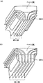
上記第1実施形態、第2実施形態および第3実施形態では、小径のロータディスク101,102,112,113,201,213,301,302,312,313,322,323へ配置の磁石数を、一例としてS極が2つ、N極が2つの合計4つ、即ち、4極としている。上述のように、6極とすることや8極とすることも可能であるが、2極とすることは高信頼性を実現する上で好ましくない。これについて、図8を用い説明する。
[Consideration on the number of magnets arranged on a small-diameter rotor disk]
In the first embodiment, the second embodiment, and the third embodiment, the number of magnets arranged in the small-
先ず、4極構成のロータディスクを採用する場合について説明する。 First, a case where a four-pole rotor disk is employed will be described.
図8(a)に示すように、小径ロータディスクRD2がある位相状態にあるとき、そのN極磁石MGN2は、大径ロータディスクRD1のS極磁石MGS1と紙面垂直方向に対向する。この位相状態では、大径ロータディスクRD1のN極磁石MGN1は、小径ロータディスクRD2のN極磁石MGN2とは対向していない状態となっている。 As shown in FIG. 8A, when the small-diameter rotor disk RD 2 is in a certain phase state, the N-pole magnet MG N2 faces the S-pole magnet MG S1 of the large-diameter rotor disk RD 1 in the direction perpendicular to the paper surface. . In this phase state, the N-pole magnet MG N1 of the large-diameter rotor disk RD 1 is not in opposition to the N-pole magnet MG N2 of the small-diameter rotor disk RD 2 .
小径ロータディスクRD2を45°左回転させると、大径ロータディスクRD1が所定角度だけ連動して回転する。回転後の状態を示すのが図8(b)である。図8(b)に示すように、小径ロータディスクRD2が45°回転し終わった状態では、大径ロータディスクRD1との対向領域における中間部分に、N極磁石MGN2とS極磁石MGS2との境界が存在することになる。これに対して、大径ロータディスクRD1も同期して回転しているため、小径ロータディスクRD2のN極磁石MGN2には大径ロータディスクRD1のS極磁石MGS1が対向し、小径ロータディスクRD2のS極磁石MGS2には大径ロータディスクRD1のN極磁石MGN1が対向した状態となる。 When the small-diameter rotor disc RD 2 to 45 ° rotated left, the large-diameter rotor disc RD 1 is rotated in conjunction predetermined angle. FIG. 8B shows the state after rotation. As shown in FIG. 8B, in a state where the small-diameter rotor disk RD 2 has been rotated by 45 °, an N-pole magnet MG N2 and an S-pole magnet MG are provided in the middle portion in the region facing the large-diameter rotor disk RD 1. A boundary with S2 exists. On the other hand, since the large-diameter rotor disk RD 1 is also rotating in synchronization, the S-pole magnet MG S1 of the large-diameter rotor disk RD 1 faces the N-pole magnet MG N2 of the small-diameter rotor disk RD 2 . The N-pole magnet MG N1 of the large-diameter rotor disk RD 1 is opposed to the S-pole magnet MG S2 of the small-diameter rotor disk RD 2 .
以上より、小径ロータディスクRD2を4極構成とする場合には、小径ロータディスクRD2の磁石MGS2、MGN2を広い面積で使用することができ、かつ、大径ロータディスクRD1との間で磁石の同極同士が対向する部分の面積を小さくすることができる。よって、対向領域における負の力を小さくすることができ、大きなトルク伝達に好適である。 As described above, when the small-diameter rotor disk RD 2 has a four-pole configuration, the magnets MG S2 and MG N2 of the small-diameter rotor disk RD 2 can be used in a wide area, and with the large-diameter rotor disk RD 1 The area of the portion where the same poles of the magnets face each other can be reduced. Therefore, the negative force in the facing region can be reduced, which is suitable for large torque transmission.
次に、2極構成のロータディスクを採用する場合について説明する。 Next, a case where a two-pole rotor disk is employed will be described.
図8(c)に示すように、小径ロータディスクRD3が所定の位相状態にあるとき、そのN極磁石MGN4は、大径ロータディスクRD3のS極磁石MGS3と紙面垂直方向に対向する。この位相状態では、大径ロータディスクRD3のN極磁石MGN3は、小径ロータディスクRD4のN極磁石MGN4とは対向していない状態となっている。 As shown in FIG. 8C, when the small-diameter rotor disk RD 3 is in a predetermined phase state, the N-pole magnet MG N4 faces the S-pole magnet MG S3 of the large-diameter rotor disk RD 3 in the direction perpendicular to the paper surface. To do. In this phase state, the N-pole magnet MG N3 of the large-diameter rotor disk RD 3 is not in opposition to the N-pole magnet MG N4 of the small-diameter rotor disk RD 4 .
小径ロータディスクRD4を45°左回転させると、大径ロータディスクRD3が所定角度だけ連動して回転する。回転後の状態を示すのが図8(d)である。図8(d)に示すように、小径ロータディスクRD4が45°回転し終わった状態では、大径ロータディスクRD3との対向領域において、破線で示す箇所に、N極磁石MGN4とS極磁石MGS4との境界が存在することになる。これに対して、大径ロータディスクRD3も所定の角度だけ回転しているため、小径ロータディスクRD4のN極磁石MGN4の一部に対し、大径ロータディスクRD3のN極磁石MGN3の一部が対向した状態となる。これにより、N極磁石MGN4の一部とN極磁石MGN3の一部が対向する領域では、互いに反発する力が働くことになる。 When the small-diameter rotor disk RD 4 is rotated 45 degrees counterclockwise, the large-diameter rotor disk RD 3 rotates in conjunction with a predetermined angle. FIG. 8D shows the state after rotation. As shown in FIG. 8D, when the small-diameter rotor disk RD 4 has been rotated by 45 °, the N-pole magnets MG N4 and S are located at the positions indicated by the broken lines in the region facing the large-diameter rotor disk RD 3. A boundary with the polar magnet MG S4 exists. On the other hand, since the large-diameter rotor disk RD 3 is also rotated by a predetermined angle, the N-pole magnet MG of the large-diameter rotor disk RD 3 is compared with a part of the N-pole magnet MG N4 of the small-diameter rotor disk RD 4. A part of N3 faces each other. Thereby, in the area | region where a part of N-pole magnet MG N4 and a part of N-pole magnet MG N3 oppose, the force which mutually repels will work.
以上より、2極構成の小径ロータディスクRD4を採用する場合には、回転位相によって小径ロータディスクRD4と大径ロータディスクRD3との間で、引き合う力と反発する力とが交互に作用することになる。よって、高い信頼性を実現する上では望ましくない。 As described above, when the small-diameter rotor disk RD 4 having the two-pole configuration is adopted, the attractive force and the repulsive force alternately act between the small-diameter rotor disk RD 4 and the large-diameter rotor disk RD 3 depending on the rotational phase. Will do. Therefore, it is not desirable for realizing high reliability.
なお、図8(a)、(b)では、4極構成の小径ロータディスクRD2を採用したが、6極構成および8極構成でも、高い信頼性を実現することができる。 Incidentally, FIG. 8 (a), the (b), the is adopted small rotor disc RD 2 of 4 pole configuration, in 6 pole configuration and 8 pole configuration, it is possible to realize a high reliability.
[第4実施形態]
第4実施形態に係る駆動装置5について、図9を用い説明する。
[Fourth Embodiment]
The drive device 5 according to the fourth embodiment will be described with reference to FIG.
図9に示すように、本実施形態に係る駆動装置5は、上記第1実施形態に係る動力伝達装置1と、駆動モータ51と、モータ制御器52と、回転角センサ53とを備える。このうち、動力伝達装置1については、上述の通りであり、ここでの詳細な説明は省略する。 As shown in FIG. 9, the drive device 5 according to the present embodiment includes the power transmission device 1 according to the first embodiment, a drive motor 51, a motor controller 52, and a rotation angle sensor 53. Among these, the power transmission device 1 is as described above, and a detailed description thereof is omitted here.
ただし、動力伝達装置1におけるロータ12の回転軸120に対しては、回転角センサ53が付設されており、回転角信号をモータ制御器52に送出するための信号路S1が設けられている。なお、信号路S1については、有線信号路および無線信号路の何れであってもよい。
However, a rotation angle sensor 53 is attached to the
また、駆動モータ51とモータ制御器52との間には、モータ制御器52から電流制御信号を駆動モータ51に送出するための信号路S2が設けられている。信号路S2についても、有線信号路および無線信号路の何れであってもよい。 A signal path S 2 for sending a current control signal from the motor controller 52 to the drive motor 51 is provided between the drive motor 51 and the motor controller 52. For even signal path S 2, it may be either a wired signal path and a radio signal path.
ここで、駆動モータ51には、例えば、リラクタンスモータが採用されている。 Here, as the drive motor 51, for example, a reluctance motor is employed.
駆動装置5の駆動においては、回転軸120に付設された回転角センサからの回転角情報がモータ制御器52にフィードバックされ、モータ制御器52は、脱調が発生しないように駆動モータ51への電流信号を制御する。
In driving the driving device 5, the rotation angle information from the rotation angle sensor attached to the
本実施形態に係る駆動装置5では、上記第1実施形態に係る動力伝達装置1をそのまま具備しているので、上記効果を奏することができる。なお、動力伝達装置として、上記第2実施形態に係る動力伝達装置2や、上記第3実施形態に係る動力伝達装置3を採用することもできる。また、回転角センサについては、ロータ12の回転軸120に付設するだけでなく、ロータ11の回転軸110に付設することもできるし、回転軸110,120の両方に付設することもできる。また、駆動軸である回転軸100にも付設することとしてもよい。
Since the drive device 5 according to the present embodiment includes the power transmission device 1 according to the first embodiment as it is, the above effect can be achieved. As the power transmission device, the
[変形例]
上記第1実施形態および第2実施形態では、それぞれ3つのロータを構成要素として具備することとし、上記第3実施形態では、4つのロータを構成要素として具備することとしたが、本発明は、これに限定を受けるものではない。例えば、2つのロータからなる動力伝達装置や、5つ以上のロータからなる動力伝達装置などとすることなどが可能である。
[Modification]
In the first embodiment and the second embodiment, each of the three rotors is included as a component, and in the third embodiment, the four rotors are included as a component. This is not a limitation. For example, a power transmission device including two rotors, a power transmission device including five or more rotors, and the like can be used.
また、上記第3実施形態では、動力伝達経路を2分割とする構成を採用したが、本発明は、これに限定を受けるものではない。3つ以上の動力伝達経路に分割することができる。また、上記第3実施形態では、分割した動力伝達経路を、最終的に一つの動力伝達経路に統合することとしたが、必ずしも最終的に一つの動力伝達経路に統合する必要はない。即ち、2系統の出力取り出しの構成を採用することにしてもよい。 Moreover, in the said 3rd Embodiment, although the structure which divides a power transmission path into 2 was employ | adopted, this invention is not limited to this. It can be divided into three or more power transmission paths. In the third embodiment, the divided power transmission paths are finally integrated into one power transmission path, but it is not always necessary to finally integrate them into one power transmission path. That is, you may decide to employ | adopt the structure of the output extraction of two systems.
また、上記第1実施形態から第3実施形態では、1枚のロータディスク111,121,201,213,311,321,331を、2枚のロータディスク101,102,112,113,211,212,221,222,301,302,312,313,322,323で挟み込んだ形態を採用することとしたが、本発明は、これに限定を受けるものではない。例えば、第1ロータに2枚のロータディスクを設け、これに対応する第2ロータに3枚のロータディスクを設けることとしてもよい。この場合、第1ロータの2枚のロータディスクの各間に第2ロータのロータディスクが挿入された形態とすることができる。そして、第1ロータの2枚のロータディスクには、各々の両主面に複数の磁石を配置する。また、第2ロータの端側の2枚のロータディスクには、対向主面側に複数の磁石を配置し、間に配置されるロータディスクには、その両主面に複数の磁石を配置する。これにより、より高トルクの動力伝達が必要な場合にも対応が可能である。そして、組み合わせるロータディスクの枚数については、さらに増やすことも可能である。
In the first to third embodiments, one
また、上記第1実施形態では、一例として、大径のロータディスク111,121を40極とし、小径のロータディスク101,102,112,113を4極としたが、本発明は、これに限定を受けるものではない。大径のロータディスクに配置する磁石の極数と、小径のロータディスクに配置する磁石の極数とは、減速比(増速比)により適宜変更が可能である。
In the first embodiment, as an example, the large-
また、上記第4実施形態では、駆動源の一例としてリラクタンスモータを採用することとしたが、本発明は、これに限定を受けるものではない。例えば、DCモータ、誘導モータ、永久磁石式動機モータ(埋め込み磁石型、表面磁石型)、スイッチトリラクタンスモータ、シンクロナスリラクタンスモータなどを採用することもできる。また、駆動源として、電動モータ以外にも、ガソリンエンジンやディーゼルエンジンなどの内燃機関を採用することもできる。さらに、空圧あるいは油圧のロータリーアクチュエータなどを採用することもできる。 In the fourth embodiment, the reluctance motor is employed as an example of the drive source. However, the present invention is not limited to this. For example, a DC motor, an induction motor, a permanent magnet type motive motor (embedded magnet type, surface magnet type), a switched reluctance motor, a synchronous reluctance motor, or the like may be employed. In addition to the electric motor, an internal combustion engine such as a gasoline engine or a diesel engine can be employed as the drive source. Further, a pneumatic or hydraulic rotary actuator can be employed.
1,2,3 動力伝達装置
5 駆動装置
10−12,20−22,30−33 ロータ
51 駆動モータ
52 モータ制御器
53 回転角センサ
100,110,120、200,210,220,300,310,320,330 回転軸
101−102.111−113,121,201,211−213,221−222,301−302,311−313,321−323,331 ロータディスク
103−104,114−117,122−123,202−203,214−217,223−224,303−304,314−317,324−327,332−333 磁石
1, 2, 3 Power transmission device 5 Drive device 10-12, 20-22, 30-33 Rotor 51 Drive motor 52 Motor controller 53
Claims (9)
前記第1ロータは、
第1方向に延びる第1回転軸と、
前記第1回転軸に固定され、前記第1方向に直交する第2方向を径方向とする第1ロータディスクと、
前記第1ロータディスクの一方の主面の外縁部、および前記第1ロータディスクの他方の主面の外縁部に平面視円環状に配置されてなる複数の第1磁石と、
を有し、
前記第2ロータは、
前記第1方向に延び、かつ、前記第1回転軸に対して前記第2方向に間隔をあけて配置されてなる第2回転軸と、
前記第2回転軸に固定され、前記第2方向を径方向とし、かつ、前記第1ロータディスクと前記第1方向に間隔をあけて配置されてなる第2ロータディスクと、
前記第2回転軸に固定され、前記第2方向を径方向とし、かつ、前記第1方向において前記第1ロータディスクを挟んで前記第2ロータディスクとは反対側に、前記第1ロータディスクと前記第1方向に間隔をあけて配置されてなる第3ロータディスクと、
前記第2ロータディスクにおける前記第1方向の前記第1ロータディスクの側の主面の外縁部に、平面視円環状に配置されてなる複数の第2磁石と、
前記第3ロータディスクにおける前記第1方向の前記第1ロータディスクの側の主面の外縁部に、平面視円環状に配置されてなる複数の第3磁石と、
を有し、
前記複数の第1磁石の一部と、前記複数の第2磁石の一部および前記複数の第3磁石の一部とは、互いに間隔をあけた状態で対向し、
前記第1ロータと前記第2ロータとは、前記複数の第1磁石と、前記複数の第2磁石および前記複数の第3磁石との磁力をもって同期した状態で連動する
ことを特徴とする動力伝達装置。 A power transmission device comprising a first rotor and a second rotor,
The first rotor is
A first rotating shaft extending in a first direction;
A first rotor disk fixed to the first rotating shaft and having a second direction perpendicular to the first direction as a radial direction;
A plurality of first magnets arranged in an annular shape in plan view on an outer edge portion of one main surface of the first rotor disk and an outer edge portion of the other main surface of the first rotor disk;
Have
The second rotor is
A second rotating shaft that extends in the first direction and is spaced from the first rotating shaft in the second direction; and
A second rotor disk fixed to the second rotating shaft, having the second direction as a radial direction, and being spaced apart from the first rotor disk in the first direction;
The first rotor disk is fixed to the second rotating shaft, the second direction is a radial direction, and the first rotor disk is disposed on the opposite side of the first rotor disk in the first direction. A third rotor disk arranged at intervals in the first direction;
A plurality of second magnets arranged in an annular shape in plan view on the outer edge portion of the main surface of the second rotor disk on the first rotor disk side in the first direction;
A plurality of third magnets arranged in an annular shape in plan view on an outer edge portion of the main surface of the third rotor disk on the first rotor disk side in the first direction;
Have
A part of the plurality of first magnets, a part of the plurality of second magnets, and a part of the plurality of third magnets are opposed to each other with a space therebetween,
The first rotor and the second rotor are interlocked in a synchronized state with magnetic forces of the plurality of first magnets, the plurality of second magnets, and the plurality of third magnets. apparatus.
対向する前記第1磁石と前記第2磁石は、一方がS極であって、他方がN極であり、
対向する前記第1磁石と前記第3磁石は、一方がS極であって、他方がN極であり、
かつ、前記第1ロータディスクをその厚み方向に挟んで前記第1方向に背中合わせに配置された2つの前記第1磁石は、一方がS極であって、他方がN極である
ことを特徴とする請求項1記載の動力伝達装置。 In a region where a part of the plurality of first magnets, a part of the plurality of second magnets, and a part of the plurality of third magnets face each other with a space therebetween,
One of the first and second magnets facing each other is an S pole and the other is an N pole,
One of the first and third magnets facing each other is an S pole and the other is an N pole,
The two first magnets arranged back to back in the first direction with the first rotor disk sandwiched in the thickness direction, one of which is an S pole and the other is an N pole. The power transmission device according to claim 1.
ことを特徴とする請求項2記載の動力伝達装置。 The power transmission device according to claim 2, wherein the second rotor disk, the third rotor disk, and the second rotating shaft are made of a magnetic material.
前記第2ロータディスク、および前記第3ロータディスクにおける、内部磁路面積をS3、S4とし、
前記第2回転軸の前記第2方向での断面積をS5とするとき、
S1およびS2に対して、S3およびS4およびS5は、同等以上である
ことを特徴とする請求項3記載の動力伝達装置。 Wherein a portion of the plurality of first magnet, in a region where a portion is opposite said plurality of second third magnet portion of the magnet and the plurality of magnets facing area and S 1, S 2,
Internal magnetic path areas in the second rotor disk and the third rotor disk are S 3 and S 4 ,
The cross-sectional area in the second direction of the second rotation axis when the S 5,
Against S 1 and S 2, S 3 and S 4 and S 5, the power transmission device according to claim 3, wherein the at least equivalent.
前記第2ロータディスクを平面視する場合における、前記複数の第2磁石の配置に係るピッチ円直径をD2とし、
前記第3ロータディスクを平面視する場合における、前記複数の第3磁石の配置に係るピッチ円直径をD3とするとき、
D2およびD3に対して、D1は大きい
ことを特徴とする請求項1から請求項4の何れか記載の動力伝達装置。 In the case of a plan view of the first rotor disk, the pitch circle diameter of the arrangement of the plurality of first magnet and D 1,
In the case of a plan view of the second rotor disk, the pitch circle diameter of the arrangement of the plurality of second magnets and D 2,
In the case of a plan view of the third rotor disk, the pitch circle diameter of the arrangement of the plurality of third magnets when the D 3,
D 2 and relative to D 3, D 1 is larger power transmission apparatus as set forth in any one of claims 1 to features of claim 4.
ことを特徴とする請求項5記載の動力伝達装置。 Each of the plurality of second magnets disposed on the second rotor disk and the plurality of third magnets disposed on the third rotor disk is any one of four poles, six poles, and eight poles. The power transmission device according to claim 5.
ことを特徴とする請求項1から請求項6の何れか記載の動力伝達装置。 The plurality of first magnets, the plurality of second magnets, and the plurality of third magnets are each a polar anisotropic magnet. Power transmission device.
前記第3ロータは、
前記第1方向に延び、かつ、前記第1回転軸および前記第2回転軸に対して前記第2方向に間隔をあけて配置されてなる第3回転軸と、
前記第3回転軸に固定され、前記第2方向を径方向とし、かつ、前記第1方向において前記第2ロータディスクと前記第3ロータディスクとの間に配置されてなる第4ロータディスクと、
前記第3回転軸に固定され、前記第2方向を径方向とし、かつ、前記第4ロータディスクと前記第1方向に間隔をあけて配置されてなる第5ロータディスクと、
前記第3回転軸に固定され、前記第2方向を径方向とし、かつ、前記第1方向において前記第5ロータディスクを挟んで前記第4ロータディスクとは反対側に、前記第5ロータディスクと前記第1方向に間隔をあけて配置されてなる第6ロータディスクと、
前記第4ロータディスクの一方の主面の外縁部、および前記第4ロータディスクの他方の主面の外縁部に平面視円環状に配置されてなる複数の第4磁石と、
前記第5ロータディスクにおける前記第1方向の前記第6ロータディスクの側の主面の外縁部に、平面視円環状に配置されてなる複数の第5磁石と、
前記第6ロータディスクにおける前記第1方向の前記第5ロータディスクの側の主面の外縁部に、平面視円環状に配置されてなる複数の第6磁石と、
を有し、
前記第4ロータは、
前記第1方向に延び、かつ、前記第1回転軸および前記第3回転軸に対して前記第2方向に間隔をあけて配置されてなる第4回転軸と、
前記第4回転軸に固定され、前記第2方向を径方向とし、かつ、前記第1方向において前記第5ロータディスクと前記第6ロータディスクとの間に配置されてなる第7ロータディスクと、
前記第7ロータディスクの一方の主面の外縁部、および前記第7ロータディスクの他方の主面の外縁部に平面視円環状に配置されてなる複数の第7磁石と、
を有し、
前記第1ロータは、さらに、
前記第1回転軸に固定され、前記第2方向を径方向とし、かつ、前記第1ロータディスクと前記第1方向に間隔をあけて配置されてなる第8ロータディスクと、
前記第1回転軸に固定され、前記第2方向を径方向とし、かつ、前記第1方向において前記第7ロータディスクを挟んで前記第8ロータディスクとは反対側に、前記第8ロータディスクと前記第1方向に間隔をあけて配置されてなる第9ロータディスクと、
前記第8ロータディスクにおける前記第1方向の前記第7ロータディスクの側の主面の外縁部に、平面視円環状に配置されてなる複数の第8磁石と、
前記第9ロータディスクにおける前記第1方向の前記第7ロータディスクの側の主面の外縁部に、平面視円環状に配置されてなる複数の第9磁石と、
を有し、
前記複数の第4磁石の一部と、前記複数の第2磁石の一部および前記複数の第3磁石の一部とは、互いに間隔をあけた状態で対向し、
前記複数の第7磁石の一部と、前記複数の第5磁石の一部および前記複数の第6磁石の一部とは、互いに間隔をあけた状態で対向し、
前記複数の第7磁石の一部と、前記複数の第8磁石の一部および前記複数の第9磁石の一部とは、互いに間隔をあけた状態で対向し、
前記第2ロータと前記第3ロータとは、前記複数の第4磁石と、前記複数の第2磁石および前記複数の第3磁石との磁力をもって同期した状態で連動し、
前記第4ロータと前記第1ロータおよび前記第3ロータとは、前記複数の第7磁石と、前記複数の第5磁石および前記複数の第6磁石および前記複数の第8磁石および前記複数の第9磁石との磁力をもって同期した状態で連動し、
前記第2回転軸および前記第4回転軸の一方の回転駆動力が、前記第1回転軸と前記第3回転軸に分割され、前記第2回転軸および前記第4回転軸の他方に統合されて伝達される
ことを特徴とする請求項1から請求項7の何れか記載の動力伝達装置。 Furthermore, a third rotor and a fourth rotor are provided,
The third rotor is
A third rotating shaft that extends in the first direction and is spaced from the first rotating shaft and the second rotating shaft in the second direction;
A fourth rotor disk fixed to the third rotating shaft, having the second direction as a radial direction, and disposed between the second rotor disk and the third rotor disk in the first direction;
A fifth rotor disk fixed to the third rotating shaft, having the second direction as a radial direction, and being spaced apart from the fourth rotor disk in the first direction;
The fifth rotor disk is fixed to the third rotating shaft, the second direction is a radial direction, and the fifth rotor disk is opposite to the fourth rotor disk across the fifth rotor disk in the first direction. A sixth rotor disk arranged at an interval in the first direction;
A plurality of fourth magnets arranged in an annular shape in plan view on the outer edge portion of one main surface of the fourth rotor disk and the outer edge portion of the other main surface of the fourth rotor disk;
A plurality of fifth magnets arranged in an annular shape in plan view on the outer edge portion of the main surface of the fifth rotor disk on the side of the sixth rotor disk in the first direction;
A plurality of sixth magnets arranged in an annular shape in plan view on the outer edge portion of the main surface of the sixth rotor disk on the side of the fifth rotor disk in the first direction;
Have
The fourth rotor is
A fourth rotating shaft that extends in the first direction and is spaced from the first rotating shaft and the third rotating shaft in the second direction;
A seventh rotor disk fixed to the fourth rotation shaft, having the second direction as a radial direction, and disposed between the fifth rotor disk and the sixth rotor disk in the first direction;
A plurality of seventh magnets arranged in an annular shape in plan view on the outer edge of one main surface of the seventh rotor disk and the outer edge of the other main surface of the seventh rotor disk;
Have
The first rotor further includes:
An eighth rotor disk fixed to the first rotating shaft, having the second direction as a radial direction, and being spaced apart from the first rotor disk in the first direction;
The eighth rotor disk is fixed to the first rotating shaft, has the second direction as a radial direction, and is opposite to the eighth rotor disk across the seventh rotor disk in the first direction. A ninth rotor disk arranged at intervals in the first direction;
A plurality of eighth magnets arranged in an annular shape in plan view on the outer edge of the main surface of the eighth rotor disk on the seventh rotor disk side in the first direction;
A plurality of ninth magnets arranged in an annular shape in plan view on the outer edge of the main surface of the ninth rotor disk on the seventh rotor disk side in the first direction;
Have
A part of the plurality of fourth magnets, a part of the plurality of second magnets, and a part of the plurality of third magnets are opposed to each other with a space therebetween,
A part of the plurality of seventh magnets, a part of the plurality of fifth magnets and a part of the plurality of sixth magnets are opposed to each other with a space therebetween,
A part of the plurality of seventh magnets, a part of the plurality of eighth magnets, and a part of the plurality of ninth magnets are opposed to each other with a space therebetween,
The second rotor and the third rotor are interlocked in a synchronized state with magnetic forces of the plurality of fourth magnets, the plurality of second magnets, and the plurality of third magnets,
The fourth rotor, the first rotor, and the third rotor include the plurality of seventh magnets, the plurality of fifth magnets, the plurality of sixth magnets, the plurality of eighth magnets, and the plurality of first magnets. Interlocked with the magnetic force of 9 magnets,
One rotational driving force of the second rotating shaft and the fourth rotating shaft is divided into the first rotating shaft and the third rotating shaft and integrated with the other of the second rotating shaft and the fourth rotating shaft. The power transmission device according to claim 1, wherein the power transmission device is transmitted.
前記駆動源からの前記回転駆動力を伝達する動力伝達装置と、
を備え、
前記動力伝達装置として、請求項1から請求項8の何れかの動力伝達装置を備える
ことを特徴とする駆動装置。 A drive source that generates rotational driving force;
A power transmission device for transmitting the rotational driving force from the driving source;
With
A drive device comprising the power transmission device according to any one of claims 1 to 8 as the power transmission device.
Priority Applications (1)
| Application Number | Priority Date | Filing Date | Title |
|---|---|---|---|
| JP2016077087A JP6330844B2 (en) | 2016-04-07 | 2016-04-07 | Power transmission device and drive device |
Applications Claiming Priority (1)
| Application Number | Priority Date | Filing Date | Title |
|---|---|---|---|
| JP2016077087A JP6330844B2 (en) | 2016-04-07 | 2016-04-07 | Power transmission device and drive device |
Publications (2)
| Publication Number | Publication Date |
|---|---|
| JP2017187130A true JP2017187130A (en) | 2017-10-12 |
| JP6330844B2 JP6330844B2 (en) | 2018-05-30 |
Family
ID=60046371
Family Applications (1)
| Application Number | Title | Priority Date | Filing Date |
|---|---|---|---|
| JP2016077087A Active JP6330844B2 (en) | 2016-04-07 | 2016-04-07 | Power transmission device and drive device |
Country Status (1)
| Country | Link |
|---|---|
| JP (1) | JP6330844B2 (en) |
Cited By (2)
| Publication number | Priority date | Publication date | Assignee | Title |
|---|---|---|---|---|
| WO2020161531A1 (en) * | 2019-02-05 | 2020-08-13 | Poggi Trasmissioni Meccaniche - S.P.A. | Magnetic motion transmission assembly |
| JP7463222B2 (en) | 2020-07-30 | 2024-04-08 | 株式会社プロテリアル | Magnetic Coupling Device |
Citations (5)
| Publication number | Priority date | Publication date | Assignee | Title |
|---|---|---|---|---|
| JPS444034Y1 (en) * | 1965-09-24 | 1969-02-14 | ||
| US3523204A (en) * | 1968-01-19 | 1970-08-04 | Sydney Rand | Magnetic transmission system |
| JPS5371749A (en) * | 1976-12-06 | 1978-06-26 | Katsurou Suyama | Nonncontacting rotary motion transmission wheel |
| JPS6336751U (en) * | 1986-08-27 | 1988-03-09 | ||
| JPS6434172A (en) * | 1987-07-27 | 1989-02-03 | Mitsubishi Electric Corp | Torque transmission device |
-
2016
- 2016-04-07 JP JP2016077087A patent/JP6330844B2/en active Active
Patent Citations (5)
| Publication number | Priority date | Publication date | Assignee | Title |
|---|---|---|---|---|
| JPS444034Y1 (en) * | 1965-09-24 | 1969-02-14 | ||
| US3523204A (en) * | 1968-01-19 | 1970-08-04 | Sydney Rand | Magnetic transmission system |
| JPS5371749A (en) * | 1976-12-06 | 1978-06-26 | Katsurou Suyama | Nonncontacting rotary motion transmission wheel |
| JPS6336751U (en) * | 1986-08-27 | 1988-03-09 | ||
| JPS6434172A (en) * | 1987-07-27 | 1989-02-03 | Mitsubishi Electric Corp | Torque transmission device |
Cited By (2)
| Publication number | Priority date | Publication date | Assignee | Title |
|---|---|---|---|---|
| WO2020161531A1 (en) * | 2019-02-05 | 2020-08-13 | Poggi Trasmissioni Meccaniche - S.P.A. | Magnetic motion transmission assembly |
| JP7463222B2 (en) | 2020-07-30 | 2024-04-08 | 株式会社プロテリアル | Magnetic Coupling Device |
Also Published As
| Publication number | Publication date |
|---|---|
| JP6330844B2 (en) | 2018-05-30 |
Similar Documents
| Publication | Publication Date | Title |
|---|---|---|
| US9071118B2 (en) | Axial motor | |
| US7804216B2 (en) | Permanent-magnet reluctance electrical rotary machine | |
| CN101779366B (en) | Axial gap type motor | |
| US10256708B2 (en) | Electric machine | |
| JP5813254B2 (en) | Permanent magnet rotating electric machine | |
| JP2008283785A (en) | Switched reluctance motor | |
| JP5157182B2 (en) | Reluctance motor rotor and reluctance motor including the same | |
| WO2010097838A1 (en) | Permanent magnet type rotary machine | |
| JP2019525698A (en) | Electrical mechanical system | |
| JP6330844B2 (en) | Power transmission device and drive device | |
| JP2007151233A (en) | Permanent magnet motor | |
| JP2012254001A (en) | Motor | |
| JP6390647B2 (en) | Permanent magnet rotating electric machine | |
| JP6760014B2 (en) | Rotating electric machine | |
| JP2008131692A (en) | Rotor of permanent magnet motor | |
| JP7007651B2 (en) | Rotor and rotating electric machine equipped with it | |
| JP6358158B2 (en) | Rotating electric machine | |
| JP2009296701A (en) | Axial gap type motor | |
| JP5500287B2 (en) | Embedded magnet synchronous rotating electric machine | |
| JP5122124B2 (en) | Axial gap type rotating machine, air-conditioning compressor, fan, and automobile equipped with the same | |
| WO2015186442A1 (en) | Magnet excitation rotating electric machine system | |
| JP2007244017A (en) | Rotor structure of rotary electric machine | |
| JP2014082834A (en) | Rotor and rotary electric machine having the same | |
| JP2009296841A (en) | Rotary electric machine | |
| JP2004236495A (en) | Exciter and synchronizer using it |
Legal Events
| Date | Code | Title | Description |
|---|---|---|---|
| A131 | Notification of reasons for refusal |
Free format text: JAPANESE INTERMEDIATE CODE: A131 Effective date: 20180123 |
|
| A977 | Report on retrieval |
Free format text: JAPANESE INTERMEDIATE CODE: A971007 Effective date: 20180125 |
|
| A521 | Request for written amendment filed |
Free format text: JAPANESE INTERMEDIATE CODE: A523 Effective date: 20180309 |
|
| TRDD | Decision of grant or rejection written | ||
| A01 | Written decision to grant a patent or to grant a registration (utility model) |
Free format text: JAPANESE INTERMEDIATE CODE: A01 Effective date: 20180327 |
|
| A61 | First payment of annual fees (during grant procedure) |
Free format text: JAPANESE INTERMEDIATE CODE: A61 Effective date: 20180409 |
|
| R150 | Certificate of patent or registration of utility model |
Ref document number: 6330844 Country of ref document: JP Free format text: JAPANESE INTERMEDIATE CODE: R150 |