JP2017187061A - Bearing with wireless sensor - Google Patents
Bearing with wireless sensor Download PDFInfo
- Publication number
- JP2017187061A JP2017187061A JP2016074109A JP2016074109A JP2017187061A JP 2017187061 A JP2017187061 A JP 2017187061A JP 2016074109 A JP2016074109 A JP 2016074109A JP 2016074109 A JP2016074109 A JP 2016074109A JP 2017187061 A JP2017187061 A JP 2017187061A
- Authority
- JP
- Japan
- Prior art keywords
- seal
- cage
- magnet
- inner ring
- bearing
- Prior art date
- Legal status (The legal status is an assumption and is not a legal conclusion. Google has not performed a legal analysis and makes no representation as to the accuracy of the status listed.)
- Granted
Links
Images


Landscapes
- Rolling Contact Bearings (AREA)
- Sealing Of Bearings (AREA)
Abstract
Description
この発明は、発電機構を有するワイヤレスセンサ付き軸受に関する。 The present invention relates to a bearing with a wireless sensor having a power generation mechanism.
ワイヤレスセンサ付き軸受の従来例としては、特許文献1に記載されたものがある。特許文献1に記載されたワイヤレスセンサ付き軸受では、転がり軸受の軸受空間を密封するシールにセンサユニットを設けている。このセンサユニットは、転がり軸受の状態情報を検出するセンサと、このセンサが検出した情報を取り扱う情報取扱手段と、情報取扱手段およびセンサを駆動可能な発電機能を有する電源を有する。
つまり、特許文献1に記載された発明は、既存の転がり軸受のシールをセンサユニット付きのシールに交換するだけで、発電機能を有するワイヤレスセンサ付き軸受を得ることを目指したものと言える。
A conventional example of a bearing with a wireless sensor is described in
That is, it can be said that the invention described in
しかし、特許文献1には、電源に関して、熱発電素子であるゼーベック素子や振動発電素子であるエレクトレット素子を用いた発電機構が適用できると記載されている。これらの発電機構では、転がり軸受の使用初期の低速回転時には、シール表裏面での温度差やシールに生じる振動が小さいことから、必要な電力を得ることが難しい。
また、ワイヤレスセンサ付き軸受の発電機構については、例えば、特許文献2に、内輪よび外輪の一方に、周方向に沿ってN極とS極が交互に配置された環状の磁石を固定し、この磁石と軸方向で対向する環状の導体を他方に固定し、磁石と導体との相対回転により起電力を生じさせる技術も開示されている。これらの環状の磁石および導体は、既存の転がり軸受の構成部品に追加で必要となるものである。
However,
Regarding the power generation mechanism of the bearing with the wireless sensor, for example, in
この発明の課題は、発電機能を有するワイヤレスセンサ付き軸受として、既存の転がり軸受の構成部品の交換などにより簡単に得られ、使用初期や低速回転時であっても必要な電力が得られてセンサ機能が発揮できるものを提供することである。 An object of the present invention is to provide a wireless sensor-equipped bearing having a power generation function, which can be easily obtained by exchanging components of an existing rolling bearing, etc. It is to provide something that can function.
上記課題を解決するために、この発明の一態様であるワイヤレスセンサ付き軸受は、下記の構成(1) 〜(7) を有する。
(1) 外周面に内輪軌道面を有する内輪と、前記内輪軌道面と対向配置される外輪軌道面を内周面に有する外輪と、前記内輪軌道面と前記外輪軌道面とで形成される軌道に配置された転動体と、を有する。
(2) 環状体からなる保持器であって、前記転動体を回転自在に保持するポケットを有し、前記ポケットは前記環状体の周面を貫通し、前記ポケットは前記環状体の周方向に複数個形成された保持器を有する。
(3) 複数の磁石であって、前記保持器の前記ポケット同士の間に一つずつ、前記環状体の周方向で各磁石のN極とS極が隣り合うように固定された磁石を有する。
(4) 前記内輪と前記外輪との間を軸方向一端部で密封する第一シールであって、前記保持器に対して相対回転する第一シールと、前記第一シールの前記磁石との対向面に固定されたコイルと、前記内輪と前記外輪との間を軸方向他端部で密封する第二シールと、を有する。
(5) 前記内輪、前記外輪、および前記第一シールのいずれかに設置されたセンサを有する。
(6) 前記第一シールに形成された回路部であって、前記磁石と前記コイルとの相対回転による電磁誘導で前記コイルに生じた電流を電源供給部へ供給する電源回路と、前記センサで検出された検出情報から検出値を演算する演算回路と、演算結果を示す無線信号を作成する無線回路と、を備えた回路部を有する。
(7) 前記無線信号を送信するアンテナであって、前記第一シールに固定されたアンテナを有する。
In order to solve the above-described problems, a bearing with a wireless sensor which is one embodiment of the present invention has the following configurations (1) to (7).
(1) A track formed by an inner ring having an inner ring raceway surface on an outer peripheral surface, an outer ring having an outer ring raceway surface disposed opposite to the inner ring raceway surface, and the inner ring raceway surface and the outer ring raceway surface. And a rolling element disposed in the.
(2) A cage made of an annular body, having a pocket for rotatably holding the rolling element, the pocket penetrating the circumferential surface of the annular body, and the pocket extending in the circumferential direction of the annular body A plurality of cages are formed.
(3) A plurality of magnets, each having a magnet fixed between the pockets of the cage, such that the N pole and the S pole of each magnet are adjacent to each other in the circumferential direction of the annular body. .
(4) A first seal that seals between the inner ring and the outer ring at one end in the axial direction, and the first seal that rotates relative to the retainer and the magnet of the first seal are opposed to each other A coil fixed to the surface, and a second seal that seals between the inner ring and the outer ring at the other end in the axial direction.
(5) It has a sensor installed on any of the inner ring, the outer ring, and the first seal.
(6) A circuit unit formed on the first seal, the power source circuit supplying current generated in the coil by electromagnetic induction due to relative rotation between the magnet and the coil to the power supply unit, and the sensor The circuit unit includes an arithmetic circuit that calculates a detection value from detected detection information, and a wireless circuit that generates a wireless signal indicating a calculation result.
(7) An antenna for transmitting the radio signal, the antenna being fixed to the first seal.
この発明のワイヤレスセンサ付き軸受によれば、既存の転がり軸受の保持器とシールを交換するだけで簡単に得られ、使用初期や低速回転時であっても必要な電力が得られてセンサ機能が発揮できる。 According to the bearing with a wireless sensor of the present invention, it can be obtained simply by replacing the cage and seal of the existing rolling bearing, and the necessary power can be obtained even at the initial use or during low-speed rotation, and the sensor function can be obtained. Can demonstrate.
以下、この発明の実施形態について説明するが、この発明は以下に示す実施形態に限定されない。以下に示す実施形態では、この発明を実施するために技術的に好ましい限定がなされているが、この限定はこの発明の必須要件ではない。 Hereinafter, although embodiment of this invention is described, this invention is not limited to embodiment shown below. In the embodiment described below, a technically preferable limitation is made for carrying out the present invention, but this limitation is not an essential requirement of the present invention.
[第一実施形態]
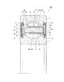
図1に示すように、この実施形態のワイヤレスセンサ付き軸受10は、内輪1、 外輪2、ボール(転動体)3と、保持器4と、八個(複数個、偶数個)の磁石5と、ヨーク6と、第一シール7と、第二シール7Aを有する。
内輪1の外周面には、軸方向中央部に内輪軌道面11が形成され、軸方向両端部にシール配置用の周溝12が形成されている。外輪2の内周面には、軸方向中央部に外輪軌道面21が形成され、軸方向両端部にシール取付溝22が形成されている。内輪軌道面11と外輪軌道面21が対向配置され、内輪軌道面11と外輪軌道面21とで形成される軌道に、ボール3が配置されている。
[First embodiment]
As shown in FIG. 1, a
On the outer peripheral surface of the
図2に示すように、保持器4は環状体からなり、ボール3を回転自在に保持するポケット41を有する。ポケット41は保持器4の周面を貫通する。ポケット41の保持器4の軸方向一端面40が開放されている。つまり、保持器4は冠型保持器である。ポケット41は保持器4の周方向に八個(複数個、偶数個)形成されている。保持器4の隣り合うポケット41間の部分(柱部)42に、軸方向に伸びる貫通穴43が形成されている。
貫通穴43の内面は、保持器4の外周側の大径面43aと、内周側の小径面43bと、保持器4の径方向に沿う一対の対向面43c,43dとからなる。貫通穴43は全ての柱部42に一つずつ形成されている。保持器4の軸方向他端面に、軸方向に凹む円環状の凹部44が形成されている。
As shown in FIG. 2, the
The inner surface of the
磁石5は、ネオジム磁石であり、全ての貫通穴43に一つずつ、保持器4の軸方向に沿ってN極とS極が並び、保持器4の周方向で各磁石のN極とS極が隣り合うように配置されている。磁石5の形状は保持器4の貫通穴43の内面に対応する形状である。磁石5は、貫通穴43の大径面43aに対応する外面51と、貫通穴43の小径面43bに対応する内面52と、貫通穴43の一対の対向面43c,43dに対応する外面53,54と、保持器4の軸方向一端面40側の軸方向一端面55と、その反対側の面である軸方向他端面56を有する。
The
磁石5の軸方向一端面55と軸方向他端面56との距離(軸方向に沿った寸法)は、保持器4の軸方向寸法より大きい。そのため、図1および図3(a)に示すように、貫通穴43に配置された磁石5は保持器4の軸方向一端面40から突出している。
図2に示すように、ヨーク6は円環状の金属板であって、保持器4の凹部44に嵌合する寸法を有する。図1に示すように、ヨーク6は凹部44に嵌合されて、貫通穴43に配置された磁石5の軸方向他端面56に接触している。ヨーク6は電磁鋼等の比透磁率の高い材料で形成されている。
The distance (the dimension along the axial direction) between the axial one
As shown in FIG. 2, the
磁石5およびヨーク6の劣化を防ぐために、磁石5およびヨーク6の表面をフッ素ゴム被膜またはパリレン(ポリパラキシレンの通称)の蒸着膜で覆うことが好ましい。保持器4は6,6−ナイロン等の非磁性材料で形成されている。保持器4を射出成形で作製する際に、磁石5とヨーク6を金型に配置して一体成形することが好ましい。射出成形された保持器4の貫通穴43に磁石5を入れて接着し、凹部44にヨーク6を嵌めて接着してもよい。
第一シール7は、図1に示すように、芯金71とゴム製のシール部72とからなる。図1および図3(b)に示すように、第一シール7の芯金71の内側面(磁石5との対向面)71aに、複数個のコイル8と一つの回路基板9が固定されている。芯金71は電磁鋼等の比透磁率の高い材料で形成されている。芯金71の内側面71aに絶縁膜が形成されている。
In order to prevent deterioration of the
As shown in FIG. 1, the
コイル8の芯金81は電磁鋼等の比透磁率の高い材料で形成されている。コイル8と磁石5の相対回転で生じる電磁誘導による発電量を向上させるために、コイル8は、薄膜コイルが積層されたものを使用してもよいし、直径が0.01mm以下の金属線が巻かれたものを使用してもよい。
第一シール7は、図1に示すように、シール部72の内周部を内輪1の周溝12に配置し、シール部72の外周部を外輪2のシール取付溝22に弾性変形状態で嵌め入れることで、内輪1と外輪2との間に設置されている。つまり、第一シール7は外輪2に固定されている。
The cored
As shown in FIG. 1, the
第二シール7Aは、 図1に示すように、芯金71Aとゴム製のシール部72とからなる通常のシールである。第二シール7Aは、シール部72の内周部を内輪1の周溝12に配置し、シール部72の外周部を外輪2のシール取付溝22に弾性変形状態で嵌め入れることで、内輪1と外輪2との間に設置されている。つまり、第二シール7Aは外輪2に固定されている。
回路基板(回路部)9は、図3(b)および図4に示すように、電源回路91と制御回路92と無線回路93とアンテナ94を有する。制御回路92上に、加速度センサ、温度センサ、回転センサ、および荷重センサの少なくともいずれかのセンサ92aが設けてある。電源回路91は、電磁誘導でコイル8に生じた電流を、整流、平滑化して、電源供給部(センサ92a、制御回路92、無線回路93)へ供給するとともに、蓄電する。そのために、電源回路91は、整流回路、平滑回路、蓄電回路、蓄電用二次電池、および定電圧出力回路を備えている。
As shown in FIG. 1, the
The circuit board (circuit unit) 9 includes a
制御回路(演算回路)92は、センサ92aで検出された情報S1を演算し、演算結果を示す信号S2と演算結果の送信周期を示す制御信号S3を、無線回路93に出力する。無線回路93は、制御回路92からの演算結果を示す信号S2を、制御信号S3に従った送信周期で無線信号に変換して、アンテナ94に出力する。アンテナ94は、演算結果(センサ92aで検出された情報)を示す無線信号を所定周期で、外部に設けた受信端末に無線送信する。
上述のように、第一シール7の芯金71の内側面71aに、複数個のコイル8と一つの回路基板9が固定されているが、さらにその上を保護カバーで覆うことが好ましい。これにより、コイル8、回路基板9、およびアンテナ94が、軸受内部に充填されたグリースや使用時に生じる摩耗粉で汚染されることが防止できる。
The control circuit (arithmetic circuit) 92 calculates the information S1 detected by the
As described above, the plurality of
この実施形態のワイヤレスセンサ付き軸受10は、外輪2をハウジングに固定し、内輪1に軸を嵌合して使用される。この状態で軸を回転させた場合、内輪1が保持器4とともに回転し、外輪2に固定された第一シール7は回転しない(つまり、第一シール7と保持器4は相対回転する)ため、第一シール7に固定されたコイル8と、保持器4に固定された磁石5との間に相対回転が生じる。
これに伴い、コイル8と磁石5との相対回転による磁束密度変化で電磁誘導が生じ、この電磁誘導でコイル8に生じた電流が、電源回路91で整流、平滑化されて、電源供給部(センサ92a、制御回路92、無線回路93)へ供給されるとともに、二次電池に蓄電される。
The bearing 10 with a wireless sensor of this embodiment is used by fixing the
Along with this, electromagnetic induction occurs due to a change in magnetic flux density due to relative rotation between the
この供給された電流により、センサ92a、制御回路92、および無線回路93が駆動し、制御回路92で、センサ92aで検出された情報S1が演算され、演算結果を示す信号S2と演算結果の送信周期を示す制御信号S3が、無線回路93に出力される。これに伴い、無線回路93で、制御回路92からの演算結果を示す信号S2が、制御信号S3に従った送信周期で無線信号に変換されて、アンテナ94に出力される。その結果、アンテナ94から、センサ92aで検出された情報を示す信号が所定周期で、外部に設けた受信端末に無線送信される。
The supplied current drives the
この実施形態のワイヤレスセンサ付き軸受10は、既存の転がり軸受の内輪1および外輪2に対する新たな加工が不要である。また、既存の転がり軸受では二つ使用されている第二シール7Aのうちの一つを、コイル8と回路基板9が固定された第一シール7に交換するとともに、既存の転がり軸受で使用されている冠型保持器を磁石5付きの保持器4に交換することで簡単に得られる。
また、この実施形態のワイヤレスセンサ付き軸受10は、コイル8と磁石5と間の電磁誘導で発電を行うため、熱発電素子であるゼーベック素子や振動発電素子であるエレクトレット素子を用いた発電を行うワイヤレスセンサ付き軸受では発電が困難であった、振動の少ない使用初期や、低速回転時であっても、必要な電力が得られてセンサ機能が発揮できる。
The bearing 10 with a wireless sensor of this embodiment does not require new processing for the
Moreover, since the bearing 10 with a wireless sensor of this embodiment produces electric power by the electromagnetic induction between the
また、第一シール7にコイル8と回路基板9を固定するとともに、保持器4の柱部42に貫通穴43を設けて、この貫通穴43に配置した磁石5を第一シール7側に突出させているため、既存の転がり軸受と比較した軸受内部空間の低下量は少ない。
また、磁石5の大部分が保持器4に埋め込まれた構造となっているため、コイル8に対して垂直磁場変化の強い磁石を使用することが可能となる。その結果、磁石の埋め込み量が少ない構造のものと比較して発電効率が高くなる。
また、この実施形態のワイヤレスセンサ付き軸受10は、回路基板9が、演算結果を示す信号をアンテナ94が所定周期で、外部に設けた受信端末に無線送信するように構成されている。これにより、演算時および無線送信時以外には無線回路93およびアンテナ94が作動しないため、常時作動するように構成されているものと比較して、消費電力が低減できる。
In addition, the
In addition, since most of the
Further, the bearing 10 with a wireless sensor of this embodiment is configured such that the circuit board 9 wirelessly transmits a signal indicating a calculation result to a receiving terminal provided outside at a predetermined cycle. Thereby, since the
なお、この実施形態のワイヤレスセンサ付き軸受10では、アンテナ94が回路基板9の部品実装面に形成されているが、回路基板9の部品実装面とは反対面にアンテナを形成し、芯金71とシール部72に穴を設けて、アンテナを第一シール7から軸受外部に突出させてもよい。
また、この実施形態のワイヤレスセンサ付き軸受10では、一つの回路基板9に、電源回路91と制御回路92と無線回路93とアンテナ94が形成され、その回路基板9が芯金71に固定されているが、電源回路91と制御回路92と無線回路93とアンテナ94が別々の基板に形成されていてもよい。さらに、電源回路91と制御回路92と無線回路93とアンテナ94は、芯金71の内側面71aに形成された絶縁膜上に直接形成されていてもよい。
In the wireless sensor-equipped
Moreover, in the
また、この実施形態のワイヤレスセンサ付き軸受10では、センサが制御回路92上に(つまり、第一シール7の芯金71に)形成されているため、既存の転がり軸受を構成する内輪1および外輪2に対する新たな加工が不要であり、外部に突起物が存在しない。
しかし、第一シール7が固定されている外輪2の軸方向端面、外周面、および内周面の少なくともいずれかの面に、センサを固定していもよい。第一シール7が内輪に固定されている場合は、内輪の軸方向端面、外周面、および内周面の少なくともいずれかの面にセンサを固定していもよい。また、上記いずれかの面に、センサを固定するための凹部を設けてもよい。
Moreover, in the
However, the sensor may be fixed to at least one of the axial end surface, outer peripheral surface, and inner peripheral surface of the
また、この実施形態のワイヤレスセンサ付き軸受10では、磁石5として、ネオジム磁石を使用しているが、サマリウムコバルト磁石等の他の磁石を使用してもよい。
また、この実施形態のワイヤレスセンサ付き軸受10では、磁石5が保持器4の軸方向一端面40から突出しているが、磁石5の軸方向一端面55が保持器4の軸方向一端面40と同じかこれより内側になっていてもよい。さらに、磁石5の軸方向一端面55を保持器4の軸方向一端面40より内側とし、保持器4を合成樹脂の射出成形で作製する際に、軸方向一端面55が合成樹脂で薄く覆われるように磁石5を一体成形してもよい。
つまり、複数個の磁石5は、環状体である保持器4の周方向で各磁石のN極とS極が隣り合うように固定され、コイル8と磁石5と間で電磁誘導が生じる状態となっていればよい。なお、合成樹脂で磁石5の軸方向一端面55が覆われている場合は、磁石5は合成樹脂製被覆部を介してコイル8と対向する。
Moreover, in the
Moreover, in the
That is, the plurality of
[第二実施形態]
図5に示すように、第二実施形態のワイヤレスセンサ付き軸受10Aは、内輪1、 外輪2、ボール(転動体)3と、保持器4Aと、磁石5Aと、ヨーク6と、第一シール7と、第二シール7Aを有する。このワイヤレスセンサ付き軸受10Aは、保持器4Aおよび磁石5Aの形状を除いて、第一実施形態のワイヤレスセンサ付き軸受10と同じである。
保持器4Aの隣り合うポケット間の部分(柱部)42に、軸方向一端面40から軸方向に凹む凹部45が形成されている。凹部45は、全ての柱部42に一つずつ形成されている。つまり、保持器4Aは、第一実施形態の保持器4の貫通穴43の代わりに凹部45を有する。これ以外の点において、保持器4Aは第一実施形態の保持器4と同じである。
[Second Embodiment]
As shown in FIG. 5, the bearing 10A with a wireless sensor of the second embodiment includes an
A
磁石5Aは、全ての凹部45に一つずつ、保持器4Aの周方向でN極とS極が隣り合うように配置されている。磁石5Aは、保持器4Aの凹部45内に配置される基部57と、保持器4Aの軸方向一端面40から突出する突出部58とを有する。基部57は突出部58より薄く、両部分の境界に段部を有する。
基部57の形状は保持器4Aの凹部45の内面に対応する形状である。つまり、基部57は、凹部45の大径面45aに対応する外面、凹部45の小径面45bに対応する内面等を有する。突出部58は、保持器4の軸方向一端面40側の軸方向一端面55を有する。基部57は、軸方向一端面55の反対側の面である軸方向他端面56を有する。
磁石5Aの基部57を保持器4Aの凹部45に入れ、凹部44にヨーク6を嵌めることで、凹部45の底板46を介して基部57とヨーク6が引き合う。そのため、この実施形態のワイヤレスセンサ付き軸受10Aでは、接着剤を用いずに、磁石5Aおよびヨーク6を保持器4Aに固定することができる。
One
The shape of the
The
[第三実施形態]
図6に示すように、第三実施形態のワイヤレスセンサ付き軸受10Bは、内輪1、 外輪2、ボール(転動体)3と、保持器4Bと、磁石5Bと、ヨーク6と、第一シール7と、第二シール7Aを有する。このワイヤレスセンサ付き軸受10Bは、保持器4Bおよび磁石5Bの形状と、ヨーク6の固定位置を除いて、第一実施形態のワイヤレスセンサ付き軸受10と同じである。
磁石5Bは、保持器4Bの軸方向で厚さの異なる基部591と突出部592からなる。磁石5Bの基部591は突出部592より厚く、両部分の境界に段部を有する。
[Third embodiment]
As shown in FIG. 6, the bearing 10B with the wireless sensor of the third embodiment includes an
The
このワイヤレスセンサ付き軸受10Bでは、保持器4Bを射出成形で作製する際に、磁石5Bとヨーク6を金型に配置して一体成形を行っている。これにより、磁石5Bが、保持器4Bの隣り合うポケット間の部分(柱部)42に一つずつ、保持器4Bの周方向でN極とS極が隣り合うように配置されている。
磁石5Bの突出部592は、段部側の部分を除いて、保持器4Bの軸方向一端面40から突出している。磁石5Bの基部591は全て保持器4B内に配置されている。磁石5Bの軸方向他端面56にヨーク6が接触している。ヨーク6の外側に保持器4Bの底部47が存在する。
In the wireless sensor-equipped
The protruding
1 内輪
11 内輪軌道面
12 シール配置用の周溝
2 外輪
21 外輪軌道面
22 シール取付溝
3 ボール(転動体)
4 保持器
4A 保持器
4B 保持器
41 ポケット
40 保持器の軸方向一端面
42 柱部(ポケット間の部分)
43 貫通穴
44 保持器の凹部
5 磁石
5A 磁石
5B 磁石
6 ヨーク
7 第一シール
71 第一シールの芯金
71a 第一シールの芯金の内側面(磁石との対向面)
72 シール部
7A 第二シール
71A 第二シールの芯金
8 コイル
9 回路基板(回路部)
91 電源回路
92 制御回路(演算回路、電源供給部)
93 無線回路(電源供給部)
94 アンテナ
92a センサ(電源供給部)
10 ワイヤレスセンサ付き軸受
DESCRIPTION OF
4
43 Through
72
91
93 Radio circuit (power supply unit)
94
10 Bearing with wireless sensor
Claims (2)
前記内輪軌道面と対向配置される外輪軌道面を内周面に有する外輪と、
前記内輪軌道面と前記外輪軌道面とで形成される軌道に配置された転動体と、
環状体からなる保持器であって、前記転動体を回転自在に保持するポケットを有し、前記ポケットは前記環状体の周面を貫通し、前記ポケットは前記環状体の周方向に複数個形成された保持器と、
複数の磁石であって、前記保持器の前記ポケット同士の間に一つずつ、前記環状体の周方向で各磁石のN極とS極が隣り合うように固定された磁石と、
前記内輪と前記外輪との間を軸方向一端部で密封する第一シールであって、前記保持器に対して相対回転する第一シールと、
前記第一シールの前記磁石との対向面に固定されたコイルと、
前記内輪と前記外輪との間を軸方向他端部で密封する第二シールと、
前記内輪、前記外輪、および前記第一シールのいずれかに設置されたセンサと、
前記第一シールに形成された回路部であって、前記磁石と前記コイルとの相対回転による電磁誘導で前記コイルに生じた電流を電源供給部へ供給する電源回路と、前記センサで検出された検出情報から検出値を演算する演算回路と、演算結果を示す無線信号を作成する無線回路と、を有する回路部と、
前記無線信号を送信するアンテナであって、前記第一シールに固定されたアンテナと、を有するワイヤレスセンサ付き軸受。 An inner ring having an inner ring raceway surface on the outer peripheral surface;
An outer ring having, on the inner peripheral surface, an outer ring raceway surface disposed opposite to the inner ring raceway surface;
A rolling element disposed on a track formed by the inner ring raceway surface and the outer ring raceway surface;
A cage made of an annular body, having a pocket for rotatably holding the rolling element, wherein the pocket penetrates the circumferential surface of the annular body, and a plurality of pockets are formed in the circumferential direction of the annular body A retained cage;
A plurality of magnets, one between the pockets of the cage, and fixed so that the N pole and S pole of each magnet are adjacent to each other in the circumferential direction of the annular body;
A first seal that seals between the inner ring and the outer ring at one axial end, and a first seal that rotates relative to the cage;
A coil fixed to a surface of the first seal facing the magnet;
A second seal that seals between the inner ring and the outer ring at the other axial end;
A sensor installed on any of the inner ring, the outer ring, and the first seal;
A circuit unit formed on the first seal, the power source circuit supplying current generated in the coil to the power supply unit by electromagnetic induction caused by relative rotation between the magnet and the coil, and detected by the sensor A circuit unit having an arithmetic circuit for calculating a detection value from detection information, and a radio circuit for creating a radio signal indicating a calculation result;
A wireless sensor-equipped bearing having an antenna for transmitting the radio signal, the antenna being fixed to the first seal.
Priority Applications (4)
| Application Number | Priority Date | Filing Date | Title |
|---|---|---|---|
| JP2016074109A JP6264393B2 (en) | 2016-04-01 | 2016-04-01 | Bearing with wireless sensor |
| PCT/JP2017/013777 WO2017171067A1 (en) | 2016-04-01 | 2017-03-31 | Bearing with wireless sensor |
| US16/073,896 US10408269B2 (en) | 2016-04-01 | 2017-03-31 | Wireless sensor-equipped bearing |
| EP17775598.0A EP3421830B1 (en) | 2016-04-01 | 2017-03-31 | Bearing with wireless sensor |
Applications Claiming Priority (1)
| Application Number | Priority Date | Filing Date | Title |
|---|---|---|---|
| JP2016074109A JP6264393B2 (en) | 2016-04-01 | 2016-04-01 | Bearing with wireless sensor |
Publications (3)
| Publication Number | Publication Date |
|---|---|
| JP2017187061A true JP2017187061A (en) | 2017-10-12 |
| JP2017187061A5 JP2017187061A5 (en) | 2017-11-24 |
| JP6264393B2 JP6264393B2 (en) | 2018-01-24 |
Family
ID=60046284
Family Applications (1)
| Application Number | Title | Priority Date | Filing Date |
|---|---|---|---|
| JP2016074109A Active JP6264393B2 (en) | 2016-04-01 | 2016-04-01 | Bearing with wireless sensor |
Country Status (1)
| Country | Link |
|---|---|
| JP (1) | JP6264393B2 (en) |
Cited By (2)
| Publication number | Priority date | Publication date | Assignee | Title |
|---|---|---|---|---|
| US11293494B2 (en) | 2018-02-23 | 2022-04-05 | Ntn Corporation | Bearing |
| CN115901253A (en) * | 2022-10-09 | 2023-04-04 | 南通理工学院 | Wireless sensor with power-off protection and reminding functions |
Citations (6)
| Publication number | Priority date | Publication date | Assignee | Title |
|---|---|---|---|---|
| JPH0380120U (en) * | 1989-12-05 | 1991-08-16 | ||
| JP2003097582A (en) * | 2001-09-27 | 2003-04-03 | Nsk Ltd | Bearing device with sensor |
| JP2004353735A (en) * | 2003-05-28 | 2004-12-16 | Nsk Ltd | Rotating device with sensor and its forming method |
| JP2005180985A (en) * | 2003-12-17 | 2005-07-07 | Nsk Ltd | Load measuring device for rolling bearing unit |
| JP2013007672A (en) * | 2011-06-24 | 2013-01-10 | Nsk Ltd | Rolling bearing with sensor |
| JP2015059620A (en) * | 2013-09-19 | 2015-03-30 | 日本精工株式会社 | Rolling bearing |
-
2016
- 2016-04-01 JP JP2016074109A patent/JP6264393B2/en active Active
Patent Citations (6)
| Publication number | Priority date | Publication date | Assignee | Title |
|---|---|---|---|---|
| JPH0380120U (en) * | 1989-12-05 | 1991-08-16 | ||
| JP2003097582A (en) * | 2001-09-27 | 2003-04-03 | Nsk Ltd | Bearing device with sensor |
| JP2004353735A (en) * | 2003-05-28 | 2004-12-16 | Nsk Ltd | Rotating device with sensor and its forming method |
| JP2005180985A (en) * | 2003-12-17 | 2005-07-07 | Nsk Ltd | Load measuring device for rolling bearing unit |
| JP2013007672A (en) * | 2011-06-24 | 2013-01-10 | Nsk Ltd | Rolling bearing with sensor |
| JP2015059620A (en) * | 2013-09-19 | 2015-03-30 | 日本精工株式会社 | Rolling bearing |
Cited By (3)
| Publication number | Priority date | Publication date | Assignee | Title |
|---|---|---|---|---|
| US11293494B2 (en) | 2018-02-23 | 2022-04-05 | Ntn Corporation | Bearing |
| CN115901253A (en) * | 2022-10-09 | 2023-04-04 | 南通理工学院 | Wireless sensor with power-off protection and reminding functions |
| CN115901253B (en) * | 2022-10-09 | 2024-03-05 | 南通理工学院 | Wireless sensor with power-off protection and reminding functions |
Also Published As
| Publication number | Publication date |
|---|---|
| JP6264393B2 (en) | 2018-01-24 |
Similar Documents
| Publication | Publication Date | Title |
|---|---|---|
| WO2017171067A1 (en) | Bearing with wireless sensor | |
| JP6743361B2 (en) | Bearing with wireless sensor | |
| US20100172605A1 (en) | Rolling bearing device comprising an integrated sensor system | |
| JP6264393B2 (en) | Bearing with wireless sensor | |
| JP2021127831A (en) | Bearing device, spacer, and manufacturing method | |
| JP6891445B2 (en) | Bearing with wireless sensor | |
| JP5684529B2 (en) | motor | |
| CN109889005A (en) | The motor of outer-rotor type | |
| JP6743677B2 (en) | Bearing with wireless sensor and bearing feeding system | |
| CN111727328B (en) | Bearing assembly | |
| JP6264404B2 (en) | Bearing with wireless sensor | |
| JP6264394B2 (en) | Bearing with wireless sensor | |
| US20220154774A1 (en) | Rolling bearing and sensor-equipped rolling bearing | |
| JP2019007580A (en) | Bearing with wireless sensor | |
| JP2017187061A5 (en) | ||
| JP2013061030A (en) | Bearing with rotation sensor | |
| JP2007333142A (en) | Rolling bearing | |
| WO2023182091A1 (en) | Bearing device | |
| JP7450657B2 (en) | bearing device | |
| JP2009020048A (en) | Contact sensor | |
| JP4829824B2 (en) | Rolling bearing with rotation sensor | |
| JP2023147975A (en) | bearing device | |
| CN113574286A (en) | Rolling bearing and rolling bearing equipped with sensor | |
| WO2023189277A1 (en) | Bearing device | |
| WO2023189278A1 (en) | Bearing device |
Legal Events
| Date | Code | Title | Description |
|---|---|---|---|
| A521 | Request for written amendment filed |
Free format text: JAPANESE INTERMEDIATE CODE: A523 Effective date: 20170922 |
|
| A621 | Written request for application examination |
Free format text: JAPANESE INTERMEDIATE CODE: A621 Effective date: 20170922 |
|
| A871 | Explanation of circumstances concerning accelerated examination |
Free format text: JAPANESE INTERMEDIATE CODE: A871 Effective date: 20170922 |
|
| A975 | Report on accelerated examination |
Free format text: JAPANESE INTERMEDIATE CODE: A971005 Effective date: 20171005 |
|
| TRDD | Decision of grant or rejection written | ||
| A01 | Written decision to grant a patent or to grant a registration (utility model) |
Free format text: JAPANESE INTERMEDIATE CODE: A01 Effective date: 20171121 |
|
| A61 | First payment of annual fees (during grant procedure) |
Free format text: JAPANESE INTERMEDIATE CODE: A61 Effective date: 20171204 |
|
| R150 | Certificate of patent or registration of utility model |
Ref document number: 6264393 Country of ref document: JP Free format text: JAPANESE INTERMEDIATE CODE: R150 |