JP2017185931A - Setting structure of cooling system in construction machine - Google Patents
Setting structure of cooling system in construction machine Download PDFInfo
- Publication number
- JP2017185931A JP2017185931A JP2016076995A JP2016076995A JP2017185931A JP 2017185931 A JP2017185931 A JP 2017185931A JP 2016076995 A JP2016076995 A JP 2016076995A JP 2016076995 A JP2016076995 A JP 2016076995A JP 2017185931 A JP2017185931 A JP 2017185931A
- Authority
- JP
- Japan
- Prior art keywords
- heat exchanger
- radiator
- cooling
- intercooler
- reservoir tank
- Prior art date
- Legal status (The legal status is an assumption and is not a legal conclusion. Google has not performed a legal analysis and makes no representation as to the accuracy of the status listed.)
- Granted
Links
- 238000001816 cooling Methods 0.000 title claims abstract description 90
- 238000010276 construction Methods 0.000 title claims abstract description 21
- 239000000498 cooling water Substances 0.000 claims abstract description 26
- 238000000638 solvent extraction Methods 0.000 claims description 4
- 238000004904 shortening Methods 0.000 abstract 1
- 239000003921 oil Substances 0.000 description 34
- XLYOFNOQVPJJNP-UHFFFAOYSA-N water Substances O XLYOFNOQVPJJNP-UHFFFAOYSA-N 0.000 description 9
- 239000002826 coolant Substances 0.000 description 6
- 239000012530 fluid Substances 0.000 description 4
- 239000010720 hydraulic oil Substances 0.000 description 3
- 238000004140 cleaning Methods 0.000 description 2
- 230000000694 effects Effects 0.000 description 2
- 239000007791 liquid phase Substances 0.000 description 2
- 238000012423 maintenance Methods 0.000 description 2
- 239000012071 phase Substances 0.000 description 2
- 230000005855 radiation Effects 0.000 description 2
- 239000012809 cooling fluid Substances 0.000 description 1
- 238000010586 diagram Methods 0.000 description 1
- 238000002347 injection Methods 0.000 description 1
- 239000007924 injection Substances 0.000 description 1
- 230000002093 peripheral effect Effects 0.000 description 1
- 238000000926 separation method Methods 0.000 description 1
- 238000011144 upstream manufacturing Methods 0.000 description 1
Images


Classifications
-
- F—MECHANICAL ENGINEERING; LIGHTING; HEATING; WEAPONS; BLASTING
- F01—MACHINES OR ENGINES IN GENERAL; ENGINE PLANTS IN GENERAL; STEAM ENGINES
- F01P—COOLING OF MACHINES OR ENGINES IN GENERAL; COOLING OF INTERNAL-COMBUSTION ENGINES
- F01P3/00—Liquid cooling
- F01P3/18—Arrangements or mounting of liquid-to-air heat-exchangers
-
- B—PERFORMING OPERATIONS; TRANSPORTING
- B60—VEHICLES IN GENERAL
- B60K—ARRANGEMENT OR MOUNTING OF PROPULSION UNITS OR OF TRANSMISSIONS IN VEHICLES; ARRANGEMENT OR MOUNTING OF PLURAL DIVERSE PRIME-MOVERS IN VEHICLES; AUXILIARY DRIVES FOR VEHICLES; INSTRUMENTATION OR DASHBOARDS FOR VEHICLES; ARRANGEMENTS IN CONNECTION WITH COOLING, AIR INTAKE, GAS EXHAUST OR FUEL SUPPLY OF PROPULSION UNITS IN VEHICLES
- B60K11/00—Arrangement in connection with cooling of propulsion units
- B60K11/02—Arrangement in connection with cooling of propulsion units with liquid cooling
- B60K11/04—Arrangement or mounting of radiators, radiator shutters, or radiator blinds
-
- B—PERFORMING OPERATIONS; TRANSPORTING
- B60—VEHICLES IN GENERAL
- B60K—ARRANGEMENT OR MOUNTING OF PROPULSION UNITS OR OF TRANSMISSIONS IN VEHICLES; ARRANGEMENT OR MOUNTING OF PLURAL DIVERSE PRIME-MOVERS IN VEHICLES; AUXILIARY DRIVES FOR VEHICLES; INSTRUMENTATION OR DASHBOARDS FOR VEHICLES; ARRANGEMENTS IN CONNECTION WITH COOLING, AIR INTAKE, GAS EXHAUST OR FUEL SUPPLY OF PROPULSION UNITS IN VEHICLES
- B60K11/00—Arrangement in connection with cooling of propulsion units
- B60K11/06—Arrangement in connection with cooling of propulsion units with air cooling
-
- E—FIXED CONSTRUCTIONS
- E02—HYDRAULIC ENGINEERING; FOUNDATIONS; SOIL SHIFTING
- E02F—DREDGING; SOIL-SHIFTING
- E02F9/00—Component parts of dredgers or soil-shifting machines, not restricted to one of the kinds covered by groups E02F3/00 - E02F7/00
- E02F9/08—Superstructures; Supports for superstructures
- E02F9/0858—Arrangement of component parts installed on superstructures not otherwise provided for, e.g. electric components, fenders, air-conditioning units
- E02F9/0866—Engine compartment, e.g. heat exchangers, exhaust filters, cooling devices, silencers, mufflers, position of hydraulic pumps in the engine compartment
-
- F—MECHANICAL ENGINEERING; LIGHTING; HEATING; WEAPONS; BLASTING
- F01—MACHINES OR ENGINES IN GENERAL; ENGINE PLANTS IN GENERAL; STEAM ENGINES
- F01P—COOLING OF MACHINES OR ENGINES IN GENERAL; COOLING OF INTERNAL-COMBUSTION ENGINES
- F01P11/00—Component parts, details, or accessories not provided for in, or of interest apart from, groups F01P1/00 - F01P9/00
- F01P11/02—Liquid-coolant filling, overflow, venting, or draining devices
- F01P11/029—Expansion reservoirs
-
- F—MECHANICAL ENGINEERING; LIGHTING; HEATING; WEAPONS; BLASTING
- F01—MACHINES OR ENGINES IN GENERAL; ENGINE PLANTS IN GENERAL; STEAM ENGINES
- F01P—COOLING OF MACHINES OR ENGINES IN GENERAL; COOLING OF INTERNAL-COMBUSTION ENGINES
- F01P3/00—Liquid cooling
- F01P3/20—Cooling circuits not specific to a single part of engine or machine
-
- F—MECHANICAL ENGINEERING; LIGHTING; HEATING; WEAPONS; BLASTING
- F01—MACHINES OR ENGINES IN GENERAL; ENGINE PLANTS IN GENERAL; STEAM ENGINES
- F01P—COOLING OF MACHINES OR ENGINES IN GENERAL; COOLING OF INTERNAL-COMBUSTION ENGINES
- F01P5/00—Pumping cooling-air or liquid coolants
- F01P5/02—Pumping cooling-air; Arrangements of cooling-air pumps, e.g. fans or blowers
- F01P5/06—Guiding or ducting air to, or from, ducted fans
-
- F—MECHANICAL ENGINEERING; LIGHTING; HEATING; WEAPONS; BLASTING
- F28—HEAT EXCHANGE IN GENERAL
- F28D—HEAT-EXCHANGE APPARATUS, NOT PROVIDED FOR IN ANOTHER SUBCLASS, IN WHICH THE HEAT-EXCHANGE MEDIA DO NOT COME INTO DIRECT CONTACT
- F28D1/00—Heat-exchange apparatus having stationary conduit assemblies for one heat-exchange medium only, the media being in contact with different sides of the conduit wall, in which the other heat-exchange medium is a large body of fluid, e.g. domestic or motor car radiators
- F28D1/02—Heat-exchange apparatus having stationary conduit assemblies for one heat-exchange medium only, the media being in contact with different sides of the conduit wall, in which the other heat-exchange medium is a large body of fluid, e.g. domestic or motor car radiators with heat-exchange conduits immersed in the body of fluid
- F28D1/04—Heat-exchange apparatus having stationary conduit assemblies for one heat-exchange medium only, the media being in contact with different sides of the conduit wall, in which the other heat-exchange medium is a large body of fluid, e.g. domestic or motor car radiators with heat-exchange conduits immersed in the body of fluid with tubular conduits
- F28D1/0408—Multi-circuit heat exchangers, e.g. integrating different heat exchange sections in the same unit or heat exchangers for more than two fluids
- F28D1/0426—Multi-circuit heat exchangers, e.g. integrating different heat exchange sections in the same unit or heat exchangers for more than two fluids with units having particular arrangement relative to the large body of fluid, e.g. with interleaved units or with adjacent heat exchange units in common air flow or with units extending at an angle to each other or with units arranged around a central element
- F28D1/0443—Combination of units extending one beside or one above the other
-
- B—PERFORMING OPERATIONS; TRANSPORTING
- B60—VEHICLES IN GENERAL
- B60Y—INDEXING SCHEME RELATING TO ASPECTS CROSS-CUTTING VEHICLE TECHNOLOGY
- B60Y2200/00—Type of vehicle
- B60Y2200/40—Special vehicles
- B60Y2200/41—Construction vehicles, e.g. graders, excavators
- B60Y2200/412—Excavators
-
- F—MECHANICAL ENGINEERING; LIGHTING; HEATING; WEAPONS; BLASTING
- F01—MACHINES OR ENGINES IN GENERAL; ENGINE PLANTS IN GENERAL; STEAM ENGINES
- F01P—COOLING OF MACHINES OR ENGINES IN GENERAL; COOLING OF INTERNAL-COMBUSTION ENGINES
- F01P3/00—Liquid cooling
- F01P3/18—Arrangements or mounting of liquid-to-air heat-exchangers
- F01P2003/182—Arrangements or mounting of liquid-to-air heat-exchangers with multiple heat-exchangers
-
- F—MECHANICAL ENGINEERING; LIGHTING; HEATING; WEAPONS; BLASTING
- F01—MACHINES OR ENGINES IN GENERAL; ENGINE PLANTS IN GENERAL; STEAM ENGINES
- F01P—COOLING OF MACHINES OR ENGINES IN GENERAL; COOLING OF INTERNAL-COMBUSTION ENGINES
- F01P2060/00—Cooling circuits using auxiliaries
- F01P2060/02—Intercooler
-
- F—MECHANICAL ENGINEERING; LIGHTING; HEATING; WEAPONS; BLASTING
- F01—MACHINES OR ENGINES IN GENERAL; ENGINE PLANTS IN GENERAL; STEAM ENGINES
- F01P—COOLING OF MACHINES OR ENGINES IN GENERAL; COOLING OF INTERNAL-COMBUSTION ENGINES
- F01P2060/00—Cooling circuits using auxiliaries
- F01P2060/04—Lubricant cooler
Landscapes
- Engineering & Computer Science (AREA)
- Mechanical Engineering (AREA)
- Combustion & Propulsion (AREA)
- Chemical & Material Sciences (AREA)
- General Engineering & Computer Science (AREA)
- Transportation (AREA)
- Mining & Mineral Resources (AREA)
- Civil Engineering (AREA)
- Structural Engineering (AREA)
- Thermal Sciences (AREA)
- Physics & Mathematics (AREA)
- Component Parts Of Construction Machinery (AREA)
- Cooling, Air Intake And Gas Exhaust, And Fuel Tank Arrangements In Propulsion Units (AREA)
Abstract
Description
本発明は、油圧ショベル等の建設機械において、ラジエータ等の複数の熱交換器、冷却ファン、リザーバータンク等を備えた冷却システムの配設構造の技術分野に関するものである。 The present invention relates to a technical field of an arrangement structure of a cooling system including a plurality of heat exchangers such as a radiator, a cooling fan, a reservoir tank, and the like in a construction machine such as a hydraulic excavator.
一般に、油圧ショベル等の建設機械には、エンジン冷却水を冷却するためのラジエータや、作動油を冷却するためのオイルクーラー、過給機で生じる圧縮空気を冷却するためのインタークーラー等の各種熱交換器が搭載されるとともに、これら熱交換器に冷却風を供給する冷却ファンや、エンジン冷却水の熱膨張による体積変化に対応するべくエンジン冷却水を貯留するリザーバータンク等を備えた冷却システムが設けられている。
前記リザーバータンクとしては、従前から、圧力調整機能を有するラジエータキャップを介してラジエータに接続された大気開放型のリザーバータンクが汎用的に用いられている。これに対し、ラジエータとエンジンとの間の冷却水循環系にラジエータと並列状に接続される加圧密閉式のリザーバータンクも知られている(例えば、特許文献1参照)。このような加圧密閉式リザーバータンクを用いた場合は、エンジン冷却水の一部がリザーバータンクを経由して循環するとともに、該リザーバータンク内の気相部により冷却水の熱膨張による体積変化を吸収することになるため、冷却水循環系内においてエア抜きがなされることになり、前記大気開放型のリザーバータンクと比して気泡分離性能に優れるという利点がある。
一方、油圧ショベル等の建設機械には、前述したようにラジエータ、オイルクーラー、インタークーラー等の複数の熱交換器が設けられるが、この場合に、これらラジエータを含む複数の熱交換器を、冷却ファンの冷却風の流れに対して左右に並列する状態で配して略正方形状をした冷却装置としてユニット化し、該ユニット化した冷却装置を運転室の後方の冷却装置収納部に収納したものが知られている(例えば、特許文献2参照)。このように複数の熱交換器を左右に並列状に配設することにより、何れの熱交換器も良好な冷却効率を確保できるとともに、各熱交換器の清掃等のメンテナンスを容易に行うことができる。
In general, for construction machines such as hydraulic excavators, various heat exchanges such as a radiator for cooling engine coolant, an oil cooler for cooling hydraulic oil, and an intercooler for cooling compressed air generated in a supercharger And a cooling system that includes a cooling fan that supplies cooling air to these heat exchangers and a reservoir tank that stores engine cooling water in order to cope with volume changes due to thermal expansion of engine cooling water. It has been.
As the reservoir tank, an open-air reservoir tank connected to the radiator via a radiator cap having a pressure adjusting function has been used for a general purpose. On the other hand, there is also known a pressurized and sealed reservoir tank connected in parallel with the radiator to the cooling water circulation system between the radiator and the engine (for example, see Patent Document 1). When such a pressurized sealed reservoir tank is used, a part of the engine cooling water circulates through the reservoir tank, and the volume change due to the thermal expansion of the cooling water is absorbed by the gas phase portion in the reservoir tank. Therefore, air is vented in the cooling water circulation system, and there is an advantage that the air bubble separation performance is excellent as compared with the air-released reservoir tank.
On the other hand, a construction machine such as a hydraulic excavator is provided with a plurality of heat exchangers such as a radiator, an oil cooler, and an intercooler as described above. In this case, a plurality of heat exchangers including these radiators are connected to a cooling fan. It is known that it is unitized as a cooling device having a substantially square shape, arranged in parallel with the flow of cooling air in the left and right, and the unitized cooling device is stored in the cooling device storage part at the rear of the cab. (For example, refer to Patent Document 2). By arranging a plurality of heat exchangers in parallel on the left and right in this way, any heat exchanger can ensure good cooling efficiency and can easily perform maintenance such as cleaning of each heat exchanger. it can.
ところで、前述した加圧密閉式のリザーバータンクは、エンジン冷却水の循環系内において冷却水中のエア抜きを行うため、エンジンおよびラジエータを含む冷却水循環路の最高部よりも高い位置に設ける必要がある。このため、前記特許文献2のようにラジエータを含む複数の熱交換器を左右に並列状に配してユニット化した冷却装置が設けられているものにおいて加圧密閉式のリザーバータンクを採用しようとした場合には、ラジエータの上端位置よりも高位にするためにリザーバータンクを冷却装置から上方に突出する状態で配設しなければならず、その分冷却装置収納部の天井高さを高くする必要が生じて、運転室からの後方視界が妨げられるという問題があり、ここに本発明の解決すべき課題がある。
By the way, the above-described pressurized and sealed reservoir tank needs to be provided at a position higher than the highest part of the cooling water circulation path including the engine and the radiator in order to vent the cooling water in the circulation system of the engine cooling water. For this reason, as in the above-mentioned
本発明は、上記の如き実情に鑑みこれらの課題を解決することを目的として創作されたものであって、請求項1の発明は、ラジエータを含む複数の熱交換器と、これら熱交換器に冷却風を供給する冷却ファンと、前記ラジエータとエンジンとの間の冷却水循環系にラジエータと並列状に接続される加圧密閉式リザーバータンクとを備えた建設機械の冷却システムにおいて、前記複数の熱交換器を、ラジエータ以外の少なくとも一つの熱交換器を上段熱交換器とし、該上段熱交換器以外のラジエータを含む熱交換器を下段熱交換器として上段熱交換器の下方に配設するとともに、該配設された状態での上段熱交換器全体の横幅を下段熱交換器全体の横幅よりも短くして上段熱交換器の横方にタンク用スペースを形成し、該タンク用スペースに前記リザーバータンクを配設したことを特徴とする建設機械における冷却システムの配設構造である。
請求項2の発明は、請求項1において、上段熱交換器と下段熱交換器とは冷却風の流れに対して上下に並列する状態で配されるとともに、上段熱交換器同士、下段熱交換器同士は冷却風の流れに対して上下または左右に並列する状態で配されることを特徴とする建設機械における冷却システムの配設構造である。
請求項3の発明は、請求項1または2において、下段熱交換器はラジエータとオイルクーラーであり、上段熱交換器はインタークーラーであることを特徴とする建設機械における冷却システムの配設構造である。
請求項4の発明は、請求項1乃至3の何れか一項において、上段熱交換器および下段熱交換器を四角枠状のフレーム部材に組込み、該フレーム部材に冷却ファンを囲うファンシュラウドを連結するとともに、フレーム部材およびファンシュラウドの上側隅部に、タンク用スペースを区画する段差状凹部を形成したことを特徴とする建設機械における冷却システムの配設構造である。
The present invention has been created in view of the above-described circumstances to solve these problems. The invention of claim 1 includes a plurality of heat exchangers including a radiator, and these heat exchangers. In the cooling system for a construction machine, comprising: a cooling fan that supplies cooling air; and a pressurized sealed reservoir tank that is connected in parallel with the radiator in a cooling water circulation system between the radiator and the engine. A heat exchanger including at least one heat exchanger other than a radiator as an upper heat exchanger, a heat exchanger including a radiator other than the upper heat exchanger as a lower heat exchanger, and disposed below the upper heat exchanger, The horizontal width of the entire upper heat exchanger in the arranged state is made shorter than the horizontal width of the entire lower heat exchanger to form a tank space on the side of the upper heat exchanger. A mounting structure of a cooling system in a construction machine, characterized in that arranged the reservoir tank.
According to a second aspect of the present invention, in the first aspect, the upper stage heat exchanger and the lower stage heat exchanger are arranged in parallel with each other with respect to the flow of the cooling air. The containers are arranged in a state of being parallel to the flow of cooling air in the vertical or horizontal direction, and the cooling system is arranged in a construction machine.
A third aspect of the present invention is the cooling system arrangement structure in the construction machine according to the first or second aspect, wherein the lower heat exchanger is a radiator and an oil cooler, and the upper heat exchanger is an intercooler. .
According to a fourth aspect of the present invention, in any one of the first to third aspects, the upper stage heat exchanger and the lower stage heat exchanger are incorporated in a square frame-shaped frame member, and a fan shroud surrounding the cooling fan is connected to the frame member. In addition, a cooling system arrangement structure in a construction machine is characterized in that a stepped recess for partitioning a tank space is formed in the upper corner of the frame member and the fan shroud.
請求項1の発明とすることにより、加圧密閉式のリザーバータンクを、ラジエータの上端位置よりも高位で、且つ、熱交換器全体から上方に突出しない状態で配設できることになって、熱交換器が収納される収納室の天井高さを抑えることができる。
請求項2の発明とすることにより、ラジエータを含む複数の熱交換器を、冷却風の流れに対して互いに重ならない状態で配することができ、良好な冷却効率を確保できるとともに、清掃等のメンテナンス性に優れる。
請求項3の発明とすることにより、ラジエータとオイルクーラーとインタークーラーとが設けられている建設機械に本発明を適用できるとともに、インタークーラーを上段熱交換器とすることによって、インタークーラーとエンジンの吸気側とを接続する配管を短くすることができる。
請求項4の発明とすることにより、フレーム部材およびファンシュラウドに形成された段差状凹部によってリザーバータンクを冷却風から遮蔽できるとともに、段差状凹部が形成されるフレーム部材およびファンシュラウドの上側隅部は冷却ファンのファン回転軌跡から遠い位置であるため、冷却効率への影響を可及的に少なくすることができる。
According to the first aspect of the present invention, the pressurized and sealed reservoir tank can be disposed in a state higher than the upper end position of the radiator and not projecting upward from the entire heat exchanger. The height of the ceiling of the storage room in which is stored can be suppressed.
By making it the invention of
According to the invention of claim 3, the present invention can be applied to a construction machine provided with a radiator, an oil cooler, and an intercooler, and the intercooler and the intake side of the engine The piping for connecting can be shortened.
According to the invention of
以下、本発明の実施の形態について、図面に基づいて説明する。図において、1は本発明の建設機械の一例である油圧ショベルであって、該油圧ショベル1は、下部走行体2、該下部走行体2に旋回自在に支持される上部旋回体3、該上部旋回体3に装着される作業装置4等の各部から構成されているとともに、上部旋回体3の前部には運転室5が設けられ、該運転室5の後方には、エンジン(図示せず)や後述する冷却装置6等が収納される機械室7が設けられ、さらに該機械室7の後側にはカウンタウエイト8が装着されている。
Hereinafter, embodiments of the present invention will be described with reference to the drawings. In the figure, reference numeral 1 denotes a hydraulic excavator as an example of the construction machine of the present invention. The hydraulic excavator 1 includes a
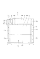
前記冷却装置6は、四角枠状のフレーム部材9に複数の熱交換器を組み込んでユニット化したものであって、本実施の形態では、本発明の下段熱交換器に相当する熱交換器として、エンジン冷却水を冷却するためのラジエータ10と、作動油を冷却するためのオイルクーラー11とが設けられており、また、本発明の上段熱交換器に相当する熱交換器として、エンジンの過給機で圧縮された空気を冷却するためのインタークーラー12が設けられている。そして、これらラジエータ10、オイルクーラー11、インタークーラー12が組み込まれた冷却装置6は、機械室7に設けられた冷却装置収納部7aに収納されているとともに、冷却装置6の背面側に配置された冷却ファン13の回転により流入する冷却風によって冷却されるように構成されている。また、冷却装置収納部7aの上方および正面側は、開閉自在な側面カバー(図示せず)によって覆蓋されており、該側面カバーに形成された通気孔から外気が導入されるとともに、側面カバーを開いて冷却装置6のメンテナンス等を行うことができるようになっている。尚、本実施の形態の説明において、冷却風の流れに対して上流側を冷却装置6の正面とし、下流側を背面とする。
The
ここで、前記ラジエータ10、オイルクーラー11、インタークーラー12は、被冷却流体(ラジエータ10ではエンジン冷却水、オイルクーラー11では作動油、インタークーラー12では圧縮空気)が流入する流入側タンク10a、11a、12aと、被冷却流体が流出する流出側タンク10b、11b、12bと、これら流入側タンク10a、11a、12aと流出側タンク10b、11b、12bとの間に設けられ、被冷却流体が通過する複数のチューブ及び冷却フィンを有するコア10c、11c、12cとを備えた汎用の構成のものであるが、本実施の形態では、これらラジエータ10、オイルクーラー11、インタークーラー12は、流入側タンク10a、11a、12aおよび流出側タンク10b、11b、12bがコア10c、11c、12cの左右に設けられ、被冷却流体が左右方向に流れるサイドフロー型のものが用いられている。
Here, the
そして、前記ラジエータ10、オイルクーラー11、インタークーラー12は、下段熱交換器であるラジエータ10およびオイルクーラー11が、ラジエータ10が下側に位置しオイルクーラー11が上側に位置する状態で、冷却風の流れに対して上下に並列する状態で配され、さらにこれら下段熱交換器の上側(本実施の形態では下側熱交換器のうち上側に位置するオイルクーラー11の上側)に、上段熱交換器であるインタークーラー12が、冷却風の流れに対して下段熱交換器と上下に並列する状態で配されている。この場合に、下段熱交換器であって上下に並列状に配されるラジエータ10およびオイルクーラー11の横幅は、略同寸法に設定されているとともに、上段熱交換器であるインタークーラー12の横幅は、ラジエータ10、オイルクーラー11の横幅よりも短く設定されており、これにより、インタークーラー12の横方に、後述するリザーバータンク14が配設されるタンク用スペースSが形成されている。そして、ラジエータ10、オイルクーラー11、インタークーラー12が組み込まれるフレーム部材9の上側隅部には、前記タンク用スペースSを区画するための段差状凹部9a(フレーム部材段差状凹部9a)が形成されている。
The
ここで、前記上段熱交換器としては、ラジエータ10以外の何れかの熱交換器を選択できるが、本実施の形態では、油圧ショベル1等の建設機械ではラジエータ10やオイルクーラー11に比して放熱面積が小さく、且つ、エンジンの上部に設けられるエンジン吸気側部品(過給機、吸気マニホールド)に接続されるインタークーラー12を上段熱交換器としている。そして、前述したように、該上段熱交換器であるインタークーラー12の横方にタンク用スペースSが形成されることになるが、該タンク用スペースSを含めた状態で、ユニット化された状態の冷却装置6が略正方形状となるように各熱交換器(ラジエータ10、オイルクーラー11、インタークーラー12)の縦横寸法が設定されている。
Here, any one of the heat exchangers other than the
一方、16は前記冷却ファン13の外周側を囲うファンシュラウドであって、該ファンシュラウド16は、前記ラジエータ10、オイルクーラー11、インタークーラー12が組付けられる四角枠状のフレーム部材9の背面側に連結されており、該ファンシュラウド16によって、冷却風の流れを整えて冷却効率を向上させることができるようになっているが、該ファンシュラウド16の上側隅部には、前記フレーム部材段差状凹部9aと連続する状態で、タンク用スペースSを区画するための段差状凹部16a(シュラウド段差状凹部16a)が形成されている。そして、これらフレーム部材段差状凹部9aおよびシュラウド段差状凹部16aにより区画されたタンク用スペースSに、ブラケット15を介してリザーバータンク14が配設される構成になっている。この場合に、フレーム部材9,ファンシュラウド16において段差状凹部9a、16aが形成される部分は、図3に示すように冷却ファン13のファン回転軌跡から遠い位置に位置していて、冷却効率への影響が殆ど無いうえ、フレーム部材9,ファンシュラウド16の段差状凹部9a、16aによってリザーバータンク14を冷却風から遮蔽することができるようになっている。
尚、図中、17aはラジエータ10の流入側タンク10aに接続されるラジエータ流入側配管、17bはラジエータ10の流出側タンク10bに接続されるラジエータ流出側配管、18aはオイルクーラー11の流入側タンク11aに接続されるオイルクーラー流入側配管、18bはオイルクーラー11の流出側タンク11bに接続されるオイルクーラー流出側配管、19aはインタークーラー12の流入側タンク12aに接続されるインタークーラー流入側配管、19bはインタークーラー12の流出側タンク12bに接続されるインタークーラー流出側配管である。
On the other hand, 16 is a fan shroud that surrounds the outer peripheral side of the cooling
In the figure, 17a is a radiator inflow side pipe connected to the
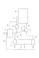
次いで、本実施の形態におけるエンジン冷却水循環系について、図4に基づいて説明する。図4において、10は前記ラジエータ、10a、10b、10cはラジエータ10の流入側タンク、流出側タンク、コア、14は前記リザーバータンク、20はエンジン(エンジンに設けられるウォータージャケット)、21はウォーターポンプ、22はサーモスタットである。そして、エンジン冷却水は、前記エンジン20とラジエータ10との間を密閉、且つ圧力を掛けられた状態で循環する。つまり、エンジン20から流出したエンジン冷却水は、エンジン出口側通路23、サーモスタット22、ラジエータ流入側配管17aを経由してラジエータ10に流入し、該ラジエータ10により冷却された後、ラジエータ流出側配管17bを経由してウォーターポンプ21に至り、該ウォーターポンプ21からエンジン入口側通路24を経由してエンジン20に供給される。また、前記サーモスタット22とウォーターポンプ21との間にはバイパス通路25が設けられており、エンジン冷却水温度が低い場合は、エンジン20から流出したエンジン冷却水はラジエータ10を経由することなく、サーモスタット22からバイパス通路25を経由してウォーターポンプ21に至ってエンジン20に供給されるようになっている。
Next, the engine coolant circulation system in the present embodiment will be described with reference to FIG. In FIG. 4, 10 is the radiator, 10a, 10b, 10c are the inflow side tank and outflow side tank of the
さらに、リザーバータンク14は、前記ラジエータ10とエンジンとの間の冷却水循環系に、ラジエータ10と並列状に接続されている。つまり、リザーバータンク14は、内部にエンジン冷却水の一部を貯留する液相部と該液相部の上方の気相部とを有し、エンジン冷却水の温度変化に伴う体積変化に応じてエンジン冷却水の貯留量を変化させる加圧密閉式のものであって、エンジン側ベント通路26、ラジエータ側ベント通路27を介してエンジン出口側通路23、ラジエータ10の流入側タンク10aにそれぞれ接続されるとともに、分岐通路28を介してウォーターポンプ21に接続されている。そして、このリザーバータンク14を経由してエンジン冷却水の一部が循環するとともに、リザーバータンク14内においてエンジン冷却水中のエア抜きがなされるようになっている。尚、14aは前記リザーバータンク14の注水口を塞ぐためのタンクキャップであって、該タンクキャップ14aは圧力調整機能を有しており、リザーバータンク14内の圧力が予め設定される上限圧力以上となった場合に該圧力をドレン通路29を介して冷却水循環系外に排出するようになっている。
Further, the
そして、前記リザーバータンク14は、冷却水循環系内においてエア抜きを行うため冷却水循環系内の最高位に配置する必要があり、このためラジエータ10の上端位置よりもリザーバータンク14を高位に配さなければならないが、前述したように、リザーバータンク14は上段熱交換器であるインタークーラー12の横方のタンク用スペースSに配されているため、下段熱交換器であるラジエータ10よりも高位に位置するようになっている。
The
叙述の如く構成された本形態において、油圧ショベル1の冷却システムは、複数の熱交換器としてラジエータ10、オイルクーラー11、インタークーラー12が設けられているとともに、これら複数の熱交換器(ラジエータ10、オイルクーラー11、インタークーラー12)に冷却風を供給する冷却ファン13、ラジエータ10とエンジンとの間の冷却水循環系にラジエータ10と並列状に接続される加圧密閉式のリザーバータンク14等を備えて構成されているが、このものにおいて、前記複数の熱交換器は、ラジエータ10以外の熱交換器であるインタークーラー12を上段熱交換器とし、該上段熱交換器以外のラジエータ10およびオイルクーラー11を下段熱交換器として上段熱交換器の下方に配設するとともに、該配設された状態での上段熱交換器全体の横幅は下段熱交換器全体の横幅よりも短く設定されていて、上段熱交換器の横方にタンク用スペースSが形成されている。そして、該タンク用スペースSに前記リザーバータンク14が配設されることになる。
In the present embodiment configured as described, the cooling system of the excavator 1 is provided with a
このように本発明が実施されたものにおいては、ラジエータ10を下段熱交換器とし、該下段熱交換器の上方に配される上段熱交換器の横方に形成したタンク用スペースSにリザーバータンク14を配することで、該リザーバータンク14を、ラジエータ10の上端位置よりも高位で、且つ、熱交換器全体から上方に突出しない状態で配設できることになる。この結果、ラジエータ10とエンジンとの間の冷却水循環系にラジエータ10と並列状に接続される加圧密閉式のリザーバータンク14であっても、該リザーバータンク14を熱交換器全体から上方に突出することなく配設できることになり、而して、熱交換器が収納される冷却装置収納部7aの天井高さを抑えることができて、リザーバータンク14に起因して冷却装置収納部7aの天井高さが高くなり運転室5からの後方視界が悪化してしまうことを回避できる。
Thus, in the embodiment of the present invention, the
しかもこのものにおいて、下段熱交換器であるラジエータ10とオイルクーラー11とは、冷却ファン13により供給される冷却風の流れに対して上下に並列する状態で配され、上段熱交換器であるインタークーラー12は、ラジエータ10およびオイルクーラー11に対して上下に並列する状態で配されている。而して、ラジエータ10を含む複数の熱交換器は、冷却風の流れに対して互いに重ならない状態で配されることになって、良好な冷却効率を確保できるとともに、清掃等のメンテナンス性に優れる。
In addition, the
また、本実施の形態では、複数の熱交換器として、油圧ショベル1等の建設機械に汎用的に設けられる熱交換器であるラジエータ10とオイルクーラー11とインタークーラー12とが設けられているが、上段熱交換器であるインタークーラー12は、一般的に下段熱交換器であるラジエータ10やオイルクーラー11に比して放熱面積の小さいものが用いられるため、横幅を短くしても冷却効率への影響は殆ど無く、さらに、インタークーラー12の流入側、流出側配管19a、19bはエンジンの上部に設けられるエンジン吸気側部品(過給機、吸気マニホールド)に接続されるため、インタークーラー12を上段熱交換器とすることによって、エンジン吸気側部品に接続されるインタークーラー12の流入側、流出側配管19a、19bを短くできるという利点もある。
In the present embodiment, as a plurality of heat exchangers, a
さらにこのものにおいて、上段熱交換器(インタークーラー12)および下段熱交換器(ラジエータ10およびオイルクーラー11)は、冷却装置6としてユニット化されて四角枠状のフレーム部材9に組み込まれるが、該フレーム部材9には冷却ファン13を囲うファンシュラウド16が連結されるとともに、フレーム部材9およびファンシュラウド16の上側隅部には、リザーバータンク14が配設されるタンク用スペースSを区画する段差状凹部9a、16aが形成されている。而して、該段差状凹部9a、16aによってリザーバータンク14を冷却風から遮蔽することができるとともに、段差状凹部9a、16aが形成されるフレーム部材9およびファンシュラウド16の上側隅部は、冷却ファン13のファン回転軌跡から遠い位置であるため、冷却効率への影響を可及的に少なくすることができる。
Further, in this device, the upper heat exchanger (intercooler 12) and the lower heat exchanger (
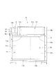
尚、本発明は前記実施の形態(第一の実施の形態)に限定されないことは勿論であって、図5に示す第二の実施の形態の如く、下段熱交換器であるラジエータ10とオイルクーラー10とを、冷却風の流れに対して左右に並列する状態で配することもできる。このように下段熱交換器同士を左右に並列状に配設しても、上段熱交換器であるインタークーラー12の横方のタンク用スペースSに配されたリザーバータンク14は、下段熱交換器であるラジエータ10の上端部よりも高位に位置することになって、前述した第一の実施の形態と同様の作用効果を奏する。尚、図5には、下段熱交換器であるラジエーター10、オイルクーラー11として、流入側タンク10a、11a、流出側タンク10b、11bがコア10c、11cの上下に設けられるダウンフロー型のものを図示したが、第二の実施の形態のものにおいても、第一の実施の形態のようにサイドフロー型のラジエーター、オイルクーラーとすることもできる。因みに、加圧密閉式のリザーバータンク14を用いる場合は、注水口はリザーバータンク14に設けられていてラジエータ10には設けられないため、ダウンフロー式のラジエータ10を用いても、その上側に上段熱交換器を配設することが可能となる。
Of course, the present invention is not limited to the above-described embodiment (first embodiment), and as in the second embodiment shown in FIG. The cooler 10 can also be arranged in a state of being parallel to the left and right with respect to the flow of the cooling air. Thus, even if the lower heat exchangers are arranged in parallel on the left and right, the
さらに、前記第一、第二の実施の形態では上段熱交換器をインタークーラーとしたが、上段熱交換器はラジエータ以外の熱交換器であればインタークーラーに限定されるとこなく、例えば空調用コンデンサを上段熱交換器とすることもできる。また、上段熱交換器、下段熱交換器は単数でも複数でも良く、さらに、上段熱交換器および下段熱交換器に加えて、これら上段熱交換器、下段熱交換器と冷却風の流れに対して重なる他の熱交換器が設けられている場合であっても、本発明を実施できる。
また、本発明は、油圧ショベルに限定されることなく、各種建設機械に実施できることは勿論である。
Furthermore, in the first and second embodiments, the upper heat exchanger is an intercooler. However, the upper heat exchanger is not limited to an intercooler as long as it is a heat exchanger other than a radiator. It can also be set as an upper stage heat exchanger. In addition to the upper heat exchanger and the lower heat exchanger, the upper heat exchanger and the lower heat exchanger may be single or plural, and in addition to the upper heat exchanger, the lower heat exchanger, and the flow of the cooling air, The present invention can be implemented even when other heat exchangers overlapping each other are provided.
Of course, the present invention is not limited to hydraulic excavators, and can be implemented in various construction machines.
本発明は、ラジエータを含む複数の熱交換器や、冷却ファン、リザーバータンク等を備えた建設機械の冷却システムに利用することができる。 INDUSTRIAL APPLICABILITY The present invention can be used for a cooling system for a construction machine including a plurality of heat exchangers including a radiator, a cooling fan, a reservoir tank, and the like.
1 油圧ショベル
9 フレーム部材
9a 段差状凹部
10 ラジエータ
11 オイルクーラー
12 インタークーラー
13 冷却ファン
14 リザーバータンク
16 ファンシュラウド
16a 段差状凹部
S タンク用スペース
DESCRIPTION OF SYMBOLS 1 Hydraulic excavator 9
Claims (4)
Priority Applications (6)
| Application Number | Priority Date | Filing Date | Title |
|---|---|---|---|
| JP2016076995A JP6730766B2 (en) | 2016-04-07 | 2016-04-07 | Arrangement structure of cooling system in construction machinery |
| DE112017001248.1T DE112017001248T5 (en) | 2016-04-07 | 2017-04-03 | ARRANGEMENT STRUCTURE OF A COOLING SYSTEM IN CONSTRUCTION MACHINES |
| PCT/EP2017/057873 WO2017174520A1 (en) | 2016-04-07 | 2017-04-03 | Arrangement structure of cooling system in construction equipment |
| KR1020187030192A KR102402533B1 (en) | 2016-04-07 | 2017-04-03 | Layout structure of construction equipment cooling system |
| US16/086,222 US20200291845A1 (en) | 2016-04-07 | 2017-04-03 | Arrangement Structure of Cooling System in Construction Equipment |
| CN201780021104.2A CN109072580B (en) | 2016-04-07 | 2017-04-03 | Arrangement structure of cooling system in construction equipment |
Applications Claiming Priority (1)
| Application Number | Priority Date | Filing Date | Title |
|---|---|---|---|
| JP2016076995A JP6730766B2 (en) | 2016-04-07 | 2016-04-07 | Arrangement structure of cooling system in construction machinery |
Publications (2)
| Publication Number | Publication Date |
|---|---|
| JP2017185931A true JP2017185931A (en) | 2017-10-12 |
| JP6730766B2 JP6730766B2 (en) | 2020-07-29 |
Family
ID=58488995
Family Applications (1)
| Application Number | Title | Priority Date | Filing Date |
|---|---|---|---|
| JP2016076995A Active JP6730766B2 (en) | 2016-04-07 | 2016-04-07 | Arrangement structure of cooling system in construction machinery |
Country Status (6)
| Country | Link |
|---|---|
| US (1) | US20200291845A1 (en) |
| JP (1) | JP6730766B2 (en) |
| KR (1) | KR102402533B1 (en) |
| CN (1) | CN109072580B (en) |
| DE (1) | DE112017001248T5 (en) |
| WO (1) | WO2017174520A1 (en) |
Cited By (1)
| Publication number | Priority date | Publication date | Assignee | Title |
|---|---|---|---|---|
| JP2022055944A (en) * | 2020-09-29 | 2022-04-08 | コベルコ建機株式会社 | Work machine |
Families Citing this family (2)
| Publication number | Priority date | Publication date | Assignee | Title |
|---|---|---|---|---|
| US11492954B2 (en) * | 2020-08-06 | 2022-11-08 | Illinois Tool Works Inc. | Power systems and enclosures having configurable air flow |
| DE102020212791A1 (en) | 2020-10-09 | 2022-04-14 | Mahle International Gmbh | vehicle cooling system |
Citations (6)
| Publication number | Priority date | Publication date | Assignee | Title |
|---|---|---|---|---|
| JPH02122116U (en) * | 1989-03-16 | 1990-10-05 | ||
| JP2001341533A (en) * | 2000-06-02 | 2001-12-11 | Shin Caterpillar Mitsubishi Ltd | Cooling device for construction machine |
| JP2003049649A (en) * | 2001-08-03 | 2003-02-21 | Shin Caterpillar Mitsubishi Ltd | Construction equipment |
| US20050079051A1 (en) * | 2003-10-14 | 2005-04-14 | Fred Soofer | Vehicle fan shroud made integrally with a coolant reservoir |
| JP2013024200A (en) * | 2011-07-25 | 2013-02-04 | Hino Motors Ltd | Engine cooler |
| JP2014114763A (en) * | 2012-12-11 | 2014-06-26 | Hitachi Constr Mach Co Ltd | Construction machine |
Family Cites Families (12)
| Publication number | Priority date | Publication date | Assignee | Title |
|---|---|---|---|---|
| DE3922814A1 (en) * | 1988-09-30 | 1990-04-12 | Piemontese Radiatori | Mounting frame for motor vehicle radiator - has slide mounting cooling block and fittings for condenser and oil cooler |
| US5197538A (en) * | 1991-04-22 | 1993-03-30 | Zexel Corporation | Heat exchanger apparatus having fluid coupled primary heat exchanger unit and auxiliary heat exchanger unit |
| JP2907018B2 (en) * | 1994-09-06 | 1999-06-21 | トヨタ自動車株式会社 | Mounting structure of tank in radiator |
| DE19514016C1 (en) * | 1995-04-13 | 1996-08-29 | Laengerer & Reich Gmbh & Co | Radiator unit for vehicle |
| JPH09112268A (en) * | 1995-10-19 | 1997-04-28 | Hitachi Constr Mach Co Ltd | Engine cooling device and construction equipment |
| JPH11190046A (en) * | 1997-12-25 | 1999-07-13 | Yutani Heavy Ind Ltd | Hydraulic shovel |
| US6622783B2 (en) * | 2001-08-14 | 2003-09-23 | Modine Manufacturing Company | Self-fixturing fan shroud |
| DE10322211A1 (en) * | 2003-05-16 | 2004-12-02 | Modine Manufacturing Co., Racine | heat exchanger block |
| JP4430467B2 (en) * | 2004-07-02 | 2010-03-10 | 日立建機株式会社 | Construction machine cooling system |
| JP5821221B2 (en) * | 2011-03-08 | 2015-11-24 | コベルコ建機株式会社 | Construction machine cooling system |
| BR102015026378A2 (en) * | 2014-10-21 | 2017-07-11 | Modine Manufacturing Company | COOLING MODULE WITH A TANK OF INTEGRATED COMPENSATION TO HIM |
| JP6401016B2 (en) * | 2014-10-31 | 2018-10-03 | 日立建機株式会社 | Construction machinery |
-
2016
- 2016-04-07 JP JP2016076995A patent/JP6730766B2/en active Active
-
2017
- 2017-04-03 KR KR1020187030192A patent/KR102402533B1/en active IP Right Grant
- 2017-04-03 CN CN201780021104.2A patent/CN109072580B/en active Active
- 2017-04-03 DE DE112017001248.1T patent/DE112017001248T5/en active Pending
- 2017-04-03 WO PCT/EP2017/057873 patent/WO2017174520A1/en active Application Filing
- 2017-04-03 US US16/086,222 patent/US20200291845A1/en active Pending
Patent Citations (6)
| Publication number | Priority date | Publication date | Assignee | Title |
|---|---|---|---|---|
| JPH02122116U (en) * | 1989-03-16 | 1990-10-05 | ||
| JP2001341533A (en) * | 2000-06-02 | 2001-12-11 | Shin Caterpillar Mitsubishi Ltd | Cooling device for construction machine |
| JP2003049649A (en) * | 2001-08-03 | 2003-02-21 | Shin Caterpillar Mitsubishi Ltd | Construction equipment |
| US20050079051A1 (en) * | 2003-10-14 | 2005-04-14 | Fred Soofer | Vehicle fan shroud made integrally with a coolant reservoir |
| JP2013024200A (en) * | 2011-07-25 | 2013-02-04 | Hino Motors Ltd | Engine cooler |
| JP2014114763A (en) * | 2012-12-11 | 2014-06-26 | Hitachi Constr Mach Co Ltd | Construction machine |
Cited By (2)
| Publication number | Priority date | Publication date | Assignee | Title |
|---|---|---|---|---|
| JP2022055944A (en) * | 2020-09-29 | 2022-04-08 | コベルコ建機株式会社 | Work machine |
| JP7472743B2 (en) | 2020-09-29 | 2024-04-23 | コベルコ建機株式会社 | Work Machine |
Also Published As
| Publication number | Publication date |
|---|---|
| CN109072580B (en) | 2021-07-20 |
| JP6730766B2 (en) | 2020-07-29 |
| US20200291845A1 (en) | 2020-09-17 |
| CN109072580A (en) | 2018-12-21 |
| DE112017001248T5 (en) | 2018-12-13 |
| WO2017174520A1 (en) | 2017-10-12 |
| KR20180133428A (en) | 2018-12-14 |
| KR102402533B1 (en) | 2022-05-27 |
Similar Documents
| Publication | Publication Date | Title |
|---|---|---|
| JP6730766B2 (en) | Arrangement structure of cooling system in construction machinery | |
| US9512773B2 (en) | Cooling apparatus for construction machine | |
| KR20160124101A (en) | Compact unit comprising an electric motor and hydraulic pump | |
| JP2016113812A (en) | Arrangement structure of reducing agent tank on construction machine | |
| CN104053963A (en) | Heat Exchanger, In Particular For A Motor Vehicle, And Corresponding Air Intake Device | |
| JP4730403B2 (en) | Heat exchange equipment for construction machinery | |
| JP7065642B2 (en) | Work machine | |
| CN202081958U (en) | Auxiliary water tank and engine cooling system | |
| JP4825700B2 (en) | Reserve tank and engine cooling device equipped with the same | |
| JP4890286B2 (en) | Reserve tank and engine cooling device equipped with the same | |
| JPWO2017068730A1 (en) | Cylinder head water jacket structure | |
| CA2943172C (en) | Package-storage type engine generator | |
| JP5917383B2 (en) | Construction machinery | |
| CN206592195U (en) | Engine water pump water route integrated housing | |
| CN205387970U (en) | A add water stand subassembly and operation machinery for operation machine cooling package | |
| WO2017209145A1 (en) | Expansion tank | |
| CN212427315U (en) | Construction machine | |
| JP6152605B2 (en) | Construction machinery | |
| KR20210107931A (en) | Inter Cooler | |
| JP3787053B2 (en) | Engine cooling system | |
| KR20210107930A (en) | Inter Cooler | |
| JP2014145166A (en) | Work machine | |
| JP4150628B2 (en) | Water-cooled engine thermostat housing | |
| JP2010249083A (en) | Cooling system of construction machine and heat exchanger used in the cooling system | |
| JP2005126990A (en) | Cooling device of working machine |
Legal Events
| Date | Code | Title | Description |
|---|---|---|---|
| A621 | Written request for application examination |
Free format text: JAPANESE INTERMEDIATE CODE: A621 Effective date: 20190204 |
|
| A977 | Report on retrieval |
Free format text: JAPANESE INTERMEDIATE CODE: A971007 Effective date: 20200210 |
|
| A131 | Notification of reasons for refusal |
Free format text: JAPANESE INTERMEDIATE CODE: A131 Effective date: 20200220 |
|
| A521 | Request for written amendment filed |
Free format text: JAPANESE INTERMEDIATE CODE: A523 Effective date: 20200514 |
|
| TRDD | Decision of grant or rejection written | ||
| A01 | Written decision to grant a patent or to grant a registration (utility model) |
Free format text: JAPANESE INTERMEDIATE CODE: A01 Effective date: 20200702 |
|
| A61 | First payment of annual fees (during grant procedure) |
Free format text: JAPANESE INTERMEDIATE CODE: A61 Effective date: 20200702 |
|
| R150 | Certificate of patent or registration of utility model |
Ref document number: 6730766 Country of ref document: JP Free format text: JAPANESE INTERMEDIATE CODE: R150 |
|
| R250 | Receipt of annual fees |
Free format text: JAPANESE INTERMEDIATE CODE: R250 |