JP4890286B2 - Reserve tank and engine cooling device equipped with the same - Google Patents
Reserve tank and engine cooling device equipped with the same Download PDFInfo
- Publication number
- JP4890286B2 JP4890286B2 JP2007026552A JP2007026552A JP4890286B2 JP 4890286 B2 JP4890286 B2 JP 4890286B2 JP 2007026552 A JP2007026552 A JP 2007026552A JP 2007026552 A JP2007026552 A JP 2007026552A JP 4890286 B2 JP4890286 B2 JP 4890286B2
- Authority
- JP
- Japan
- Prior art keywords
- tank
- tank body
- horizontal direction
- reserve tank
- storage chamber
- Prior art date
- Legal status (The legal status is an assumption and is not a legal conclusion. Google has not performed a legal analysis and makes no representation as to the accuracy of the status listed.)
- Expired - Fee Related
Links
Images


Description
本発明は、リザーブタンクおよび同タンクを備えたエンジン冷却装置、特に冷却液の上方に冷却液面変化に応じて体積変化する空気溜まりを形成するようにした密閉型のリザーブタンクおよびエンジン冷却装置に関する。 TECHNICAL FIELD The present invention relates to a reserve tank and an engine cooling device including the tank, and more particularly to a hermetic reserve tank and an engine cooling device that form an air reservoir that changes in volume according to a change in the coolant level above the coolant. .
内燃エンジン冷却装置に装備されるリザーブタンクには、その上部に形成された注水口を加圧密閉式のキャップで密閉し、内部に貯留した冷却水の上方に空気溜まりを形成して、冷却水(冷却液)の温度変化に伴う液面変化を空気溜まりの体積変化により吸収するようにした密閉型のものがある。 In the reserve tank equipped in the internal combustion engine cooling device, the water injection port formed in the upper part is sealed with a pressure-sealing cap, an air reservoir is formed above the cooling water stored inside, and the cooling water ( There is a hermetically sealed type in which a change in the liquid level accompanying a change in temperature of the coolant is absorbed by a change in the volume of the air pool.
また、このようなリザーブタンクは、エンジンからの冷却水の戻り側であるラジエータ上部に冷却水の出入りを許容するよう配管接続されるとともに、ラジエータ下部からエンジン内への冷却水の供給路側(以下、単にエンジン側という)に冷却水を供給するよう配管接続されているものが多い。 In addition, such a reserve tank is connected to the upper part of the radiator, which is the return side of the cooling water from the engine, by piping so as to allow the cooling water to enter and exit, and from the lower part of the radiator to the cooling water supply path side (hereinafter referred to as the cooling water supply path). Many of them are connected by piping so as to supply cooling water to the engine side.
従来のこの種のリザーブタンクとしては、そのタンク内部を隣り合う複数の貯留室に分割するよう下端部に連通孔を有する隔壁部を設け、その一端側の貯留室に主たる空気溜めを形成するようにしたものがあり、このリザーブタンクにおいては、ラジエータ側からの冷却水を出入りさせるラジエータ側の連通孔部をタンク上部側に開口させ、エンジン側に冷却水を供給するエンジン側の連通孔部をタンク下部側に開口させている(例えば、特許文献1参照)。 As a conventional reserve tank of this type, a partition wall having a communication hole is provided at the lower end so as to divide the inside of the tank into a plurality of adjacent storage chambers, and a main air reservoir is formed in the storage chamber on one end side thereof. In this reserve tank, a communication hole on the radiator side for allowing cooling water to enter and exit from the radiator side is opened on the upper side of the tank, and a communication hole on the engine side for supplying cooling water to the engine side is provided. It opens to the tank lower side (for example, refer patent document 1).
また、タンクの一端側の流入管と他端側の流出管の間に連通路を有する複数の隔壁部を設けて、長手方向に隣り合う複数の貯留室を形成したもの(例えば、特許文献2、3参照)や、タンク内に複数の平行な隔壁部を設けるとともにそれらの下端側および上端側に形成した連通孔を通して互いに隣り合う複数の貯留室を互いに連通させ、複数の貯留室に同一の液面高さで冷却水およびその上方の空気溜まりを貯留するようにしたものがある(例えば特許文献4参照)。 In addition, a plurality of partition walls having communication paths are provided between an inflow pipe on one end side and an outflow pipe on the other end side of the tank to form a plurality of storage chambers adjacent in the longitudinal direction (for example, Patent Document 2) 3), and a plurality of parallel partition walls provided in the tank and a plurality of adjacent storage chambers communicated with each other through communication holes formed on the lower end side and the upper end side thereof. There is one in which the cooling water and the air reservoir above it are stored at a liquid level (see, for example, Patent Document 4).
さらに、上下方向に圧縮可能なようにタンク本体の上下方向中間部に蛇腹部を有し、長手方向を車両前後方向に向けて車両のフェンダーの内方に配置されるようにしたものがあり、このリザーブタンクでは取付け高さの制約から前方部の高さが後方部の高さより低くなっている(例えば、特許文献5参照)。
しかしながら、上述のような従来のリザーブタンクおよびこれを備えた車両の冷却装置にあっては、車両に大きな横向き加速度(いわゆる横G)が作用するコーナリング時のような走行状態が比較的長く続くような場合に、エンジン側に供給する冷却水に空気が混入してしまうためにウォーターポンプ内でキャビテーションが発生し、エンジンの冷却性能が低下してしまうという問題があった。 However, in the conventional reserve tank as described above and the cooling device for a vehicle including the same, a traveling state such as cornering in which a large lateral acceleration (so-called lateral G) acts on the vehicle is maintained for a relatively long time. In such a case, air is mixed into the cooling water supplied to the engine side, so that cavitation occurs in the water pump, and the cooling performance of the engine is deteriorated.
すなわち、車両の急な加速や制動による短時間の液面変動であれば適当な連通孔を形成したバッフルプレート等の仕切りを入れることで回避できるが、大きな横向き加速度が比較的長い時間続くような走行状態になると、タンク内の液面が大きく傾斜してしまい、リザーブタンク内で冷却水中に開口させているエンジン側の連通孔部が液面から出て空気溜まりに通じてしまうことがあり、その場合、このエンジン側の連通孔部を通しエンジン側に供給する冷却水に空気が混入してしまうために、冷却性能の低下を招いていた。 In other words, if the liquid level fluctuates for a short time due to sudden acceleration or braking of the vehicle, it can be avoided by inserting a partition such as a baffle plate with an appropriate communication hole, but large lateral acceleration continues for a relatively long time. When the vehicle is in a running state, the liquid level in the tank is greatly inclined, and the communication hole on the engine side opened in the cooling water in the reserve tank may come out of the liquid level and lead to an air reservoir. In that case, since air is mixed into the cooling water supplied to the engine side through the communication hole portion on the engine side, the cooling performance is lowered.
そのため、従来のリザーブタンクおよびこれを備えた車両の冷却装置にあっては、例えばサーキット走行時のように上述の液面傾斜が顕著になるような場合に対応できなかった。 For this reason, the conventional reserve tank and the cooling device for a vehicle including the same cannot cope with a case where the above-described liquid level inclination becomes significant, for example, during circuit running.
また、ラジエータ内の圧力上昇時にリザーブタンク内に冷却水を戻すためのラジエータ側の連通孔部をタンクの上部側に開口させていたため、ラジエータ側の連通孔部をエンジン側の連通孔部から離隔させて冷却水中への空気混入を防止する必要から、リザーブタンクの高さを低く抑えることが容易でないばかりか、リザーブタンク側からの冷却水の戻りが悪くなるためにラジエータ側の内圧上昇に耐え得るようタンク強度を高める必要があった。そのため、リザーブタンクのレイアウト面やコスト面でも問題があった。 In addition, the radiator side communication hole for returning the cooling water into the reserve tank when the pressure in the radiator increases is opened to the upper side of the tank, so the radiator side communication hole is separated from the engine side communication hole. Therefore, it is not easy to keep the height of the reserve tank low because it is necessary to prevent air from entering the cooling water, and the return of cooling water from the reserve tank side becomes worse, so it can withstand the rise in internal pressure on the radiator side. It was necessary to increase the strength of the tank to obtain it. For this reason, there are problems with the layout and cost of the reserve tank.
そこで、本発明は、タンク高さを抑えても、大きな加速度が作用するような走行状態下でエンジン側への冷却液中に空気が混入するのを確実に防止することができる低コストのリザーブタンクを提供することを目的とする。 Therefore, the present invention provides a low-cost reserve that can reliably prevent air from being mixed into the coolant to the engine side under traveling conditions in which a large acceleration acts even if the tank height is suppressed. The purpose is to provide a tank.
上記目的達成のため、本発明は、(1)ラジエータ側に水平方向一方側の下部で配管接続されるとともに上部に冷却液を注入する注入口が形成され、前記冷却液をその上方の空気溜まりと共に貯留するタンク本体と、前記注入口を密閉するキャップと、を備えた密閉型のリザーブタンクにおいて、前記タンク本体が、前記タンク本体の水平方向他方側の下部で前記水平方向一方側の下部から離隔する方向に膨出した膨出部と、前記タンク本体の内底面から上方に突出するとともに前記タンク本体内を前記水平方向一方側に位置する一方側の貯留室と前記水平方向他方側に位置する他方側の貯留室とに区画する隔壁部とを有し、前記隔壁部が、前記タンク本体内の下部側で前記一方側の貯留室と前記他方側の貯留室とを連通させる下部連通孔と、前記タンク本体の上部内で前記一方側の貯留室と前記他方側の貯留室とを連通させる上部連通孔とを形成しているとともに、前記タンク本体の下部で前記一方側の貯留室が、前記ラジエータの冷却液の戻り側と供給側に対応する一対の室に区画されるとともに、該一対の室が前記ラジエータの冷却液の戻り側と供給側に連通するよう、前記タンク本体の下部に前記一対の室に対応する一対の連通孔が形成されていることを特徴とする。 In order to achieve the above object, the present invention provides: (1) A pipe is connected to the radiator at the lower part on one side in the horizontal direction, and an inlet for injecting a cooling liquid is formed at the upper part. a tank body for storing together with a cap for sealing the inlet, the reservoir tank of the closed type equipped with the tank body, the lower portion of the horizontal one side at the bottom of the horizontal other side of the tank body A bulging portion that bulges in a separating direction, and projects upward from the inner bottom surface of the tank body, and is located on one side of the storage space on the one side in the horizontal direction and on the other side in the horizontal direction. A lower partition hole that partitions the first storage chamber and the second storage chamber on a lower side in the tank body. When Together form an upper communication hole for communicating the storage chamber of the one said a storage chamber side the other side in the upper portion of the tank body, said one side of the storage chamber at the bottom of the tank body, the while being divided into a pair of chambers with coolant return side of the radiator corresponding to the supply side, so that the pair of chambers communicates with the supply side and the return side of the cooling liquid of the radiator, the lower portion of the tank body A pair of communication holes corresponding to the pair of chambers are formed.
このリザーブタンクでは、運転時にリザーブタンク内の冷却液面が比較的長時間傾斜しても、その液面はリザーブタンクの下部に比較して水平断面積の狭い上部内に制限されることから、ラジエータ側に配管接続された水平方向一方側の下部が液面上に露出することなく、その水平方向一方側の下部の液中配置状態が維持されることになる。また、隔壁部がバッフルプレートともなり、比較的短時間の液面傾斜に対しては水平方向一方側の貯留室の液面高さをより高く維持するのに寄与し得る。さらに、タンク本体の水平方向一方側の下部でラジエータ側への配管接続がなされ、液面も低く抑えられることから、ラジエータの内圧上昇を抑えることができる。しかも、膨出部によりタンク下部に十分な冷却液貯留量を確保することで、タンク高さを抑えても、複数の貯留室に一様な圧力の空気溜まりを形成することができ、タンク本体の上部内に所要の空気溜まりを形成することができる。加えて、ラジエータ側からの冷却液の戻りを許容しつつエンジン側に冷却液を供給することが可能なリザーブタンクとなる。なお、前記水平方向一方側の下部から離隔する方向とは、前記水平方向の一方側から他方側に向かう方向のみならず、それと交差する略水平方向であってもよい。 In this reserve tank, even if the coolant level in the reserve tank is inclined for a relatively long time during operation, the liquid level is limited to the upper part of the horizontal cross-sectional area narrower than the lower part of the reserve tank. The lower portion on one side in the horizontal direction connected by piping to the radiator side is not exposed on the liquid surface, and the in-liquid arrangement state of the lower portion on one side in the horizontal direction is maintained. Further, the partition wall portion also serves as a baffle plate, and can contribute to maintaining the liquid level height of the storage chamber on one side in the horizontal direction higher with respect to the liquid level inclination for a relatively short time. Furthermore, since the pipe connection to the radiator side is made at the lower part on one side in the horizontal direction of the tank body and the liquid level is also kept low, it is possible to suppress an increase in the internal pressure of the radiator. Moreover, by securing a sufficient amount of coolant storage in the lower part of the tank by the bulging part, even if the tank height is suppressed, an air pool with uniform pressure can be formed in a plurality of storage chambers. The required air reservoir can be formed in the upper part of the slab. In addition, the reserve tank can supply the coolant to the engine side while allowing the coolant to return from the radiator side. Incidentally, a direction away from the bottom of the horizontal one side, the not from one side of the horizontal direction only toward the other side, at the same or may be substantially horizontal direction crossing.
本発明のリザーブタンクは、好ましくは、(2)前記隔壁部が、前記一方側の貯留室を前記一対の室に区画するよう前記タンク本体内で前記水平方向一方側に向かって突出する突出壁部を有するとともに、前記タンク本体内の下部側で前記一対の室と前記他方側の貯留室とを連通させる下部連通孔と、前記タンク本体の上部内で前記一対の室と前記他方側の貯留室とを連通させる上部連通孔とを有していることを特徴とするものである。 Reserve tank of the present invention, preferably, (2) projecting wall the dividing walls, which protrude toward the horizontal direction on one side of the storage chamber of the one side in the tank body so as to partition the pair of chambers And a lower communication hole that communicates the pair of chambers with the other storage chamber on the lower side in the tank body, and the pair of chambers and the other storage in the upper portion of the tank body. and it is characterized in that it has an upper communicating hole for communicating the chamber.
この構成により、一対の連通孔を確実に液中に配置することができ、しかも、ラジエータ側からの冷却液に含まれる気泡がエンジン側に供給される冷却液に混入するのを隔壁部により防止することができる。 With this configuration, the pair of communication holes can be reliably disposed in the liquid, and air bubbles contained in the cooling liquid from the radiator side are prevented from entering the cooling liquid supplied to the engine side by the partition wall. can do.
上記(1)または(2)の構成を有するリザーブタンクにおいては、(3)前記水平方向一方側および前記水平方向他方側を車両の左右方向に向けて前記車両に搭載されるのが望ましい。 In the reserve tank having the above configuration (1) or (2), (3) it is desirable that the reserve tank is mounted on the vehicle with the one side in the horizontal direction and the other side in the horizontal direction directed in the left-right direction of the vehicle.
これにより、大きな横向き加速度が作用するコーナリング時のような走行状態が比較的長く続くような場合でも、ラジエータ側あるいは更にエンジン側に配管接続された水平方向一方側の下部の液中配置状態を維持することができる。 This maintains the submerged arrangement of the lower part on one side in the horizontal direction that is connected to the radiator side or further to the engine side, even when the running state during cornering where a large lateral acceleration acts is relatively long. can do.
上記(1)〜(3)の何れかの構成を有するリザーブタンクにおいては、(4)前記タンク本体の上部の前記水平方向における内幅が前記注入口の内径よりも大きいのが好ましい。 In the reserve tank having any one of the configurations (1) to (3), it is preferable that (4) the inner width in the horizontal direction of the upper portion of the tank body is larger than the inner diameter of the injection port.
この場合、注水作業性が良好となる。 In this case, water injection workability is improved.
また、上記(1)〜(4)の何れかの構成を有するリザーブタンクにおいては、(5)前記タンク本体の内底面からの前記膨出部の内面高さが、前記タンク本体の内底面からの前記冷却液の注入時液面高さの許容範囲より上方に位置するのがよい。 Moreover, in the reserve tank which has a structure in any one of said (1)-(4), (5) The inner surface height of the said bulging part from the inner bottom face of the said tank main body is from the inner bottom face of the said tank main body. It is preferable to be positioned above the permissible range of the liquid level when the coolant is injected.
これにより、空気溜りを十分に形成することができる。なお、前記膨出部の内面高さは、ラジエータ側からの冷却液の戻りにより液面が上昇するときには、その液面近傍かあるいはその液面より下方に位置するようにすることができる。 Thereby, an air pocket can fully be formed. The height of the inner surface of the bulging portion can be positioned near or below the liquid level when the liquid level rises due to the return of the cooling liquid from the radiator side.
上記(1)〜(5)の何れかの構成を有するリザーブタンクにおいては、(6)前記注入口が、前記冷却液を前記他方側の貯留室に導入するよう前記隔壁部に対し前記水平方向他方側に形成されていてもよい。 In the reserve tank having any one of the constitutions (1) to (5), (6) the injection port is arranged in the horizontal direction with respect to the partition wall so as to introduce the cooling liquid into the storage chamber on the other side. It may be formed on the other side .
一方、本発明のエンジン冷却装置は、(7)上記(1)〜(6)の何れかの構成を有するリザーブタンクと、前記ラジエータと、前記冷却液をエンジン内および前記ラジエータ内を通して循環させるウォーターポンプと、を備えている。 On the other hand, the engine cooling device of the present invention comprises (7) a reserve tank having any one of the constitutions (1) to (6), the radiator, and water for circulating the coolant through the engine and the radiator. And a pump.
この構成により、エンジンの運転時に水平方向他方側に向かう加速度がリザーブタンクに作用し、リザーブタンク内に貯留された冷却液の液面が水平方向一方側に傾斜しても、その液面はリザーブタンクの下部に比較して水平断面積の狭い上部内に制限され、ラジエータ側に配管接続された水平方向他方側の下部が液面上に露出することなくその液中配置状態を維持できることになる。したがって、リザーブタンクからエンジン側に供給される冷却水への空気の混入によってウォーターポンプ内でキャビテーションが発生し、エンジンの冷却性能が低下してしまうという問題が解消される。 With this configuration, the acceleration toward the other side in the horizontal direction during operation of the engine acts on the reserve tank, and even if the liquid level of the coolant stored in the reserve tank is tilted to one side in the horizontal direction, the liquid level remains in the reserve tank. It is limited to the upper part where the horizontal cross-sectional area is narrow compared with the lower part of the tank, and the lower part on the other side in the horizontal direction connected to the radiator side can be maintained in the liquid without being exposed on the liquid level. . Therefore, the problem that cavitation occurs in the water pump due to the mixing of air into the cooling water supplied from the reserve tank to the engine side, and the problem that the cooling performance of the engine deteriorates is solved.
上記(7)の構成を有するエンジン冷却装置は、(8)前記エンジンを搭載した車両に、前記リザーブタンクが長手方向の一端部および他端部を前記水平方向一方側および前記水平方向他方側となる前記車両の左右方向に向けた装着状態で装備されていることを特徴とするのがよい。 The engine cooling apparatus having the configuration of the above (7) includes: (8) a vehicle on which the engine is mounted , wherein the reserve tank has one end portion and the other end portion in the longitudinal direction at one side in the horizontal direction and the other side in the horizontal direction. It is good to be equipped with the mounting | wearing state toward the left-right direction of the said vehicle.
この構成により、大きな横向き加速度が作用するコーナリング時のような走行状態が比較的長く続くような場合でも、ラジエータ側あるいは更にエンジン側に配管接続された水平方向一方側の下部の液中配置状態を維持することができる。 With this configuration, even when the running state such as cornering in which a large lateral acceleration is applied continues for a relatively long time, the submerged arrangement state of the lower part on one side in the horizontal direction connected to the radiator side or further to the engine side is maintained. Can be maintained.
本発明によれば、膨出部によりタンク下部に十分な冷却液貯留量を確保することで、タンク高さを抑えても所要の空気溜りを形成してエンジンの運転時におけるラジエータ側からの冷却液の戻りを確実に吸収させることができ、しかも、リザーブタンク内の冷却液面が傾斜したとしても、その液面をリザーブタンクの下部に比較して水平断面積の狭い上部内に制限し、かつ、隔壁部にバッフルプレート機能を持たせることで、ラジエータ側に配管接続された水平方向一方側の下部を液面上に露出させることなくその液中配置状態を確実に維持させることができる。さらに、水平方向一方側の下部でラジエータ側への配管接続がなされ、液面も低く抑えられるので、ラジエータの内圧上昇をも抑えることができる。その結果、タンク高さを抑えても、大きな加速度が作用するような走行状態下でエンジン側への冷却液中に空気が混入するのを確実に防止することができる低コストのリザーブタンクを提供することができる。 According to the present invention, a sufficient amount of coolant stored in the lower portion of the tank is secured by the bulging portion, so that the required air pool is formed even when the tank height is suppressed, and cooling from the radiator side during engine operation is performed. The return of liquid can be absorbed reliably, and even if the cooling liquid level in the reserve tank is inclined, the liquid level is limited to the upper part where the horizontal sectional area is narrow compared to the lower part of the reserve tank, Moreover, by providing the partition wall with a baffle plate function, it is possible to reliably maintain the in-liquid arrangement state without exposing the lower part on one side in the horizontal direction connected to the radiator side by piping. Furthermore, piping connection to the radiator side is made at the lower part on one side in the horizontal direction, and the liquid level can be kept low, so that an increase in the internal pressure of the radiator can also be suppressed. As a result, a low-cost reserve tank is provided that can reliably prevent air from being mixed into the coolant to the engine side even when the tank height is reduced, even under traveling conditions in which large acceleration is applied. can do.
以下、本発明の好ましい実施の形態について、図面を参照しつつ説明する。
図1〜図4は本発明のリザーブタンクおよびそれを備えたエンジン冷却装置の一の実施の形態を示す図である。
Hereinafter, preferred embodiments of the present invention will be described with reference to the drawings.
1 to 4 are views showing an embodiment of a reserve tank of the present invention and an engine cooling device provided with the reserve tank.
まず、その構成について説明する。 First, the configuration will be described.
図1に示すように、本実施形態のエンジン冷却装置1は、ラジエータ12、アッパーホース13、ロワホース14、ウォーターポンプ15、サーモスタット16および密閉式のリザーブタンク20を備えている。
As shown in FIG. 1, the
ラジエータ12は、内燃機関であるエンジン11内の冷却通路11w(ウォータージャケット;詳細は図示しない)を通った冷却液、例えば冷却水Lを冷却風として供給される空気と熱交換して冷却する熱交換器であり、エンジン11からの冷却水Lの戻り側となるアッパータンク部12aと、エンジン11への冷却水Lの供給側となるロワタンク部12bとを有している。
The
アッパーホース13およびロワホース14は、エンジン11内の冷却通路11wとラジエータ12内の熱交換通路(詳細は図示していない)を連通させるようエンジン11の冷却水入口11aおよび冷却水出口11bとラジエータ12のアッパータンク部12aおよびロワタンク部12bとをそれぞれ接続する耐熱性・耐圧性のある配管である。
The
ウォーターポンプ15は、エンジン11からの動力により回転するようエンジン11に内蔵され、エンジン11内からアッパーホース13を通してラジエータ12に高温の冷却水Lが流入し、ラジエータ12で熱交換により冷却された冷却水Lがロワホース14を通してエンジン11側に供給される所定の循環経路で、あるいは更にエンジン11から配管18a、18bおよび車室側ヒーター19(ヒーター用熱交換器)内を通して、冷却水Lを循環させるようになっている。また、サーモスタット16は、ウォーターポンプ15の吸入側に配置され、冷却水温度に応じて開閉する流量調節バルブとして機能するものであり、ラジエータ12を通る冷却液の流量を調節することができるようになっている。
The
ラジエータ12はその上部に注水口12cを有しており、その注水口12cに加圧・密閉式ラジエータキャップ17が着脱可能に取り付けられている。
The
この加圧・密閉式ラジエータキャップ17は、ラジエータ12内の内圧変化に応じて開閉するバルブ機能を有するもので、注水口12c付近に配管接続されたリザーブタンク20への冷却水L(蒸気泡を含む)の出入りを許容するようになっている。
The pressurizing / sealing
なお、上記ラジエータ12、アッパーホース13、ロワホース14、ウォーターポンプ15およびサーモスタット16は、それぞれ公知のものと同様である。
The
一方、リザーブタンク20は、長手方向を略水平にしてその一端部および他端部(水平方向一方側および水平方向他方側の端部)を左右に向けた装着状態でエンジン冷却装置1の一部として車両の左右方向に向けた状態で車両に搭載されている。また、リザーブタンク20は、接続配管29a、29bを介してラジエータ12のアッパータンク部12a(冷却水の戻り側)と、エンジン11への冷却水供給側であるウォーターポンプ15の吸入側とに、それぞれ配管接続されている。
On the other hand, the
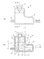
図2および図3に示すように、リザーブタンク20は、その上部(図2(b)中のS1の範囲;以下、単に上部S1ともいう)に冷却水Lを注入する注水口21a(注入口)が形成され、注入された冷却水Lをその上方の空気溜まりと共に貯留するタンク本体21と、注水口21aを加圧・密閉することができるようにタンク本体21の注水口21a付近に着脱可能に設けられた公知のタンクキャップ22とを有している。
As shown in FIGS. 2 and 3, the
タンク本体21の水平方向一端側(水平方向一方側)の下部(図2(b)中のS2の範囲;以下、単に下部S2ともいう)には、ラジエータ12のアッパータンク部12a(冷却水の戻り側)に配管接続された円筒状の第1連通管部23と、この第1連通管部23に対し所定距離を隔てて平行に離間し、エンジン11への冷却水供給側であるウォーターポンプ15の吸入側に配管接続された第2連通管部24(図3参照)とが、それぞれタンク本体21と一体に固定されており、第1連通管部23および第2連通管部24内の連通路23a、24aはタンク本体21の下部S2内、特にタンク本体21の内底面21bに近接する位置で開口した連通孔となっている。
An
また、タンク本体21は、その水平方向他端側(水平方向他方側;図2(a)中の右端側)の下部で水平方向一端側の下部S2から離隔する方向に膨出した膨出部25を有している。タンク本体21の内底面21bからこの膨出部25の上方側の内面25hまでの高さは、タンク本体21の内底面21bからの冷却水Lの注水時液面高さの許容範囲、すなわち図2(b)中のLOWレベルからFULLレベルまでの範囲より上方(許容液面レベルの最も高い位置であるFULLレベルより更に上方)に位置し、かつ、エンジン11の運転中にラジエータ12側からの冷却水Lの戻りによって上昇するときの液面レベルBよりはわずかに低くなるように設定されている。
Further, the
さらに、図2(a)に示すように、タンク本体21の上部S1の水平方向における内幅d2(最小内径)は、注水口21aの内径d1よりも大きくなっており、図2(b)に示すように、タンク本体21の下部S2の高さをタンク本体21の内底面21bから膨出部25の上方側の内面25hまでの高さとするとき、それを超えるタンク本体21の上部S1の容積がその水平断面積に相当する範囲外の膨出領域S3に膨出した膨出部25内の容積とほぼ等しいか、わずかに大きくなっている。
Further, as shown in FIG. 2 (a), the inner width d2 (minimum inner diameter) of the upper part S1 of the
また、タンク本体21内にはタンク本体21の内底面21bから上方に突出する隔壁部26が設けられており、タンク本体21内はこの隔壁部26によって、水平方向(左右)一方側に位置する一方側の貯留室27と、水平方向他方側に位置する他方側の貯留室28とに区画されている。隔壁部26は、さらに、一方側の貯留室27を一対の室27a、27b(図3参照)に区画するようタンク本体21内で水平方向一端側に向かって突出する突出壁部26pを有している。そして、タンク本体21の水平方向一端側の下部S2において、一方の室27aは第1連通管部23を通してラジエータ12のアッパータンク部12a側に連通し、他方の室27bはラジエータ12のロワタンク部12bからエンジン11側への冷却水供給通路14aに連通している。
Further, a
一方側の貯留室27の一対の室27a、27bはタンク本体21内で車両の前後方向に隣り合っており、隔壁部26には、図3および図4に示すように、タンク本体21内の下部S2側で一方側の貯留室27と他方側の貯留室28を互いに連通させ、他方側の貯留室28を介して一対の室27a、27bを互いに連通させるように、一対の室27a、27bをそれぞれ他方側の貯留室28に連通させる一対の下部連通孔26a、26bがそれぞれ形成されている。そして、他方側の貯留室28は、一方側の貯留室27の一対の室27a、27bおよび第1連通管部23および第2連通管部24内の連通路23a、24aを通してラジエータ12の冷却液の戻り側と供給側とに連通している。
The pair of
隔壁部26は、タンク本体21の内底面21bとの間に下部連通孔26a、26bに代わる連通孔を形成するものであってもよいし、下部連通孔26a、26bの形状は円形、楕円形、矩形、その他任意の形状であってよく、複数設けられてもよい。ただし、一対の室27a、27bに対応する一対の下部連通孔26a、26bは互いに離隔するようタンク本体21の両側壁面に近接しているのがよい。
The
さらに、隔壁部26には、タンク本体21の上部S1内で一方側の貯留室27と他方側の貯留室28を互いに連通させ、タンク本体21内の上部S1側で他方側の貯留室28を介して一対の室27a、27bを互いに連通させるように、一対の室27a、27bをそれぞれ他方側の貯留室28に連通させる一対の上部連通孔26j、26kが形成されており、一方側の貯留室27と他方側の貯留室28の上部側に同一圧力の空気溜まりが形成されるようになっている。
Further, the
なお、本実施形態では、注水口21a近傍の隔壁部26は、例えば図2(b)に示すように、注水口21aから注水された冷却水Lを他方側の貯留室28側に導入するように、注水口21aよりも同図の左側、すなわち水平方向一端側に位置するように配置されているが、注入された冷却水Lを一方側の貯留室27側のみにまたは両貯留室27、28に導入するような形状としてもよい。例えば、注水口21a内に一方側の貯留室27の一対の室27a、27bの上端がそれぞれ開口してもよいし、隔壁部26の注水口21a近傍を切り欠いて、空気流通用の上部連通孔26j、26kに代わる切欠穴を形成してもよい。
In the present embodiment, the
次に、その作用を説明する。 Next, the operation will be described.
上述のように構成された本実施形態のリザーブタンク20では、膨出部25によりタンク本体21の下部S2側に十分な冷却液貯留量が確保され、タンク本体21の上部S1では一方側の貯留室27側および他方側の貯留室28が空気流通用の上部連通孔26j、26kにより互いに連通することから、リザーブタンク20の全高を抑えても、一方側の貯留室27側および他方側の貯留室28の上部に一様な圧力の所要量の空気溜まりを形成することができ、エンジン11の運転時におけるラジエータ12側からの冷却水Lの戻りを確実に吸収することができる。
In the
また、エンジン11の運転時に水平方向他端側に向かう加速度、例えば横向き加速度が作用し、リザーブタンク20内に貯留された冷却水Lの液面Bが例えば図2(b)に一点鎖線で示すように水平方向一端側に傾斜しても、その液面B´はリザーブタンク20の下部S2側に比較して水平断面積の狭い上部S1内に制限される。しかも、隔壁部26がバッフルプレートとして機能し、比較的短時間の液面傾斜に対しては水平方向一方側の貯留室27の液高さB´sをより高く維持するのに寄与することになる。したがって、大きな横向き加速度が作用するコーナリング時のような走行状態が比較的長く続くような場合でも、ラジエータ12の冷却水Lの戻り側と供給側にそれぞれ配管接続された水平方向一端側の下部、すなわち、第1連通管部23および第2連通管部24の連通路23a、24a(連通孔の開口部分)が液面上に露出することはなく、それらの液中配置状態を確実に維持できることになる。
Further, when the
さらに、一方側の貯留室27が一対の室27a、27bに区画・分割され、これら一対の室27a、27bを他方側の貯留室28に連通させる下部連通孔26a、26bが隔壁部26に形成されていることから、一方側の貯留室27の片方の室27aに入るラジエータ12側からの気泡含有の冷却水Lがもう片方の室27bにそのまま入ってエンジン側に供給されてしまうといったことがなく、片方の室27aから他方側の貯留室28に入って気泡が空気溜まりに抜けた後の冷却水Lがエンジン側に供給されることになる。したがって、リザーブタンク20からエンジン11側に供給される冷却水Lへの気泡の混入によってウォーターポンプ15内でキャビテーションが発生したり、そのためにエンジン11の冷却性能が低下したりするというようなことが防止され、タンク高さを抑えても、大きな加速度が作用するような走行状態下でエンジン11側への冷却水L中に空気が混入するのを確実に防止することができる。
Further, the
また、タンク本体21の水平方向一端側の下部S2でラジエータ12側およびエンジン11側への配管接続がなされ、冷却水Lの液面Bも低く抑えられることから、ラジエータ12の内圧上昇をも抑えることができ、タンク本体21を肉厚にせずに済む。
In addition, piping connection to the
加えて、タンク本体21の上部S1の内幅d2が注水口21aの内径以上に大きくなっているので、注水作業性が良好となる。
In addition, since the inner width d2 of the upper portion S1 of the
このように、本実施形態においては、膨出部25によりタンクの下部S2に十分な冷却液貯留量を確保することで、タンク高さを抑えても、一方側および他方側の貯留室27、28に一様な圧力の空気溜まりを形成することができ、かつ、タンク本体21の上部S1内に所要量の空気溜りを形成することができ、エンジン11の運転時におけるラジエータ12側からの冷却水Lの戻りを確実に吸収させることができる。
Thus, in the present embodiment, by securing a sufficient amount of coolant storage in the lower portion S2 of the tank by the bulging
また、運転時にリザーブタンク20内の冷却液面が傾斜しても、その液面はタンク本体21の下部に比較して水平断面積の狭い上部S1内に制限され、更に隔壁部26のバッフルプレート機能も加わることから、水平方向一端側の下部の第1連通管部23および第2連通管部24の連通路23a、24aの液中配置状態を確実に維持することができる。本実施形態では、リザーブタンク20はその水平方向両端側を車両の左右方向に向けて車両に搭載されるので、例えばサーキット走行時のように横向き加速度により液面傾斜が顕著になるような場合にも十分に対応できる。
Further, even if the coolant level in the
さらに、タンク本体21の水平方向一端側の下部S2でラジエータ12側およびエンジン11側への配管接続がなされ、液面Bも低く抑えられることから、ラジエータ12の内圧上昇を抑えることができ、低コストのリザーブタンクを提供することができる。
Further, since the pipe connection to the
なお、上述の実施の形態では、第1連通管部23および第2連通管部24をタンク本体21の水平方向一端側の下部S2に平行に配置し、かつ、タンク本体21と一体にしていたが、その配管経路は平行でなくてもよいし、上下方向に湾曲していてもよい。
In the above-described embodiment, the first
また、第1連通管部23および第2連通管部24のうちいずれか一方、例えば第2連通管部24を他方側の貯留室28の底部側に直接開口させることもでき、そのようにすれば、突出壁部26pは必要ではなく、一方側の貯留室27を一対の室27a、27bに区画・分割する必要はない。
In addition, one of the first
以上説明したように、本発明は、膨出部によりタンク下部に十分な冷却液貯留量を確保することで、タンク高さを抑えても所要の空気溜りを形成してエンジンの運転時におけるラジエータ側からの冷却液の戻りを確実に吸収させることができ、しかも、リザーブタンク内の冷却液面が傾斜したとしても、その液面をリザーブタンクの下部に比較して水平断面積の狭い上部内に制限し、かつ、隔壁部にバッフルプレート機能を持たせることで、ラジエータ側に配管接続された水平方向一端側の下部を液面上に露出させることなくその液中配置状態を確実に維持させることができ、さらに、水平方向一端側の下部でラジエータ側への配管接続をなして液面を低く抑え、ラジエータの内圧上昇をも抑えることができるので、タンク高さを抑えても大きな加速度が作用するような走行状態下でエンジン側への冷却液中に空気が混入するのを確実に防止することができる低コストのリザーブタンクを提供することができるという効果を奏するものであり、リザーブタンクおよび同タンクを備えたエンジン冷却装置、特に冷却液の上方に冷却液面変化に応じて体積変化する空気溜まりを形成するようにした密閉型のリザーブタンクおよびエンジン冷却装置全般に有用である。 As described above, the present invention ensures a sufficient amount of coolant stored in the lower portion of the tank by the bulging portion, thereby forming a required air reservoir even when the tank height is suppressed, thereby providing a radiator during engine operation. Even if the coolant level in the reserve tank is inclined, the liquid level can be absorbed in the upper part where the horizontal cross-sectional area is narrow compared to the lower part of the reserve tank. In addition, the baffle plate function is provided in the partition wall, so that the lower part of the horizontal one end connected to the radiator side is securely maintained without exposing the lower part on the liquid level. In addition, it is possible to keep the liquid level low by connecting the pipe to the radiator side at the lower part on one end side in the horizontal direction, and to suppress the rise in the internal pressure of the radiator. It is possible to provide a low-cost reserve tank that can reliably prevent air from being mixed into the coolant to the engine side under traveling conditions in which a large acceleration acts. This is useful for a reserve tank and an engine cooling device equipped with the tank, and particularly for a closed type reserve tank and an engine cooling device in general that form an air reservoir whose volume changes in accordance with the change of the coolant level above the coolant. is there.
1 エンジン冷却装置
11 エンジン
11a 冷却水入口
11b 冷却水出口
11w 冷却通路
12 ラジエータ
12a アッパータンク部
12b ロワタンク部
13 アッパーホース
14 ロワホース
15 ウォーターポンプ
16 サーモスタット
17 加圧・密閉式ラジエータキャップ
18a、18b 配管
19 車室側ヒーター
20 リザーブタンク
21 タンク本体
21a 注水口(注入口)
21b 内底面
22 タンクキャップ
23 第1連通管部
23a、24a 連通路(連通孔)
24 第2連通管部
25 膨出部
25h 内面
26 隔壁部
26a、26b 下部連通孔
26j、26k 上部連通孔
26p 突出壁部
27 一方側の貯留室
27a、27b 一対の室
28 他方側の貯留室
d1 注水口の内径
d2 タンク本体の上部の内幅
L 冷却水(冷却液)
S1 タンク本体の上部
S2 タンク本体の下部
S3 膨出領域
DESCRIPTION OF
21b
24 Second
S1 Upper part of tank body S2 Lower part of tank body S3 Swelling area
Claims (8)
前記タンク本体が、前記タンク本体の水平方向他方側の下部で前記水平方向一方側の下部から離隔する方向に膨出した膨出部と、前記タンク本体の内底面から上方に突出するとともに前記タンク本体内を前記水平方向一方側に位置する一方側の貯留室と前記水平方向他方側に位置する他方側の貯留室とに区画する隔壁部とを有し、
前記隔壁部が、前記タンク本体内の下部側で前記一方側の貯留室と前記他方側の貯留室とを連通させる下部連通孔と、前記タンク本体の上部内で前記一方側の貯留室と前記他方側の貯留室とを連通させる上部連通孔とを形成しているとともに、
前記タンク本体の下部で前記一方側の貯留室が、前記ラジエータの冷却液の戻り側と供給側に対応する一対の室に区画されるとともに、該一対の室が前記ラジエータの冷却液の戻り側と供給側に連通するよう、前記タンク本体の下部に前記一対の室に対応する一対の連通孔が形成されていることを特徴とするリザーブタンク。 A pipe is connected to the radiator side at the lower part on one side in the horizontal direction, and an inlet for injecting cooling liquid is formed at the upper part. The tank main body for storing the cooling liquid together with an air reservoir thereabove and the inlet are sealed. A sealed reserve tank with a cap,
The tank body protrudes upward from an inner bottom surface of the tank body, and protrudes upward from an inner bottom surface of the tank body, at a lower portion on the other side in the horizontal direction of the tank body, and in a direction away from the lower portion on the one side in the horizontal direction. A partition that divides the main body into a storage chamber on one side positioned on one side in the horizontal direction and a storage chamber on the other side positioned on the other side in the horizontal direction;
The partition wall includes a lower communication hole that communicates the storage chamber on the one side and the storage chamber on the other side on the lower side in the tank body, the storage chamber on the one side in the upper part of the tank body, and the While forming an upper communication hole for communicating with the other storage chamber,
The storage chamber on the one side at the bottom of the tank body is partitioned into a pair of chambers corresponding to the return side and the supply side of the coolant of the radiator , and the pair of chambers is the return side of the coolant of the radiator A reserve tank, wherein a pair of communication holes corresponding to the pair of chambers are formed in a lower portion of the tank body so as to communicate with the supply side.
前記ラジエータと、
前記冷却液をエンジン内および前記ラジエータ内を通して循環させるウォーターポンプと、を備えたエンジン冷却装置。 The reserve tank according to any one of claims 1 to 6,
The radiator;
An engine cooling device comprising: a water pump for circulating the coolant through the engine and the radiator.
Priority Applications (1)
| Application Number | Priority Date | Filing Date | Title |
|---|---|---|---|
| JP2007026552A JP4890286B2 (en) | 2007-02-06 | 2007-02-06 | Reserve tank and engine cooling device equipped with the same |
Applications Claiming Priority (1)
| Application Number | Priority Date | Filing Date | Title |
|---|---|---|---|
| JP2007026552A JP4890286B2 (en) | 2007-02-06 | 2007-02-06 | Reserve tank and engine cooling device equipped with the same |
Publications (2)
| Publication Number | Publication Date |
|---|---|
| JP2008190442A JP2008190442A (en) | 2008-08-21 |
| JP4890286B2 true JP4890286B2 (en) | 2012-03-07 |
Family
ID=39750761
Family Applications (1)
| Application Number | Title | Priority Date | Filing Date |
|---|---|---|---|
| JP2007026552A Expired - Fee Related JP4890286B2 (en) | 2007-02-06 | 2007-02-06 | Reserve tank and engine cooling device equipped with the same |
Country Status (1)
| Country | Link |
|---|---|
| JP (1) | JP4890286B2 (en) |
Families Citing this family (4)
| Publication number | Priority date | Publication date | Assignee | Title |
|---|---|---|---|---|
| JP2014070490A (en) * | 2012-09-27 | 2014-04-21 | Toyoda Gosei Co Ltd | Reserve tank |
| EP3850199B1 (en) * | 2018-09-11 | 2022-11-02 | Wärtsilä Finland Oy | A compartmentalized header tank for liquid coolant, a multi-engine header tank arrangement, and a power plant and a marine vessel equipped with such multi-engine header tank arrangement |
| JP7043537B2 (en) * | 2020-03-30 | 2022-03-29 | 本田技研工業株式会社 | Expansion tank |
| CN111591127B (en) * | 2020-05-31 | 2022-08-09 | 重庆长安汽车股份有限公司 | Automobile water storage bottle |
Family Cites Families (3)
| Publication number | Priority date | Publication date | Assignee | Title |
|---|---|---|---|---|
| JPH0466321A (en) * | 1990-07-06 | 1992-03-02 | Zexel Corp | Air conditioner for vehicle |
| JPH05209522A (en) * | 1992-01-31 | 1993-08-20 | Nippondenso Co Ltd | Completely closed reserve tank |
| JP4066930B2 (en) * | 2003-10-16 | 2008-03-26 | 株式会社デンソー | Gas-liquid separation structure of reserve tank |
-
2007
- 2007-02-06 JP JP2007026552A patent/JP4890286B2/en not_active Expired - Fee Related
Also Published As
| Publication number | Publication date |
|---|---|
| JP2008190442A (en) | 2008-08-21 |
Similar Documents
| Publication | Publication Date | Title |
|---|---|---|
| JP6461364B2 (en) | Expansion tank | |
| JP4600537B2 (en) | Reserve tank | |
| JP4825700B2 (en) | Reserve tank and engine cooling device equipped with the same | |
| JP4890286B2 (en) | Reserve tank and engine cooling device equipped with the same | |
| BR112012022051B1 (en) | auxiliary water tank for an engine cooling system and engine cooling system | |
| JP6003243B2 (en) | Reserve tank | |
| JP2007009752A (en) | Reserve tank | |
| JP2020023965A (en) | Cooling system of vehicle | |
| JP2024503731A (en) | Expansion tanks, cooling systems, and automobiles | |
| JP4826574B2 (en) | Reserve tank | |
| JP2006329052A (en) | Reserve tank used for engine cooling system | |
| JP2017101573A (en) | Cooling liquid tank | |
| JP6730766B2 (en) | Arrangement structure of cooling system in construction machinery | |
| JP2003065696A (en) | Radiator | |
| JP6222460B2 (en) | Engine cooling circuit | |
| JP4591213B2 (en) | Piping with refrigerant inlet | |
| GB2452070A (en) | Cooling System Expansion Tank | |
| JP2012092762A (en) | Reserve tank | |
| JP5782702B2 (en) | Engine cooling system | |
| JP2008274783A (en) | Cooling system of internal combustion engine | |
| KR20220050595A (en) | Reservoir tank | |
| JP7306288B2 (en) | Reserve tank | |
| CN219583942U (en) | Kettle and vehicle cooling system | |
| JP2015229144A (en) | Gas-liquid separator | |
| CN205387970U (en) | A add water stand subassembly and operation machinery for operation machine cooling package |
Legal Events
| Date | Code | Title | Description |
|---|---|---|---|
| A621 | Written request for application examination |
Free format text: JAPANESE INTERMEDIATE CODE: A621 Effective date: 20090720 |
|
| A977 | Report on retrieval |
Free format text: JAPANESE INTERMEDIATE CODE: A971007 Effective date: 20101224 |
|
| A131 | Notification of reasons for refusal |
Free format text: JAPANESE INTERMEDIATE CODE: A131 Effective date: 20110104 |
|
| A521 | Written amendment |
Free format text: JAPANESE INTERMEDIATE CODE: A523 Effective date: 20110304 |
|
| A711 | Notification of change in applicant |
Free format text: JAPANESE INTERMEDIATE CODE: A711 Effective date: 20110304 |
|
| A521 | Written amendment |
Free format text: JAPANESE INTERMEDIATE CODE: A821 Effective date: 20110304 |
|
| A521 | Written amendment |
Free format text: JAPANESE INTERMEDIATE CODE: A523 Effective date: 20110428 |
|
| A131 | Notification of reasons for refusal |
Free format text: JAPANESE INTERMEDIATE CODE: A131 Effective date: 20110906 |
|
| A521 | Written amendment |
Free format text: JAPANESE INTERMEDIATE CODE: A523 Effective date: 20111019 |
|
| TRDD | Decision of grant or rejection written | ||
| A01 | Written decision to grant a patent or to grant a registration (utility model) |
Free format text: JAPANESE INTERMEDIATE CODE: A01 Effective date: 20111206 |
|
| A01 | Written decision to grant a patent or to grant a registration (utility model) |
Free format text: JAPANESE INTERMEDIATE CODE: A01 |
|
| A61 | First payment of annual fees (during grant procedure) |
Free format text: JAPANESE INTERMEDIATE CODE: A61 Effective date: 20111214 |
|
| FPAY | Renewal fee payment (event date is renewal date of database) |
Free format text: PAYMENT UNTIL: 20141222 Year of fee payment: 3 |
|
| R250 | Receipt of annual fees |
Free format text: JAPANESE INTERMEDIATE CODE: R250 |
|
| R250 | Receipt of annual fees |
Free format text: JAPANESE INTERMEDIATE CODE: R250 |
|
| R250 | Receipt of annual fees |
Free format text: JAPANESE INTERMEDIATE CODE: R250 |
|
| LAPS | Cancellation because of no payment of annual fees |