JP2017185905A - Traverser for railway vehicle - Google Patents
Traverser for railway vehicle Download PDFInfo
- Publication number
- JP2017185905A JP2017185905A JP2016076424A JP2016076424A JP2017185905A JP 2017185905 A JP2017185905 A JP 2017185905A JP 2016076424 A JP2016076424 A JP 2016076424A JP 2016076424 A JP2016076424 A JP 2016076424A JP 2017185905 A JP2017185905 A JP 2017185905A
- Authority
- JP
- Japan
- Prior art keywords
- rail
- tongrel
- traverser
- railway vehicle
- base
- Prior art date
- Legal status (The legal status is an assumption and is not a legal conclusion. Google has not performed a legal analysis and makes no representation as to the accuracy of the status listed.)
- Pending
Links
Images


Abstract
Description
本発明は、例えば、鉄道車両の検査、修繕等を行うために、施設内の引き込みレール上を走行させる仮台車を搬送する鉄道車両用トラバーサに関する。 The present invention relates to a traverser for a railway vehicle that transports a temporary carriage that runs on a pull-in rail in a facility, for example, in order to inspect and repair the railway vehicle.
一般に、鉄道車両の分解検査、修繕等を行うためには、鉄道車両における車体と台車とを分離する必要があり、鉄道車両の入場時に、本線レール上を走行する本台車から、施設内に敷設した引き込みレール上を走行する仮台車に交換する作業が行われている。そして、分解検査、修繕終了後に鉄道車両に履かせた仮台車を本台車に交換する作業が行われている。この場合、本台車と仮台車とを交換し終え、不要となった仮台車を返送ラインへ移送する手段として鉄道車両用トラバーサを使用する。図9に示すように、鉄道車両用トラバーサ100を、鉄道車両の作業場に向けて移動レールR2上を移動させ、該当するレールR1上に待機する鉄道車両101と対面する位置で停止させた上で、鉄道車両用トラバーサ100の側端部に装着したトングレール103の先端部を当該レールR1の上面に当接させる。そして、当該レールR1上に待機する鉄道車両101の仮台車102b、103bがトングレール103を経由して鉄道車両用トラバーサ100の床面レール104上へ移動可能な状態にする。
上記トングレール103は、図10に示すように、一般に、トラバーサの側端部に跳ね上げ回動可能に装着され、その先端が先細り状に形成されている(特許文献1を参照)。
Generally, in order to perform overhaul inspection, repair, etc. of a railway vehicle, it is necessary to separate the car body and the bogie from the railway car. When the railway car enters, it is installed in the facility from the main car that runs on the main rail. The work of exchanging with a temporary carriage that runs on the pull-in rail is performed. Then, after completion of the overhaul and repair, an operation of replacing the temporary carriage worn on the railway vehicle with the main carriage is performed. In this case, the railcar traverser is used as a means for transferring the temporary carriage that has become unnecessary after the exchange between the main carriage and the temporary carriage to the return line. As shown in FIG. 9, the
As shown in FIG. 10, the
しかしながら、上記トングレール103では、図10に示すように、鉄道車両用トラバーサ100の床面レール104と鉄道車両101が待機するレールR1との上下段差に対するレール面103Sの勾配を緩やかにしてワークの移動を容易にする必要があり、その全長Lが長くならざるを得ない。例えば、ワークである本台車又は仮台車の手動等による移動を容易にするためには、レール面103Sの傾斜角θが6〜7°程度以内とする必要があり、その場合、トングレール103の全長Lが2.0〜2.5m程度以上となる。そのため、トングレール103を跳ね上げ状態(格納状態)から倒伏状態(使用状態)に回動させるとき、レールR1上に待機する鉄道車両101の先端部とトングレール103の先端部とを干渉させないためには、レールR1上に待機する鉄道車両101を鉄道車両用トラバーサ100からトングレール103の上記全長L以上に離間させなければならなかった。したがって、跳ね上げ式のトングレール103においては、トングレール103の全長Lに起因して車両待機スペースを増大せざるを得ないという問題があった。特に、新幹線先頭車両のように、車両先端部の突出量が大きい車両の場合には、既存の車両待機スペース内で、トングレール103を車両先端部と干渉することなく上下回動させることが困難であった。
However, in the above-described Tongleil 103, as shown in FIG. 10, the slope of the
本発明は、かかる問題を解決するためになされたものであり、車両待機スペースの省スペース化に寄与でき、レール上に待機する鉄道車両の先端部とトングレールの先端部とが干渉することなくコンパクトに、トングレールを格納状態から使用状態に移動させ得る鉄道車両用トラバーサを提供することを目的とする。 The present invention has been made to solve such a problem, can contribute to space saving of the vehicle standby space, and the front end portion of the railway vehicle waiting on the rail does not interfere with the front end portion of the Tongle rail. An object of the present invention is to provide a railway vehicle traverser that can move a tongrel from a retracted state to a used state in a compact manner.
上記目的を達成するため、本発明に係る鉄道車両用トラバーサは、以下の構成を備えている。
(1)ワークを搭載し移動レール上を走行可能に形成された基台と、当該基台の側端部に格納可能に装着されたトングレールとを備え、前記移動レールと直交する方向に敷設され鉄道車両が待機するレール上の前記ワークを前記トングレールを経由して前記基台上に搭載し、移送する鉄道車両用トラバーサであって、
前記トングレールは、先端部が略水平方向に回動可能に形成され、かつ、前記先端部は、使用時において前記レールの上端と当接し、上下方向で先細り状に形成されていることを特徴とする。
In order to achieve the above object, a railcar traverser according to the present invention comprises the following arrangement.
(1) A pedestal mounted with a workpiece and configured to be able to run on a moving rail, and a tongrel mounted on a side end of the pedestal so as to be retractable, and laid in a direction orthogonal to the moving rail. A railcar traverser for mounting and transferring the work on the rail on which the railcar is waiting on the base via the Tongrel.
The Tongleil has a tip portion formed so as to be rotatable in a substantially horizontal direction, and the tip portion is in contact with the upper end of the rail in use and is formed in a tapered shape in the vertical direction. And
本発明においては、トングレールは、先端部が略水平方向に回動可能に形成されているので、トングレールの先端部における上下方向の高さを略一定に維持しつつ、トングレールの先端部を回動させることができる。そのため、鉄道車両が鉄道車両用トラバーサと近接する位置で待機していても、トングレールの先端部が待機する鉄道車両の先端部と干渉するのを回避しながら、トングレールを格納状態から使用状態に移動させることができる。
また、トングレールの先端部は、使用時において鉄道車両が待機するレールの上端と当接し、上下方向で先細り状に形成されているので、トングレールを格納状態から使用状態に移動させるとき、レール上に待機する鉄道車両における先端部の下端と当該レールの上端との間に形成される隙間をトングレールの先端部が通過することができる。そのため、トングレールの全長を長くでき、トングレールのレール面の勾配を緩やかにしてワークの移動を容易にすることができる。
その結果、狭い車両待機スペース内で、鉄道車両が鉄道車両用トラバーサと近接する位置で待機していても、鉄道車両の先端部とトングレールの先端部とが干渉することなくすれ違い、トングレールを格納状態から使用状態に移動させ、鉄道車両が待機するレール上のワークをトングレールを経由して基台上に無理なく搭載し、移送することができる。
よって、本発明によれば、車両待機スペースの省スペース化に寄与でき、レール上に待機する鉄道車両の先端部とトングレールの先端部とが干渉することなくすれ違い、トングレールを格納状態から使用状態に移動させ得る鉄道車両用トラバーサを提供することができる。
In the present invention, since the tongrel is formed so that the tip portion thereof is rotatable in a substantially horizontal direction, the tip portion of the tongrel is maintained at a substantially constant height in the vertical direction at the tip portion of the tongrel. Can be rotated. Therefore, even if the railway vehicle is waiting at a position close to the railcar traverser, the Tongleil can be used from the retracted state while avoiding the interference with the leading end of the waiting railway vehicle. Can be moved to.
In addition, the tip of the Tongrel is in contact with the upper end of the rail where the railway vehicle waits during use and is tapered in the vertical direction. The front end of the Tongleil can pass through a gap formed between the lower end of the front end of the railway vehicle waiting on the top and the upper end of the rail. For this reason, the overall length of the Tongrel can be increased, and the slope of the rail surface of the Tongrel can be made gentle to facilitate the movement of the workpiece.
As a result, even if the railway vehicle is waiting at a position close to the railcar traverser in a narrow vehicle waiting space, the leading edge of the railway vehicle and the leading edge of the tongrail are not interfered with each other. It is possible to move from the retracted state to the in-use state so that the work on the rails on which the railway vehicle stands by can be mounted and transported on the base via the Tongrel.
Therefore, according to the present invention, it is possible to contribute to space saving of the vehicle standby space, the front end portion of the railway vehicle waiting on the rail and the front end portion of the tongrel pass each other, and the tongler is used from the retracted state. It is possible to provide a railcar traverser that can be moved to a state.
(2)(1)に記載された鉄道車両用トラバーサにおいて、
前記トングレールは、前記基台の側端部に連結される基端部から長手方向の中間部まで前記レールと平行に形成され、かつ、前記中間部を中心にして前記先端部が当該レールに対して平行な状態から直交する状態まで略90°回動可能に形成されていることを特徴とする。
(2) In the railcar traverser described in (1),
The tongrel is formed in parallel with the rail from a base end portion connected to a side end portion of the base to a middle portion in a longitudinal direction, and the tip portion is centered on the middle portion. It is characterized in that it is formed so as to be able to rotate approximately 90 ° from a parallel state to an orthogonal state.
本発明においては、トングレールは、基台の側端部に連結される基端部から長手方向の中間部まで鉄道車両が待機するレールと平行に形成され、かつ、中間部を中心にして先端部が当該レールに対して平行な状態から直交する状態まで略90°回動可能に形成されているので、略90°回動する先端部側トングレールの重量を軽量化して、基台の側端部に連結される基端部側トングレールの支持構造や先端部の回動機構等をより一層簡素化させることができる。なお、トングレールの格納状態において、トングレールの中間部又は先端部とレール上に待機する鉄道車両の先端部との最小隙間は、100〜150mm程度確保されていることが好ましい。 In the present invention, the tongrel is formed in parallel with the rail on which the railway vehicle waits from the base end connected to the side end of the base to the intermediate portion in the longitudinal direction, and the tip is centered on the intermediate portion. Since the portion is formed so as to be able to turn approximately 90 ° from a state parallel to the rail to a state orthogonal to the rail, the weight of the tip side Tongler turning about 90 ° is reduced, and the base side It is possible to further simplify the support structure of the proximal end side Tongler connected to the end portion, the rotation mechanism of the distal end portion, and the like. It should be noted that it is preferable that the minimum clearance between the intermediate portion or the front end portion of the Tongrel and the front end portion of the railway vehicle standing on the rail is secured in the range of 100 to 150 mm when the Tongrel is stored.
(3)(1)又は(2)に記載された鉄道車両用トラバーサにおいて、
前記トングレールは、前記基台の側端部に対して上方へ付勢された状態で前記基台に支持され、無負荷時において前記トングレールの下端と前記レールの上端との間に所定の隙間が形成されていることを特徴とする。
(3) In the railcar traverser described in (1) or (2),
The tongrel is supported by the base in a state of being urged upward with respect to the side end of the base, and a predetermined distance is provided between the lower end of the tongrel and the upper end of the rail when no load is applied. A gap is formed.
本発明においては、トングレールは、基台の側端部に対して上方へ付勢された状態で基台に支持され、無負荷時においてトングレールの下端と鉄道車両が待機するレールの上端との間に所定の隙間が形成されているので、本鉄道車両用トラバーサが移動レール上を移動するときにトングレールが上下方向に多少振動しても、トングレールの下端が、鉄道車両が待機するレールの上端と干渉することを防止できる。なお、トングレールを上方へ付勢する手段は、ばね等の弾性体やシリンダ等の空圧機器又は油圧機器等が該当し、特に限定されることはない。また、無負荷時においてトングレールの下端と鉄道車両が待機するレールの上端との間に形成される所定の隙間は、20〜30mm程度が好ましい。所定の隙間が20〜30mm程度あれば、トングレールを格納状態から使用状態に移動させるとき、トングレールの上端とレール上に待機する鉄道車両の下端とが干渉することを簡単に回避させることができるからである。 In the present invention, the tongrel is supported by the base in a state of being biased upward with respect to the side end of the base, and the lower end of the tongrel and the upper end of the rail on which the railway vehicle stands by when no load is applied. Since a predetermined gap is formed between the railcar, even if the tongrel vibrates somewhat in the vertical direction when the traverser for the railcar moves on the moving rail, the railcar waits at the lower end of the tongrail. Interference with the upper end of the rail can be prevented. The means for urging the Tongrel upward is applicable to an elastic body such as a spring, a pneumatic device such as a cylinder, or a hydraulic device, and is not particularly limited. Further, it is preferable that the predetermined gap formed between the lower end of the Tongleil and the upper end of the rail on which the railway vehicle stands by at no load is about 20 to 30 mm. If the predetermined gap is about 20 to 30 mm, it is possible to easily avoid the interference between the upper end of the Tongler and the lower end of the railcar waiting on the rail when the Tongrel is moved from the stored state to the used state. Because it can.
本発明によれば、車両待機スペースの省スペース化に寄与でき、レール上に待機する鉄道車両の先端部とトングレールの先端部とが干渉することなくすれ違い、トングレールを格納状態から使用状態に移動させ得る鉄道車両用トラバーサを提供することができる。 According to the present invention, it is possible to contribute to space saving of the vehicle standby space, and the front end portion of the railway vehicle waiting on the rail and the front end portion of the Tongle rail pass without interfering, and the Tongle rail is changed from the stored state to the used state. A traverser for a railway vehicle that can be moved can be provided.
次に、本発明の実施形態に係る鉄道車両用トラバーサについて、図面を参照しながら詳細に説明する。はじめに、本実施形態に係る鉄道車両用トラバーサの全体構成を説明し、その後、トングレールの詳細構造を説明し、更に本鉄道車両用トラバーサの動作方法について説明する。 Next, a railcar traverser according to an embodiment of the present invention will be described in detail with reference to the drawings. First, the overall configuration of the railcar traverser according to the present embodiment will be described, then the detailed structure of the tongrel will be described, and further the operation method of the railcar traverser will be described.
<鉄道車両用トラバーサの全体構成>
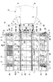
まず、本実施形態に係る鉄道車両用トラバーサの全体構成について、図1〜図3を用いて説明する。図1に、本発明の実施形態に係る鉄道車両用トラバーサの平面図を示す。図2に、図1に示す鉄道車両用トラバーサの側面図を示す。図3に、図1に示すA−A断面図を示す。
<Overall configuration of railcar traverser>
First, the overall configuration of the railcar traverser according to the present embodiment will be described with reference to FIGS. FIG. 1 is a plan view of a railcar traverser according to an embodiment of the present invention. FIG. 2 shows a side view of the railcar traverser shown in FIG. FIG. 3 is a cross-sectional view taken along line AA shown in FIG.
図1〜図3に示すように、本実施形態に係る鉄道車両用トラバーサ10は、ワークである、例えば、仮台車1(1a、1b)を搭載し移動レール2上を走行可能に形成された基台3と、当該基台3の側端部331に格納可能に装着されたトングレール4とを備え、移動レール2と直交する方向に敷設され鉄道車両5が待機するレール6上のワーク(仮台車1(1a、1b))をトングレール4を経由して基台3上に搭載し、移送する鉄道車両用トラバーサである。鉄道車両用トラバーサ10には、仮台車1(1a、1b)の他に、例えば、本台車を搭載することもできる。
As shown in FIGS. 1 to 3, the
仮台車1(1a、1b)は、鉄道車両5の分解検査、修繕等を行うため、施設内に敷設した引き込みレール上を走行可能に形成された台車である。仮台車1(1a、1b)は、駆動モータ12と連結された自走可能な車輪11と従走する車輪11とを備える自走用仮台車1aと、従走する車輪11のみを備える従走用仮台車1bと、から構成されている。仮台車1(1a、1b)は、自走用仮台車1aと従走用仮台車1bとが前後に連結された状態で基台3に搭載されている。
The temporary carriage 1 (1a, 1b) is a carriage formed so as to be able to travel on a pull-in rail laid in the facility in order to perform an overhaul inspection, repair, etc. of the
基台3は、略矩形状に形成された枠体に床板が接合された台車本体であって、走行方向(矢印Tの方向)に対して前後に位置する前端部31及び後端部32が高床状に形成され、前端部31と後端部32との間に挟まれた中央部33が低床状に形成されている。高床状に形成された前端部31及び後端部32の両側部には、移動レール2上を走行する走行車輪34が配置されている。後端部32の両側部に配置された走行車輪34には、駆動モータ35がそれぞれ連結されている。なお、基台3の前端部31には、駆動モータ35に電力を供給するバッテリ311が搭載され、基台3の後端部32には、油圧ユニット321及び操作盤322等が搭載されている。
The
基台3の中央部33には、仮台車1(1a、1b)を案内する床レール332が、床面と略同一の高さで本鉄道車両用トラバーサ10の走行方向と直交する方向に敷設されている。床レール332の軌間は、鉄道車両5が待機するレール6の軌間と同一である。床レール332は、基台3の中央部33の側端部331まで直線状に敷設されている。
In the
基台3の側端部331には、床レール332と同一の軌間で形成されたトングレール4が装着されている。トングレール4は、先端部43が略水平方向に回動可能に形成され、かつ、先端部43は、使用時において鉄道車両5が待機するレール6の上端と当接し、上下方向で先細り状に形成されている。
On the
<トングレールの詳細構造>
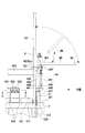
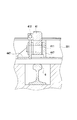
次に、本鉄道車両用トラバーサ10のトングレール4の詳細構造について、図4〜図7を用いて説明する。図4に、図1に示すトングレールの部分拡大平面図を示す。図5に、図4に示すB視側面図を示す。図6に、図4に示すC−C断面図を示す。図7に、図5に示すD−D断面図を示す。
<Detailed structure of Tongleil>
Next, the detailed structure of the
図4〜図7に示すように、トングレール4は、基台3の側端部331に連結される基端部41から長手方向で2分割される中間部42(42a)まで鉄道車両5が待機するレール6と平行に形成され、かつ、中間部42(42a)を中心にして先端部43が当該レール6に対して平行な状態(使用状態)から直交する状態(格納状態)まで略90°回動可能に形成されている。先端部43は、レールの左右外方へ観音開き状に回動する。また、トングレール4は、基台3の側端部331に対して上方へ付勢された状態で基台3に支持され、無負荷時においてトングレール4の下端4B2とレール6の上端61との間に所定の隙間dが形成されている。
As shown in FIG. 4 to FIG. 7, the
具体的には、トングレール4は、中間部42(42a、42b)にて基端部側トングレール4Aと先端部側トングレール4Bとに長手方向で2分割されている。基端部側トングレール4Aと先端部側トングレール4Bとが、中間部42(42a、42b)で当接すると、鉄道車両5が待機するレール6と一直線上に延設される。この場合、基端部側トングレール4Aの上端(レール面)4A1と先端部側トングレール4Bの上端(レール面)4B1とが緩やかな同一勾配(傾斜角:6°程度)の傾斜面を形成する。
Specifically, the
また、トングレール4の中間部42(42a、42b)には、基端部側トングレール4Aと先端部側トングレール4Bとが、中間部42(42a、42b)で当接する当接面の面積を増加させる当接ブロック421、421が付設されている。なお、基端部側トングレール4Aと先端部側トングレール4Bとが、中間部42(42a、42b)で当接したとき、当接ブロック421、421同士をピンで連結してもよい。これによって、トングレール4の使用時における屈曲等を防止することができる。また、後述するように、先端部側トングレール4Bを回動させる油圧シリンダ441のロッド部が伸縮するとき、その伸縮端を検知してトングレール4の使用時における屈曲を制御する方法でもよい。
Further, in the intermediate portion 42 (42a, 42b) of the
また、基端部側トングレール4Aの下端4A2は、上端(レール面)4A1と平行に形成されている。先端部側トングレール4Bの下端4B2は、略水平状に形成され、鉄道車両5が待機するレール6と一直線上に延設された状態で無負荷時(図5に仮想線で示す)においては、後述するばね部材448、455の付勢力によって鉄道車両5が待機するレール6の上端(レール面)61との間に所定の隙間dが形成されている。所定の隙間dは、20〜30mm程度であることが好ましい。所定の隙間dを調節するため、基端部側トングレール4Aの基端部41端面と当接する調整ボルト412が、基台3の側端部331に螺着されている。なお、先端部側トングレール4Bの下端4B2は、鉄道車両5が待機するレール6と一直線上に延設された状態で仮台車1(1a、1b)を移送する負荷時(図5に実線で示す)においては、ばね部材448、455が撓み、レール6の上端(レール面)61と当接する。
Moreover, the lower end 4A2 of the base end
また、基端部側トングレール4Aの中間部42aには、レールの左右外方へ突出する軸受ブラケット444が形成され、先端部側トングレール4Bの中間部42bには、回動したとき後方へ突出するリンクアーム442が形成されている。軸受ブラケッ444には、リンクアーム442がヒンジ軸443を介して水平方向へ回動自在に連結されている。リンクアーム442の後端部には、油圧シリンダ441のロッド部が連結されている。油圧シリンダ441及びリンクアーム442等によって、先端部側トングレール4Bの回動機構44を構成している。
Further, a
また、基端部側トングレール4Aの長手方向中央付近には、レールの左右外方に突出するシリンダ支持部材446が形成されている。シリンダ支持部材446には、油圧シリンダ441のケース後端部がヒンジ軸445を介して水平方向へ回動自在に連結されている。先端部側トングレール4Bの先端部43は、油圧シリンダ441のロッド部が伸縮することによって、ヒンジ軸443を中心に鉄道車両5が待機するレール6に対して平行な状態から直交する状態まで略水平方向へ略90°回動する。ここで、先端部側トングレール4Bの先端部43が鉄道車両5が待機するレール6に対して平行な状態は、トングレール4の使用状態に相当し、先端部側トングレール4Bの先端部43が鉄道車両5が待機するレール6に対して直交する状態は、トングレール4の格納状態に相当する。なお、トングレール4の格納状態において、中間部42又は先端部43と鉄道車両5の先端部との最小隙間が、100〜150mm程度確保させていることが好ましい。
In addition, a
また、基端部側トングレール4Aの基端部41は、基台3の側端部331に形成されたヒンジ軸411を介して上下方向に回動可能に連結されている。ヒンジ軸411は、後述する第3ばね受ブラケット447に支持されている。また、基端部側トングレール4Aには、左右内方へ延設された2つの補強部材451、452が、レールの長手方向で互いに離間して接合されている。一方の補強部材451は基端部41近傍に接合され、他方の補強部材452は中間部42a近傍に接合されている。基端部41近傍に接合された補強部材451には、第1ばね受ブラケット453が接合されている。また、第1ばね受ブラケット453の下方には、第2ばね受ブラケット454が基台3の側端部331から延設されている。第1ばね受ブラケット453と第2ばね受ブラケット454との間には、複数のばね部材455、455が装着されている。第1ばね受ブラケット453には、各ばね部材455、455のばねリテーナ457と当接する調整ボルト456、456がそれぞれ螺着されている。
Further, the
また、基台3の側端部331には、第3ばね受ブラケット447が基端部側トングレール4Aに沿ってシリンダ支持部材446の下方まで延設されている。第3ばね受ブラケット447とシリンダ支持部材446との間には、ばね部材448が装着されている。シリンダ支持部材446には、ばね部材448のばねリテーナ4481と当接する調整ボルト449が螺着されている。先端部側トングレール4Bの下端4B2と鉄道車両5が待機するレール6の上端61との隙間dを所定の寸法(20〜30mm)となるようにするとともに、本鉄道車両用トラバーサ10が先端部側トングレール4Bを格納状態にして移動レール2上を走行する時のトングレール4全体の上下振動を抑制させるため、上述したばね部材455、448のばね力を調整ボルト456、449によって調節する。
Further, a third
<本鉄道車両用トラバーサの動作方法>
次に、本鉄道車両用トラバーサの動作方法について、図8を用いて説明する。図8に、図1に示す鉄道車両用トラバーサの動作フローチャート図を示す。
<Operation method of the traverser for this railway vehicle>
Next, an operation method of the railcar traverser will be described with reference to FIG. FIG. 8 shows an operational flowchart of the railcar traverser shown in FIG.
図8に示すように、まず、原位置から鉄道車両待機位置に本鉄道車両用トラバーサ10を移動させる(ステップ:S1)。ここでは、操作盤322を操作して、バッテリ311から電力を駆動モータ35に供給することによって、走行車輪34を回動させる。なお、原位置は、移動レール2上で本鉄道車両用トラバーサ10が待機し、仮台車を返送・一時保管する位置である。
As shown in FIG. 8, first, the
次に、鉄道車両待機位置に本鉄道車両用トラバーサ10を停止させ、トングレール4を格納状態から使用状態へ回動させる(ステップ:S2)。ここでは、操作盤322を操作して、油圧ユニット321から油圧を油圧シリンダ441に供給して、先端部側トングレール4Bの先端部43を略90°回動させる。
Next, the
次に、本鉄道車両用トラバーサ10にトングレール4を経由して仮台車1(1a、1b)を搭載させる(ステップ:S3)。なお、仮台車1(1a、1b)には、自走用の駆動モータ12が装着されているので、搭載に際して駆動モータ12を作動させる。
Next, the temporary carriage 1 (1a, 1b) is mounted on the
次に、トングレール4を使用状態から格納状態に回動させた上で(ステップ:S4)、原位置に本鉄道車両用トラバーサ10を移動させる(ステップ:S5)。トングレール4の回動は、油圧シリンダ441によって行い、本鉄道車両用トラバーサ10の移動は、駆動モータ35によって行う。
Next, after turning the
次に、トングレール4を格納状態から使用状態へ回動させ(ステップ:S6)た後、本鉄道車両用トラバーサ10に搭載した仮台車1(1a、1b)を原位置に敷設された返送ラインのレール上へ移送させる(ステップ:S7)。仮台車1(1a、1b)の移送は、自走用の駆動モータ12によって行う。返送ラインのレール上に移送された仮台車1(1a、1b)は、新たに入荷される分解検査又は修繕の対象となる鉄道車両5に装着するため搬送される。
Next, after turning the
次に、トングレール4を使用状態から格納状態に回動させた上で(ステップ:S8)、本鉄道車両用トラバーサ10を原位置に待機させる(ステップ:S9)。
以上のように、本鉄道車両用トラバーサ10を動作させることによって、既存の狭い車両待機スペース内で、鉄道車両5が鉄道車両用トラバーサ10と近接する位置で待機していても、鉄道車両5の先端部とトングレール4の先端部43とが干渉することなくすれ違い、トングレール4を格納状態から使用状態に移動させ、鉄道車両5が待機するレール6上のワーク(例えば、仮台車1)をトングレール4を経由して基台3上に無理なく搭載し、移送することができる。
Next, after turning the
As described above, by operating the
<作用効果>
以上、詳細に説明した本実施形態に係る鉄道車両用トラバーサ10によれば、トングレール4は、先端部43が略水平方向に回動可能に形成されているので、トングレール4の先端部43における上下方向の高さを略一定に維持しつつ、トングレール4の先端部43を回動させることができる。そのため、鉄道車両5が鉄道車両用トラバーサ10と近接する位置で待機していても、トングレール4の先端部43が待機する鉄道車両5の先端部と干渉するのを回避しながら、トングレール4を格納状態から使用状態に移動させることができる。
また、トングレール4の先端部43は、使用時において鉄道車両5が待機するレール6の上端61と当接し、上下方向で先細り状に形成されているので、トングレール4を格納状態から使用状態に移動させるとき、レール6上に待機する鉄道車両5における先端部の下端と当該レール6の上端61との間に形成される隙間をトングレール4の先端部43が通過することができる。そのため、トングレール4の全長を長く形成でき、トングレール4のレール面の勾配を緩やかにしてワーク1(本台車又は仮台車)の移動を容易にすることができる。
<Effect>
As described above, according to the
Further, the
その結果、既存の狭い車両待機スペース内で、鉄道車両5が鉄道車両用トラバーサ10と近接する位置で待機していても、鉄道車両5の先端部とトングレール4の先端部43とが干渉することなくすれ違い、トングレール4を格納状態から使用状態に移動させ、鉄道車両5が待機するレール6上のワーク(例えば、仮台車)をトングレール4を経由して基台3上に無理なく搭載し、移送することができる。
As a result, even if the
よって、本実施形態によれば、車両待機スペースの省スペース化に寄与でき、レール6上に待機する鉄道車両5の先端部とトングレール4の先端部43とが干渉することなくすれ違い、トングレール4を格納状態から使用状態に移動させ得る鉄道車両用トラバーサ10を提供することができる。
Therefore, according to the present embodiment, it is possible to contribute to space saving of the vehicle standby space, and the front end portion of the
また、本実施形態によれば、トングレール4は、基台3の側端部331に連結される基端部41から長手方向の中間部42まで鉄道車両5が待機するレール6と平行に形成され、かつ、中間部42を中心にして先端部43が当該レール6に対して平行な状態から直交する状態まで略90°回動可能に形成されているので、略90°回動する先端部側トングレール4Bの重量を軽量化して、基台3の側端部331に連結される基端部側トングレール4Aの支持構造や先端部43の回動機構等をより一層簡素化させることができる。
Further, according to the present embodiment, the
なお、トングレール4の格納状態において、トングレール4の中間部42又は先端部43とレール6上に待機する鉄道車両5の先端部との最小隙間は、100〜150mm程度確保されているので、本鉄道車両用トラバーサ10とレール6上に待機する鉄道車両5とがすれ違う時に、トングレール4が横方向へ多少振動しても、トングレール4の中間部42又は先端部43が、待機する鉄道車両5の先端部と干渉することを防止できる。
In addition, since the minimum gap between the
また、本実施形態によれば、トングレール4は、基台3の側端部331に対して上方へ付勢された状態で基台3に支持され、無負荷時においてトングレール4の下端(4B2)と鉄道車両5が待機するレール6の上端61との間に所定の隙間(20〜30mm程度)dが形成されているので、本鉄道車両用トラバーサ10が移動レール2上を移動するときにトングレール4が多少振動しても、トングレール4の下端(4B2)が、鉄道車両5が待機するレール6の上端61と干渉することを防止できる。また、所定の隙間が20〜30mm程度あるので、トングレール4を格納状態から使用状態に移動させるとき、トングレール4の上端(4B1)とレール6上に待機する鉄道車両5の下端とが干渉することを簡単に回避させることができる。
Further, according to the present embodiment, the
以上、本実施形態の鉄道車両用トラバーサ10を詳細に説明したが、本発明はこれに限定されることなく、その趣旨を逸脱しない範囲で様々な変更が可能である。
例えば、本実施形態では、トングレール4を基台3における一方側の側端部331に1セット装着したが、必ずしもこれに限ることはない。例えば、トングレール4を基台3における両側の側端部331に2セット装着してもよい。
また、本実施形態では、トングレール4を中間部42で2分割したが、必ずしもこれに限ることはない。例えば、トングレール4を3以上に分割しても、分割せずに一体で水平方向に回動させてもよい。
As mentioned above, although the
For example, in the present embodiment, one set of the
In the present embodiment, the
1、1a、1b 仮台車(ワーク)
2 移動レール
3 基台
4 トングレール
5 鉄道車両
6 レール
10 鉄道車両用トラバーサ
41 基端部
42 中間部
43 先端部
61 上端
4B2 下端
d 所定の隙間
331 側端部
1, 1a, 1b Temporary cart (work)
2 Moving
Claims (3)
前記トングレールは、先端部が略水平方向に回動可能に形成され、かつ、前記先端部は、使用時において前記レールの上端と当接し、上下方向で先細り状に形成されていることを特徴とする鉄道車両用トラバーサ。 A railway vehicle equipped with a work base and formed to be able to run on a moving rail, and a tongrel mounted on a side end of the base so as to be retractable, and laid in a direction perpendicular to the moving rail A railcar traverser for mounting and transferring the work on the rail that is waiting on the base via the Tongrel,
The Tongleil has a tip portion formed so as to be rotatable in a substantially horizontal direction, and the tip portion is in contact with the upper end of the rail in use and is formed in a tapered shape in the vertical direction. A traverser for railway vehicles.
前記トングレールは、前記基台の側端部に連結される基端部から長手方向の中間部まで前記レールと平行に形成され、かつ、前記中間部を中心にして前記先端部が当該レールに対して平行な状態から直交する状態まで略90°回動可能に形成されていることを特徴とする鉄道車両用トラバーサ。 The traverser for a railway vehicle according to claim 1,
The tongrel is formed in parallel with the rail from a base end portion connected to a side end portion of the base to a middle portion in a longitudinal direction, and the tip portion is centered on the middle portion. A traverser for a railway vehicle, wherein the traverser is formed so as to be able to turn approximately 90 ° from a parallel state to a state perpendicular to the state.
前記トングレールは、前記基台の側端部に対して上方へ付勢された状態で前記基台に支持され、無負荷時において前記トングレールの下端と前記レールの上端との間に所定の隙間が形成されていることを特徴とする鉄道車両用トラバーサ。 In the railcar traverser according to claim 1 or claim 2,
The tongrel is supported by the base in a state of being urged upward with respect to the side end of the base, and a predetermined distance is provided between the lower end of the tongrel and the upper end of the rail when no load is applied. A traverser for a railway vehicle, characterized in that a gap is formed.
Priority Applications (1)
| Application Number | Priority Date | Filing Date | Title |
|---|---|---|---|
| JP2016076424A JP2017185905A (en) | 2016-04-06 | 2016-04-06 | Traverser for railway vehicle |
Applications Claiming Priority (1)
| Application Number | Priority Date | Filing Date | Title |
|---|---|---|---|
| JP2016076424A JP2017185905A (en) | 2016-04-06 | 2016-04-06 | Traverser for railway vehicle |
Publications (1)
| Publication Number | Publication Date |
|---|---|
| JP2017185905A true JP2017185905A (en) | 2017-10-12 |
Family
ID=60045465
Family Applications (1)
| Application Number | Title | Priority Date | Filing Date |
|---|---|---|---|
| JP2016076424A Pending JP2017185905A (en) | 2016-04-06 | 2016-04-06 | Traverser for railway vehicle |
Country Status (1)
| Country | Link |
|---|---|
| JP (1) | JP2017185905A (en) |
Cited By (1)
| Publication number | Priority date | Publication date | Assignee | Title |
|---|---|---|---|---|
| JP7321646B2 (en) | 2019-09-13 | 2023-08-07 | 日本車輌製造株式会社 | Railway vehicle traverser with bogie loading/unloading mechanism |
-
2016
- 2016-04-06 JP JP2016076424A patent/JP2017185905A/en active Pending
Cited By (1)
| Publication number | Priority date | Publication date | Assignee | Title |
|---|---|---|---|---|
| JP7321646B2 (en) | 2019-09-13 | 2023-08-07 | 日本車輌製造株式会社 | Railway vehicle traverser with bogie loading/unloading mechanism |
Similar Documents
| Publication | Publication Date | Title |
|---|---|---|
| JPH07309231A (en) | Track skeleton transportation device | |
| US20220073330A1 (en) | Conveyor for moving four-wheeled vehicles | |
| US9205772B2 (en) | Movable platform, overhead traveling vehicle system, and method for vertically moving overhead traveling vehicle | |
| JP4397716B2 (en) | Heavy object placement method and system | |
| JP2017185905A (en) | Traverser for railway vehicle | |
| JP6574813B2 (en) | Underfloor equipment attachment / detachment device | |
| JP5610849B2 (en) | Work truck for attachment / detachment of railway vehicle couplers | |
| JP2007001520A (en) | Truck | |
| JPH1016730A (en) | Working vehicle for railway | |
| KR101958357B1 (en) | Wheel-set Exchanging Apparatus for Railway Car | |
| JP6716097B2 (en) | Railroad vehicle | |
| KR102203793B1 (en) | Removable rail equipment maintenance workbench | |
| JP5616660B2 (en) | Installation method of cart and heavy load | |
| JP2008296807A (en) | Lifting device for workpiece | |
| JP4169717B2 (en) | Track slab conveyor | |
| JP3409262B1 (en) | Truck maintenance device and method for railway rolling stock | |
| JP6557320B2 (en) | Device mounting apparatus and device mounting method under rail vehicle floor | |
| JP2012056557A (en) | Road rail working vehicle | |
| JP6934090B2 (en) | Road-rail vehicle | |
| KR102453708B1 (en) | Mobile rail facility repair system | |
| JP6485011B2 (en) | Crane-type gauge land vehicle | |
| JP6765108B1 (en) | How to switch road-rail vehicles | |
| JP6268411B2 (en) | Rail switch | |
| JPH06239448A (en) | Conveyor equipment using self-traveling truck | |
| KR20170078421A (en) | Rotatable alignment type railway system and upper plate rotation type railway vehicle |