JP2017181340A - Construction machine and calibration method of construction machine - Google Patents
Construction machine and calibration method of construction machine Download PDFInfo
- Publication number
- JP2017181340A JP2017181340A JP2016070141A JP2016070141A JP2017181340A JP 2017181340 A JP2017181340 A JP 2017181340A JP 2016070141 A JP2016070141 A JP 2016070141A JP 2016070141 A JP2016070141 A JP 2016070141A JP 2017181340 A JP2017181340 A JP 2017181340A
- Authority
- JP
- Japan
- Prior art keywords
- angle
- working
- working part
- construction machine
- rotatably supported
- Prior art date
- Legal status (The legal status is an assumption and is not a legal conclusion. Google has not performed a legal analysis and makes no representation as to the accuracy of the status listed.)
- Granted
Links
Images


Landscapes
- Component Parts Of Construction Machinery (AREA)
- Length Measuring Devices With Unspecified Measuring Means (AREA)
Abstract
Description
本発明は、複数の関節が連結された作業機構を有する建設機械のうち、特に作業機構の位置姿勢を計測するセンサを設けた建設機械に関する。 The present invention relates to a construction machine provided with a sensor that measures a position and orientation of a work mechanism, among construction machines having a work mechanism in which a plurality of joints are connected.
近年、情報化施工への対応に伴い、建設機械においてブーム、アーム、バケットなどの作業機構の位置や姿勢をオペレータへ表示するマシンガイダンスや、目標施工面に沿って動くよう制御するマシンコントロールの機能を有するものがある。代表的なものとしては、油圧ショベルのバケット先端位置とバケット角度をモニタへ表示したり、バケット先端が目標施工面に近づくと、それ以上進まないように動作に制限をかけたりするものがある。このような機能を実現するためには、作業機構の位置姿勢を計測することが必要であり、計測精度が高いほど質の高い施工が実現できる。 In recent years, in response to computerized construction, machine guidance functions that display the position and posture of work mechanisms such as booms, arms, and buckets on construction machines to the operator, and machine control functions that control to move along the target construction surface Some have As a typical example, there are those that display a bucket tip position and bucket angle of a hydraulic excavator on a monitor, and limit the operation so that the bucket does not advance further when the bucket tip approaches a target construction surface. In order to realize such a function, it is necessary to measure the position and orientation of the working mechanism, and the higher the measurement accuracy, the higher the quality construction can be realized.
作業機構の位置姿勢を計測する技術の一例として、特許文献1には以下のように記載されている。特許文献1の発明では、被計測体(例えばブーム)に複数の傾斜センサを任意の位置に取付けるだけで、被計測体の重力方向に対する角度(傾斜角)を求めることができる。被計測体の傾斜角が求められれば、被計測体の長さは、設計上既知であるから、その先端(モニタポイント)の高さ等を演算によって容易に求めることもできる。
As an example of a technique for measuring the position and orientation of the working mechanism,
特許文献1に記載の内容のように、ブーム、アーム、バケットなどの作業機構の各稼動体に傾斜センサを取付けることで、各稼動体の重力方向に対する角度、つまり絶対角度がわかり、各稼動体のリンク長(回転対偶部間距離)が既知であれば、絶対角度とリンク長から作業機構先端の位置を求めることができる。
As described in
ただし、傾斜センサの出力から作業機構の各稼動部の絶対角度を求めるためには、各稼動部に傾斜センサがどのように取付けられているかという情報が必要である。例えば、傾斜センサが稼動部に対して相対的に30度ずれて取付けられていれば、稼動部の絶対角度が0であったときに傾斜センサの出力は30度となる。つまり、傾斜センサの取付角度を予め較正しておき、傾斜センサの出力から取付角度を減じなければ、稼動部の絶対角度は得られない。また、作業機先端の位置計測を高精度(例えば±20mm以内)に行うためには、取付角度の較正も高い精度(例えば±0.1°以内)で行うある必要がある。 However, in order to obtain the absolute angle of each operating part of the working mechanism from the output of the tilt sensor, information on how the tilt sensor is attached to each operating part is necessary. For example, if the tilt sensor is mounted with a relative displacement of 30 degrees with respect to the working part, the output of the tilt sensor is 30 degrees when the absolute angle of the working part is zero. That is, unless the mounting angle of the tilt sensor is calibrated in advance and the mounting angle is subtracted from the output of the tilt sensor, the absolute angle of the operating part cannot be obtained. In addition, in order to measure the position of the working machine tip with high accuracy (for example, within ± 20 mm), it is necessary to perform calibration of the mounting angle with high accuracy (for example, within ± 0.1 °).
特許文献1では、この較正方法として、互いの位置関係が既知である複数の傾斜センサを用いて行う方法が書かれているが、一つの稼動部に複数の傾斜センサを取付けることはコストが高くなり望ましくない。
In
また、一般的には稼動部を基準姿勢(水平、あるいは垂直など)に調整して、絶対角度を既知の状態とし、その時の傾斜センサの出力を取付角度として較正する方法が行われることがある。しかし、上述のように高い精度で較正を行う必要があるため、稼動部を±0.1°以内など精度良く基準姿勢に合わせなければならず、微操作の難しい建設機械などではこの基準姿勢合わせに多くの時間を要してしまう。 In general, a method may be used in which the operating unit is adjusted to a reference posture (horizontal or vertical), the absolute angle is set to a known state, and the output of the tilt sensor at that time is calibrated as the mounting angle. . However, since it is necessary to calibrate with high accuracy as described above, the operating part must be accurately adjusted to the reference posture, such as within ± 0.1 °. Takes time.
本発明は、上記の課題に鑑みてなされたものであり、その目的は、作業機構の各稼動部に設置した傾斜センサの取付角度を高精度且つ容易に較正することが可能な建設機械及び建設機械の較正方法を提供することにある。 The present invention has been made in view of the above problems, and an object of the present invention is to provide a construction machine and a construction machine capable of easily and accurately calibrating the mounting angle of the inclination sensor installed in each operating part of the working mechanism. It is to provide a method for calibrating a machine.
上記課題を解決するために、本発明は、車体と、前記車体に回転可能に支持された第1稼動部と、前記第1稼動部に回転可能に支持された第2稼動部と、前記第2稼動部に回転可能に支持された第3稼動部と、前記第1稼動部に第1取付角度で取付けられ、前記第1稼動部の傾斜角度を検出する第1角度検出部と、前記第2稼動部に第2取付角度で取付けられ、前記第1稼動部の傾斜角度を検出する第2角度検出部と、前記第3稼動部に第3取付角度で取付けられ、前記第1稼動部の傾斜角度を検出する第3角度検出部と、前記第1乃至第3取付角度、前記第1乃至第3角度検出部で各々検出された前記第1乃至第3稼動部の傾斜角度、及び前記第1乃至第3稼動部の寸法情報を基に、前記第3稼動部上の予め設定された位置を演算するように構成された演算装置とを有する建設機械の前記第1乃至第3取付角度を較正する、建設機械の較正方法において、前記車体に対する前記第1稼動部の回転軸上にある第1計測点、前記第1稼動部に対する前記第2稼動部の回転軸上にある第2計測点、前記第2稼動部に対する前記第3稼動部の回転軸上にある第3計測点、及び前記第3稼動部上にある第4計測点を外部計測装置で計測する第1ステップと、少なくとも前記第1ステップで計測された前記第1乃至第4計測点を基に、前記第1乃至第3稼動部の傾斜角度を前記演算装置によって演算する第2ステップと、前記第2ステップで演算された前記第1乃至第3稼動部の傾斜角度、及び前記第1乃至第3角度検出部で検出された傾斜角度を基に、前記第1乃至第3取付角度を演算する第3ステップとを備えたものとする。 In order to solve the above-described problems, the present invention provides a vehicle body, a first operating part rotatably supported by the vehicle body, a second operating part rotatably supported by the first operating part, A third working part rotatably supported by the two working parts, a first angle detecting part attached to the first working part at a first attachment angle and detecting an inclination angle of the first working part; A second angle detecting unit that is attached to the second operating unit at a second mounting angle and detects an inclination angle of the first operating unit; and a third mounting unit that is attached to the third operating unit at a third mounting angle; A third angle detector for detecting an inclination angle; the first to third attachment angles; the inclination angles of the first to third operating parts detected by the first to third angle detectors; and the first Based on the dimensional information of the first to third working parts, a preset position on the third working part is calculated. In the construction machine calibration method for calibrating the first to third attachment angles of the construction machine having a configured arithmetic device, a first measurement point on a rotation axis of the first working part with respect to the vehicle body, A second measurement point on the rotational axis of the second working part relative to the first working part, a third measurement point on the rotational axis of the third working part relative to the second working part, and on the third working part The first step of measuring the fourth measurement point in the external measuring device, and the inclination angle of the first to third working parts based on at least the first to fourth measurement points measured in the first step On the basis of the second step of calculating by the calculation device, the inclination angle of the first to third operating parts calculated in the second step, and the inclination angle detected by the first to third angle detection parts. And calculating the first to third mounting angles. 3 and that a step.
本発明により、作業機構の各稼動部を基準姿勢に位置合わせせずとも、各稼動部の回転対偶部位置を計測することで各稼動部の絶対角度を知ることができるため、各稼動部は任意の姿勢でよく、較正に要する時間を大幅に短縮することができる。また、本較正方法では作業機構を動かす必要がないため、例えば工場内など狭い場所での較正が可能であり、作業機構を動かすための作業員も省くことが可能となる。上記以外の課題、構成及び効果は以下の実施形態の説明により明らかにされる。 According to the present invention, it is possible to know the absolute angle of each operating part by measuring the rotational pair position of each operating part without aligning each operating part of the working mechanism with the reference posture. Arbitrary postures can be used, and the time required for calibration can be greatly reduced. In addition, since it is not necessary to move the working mechanism in this calibration method, for example, calibration can be performed in a narrow place such as in a factory, and it is possible to omit a worker for moving the working mechanism. Problems, configurations, and effects other than those described above will become apparent from the following description of the embodiments.
以下、図面等を用いて、本発明の実施形態について説明する。以下の説明は本発明の内容の具体例を示すものであり、本発明がこれらの説明に限定されるものではなく、本明細書に開示される技術的思想の範囲内において当業者による様々な変更および修正が可能である。また、本発明を説明するための全図において、同一の機能を有するものは、同一の符号を付け、その繰り返しの説明は省略する場合がある。 Hereinafter, embodiments of the present invention will be described with reference to the drawings. The following description shows specific examples of the contents of the present invention, and the present invention is not limited to these descriptions. Various modifications by those skilled in the art are within the scope of the technical idea disclosed in this specification. Changes and modifications are possible. In all the drawings for explaining the present invention, components having the same function are denoted by the same reference numerals, and repeated description thereof may be omitted.
本実施の形態では、建設機械として油圧ショベルを例に説明するが、本発明における建設機械は油圧ショベルに限定するものではない。以下、図1から図6を用いて第1の実施形態に係る油圧ショベル及び油圧ショベルの較正方法について説明する。 In the present embodiment, a hydraulic excavator will be described as an example of the construction machine, but the construction machine in the present invention is not limited to the hydraulic excavator. Hereinafter, the hydraulic excavator and the excavator calibration method according to the first embodiment will be described with reference to FIGS. 1 to 6.
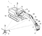
図1は第1の実施の形態である油圧ショベルを示している。油圧ショベル1は、一般的な油圧ショベルと同様に、上部旋回体11、クローラを含む下部走行体12、掘削などの作業を行う作業機構を構成するブーム13、アーム14、バケット15、アーム14及びバケット15と共にリンク機構を構成する第1バケットリンク16a及び第2バケットリンク16b、ブーム13を駆動するブームシリンダ17、アーム14を駆動するアームシリンダ18、バケット15をバケットリンク16a,16bを含むリンク機構を介して駆動するバケットシリンダ19などから構成されている。
FIG. 1 shows a hydraulic excavator according to a first embodiment. Similar to a general excavator, the
上部旋回体11は、下部走行体12に回転可能に支持されており、旋回モータ(図示せず)によって下部走行体12に対して相対的に回転駆動される。ブーム13は、一端が上部旋回体11に回転可能に支持されており、ブームシリンダ17の伸縮に応じて上部旋回体11に対して相対的に回転駆動される。アーム14は、一端がブーム13の他端に回転可能に支持されており、アームシリンダ18の伸縮に応じてブーム13に対して相対的に回転駆動される。
The
バケット15は、アーム14の他端に回転可能に支持されており、第1バケットリンク16aは、一端がアーム14に回転可能に支持されており、第2バケットリンク16bは、一端がバケット15に回動可能に支持され、他端が第1バケットリンク16aの他端に回動可能に支持されている。第1バケットリンク16aは、バケットシリンダ19の伸縮に応じてアーム14に対して相対的に回転駆動される。バケット15は、第1バケットリンク16aと連動して駆動される第2バケットリンク16bにより、アーム14に対して相対的に回転駆動される。このような構成である油圧ショベル1はブームシリンダ17、アームシリンダ18、バケットシリンダ19を適切な位置に駆動することにより、バケット15を任意の位置、姿勢に駆動し、所望の作業を行うことができる。
The
油圧ショベル1は、ブーム13、アーム14、バケットリンク16aにそれぞれブーム傾斜センサ21、アーム傾斜センサ22、バケット傾斜センサ23が設置されている。本実施形態では、傾斜センサ21〜23は2軸又は3軸の加速度を測定し、重力方向に対する傾斜角度を検出するものとして説明する。油圧ショベル1は上部旋回体11に設置された車体傾斜センサ24を持ち、車体の左右方向の傾斜角度θr(ロール角度)と前後方向の傾斜角度θp(ピッチ角度)を検出可能な構成となっている。
In the
各傾斜センサ21〜24の信号は、上部旋回体11に設置された演算装置25に送られ、演算装置25内でバケット先端位置P6やバケット角度θbkを演算する。演算されたバケット先端位置P6やバケット角度θbkは、運転席内のモニタ26に表示することでガイダンス機能として運転者へ提供したり、作業機構の動作を制御するためのフィードバック情報として用いられる。
Signals from the
以下、各傾斜センサ信号からバケット先端位置P6とバケット角度θbkを演算する方法について図1を用いて説明する。まず、演算に必要な各点P0〜P5を定義する。
Hereinafter, a method of calculating the bucket tip position P 6 and the bucket angle θ bk from each inclination sensor signal will be described with reference to FIG. First, define the
点P0は、上部旋回体11とブーム13との回転対偶部の回転軸上にあり、上部旋回体11、ブーム13又は両者の回転対偶部に挿入されたピン(図示せず)のいずれかの構造物の右端とする。点P1は、ブーム13とアーム14との回転対偶部の回転軸上にあり、ブーム13、アーム14又は両者の回転対偶部に挿入されたピン(図示せず)のいずれかの構造物の右端とする。
Point P 0 is on the rotation axis of the rotating pair of the
点P2は、アーム14とバケットリンク16aとの回転対偶部の回転軸上にあり、アーム14、バケットリンク16a又は両者の回転対偶部に挿入されたピン(図示せず)のいずれかの構造物の右端とする。
Point P 2 is located on the rotation axis of the rotary pair section of the
点P3は、バケットリンク16aとバケットシリンダ19との回転対偶部の回転軸上にあり、バケットリンク16a、バケットシリンダ19又は両者の回転対偶部に挿入されたピン(図示せず)のいずれかの構造物の右端とする。
Point P 3 is located on the rotation axis of the rotary pair section of the
点P4は、アーム14とバケット15との回転対偶部の回転軸上にあり、アーム14、バケット15又は両者の回転対偶部に挿入されたピン(図示せず)のいずれかの構造物の右端とする。
Point P 4 is located on the rotation axis of the rotary pair section of the
点P5は、バケット15とバケットリンク16aとの間に挿入されるバケットリンク16bと、バケット15との回転対偶部の回転軸上にあり、バケット15、バケットリンク16b又は両者の回転対偶部に挿入されたピン(図示せず)のいずれかの構造物の右端とする。
Point P 5 has a
点P6は、バケット15の先端且つバケット15の右端とする。本実施形態では、バケット先端位置P6は、点P0に原点をもち、上部旋回体11の前方向にX軸(XB)、左方向にY軸(YB)、上方向にZ軸(ZB)を持つ車体座標系ΣBで表すものとする。
Point P 6 is the tip of
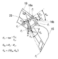
点P1〜P6をXBZB平面に投影した点をP1’〜P6’とし、線分P0P1’の長さをLbm、線分P1’P4’の長さをLam、線分P4’P6’の長さをLbk、線分P1’P2’の長さをLp2、線分P2’P3’の長さをLbklとし、線分P1’P4’に対して線分P1’P2’の成す角度をリンクオフセット角度θp2とする。また、水平面と上部旋回体11とのYB軸回りの角度を車体ピッチ角度θp(図示せず)、水平面と線分P0P1’の成す角度をブーム角度θbm、水平面と線分P1’P4’の成す角度をアーム角度θam、水平面と線分P2’P3’の成す角度をバケットリンク角度θbkl、水平面と線分P4’P6’の成す角度をバケット角度θbkとすると、XBZB平面に投影したバケット先端位置P6’は下記の式で表される。
The points obtained by projecting the

ここで、P6’x B、P6’z Bはそれぞれ座標系ΣBにおけるバケット先端位置P6のXB軸方向距離(XB座標)、ZB軸方向距離(ZB座標)を示す。車体ピッチ角度θpは車体傾斜センサ24によって検出される。ブーム角度θbmはブーム傾斜センサ21、アーム角度θamはアーム傾斜センサ22、バケット角度θbkはバケット傾斜センサ23によって得られるバケットリンク角度θbklとアーム角度θamから求めることができる。
Here, P 6′x B and P 6′z B indicate the X B axis direction distance (X B coordinate) and the Z B axis direction distance (Z B coordinate) of the bucket tip position P 6 in the coordinate system ΣB, respectively. The vehicle body pitch angle θ p is detected by the vehicle
各傾斜センサ21〜23からの各角度の求め方を図2〜図4を用いて説明する。
A method for obtaining each angle from each of the
図2はブーム傾斜センサ21の出力からブーム角度θbmを求める方法を模式的に示した図である。ブーム傾斜センサ21は内部に少なくとも2軸の方向の加速度を検出する加速度センサを持っており、ブーム傾斜センサ21に固定され座標系ΣBのY軸と平行なY軸を持つ座標系をΣS1とすると、ΣS1のX軸(XS1)とZ軸(ZS1)の2軸方向の加速度を検出できる。ブーム傾斜センサ21のXS1軸方向の加速度検出値をax1、ZS1軸方向の加速度検出値をaz1とすると、ブーム傾斜センサ21の水平方向に対する傾斜角度θs1は、
![]()
![]()
図3はアーム傾斜センサ22の出力からアーム角度θamを求める方法を模式的に示した図である。アーム傾斜センサ22もブーム傾斜センサ21と同様に内部に少なくとも2軸の方向の加速度を検出する加速度センサを持っており、アーム傾斜センサ22に固定され座標系ΣBのY軸と平行なY軸を持つ座標系をΣS2とすると、ΣS2のX軸(XS2)とZ軸(ZS2)の2軸方向の加速度を検出できる。アーム傾斜センサ22のXS2軸方向の加速度検出値をax2、ZS2軸方向の加速度検出値をaz2とすると、アーム傾斜センサ22の水平方向に対する傾斜角度θs2は、
![]()
![]()
図4はバケット傾斜センサ23の出力とアーム角度θamからバケット角度θbkを求める方法を模式的に示した図である。バケット傾斜センサ23もブーム傾斜センサ21やアーム傾斜センサ22と同様に内部に少なくとも2軸の方向の加速度を検出する加速度センサを持っており、バケット傾斜センサ23に固定され座標系ΣBのY軸と平行なY軸を持つ座標系をΣS3とすると、座標系ΣS3のX軸(XS3)とZ軸(ZS3)の2軸方向の加速度を検出できる。バケット傾斜センサ23のXS3軸方向の加速度検出値をax3、ZS3軸方向の加速度検出値をaz3とすると、バケット傾斜センサ23の水平方向に対する傾斜角度θs3は、
![]()
![]()
![]()
![]()
これまでの説明の通り、各傾斜センサの検出値からバケット先端位置P6やバケット角度を演算することができ、これらの演算は、演算装置25内で行われる。ただし、ブーム傾斜センサ21、アーム傾斜センサ22、バケット傾斜センサ23の取付角度θm1,θm2,θm3と、作業機構の各部寸法Lbm,Lam,Lbkは事前に把握しておかなければならない。各部寸法は設計情報から参照することができるが、取付角度は実際の車体毎に高精度に較正しなければならない。本発明は、この取付角度θm1,θm2,θm3を高精度且つ容易に較正する方法を提供するものである。
As described so far, the bucket tip position P 6 and the bucket angle can be calculated from the detection values of the respective inclination sensors, and these calculations are performed in the
なお、本実施形態では、車体傾斜センサ24は上部旋回体11に対して取付角度がゼロとなるように取付けられているとし、車体ピッチ角度θp及び車体ロール角度θrは車体傾斜センサ24の検出値から直接得られるものとするが、車体傾斜センサに関しては、取付角度がバケット先端位置P6の演算に影響するほどの大きさであれば、180°旋回した時のセンサの検出値から取付角度を較正するなどの広く世の中で用いられている方法を活用すればよい。
In the present embodiment, the vehicle
図5〜図7を用いて、本実施形態における本発明の内容である油圧ショベルの傾斜センサ較正方法を説明する。 The tilt sensor calibration method for a hydraulic excavator, which is the content of the present invention in this embodiment, will be described with reference to FIGS.
図5は較正方法を示す油圧ショベル1と外部計測装置3の斜視図である。外部計測装置3は例えばトータルステーションのような三次元空間上の任意の点の位置を計測可能なものである。外部計測装置3に固定の座標系をΣAとし、座標系ΣAのZ軸(ZA)が重力方向に対して平行となるように外部計測装置3は設置される。つまり、座標系ΣAのX軸(XA)とY軸(YA)を含む平面は水平面と等しくなる。本発明の較正方法は、油圧ショベル1の4つの点P0,P1,P2,P3の三次元位置を外部計測装置3により計測し、得られた三次元位置から各傾斜センサ21〜23の取付角度θm1,θm2,θm3を求めるものである。
FIG. 5 is a perspective view of the
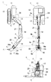
図6は油圧ショベル1の右側面、上面、正面を示す三面図であり、図7は図6の油圧ショベル1のリンク構造のみを模式的に示した三面図である。油圧ショベル1は、これらの図に示す通りXB軸回りにロール角度θr傾いているとする。この場合、XAYA平面とYB軸との成す角がθrとなる。また、点P0と点P1のYB軸方向距離をLbmy、点P1と点P2のYB軸方向距離をLp2y’、点P2と点P3のYB軸方向距離をLbklyとする。外部計測装置3によって計測される三次元位置は、座標系ΣAでの三次元座標となる。つまり、外部計測装置3によって計測される点P0の位置は、XA軸方向にP0x A、YA軸方向にP0y A、ZA軸方向にP0z Aとなる。点P1〜P6も同様である。
6 is a trihedral view showing the right side, top surface, and front of the
各傾斜センサの取付角度θm1,θm2,θm3は、ブーム角度θbm、アーム角度θam、バケットリンク角度θbkl、及びその時の各傾斜センサ21〜23の出力から得られる傾斜角度θs1,θs2,θs3を基に、算出することができる。ブーム角度θbm、アーム角度θam及びバケットリンク角度θbklは、外部計測装置3で計測された各点P0,P1,P2,P3の三次元位置を基に、以下の式を用いて求めることができる。
The mounting angles θ m1 , θ m2 , and θ m3 of the tilt sensors are the boom angle θ bm , the arm angle θ am , the bucket link angle θ bkl , and the tilt angle θ s1 obtained from the outputs of the
この時の各傾斜センサ21〜23の傾斜角度θs1,θs2,θs3を各傾斜センサ21〜23の検出値から求めることにより、以下の式で各センサの取付角度θm1,θm2,θm3を求めることができる。
By obtaining the inclination angles θ s1 , θ s2 , θ s3 of the
上記によって各傾斜センサ21〜23の取付角度θm1,θm2,θm3を得ることができ、このパラメータと傾斜センサ21〜23の検出値θs1,θs2,θs3からこれまでの説明の通りバケット先端位置P6’x B ,P6’z Bを求めることができる。
The mounting angles θ m1 , θ m2 , and θ m3 of the
以上の説明からわかる通り、本実施形態の油圧ショベルの傾斜センサ較正方法は、作業機構の3つの稼動部(ブーム13、アーム14、バケットリンク16a)の回転対偶部の三次元位置を、外部計測装置3により計測する第1ステップと、第1ステップで得られた回転対偶部の三次元位置、及び作業機構の各部の寸法情報を基に、各稼動部の傾斜角度を演算する第2ステップと、各傾斜センサ21〜23から得られた検出値θs1,θs2,θs3、及び第2ステップで得られた各稼動部の傾斜角度θbm,θam,θbklを基に、各傾斜センサ21〜23の較正パラメータである取付角度θm1,θm2,θm3を演算する第3ステップとから成る。
As can be seen from the above description, the hydraulic excavator tilt sensor calibration method according to the present embodiment externally measures the three-dimensional position of the rotating pair of the three operating parts (
具体的には、油圧ショベル1を任意の姿勢に静止させ、外部計測装置3によって4つの点P1,P1,P2,P3の三次元位置を計測する。その後、モニタ26を介して演算装置25へ較正パラメータ演算ステップの開始を指示し、計測によって得られた複数の三次元位置をモニタ26を介して演算装置25へ入力する。或いは、外部計測装置3とモニタ26もしくは演算装置25が、図示しない有線または無線通信装置により接続されており、外部計測装置3の計測によって得られた複数の三次元位置が通信により演算装置25へ送られる。演算装置25では、各傾斜センサ20〜23の検出値から車体ロール角度θrと各傾斜センサ21〜23の傾斜角度θs1,θs2,θs3を取得し、入力された複数の三次元位置と車体ロール角度θrから作業機構の各稼動部の傾斜角度θbm,θam,θbklを演算し、これらの演算結果と各傾斜センサ21〜23の傾斜角度θs1,θs2,θs3から各傾斜センサ21〜23の取付角度θm1,θm2,θm3を演算し、較正パラメータとして保存する。以降のバケット先端位置P6の演算には、保存された較正パラメータを用いる。
Specifically, the
較正パラメータとしての取付角度θm1,θm2,θm3の演算精度を確保するためには、外部計測装置3により、油圧ショベル1の作業機構の各回転対偶部の中心をできるだけ正確に計測する必要がある。一方、多くの油圧ショベル1では、外観からわかる回転対偶部は正確に中心を示す何らかの目印等があるわけではない。そのため、本実施形態では、図8に示す通り回転対偶部の中心を示す目印として、マーカ4を設けている。なお、図8ではバケット15付近のみ図示しているが、ブーム13やアーム14の回転対偶部に設けるマーカに関しても同様である。
In order to ensure the calculation accuracy of the mounting angles θ m1 , θ m2 , and θ m3 as calibration parameters, it is necessary to measure the center of each rotating pair of the working mechanism of the
トータルステーション等の外部計測装置3はレーザ光を目標位置に照射し、距離や角度を計測する。このため、マーカ等の目印があれば、何もない場合に比べて精度良くレーザ光を目的の場所に照射することができ、得られる三次元位置の計測結果の精度が向上する。また、マーカ4の代わりにレーザ光を入射方向に反射するプリズム5(コーナーキューブ)等を用いれば、レーザ光による計測の精度が向上する。このため、図9に示す通りプリズム5を治具6を用いて回転対偶部に取付けてもよい。図9では、作業機構の回転対偶部に挿入されたピン27と、そのピン27に取付けるプリズム5と治具6を示している。この場合、作業機構の各回転対偶部にテーパ穴28を設け、治具はそのテーパ穴28に嵌合する円すい部61とマグネット62を備えることで、各回転対偶部の回転軸上に容易かつ精度良くプリズム5を取付けることができる。なお、マーカ4やプリズム取付治具6の構成は本実施形態に示すものに限るものではなく、同等の機能を有していればよいことは言うまでもない。
The
本実施形態の油圧ショベルの較正方法は、次のような特徴を持つ。まず、油圧ショベル1の作業機構を動かす必要が無いため、狭い空間での較正作業が可能である。また、基準姿勢に位置合わせする必要もなく、最低4回の外部計測装置3による計測を行うのみでよいため、これまでの方法に比べて大幅に較正作業の時間を短縮することができる。加えて、車体や作業機構を動かすオペレータを必要としないため、外部計測装置3を用いる作業者1名のみで容易に較正作業を実施できる。
The method for calibrating a hydraulic excavator of this embodiment has the following characteristics. First, since it is not necessary to move the working mechanism of the
本発明の第2の実施形態における較正方法について、第1の実施形態との相違点を中心に説明する。 A calibration method according to the second embodiment of the present invention will be described focusing on differences from the first embodiment.
本実施形態における油圧ショベル1では、第1バケットリンク16aに代えてバケット15にバケット傾斜センサ23を設置し(図8中点線で示す)、点P0,P1,P2,P3に代えて点P0,P1,P4,P6の三次元位置を計測する。
In the
本実施形態においても、第1の実施形態と同様に、各傾斜センサ21〜23の取付角度θm1,θm2,θm3を較正することができる。但し、本実施形態で各傾斜センサ21〜23の取付角度θm1,θm2,θm3を演算する際に使用する式は、以下のようになる。ただし、Lbkyは点P4と点P6のYB軸方向距離である。
Also in this embodiment, the mounting angles θ m1 , θ m2 , and θ m3 of the
本実施形態によれば、傾斜センサ23をバケット15に直接設置し、点P3に代えてバケット先端位置P6の三次元位置を計測することにより、バケット15を駆動するリンク機構の寸法情報(第1の実施形態における関数f)を用いずに傾斜センサ23の取付角度θm3が求められるため、バケット傾斜センサ23の較正精度を向上させることが可能となる。
According to this embodiment, the
また、第1バケットリンク16aの基端側の回転軸上にある点P2に代えてアーム14の先端側の回転軸上にある点P4の三次元位置を計測することにより、リンクオフセット角度θp2を用いずにアーム傾斜角度θamを求めることができるため、アーム傾斜センサ22の較正精度を向上させることが可能となる。
Also, by measuring the three-dimensional position of the
図10を用いて本発明の第3の実施形態を説明する。本実施形態が第1の実施形態と異なる点は、4つのマーカ又はプリズムを取付治具を介して設置した点のみであり、それ以外の構成は同様であるため、重複する部分は説明を省略する。 A third embodiment of the present invention will be described with reference to FIG. This embodiment is different from the first embodiment only in that four markers or prisms are installed via a mounting jig, and the other configurations are the same, so the overlapping parts are not described. To do.
本実施形態の特徴は、4つのマーカ又はプリズム(4つの点P0,P1,P2,P3)がXBZB平面(又はブーム13の回動平面)と平行な同一平面上に配置されるように構成した点にある。このように構成するために、本実施形態では上部旋回体11とブーム13との回転対偶部の回転軸上、ブーム13とアーム14との回転対偶部の回転軸上、アーム14とバケットリンク16aとの回転対偶部の回転軸上、バケットリンク16aとバケットシリンダ19との回転対偶部の回転軸上のそれぞれに、取付治具6a,6b,6c,6dを介してマーカ又はプリズムを設置している。
Features of this embodiment, the four markers or prisms (four points P 0, P 1, P 2 , P 3) is X B Z B plane (or rotation plane of the boom 13) parallel to the same plane The point is that they are arranged. In order to configure in this way, in this embodiment, on the rotating shaft of the rotating pair of the
取付治具6aのYB軸上の長さをLxとすると、取付治具6bのYB軸上の長さはLx+Lbmy、取付治具6cのYB軸上の長さはLx+Lp2y、取付治具6dのYB軸上の長さはLx+Lbklyとなる。このように構成することにより、作業機構の点P0に対する点P1,P2,P3のYB軸方向のオフセットLbmy,Lp2y,Lbklyが全て0となるため、計算が容易になるだけでなく、外部計測装置3での計測値である各部の三次元位置から寸法値Lbm,Lp2,Lbklも下記の式にて得られる。
When the length of the Y B axis of the mounting
ブーム角度θbm、アーム角度θam、バケットリンク角度θblkは次式によって得られる。 The boom angle θ bm , the arm angle θ am , and the bucket link angle θ blk are obtained by the following equations.
上記の演算結果を基に、第1の実施形態で説明した方法により各傾斜センサ21〜23の較正が可能となる。
Based on the above calculation results, the
本実施形態によれば、4つの点P0,P1,P2,P3の三次元位置から実機の作業機構の各部寸法Lbm,Lp2,Lbklが得られるため、製造誤差等の影響が考慮されたより精度の高い較正が可能となる。また、較正の際に得られた実機の作業機構の各部寸法Lbm,Lbklの値を保持しておき、以降のバケット先端位置P6の演算にも使用することにより、バケット先端位置P6の演算精度を向上させることも可能となる。 According to the present embodiment, the dimensions L bm , L p2 , and L bkl of the working mechanism of the actual machine are obtained from the three-dimensional positions of the four points P 0 , P 1 , P 2 , and P 3 . A more accurate calibration considering the influence is possible. Moreover, various dimensions L bm of actual working mechanism obtained during calibration, holds the value of L bkl, by also be used in the calculation of the subsequent bucket tip position P 6, the bucket tip position P 6 It is also possible to improve the calculation accuracy.
以上、本発明の実施の形態について詳述したが、本発明は、上記した実施形態に限定されるものではなく、様々な変形例が含まれる。例えば、上記した実施形態は、本発明を分かり易く説明するために詳細に説明したものであり、必ずしも説明した全ての構成を備えるものに限定されるものではない。また、ある実施形態の構成に他の実施形態の構成の一部を加えることも可能であり、ある実施形態の構成の一部を削除し、あるいは、他の実施形態の一部と置き換えることも可能である。 As mentioned above, although embodiment of this invention was explained in full detail, this invention is not limited to above-described embodiment, Various modifications are included. For example, the above-described embodiment has been described in detail for easy understanding of the present invention, and is not necessarily limited to one having all the configurations described. In addition, a part of the configuration of another embodiment can be added to the configuration of a certain embodiment, and a part of the configuration of a certain embodiment can be deleted or replaced with a part of another embodiment. Is possible.
1…油圧ショベル(建設機械)、11…上部旋回体(車体)、12…下部走行体、13…ブーム(第1稼動部)、14…アーム(第2稼動部)、15…バケット(第3稼動部(本体部))、16a…第1バケットリンク(第3稼動部(第1連結部))、16b…第2バケットリンク(第3稼動部(第2連結部))、17…ブームシリンダ、18…アームシリンダ、19…バケットシリンダ、21…ブーム傾斜センサ(第1角度検出部)、22…アーム傾斜センサ(第2角度検出部)、23…バケット傾斜センサ(第3角度検出部)、24…車体傾斜センサ、25…演算装置、26…モニタ、27…ピン、28…テーパ穴、3…外部計測装置、4…マーカ、5…プリズム、6…治具、61…円すい部、62…マグネット。
DESCRIPTION OF
Claims (7)
前記車体に回転可能に支持された第1稼動部と、
前記第1稼動部に回転可能に支持された第2稼動部と、
前記第2稼動部に回転可能に支持された第3稼動部と、
前記第1稼動部に第1取付角度で取付けられ、前記第1稼動部の傾斜角度を検出する第1角度検出部と、
前記第2稼動部に第2取付角度で取付けられ、前記第1稼動部の傾斜角度を検出する第2角度検出部と、
前記第3稼動部に第3取付角度で取付けられ、前記第1稼動部の傾斜角度を検出する第3角度検出部と、
前記第1乃至第3取付角度、前記第1乃至第3角度検出部で各々検出された前記第1乃至第3稼動部の傾斜角度、及び前記第1乃至第3稼動部の寸法情報を基に、前記第3稼動部上の予め設定された位置を演算するように構成された演算装置とを有する建設機械の前記第1乃至第3取付角度を較正する、建設機械の較正方法において、
前記車体に対する前記第1稼動部の回転軸上にある第1計測点、前記第1稼動部に対する前記第2稼動部の回転軸上にある第2計測点、前記第2稼動部に対する前記第3稼動部の回転軸上にある第3計測点、及び前記第3稼動部上にある第4計測点を外部計測装置で計測する第1ステップと、
少なくとも前記第1ステップで計測された前記第1乃至第4計測点を基に、前記第1乃至第3稼動部の傾斜角度を前記演算装置によって演算する第2ステップと、
前記第2ステップで演算された前記第1乃至第3稼動部の傾斜角度、及び前記第1乃至第3角度検出部で検出された傾斜角度を基に、前記第1乃至第3取付角度を演算する第3ステップと
を備えたことを特徴とする建設機械の較正方法。 The car body,
A first working part rotatably supported by the vehicle body;
A second working part rotatably supported by the first working part;
A third working part rotatably supported by the second working part;
A first angle detector that is attached to the first working part at a first attachment angle and detects an inclination angle of the first working part;
A second angle detector that is attached to the second working part at a second attachment angle and detects an inclination angle of the first working part;
A third angle detector that is attached to the third working part at a third attachment angle and detects an inclination angle of the first working part;
Based on the first to third mounting angles, the inclination angles of the first to third working parts detected by the first to third angle detecting parts, respectively, and the dimension information of the first to third working parts. In the construction machine calibration method for calibrating the first to third mounting angles of the construction machine having a computing device configured to compute a preset position on the third working unit,
A first measurement point on the rotation axis of the first operating part relative to the vehicle body; a second measurement point on the rotation axis of the second operating part relative to the first operating part; and the third measurement point on the second operating part. A first step of measuring, with an external measuring device, a third measurement point on the rotation axis of the operating unit and a fourth measurement point on the third operating unit;
A second step of calculating an inclination angle of the first to third working parts by the calculation device based on at least the first to fourth measurement points measured in the first step;
The first to third attachment angles are calculated based on the inclination angles of the first to third working parts calculated in the second step and the inclination angles detected by the first to third angle detection parts. A construction machine calibration method comprising: a third step.
前記第3稼動部は、
前記第2稼動部に回転可能に支持された本体部と、
前記第2稼動部に一端が回転可能に支持された第1連結部と、
前記第1連結部の他端に一端が回転可能に支持され、前記本体部に他端が回転可能に支持された第2連結部とを有し、
前記第3角度検出部は、前記本体部に取付けられ、
前記第3計測点は、前記第2稼動部に対する前記第1連結部の回転軸上にあり、
前記第4計測点は、前記第1連結部に対する前記第2連結部の回転軸上にあることを特徴とする建設機械の較正方法。 The construction machine calibration method according to claim 1,
The third working part is
A main body part rotatably supported by the second working part;
A first connecting part having one end rotatably supported by the second working part;
One end is rotatably supported at the other end of the first connecting portion, and the second connecting portion is rotatably supported at the other end of the main body portion.
The third angle detector is attached to the main body,
The third measurement point is on a rotation axis of the first connection part with respect to the second working part,
The construction machine calibration method, wherein the fourth measurement point is on a rotation axis of the second connection part with respect to the first connection part.
前記第1乃至第4計測点は、前記第1稼動部の回動平面と平行な同一平面上に配置されたことを特徴とする建設機械の較正方法。 The construction machine calibration method according to claim 2,
The construction machine calibration method, wherein the first to fourth measurement points are arranged on the same plane parallel to the rotation plane of the first working part.
前記車体に回転可能に支持された第1稼動部と、
前記第1稼動部に回転可能に支持された第2稼動部と、
前記第2稼動部に回転可能に支持された第3稼動部と、
前記第1稼動部に第1取付角度で取付けられ、前記第1稼動部の傾斜角度を検出する第1角度検出部と、
前記第2稼動部に第2取付角度で取付けられ、前記第1稼動部の傾斜角度を検出する第2角度検出部と、
前記第3稼動部に第3取付角度で取付けられ、前記第1稼動部の傾斜角度を検出する第3角度検出部と、
前記第1乃至第3取付角度、前記第1乃至第3角度検出部で各々検出された前記第1乃至第3稼動部の傾斜角度、及び前記第1乃至第3稼動部の寸法情報を基に、前記第3稼動部上の予め設定された位置を演算するように構成された演算装置とを有する建設機械において、
前記車体に対する前記第1稼動部の回転軸上にある第1計測点、前記第1稼動部に対する前記第2稼動部の回転軸上にある第2計測点、前記第2稼動部に対する前記第3稼動部の回転軸上にある第3計測点、及び前記第3稼動部上にある第4計測点のそれぞれに外部計測装置で計測可能な第1乃至第4マーカを備え、
前記演算装置は、少なくとも前記外部計測装置で計測された前記第1乃至第4計測点の三次元位置を基に、前記第1乃至第3稼動部の傾斜角度を演算し、前記第1乃至第3稼動部の傾斜角度、及び前記第1乃至第3角度検出部で検出された傾斜角度を基に、前記第1乃至第3取付角度を演算するように構成されたことを特徴とする建設機械。 The car body,
A first working part rotatably supported by the vehicle body;
A second working part rotatably supported by the first working part;
A third working part rotatably supported by the second working part;
A first angle detector that is attached to the first working part at a first attachment angle and detects an inclination angle of the first working part;
A second angle detector that is attached to the second working part at a second attachment angle and detects an inclination angle of the first working part;
A third angle detector that is attached to the third working part at a third attachment angle and detects an inclination angle of the first working part;
Based on the first to third mounting angles, the inclination angles of the first to third working parts detected by the first to third angle detecting parts, respectively, and the dimension information of the first to third working parts. In a construction machine having a calculation device configured to calculate a preset position on the third working unit,
A first measurement point on the rotation axis of the first operating part relative to the vehicle body; a second measurement point on the rotation axis of the second operating part relative to the first operating part; and the third measurement point on the second operating part. First to fourth markers that can be measured by an external measuring device are provided at each of the third measurement point on the rotation axis of the operating unit and the fourth measurement point on the third operating unit,
The arithmetic device calculates an inclination angle of the first to third working parts based on at least a three-dimensional position of the first to fourth measurement points measured by the external measurement device, and A construction machine configured to calculate the first to third attachment angles on the basis of the inclination angle of three operating parts and the inclination angle detected by the first to third angle detection parts. .
前記第3稼動部は、
前記第2稼動部に回転可能に支持された本体部と、
前記第2稼動部に一端が回転可能に支持された第1連結部と、
前記第1連結部の他端に一端が回転可能に支持され、前記本体部に他端が回転可能に支持された第2連結部とを有し、
前記第3角度検出部は、前記本体部に取付けられ、
前記第3計測点は、前記第2稼動部に対する前記第1連結部の回転軸上にあり、
前記第4計測点は、前記第1連結部に対する前記第2連結部の回転軸上にあることを特徴とする建設機械。 The construction machine according to claim 4,
The third working part is
A main body part rotatably supported by the second working part;
A first connecting part having one end rotatably supported by the second working part;
One end is rotatably supported at the other end of the first connecting portion, and the second connecting portion is rotatably supported at the other end of the main body portion.
The third angle detector is attached to the main body,
The third measurement point is on a rotation axis of the first connection part with respect to the second working part,
The construction machine, wherein the fourth measurement point is on a rotation axis of the second connection portion with respect to the first connection portion.
前記第1乃至第4マーカは、前記第1稼動部の回動平面と平行な同一平面上に設置されたことを特徴とする建設機械。 The construction machine according to claim 5,
The construction machine according to claim 1, wherein the first to fourth markers are installed on the same plane parallel to the rotation plane of the first working part.
前記車体と前記第1稼動部との第1回転対偶部、前記第1稼動部と前記第2稼動部との第2回転対偶部、前記第2稼動部と前記第1連結部の第3回転対偶部、及び前記第1連結部と前記第2連結部との第4回転対偶部は、それぞれの回転軸を中心とするテーパ穴を有し、
前記第1乃至第4マーカは、前記第1乃至第4回転対偶部の各テーパ穴に嵌合するように形成された円すい部を有する治具を介して、前記第1乃至第4回転対偶部にそれぞれ取付けられることを特徴とする建設機械。 The construction machine according to claim 5,
A first rotating pair of the vehicle body and the first operating part; a second rotating pair of the first operating part and the second operating part; a third rotation of the second operating part and the first connecting part. The paired part, and the fourth rotating paired part of the first connecting part and the second connecting part have tapered holes centered on the respective rotation axes,
The first to fourth rotating pair portions are connected to the first to fourth rotating pair portions via a jig having a conical portion formed so as to be fitted into each tapered hole of the first to fourth rotating pair portions. Construction machine characterized in that it is mounted on each.
Priority Applications (1)
| Application Number | Priority Date | Filing Date | Title |
|---|---|---|---|
| JP2016070141A JP6546558B2 (en) | 2016-03-31 | 2016-03-31 | Construction machine and calibration method for construction machine |
Applications Claiming Priority (1)
| Application Number | Priority Date | Filing Date | Title |
|---|---|---|---|
| JP2016070141A JP6546558B2 (en) | 2016-03-31 | 2016-03-31 | Construction machine and calibration method for construction machine |
Publications (2)
| Publication Number | Publication Date |
|---|---|
| JP2017181340A true JP2017181340A (en) | 2017-10-05 |
| JP6546558B2 JP6546558B2 (en) | 2019-07-17 |
Family
ID=60004444
Family Applications (1)
| Application Number | Title | Priority Date | Filing Date |
|---|---|---|---|
| JP2016070141A Active JP6546558B2 (en) | 2016-03-31 | 2016-03-31 | Construction machine and calibration method for construction machine |
Country Status (1)
| Country | Link |
|---|---|
| JP (1) | JP6546558B2 (en) |
Cited By (13)
| Publication number | Priority date | Publication date | Assignee | Title |
|---|---|---|---|---|
| WO2018164079A1 (en) * | 2017-03-06 | 2018-09-13 | 株式会社トプコン | Method for acquiring tilt sensor correction amount in construction work machinery |
| WO2019059092A1 (en) | 2017-09-21 | 2019-03-28 | 株式会社フジクラ | Antenna device |
| WO2019225133A1 (en) * | 2018-05-22 | 2019-11-28 | 株式会社小松製作所 | Hydraulic shovel and system |
| CN111226009A (en) * | 2018-09-25 | 2020-06-02 | 日立建机株式会社 | External shape measuring system for working machine, external shape display system for working machine, control system for working machine, and working machine |
| JP2021063825A (en) * | 2017-03-06 | 2021-04-22 | 株式会社トプコン | Acquisition method of correction amount of inclination sensor in construction work machine |
| WO2022215373A1 (en) * | 2021-04-08 | 2022-10-13 | 株式会社小松製作所 | Position estimating system, position estimating unit, work machine, and extension unit |
| US11592277B2 (en) | 2019-03-18 | 2023-02-28 | Deere & Company | Calibration kit for work machine |
| JP7357124B2 (en) | 2017-11-02 | 2023-10-05 | 株式会社トプコン | Targets, survey methods and programs |
| CN116852383A (en) * | 2023-09-05 | 2023-10-10 | 山东大学 | Automatic calibration device and method for zero position of mechanical arm |
| WO2023195417A1 (en) * | 2022-04-08 | 2023-10-12 | 日立建機株式会社 | Construction machine |
| WO2023228244A1 (en) * | 2022-05-23 | 2023-11-30 | 日本電気株式会社 | Information processing device, information processing method, and recording medium |
| WO2024010024A1 (en) * | 2022-07-08 | 2024-01-11 | 株式会社ニコン | Measuring method, and method for constructing structure |
| WO2024057846A1 (en) * | 2022-09-14 | 2024-03-21 | 株式会社小松製作所 | System and method for setting vehicle body coordinate system in work machine |
Citations (8)
| Publication number | Priority date | Publication date | Assignee | Title |
|---|---|---|---|---|
| JPH06322793A (en) * | 1993-05-11 | 1994-11-22 | Nachi Fujikoshi Corp | Method and device for calibrating angle detector working machine |
| JP2006194823A (en) * | 2005-01-17 | 2006-07-27 | Hitachi Constr Mach Co Ltd | Device for measuring positions of working tools for working machines |
| JP2012202061A (en) * | 2011-03-24 | 2012-10-22 | Komatsu Ltd | Calibration system and calibration method for hydraulic shovel |
| JP2012233353A (en) * | 2011-05-02 | 2012-11-29 | Komatsu Ltd | Calibration system for hydraulic shovel and calibration method for the hydraulic shovel |
| JP2013036243A (en) * | 2011-08-09 | 2013-02-21 | Topcon Corp | Control system for construction machine |
| WO2015040726A1 (en) * | 2013-09-19 | 2015-03-26 | 株式会社小松製作所 | Measurement jig |
| WO2015137527A1 (en) * | 2015-03-27 | 2015-09-17 | 株式会社小松製作所 | Device for calibrating work machine and method for calibrating work machine parameters of work machine |
| JP2015224875A (en) * | 2014-05-26 | 2015-12-14 | Kyb株式会社 | Operation state detection system of work machine, and work machine |
-
2016
- 2016-03-31 JP JP2016070141A patent/JP6546558B2/en active Active
Patent Citations (8)
| Publication number | Priority date | Publication date | Assignee | Title |
|---|---|---|---|---|
| JPH06322793A (en) * | 1993-05-11 | 1994-11-22 | Nachi Fujikoshi Corp | Method and device for calibrating angle detector working machine |
| JP2006194823A (en) * | 2005-01-17 | 2006-07-27 | Hitachi Constr Mach Co Ltd | Device for measuring positions of working tools for working machines |
| JP2012202061A (en) * | 2011-03-24 | 2012-10-22 | Komatsu Ltd | Calibration system and calibration method for hydraulic shovel |
| JP2012233353A (en) * | 2011-05-02 | 2012-11-29 | Komatsu Ltd | Calibration system for hydraulic shovel and calibration method for the hydraulic shovel |
| JP2013036243A (en) * | 2011-08-09 | 2013-02-21 | Topcon Corp | Control system for construction machine |
| WO2015040726A1 (en) * | 2013-09-19 | 2015-03-26 | 株式会社小松製作所 | Measurement jig |
| JP2015224875A (en) * | 2014-05-26 | 2015-12-14 | Kyb株式会社 | Operation state detection system of work machine, and work machine |
| WO2015137527A1 (en) * | 2015-03-27 | 2015-09-17 | 株式会社小松製作所 | Device for calibrating work machine and method for calibrating work machine parameters of work machine |
Cited By (22)
| Publication number | Priority date | Publication date | Assignee | Title |
|---|---|---|---|---|
| JP2021063825A (en) * | 2017-03-06 | 2021-04-22 | 株式会社トプコン | Acquisition method of correction amount of inclination sensor in construction work machine |
| JP2018146408A (en) * | 2017-03-06 | 2018-09-20 | 株式会社トプコン | Acquisition method of inclination sensor correction amount in construction work machine |
| WO2018164079A1 (en) * | 2017-03-06 | 2018-09-13 | 株式会社トプコン | Method for acquiring tilt sensor correction amount in construction work machinery |
| WO2019059092A1 (en) | 2017-09-21 | 2019-03-28 | 株式会社フジクラ | Antenna device |
| JP7357124B2 (en) | 2017-11-02 | 2023-10-05 | 株式会社トプコン | Targets, survey methods and programs |
| JP7045926B2 (en) | 2018-05-22 | 2022-04-01 | 株式会社小松製作所 | Hydraulic excavator, and system |
| US11713560B2 (en) | 2018-05-22 | 2023-08-01 | Komatsu Ltd. | Hydraulic excavator and system |
| WO2019225133A1 (en) * | 2018-05-22 | 2019-11-28 | 株式会社小松製作所 | Hydraulic shovel and system |
| CN111819333A (en) * | 2018-05-22 | 2020-10-23 | 株式会社小松制作所 | Hydraulic excavator and system |
| CN111819333B (en) * | 2018-05-22 | 2022-06-03 | 株式会社小松制作所 | Hydraulic excavator and system |
| JP2019203291A (en) * | 2018-05-22 | 2019-11-28 | 株式会社小松製作所 | Hydraulic shovel and system |
| CN111226009B (en) * | 2018-09-25 | 2022-03-04 | 日立建机株式会社 | External shape measuring system for working machine, external shape display system for working machine, control system for working machine, and working machine |
| CN111226009A (en) * | 2018-09-25 | 2020-06-02 | 日立建机株式会社 | External shape measuring system for working machine, external shape display system for working machine, control system for working machine, and working machine |
| JPWO2020065738A1 (en) * | 2018-09-25 | 2021-01-07 | 日立建機株式会社 | Work machine outer shape measurement system, work machine outer shape display system, work machine control system and work machine |
| US11592277B2 (en) | 2019-03-18 | 2023-02-28 | Deere & Company | Calibration kit for work machine |
| WO2022215373A1 (en) * | 2021-04-08 | 2022-10-13 | 株式会社小松製作所 | Position estimating system, position estimating unit, work machine, and extension unit |
| WO2023195417A1 (en) * | 2022-04-08 | 2023-10-12 | 日立建機株式会社 | Construction machine |
| WO2023228244A1 (en) * | 2022-05-23 | 2023-11-30 | 日本電気株式会社 | Information processing device, information processing method, and recording medium |
| WO2024010024A1 (en) * | 2022-07-08 | 2024-01-11 | 株式会社ニコン | Measuring method, and method for constructing structure |
| WO2024057846A1 (en) * | 2022-09-14 | 2024-03-21 | 株式会社小松製作所 | System and method for setting vehicle body coordinate system in work machine |
| CN116852383A (en) * | 2023-09-05 | 2023-10-10 | 山东大学 | Automatic calibration device and method for zero position of mechanical arm |
| CN116852383B (en) * | 2023-09-05 | 2023-12-08 | 山东大学 | Automatic calibration device and method for zero position of mechanical arm |
Also Published As
| Publication number | Publication date |
|---|---|
| JP6546558B2 (en) | 2019-07-17 |
Similar Documents
| Publication | Publication Date | Title |
|---|---|---|
| JP6546558B2 (en) | Construction machine and calibration method for construction machine | |
| JP5823046B1 (en) | Hydraulic excavator calibration system and calibration method | |
| KR101644409B1 (en) | Mobile working machine comprising a position control device of a working arm and method for controlling the position of a working arm of a mobile working machine | |
| JP5237409B2 (en) | Hydraulic excavator calibration apparatus and hydraulic excavator calibration method | |
| JP5237408B2 (en) | Hydraulic excavator calibration system and calibration method | |
| JP5759798B2 (en) | Construction machine control system | |
| JP5841300B1 (en) | Work machine calibration apparatus and work machine parameter calibration method | |
| JP5328830B2 (en) | Hydraulic excavator calibration apparatus and hydraulic excavator calibration method | |
| JP6864745B2 (en) | Determining Machine Rim Length and Angle Offset Using Laser Rangefinder | |
| JP2012233353A (en) | Calibration system for hydraulic shovel and calibration method for the hydraulic shovel | |
| CN109496245B (en) | Hydraulic excavator and correction method for hydraulic excavator | |
| JP6058218B2 (en) | Work vehicle and tilt angle acquisition method | |
| US9404745B2 (en) | Measurement jig | |
| WO2018164079A1 (en) | Method for acquiring tilt sensor correction amount in construction work machinery | |
| CN113494104A (en) | Positioning correction method for construction work machine and positioning correction controller therefor | |
| WO2019012649A1 (en) | Calibration method of work machine, calibration device, and calibration system of work machine | |
| JP4175727B2 (en) | Method for detecting elevation angle and turning angle of excavation boom in free section excavator | |
| JP7424960B2 (en) | Information acquisition system and information acquisition method | |
| US20180163363A1 (en) | Excavator Implement Length And Angle Offset Determination Using A Laser Distance Meter | |
| WO2023166885A1 (en) | Information calibration method | |
| EP4296433A1 (en) | Improved determination of an excavator swing boom angle based on an angular velocity ratio | |
| JP4067687B2 (en) | Method for confirming damage to moving parts of free section excavator | |
| JP2021001435A (en) | Work machine and control method thereof | |
| JP2001132388A (en) | Positioning device for tunnel work machine |
Legal Events
| Date | Code | Title | Description |
|---|---|---|---|
| A621 | Written request for application examination |
Free format text: JAPANESE INTERMEDIATE CODE: A621 Effective date: 20180821 |
|
| A977 | Report on retrieval |
Free format text: JAPANESE INTERMEDIATE CODE: A971007 Effective date: 20190424 |
|
| A131 | Notification of reasons for refusal |
Free format text: JAPANESE INTERMEDIATE CODE: A131 Effective date: 20190507 |
|
| A521 | Request for written amendment filed |
Free format text: JAPANESE INTERMEDIATE CODE: A523 Effective date: 20190603 |
|
| TRDD | Decision of grant or rejection written | ||
| A01 | Written decision to grant a patent or to grant a registration (utility model) |
Free format text: JAPANESE INTERMEDIATE CODE: A01 Effective date: 20190618 |
|
| A61 | First payment of annual fees (during grant procedure) |
Free format text: JAPANESE INTERMEDIATE CODE: A61 Effective date: 20190621 |
|
| R150 | Certificate of patent or registration of utility model |
Ref document number: 6546558 Country of ref document: JP Free format text: JAPANESE INTERMEDIATE CODE: R150 |