JP2017180462A - Variable nozzle mechanism - Google Patents

Variable nozzle mechanism Download PDF

Info

Publication number
JP2017180462A
JP2017180462A JP2017057526A JP2017057526A JP2017180462A JP 2017180462 A JP2017180462 A JP 2017180462A JP 2017057526 A JP2017057526 A JP 2017057526A JP 2017057526 A JP2017057526 A JP 2017057526A JP 2017180462 A JP2017180462 A JP 2017180462A
Authority
JP
Japan
Prior art keywords
arm
nozzle
contact surface
support shaft
curvature
Prior art date
Legal status (The legal status is an assumption and is not a legal conclusion. Google has not performed a legal analysis and makes no representation as to the accuracy of the status listed.)
Granted
Application number
JP2017057526A
Other languages
Japanese (ja)
Other versions
JP6597689B2 (en
Inventor
秋本 健太
Kenta Akimoto
健太 秋本
Current Assignee (The listed assignees may be inaccurate. Google has not performed a legal analysis and makes no representation or warranty as to the accuracy of the list.)
Toyota Industries Corp
Original Assignee
Toyota Industries Corp
Priority date (The priority date is an assumption and is not a legal conclusion. Google has not performed a legal analysis and makes no representation as to the accuracy of the date listed.)
Filing date
Publication date
Application filed by Toyota Industries Corp filed Critical Toyota Industries Corp
Priority to US15/469,632 priority Critical patent/US10563536B2/en
Priority to EP17163078.3A priority patent/EP3225787B1/en
Publication of JP2017180462A publication Critical patent/JP2017180462A/en
Application granted granted Critical
Publication of JP6597689B2 publication Critical patent/JP6597689B2/en
Active legal-status Critical Current
Anticipated expiration legal-status Critical

Links

Images

Classifications

    • FMECHANICAL ENGINEERING; LIGHTING; HEATING; WEAPONS; BLASTING
    • F01MACHINES OR ENGINES IN GENERAL; ENGINE PLANTS IN GENERAL; STEAM ENGINES
    • F01DNON-POSITIVE DISPLACEMENT MACHINES OR ENGINES, e.g. STEAM TURBINES
    • F01D17/00Regulating or controlling by varying flow
    • F01D17/10Final actuators
    • F01D17/12Final actuators arranged in stator parts
    • F01D17/14Final actuators arranged in stator parts varying effective cross-sectional area of nozzles or guide conduits
    • F01D17/16Final actuators arranged in stator parts varying effective cross-sectional area of nozzles or guide conduits by means of nozzle vanes
    • F01D17/165Final actuators arranged in stator parts varying effective cross-sectional area of nozzles or guide conduits by means of nozzle vanes for radial flow, i.e. the vanes turning around axes which are essentially parallel to the rotor centre line
    • FMECHANICAL ENGINEERING; LIGHTING; HEATING; WEAPONS; BLASTING
    • F02COMBUSTION ENGINES; HOT-GAS OR COMBUSTION-PRODUCT ENGINE PLANTS
    • F02BINTERNAL-COMBUSTION PISTON ENGINES; COMBUSTION ENGINES IN GENERAL
    • F02B37/00Engines characterised by provision of pumps driven at least for part of the time by exhaust
    • F02B37/12Control of the pumps
    • F02B37/24Control of the pumps by using pumps or turbines with adjustable guide vanes
    • FMECHANICAL ENGINEERING; LIGHTING; HEATING; WEAPONS; BLASTING
    • F05INDEXING SCHEMES RELATING TO ENGINES OR PUMPS IN VARIOUS SUBCLASSES OF CLASSES F01-F04
    • F05DINDEXING SCHEME FOR ASPECTS RELATING TO NON-POSITIVE-DISPLACEMENT MACHINES OR ENGINES, GAS-TURBINES OR JET-PROPULSION PLANTS
    • F05D2220/00Application
    • F05D2220/40Application in turbochargers
    • YGENERAL TAGGING OF NEW TECHNOLOGICAL DEVELOPMENTS; GENERAL TAGGING OF CROSS-SECTIONAL TECHNOLOGIES SPANNING OVER SEVERAL SECTIONS OF THE IPC; TECHNICAL SUBJECTS COVERED BY FORMER USPC CROSS-REFERENCE ART COLLECTIONS [XRACs] AND DIGESTS
    • Y02TECHNOLOGIES OR APPLICATIONS FOR MITIGATION OR ADAPTATION AGAINST CLIMATE CHANGE
    • Y02TCLIMATE CHANGE MITIGATION TECHNOLOGIES RELATED TO TRANSPORTATION
    • Y02T10/00Road transport of goods or passengers
    • Y02T10/10Internal combustion engine [ICE] based vehicles
    • Y02T10/12Improving ICE efficiencies

Landscapes

  • Engineering & Computer Science (AREA)
  • Mechanical Engineering (AREA)
  • General Engineering & Computer Science (AREA)
  • Chemical & Material Sciences (AREA)
  • Combustion & Propulsion (AREA)
  • Supercharger (AREA)
  • Control Of Turbines (AREA)

Abstract

PROBLEM TO BE SOLVED: To provide a variable nozzle mechanism capable of suppressing abrasion.SOLUTION: A variable nozzle mechanism includes a plurality of nozzle vanes, a plurality of arms 49 and a unison ring. The plurality of nozzle vanes are provided in a nozzle passage. Each of the plurality of arms has a pivot end and a free end, and the pivot end is integrally connected to the nozzle vane by a support shaft 47. At the unison ring, a plurality of grooves are formed. With each of the grooves of the unison ring, the free end of the arm is engaged respectively. The free end of the arm has a closed side contact surface 510 and an opening side contact surface 520. Each of the closed side contact surface 510 and the opening side contact surface 520 comes into contact with one of a pair of walls for forming the grooves of the unison ring respectively. In the closed side contact surface 510, the curvature on the side closer to the support shaft 47 is different from the curvature on the side farther from the support shaft 47.SELECTED DRAWING: Figure 3

Description

本発明は、ターボチャージャに用いられる可変ノズル機構に関する。   The present invention relates to a variable nozzle mechanism used in a turbocharger.

ターボチャージャは、スクロール通路内の排気ガスをタービンホイールに吹き付けて、タービンホイールを回転駆動する。従来、ターボチャージャには、ターボチャージャの特性を可変にするために、可変ノズル機構が採用されている。可変ノズル機構は、複数のノズルベーンの移動によって排気ガスの流路断面積を増減させ、タービンホイールに吹き付けられる排気ガスの流速を制御する。   The turbocharger blows the exhaust gas in the scroll passage to the turbine wheel to drive the turbine wheel to rotate. Conventionally, a variable nozzle mechanism has been employed in a turbocharger in order to make the characteristics of the turbocharger variable. The variable nozzle mechanism increases or decreases the flow passage cross-sectional area of the exhaust gas by moving a plurality of nozzle vanes, and controls the flow rate of the exhaust gas blown to the turbine wheel.

特開2014−224498号公報(特許文献1)には、可変ノズルのアームが係合するアーム嵌合溝をユニゾンリングに形成し、アーム嵌合溝の閉側溝壁面を凹型円弧状に形成し、開側溝壁面を凸型円弧状に形成する、可変ノズル機構が提案されている。   In JP 2014-224498 A (Patent Document 1), an arm fitting groove that engages an arm of a variable nozzle is formed in a unison ring, and a closed side groove wall surface of the arm fitting groove is formed in a concave arc shape. A variable nozzle mechanism has been proposed in which the open-side groove wall surface is formed in a convex arc shape.

特開2014−224498号公報JP 2014-224498 A

特許文献1には、アーム嵌合溝の壁面のうち、排気反力の作用によってアームと通常的に接触し合う閉側溝壁面を凹型円弧状に形成することによって、閉側溝壁面とアームとの間の接触応力を低減し、アームおよび閉側溝壁面の摩耗を低減することが開示されている。しかしながら、ノズルベーンの位置精度の悪化による過給遅れまたは排気不良を抑制するために、可変ノズル機構にはアームおよびユニゾンリングの摩耗のさらなる低減が求められており、従来の可変ノズル機構では必ずしも十分とはいえず更なる改良の余地がある。   In Patent Document 1, among the wall surfaces of the arm fitting groove, the closed side groove wall surface that normally comes into contact with the arm by the action of the exhaust reaction force is formed in a concave arc shape, so that the space between the closed side groove wall surface and the arm is formed. Reducing the contact stress of the arm and the wall surface of the closed groove is disclosed. However, the variable nozzle mechanism is required to further reduce the wear of the arm and unison ring in order to suppress supercharging delay or exhaust failure due to the deterioration of the position accuracy of the nozzle vane, and the conventional variable nozzle mechanism is not always sufficient. There is room for further improvement.

本発明の目的は、アームおよびユニゾンリングの摩耗を抑制することができる可変ノズル機構を提供することである。   An object of the present invention is to provide a variable nozzle mechanism that can suppress wear of an arm and a unison ring.

本発明に係る可変ノズル機構は、ターボチャージャに用いられ、ノズル通路を介してタービンブレードに吹き付けられる排気ガスを変動させる。可変ノズル機構は、複数のノズルベーンと、複数のアームと、ユニゾンリングとを備えている。複数のノズルベーンは、ノズル通路に設けられている。複数のアームは、各々が軸支端と自由端とを有しており、軸支端は支軸によってノズルベーンに一体に連結されている。ユニゾンリングには、複数の溝が形成されている。ユニゾンリングの溝の各々に、アームの自由端がそれぞれ係合している。アームとノズルベーンとは、ノズル通路の断面積を増大する開方向と減少する閉方向との両方にユニゾンリングが回転するとき、支軸を中心に一体に開方向と閉方向とに回転して、ノズル通路の断面積を変動可能である。アームの自由端は、アームの閉方向回転側と開方向回転側との一対の接触面を有している。一対の接触面の各々が、ユニゾンリングの溝を形成する一対の壁の一方にそれぞれ接触している。アームの接触面の一方は、ユニゾンリングの溝の壁面に向けた凸曲面をなすとともに、凸曲面の支軸に近い側と支軸から遠い側との曲率が異なる。   The variable nozzle mechanism according to the present invention is used in a turbocharger, and fluctuates exhaust gas blown to a turbine blade through a nozzle passage. The variable nozzle mechanism includes a plurality of nozzle vanes, a plurality of arms, and a unison ring. The plurality of nozzle vanes are provided in the nozzle passage. Each of the plurality of arms has a shaft support end and a free end, and the shaft support end is integrally connected to the nozzle vane by a support shaft. A plurality of grooves are formed in the unison ring. The free end of the arm is engaged with each of the grooves of the unison ring. When the unison ring rotates in both the opening direction that increases the cross-sectional area of the nozzle passage and the closing direction that decreases, the arm and the nozzle vane rotate integrally in the opening direction and the closing direction around the support shaft, The cross-sectional area of the nozzle passage can be varied. The free end of the arm has a pair of contact surfaces on the closing direction rotation side and the opening direction rotation side of the arm. Each of the pair of contact surfaces is in contact with one of the pair of walls forming the groove of the unison ring. One of the contact surfaces of the arm forms a convex curved surface toward the wall surface of the groove of the unison ring, and the curvatures of the convex curved surface near the support shaft and the side far from the support shaft are different.

上記可変ノズル機構において好ましくは、排気ガスの圧力はノズル通路を減少させる閉方向にノズルベーンに作用し、上記曲率を有するアームの接触面は、アームの回動の閉方向側に位置しているとともに、支軸から離れるにつれて曲率が小さくなっている。   Preferably, in the variable nozzle mechanism, the pressure of the exhaust gas acts on the nozzle vane in the closing direction for reducing the nozzle passage, and the contact surface of the arm having the curvature is located on the closing direction side of the arm rotation. The curvature decreases with increasing distance from the spindle.

上記可変ノズル機構において好ましくは、排気ガスの圧力はノズル通路を増大させる開方向にノズルベーンに作用し、上記曲率を有するアームの接触面は、アームの回動の開方向側に位置しているとともに、支軸から離れるにつれて曲率が大きくなっている。   In the variable nozzle mechanism, preferably, the pressure of the exhaust gas acts on the nozzle vane in the opening direction that increases the nozzle passage, and the contact surface of the arm having the curvature is located on the opening direction side of the arm rotation. The curvature increases with distance from the spindle.

上記可変ノズル機構において好ましくは、アームの接触面の曲率は、支軸から離れるにつれて連続的に変化している。   In the variable nozzle mechanism, preferably, the curvature of the contact surface of the arm continuously changes as the distance from the support shaft increases.

本発明によると、可変ノズル機構のアームおよびユニゾンリングの摩耗を抑制することができる。   According to the present invention, wear of the arm and unison ring of the variable nozzle mechanism can be suppressed.

可変ノズルターボチャージャの回転軸に沿った断面図である。It is sectional drawing along the rotating shaft of the variable nozzle turbocharger. 図1の左方から見た可変ノズル機構の模式的側面図である。It is a typical side view of the variable nozzle mechanism seen from the left side of FIG. 可変ノズル部材のアームの構成を示す模式図である。It is a schematic diagram which shows the structure of the arm of a variable nozzle member. アームの回動とノズルベーンの回動との関係を示す模式図である。It is a schematic diagram which shows the relationship between rotation of an arm and rotation of a nozzle vane. アームが閉方向に回動するときに閉側接触面が接触するアーム嵌合溝の壁面上の接触部を示す模式図である。It is a schematic diagram which shows the contact part on the wall surface of the arm fitting groove which a close side contact surface contacts when an arm rotates in a closing direction. 比較例のアームが閉方向に回動するときに閉側接触面が接触するアーム嵌合溝の壁面上の接触部を示す模式図である。It is a schematic diagram which shows the contact part on the wall surface of the arm fitting groove which a close side contact surface contacts when the arm of a comparative example rotates in a closing direction. アーム回転角度と、閉側接触面の接触部の曲率半径との関係を示すグラフである。It is a graph which shows the relationship between an arm rotation angle and the curvature radius of the contact part of a closed side contact surface. アーム回転角度と、ユニゾンリングの回転中心から接触部までの距離との関係を示すグラフである。It is a graph which shows the relationship between an arm rotation angle and the distance from the rotation center of a unison ring to a contact part. アーム回転角度と、アーム嵌合溝の壁面に対する接触部の摺動距離との関係を示すグラフである。It is a graph which shows the relationship between an arm rotation angle and the sliding distance of the contact part with respect to the wall surface of an arm fitting groove.

以下、本発明の実施の形態について、図面を参照しながら詳細に説明する。なお、図中同一または相当部分には同一符号を付してその説明は繰り返さない。   Hereinafter, embodiments of the present invention will be described in detail with reference to the drawings. In the drawings, the same or corresponding parts are denoted by the same reference numerals and description thereof will not be repeated.

まず、可変ノズルターボチャージャ10の全体構造について説明する。なお、本実施の形態では、車両に搭載される内燃機関に取り付けられる可変ノズルターボチャージャ10を例にして説明する。図1は、可変ノズルターボチャージャ10の回転軸に沿った断面図である。   First, the overall structure of the variable nozzle turbocharger 10 will be described. In the present embodiment, a variable nozzle turbocharger 10 attached to an internal combustion engine mounted on a vehicle will be described as an example. FIG. 1 is a cross-sectional view of the variable nozzle turbocharger 10 along the rotation axis.

図1に示すように、可変ノズルターボチャージャ10は、ロータ20を備えている。ロータ20は、ロータハウジング12内に、回転可能に収容されている。ロータハウジング12は、タービンハウジング14、コンプレッサハウジング16、およびセンタハウジング18の、3つのハウジングを有している。センタハウジング18は、タービンハウジング14とコンプレッサハウジング16とを連結している。   As shown in FIG. 1, the variable nozzle turbocharger 10 includes a rotor 20. The rotor 20 is rotatably accommodated in the rotor housing 12. The rotor housing 12 has three housings: a turbine housing 14, a compressor housing 16, and a center housing 18. The center housing 18 connects the turbine housing 14 and the compressor housing 16.

ロータ20は、タービンホイール22、ロータシャフト24、およびコンプレッサホイール26を備えている。タービンホイール22とロータシャフト24とコンプレッサホイール26とは、一体となって回転可能である。   The rotor 20 includes a turbine wheel 22, a rotor shaft 24, and a compressor wheel 26. The turbine wheel 22, the rotor shaft 24, and the compressor wheel 26 are integrally rotatable.

タービンホイール22は、タービンハウジング14内に配置されている。タービンホイール22は、外周部に複数のタービンブレード23を有している。   The turbine wheel 22 is disposed in the turbine housing 14. The turbine wheel 22 has a plurality of turbine blades 23 on the outer periphery.

ロータシャフト24は、タービンホイール22と一体に形成されている。ロータシャフト24は、センタハウジング18内に配置されている。ロータシャフト24は、複数の軸受によって、センタハウジング18内に回転可能に支持されている。   The rotor shaft 24 is formed integrally with the turbine wheel 22. The rotor shaft 24 is disposed in the center housing 18. The rotor shaft 24 is rotatably supported in the center housing 18 by a plurality of bearings.

コンプレッサホイール26は、コンプレッサハウジング16内に配置されている。コンプレッサホイール26は、ロータシャフト24の先端部に取付けられている。コンプレッサホイール26は、外周部に複数のインペラ27を有している。   The compressor wheel 26 is disposed in the compressor housing 16. The compressor wheel 26 is attached to the tip of the rotor shaft 24. The compressor wheel 26 has a plurality of impellers 27 on the outer periphery.

タービンハウジング14には、渦巻状のスクロール通路30と、ノズル通路31とが形成されている。ノズル通路31は、スクロール通路30に開口し、かつ、タービンホイール22のタービンブレード23に対向している。スクロール通路30は、図示しない内燃機関の燃焼室から排出される排気ガスの排気通路と連通している。このため、スクロール通路30内に流れ込んだ排気ガスは、ノズル通路31からタービンホイール22のタービンブレード23に吹き付けられることにより、タービンホイール22を回転させる。その後排気ガスは、タービンハウジング14の排気出口15から排出される。   A spiral scroll passage 30 and a nozzle passage 31 are formed in the turbine housing 14. The nozzle passage 31 opens into the scroll passage 30 and faces the turbine blade 23 of the turbine wheel 22. The scroll passage 30 communicates with an exhaust passage for exhaust gas discharged from a combustion chamber of an internal combustion engine (not shown). For this reason, the exhaust gas flowing into the scroll passage 30 is blown from the nozzle passage 31 to the turbine blade 23 of the turbine wheel 22, thereby rotating the turbine wheel 22. Thereafter, the exhaust gas is discharged from the exhaust outlet 15 of the turbine housing 14.

コンプレッサハウジング16には、渦巻状のコンプレッサ通路33と、ディフューザ通路34とが形成されている。ディフューザ通路34は、コンプレッサ通路33に開口し、かつ、コンプレッサホイール26のインペラ27に対向している。コンプレッサ通路33は、図示しない吸気通路を介して、内燃機関の燃焼室に連通している。コンプレッサホイール26は、タービンホイール22の回転にともなって一体的に回転される。コンプレッサホイール26は、コンプレッサハウジング16の吸気入口17から導入される吸気をインペラ27によって圧縮し、遠心作用によってディフューザ通路34へ送出する。ディフューザ通路34内へ放出された空気は、コンプレッサ通路33を経由して内燃機関の燃焼室へ過給される。   A spiral compressor passage 33 and a diffuser passage 34 are formed in the compressor housing 16. The diffuser passage 34 opens to the compressor passage 33 and faces the impeller 27 of the compressor wheel 26. The compressor passage 33 communicates with the combustion chamber of the internal combustion engine via an intake passage (not shown). The compressor wheel 26 is rotated integrally with the rotation of the turbine wheel 22. The compressor wheel 26 compresses the intake air introduced from the intake inlet 17 of the compressor housing 16 by the impeller 27 and sends the compressed air to the diffuser passage 34 by centrifugal action. The air released into the diffuser passage 34 is supercharged into the combustion chamber of the internal combustion engine via the compressor passage 33.

可変ノズルターボチャージャ10は、可変ノズル機構36を備えている。可変ノズル機構36は、タービンホイール22へ向けてノズル通路31内を流れる排気ガスの流速を制御する。可変ノズル機構36は、円環状のノズルリング38を有している。ノズルリング38は、ノズル通路31のセンタハウジング18側の側壁を構成している。ノズルリング38は、複数(たとえば4個)の連結ボルトによって、タービンハウジング14に固定されている。   The variable nozzle turbocharger 10 includes a variable nozzle mechanism 36. The variable nozzle mechanism 36 controls the flow rate of the exhaust gas flowing in the nozzle passage 31 toward the turbine wheel 22. The variable nozzle mechanism 36 has an annular nozzle ring 38. The nozzle ring 38 constitutes a side wall of the nozzle passage 31 on the center housing 18 side. The nozzle ring 38 is fixed to the turbine housing 14 by a plurality of (for example, four) connecting bolts.

タービンハウジング14とセンタハウジング18との接合部分の外周部には、環状空間部41が形成されている。環状空間部41とノズル通路31とは、ノズルリング38により区画されている。センタハウジング18の外周部に、フランジ状の側壁部19が形成されている。側壁部19は、環状空間部41の側壁を構成している。側壁部19は、ボルト42によりタービンハウジング14に固定されている。   An annular space 41 is formed on the outer peripheral portion of the joint portion between the turbine housing 14 and the center housing 18. The annular space 41 and the nozzle passage 31 are partitioned by a nozzle ring 38. A flange-shaped side wall portion 19 is formed on the outer peripheral portion of the center housing 18. The side wall portion 19 constitutes the side wall of the annular space portion 41. The side wall portion 19 is fixed to the turbine housing 14 with bolts 42.

次に、可変ノズル機構36の概略構成について説明する。図2は、図1の左方から見た可変ノズル機構36の模式的側面図である。図2には、可変ノズル機構36の一部(ノズルリング38など)を、アーム側(図1の左方側)から見た状態が図示されている。   Next, a schematic configuration of the variable nozzle mechanism 36 will be described. FIG. 2 is a schematic side view of the variable nozzle mechanism 36 viewed from the left side of FIG. FIG. 2 shows a state in which a part of the variable nozzle mechanism 36 (nozzle ring 38, etc.) is viewed from the arm side (left side in FIG. 1).

図2に示すように、可変ノズル機構36は、複数(たとえば9個)の可変ノズル部材46を有する可変ノズルユニットを備えている。複数の可変ノズル部材46は、ノズルリング38に対して周方向に等間隔で配置されている。可変ノズル部材46は、支軸47と、ノズルベーン48と、アーム49とを有している。ノズルベーン48は、支軸47の一端に固定されている。アーム49は、支軸47の他端に固定されている。ノズルベーン48は、支軸47を介して、アーム49に固定的に連結されている。   As shown in FIG. 2, the variable nozzle mechanism 36 includes a variable nozzle unit having a plurality of (for example, nine) variable nozzle members 46. The plurality of variable nozzle members 46 are arranged at equal intervals in the circumferential direction with respect to the nozzle ring 38. The variable nozzle member 46 includes a support shaft 47, a nozzle vane 48, and an arm 49. The nozzle vane 48 is fixed to one end of the support shaft 47. The arm 49 is fixed to the other end of the support shaft 47. The nozzle vane 48 is fixedly connected to the arm 49 via the support shaft 47.

支軸47は、ノズルリング38を貫通して配置されている。支軸47は、ノズルリング38に対して自転可能に支持されている。可変ノズル部材46は、支軸47によって、ノズルリング38に回動可能に支持されている。各々の可変ノズル部材46のアーム49は、支軸47によって支持された軸支端と、軸支端とは反対側の自由端とを有している。アーム49の自由端には、嵌合部50が形成されている。ノズルベーン48は、図1に示すノズル通路31内に、支軸47を中心として回動可能に配置されている。ノズルベーン48は、ノズル通路31を開閉可能に配置されている。アーム49は、図1に示す環状空間部41内に、支軸47を中心として回動可能に配置されている。   The support shaft 47 is disposed through the nozzle ring 38. The support shaft 47 is supported so as to be able to rotate with respect to the nozzle ring 38. The variable nozzle member 46 is rotatably supported on the nozzle ring 38 by a support shaft 47. The arm 49 of each variable nozzle member 46 has a shaft support end supported by the support shaft 47 and a free end opposite to the shaft support end. A fitting portion 50 is formed at the free end of the arm 49. The nozzle vane 48 is disposed in the nozzle passage 31 shown in FIG. 1 so as to be rotatable about the support shaft 47. The nozzle vane 48 is disposed so that the nozzle passage 31 can be opened and closed. The arm 49 is disposed in the annular space 41 shown in FIG. 1 so as to be rotatable about the support shaft 47.

可変ノズル機構36は、円環状のユニゾンリング52を備えている。ユニゾンリング52は、図1に示す環状空間部41内に配置されている。ユニゾンリング52は、ノズルリング38と同心に配置されている。ユニゾンリング52は、ノズルリング38に対して、図1に示すセンタハウジング18の側壁部19側に配置されている。ユニゾンリング52は、図1に示すように、ノズルリング38と可変ノズル部材46のアーム49との間に配置されている。   The variable nozzle mechanism 36 includes an annular unison ring 52. The unison ring 52 is arrange | positioned in the annular space part 41 shown in FIG. The unison ring 52 is disposed concentrically with the nozzle ring 38. The unison ring 52 is disposed on the side wall 19 side of the center housing 18 shown in FIG. As shown in FIG. 1, the unison ring 52 is disposed between the nozzle ring 38 and the arm 49 of the variable nozzle member 46.

ノズルリング38の環状空間部41側には、保持ローラ44が配置されている。保持ローラ44は、ノズルリング38に回転可能に搭載されている。保持ローラ44は、ユニゾンリング52を回転可能に保持する。ユニゾンリング52は、保持ローラ44により、タービンハウジング14に対して回動可能に保持されている。   A holding roller 44 is disposed on the annular space 41 side of the nozzle ring 38. The holding roller 44 is rotatably mounted on the nozzle ring 38. The holding roller 44 holds the unison ring 52 rotatably. The unison ring 52 is rotatably held by the holding roller 44 with respect to the turbine housing 14.

図2に示すように、ユニゾンリング52の一側面(可変ノズル部材46のアーム49が設けられている側)には、可変ノズル部材46の数と同数のアーム嵌合溝54が、周方向に等間隔で形成されている。アーム嵌合溝54は、ユニゾンリング52の径方向に一直線状に形成されている。各可変ノズル部材46のアーム49は、各アーム嵌合溝54に嵌め入れられた嵌合部50を有している。可変ノズル部材46のアーム49は、ユニゾンリング52のアーム嵌合溝54と係合している。   As shown in FIG. 2, on one side of the unison ring 52 (the side where the arm 49 of the variable nozzle member 46 is provided), the same number of arm fitting grooves 54 as the number of the variable nozzle members 46 are provided in the circumferential direction. It is formed at equal intervals. The arm fitting groove 54 is formed in a straight line in the radial direction of the unison ring 52. The arm 49 of each variable nozzle member 46 has a fitting portion 50 fitted in each arm fitting groove 54. The arm 49 of the variable nozzle member 46 is engaged with the arm fitting groove 54 of the unison ring 52.

図1に示すセンタハウジング18の側壁部19には、ユニゾンリングを回転駆動するための駆動部材56が設けられている。駆動部材56は、支軸57と、駆動レバー58と、駆動アーム60とを有している。駆動レバー58は、支軸57の一端に固定されている。駆動アーム60は、支軸57の他端に固定されている。   A drive member 56 for rotationally driving the unison ring is provided on the side wall 19 of the center housing 18 shown in FIG. The drive member 56 has a support shaft 57, a drive lever 58, and a drive arm 60. The drive lever 58 is fixed to one end of the support shaft 57. The drive arm 60 is fixed to the other end of the support shaft 57.

支軸57は、センタハウジング18の側壁部19を貫通して配置されている。支軸57は、側壁部19に回転可能に支持されている。駆動部材56は、支軸57によって、センタハウジング18の側壁部19に回動可能に支持されている。駆動レバー58は、環状空間部41外に配置されている。駆動アーム60は、環状空間部41内に収容されている。駆動アーム60の先端部には、円形状の嵌合部61が形成されている。   The support shaft 57 is disposed through the side wall 19 of the center housing 18. The support shaft 57 is rotatably supported by the side wall portion 19. The drive member 56 is rotatably supported on the side wall 19 of the center housing 18 by a support shaft 57. The drive lever 58 is disposed outside the annular space 41. The drive arm 60 is accommodated in the annular space 41. A circular fitting portion 61 is formed at the distal end portion of the drive arm 60.

図2に示すように、ユニゾンリング52の一側面(可変ノズル部材46のアーム49が設けられている側)には、1つの駆動アーム嵌合溝63が形成されている。駆動アーム嵌合溝63は、ユニゾンリング52の周方向に隣り合う1組のアーム嵌合溝54の間に形成されている。駆動アーム嵌合溝63は、ユニゾンリング52の径方向に一直線状に形成されている。駆動アーム60は、駆動アーム嵌合溝63に嵌め入れられた嵌合部61を有している。駆動アーム60は、ユニゾンリング52の駆動アーム嵌合溝63と係合している。   As shown in FIG. 2, one drive arm fitting groove 63 is formed on one side surface of the unison ring 52 (the side on which the arm 49 of the variable nozzle member 46 is provided). The drive arm fitting groove 63 is formed between a pair of arm fitting grooves 54 adjacent to each other in the circumferential direction of the unison ring 52. The drive arm fitting groove 63 is formed in a straight line in the radial direction of the unison ring 52. The drive arm 60 has a fitting portion 61 fitted into the drive arm fitting groove 63. The drive arm 60 is engaged with the drive arm fitting groove 63 of the unison ring 52.

図1に示すように、駆動レバー58には、アクチュエータ65の出力部(図示省略)が連係されている。アクチュエータ65は、たとえば電動モータ、電磁ソレノイド、エアシリンダなどである。なお、アクチュエータ65の出力部と駆動部材56の駆動アーム60との間に、リンク機構、ギヤ機構などの動力伝達機構が介装される場合もある。   As shown in FIG. 1, an output portion (not shown) of the actuator 65 is linked to the drive lever 58. The actuator 65 is, for example, an electric motor, an electromagnetic solenoid, an air cylinder, or the like. A power transmission mechanism such as a link mechanism or a gear mechanism may be interposed between the output portion of the actuator 65 and the drive arm 60 of the drive member 56.

アクチュエータ65は、コントローラ67により駆動制御される。アクチュエータ65には、その出力部の作動量を検出するアングルセンサなどの作動量検出手段68が設けられている。コントローラ67は、作動量検出手段68の出力に基づいて、ノズルベーン48の回転角(ノズルベーン48の開度)を算出する。   The actuator 65 is driven and controlled by the controller 67. The actuator 65 is provided with an operation amount detecting means 68 such as an angle sensor for detecting the operation amount of the output portion. The controller 67 calculates the rotation angle of the nozzle vane 48 (the opening degree of the nozzle vane 48) based on the output of the operation amount detection means 68.

コントローラ67によりアクチュエータ65が作動されると、駆動レバー58が回動される。駆動アーム60は、駆動レバー58とともに、支軸57を中心にして回動する。駆動アーム60の回動に伴い、ユニゾンリング52が回動する。ユニゾンリング52の回動に伴い、複数の可変ノズル部材46が同期的に回動される。   When the actuator 67 is operated by the controller 67, the drive lever 58 is rotated. The drive arm 60 rotates around the support shaft 57 together with the drive lever 58. As the drive arm 60 rotates, the unison ring 52 rotates. As the unison ring 52 rotates, the plurality of variable nozzle members 46 are synchronously rotated.

ユニゾンリング52が図2中の反時計回り方向(矢印Y1参照)に回動すると、全ての可変ノズル部材46は、支軸47の軸線を中心にして図2中の反時計回り方向に回動される。このとき、隣り合うノズルベーン48同士が、互いに離れる方向に移動する。ノズルベーン48の移動に伴って、ノズル通路31の断面積、すなわち、隣り合うノズルベーン48間の排気ガスの流路が、大きくなる。アーム49の支軸47まわりの、ノズル通路31の断面積を大きくするための回動方向を、本明細書中では、開方向と称する。   When the unison ring 52 rotates in the counterclockwise direction in FIG. 2 (see arrow Y1), all the variable nozzle members 46 rotate in the counterclockwise direction in FIG. 2 about the axis of the support shaft 47. Is done. At this time, adjacent nozzle vanes 48 move away from each other. As the nozzle vane 48 moves, the cross-sectional area of the nozzle passage 31, that is, the flow path of the exhaust gas between the adjacent nozzle vanes 48 increases. A rotation direction around the support shaft 47 of the arm 49 for increasing the cross-sectional area of the nozzle passage 31 is referred to as an opening direction in this specification.

ユニゾンリング52が図2中の時計回り方向(矢印Y2参照)に回動すると、全ての可変ノズル部材46は、支軸47の軸線を中心にして図2中の時計回り方向に回動される。このとき、隣り合うノズルベーン48同士が、互いに近づく方向に移動する。ノズルベーン48の移動に伴って、ノズル通路31の断面積、すなわち、隣り合うノズルベーン48間の排気ガスの流路が、小さくなる。アーム49の支軸47まわりの、ノズル通路31の断面積を小さくするための回動方向を、本明細書中では、閉方向と称する。   When the unison ring 52 rotates in the clockwise direction in FIG. 2 (see arrow Y2), all the variable nozzle members 46 are rotated in the clockwise direction in FIG. 2 about the axis of the support shaft 47. . At this time, adjacent nozzle vanes 48 move in a direction approaching each other. As the nozzle vane 48 moves, the cross-sectional area of the nozzle passage 31, that is, the flow path of the exhaust gas between adjacent nozzle vanes 48 becomes smaller. A turning direction around the support shaft 47 of the arm 49 for reducing the cross-sectional area of the nozzle passage 31 is referred to as a closing direction in this specification.

このように、ユニゾンリング52の回動に基づいて、全ての可変ノズル部材46が同期的に回動されることにより、可変ノズル部材46(詳しくはノズルベーン48)の開度が調整される。ノズルベーン48が開閉され、隣り合うノズルベーン48の相互間の流路断面積が増減されることによって、タービンホイール22に吹き付けられる排気ガスの流速が制御される。   Thus, the opening degree of the variable nozzle member 46 (specifically, the nozzle vane 48) is adjusted by synchronously rotating all the variable nozzle members 46 based on the rotation of the unison ring 52. The flow rate of the exhaust gas blown to the turbine wheel 22 is controlled by opening and closing the nozzle vanes 48 and increasing / decreasing the flow path cross-sectional area between the adjacent nozzle vanes 48.

可変ノズル機構36は、可変ノズル部材46、ユニゾンリング52、駆動部材56およびアクチュエータ65を含んで構成されている。可変ノズル部材46のアーム49とユニゾンリング52、ユニゾンリング52と駆動部材56の駆動アーム60、駆動部材56の駆動レバー58とアクチュエータ65の出力部は、アクチュエータ65からアーム49までの動力伝達経路において、互いに連結し合っている。   The variable nozzle mechanism 36 includes a variable nozzle member 46, a unison ring 52, a drive member 56, and an actuator 65. The arm 49 and unison ring 52 of the variable nozzle member 46, the drive arm 60 of the unison ring 52 and drive member 56, the drive lever 58 of the drive member 56 and the output portion of the actuator 65 are in the power transmission path from the actuator 65 to the arm 49. Are connected to each other.

次に、可変ノズル部材46のアーム49の構成について説明する。図3は、可変ノズル部材46のアーム49の構成を示す模式図である。上述した通り、アーム49は、支軸47の端部に固定されている。アーム49は、支軸47を中心として回動可能に設けられている。支軸47と反対側のアーム49の先端部に、ユニゾンリング52のアーム嵌合溝54内に配置される嵌合部50が設けられている。   Next, the configuration of the arm 49 of the variable nozzle member 46 will be described. FIG. 3 is a schematic diagram showing the configuration of the arm 49 of the variable nozzle member 46. As described above, the arm 49 is fixed to the end of the support shaft 47. The arm 49 is provided so as to be rotatable about the support shaft 47. A fitting portion 50 disposed in the arm fitting groove 54 of the unison ring 52 is provided at the tip of the arm 49 opposite to the support shaft 47.

嵌合部50の外表面は、一対の接触面と、内側表面530と、外側表面540とを有している。一対の接触面は、閉側接触面510と、開側接触面520とを有している。閉側接触面510と開側接触面520とは、嵌合部50がユニゾンリング52のアーム嵌合溝54に嵌合された状態で、アーム嵌合溝54の壁面にそれぞれ接触する凸曲面をなしている。閉側接触面510は、アーム嵌合溝54の閉側溝壁面に接触する。開側接触面520は、アーム嵌合溝54の開側溝壁面に接触する。閉側溝壁面と開側溝壁面とは、図2に示すように、互いに平行に形成されており、間隔を空けて配置されている。   The outer surface of the fitting part 50 has a pair of contact surfaces, an inner surface 530, and an outer surface 540. The pair of contact surfaces includes a closed contact surface 510 and an open contact surface 520. The closed contact surface 510 and the open contact surface 520 are convex curved surfaces that respectively contact the wall surfaces of the arm fitting grooves 54 in a state where the fitting portion 50 is fitted to the arm fitting grooves 54 of the unison ring 52. There is no. The closing side contact surface 510 is in contact with the closing side groove wall surface of the arm fitting groove 54. The open side contact surface 520 is in contact with the open side groove wall surface of the arm fitting groove 54. As shown in FIG. 2, the closed-side groove wall surface and the open-side groove wall surface are formed in parallel to each other and are arranged with a space therebetween.

嵌合部50の閉側接触面510は、図2に示す矢印Y2方向にユニゾンリング52を回動させるときに支軸47を中心にして回動するアーム49の回動方向(上述した閉方向)の前方側に位置している。嵌合部50の開側接触面520は、図2に示す矢印Y1方向にユニゾンリング52を回動させるときに支軸47を中心にして回動するアーム49の回動方向(上述した開方向)の前方側に位置している。   The closing side contact surface 510 of the fitting portion 50 is a rotating direction of the arm 49 that rotates about the support shaft 47 when the unison ring 52 is rotated in the direction of the arrow Y2 shown in FIG. ) Is located on the front side. The opening side contact surface 520 of the fitting portion 50 is a rotation direction of the arm 49 that rotates about the support shaft 47 when the unison ring 52 is rotated in the direction of the arrow Y1 shown in FIG. ) Is located on the front side.

閉側接触面510は、隣り合うノズルベーン48間の排気ガスの流路断面積を減少させるように動くときのアーム49の回動方向の前方側に位置している。閉側接触面510は、隣り合うノズルベーン48間の排気ガスの流路断面積を増大させるように動くときのアーム49の回動方向の後方側に位置している。   The closed contact surface 510 is positioned on the front side in the rotational direction of the arm 49 when moving so as to reduce the flow passage cross-sectional area of the exhaust gas between the adjacent nozzle vanes 48. The closed contact surface 510 is located on the rear side in the rotational direction of the arm 49 when moving so as to increase the flow passage cross-sectional area of the exhaust gas between the adjacent nozzle vanes 48.

閉側接触面510は、支軸47に近い側の閉側接触面510の周縁である近位縁511と、支軸47から離れる側の閉側接触面510の周縁である遠位縁512とを有している。近位縁511は、閉側接触面510と内側表面530との境界を形成している。遠位縁512は、閉側接触面510と外側表面540との境界を形成している。   The closed contact surface 510 includes a proximal edge 511 that is the periphery of the closed contact surface 510 on the side close to the support shaft 47, and a distal edge 512 that is the periphery of the close contact surface 510 on the side away from the support shaft 47. have. Proximal edge 511 forms a boundary between closed contact surface 510 and inner surface 530. The distal edge 512 forms a boundary between the closed contact surface 510 and the outer surface 540.

開側接触面520は、隣り合うノズルベーン48間の排気ガスの流路断面積を増大させるように動くときのアーム49の回動方向の前方側に位置している。開側接触面520は、隣り合うノズルベーン48間の排気ガスの流路断面積を減少させるように動くときのアーム49の回動方向の後方側に位置している。   The open-side contact surface 520 is positioned on the front side in the rotational direction of the arm 49 when moving so as to increase the cross-sectional area of the exhaust gas between the adjacent nozzle vanes 48. The open side contact surface 520 is located on the rear side in the rotational direction of the arm 49 when moving so as to reduce the cross-sectional area of the exhaust gas flow between the adjacent nozzle vanes 48.

開側接触面520は、支軸47に近い側の開側接触面520の周縁である近位縁521と、支軸47から離れる側の開側接触面520の周縁である遠位縁522とを有している。近位縁521は、開側接触面520と内側表面530との境界を形成している。遠位縁522は、開側接触面520と外側表面540との境界を形成している。   The open-side contact surface 520 includes a proximal edge 521 that is the periphery of the open-side contact surface 520 on the side close to the support shaft 47, and a distal edge 522 that is the periphery of the open-side contact surface 520 on the side away from the support shaft 47. have. Proximal edge 521 forms a boundary between open contact surface 520 and inner surface 530. The distal edge 522 forms a boundary between the open contact surface 520 and the outer surface 540.

内側表面530は、図2に示す可変ノズル機構36が組み立てられた状態で、ノズルリング38またはユニゾンリング52の径方向内側にある、嵌合部50の外表面である。外側表面540は、図2に示す可変ノズル機構36が組み立てられた状態で、ノズルリング38またはユニゾンリング52の径方向外側にある、嵌合部50の外表面である。内側表面530と外側表面540とは、平面形状を有している。内側表面530と外側表面540とは、互いに平行に設けられている。   The inner surface 530 is an outer surface of the fitting portion 50 that is located on the radially inner side of the nozzle ring 38 or the unison ring 52 in a state where the variable nozzle mechanism 36 illustrated in FIG. 2 is assembled. The outer surface 540 is an outer surface of the fitting portion 50 that is on the radially outer side of the nozzle ring 38 or the unison ring 52 in a state where the variable nozzle mechanism 36 shown in FIG. 2 is assembled. The inner surface 530 and the outer surface 540 have a planar shape. The inner surface 530 and the outer surface 540 are provided in parallel to each other.

嵌合部50の閉側接触面510と開側接触面520とは、曲面形状を有している。閉側接触面510と開側接触面520とは、いずれも非円弧形状であって、曲率が一定ではない。閉側接触面510は、近位縁511において曲率が最も大きく、近位縁511から遠位縁512に向かうにつれて次第に曲率が小さくなり、遠位縁512において曲率が最も小さくなっている。開側接触面520は、遠位縁522において曲率が最も大きく、遠位縁522から近位縁521に向かうにつれて次第に曲率が小さくなり、近位縁521において曲率が最も小さくなっている。   The close side contact surface 510 and the open side contact surface 520 of the fitting part 50 have a curved surface shape. Both the closed side contact surface 510 and the open side contact surface 520 are non-circular, and the curvature is not constant. The closed contact surface 510 has the largest curvature at the proximal edge 511, gradually decreases in curvature from the proximal edge 511 toward the distal edge 512, and has the smallest curvature at the distal edge 512. The open contact surface 520 has the largest curvature at the distal edge 522, gradually decreases in curvature from the distal edge 522 toward the proximal edge 521, and has the smallest curvature at the proximal edge 521.

閉側接触面510は、近位縁511から遠位縁512に向かうにつれて、曲率半径が徐々に大きくなっている。開側接触面520は、遠位縁522から近位縁521に向かうにつれて、曲率半径が徐々に大きくなっている。閉側接触面510は、支軸47から離れるにつれて、曲率が連続的に小さくなっている。閉側接触面510は、支軸47から離れるに従って、曲率が漸次減少している。開側接触面520は、支軸47から離れるにつれて、曲率が連続的に大きくなっている。開側接触面520は、支軸47から離れるにつれて、曲率が漸次増大している。   The radius of curvature of the closed contact surface 510 gradually increases from the proximal edge 511 toward the distal edge 512. The radius of curvature of the open contact surface 520 gradually increases from the distal edge 522 toward the proximal edge 521. The curvature of the closed contact surface 510 decreases continuously as the distance from the support shaft 47 increases. The curvature of the closed contact surface 510 gradually decreases as the contact surface 510 moves away from the support shaft 47. The open-side contact surface 520 has a continuously increasing curvature as the distance from the support shaft 47 increases. The curvature of the open-side contact surface 520 gradually increases as the distance from the support shaft 47 increases.

閉側接触面510は、滑らかに続く連続的な曲面の形状を有している。開側接触面520は、滑らかに続く連続的な曲面の形状を有している。閉側接触面510と、開側接触面520とは、たとえば、サイクロイド、双曲螺旋、対数螺旋、インボリュート、およびクロソイドからなる群から選択される一の曲面の形状を有していてもよい。閉側接触面510と開側接触面520とは、同一の形状を有していてもよく、異なる形状を有していてもよい。   The closed contact surface 510 has a continuously curved shape that continues smoothly. The open side contact surface 520 has a continuously curved shape that continues smoothly. The closed side contact surface 510 and the open side contact surface 520 may have, for example, a curved surface shape selected from the group consisting of a cycloid, a hyperbolic helix, a logarithmic helix, an involute, and a clothoid. The closed contact surface 510 and the open contact surface 520 may have the same shape or different shapes.

図4は、アーム49の回動とノズルベーン48の回動との関係を示す模式図である。アーム49は、ユニゾンリング52の回動に従って、支軸47を中心にして両方向に回動する。図4に示すアーム嵌合溝54Aは、アーム49の中心線がノズルリング38またはユニゾンリング52の径方向に延びている配置のアーム49の嵌合部50を収容する、アーム嵌合溝54の配置を示している。なお、本明細書中では、中心線が径方向に延びており嵌合部50がアーム嵌合溝54Aに嵌め入れられているアーム49の配置を、基準配置と称する。   FIG. 4 is a schematic diagram showing the relationship between the rotation of the arm 49 and the rotation of the nozzle vane 48. The arm 49 rotates in both directions around the support shaft 47 as the unison ring 52 rotates. The arm fitting groove 54A shown in FIG. 4 is an arm fitting groove 54 that accommodates the fitting portion 50 of the arm 49 arranged such that the center line of the arm 49 extends in the radial direction of the nozzle ring 38 or the unison ring 52. The arrangement is shown. In the present specification, the arrangement of the arm 49 in which the center line extends in the radial direction and the fitting portion 50 is fitted in the arm fitting groove 54A is referred to as a reference arrangement.

図4に示すアーム嵌合溝54Bは、基準配置に比較して支軸47を中心にして図4中の反時計回り方向に回動したアーム49の嵌合部50を収容する、アーム嵌合溝54の配置を示している。アーム嵌合溝54Cは、基準配置に比較して支軸47を中心にして図4中の時計回り方向に回動したアーム49の嵌合部50を収容する、アーム嵌合溝54の配置を示している。   The arm fitting groove 54B shown in FIG. 4 accommodates the fitting portion 50 of the arm 49 rotated counterclockwise in FIG. 4 around the support shaft 47 as compared with the reference arrangement. The arrangement of the grooves 54 is shown. The arm fitting groove 54C has an arrangement of the arm fitting groove 54 that accommodates the fitting portion 50 of the arm 49 rotated in the clockwise direction in FIG. 4 around the support shaft 47 as compared with the reference arrangement. Show.

ノズルベーン48は、支軸47を介在させて、アーム49に連結されている。ノズルベーン48は、支軸47を中心にして、アーム49と一体に回動可能に設けられている。   The nozzle vane 48 is connected to the arm 49 with a support shaft 47 interposed therebetween. The nozzle vane 48 is provided so as to be rotatable integrally with the arm 49 about the support shaft 47.

図4中に実線で示すアーム49およびノズルベーン48は、アーム49が基準配置にあるときのアーム49およびノズルベーン48の配置を示している。図4中に一点鎖線で示すアーム49およびノズルベーン48は、アーム49が基準配置に比較して反時計回り方向に回動したときのアーム49およびノズルベーン48の配置を示している。図4中に二点鎖線で示すアーム49およびノズルベーン48は、アーム49が基準配置に比較して時計回り方向に回動したときのアーム49およびノズルベーン48の配置を示している。   The arm 49 and the nozzle vane 48 indicated by solid lines in FIG. 4 indicate the arrangement of the arm 49 and the nozzle vane 48 when the arm 49 is in the reference arrangement. An arm 49 and a nozzle vane 48 indicated by a one-dot chain line in FIG. 4 indicate the arrangement of the arm 49 and the nozzle vane 48 when the arm 49 is rotated counterclockwise as compared with the reference arrangement. The arm 49 and the nozzle vane 48 indicated by a two-dot chain line in FIG. 4 indicate the arrangement of the arm 49 and the nozzle vane 48 when the arm 49 is rotated in the clockwise direction compared to the reference arrangement.

図4中に一点鎖線で示すノズルベーン48は、基準配置のノズルベーン48と比較して、隣り合うノズルベーン48との間の間隔が、大きくなっている。そのため、隣り合うノズルベーン48間の排気ガスの流路断面積が、増大している。図4中に二点鎖線で示すノズルベーン48は、基準配置のノズルベーン48と比較して、隣り合うノズルベーン48との間の間隔が、小さくなっている。そのため、隣り合うノズルベーン48間の排気ガスの流路断面積が、減少している。   In the nozzle vane 48 shown by the alternate long and short dash line in FIG. 4, the interval between the adjacent nozzle vanes 48 is larger than the nozzle vanes 48 of the reference arrangement. Therefore, the flow passage cross-sectional area of the exhaust gas between the adjacent nozzle vanes 48 is increased. In the nozzle vane 48 indicated by a two-dot chain line in FIG. 4, the interval between the adjacent nozzle vanes 48 is smaller than the nozzle vanes 48 of the reference arrangement. Therefore, the flow passage cross-sectional area of the exhaust gas between the adjacent nozzle vanes 48 is reduced.

アーム49およびノズルベーン48は、図4中に一点鎖線で示す配置から二点鎖線で示す配置まで、排気ガスの流路を閉じる方向に、回動可能である。アーム49およびノズルベーン48は、図4中に二点鎖線で示す配置から一点鎖線で示す配置まで、排気ガスの流路を開く方向に、回動可能である。   The arm 49 and the nozzle vane 48 can be rotated in the direction of closing the exhaust gas flow path from the arrangement shown by the one-dot chain line to the arrangement shown by the two-dot chain line in FIG. 4. The arm 49 and the nozzle vane 48 can be rotated in the direction of opening the exhaust gas flow path from the arrangement indicated by the two-dot chain line to the arrangement indicated by the one-dot chain line in FIG.

図5は、アーム49が閉方向に回動するときに閉側接触面510が接触するアーム嵌合溝54の壁面上の接触部Cを示す模式図である。図5には、簡略化のため、アーム49の嵌合部50のうち閉側接触面510と、アーム嵌合溝54の輪郭とが図示されている。図5中に示す黒点は、閉方向に回動するアーム49の閉側接触面510が接触するアーム嵌合溝54の壁面(閉側溝壁面)上の位置である接触部Cを示す。図5には、図4中に一点鎖線で示す配置から基準配置を経由して二点鎖線で示す配置までアーム49が回動するときの、アーム嵌合溝54の壁面上の接触部Cの動きが図示されている。   FIG. 5 is a schematic diagram showing a contact portion C on the wall surface of the arm fitting groove 54 with which the closing contact surface 510 contacts when the arm 49 rotates in the closing direction. For the sake of simplicity, FIG. 5 shows the closed contact surface 510 of the fitting portion 50 of the arm 49 and the outline of the arm fitting groove 54. A black dot shown in FIG. 5 indicates a contact portion C that is a position on the wall surface (closed groove wall surface) of the arm fitting groove 54 with which the closed contact surface 510 of the arm 49 that rotates in the closing direction contacts. FIG. 5 shows the contact portion C on the wall surface of the arm fitting groove 54 when the arm 49 rotates from the arrangement shown by the one-dot chain line in FIG. 4 to the arrangement shown by the two-dot chain line via the reference arrangement. The movement is illustrated.

図5に示すように、アーム49の嵌合部50がアーム嵌合溝54B内にあるとき、接触部Cは、アーム嵌合溝54の壁面上の、ユニゾンリング52の中心に相対的に近い位置に存在している。アーム49が閉方向に回動するにつれて、接触部Cの位置は、径方向外側へ移動する。そして、アーム49の嵌合部50がアーム嵌合溝54C内にあるとき、接触部Cは、アーム嵌合溝54の壁面上の、ユニゾンリング52の中心から相対的に遠い位置に存在している。   As shown in FIG. 5, when the fitting portion 50 of the arm 49 is in the arm fitting groove 54B, the contact portion C is relatively close to the center of the unison ring 52 on the wall surface of the arm fitting groove 54. Exists in position. As the arm 49 rotates in the closing direction, the position of the contact portion C moves outward in the radial direction. When the fitting portion 50 of the arm 49 is in the arm fitting groove 54C, the contact portion C exists on the wall surface of the arm fitting groove 54 at a position relatively far from the center of the unison ring 52. Yes.

アーム49が閉方向に回動するとき、閉側接触面510が接触するアーム嵌合溝54の壁面上の接触部Cは、ユニゾンリング52の径方向内側から外側へ向けて、アーム嵌合溝54の壁面上を一方通行的に移動している。隣り合うノズルベーン48間の排気ガスの流路断面積を最小とするとき、アーム嵌合溝54の壁面上の接触部Cは、閉側接触面510のうち、曲率のより小さい遠位縁512の近傍に接触している。   When the arm 49 rotates in the closing direction, the contact portion C on the wall surface of the arm fitting groove 54 with which the closing side contact surface 510 comes into contact, from the radially inner side to the outer side of the unison ring 52, 54 is moving in one-way on the wall surface. When the cross-sectional area of the exhaust gas flow path between the adjacent nozzle vanes 48 is minimized, the contact portion C on the wall surface of the arm fitting groove 54 is formed on the closed side contact surface 510 of the distal edge 512 having a smaller curvature. It touches the vicinity.

アーム49が閉方向に回動するにつれて、すなわち、排気ガスの流路断面積が減少するにつれて、ノズルベーン48に作用する排気ガスの圧力(いわゆる排気反力)が増大し、アーム49を閉方向に付勢する。ユニゾンリング52が閉側位置に回動すると排気反力によってアーム49の閉側接触面510がアーム嵌合溝54の壁面に押圧されるため、かかる閉側接触面510の曲率が小さくなっている。排気反力によるアーム49への付勢力が増大するにつれて、閉側接触面510がアーム嵌合溝54の壁面に接触する接触面積が増大している。これにより、閉側接触面510とアーム嵌合溝54の壁面との間に作用する圧力の増大が抑制されている。   As the arm 49 rotates in the closing direction, that is, as the cross-sectional area of the exhaust gas passage decreases, the pressure of the exhaust gas acting on the nozzle vane 48 (so-called exhaust reaction force) increases, and the arm 49 moves in the closing direction. Energize. When the unison ring 52 is rotated to the closed position, the closed reaction surface 510 of the arm 49 is pressed against the wall surface of the arm fitting groove 54 by the exhaust reaction force, so that the curvature of the closed contact surface 510 is reduced. . As the biasing force to the arm 49 due to the exhaust reaction force increases, the contact area where the closed contact surface 510 contacts the wall surface of the arm fitting groove 54 increases. Thereby, an increase in pressure acting between the closed contact surface 510 and the wall surface of the arm fitting groove 54 is suppressed.

特に、閉位置にあるユニゾンリング52が開方向に移動する際には、アーム嵌合溝54が排気反力で閉方向に付勢されるアーム49を開方向に回動させることになり、閉側接触面510とアーム嵌合溝54の壁面との接触圧は増大する。しかし、アーム49の閉側接触面510の曲率が上記のように形成されているので、両者の間に作用する圧力の増大を効果的に抑制することができる。   In particular, when the unison ring 52 in the closed position moves in the opening direction, the arm fitting groove 54 rotates the arm 49 urged in the closing direction by the exhaust reaction force in the opening direction. The contact pressure between the side contact surface 510 and the wall surface of the arm fitting groove 54 increases. However, since the curvature of the closed contact surface 510 of the arm 49 is formed as described above, an increase in pressure acting between the two can be effectively suppressed.

なお、排気反力のノズルベーン48に対する作用方向は、ノズルベーン48の形状や支軸まわりのバランス等によって調整可能である。上記では排気反力がノズルベーン48の閉方向に作用する例で説明したが、ノズルベーン48の開方向に作用させることも可能である。その場合は、ユニゾンリング52が閉方向に回動するにつれてアーム49は排気反力によって開方向に付勢され、アーム嵌合部50の開側接触面520がアーム嵌合溝54の壁面に押圧されることになる。その場合には、アーム嵌合部50の開側接触面520の曲率を支軸47から離れるにつれて大きく形成すればよい(図3,4の開側接触面520参照)。その場合には、閉側位置にあるアーム嵌合部50の開側接触面520のうちアーム嵌合溝54の壁面と接触する箇所の曲率は小さく、接触圧を抑制できる。   The direction in which the exhaust reaction force acts on the nozzle vane 48 can be adjusted by the shape of the nozzle vane 48, the balance around the support shaft, and the like. In the above description, an example in which the exhaust reaction force acts in the closing direction of the nozzle vane 48 has been described. However, it is also possible to act in the opening direction of the nozzle vane 48. In this case, as the unison ring 52 rotates in the closing direction, the arm 49 is urged in the opening direction by the exhaust reaction force, and the open contact surface 520 of the arm fitting portion 50 is pressed against the wall surface of the arm fitting groove 54. Will be. In that case, the curvature of the open side contact surface 520 of the arm fitting portion 50 may be formed larger as the distance from the support shaft 47 increases (see the open side contact surface 520 in FIGS. 3 and 4). In that case, the curvature of the part which contacts the wall surface of the arm fitting groove | channel 54 among the open side contact surfaces 520 of the arm fitting part 50 in a closed position is small, and can suppress a contact pressure.

図6は、比較例のアームが閉方向に回動するときに閉側接触面510Zが接触するアーム嵌合溝54の壁面上の接触部CZを示す模式図である。図6に示す比較例のアームは、上述した実施の形態のアーム49と異なり、円弧面状の閉側接触面510Zを有している。図6中に示す黒点は、閉側接触面510Zが接触するアーム嵌合溝54の壁面上の位置である接触部CZを示す。図6には、図4中に一点鎖線で示す配置から基準配置を経由して二点鎖線で示す配置までアーム49が回動するときの、アーム嵌合溝54の壁面上の接触部CZの動きが図示されている。   FIG. 6 is a schematic diagram showing the contact portion CZ on the wall surface of the arm fitting groove 54 with which the closing side contact surface 510Z contacts when the arm of the comparative example rotates in the closing direction. Unlike the arm 49 of the above-described embodiment, the comparative arm shown in FIG. 6 has an arcuate closed contact surface 510Z. A black dot shown in FIG. 6 indicates a contact portion CZ which is a position on the wall surface of the arm fitting groove 54 with which the closed contact surface 510Z comes into contact. 6 shows the contact portion CZ on the wall surface of the arm fitting groove 54 when the arm 49 is rotated from the arrangement shown by the one-dot chain line in FIG. 4 to the arrangement shown by the two-dot chain line via the reference arrangement. The movement is illustrated.

図6に示す比較例のアームが閉方向に回動するとき、アーム嵌合溝54の壁面上の接触部CZが移動する距離は、実施の形態の接触部Cが移動する距離と比較して、相対的に小さくなっている。   When the arm of the comparative example shown in FIG. 6 rotates in the closing direction, the distance that the contact portion CZ on the wall surface of the arm fitting groove 54 moves is compared with the distance that the contact portion C of the embodiment moves. , Relatively small.

比較例のアームが閉方向に回動するとき、アーム嵌合溝54の壁面上の接触部CZは、ユニゾンリング52の径方向に往復移動している。より具体的には、比較例のアームの嵌合部がアーム嵌合溝54B内にある状態から基準配置まで閉方向に回動するとき、アーム嵌合溝54の壁面上の接触部CZは、ユニゾンリング52の径方向内側から外側へ向けて移動している。その後、比較例のアームの嵌合部が基準配置からアーム嵌合溝54C内にある状態まで閉方向に回動するとき、アーム嵌合溝54の壁面上の接触部CZは、ユニゾンリング52の径方向外側から内側へ向けて移動している。   When the arm of the comparative example rotates in the closing direction, the contact portion CZ on the wall surface of the arm fitting groove 54 reciprocates in the radial direction of the unison ring 52. More specifically, when the fitting portion of the arm of the comparative example rotates in the closing direction from the state in the arm fitting groove 54B to the reference arrangement, the contact portion CZ on the wall surface of the arm fitting groove 54 is The unison ring 52 moves from the radially inner side to the outer side. After that, when the fitting portion of the arm of the comparative example rotates in the closing direction from the reference arrangement to the state in the arm fitting groove 54C, the contact portion CZ on the wall surface of the arm fitting groove 54 It moves from the outside in the radial direction toward the inside.

比較例のアームの閉側接触面510Zは、円弧形状を有しているため、均一な曲率を有している。比較例のアームが支軸まわりに回動しても、閉側接触面510Zがアーム嵌合溝54の壁面に接触する接触面積は一定である。そのため、比較例のアームの回動に対する抵抗が増大するにつれて、閉側接触面510Zとアーム嵌合溝54の壁面との間に作用する圧力が増大することになる。   Since the closed contact surface 510Z of the arm of the comparative example has an arc shape, it has a uniform curvature. Even when the arm of the comparative example rotates around the support shaft, the contact area where the closed contact surface 510Z contacts the wall surface of the arm fitting groove 54 is constant. Therefore, as the resistance to the arm rotation in the comparative example increases, the pressure acting between the closed contact surface 510Z and the wall surface of the arm fitting groove 54 increases.

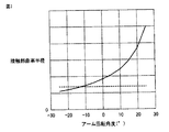
図7は、アームの回転角度と、閉側接触面の接触部の曲率半径との関係を示すグラフである。図7中の横軸は、実施の形態および比較例のアームの支軸まわりの回転角度を示す。アームが基準配置にあるときの回転角度を0とする。基準配置に対してアームが閉方向に回転するときの回転角度を正の回転角度とする。基準配置に対してアームが開方向に回転するときの回転角度を負の回転角度とする。図7中の縦軸は、アーム嵌合溝の壁面と接触する位置における、アームの嵌合部の閉側接触面の曲率半径を示す。   FIG. 7 is a graph showing the relationship between the rotation angle of the arm and the radius of curvature of the contact portion of the closed contact surface. The horizontal axis in FIG. 7 indicates the rotation angle around the support shaft of the arm of the embodiment and the comparative example. The rotation angle when the arm is in the reference arrangement is set to zero. The rotation angle when the arm rotates in the closing direction with respect to the reference arrangement is defined as a positive rotation angle. The rotation angle when the arm rotates in the opening direction with respect to the reference arrangement is defined as a negative rotation angle. The vertical axis | shaft in FIG. 7 shows the curvature radius of the close side contact surface of the fitting part of an arm in the position which contacts the wall surface of an arm fitting groove.

図7および後述する図8,9においては、実施の形態のアーム49に関するグラフを実線で示し、図6に示す比較例のアームに関するグラフを破線で示している。   In FIG. 7 and FIGS. 8 and 9 to be described later, a graph related to the arm 49 of the embodiment is shown by a solid line, and a graph related to the arm of the comparative example shown in FIG.

上述した通り、実施の形態のアーム49が閉方向に回動するにつれて、閉側接触面510の曲率が小さくなる。曲率半径は曲率の逆数であるので、図7に示すように、実施の形態のアーム49の回転角度が増大するにつれて、閉側接触面510の曲率半径が大きくなっている。これに対し、比較例のアームの閉側接触面510Zは円弧形状であるので、アームが回動しても曲率半径は変化せず、一定の値となっている。   As described above, as the arm 49 of the embodiment rotates in the closing direction, the curvature of the closing side contact surface 510 becomes smaller. Since the radius of curvature is the reciprocal of the curvature, as shown in FIG. 7, as the rotation angle of the arm 49 of the embodiment increases, the radius of curvature of the closed contact surface 510 increases. On the other hand, since the closed contact surface 510Z of the arm of the comparative example has an arc shape, even if the arm rotates, the radius of curvature does not change and is a constant value.

その結果、図7に示すアームの回転角度が最大となるとき、実施の形態の閉側接触面510の曲率半径は、比較例の閉側接触面510Zの曲率半径の2倍以上となっている。上述した通り、アームの閉方向への回転角度が増大するにつれて、アームの回動に対する抵抗が増大する。実施の形態のアーム49では、アーム49の回動に対する抵抗が増大するにつれて、閉側接触面510がより平面に近い形状となる。実施の形態のアーム49では、アーム49の閉方向への回転角度が大きくなるほど、アーム嵌合溝54の壁面に接触している閉側接触面510の面積が大きくなる。よって、実施の形態のアーム49では、閉側接触面510とアーム嵌合溝54の壁面との間に作用する圧力の増大が抑制されている。   As a result, when the rotation angle of the arm shown in FIG. 7 is maximized, the radius of curvature of the closed contact surface 510 of the embodiment is more than twice the radius of curvature of the closed contact surface 510Z of the comparative example. . As described above, as the rotation angle of the arm in the closing direction increases, the resistance to arm rotation increases. In the arm 49 according to the embodiment, as the resistance to the rotation of the arm 49 increases, the closed contact surface 510 has a shape closer to a flat surface. In the arm 49 of the embodiment, the area of the closed contact surface 510 that is in contact with the wall surface of the arm fitting groove 54 increases as the rotation angle of the arm 49 in the closing direction increases. Therefore, in the arm 49 of the embodiment, an increase in pressure acting between the closed contact surface 510 and the wall surface of the arm fitting groove 54 is suppressed.

図8は、アーム回転角度と、ユニゾンリング52の回転中心から接触部までの距離との関係を示すグラフである。図8中の横軸は、図7と同様のアームの支軸まわりの回転角度を示す。図8中の縦軸は、円環状のユニゾンリング52の中心と、アームの嵌合部の閉側接触面とアーム嵌合溝の壁面との間の接触部との間の距離を示す。   FIG. 8 is a graph showing the relationship between the arm rotation angle and the distance from the rotation center of the unison ring 52 to the contact portion. The horizontal axis in FIG. 8 shows the rotation angle around the support shaft of the arm similar to FIG. The vertical axis in FIG. 8 indicates the distance between the center of the annular unison ring 52 and the contact portion between the closed contact surface of the arm fitting portion and the wall surface of the arm fitting groove.

実施の形態のアーム49が閉方向に回動するにつれて、アーム嵌合溝54の壁面上の接触部Cは、ユニゾンリング52の径方向内側から外側へ向けて一方通行的に移動する。一方、比較例のアームが閉方向に回動するとき、アーム嵌合溝54の壁面上の接触部CZは、ユニゾンリング52の径方向に往復移動する。   As the arm 49 of the embodiment rotates in the closing direction, the contact portion C on the wall surface of the arm fitting groove 54 moves in one-way from the radially inner side to the outer side of the unison ring 52. On the other hand, when the arm of the comparative example rotates in the closing direction, the contact portion CZ on the wall surface of the arm fitting groove 54 reciprocates in the radial direction of the unison ring 52.

アームの嵌合部の閉側接触面とアーム嵌合溝の壁面とは、アームの回動に伴って摺動する。実施の形態のアーム49では、アーム嵌合溝54の壁面のうち、アーム49の閉方向への回動に伴って閉側接触面510に対して摺動する範囲が、より広い。比較例のように、アーム嵌合溝54の壁面上の接触部CZが往復移動すると、アーム嵌合溝54の壁面のより狭い範囲内で、閉側接触面に対してアーム嵌合溝54の壁面が摺動することになる。よって、実施の形態では、比較例に対して、アーム嵌合溝54の壁面上における局所的な摺動の発生が回避されている。   The close contact surface of the arm fitting portion and the wall surface of the arm fitting groove slide as the arm rotates. In the arm 49 of the embodiment, the range in which the arm sliding groove 54 slides with respect to the closing side contact surface 510 as the arm 49 rotates in the closing direction is wider. As in the comparative example, when the contact portion CZ on the wall surface of the arm fitting groove 54 is reciprocated, the arm fitting groove 54 is moved with respect to the closed contact surface within a narrower range of the wall surface of the arm fitting groove 54. The wall surface will slide. Therefore, in the embodiment, the occurrence of local sliding on the wall surface of the arm fitting groove 54 is avoided as compared with the comparative example.

図9は、アーム回転角度と、アーム嵌合溝の壁面に対する接触部の摺動距離との関係を示すグラフである。図9中の横軸は、図7と同様のアームの支軸まわりの回転角度を示す。図9中の縦軸は、アームが支軸まわりに5°回転する間に閉側接触面がアーム嵌合溝の壁面に対して摺動する距離を示す。   FIG. 9 is a graph showing the relationship between the arm rotation angle and the sliding distance of the contact portion with respect to the wall surface of the arm fitting groove. The horizontal axis in FIG. 9 shows the rotation angle around the support shaft of the arm similar to FIG. The vertical axis in FIG. 9 indicates the distance that the closed contact surface slides with respect to the wall surface of the arm fitting groove while the arm rotates 5 ° around the support shaft.

上述したように、実施の形態では、アーム49が閉方向に回動するとき、接触部Cは一方方向的に移動する。比較例では、アームが閉方向に回動するとき、接触部CZは往復移動する。実施の形態では、アーム回転角度が正の範囲において、接触部Cは、アーム嵌合溝54の壁面を径方向内側から外側へ向けて移動する。このとき、閉側接触面510上の接触部Cが接触する点は、近位縁511側から遠位縁512側へ向けて移動する。比較例では、アーム回転角度が正の範囲において、接触部CZは、アーム嵌合溝54の壁面を径方向外側から内側へ向けて移動する。このとき、閉側接触面510Z上の接触部CZが接触する点は、近位縁側から遠位縁側へ向けて移動する。   As described above, in the embodiment, when the arm 49 rotates in the closing direction, the contact portion C moves in one direction. In the comparative example, when the arm rotates in the closing direction, the contact portion CZ reciprocates. In the embodiment, in the range where the arm rotation angle is positive, the contact portion C moves the wall surface of the arm fitting groove 54 from the radially inner side to the outer side. At this time, the point where the contact portion C on the closed contact surface 510 contacts moves from the proximal edge 511 side toward the distal edge 512 side. In the comparative example, in the range where the arm rotation angle is positive, the contact portion CZ moves the wall surface of the arm fitting groove 54 from the radially outer side toward the inner side. At this time, the point where the contact portion CZ on the closed contact surface 510Z contacts moves from the proximal edge side toward the distal edge side.

実施の形態では、アーム回転角度が正の範囲において、接触部Cが閉側接触面510上を移動する向きと、接触部Cがアーム嵌合溝54の壁面上を移動する向きとが、合致している。そのため実施の形態では、アーム嵌合溝54の壁面に対する閉側接触面510の相対移動が、純転がりに近い運動になる。他方、比較例では、アーム回転角度が正の範囲において、接触部CZが閉側接触面510Z上を移動する向きと、接触部CZがアーム嵌合溝54の壁面上を移動する向きとが、相違している。その結果、実施の形態では、比較例に対して、アーム嵌合溝54の壁面に対する閉側接触面510の摺動が大幅に低減されている。   In the embodiment, the direction in which the contact portion C moves on the closed contact surface 510 and the direction in which the contact portion C moves on the wall surface of the arm fitting groove 54 in the range where the arm rotation angle is positive are the same. I'm doing it. Therefore, in the embodiment, the relative movement of the closed contact surface 510 with respect to the wall surface of the arm fitting groove 54 is a movement close to pure rolling. On the other hand, in the comparative example, when the arm rotation angle is positive, the direction in which the contact portion CZ moves on the closed contact surface 510Z and the direction in which the contact portion CZ moves on the wall surface of the arm fitting groove 54 are: It is different. As a result, in the embodiment, the sliding of the closed contact surface 510 with respect to the wall surface of the arm fitting groove 54 is significantly reduced as compared with the comparative example.

上述した説明と一部重複する部分もあるが、本実施の形態の特徴的な構成を以下、列挙する。本実施の形態のアーム49は、図2に示すように、支軸47を中心として回動可能に設けられている。ユニゾンリング52には、アーム嵌合溝54が形成されている。図3に示すように、アーム49は、閉側接触面510と開側接触面520とを有している。閉側接触面510と開側接触面520とは、アーム嵌合溝54の壁面に接触する。閉側接触面510は、支軸47から離れるにつれて、曲率が小さくなっている。   Although there are portions that partially overlap with the above description, the characteristic configurations of the present embodiment are listed below. As shown in FIG. 2, the arm 49 of the present embodiment is provided so as to be rotatable about a support shaft 47. An arm fitting groove 54 is formed in the unison ring 52. As shown in FIG. 3, the arm 49 has a closed contact surface 510 and an open contact surface 520. The closing side contact surface 510 and the opening side contact surface 520 are in contact with the wall surface of the arm fitting groove 54. The curvature of the closed contact surface 510 decreases as the distance from the support shaft 47 increases.

本実施の形態では、アーム49が閉方向に回動するとき、アーム49の回動に対する抵抗が増大するにつれて、閉側接触面510がアーム嵌合溝54の壁面に接触する面積が増大する。これにより、閉側接触面510とアーム嵌合溝54の壁面との間に作用する圧力の増大が抑制される。また、アーム49が閉方向に回動するときの、閉側接触面510に対するアーム嵌合溝54の壁面の摺動、および、アーム嵌合溝54の壁面に対する閉側接触面510の摺動が、低減されている。よって、本実施の形態では、アーム49の閉側接触面510と、閉側接触面510に接触するアーム嵌合溝54の壁面との摩耗を、ともに低減することができる。   In the present embodiment, when the arm 49 rotates in the closing direction, the area where the closed contact surface 510 contacts the wall surface of the arm fitting groove 54 increases as the resistance to the rotation of the arm 49 increases. Thereby, an increase in pressure acting between the closed contact surface 510 and the wall surface of the arm fitting groove 54 is suppressed. Further, when the arm 49 rotates in the closing direction, the sliding of the wall surface of the arm fitting groove 54 with respect to the closing side contact surface 510 and the sliding of the closing side contact surface 510 with respect to the wall surface of the arm fitting groove 54 are performed. Have been reduced. Therefore, in the present embodiment, it is possible to reduce both the wear of the closed contact surface 510 of the arm 49 and the wall surface of the arm fitting groove 54 that contacts the closed contact surface 510.

アーム49の閉側接触面510の形状を最適化することによりアーム49およびユニゾンリング52の摩耗を低減できるので、アーム49およびユニゾンリング52の摺動する表面に硬質皮膜を形成するなどの表面処理を必ずしも必要としない。これにより、表面処理に伴うコストの増加を回避でき、また、皮膜の厚みを超える摩耗発生時に急激に摩耗が進行する事態を回避することができる。   Since the wear of the arm 49 and the unison ring 52 can be reduced by optimizing the shape of the closed contact surface 510 of the arm 49, a surface treatment such as forming a hard film on the sliding surfaces of the arm 49 and the unison ring 52, etc. Is not necessarily required. Thereby, the increase in the cost accompanying a surface treatment can be avoided, and the situation where wear advances rapidly when wear exceeding the thickness of the film can be avoided.

また図3に示すように、開側接触面520は、支軸47から離れるにつれて、曲率が大きくなっている。閉側接触面510が接触するアーム嵌合溝54の閉側溝壁面と開側接触面520が接触するアーム嵌合溝54の開側溝壁面とは平行に形成されており、平行なアーム嵌合溝54の壁面に合うように、適切な開側接触面520の形状を選択することができる。   Further, as shown in FIG. 3, the open-side contact surface 520 has a curvature that increases with distance from the support shaft 47. The closed side groove wall surface of the arm fitting groove 54 that contacts the closed side contact surface 510 and the open side groove wall surface of the arm fitting groove 54 that contacts the open side contact surface 520 are formed in parallel, and the parallel arm fitting grooves An appropriate shape of the open-side contact surface 520 can be selected to fit the wall surface of 54.

また図3に示すように、閉側接触面510は、支軸47から離れるにつれて曲率が連続的に小さくなっている。閉側接触面510を滑らかな曲面形状に形成することで、閉側接触面510とアーム嵌合溝54の壁面との接触面積が局所的に急増することを回避できるので、アーム49およびアーム嵌合溝54の摩耗を確実に低減することができる。   Further, as shown in FIG. 3, the curvature of the closed contact surface 510 continuously decreases as the distance from the support shaft 47 increases. By forming the closed-side contact surface 510 in a smooth curved surface shape, it is possible to avoid a local sudden increase in the contact area between the closed-side contact surface 510 and the wall surface of the arm fitting groove 54. Wear of the joint groove 54 can be reliably reduced.

なお、図3を参照して説明したアーム49では、閉側接触面510と開側接触面520とは、平面状の内側表面530および外側表面540を介してつながっている。アームの嵌合部には、平面状の内側表面および外側表面が形成されなくてもよく、閉側接触面と開側接触面とが連続して形成されていてもよい。   In the arm 49 described with reference to FIG. 3, the closed contact surface 510 and the open contact surface 520 are connected via the planar inner surface 530 and the outer surface 540. In the fitting portion of the arm, the planar inner surface and the outer surface may not be formed, and the closed side contact surface and the open side contact surface may be continuously formed.

実施の形態では、閉側接触面510の形状を最適化しているが、開側接触面520を同様の形状としてもよい。この場合、上述した閉側接触面510と同様に、アーム嵌合溝54の壁面との摩耗を低減できる作用効果が奏される。   In the embodiment, the shape of the closed contact surface 510 is optimized, but the open contact surface 520 may have the same shape. In this case, similarly to the above-described closed-side contact surface 510, there is an effect that the wear with the wall surface of the arm fitting groove 54 can be reduced.

以上のように本発明の実施の形態について説明を行なったが、今回開示された実施の形態はすべての点で例示であって、制限的なものではないと考えられるべきである。この発明の範囲は上記した説明ではなくて特許請求の範囲によって示され、特許請求の範囲と均等の意味、および範囲内でのすべての変更が含まれることが意図される。   Although the embodiment of the present invention has been described as above, the embodiment disclosed this time should be considered as illustrative in all points and not restrictive. The scope of the present invention is defined by the terms of the claims, rather than the description above, and is intended to include any modifications within the scope and meaning equivalent to the terms of the claims.

10 可変ノズルターボチャージャ、12 ロータハウジング、14 タービンハウジング、15 排気出口、19 側壁部、20 ロータ、22 タービンホイール、23 タービンブレード、24 ロータシャフト、26 コンプレッサホイール、27 インペラ、30 スクロール通路、31 ノズル通路、36 可変ノズル機構、38 ノズルリング、41 環状空間部、46 可変ノズル、47,57 支軸、48 ノズルベーン、49 アーム、50,61 嵌合部、52 ユニゾンリング、54,54A,54B,54C,63 アーム嵌合溝、56 駆動部材、58 駆動レバー、60 駆動アーム、65 アクチュエータ、67 コントローラ、68 作動量検出手段、510,510Z 閉側接触面、511,521 近位縁、512,522 遠位縁、520 開側接触面、530 内側表面、540 外側表面、C,CZ 接触部、Y1,Y2 矢印。   DESCRIPTION OF SYMBOLS 10 Variable nozzle turbocharger, 12 Rotor housing, 14 Turbine housing, 15 Exhaust outlet, 19 Side wall part, 20 Rotor, 22 Turbine wheel, 23 Turbine blade, 24 Rotor shaft, 26 Compressor wheel, 27 Impeller, 30 Scroll path, 31 Nozzle Passage, 36 Variable nozzle mechanism, 38 Nozzle ring, 41 Annular space, 46 Variable nozzle, 47, 57 Support shaft, 48 Nozzle vane, 49 Arm, 50, 61 Fitting, 52 Unison ring, 54, 54A, 54B, 54C , 63 Arm fitting groove, 56 Drive member, 58 Drive lever, 60 Drive arm, 65 Actuator, 67 Controller, 68 Actuation amount detection means, 510, 510Z Closed contact surface, 511, 521 Proximal edge, 512, 52 Distal edge, 520 open side contact surface 530 inner surface 540 outer surface, C, CZ contact portion, Y1, Y2 arrows.

Claims (4)

ターボチャージャに用いられ、ノズル通路を介してタービンブレードに吹き付けられる排気ガスを変動させる、可変ノズル機構であって、
前記ノズル通路に設けられた複数のノズルベーンと、
各々が軸支端と自由端とを有し、前記軸支端は支軸によって前記ノズルベーンに一体に連結される、複数のアームと、
複数の溝が形成され、前記溝の各々に前記アームの前記自由端がそれぞれ係合する、ユニゾンリングとを備え、
前記アームと前記ノズルベーンとは、前記ノズル通路の断面積を増大する開方向と減少する閉方向との両方に前記ユニゾンリングが回転するとき、前記支軸を中心に一体に開方向と閉方向とに回転して、前記ノズル通路の断面積を変動可能であり、
前記アームの前記自由端は、該アームの閉方向回転側と開方向回転側との一対の接触面を有し、前記一対の接触面の各々が前記ユニゾンリングの前記溝を形成する一対の壁の一方にそれぞれ接触し、
前記アームの前記接触面の一方は、前記ユニゾンリングの前記溝の壁面に向けた凸曲面をなすとともに、該凸曲面の前記支軸に近い側と前記支軸から遠い側との曲率が異なる、可変ノズル機構。
A variable nozzle mechanism that is used in a turbocharger and varies exhaust gas blown to a turbine blade through a nozzle passage,
A plurality of nozzle vanes provided in the nozzle passage;
A plurality of arms each having a pivot end and a free end, the pivot end integrally coupled to the nozzle vane by a pivot;
A plurality of grooves, each having a unison ring with which each of the free ends of the arms engages,
When the unison ring rotates in both an opening direction in which a cross-sectional area of the nozzle passage increases and a closing direction in which the arm and the nozzle vane rotate, the opening direction and the closing direction are integrally formed around the support shaft. And the cross-sectional area of the nozzle passage can be varied.
The free end of the arm has a pair of contact surfaces of a close direction rotation side and an open direction rotation side of the arm, and each of the pair of contact surfaces forms a groove of the unison ring. Each one of the
One of the contact surfaces of the arm forms a convex curved surface toward the wall surface of the groove of the unison ring, and the curvature of the side of the convex curved surface near the support shaft and the side far from the support shaft are different. Variable nozzle mechanism.
前記排気ガスの圧力は前記ノズル通路を減少させる閉方向に前記ノズルベーンに作用し、前記アームの前記曲率を有する前記接触面は、前記アームの回動の閉方向側に位置するとともに、前記曲率は前記支軸から離れるにつれて小さくなる、請求項1に記載の可変ノズル機構。   The pressure of the exhaust gas acts on the nozzle vane in the closing direction to reduce the nozzle passage, the contact surface having the curvature of the arm is located on the closing direction side of the rotation of the arm, and the curvature is The variable nozzle mechanism according to claim 1, wherein the variable nozzle mechanism decreases as the distance from the support shaft increases. 前記排気ガスの圧力は前記ノズル通路を増大させる開方向に前記ノズルベーンに作用し、前記アームの前記曲率を有する前記接触面は、前記アームの回動の開方向側に位置するとともに、前記曲率は前記支軸から離れるにつれて大きくなる、請求項1に記載の可変ノズル機構。   The pressure of the exhaust gas acts on the nozzle vane in the opening direction that increases the nozzle passage, the contact surface having the curvature of the arm is located on the opening direction side of the rotation of the arm, and the curvature is The variable nozzle mechanism according to claim 1, wherein the variable nozzle mechanism increases as the distance from the support shaft increases. 前記アームの前記接触面の前記曲率は、前記支軸から離れるにつれて連続的に変化する、請求項1乃至3のいずれか1項に記載の可変ノズル機構。   The variable nozzle mechanism according to any one of claims 1 to 3, wherein the curvature of the contact surface of the arm continuously changes as the arm moves away from the support shaft.
JP2017057526A 2016-03-28 2017-03-23 Variable nozzle mechanism Active JP6597689B2 (en)

Priority Applications (2)

Application Number Priority Date Filing Date Title
US15/469,632 US10563536B2 (en) 2016-03-28 2017-03-27 Variable nozzle mechanism used for turbocharger
EP17163078.3A EP3225787B1 (en) 2016-03-28 2017-03-27 Turbocharger with variable nozzle mechanism

Applications Claiming Priority (2)

Application Number Priority Date Filing Date Title
JP2016064341 2016-03-28

Publications (2)

Publication Number Publication Date
JP2017180462A true JP2017180462A (en) 2017-10-05
JP6597689B2 JP6597689B2 (en) 2019-10-30

Family

ID=59983812

Family Applications (1)

Application Number Title Priority Date Filing Date
JP2017057526A Active JP6597689B2 (en) 2016-03-28 2017-03-23 Variable nozzle mechanism

Country Status (2)

Country Link
JP (1) JP6597689B2 (en)
CN (1) CN107237654B (en)

Cited By (4)

* Cited by examiner, † Cited by third party
Publication number Priority date Publication date Assignee Title
WO2019069678A1 (en) * 2017-10-06 2019-04-11 株式会社Ihi Variable geometry mechanism
JPWO2020225898A1 (en) * 2019-05-09 2020-11-12
DE112019007259T5 (en) 2019-06-26 2022-01-20 Mitsubishi Heavy Industries Engine & Turbocharger, Ltd. VARIABLE NOZZLE DEVICE AND VARIABLE DISPLACEMENT TURBOCHARGER
CN114961884A (en) * 2022-04-27 2022-08-30 萍乡德博科技股份有限公司 Blade assembly of gasoline engine turbocharging variable cross section nozzle ring, nozzle ring

Families Citing this family (2)

* Cited by examiner, † Cited by third party
Publication number Priority date Publication date Assignee Title
CN108506051A (en) * 2018-04-19 2018-09-07 萍乡德博科技股份有限公司 Pressure booster with variable cross section nozzle ring
CN112324569A (en) * 2020-09-17 2021-02-05 杭州萧山技师学院 Turbine disc with self-lubricating structure for miniature gas turbine

Citations (9)

* Cited by examiner, † Cited by third party
Publication number Priority date Publication date Assignee Title
JPS49113973A (en) * 1973-02-19 1974-10-30
JPS5970035U (en) * 1982-10-30 1984-05-12 いすゞ自動車株式会社 Variable displacement turbocharger nozzle vane drive device
DE102004043928A1 (en) * 2004-09-11 2006-04-13 Ihi Charging Systems International Gmbh Vane adjusting drive especially for exhaust powered turbocharger has a control ring linked to a support mounting using pivot mounted support arms with shaped outer ends
JP2009243300A (en) * 2008-03-28 2009-10-22 Ihi Corp Variable nozzle unit and variable capacity type turbocharger
WO2010089879A1 (en) * 2009-02-06 2010-08-12 トヨタ自動車株式会社 Variable capacity supercharger for internal combustion engine
US20110138805A1 (en) * 2009-12-15 2011-06-16 Honeywell International Inc. Conjugate curve profiles for vane arms, main-arms, and unison rings
WO2013129407A1 (en) * 2012-02-29 2013-09-06 三菱重工業株式会社 Variable-capacity turbocharger
DE102012218138A1 (en) * 2012-10-04 2014-04-10 Bosch Mahle Turbo Systems Gmbh & Co. Kg Supercharger for motor vehicle, has adjusting element formed as thin sheet component that is arranged on turbine wheel at opposite side of blade bearing ring in which several guide vanes are rotatably mounted
US20140341719A1 (en) * 2013-05-16 2014-11-20 Toyota Jidosha Kabushiki Kaisha Variable nozzle turbochargers

Family Cites Families (4)

* Cited by examiner, † Cited by third party
Publication number Priority date Publication date Assignee Title
US4659295A (en) * 1984-04-20 1987-04-21 The Garrett Corporation Gas seal vanes of variable nozzle turbine
KR101031633B1 (en) * 2009-04-17 2011-04-27 (주)계양정밀 Nozzle Assembly of Variable Geometry Turbocharger and Method of Manufacture Thereof
KR101144515B1 (en) * 2009-10-27 2012-05-11 현대자동차주식회사 Nozzle Assembly of Variable Geometry Turbocharger
KR101915092B1 (en) * 2012-04-27 2018-11-06 보르그워너 인코퍼레이티드 Exhaust-gas turbocharger

Patent Citations (12)

* Cited by examiner, † Cited by third party
Publication number Priority date Publication date Assignee Title
JPS49113973A (en) * 1973-02-19 1974-10-30
JPS5970035U (en) * 1982-10-30 1984-05-12 いすゞ自動車株式会社 Variable displacement turbocharger nozzle vane drive device
DE102004043928A1 (en) * 2004-09-11 2006-04-13 Ihi Charging Systems International Gmbh Vane adjusting drive especially for exhaust powered turbocharger has a control ring linked to a support mounting using pivot mounted support arms with shaped outer ends
JP2009243300A (en) * 2008-03-28 2009-10-22 Ihi Corp Variable nozzle unit and variable capacity type turbocharger
WO2010089879A1 (en) * 2009-02-06 2010-08-12 トヨタ自動車株式会社 Variable capacity supercharger for internal combustion engine
US20120023938A1 (en) * 2009-02-06 2012-02-02 Toyota Jidosha Kabushiki Kaisha Variable capacity supercharger for internal combustion engine
US20110138805A1 (en) * 2009-12-15 2011-06-16 Honeywell International Inc. Conjugate curve profiles for vane arms, main-arms, and unison rings
WO2013129407A1 (en) * 2012-02-29 2013-09-06 三菱重工業株式会社 Variable-capacity turbocharger
US20150104296A1 (en) * 2012-02-29 2015-04-16 Mitsubishi Heavy Industries, Ltd. Variable geometry turbocharger
DE102012218138A1 (en) * 2012-10-04 2014-04-10 Bosch Mahle Turbo Systems Gmbh & Co. Kg Supercharger for motor vehicle, has adjusting element formed as thin sheet component that is arranged on turbine wheel at opposite side of blade bearing ring in which several guide vanes are rotatably mounted
US20140341719A1 (en) * 2013-05-16 2014-11-20 Toyota Jidosha Kabushiki Kaisha Variable nozzle turbochargers
JP2014224498A (en) * 2013-05-16 2014-12-04 株式会社豊田自動織機 Variable nozzle turbocharger

Cited By (8)

* Cited by examiner, † Cited by third party
Publication number Priority date Publication date Assignee Title
WO2019069678A1 (en) * 2017-10-06 2019-04-11 株式会社Ihi Variable geometry mechanism
JPWO2020225898A1 (en) * 2019-05-09 2020-11-12
WO2020225898A1 (en) * 2019-05-09 2020-11-12 三菱重工エンジン&ターボチャージャ株式会社 Variable capacity type exhaust turbo-supercharger
JP7217345B2 (en) 2019-05-09 2023-02-02 三菱重工エンジン&ターボチャージャ株式会社 Variable displacement exhaust turbocharger
DE112019007259T5 (en) 2019-06-26 2022-01-20 Mitsubishi Heavy Industries Engine & Turbocharger, Ltd. VARIABLE NOZZLE DEVICE AND VARIABLE DISPLACEMENT TURBOCHARGER
US11739655B2 (en) 2019-06-26 2023-08-29 Mitsubishi Heavy Industries Engine & Turbocharger, Ltd. Variable nozzle device and variable-displacement type exhaust turbocharger
CN114961884A (en) * 2022-04-27 2022-08-30 萍乡德博科技股份有限公司 Blade assembly of gasoline engine turbocharging variable cross section nozzle ring, nozzle ring
CN114961884B (en) * 2022-04-27 2024-04-05 萍乡德博科技股份有限公司 Vane assembly of petrol engine turbocharging variable-section nozzle ring and nozzle ring

Also Published As

Publication number Publication date
CN107237654B (en) 2019-04-16
JP6597689B2 (en) 2019-10-30
CN107237654A (en) 2017-10-10

Similar Documents

Publication Publication Date Title
JP6597689B2 (en) Variable nozzle mechanism
JP5836317B2 (en) Variable nozzle turbocharger
US9903379B2 (en) Variable nozzle unit and variable geometry system turbocharger
JP5915146B2 (en) Variable nozzle unit and variable capacity turbocharger
JP2013130116A (en) Variable nozzle unit and variable capacity type supercharger
JP6690730B2 (en) Variable nozzle unit and supercharger
JP6617837B2 (en) Variable nozzle unit and turbocharger
JP4779750B2 (en) Centrifugal compressor with variable diffuser
US10563536B2 (en) Variable nozzle mechanism used for turbocharger
WO2016071712A1 (en) Compressor and turbocharger
JP5446969B2 (en) Compressor
US20200040761A1 (en) Variable-geometry turbocharger
JP2012097662A (en) Variable diffuser of centrifugal compressor for supercharger
JP6424968B2 (en) Flow variable valve mechanism and supercharger
JP2011169192A (en) Variable diffuser of centrifugal compressor for supercharger
JP6459881B2 (en) Variable nozzle turbocharger
JPH01208501A (en) Variable capacity turbine
JP2007255220A (en) Centrifugal compressor with variable diffuser
WO2019069678A1 (en) Variable geometry mechanism
JP6115179B2 (en) Variable nozzle unit and variable capacity turbocharger
JP7155429B2 (en) Variable nozzle device and variable capacity exhaust turbocharger
JP6963120B2 (en) Nozzle vane
JP2011169193A (en) Variable diffuser of centrifugal compressor for supercharger
WO2020188763A1 (en) Centrifugal compressor and turbocharger
CN114623088A (en) Rotary machine

Legal Events

Date Code Title Description
A621 Written request for application examination

Free format text: JAPANESE INTERMEDIATE CODE: A621

Effective date: 20181005

A977 Report on retrieval

Free format text: JAPANESE INTERMEDIATE CODE: A971007

Effective date: 20190617

A131 Notification of reasons for refusal

Free format text: JAPANESE INTERMEDIATE CODE: A131

Effective date: 20190625

A521 Request for written amendment filed

Free format text: JAPANESE INTERMEDIATE CODE: A523

Effective date: 20190820

TRDD Decision of grant or rejection written
A01 Written decision to grant a patent or to grant a registration (utility model)

Free format text: JAPANESE INTERMEDIATE CODE: A01

Effective date: 20190903

A61 First payment of annual fees (during grant procedure)

Free format text: JAPANESE INTERMEDIATE CODE: A61

Effective date: 20190916

R151 Written notification of patent or utility model registration

Ref document number: 6597689

Country of ref document: JP

Free format text: JAPANESE INTERMEDIATE CODE: R151