JP2017180325A - Internal combustion engine with supercharger of saddle-riding type vehicle - Google Patents
Internal combustion engine with supercharger of saddle-riding type vehicle Download PDFInfo
- Publication number
- JP2017180325A JP2017180325A JP2016069445A JP2016069445A JP2017180325A JP 2017180325 A JP2017180325 A JP 2017180325A JP 2016069445 A JP2016069445 A JP 2016069445A JP 2016069445 A JP2016069445 A JP 2016069445A JP 2017180325 A JP2017180325 A JP 2017180325A
- Authority
- JP
- Japan
- Prior art keywords
- supercharger
- internal combustion
- combustion engine
- crankcase
- saddle
- Prior art date
- Legal status (The legal status is an assumption and is not a legal conclusion. Google has not performed a legal analysis and makes no representation as to the accuracy of the status listed.)
- Granted
Links
Images


Classifications
-
- F—MECHANICAL ENGINEERING; LIGHTING; HEATING; WEAPONS; BLASTING
- F02—COMBUSTION ENGINES; HOT-GAS OR COMBUSTION-PRODUCT ENGINE PLANTS
- F02D—CONTROLLING COMBUSTION ENGINES
- F02D41/00—Electrical control of supply of combustible mixture or its constituents
- F02D41/0002—Controlling intake air
- F02D41/0007—Controlling intake air for control of turbo-charged or super-charged engines
-
- B—PERFORMING OPERATIONS; TRANSPORTING
- B60—VEHICLES IN GENERAL
- B60K—ARRANGEMENT OR MOUNTING OF PROPULSION UNITS OR OF TRANSMISSIONS IN VEHICLES; ARRANGEMENT OR MOUNTING OF PLURAL DIVERSE PRIME-MOVERS IN VEHICLES; AUXILIARY DRIVES FOR VEHICLES; INSTRUMENTATION OR DASHBOARDS FOR VEHICLES; ARRANGEMENTS IN CONNECTION WITH COOLING, AIR INTAKE, GAS EXHAUST OR FUEL SUPPLY OF PROPULSION UNITS IN VEHICLES
- B60K13/00—Arrangement in connection with combustion air intake or gas exhaust of propulsion units
- B60K13/02—Arrangement in connection with combustion air intake or gas exhaust of propulsion units concerning intake
-
- B—PERFORMING OPERATIONS; TRANSPORTING
- B62—LAND VEHICLES FOR TRAVELLING OTHERWISE THAN ON RAILS
- B62K—CYCLES; CYCLE FRAMES; CYCLE STEERING DEVICES; RIDER-OPERATED TERMINAL CONTROLS SPECIALLY ADAPTED FOR CYCLES; CYCLE AXLE SUSPENSIONS; CYCLE SIDE-CARS, FORECARS, OR THE LIKE
- B62K11/00—Motorcycles, engine-assisted cycles or motor scooters with one or two wheels
- B62K11/02—Frames
- B62K11/04—Frames characterised by the engine being between front and rear wheels
-
- F—MECHANICAL ENGINEERING; LIGHTING; HEATING; WEAPONS; BLASTING
- F02—COMBUSTION ENGINES; HOT-GAS OR COMBUSTION-PRODUCT ENGINE PLANTS
- F02B—INTERNAL-COMBUSTION PISTON ENGINES; COMBUSTION ENGINES IN GENERAL
- F02B33/00—Engines characterised by provision of pumps for charging or scavenging
- F02B33/32—Engines with pumps other than of reciprocating-piston type
- F02B33/34—Engines with pumps other than of reciprocating-piston type with rotary pumps
- F02B33/40—Engines with pumps other than of reciprocating-piston type with rotary pumps of non-positive-displacement type
-
- F—MECHANICAL ENGINEERING; LIGHTING; HEATING; WEAPONS; BLASTING
- F02—COMBUSTION ENGINES; HOT-GAS OR COMBUSTION-PRODUCT ENGINE PLANTS
- F02B—INTERNAL-COMBUSTION PISTON ENGINES; COMBUSTION ENGINES IN GENERAL
- F02B39/00—Component parts, details, or accessories relating to, driven charging or scavenging pumps, not provided for in groups F02B33/00 - F02B37/00
- F02B39/02—Drives of pumps; Varying pump drive gear ratio
- F02B39/04—Mechanical drives; Variable-gear-ratio drives
- F02B39/06—Mechanical drives; Variable-gear-ratio drives the engine torque being divided by a differential gear for driving a pump and the engine output shaft
-
- F—MECHANICAL ENGINEERING; LIGHTING; HEATING; WEAPONS; BLASTING
- F02—COMBUSTION ENGINES; HOT-GAS OR COMBUSTION-PRODUCT ENGINE PLANTS
- F02B—INTERNAL-COMBUSTION PISTON ENGINES; COMBUSTION ENGINES IN GENERAL
- F02B61/00—Adaptations of engines for driving vehicles or for driving propellers; Combinations of engines with gearing
- F02B61/02—Adaptations of engines for driving vehicles or for driving propellers; Combinations of engines with gearing for driving cycles
-
- F—MECHANICAL ENGINEERING; LIGHTING; HEATING; WEAPONS; BLASTING
- F02—COMBUSTION ENGINES; HOT-GAS OR COMBUSTION-PRODUCT ENGINE PLANTS
- F02B—INTERNAL-COMBUSTION PISTON ENGINES; COMBUSTION ENGINES IN GENERAL
- F02B75/00—Other engines
- F02B75/16—Engines characterised by number of cylinders, e.g. single-cylinder engines
- F02B75/18—Multi-cylinder engines
- F02B75/22—Multi-cylinder engines with cylinders in V, fan, or star arrangement
-
- F—MECHANICAL ENGINEERING; LIGHTING; HEATING; WEAPONS; BLASTING
- F02—COMBUSTION ENGINES; HOT-GAS OR COMBUSTION-PRODUCT ENGINE PLANTS
- F02D—CONTROLLING COMBUSTION ENGINES
- F02D11/00—Arrangements for, or adaptations to, non-automatic engine control initiation means, e.g. operator initiated
- F02D11/06—Arrangements for, or adaptations to, non-automatic engine control initiation means, e.g. operator initiated characterised by non-mechanical control linkages, e.g. fluid control linkages or by control linkages with power drive or assistance
- F02D11/10—Arrangements for, or adaptations to, non-automatic engine control initiation means, e.g. operator initiated characterised by non-mechanical control linkages, e.g. fluid control linkages or by control linkages with power drive or assistance of the electric type
-
- F—MECHANICAL ENGINEERING; LIGHTING; HEATING; WEAPONS; BLASTING
- F02—COMBUSTION ENGINES; HOT-GAS OR COMBUSTION-PRODUCT ENGINE PLANTS
- F02D—CONTROLLING COMBUSTION ENGINES
- F02D9/00—Controlling engines by throttling air or fuel-and-air induction conduits or exhaust conduits
- F02D9/08—Throttle valves specially adapted therefor; Arrangements of such valves in conduits
- F02D9/10—Throttle valves specially adapted therefor; Arrangements of such valves in conduits having pivotally-mounted flaps
- F02D9/1035—Details of the valve housing
- F02D9/1055—Details of the valve housing having a fluid by-pass
-
- F—MECHANICAL ENGINEERING; LIGHTING; HEATING; WEAPONS; BLASTING
- F02—COMBUSTION ENGINES; HOT-GAS OR COMBUSTION-PRODUCT ENGINE PLANTS
- F02M—SUPPLYING COMBUSTION ENGINES IN GENERAL WITH COMBUSTIBLE MIXTURES OR CONSTITUENTS THEREOF
- F02M35/00—Combustion-air cleaners, air intakes, intake silencers, or induction systems specially adapted for, or arranged on, internal-combustion engines
- F02M35/10—Air intakes; Induction systems
- F02M35/1015—Air intakes; Induction systems characterised by the engine type
- F02M35/10157—Supercharged engines
-
- F—MECHANICAL ENGINEERING; LIGHTING; HEATING; WEAPONS; BLASTING
- F02—COMBUSTION ENGINES; HOT-GAS OR COMBUSTION-PRODUCT ENGINE PLANTS
- F02M—SUPPLYING COMBUSTION ENGINES IN GENERAL WITH COMBUSTIBLE MIXTURES OR CONSTITUENTS THEREOF
- F02M35/00—Combustion-air cleaners, air intakes, intake silencers, or induction systems specially adapted for, or arranged on, internal-combustion engines
- F02M35/10—Air intakes; Induction systems
- F02M35/104—Intake manifolds
- F02M35/116—Intake manifolds for engines with cylinders in V-arrangement or arranged oppositely relative to the main shaft
-
- F—MECHANICAL ENGINEERING; LIGHTING; HEATING; WEAPONS; BLASTING
- F02—COMBUSTION ENGINES; HOT-GAS OR COMBUSTION-PRODUCT ENGINE PLANTS
- F02M—SUPPLYING COMBUSTION ENGINES IN GENERAL WITH COMBUSTIBLE MIXTURES OR CONSTITUENTS THEREOF
- F02M35/00—Combustion-air cleaners, air intakes, intake silencers, or induction systems specially adapted for, or arranged on, internal-combustion engines
- F02M35/16—Combustion-air cleaners, air intakes, intake silencers, or induction systems specially adapted for, or arranged on, internal-combustion engines characterised by use in vehicles
- F02M35/162—Motorcycles; All-terrain vehicles, e.g. quads, snowmobiles; Small vehicles, e.g. forklifts
-
- F—MECHANICAL ENGINEERING; LIGHTING; HEATING; WEAPONS; BLASTING
- F02—COMBUSTION ENGINES; HOT-GAS OR COMBUSTION-PRODUCT ENGINE PLANTS
- F02F—CYLINDERS, PISTONS OR CASINGS, FOR COMBUSTION ENGINES; ARRANGEMENTS OF SEALINGS IN COMBUSTION ENGINES
- F02F7/00—Casings, e.g. crankcases or frames
- F02F7/0065—Shape of casings for other machine parts and purposes, e.g. utilisation purposes, safety
- F02F7/0073—Adaptations for fitting the engine, e.g. front-plates or bell-housings
- F02F2007/0075—Front covers
-
- F—MECHANICAL ENGINEERING; LIGHTING; HEATING; WEAPONS; BLASTING
- F02—COMBUSTION ENGINES; HOT-GAS OR COMBUSTION-PRODUCT ENGINE PLANTS
- F02F—CYLINDERS, PISTONS OR CASINGS, FOR COMBUSTION ENGINES; ARRANGEMENTS OF SEALINGS IN COMBUSTION ENGINES
- F02F7/00—Casings, e.g. crankcases or frames
- F02F7/0065—Shape of casings for other machine parts and purposes, e.g. utilisation purposes, safety
- F02F7/0068—Adaptations for other accessories
-
- Y—GENERAL TAGGING OF NEW TECHNOLOGICAL DEVELOPMENTS; GENERAL TAGGING OF CROSS-SECTIONAL TECHNOLOGIES SPANNING OVER SEVERAL SECTIONS OF THE IPC; TECHNICAL SUBJECTS COVERED BY FORMER USPC CROSS-REFERENCE ART COLLECTIONS [XRACs] AND DIGESTS
- Y02—TECHNOLOGIES OR APPLICATIONS FOR MITIGATION OR ADAPTATION AGAINST CLIMATE CHANGE
- Y02T—CLIMATE CHANGE MITIGATION TECHNOLOGIES RELATED TO TRANSPORTATION
- Y02T10/00—Road transport of goods or passengers
- Y02T10/10—Internal combustion engine [ICE] based vehicles
- Y02T10/12—Improving ICE efficiencies
Abstract
Description
本発明は、鞍乗り型車両の過給機付き内燃機関に関する。 The present invention relates to an internal combustion engine with a supercharger for a saddle-ride type vehicle.
従来、鞍乗り型車両の過給機付き内燃機関において、シリンダヘッド後方でクランクケース後部の位置に過給機を配置したものが知られている(例えば、特許文献1参照)。 2. Description of the Related Art Conventionally, an internal combustion engine with a supercharger for a saddle-ride type vehicle is known in which a supercharger is disposed at a rear portion of a crankcase behind a cylinder head (see, for example, Patent Document 1).
上記特許文献1では、過給機の位置が、車体スペースの限られた鞍乗り型車両においては車体スペースを考慮した最適位置の一つであると考えられるものの、シリンダヘッドの下方に位置するクランクケースの後部以外に配置に適する箇所が見当たらず、レイアウトの設計自由度が少ない。
このような過給機の配置構造では、クランクケースの上方に内燃機関の補機部品としての吸気チャンバが配置されているために、補機部品の組付け前にクランクケース上方から過給機の組付けを行う必要があり、組付性や生産性が制約されていた。そこで、自動車と比べて車体スペースが限られた鞍乗り型車両であっても、組付性及び生産性を考慮した過給機付き内燃機関が求められている。
本発明の目的は、組付性及び生産性の向上を図ることが可能な鞍乗り型車両の過給機付き内燃機関を提供することにある。
In Patent Document 1, although the position of the supercharger is considered to be one of the optimum positions in consideration of the vehicle body space in a saddle-ride type vehicle with a limited vehicle body space, the crank located below the cylinder head There is no place suitable for arrangement other than the rear part of the case, and there is little freedom in layout design.
In such a supercharger arrangement structure, since the intake chamber as an auxiliary machine part of the internal combustion engine is arranged above the crankcase, the supercharger is installed from above the crankcase before assembling the auxiliary machine parts. Assembling was necessary, and assembling and productivity were limited. Therefore, there is a demand for an internal combustion engine with a supercharger that takes into consideration assembly and productivity even in a saddle-ride type vehicle that has a limited body space compared to an automobile.
An object of the present invention is to provide an internal combustion engine with a supercharger for a saddle-ride type vehicle capable of improving assemblability and productivity.
上述した課題を解決するため、本発明は、シリンダヘッド(92,97)よりも下方に位置するクランクケース(81)の上方に過給機(63)が配置された鞍乗り型車両の過給機付き内燃機関において、前記クランクケース(81)は、車幅方向外側からケースカバー(116)に覆われ、前記過給機(63)は、前記ケースカバー(116)によって支持されることを特徴とする。 In order to solve the above-described problem, the present invention provides a supercharging of a saddle-ride type vehicle in which a supercharger (63) is disposed above a crankcase (81) positioned below a cylinder head (92, 97). In the internal combustion engine with a machine, the crankcase (81) is covered with a case cover (116) from the outside in the vehicle width direction, and the supercharger (63) is supported by the case cover (116). And
上記構成において、前記過給機(63)は、前記クランクケース(81)に収容されるクランク軸(82)から動力伝達部(83)を介して動力が伝達され、前記ケースカバー(116)は、前記動力伝達部(83)を覆う動力伝達部カバーであっても良い。
また、上記構成において、燃料をシリンダブロック(91,96)に設けられたシリンダ(91a,96a)内に直接噴射する直噴式であって、燃料噴射用の高圧燃料ポンプ(117)が、前記ケースカバー(116)に取付けられるとともに側面視で前記シリンダブロック(96)と重なるように配置されるようにしても良い。
In the above configuration, the supercharger (63) receives power from the crankshaft (82) accommodated in the crankcase (81) via the power transmission unit (83), and the case cover (116) A power transmission part cover covering the power transmission part (83) may be used.
Further, in the above configuration, the fuel is directly injected into the cylinders (91a, 96a) provided in the cylinder block (91, 96), and the high pressure fuel pump (117) for fuel injection includes the case. You may make it arrange | position so that it may attach to a cover (116) and may overlap with the said cylinder block (96) by side view.
また、上記構成において、前記クランクケース(81)に駆動軸(103)が回転可能に支持され、前記駆動軸(103)に、前記高圧燃料ポンプ(117)を駆動するカムロブ(103a)が形成され、前記クランク軸(82)に設けられた駆動ギヤ(118)と、前記駆動軸(103)に設けられた従動ギヤ(109)とが噛み合うことで前記クランク軸(82)の回転が前記駆動軸(103)に伝達されるようにしても良い。 In the above configuration, the drive shaft (103) is rotatably supported by the crankcase (81), and a cam lobe (103a) for driving the high-pressure fuel pump (117) is formed on the drive shaft (103). The drive gear (118) provided on the crankshaft (82) and the driven gear (109) provided on the drive shaft (103) mesh with each other, so that the rotation of the crankshaft (82) is caused by the drive shaft. (103) may be transmitted.
また、上記構成において、前記シリンダヘッド(92)の上方にエアクリーナケース(158)が配置され、前記エアクリーナケース(158)と前記シリンダヘッド(92)との間に、前記過給機(63)の過給圧を調整するバイパスバルブ装置(138)と、スロットル信号に応じてアクチュエータ(132a)にてスロットルバルブ(132b)を開閉するTBW用スロットル装置(132)とが配置されるようにしても良い。 In the above configuration, an air cleaner case (158) is disposed above the cylinder head (92), and the supercharger (63) is disposed between the air cleaner case (158) and the cylinder head (92). A bypass valve device (138) that adjusts the supercharging pressure and a TBW throttle device (132) that opens and closes the throttle valve (132b) by an actuator (132a) according to a throttle signal may be arranged. .
また、上記構成において、前記バイパスバルブ装置(138)と前記TBW用スロットル装置(132)とが、側面視で重なるようにしても良い。
また、上記構成において、前バンク(31A)と後バンク(31B)とを備えるV型であって、前記過給機(63)が、前記前バンク(31A)と前記後バンク(31B)との間に配置されるようにしても良い。
In the above configuration, the bypass valve device (138) and the TBW throttle device (132) may overlap in a side view.
Further, in the above configuration, the V-type including a front bank (31A) and a rear bank (31B), wherein the supercharger (63) includes a front bank (31A) and a rear bank (31B). You may make it arrange | position between.
また、上記構成において、前記前バンク(31A)及び前記後バンク(31B)の一方に前記TBW用スロットル装置(132)が設けられ、前記前バンク(31A)及び前記後バンク(31B)の他方にスロットル装置(133)が設けられ、前記TBW用スロットル装置(132)及び前記スロットル装置(133)にそれぞれ備えるスロットルバルブ(132b,133b)が連結部材(144)によって連動可能とされ、前記連結部材(144)は、前記過給機(63)に接続される配管(136)の車幅方向内側に配置されるようにしても良い。 In the above configuration, the TBW throttle device (132) is provided in one of the front bank (31A) and the rear bank (31B), and the other of the front bank (31A) and the rear bank (31B). A throttle device (133) is provided, and the throttle valve (132b, 133b) provided in the TBW throttle device (132) and the throttle device (133) can be interlocked by a connecting member (144), and the connecting member ( 144) may be arranged on the inner side in the vehicle width direction of the pipe (136) connected to the supercharger (63).
また、上記構成において、前記ケースカバー(116)は、前記クランクケース(81)の側方を覆うクランクケースカバー部(116e)と、前記クランクケースカバー部(116e)よりも車幅方向外側に突出して前記動力伝達部(83)に含まれるギヤ(145,146,147)を収容するギヤ収容部(116b)とを備え、前記高圧燃料ポンプ(117)は、前記クランクケースカバー部(116e)の車幅方向外方に配置されるとともに前記ギヤ収容部(116e)の後部に取付けられるようにしても良い。 In the above configuration, the case cover (116) protrudes outward in the vehicle width direction from the crankcase cover portion (116e) covering the side of the crankcase (81) and the crankcase cover portion (116e). And a gear housing portion (116b) for housing gears (145, 146, 147) included in the power transmission portion (83), and the high-pressure fuel pump (117) is connected to the crankcase cover portion (116e). You may make it arrange | position to the rear part of the said gear accommodating part (116e) while arrange | positioning outside a vehicle width direction.
本発明のクランクケースは、車幅方向外側からケースカバーに覆われ、過給機は、ケースカバーによって支持されるので、自動車と比べて車体スペースが限られた鞍乗り型車両において、過給機を車幅方向外側からケースカバーで支持することから、過給機をケースカバーに小組した状態で、ケースカバーを車幅方向外側からクランクケースに組付けることができる。このように、過給機をケースカバーを介してクランクケースに容易に組付けることができ、クランクケースの上方に内燃機関の補機部品等が配置されていても、過給機の組付性や生産性を向上させることができる。 The crankcase of the present invention is covered by a case cover from the vehicle width direction outside, and the supercharger is supported by the case cover. Therefore, in a saddle-ride type vehicle in which a vehicle body space is limited as compared with an automobile, Is supported by the case cover from the outside in the vehicle width direction, the case cover can be assembled from the outside in the vehicle width direction to the crankcase in a state where the supercharger is assembled to the case cover. In this way, the supercharger can be easily assembled to the crankcase via the case cover, and the supercharger can be assembled even if the auxiliary machine parts of the internal combustion engine are arranged above the crankcase. And productivity can be improved.
また、過給機は、クランクケースに収容されるクランク軸から動力伝達部を介して動力が伝達され、ケースカバーは、動力伝達部を覆う動力伝達部カバーであるので、過給機を支持するケースカバーで動力伝達部を覆うことにより、部品数を減らすことができ、また、レイアウトに無駄がないため、組付性や生産性を向上させることができる。 The supercharger receives power from the crankshaft accommodated in the crankcase via the power transmission unit, and the case cover is a power transmission unit cover that covers the power transmission unit, and thus supports the supercharger. By covering the power transmission part with the case cover, the number of parts can be reduced, and the layout is not wasteful, so that the assembly and productivity can be improved.
また、燃料をシリンダブロックに設けられたシリンダ内に直接噴射する直噴式であって、燃料噴射用の高圧燃料ポンプが、ケースカバーに取付けられるとともに側面視でシリンダブロックと重なるように配置されるので、シリンダブロックの側方に高圧燃料ポンプが位置することから、クランク軸から動力を容易に伝えることができ、内燃機関の構造をより簡素にできる。 In addition, a direct injection type in which fuel is directly injected into a cylinder provided in the cylinder block, and a high-pressure fuel pump for fuel injection is attached to the case cover and arranged so as to overlap the cylinder block in a side view. Since the high-pressure fuel pump is located on the side of the cylinder block, power can be easily transmitted from the crankshaft, and the structure of the internal combustion engine can be simplified.
また、クランクケースに駆動軸が回転可能に支持され、駆動軸に、高圧燃料ポンプを駆動するカムロブが形成され、クランク軸に設けられた駆動ギヤと、駆動軸に設けられた従動ギヤとが噛み合うことでクランク軸の回転が駆動軸に伝達されるので、クランク軸から簡単な構造で駆動軸に動力を伝えることができる。 A drive shaft is rotatably supported by the crankcase, a cam lobe for driving the high-pressure fuel pump is formed on the drive shaft, and a drive gear provided on the crankshaft and a driven gear provided on the drive shaft mesh with each other. Thus, the rotation of the crankshaft is transmitted to the drive shaft, so that power can be transmitted from the crankshaft to the drive shaft with a simple structure.
また、シリンダヘッドの上方にエアクリーナケースが配置され、エアクリーナケースとシリンダヘッドとの間に、過給機の過給圧を調整するバイパスバルブ装置と、スロットル信号に応じてアクチュエータにてスロットルバルブを開閉するTBW用スロットル装置とが配置されるので、エアクリーナケースとシリンダヘッドとの間にバイパスバルブ装置及びTBW用スロットル装置を配置することで、鞍乗り型車両の限られた車体スペースを有効利用することができる。 In addition, an air cleaner case is arranged above the cylinder head, and a bypass valve device that adjusts the supercharging pressure of the turbocharger between the air cleaner case and the cylinder head, and a throttle valve that is opened and closed by an actuator according to the throttle signal Since the throttle device for TBW is arranged, the bypass valve device and the throttle device for TBW are arranged between the air cleaner case and the cylinder head, so that the limited vehicle body space of the saddle-ride type vehicle can be effectively used. Can do.
また、バイパスバルブ装置とTBW用スロットル装置とが、側面視で重なるので、鞍乗り型車両の限られた車体スペースを有効利用することができる。
また、前バンクと後バンクとを備えるV型であって、過給機が、前バンクと後バンクとの間に配置されるので、鞍乗り型車両の限られた車体スペースを有効利用することができる。
In addition, since the bypass valve device and the TBW throttle device overlap in a side view, the limited vehicle body space of the saddle-ride type vehicle can be used effectively.
In addition, it is a V type having a front bank and a rear bank, and the supercharger is disposed between the front bank and the rear bank, so that the limited body space of the saddle-ride type vehicle can be effectively used. Can do.
また、前バンク及び後バンクの一方にTBW用スロットル装置が設けられ、前バンク及び後バンクの他方にスロットル装置が設けられ、TBW用スロットル装置及びスロットル装置にそれぞれ備えるスロットルバルブが連結部材によって連動可能とされ、連結部材は、過給機に接続される配管の車幅方向内側に配置されるので、連結部材を配管の車幅方向内側に配置することで、連結部材を配管で保護することができ、また、鞍乗り型車両における配管の車幅方向内側の車体スペースを有効利用することができる。 In addition, a throttle device for TBW is provided in one of the front bank and the rear bank, a throttle device is provided in the other of the front bank and the rear bank, and the throttle valve provided in each of the TBW throttle device and the throttle device can be interlocked by a connecting member. Since the connecting member is arranged on the inner side in the vehicle width direction of the pipe connected to the supercharger, the connecting member can be protected by the pipe by arranging the connecting member on the inner side in the vehicle width direction of the pipe. In addition, the vehicle body space inside the vehicle width direction of the piping in the saddle-ride type vehicle can be effectively used.
また、ケースカバーは、クランクケースの側方を覆うクランクケースカバー部と、クランクケースカバー部よりも車幅方向外側に突出して動力伝達部に含まれるギヤを収容するギヤ収容部とを備え、高圧燃料ポンプは、クランクケースカバー部の車幅方向外方に配置されるとともにギヤ収容部の後部に取付けられるので、車両側方からの干渉物に対して、ギヤ収容部によって高圧燃料ポンプを保護することができる。また、クランクケースカバー部の車幅方向外方でギヤ収容部の後方の車体スペースを有効利用することができる。 The case cover includes a crankcase cover portion that covers a side of the crankcase, and a gear housing portion that protrudes outward in the vehicle width direction from the crankcase cover portion and accommodates a gear included in the power transmission portion. The fuel pump is disposed outside the crankcase cover portion in the vehicle width direction and attached to the rear portion of the gear housing portion, so that the high pressure fuel pump is protected by the gear housing portion against interference from the side of the vehicle. be able to. Further, the vehicle body space behind the gear housing portion can be effectively used outside the crankcase cover portion in the vehicle width direction.
以下、図面を参照して本発明の一実施の形態について説明する。なお、説明中、前後左右および上下といった方向の記載は、特に記載がなければ車体に対する方向と同一とする。また、各図に示す符号FRは車体前方を示し、符号UPは車体上方を示し、符号LHは車体左方を示している。
図1は、本発明に係る内燃機関31が搭載された自動二輪車10の左側面図である。
自動二輪車10は、車体フレーム11、前輪12、後輪13及びシート14を備える鞍乗り型車両である。
骨格となる車体フレーム11の前端部には、フロントフォーク16を介して前輪12が支持され、車体フレーム11の中央下部には、スイングアーム17を介して後輪13が支持され、車体フレーム11の上部後部には、シート14が取付けられている。
Hereinafter, an embodiment of the present invention will be described with reference to the drawings. In the description, descriptions of directions such as front and rear, right and left and up and down are the same as directions with respect to the vehicle body unless otherwise specified. Further, in each figure, the symbol FR indicates the front of the vehicle body, the symbol UP indicates the upper side of the vehicle body, and the symbol LH indicates the left side of the vehicle body.
FIG. 1 is a left side view of a
The
A
車体フレーム11は、ヘッドパイプ21、左右一対のメインフレーム22、シートフレーム24及び左右一対のダウンフレーム26を備える。
左右のメインフレーム22は、ヘッドパイプ21から後方へ後下がりに2本のパイプ部材22U,22Lが延びた左右のパイプフレーム部22Aと、左右のパイプフレーム部22Aの後端部に取付けられた左右一対の後端フレーム部22Bとからなる。2本のパイプ部材22U,22Lは、上下に隔てて配置され、パイプ部材22U,22L間が複数の補強パイプで接続されている。左右のメインフレーム22の上部には、燃料タンク27が取付けられている。
The
The left and right
シートフレーム24は、その前端の上部及び下部がメインフレーム22の左右の後端フレーム部22Bに接続され、後端フレーム部22Bから後上りに延びて、燃料タンク27の後方に隣接するシート14を支持している。
左右のダウンフレーム26は、左右の下側のパイプ部材22Lの前部からそれぞれ下側に延び、ダウンフレーム26の上部は、パイプ部材22Lの前部と共に補強部材28を介してヘッドパイプ21に接続されている。
左右のダウンフレーム26は、左右のメインフレーム22(詳しくは、左右の後端フレーム部22B)と共に内燃機関31を支持している。
The
The left and right down frames 26 extend downward from the front portions of the left and right
The left and right down frames 26 support the
フロントフォーク16は、ヘッドパイプ21に操舵可能に支持され、フロントフォーク16の上端部にバーハンドル33、下端部に車軸34を介して前輪12が支持されている。
内燃機関31の下部にはピボット支持部材36が取付けられ、ピボット支持部材36に設けられたピボット軸37に上下揺動可能にスイングアーム17が支持されている。
スイングアーム17の後端部には、車軸41を介して後輪13が支持されている。
The
A
The
内燃機関31は、後部に一体的に変速機43が設けられ、変速機43の出力軸43aに取付けられたドライブスプロケット44と、後輪13に一体的に設けられたドリブンスプロケット46とにチェーン47が掛け渡されている。
内燃機関31の前方には、内燃機関31の冷却装置を構成するラジエータ48が配置されている。ピボット支持部材36には、ブラケット51を介して運転者用ステップ52が取付けられ、シートフレーム24の下部には、ブラケット53を介して同乗者用ステップ54が取付けられている。
The
A
図2は、自動二輪車10を示す要部左側面図である。
内燃機関31は、前バンク31Aと後バンク31Bとを備えるV型で、且つ前バンク31A及び後バンク31Bにそれぞれ設けられる燃焼室内へ燃料を直接噴射する直噴式である。前バンク31A及び後バンク31Bは、内燃機関31の下部に備えるクランクケース81の上部から斜め前方及び斜め後方へV字状に延びている。
前バンク31Aの後面及び後バンク31Bの前面には吸気装置61が接続され、前バンク31Aの前部及び後バンク31Bの後部には排気装置62が接続されている。
吸気装置61は、内燃機関31のクランクケース81内に収容されたクランク軸82の動力により駆動される過給機63と、過給機63の上流側に配置されたエアクリーナ64とを備える。
FIG. 2 is a left side view of an essential part showing the
The
An
The
過給機63は、前バンク31Aの後面と後バンク31Bの前面との間に出来たスペース66に配置されている。エアクリーナ64は、メインフレーム22の前部と、燃料タンク27の前部との間に位置するようにメインフレーム22に取付けられ、本実施形態では、エアクリーナ64の一部は、車両前方及び車両側方に露出しているが、エアクリーナ64は、車体に備えるカバー(不図示)の内側に納まるとともに前記カバーで覆われるものであっても良い。
クランクケース81は、その側部にケースカバー116が取付けられ、ケースカバー116によって、クランク軸82から過給機63へ動力を伝達する動力伝達部83(図4参照)が側方から覆われている。
The
A
内燃機関31は、クランクケース81の前部が、左右のダウンフレーム26の下端部にそれぞれボルト84で取付けられ、後バンク31Bの上部が、メインフレーム22の後端フレーム部22Bの下端部にボルト86で車幅方向外側から締結されるように取付けられている。
排気装置62は、前バンク31Aから下方及び後方に延びる前部排気管67と、後バンク31Bから後方及び下方に延びる後部排気管68(図3参照)と、前部排気管67及び後部排気管68のそれぞれの後端に接続された集合部としての触媒装置71とを備える。
触媒装置71の後端部には、排気装置62を構成する排気管が接続され、この排気管の後端部に排気装置62を構成するマフラが接続される。
In the
The
An exhaust pipe constituting the
図3は、内燃機関31及びその周囲を示す斜視図であり、内燃機関31を斜め後方から見た図である。
内燃機関31は、後バンク31Bに、クランクケース81の後部上部に順に重ねるように取付けられた後シリンダブロック96、後シリンダヘッド97、ホルダ部材98及び後ヘッドカバー99を備える。
後シリンダブロック96、後シリンダヘッド97、ホルダ部材98は、複数本のボルト101でクランクケース81に締結されている。後ヘッドカバー99は、図示していないが、ボルト101とは別のボルトで後シリンダヘッド97又はホルダ部材98に固定される。
後シリンダヘッド97の後部には、後部排気管68が接続されている。ホルダ部材98は、後シリンダヘッド97と後ヘッドカバー99との間に配置され、ホルダ部材98の後端部には、メインフレーム22(図2参照)の後端フレーム部22B(図2参照)で支持される内燃機関支持部152aが設けられている。
過給機63の左側部は、ケースカバー116の上部に一体に形成された過給機支持部116aに複数のボルト102で取付けられている。
FIG. 3 is a perspective view showing the
The
The
A
A left side portion of the
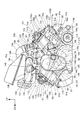
図4は、内燃機関31を示す要部左側面図である。
内燃機関31の前バンク31Aには、クランクケース81の前部上部に順に重ねるように取付けられた前シリンダブロック91、前シリンダヘッド92、スペーサ部材93及び前ヘッドカバー94(図2参照)を備える。前シリンダブロック91及び後シリンダブロック96は、それぞれ内部に筒状のシリンダ91a,96aを備え、シリンダ91a,96a内にピストンが移動可能に嵌合されている。
クランクケース81には、クランク軸82の上方に配置された駆動軸103が回転可能に支持されている。駆動軸103は、クランク軸82と平行に配置され、カム山を備えるカムロブ103aが一体に形成されるとともに従動ギヤ109が取付けられている。
FIG. 4 is a left side view of the main part showing the
The
A
スペーサ部材93は、前シリンダヘッド92と前ヘッドカバー94との間に配置されている。スペーサ部材93には、クランク軸82と平行に配置されたカム軸104が回転可能に支持され、また、スペーサ部材93には、排気ロッカーアーム107を支持するロッカーアームシャフト108が取付けられている。
排気ロッカーアーム107は、カム軸104に設けられた排気カム104b(図6参照)に駆動される。また、排気ロッカーアーム107は、前シリンダブロック91と前シリンダヘッド92との間に形成された燃焼室内に開口する排気ポートを開閉する排気用機関弁を駆動させる。
また、カム軸104には吸気カム104a(図6参照)が設けられ、吸気カム104aが、燃焼室内に開口する吸気ポートを開閉する吸気用機関弁を直接駆動させる。
駆動軸103には一対のドライブスプロケット111,111が取付けられ、カム軸104にはカムスプロケット112が取付けられ、ドライブスプロケット111,111の一方と、カムスプロケット112とにカムチェーン113が掛け渡されている。
The
The
The
A pair of
ホルダ部材98には、クランク軸82と平行に配置されたカム軸104が回転可能に支持され、また、ホルダ部材98には、スペーサ部材93と同じように、排気ロッカーアーム107を支持するロッカーアームシャフト108が取付けられている。
排気ロッカーアーム107は、カム軸104に設けられた排気カムに駆動される。また、排気ロッカーアーム107は、後シリンダブロック96と後シリンダヘッド97との間に形成された燃焼室内に開口する排気ポートを開閉する排気用機関弁を駆動させる。
前バンク31Aと同じように、カム軸104にはカムスプロケット112が取付けられ、駆動軸103に取付けられたドライブスプロケット111,111の他方と、カムスプロケット112とにカムチェーン113が掛け渡されている。
A
The
As with the
クランクケース81の一側面(左側面)にはケースカバー116が取付けられている。
クランク軸82には、駆動ギヤ118が取付けられ、駆動ギヤ118に駆動軸103の従動ギヤ109が噛み合い、クランク軸82の動力が駆動軸103に伝達される。
クランクケース81には、クランク軸82に平行に配置されるとともにクランク軸82及び駆動軸103よりも前方に配置された一対の中間軸125,126が回転可能に支持されている。中間軸125,126は、上下に並ぶように配置されている。中間軸125には、クランク軸82の駆動ギヤ118に噛み合う第1中間ギヤ145と、第2中間ギヤ146とが取付けられている。中間軸126には、一対の中間ギヤ147が取付けられ、一対の中間ギヤ147の一方が第2中間ギヤ146に噛み合っている。
過給機63は、平行に配置された一対のロータ軸63a,63bを備え、ロータ軸63a,63bにそれぞれロータが取付けられている。一方のロータ軸63aにはロータ軸ギヤ148が取付けられ、ロータ軸ギヤ148は、中間軸126の一対の中間ギヤ147の他方に噛み合っている。
A
A
A pair of
The
上記した駆動ギヤ118、中間軸125,126、第1中間ギヤ145、第2中間ギヤ146及び一対の中間ギヤ147は、クランク軸82から過給機63へ動力を伝達する動力伝達部83を構成している。
クランク軸82の一方の軸端、駆動軸103、従動ギヤ109、ドライブスプロケット111,111、動力伝達部83及び過給機63は、ケースカバー116で車体側方から覆われている。
ケースカバー116は、一体成形されたケースカバー本体116Gと、ケースカバー本体116Gの側縁部に着脱可能に取付けられたリッド116Hとから構成される。
ケースカバー本体116Gは、過給機支持部116a、ギヤ収容部116b及びクランクケースカバー部118eを備える。
過給機支持部116aは、過給機63の側方を覆っている。ギヤ収容部116bは、第1中間ギヤ145、第2中間ギヤ146、一対の中間ギヤ147及びロータ軸ギヤ148の下部を収容するとともに、クランクケース81及び前バンク31Aの側方を覆っている。クランクケースカバー部118eは、クランク軸82、駆動ギヤ118等の周辺のクランクケース81の側方を覆っている。
The
One shaft end of the
The
The case cover
The
ケースカバー116の後部には、駆動軸103の動力(即ち、クランク軸82の動力)を利用して作動する高圧燃料ポンプ117が支持されている。
高圧燃料ポンプ117は、駆動軸103に設けられたカムロブ(カム山を有する断面略卵形の部分)103aにより駆動される。高圧燃料ポンプ117で高圧となった燃料は、前シリンダヘッド92及び後シリンダヘッド97にそれぞれ設けられた燃料噴射弁121を介して燃焼室に噴射される。
図3及び図4において、ケースカバー116は、ギヤ収容部116bの後壁116jにポンプ台座部116kが一体に形成されている。ポンプ台座部116kには、高圧燃料ポンプ117に設けられた板状のフランジ部117aが一対のボルト119で締結され、これによって、ケースカバー116に高圧燃料ポンプ117が固定されている。
後バンク31Bの後方のクランクケース81の後部上部には、クッションユニット123(図1参照)の上端部を支持するクッション上端支持部81aが上方に突出するように形成され、クッション上端支持部81aには、前後にそれぞれ取付け穴81b,81bが開けられている。
A high-
The high-
3 and 4, the
A cushion upper
図5は、内燃機関31に接続された吸気装置61を示す模式図である。
吸気装置61は、吸気管131,131、TBW用スロットル装置132、スロットル装置133、燃料噴射弁121,121,124,124、下流側コネクティングチューブ134、過給機63、上流側コネクティングチューブ136、エアクリーナ64、バイパス管137、バイパスバルブ装置138、リリーフ管141及びリリーフバルブ142を備える。
FIG. 5 is a schematic diagram showing the
The
前シリンダヘッド92には吸気管131が設けられ、吸気管131にTBW用スロットル装置132が接続されている。TBW用スロットル装置132は、電動モータ132aと、電動モータ132aで駆動されるスロットルバルブ132bとを備え、下記TBWを構成する一部品である。
TBW(Throttle・by・Wire)は、バーハンドル33(図1参照)に設けられたスロットルグリップの回動をセンサで検知し、その検知信号を導線を通じて電動モータ132aに送り、電動モータ132aでスロットルバルブ132bを開閉するシステムである。
前バンク31Aの吸気管131には、直噴用の燃料噴射弁121の他に、吸気管131内に燃料を噴射する燃料噴射弁124が取付けられている。
The
A TBW (Throttle / by / Wire) detects rotation of a throttle grip provided on a bar handle 33 (see FIG. 1) with a sensor, sends a detection signal to the
In addition to the
後シリンダヘッド97には吸気管131が設けられ、吸気管131にスロットル装置133が接続されている。スロットル装置133は、TBW用スロットル装置132のスロットルバルブ132bと連動して開閉されるスロットルバルブ133bを備える。スロットルバルブ132b側とスロットルバルブ133b側とはロッド144(図3及び図4参照)で連結されている。
The
後バンク31Bの吸気管131には、直噴用の燃料噴射弁121の他に、吸気管131内に燃料を噴射する燃料噴射弁124が取付けられている。
TBW用スロットル装置132及びスロットル装置133には、下流側コネクティングチューブ134の二股状とされた管部134a,134aが接続されている。また、下流側コネクティングチューブ134の管部134a,134aの集合部から延びる管部134bには過給機63の一端部が接続されている。
過給機63の他端部には、上流側コネクティングチューブ136を介してエアクリーナ64が接続されている。
In addition to the
The
An
過給機63は、機械式(スーパーチャージャ)であり、2本のロータ軸63a,63b(図4参照)と、各ロータ軸63a,63bにそれぞれ設けられたロータとを内部に備え、一方のロータ軸63aに動力が伝えられて、互いに噛み合うロータ同士が回転して圧縮空気を吐出する。エアクリーナ64から上流側コネクティングチューブ136を介して過給機63に供給された空気は、過給機63で圧縮されて過給機63から下流側コネクティングチューブ134へ吐出される。この後に、空気は、下流側コネクティングチューブ134、TBW用スロットル装置132及びスロットル装置133、吸気管131,131、前シリンダヘッド92及び後シリンダヘッド97の各吸気ポートを通って燃焼室に至る。
下流側コネクティングチューブ134には、管部134bから側方に延びる管部134cが形成されている。管部134cと上流側コネクティングチューブ136とにはバイパス管137が接続され、バイパス管137の途中にバイパスバルブ装置138が設けられている。
The
The downstream connecting
バイパスバルブ装置138は、バイパスバルブ138aを備え、バイパスバルブ138aの開度を変化させることで過給機63の出力側(下流側コネクティングチューブ134〜燃焼室の範囲)の過給圧を調整する装置である。
また、バイパス管137のバイパスバルブ装置138より管部134c側と上流側コネクティングチューブ136とには、リリーフ管141が接続され、リリーフ管141の途中にリリーフバルブ142が設けられている。
リリーフバルブ142は、過給機63の出力側の過給圧が所定値を越えた場合に、圧力を過給機63の出力側から入力側へ逃がす。
The
In addition, a
The
図6は、内燃機関31の後バンク31B及びその周囲を示す斜視図であり、斜め後方から見た図である。
後シリンダヘッド97は、一対の吸気用機関弁と、一対の排気用機関弁とを開閉する動弁機構151(図4参照)を備える。
動弁機構151は、カム軸104、一対の排気ロッカーアーム107,107及びロッカーアームシャフト108(図4参照)を備える。
カム軸104は、ホルダ部材98で回転可能に支持されている。
ホルダ部材98は、一体成形されたホルダ本体152と、ホルダ本体152に複数のボルトで取付けられる一体成形品であるキャップ部材153(図4参照)とから構成される。ホルダ本体152及びキャップ部材153は、それぞれアルミニウム合金製の鋳物に機械加工が施された加工品である。
FIG. 6 is a perspective view showing the
The
The
The
The
カム軸104は、ホルダ本体152とキャップ部材153とで挟持されて支持される。
排気ロッカーアーム107,107は、カム軸104に対して直交するように前後方向に延び、ロッカーアームシャフト108(図4参照)に揺動可能に支持され、カム軸104に形成された一対の排気カムによって駆動される。
カム軸104は、一対の排気カム間に吸気カムが形成され、吸気カムによって一対の吸気用機関弁が直接に駆動される。
ロッカーアームシャフト108は、カム軸104と平行になるようにホルダ本体152に取付けられている。
The
The
In the
The
ホルダ本体152の後端部には内燃機関支持部152aが一体に設けられ、内燃機関支持部152aの両側の端部152k,152kに、左右のメインフレーム22(図2参照)と結合するためのボルト86(図2参照)がねじ結合されるめねじ152b,152bが形成されている。
図4において、前シリンダヘッド92にも、上記の動弁機構151が設けられている。但し、カム軸104は、スペーサ部材93に回転可能に支持される。スペーサ部材93は、スペーサ本体155と、スペーサ本体155に複数のボルトで取付けられるキャップ部材153とから構成される。カム軸104は、スペーサ本体155とキャップ部材153とで挟持されて支持される。ロッカーアームシャフト108は、カム軸104と平行になるようにスペーサ本体155に取付けられている。スペーサ本体155は、アルミニウム合金製の鋳物に機械加工が施された加工品である。
An internal combustion
In FIG. 4, the
図6において、過給機63の入口側に接続された上流側コネクティングチューブ136の車幅方向内側には、後端部がスロットル装置133に連結されたロッド144が配置されている。ロッド144は、上流側コネクティングチューブ136の車幅方向内側でエアクリーナ64(詳しくは、エアクリーナ64を構成するエアクリーナケース158)の下方に形成されたスペース168に前後方向に延びるように配置されている。
高圧燃料ポンプ117は、クランクケースカバー部116eの車幅方向外方に配置されるとともにギヤ収容部116bの後部に取付けられている。また、高圧燃料ポンプ117は、クランクケースカバー部116eの車幅方向外方で且つギヤ収容部116bの後方のスペース178に配置されている。以上のことから、ケースカバー116に車両側方から干渉物があった場合でも、高圧燃料ポンプ117よりも車幅方向外側に突出したギヤ収容部116bによって高圧燃料ポンプ117を保護することができる。また、スペース178に高圧燃料ポンプ117を配置してスペース178の有効利用を図ることができる。
In FIG. 6, a
The high-
図7は、内燃機関31の上部を示す左側面図である。
吸気装置61からは、上流側コネクティングチューブ136(図5参照)及びリリーフ管141(図5参照)が外されている。
過給機63は、ロータ軸63a,63b及びロータ軸63a,63bにそれぞれ取付けられるロータを収容する過給機本体63eと、過給機本体63eの上部に複数のボルトで取付けられた管部接続部63fとを備える。管部接続部63fは、その上部の左側に、下流側コネクティングチューブ134(図6参照)が接続される入口管部63cが設けられている。入口管部63cは、車幅方向外側に対して斜め前方に延びるように形成されている。
FIG. 7 is a left side view showing the upper part of the
The upstream connecting tube 136 (see FIG. 5) and the relief pipe 141 (see FIG. 5) are removed from the
The
下流側コネクティングチューブ134は、両端に設けられた管部134a,134aがそれぞれTBW用スロットル装置132及びスロットル装置133のそれぞれの上端部に接続されている。また、管部134a,134a間に設けられた下方に突出する管部134bが、過給機63の上部の右側に接続される。
TBW用スロットル装置132の車幅方向左側にはバイパスバルブ装置138が配置されている。即ち、TBW用スロットル装置132とバイパスバルブ装置138とは、車幅方向で重なるように配置されている。
バイパスバルブ装置138は、バイパスバルブ138aが取付けられたバルブ軸138cと、バイパスバルブ138aの開度を任意の角度に調整可能な電動モータ138bとを備え、電動モータ138bは、バルブ軸138cを介してバイパスバルブ138aを開閉する。
In the downstream connecting
A
The
図8は、内燃機関31の上部を示す右側面図である。
TBW用スロットル装置132とスロットル装置133とは、前下がりに延びる連結板181によって連結されている。連結板181の車幅方向内側には、過給機63の管部接続部63fに形成された出口管部63dが配置されている。出口管部63dは、下流側コネクティングチューブ134の管部134b(図7参照)に接続される。
エアクリーナ64は、エアクリーナケース158と、エアクリーナケース158内に配置されたエアクリーナエレメントとを備える。エアクリーナケース158は、エアクリーナケース本体158aと、エアクリーナケース本体158aの上部開口を塞ぐエアクリーナケースカバー158bとからなる。エアクリーナケース本体158aには、上流側コネクティングチューブ136(図5参照)が接続される。
FIG. 8 is a right side view showing the upper part of the
The
The
エアクリーナケース158は、その前端がバイパスバルブ装置138の上方に位置し、後端が過給機63の上方に位置する。また、図6に示したように、エアクリーナケース158(即ち、エアクリーナケース本体158a及びエアクリーナケースカバー158b)の後部には、下流側コネクティングチューブ134を通すための切欠き部158cが後方に開放するように形成されている。
図8において、過給機63は、スペース66内であって、前バンク31Aの吸気管131及びTBW用スロットル装置132と,後バンク31Bの吸気管131及びスロットル装置133との間のスペース176に、且つエアクリーナケース158の下方に配置される。
The
In FIG. 8, the
図9は、内燃機関31の上部を示す斜視図であり、斜め上方から見た図である。図10は、TBW用スロットル装置132、スロットル装置133及びその周辺を示す左側面図である。
図9に示すように、内燃機関31の上方のスペース66内であってスペース176内には、過給機63の入口管部63c(図7参照)と出口管部63dとが車幅方向で重なるように配置され、入口管部63cと出口管部63dとの間に、ロッド144が前後に延びるように配置されている。
FIG. 9 is a perspective view showing an upper portion of the
As shown in FIG. 9, in the
ケースカバー116は、過給機支持部116aの下方に一体に縦長のギヤ収容部116bが設けられている。ギヤ収容部116bは、その側端部に着脱可能なリッド116H(図3参照)を備える。ギヤ収容部116bには、第1中間ギヤ145(図4参照)、第2中間ギヤ146及び一対の中間ギヤ147,147と、ロータ軸ギヤ148の下部とが収容されている。このように、ケースカバー116に、過給機支持部116aと共にギヤ収容部116bを設けることで、本来の機能であるクランクケース81を側方から覆うカバー構造の他に、支持構造と収容構造とを兼ね備えるため、これらの各構造を別々に設けるのに比べて部品数を減らすことができ、コストや組付工数を削減することができる。従って、内燃機関31の組付性及び生産性を向上させることができる。
The
ギヤ収容部116bの後部内面には、車幅方向外側に突出する隆起部116dが一体に形成され、隆起部116dに駆動軸103が回転可能に嵌合している。
過給機63は、ケースカバー116の過給機支持部116aから車幅方向右方に突出するように過給機支持部116aに支持されている。これにより、過給機63を内燃機関31の車幅方向左側から前バンク31Aと後バンク31Bとの間のスペース66へ挿入するように内燃機関31に組付けることが可能になる。従って、内燃機関31の組付性を向上させることができ、生産性を高めることができるとともに、自動二輪車10(図1参照)の限られたスペース66を有効利用することができる。
A raised
The
図10に示すように、TBW用スロットル装置132は、ボディ132e、スロットル軸132c、スロットルバルブ132b(図5参照)、スロットルアーム132d及び電動モータ132aを備える。
ボディ132eは、空気の流れる空気通路が形成されている。スロットル軸132cは、ボディ132eに回動可能に支持されるとともにボディ132eの空気通路を貫通している。スロットルバルブ132bは、スロットル軸132cに取付けられるとともにボディ132eの空気通路を開閉する。スロットルアーム132dは、スロットル軸132cの端部に取付けられ、スロットルアーム132dにロッド144の前端部が連結されている。電動モータ132aは、スロットル軸132cを回動させてスロットルバルブ132bを任意の開度に開閉させる。
As shown in FIG. 10, the
The body 132e has an air passage through which air flows. The
スロットル装置133は、ボディ133e、スロットル軸133c、スロットルバルブ133b(図5参照)及びスロットルアーム133dを備える。
ボディ133eは、空気の流れる空気通路が形成されている。スロットル軸133cは、ボディ133eに回動可能に支持されるとともにボディ133eの空気通路を貫通している。スロットルバルブ133bは、スロットル軸133cに取付けられるとともにボディ132eの空気通路を開閉する。スロットルアーム133dは、スロットル軸133cの端部に取付けられ、スロットルアーム133dにロッド144の後端部が連結されている。
The
The body 133e has an air passage through which air flows. The
以上の図3及び図4に示したように、シリンダヘッドとしての前シリンダヘッド92及び後シリンダヘッド97よりも下方に位置するクランクケース81の上方に過給機63が配置された鞍乗り型車両としての自動二輪車10の過給機63付き内燃機関31において、クランクケース81は、車幅方向外側からケースカバー116に覆われ、過給機63は、ケースカバー116(詳しくは、過給機支持部116a)によって支持される。
この構成によれば、自動車と比べて車体スペースが限られた自動二輪車10(図1参照)において、過給機63を車幅方向外側からケースカバー116で支持することから、過給機63をケースカバー116に小組した状態で、ケースカバー116を車幅方向外側からクランクケース81に組付けることができる。このように、過給機63をケースカバー116を介してクランクケース81に容易に組付けることができ、クランクケース81の上方に内燃機関31の補機部品等が配置されていても、過給機63の組付性や生産性を向上させることができる。
As shown in FIGS. 3 and 4 above, the saddle-ride type vehicle in which the
According to this configuration, since the
また、図4に示したように、過給機63は、クランクケース81に収容されるクランク軸82から動力伝達部83を介して動力が伝達され、ケースカバー116は、動力伝達部83を覆う動力伝達部カバーであるので、過給機63を支持するケースカバー116で動力伝達部83を覆うことにより、部品数を減らすことができ、また、レイアウトに無駄がないため、組付性や生産性を向上させることができる。
Further, as shown in FIG. 4, the
また、内燃機関31は、燃料をシリンダブロックとしての前シリンダブロック91及び後シリンダブロック96にそれぞれ設けられたシリンダ91a,96a内に直接噴射する直噴式であって、燃料噴射用の高圧燃料ポンプ117が、ケースカバー116に取付けられるとともに側面視で後シリンダブロック96と重なるように配置されるので、後シリンダブロック96の側方に高圧燃料ポンプ117が位置することから、クランク軸82から動力を容易に伝えることができ、内燃機関31の構造をより簡素にできる。
The
また、クランクケース81に駆動軸103が回転可能に支持され、駆動軸103に、高圧燃料ポンプ117を駆動するカムロブ103aが形成され、クランク軸82に設けられた駆動ギヤ118と、駆動軸103に設けられた従動ギヤ109とが噛み合うことでクランク軸82の回転が駆動軸103に伝達されるので、クランク軸82から簡単な構造で駆動軸103に動力を伝えることができ、コストを削減することができる。
Further, the
また、図4及び図7に示したように、前シリンダヘッド92の上方にエアクリーナケース158が配置され、エアクリーナケース158と前シリンダヘッド92との間に、過給機63の過給圧を調整するバイパスバルブ装置138と、スロットル信号に応じてアクチュエータとしての電動モータ132aにてスロットルバルブ132bを開閉するTBW用スロットル装置132とが配置されるので、エアクリーナケース158と前シリンダヘッド92との間にバイパスバルブ装置138及びTBW用スロットル装置132を配置することで、自動二輪車10(図1参照)の限られた車体スペースを有効利用することができる。
As shown in FIGS. 4 and 7, an air
また、図4、図7及び図8に示したように、バイパスバルブ装置138とTBW用スロットル装置132とが、側面視で重なるので、自動二輪車10の限られた車体スペースを有効利用することができる。
また、図4に示したように、内燃機関31は、前バンク31Aと後バンク31Bとを備えるV型であって、過給機63が、前バンク31Aと後バンク31Bとの間に配置されるので、自動二輪車10の限られた車体スペースを有効利用することができる。
Further, as shown in FIGS. 4, 7, and 8, the
As shown in FIG. 4, the
また、図6及び図7に示したように、前バンク31A及び後バンク31Bの一方にTBW用スロットル装置132が設けられ、前バンク31A及び後バンク31Bの他方にスロットル装置133が設けられ、TBW用スロットル装置132及びスロットル装置133にそれぞれ備えるスロットルバルブ132b,133bが連結部材としてのロッド144によって連動可能とされ、ロッド144は、過給機63に接続される配管としての上流側コネクティングチューブ136の車幅方向内側に配置されるので、自動二輪車10における上流側コネクティングチューブ136の車幅方向内側の車体スペースであるスペース168を有効利用することができる。
Further, as shown in FIGS. 6 and 7, a
また、図4及び図6に示したように、ケースカバー116は、クランクケース81の側方を覆うクランクケースカバー部116eと、クランクケースカバー部116eよりも車幅方向外側に突出して動力伝達部83に含まれるギヤとしての第1中間ギヤ145、第2中間ギヤ146及び一対の中間ギヤ147を収容するギヤ収容部116bとを備え、高圧燃料ポンプ117は、クランクケースカバー部116eの車幅方向外方に配置されるとともにギヤ収容部116bの後部に取付けられるので、高圧燃料ポンプ117をギヤ収容部116bをよりも車幅方向内側に配置することで、車両側方からの干渉物に対して、ギヤ収容部116bによって高圧燃料ポンプ117を保護することができる。また、クランクケースカバー部116eの車幅方向外方でギヤ収容部116bの後方の車体スペースであるスペース178を有効利用することができる。
4 and 6, the
上述した実施形態は、あくまでも本発明の一態様を示すものであり、本発明の主旨を逸脱しない範囲で任意に変形及び応用が可能である。
例えば、上記実施形態において、図4及び図6に示したように、ケースカバー116のケースカバー本体116Gを一体成型部品としたが、これに限らず、ケースカバー本体116Gにおける過給機支持部116a、ギヤ収容部116b及びクランクケースカバー部116eのいずれか又は全部を別体にしても良い。
本発明は、自動二輪車10に適用する場合に限らず、自動二輪車10以外も含む鞍乗り型車両にも適用可能である。なお、鞍乗り型車両とは、車体に跨って乗車する車両全般を含み、自動二輪車(原動機付き自転車も含む)のみならず、ATV(不整地走行車両)に分類される三輪車両や四輪車両を含む車両である。
The above-described embodiment is merely an aspect of the present invention, and can be arbitrarily modified and applied without departing from the gist of the present invention.
For example, in the above embodiment, as shown in FIGS. 4 and 6, the case cover
The present invention is not limited to the case where the present invention is applied to the
10 自動二輪車(鞍乗り型車両)
31 内燃機関
31A 前バンク
31B 後バンク
63 過給機
81 クランクケース
82 クランク軸
83 動力伝達部
91 前シリンダブロック(シリンダブロック)
91a,96a シリンダ
92 前シリンダヘッド(シリンダヘッド)
96 後シリンダブロック(シリンダブロック)
97 後シリンダヘッド(シリンダヘッド)
103 駆動軸
103a カムロブ
109 従動ギヤ
116 ケースカバー
117 高圧燃料ポンプ
118 駆動ギヤ
132 TBW用スロットル装置
132a 電動モータ(アクチュエータ)
132b,133b スロットルバルブ
133 スロットル装置
136 上流側コネクティングチューブ(配管)
138 バイパスバルブ装置
144 ロッド(連結部材)
158 エアクリーナケース
10 Motorcycles (saddle-ride type vehicles)
31
91a,
96 Rear cylinder block (cylinder block)
97 Rear cylinder head (cylinder head)
DESCRIPTION OF
132b,
138
158 Air cleaner case
Claims (9)
前記クランクケース(81)は、車幅方向外側からケースカバー(116)に覆われ、前記過給機(63)は、前記ケースカバー(116)によって支持されることを特徴とする鞍乗り型車両の過給機付き内燃機関。 In the internal combustion engine with a supercharger of the saddle-ride type vehicle in which the supercharger (63) is disposed above the crankcase (81) located below the cylinder head (92, 97),
The crankcase (81) is covered with a case cover (116) from the outside in the vehicle width direction, and the supercharger (63) is supported by the case cover (116). Internal combustion engine with a supercharger.
Priority Applications (3)
| Application Number | Priority Date | Filing Date | Title |
|---|---|---|---|
| JP2016069445A JP6270897B2 (en) | 2016-03-30 | 2016-03-30 | Internal combustion engine with supercharger for saddle-ride type vehicles |
| EP17159305.6A EP3225809B1 (en) | 2016-03-30 | 2017-03-06 | Internal combustion engine with supercharger for saddle-ride type vehicle |
| US15/456,126 US10526982B2 (en) | 2016-03-30 | 2017-03-10 | Internal combustion engine with supercharger for saddle-ride type vehicle |
Applications Claiming Priority (1)
| Application Number | Priority Date | Filing Date | Title |
|---|---|---|---|
| JP2016069445A JP6270897B2 (en) | 2016-03-30 | 2016-03-30 | Internal combustion engine with supercharger for saddle-ride type vehicles |
Publications (2)
| Publication Number | Publication Date |
|---|---|
| JP2017180325A true JP2017180325A (en) | 2017-10-05 |
| JP6270897B2 JP6270897B2 (en) | 2018-01-31 |
Family
ID=58264407
Family Applications (1)
| Application Number | Title | Priority Date | Filing Date |
|---|---|---|---|
| JP2016069445A Active JP6270897B2 (en) | 2016-03-30 | 2016-03-30 | Internal combustion engine with supercharger for saddle-ride type vehicles |
Country Status (3)
| Country | Link |
|---|---|
| US (1) | US10526982B2 (en) |
| EP (1) | EP3225809B1 (en) |
| JP (1) | JP6270897B2 (en) |
Cited By (3)
| Publication number | Priority date | Publication date | Assignee | Title |
|---|---|---|---|---|
| JP2020165390A (en) * | 2019-03-29 | 2020-10-08 | 本田技研工業株式会社 | Internal combustion engine with supercharger |
| JP2020165391A (en) * | 2019-03-29 | 2020-10-08 | 本田技研工業株式会社 | Internal combustion engine with supercharger |
| JP2020204297A (en) * | 2019-06-18 | 2020-12-24 | 本田技研工業株式会社 | Multi-cylinder internal combustion engine |
Families Citing this family (11)
| Publication number | Priority date | Publication date | Assignee | Title |
|---|---|---|---|---|
| JP6842342B2 (en) * | 2017-03-30 | 2021-03-17 | 本田技研工業株式会社 | Internal combustion engine drive structure |
| JP6887943B2 (en) | 2017-12-28 | 2021-06-16 | 本田技研工業株式会社 | Saddle-type vehicle |
| US10934928B1 (en) | 2019-07-17 | 2021-03-02 | Brunswick Corporation | Lubrication apapratus configurations for marine engines having a supercharger |
| US11511840B1 (en) | 2019-07-17 | 2022-11-29 | Brunswick Corporation | Marine engines having a supercharger |
| US10927745B1 (en) * | 2019-07-17 | 2021-02-23 | Brunswick Corporation | Cooling apparatus configurations for marine engines having a supercharger |
| US10981636B1 (en) | 2019-07-17 | 2021-04-20 | Brunswick Corporation | Marine engines having a supercharger |
| US11073116B1 (en) | 2019-09-25 | 2021-07-27 | Brunswick Corporation | Cooling systems for marine engines having a supercharger |
| US10975762B1 (en) | 2019-10-23 | 2021-04-13 | Brunswick Corporation | Marine engines having a supercharger and charge air coolers |
| US11459943B1 (en) | 2019-12-20 | 2022-10-04 | Brunswick Corporation | Sealing configurations for marine engines having a supercharger and charge air cooler |
| WO2021176720A1 (en) * | 2020-03-06 | 2021-09-10 | 本田技研工業株式会社 | Intake control device for saddle-type vehicle internal combustion engine |
| US11708787B2 (en) * | 2021-11-24 | 2023-07-25 | Kawasaki Motors, Ltd. | Utility vehicle |
Citations (4)
| Publication number | Priority date | Publication date | Assignee | Title |
|---|---|---|---|---|
| JPS58174120A (en) * | 1982-04-07 | 1983-10-13 | Yamaha Motor Co Ltd | Engine with turbosupercharger |
| JPH0270920A (en) * | 1988-09-02 | 1990-03-09 | Yamaha Motor Co Ltd | Motorcycle equipped with engine having supercharger |
| JPH03119545U (en) * | 1990-03-20 | 1991-12-10 | ||
| JP2013204544A (en) * | 2012-03-29 | 2013-10-07 | Honda Motor Co Ltd | Internal combustion engine with supercharger of straddle-type vehicle |
Family Cites Families (9)
| Publication number | Priority date | Publication date | Assignee | Title |
|---|---|---|---|---|
| DD228983A3 (en) * | 1983-05-30 | 1985-10-23 | Zschopau Motorrad Veb | ARRANGEMENT AND TRAINING OF A PISTON PUMP FOR A TWO-STROKE INTERNAL COMBUSTION ENGINE WITH MIXTURE INJECTION |
| US5263463A (en) * | 1992-05-19 | 1993-11-23 | Perry Leroy R | Motorcycle compact supercharging apparatus |
| US6105558A (en) * | 1995-05-12 | 2000-08-22 | Bushling; William | Supercharging apparatus |
| US7549493B1 (en) * | 2006-02-28 | 2009-06-23 | Jones Daniel W | Wet belt supercharger drive for a motorcycle |
| JP5899591B2 (en) * | 2012-02-21 | 2016-04-06 | 株式会社ケーヒン | V-type engine intake system for vehicles |
| JP5898775B2 (en) | 2012-09-13 | 2016-04-06 | 川崎重工業株式会社 | Turbocharged engine |
| EP2833038B1 (en) * | 2013-07-29 | 2018-05-09 | Helmut-Schmidt-Universität Hamburg | Valve for field sensitive liquids and hydraulic system with such a valve |
| JP6235394B2 (en) * | 2014-03-28 | 2017-11-22 | 本田技研工業株式会社 | Turbocharged engine |
| JP6298488B2 (en) * | 2016-03-30 | 2018-03-20 | 本田技研工業株式会社 | Internal combustion engine for saddle-ride type vehicles |
-
2016
- 2016-03-30 JP JP2016069445A patent/JP6270897B2/en active Active
-
2017
- 2017-03-06 EP EP17159305.6A patent/EP3225809B1/en not_active Not-in-force
- 2017-03-10 US US15/456,126 patent/US10526982B2/en not_active Expired - Fee Related
Patent Citations (4)
| Publication number | Priority date | Publication date | Assignee | Title |
|---|---|---|---|---|
| JPS58174120A (en) * | 1982-04-07 | 1983-10-13 | Yamaha Motor Co Ltd | Engine with turbosupercharger |
| JPH0270920A (en) * | 1988-09-02 | 1990-03-09 | Yamaha Motor Co Ltd | Motorcycle equipped with engine having supercharger |
| JPH03119545U (en) * | 1990-03-20 | 1991-12-10 | ||
| JP2013204544A (en) * | 2012-03-29 | 2013-10-07 | Honda Motor Co Ltd | Internal combustion engine with supercharger of straddle-type vehicle |
Cited By (5)
| Publication number | Priority date | Publication date | Assignee | Title |
|---|---|---|---|---|
| JP2020165390A (en) * | 2019-03-29 | 2020-10-08 | 本田技研工業株式会社 | Internal combustion engine with supercharger |
| JP2020165391A (en) * | 2019-03-29 | 2020-10-08 | 本田技研工業株式会社 | Internal combustion engine with supercharger |
| JP7204566B2 (en) | 2019-03-29 | 2023-01-16 | 本田技研工業株式会社 | internal combustion engine with supercharger |
| JP2020204297A (en) * | 2019-06-18 | 2020-12-24 | 本田技研工業株式会社 | Multi-cylinder internal combustion engine |
| JP7249213B2 (en) | 2019-06-18 | 2023-03-30 | 本田技研工業株式会社 | multi-cylinder internal combustion engine |
Also Published As
| Publication number | Publication date |
|---|---|
| US10526982B2 (en) | 2020-01-07 |
| US20170284319A1 (en) | 2017-10-05 |
| EP3225809B1 (en) | 2019-02-06 |
| JP6270897B2 (en) | 2018-01-31 |
| EP3225809A1 (en) | 2017-10-04 |
Similar Documents
| Publication | Publication Date | Title |
|---|---|---|
| JP6270897B2 (en) | Internal combustion engine with supercharger for saddle-ride type vehicles | |
| WO2014097774A1 (en) | Supercharging system for engine | |
| JP4531029B2 (en) | Intake device for V-type internal combustion engine | |
| JP6298488B2 (en) | Internal combustion engine for saddle-ride type vehicles | |
| EP2339149B1 (en) | Saddle-ride-type vehicle | |
| JP5339604B2 (en) | Motorcycle | |
| JP5339602B2 (en) | Motorcycle | |
| JP5339603B2 (en) | Motorcycle | |
| EP3499006B1 (en) | Saddle-type vehicle | |
| JP4901619B2 (en) | Breather device for internal combustion engine | |
| JP5712024B2 (en) | Saddle riding vehicle | |
| US10302004B2 (en) | Water pump unit | |
| JP5856215B2 (en) | Saddle riding vehicle | |
| JP5869611B2 (en) | Saddle riding vehicle | |
| JP5372571B2 (en) | Motorcycle | |
| JP2012207572A (en) | Throttle control device | |
| JP6011319B2 (en) | Intake system of motorcycle | |
| JP5311650B2 (en) | Motorcycle | |
| JP6197279B2 (en) | Engine unit for motorcycle | |
| JP5834867B2 (en) | Intake control device | |
| JP5757762B2 (en) | Engine throttle control device | |
| JP2018083606A (en) | Arrangement structure for reservoir tank |
Legal Events
| Date | Code | Title | Description |
|---|---|---|---|
| A131 | Notification of reasons for refusal |
Free format text: JAPANESE INTERMEDIATE CODE: A131 Effective date: 20170919 |
|
| A521 | Request for written amendment filed |
Free format text: JAPANESE INTERMEDIATE CODE: A523 Effective date: 20171106 |
|
| TRDD | Decision of grant or rejection written | ||
| A01 | Written decision to grant a patent or to grant a registration (utility model) |
Free format text: JAPANESE INTERMEDIATE CODE: A01 Effective date: 20171205 |
|
| A61 | First payment of annual fees (during grant procedure) |
Free format text: JAPANESE INTERMEDIATE CODE: A61 Effective date: 20171226 |
|
| R150 | Certificate of patent or registration of utility model |
Ref document number: 6270897 Country of ref document: JP Free format text: JAPANESE INTERMEDIATE CODE: R150 |