JP2017178510A - Conveyance conduit of pneumatic conveyor, pneumatic conveyor - Google Patents

Conveyance conduit of pneumatic conveyor, pneumatic conveyor Download PDF

Info

Publication number
JP2017178510A
JP2017178510A JP2016065676A JP2016065676A JP2017178510A JP 2017178510 A JP2017178510 A JP 2017178510A JP 2016065676 A JP2016065676 A JP 2016065676A JP 2016065676 A JP2016065676 A JP 2016065676A JP 2017178510 A JP2017178510 A JP 2017178510A
Authority
JP
Japan
Prior art keywords
pipe
air
downward
transparent
pipeline
Prior art date
Legal status (The legal status is an assumption and is not a legal conclusion. Google has not performed a legal analysis and makes no representation as to the accuracy of the status listed.)
Pending
Application number
JP2016065676A
Other languages
Japanese (ja)
Inventor
栄一 成川
Eiichi Narukawa
栄一 成川
敏晴 田中
Toshiharu Tanaka
敏晴 田中
武雄 堀
Takeo Hori
武雄 堀
功次 能島
Koji Nojima
功次 能島
Current Assignee (The listed assignees may be inaccurate. Google has not performed a legal analysis and makes no representation or warranty as to the accuracy of the list.)
Taiwa Seiki Corp
Original Assignee
Taiwa Seiki Corp
Priority date (The priority date is an assumption and is not a legal conclusion. Google has not performed a legal analysis and makes no representation as to the accuracy of the date listed.)
Filing date
Publication date
Application filed by Taiwa Seiki Corp filed Critical Taiwa Seiki Corp
Priority to JP2016065676A priority Critical patent/JP2017178510A/en
Publication of JP2017178510A publication Critical patent/JP2017178510A/en
Priority to JP2021067434A priority patent/JP7041984B2/en
Pending legal-status Critical Current

Links

Images

Abstract

PROBLEM TO BE SOLVED: To enable visual confirmation of a conveyance state of an object to be conveyed over a long period of time at a portion where the object to be conveyed is directed downward when conveying the object to be conveyed by pneumatic pressure.SOLUTION: A conveyance conduit of a pneumatic conveyor comprises: a conveyance conduit body through which an object to be conveyed that is conveyed by pneumatic pressure passes and whose primary side is connected to an input part; a downward conduit for conveying the object to be conveyed downward, whose primary side is connected to a secondary side of the conveyance conduit body; and a transparent conduit extending straight, whose primary side is connected to a secondary side of the downward conduit. The inner diameter of the transparent conduit is larger than the inner diameter of the downward conduit, and an inner peripheral surface thereof is arranged on the outer side from an inner peripheral surface of the downward conduit in a diameter direction.SELECTED DRAWING: Figure 2

Description

本発明は、空気圧により搬送物を搬送する空気式搬送機の搬送管路、およびその搬送管路を含む空気式搬送機に関する。   The present invention relates to a conveyance pipeline of a pneumatic conveyance device that conveys a conveyance object by air pressure, and a pneumatic conveyance device including the conveyance pipeline.

空気式搬送機の一例として、搬送物としての玄米を空気圧で搬送するものが存在し、玄米を投入する投入部としてのタンクと、搬送物が通過する搬送経路と、搬送経路の末端に接続される精米装置とを備えたものが存在する(特許文献1)。   As an example of a pneumatic transporter, there is one that transports brown rice as a transported object by air pressure, and it is connected to a tank as an input unit for feeding the brown rice, a transport path through which the transported substance passes, and a terminal of the transport path. There are those equipped with a rice milling apparatus (Patent Document 1).

この搬送経路は、タンクの下から排出された玄米を、水平に搬送した後に、一旦上方へ搬送してから精米装置の上方へ搬送するものである。そして玄米の搬送状態を目視できるようにするために、搬送経路の一部に透明管を配管してあった。より詳しくは透明管は、タンクの下方において玄米を水平に搬送する部分と、玄米を上方へ搬送する部分に配管されていた。   In this conveyance path, the brown rice discharged from the bottom of the tank is conveyed horizontally, then once upward, and then conveyed upward of the rice milling apparatus. And in order to be able to visually check the conveyance state of brown rice, the transparent tube was piped in a part of conveyance path | route. In more detail, the transparent pipe was piped in the part which conveys brown rice horizontally in the lower part of a tank, and the part which conveys brown rice upwards.

特開平11−47621号公報JP 11-47621 A

しかしながら特許文献1の空気式搬送機は、玄米が勢いよく移動するので、透明管路の内面には玄米との摩擦による傷が付き、そのうちに透明管が白濁化してきて搬送状態を充分に目視できなくなる。したがって長期間に亘って搬送物の搬送状態を目視できるようにすることが望まれる。   However, in the pneumatic conveying machine of Patent Document 1, since the brown rice moves vigorously, the inner surface of the transparent conduit is scratched by friction with the brown rice, and the transparent tube becomes clouded over time, and the state of conveyance is sufficiently visually observed. become unable. Therefore, it is desirable to make it possible to visually check the transport state of the transported object over a long period of time.

また特許文献1の空気搬送機は、精米装置の近傍では、搬送物を下方に向かって搬送している。玄米の損傷を抑えるためには精米装置の近傍では、できるだけ遅い搬送速度になっていることが望ましい。しかしながら特許文献1の空気搬送機では、搬送経路の末端部において玄米の搬送状態を確認することができない。   Moreover, the air conveyance machine of patent document 1 is conveying the conveyed product toward the downward direction in the vicinity of the rice milling apparatus. In order to suppress brown rice damage, it is desirable that the conveyance speed be as slow as possible in the vicinity of the rice milling apparatus. However, in the pneumatic conveyance machine of patent document 1, the conveyance state of brown rice cannot be confirmed in the terminal part of a conveyance path | route.

本発明は上記実情を考慮して創作されたものであり、その目的は搬送物を空気圧で搬送する場合に、搬送物を下方に向かわせる部分において、長期間に亘って搬送物の搬送状態を目視で確認できるようにすることである。   The present invention has been created in consideration of the above circumstances, and the purpose of the present invention is to convey the conveyed state of the conveyed object over a long period at the portion where the conveyed object is directed downward when the conveyed object is pneumatically conveyed. It is to be able to confirm visually.

本発明の空気式搬送機の搬送管路は、空気圧で搬送する搬送物が通過する搬送管路本体であってその一次側を投入部に接続する搬送管路本体と、搬送物を下方へ向かって搬送する下向き管路であってその一次側を搬送管路本体の二次側に接続する下向き管路と、真っ直ぐに延長すると共に透明な透明管路であってその一次側を下向き管路の二次側に接続する透明管路とを備えるものとするそして、透明管路は、その内径を下向き管路の内径よりも大きくすると共に、その内周面を下向き管路の内周面よりも口径方向外側に配置してあるものである。なお、一次側とは空気や搬送物が入ってくる側であり、二次側とは空気や搬送物が出ていく側である。   The conveyance pipeline of the pneumatic conveying machine of the present invention is a conveyance pipeline main body through which an article conveyed by air pressure passes, the conveyance pipeline main body connecting the primary side to the input unit, and the conveyance article downward. A downward pipeline that transports the primary side to the secondary side of the transport pipeline main body, and a transparent tube that extends straight and is transparent, the primary side of the downward pipeline A transparent pipe connected to the secondary side, and the transparent pipe has an inner diameter larger than an inner diameter of the downward pipe and an inner peripheral surface thereof smaller than the inner peripheral face of the downward pipe. It is arranged on the outer side in the aperture direction. Note that the primary side is the side where air and transported goods enter, and the secondary side is the side where air and transported goods exit.

上記した搬送管路は、以下のような空気式搬送機に用いられることが望ましい。
すなわち、空気式搬送機は、上記した搬送管路の他に、搬送物および空気の共通の入口並びに別々に分かれた空気の排気口および搬送物の排出口を備える空気分離装置であって共通の入口を搬送管路本体の二次側に接続すると共に搬送物の排出口を下向き管路の一次側に接続する空気分離装置と、空気の排気口側に接続する空気の吸引装置と、透明管路の二次側に接続するロータリーバルブとを備えるものとする。そしてロータリーバルブの内部は、透明管路の外側から目視可能であるものとする。
It is desirable that the above-described transport pipeline is used in the following pneumatic transport machine.
In other words, the pneumatic transporter is an air separation apparatus having a common inlet for the transported object and air, an air outlet for separately separating the air, and an outlet for the transported object, in addition to the above-described transport pipeline. An air separation device for connecting the inlet to the secondary side of the main body of the transport pipe and a discharge port for the conveyed product to the primary side of the downward pipe, an air suction device for connecting to the air outlet, and a transparent tube And a rotary valve connected to the secondary side of the road. And the inside of a rotary valve shall be visible from the outer side of a transparent pipe line.

本発明の空気式搬送機の搬送管路によれば、透明管路の内周面を下向き管路の内周面よりも口径方向外側に配置してあるので、たとえば下向き管路の内周面と透明管路の内周面を口径方向に一致させたものに比べれば、下向き管路の内周面に接触して搬送された搬送物が透明管路の内周面には接触しづらくなり、その結果、長期間に亘って透明管路の外側から搬送物の搬送状態を目視できるようになる。   According to the conveyance pipeline of the pneumatic conveyance machine of the present invention, the inner circumferential surface of the transparent pipeline is arranged on the outer side in the caliber direction than the inner circumferential surface of the downward pipeline, so for example, the inner circumferential surface of the downward pipeline Compared with the case where the inner peripheral surface of the transparent pipe is aligned with the inner diameter of the transparent pipe, it is difficult for the conveyed product that is transported in contact with the inner peripheral face of the downward pipe to contact the inner peripheral face of the transparent pipe. As a result, the transported state of the transported object can be visually observed from the outside of the transparent conduit over a long period of time.

また透明管路の下側にロータリーバルブを接続した空気式搬送機によれば、ロータリーバルブの内部を透明管路から目視できるようになるので、ロータリーバルブの清掃時期を判断し易くなる。   In addition, according to the pneumatic conveyance machine in which the rotary valve is connected to the lower side of the transparent pipeline, the inside of the rotary valve can be seen from the transparent pipeline, so that it is easy to determine the cleaning time of the rotary valve.

第一実施形態の空気式搬送機を示す全体図である。It is a general view showing a pneumatic conveyance machine of a first embodiment. 第一実施形態の空気式搬送機の要部を示す正面方向から視た断面図である。It is sectional drawing seen from the front direction which shows the principal part of the pneumatic carrier of 1st embodiment. 図2のA−A線断面図である。It is the sectional view on the AA line of FIG. 第一実施形態の空気式搬送機の空気分離減速システムの平面図である。It is a top view of the air separation deceleration system of the pneumatic conveyance machine of a first embodiment. 第一実施形態の空気式搬送機の要部を示す側面図である。It is a side view which shows the principal part of the pneumatic conveying machine of 1st embodiment. 第二実施形態の空気式搬送機を示す全体図である。It is a general view which shows the pneumatic conveyance machine of 2nd embodiment. 第二実施形態の空気式搬送機の要部を示す正面方向から視た断面図である。It is sectional drawing seen from the front direction which shows the principal part of the pneumatic carrier of 2nd embodiment.

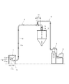
本発明が適用された第一実施形態の空気式搬送機は、空気を吸い込むことにより気流を発生させ、その気流により搬送物を搬送する空気吸引式である。そして第一実施形態の空気式搬送機は、図1に示すように、搬送物を投入する投入部としてのホッパー1、搬送物を空気と共に通過させる搬送管路2、搬送管路2を通過させた搬送物を貯留する貯留タンク3、搬送管路2の中間部から搬送管路2の長さ方向とは別方向に空気を排気する排気管4、排気管4の中間部に接続する集塵装置5と、排気管4の末端に接続する吸引装置6を備える。中間部とは、物の長さ方向の両端以外の部分であり、両端のちょうど真ん中にという意味に限定されない。   The pneumatic conveying machine of the first embodiment to which the present invention is applied is an air suction type that generates an air flow by sucking air and conveys a conveyed product by the air flow. As shown in FIG. 1, the pneumatic transfer machine of the first embodiment passes through a hopper 1 as an input unit for loading a conveyed product, a conveying line 2 that allows the conveyed item to pass along with air, and a conveying line 2. The storage tank 3 for storing the conveyed product, the exhaust pipe 4 for exhausting air in the direction different from the length direction of the transport pipe 2 from the intermediate part of the transport pipe 2, and the dust collection connected to the intermediate part of the exhaust pipe 4 A device 5 and a suction device 6 connected to the end of the exhaust pipe 4 are provided. An intermediate part is a part other than the both ends of the length direction of a thing, and is not limited to the meaning of being in the middle of both ends.

ホッパー1は、下方に向けて内径が小さくなる漏斗形状の容器であって、上側の開口端が投入口、下側の開口端が出口になっている。   The hopper 1 is a funnel-shaped container having an inner diameter that decreases downward, and has an upper opening end serving as an inlet and a lower opening end serving as an outlet.

集塵装置5は、搬送物よりも小さな微粒子(ダスト)を空気から分離し、分離した微粒子をダストタンク(符号省略)に溜め、微粒子が除去された空気を吸引装置6に吸引させるものである。なお搬送物の吸引時にはダストタンクの出口は閉鎖されており、必要に応じて開放して、ダストを排出する。   The dust collector 5 separates fine particles (dust) smaller than the conveyed product from the air, collects the separated fine particles in a dust tank (reference number omitted), and causes the suction device 6 to suck the air from which the fine particles have been removed. . Note that the outlet of the dust tank is closed when the conveyed product is sucked, and is opened as necessary to discharge the dust.

吸引装置6は、たとえばブロワで、空気吸引側を排気管4に接続し、排気側を外気に開放してある。   The suction device 6 is, for example, a blower, and the air suction side is connected to the exhaust pipe 4 and the exhaust side is opened to the outside air.

搬送管路2は、ホッパー1の出口に一次側の開口端を接続するシャッター装置11、シャッター装置11の二次側の開口端に対して一次側の開口端を接続する搬送管路本体12、搬送管路本体12の二次側の開口端に対して一次側の開口端を接続する空気分離減速システム13、空気分離減速システム13のうち搬送物を排出する二次側の開口端に対して一次側の開口端を接続すると共に搬送物を下方へ向かって搬送する透明な透明管路15、透明管路15の二次側の開口端と貯留タンク3の入口との間に接続するロータリーバルブ14を備える。なお接続には、たとえば本実施形態では後述するフランジ部同士の接合が用いられるが、接続箇所の気密が保てれば、それ以外の接合を用いても良い。   The conveyance pipe line 2 includes a shutter device 11 that connects the primary side opening end to the outlet of the hopper 1, a conveyance pipe body 12 that connects the primary side opening end to the secondary side opening end of the shutter device 11, The air separation speed reduction system 13 that connects the primary side opening end to the secondary side opening end of the transport pipe main body 12, and the secondary side opening end that discharges the conveyed product in the air separation speed reduction system 13. A transparent transparent pipe 15 that connects the open end of the primary side and conveys the conveyed product downward, and a rotary valve that is connected between the open end of the secondary side of the transparent pipe 15 and the inlet of the storage tank 3. 14. For the connection, for example, in the present embodiment, a joint between flange portions described later is used, but other joints may be used as long as the connection portion is kept airtight.

シャッター装置11は、Y字状の分岐管11aと、分岐管11aの支管11cに対してその長さ方向に往復動可能に案内される調整操作部材11pとを備える。   The shutter device 11 includes a Y-shaped branch pipe 11a and an adjusting operation member 11p guided so as to be reciprocally movable in the length direction with respect to the branch pipe 11c of the branch pipe 11a.

分岐管11aは、搬送物を通過させる本管11bと、本管11bの長さ方向の中間部から分岐すると共に空気を取り入れる支管11cとを備える。なお分岐管11aは、本管11bに支管11cが合流した合流管とも言える。本管11bは、その一次側の開口端をホッパー1の出口に接続すると共に、その二次側の開口端を搬送管路本体12の一次側の開口端に接続するものである。なお支管11cは、調整操作部材11pの一部(後述する外気導入管11q)を収納する管、つまり外気導入部収納管とも言える。   The branch pipe 11a includes a main pipe 11b that allows a conveyed product to pass therethrough, and a branch pipe 11c that branches from an intermediate portion in the length direction of the main pipe 11b and takes in air. The branch pipe 11a can also be said to be a merge pipe in which the branch pipe 11c merges with the main pipe 11b. The main pipe 11 b connects the primary side opening end to the outlet of the hopper 1, and connects the secondary side opening end to the primary side opening end of the conveyance pipe main body 12. The branch pipe 11c can also be said to be a pipe that houses a part of the adjusting operation member 11p (an outside air introduction pipe 11q described later), that is, an outside air introduction part accommodation pipe.

調整操作部材11pは、支管11cの内側に接する状態で収容される外気導入管11qであって支管11cの長さ方向に往復動可能に案内されると共に長さ方向の一端部で本管11bの内部を開閉可能な外気導入管11qと、外気導入管11qをその長さ方向の他端部で塞ぐ板状の塞ぎ部11rと、塞ぎ部11rから外気導入管11qの外側に突出する調整ツマミ11sとを備える。   The adjustment operation member 11p is an outside air introduction pipe 11q accommodated in a state of being in contact with the inside of the branch pipe 11c, and is guided so as to reciprocate in the length direction of the branch pipe 11c, and at one end portion in the length direction of the main pipe 11b. An outside air introduction pipe 11q that can be opened and closed, a plate-like closing part 11r that closes the outside air introduction pipe 11q at the other end in the length direction, and an adjustment knob 11s that protrudes from the closing part 11r to the outside of the outside air introduction pipe 11q. With.

外気導入管11qの側面には吸気口(図示略)が形成されており、外気導入管11qの側面をその口径方向外側から支管11cが覆うことにより、吸気口を隠蔽するようになっている。ただし吸気口の全部を支管11cが覆うのではなく、その一部である。
より詳しく言えば、外気導入管11qを支管11cの中に深く突入すると、外気導入管11qが本管11bの内面に衝突して、本管11bの内部空間が一次側と二次側で隔離され、シャッター装置11が全閉状態になる。このとき吸気口の大部分は外気導入管11qに覆われるが、吸気口の一部は外気導入管11qに覆われることなく、外気に通じている。また外気は吸気口から支管11cの内部、本管11bの内部空間の二次側部分を経て、搬送管路本体12に取り込まれるようになっている。そして調整操作部材11pを操作して、往復動可能な外気導入管11qが支管11cに対する位置を変えることによって、外気導入管11qが本管11bの内面から離れ、調整操作部材11pの操作量に応じてシャッター装置11が所定量開き、ホッパー1の出口を通過する搬送物の量が変化すると共に、吸気口が支管11cに覆われる面積が変わり、外気導入管11qの外部と内部が通じる吸気口の開口面積(閉鎖面積)が変化するようになっている。
An intake port (not shown) is formed on the side surface of the outside air introduction pipe 11q, and the intake port is concealed by covering the side surface of the outside air introduction pipe 11q with the branch pipe 11c from the outside in the diameter direction. However, the entire intake port is not covered by the branch pipe 11c but a part thereof.
More specifically, when the outside air introduction pipe 11q penetrates deeply into the branch pipe 11c, the outside air introduction pipe 11q collides with the inner surface of the main pipe 11b, and the internal space of the main pipe 11b is isolated on the primary side and the secondary side. The shutter device 11 is fully closed. At this time, most of the intake port is covered by the outside air introduction pipe 11q, but a part of the intake port is not covered by the outside air introduction pipe 11q and communicates with the outside air. Further, outside air is taken into the transfer pipe main body 12 from the intake port through the inside of the branch pipe 11c and the secondary side portion of the internal space of the main pipe 11b. Then, by operating the adjustment operation member 11p and changing the position of the reciprocating outside air introduction pipe 11q relative to the branch pipe 11c, the outside air introduction pipe 11q is separated from the inner surface of the main pipe 11b, and according to the operation amount of the adjustment operation member 11p. As a result, the shutter device 11 opens by a predetermined amount, the amount of the conveyed product passing through the outlet of the hopper 1 changes, the area of the intake port covered by the branch pipe 11c changes, and the intake port through which the outside and inside of the outside air introduction pipe 11q communicates. The opening area (closed area) changes.

搬送管路本体12は、搬送物を上昇させてから所望の位置に搬送するもので、複数の管を接続したものである。なお複数の管のうち一つは、搬送物を真っ直ぐ上昇させる直管12aであって、この直管12aに透明な管を用いている。   The conveyance pipe main body 12 raises a conveyed product and conveys it to a desired position, and connects a plurality of tubes. One of the plurality of pipes is a straight pipe 12a that raises the conveyed product straight, and a transparent pipe is used as the straight pipe 12a.

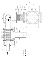
ロータリーバルブ14は図2または図4に示すように、ケーシング14aと、ケーシング14a内に回転可能に支持される繰出し羽根14bと、繰出し羽根14bの回転軸14cを回転させるモータ14mとを備えるものである。また繰出し羽根14bは、回転軸14cと、回転軸14cの周囲から等角度おきに放射状に突出する複数枚の羽根14dとを備える。ロータリーバルブ14は、ケーシング14aの内部を一次側と二次側に分断するように繰出し羽根14bが配置されており、密閉性の高いものである。そして繰出し羽根14bを回転させることによって、ケーシング14aの一次側の開口端から内部に入った搬送物が定量ずつ二次側の開口端に排出される。なおロータリーバルブ14の二次側の開口端には貯留タンク3の一次側の開口端が接続されており、貯留タンク3の二次側の開口端は、必要に応じて開閉可能となっている。   As shown in FIG. 2 or 4, the rotary valve 14 includes a casing 14a, a feeding blade 14b that is rotatably supported in the casing 14a, and a motor 14m that rotates a rotating shaft 14c of the feeding blade 14b. is there. The feeding blade 14b includes a rotating shaft 14c and a plurality of blades 14d protruding radially from the periphery of the rotating shaft 14c at equal angles. The rotary valve 14 is provided with a feeding blade 14b so as to divide the inside of the casing 14a into a primary side and a secondary side, and has high sealing performance. Then, by rotating the feeding blade 14b, a conveyed product entering the inside from the primary side opening end of the casing 14a is discharged to the secondary side opening end by a fixed amount. A secondary side opening end of the rotary valve 14 is connected to a primary side opening end of the storage tank 3, and the secondary side opening end of the storage tank 3 can be opened and closed as necessary. .

ケーシング14aは、両端が塞がれた横向きの円筒からなるケース本体部14hを主として構成されている。ケース本体部14hはその円筒の円周方向の対向箇所である上下部に搬送物の入口14iおよび出口14jを備える。またケース本体部14hの円筒の中心位置に回転軸14cをその円筒の長さ方向と平行な状態で配置すると共に、回転軸14cをケース本体部14hの外部に貫通させて、回転軸14cを回転可能に支持している。また入口14iと出口14jに搬送物を案内する入口用および出口用案内部14p,14qがケース本体部14hの上下から突出している。入口用案内部14pは、ケース本体部14hの入口14iの全周から上方に突出する筒状の入口案内部本体14sと、入口案内部本体14sの先部(上端部)からその外周全周に亘って突出する環状のフランジ部14tとを備える。入口案内部本体14sの内径は、下部に比べて上部の方が広く形成されている。なお出口用案内部14qは、入口用案内部14pとほぼ上下対称的な形状である。   The casing 14a mainly includes a case main body portion 14h made of a horizontal cylinder with both ends closed. The case main body 14h includes an inlet 14i and an outlet 14j for a conveyed product at the upper and lower portions that are opposite positions in the circumferential direction of the cylinder. In addition, the rotation shaft 14c is arranged in the center position of the cylinder of the case main body 14h in a state parallel to the length direction of the cylinder, and the rotation shaft 14c is passed through the outside of the case main body 14h to rotate the rotation shaft 14c. I support it as possible. Further, inlet and outlet guide portions 14p and 14q for guiding a conveyed product to the inlet 14i and the outlet 14j protrude from the upper and lower sides of the case main body portion 14h. The inlet guide portion 14p includes a cylindrical inlet guide portion main body 14s that protrudes upward from the entire circumference of the inlet 14i of the case main body portion 14h, and a tip portion (upper end portion) of the inlet guide portion main body 14s that extends around the outer periphery thereof. And an annular flange portion 14t that protrudes across. The inner diameter of the inlet guide body 14s is wider at the upper part than at the lower part. The outlet guide portion 14q is substantially symmetrical with the inlet guide portion 14p.

空気分離減速システム13は、搬送管路本体12の二次側の開口端に対して一次側の開口端を接続する接続する第一減速管路16と、第一減速管路16の二次側の開口端に対して一次側の開口端を接続すると共に空気を搬送物から分離させる空気分離装置17と、空気分離装置17のうち搬送物を排出する二次側の開口端に対して一次側の開口端を接続する第二減速管路18とを備える。また空気分離装置17のうち空気を排出する二次側の開口端に対して排気管4を接続してある。   The air separation decelerating system 13 includes a first decelerating line 16 that connects the open end of the primary side with respect to the open end of the secondary side of the transport pipe main body 12, and the secondary side of the first decelerating line 16. An air separation device 17 for connecting the primary side opening end to the opening end and separating the air from the conveyed product, and a primary side with respect to the secondary side opening end for discharging the conveyed product in the air separating device 17 And a second reduction line 18 connecting the open ends of the two. Further, the exhaust pipe 4 is connected to the open end of the air separation device 17 on the secondary side that discharges air.

第一減速管路16は、第一減速管路本体16aと、第一減速管路本体16aの長さ方向の両端から口径方向外側に張り出す一対のフランジ部16b,16cとを備える。
第一減速管路本体16aは、一次側の開口端の内径に比べて二次側の開口端の内径を大きくしてある。
The first reduction pipe line 16 includes a first reduction pipe line main body 16a and a pair of flange portions 16b and 16c projecting outward from the both ends in the length direction of the first reduction pipe main body 16a.
The first deceleration pipe main body 16a has an inner diameter at the secondary opening end larger than an inner diameter at the primary opening end.

第二減速管路18は、搬送物を下方へ向かって搬送する下向き管路であって、その一次側の開口端を搬送管路本体12の二次側の開口端に対して空気分離装置17を介して接続している。下向き管路としての第二減速管路18は、空気分離装置17のうち搬送物の通過方向(後述する内筒21の長さ方向)に対して湾曲する方向に延長する第1の管路40としての曲がり管路40と、第1の曲がり管路40の長さ方向に対して湾曲する方向に延長する第2の管路42としての曲がり管路42とを備える。図示の例では第1、第2の曲がり管路40,42は、一本の管路である。第1の曲がり管路40は、その一次側開口端に口径方向外側に張り出すフランジ部18aを備え、第2の曲がり管路42も、その二次側開口端に口径方向外側に張り出すフランジ部18bを備える。   The second decelerating pipe 18 is a downward pipe that conveys the conveyed product downward, and the air separating device 17 has an opening end on the primary side with respect to an opening end on the secondary side of the carrying pipe body 12. Connected through. The second deceleration line 18 as a downward line is a first line 40 that extends in the direction of bending with respect to the passing direction of the conveyed product (the length direction of the inner cylinder 21 described later) in the air separation device 17. And a bent pipe line 42 as a second pipe line 42 extending in a direction curved with respect to the length direction of the first bent pipe line 40. In the illustrated example, the first and second bent pipelines 40 and 42 are a single pipeline. The first bent pipe line 40 is provided with a flange portion 18a protruding outward in the radial direction at the primary opening end, and the second bent pipe line 42 is also a flange protruding outward in the radial direction at the secondary opening end. A portion 18b is provided.

第1の曲がり管路40は図4に示すように二本の直管部40a,40aと、二本の直管部40a,40aを接続する湾曲管部40bとを備えるものである。
二本の直管部40a,40aは、互いの長さ方向の延長線上で交差するように配置され、互いの内部空間が湾曲管部40bの内部空間によって連絡している。
湾曲管部40bは、二本の直管部40a,40aを滑らかに繋ぐように湾曲している。
As shown in FIG. 4, the first bent pipeline 40 includes two straight pipe portions 40a and 40a and a curved pipe portion 40b connecting the two straight pipe portions 40a and 40a.
The two straight pipe portions 40a, 40a are arranged so as to intersect with each other on the extension line in the length direction of each other, and the internal space of each other is connected by the internal space of the curved pipe portion 40b.
The curved tube portion 40b is curved so as to smoothly connect the two straight tube portions 40a and 40a.

第2の曲がり管路42も、第1の曲がり管路40と同じ構成であり、図5に示すように二本の直管部42a、42aと、二本の直管部42a,42aを接続する湾曲管部42bとを備えるもので、二次側の直管部42aが鉛直方向を向くものである。この二次側の直管部42aに接続するのが、透明管路15である。   The second bent pipe line 42 has the same configuration as the first bent pipe line 40, and as shown in FIG. 5, the two straight pipe parts 42a and 42a are connected to the two straight pipe parts 42a and 42a. The secondary straight tube portion 42a faces the vertical direction. The transparent conduit 15 is connected to the secondary side straight pipe portion 42a.

透明管路15は図2に示すように、真っ直ぐに延長する直管の透明管本体15aと、透明管本体15aの長さ方向の両端に接続すると共に口径方向外側に張り出す一対のフランジ部15bとを備える。   As shown in FIG. 2, the transparent pipe line 15 includes a straight pipe body 15a that extends straight, and a pair of flange portions 15b that are connected to both ends of the transparent pipe body 15a in the length direction and project outward in the radial direction. With.

透明管本体15aは、たとえば合成樹脂製で、円筒状であり、その内径が第2の曲がり管路42の二次側の直管部42aの内径よりも(より詳しくは外径よりも)大きいものである。
フランジ部15bは、透明管本体15aの長さ方向における一端部の外周をその全周に亘って包囲する円筒状の包囲枠15cと、包囲枠15cの貫通方向の一端の外周全周からその外側に突出する円環状のフランジ部本体15dとを備える。
包囲枠15cは、周方向に間隔をあけて、その半径方向に貫通する貫通穴(図示略)を備えている。
The transparent tube main body 15a is made of, for example, a synthetic resin and has a cylindrical shape, and the inner diameter thereof is larger than the inner diameter of the straight pipe portion 42a on the secondary side of the second bent pipe line 42 (more specifically, the outer diameter). Is.
The flange portion 15b includes a cylindrical surrounding frame 15c that surrounds the outer periphery of one end in the length direction of the transparent tube main body 15a over the entire periphery, and an outer periphery from the outer periphery of one end in the penetrating direction of the surrounding frame 15c. And an annular flange main body 15d that protrudes from the center.
The surrounding frame 15c includes through holes (not shown) penetrating in the radial direction at intervals in the circumferential direction.

このような一対のフランジ部15b,15bと透明管本体15aとを組み立てるときには、フランジ部15bを透明管本体15aの長さ方向の両端部に別々に差し込む。また差し込むときには、包囲枠15cが透明管本体15aの長さ方向の中央側を向き、一対のフランジ部本体15d,15dが透明管の長さ方向の両端端側を向くように配置し、ネジを貫通穴から透明管本体15aにねじ込む。そうすると、一対のフランジ部15bと透明管本体15aとが一体化して透明管路15になり、一対のフランジ部15bが透明管本体15aの長さ方向の両端に固定された状態になる。   When assembling such a pair of flange portions 15b, 15b and the transparent tube main body 15a, the flange portions 15b are separately inserted into both ends in the length direction of the transparent tube main body 15a. Further, when inserting, the surrounding frame 15c is arranged so that the center side in the length direction of the transparent tube main body 15a faces, the pair of flange portion main bodies 15d, 15d faces the both end sides in the length direction of the transparent tube, and screws are arranged. Screw into the transparent tube main body 15a from the through hole. If it does so, a pair of flange part 15b and the transparent pipe main body 15a will be integrated, and it will become the transparent pipe line 15, and it will be in the state fixed to the both ends of the length direction of the transparent pipe main body 15a.

また透明管路15は、第二減速管路18とロータリーバルブ14に接合される。より詳しくは、透明管路15の一次側の開口端のフランジ部本体15dと、第2の曲がり管路(下向き管路)42の二次側のフランジ部18bとを例えばボルト、ナットで接合すると、透明管本体15aと第2の曲がり管路42における二次側の直管部42aとは同心状に配置され、透明管路15の内周面は当該二次側の直管部42aの内周面よりも口径方向外側に配置される。また透明管路15の二次側の開口端のフランジ部本体15dと、ロータリーバルブ14の入口側のフランジ部14tとを接合すると、透明管本体15aとロータリーバルブ14の入口案内部本体14sとは同心状に配置され、入口案内部本体14sの内周面は、その入り口側において透明管本体15aの内周面よりも口径方向外側に配置される。   The transparent conduit 15 is joined to the second deceleration conduit 18 and the rotary valve 14. More specifically, when the flange portion main body 15d at the open end on the primary side of the transparent conduit 15 and the secondary flange portion 18b of the second bent conduit (downward conduit) 42 are joined with, for example, bolts and nuts. The transparent pipe body 15a and the secondary straight pipe part 42a in the second bent pipe line 42 are arranged concentrically, and the inner peripheral surface of the transparent pipe 15 is the inner side of the secondary straight pipe part 42a. It arrange | positions in a caliber direction outer side rather than a surrounding surface. Further, when the flange portion main body 15d at the secondary side opening end of the transparent conduit 15 and the flange portion 14t on the inlet side of the rotary valve 14 are joined, the transparent tube main body 15a and the inlet guide portion main body 14s of the rotary valve 14 are Arranged concentrically, the inner peripheral surface of the inlet guide main body 14s is arranged on the inlet side on the outer side in the aperture direction than the inner peripheral surface of the transparent tube main body 15a.

空気分離装置17は図2、図3に示すように、第一減速管路16の二次側の開口端に対して一次側の開口端を接続する内筒部材20と、内筒部材20が貫通する状態で収容される外筒容器30とを備える。   As shown in FIGS. 2 and 3, the air separation device 17 includes an inner cylinder member 20 that connects the primary side opening end to the secondary side opening end of the first deceleration pipe 16, and the inner cylinder member 20 includes And an outer cylinder container 30 that is accommodated in a penetrating state.

内筒部材20は、内筒21と、内筒21の長さ方向の両端から口径方向の外側に張り出す一対の内フランジ部21a、21bとを備える。   The inner cylinder member 20 includes an inner cylinder 21 and a pair of inner flange portions 21 a and 21 b that project outward from both ends in the length direction of the inner cylinder 21 in the caliber direction.

内筒21は、真っ直ぐに延長する直管である。内筒21の内径は、第一減速管路16の二次側の内径よりも大きくしてある。また内筒21は、その内部空間を搬送物が当該内部空間に突入したときの勢いを利用して慣性で通過する通過空間にすると共に、その一次側の開口端を搬送物と空気の入口22とし、その二次側の開口端を搬送物の排出口24とし、その側面には空気の排気口26を備えるものである。排気口26は、内筒21の側面にその口径方向に貫通して形成された多数の空気孔26aから構成されている。   The inner cylinder 21 is a straight pipe that extends straight. The inner diameter of the inner cylinder 21 is larger than the inner diameter of the secondary side of the first reduction pipe line 16. Further, the inner cylinder 21 uses the moment when the conveyed product enters the inner space to make the inner cylinder 21 a passing space that passes by inertia, and the primary side opening end of the inner cylinder 21 is the inlet 22 for the conveyed item and the air. The secondary side opening end is used as a discharge port 24 for a conveyed product, and the side surface thereof is provided with an air exhaust port 26. The exhaust port 26 is composed of a large number of air holes 26 a formed through the side surface of the inner cylinder 21 in the aperture direction.

外筒容器30は、内筒21をその口径方向外側に等間隔をあけて取り囲む外筒32と、外筒32の長さ方向の両端から口径方向外側に張り出す一対の外フランジ部32a,32bと、外筒32の長さ方向の中間部から分岐すると共に吸引装置側へ接続する排気筒36とを備える。   The outer cylinder container 30 includes an outer cylinder 32 that surrounds the inner cylinder 21 at equal intervals outward in the caliber direction, and a pair of outer flange portions 32a and 32b that project outward from both ends in the length direction of the outer cylinder 32 in the caliber direction. And an exhaust cylinder 36 that branches from the middle portion of the outer cylinder 32 in the length direction and is connected to the suction device side.

外筒32は、真っ直ぐに延長する直管である。そして外筒32の側面には排気筒36に通じる出口が外筒32の口径方向に貫通して形成されている。外筒32の内径は、内筒21の外径よりも大きく形成されると共に、内筒部材20の一対の内フランジ部21a、21bの外径よりも僅かに大きく形成される。そして内筒部材20を外筒32に対してその長さ方向に差し込むと、外筒32の内周面に内筒部材20の一対の内フランジ部21a,21bが嵌り込み、内筒部材20はその口径方向に移動不能に位置決めされ、内筒21は外筒32を貫通する状態となる。また一対の内フランジ部21a,21bは、外筒32の長さ方向の両側で外筒32と内筒21の口径方向の間をほぼ閉鎖する。つまり一対の内フランジ部21a,21bは、一対の閉鎖部34,34としての機能をも発揮する。   The outer cylinder 32 is a straight pipe that extends straight. An outlet communicating with the exhaust cylinder 36 is formed in the side surface of the outer cylinder 32 so as to penetrate in the caliber direction of the outer cylinder 32. The inner diameter of the outer cylinder 32 is formed to be larger than the outer diameter of the inner cylinder 21 and slightly larger than the outer diameters of the pair of inner flange portions 21 a and 21 b of the inner cylinder member 20. When the inner cylinder member 20 is inserted into the outer cylinder 32 in the length direction, the pair of inner flange portions 21a and 21b of the inner cylinder member 20 are fitted into the inner peripheral surface of the outer cylinder 32, and the inner cylinder member 20 is The inner cylinder 21 is positioned so as to be immovable in the caliber direction, and the inner cylinder 21 passes through the outer cylinder 32. The pair of inner flange portions 21 a and 21 b substantially closes the gap between the outer cylinder 32 and the inner cylinder 21 on both sides in the length direction of the outer cylinder 32. That is, the pair of inner flange portions 21a and 21b also functions as the pair of closing portions 34 and 34.

排気筒36は、外筒32の内部空間に対して分岐するように外筒32の側面から突出している。   The exhaust cylinder 36 protrudes from the side surface of the outer cylinder 32 so as to branch from the internal space of the outer cylinder 32.

一対の外フランジ部32a,32bのうち一次側の外フランジ部32aと、第一減速管路16の二次側のフランジ部16cの口径方向外側部分とは、例えばボルト、ナットで接合される。また一対の外フランジ部32a,32bのうち二次側の外フランジ部32bと、第二減速管路18の一次側のフランジ部18aの口径方向外側部分とは、同様にボルト、ナットで接合される。このように接合されることにより空気分離装置17は、第一、第二減速管路16、18と一体化される。この一体化された状態において、第一減速管路16の二次側のフランジ部16cと、第二減速管路18の一次側のフランジ部18aとは、一対の閉鎖部34,34として機能する。   Of the pair of outer flange portions 32a and 32b, the primary outer flange portion 32a and the outer side portion of the secondary flange portion 16c of the first reduction pipe line 16 are joined together by bolts and nuts, for example. Further, the outer flange portion 32b on the secondary side of the pair of outer flange portions 32a and 32b and the radially outer side portion of the flange portion 18a on the primary side of the second reduction line 18 are similarly joined with bolts and nuts. The By being joined in this way, the air separation device 17 is integrated with the first and second reduction lines 16 and 18. In this integrated state, the flange portion 16 c on the secondary side of the first reduction pipe line 16 and the flange part 18 a on the primary side of the second reduction pipe line 18 function as a pair of closing parts 34 and 34. .

一対の閉鎖部34、34のうち第一減速管路16側の閉鎖部34は、内筒部材20の一次側の内フランジ部21aと、第一減速管路16の二次側のフランジ部16cにおける口径方向内側部分とから構成される。また一対の閉鎖部34、34のうち第二減速管路18側の閉鎖部34は、内筒部材20の二次側の内フランジ部21bと、第二減速管路18の一次側のフランジ部18aとから構成される。したがって本実施形態では空気分離装置17は、第一、第二減速管路16,18の一部を含むものである。   Of the pair of closing portions 34, 34, the closing portion 34 on the first reduction pipe line 16 side includes an inner flange part 21 a on the primary side of the inner cylinder member 20 and a flange part 16 c on the secondary side of the first reduction pipe line 16. And a diametrically inner portion. Further, of the pair of closing portions 34, 34, the closing portion 34 on the second reduction pipe line 18 side includes an inner flange part 21 b on the secondary side of the inner cylinder member 20 and a flange part on the primary side of the second reduction pipe line 18. 18a. Therefore, in the present embodiment, the air separation device 17 includes a part of the first and second reduction lines 16 and 18.

上記した実施形態の空気分離減速システム13は、以下のようにして空気と搬送物の分離と搬送物の搬送速度の減速を行う。この例では、搬送物に粒状物や粉状物として、穀物の種子(より具体的には米粒)を用いるものとする。
1)シャッター装置11を全閉状態にしておき、ホッパー1に米粒を投入する。そうすると、ホッパー1内に米粒は収容されたままであり、シャッター装置11の本管11bの内部空間の二次側部分には米粒がない。また外気導入管11qの内部空間は本管11bの内部空間の二次側部分に通じ、吸気口の一部が外気に通じている。
2)吸引装置6を駆動させて搬送管路2内を負圧にし、シャッター装置11の外気導入管11qの吸気口から外気を搬送管路本体12内に取り込み、気流を発生させる。そうすると空気は、搬送管路本体12から空気分離装置17を経て排気管4へ向かい、その後、集塵装置5を経て吸引装置6の吸引側へ向かい、排気側から排出される。また吸引装置6の駆動と相前後させて、ロータリーバルブ14のモータ14mを駆動させる。
3)所定時間経過後にシャッター装置11をたとえば全開状態にして、搬送管路2へ米粒を流し込む。
4)ホッパー1から搬送管路本体12内に吸引された米粒は、気流により空気分離装置17へ向かう。
5)搬送管路本体12から第一減速管路16に米粒と空気が突入し、第一減速管路16では二次側の開口端の内径が一次側の開口端の内径に比べて広がっているので、吸引された空気と米粒が減速する。
6)第一減速管路16から内筒21に米粒と空気が突入する。内筒21の一次側の開口端の内径が第一減速管路16の二次側の開口端よりも大きいことから、空気と米粒は、内筒21の中で減速する。
空気は、内筒21の側面の排気口26を経て外筒32と内筒21の口径方向の間の内部空間に突入し、排気筒36へ向かう。
いっぽう米粒は、内筒21の側面から空気が吸引されることから減速して、その減速した勢い(慣性)で内筒21の内部空間を通過し、そのまま内筒21の排出口24から第二減速管路18へ向かう。
7−1)米粒は、第二減速管路18へ突入し、第二減速管路18(下向き管路)では一次側の開口端の内径が内筒21の二次側の開口端の内径に比べて広がっているので、米粒が減速する。第二減速管路18の第1、第2の曲がり管路40,42を通過する毎に米粒が減速し、その後に透明管路15を通過して、米粒はロータリーバルブ14に向かう。
ロータリーバルブ14の繰出し羽根14bの回転によって所定量ずつ米粒が貯留タンク3に排出される。
7−2)いっぽう空気は空気分離装置17の排気筒36から排気管4、集塵装置5を順次経て吸引装置6へ向かい、吸引装置6の外へ排出される。
The air separation decelerating system 13 of the above-described embodiment performs separation of the air and the conveyed product and deceleration of the conveyed material speed as follows. In this example, grain seeds (more specifically, rice grains) are used as the granular material or powdery material for the conveyed product.
1) The shutter device 11 is fully closed, and rice grains are put into the hopper 1. As a result, the rice grains remain contained in the hopper 1, and there are no rice grains in the secondary side portion of the internal space of the main tube 11 b of the shutter device 11. Further, the internal space of the outside air introduction pipe 11q communicates with the secondary side portion of the internal space of the main pipe 11b, and a part of the intake port communicates with the outside air.
2) The suction device 6 is driven to make the inside of the transport pipe line 2 have a negative pressure, and outside air is taken into the transport pipe body 12 from the intake port of the outside air introduction pipe 11q of the shutter device 11 to generate an air flow. As a result, the air travels from the transfer pipe main body 12 to the exhaust pipe 4 through the air separation device 17, then travels to the suction side of the suction device 6 through the dust collector 5 and is discharged from the exhaust side. Further, the motor 14m of the rotary valve 14 is driven in synchronism with the driving of the suction device 6.
3) After a predetermined time has elapsed, the shutter device 11 is fully opened, for example, and the rice grains are poured into the conveyance pipeline 2.
4) The rice grains sucked from the hopper 1 into the conveyance pipe main body 12 travel to the air separation device 17 by the air current.
5) Rice grains and air rush into the first speed reduction pipe 16 from the transport pipe main body 12, and the inner diameter of the secondary opening end is larger than the inner diameter of the primary opening end in the first speed reduction pipe 16. As a result, the sucked air and rice grains slow down.
6) Rice grains and air enter the inner cylinder 21 from the first deceleration line 16. Since the inner diameter of the opening end on the primary side of the inner cylinder 21 is larger than the opening end on the secondary side of the first deceleration pipe 16, air and rice grains are decelerated in the inner cylinder 21.
The air enters the internal space between the outer cylinder 32 and the inner cylinder 21 through the exhaust port 26 on the side surface of the inner cylinder 21, and travels toward the exhaust cylinder 36.
On the other hand, the rice grains are decelerated because air is sucked from the side surface of the inner cylinder 21, passes through the inner space of the inner cylinder 21 with the reduced momentum (inertia), and passes through the outlet 24 of the inner cylinder 21 as it is. Head to the deceleration line 18.
7-1) The rice grains enter the second reduction pipe 18, and in the second reduction pipe 18 (downward pipe), the inner diameter of the opening end on the primary side becomes the inner diameter of the opening end on the secondary side of the inner cylinder 21. The rice grain slows down as it spreads. The rice grains decelerate every time they pass through the first and second bent pipe lines 40 and 42 of the second deceleration pipe 18, and then pass through the transparent pipe 15, and the rice grains go to the rotary valve 14.
The rice grains are discharged into the storage tank 3 by a predetermined amount by the rotation of the feeding blade 14b of the rotary valve 14.
7-2) On the other hand, the air passes from the exhaust pipe 36 of the air separation device 17 through the exhaust pipe 4 and the dust collector 5 to the suction device 6 and is discharged out of the suction device 6.

また上記した透明管路15は以下の効果を有する。空気分離減速システム13で米粒を搬送しているときには、透明管路15(透明管本体15a)の外側から米粒の通過状況が確認できる。しかも例えばロータリーバルブ14のモータ14mの駆動が不測の事態により停止した場合、透明管路15に米粒が溜まることがあるが、その状況を透明管本体15aの外側から確認することができ、当該モータ14mを適切に駆動させて、透明管路15の搬送物の量が適切な量になるようにしてからから、空気式搬送機の運転を再開することができる。
また透明管路15(透明管本体15a)の内周面を第二減速管路18(下向き管路)の第2の管路42における二次側の直管部42aの内周面よりも口径方向外側に配置してあるので、たとえば下向き管路の内周面と透明管路15の内周面を口径方向に一致させたものに比べれば、下向き管路の内周面に接触して搬送された搬送物が透明管路15の内周面には接触しづらくなり、その結果、長期間に亘って透明管路15の外側から搬送物の搬送状態を目視できるようになる。
また透明管路15の下側にロータリーバルブ14を接続してあるので、空気式吸引装置を駆動していない場合には、透明管本体15aの外側からロータリーバルブ14の内部、たとえば羽根14dを目視できるようになる。羽根14dに滓が付着すると、隣り合う二枚の羽根14d,14dの間に収容される米粒の量が所定量よりも減り、定量供給機能が損なわれる。しかし羽根14dに米粒の滓が付着しているかを透明管本体15aの外側から確認できるようになり、ロータリーバルブ14の清掃時期が判断し易くなる。
Moreover, the above-described transparent conduit 15 has the following effects. When the rice grains are being conveyed by the air separation speed reduction system 13, the passing situation of the rice grains can be confirmed from the outside of the transparent conduit 15 (transparent tube body 15a). Moreover, for example, when the drive of the motor 14m of the rotary valve 14 is stopped due to an unexpected situation, rice grains may accumulate in the transparent conduit 15, but the situation can be confirmed from the outside of the transparent tube main body 15a. After the 14m is appropriately driven so that the amount of the transported material in the transparent conduit 15 becomes an appropriate amount, the operation of the pneumatic transporter can be resumed.
Further, the inner peripheral surface of the transparent conduit 15 (transparent tube main body 15a) is bored more than the inner peripheral surface of the secondary straight tube portion 42a in the second conduit 42 of the second deceleration conduit 18 (downward facing conduit). Since the inner peripheral surface of the downward pipe line and the inner peripheral surface of the transparent pipe line 15 are aligned in the caliber direction, for example, it is in contact with the inner peripheral surface of the downward pipe line. As a result, it becomes difficult for the conveyed product to come into contact with the inner peripheral surface of the transparent conduit 15, and as a result, the conveyance state of the conveyed product can be visually observed from the outside of the transparent conduit 15 over a long period of time.
Further, since the rotary valve 14 is connected to the lower side of the transparent pipe line 15, when the pneumatic suction device is not driven, the inside of the rotary valve 14, for example, the blade 14 d is visually observed from the outside of the transparent pipe body 15 a. become able to. If soot adheres to the blades 14d, the amount of rice grains accommodated between the two adjacent blades 14d, 14d is less than a predetermined amount, and the quantitative supply function is impaired. However, it becomes possible to confirm from the outside of the transparent tube main body 15a whether rice grains are attached to the blades 14d, and it becomes easy to determine the cleaning time of the rotary valve 14.

上記した第一実施系形態の空気式搬送機は、第一減速管路16、空気分離装置17、第二減速管路18の一次側部分を、搬送物の通過方向が水平になるように配置してあった。この場合、不測の事態、たとえば停電や運転の誤操作により、吸引装置6が停止するような事態、あるいは吸引装置6による吸引空気量が搬送物の搬送に必要な量よりも不足するような事態等が生じると、第一減速管路16、空気分離装置17、第二減速管路18の一次側部分で搬送物が溜まったままの状態になるおそれがある。この場合に、吸引装置6を駆動させても、搬送物の溜まりが解消せずに搬送不能に陥るおそれがある。しかも本当に搬送物が溜まったままの状態になっているのか、不明である。このような事態をできるだけ避けるようにするには、次のようにすることが望ましい。   In the pneumatic conveying machine of the first embodiment described above, the primary side portions of the first reduction pipe line 16, the air separation device 17, and the second reduction pipe line 18 are arranged so that the passing direction of the conveyed product is horizontal. It was. In this case, an unexpected situation, for example, a situation where the suction device 6 stops due to a power failure or erroneous operation, or a situation where the amount of air sucked by the suction device 6 is less than the amount necessary for transporting the transported object, etc. If this occurs, there is a risk that the conveyed product remains in the primary side portions of the first reduction pipe 16, the air separation device 17, and the second reduction pipe 18. In this case, even if the suction device 6 is driven, there is a possibility that the accumulation of the conveyed product is not eliminated and the conveyance becomes impossible. Moreover, it is unclear whether or not the transported goods are actually accumulated. In order to avoid such a situation as much as possible, it is desirable to do the following.

第二実施形態の空気式搬送機は図6、7に示すように、空気分離減速システム13について第一減速管路16、空気分離装置17、第二減速管路18の一次側部分を、一次側に対して二次側を低くなる状態にしてあることを特徴とする。より詳しくは以下の通りである。   As shown in FIGS. 6 and 7, the pneumatic conveyor of the second embodiment is configured such that the primary side portion of the first reduction pipe line 16, the air separation device 17, and the second reduction pipe line 18 in the air separation reduction system 13 is primary. The secondary side is lowered with respect to the side. More details are as follows.

第一減速管路16の一次側の開口端を接続する搬送管路本体12は、その全長の中間部に水平に配置される直管12bと、その全長の二次側の端部において当該直管12bの二次側の開口端に接続する曲がり管12cとを備えるものである。この曲がり管12cは、くの字状であって、二本の直管部12d、12eと、二本の直管部12d、12eを90度未満の角度で屈曲する形状に滑らかに接続する湾曲管部12fとを備える。また二本の直管部12d、12eのうち一本12dは、直管部12bの二次側開口端に接続され、もう一本12eはその二次側開口端が斜め下方に向かうように傾斜して配置される。   The conveyance pipe main body 12 connecting the opening end on the primary side of the first speed reduction pipe line 16 includes a straight pipe 12b disposed horizontally in the middle part of the full length, and the straight pipe 12b at the end part on the secondary side of the full length. And a bent pipe 12c connected to the open end of the secondary side of the pipe 12b. The bent pipe 12c has a U-shape, and smoothly connects the two straight pipe portions 12d and 12e and the two straight pipe portions 12d and 12e into a shape that bends at an angle of less than 90 degrees. A tube portion 12f. Of the two straight pipe portions 12d and 12e, one 12d is connected to the secondary side opening end of the straight pipe portion 12b, and the other 12e is inclined so that the secondary side opening end is inclined downward. Arranged.

第二減速管路18は、搬送管路本体12の二次側の端部における曲がり管12cと同じように、くの字状に曲がる第1の管路40としての曲がり管路40である。第1の曲がり管路40は、二本の直管部40a、40aと、二本の直管部40a、40aを90度未満の角度で屈曲する形状に接続する湾曲管部40bとを備える。   The second deceleration pipe 18 is a bent pipe 40 as a first pipe 40 that bends in a U-shape like the bent pipe 12 c at the secondary side end of the transport pipe main body 12. The first bent pipe line 40 includes two straight pipe portions 40a and 40a and a curved pipe portion 40b that connects the two straight pipe portions 40a and 40a to a shape that bends at an angle of less than 90 degrees.

そして第一減速管路16と空気分離装置17の内筒21と第二減速管路18の一次側の直管部40aは、互いの貫通方向を、搬送管路本体12の曲がり管12cにおける二次側の直管部12eの延長線方向に対して一直線になるように配置される。したがって第一減速管路16と空気分離装置17の内筒21と第二減速管路18の一次側の直管部40aの貫通方向は、水平方向に対して傾斜している。また第二減速管路18の二次側の直管部40aに接続された透明管路15は鉛直方向に向かうように配置される。
なお図示しないが、搬送管路本体の曲がり管は、二本の直管部を湾曲管部によって90度の角度で屈曲する形状に接続するものとし、二次側の直管部がその貫通方向を鉛直方向に一致させるようにしても良い。この場合は、上記した第一減速管路と空気分離装置の内筒をその貫通方向が鉛直方向になるようにして配置すれば、当該貫通方向が鉛直方向に対して傾斜している場合と同様に、内筒はその一次側の開口端に対して二次側の開口端を低くしてあることになる。なおこの場合、第二減速管路は直管路とする。
The first reduction pipe 16, the inner cylinder 21 of the air separation device 17, and the straight pipe portion 40 a on the primary side of the second reduction pipe 18 pass through each other in the bent pipe 12 c of the conveyance pipe main body 12. It arrange | positions so that it may become a straight line with respect to the extension line direction of the straight pipe part 12e of the next side. Therefore, the penetration direction of the straight pipe portion 40a on the primary side of the first reduction pipe line 16, the inner cylinder 21 of the air separation device 17, and the second reduction pipe line 18 is inclined with respect to the horizontal direction. Further, the transparent pipe 15 connected to the straight pipe section 40a on the secondary side of the second deceleration pipe 18 is arranged so as to be directed in the vertical direction.
Although not shown in the figure, the bent pipe of the conveyance pipe main body connects the two straight pipe portions to a shape that bends at an angle of 90 degrees by the curved pipe portion, and the straight pipe portion on the secondary side is in the penetrating direction. May be matched with the vertical direction. In this case, if the first decelerating pipe and the inner cylinder of the air separation device are arranged so that the penetrating direction is the vertical direction, the penetrating direction is inclined with respect to the vertical direction. Moreover, the inner cylinder has a lower opening end on the secondary side than the opening end on the primary side. In this case, the second deceleration line is a straight line.

第二実施形態の空気分離減速システム13の場合、吸引装置6が停止するような不測の事態が生じても、第一減速管路16と空気分離装置17の内筒21と第二減速管路18の一次側の直管部40aに関して、二次側を一次側よりも低くしてあるので、搬送物は自然と落下し易くなり、特に貫通方向の傾斜角度を安息角よりも急にしてあれば必然的に落下することから、第一減速管路16と空気分離装置17の内筒21と曲がり管路40に搬送物が溜まり難くなり、透明管路15の内部に搬送物が溜まることになる。そして、その状況を透明管本体15aの外側から確認することができ、ロータリーバルブ14のモータ14mを適切に駆動させて、透明管路15の搬送物の量が適切な量になるようにしてから、空気式搬送機の運転を再開することができる。   In the case of the air separation speed reduction system 13 of the second embodiment, even if an unexpected situation occurs in which the suction device 6 stops, the first speed reduction pipe line 16, the inner cylinder 21 of the air separation apparatus 17, and the second speed reduction pipe line. Since the secondary side is made lower than the primary side with respect to the straight pipe portion 40a on the primary side, the transported object tends to fall naturally, and in particular, the inclination angle in the penetration direction should be made steeper than the repose angle. Since it will inevitably fall, it becomes difficult for the conveyed product to collect in the first reduction pipe 16, the inner cylinder 21 of the air separation device 17, and the bent pipeline 40, and the conveyed product accumulates in the transparent conduit 15. Become. Then, the situation can be confirmed from the outside of the transparent tube main body 15a, and the motor 14m of the rotary valve 14 is appropriately driven so that the amount of the conveyed product in the transparent tube 15 becomes an appropriate amount. The operation of the pneumatic carrier can be resumed.

本発明は上記実施形態に限定されるものではなく、その趣旨を逸脱しない範囲において適宜変更可能である。
たとえば搬送物としての粒状物は、上記実施形態では米粒であったが、本発明ではこれに限らずその他に、米粒と同等形状であれば、食品の原料となる麦、大豆、小豆、工業製品の原料となるプラスチックペレット等が挙げられる。
The present invention is not limited to the above-described embodiment, and can be modified as appropriate without departing from the spirit of the present invention.
For example, the granular material as the transported material is rice grains in the above embodiment, but in the present invention, the present invention is not limited to this, and other than the rice grains, wheat, soybeans, red beans, industrial products as food materials can be used. Plastic pellets, etc., which are raw materials of

1 ホッパー
2 搬送管路
3 貯留タンク
4 排気管
5 集塵装置
6 吸引装置
11 シャッター装置
11a 分岐管(合流管)
11b 本管
11c 支管(外気導入部収納管)
11p 調整操作部材
11q 外気導入管
11r 塞ぎ部
11s 調整ツマミ
12 搬送管路本体
12a 直管
12b 直管
12c 曲がり管
12d 直管部
12e 直管部
12f 湾曲管部
13 空気分離減速システム
14 ロータリーバルブ
14a ケーシング
14b 繰出し羽根
14c 回転軸
14d 羽根
14m モータ
14h ケース本体部
14i 入口
14j 出口
14p 入口用案内部
14q 出口用案内部
14s 入口案内部本体
14t フランジ部
15 透明管路
15a 透明管本体
15b フランジ部
15c 包囲枠
15d フランジ部本体
16 第一減速管路
16a 第一減速管路本体
16b,c フランジ部
17 空気分離装置
18 第二減速管路
18a フランジ部
18b フランジ部
20 内筒部材
21 内筒
21a,b 内フランジ部
22 入口
24 搬送物の排出口
26 空気の排気口
26a 空気孔
30 外筒容器
32 外筒
32a,b 外フランジ部
34 閉鎖部
36 排気筒
40 第1の曲がり管路(第1の管路)
40a 直管部
40b 湾曲管部
42 第2の曲がり管路(第2の管路)
42a 直管部
42b 湾曲管部
DESCRIPTION OF SYMBOLS 1 Hopper 2 Conveyance line 3 Storage tank 4 Exhaust pipe 5 Dust collector 6 Suction apparatus 11 Shutter apparatus 11a Branch pipe (confluence pipe)
11b Main pipe 11c Branch pipe (outside air introduction part storage pipe)
11p Adjustment operation member 11q Outside air introduction pipe 11r Blocking part 11s Adjustment knob 12 Conveyance pipe main body 12a Straight pipe 12b Straight pipe 12c Bending pipe 12d Straight pipe part 12e Straight pipe part 12f Curved pipe part 13 Air separation deceleration system 14 Rotary valve 14a Casing 14b Feeding blade 14c Rotating shaft 14d Blade 14m Motor 14h Case main body portion 14i Inlet 14j Outlet 14p Inlet guide portion 14q Outlet guide portion 14s Inlet guide portion main body 14t Flange portion 15 Transparent pipe 15a Transparent tube main body 15b Flange portion 15c 15d Flange part main body 16 1st deceleration pipeline 16a 1st deceleration pipeline body 16b, c Flange part 17 Air separation device 18 2nd reduction pipeline 18a Flange part 18b Flange part 20 Inner cylinder member 21 Inner cylinder 21a, b Inner flange Part 2 Outlet 26 air outlet 26a air hole 30 outer cylindrical container 32 the outer cylinder 32a of the inlet 24 conveyed, b outer flange portion 34 closing part 36 stack 40 first bend line (first conduit)
40a Straight pipe part 40b Curved pipe part 42 2nd bending pipe line (2nd pipe line)
42a Straight pipe part 42b Curved pipe part

Claims (2)

空気圧で搬送する搬送物が通過する搬送管路本体であってその一次側を投入部に接続する搬送管路本体と、搬送物を下方へ向かって搬送する下向き管路であってその一次側を搬送管路本体の二次側に接続する下向き管路と、真っ直ぐに延長すると共に透明な透明管路であってその一次側を下向き管路の二次側に接続する透明管路とを備え、
透明管路は、その内径を下向き管路の内径よりも大きくすると共に、その内周面を下向き管路の内周面よりも口径方向外側に配置してあることを特徴とする空気式搬送機の搬送管路。
A main body of a transport pipeline through which a product to be transported by air passes and a primary side of which is connected to the input unit, and a downward pipeline that transports the transported material downward, the primary side of which A downward pipeline connected to the secondary side of the conveyance pipeline main body, and a transparent pipeline extending straight and transparent and connecting the primary side to the secondary side of the downward pipeline,
The pneumatic conveying machine is characterized in that the transparent pipe has an inner diameter larger than the inner diameter of the downward pipe, and an inner peripheral surface thereof is arranged on the outer side in the aperture direction than the inner peripheral face of the downward pipe. Transport pipeline.
請求項1記載の搬送管路と、搬送物および空気の共通の入口並びに別々に分かれた空気の排気口および搬送物の排出口を備える空気分離装置であって共通の入口を搬送管路本体の二次側に接続すると共に搬送物の排出口を下向き管路の一次側に接続する空気分離装置と、空気の排気口側に接続する空気の吸引装置と、透明管路の二次側に接続するロータリーバルブとを備え、
ロータリーバルブの内部は、透明管路の外側から目視可能であることを特徴とする空気式搬送機。
An air separation apparatus comprising: a conveyance pipe according to claim 1; a common inlet for a conveyed product and air; and an air outlet and a discharge outlet for separately conveyed air. Connected to the secondary side and connected to the secondary side of the air separation device, the air separation device connected to the primary side of the downward pipeline, the air suction device connected to the air exhaust side, and the transparent side And a rotary valve that
The pneumatic conveying machine characterized in that the inside of the rotary valve is visible from the outside of the transparent conduit.
JP2016065676A 2016-03-29 2016-03-29 Conveyance conduit of pneumatic conveyor, pneumatic conveyor Pending JP2017178510A (en)

Priority Applications (2)

Application Number Priority Date Filing Date Title
JP2016065676A JP2017178510A (en) 2016-03-29 2016-03-29 Conveyance conduit of pneumatic conveyor, pneumatic conveyor
JP2021067434A JP7041984B2 (en) 2016-03-29 2021-04-13 Pneumatic carrier

Applications Claiming Priority (1)

Application Number Priority Date Filing Date Title
JP2016065676A JP2017178510A (en) 2016-03-29 2016-03-29 Conveyance conduit of pneumatic conveyor, pneumatic conveyor

Related Child Applications (1)

Application Number Title Priority Date Filing Date
JP2021067434A Division JP7041984B2 (en) 2016-03-29 2021-04-13 Pneumatic carrier

Publications (1)

Publication Number Publication Date
JP2017178510A true JP2017178510A (en) 2017-10-05

Family

ID=60008248

Family Applications (2)

Application Number Title Priority Date Filing Date
JP2016065676A Pending JP2017178510A (en) 2016-03-29 2016-03-29 Conveyance conduit of pneumatic conveyor, pneumatic conveyor
JP2021067434A Active JP7041984B2 (en) 2016-03-29 2021-04-13 Pneumatic carrier

Family Applications After (1)

Application Number Title Priority Date Filing Date
JP2021067434A Active JP7041984B2 (en) 2016-03-29 2021-04-13 Pneumatic carrier

Country Status (1)

Country Link
JP (2) JP2017178510A (en)

Cited By (3)

* Cited by examiner, † Cited by third party
Publication number Priority date Publication date Assignee Title
CN109333021A (en) * 2018-11-09 2019-02-15 亚登阀门管件有限公司 Valve body package system
JP2020001858A (en) * 2018-06-26 2020-01-09 株式会社タイワ精機 Air-suction type carrying system
KR20210137644A (en) * 2020-05-11 2021-11-18 김명웅 Mixing ball automatic input device for eyeliner

Citations (4)

* Cited by examiner, † Cited by third party
Publication number Priority date Publication date Assignee Title
JPS5652325A (en) * 1979-10-04 1981-05-11 Kaoru Arimoto Equipment for conveying and separating powdery substance
JPS59140229U (en) * 1983-03-08 1984-09-19 ツカサ工業株式会社 Transparent section for inspection in powder and granular material transfer piping
US6394708B1 (en) * 2000-05-09 2002-05-28 Prab, Inc. Receiver for pneumatic conveyor
JP2010023435A (en) * 2008-07-24 2010-02-04 Matsui Mfg Co Granular material supply device, granular material supply system equipped with this device, and granular material supply method using this device

Family Cites Families (5)

* Cited by examiner, † Cited by third party
Publication number Priority date Publication date Assignee Title
ATE94842T1 (en) * 1988-07-07 1993-10-15 Matsui Mfg Co CONVEYING POWDERY OR GRANULAR MATERIALS BY PNEUMATIC FORCE.
JP2675239B2 (en) * 1992-10-09 1997-11-12 株式会社日本アルミ Powder particle color inspection device
JP5652325B2 (en) 2011-05-20 2015-01-14 株式会社デンソー Rotating machine control device
JP6207856B2 (en) 2013-03-26 2017-10-04 靜甲株式会社 Work transfer system
JP5659261B2 (en) 2013-03-26 2015-01-28 株式会社カワタ Powder agitation device

Patent Citations (4)

* Cited by examiner, † Cited by third party
Publication number Priority date Publication date Assignee Title
JPS5652325A (en) * 1979-10-04 1981-05-11 Kaoru Arimoto Equipment for conveying and separating powdery substance
JPS59140229U (en) * 1983-03-08 1984-09-19 ツカサ工業株式会社 Transparent section for inspection in powder and granular material transfer piping
US6394708B1 (en) * 2000-05-09 2002-05-28 Prab, Inc. Receiver for pneumatic conveyor
JP2010023435A (en) * 2008-07-24 2010-02-04 Matsui Mfg Co Granular material supply device, granular material supply system equipped with this device, and granular material supply method using this device

Cited By (6)

* Cited by examiner, † Cited by third party
Publication number Priority date Publication date Assignee Title
JP2020001858A (en) * 2018-06-26 2020-01-09 株式会社タイワ精機 Air-suction type carrying system
JP7249618B2 (en) 2018-06-26 2023-03-31 株式会社タイワ精機 Air suction transport device
CN109333021A (en) * 2018-11-09 2019-02-15 亚登阀门管件有限公司 Valve body package system
CN109333021B (en) * 2018-11-09 2024-01-02 亚登阀门管件有限公司 Valve body assembling system
KR20210137644A (en) * 2020-05-11 2021-11-18 김명웅 Mixing ball automatic input device for eyeliner
KR102349968B1 (en) 2020-05-11 2022-01-11 김명웅 Mixing ball automatic input device for eyeliner

Also Published As

Publication number Publication date
JP2021119102A (en) 2021-08-12
JP7041984B2 (en) 2022-03-25

Similar Documents

Publication Publication Date Title
JP7041984B2 (en) Pneumatic carrier
FI123720B (en) Separation device and method in connection with a pneumatic material transport system
JP6170189B2 (en) Shutter device for air suction type conveyor
US3574411A (en) Side inlet rotary valve
JP6185108B2 (en) Air separation reduction system
US20160362262A1 (en) Apparatus for handling fine bulk material
WO2018150818A1 (en) Air-supported belt conveyor device
US20140270996A1 (en) Lid assembly for a vacuum receiver vessel
CN207918023U (en) A kind of powder pneumatic conveyor
JP7249618B2 (en) Air suction transport device
JP2006240764A (en) Granular material feeding device, and granular material carrying system
JP4038534B2 (en) Air conveying device for goods
US20130064611A1 (en) Dry decelerator for apples or like objects
US6206247B1 (en) Rotary valve for particulate materials
JP5436621B2 (en) Transport device
CN106629976A (en) Integrated powdered activated carbon adding device and adding system thereof
WO2016101161A1 (en) A divider mechanism and an article handling machine
JP6582329B2 (en) Storage and discharge device
JP5877876B2 (en) Transport device
JP6347637B2 (en) Bifurcation device and pneumatic transport device
CN210365984U (en) Gas conveyer for dust detection system
KR101570415B1 (en) aero-flow feeder
TWI503208B (en) Surface treatment device
JP7078976B2 (en) Air suction type transfer device
JP2003165612A (en) Conveying equipment

Legal Events

Date Code Title Description
A621 Written request for application examination

Free format text: JAPANESE INTERMEDIATE CODE: A621

Effective date: 20190304

A977 Report on retrieval

Free format text: JAPANESE INTERMEDIATE CODE: A971007

Effective date: 20191212

A131 Notification of reasons for refusal

Free format text: JAPANESE INTERMEDIATE CODE: A131

Effective date: 20191217

A521 Request for written amendment filed

Free format text: JAPANESE INTERMEDIATE CODE: A523

Effective date: 20200212

A131 Notification of reasons for refusal

Free format text: JAPANESE INTERMEDIATE CODE: A131

Effective date: 20200901

A521 Request for written amendment filed

Free format text: JAPANESE INTERMEDIATE CODE: A523

Effective date: 20201020

A02 Decision of refusal

Free format text: JAPANESE INTERMEDIATE CODE: A02

Effective date: 20210302

RD02 Notification of acceptance of power of attorney

Free format text: JAPANESE INTERMEDIATE CODE: A7422

Effective date: 20210312