JP2017177841A - Vehicle door - Google Patents
Vehicle door Download PDFInfo
- Publication number
- JP2017177841A JP2017177841A JP2016063578A JP2016063578A JP2017177841A JP 2017177841 A JP2017177841 A JP 2017177841A JP 2016063578 A JP2016063578 A JP 2016063578A JP 2016063578 A JP2016063578 A JP 2016063578A JP 2017177841 A JP2017177841 A JP 2017177841A
- Authority
- JP
- Japan
- Prior art keywords
- door
- inner panel
- impact beam
- door inner
- door impact
- Prior art date
- Legal status (The legal status is an assumption and is not a legal conclusion. Google has not performed a legal analysis and makes no representation as to the accuracy of the status listed.)
- Granted
Links
Images


Abstract
Description
本発明は、車両用のドアに関する。さらに詳しくは、自動車用のドアに関する。 The present invention relates to a vehicle door. More particularly, the present invention relates to an automobile door.
自動車のドアは、主にドアインナーパネルとドアアウターパネルとを組み合わせて製造される。自動車のドアは搭乗者の安全を確保する役割がある。そのため、自動車のドアには高い強度が要求される。 An automobile door is mainly manufactured by combining a door inner panel and a door outer panel. Automobile doors have the role of ensuring passenger safety. Therefore, high strength is required for automobile doors.
ドアを構成するドアインナーパネルは、鋼板等の金属板をプレス加工して成形される。一般に、ドアインナーパネルの形状は複雑であるため、金属板を大きく変形させる場合がある。この場合、成形されたドアインナーパネルに割れ、シワ等が発生することがある。そのため、ドアインナーパネルの素材には加工性の高い金属板が用いられる。加工性の高い金属板は強度が低い。したがって、ドアインナーパネルにはドアインパクトビーム等の補強部材が取り付けられる。 The door inner panel constituting the door is formed by pressing a metal plate such as a steel plate. Generally, since the shape of a door inner panel is complicated, a metal plate may be greatly deformed. In this case, the molded door inner panel may be cracked or wrinkled. Therefore, a highly workable metal plate is used as the material for the door inner panel. A highly workable metal plate has low strength. Therefore, a reinforcing member such as a door impact beam is attached to the door inner panel.
自動車のドアの構造は、特開2015−113053号公報(特許文献1)、特開2005−212598号公報(特許文献2)及び特開2006−96205号公報(特許文献3)に開示される。 The structure of an automobile door is disclosed in Japanese Unexamined Patent Application Publication No. 2015-113053 (Patent Document 1), Japanese Unexamined Patent Application Publication No. 2005-212598 (Patent Document 2), and Japanese Unexamined Patent Application Publication No. 2006-96205 (Patent Document 3).
特許文献1に開示されたドアは、ドアインナーパネルと、ドアインナーパネルに取り付けられた2つのドアインパクトビームと、を備える。特許文献1のドアでは、車両側面からの衝突荷重を2つのドアインパクトビームが負担する。そのため、1つのドアインパクトビームに負荷される衝突荷重が低減される。これにより、ドアの強度が向上する、と特許文献1には記載されている。
The door disclosed in
特許文献2に開示されたドアは、ドアインナーパネルと、ドアインナーパネルに取り付けられた2つのドアインパクトビーム(ガードバー)と、を備える。1つのドアインパクトビームは湾曲しており、もう1つのドアインパクトビームは直線状である。特許文献2のドアに車両側面から衝突荷重が負荷されると、湾曲しているドアインパクトビームには圧縮力が発生し、直線状のドアインパクトビームには引張力が発生する。これにより、衝突荷重の負荷開始から負荷終了までドアの強度を高く維持できる、と特許文献2には記載されている。 The door disclosed in Patent Document 2 includes a door inner panel and two door impact beams (guard bars) attached to the door inner panel. One door impact beam is curved and the other door impact beam is straight. When a collision load is applied to the door of Patent Document 2 from the side of the vehicle, a compressive force is generated in the curved door impact beam, and a tensile force is generated in the linear door impact beam. Thus, Patent Document 2 describes that the strength of the door can be maintained high from the start of the collision load to the end of the load.
特許文献3に開示されたドアは、ドアインナーパネルと、2つのドアインパクトビームと、2つのドアインパクトビームをつなぐ反力発生機構と、を備える。特許文献3のドアでは、車両側面からの衝突荷重は反力発生機構に負荷される。反力発生機構は、車両左右方向の衝突荷重の向きを車両上下方向に変える。上下方向の荷重を2つのドアインパクトビームが負担する。これにより、ドアの強度が向上する、と特許文献3には記載されている。
The door disclosed in
しかしながら、特許文献1〜3のドアはいずれも、ドアの強度を高くするため2つのドアインパクトビームを備える。そのため、特許文献1〜3のドアの重量は重く、コストは高い。また、特許文献1〜3のドアはいずれも、2つのドアインパクトビームをドアインナーパネルに取り付けるため生産効率が低い。
However, each of the doors of
本発明の目的は、軽量で強度の高いドアを提供することである。 An object of the present invention is to provide a door that is light and strong.
本発明の実施形態によるドアは、ドアインナーパネルと、1つのドアインパクトビームと、を備える。ドアインナーパネルは金属板からなる。ドアインナーパネルの引張強度は1200MPa以上である。ドアインパクトビームの両端部はドアインナーパネルに接合されている。ドアインナーパネルは、ドアインパクトビームと交差する直線状の凹部を含む。凹部はドアインパクトビームに向けて突出する。 A door according to an embodiment of the present invention includes a door inner panel and one door impact beam. The door inner panel is made of a metal plate. The tensile strength of the door inner panel is 1200 MPa or more. Both ends of the door impact beam are joined to the door inner panel. The door inner panel includes a linear recess that intersects the door impact beam. The recess protrudes toward the door impact beam.
本発明によるドアは、軽量で強度が高い。 The door according to the present invention is light and strong.
本実施形態によるドアは、ドアインナーパネルと、1つのドアインパクトビームと、を備える。ドアインナーパネルは金属板からなる。ドアインナーパネルの引張強度は1200MPa以上である。ドアインパクトビームの両端部はドアインナーパネルに接合されている。ドアインナーパネルは、ドアインパクトビームと交差する直線状の凹部を含む。凹部はドアインパクトビームに向けて突出する。 The door according to this embodiment includes a door inner panel and one door impact beam. The door inner panel is made of a metal plate. The tensile strength of the door inner panel is 1200 MPa or more. Both ends of the door impact beam are joined to the door inner panel. The door inner panel includes a linear recess that intersects the door impact beam. The recess protrudes toward the door impact beam.
本実施形態のドアに車両側面から衝突荷重が負荷されるとドアインパクトビームがドアインナーパネルに向けて変形する。ドアインナーパネルに設けられた凹部はドアインパクトビームと交差する。そのため、ドアインパクトビームの変形が進むと、ドアインパクトビームはドアインナーパネルの凹部に当たる。その結果、ドアインパクトビームに与えられた衝突エネルギの一部をドアインナーパネルが吸収する。凹部はドアインナーパネルの断面二次モーメントを高める。そのため、衝突エネルギの一部をドアインナーパネルが負担してもドアインナーパネルは破損しにくい。さらに、このような高強度のドアインナーパネルは例えば、ホットスタンピングにより成形される。ドアインナーパネルの引張強度が1200MPa以上である。ドアインナーパネルの強度が十分に高いため、別個の部品であるドアインパクトビームが簡素な形状、低強度な材料であっても、ドアの強度が高い。これにより、本実施形態のドアは、ドアインパクトビームが1つであっても強度が高い。したがって、ドアを軽量にすることができ、また、ドアのコストを低くできる。 When a collision load is applied to the door of this embodiment from the side of the vehicle, the door impact beam is deformed toward the door inner panel. A recess provided in the door inner panel intersects the door impact beam. Therefore, when the deformation of the door impact beam proceeds, the door impact beam hits the recess of the door inner panel. As a result, the door inner panel absorbs a part of the collision energy given to the door impact beam. The recess increases the moment of inertia of the cross section of the door inner panel. Therefore, even if the door inner panel bears a part of the collision energy, the door inner panel is hardly damaged. Further, such a high-strength door inner panel is formed by, for example, hot stamping. The tensile strength of the door inner panel is 1200 MPa or more. Since the strength of the door inner panel is sufficiently high, even if the door impact beam, which is a separate part, has a simple shape and low strength material, the strength of the door is high. Thereby, the strength of the door of this embodiment is high even if there is one door impact beam. Therefore, the door can be reduced in weight and the cost of the door can be reduced.
ドアインパクトビームの両端部はドアインナーパネルに取り付けられる。そのため、ドアインパクトビームの中央は最も変形しやすく、破損しやすい。したがって、ドアの強度を高くするには、ドアインパクトビームの中央の変形を抑制するのが効率的である。したがって、凹部はドアインパクトビームの中央で交差するのが好ましい。 Both ends of the door impact beam are attached to the door inner panel. Therefore, the center of the door impact beam is most easily deformed and easily damaged. Therefore, in order to increase the strength of the door, it is efficient to suppress deformation at the center of the door impact beam. Accordingly, the recesses preferably intersect at the center of the door impact beam.
凹部とドアインパクトビームの交差角は、10°以上、90°以下であるのが好ましい。交差角が10°未満であれば、凹部とドアインパクトビームとの接触領域が安定しにくいためである。 The intersection angle between the recess and the door impact beam is preferably 10 ° or more and 90 ° or less. This is because if the crossing angle is less than 10 °, the contact area between the recess and the door impact beam is difficult to stabilize.
ドアインパクトビームの曲げ強度が、ドアインナーパネルの曲げ強度よりも強い場合、ドアインパクトビームの変形に追従してドアインナーパネルが大きく変形する場合がある。この場合、ドアインパクトビームはドアインナーパネルの凹部と当たりにくい。したがって、ドアインパクトビームの変形を十分に抑制できないことがある。そのため、ドアインパクトビームの全塑性曲げモーメントは、ドアインナーパネルの全塑性曲げモーメントよりも小さいのが好ましい。 When the bending strength of the door impact beam is stronger than the bending strength of the door inner panel, the door inner panel may be greatly deformed following the deformation of the door impact beam. In this case, the door impact beam is difficult to hit the concave portion of the door inner panel. Therefore, deformation of the door impact beam may not be sufficiently suppressed. Therefore, the total plastic bending moment of the door impact beam is preferably smaller than the total plastic bending moment of the door inner panel.
ドアインパクトビームが、長手方向に延びる隆起部又は陥没部を含むのが好ましい。隆起部及び陥没部はドアインパクトビームの断面二次モーメントを高める。したがって、ドアインパクトビームのコストをさらに低くできる。その結果、ドアのコストも低くできる。 The door impact beam preferably includes a ridge or depression extending in the longitudinal direction. The raised portion and the depressed portion increase the moment of inertia of the cross section of the door impact beam. Therefore, the cost of the door impact beam can be further reduced. As a result, the cost of the door can be reduced.
ドアインナーパネルは、天板部、開口部、及び縦壁部を有するのが好ましい。天板部は多角形である。開口部は天板部に形成される。縦壁部は天板部の辺のうちの少なくとも2以上の隣接する辺から伸びる。縦壁部のうちで隣接する縦壁部の組の少なくとも1組の各縦壁部は段差部を含む。ドアインナーパネルは、ピラー等の車体部品と対向し、車内を密閉する。隣接する縦壁部が段差部を有する場合、車内の密閉性を高くできる。 The door inner panel preferably has a top plate portion, an opening portion, and a vertical wall portion. The top plate is polygonal. The opening is formed in the top plate. The vertical wall portion extends from at least two or more adjacent sides of the top plate portion. Among the vertical wall portions, at least one set of the vertical wall portions adjacent to each other includes a stepped portion. The door inner panel faces the vehicle body parts such as pillars and seals the inside of the vehicle. When the adjacent vertical wall portion has a stepped portion, the airtightness in the vehicle can be enhanced.
以下、図面を参照して、本発明の実施の形態を詳しく説明する。図中同一又は相当部分には同一符号を付してその説明は繰り返さない。以下、本実施形態のドアが自動車のサイドドアである場合を例として説明する。 Hereinafter, embodiments of the present invention will be described in detail with reference to the drawings. In the drawings, the same or corresponding parts are denoted by the same reference numerals and description thereof will not be repeated. Hereinafter, the case where the door of this embodiment is a side door of an automobile will be described as an example.
図1は、本実施形態のドアインナーパネル及びドアインパクトビームの斜視図である。図1を参照して、ドアインナーパネル1は、天板部2、縦壁部5、段差部6及びフランジ部7を備える。ドアインパクトビーム9は、両端部17を含む。ドアインパクトビーム9の両端部17はドアインナーパネル1に接合される。接合方法は、例えば、スポット溶接である。また、ドアインパクトビーム9の両端部17は、ブラケットを介してドアインナーパネル1に接合されてもよい。図1では、ドアインパクトビーム9の両端部17がドアインナーパネル1の段差部6に接合される場合を示す。しかしながら、ドアインパクトビーム9の両端部17の接合位置は、この場合に限定されない。ドアインパクトビーム9の両端部17は、例えば、フランジ部7に接合されてもよい。
FIG. 1 is a perspective view of a door inner panel and a door impact beam according to the present embodiment. Referring to FIG. 1, the door
ドアインナーパネル1は、ドアインパクトビーム9と交差する直線状の凹部3を含む。より具体的には、凹部3は天板部2に設けられる。凹部3は、ドアインパクトビーム9に向けて天板部2から突出する。車両側面から衝突荷重が負荷(以下、側面衝突ともいう)されると、ドアインパクトビーム9がドアインナーパネル1の凹部3に当たる。これにより、ドアインパクトビーム9に与えられた衝突エネルギの一部をドアインナーパネルが負担するため、ドアインパクトビーム9が負担する衝突エネルギが減少する。この点について、図2及び図3を参照して詳しく説明する。
The door
図2は、本実施形態のドアの断面図である。図2は、車両前後方向から見た断面図である。本実施形態のドアは、ドアインナーパネル1、ドアインパクトビーム9及びドアアウターパネル16を備える。図2に示すように、ドアインパクトビーム9は、ドアアウターパネル16とドアインナーパネル1との間に配置される。ドアガラスのドア内への収納位置はドアインパクトビーム9とドアアウターパネル16との間であってもよいし、ドアインパクトビーム9とドアインナーパネル1の凹部3との間であってもよい。またドアインパクトビーム9とドアインナーパネル1の凹部3が接触していてもよいし、これらが接着剤や溶接によって接合されていてもよい。
FIG. 2 is a sectional view of the door of the present embodiment. FIG. 2 is a cross-sectional view seen from the vehicle front-rear direction. The door of this embodiment includes a door
側面衝突では、衝突荷重Pは初めにドアアウターパネル16に負荷される。ドアアウターパネル16が変形し、車両内側(ドアインナーパネル1側)に侵入する。次に、ドアアウターパネル16はドアインパクトビーム9に当たる。これにより、ドアインパクトビーム9に衝突荷重が負荷され、ドアインパクトビーム9がドアインナーパネル1に向かって変形する。
In a side collision, the collision load P is first applied to the door
図3は、側面衝突時の本実施形態のドアインナーパネル及びドアインパクトビームの断面図である。図3を参照して、ドアインパクトビーム9はドアインナーパネル1の凹部3に当たる。凹部3はドアインパクトビーム9に向かって突出しているからである。これにより、ドアインパクトビーム9の変形は凹部3により抑制される。また、ドアインパクトビーム9に負荷されている衝突荷重Pによる衝突エネルギの一部は、ドアインナーパネル1に与えられる。これにより、ドアインパクトビーム9に与えられる衝突エネルギが低減される。
FIG. 3 is a cross-sectional view of the door inner panel and the door impact beam of the present embodiment at the time of a side collision. Referring to FIG. 3,
要するに、衝突エネルギの一部がドアインナーパネル1に与えられるため、ドアインパクトビーム9の強度を低くしても、ドアインパクトビーム9が破損しにくい。そのため、本実施形態のドアでは、ドアインパクトビーム9の形状が簡素にでき、また、強度が低い材料をドアインパクトビームに採用できる。これにより、ドアの強度を維持しつつ、ドアを軽量にすることができ、さらにドアのコストを低くできる。例えば、図1に示すように、本実施形態のドアでは、1つのドアインパクトビーム9でもドアの強度を保つことができる。
In short, since a part of the collision energy is given to the door
また、ドアインナーパネル1の天板部2に凹部3が設けられることにより、天板部2の断面二次モーメントは増加する。さらに、ドアインナーパネル1の引張強度は1200MPa以上である。ドアインパクトビーム9からドアインナーパネル1に衝突エネルギが与えられても、ドアインナーパネル1は破損しにくい。したがって、搭乗者の安全は確保される。
Further, by providing the recessed
図1に示すように、ドアインパクトビーム9の両端部17はドアインナーパネル1に接合される。そのため、ドアインパクトビーム9の両端部17の中間位置(以下、ドアインパクトビームの中央ともいう)の変形量が最も大きい。言い換えると、ドアインパクトビーム9の中央が最も破損しやすい。上述したように、ドアインパクトビーム9が凹部3に当たるとドアインパクトビーム9の変形が抑制される。したがって、凹部3はドアインパクトビーム9の中央で交差するのが好ましい。ここで、凹部3とドアインパクトビーム9とが水平面上でなす角のうち鋭角である角度を、交差角θと称す。
As shown in FIG. 1, both
ドアインパクトビーム9に負荷される荷重は、現実的にはドアインパクトビーム9の幅方向に均一に分布されない。そのため、交差角θが10°未満であれば、ドアインパクトビーム9が凹部3に当たったとき、凹部3とドアインパクトビーム9との接触領域が移動しやすく、安定しにくい。例えば、交差角θ=0°の場合を想定する。この場合、ドアインパクトビーム9が凹部3に当たっても、ドアインパクトビーム9が滑り、凹部3との接触が維持されにくい。したがって、凹部3とドアインパクトビーム9の交差角θは、10°以上、90°以下であるのが好ましい。
In reality, the load applied to the
また、ドアインパクトビーム9の強度がドアインナーパネル1の強度よりも高い場合、ドアインパクトビーム9が変形するとドアインナーパネル1も変形する場合がある。この場合、ドアインナーパネル1の凹部3がドアインパクトビーム9から離れる方向に変形する。したがって、ドアインパクトビーム9が凹部3と接触しにくい。したがって、ドアインパクトビーム9の強度は、ドアインナーパネル1の強度よりも低い方が好ましい。より具体的には、ドアインパクトビーム9の全塑性曲げモーメントは、ドアインナーパネル1の全塑性曲げモーメントよりも小さいのが好ましい。ここで、全塑性曲げモーメントは、部品の任意の断面において、断面が全塑性状態に至るときに負荷されている曲げモーメントをいう。
Further, when the strength of the
以下、本実施形態のドアインパクトビーム及びドアインナーパネルについて詳述する。 Hereinafter, the door impact beam and the door inner panel of this embodiment will be described in detail.
[ドアインパクトビーム]
図1では、ドアインパクトビーム9が金属板からなる場合を示す。この場合、ドアインパクトビーム9は金属板をプレス加工して容易に得られる。図1では、ドアインパクトビーム9が陥没部18を有する場合を示す。陥没部18は、ドアインパクトビーム9の長手方向に延びる。陥没部18は、ドアインパクトビーム9の断面二次モーメントを増加させる。ドアインパクトビーム9は、陥没部18に代えて隆起部を有してもよい。隆起部もドアインパクトビーム9の断面二次モーメントを増加させる。これにより、ドアインパクトビーム9の強度が向上する。また、ドアインパクトビーム9の強度が十分である場合は、ドアインパクトビーム9は陥没部18又は隆起部を有していなくてもよい。
[Door Impact Beam]
FIG. 1 shows a case where the
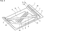
図4は、図1と異なるドアインパクトビームを有するドアインナーパネル及びドアインパクトビームの斜視図である。図4では、ドアインパクトビーム9が金属管からなる場合を示す。この場合、ドアインパクトビーム9は、ブラケット8を介してドアインナーパネル1に接合される。接合方法は、例えば、アーク溶接である。
FIG. 4 is a perspective view of a door inner panel having a door impact beam different from that in FIG. 1 and the door impact beam. FIG. 4 shows a case where the
ドアインパクトビーム9が金属板又は金属管のいずれの場合であっても、ドアインパクトビーム9の材料は鋼であるのが好ましい。強度等の調整、コスト等の観点からである。しかし、ドアインパクトビーム9の材料は鋼に限定されず、他の金属であってもよい。他の金属は、例えば、アルミニウム、アルミニウム合金、複層鋼、チタン、マグネシウム等である。金属以外としては、CFRP(炭素繊維強化プラスチック)や樹脂がある。また、ドアインパクトビーム9の引張強度は、1200MPa以上であるのが好ましい。側面衝突時の衝突エネルギを吸収し、搭乗者の安全を確保するためである。
Whether the
[ドアインナーパネル]
図4を参照して、本実施形態のドアインナーパネル1は金属板からなる。ドアインナーパネル1の材料である金属板は、例えば、鋼板、アルミニウム板、アルミニウム合金板、複層鋼板、チタン板、マグネシウム板等である。本実施形態では、金属板の板厚が一定である場合を説明する。したがって、ドアインナーパネル1の板厚も全域にわたり一定である。ただし、厳密には、プレス成形により、板厚のわずかな増減は生じる。
[Door inner panel]
With reference to FIG. 4, the door
天板部2の平面形状は多角形である。多角形は、たとえば、四角形でもよいし、五角形でもよい。多角形の角部は、R形状であってもよい。図4では、例として、天板部2の平面形状が五角形である場合を示す。ドアインナーパネル1において、天板部2の車両上側の辺はベルトラインBLを形成する。ベルトラインBLは図示しないウインドウの出入り口側になる。そのため、ベルトラインBLには縦壁部5は存在しない。
The planar shape of the top plate 2 is a polygon. The polygon may be, for example, a square or a pentagon. The corners of the polygon may be R-shaped. In FIG. 4, the case where the planar shape of the top plate part 2 is a pentagon is shown as an example. In the door
縦壁部5は、天板部2の外側の辺のうちの少なくとも2以上の各辺から伸びる。図4では、例として、天板部2の外側の5つの辺のうち、車両上側の辺(ベルトラインBL)を除く4つの辺2A、2B、2C及び2Dから縦壁部5が伸びる場合を示す。縦壁部5は、自動車の本体部品(ピラー、サイドシル等)と対向し、車内の密閉性を高める。そのため、縦壁部5は、天板部2の2以上の隣接する辺の各辺から伸びるのが好ましい。天板部2の2以上の隣接する各辺から縦壁部5が伸びる場合、各辺から伸びる各縦壁部も隣接する。図4では、例として、縦壁部5が天板部2に対して垂直に伸びる場合を示す。しかし、縦壁部5は天板部2に対して厳密に垂直でなくてもよい。
The vertical wall portion 5 extends from at least two sides of the outer side of the top plate portion 2. In FIG. 4, as an example, the case where the vertical wall 5 extends from four
段差部6は、天板部2に繋がる縦壁部5Aから外側に伸びる。段差部6の外縁は、フランジ部7に繋がる縦壁部5Bに繋がる。図4では、例として、段差部6が天板部2と平行である場合を示す。しかし、段差部6は、天板部2と厳密に平行でなくてもよい。図4では、例として、4つの隣接する縦壁部5が段差部6を有する場合を示す。すなわち、隣接する縦壁部5の組が3つあり、その3組が共に段差部6を有する場合を示す。また、図4では、1段の段差部6が縦壁部5に設けられる場合を示す。しかし、段差部6の数は1段に限定されず、複数段であってもよい。段差部6は、車体のピラーB等と対向し、車内を密閉する。車内の密閉性を高めるため、段差部6とピラー等との間にはシール部材が配置される。
The
図4では、ドアインナーパネル1が段差部6を有する場合を示す。しかし、ドアインナーパネル1は段差部6を有していなくてもよい。ドアインナーパネル1が段差部6を有していなくても車内の密閉性が十分に確保される場合、段差部6は不要である。ドアインナーパネル1が段差部6を有しない場合、ドアインパクトビーム9はドアインナーパネル1のフランジ部7に接合される。
FIG. 4 shows a case where the door
ドアインナーパネル1は開口部4を有していてもよい。開口部4には、スピーカ等の部品が取り付けられる。
The door
また、ドアインナーパネル1が鋼板からなる場合、鋼板はテーラードブランクでもよい。テーラードブランクは、テーラード溶接ブランク(以下、「TWB」ともいう)と、テーラードロールドブランク(以下、「TRB」ともいう)に大別される。TWBは、板厚、引張強度等が異なる複数種の鋼板を溶接(例:突き合わせ溶接)によって一体化したものである。一方、TRBは、鋼板を製造する際に圧延ロールの間隔を変更することによって、板厚を変化させたものである。テーラードブランクを用いると、必要な箇所に限定して強度を強化することができ、板厚を減少することもできる。また、テーラードブランクを用いたドアインナーパネルも自動車用のドアインナーパネルに適用できる。これにより、衝突特性を向上することができ、更に軽量化を望める。
Moreover, when the door
上述したように、本実施形態のドアインナーパネルは、ドアインパクトビームに与えられた衝突エネルギの一部を負担する。このため、ドアインナーパネルの強度は高い方が好ましい。具体的には、ドアインナーパネルの引張強度は、1200MPa以上である。引張強度の増加に伴って、ドアインナーパネルが衝突エネルギをより多く吸収できるからである。ただし、引張強度が高く、かつ、複雑な形状のドアインナーパネルは、通常、成形が困難である。具体的には、複雑な形状のドアインナーパネルは、加工中にシワ、割れ等が発生しやすい。複雑な形状はたとえば、図1に示すドアインナーパネル1のような隣接する縦壁部5が段差部6を有する形状等がある。以下、鋼板からなり、引張強度が1200MPa以上の複雑な形状のドアインナーパネルの製造方法の一例を説明する。
As described above, the door inner panel of this embodiment bears a part of the collision energy given to the door impact beam. For this reason, the strength of the door inner panel is preferably higher. Specifically, the tensile strength of the door inner panel is 1200 MPa or more. This is because the door inner panel can absorb more collision energy as the tensile strength increases. However, a door inner panel having a high tensile strength and a complicated shape is usually difficult to mold. Specifically, the door inner panel having a complicated shape is likely to be wrinkled or broken during processing. The complicated shape includes, for example, a shape in which adjacent vertical wall portions 5 have stepped
[製造方法]
本実施形態のドアインナーパネルの製造方法は、準備工程と、加熱工程と、ホットスタンピングによるプレス成形工程と、を備える。準備工程では鋼板からなるブランク材を準備する。加熱工程ではブランク材を加熱する。プレス成形工程では、加熱されたブランク材をプレス加工すると同時に、成形されたドアインナーパネルを焼入れする。本実施形態のプレス成形工程では、プレス加工装置として、ホットスタンピング装置を用いる。
[Production method]
The manufacturing method of the door inner panel of this embodiment includes a preparation process, a heating process, and a press molding process by hot stamping. In the preparation process, a blank made of a steel plate is prepared. In the heating process, the blank is heated. In the press molding process, the heated blank is pressed and simultaneously the molded door inner panel is quenched. In the press molding process of the present embodiment, a hot stamping device is used as a press working device.
[ホットスタンピング装置10]
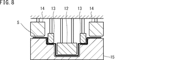
図5は、本実施形態のドアインナーパネルを製造するためのホットスタンピング装置を模式的に示す断面図である。図5を参照して、ホットスタンピング装置10は、上型として、パンチ11及びブランクホルダ14を備え、下型として、ダイ15を備える。
[Hot stamping device 10]
FIG. 5 is a cross-sectional view schematically showing a hot stamping device for manufacturing the door inner panel of the present embodiment. Referring to FIG. 5, the
パンチ11は、第1パンチ12と第2パンチ13とを備える。第1パンチ12には、ドアインナーパネルの天板部の形状が形成されている。第2パンチ13には、ドアインナーパネルの段差部の形状が形成されている。パンチ11は、ブランク材Sをダイ15に押し込みドアインナーパネルを成形する。
The
ブランクホルダ14は第2パンチ13の外側に配置される。ブランクホルダ14は、ダイ15と対向する。ブランクホルダ14は、ダイ15との間にブランク材Sを挟み込む。
The
ダイ15は、第1パンチ12及び第2パンチ13と対向する。
The die 15 faces the
ダイ15及び第1パンチ12は、図1に示すドアインナーパネル1の天板部2を成形する。ダイ15及び第2パンチ13は、図1に示すドアインナーパネル1の段差部6を成形する。ダイ15及びブランクホルダ14は、図1に示すドアインナーパネル1のフランジ部7を成形する。以下、本実施形態の製造方法の各工程を説明する。
The
[準備工程]
準備工程では、鋼板からなるブランク材を準備する。本実施形態のドアインナーパネルの鋼板は、質量%で、炭素(C):0.11%以上含有するのが好ましい。鋼板が0.11%以上の炭素を含有する場合、ホットスタンピング後のドアインナーパネルの強度を高くすることができる。
[Preparation process]
In the preparation step, a blank material made of a steel plate is prepared. The steel plate of the door inner panel of the present embodiment is preferably contained by mass% and carbon (C): 0.11% or more. When the steel plate contains 0.11% or more of carbon, the strength of the door inner panel after hot stamping can be increased.
[加熱工程]
加熱工程では、図示しない加熱装置によってブランク材は加熱される。ブランク材は、その材料のA1変態点以上に加熱されるのが好ましい。ブランク材はA3変態点以上に加熱されるのがさらに好ましい。ホットスタンピングでは、ブランク材をプレス成形するのと同時に、成形されたドアインナーパネルを焼入れする。ブランク材がA1点以上に加熱されれば、焼入れ後のドアインナーパネルの金属組織はマルテンサイトとなり強度が高くなる。加熱温度はたとえば、700〜900℃である。加熱温度は、材料、成形難易度等によって適宜設定される。ホットスタンピングでは、ブランク材を加熱し軟化させるため、複雑な形状を成形することができる。
[Heating process]
In the heating process, the blank is heated by a heating device (not shown). The blank material is preferably heated to the A1 transformation point or higher of the material. It is more preferable that the blank is heated to the A3 transformation point or higher. In hot stamping, the molded door inner panel is quenched at the same time as the blank material is press-molded. If the blank is heated to a point A1 or higher, the metal structure of the door inner panel after quenching becomes martensite and the strength is increased. The heating temperature is, for example, 700 to 900 ° C. The heating temperature is appropriately set depending on the material, the difficulty of molding, and the like. In hot stamping, the blank material is heated and softened, so that a complicated shape can be formed.
[プレス成形工程]
図6〜図8は、本実施形態のプレス成形工程を模式的に示す断面図である。図6はブランクホルダ14でブランク材Sを挟み込む段階を示す。図7は第2パンチ13による押し込みが完了したときの状態を示す。図8は第1パンチ12による押し込みが完了したときの状態を示す。
[Press forming process]
6-8 is sectional drawing which shows typically the press molding process of this embodiment. FIG. 6 shows a stage in which the blank material S is sandwiched by the
図6を参照して、加熱されたブランク材Sはホットスタンピング装置10に配置される。ブランク材Sが配置された後、ホットスタンピング装置のスライドが下降する。これにより、ブランクホルダ14とダイ15とでブランク材Sを挟み込む。ただし、ブランクホルダ14とダイ15との間隔は、ブランク材Sの厚さよりも大きい方が好ましい。すなわち、ブランク材Sとブランクホルダ14との間に隙間が設けられる。隙間の大きさはたとえば、0.1mmである。ブランク材Sをブランクホルダ14に接触させた場合、ブランク材Sがプレス成形される前に、ブランク材Sのブランクホルダ14と接触する部分が冷却される。そのため、ブランク材Sの冷却速度が部分的に異なるため、成形品の強度が部分により異なる。したがって、ブランクホルダ14とブランク材Sとの間にはわずかな隙間が設けられるのが好ましい。
With reference to FIG. 6, the heated blank S is placed in the
図7を参照して、スライドが更に下降すると、パンチ11とダイ15とによってブランク材Sは絞り成形される。図7では、第2パンチ13によるブランク材Sの押し込みが完了したとき、第1パンチ12は第2パンチ13と同じ高さの位置である場合を示す。すなわち、第2パンチ13によるブランク材Sの押し込みが完了したと同時に、第1パンチ12によるブランク材Sの押し込みが始まる場合を示す。
Referring to FIG. 7, when the slide is further lowered, blank material S is drawn by
しかしながら、第2パンチ13によるブランク材Sの押し込みが完了したとき、第1パンチ12の高さの位置は第2パンチ13と同じ高さの位置に限定されない。このときの第1パンチ12の高さの位置は、第2パンチ13よりも高い位置にあってもよいし、低い位置にあってもよい。すなわち、第2パンチ13によるブランク材Sの押し込みが完了した後に、第1パンチ12によるブランク材Sの押し込みが始まってもよい。また、第2パンチ13によるブランク材Sの押し込みが完了する前に、第1パンチ12によるブランク材Sの押し込みが始まってもよい。いずれの場合であっても、第1パンチ12による押し込みは、第2パンチ13による押し込みよりも先に完了しない。なお、ブランクホルダとダイによるブランク材の抑え込みは第2パンチの成形が完了するまでに行われればよい。
However, when the pressing of the blank material S by the
図8を参照して、第2パンチ13による押し込みが完了した後、第1パンチ12は下降し、ブランク材Sは絞り成形される。このとき、ブランク材Sの第2パンチ13により押し込まれた部分は、第2パンチ13により拘束される。これにより、ドアインナーパネルの段差部付近に発生するシワ等を抑制することができる。以下、この点を詳述する。
Referring to FIG. 8, after the pressing by the
[割れ及びシワの抑制]
図9は、一般的なホットスタンピング装置によるプレス加工中の状態を示す断面図である。図9では、一般的なホットスタンピング装置のダイの一部を拡大して示す。図9を参照して、ホットスタンピング装置200では、パンチ210は分割されていない。そのため、パンチ210を下降させたとき、ブランク材Sの一部分S1は、パンチ210及びダイ220によって拘束されていない。つまり、ブランク材Sの一部分S1は、パンチ210及びダイ220と接触しない。
[Suppression of cracks and wrinkles]
FIG. 9 is a cross-sectional view showing a state during press working by a general hot stamping apparatus. FIG. 9 shows an enlarged part of a die of a general hot stamping apparatus. Referring to FIG. 9, punch 210 is not divided in
ホットスタンピングでは、ブランク材とパンチ、ダイ等との接触によってブランク材を冷却する。したがって、プレス加工中の図9に示す段階では、ブランク材Sの一部分S1は、冷却されない。ブランク材Sの一部分S1は、パンチ210が図9に示す位置よりもさらに押し込まれたとき、冷却される。要するに、ドアインナーパネルの天板部及び段差部の形状が一体的に造形されたパンチ210によって、縦壁部に段差部が設けられたドアインナーパネルを成形した場合、ブランク材Sの一部分S1は他の部分よりも遅れて冷却される。
In hot stamping, the blank is cooled by contact between the blank and a punch, die, or the like. Therefore, in the stage shown in FIG. 9 during the press working, a part S1 of the blank S is not cooled. A part S1 of the blank S is cooled when the
ブランク材Sの冷却が部分的に遅れると、ブランク材Sの強度及び延性が部分的に異なる場合がある。この場合、成形されるドアインナーパネルにシワ等が発生しやすくなる。図1及び図4に示すように、ドアインナーパネル1の隣接する縦壁部5が段差部6を有する場合、特にシワ等が発生しやすい。成形後のドアインナーパネルの強度が高い場合、さらにシワ等が発生しやすくなる。
If the cooling of the blank material S is partially delayed, the strength and ductility of the blank material S may be partially different. In this case, wrinkles and the like are likely to occur on the molded door inner panel. As shown in FIG.1 and FIG.4, when the adjacent vertical wall part 5 of the door
本実施形態のドアインナーパネルの製造方法は、図5に示すように、第1パンチ12及び第2パンチ13を有するホットスタンピング装置10を用いる。これにより、図1及び図4に示すようなドアインナーパネル1の天板部2と段差部6は、別個のパンチで成形される。加えて、第2パンチ13による押し込みは、第1パンチ12による押し込みよりも先に完了する。これにより、一方のパンチが天板部2を成形するとき、他方のパンチがドアインナーパネル1の段差部6を抑え込む。したがって、天板部2を成形するとき、ブランク材の拘束されていない部分が少なくなり、ドアインナーパネルのシワ等を抑制することができる。
The door inner panel manufacturing method of this embodiment uses a
上述の説明では、本実施形態のドアが自動車用のサイドドアである場合について説明した。しかし、本実施形態のドアは、自動車用のサイドドアに限定されない。本実施形態のドアは、リアドア等にも適用できる。 In the above description, the case where the door of the present embodiment is a side door for an automobile has been described. However, the door of this embodiment is not limited to the side door for motor vehicles. The door of this embodiment can also be applied to a rear door or the like.
以上、本発明の実施形態を説明した。しかしながら、上述した実施形態は本発明を実施するための例示に過ぎない。したがって、本発明は上述した実施形態に限定されることなく、その趣旨を逸脱しない範囲内で上述した実施形態を適宜変更して実施することができる。 The embodiments of the present invention have been described above. However, the above-described embodiment is merely an example for carrying out the present invention. Therefore, the present invention is not limited to the above-described embodiment, and can be carried out by appropriately changing the above-described embodiment without departing from the spirit thereof.
1 ドアインナーパネル
2 天板部
3 凹部
4 開口部
5 縦壁部
6 段差部
7 フランジ部
8 ブラケット
9 ドアインパクトビーム
10 ホットスタンピング装置
12 第1パンチ
13 第2パンチ
14 ブランクホルダ
15 ダイ
16 ドアアウターパネル
17 ドアインパクトビームの両端部
18 陥没部
BL ベルトライン
S ブランク材
P 衝突荷重
θ 交差角
DESCRIPTION OF
Claims (6)
両端部が前記ドアインナーパネルに接合された1つのドアインパクトビームと、を備え、
前記ドアインナーパネルは、前記ドアインパクトビームと交差する直線状の凹部を含み、
前記凹部は前記ドアインパクトビームに向けて突出する、ドア。 A door inner panel made of a metal plate and having a tensile strength of 1200 MPa or more;
One door impact beam having both ends joined to the door inner panel,
The door inner panel includes a linear recess that intersects the door impact beam,
The recess is a door protruding toward the door impact beam.
前記凹部は前記ドアインパクトビームの中央で交差する、ドア。 The door according to claim 1,
The recess intersects at the center of the door impact beam.
前記凹部と前記ドアインパクトビームの交差角は、10°以上、90°以下である、ドア。 The door according to claim 1 or 2,
The intersection angle of the said recessed part and the said door impact beam is a door which is 10 degrees or more and 90 degrees or less.
前記ドアインパクトビームの全塑性曲げモーメントは、前記ドアインナーパネルの全塑性曲げモーメントよりも小さい、ドア。 The door according to any one of claims 1 to 3,
A door having a total plastic bending moment of the door impact beam smaller than a total plastic bending moment of the door inner panel.
前記ドアインパクトビームが、長手方向に延びる隆起部又は陥没部を含む、ドア。 The door according to any one of claims 1 to 4,
The door, wherein the door impact beam includes a ridge or depression extending in the longitudinal direction.
前記ドアインナーパネルは、多角形の天板部、前記天板部に形成された開口部、及び前記天板部の辺のうちの少なくとも2以上の隣接する辺から伸びる縦壁部、を有し、前記縦壁部のうちで隣接する縦壁部の組の少なくとも1組の各縦壁部は段差部を含む、ドア。
The door according to any one of claims 1 to 5,
The door inner panel has a polygonal top plate, an opening formed in the top plate, and a vertical wall extending from at least two adjacent sides of the top plate. The door in which at least one of the vertical wall portions of the vertical wall portions includes a step portion.
Priority Applications (1)
| Application Number | Priority Date | Filing Date | Title |
|---|---|---|---|
| JP2016063578A JP6634921B2 (en) | 2016-03-28 | 2016-03-28 | Doors for vehicles |
Applications Claiming Priority (1)
| Application Number | Priority Date | Filing Date | Title |
|---|---|---|---|
| JP2016063578A JP6634921B2 (en) | 2016-03-28 | 2016-03-28 | Doors for vehicles |
Publications (2)
| Publication Number | Publication Date |
|---|---|
| JP2017177841A true JP2017177841A (en) | 2017-10-05 |
| JP6634921B2 JP6634921B2 (en) | 2020-01-22 |
Family
ID=60008226
Family Applications (1)
| Application Number | Title | Priority Date | Filing Date |
|---|---|---|---|
| JP2016063578A Active JP6634921B2 (en) | 2016-03-28 | 2016-03-28 | Doors for vehicles |
Country Status (1)
| Country | Link |
|---|---|
| JP (1) | JP6634921B2 (en) |
Citations (5)
| Publication number | Priority date | Publication date | Assignee | Title |
|---|---|---|---|---|
| JP2004122961A (en) * | 2002-10-03 | 2004-04-22 | Mazda Motor Corp | Side door structure of vehicle |
| US20040124663A1 (en) * | 2002-11-12 | 2004-07-01 | Yi-Hwa Chu | Vehicle door side intrusion prevention assembly |
| JP2006282068A (en) * | 2005-04-01 | 2006-10-19 | Toyota Motor Corp | Door structure for vehicle |
| JP2009029366A (en) * | 2007-07-30 | 2009-02-12 | Kobe Steel Ltd | Automotive door with enhanced side impact performance |
| JP2011195107A (en) * | 2010-03-23 | 2011-10-06 | Honda Motor Co Ltd | Vehicle body side structure |
-
2016
- 2016-03-28 JP JP2016063578A patent/JP6634921B2/en active Active
Patent Citations (5)
| Publication number | Priority date | Publication date | Assignee | Title |
|---|---|---|---|---|
| JP2004122961A (en) * | 2002-10-03 | 2004-04-22 | Mazda Motor Corp | Side door structure of vehicle |
| US20040124663A1 (en) * | 2002-11-12 | 2004-07-01 | Yi-Hwa Chu | Vehicle door side intrusion prevention assembly |
| JP2006282068A (en) * | 2005-04-01 | 2006-10-19 | Toyota Motor Corp | Door structure for vehicle |
| JP2009029366A (en) * | 2007-07-30 | 2009-02-12 | Kobe Steel Ltd | Automotive door with enhanced side impact performance |
| JP2011195107A (en) * | 2010-03-23 | 2011-10-06 | Honda Motor Co Ltd | Vehicle body side structure |
Also Published As
| Publication number | Publication date |
|---|---|
| JP6634921B2 (en) | 2020-01-22 |
Similar Documents
| Publication | Publication Date | Title |
|---|---|---|
| JP6921909B2 (en) | Panel-shaped molded product | |
| JP5569661B2 (en) | Manufacturing method and manufacturing apparatus of press-molded body | |
| EP3485996B1 (en) | Hot-stamping formed article, structural member using the same, and manufacturing method of hot-stamping formed article | |
| US10265752B2 (en) | Method for manufacturing press-formed product and press-forming apparatus | |
| JP6206629B1 (en) | Door inner panel and door inner panel manufacturing method | |
| US11097789B2 (en) | Structural member for automobiles and method for producing the same | |
| JPWO2016194963A1 (en) | Press molded product, press molding method, and press molding apparatus | |
| US10124387B2 (en) | Press-molded product, press-molded product producing method, and press-molded product producing apparatus | |
| JP6743913B2 (en) | Structural member and structural member for vehicle | |
| US10682902B2 (en) | Panel-like formed product, vehicle door, and method for manufacturing a panel-like formed product | |
| US11534815B2 (en) | Press formed product, automobile structural member with the press formed product, and method for producing press formed product | |
| CA3034226C (en) | Automobile body press-molded component and method for producing same | |
| JP6634921B2 (en) | Doors for vehicles | |
| JP2018079779A (en) | Structural member for vehicle and manufacturing method therefor | |
| JP2014101094A (en) | Car body structure |
Legal Events
| Date | Code | Title | Description |
|---|---|---|---|
| A621 | Written request for application examination |
Free format text: JAPANESE INTERMEDIATE CODE: A621 Effective date: 20181105 |
|
| A131 | Notification of reasons for refusal |
Free format text: JAPANESE INTERMEDIATE CODE: A131 Effective date: 20190827 |
|
| A977 | Report on retrieval |
Free format text: JAPANESE INTERMEDIATE CODE: A971007 Effective date: 20190830 |
|
| A521 | Request for written amendment filed |
Free format text: JAPANESE INTERMEDIATE CODE: A523 Effective date: 20191024 |
|
| TRDD | Decision of grant or rejection written | ||
| A01 | Written decision to grant a patent or to grant a registration (utility model) |
Free format text: JAPANESE INTERMEDIATE CODE: A01 Effective date: 20191119 |
|
| A61 | First payment of annual fees (during grant procedure) |
Free format text: JAPANESE INTERMEDIATE CODE: A61 Effective date: 20191202 |
|
| R151 | Written notification of patent or utility model registration |
Ref document number: 6634921 Country of ref document: JP Free format text: JAPANESE INTERMEDIATE CODE: R151 |