JP2017174792A - Battery module - Google Patents
Battery module Download PDFInfo
- Publication number
- JP2017174792A JP2017174792A JP2016200715A JP2016200715A JP2017174792A JP 2017174792 A JP2017174792 A JP 2017174792A JP 2016200715 A JP2016200715 A JP 2016200715A JP 2016200715 A JP2016200715 A JP 2016200715A JP 2017174792 A JP2017174792 A JP 2017174792A
- Authority
- JP
- Japan
- Prior art keywords
- battery module
- battery
- opening
- case
- electrode
- Prior art date
- Legal status (The legal status is an assumption and is not a legal conclusion. Google has not performed a legal analysis and makes no representation as to the accuracy of the status listed.)
- Granted
Links
Images


Classifications
-
- H—ELECTRICITY
- H01—ELECTRIC ELEMENTS
- H01M—PROCESSES OR MEANS, e.g. BATTERIES, FOR THE DIRECT CONVERSION OF CHEMICAL ENERGY INTO ELECTRICAL ENERGY
- H01M50/00—Constructional details or processes of manufacture of the non-active parts of electrochemical cells other than fuel cells, e.g. hybrid cells
- H01M50/20—Mountings; Secondary casings or frames; Racks, modules or packs; Suspension devices; Shock absorbers; Transport or carrying devices; Holders
-
- B—PERFORMING OPERATIONS; TRANSPORTING
- B60—VEHICLES IN GENERAL
- B60L—PROPULSION OF ELECTRICALLY-PROPELLED VEHICLES; SUPPLYING ELECTRIC POWER FOR AUXILIARY EQUIPMENT OF ELECTRICALLY-PROPELLED VEHICLES; ELECTRODYNAMIC BRAKE SYSTEMS FOR VEHICLES IN GENERAL; MAGNETIC SUSPENSION OR LEVITATION FOR VEHICLES; MONITORING OPERATING VARIABLES OF ELECTRICALLY-PROPELLED VEHICLES; ELECTRIC SAFETY DEVICES FOR ELECTRICALLY-PROPELLED VEHICLES
- B60L50/00—Electric propulsion with power supplied within the vehicle
- B60L50/50—Electric propulsion with power supplied within the vehicle using propulsion power supplied by batteries or fuel cells
- B60L50/60—Electric propulsion with power supplied within the vehicle using propulsion power supplied by batteries or fuel cells using power supplied by batteries
- B60L50/64—Constructional details of batteries specially adapted for electric vehicles
-
- H—ELECTRICITY
- H01—ELECTRIC ELEMENTS
- H01M—PROCESSES OR MEANS, e.g. BATTERIES, FOR THE DIRECT CONVERSION OF CHEMICAL ENERGY INTO ELECTRICAL ENERGY
- H01M10/00—Secondary cells; Manufacture thereof
- H01M10/60—Heating or cooling; Temperature control
- H01M10/61—Types of temperature control
- H01M10/613—Cooling or keeping cold
-
- H—ELECTRICITY
- H01—ELECTRIC ELEMENTS
- H01M—PROCESSES OR MEANS, e.g. BATTERIES, FOR THE DIRECT CONVERSION OF CHEMICAL ENERGY INTO ELECTRICAL ENERGY
- H01M10/00—Secondary cells; Manufacture thereof
- H01M10/60—Heating or cooling; Temperature control
- H01M10/62—Heating or cooling; Temperature control specially adapted for specific applications
- H01M10/625—Vehicles
-
- H—ELECTRICITY
- H01—ELECTRIC ELEMENTS
- H01M—PROCESSES OR MEANS, e.g. BATTERIES, FOR THE DIRECT CONVERSION OF CHEMICAL ENERGY INTO ELECTRICAL ENERGY
- H01M10/00—Secondary cells; Manufacture thereof
- H01M10/60—Heating or cooling; Temperature control
- H01M10/64—Heating or cooling; Temperature control characterised by the shape of the cells
- H01M10/643—Cylindrical cells
-
- H—ELECTRICITY
- H01—ELECTRIC ELEMENTS
- H01M—PROCESSES OR MEANS, e.g. BATTERIES, FOR THE DIRECT CONVERSION OF CHEMICAL ENERGY INTO ELECTRICAL ENERGY
- H01M10/00—Secondary cells; Manufacture thereof
- H01M10/60—Heating or cooling; Temperature control
- H01M10/65—Means for temperature control structurally associated with the cells
- H01M10/655—Solid structures for heat exchange or heat conduction
- H01M10/6556—Solid parts with flow channel passages or pipes for heat exchange
-
- H—ELECTRICITY
- H01—ELECTRIC ELEMENTS
- H01M—PROCESSES OR MEANS, e.g. BATTERIES, FOR THE DIRECT CONVERSION OF CHEMICAL ENERGY INTO ELECTRICAL ENERGY
- H01M10/00—Secondary cells; Manufacture thereof
- H01M10/60—Heating or cooling; Temperature control
- H01M10/65—Means for temperature control structurally associated with the cells
- H01M10/656—Means for temperature control structurally associated with the cells characterised by the type of heat-exchange fluid
- H01M10/6567—Liquids
- H01M10/6568—Liquids characterised by flow circuits, e.g. loops, located externally to the cells or cell casings
-
- H—ELECTRICITY
- H01—ELECTRIC ELEMENTS
- H01M—PROCESSES OR MEANS, e.g. BATTERIES, FOR THE DIRECT CONVERSION OF CHEMICAL ENERGY INTO ELECTRICAL ENERGY
- H01M50/00—Constructional details or processes of manufacture of the non-active parts of electrochemical cells other than fuel cells, e.g. hybrid cells
- H01M50/20—Mountings; Secondary casings or frames; Racks, modules or packs; Suspension devices; Shock absorbers; Transport or carrying devices; Holders
- H01M50/204—Racks, modules or packs for multiple batteries or multiple cells
- H01M50/207—Racks, modules or packs for multiple batteries or multiple cells characterised by their shape
- H01M50/213—Racks, modules or packs for multiple batteries or multiple cells characterised by their shape adapted for cells having curved cross-section, e.g. round or elliptic
-
- H—ELECTRICITY
- H01—ELECTRIC ELEMENTS
- H01M—PROCESSES OR MEANS, e.g. BATTERIES, FOR THE DIRECT CONVERSION OF CHEMICAL ENERGY INTO ELECTRICAL ENERGY
- H01M50/00—Constructional details or processes of manufacture of the non-active parts of electrochemical cells other than fuel cells, e.g. hybrid cells
- H01M50/20—Mountings; Secondary casings or frames; Racks, modules or packs; Suspension devices; Shock absorbers; Transport or carrying devices; Holders
- H01M50/218—Mountings; Secondary casings or frames; Racks, modules or packs; Suspension devices; Shock absorbers; Transport or carrying devices; Holders characterised by the material
- H01M50/22—Mountings; Secondary casings or frames; Racks, modules or packs; Suspension devices; Shock absorbers; Transport or carrying devices; Holders characterised by the material of the casings or racks
- H01M50/227—Organic material
-
- H—ELECTRICITY
- H01—ELECTRIC ELEMENTS
- H01M—PROCESSES OR MEANS, e.g. BATTERIES, FOR THE DIRECT CONVERSION OF CHEMICAL ENERGY INTO ELECTRICAL ENERGY
- H01M50/00—Constructional details or processes of manufacture of the non-active parts of electrochemical cells other than fuel cells, e.g. hybrid cells
- H01M50/20—Mountings; Secondary casings or frames; Racks, modules or packs; Suspension devices; Shock absorbers; Transport or carrying devices; Holders
- H01M50/249—Mountings; Secondary casings or frames; Racks, modules or packs; Suspension devices; Shock absorbers; Transport or carrying devices; Holders specially adapted for aircraft or vehicles, e.g. cars or trains
-
- H—ELECTRICITY
- H01—ELECTRIC ELEMENTS
- H01M—PROCESSES OR MEANS, e.g. BATTERIES, FOR THE DIRECT CONVERSION OF CHEMICAL ENERGY INTO ELECTRICAL ENERGY
- H01M50/00—Constructional details or processes of manufacture of the non-active parts of electrochemical cells other than fuel cells, e.g. hybrid cells
- H01M50/20—Mountings; Secondary casings or frames; Racks, modules or packs; Suspension devices; Shock absorbers; Transport or carrying devices; Holders
- H01M50/258—Modular batteries; Casings provided with means for assembling
-
- H—ELECTRICITY
- H01—ELECTRIC ELEMENTS
- H01M—PROCESSES OR MEANS, e.g. BATTERIES, FOR THE DIRECT CONVERSION OF CHEMICAL ENERGY INTO ELECTRICAL ENERGY
- H01M50/00—Constructional details or processes of manufacture of the non-active parts of electrochemical cells other than fuel cells, e.g. hybrid cells
- H01M50/20—Mountings; Secondary casings or frames; Racks, modules or packs; Suspension devices; Shock absorbers; Transport or carrying devices; Holders
- H01M50/262—Mountings; Secondary casings or frames; Racks, modules or packs; Suspension devices; Shock absorbers; Transport or carrying devices; Holders with fastening means, e.g. locks
-
- H—ELECTRICITY
- H01—ELECTRIC ELEMENTS
- H01M—PROCESSES OR MEANS, e.g. BATTERIES, FOR THE DIRECT CONVERSION OF CHEMICAL ENERGY INTO ELECTRICAL ENERGY
- H01M50/00—Constructional details or processes of manufacture of the non-active parts of electrochemical cells other than fuel cells, e.g. hybrid cells
- H01M50/20—Mountings; Secondary casings or frames; Racks, modules or packs; Suspension devices; Shock absorbers; Transport or carrying devices; Holders
- H01M50/298—Mountings; Secondary casings or frames; Racks, modules or packs; Suspension devices; Shock absorbers; Transport or carrying devices; Holders characterised by the wiring of battery packs
-
- H—ELECTRICITY
- H01—ELECTRIC ELEMENTS
- H01M—PROCESSES OR MEANS, e.g. BATTERIES, FOR THE DIRECT CONVERSION OF CHEMICAL ENERGY INTO ELECTRICAL ENERGY
- H01M50/00—Constructional details or processes of manufacture of the non-active parts of electrochemical cells other than fuel cells, e.g. hybrid cells
- H01M50/50—Current conducting connections for cells or batteries
- H01M50/502—Interconnectors for connecting terminals of adjacent batteries; Interconnectors for connecting cells outside a battery casing
- H01M50/505—Interconnectors for connecting terminals of adjacent batteries; Interconnectors for connecting cells outside a battery casing comprising a single busbar
-
- H—ELECTRICITY
- H01—ELECTRIC ELEMENTS
- H01M—PROCESSES OR MEANS, e.g. BATTERIES, FOR THE DIRECT CONVERSION OF CHEMICAL ENERGY INTO ELECTRICAL ENERGY
- H01M50/00—Constructional details or processes of manufacture of the non-active parts of electrochemical cells other than fuel cells, e.g. hybrid cells
- H01M50/50—Current conducting connections for cells or batteries
- H01M50/502—Interconnectors for connecting terminals of adjacent batteries; Interconnectors for connecting cells outside a battery casing
- H01M50/507—Interconnectors for connecting terminals of adjacent batteries; Interconnectors for connecting cells outside a battery casing comprising an arrangement of two or more busbars within a container structure, e.g. busbar modules
-
- H—ELECTRICITY
- H01—ELECTRIC ELEMENTS
- H01M—PROCESSES OR MEANS, e.g. BATTERIES, FOR THE DIRECT CONVERSION OF CHEMICAL ENERGY INTO ELECTRICAL ENERGY
- H01M50/00—Constructional details or processes of manufacture of the non-active parts of electrochemical cells other than fuel cells, e.g. hybrid cells
- H01M50/50—Current conducting connections for cells or batteries
- H01M50/543—Terminals
- H01M50/547—Terminals characterised by the disposition of the terminals on the cells
- H01M50/548—Terminals characterised by the disposition of the terminals on the cells on opposite sides of the cell
-
- H—ELECTRICITY
- H01—ELECTRIC ELEMENTS
- H01M—PROCESSES OR MEANS, e.g. BATTERIES, FOR THE DIRECT CONVERSION OF CHEMICAL ENERGY INTO ELECTRICAL ENERGY
- H01M10/00—Secondary cells; Manufacture thereof
- H01M10/42—Methods or arrangements for servicing or maintenance of secondary cells or secondary half-cells
- H01M10/425—Structural combination with electronic components, e.g. electronic circuits integrated to the outside of the casing
- H01M2010/4271—Battery management systems including electronic circuits, e.g. control of current or voltage to keep battery in healthy state, cell balancing
-
- H—ELECTRICITY
- H01—ELECTRIC ELEMENTS
- H01M—PROCESSES OR MEANS, e.g. BATTERIES, FOR THE DIRECT CONVERSION OF CHEMICAL ENERGY INTO ELECTRICAL ENERGY
- H01M2220/00—Batteries for particular applications
- H01M2220/20—Batteries in motive systems, e.g. vehicle, ship, plane
-
- Y—GENERAL TAGGING OF NEW TECHNOLOGICAL DEVELOPMENTS; GENERAL TAGGING OF CROSS-SECTIONAL TECHNOLOGIES SPANNING OVER SEVERAL SECTIONS OF THE IPC; TECHNICAL SUBJECTS COVERED BY FORMER USPC CROSS-REFERENCE ART COLLECTIONS [XRACs] AND DIGESTS
- Y02—TECHNOLOGIES OR APPLICATIONS FOR MITIGATION OR ADAPTATION AGAINST CLIMATE CHANGE
- Y02E—REDUCTION OF GREENHOUSE GAS [GHG] EMISSIONS, RELATED TO ENERGY GENERATION, TRANSMISSION OR DISTRIBUTION
- Y02E60/00—Enabling technologies; Technologies with a potential or indirect contribution to GHG emissions mitigation
- Y02E60/10—Energy storage using batteries
-
- Y—GENERAL TAGGING OF NEW TECHNOLOGICAL DEVELOPMENTS; GENERAL TAGGING OF CROSS-SECTIONAL TECHNOLOGIES SPANNING OVER SEVERAL SECTIONS OF THE IPC; TECHNICAL SUBJECTS COVERED BY FORMER USPC CROSS-REFERENCE ART COLLECTIONS [XRACs] AND DIGESTS
- Y02—TECHNOLOGIES OR APPLICATIONS FOR MITIGATION OR ADAPTATION AGAINST CLIMATE CHANGE
- Y02T—CLIMATE CHANGE MITIGATION TECHNOLOGIES RELATED TO TRANSPORTATION
- Y02T10/00—Road transport of goods or passengers
- Y02T10/60—Other road transportation technologies with climate change mitigation effect
- Y02T10/70—Energy storage systems for electromobility, e.g. batteries
-
- Y—GENERAL TAGGING OF NEW TECHNOLOGICAL DEVELOPMENTS; GENERAL TAGGING OF CROSS-SECTIONAL TECHNOLOGIES SPANNING OVER SEVERAL SECTIONS OF THE IPC; TECHNICAL SUBJECTS COVERED BY FORMER USPC CROSS-REFERENCE ART COLLECTIONS [XRACs] AND DIGESTS
- Y02—TECHNOLOGIES OR APPLICATIONS FOR MITIGATION OR ADAPTATION AGAINST CLIMATE CHANGE
- Y02T—CLIMATE CHANGE MITIGATION TECHNOLOGIES RELATED TO TRANSPORTATION
- Y02T90/00—Enabling technologies or technologies with a potential or indirect contribution to GHG emissions mitigation
- Y02T90/10—Technologies relating to charging of electric vehicles
- Y02T90/16—Information or communication technologies improving the operation of electric vehicles
Abstract
Description
本発明は電池モジュールに関し、具体的には互いに接続することができる電池モジュールに関する。 The present invention relates to a battery module, and more specifically to a battery module that can be connected to each other.
一般の電池、特にリチウムイオン二次電池は、放電または充電の最中に発熱して温度が上がるため、電池が高温により劣化され、温度が高すぎると、電池が発煙、発火または破裂することが起こる可能性もある。従って、複数のリチウムイオン二次電池を同時に使用する時に、該複数のリチウムイオン二次電池を冷却するために、冷却システムを接続しながら使用する場合が多い。
冷却方法として、空冷、水冷などの冷却方法が挙げられる。空冷としては、例えば特許文献1に記載されている方法によれば、電池の外周面にヒートシンクを設置して、空気の流動により熱を発散する方法が挙げられている。水冷としては、例えば、複数の電池からなる電池シリーズを冷却液が流されている冷却槽に設置することにより、電池を冷却する方法が挙げられている。しかし、これらの冷却方法は、複数の電池を収容できる冷却槽を設置するための空間が大きいので、一部の電池設置空間が大きい装置以外利用できないという欠点がある。
General batteries, especially lithium-ion secondary batteries, generate heat during discharge or charge and the temperature rises, so the batteries are degraded by high temperatures, and if the temperature is too high, the batteries may smoke, ignite, or explode. It can happen. Therefore, when a plurality of lithium ion secondary batteries are used at the same time, in order to cool the plurality of lithium ion secondary batteries, the cooling system is often used while being connected.
Examples of the cooling method include cooling methods such as air cooling and water cooling. As air cooling, for example, according to the method described in
上記問題点に鑑みて、本発明は、各種の電池設置空間に設置できる電池モジュールを提供することを目的とする。 In view of the above problems, an object of the present invention is to provide a battery module that can be installed in various battery installation spaces.
上記目的を達成すべく、本発明は、少なくとも1つの電池ユニットから、正負両極端部がそれぞれ一つになるように配列されている電池シリーズと、前記電池シリーズを収容できる収容空間を画成するように構成されているケースと、を備えている電池モジュールであって、前記ケースは、第1の接続部と、前記正極端部の露出部分である第1の電極と、が形成されている第1の外表面と、他の電池モジュールの前記第1の接続部に嵌め合って接続できる第2の接続部と、前記負極端部の露出部分であって、前記第2の接続部が前記他の電池モジュールの前記第1の接続部と接続されると、前記他の電池モジュールの前記第1の電極に電気的に連接できるように構成されている第2の電極と、が形成されている第2の外表面と、からなっており、また、前記第1の外表面と前記第2の外表面とは、一つの電池モジュールの第2の接続部と他の電池モジュールの第1の接続部とを接続することを繰り返すことにより、前記電池モジュールを制限なく接続できる関係位置になっていることを特徴とする電池モジュールを提供する。 In order to achieve the above-mentioned object, the present invention defines a battery series arranged so that the positive and negative extreme parts are each one from at least one battery unit, and an accommodation space capable of accommodating the battery series. A battery module including a first connection portion and a first electrode that is an exposed portion of the positive electrode end portion. An outer surface of the first connection portion, a second connection portion that can be fitted and connected to the first connection portion of another battery module, and an exposed portion of the negative electrode end portion, the second connection portion being the other A second electrode configured to be electrically connected to the first electrode of the other battery module when connected to the first connection portion of the other battery module. And a second outer surface In addition, the first outer surface and the second outer surface are connected by repeatedly connecting the second connection part of one battery module and the first connection part of another battery module, Provided is a battery module, wherein the battery module is in a related position where the battery module can be connected without limitation.
上記構成により、本発明の電池モジュールは、一つの電池モジュールの第2の接続部と他の電池モジュールの第1の接続部を接続することを繰り返すことにより、前記電池モジュールを制限なく接続できるので、各装置の電池設置空間に合わせて組み立てることができて、従来の電池モジュールより多くの装置に適用できる。 With the above configuration, the battery module of the present invention can connect the battery modules without limitation by repeatedly connecting the second connection part of one battery module and the first connection part of another battery module. It can be assembled according to the battery installation space of each device, and can be applied to more devices than conventional battery modules.
<第1の実施形態>
以下、図1〜図3を参照しながら、本発明の第1の実施形態について詳しく説明する。
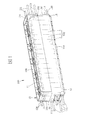
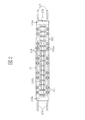
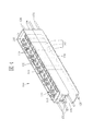
図1は本発明の第1の実施形態を示す斜面図であり、図2は上記電池モジュールを示す上視図であり、図3は上記電池モジュールを示す側面図である。
図1〜図3に示されるように、本発明の電池モジュール100は、少なくとも1つの電池ユニット1から、正負両極端部102a、102bがそれぞれ一つになるように配列されている電池シリーズ102と、電池シリーズ102を収容できる収容空間101を画成するように構成されているケース10と、を備えている。
ケース10は、第1の接続部108と、正極端部102aを露出部分とする第1の電極116と、が形成されている第1の外表面11と、収容空間101を介して第1の外表面11と相対すると共に、他の電池モジュール100の第1の接続部108に嵌め合って接続できる第2の接続部110と、負極端部102bを露出部分とし、第2の接続部110が他の電池モジュール100の第1の接続部108と接続されると、他の電池モジュール100の第1の電極116に電気的に連接できるように構成されている第2の電極122と、が形成されている第2の外表面12と、からなっている。
<First Embodiment>
Hereinafter, the first embodiment of the present invention will be described in detail with reference to FIGS.
FIG. 1 is a perspective view showing a first embodiment of the present invention, FIG. 2 is a top view showing the battery module, and FIG. 3 is a side view showing the battery module.
As shown in FIG. 1 to FIG. 3, the
The
また、第1の外表面11と第2の外表面12とは、一つの電池モジュールの第2の接続部110と他の電池モジュールの第1の接続部108とを接続することを繰り返すことにより、前記電池モジュールを制限なく接続できる関係位置になっている。
本発明の電池モジュール100の第1の実施形態において、図1に示されるように、ケース10は、分離して電池ユニット1を取り出すことができる上ケース体104及び下ケース体106により構成されて、第1の外表面11と第2の外表面12と第3の外表面13と第4の外表面14と第5の外表面15と第6の外表面16とを有する直方体に形成されている。
Moreover, the 1st
In the first embodiment of the
第1の外表面11及び第2の外表面12に加え、第3の外表面13及び第4の外表面14、第5の外表面15及び第6の外表面16の外表面のそれぞれも、ケース10において収容空間101を介して互いに相対するように位置している。第1の外表面11は上ケース体104に形成され、第2の外表面12は上述のように下ケース体106に形成されている。一方、第3の外表面及び第4の外表面、並びに第5の外表面及び第6の外表面は、上述した上ケース体104の外表面に加えて下ケース体106の外表面が一体となって形成される。
第1の接続部108と第2の接続部110とは、図示しない他の電池モジュールと接続する際に、それぞれ一方が他方に嵌め込まれるように嵌込型フランジ(female and male flanges)として機能する。
In addition to the first
The first connecting
図1及び図3に示すように、下ケース体106の第3の外表面13には、収容空間101と連通する第1の開口112が開けられ、上ケース体104の第4の外表面14には、収容空間101と連通する第2の開口114が開けられている。それにより、冷却液を第1の開口112及び第2の開口114を通じて収容空間101に出入りさせ、電池シリーズ102を冷却することができる。
また、開口の位置と数は、この実施形態に限られておらず、第1の開口112及び第2の開口114はいずれも下ケース体106に開けられても良く、第3の外表面13には、2つの第1の開口112が開けられることもできる。
As shown in FIGS. 1 and 3, the third
Further, the position and number of the openings are not limited to this embodiment, and both the
第1の開口112及び第2の開口114のそれぞれの周囲から、冷却液の流動経路とする冷却液分岐管(図示せず)が第1の開口112または第2の開口114に接続するように取り付けられる複数の連接棒124と、第3の外表面13及び第4の外表面14における開口が開けていない処から複数の固定棒126と、が突出している。
また、冷却液分岐管と第1の開口112または第2の開口114の間に、冷却液の漏れを防止するために、第1の開口112または第2の開口114の周縁に、シールリング(図示せず)を設置することができる。
A coolant branch pipe (not shown) serving as a coolant flow path is connected to the
Further, in order to prevent leakage of the coolant between the coolant branch pipe and the first opening 112 or the second opening 114, a seal ring (on the periphery of the
ケース10には、第1の外表面11と第2の外表面12との連接方向に沿うように形成されている第1のネジ孔(図示せず)と、前記第1のネジ孔に貫通されているネジ111と、を更に有する。
上ケース体104及び下ケース体106は、共に収容空間101を画成し、ネジ111が前記第1のネジ孔を貫通して上ケース体104及び下ケース体106を互いに接合するように固定することによりケース10に構成されている。
The
The
また、上ケース体104及び下ケース体106の接合方法は、この実施形態に限られておらず、例えば、接着剤で上ケース体104及び下ケース体106を粘着することや、溶接することで上ケース体104及び下ケース体106を接合することもできる。
また、上ケース体104及び下ケース体106の接合方法は、この実施形態に限られておらず、例えば、接着剤で粘着することや、溶接することで上ケース体104及び下ケース体106を接合することもできる。
Further, the method of joining the
Further, the method of joining the
ケース10の構成材料としては、例えば、ポリスチレン(PS:polystyrene)、ポリ塩化ビニル(PVC:polyvinyl chloride)、ポリカーボネート(PC:polycarbonate)、ポリエチレン(PE:polyethylene)、アクリル樹脂(acrylic)、プレキシガラス(PLEXIGLASS)、ポリカーボネート樹脂(LEXAN)、フェノール樹脂(phenolic resin)、液晶高分子(liquid crystal polymer)、PC/ABSアロイ(ABS-PC alloy)などが挙げられる。
Examples of the constituent material of the
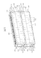
図4は上記電池モジュールを示す斜面図である。
電池シリーズ102は、図1及び図4に示されるように、複数の電池ユニット1からなっている。この実施形態において、電池シリーズ102は、電池モジュール100の長手方向に15個、短手方向に2個、合計30個の電池ユニット1からなっている。
FIG. 4 is a perspective view showing the battery module.
As shown in FIGS. 1 and 4, the
電池ユニット1としては、ニッケル・カドミウム蓄電池、ニッケル・水素充電池、リチウムイオン二次電池などが挙げられ、リチウムイオン二次電池としては、円筒形18650リチウムイオン電池などが挙げられる。
正負両極端部102a、102bにおける正極端部102aは、ケース10内における複数の電池ユニット1の1対1で隣り合って対になり且つ2列になるように並ぶ正極から、各対の前記正極同士がそれぞれ第1の外表面11の外からケース10内に挿入する複数の導電プレート118で連続される上、すべての複数の導電プレート118が更に第1の電極116で連続されることにより、電気的に一体に連続するようになっている。
Examples of the
The positive
また、負極端部102bは、ケース10内における複数の電池ユニットの1対1で隣り合って対になり且つ2列になるように並ぶ負極から、各対の前記負極同士がそれぞれ第2の外表面12の外からケース10内に挿入する複数の導電プレート118で連続される上、すべての複数の導電プレート118が更に第2の電極122で連続されることにより、電気的に一体に連続するようになっている。
すなわち、図2、図3、及び図4に示すように、電池ユニット1の正極端部102aは、ケース10内において短手方向に隣り合うもの同士が第1の外表面11の外側からケース10内に挿入される導電プレート118で接続されて対となる。また、長手方向に沿って2列に並べられたこれらの正極端部102aは、第1の電極116によって、導電プレート118を介して接続されることにより、電気的に一体的に接続される。
In addition, the negative
That is, as shown in FIGS. 2, 3, and 4, the positive
一方、電池ユニット1の負極端部102bについては底面図を省略しているが、正極端部102aの接続方法と同様に、ケース10内において短手方向に隣り合うもの同士が第2の外表面12の外側からケース10内に挿入される導電プレート118で接続されて対となり、且つ長手方向に沿って2列に並べられたこれらの負極電極102bは、第2の電極122によって、導電プレート118を介して接続されることにより、電気的に一体的に接続される。
On the other hand, although the bottom view of the negative
第1の電極116は、長さが第1の外表面11の幅の長さと同じ幅(若しくは嵌込型フランジの内側に嵌め込めるよう若干短い長さ)を有する2つの第1の先端部116aと、2つの第1の先端部116aを連接する第1の連接部116bと、を有している。
第2の電極122は、長さが第2の外表面12の幅の長さと同じ幅を有する2つの第2の先端部122aと、2つの第2の先端部122aを連接する第2の連接部122b、を有している。
The
The
第1の外表面11及び第2の外表面12は、導電プレート118を挿入するために複数の電池ユニットの正極または負極の位置に対応して開けられている複数の挿入口132を有している。挿入口132は、冷却液の漏れを防止するため、導電プレート118の挿入により水密になるように構成され、または、周縁のそれぞれにシールリングを設置することができる。
導電プレート118は、導電材料により構成され、短手方向に隣り合う電池ユニット1の正極または負極の間隔に対応して設置され、第1の連接部116bまたは第2の連接部122bを渡るように設置されて電気的に連接されている。
The first
The
なお、第1の電極116及び第2の電極122の構成材料としては、金属(銅、アルミニウム、ニッケル)、または、銅、アルミニウム、ニッケルの合金などが挙げられる。
導電プレート118の構成材料は、第1の電極116及び第2の電極122と同じ材料または相異する材料で構成することができる。
導電プレート118と第1の電極116または第2の電極122との接続方法としては、溶接、圧接、鍛接、ろう接、レーザービーム溶接、摩擦圧接、超音波溶接、ティグ溶接(tungsten inert gas welding、TIG welding)、ミグ溶接(metal inert gas welding、MIG welding)など導電プレート118と第1の電極116または第2の電極122とを電気的に連接できる接続方法を使用できる。なお、導電プレート118と第1の電極116または第2の電極122とを一体的に成形することもできる。
導電プレート118と第1の電極116または第2の電極122とを接続することにより、第1の電極116の連接部116bがすべての電池ユニット1の正極に電気的に連接し、第2の電極122の連接部122bがすべての電池ユニット1の負極に電気的に連接する。
Note that as a constituent material of the
The
The
By connecting the
なお、第3の外表面13には、図2及び図3に示されるように、第1の電極116の1つの先端部116aに連接している導電棒120が設置されることができる。
導電棒120は、図示しないバッテリーマネージメントシステム(battery management system)に電気的に連接して、電池モジュール10の温度や電圧などを計測することができる。また、導電棒120を防水機能を有するように構成することもできる。
As shown in FIGS. 2 and 3, the third
The
図5は2つの上記電池モジュールが接続されていることを示す斜視図である。2つの電池モジュール10の接続について、図5に示されるように、上の電池モジュール10の第2の接続部110と下の電池モジュール10の第1の接続部108とが接続されている。そして、ベルトまたはホルダーで2つの電池モジュール10の固定棒126を連接することができる。
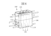
電池ユニットの数量及び配列方法は、この実施形態に限られておらず、例えば、図6及び図7に示されるように、6つの電池ユニットまたは12個の電池ユニットを1対1で隣り合って対になり且つ2列になるように並ぶことができる。また、3つの電池ユニットが第5の外表面15と第6の外表面16との連接方向に沿って並び、且つ3列になるように並ぶこともでき、必要に応じて適宜に変更することができる。
FIG. 5 is a perspective view showing that the two battery modules are connected. Regarding the connection of the two
The number and arrangement method of the battery units are not limited to this embodiment. For example, as shown in FIGS. 6 and 7, six battery units or twelve battery units are adjacent one-on-one. They can be arranged in pairs and in two rows. In addition, the three battery units can be arranged along the connecting direction of the fifth
この実施形態の構成によれば、本発明の電池モジュール100は、冷却槽として冷却液が流通できるように構成されているケース10を有すると共に、一つの電池モジュール100の第2の接続部110と他の電池モジュールの第1の接続部108とを接続することを繰り返すことにより、電池モジュール100を制限なく接続できるので、冷却機能を有すると同時に、各装置の電池設置空間に合わせて組み立てることができて、従来の電池モジュール100より多くの装置に適用できる。
According to the configuration of this embodiment, the
<第2の実施形態>
本発明の電池モジュールの第2の実施形態は、上記第1の実施形態とほぼ同じ構成を有するので、ここでは詳しい説明を省略し、その相違点のみを説明する。
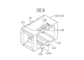
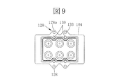
図8はこの実施形態における半分のケースを示す斜視図であり、図9は上記電池モジュール他の半分のケースを示す下視図である。
<Second Embodiment>
Since the second embodiment of the battery module of the present invention has substantially the same configuration as the first embodiment, detailed description thereof will be omitted here, and only the differences will be described.
FIG. 8 is a perspective view showing a half case in this embodiment, and FIG. 9 is a bottom view showing the other half case of the battery module.
本発明の電池モジュールの第2の実施形態において、図8及び図9に示されるように、第5の外表面15及び第6の外表面16には、それぞれ突起128と、他の電池モジュール170の突起128を嵌入できるように形成されている凹部131と、を有するように構成されている。
突起128は、上ケース体104の第5の外表面15及び第6の外表面16における周縁に形成されている第1の突起128aと、下ケース体106の第5の外表面15及び第6の外表面16における周縁に形成されている第2の突起128bと、により構成されている。上ケース体104と下ケース体106が接合されると、第1の突起128aと第2の突起128bとが1つの突起128になる。
In the second embodiment of the battery module of the present invention, as shown in FIGS. 8 and 9, the fifth
The
凹部131は、第2の突起128bの上ケース体104の前記周縁側の反対側で、第2の突起128bと隣接するように形成されている。
ケース10は、第1の外表面11と第2の外表面12との連接方向に沿って凹部131を経由するように形成されている第1のネジ孔130と、第1のネジ孔130に貫通されているネジ111と、を更に有している。突起128には、他の電池モジュール100の凹部131に嵌入すると、第1のネジ孔130と重なって、ネジ111を貫通できるように形成されている第2のネジ孔133、を有するように構成されている。
The
The
1つの電池モジュールの突起128を他の電池モジュールの凹部131に嵌入して接続する時に、先ず、該他の電池モジュールの上下を反転して、そして、該1つの電池モジュールの突起128を該他の電池モジュールの凹部131に嵌入すると共に、該他の電池モジュールの突起128が該1つの電池モジュールの凹部131に嵌入することになる。そして、ネジ111を第1のネジ孔130及び第2のネジ孔133を貫通して2つの電池モジュールの上ケース体104及び下ケース体106を互いに接合するように固定することにより2つの電池モジュールが接続されている。
When the
また、互いに接続されている2つの電池モジュールが1つの直方体を形成するように、上ケース体104のネジ111を貫通する方向における距離は、下ケース体106のそれより長く形成されている。
この実施形態の構成によれば、電池モジュールを第5の外表面15と第6の外表面16との連接方向に沿って繰り返して接続することができる。
Moreover, the distance in the direction which penetrates the screw |
According to the configuration of this embodiment, the battery module can be repeatedly connected along the connecting direction of the fifth
<第3の実施形態>
本発明の電池モジュール100の第3の実施形態は、上記第1の実施形態とほぼ同じ構成を有するので、ここでは詳しい説明を省略し、その相違点のみを説明する。
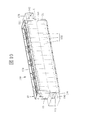
図10はこの実施形態を示す斜面図である。
本発明の電池モジュール100の第3の実施形態では、図10に示されるように、第3の外表面13に、第1の開口112の周縁から突出する上、第1の開口112が向かう方向と略直交して開口する第1の流通路180が形成されてなる第1の分岐管176を有している。
<Third Embodiment>
Since the third embodiment of the
FIG. 10 is a perspective view showing this embodiment.
In the third embodiment of the
第4の外表面14には、第2の開口114の周縁から突出する上、第1の流通路180と同様な第2の流通路182が形成されてなる第2の分岐管178を有している。
この実施形態の構成によれば、複数の電池モジュール100が、第5の外表面15と第6の外表面16との連接方向に沿って接続すると、複数の電池モジュールの各第1の分岐管176及び各第2の分岐管178が互いに連通されて、1つの分岐管となるので、冷却液が該分岐管を流通することができる。
また、第1の分岐管176または第2の分岐管178には、冷却システムに接続するための開口が開けられることもできる。
The fourth
According to the configuration of this embodiment, when the plurality of
The
<応用例1>
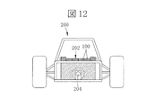
図11は上記第1の実施形態の電池モジュール100を電気自動車200に適用することを示す斜面図であり、図12は上記電気自動車の背面図である。
図11に示されるように、複数の第1の実施形態の電池モジュール100を上下に接続して、そして、図に示されていない冷却液分岐管またはホルダーで複数の上下に接続されている電池モジュールを水平方向に並ぶように固定して、1つの電池システム202になる。図12に示されるように、複数の電池モジュール100は、電気自動車200のシャフト204を包囲するように組み立てされている。
<Application example 1>
FIG. 11 is a perspective view showing application of the
As shown in FIG. 11, a plurality of
電気自動車200は、電力伝達システムを有している。該電力伝達システムは、450Vの出力密度を有する発動機と制御手段とを備えている。電池システム202は、450Vの電圧で33kWhの電力を提供できるように構成され、3240個の電池ユニットを含んでいて、30個1列で108列になる。また、電気自動車200は、冷却装置と充電装置とを設置することもでき、該冷却装置は、例えばヒートシンク及び冷却システムを有するものである。該充電装置は、例えばSAE J1772充電システムを使用するものである。
なお、電池システム202を複数のブロックに分けて、電気自動車200の電池設置空間に合わせて設置して、該複数のブロックを互いに電線で電気的に連接するように構成することもできる。
The
Note that the
<応用例2>
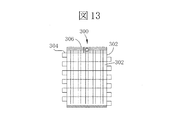
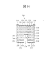
図13は複数の上記第2の実施形態の電池モジュール302からなった1つの電池システム300を示す側面図である。図14は上記電池システム300を示す側面図である。
電池システム300は、図13及び図14に示されるように、複数の水平分岐管304と、複数の電池キャップ306と、複数の連接手段308と、を更に有している。なお、電池システム300に、複数の水平分岐管304同士を連接する垂直分岐管を設置することもできる。
複数の水平分岐管304は、管路(図示せず)を介して冷却システム(熱交換器またはヒートシンク)に接続されている。
<Application example 2>
FIG. 13 is a side view showing one
As shown in FIGS. 13 and 14, the
The plurality of
図13及び図14に示されるように、複数の電池モジュール302が上下に接続されて1つの直列電池回路になる。電池システム300は、相隣する2つ該直列電池回路の正負極の位置が互いに反対となるように並んでいる10個の該直列電池回路により構成されている。該10個の直列電池回路は、複数の電池キャップ306により互いに直列に電気的に連接されている。連接手段308は、第1の電極116または第2の電極122と類似している電極を少なくとも1つを有し、該10個の直列電池回路の最上端の電池モジュール302同士と最下端の電池モジュール302同士を電気的に連接するように設置されている。なお、連接手段308で直列電池回路を並列に電気的に連接することもできる。
この電池システム300は、電池モジュール302及び連接手段308により、電池設置空間に合わせる間隔310を画成することができる。
As shown in FIGS. 13 and 14, a plurality of
The
電池キャップ306は、第1の電極116または第2の電極122と類似している電極を少なくとも1つを有し、複数の電池モジュール302を電気自動車の発動機または電力システムに電気的に連接するように設置されている。
すなわち、図14に示されるように、第1の電池キャップ306側(図14における左側)から開始し、複数の電池モジュールが上下方向に接続されて1列の直列電池回路を形成する。また、電池システム300は、図14において左右方向に相隣する直列電池回路の正極と負極の位置が互い違いとなるように配置されて、合計10列の該直列電池回路により構成されている。
ここで、図14の連接手段308は、上述した実施形態で説明した第1の電極116または第2の電極122と機能的に同様であるが、複数の連接手段308の間には絶縁体309(若しくは図示しない空隙)があるので、隣り合う連接手段308同士は電気的には絶縁されている。このようにして10列の電池モジュールは直列に接続されて、第1の電池キャップと第2の電池キャップ(図14における右側の電池キャップ306)側の電池モジュールは接続される。
The
That is, as shown in FIG. 14, starting from the
Here, the connecting means 308 in FIG. 14 is functionally similar to the
<応用例3>
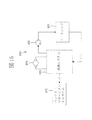
図15は上記電池システム402を使用する駆動手段400の回路を示す回路図である。駆動手段400は、電気自動車に使用されており、モーター404とポンプ406とヒートシンク408とを更に有している。電池システム402は主にモーター404に対して動力を提供する。モーター404は、交流電動機であるので、電池システム402からの直流電をインバータ(Inverter)などにより交流電に変換してから、モーター404に提供する。
ポンプ406とヒートシンク408とは、冷却液を電池システム402へ流通させて電池システム402の熱暴走(thermal runaway)を防止するために設置されている。該冷却液は、消火機能を有するものを使用することが好ましい。
電池システム402とポンプ406とヒートシンク408とは、閉ループ循環冷却システム(closed loop cooling system)に構成することができる。更に、該閉ループ循環冷却システムに、圧力を調整して冷却液の沸点を制御する二相冷却(two phase cooling)方法を使用することもできる。
<Application example 3>
FIG. 15 is a circuit diagram showing a circuit of the driving means 400 using the
The
The
なお、電池システム402をバッテリーマネージメントシステム401(battery management system)に電気的に連接して、電池モジュール10の温度や電圧などを計測することができる。
また、電池システム402は、他の電気自動車の装置に電力を提供することもできる。
Note that the
The
<応用例4>
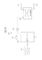
図16は上記電池システム402を使用するもう1つの駆動手段の回路を示す回路図である。
図16に示されるように、電池システム402は、電気推進船舶に使用されており、ポンプ406と熱交換器408’とを更に有している。
また、電池システム402をバッテリーマネージメントシステム401(battery management system)に電気的に連接して、電池モジュール10の温度や電圧などを計測することができる。
熱交換器408’は、湖水や海水を熱交換器408’の入口410及び出口412を通して熱交換器408’内に流通することにより冷却するように構成することができる。
電池システム402とポンプ406と熱交換器408’とは、開ループ循環冷却システム(open loop cooling system)に構成することができる。
<Application Example 4>
FIG. 16 is a circuit diagram showing a circuit of another driving means using the
As shown in FIG. 16, the
The
The
The
本発明の電池モジュールは、各電力を使用する装置に適用でき、更に電気自動車や電気推進船舶など電池を大量に使用して、電池を冷却することが必要な装置に好適である。 The battery module of the present invention can be applied to a device that uses each electric power, and is suitable for a device that needs to cool a battery by using a large amount of the battery such as an electric vehicle or an electric propulsion ship.
1 電池ユニット
10 ケース
11 第1の外表面
12 第2の外表面
13 第3の外表面
14 第4の外表面
15 第5の外表面
16 第6の外表面
100 電池モジュール
101 収容空間
102 電池シリーズ
102a 正極端部
102b 負極端部
104 上ケース体
106 下ケース体
108 第1の接続部
110 第2の接続部
111 ネジ
112 第1の開口
114 第2の開口
116 第1の電極
116a 第1の先端部
116b 第1の連接部
118 導電プレート
120 導電棒
122 第2の電極
122a 第2の先端部
122b 第2の連接部
124 連接棒
126 固定棒
128 突起
128a 第1の突起
128b 第2の突起
130 第1のネジ孔
131 凹部
132 挿入口
133 第2のネジ孔
176 第1の分岐管
178 第2の分岐管
180 第1の流通路
182 第2の流通路
200 電気自動車
202 電池システム
204 シャフト
300 電池システム
302 電池モジュール
304 水平分岐管
306 電池キャップ
308 連接手段
309 絶縁体
310 間隔
400 駆動手段
401 バッテリーマネージメントシステム
402 電池システム
404 モーター
406 ポンプ
408 ヒートシンク
408’ 熱交換器
410 入口
412 出口
DESCRIPTION OF
Claims (9)
前記電池シリーズを収容できる収容空間を画成するように構成されているケースと、
を備えている電池モジュールであって、
前記ケースは、
第1の接続部と、前記正極端部を露出部分とする第1の電極と、が形成されている第1の外表面と、
他の電池モジュールの前記第1の接続部に嵌め合って接続できる第2の接続部と、前記負極端部を露出部分とし、前記第2の接続部が前記他の電池モジュールの前記第1の接続部と接続されると、前記他の電池モジュールの前記第1の電極に電気的に連接できるように構成されている第2の電極と、が形成されている第2の外表面と、が形成され、
また、前記第1の外表面と前記第2の外表面とは、一つの電池モジュールの第2の接続部と他の電池モジュールの第1の接続部との接続を繰り返すことにより、前記電池モジュールを制限なく接続できる関係位置になっていることを特徴とする電池モジュール。 A battery series in which at least one battery unit is arranged so that the positive and negative extremes are each one; and
A case configured to define a storage space in which the battery series can be stored;
A battery module comprising:
The case is
A first outer surface on which a first connection portion and a first electrode having the positive electrode end portion as an exposed portion are formed;
A second connection portion that can be fitted and connected to the first connection portion of another battery module, and the negative electrode end portion is an exposed portion, and the second connection portion is the first connection portion of the other battery module. A second outer surface formed with a second electrode configured to be electrically connected to the first electrode of the other battery module when connected to the connection portion; Formed,
The first outer surface and the second outer surface may be formed by repeating the connection between the second connection portion of one battery module and the first connection portion of another battery module. A battery module characterized in that the battery module is in a relational position that can be connected without limitation.
前記第1の外表面と直交する面であって、前記ケースにおいて前記収容空間を介して互いに相対するように位置している第3の外表面及び第4の外表面を更に有しており、
前記第3の外表面には、前記収容空間と連通する第1の開口が開けられており、
前記第4の外表面には、前記収容空間と連通する第2の開口が開けられており、
前記第1の開口及び前記第2の開口を通じて冷却液を前記収容空間に出入りさせ、前記電池シリーズを冷却することができることを特徴とする請求項1または請求項2に記載の電池モジュール。 The first outer surface and the second outer surface are positioned so as to face each other through the housing space of the case,
A surface that is orthogonal to the first outer surface, and further includes a third outer surface and a fourth outer surface that are positioned so as to face each other through the accommodation space in the case;
The third outer surface has a first opening communicating with the accommodation space,
The fourth outer surface has a second opening that communicates with the accommodation space,
3. The battery module according to claim 1, wherein the battery series can be cooled by allowing a coolant to enter and leave the housing space through the first opening and the second opening. 4.
前記第4の外表面には、前記第2の開口の周縁から突出する上、前記第1の流通路と同様な第2の流通路が形成されてなる第2の分岐管を有していることを特徴とする請求項3に記載の電池モジュール。 A first branch formed on the third outer surface is formed with a first flow passage that protrudes from a peripheral edge of the first opening and opens substantially orthogonally to a direction toward the first opening. Has a tube,
The fourth outer surface has a second branch pipe that protrudes from the periphery of the second opening and is formed with a second flow path similar to the first flow path. The battery module according to claim 3.
前記正負両極端部における前記正極端部は、前記ケース内における前記複数の電池ユニットの1対1で隣り合って対になり且つ2列になるように並ぶ正極から、各対の前記正極同士がそれぞれ前記第1の外表面の外から前記ケース内に挿入する複数の導電プレートで連続される上、すべての前記複数の導電プレートが更に前記第1の電極で連続されることにより、電気的に一体に連続するようになっており、
前記正負両極端部における前記負極端部は、前記ケース内における前記複数の電池ユニットの1対1で隣り合って対になり且つ2列になるように並ぶ負極から、各対の前記負極同士がそれぞれ前記第2の外表面の外から前記ケース内に挿入する複数の導電プレートで連続される上、すべての前記複数の導電プレートが更に前記第2の電極で連続されることにより、電気的に一体に連続するようになっていることを特徴とする請求項1〜請求項5のいずれか一項に記載の電池モジュール。 The battery series consists of a plurality of battery units,
The positive electrode end portions in the positive and negative extreme portions are arranged in such a manner that the positive electrodes of each pair are adjacent to each other in a pair and in two rows in the case. The plurality of conductive plates inserted into the case from the outside of the first outer surface are continuous, and all the plurality of conductive plates are further continuous with the first electrode, thereby being electrically integrated. It is supposed to be continuous with
The negative electrode end portions in the positive and negative extreme portions are arranged in such a manner that the negative electrodes of each pair are adjacent to each other in pairs and in two rows in the case. A plurality of conductive plates inserted into the case from the outside of the second outer surface are continued, and all the plurality of conductive plates are further continued by the second electrode, thereby being electrically integrated. The battery module according to any one of claims 1 to 5, wherein the battery module is continuous with the battery module.
前記第5の外表面及び前記第6の外表面には、それぞれ突起と、前記他の電池モジュールの前記突起が嵌入できるように形成されている凹部と、を有するように構成されていることを特徴とする請求項3〜請求項5のいずれか一項に記載の電池モジュール。 The case further includes a fifth outer surface that is orthogonal to the first outer surface and the third outer surface, and a sixth outer surface that faces the fifth outer surface through the accommodating space. Have
Each of the fifth outer surface and the sixth outer surface has a protrusion and a recess formed so that the protrusion of the other battery module can be fitted therein. The battery module according to any one of claims 3 to 5, characterized in that:
前記突起には、前記他の電池モジュールの前記凹部に嵌入すると、前記第1のネジ孔と重なって、前記ネジが貫通できるように形成されている第2のネジ孔、を有するように構成されていることを特徴とする請求項7に記載の電池モジュール。 The case includes a first screw hole formed so as to pass through the recess along a connecting direction of the first outer surface and the second outer surface, and the first screw hole. A screw that is passed through,
The protrusion is configured to have a second screw hole formed so as to overlap the first screw hole and allow the screw to pass through when fitted into the recess of the other battery module. The battery module according to claim 7.
Applications Claiming Priority (2)
| Application Number | Priority Date | Filing Date | Title |
|---|---|---|---|
| US15/080,882 | 2016-03-25 | ||
| US15/080,882 US10784545B2 (en) | 2016-03-25 | 2016-03-25 | Submerged cell modular battery system |
Publications (2)
| Publication Number | Publication Date |
|---|---|
| JP2017174792A true JP2017174792A (en) | 2017-09-28 |
| JP6254658B2 JP6254658B2 (en) | 2017-12-27 |
Family
ID=56851487
Family Applications (1)
| Application Number | Title | Priority Date | Filing Date |
|---|---|---|---|
| JP2016200715A Active JP6254658B2 (en) | 2016-03-25 | 2016-10-12 | Battery module |
Country Status (6)
| Country | Link |
|---|---|
| US (1) | US10784545B2 (en) |
| EP (1) | EP3223338B1 (en) |
| JP (1) | JP6254658B2 (en) |
| KR (1) | KR101947235B1 (en) |
| CN (1) | CN107230750B (en) |
| TW (1) | TWI604653B (en) |
Cited By (5)
| Publication number | Priority date | Publication date | Assignee | Title |
|---|---|---|---|---|
| JP2020177910A (en) * | 2019-04-16 | 2020-10-29 | シン チン チー タオ クー フェン ユー シェン コン スー | Battery system |
| JP2021511642A (en) * | 2018-01-29 | 2021-05-06 | コミサリア ア エナジー アトミック エ オックス エナジーズ オルタネティヴ | Battery module and battery with multiple modules |
| JP2021511641A (en) * | 2018-01-29 | 2021-05-06 | コミサリア ア エナジー アトミック エ オックス エナジーズ オルタネティヴ | Storage battery module, and a battery with multiple modules |
| JP2022036027A (en) * | 2020-08-20 | 2022-03-04 | ドクター エンジニール ハー ツェー エフ ポルシェ アクチエンゲゼルシャフト | High-voltage battery, method for producing the same, and motor vehicle having battery of this type |
| WO2022163331A1 (en) | 2021-01-29 | 2022-08-04 | パナソニックIpマネジメント株式会社 | Ship propulsion device and battery temperature adjustment method |
Families Citing this family (30)
| Publication number | Priority date | Publication date | Assignee | Title |
|---|---|---|---|---|
| KR101391582B1 (en) * | 2013-06-05 | 2014-05-07 | (주)캡보이트레이딩 | Block and toy decoration cap |
| KR102085344B1 (en) * | 2016-10-24 | 2020-04-23 | 주식회사 엘지화학 | Battery pack for a vehicle and Vehicle including the same |
| US11135910B2 (en) * | 2017-06-25 | 2021-10-05 | Brp-Rotax Gmbh & Co. Kg | Electric kart and battery |
| DE102017217583A1 (en) | 2017-10-04 | 2019-04-04 | Siemens Aktiengesellschaft | Arrangement of battery cells and aircraft with such an arrangement |
| CN108232361B (en) * | 2017-12-28 | 2020-07-21 | 曙光节能技术(北京)股份有限公司 | Heat dissipation system of power battery pack and heat dissipation system of power battery |
| AT520928B1 (en) * | 2018-06-08 | 2019-09-15 | Raiffeisenlandesbank Oberoesterreich Ag | Temperature control device for individual, assembled into a module battery cells |
| DE102018119544B4 (en) * | 2018-08-10 | 2022-10-27 | Volkswagen Aktiengesellschaft | Battery module provided for driving a vehicle, arrangement of such a battery module on a further element and method for connecting such a battery module to a further element |
| TWI672890B (en) | 2018-08-31 | 2019-09-21 | 宏碁股份有限公司 | Battery unit and battery set |
| GB2577259B (en) * | 2018-09-18 | 2023-02-01 | Mclaren Automotive Ltd | Battery module coolant channels |
| CN113273016A (en) * | 2019-01-07 | 2021-08-17 | 卡诺科技公司 | Method and system for battery pack thermal management |
| CN109841918A (en) * | 2019-03-01 | 2019-06-04 | 华南理工大学 | Utilize the electric automobile power battery group radiator structure of the cooling heat dissipation of immersion |
| IT201900004721A1 (en) | 2019-03-29 | 2020-09-29 | Enrico Melotti | SCALABLE AND THERMOREGULABLE ELECTRIC POWER SYSTEM |
| US11742533B2 (en) * | 2019-04-18 | 2023-08-29 | Xing Power Inc. | Fluid-cooled battery system |
| US20220200082A1 (en) | 2019-05-16 | 2022-06-23 | 3M Innovative Properties Company | Space fillers for electrochemical cell packs |
| US11267354B2 (en) * | 2019-08-16 | 2022-03-08 | DESIGNWERK TECHNOLOGIES GmbH | Power supply |
| FR3102136B1 (en) * | 2019-10-22 | 2022-10-21 | Naval Group | VESSEL OF THE TYPE COMPRISING AT LEAST ONE ROOM IN WHICH ELECTRICAL MEANS ARE LOCATED |
| WO2021138699A1 (en) | 2020-01-05 | 2021-07-08 | Koolance, Inc. | Coolant reservoir and circulation assemblies and systems |
| WO2021144718A1 (en) | 2020-01-17 | 2021-07-22 | 3M Innovative Properties Company | Rapid venting of electrochemical cell packs |
| JP2023520456A (en) | 2020-03-30 | 2023-05-17 | シエル・インターナシヨネイル・リサーチ・マーチヤツピイ・ベー・ウイ | thermal management system |
| FR3115290B1 (en) | 2020-10-19 | 2023-11-17 | Arkema France | Thermal regulation of a battery by immersion in a liquid composition |
| FR3115287B1 (en) | 2020-10-19 | 2023-11-24 | Arkema France | Cooling of a battery by immersion in a composition with change of state |
| US20220294055A1 (en) * | 2021-03-10 | 2022-09-15 | Villara Corporation | Battery bank with unitary battery terminal connector straps |
| KR20230011608A (en) | 2021-07-14 | 2023-01-25 | 주식회사 스마트컴퍼니 | Battery pack of energy storage system |
| US11801866B2 (en) | 2021-09-29 | 2023-10-31 | Canoo Technologies Inc. | Emergency motion control for vehicle using steering and torque vectoring |
| US11845422B2 (en) | 2021-09-29 | 2023-12-19 | Canoo Technologies Inc. | Path tracking control for self-driving of vehicle with yaw moment distribution |
| US11845465B2 (en) | 2021-09-29 | 2023-12-19 | Canoo Technologies Inc. | Autonomous lateral control of vehicle using direct yaw moment control |
| DE102021127296B4 (en) | 2021-10-21 | 2023-05-11 | Dr. Ing. H.C. F. Porsche Aktiengesellschaft | Module for a high-voltage battery, use and manufacture of the same |
| DE102021005846A1 (en) * | 2021-11-24 | 2023-05-25 | e.battery systems GmbH | Cooling system for a battery unit and battery unit with such a cooling system |
| WO2023222677A1 (en) | 2022-05-19 | 2023-11-23 | Shell Internationale Research Maatschappij B.V. | Thermal management system |
| FR3140088A1 (en) | 2023-09-28 | 2024-03-29 | Arkema France | Cooling of a battery by immersion in a composition with change of state |
Citations (8)
| Publication number | Priority date | Publication date | Assignee | Title |
|---|---|---|---|---|
| EP1047139A1 (en) * | 1999-04-23 | 2000-10-25 | Oldham France S.A. | Direct current power supply for an electric motor vehicle |
| WO2011007533A1 (en) * | 2009-07-17 | 2011-01-20 | パナソニック株式会社 | Battery module and battery pack using the same |
| WO2012101728A1 (en) * | 2011-01-25 | 2012-08-02 | パナソニック株式会社 | Battery module and battery assembly used therein |
| WO2012101981A1 (en) * | 2011-01-25 | 2012-08-02 | パナソニック株式会社 | Battery module and battery assembly used therein |
| JP2013030384A (en) * | 2011-07-29 | 2013-02-07 | Panasonic Corp | Battery block and battery pack |
| WO2014038184A1 (en) * | 2012-09-05 | 2014-03-13 | パナソニック株式会社 | Battery module |
| JP2014110147A (en) * | 2012-11-30 | 2014-06-12 | Toyota Motor Corp | Power storage module and temperature adjustment structure for the same |
| US20150050538A1 (en) * | 2013-08-14 | 2015-02-19 | Samsung Sdi Co., Ltd. | Energy storage apparatus |
Family Cites Families (31)
| Publication number | Priority date | Publication date | Assignee | Title |
|---|---|---|---|---|
| JP4123541B2 (en) * | 1997-07-02 | 2008-07-23 | 株式会社デンソー | Battery cooling device |
| JP2001060466A (en) * | 1999-08-23 | 2001-03-06 | Japan Storage Battery Co Ltd | Set battery |
| JP3805664B2 (en) * | 2001-11-01 | 2006-08-02 | 株式会社マキタ | Battery pack |
| JP3649213B2 (en) * | 2002-07-30 | 2005-05-18 | 日産自動車株式会社 | Module battery |
| JP4739867B2 (en) * | 2005-08-31 | 2011-08-03 | 三洋電機株式会社 | Assembled battery |
| DE102007045183A1 (en) * | 2007-09-21 | 2009-04-02 | Robert Bosch Gmbh | Temperierte battery device and method for this purpose |
| JP2009117264A (en) * | 2007-11-09 | 2009-05-28 | Hitachi Ltd | Battery module |
| US8409743B2 (en) | 2007-11-28 | 2013-04-02 | Sanyo Electric Co., Ltd. | Battery system with battery cells arranged in array alignment |
| US8475954B2 (en) * | 2008-04-14 | 2013-07-02 | A123 Systems, LLC | Flexible voltage nested battery module design |
| US8563154B2 (en) * | 2009-05-06 | 2013-10-22 | GM Global Technology Operations LLC | Battery assembly with immersed cell temperature regulating |
| US8487631B2 (en) * | 2010-01-28 | 2013-07-16 | Panasonic Corporation | Battery module |
| US8383260B2 (en) | 2010-02-26 | 2013-02-26 | GM Global Technology Operations LLC | U-formed cooling plate with solid fins for lithium pouch cells |
| US20110223468A1 (en) * | 2010-03-15 | 2011-09-15 | Electronvault, Inc. | Variable Energy System |
| JP2012009388A (en) * | 2010-06-28 | 2012-01-12 | Hitachi Vehicle Energy Ltd | Battery pack |
| US8435668B2 (en) | 2010-07-23 | 2013-05-07 | GM Global Technology Operations LLC | Prismatic battery cell with integrated cooling passages and assembly frame |
| EP2636087A4 (en) * | 2010-11-05 | 2014-04-16 | Alelion Batteries Ab | Battery assembly |
| JP5578622B2 (en) * | 2011-02-17 | 2014-08-27 | シャープ株式会社 | Battery holding frame, power supply device and battery module |
| DE102011082562A1 (en) * | 2011-09-13 | 2013-03-14 | Sb Limotive Company Ltd. | Battery module e.g. lithium ion battery module for motor vehicle, has two coolant chambers that are provided in module housing in which coolant inlet and coolant outlet are provided |
| US8852772B2 (en) | 2011-11-15 | 2014-10-07 | GM Global Technology Operations LLC | Lithium ion battery cooling system comprising dielectric fluid |
| US8652672B2 (en) * | 2012-03-15 | 2014-02-18 | Aquion Energy, Inc. | Large format electrochemical energy storage device housing and module |
| KR101404336B1 (en) | 2012-07-06 | 2014-06-09 | 박환갑 | Wiring interconnect structure of heating unit for wet process of construction |
| JP2014060088A (en) * | 2012-09-19 | 2014-04-03 | Toshiba Corp | Secondary battery device and secondary battery system |
| DE102013200930A1 (en) * | 2013-01-22 | 2014-07-24 | Robert Bosch Gmbh | Device for mechanically coupling adjacent battery modules of modular battery, has connection elements arranged such that connection elements positively engage for coupling battery modules under normal arrangement |
| JP6199369B2 (en) * | 2013-02-14 | 2017-09-20 | 三洋電機株式会社 | Battery module |
| DE102013213550A1 (en) * | 2013-07-11 | 2015-01-15 | Robert Bosch Gmbh | Battery cell with a prismatic or cylindrical housing, battery module and motor vehicle |
| JP6216254B2 (en) * | 2014-01-28 | 2017-10-18 | ダイキョーニシカワ株式会社 | Battery module |
| KR101623251B1 (en) * | 2014-05-09 | 2016-05-20 | 에스케이이노베이션 주식회사 | Cooling system for battery module |
| DE102014106852A1 (en) * | 2014-05-15 | 2015-11-19 | Dr. Ing. H.C. F. Porsche Aktiengesellschaft | battery module |
| DE102014112626A1 (en) * | 2014-09-02 | 2016-03-03 | Dr. Ing. H.C. F. Porsche Aktiengesellschaft | Sealing element for sealing battery cells of a traction battery, molded body for producing the sealing element and method for producing the sealing element |
| CN104953060B (en) * | 2015-04-30 | 2017-06-27 | 中航光电科技股份有限公司 | Battery flat group |
| CN104993186B (en) * | 2015-06-29 | 2017-08-15 | 大连中比动力电池有限公司 | Battery modules |
-
2016
- 2016-03-25 US US15/080,882 patent/US10784545B2/en active Active
- 2016-07-21 TW TW105122982A patent/TWI604653B/en active
- 2016-08-09 CN CN201610645639.4A patent/CN107230750B/en active Active
- 2016-08-30 EP EP16186435.0A patent/EP3223338B1/en active Active
- 2016-10-12 JP JP2016200715A patent/JP6254658B2/en active Active
- 2016-10-26 KR KR1020160140140A patent/KR101947235B1/en active IP Right Grant
Patent Citations (8)
| Publication number | Priority date | Publication date | Assignee | Title |
|---|---|---|---|---|
| EP1047139A1 (en) * | 1999-04-23 | 2000-10-25 | Oldham France S.A. | Direct current power supply for an electric motor vehicle |
| WO2011007533A1 (en) * | 2009-07-17 | 2011-01-20 | パナソニック株式会社 | Battery module and battery pack using the same |
| WO2012101728A1 (en) * | 2011-01-25 | 2012-08-02 | パナソニック株式会社 | Battery module and battery assembly used therein |
| WO2012101981A1 (en) * | 2011-01-25 | 2012-08-02 | パナソニック株式会社 | Battery module and battery assembly used therein |
| JP2013030384A (en) * | 2011-07-29 | 2013-02-07 | Panasonic Corp | Battery block and battery pack |
| WO2014038184A1 (en) * | 2012-09-05 | 2014-03-13 | パナソニック株式会社 | Battery module |
| JP2014110147A (en) * | 2012-11-30 | 2014-06-12 | Toyota Motor Corp | Power storage module and temperature adjustment structure for the same |
| US20150050538A1 (en) * | 2013-08-14 | 2015-02-19 | Samsung Sdi Co., Ltd. | Energy storage apparatus |
Cited By (8)
| Publication number | Priority date | Publication date | Assignee | Title |
|---|---|---|---|---|
| JP2021511642A (en) * | 2018-01-29 | 2021-05-06 | コミサリア ア エナジー アトミック エ オックス エナジーズ オルタネティヴ | Battery module and battery with multiple modules |
| JP2021511641A (en) * | 2018-01-29 | 2021-05-06 | コミサリア ア エナジー アトミック エ オックス エナジーズ オルタネティヴ | Storage battery module, and a battery with multiple modules |
| JP2020177910A (en) * | 2019-04-16 | 2020-10-29 | シン チン チー タオ クー フェン ユー シェン コン スー | Battery system |
| JP7045729B2 (en) | 2019-04-16 | 2022-04-01 | シン チン チー タオ クー フェン ユー シェン コン スー | Battery system |
| JP2022036027A (en) * | 2020-08-20 | 2022-03-04 | ドクター エンジニール ハー ツェー エフ ポルシェ アクチエンゲゼルシャフト | High-voltage battery, method for producing the same, and motor vehicle having battery of this type |
| JP7397028B2 (en) | 2020-08-20 | 2023-12-12 | ドクター エンジニール ハー ツェー エフ ポルシェ アクチエンゲゼルシャフト | High-voltage battery, method of manufacturing it and motor vehicle with this kind of battery |
| US11909021B2 (en) | 2020-08-20 | 2024-02-20 | Dr. Ing. H.C. F. Porsche Aktiengesellschaft | High-voltage battery, method for producing same and motor vehicle having a battery of this type |
| WO2022163331A1 (en) | 2021-01-29 | 2022-08-04 | パナソニックIpマネジメント株式会社 | Ship propulsion device and battery temperature adjustment method |
Also Published As
| Publication number | Publication date |
|---|---|
| TWI604653B (en) | 2017-11-01 |
| EP3223338B1 (en) | 2022-05-11 |
| KR101947235B1 (en) | 2019-02-12 |
| US20170279172A1 (en) | 2017-09-28 |
| EP3223338A1 (en) | 2017-09-27 |
| US10784545B2 (en) | 2020-09-22 |
| KR20170112942A (en) | 2017-10-12 |
| JP6254658B2 (en) | 2017-12-27 |
| TW201735420A (en) | 2017-10-01 |
| CN107230750A (en) | 2017-10-03 |
| CN107230750B (en) | 2022-03-04 |
Similar Documents
| Publication | Publication Date | Title |
|---|---|---|
| JP6254658B2 (en) | Battery module | |
| JP6560446B2 (en) | Battery pack and automobile including the battery pack | |
| EP3361554B1 (en) | Battery module, battery pack comprising battery module, and vehicle comprising battery pack | |
| US9673490B2 (en) | Method and system for cooling secondary battery | |
| JP5613630B2 (en) | Power storage module | |
| JP6797301B2 (en) | Battery module | |
| EP3358668B1 (en) | Battery module, battery pack and vehicle having same | |
| JP2020520073A (en) | Cell edge direct cooling type battery module and battery pack including the same | |
| KR101608853B1 (en) | Frame for secondary battery and battery module including the same | |
| EP3379639B1 (en) | Battery module, battery pack comprising same, and vehicle | |
| KR102202417B1 (en) | The cartridge, Battery module including the cartridge, Battery pack | |
| KR102061292B1 (en) | Battery module, battery pack comprising the battery module and vehicle comprising the battery pack | |
| KR20180013460A (en) | Battery apparatus | |
| TWI765076B (en) | Battery packs and power batteries | |
| TW201721958A (en) | Battery cell assembly with improved cooling efficiency | |
| KR101853908B1 (en) | Battery module and battery pack including the same | |
| JP2012230775A (en) | Battery module | |
| TWM573900U (en) | Battery component and power battery | |
| US20140322580A1 (en) | Battery pack | |
| JP2024510432A (en) | Battery module containing insulating oil and battery pack containing the same | |
| KR20170043306A (en) | Battery module, battery pack comprising the battery module and vehicle comprising the battery pack |
Legal Events
| Date | Code | Title | Description |
|---|---|---|---|
| TRDD | Decision of grant or rejection written | ||
| A01 | Written decision to grant a patent or to grant a registration (utility model) |
Free format text: JAPANESE INTERMEDIATE CODE: A01 Effective date: 20171106 |
|
| A61 | First payment of annual fees (during grant procedure) |
Free format text: JAPANESE INTERMEDIATE CODE: A61 Effective date: 20171130 |
|
| R150 | Certificate of patent or registration of utility model |
Ref document number: 6254658 Country of ref document: JP Free format text: JAPANESE INTERMEDIATE CODE: R150 |
|
| S111 | Request for change of ownership or part of ownership |
Free format text: JAPANESE INTERMEDIATE CODE: R313113 |
|
| R350 | Written notification of registration of transfer |
Free format text: JAPANESE INTERMEDIATE CODE: R350 |
|
| R250 | Receipt of annual fees |
Free format text: JAPANESE INTERMEDIATE CODE: R250 |
|
| R250 | Receipt of annual fees |
Free format text: JAPANESE INTERMEDIATE CODE: R250 |
|
| R250 | Receipt of annual fees |
Free format text: JAPANESE INTERMEDIATE CODE: R250 |
|
| R250 | Receipt of annual fees |
Free format text: JAPANESE INTERMEDIATE CODE: R250 |