JP2017174573A - Luminaire - Google Patents
Luminaire Download PDFInfo
- Publication number
- JP2017174573A JP2017174573A JP2016057717A JP2016057717A JP2017174573A JP 2017174573 A JP2017174573 A JP 2017174573A JP 2016057717 A JP2016057717 A JP 2016057717A JP 2016057717 A JP2016057717 A JP 2016057717A JP 2017174573 A JP2017174573 A JP 2017174573A
- Authority
- JP
- Japan
- Prior art keywords
- outer lens
- exterior panel
- housing
- light source
- lighting device
- Prior art date
- Legal status (The legal status is an assumption and is not a legal conclusion. Google has not performed a legal analysis and makes no representation as to the accuracy of the status listed.)
- Granted
Links
- 239000000463 material Substances 0.000 claims abstract description 73
- 239000011347 resin Substances 0.000 claims abstract description 30
- 229920005989 resin Polymers 0.000 claims abstract description 30
- 238000000465 moulding Methods 0.000 claims abstract description 21
- 239000010409 thin film Substances 0.000 claims description 48
- 239000002184 metal Substances 0.000 claims description 47
- 229910052751 metal Inorganic materials 0.000 claims description 47
- 238000005286 illumination Methods 0.000 claims description 10
- 230000003796 beauty Effects 0.000 abstract description 9
- 230000002708 enhancing effect Effects 0.000 abstract 1
- 230000000694 effects Effects 0.000 description 15
- 238000000034 method Methods 0.000 description 15
- 230000002093 peripheral effect Effects 0.000 description 13
- 238000004519 manufacturing process Methods 0.000 description 9
- 239000000470 constituent Substances 0.000 description 8
- 238000007747 plating Methods 0.000 description 8
- 230000001771 impaired effect Effects 0.000 description 6
- 238000005240 physical vapour deposition Methods 0.000 description 6
- 238000001746 injection moulding Methods 0.000 description 5
- XECAHXYUAAWDEL-UHFFFAOYSA-N acrylonitrile butadiene styrene Chemical compound C=CC=C.C=CC#N.C=CC1=CC=CC=C1 XECAHXYUAAWDEL-UHFFFAOYSA-N 0.000 description 4
- 239000004676 acrylonitrile butadiene styrene Substances 0.000 description 4
- 229920000122 acrylonitrile butadiene styrene Polymers 0.000 description 4
- 239000003086 colorant Substances 0.000 description 4
- 238000002347 injection Methods 0.000 description 4
- 239000007924 injection Substances 0.000 description 4
- 239000004417 polycarbonate Substances 0.000 description 4
- 238000001579 optical reflectometry Methods 0.000 description 3
- 238000003466 welding Methods 0.000 description 3
- -1 PolyPropylene Polymers 0.000 description 2
- 239000004743 Polypropylene Substances 0.000 description 2
- 238000005401 electroluminescence Methods 0.000 description 2
- 229920003229 poly(methyl methacrylate) Polymers 0.000 description 2
- 229920000139 polyethylene terephthalate Polymers 0.000 description 2
- 239000005020 polyethylene terephthalate Substances 0.000 description 2
- 239000004926 polymethyl methacrylate Substances 0.000 description 2
- VYZAMTAEIAYCRO-UHFFFAOYSA-N Chromium Chemical compound [Cr] VYZAMTAEIAYCRO-UHFFFAOYSA-N 0.000 description 1
- BQCADISMDOOEFD-UHFFFAOYSA-N Silver Chemical compound [Ag] BQCADISMDOOEFD-UHFFFAOYSA-N 0.000 description 1
- ATJFFYVFTNAWJD-UHFFFAOYSA-N Tin Chemical compound [Sn] ATJFFYVFTNAWJD-UHFFFAOYSA-N 0.000 description 1
- 229920001923 acrylonitrile-ethylene-styrene Polymers 0.000 description 1
- 230000009194 climbing Effects 0.000 description 1
- 239000011248 coating agent Substances 0.000 description 1
- 238000000576 coating method Methods 0.000 description 1
- PNWJXICONNROSM-UHFFFAOYSA-N ethene;prop-2-enenitrile;styrene Chemical compound C=C.C=CC#N.C=CC1=CC=CC=C1 PNWJXICONNROSM-UHFFFAOYSA-N 0.000 description 1
- PCHJSUWPFVWCPO-UHFFFAOYSA-N gold Chemical compound [Au] PCHJSUWPFVWCPO-UHFFFAOYSA-N 0.000 description 1
- 229910052737 gold Inorganic materials 0.000 description 1
- 239000010931 gold Substances 0.000 description 1
- 238000009434 installation Methods 0.000 description 1
- 230000000873 masking effect Effects 0.000 description 1
- 239000007769 metal material Substances 0.000 description 1
- 238000012986 modification Methods 0.000 description 1
- 230000004048 modification Effects 0.000 description 1
- 229920000515 polycarbonate Polymers 0.000 description 1
- 229920001155 polypropylene Polymers 0.000 description 1
- QMRNDFMLWNAFQR-UHFFFAOYSA-N prop-2-enenitrile;prop-2-enoic acid;styrene Chemical compound C=CC#N.OC(=O)C=C.C=CC1=CC=CC=C1 QMRNDFMLWNAFQR-UHFFFAOYSA-N 0.000 description 1
- 239000004065 semiconductor Substances 0.000 description 1
- 229910052709 silver Inorganic materials 0.000 description 1
- 239000004332 silver Substances 0.000 description 1
- 229910052718 tin Inorganic materials 0.000 description 1
- 239000011135 tin Substances 0.000 description 1
Images


Landscapes
- Non-Portable Lighting Devices Or Systems Thereof (AREA)
Abstract
Description
本発明は照明装置に関するものである。 The present invention relates to a lighting device.
特許文献1には、光源の出射光を灯具前方へ向けて出射する柱状の導光体と、導光体の前方に配置されて凸部を有するレンズと、レンズとランプボディの接続部を隠蔽する前方部材とを備え、レンズの凸部が前方部材から露出する車両用灯具が開示されている。 In Patent Document 1, a columnar light guide that emits light emitted from a light source toward the front of the lamp, a lens that is disposed in front of the light guide and has a convex portion, and a connection between the lens and the lamp body are concealed. A vehicular lamp is disclosed in which a convex portion of the lens is exposed from the front member.
特許文献2には、透光性を有すると共にメッキ不可能な樹脂材料により目盛部を構成する透光性枠体と、透光性枠体の枠体表面及び目盛部側面を覆うようにメッキ可能な樹脂材料により透光性枠体と2色成形によって一体成形された金属調形成部と、金属調形成部の表面にメッキされたメッキ層とを備えた装飾リングが開示されている。 In Patent Document 2, a translucent frame that forms a scale portion with a resin material that is translucent and cannot be plated, and can be plated so as to cover the frame surface and the side of the scale portion of the translucent frame There is disclosed a decorative ring comprising a translucent frame and a metallic tone forming part integrally formed by two-color molding with a resin material, and a plating layer plated on the surface of the metallic tone forming part.
車両用の照明装置において、凹状のアウタレンズの底面部分を外装パネルの開口部から露出させるよう組み付けた場合、厚さの異なるアウタレンズの外周側壁部分が「たち面」として照明装置の前方側から目視可能であると、外周側壁の端面がアウタレンズに映り込んだり、アウタレンズの外周側壁とハウジングとの接合面が映り込むなどすることから、「たち面」の見栄えが悪いため、照明装置の美観が損なわれてしまう。
特許文献1の技術では、レンズの目視可能が部分が凸部になっており、且つ、レンズの側面が前方部材(外装パネル)により隠蔽されて照明装置の前方側から目視不可能なため、「たち面」が見えることによる美観の低下を回避することができる。
しかし、特許文献1の技術では、レンズの凸部と前方部材の開口部との公差を考慮して、レンズの凸部と前方部材の開口部とに隙間を設ける必要があり、その隙間の見栄えが悪く、レンズと前方部材の一体感を感じ難くなるため、美観が損なわれるという問題がある。
In a vehicle lighting device, when the bottom surface of the concave outer lens is assembled so as to be exposed from the opening of the exterior panel, the outer peripheral side wall portion of the outer lens having a different thickness can be viewed from the front side of the lighting device as a “front surface”. In this case, the end face of the outer peripheral side wall is reflected on the outer lens, or the joint surface between the outer peripheral side wall of the outer lens and the housing is reflected. End up.
In the technique of Patent Document 1, since the portion of the lens that is visible is a convex portion, and the side surface of the lens is concealed by the front member (exterior panel), it cannot be viewed from the front side of the lighting device. It is possible to avoid a decrease in aesthetics due to the “face”.
However, in the technique of Patent Document 1, it is necessary to provide a gap between the convex portion of the lens and the opening portion of the front member in consideration of the tolerance between the convex portion of the lens and the opening portion of the front member. However, since it is difficult to feel the unity between the lens and the front member, there is a problem that the beauty is impaired.
本発明は前記問題を解決するためになされたものであって、その目的は、外装パネルとアウタレンズの隙間を無くすことにより、見栄えを良くして美観を高めることが可能な照明装置を提供することにある。 The present invention has been made to solve the above problems, and an object of the present invention is to provide an illuminating device that can improve the appearance and enhance the appearance by eliminating the gap between the exterior panel and the outer lens. It is in.
本発明者らは前記課題を解決するために鋭意検討を重ねた結果、下記のように本発明の各局面に想到した。 As a result of intensive studies in order to solve the above-mentioned problems, the present inventors have arrived at each aspect of the present invention as follows.
<第1局面>
第1局面は、光源と、前記光源を収容するための第1部材および第2部材とを備えた照明装置であって、
前記第1部材は、樹脂材料から成る第1材料部および第2材料部の2色成形によって一体形成され、
前記第1材料部は前記第2部材に接合され、
前記第2材料部は前記光源の放射光を透過しない。
<First phase>
A first aspect is a lighting device including a light source, and a first member and a second member for housing the light source,
The first member is integrally formed by two-color molding of a first material portion and a second material portion made of a resin material,
The first material part is bonded to the second member;
The second material portion does not transmit the emitted light of the light source.
第1局面では、第1材料部および第2材料部は2色成形によって一体形成されているため、第1材料部を光源の放射光を透過するアウタレンズとし、第2材料部を外装パネルとした場合、外装パネルとアウタレンズが隙間無く密着した状態になるよう熱融着される。
外装パネルとアウタレンズに隙間があると、その隙間の見栄えが悪く、外装パネルとアウタレンズの一体感を感じ難くなるため、照明装置の美観が損なわれる。
それに対して、第1局面によれば、外装パネルとアウタレンズに隙間が無いため、照明装置の見栄えを良くして美観を高めることができる。
In the first aspect, since the first material portion and the second material portion are integrally formed by two-color molding, the first material portion is an outer lens that transmits the light emitted from the light source, and the second material portion is an exterior panel. In this case, the outer panel and the outer lens are heat-sealed so as to be in close contact with each other without a gap.
If there is a gap between the exterior panel and the outer lens, the appearance of the gap is poor, and it becomes difficult to feel a sense of unity between the exterior panel and the outer lens.
On the other hand, according to the first aspect, since there is no gap between the exterior panel and the outer lens, the appearance of the lighting device can be improved and the beauty can be enhanced.
または、第1材料部を光源が取付固定されたハウジングとし、第2材料部を外装パネルとし、第2部材を光源の放射光を透過するアウタレンズとし、ハウジングにおける外装パネルの開口部から露出された部分にアウタレンズが接合されている場合、ハウジングおよび外装パネルに対して、アウタレンズだけが別体であり、アウタレンズは外装パネルの開口部に嵌合されるため、外装パネルとアウタレンズの公差を小さくすることが可能であり、外装パネルとアウタレンズの隙間をも小さくすることができる。
外装パネルとアウタレンズに大きな隙間があると、その隙間の見栄えの悪さによって照明装置の美観が損なわれる。
それに対して、第1局面によれば、外装パネルとアウタレンズの隙間が小さいため、見栄えを良くして美観を高めることができる。
Alternatively, the first material portion is a housing to which a light source is attached and fixed, the second material portion is an exterior panel, and the second member is an outer lens that transmits light emitted from the light source, and is exposed from an opening of the exterior panel in the housing. When the outer lens is bonded to the part, only the outer lens is separate from the housing and the outer panel, and the outer lens is fitted into the opening of the outer panel, so that the tolerance between the outer panel and the outer lens is reduced. It is possible to reduce the gap between the exterior panel and the outer lens.
If there is a large gap between the exterior panel and the outer lens, the appearance of the lighting device is impaired due to the poor appearance of the gap.
On the other hand, according to the first aspect, since the gap between the exterior panel and the outer lens is small, the appearance can be improved and the beauty can be enhanced.
<第2局面>
第2局面は、第1局面において、
前記第1材料部は、前記光源の放射光を透過するアウタレンズであり、
前記第2材料部は外装パネルであり、
前記第2部材は、前記光源が取付固定されたハウジングであり、
前記アウタレンズにおける前記外装パネルの裏面から露出された部分に前記ハウジングが接合されている。
<Second phase>
The second aspect is the first aspect,
The first material part is an outer lens that transmits the emitted light of the light source,
The second material part is an exterior panel;
The second member is a housing to which the light source is attached and fixed.
The housing is joined to a portion of the outer lens exposed from the back surface of the exterior panel.
第2局面では、アウタレンズおよび外装パネルが2色成形によって一体形成されているため、照明装置の構成部品点数が、第1部材であるアウタレンズおよび外装パネルと、第2部材であるハウジングとの2点になる。
それに対して、アウタレンズと外装パネルとハウジングとを別個の部品にした場合、照明装置の構成部品点数は3点になる。
従って、第2局面によれば、アウタレンズと外装パネルとハウジングとを別個の部品にした場合に比べて、部品の組み立て工程が減るため製造コストを削減することができる。
In the second aspect, since the outer lens and the exterior panel are integrally formed by two-color molding, the number of component parts of the lighting device is two points: the outer lens and the exterior panel that are the first member, and the housing that is the second member. become.
On the other hand, when the outer lens, the exterior panel, and the housing are separate parts, the number of component parts of the lighting device is three.
Therefore, according to the second aspect, compared to the case where the outer lens, the exterior panel, and the housing are separate components, the assembly process of the components is reduced, so that the manufacturing cost can be reduced.
<第3局面>
第3局面は、第2局面において、前記アウタレンズと前記ハウジングの接合部分は、前記外装パネルの裏面側に配置されている。
第3局面では、アウタレンズとハウジングの接合部分が、外装パネルによって隠蔽され、照明装置の前方側からは視認不能になるため、その接合部分の見栄えの悪さによって照明装置の美観が損なわれるのを回避できる。
<Third phase>
According to a third aspect, in the second aspect, a joint portion between the outer lens and the housing is disposed on a back surface side of the exterior panel.
In the third aspect, since the joint portion between the outer lens and the housing is concealed by the exterior panel and is not visible from the front side of the lighting device, the appearance of the lighting device is prevented from being impaired due to the poor appearance of the joint portion. it can.
<第4局面>
第4局面は、第3局面において、前記アウタレンズの一部分が前記外装パネルの裏面に延出され、そのアウタレンズの延出された部分に前記ハウジングが接合されている。
第4局面では、アウタレンズにおける外装パネルの裏面に延出された部分により、アウタレンズと外装パネルの接触面積が増大するため、アウタレンズと外装パネルを強固に熱融着して固定することができる。
また、第4局面では、アウタレンズの延出された部分にハウジングが接合されているため、アウタレンズとハウジングの接合部分が外装パネルによって完全に隠蔽されることから、第3局面の前記作用・効果をより確実に得ることができる。
<4th phase>
According to a fourth aspect, in the third aspect, a part of the outer lens is extended to the back surface of the exterior panel, and the housing is joined to the extended part of the outer lens.
In the fourth aspect, the contact area between the outer lens and the exterior panel is increased by the portion of the outer lens that extends to the back surface of the exterior panel, so that the outer lens and the exterior panel can be firmly heat-sealed and fixed.
Further, in the fourth aspect, since the housing is joined to the extended part of the outer lens, the joined part of the outer lens and the housing is completely hidden by the exterior panel. It can be obtained more reliably.
<第5局面>
第5局面は、第2〜第4局面において、前記アウタレンズの表面は、前記外装パネルの表面から突出している。
第5局面では、めっき法またはPVD法を用いて外装パネルの表面に金属薄膜を形成した場合に、金属薄膜がアウタレンズの側面によって係止され、金属薄膜の端部がアウタレンズの表面まで延出されて乗り上げるのを防止することができる。
アウタレンズの表面に金属薄膜の端部が乗り上げると、その金属薄膜の端部がバリ状になるため、触れた人が怪我をするおそれがある上に、見栄えの悪さによって照明装置の美観が損なわれるという欠点があるが、第5局面によれば前記欠点を回避することができる。
<5th aspect>
In a fifth aspect, in the second to fourth aspects, the surface of the outer lens protrudes from the surface of the exterior panel.
In the fifth aspect, when a metal thin film is formed on the surface of the exterior panel using the plating method or the PVD method, the metal thin film is locked by the side surface of the outer lens, and the end of the metal thin film is extended to the surface of the outer lens. Can be prevented.
If the end of the metal thin film rides on the surface of the outer lens, the end of the metal thin film becomes burr-like, so that the person who touched it may be injured and the appearance of the lighting device is impaired due to poor appearance However, according to the fifth aspect, the above disadvantage can be avoided.
<第6局面>
第6局面は、第2〜第5局面において、前記アウタレンズの側面は、前記アウタレンズの表面から裾野状に広がるように傾斜するテーパー状に形成されている。
第6局面では、アウタレンズと外装パネルの接触面積が増大するため、アウタレンズと外装パネルを強固に熱融着して固定することができる。
<6th phase>
According to a sixth aspect, in the second to fifth aspects, the side surface of the outer lens is formed in a tapered shape that is inclined so as to spread from the surface of the outer lens in a skirt shape.
In the sixth aspect, since the contact area between the outer lens and the exterior panel increases, the outer lens and the exterior panel can be firmly heat-sealed and fixed.
<第7局面>
第7局面は、第6局面において、前記アウタレンズと前記ハウジングの接合部分は、前記アウタレンズのテーパー状の部分の裏面側に配置されている。
第7局面では、アウタレンズとハウジングの接合部分が外装パネルによって完全に隠蔽されることから、第3局面の前記作用・効果をより確実に得ることができる。
<Seventh aspect>
According to a seventh aspect, in the sixth aspect, a joint portion between the outer lens and the housing is disposed on a back surface side of a tapered portion of the outer lens.
In the seventh aspect, since the joint portion between the outer lens and the housing is completely concealed by the exterior panel, the action and effect of the third aspect can be obtained more reliably.
<第8局面>
第8局面は、第1局面において、
前記第1材料部は、前記光源が取付固定されたハウジングであり、
前記第2材料部は外装パネルであり、
前記第2部材は、前記光源の放射光を透過するアウタレンズであり、
前記ハウジングにおける前記外装パネルの開口部から露出された部分に前記アウタレンズが接合されている。
<Eighth aspect>
The eighth aspect is the first aspect,
The first material part is a housing to which the light source is attached and fixed,
The second material part is an exterior panel;
The second member is an outer lens that transmits the emitted light of the light source,
The outer lens is bonded to a portion of the housing exposed from the opening of the exterior panel.
第8局面では、ハウジングおよび外装パネルが2色成形によって一体形成されているため、照明装置の構成部品点数が、第1部材であるハウジングおよび外装パネルと、第2部材であるアウタレンズとの2点になることから、第2局面と同様の作用・効果を得ることができる。 In the eighth aspect, since the housing and the exterior panel are integrally formed by two-color molding, the number of component parts of the lighting device is two points: the housing and exterior panel as the first member, and the outer lens as the second member. Therefore, the same actions and effects as in the second aspect can be obtained.
<第9局面>
第9局面は、第1〜第8局面において、前記第2材料部の少なくとも表面に形成された金属薄膜を備える。
第9局面では、金属薄膜が光源の放射光を遮断するため、第2材料部に透明な樹脂材料を用いた場合でも、第2材料部が光源の放射光を透過しないようにすることができる。
また、第9局面では、金属薄膜の光沢や光反射性により、照明装置の美観を高めることができる。
<9th phase>
A ninth aspect includes a metal thin film formed on at least a surface of the second material portion in the first to eighth aspects.
In the ninth aspect, since the metal thin film blocks the emitted light of the light source, even when a transparent resin material is used for the second material portion, the second material portion can be prevented from transmitting the emitted light of the light source. .
In the ninth aspect, the beauty of the lighting device can be enhanced by the gloss and light reflectivity of the metal thin film.
<第10局面>
第10局面は、第9局面において、前記第1材料部は前記金属薄膜を形成困難な樹脂材料から成る。
第10局面では、めっき法またはPVD法を用いて第1部材に金属薄膜を形成した場合に、第1材料部に金属薄膜が形成されるのを防止して、第2材料部にのみ金属薄膜を形成することが可能になり、第9局面の前記作用・効果を確実に得ることができる。
<10th aspect>
A tenth aspect is the ninth aspect, wherein the first material portion is made of a resin material in which the metal thin film is difficult to form.
In the tenth aspect, when a metal thin film is formed on the first member using a plating method or a PVD method, the metal thin film is prevented from being formed on the first material portion, and only on the second material portion. Can be formed, and the action and effect of the ninth aspect can be obtained with certainty.
以下、本発明を具体化した各実施形態について図面を参照しながら説明する。尚、各実施形態において、同一の構成部材および構成要素については符号を等しくすると共に、同一内容の箇所については重複説明を省略する。
また、各図面では、説明を分かり易くするために、各実施形態の構成部材の寸法形状および配置箇所を誇張して模式的に図示してあり、各構成部材の寸法形状および配置箇所が実物とは必ずしも一致しないことがある。
Hereinafter, embodiments embodying the present invention will be described with reference to the drawings. In each embodiment, the same constituent members and constituent elements are denoted by the same reference numerals, and redundant description of the same contents is omitted.
Moreover, in each drawing, in order to make the explanation easy to understand, the dimensional shape and arrangement location of the constituent members of each embodiment are schematically illustrated in an exaggerated manner, and the dimensional shape and arrangement location of each constituent member are the real thing. May not always match.
<第1実施形態>
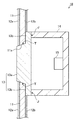
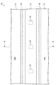
図1および図2に示すように、第1実施形態の照明装置10は、外装パネル11(貫通孔11a)、金属薄膜12a,12b、アウタレンズ13(凸部13a、フランジ部13b)、ハウジング14、光源15、接合部分J、テーパー状部分Tなどを備え、車両外装用照明装置(例えば、フォグランプなど)として用いられる。
<First Embodiment>
As shown in FIGS. 1 and 2, the
外装パネル11は長尺板状で貫通孔11aを備え、外装パネル11の表面(前面)には金属薄膜12aが形成され、外装パネル11の裏面(背面)には金属薄膜12bが形成されている。
アウタレンズ13は凸部13aおよびフランジ部13bを備え、外装パネル11と2色成形(ダブルモールド、異材質成形)によって一体形成されている。
凸部13aの表面は平坦状であり、凸部13aの側面には鍔状のフランジ部13bが突設され、凸部13aの側面は凸部13aの表面に対して鈍角を成して裾野状に広がるように傾斜する線形テーパー状に形成され、フランジ部13bの裏面はアウタレンズ13の平坦な裏面と面一になっている。
The
The
The surface of the
アウタレンズ13の凸部13aは外装パネル11の貫通孔11aに嵌合され、凸部13aの表面は外装パネル11の表面から僅かに突出し、アウタレンズ13のフランジ部13bは外装パネル11の裏面に当接して延出され、フランジ部13bを含むアウタレンズ13の裏面は外装パネル11の裏面から露出されている。
金属薄膜12bは、外装パネル11の裏面におけるアウタレンズ13のフランジ部13bから露出した部分に形成されている。
The
The metal
ハウジング14は前面側が開口された長尺箱状であり、ハウジング14の底面には複数個の光源15が取付固定されている。
複数個の光源15は、アウタレンズ13の凸部13aと対向する箇所にて、照明装置10の長手方向に間隔を空けて配置されている。
各光源15の放射光は、アウタレンズ13の凸部13aを通し、照明装置10の長手方向に沿ってその前方側に照射される。
The
The plurality of
The emitted light of each
ハウジング14の外周側壁の先端部分は、アウタレンズ13のフランジ部13bの裏面に溶着または接着により接合固定されている。
ハウジング14の開口部をアウタレンズ13により完全に閉塞して液密構造にすれば、光源15を雨水から保護して照明装置10の信頼性を高めることができる。
The front end portion of the outer peripheral side wall of the
If the opening of the
[照明装置10の構成部材]
外装パネル11は、アウタレンズ13と2色成形可能で、金属薄膜12a,12bを形成可能な樹脂材料から成り、その樹脂材料には、例えば、ABS(Acrylonitrile Butadiene Styrene)、PP(PolyPropylene)、AES(Acrylonitrile Ethylene Styrene)、ASA(Acrylate Styrene Acrylonitrile)などがある。
外装パネル11の樹脂材料のうち、ABSは安価で易めっき性であり射出成形性に優れて剛性が高いため最も好適である。
[Constituent Member of Lighting Device 10]
The
Of the resin materials for the
金属薄膜12a,12bは、めっき法またはPVD(Physical Vapor Deposition)法によって形成された金属材料(例えば、スズ、銀、金、クロムなど)の光反射性薄膜から成る。
The metal
アウタレンズ13は、外装パネル11と2色成形可能であると共に、その表面に金属薄膜12a,12bを形成困難であり、十分な透光性を有する樹脂材料から成り、その樹脂材料には、例えば、PC(Polycarbonate)、PMMA(Polymethyl methacrylate)、PET(Polyethylene Terephthalate)などがある。
アウタレンズ13の樹脂材料のうち、PCは安価で射出成形性および耐候性に優れて透明度が高く難めっき性であるため最も好適である。
The
Of the resin materials for the
ハウジング14は、アウタレンズ13と溶着または接着が可能な樹脂材料から成り、射出成形により一体形成されている。
光源15は十分な光量が得られるならばどのような光源を用いてもよく、その光源には、例えば、半導体発光素子(例えば、LED(Light Emitting Diode)チップ、EL(Electro Luminescence)チップ、LD(Laser Diode)チップなど)、電球、蛍光灯などがある。
The
The
[照明装置10の製造方法]
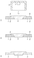
まず、図3(A)に示すように、外装パネル11およびアウタレンズ13を2色成形によって一体形成する。
すなわち、2色成形では一台の射出成形機を用い、一次金型と共通金型を型締めして一次側成形品のアウタレンズ13を射出成形した後に一次金型のみを取り外し、共通金型にアウタレンズ13を残した状態で二次金型と共通金型を型締めして二次側成形品の外装パネル11を射出成形することにより、異なる樹脂材料から成る外装パネル11とアウタレンズ13が隙間無く密着した状態になるよう熱融着させる。
[Manufacturing Method of Lighting Device 10]
First, as shown in FIG. 3A, the
That is, in the two-color molding, a single injection molding machine is used, the primary mold and the common mold are clamped and the
2色成形によれば、外装パネル11とアウタレンズ13を別々に射出成形した後に組み立てる場合に比べて、組み立て工程が不要であるため製造コストを削減することができる。
また、2色成形によれば、先に射出成形しておいたアウタレンズ13を、外装パネル11の射出成形時にインサート成形する場合に比べて、アウタレンズ13の変形や破損を防止した上で、外装パネル11とアウタレンズ13との密着度を高めて確実に一体形成できることに加え、射出成形の工程が1回で済むため製造コストを削減することができる。
According to the two-color molding, as compared with the case where the
Also, according to the two-color molding, the
次に、図3(B)に示すように、アウタレンズ13から露出している外装パネル11の表裏面に、めっき法を用いて金属薄膜12a,12bを形成する。
ここで、アウタレンズ13の樹脂材料を難めっき性のPCにし、外装パネル11の樹脂材料を易めっき性のABSにすれば、マスクなどを用いることなく、外装パネル11の表裏面のみに金属薄膜12a,12bを形成することができる。
続いて、図3(C)に示すように、光源15が取付固定されたハウジング14をアウタレンズ13に取付固定すれば、照明装置10が完成する。
Next, as shown in FIG. 3B, metal
Here, if the resin material of the
Subsequently, as shown in FIG. 3C, when the
[第1実施形態の作用・効果]
第1実施形態の照明装置10によれば、以下の作用・効果を得ることができる。
[Operations and effects of the first embodiment]
According to the
[1−1]照明装置10では、アウタレンズ13(第1材料部)および外装パネル11(第2材料部)が2色成形によって一体形成されているため、外装パネル11とアウタレンズ13が隙間無く密着した状態になるよう熱融着される。
外装パネル11とアウタレンズ13に隙間があると、その隙間の見栄えが悪く、外装パネル11とアウタレンズ13の一体感を感じ難くなるため、照明装置10の美観が損なわれる。
それに対して、照明装置10では、外装パネル11とアウタレンズ13に隙間が無いため、見栄えを良くして美観を高めることができる。
[1-1] In the
If there is a gap between the
On the other hand, in the illuminating
[1−2]外装パネル11およびアウタレンズ13が2色成形によって一体形成されているため、照明装置10の構成部品点数が、外装パネル11およびアウタレンズ13(第1部材)と、ハウジング14(第2部材)との2点になる。
それに対して、外装パネル11とアウタレンズ13とハウジング14とを別個の部品にした場合、照明装置の構成部品点数は3点になる。
従って、照明装置10によれば、アウタレンズ13と外装パネル11とハウジング14とを別個の部品にした場合に比べて、部品の組み立て工程が減るため製造コストを削減することができる。
[1-2] Since the
On the other hand, when the
Therefore, according to the illuminating
[1−3]図1に示すように、アウタレンズ13とハウジング14の接合部分Jは、外装パネル11の裏面側に配置されているため、接合部分Jが外装パネル11によって隠蔽され、照明装置10の前方側からは接合部分Jが視認不能になるため、接合部分Jの見栄えの悪さによって照明装置10の美観が損なわれるのを回避できる。
[1-3] As shown in FIG. 1, the joint portion J between the
[1−4]アウタレンズ13の一部分であるフランジ部13bが外装パネル11の裏面に延出され、フランジ部13bの裏面にハウジング14が接合されており、フランジ部13bによりアウタレンズ13と外装パネル11の接触面積が増大するため、アウタレンズ13と外装パネル11を強固に熱融着して固定することができる。
また、図1に示すように、フランジ部13bの裏面にハウジング14が接合されているため、アウタレンズ13とハウジング14の接合部分Jが外装パネル11によって完全に隠蔽されることから、前記[1−3]の作用・効果をより確実に得ることができる。
[1-4] A
Further, as shown in FIG. 1, since the
[1−5]アウタレンズ13の凸部13aは外装パネル11の表面から突出しているため、外装パネル11の表面に形成された金属薄膜12aは、凸部13aの側面によって係止され、金属薄膜12aの端部がアウタレンズ13の表面まで延出されて乗り上げるのを防止することができる。
アウタレンズ13の表面に金属薄膜12aの端部が乗り上げると、金属薄膜12aの端部がバリ状になるため、触れた人が怪我をするおそれがある上に、見栄えの悪さによって照明装置10の美観が損なわれるという欠点があるが、照明装置10によれば前記欠点を回避することができる。
[1-5] Since the
If the end of the metal
[1−6]アウタレンズ13の凸部13aの側面は、凸部13aの表面に対して鈍角を成して裾野状に広がるように傾斜する線形テーパー状に形成されているため、アウタレンズ13と外装パネル11の接触面積が増大することから、アウタレンズ13と外装パネル11を強固に熱融着して固定することができる。
[1-6] Since the side surface of the
[1−7]外装パネル11の表面に形成された金属薄膜12aが光源15の放射光を遮断するため、外装パネル11に透明な樹脂材料を用いた場合でも、外装パネル11が光源15の放射光を透過しないようにすることができる。
また、金属薄膜12aの光沢や光反射性により、照明装置10の美観を高めることができる。
[1-7] Since the metal
Moreover, the beauty | look of the illuminating
尚、めっき法またはPVD法によって金属薄膜を形成する際には、外装パネル11の表裏面に金属薄膜12a,12bが同時に形成されてしまう。しかし、外装パネル11の裏面の金属薄膜12bは形成する必要が無いため、外装パネル11の裏面をマスクすることにより、金属薄膜12bが形成されないようにしてもよい。
In addition, when forming a metal thin film by the plating method or the PVD method, the metal
[1−8]アウタレンズ13は金属薄膜12a,12bを形成困難な樹脂材料から成るため、外装パネル11およびアウタレンズ13(第1部材)に対して、メッキ法またはPVD法を用いて金属薄膜12a,12bを形成する際に、アウタレンズ13に金属薄膜12a,12bが形成されるのを防止して、外装パネル11にのみ金属薄膜12a,12bを形成することが可能になり、前記[1−8]の作用・効果を確実に得ることができる。
[1-8] The
<第2実施形態>
図4および図5に示すように、第2実施形態の照明装置20は、外装パネル21(開口部21a、枠体部21b)、ハウジング22(外周側壁部22a)、アウタレンズ23、金属薄膜12a,12b、光源15などを備え、車両外装用照明装置として用いられる。
Second Embodiment
As shown in FIGS. 4 and 5, the
外装パネル21は長尺板状で開口部21aを備え、外装パネル21の裏面には、長尺矩形状の開口部21aを囲む額縁状の枠体部21bが突設されている。
ハウジング22は、前面側が開口された長尺箱状であり、外装パネル21と2色成形によって一体形成されている。
ハウジング22の外周側壁部22aは、外装パネル21の枠体部21bに嵌合されている。
ハウジング22の外周側壁部22aの先端部分は、外装パネル21の開口部21a内に埋没され、外周側壁部22aの先端部分と外装パネル21の表面との間には、開口部21aによる段差が形成されている。
The
The
The outer peripheral
The front end portion of the outer peripheral
アウタレンズ23は長尺平板状であり、外装パネル21の開口部21aに嵌合され、アウタレンズ23の裏面の外周縁部は、ハウジング22の外周側壁部22aの先端部分に対して溶着または接着により接合固定されている。
金属薄膜12aは、外装パネル21の表面および開口部21aの内面に形成されている。
金属薄膜12bは、外装パネル21の裏面および枠体部21bの外周面および先端面に形成されている。
The
The metal
The metal
ハウジング22の底面には複数個の光源15が取付固定されている。
複数個の光源15は、アウタレンズ23と対向する箇所にて、照明装置20の長手方向に間隔を空けて配置されている。
各光源15の放射光は、アウタレンズ23を透過し、照明装置20の長手方向に沿ってその前方側に照射される。
ハウジング22の開口部は外装パネル21およびアウタレンズ23により完全に閉塞された液密構造になっており、光源15が雨水から保護されて照明装置20の信頼性が高められている。
A plurality of
The plurality of
The emitted light of each
The opening of the
[照明装置20の構成部材]
外装パネル21は、ハウジング22と2色成形可能で、金属薄膜12a,12bを形成可能な樹脂材料から成り、その樹脂材料には、第1実施形態の外装パネル11の前記樹脂材料などを用いればよい。
ハウジング22は、外装パネル21と2色成形可能であると共に、金属薄膜12a,12bを形成困難な樹脂材料から成り、であり、十分な透光性を有する樹脂材料から成り、その樹脂材料には、第1実施形態のアウタレンズ13の前記樹脂材料などを用いればよい。
アウタレンズ23は、ハウジング22と溶着または接着が可能で、十分な透光性を有する樹脂材料から成り、その樹脂材料には、第1実施形態のアウタレンズ13の前記樹脂材料などを用いればよい。
[Constituent Member of Lighting Device 20]
The
The
The
[照明装置20の製造方法]
まず、図6(A)に示すように、外装パネル21およびハウジング22を2色成形によって一体形成する。
次に、図6(B)に示すように、ハウジング22から露出している外装パネル21の表裏面に、めっき法またはPVD法を用いて金属薄膜12a,12bを形成する。
続いて、図6(C)に示すように、ハウジング22の底面に光源15を取付固定した後に、アウタレンズ23をハウジング22に取付固定すれば、照明装置20が完成する。
[Manufacturing Method of Lighting Device 20]
First, as shown in FIG. 6A, the
Next, as shown in FIG. 6B, metal
Subsequently, as shown in FIG. 6C, after the
[第2実施形態の作用・効果]
第2実施形態の照明装置20によれば、以下の作用・効果を得ることができる。
[Operation and Effect of Second Embodiment]
According to the illuminating
[2−1]照明装置20では、ハウジング22(第1材料部)および外装パネル21(第2材料部)が2色成形によって一体形成されており、ハウジング22の外周側壁部22aの先端部分(ハウジング22における外装パネル21の開口部21aから露出された部分)にアウタレンズ23の裏面が接合されている。
すなわち、外装パネル21およびハウジング22(第1部材)に対して、アウタレンズ23(第2部材)だけが別体であり、アウタレンズ23は外装パネル21の開口部21aに嵌合されるため、外装パネル21とアウタレンズ23の公差を小さくすることが可能であり、外装パネル21とアウタレンズ23の隙間をも小さくすることができる。
外装パネル21とアウタレンズ23に大きな隙間があると、その隙間の見栄えの悪さによって照明装置20の美観が損なわれる。
それに対して、照明装置20では、外装パネル21とアウタレンズ23の隙間が小さいため、見栄えを良くして美観を高めることができる。
[2-1] In the
That is, only the outer lens 23 (second member) is separate from the
If there is a large gap between the
On the other hand, in the illuminating
[2−2]外装パネル21およびハウジング22が2色成形によって一体形成されているため、照明装置20の構成部品点数が、外装パネル21およびハウジング22(第1部材)と、アウタレンズ23(第2部材)との2点になる。
それに対して、アウタレンズ23と外装パネル21とハウジング22とを別個の部品にした場合、照明装置の構成部品点数は3点になる。
そのため、照明装置20によれば、外装パネル21とハウジング22とアウタレンズ23とを別個の部品にした場合に比べて、部品の組み立て工程が減るため製造コストを削減することができる。
[2-2] Since the
On the other hand, when the
Therefore, according to the illuminating
[2−3]外装パネル21の表面に形成された金属薄膜12aが光源15の放射光を遮断するため、外装パネル21に透明な樹脂材料を用いた場合でも、外装パネル21が光源15の放射光を透過しないようにすることができる。
また、金属薄膜12aの光沢や光反射性により、照明装置20の美観を高めることができる。
[2-3] Since the metal
Moreover, the beauty | look of the illuminating
<第3実施形態>
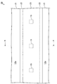
図2および図7に示すように、第3実施形態の照明装置30は、外装パネル11(貫通孔11a)、金属薄膜12a,12b、アウタレンズ13、ハウジング14、光源15、接合部分J、テーパー状部分Tなどを備え、車両外装用照明装置として用いられる。
<Third Embodiment>
As shown in FIGS. 2 and 7, the
第3実施形態の照明装置30において、第1実施形態の照明装置10と異なるのは、アウタレンズ13のフランジ部13bが省かれ、アウタレンズ13の側面全体がテーパー状部分Tになっている点である。
そして、ハウジング14の外周側壁の先端部分は、アウタレンズ13の裏面の外周縁部に溶着または接着により接合固定されている。
従って、第3実施形態によれば、第1実施形態の前記作用・効果のうち前記[1−4]を除く作用・効果を得ることができる。
尚、第3実施形態におけるアウタレンズ13のテーパー状部分Tは、第1実施形態におけるアウタレンズ13のフランジ部13bと同様に機能するため、第3実施形態においても、前記[1−4]と同等の作用・効果を得ることができる。
The
And the front-end | tip part of the outer peripheral side wall of the
Therefore, according to 3rd Embodiment, the effect | action and effect except said [1-4] can be acquired among the said effect | action and effect of 1st Embodiment.
Since the tapered portion T of the
また、第3実施形態では、アウタレンズ13とハウジング14の接合部分Jが、アウタレンズ13のテーパー状部分Tの裏面側に配置されているため、接合部分Jが外装パネル11によって完全に隠蔽されることから、第1実施形態の前記[1−3]の作用・効果をより確実に得ることができる。
Moreover, in 3rd Embodiment, since the junction part J of the
<別の実施形態>
本発明は前記各実施形態に限定されるものではなく、以下のように具体化してもよく、その場合でも、前記各実施形態と同等もしくはそれ以上の作用・効果を得ることができる。
<Another embodiment>
The present invention is not limited to the above-described embodiments, and may be embodied as follows. Even in this case, operations and effects equivalent to or higher than those of the above-described embodiments can be obtained.
[A]金属薄膜12a,12bを省き、光源15の放射光を透過しない不透明な樹脂材料によって外装パネル11を形成してもよい。
[B]金属薄膜12a,12bを、光源15の放射光を透過しない不透明な塗膜に置き換えてもよい。
[C]第1実施形態において、アウタレンズ13のテーパー状部分Tは、線形テーパー状に限らず、アウタレンズ13の表面から裾野状に広がるように傾斜していれば、どのようなテーパー状に形成してもよい。
[A] The metal
[B] The metal
[C] In the first embodiment, the tapered portion T of the
<用語の説明>
[特許請求の範囲]および[課題を解決するための手段]に記載した構成要素と、[発明を実施するための形態]に記載した構成部材との対応関係は以下のようになっている。
<Explanation of terms>
Correspondence between the constituent elements described in [Claims] and [Means for Solving the Problems] and the constituent members described in [Mode for Carrying Out the Invention] is as follows.
「第1部材」は、第1実施形態および第3実施形態では外装パネル11およびアウタレンズ13に該当し、第2実施形態では外装パネル21およびハウジング22に該当する。
「第2部材」は、第1実施形態および第3実施形態ではハウジング14に該当し、第2実施形態ではアウタレンズ23に該当する。
「第1材料部」は、第1実施形態および第3実施形態ではアウタレンズ13に該当し、第2実施形態ではハウジング22に該当する。
「第2材料部」は、第1実施形態および第3実施形態では外装パネル11に該当し、第2実施形態では外装パネル21に該当する。
The “first member” corresponds to the
The “second member” corresponds to the
The “first material portion” corresponds to the
The “second material portion” corresponds to the
本発明は、前記各局面および前記各実施形態の説明に何ら限定されるものではない。特許請求の範囲の記載を逸脱せず、当業者が容易に想到できる範囲で種々の変形態様も本発明に含まれる。本明細書の中で明示した公報などの内容は、その全ての内容を援用によって引用することとする。 The present invention is not limited to the description of each aspect and each embodiment. Various modifications are also included in the present invention as long as those skilled in the art can easily conceive without departing from the scope of the claims. The contents of publications and the like specified in the present specification are all incorporated by reference.
10,20,30…照明装置
11,21…外装パネル
12a,12b…金属薄膜
13,23…アウタレンズ
13a…凸部
13b…フランジ部
14,22…ハウジング
15…光源
J…接合部分
T…テーパー状部分
DESCRIPTION OF
Claims (10)
前記光源を収容するための第1部材および第2部材と
を備えた照明装置であって、
前記第1部材は、樹脂材料から成る第1材料部および第2材料部の2色成形によって一体形成され、
前記第1材料部は前記第2部材に接合され、
前記第2材料部は前記光源の放射光を透過しない照明装置。 A light source;
A lighting device comprising a first member and a second member for housing the light source,
The first member is integrally formed by two-color molding of a first material portion and a second material portion made of a resin material,
The first material part is bonded to the second member;
The second material unit is an illumination device that does not transmit the emitted light of the light source.
前記第2材料部は外装パネルであり、
前記第2部材は、前記光源が取付固定されたハウジングであり、
前記アウタレンズにおける前記外装パネルの裏面から露出された部分に前記ハウジングが接合されている、
請求項1に記載の照明装置。 The first material part is an outer lens that transmits the emitted light of the light source,
The second material part is an exterior panel;
The second member is a housing to which the light source is attached and fixed.
The housing is joined to a portion exposed from the back surface of the exterior panel in the outer lens.
The lighting device according to claim 1.
請求項2に記載の照明装置。 The joint portion between the outer lens and the housing is disposed on the back side of the exterior panel.
The lighting device according to claim 2.
請求項3に記載の照明装置。 A portion of the outer lens extends to the back surface of the exterior panel, and the housing is joined to the extended portion of the outer lens.
The lighting device according to claim 3.
請求項2〜4のいずれか一項に記載の照明装置。 The surface of the outer lens protrudes from the surface of the exterior panel,
The illuminating device as described in any one of Claims 2-4.
請求項2〜5のいずれか一項に記載の照明装置。 A side surface of the outer lens is formed in a tapered shape that is inclined so as to spread from the surface of the outer lens in a skirt shape.
The illumination device according to any one of claims 2 to 5.
請求項6に記載の照明装置。 The joint portion between the outer lens and the housing is disposed on the back side of the tapered portion of the outer lens.
The lighting device according to claim 6.
前記第2材料部は外装パネルであり、
前記第2部材は、前記光源の放射光を透過するアウタレンズであり、
前記ハウジングにおける前記外装パネルの開口部から露出された部分に前記アウタレンズが接合されている、
請求項1に記載の照明装置。 The first material part is a housing to which the light source is attached and fixed,
The second material part is an exterior panel;
The second member is an outer lens that transmits the emitted light of the light source,
The outer lens is joined to a portion exposed from the opening of the exterior panel in the housing,
The lighting device according to claim 1.
請求項1〜8のいずれか一項に記載の照明装置。 A metal thin film formed on at least the surface of the second material portion;
The illuminating device as described in any one of Claims 1-8.
請求項9に記載の照明装置。 The first material portion is made of a resin material that is difficult to form the metal thin film.
The lighting device according to claim 9.
Priority Applications (1)
| Application Number | Priority Date | Filing Date | Title |
|---|---|---|---|
| JP2016057717A JP6645295B2 (en) | 2016-03-22 | 2016-03-22 | Lighting equipment |
Applications Claiming Priority (1)
| Application Number | Priority Date | Filing Date | Title |
|---|---|---|---|
| JP2016057717A JP6645295B2 (en) | 2016-03-22 | 2016-03-22 | Lighting equipment |
Publications (2)
| Publication Number | Publication Date |
|---|---|
| JP2017174573A true JP2017174573A (en) | 2017-09-28 |
| JP6645295B2 JP6645295B2 (en) | 2020-02-14 |
Family
ID=59971352
Family Applications (1)
| Application Number | Title | Priority Date | Filing Date |
|---|---|---|---|
| JP2016057717A Active JP6645295B2 (en) | 2016-03-22 | 2016-03-22 | Lighting equipment |
Country Status (1)
| Country | Link |
|---|---|
| JP (1) | JP6645295B2 (en) |
Citations (14)
| Publication number | Priority date | Publication date | Assignee | Title |
|---|---|---|---|---|
| JPH04660U (en) * | 1990-04-19 | 1992-01-07 | ||
| JPH0652707A (en) * | 1992-07-29 | 1994-02-25 | Yazaki Corp | Display device |
| JP2000016166A (en) * | 1998-07-06 | 2000-01-18 | Ichikoh Ind Ltd | Lighting fixture for vehicle |
| JP2000159010A (en) * | 1998-11-24 | 2000-06-13 | Asahi Sakai Kk | Character-lighting number plate device |
| JP2001155511A (en) * | 1999-11-26 | 2001-06-08 | Mitsubishi Motors Corp | Lighting structure for on-vehicle lamp |
| JP2005047411A (en) * | 2003-07-30 | 2005-02-24 | Sakae Riken Kogyo Co Ltd | Door mirror device with turn signal lamp |
| JP2005067391A (en) * | 2003-08-25 | 2005-03-17 | Sakae Riken Kogyo Co Ltd | Door mirror device with turn signal lamp |
| JP2010208513A (en) * | 2009-03-11 | 2010-09-24 | Toyoda Gosei Co Ltd | Front grill |
| JP2010287391A (en) * | 2009-06-10 | 2010-12-24 | Koito Mfg Co Ltd | Lighting fixture for vehicle equipped with tapered-off inner lens |
| JP2014113841A (en) * | 2012-12-06 | 2014-06-26 | Sakae Riken Kogyo Co Ltd | Vehicle lighting fixture |
| JP2014113843A (en) * | 2012-12-06 | 2014-06-26 | Sakae Riken Kogyo Co Ltd | Vehicle lamp fitting |
| JP2014113842A (en) * | 2012-12-06 | 2014-06-26 | Sakae Riken Kogyo Co Ltd | Vehicle lamp fitting |
| JP2014172440A (en) * | 2013-03-06 | 2014-09-22 | Mitsuba Corp | Light body for vehicle and door mirror with light body |
| JP2015202636A (en) * | 2014-04-15 | 2015-11-16 | スタンレー電気株式会社 | Two-color molding |
-
2016
- 2016-03-22 JP JP2016057717A patent/JP6645295B2/en active Active
Patent Citations (14)
| Publication number | Priority date | Publication date | Assignee | Title |
|---|---|---|---|---|
| JPH04660U (en) * | 1990-04-19 | 1992-01-07 | ||
| JPH0652707A (en) * | 1992-07-29 | 1994-02-25 | Yazaki Corp | Display device |
| JP2000016166A (en) * | 1998-07-06 | 2000-01-18 | Ichikoh Ind Ltd | Lighting fixture for vehicle |
| JP2000159010A (en) * | 1998-11-24 | 2000-06-13 | Asahi Sakai Kk | Character-lighting number plate device |
| JP2001155511A (en) * | 1999-11-26 | 2001-06-08 | Mitsubishi Motors Corp | Lighting structure for on-vehicle lamp |
| JP2005047411A (en) * | 2003-07-30 | 2005-02-24 | Sakae Riken Kogyo Co Ltd | Door mirror device with turn signal lamp |
| JP2005067391A (en) * | 2003-08-25 | 2005-03-17 | Sakae Riken Kogyo Co Ltd | Door mirror device with turn signal lamp |
| JP2010208513A (en) * | 2009-03-11 | 2010-09-24 | Toyoda Gosei Co Ltd | Front grill |
| JP2010287391A (en) * | 2009-06-10 | 2010-12-24 | Koito Mfg Co Ltd | Lighting fixture for vehicle equipped with tapered-off inner lens |
| JP2014113841A (en) * | 2012-12-06 | 2014-06-26 | Sakae Riken Kogyo Co Ltd | Vehicle lighting fixture |
| JP2014113843A (en) * | 2012-12-06 | 2014-06-26 | Sakae Riken Kogyo Co Ltd | Vehicle lamp fitting |
| JP2014113842A (en) * | 2012-12-06 | 2014-06-26 | Sakae Riken Kogyo Co Ltd | Vehicle lamp fitting |
| JP2014172440A (en) * | 2013-03-06 | 2014-09-22 | Mitsuba Corp | Light body for vehicle and door mirror with light body |
| JP2015202636A (en) * | 2014-04-15 | 2015-11-16 | スタンレー電気株式会社 | Two-color molding |
Also Published As
| Publication number | Publication date |
|---|---|
| JP6645295B2 (en) | 2020-02-14 |
Similar Documents
| Publication | Publication Date | Title |
|---|---|---|
| JP6607146B2 (en) | Luminous emblem | |
| JP6199144B2 (en) | Lighting device | |
| EP2628638B1 (en) | Automotive body element comprising a light source on its inner face | |
| EP2990720B1 (en) | Vehicle lighting unit | |
| US10145537B2 (en) | Illumination unit and vehicle lamp | |
| US10870404B2 (en) | Elongate illuminated automotive design element, injection molded vehicle parts, and methods of manufacturing same | |
| JP6879052B2 (en) | Vehicle lighting | |
| US20170355302A1 (en) | Display apparatus and manufacturing method thereof | |
| JP2017027804A (en) | Decorative lighting device | |
| JP5921265B2 (en) | Vehicle lighting | |
| JP5789628B2 (en) | Lamp | |
| JP5994759B2 (en) | Lighting device | |
| JP6579327B2 (en) | Lighting device | |
| JP2017021231A (en) | Light emission emblem | |
| US10723045B2 (en) | Vehicular lamp and vehicle comprising same | |
| JP6645295B2 (en) | Lighting equipment | |
| JP2007091085A (en) | Light emitting display device | |
| JP6311884B2 (en) | Lighting device | |
| JP6274438B2 (en) | Lighting device | |
| JP6057080B2 (en) | Light guide and lighting device | |
| JP5633441B2 (en) | Vehicle lighting device | |
| JP2017054630A (en) | Clearance lamp structure of vehicle | |
| JP6579328B2 (en) | Lighting device | |
| JP2005301157A (en) | Planar illuminant | |
| TW200936439A (en) | License plate light shading structure of tail lamp |
Legal Events
| Date | Code | Title | Description |
|---|---|---|---|
| A621 | Written request for application examination |
Free format text: JAPANESE INTERMEDIATE CODE: A621 Effective date: 20180423 |
|
| A977 | Report on retrieval |
Free format text: JAPANESE INTERMEDIATE CODE: A971007 Effective date: 20190215 |
|
| A131 | Notification of reasons for refusal |
Free format text: JAPANESE INTERMEDIATE CODE: A131 Effective date: 20190226 |
|
| A521 | Request for written amendment filed |
Free format text: JAPANESE INTERMEDIATE CODE: A523 Effective date: 20190416 |
|
| A131 | Notification of reasons for refusal |
Free format text: JAPANESE INTERMEDIATE CODE: A131 Effective date: 20190731 |
|
| A521 | Request for written amendment filed |
Free format text: JAPANESE INTERMEDIATE CODE: A523 Effective date: 20190925 |
|
| TRDD | Decision of grant or rejection written | ||
| A01 | Written decision to grant a patent or to grant a registration (utility model) |
Free format text: JAPANESE INTERMEDIATE CODE: A01 Effective date: 20191210 |
|
| A61 | First payment of annual fees (during grant procedure) |
Free format text: JAPANESE INTERMEDIATE CODE: A61 Effective date: 20191223 |
|
| R150 | Certificate of patent or registration of utility model |
Ref document number: 6645295 Country of ref document: JP Free format text: JAPANESE INTERMEDIATE CODE: R150 |